Val3 Reference Manual
User Manual:
Open the PDF directly: View PDF ![]() .
.
Page Count: 160 [warning: Documents this large are best viewed by clicking the View PDF Link!]
- VAL3 REFERENCE MANUAL
- TABLE OF CONTENTS
- Introduction
- VAL3 language elements
- Simple types
- User interface
- Tasks
- Libraries
- Robot control
- Arm positions
- Movement control
- 9.1. TRAJECTORY CONTROL
- 9.2. Movement anticipation
- 9.3. SPEED MONITORING
- 9.4. Real-time movement control
- 9.5. mdesc type
- 9.6. Movement instructions
- Options
- Appendix

© Stäubli Faverges 2006
VAL3 REFERENCE MANUAL
Version 5.3
D28062804A - 02/2006


D28062804A - 02/2006 3 / 160
TABLE OF CONTENTS
1 - INTRODUCTION................................................................................ 11
2 - VAL3 LANGUAGE ELEMENTS ........................................................ 15
2.1 APPLICATIONS..................................................................................................................... 17
2.1.1 Definition .................................................................................................................... 17
2.1.2 Default content ........................................................................................................... 17
2.1.3 Start/stop .................................................................................................................... 17
2.1.4 Application parameters............................................................................................... 17
2.1.4.1 Unit of length ............................................................................................... 18
2.1.4.2 Size of the execution memory..................................................................... 18
2.2 PROGRAMS .......................................................................................................................... 18
2.2.1 Definition .................................................................................................................... 18
2.2.2 Re-entry...................................................................................................................... 18
2.2.3 start() program............................................................................................................ 18
2.2.4 stop() program............................................................................................................ 18
2.3 DATA TYPES......................................................................................................................... 19
2.3.1 Definition .................................................................................................................... 19
2.3.2 Simple types............................................................................................................... 19
2.3.3 Structured types ......................................................................................................... 19
2.4 CONSTANTS ......................................................................................................................... 19
2.4.1 Definition .................................................................................................................... 19
2.4.2 Simple type constants ................................................................................................ 19
2.4.3 Structured type constants........................................................................................... 20
2.4.4 Constants table .......................................................................................................... 20
2.5 VARIABLES........................................................................................................................... 20
2.5.1 Definition .................................................................................................................... 20
2.5.2 Variable scope............................................................................................................ 20
2.5.3 Accessing a variable value......................................................................................... 20
2.5.4 Parameter passed "by value" ..................................................................................... 21
2.5.5 Parameter passed "by reference" .............................................................................. 21
2.6 SEQUENCE CONTROL INSTRUCTIONS............................................................................. 22
Comment // ...................................................................................................................................... 22
call program .................................................................................................................................... 22
return program ................................................................................................................................ 23
if control instruction ....................................................................................................................... 23
while control instruction ................................................................................................................... 24
do ... until control instruction ...........................................................................................................24
for control instruction ....................................................................................................................... 25
switch control instruction ................................................................................................................ 26

4 / 160 D28062804A - 02/2006
3 - SIMPLE TYPES................................................................................. 27
3.1 INSTRUCTIONS..................................................................................................................... 29
num size(variable) ........................................................................................................................... 29
3.2 BOOL TYPE ........................................................................................................................... 30
3.2.1 Definition .................................................................................................................... 30
3.2.2 Operators ................................................................................................................... 30
3.3 NUM TYPE ............................................................................................................................. 31
3.3.1 Definition .................................................................................................................... 31
3.3.2 Operators ................................................................................................................... 32
3.3.3 Instructions ................................................................................................................. 32
num sin(num angle) ........................................................................................................................ 32
num asin(num Value) ...................................................................................................................... 33
num cos(num angle) ....................................................................................................................... 33
num acos(num Value) ..................................................................................................................... 33
num tan(num angle) ........................................................................................................................ 34
num atan(num Value) ..................................................................................................................... 34
num abs(num Value) ....................................................................................................................... 34
num sqrt(num Value) ...................................................................................................................... 35
num exp(num Value) ....................................................................................................................... 35
num ln(num Value) .......................................................................................................................... 36
num log(num Value) ....................................................................................................................... 36
num roundUp(num Value) .............................................................................................................. 37
num roundDown(num Value) ......................................................................................................... 37
num round(num Value) ................................................................................................................... 37
num min(num x, num y) .................................................................................................................. 38
num max(num x, num y) .................................................................................................................38
num limit(num Value, num min, num max) ..................................................................................... 38
num sel(bool condition, num Value1, num Value2) ........................................................................ 39
3.4 STRING TYPE........................................................................................................................ 40
3.4.1 Definition .................................................................................................................... 40
3.4.2 Operators ................................................................................................................... 40
3.4.3 Instructions ................................................................................................................. 40
string toString(string format, num Value) ....................................................................................... 40
string toNum(string string, num& Value, bool& report) ................................................................... 41
string chr(num Ascii Code) ............................................................................................................. 42
num asc(string text, num position) .................................................................................................. 43
string left(string string, num size) .................................................................................................... 43
string right(string string, num size) ................................................................................................. 44
string mid(string string, num size, num position) ............................................................................ 44
string insert(string string, string insertion, num position) ................................................................ 45
string delete(string string, num size, num position) ........................................................................ 45
num replace(string string, string replacement, num size, num position) ........................................ 46
num find(string string1, string string2) ............................................................................................ 46
num len(string string) ...................................................................................................................... 47
3.5 DIO TYPE ............................................................................................................................... 48
3.5.1 Definition .................................................................................................................... 48
3.5.2 Operators ................................................................................................................... 48
3.5.3 Instructions ................................................................................................................. 49
void dioLink(dio& variable, dio source) .......................................................................................... 49
num dioGet(dio dTable) .................................................................................................................. 49
num dioSet(dio dTable, num Value) ............................................................................................... 50

D28062804A - 02/2006 5 / 160
3.6 AIO TYPE............................................................................................................................... 51
3.6.1 Definition .................................................................................................................... 51
3.6.2 Instructions ................................................................................................................. 51
void aioLink(aio& variable, aio source) ........................................................................................... 51
num aioGet(aio input) ...................................................................................................................... 51
num aioSet(aio output, num Value) ................................................................................................. 52
3.7 SIO TYPE ............................................................................................................................... 53
3.7.1 Definition .................................................................................................................... 53
3.7.2 Instructions ................................................................................................................. 54
void sioLink(sio& variable, sio source) ........................................................................................... 54
num clearBuffer(sio input) .............................................................................................................. 54
num sioGet(sio input, num& data) .................................................................................................. 54
num sioSet(sio output, num& data) ................................................................................................. 55
4 - USER INTERFACE............................................................................ 57
4.1 USER PAGE .......................................................................................................................... 59
4.2 INSTRUCTIONS..................................................................................................................... 59
void userPage(), void userPage(bool fixed) ................................................................................... 59
void gotoxy(num x, num y) ............................................................................................................. 60
void cls() .......................................................................................................................................... 60
void put() void putln() ..................................................................................................................... 60
void title(string string) ...................................................................................................................... 61
num get() ......................................................................................................................................... 61
num getKey() .................................................................................................................................. 63
bool isKeyPressed(num code) ....................................................................................................... 63
void popUpMsg(string string) .......................................................................................................... 63
void logMsg(string string) ................................................................................................................64
string getProfile() ............................................................................................................................ 64
5 - TASKS ............................................................................................... 65
5.1 DEFINITION ........................................................................................................................... 67
5.2 RESUMING AFTER AN EXECUTION ERROR ..................................................................... 67
5.3 VISIBILITY ............................................................................................................................. 67
5.4 SEQUENCING ....................................................................................................................... 68
5.5 SYNCHRONOUS TASKS ...................................................................................................... 69
5.6 OVERRUN.............................................................................................................................. 69
5.7 INPUTS / OUTPUTS REFRESH ............................................................................................ 69
5.8 SYNCHRONIZATION............................................................................................................. 70
5.9 SHARING RESOURCES ....................................................................................................... 71

6 / 160 D28062804A - 02/2006
5.10 INSTRUCTIONS..................................................................................................................... 72
void taskSuspend(string name) ..................................................................................................... 72
void taskResume(string name, num skip) ...................................................................................... 72
void taskKill(string name) ............................................................................................................... 73
void setMutex(bool& mutex) ........................................................................................................... 73
num taskStatus(string name) ......................................................................................................... 74
void taskCreate string name, num priority, program(...) ................................................................. 75
void taskCreateSync string name, num period, bool& overrun, program(...) ................................. 76
void wait(bool condition) ................................................................................................................. 77
void delay(num seconds) ................................................................................................................ 77
num clock() ..................................................................................................................................... 78
bool watch(bool condition, num seconds) ...................................................................................... 78
6 - LIBRARIES........................................................................................ 79
6.1 DEFINITION ........................................................................................................................... 81
6.2 INTERFACE ........................................................................................................................... 81
6.3 INTERFACE IDENTIFIER ...................................................................................................... 81
6.4 CONTENT .............................................................................................................................. 81
6.5 LOADING AND UNLOADING................................................................................................ 82
6.6 INSTRUCTIONS..................................................................................................................... 83
num identifier:libLoad(string path) .................................................................................................. 83
num identifier:libSave(), num libSave() .......................................................................................... 83
num libDelete(string path) .............................................................................................................. 83
string identifier:libPath(), string libPath() ...................................................................................... 84
bool libList(string path, string& contents) .................................................................................... 84
7 - ROBOT CONTROL ........................................................................... 85
7.1 INSTRUCTIONS..................................................................................................................... 87
void disablePower() ....................................................................................................................... 87
void enablePower() ........................................................................................................................ 87
bool isPowered() ............................................................................................................................ 87
bool isCalibrated() .......................................................................................................................... 88
num workingMode(), num workingMode(num& status) ............................................................... 88
num speedScale() .......................................................................................................................... 89
num esStatus() ............................................................................................................................... 89
8 - ARM POSITIONS .............................................................................. 91
8.1 INTRODUCTION .................................................................................................................... 92
8.2 JOINT TYPE........................................................................................................................... 92
8.2.1 Definition .................................................................................................................... 92
8.2.2 Operators ................................................................................................................... 93
8.2.3 Instructions ................................................................................................................. 93
joint abs(joint jPosition) ................................................................................................................... 93
joint herej() ...................................................................................................................................... 94
bool isInRange(joint jPosition) ........................................................................................................ 94
void setLatch(dio input) (CS8C only) ............................................................................................. 95
bool getLatch(joint& jPosition) (CS8C only) ................................................................................... 96

D28062804A - 02/2006 7 / 160
8.3 TRSF TYPE............................................................................................................................ 97
8.3.1 Definition .................................................................................................................... 97
8.3.2 Orientation.................................................................................................................. 98
8.3.3 Operators ................................................................................................................. 100
8.3.4 Instructions ............................................................................................................... 100
num distance(trsf position1, trsf position2) ................................................................................... 100
8.4 FRAME TYPE ...................................................................................................................... 101
8.4.1 Definition .................................................................................................................. 101
8.4.2 Use ........................................................................................................................... 101
8.4.3 Operators ................................................................................................................. 102
8.4.4 Instructions ............................................................................................................... 102
num setFrame(point origin, point axisOx, point planeOxy, frame& reference) ............................. 102
8.5 TOOL TYPE ......................................................................................................................... 102
8.5.1 Definition .................................................................................................................. 102
8.5.2 Use ........................................................................................................................... 103
8.5.3 Operators ................................................................................................................. 103
8.5.4 Instructions ............................................................................................................... 104
void open(tool tool) ........................................................................................................................ 104
void close(tool tool) ....................................................................................................................... 104
8.6 POINT TYPE ........................................................................................................................ 105
8.6.1 Definition .................................................................................................................. 105
8.6.2 Operators ................................................................................................................. 105
8.6.3 Instructions ............................................................................................................... 106
num distance(point position1, point position2) ............................................................................. 106
point compose(point position, frame reference, trsf transformation) ............................................ 107
point appro(point position, trsf transformation) ............................................................................. 108
point here(tool tTool, frame fFrame) .............................................................................................. 108
point jointToPoint(tool tool, frame reference, joint position) ......................................................... 109
bool pointToJoint(tool tool, joint initial, point position,joint& coordinates) .................................... 109
trsf position(point position, frame reference) ................................................................................ 110
8.7 CONFIG TYPE ..................................................................................................................... 111
8.7.1 Introduction............................................................................................................... 112
8.7.2 Definition .................................................................................................................. 112
8.7.3 Operators ................................................................................................................. 113
8.7.4 Configuration (RX/TX arm)....................................................................................... 113
8.7.4.1 Shoulder configuration .............................................................................. 113
8.7.4.2 Elbow configuration................................................................................... 114
8.7.4.3 Wrist configuration .................................................................................... 114
8.7.5 Configuration (RS arm) ............................................................................................ 115
8.7.6 Instructions ............................................................................................................... 115
config config(joint position) ........................................................................................................... 115

8 / 160 D28062804A - 02/2006
9 - MOVEMENT CONTROL.................................................................. 117
9.1 TRAJECTORY CONTROL................................................................................................... 119
9.1.1 Types of movement: point-to-point, straight line, circle ............................................ 119
9.1.2 Movement sequencing ............................................................................................. 121
9.1.2.1 Blending .................................................................................................... 121
9.1.2.2 Cancel blending ........................................................................................ 122
9.1.3 Movement resumption .............................................................................................. 123
9.1.4 Particularities of Cartesian movements (straight line, circle).................................... 124
9.1.4.1 Interpolation of the orientation................................................................... 124
9.1.4.2 Configuration change (Arm RX/TX) .......................................................... 126
9.1.4.3 Singularities (Arm RX/TX) ......................................................................... 128
9.2 MOVEMENT ANTICIPATION .............................................................................................. 128
9.2.1 Principle.................................................................................................................... 128
9.2.2 Anticipation and blending ......................................................................................... 129
9.2.3 Synchronization ........................................................................................................ 129
9.3 SPEED MONITORING ......................................................................................................... 130
9.3.1 Principle.................................................................................................................... 130
9.3.2 Simple settings ......................................................................................................... 130
9.3.3 Advanced settings .................................................................................................... 130
9.3.4 Enveloppe error ........................................................................................................ 131
9.4 REAL-TIME MOVEMENT CONTROL.................................................................................. 131
9.5 MDESC TYPE ...................................................................................................................... 132
9.5.1 Definition .................................................................................................................. 132
9.5.2 Operators ................................................................................................................. 132
9.6 MOVEMENT INSTRUCTIONS ............................................................................................. 133
void movej(joint joint, tool tool, mdesc desc) ................................................................................ 133
void movel(point point, tool tool, mdesc desc) .............................................................................. 134
void movec(Point intermediate, Point target, tool tool, mdesc desc) ............................................ 135
void stopMove() ............................................................................................................................ 136
void resetMotion(), void resetMotion(joint startingPoint) ............................................................ 136
void restartMove() ........................................................................................................................ 137
void waitEndMove() ..................................................................................................................... 137
bool isEmpty() .............................................................................................................................. 138
bool isSettled() .............................................................................................................................138
void autoConnectMove(bool active), bool autoConnectMove() ................................................ 138

D28062804A - 02/2006 9 / 160
10 - OPTIONS......................................................................................... 139
10.1 COMPLIANT MOVEMENTS WITH FORCE CONTROL...................................................... 141
10.1.1 Principle.................................................................................................................... 141
10.1.2 Programming............................................................................................................ 141
10.1.3 Force control ............................................................................................................ 141
10.1.4 Limitations ................................................................................................................ 142
10.1.5 Instructions ............................................................................................................... 142
void movejf(joint position, tool tool, mdesc desc, num force) ....................................................... 142
void movelf(point point, tool tool, mdesc desc, num force) ........................................................... 143
bool isCompliant() ........................................................................................................................ 144
10.2 ALTER: REAL TIME CONTROL ON A PATH .................................................................... 145
10.2.1 Principle.................................................................................................................... 145
10.2.2 Programming............................................................................................................ 145
10.2.3 Constraints ............................................................................................................... 145
10.2.4 Safety ....................................................................................................................... 146
10.2.5 Limitations ................................................................................................................ 146
10.2.6 Instructions ............................................................................................................... 146
void alterMovej(joint target, tool tcp, mdesc speed) ..................................................................... 146
void alterMovel(point target, tool tcp, mdesc speed) .................................................................... 147
void alterMovec (point intermediate, point target, tool tcp, mdesc speed) ................................... 147
num alterBegin(frame alterReference, mdesc velocity)
num alterBegin(tool alterReference, mdesc velocity) ................................................................... 148
num alterEnd() ..............................................................................................................................149
num alter(trsf alteration) ................................................................................................................ 149
num alterStopTime() .................................................................................................................... 150
11 - APPENDIX....................................................................................... 151
11.1 EXECUTION ERROR CODES............................................................................................. 153
11.2 CONTROL PANEL KEYBOARD KEY CODES................................................................... 154
12 - ILLUSTRATION............................................................................... 155
13 - INDEX .............................................................................................. 157


Chapter 1 - Introduction
D28062804A - 02/2006 13 / 160
VAL3 is a high-level programming language designed to control Stäubli robots in industrial handling and
assembly applications.
VAL3 language combines the basic features of a standard real-time high-level computer language with
functionalities that are specific to industrial cell robot control:
•robot control tools
•geometrical modelling tools
•input/output control tools
This reference manual explains the essential concepts of robot programming and describes the VAL3
instructions which fall into the following categories:
•Language elements
•Simple types
•User interface
•Tasks
•Libraries
•Robot control
•Arm position
•Movement control
Each instruction,together with its syntax, is listed in the table of contents for quick reference purposes.


Chapter 2 - VAL3 language elements
D28062804A - 02/2006 17 / 160
VAL3 consists of the following elements:
•applications
•programs
•libraries
•data types
•constants
•variables (global and local datas, parameters)
•tasks
2.1. APPLICATIONS
2.1.1. DEFINITION
A VAL3 application is a self-contained software package designed for programming robots and inputs/
outputs associated with a CS8 controller.
A VAL3 application comprises the following elements:
-a set of programs: the VAL3 instructions to be executed
-a set of global datas: the application data
-a set of libraries: the outside instructions and data used by the application
When an application is running, it also contains:
-a set of tasks: the programs being executed
2.1.2. DEFAULT CONTENT
A VAL3 application always contains the start() and stop() programs, a world frame (frame type) and a
flange tool (tool type).
When a VAL3 application is created, it also contains the instructions and data types that are specific to the
arm model.
Further details of these elements can be found in the chapters describing each element type.
2.1.3. START/STOP
VAL3 instructions are not used to control applications: applications can only be loaded, unloaded, started
and stopped via the CS8 user interface of the controller.
When a VAL3 application is started up, its start() program is run.
A VAL3 application stops automatically when its last task is completed: the stop() program is then
executed. All the tasks created by libraries, if any remain, are deleted in the reverse order to that in which
they were created.
If a VAL3 application is stopped via the CS8 user interface, the start task, if it still exists, is immediately
destroyed. The stop() program is run next, and then any remaining application tasks are deleted in the
reverse order to that in which they were created.
2.1.4. APPLICATION PARAMETERS
The following parameters can be used to configure a VAL3 application:
-unit of length
-size of the execution memory
These parameters cannot be accessed via a VAL3 instruction and can only be changed via the CS8 user
interface.

18 / 160 D28062804A - 02/2006
2.1.4.1. UNIT OF LENGTH
In VAL3 applications, the unit of length is either the millimetre or the inch. It is used by the VAL3
geometrical data types: frame, point, transformation, tool, and trajectory blending.
The unit of length of an application is defined when an application is created, and it cannot be changed
subsequently.
2.1.4.2. SIZE OF THE EXECUTION MEMORY
The size of the execution memory of a VAL3 application is the amount of memory available for each of its
tasks, to store data such as the local program variables. By default, it is 5000 bytes.
This level may not be sufficient for applications containing large tables with local variables or recursive
algorithms: in this case, it must be increased via the CS8 user interface.
2.2. PROGRAMS
2.2.1. DEFINITION
A program is a sequence of VAL3 instructions to be executed.
A program consists of the following elements:
-sequence of instructions: the VAL3 instructions to be executed
-A set of local variables: the internal program data
-A set of parameters: the data supplied to the program when it is called
Programs are used to group sequences of instructions that can be executed at various points in an
application. In addition to saving program time, they also highlight the structure of the applications,
facilitate programming and maintenance and improve readability.
The number of instructions in a program is limited only by the amount of memory available in the system.
The number of local variables and parameters is limited only by the size of the execution memory for the
application.
2.2.2. RE-ENTRY
The programs are re-entrant; this means that a program can call itself recursively (call instruction), or it
can be called concurrently by several tasks. Each program call has its own specific variables and
parameters.
2.2.3. START() PROGRAM
The start() program is the program called when the VAL3 application is started up. It cannot have any
parameters.
Typically, this program includes all the operations required to run the application: initialization of the global
datas and the inputs/outputs, starting up the application tasks, etc.
The application does not necessarily terminate at the end of the start() program, if other application tasks
are still running.
The start() program can be called from within a program (call instruction) in the same way as any other
program.
2.2.4. STOP() PROGRAM
The stop() program is the program called when the VAL3 application stops. It cannot have any
parameters.
Typically, this program includes all the operations required to stop the application correctly: resetting the
inputs/outputs and stopping the application tasks according to an appropriate sequence, etc.
The stop() program can be called from within a program (call instruction) in the same way as any other
program: calling the stop() program does not stop the application.

Chapter 2 - VAL3 language elements
D28062804A - 02/2006 19 / 160
2.3. DATA TYPES
2.3.1. DEFINITION
A VAL3 variable or constant type is a characteristic that allows the system to control the applications and
programs that can use it.
All the VAL3 constants and variables have a type. This enables the system to run an initial check when
editing a program and hence detect certain programming errors immediately.
2.3.2. SIMPLE TYPES
The VAL3 language supports the following simple types:
-bool type: for Boolean values (true/false)
-num type: for numeric values
-string type: for character strings
-dio type: for on/off inputs/outputs
-aio type: for numeric inputs/outputs (analogue or digital)
-sio type: for serial ports inputs/outputs and ethernet sockets
2.3.3. STRUCTURED TYPES
Structured types combine typed data, the fields of the structured type. Fields of the structured type can be
accessed individually by their name.
The VAL3 language supports the following structured types:
-trsf type: for Cartesian geometrical transformations
-frame type: for Cartesian geometrical frames
-tool type: for robot mounted tools
-point type: for the Cartesian positions of a tool
-joint type: for robot revolute positions
-config type: for robot configurations
-mdesc type: for robot movement parameters
2.4. CONSTANTS
2.4.1. DEFINITION
A constant is a data item that is defined directly in a VAL3 program without previously being declared. A
constant has a type that is determined implicitly by the system.
2.4.2. SIMPLE TYPE CONSTANTS
The precise syntax of a simple type constant is specified in the chapter describing each simple type.
Example
bool bBool
num nPi
string sString
bBool = true
nPi = 3.141592653
sString = "this is a string"

20 / 160 D28062804A - 02/2006
2.4.3. STRUCTURED TYPE CONSTANTS
The value of a structured type constant is defined by the sequence of values in its fields. The sequence
order is specified in the chapter describing each structured type.
Example
procedure dummy(trsf t, dio d)
point p
p = {{100, -50, 200, 0, 0, 0}, {sfree, efree, wfree}}
call dummy({a+b, 2* c, 120, limit(c, 0, 90), 0, 0}, io:valve1)
2.4.4. CONSTANTS TABLE
A constants table must be initialized entry by entry.
Example
joint j[5]
// For 6 axis arms
j[0] = {0, 0, 0, 0, 0, 0}
j[1] = {90, 0, 90, 0, 0, 0}
j[2] = {-90, 0, 90, 0, 0, 0}
j[3] = {90, 0, 0, -90, 0, 0}
j[4] = {-90, 0, 0, -90, 0, 0}
2.5. VARIABLES
2.5.1. DEFINITION
A variable is a data item referenced by its name in a program.
A variable is identified by:
-its name: a character string
-its type: one of the VAL3 types described previously
-its size: for a table, the number of elements it contains
-its scope: the program or programs that can use the variable
A variable name is a string of 1 to 15 characters selected from "a..zA..Z0..9_".
All variables can be used as arrays. Simple variables are size 1. The size() instruction enables the size of
a variable to be known.
2.5.2. VARIABLE SCOPE
The scope of a variable can be:
•global: all programs in the application can use the variable, or
•local: the variable can only be accessed in the program in which it is declared
When a global variable and a local variable have the same name, the program in which the local variable
is declared will use the local variable and will be unable to access the global variable.
Program parameters are local variables that can only be accessed in the program in which they are
declared.
2.5.3. ACCESSING A VARIABLE VALUE
The elements of an array can be accessed by using an index between square brackets ‘[‘ and ‘]’. The
index must be between 0 and (size-1), otherwise an execution error is generated.
If no index is specified, the index 0 is used: var[0] is equivalent to var.
The fields of structured type variables can be accessed using a ‘.’ followed by the field name.

Chapter 2 - VAL3 language elements
D28062804A - 02/2006 21 / 160
Example
2.5.4. PARAMETER PASSED "BY VALUE"
When a parameter is passed "by value", the system creates a local variable and initializes it with the value
of the variable or expression supplied by the calling program.
The variables of the calling program used as "by value" parameters do not change, even if the called
program changes the value of the parameter.
A data array cannot be passed by value.
Example:
2.5.5. PARAMETER PASSED "BY REFERENCE"
When a parameter is passed "by reference", the program no longer works on a copy of the data item
passed by the caller, but on the data item itself, which is simply renamed locally.
The values of the variables of the calling program used as "by reference" parameters change when the
called program changes the value of the parameter.
All the components of a table passed by reference can be used or modified. If an array component is
passed by reference, that component and all following components can be used and modified. In this
case, the parameter is seen as a table that starts with the component passed by the call. The size()
instruction can be used to determine the effective parameter size.
When a constant or an expression are passed "by reference", the corresponding assigned parameter has
no effect: the parameter retains the value of the constant or expression.
num a // a is a size 1 num type variable
num b[10] // b is a size 10 num type variable
trsf t
point p
a = 0 // Initialization of a simple type variable
a[0] = 0 // Correct: equivalent to a = 0
b[0] = 0 // Initialization of the first element in table b
b = 0 // Correct: equivalent to b[0] = 0
b[5] = 5 // Initialization of the sixth element in table b
b[5.13] = 7 // Correct: equivalent to b[5] = 7 (only the integer part is used)
b[-1] = 0 // error: index less than 0
b[10] = 0 // error: index too high
t = p.trsf // Initialization of t
p.trsf.x = 100 // Initialization of the x field of the trsf field of the p variable
procedure dummy(num x) // x is passed by value
begin
x=0
putln(x) // displays 0
end
num a
a=10
putln(a) // displays 10
call dummy(a) // displays 0
putln(a) // displays 10: a is not modified by dummy()

22 / 160 D28062804A - 02/2006
Example:
2.6. SEQUENCE CONTROL INSTRUCTIONS
Comment //
Syntax
// <string>
Function
A line starting with « // » is not evaluated and the evaluation resumes on the next line.
Example
// This is an example of a comment
call program
Syntax
call program([parameter1][,parameter2])
Function
Runs the specified program with the specified parameters.
procedure dummy(num& x) // x is passed by reference
begin
x=0
putln(x) // displays 0
end
procedure element(num& x)
begin
x[3] = 0
putln(size(x))
end
num a
num b[10]
a=10
putln(a) // displays 10
call dummy(a) // displays 0
putln(a) // displays 0: a is modified by dummy()
b[2] = 2
b[5] = 5
call element(b[2]) // displays 8, elements 0 and 1 in b are not passed
putln(b[5]) // displays 0: b[5] is modified by element()

Chapter 2 - VAL3 language elements
D28062804A - 02/2006 23 / 160
Example
// Calls the pick() and place() programs for i,j between 1 and 10
for i = 1 to 10
for j = 1 to 10
call pick (i, j)
call place (i, j)
endFor
endFor
return program
Syntax
return
Function
Exits the current program immediately. If this program was called by a call, execution resumes after the
call in the calling program. Otherwise (if the program is the start() program or the starting point of a task),
the current task is completed.
if control instruction
Syntax
if <bool condition>
<instructions>
[else
<instructions>]
endIf
Function
When the evaluation of the Boolean condition is (true), all the following instructions up to the else
keyword, if present, or the next endIf are evaluated.
When the expression is (false), the instructions evaluated are those between the else and endIf
keywords, if the else keyword is present. In all cases, the program then resumes after the endIf keyword.
Parameter
Example
string s
num a
// s = "a=0" if a=0, else "a = ? "
s = "a = ? "
if a==0
s = "a=0"
endIf
// s = "a=0" if a=0, else "a <> 0"
s = "a = ? "
if a==0
s = "a = 0"
else
s = "a <> 0"
endIf
bool condition Boolean expression to be evaluated

24 / 160 D28062804A - 02/2006
while control instruction
Syntax
while <bool condition>
<instructions>
endWhile
Function
The instructions between while and endWhile are executed when the Boolean condition expression is
(true).
If the Boolean condition expression is not true at the first evaluation, the instructions between while and
endWhile are not executed.
Parameter
Example
do ... until control instruction
Syntax
do
<instructions>
until <bool condition>
Function
The instructions between do and until are executed until the Boolean condition expression is (true).
The instructions between do and until are executed once if the Boolean condition expression is true
during its first evaluation.
Parameter
Example
bool condition Boolean expression to be evaluated
dio dLamp
// Causes a signal to flash while the robot is working
dLamp = false
while (isSettled()==false)
dLamp = ! dLamp //Inverses the value of the dLamp: true false
delay(0.5) // Waits ½ s
endWhile
dLamp = false
bool condition Boolean expression to be evaluated
num a
// Waits until Enter is pressed
do
a = get() // Waits for a key to be pressed
until (a == 270) // Tests the Enter key code

Chapter 2 - VAL3 language elements
D28062804A - 02/2006 25 / 160
for control instruction
Syntax
for <num counter> = <num beginning> to <num end> [step <num step>]
<instructions>
endFor
Function
The instructions between for and endFor are executed until the counter exceeds the specified end value.
The counter is initialized by the beginning value. If beginning exceeds end, the instructions between for
and endFor are not executed. At each iteration, the counter is incremented by the step value, and the
instructions between for and endFor are repeated if the counter does not exceed end.
If step is positive, the counter exceeds end if it is greater than end. If step is negative, the counter
exceeds end if it is less than end.
Parameter
Example
num i
joint jDest
jDest = {0,0,0,0,0,0}
// Rotates axis 1 from 90° to -90° in -10-degree steps
for i = 90 to -90 step -10
jDest.j1 = i
movej(jDest, flange, mNomSpeed)
waitEndMove()
endFor
num counter num type variable used as a counter
num beginning numerical expression used to initialize the counter
num end numerical expression used for the loop end test
[num step] numerical expression used to increment the counter

26 / 160 D28062804A - 02/2006
switch control instruction
Syntax
switch <num selection>
case <num case1> [, <num case2>]
<instructions1-2>
break
[case <num case3> [, <num case4>]
<instructions3-4>
break ]
[default
<Default Instructions>
break ]
endSwitch
Function
Executes the instructions corresponding to the selection case specified.
When a non integer value is specified for the selection or for a case, the nearest integer is used.
If no case corresponds to the selection specified, the Default Instructions, if present, are executed.
If the same case case value occurs several times, only its last occurrence is taken into account.
Parameter
Example
num nMenu
string s
// Tests the menu key pressed
nMenu = get()
switch nMenu
case 271
s = "Menu 1"
break
case 272
s= "Menu 2"
break
case 273, 274, 275, 276, 277, 278
s = "Menu 3 to 8"
break
default
s = "this key is not a menu key"
break
endSwitch
num selection num selection type variable
num case1 test case numerical constant
num case2 test case numerical constant
num case3 test case numerical constant
num case4 test case numerical constant


Chapter 3 - Simple types
D28062804A - 02/2006 29 / 160
3.1. INSTRUCTIONS
num size(variable)
Syntax
num size(<variable>)
Function
Returns the size of the variable.
If the variable is a program parameter passed by reference, the size depends on the index specified when
calling up the program.
Parameter
Example
variable variable of any type
num nTable[10]
program printSize(num& nParameter)
begin
putln(size(nParameter))
end
call printSize(nTable) // displays 10
call printSize(nTable[6]) // displays 4

30 / 160 D28062804A - 02/2006
3.2. BOOL TYPE
3.2.1. DEFINITION
bool type values or constants can be:
-true: true value
-false: false value
When a bool type variable is initialized, its default value is false.
3.2.2. OPERATORS
In ascending order of priority:
bool <bool& variable> =
<bool condition>
Assigns the value of condition to the variable variable and returns
the value of condition
bool <bool condition1> or
<bool condition2>
Returns the value of the logical OR between condition1 and
condition2. condition2 is only assessed if condition1 is false.
bool <bool condition1> and
<bool condition2>
Returns the value of the logical AND between condition1 and
condition2. condition2 is only assessed if condition1 is true.
bool <bool condition1> xor
bool <condition2>
Returns the value of the exclusive OR between condition1 and
condition2
bool <bool condition1> !=
<bool condition2>
Tests the equality of the values of condition1 and condition2.
Returns true if the values are different, and otherwise returns false.
bool <bool condition1> ==
<bool condition2>
Tests the equality of the values of condition1 and condition2.
Returns true if the values are identical, and otherwise returns false.
bool ! <bool condition> Returns the negation of the value of the condition

Chapter 3 - Simple types
D28062804A - 02/2006 31 / 160
3.3. NUM TYPE
3.3.1. DEFINITION
The num type modelizes a numerical value with about 14 significant digits.
The accuracy of each numerical computation is therefore limited by these 14 significant digits.
This must be taken into account when testing the equality of two numerical values: this must normally be
done within a specific level.
Example
The format of numerical type constants is as follows:
[-] <digits>[.<digits>]
Example
1
0.2
-3.141592653
The default initialization value of num type variables is 0.
putln(sel(cos(90)==0,1,-1)) // displays -1
putln(sel(abs(cos(90))<0.000000000000001,1,-1)) // displays 1

32 / 160 D28062804A - 02/2006
3.3.2. OPERATORS
In ascending order of priority:
3.3.3. INSTRUCTIONS
num sin(num angle)
Syntax
num sin(<num angle>)
Function
Returns the sine of angle.
Parameter
Example
num <num& variable> = <num Value> Assigns Value to the variable variable and returns
Value.
bool <num Value1> != <num Value2> Returns true if Value1 is not equal to Value2,
otherwise returns false.
bool <num Value1> == <num Value2> Returns true if Value1 is equal to Value2, otherwise
returns false.
bool <num Value1> >= <num Value2> Returns true if Value1 is greater than or equal to
Value2, otherwise returns false.
bool <num Value1> > <num Value2> Returns true if Value1 is definitely greater than
Value2, otherwise returns false.
bool <num Value1> <= <num Value2> Returns true if Value1 is less than or equal to
Value2, otherwise returns false.
bool <num Value1> < <num Value2> Returns true if Value1 is definitely less than Value2,
otherwise returns false.
num <num Value1> - <num Value2> Returns the difference between Value1 and Value2.
num <num Value1> + <num Value2> Returns the sum of Value1 and Value2.
num <num Value1> % <num Value2> Returns the remainder of the integer division of
Value1 by Value2. An execution error is generated if
Value2 is 0. The sign of the remainder is the same
as that of Value1.
num <num Value1> / <num Value2> Returns the quotient of Value1 by Value2. An
execution error is generated if Value2 is 0.
num <num Value1> * <num Value2> Returns the product of Value1 and Value2.
num - <num Value> Returns the inverse of Value.
num angle angle in degrees
putln(sin(30)) // displays 0.5

Chapter 3 - Simple types
D28062804A - 02/2006 33 / 160
num asin(num Value)
Syntax
num asin(<num Value>)
Function
Returns the inverse sine of Value in degrees. The resulting angle is between -90 and +90 degrees.
An execution error is generated if Value is greater than 1 or less than -1.
Parameter
Example
num cos(num angle)
Syntax
num cos(<num angle>)
Function
Returns the cosine of angle.
Parameter
Example
num acos(num Value)
Syntax
num acos(<num Value>)
Function
Returns the inverse cosine of Value, in degrees. The resulting angle is between 0 and 180 degrees.
An execution error is generated if Value is greater than 1 or less than -1.
Parameter
Example
num Value Numerical expression
putln(asin(0.5)) // displays 30
num angle angle in degrees
putln(cos(60)) // displays 0.5
num Value Numerical expression
putln(acos(0.5)) // displays 60

34 / 160 D28062804A - 02/2006
num tan(num angle)
Syntax
num tan(<num angle>)
Function
Returns the tangent of angle.
Parameter
Example
num atan(num Value)
Syntax
num atan(<num Value>)
Function
Returns the inverse tangent of Value, in degrees. The resulting angle is between -90 and +90 degrees.
Parameter
Example
num abs(num Value)
Syntax
num abs(<num Value>)
Function
Returns the absolute value of Value.
Parameter
Example
num angle angle in degrees
putln(tan(45)) // displays 1.0
num Value Numerical expression
putln(atan(1)) // displays 45
num Value Numerical expression
putln(sel(abs(45)==abs(-45),1,-1)) // displays 1

Chapter 3 - Simple types
D28062804A - 02/2006 35 / 160
num sqrt(num Value)
Syntax
num sqrt(<num Value>)
Function
Returns the square root of Value.
An execution error is generated if Value is negative.
Parameter
Example
num exp(num Value)
Syntax
num exp(<num Value>)
Function
Returns the exponential function of Value.
An execution error is generated if Value is too big.
Parameter
Example
num Value Numerical expression
putln(sqrt(9)) // displays 3
num Value Numerical expression
putln(exp(1)) // displays 2.718282

36 / 160 D28062804A - 02/2006
num ln(num Value)
Syntax
num ln(<num Value>)
Function
Returns the natural logarithm of Value.
An execution error is generated if Value is negative or zero.
Parameter
Example
num log(num Value)
Syntax
num log(<num Value>)
Function
Returns the common logarithm of Value.
An execution error is generated if Value is negative or zero.
Parameter
Example
num Value Numerical expression
putln(ln(2.718281828)) // displays 1
num Value Numerical expression
putln(log(10)) // displays 1

Chapter 3 - Simple types
D28062804A - 02/2006 37 / 160
num roundUp(num Value)
Syntax
num roundUp(<num Value>)
Function
Returns Value rounded up to the nearest integer.
Parameter
Example
num roundDown(num Value)
Syntax
num roundDown(<num Value>)
Function
Returns Value rounded down to the nearest integer.
Parameter
Example
num round(num Value)
Syntax
num round(<num Value>)
Function
Returns Value rounded up or down to the nearest integer.
Parameter
Example
num Value Numerical expression
putln(roundUp(7.8)) // Displays 8
putln(roundUp(-7.8)) // Displays -7
num Value Numerical expression
putln(roundDown(7.8)) // Displays 7
putln(roundDown(-7.8)) // Displays -8
num Value Numerical expression
putln(round(7.8)) // Displays 8
putln(round(-7.8)) // Displays -8

38 / 160 D28062804A - 02/2006
num min(num x, num y)
Syntax
num min(<num x>, <num y>)
Function
Returns the minimum values of x and y.
Parameter
Example
num max(num x, num y)
Syntax
num max(<num x>, <num y>)
Function
Returns the maximum values of x and y.
Parameter
Example
num limit(num Value, num min, num max)
Syntax
num limit(<num Value>, <num min>, <num max>)
Function
Returns Value limited by min and max.
Parameter
Example
num x Numerical expression
num y Numerical expression
putln(min(-1,10)) // Displays -1
num x Numerical expression
num y Numerical expression
putln(max(-1,10)) // Displays 10
num Value Numerical expression
num min Numerical expression
num max Numerical expression
putln(limit(30,-90,90)) // displays 30
putln(limit(100,90,-90)) // displays 90
putln(limit(-100,-90,90)) // displays -90

Chapter 3 - Simple types
D28062804A - 02/2006 39 / 160
num sel(bool condition, num Value1, num Value2)
Syntax
num sel(<bool condition>, <num Value1>, <num Value2>)
Function
Returns Value1 if condition is true, otherwise returns Value2.
Parameter
Example
putln(sel(bFlag,a,b))
// is equivalent to
if bFlag==true
putln(a)
else
putln(b)
endIf
bool condition Boolean expression
num Value1 Numerical expression
num Value2 Numerical expression

40 / 160 D28062804A - 02/2006
3.4. STRING TYPE
3.4.1. DEFINITION
String type variables are used to store texts.
The maximum length of a string is 128 characters.
The characters supported by the string type are non-accented editable characters (ASCII code between
32 and 126) except for the character".
string type variables are initialized by default at the value "" (zero length).
3.4.2. OPERATORS
In ascending order of priority:
3.4.3. INSTRUCTIONS
string toString(string format, num Value)
Syntax
string toString(<string format>, <num Value>)
Function
Returns a character string representing Value according to the format display format.
The format is "size.precision", where size is the minimum size of the result (spaces are added at the
beginning of the string if necessary), and precision is the number of significant digits after the decimal
point (the 0 at the end of the string are replaced by spaces). By default, size and precision equal 0. The
value's integer portion is never shortened, even if its display length exceeds size.
Parameter
Example
See also
string chr(num Ascii Code)
string toNum(string string, num& Value, bool& report)
string <string& variable> = <string string> Assigns string to the variable variable and returns
string.
bool <string string1> != <string string2> Returns true if string1 and string2 are not
identical, otherwise returns false.
bool <string string1> == <string string2> Returns true if string1 and string2 are identical,
otherwise returns false.
string <string string1> + <string <string2> Returns the first 128 characters of string1
concatenated with string2.
string format Character string type expression
num Value Numerical expression
num nPi
nPi = 3.141592654
putln(toString(".4", nPi)) // displays «3.1416»
putln(toString("8", nPi)) // displays «3»
putln(toString("8.4", nPi)) // displays « 3.1416»
putln(toString("8.4", 2.70001)) // displays « 2.7 »
putln(toString("", nPi)) // displays «3»
putln(toString("1.2", 1234.1234)) // displays «1234.12»

Chapter 3 - Simple types
D28062804A - 02/2006 41 / 160
string toNum(string string, num& Value, bool& report)
Syntax
string toNum(<string string>, <num& Value>, bool& report)
Function
Computes the numerical Value represented at the beginning of the string specified, and returns string in
which all the characters have been deleted until the next representation of a numerical Value.
If the beginning of the string does not represent a numerical value, report is set to false and Value is not
modified, otherwise report is set to true.
Parameter
Example
See also
string toString(string format, num Value)
string string Character string type expression
num& Value num type variable
bool& report bool type variable
num nVal
bool bOk
putln(toNum("10 20 30", nVal, bOk)) // displays «20 30», nVal equals 10, bOk equals true
putln(toNum("a10 20 30", nVal, bOk)) // displays «a10 20 30», nVal is unchanged, bOk equals
false
putln(toNum("10 end", nVal, bOk)) // displays «», nVal equals 10, bOk equals true
buffer = "+90 0.0 -7.6 17.3"
do
buffer = toNum(buffer, nVal, bOk)
putln(nVal) // displays successively 90, 0, -7.6, 17.3
until (bOk != true)
42 / 160 D28062804A - 02/2006
string chr(num Ascii Code)
Syntax
string chr(<num Ascii Code>)
Function
Returns the string made up of the ASCII Value code character, if it is supported by the string type,
otherwise returns an empty string.
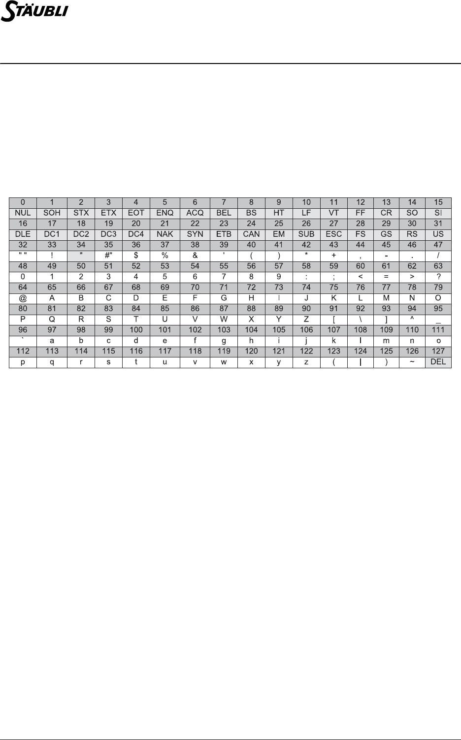
The following table gives the ASCII codes below 128. The characters in grey boxes are not supported by
the string type:
Parameter
Example
See also
num asc(string text, num position)
num Value Expression of num type
putln(chr(65)) // displays «A»

Chapter 3 - Simple types
D28062804A - 02/2006 43 / 160
num asc(string text, num position)
Syntax
num asc(<string string>, <num position>)
Function
Returns the ASCII code of the index character position.
Returns -1 if position is negative or greater than string.
Parameter
Example
See also
string chr(num Ascii Code)
string left(string string, num size)
Syntax
string left(<string string>, <num size>)
Function
Returns the first size characters of string. If size is greater than the length of string, the instruction
returns string.
An execution error is generated if size is negative.
Parameter
Example
string string Character string type expression
num position Numerical expression
putln(asc("A",0)) // displays 65
string string Character string type expression
num size Numerical expression
putln(left("hello world",5)) // displays «hello»

44 / 160 D28062804A - 02/2006
string right(string string, num size)
Syntax
string right(<string string>, <num size>)
Function
Returns the last size characters of string. If the number specified is greater than the length of string, the
instruction returns string.
An execution error is generated if size is negative.
Parameter
Example
string mid(string string, num size, num position)
Syntax
string mid(<string string>, <num size>, <num position>)
Function
Returns size characters of string from the position index character, stopping at the end of string.
An execution error is generated if size or position are negative.
Parameter
Example
string string Character string type expression
num size Numerical expression
putln(right("hello world",5)) // displays «world»
string string Character string type expression
num size Numerical expression
num position Index in the string (from 0 to 127)
putln(mid(«hello wild world»,4,6)) // displays «wild»

Chapter 3 - Simple types
D28062804A - 02/2006 45 / 160
string insert(string string, string insertion, num position)
Syntax
string insert(<string string>, <string insertion>, <num position>)
Function
Returns string in which insertion is inserted after the position index character. If position is greater than
the size of string, insertion is inserted at the end of string. The result is truncated to 128 characters.
An execution error is generated if position is negative.
Parameter
Example
string delete(string string, num size, num position)
Syntax
string delete(<string string>, <num size>, <num position>)
Function
Returns string in which size have been deleted from the position index character. If position is greater
than the length of string, the instruction returns string.
An execution error is generated if size or position are negative.
Parameter
Example
string string Character string type expression
string insertion Character string type expression
num position Index in the string (from 0 to 127)
putln(insert("hello world","wild ",6)) // displays «hello wild world»
string string Character string type expression
num size Numerical expression
num position Index in the string (from 0 to 127)
string source
source = "hello wild world"
putln(delete(source,5,6)) // displays «hello world»
putln(source) // displays «hello wild world»

46 / 160 D28062804A - 02/2006
num replace(string string, string replacement, num size, num
position)
Syntax
string replace(<string string>, <string replacement>, <num size>, <num position>)
Function
Returns string in which size characters have been replaced from the position index character by
replacement. If position is greater than the length of string, the instruction returns string.
An execution error is generated if size or position are negative.
Parameter
Example
num find(string string1, string string2)
Syntax
num find(<string string1>, <string string2>)
Function
Returns the index (between 0 and 127) of the first character in the first occurrence of string2 in string1. If
string2 does not appear in string1, the instruction returns -1.
Parameter
Example
string string Character string type expression
string replacement Character string type expression
num size Numerical expression
num position Index in the string (from 0 to 127)
putln(replace("hello ? world","wild",1,6)) // displays «hello wild world»
string string1 Character string type expression
string string2 Character string type expression
putln(find("hello wild world","wild")) // displays 6


48 / 160 D28062804A - 02/2006
3.5. DIO TYPE
3.5.1. DEFINITION
The dio type is used to link a VAL3 variable to a system on/off input/output.
The inputs/outputs declared in the system can be directly used in a VAL3 application, without having to be
declared in the application as a global or local variable. The dio type is therefore used above all to
configure a program using an input/output.
All instructions using a dio type variable not linked to an input/output declared in the system generate an
execution error.
By default, a dio type variable is not linked to a system input/output and therefore generates an execution
error if used as such in a program.
3.5.2. OPERATORS
In ascending order of priority:
bool <dio output> = <dio input/output> Assigns the input/output status to output, and
returns the status. An execution error is generated if
output is not linked to a system output.
bool <dio output> = <bool condition> Assigns condition to the output status and returns
condition. An execution error is generated if output
is not linked to a system output.
bool <dio input1> != <bool input2> Returns true if input1 and input2 do not have the
same status, otherwise returns false.
bool <dio input> != <bool condition> Returns true if the input status is not equal to
condition, otherwise returns false.
bool <dio input> == <bool condition> Returns true if the input status is equal to condition,
otherwise returns false.
bool <dio input1> == <dio input2> Returns true if input1 and input2 have the same
status, otherwise returns false.

Chapter 3 - Simple types
D28062804A - 02/2006 49 / 160
3.5.3. INSTRUCTIONS
void dioLink(dio& variable, dio source)
Syntax
void dioLink(<dio& variable>, <dio source>)
Function
Links variable to the input/output to which source is linked.
An execution error is generated if source is an input/output declared in the system.
Parameter
Example
num dioGet(dio dTable)
Syntax
num dioGet(<dio dTable>)
Function
Returns the numerical value from dTable of dio read as an integer written in binary code, i.e.: dTable[0]+2
dTable[1]+4 dTable[2]+...+2 k dTable[k], where dTable[i] = 1 if dTable[i] is true, otherwise 0.
An execution error is generated if a member of dTable is not linked to a system input/output.
Parameter
Example
See also
num dioSet(dio dTable, num Value)
dio& variable On/off input/output type variable
dio source Expression of dio type
dio dGripper1
dio dGripper2
dioLink(dGripper1, io:valve1) // links dGripper1 to valve1 system input/output
dioLink(dGripper2, dGripper1) // links dGripper2 to the dGripper1 input/output, and therefore to
valve1
dioLink(dGripper1, io:valve2) // dGripper2 is now linked to valve2, and dGripper1 is still linked
to valve1
dio nTable Expression of dio type
dio dCode[4]
dCode[0] = false
dCode[1] = true
dCode[2] = false
dCode[3] = true
putln(dioGet(dCode)) // displays 10 = 0 + 2 1 + 4 0 + 8 1

50 / 160 D28062804A - 02/2006
num dioSet(dio dTable, num Value)
Syntax
num dioSet(<dio dTable>, <num Value>)
Function
Assigns the whole part of Value in binary code to the outputs in the dTable, and returns the value actually
assigned, i.e.:
dTable[0]+2 dTable[1]+4 dTable[2]+...+2 k dTable[k], where dTable[i] = 1 if dTable[i] is true,
otherwise 0.
An execution error is generated if a member of dTable is not linked to a system output.
Parameter
Example
See also
num dioGet(dio dTable)
dio dTable Expression of dio type
num Value Expression of num type
dio dCode[4]
putln(dioSet(dCode, 10) // displays 10 = 0 + 2 1 + 4 0 + 8 1
putln(dioSet(dCode, 26) // displays 10, code is not big enough to encode 26 completely

Chapter 3 - Simple types
D28062804A - 02/2006 51 / 160
3.6. AIO TYPE
3.6.1. DEFINITION
The aio type is used to link a VAL3 variable to a system numerical input/output (integer or floating point
value).
The inputs/outputs declared in the system can be directly used in a VAL3 application, without having to be
declared in the application as a global or local variable. The aio type is therefore used above all to
configure a program using an input/output.
All instructions using a aio type variable not linked to an input/output declared in the system generate an
execution error.
By default, a aio type variable is not linked to a system input/output and therefore generates an execution
error if used as such in a program.
3.6.2. INSTRUCTIONS
void aioLink(aio& variable, aio source)
Syntax
void aioLink(<aio& variable>, <aio source>)
Function
Links variable to the input/output to which source is linked.
An execution error is generated if source is an input/output declared in the system.
Parameter
Example
num aioGet(aio input)
Syntax
num aioGet(<aio input>)
Function
Returns the numerical value of input.
An execution error is generated if input is not linked to a system input/output.
Parameter
Example
See also
num aioSet(aio output, num Value)
aio& variable aio type variable
aio source Expression of aio type
aio aSensor1
aio aSensor2
aioLink(aSensor1, io:system1) // links aSensor1 to system1 system input/output
aioLink(aSensor2, aSensor1) // links aSensor2 to the aSensor1 input/output, and therefore to
system1
aioLink(aSensor1, io:system2) // aSensor2 is now linked to system2, and aSensor1 is still
linked to system1
aio & table Expression of aio type
aio aSensor
putln(aioGet(aSensor)) // displays the current sensor value

52 / 160 D28062804A - 02/2006
num aioSet(aio output, num Value)
Syntax
num aioSet(<aio output>, <num Value>)
Function
Assigns Value to output and returns Value.
An execution error is generated if output is not linked to a system output.
Parameter
Example
See also
num aioGet(aio input)
aio& output Expression of aio type
num Value Expression of num type
aio aCommand
putln(aioSet(aCommand, -12.3)) // displays -12.3

Chapter 3 - Simple types
D28062804A - 02/2006 53 / 160
3.7. SIO TYPE
3.7.1. DEFINITION
The sio type is used to link a VAL3 variable to a serial port or an Ethernet socket connection. A sio input-
output is characterized by:
•Parameters specific to the type of communication, defined in the system
•An end of string character, to allow the use of the string type
•A communication timeout delay
The serial system inputs-outputs are active at all times. The Ethernet socket connections are activated at
the time of the initial reading or writing access by a VAL3 program. The Ethernet socket connections are
deactivated automatically when the VAL3 application is closed.
The inputs/outputs declared in the system are directly usable in a VAL3 application, without having to be
declared in the application as a global or local variable. The sio type is therefore used above all to
configure a program using an input/output.
All instructions using a sio type variable not linked to an input/output declared in the system generate an
execution error.
By default, a sio type variable is not linked to a system input/output and therefore generates an execution
error if used as such in a program.
Operators
When the communication timeout delay is reached on reading or writing the serial input/output, an
execution error is generated.
string <sio output> = <string data item> Writes successively on output the data item
characters, followed by the end of string character,
and returns data item.
num <sio output> = <num data item> Writes on output the closest integer to data item,
modulo 256, and returns the value actually sent.
num <num data item> = <sio input> Reads a character on input and assigns data item
with the ASCII code for the character.
string <string data item> = <sio input> Reads on input a string of characters and affects
data item with this string. The characters that are
not supported by the string type are ignored. The
string is completed when the end of string
character is read, or when data item reaches the
maximum size of a string (128 characters). The
end of string character is not copied into data item.

54 / 160 D28062804A - 02/2006
3.7.2. INSTRUCTIONS
void sioLink(sio& variable, sio source)
Syntax
void sioLink(<sio& variable>, <sio source>)
Function
Links variable to the serial system input/output to which source is linked.
An execution error is generated if source is an input/output declared in the system.
Parameter
Example
num clearBuffer(sio input)
Syntax
num clearBuffer(<sio input>)
Function
Empties the input reading buffer and returns the number of characters thus deleted.
For an Ethernet socket connection, clearBuffer deactivates (closes) the socket, clearBuffer returns -1 if
the socket has already been deactivated.
An execution error is generated if input is not connected to a system serial link or Ethernet socket.
num sioGet(sio input, num& data)
Syntax
num sioGet(<sio input>,<num& data>)
Function
Reads a table of characters on input and returns the number of characters read. The reading sequence
stops when the data item table is full or when the input reading buffer is empty.
For an Ethernet socket connection, sioGet tries first of all to make a connection if there is no active
connection. When the timeout for input communication has been reached, sioGet returns -1. If the
connection is active, but there are no data in the input reader buffer, sioGet waits until data are received or
until the end of the waiting period has been reached.
An execution error is generated if input is not connected to a system serial link or Ethernet socket, or if data
is not a VAL3 variable.
sio& variable sio type variable
sio source Expression of sio type
sio sSensor1
sio sSensor2
sioLink(sSensor1, io: serial1) // links sSensor1 to serial1 system input/output
sioLink(sSensor2, sSensor1) // links sSensor2 to the sSensor1 input/output, and therefore to
serial1
sioLink(sSensor2, io: serial1) // links sSensor2 to serial1, sSensor1 is still linked to
serial1

Chapter 3 - Simple types
D28062804A - 02/2006 55 / 160
num sioSet(sio output, num& data)
Syntax
num sioSet(<sio output>,<num& data>)
Function
Writes a table of characters on output and returns the number of characters written. Numerical values are
converted before transmission into integers between 0 and 255, taking the nearest integer modulo 256.
For an Ethernet socket connection, sioSet tries first of all to make a connection if there is no active
connection. When the end of the output communication waiting time has been reached, sioSet returns -1.
The number of characters written can be less than the size of data if a communication error is detected.
An execution error is generated if output is not connected to a system serial link or Ethernet socket.


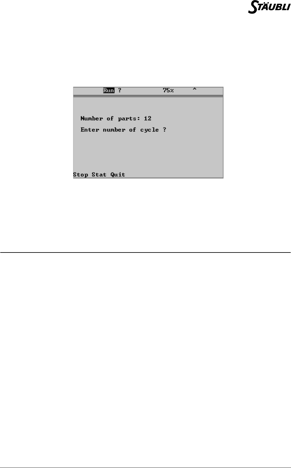
Chapter 4 - User interface
D28062804A - 02/2006 59 / 160
4.1. USER PAGE
In the VAL3 language, the user interface instructions are used to:
-display messages on a page of the manual control pendant (MCP) reserved for the application
-acquire keystrokes on the MCP keyboard
User page
The user page has fourteen (14) 40-column lines. The last line can be used to create menus with the
associated key. An additional line is available for a title display.
4.2. INSTRUCTIONS
void userPage(), void userPage(bool fixed)
Syntax
void userPage ()
void userPage (<bool fixed>)
Function
Displays the user page on the MCP screen.
If the parameter fixed is true, only the user page is accessible for the operator, except for the profile
changing page that is accessible via the "Shift User" keyboard shortcut. When this page is displayed, it is
possible to stop the application using the "Stop" key if the current user profile authorizes the action.
If the parameter is false, the other CS8 pages become accessible again.

60 / 160 D28062804A - 02/2006
void gotoxy(num x, num y)
Syntax
void gotoxy(<num x>, <num y>)
Function
Positions the cursor at the (x, y) coordinates on the user page. The coordinates of the top left-hand corner
are (0,0) and those of the bottom right-hand corner are (39, 13).
The x abscissa is taken modulo 40. The y ordinate is taken modulo 14.
Parameter
See also
void cls()
void cls()
Syntax
void cls()
Function
Clears the user page and sets the cursor to (0,0).
See also
void gotoxy(num x, num y)
void put() void putln()
Syntax
void put(<string string>)
void put(<num Value>)
void putln(<string string>)
void putln(<num Value>)
Function
Displays the specified string or Value (to 3 decimal places) at the cursor position on the user page. The
cursor is then positioned on the character after the last character of the message displayed (put
instruction), or on the first character of the next line (putln instruction).
At the end of a line, the display continues on the following line.
At the end of a page, the user page display moves up one line.
Parameter
See also
void popUpMsg(string string)
void logMsg(string string)
void title(string string)
num x Cursor abscissa (0 to 39)
num y Cursor ordinate (0 to 13)
string string Character string type expression
num Value Numerical expression

Chapter 4 - User interface
D28062804A - 02/2006 61 / 160
void title(string string)
Syntax
void title(<string string>)
Function
Changes the title of the user page.
The title() instruction does not change the current cursor position.
Parameter
num get()
Syntax
num get(<string& string>)
num get(<num& Value>)
num get()
Function
Acquires a string, a number or a control panel key.
string or Value are displayed at the current cursor position and can be changed by the user. The entry is
terminated by pressing a menu key or the Return or Esc keys.
The instruction returns the code of the key used to end the entry.
Pressing Return or a menu key updates the string or Value variable. Pressing Esc does not change the
variable.
If no parameter is passed, the get() instruction waits for the operator to press any key and returns the key
code. The key that has been pressed is not displayed.
In all cases, the current position of the cursor is unaffected by the get() instruction.
Menus (with or without Shift):
string string Character string type expression
Without Shift With Shift
3Caps Space 3Caps Space
283 - 32 Move 283 - 32 Move
Ret. -Ret. -
2Shift Esc Help Run 2Shift Esc Help Run
282 - 255 - 270 - 282 - 255 - 270 -
Menu Tab Up Bksp Stop Menu UnTab PgUp Bksp Stop
- 259 261 263 - - 260 262 263 -
1User Left Down Right 1User Home PgDn End
281 - 264 266 268 281 - 265 267 269
F1 F2 F3 F4 F5 F6 F7 F8
271 272 273 274 275 276 277 278

62 / 160 D28062804A - 02/2006
For standard keys, the code returned is the ASCII code of the corresponding character:
Parameter
Example
See also
num getKey()
Without Shift
q w e r t y u i o p
113 119 101 114 116 121 117 105 111 112
a s d f g h j k l <
97 115 100 102 103 104 106 107 108 60
z x c v b n m . , =
122 120 99 118 98 110 109 46 44 61
With Shift
7 8 9 + * ; ( ) [ ]
55 56 57 43 42 59 40 41 91 93
4 5 6 - / ? : ! { }
52 53 54 45 47 63 58 33 123 125
1 2 3 0 " % - . , >
49 50 51 48 34 37 95 46 44 62
With double Shift
Q W E R T Y U I O P
81 87 69 82 84 89 85 73 79 80
A S D F G H J K L }
65 83 68 70 71 72 74 75 76 125
Z X C V B N M $ \ =
90 88 67 86 66 78 77 36 92 61
string& string string type variable
num& Value num type variable
num nValue
num nKey
// Waits for Return to be pressed to confirm the entry
do
nKey = get (nValue)
until (nKey == 270)

Chapter 4 - User interface
D28062804A - 02/2006 63 / 160
num getKey()
Syntax
num getKey()
Function
Acquires a key stroke from the control panel keyboard. Returns the code of the last key pressed since the
last getKey() call, or -1 if no key has been pressed since then.
Unlike the get() instruction, getKey() returns immediately.
The key pressed is not displayed and the current cursor position stays unchanged.
Example
See also
num get()
bool isKeyPressed(num code)
bool isKeyPressed(num code)
Syntax
bool isKeyPressed(<num code>)
Function
Returns the status of the key specified by its code (see get()), true if the key is pressed, otherwise false.
See also
num getKey()
void popUpMsg(string string)
Syntax
void popUpMsg(<string string>)
Function
Displays string in a "popup" window above the current MCP window. This window remains displayed
until it is confirmed by clicking on Ok in the menu or pressing the Esc key.
See also
void userPage(), void userPage(bool fixed)
void put() void putln()
// Displays the system clock until any key is pressed
getKey() // Resets the code of the last key pressed
while (getKey()== -1)
gotoxy(0,0)
put(toString(«», clock()* 10))
endWhile

64 / 160 D28062804A - 02/2006
void logMsg(string string)
Syntax
void logMsg(<string string>)
Function
Writes string in the system history. The message is saved with the current date and time.
See also
void popUpMsg(string string)
string getProfile()
Syntax
string getProfile()
Function
Returns the name of the current user profile.


Chapter 5 - Tasks
D28062804A - 02/2006 67 / 160
5.1. DEFINITION
A task is a program that is running.
An application typically contains an arm movement task, an automaton task, a user interface task, a safety
signal monitoring task, communication tasks, etc..
A task is defined by the following elements:
•a name: a task identifier that is unique in the library or application
•a priority, or a period: a task sequencing parameter
•a program: a task entry (and exit) point
•a status: running or stopped
•the next instruction to be executed (and its context)
5.2. RESUMING AFTER AN EXECUTION ERROR
When an instruction causes an execution error, the task is stopped. The taskStatus() instruction is used to
diagnose the execution error. The task can then be resumed via the taskResume() instruction. If the
execution error can be corrected, the task can resume from the instruction line where it was stopped.
Otherwise, it must be restarted from before or after that instruction line.
Starting and stopping the application
When an application starts, its start() program is executed in a task with the name of the application
followed by ’~’, and with priority 10.
When an application stops, its stop() program is executed in a task with the name of the application
preceded by ’~’, priority 10.
If a VAL3 application is stopped via the CS8 user interface, the start task, if it still exists, is immediately
destroyed. The stop() program is run next, and then any remaining application tasks are deleted in the
reverse order to that in which they were created.
5.3. VISIBILITY
A task is visible only from within the program or library that created it. The instructions taskSuspend(),
taskResume(), taskKill() and taskStatus() act on a task created by another library as if the task was not
created. Two different libraries may therefore create tasks with the same name.
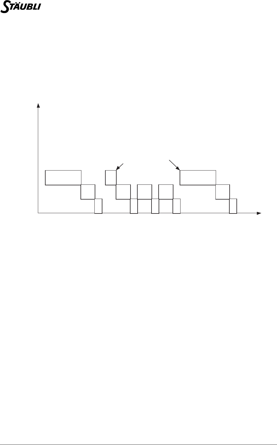
68 / 160 D28062804A - 02/2006
5.4. SEQUENCING
When several tasks of an application are running, they appear to run concurrently and independently. This
is true if the whole application is observed over a sufficiently long period of time (about a second), but not
true if its specific behaviour is examined over a short period of time.
In fact, as the system has only one processor, it can only execute one task at a time. Simultaneous
execution is simulated by very fast sequencing of the tasks that execute a few instructions in turn before
the system moves on to the next task.
Sequencing
VAL3 task sequencing obeys the following rules:
1. The tasks are sequenced in the order in which they were created
2. During each sequence, the system attempts to execute a number of VAL3 instruction lines
corresponding to the priority of the task.
3. When an instruction line cannot be terminated (execution error, waiting for a signal, task stopped,
etc.) the system moves on to the next VAL3 task.
4. When all VAL3 tasks have been completed, the system keeps some free time for lower priority
system tasks (such as network communication, user screen refresh, file access), before a new
cycle is started.
The maximum delay between two sequential cycles is equal to the duration of the last sequencing
cycle; but, most of the time, this delay is null because the system does not need it.
The VAL3 instructions that can cause a task to be sequenced immediately are as follows:
• watch() (condition wait timeout)
• delay() (timeout)
•wait() (condition waiting time)
• waitEndMove() (arm stop waiting time)
• open() and close() (arm stop waiting time followed by timeout)
•get() (keystroke waiting time)
•taskResume() (waits until the task is ready for restart)
•taskKill() (waits for the task to be actually killed)
•disablePower() (waits for power to be actually cut off)
•The instructions accessing the contents of the disk (libLoad, libSave, libDelete, libList)
•The sio reading/writing instructions (operator =, sioGet(), sioSet())
•setMutex() (waits for the Boolean mutex to be false)
T2
T1
T2
T3
T2 T2
T1
T3 T3 T3
T2
T3
T1
T1 execute
delay() function waiting time
priority
time
S5.3

Chapter 5 - Tasks
D28062804A - 02/2006 69 / 160
5.5. SYNCHRONOUS TASKS
The sequence described above is the sequence of normal tasks, called asynchronous tasks, that are
scheduled by the system so that they execute as fast as possible. It is sometimes necessary to schedule
tasks at regular periods of time, for data acquisition or device control: such tasks are called synchronous
tasks.
They are executed in the sequencing cycle by interrupting the asynchronous task between two VAL3 lines.
When the synchronous tasks have finished, the asynchronous task resumes.
The sequencing of the VAL3 synchronous tasks obeys the following rules:
1. Each synchronous task is sequenced exactly once per period of time specified at the task creation
(for instance, once every 4ms).
2. At each sequence, the system executes up to 3000 VAL3 instruction lines. It shifts to the next task
when an instruction line cannot be completed immediately (runtime error, waiting for a signal, task
stopped, ...).
In practice, a synchronous task is often explicitly ended by using the "delay(0)" instruction to force
the sequencing of the next task.
3. The synchronous tasks with same period are sequenced in the order in which they were created.
5.6. OVERRUN
If the execution of a VAL3 synchronous task takes longer than the specified period, the current cycle ends
normally, but the next cycle is cancelled. This overrun error is signalled to the VAL3 application by setting
the Boolean variable specified for this purpose at the task creation to "true". At the beginning of each cycle
this Boolean variable thus shows whether the previous sequencing was carried out entirely or not.
5.7. INPUTS / OUTPUTS REFRESH
Inputs are refreshed before both the synchronous tasks and the asynchronous tasks. In the same way,
outputs are refreshed after both the synchronous tasks and the asynchronous tasks.
WARNING:
It is not possible to specify which inputs / outputs are used by one task. As a
consequence, each refresh is performed on all inputs / outputs.
The refresh of inputs / outputs on Modbus, BIO board, MIO board, CIO board or AS-i
bus are not controlled by the VAL3 scheduler. They can be refreshed at any time during
the sequencing of a VAL3 task.
S5.3

70 / 160 D28062804A - 02/2006
5.8. SYNCHRONIZATION
It is sometimes necessary to synchronize several tasks before they are executed.
If the amount of time required to execute each of the tasks is known beforehand, they can be synchronized
by simply waiting for a signal generated by the slowest task. However, if it is not known which task is the
slowest, it is necessary to use a more complex synchronizing mechanism for which an example of VAL3
programming is shown below.
Example
// synchronization of control for global variables
num n
bool bSynch
n=0 // Initialization of the global datas
bSynch=false
program Task1()
begin
while(true)
call synchro(n, bSynch, 2) // Synchronization with task 2
<instructionsTask1>
endWhile
end
program Task2()
begin
while(true)
call synchro(n, bSynch, 2) // Synchronization with task 1
<instructionsTask2>
endWhile
end
// Synchronization program for N tasks
program synchro(num& n, bool& bSynch, num N)
begin
n = n + 1
wait((n==N) or (bSynch==true)) // Task synchronization waiting time
bSynch = true
n = n - 1
wait((n==0) or (bSynch == false)) // Task release waiting time
bSynch = false
end

Chapter 5 - Tasks
D28062804A - 02/2006 71 / 160
5.9. SHARING RESOURCES
When several tasks use the same system or cell resource (global datas, screen, keyboard, robot, etc.) it is
importent to ensure that there is no conflict between them.
A mutual exclusion (’mutex’) mechanism that protects a resource by allowing it to be accessed by only
one task at a time can be used for this purpose. An example of mutex programming in VAL3 is shown
below.
Example
bool bScreen
bScreen= false // Initialization: screen resource is free
program Task1()
begin
while(true)
setMutex(bScreen) // Screen resource requested
call fillScreen(1)
bScreen = false // Screen resource released
delay(0) // Proceeds to the next task
endWhile
end
program Task2()
begin
while(true)
setMutex(bScreen) // Screen resource requested
call fillScreen(2)
bScreen = false // Screen resource released
delay(0) // Proceeds to the next task
endWhile
end
// program to fill the screen with the digit i
program fillScreen(num i)
num x
num y
begin
i = i % 10
for x = 0 to 39
for y = 0 to 13
gotoxy(x, y)
put(i);
endFor
endFor
end

72 / 160 D28062804A - 02/2006
5.10. INSTRUCTIONS
void taskSuspend(string name)
Syntax
void taskSuspend(<string name>)
Function
Suspends execution of the name task.
If the task is already STOPPED, the instruction has no effect.
An execution error is generated if name does not correspond to any VAL3 task, or corresponds to a VAL3
task created by another library.
Parameter
See also
void taskResume(string name, num skip)
void taskKill(string name)
void taskResume(string name, num skip)
Syntax
void taskResume (<string name>, <num skip>)
Function
Resumes execution of the name task on the line located skip instruction lines before or after the current
line.
If skip is negative, the program resumes before the current line. If the task status is not STOPPED, the
instruction has no effect.
An execution error is generated if name does not correspond to a VAL3 task, corresponds to a VAL3 task
created by another library, or if there is no instruction line at the specified skip.
Parameter
See also
void taskSuspend(string name)
void taskKill(string name)
string name Character string type expression
string name Character string type expression
num skip Numerical expression

Chapter 5 - Tasks
D28062804A - 02/2006 73 / 160
void taskKill(string name)
Syntax
void taskKill (<string name>)
Function
Suspends and then deletes the name task. When the instruction has been executed, the name task is no
longer present in the system.
If there is no name task, or if the name task was created by another library, the instruction has no effect.
Parameter
See also
void taskSuspend(string name)
void taskCreate string name, num priority, program(...)
void setMutex(bool& mutex)
Syntax
void setMutex(<bool& bMutex>)
Function
Wait for the bMutex variable to be false, then set it to true.
This function is required to use a Boolean variable as a mutual exclusion mechanism for protecting shared
resources (see chapter 5.9).
string name Character string type expression

74 / 160 D28062804A - 02/2006
num taskStatus(string name)
Syntax
num taskStatus (<string name>)
Function
Returns the current status of the name task, or the task execution error code if the latter is in error
condition:
Code Description
-1 There is no task name created by the current library or application
0No execution error
1A task is running
10 Invalid numerical calculation (division by zero).
11 Invalid numerical calculation (e.g.ln(-1))
20 Access to a table with an index that is larger than the table size.
21 Access to a table with a negative index.
29 Invalid task name. See taskCreate() instruction.
30 The specified name does not correspond to any VAL3 task.
31 A task with the same name already exists. See taskCreate instruction.
32 Only 2 different periods for synchronous tasks are supported. Change scheduling period.
40 Not enough memory space available.
41 Not enough memory space to run the task. See the run memory size.
60 Maximum instruction run time exceeded.
61 Internal VAL3 interpreter error
70 Invalid instruction parameter. See the corresponding instruction.
80 Uses data or a program from a library not loaded in the memory.
81 Incompatible kinematic: Use of a point/joint/config that is not compatible with the arm kinematic.
90 The task cannot resume from the location specified. See taskResume() instruction.
100 The speed specified in the motion descriptor is invalid (negative or too great).
101 The acceleration specified in the motion descriptor is invalid (negative or too great).
102 The deceleration specified in the motion descriptor is invalid (negative or too great).
103 The sideways speed specified in the motion descriptor is invalid (negative or too great).
104 The rotation speed specified in the motion descriptor is invalid (negative or too great).
105 The reach parameter specified in the movement descriptor is invalid (negative).
106 The leave parameter specified in the movement descriptor is invalid (negative).
122 Attempt to write in a system input.
123 Use of a dio, aio or sio input/output not connected to a system input/output.
124 Attempt to access a protected system input/output
125 Read or write error on a dio, aio or sio (field bus error)
150 Cannot run this movement instruction: a previous movement request could not be completed (point out
of reach, singularity, configuration problem, etc.)
153 Movement command not supported
154 Invalid movement instruction: check the movement descriptor.
160 Invalid flange tool coordinates
161 Invalid world tool coordinates
162 Use of a point without a reference frame. See Definition.
163 Use of a frame without a reference frame. See Definition.
164 Use of a tool without reference tool. See Definition.
165 Invalid frame or reference tool (global variable linked to a local variable)
250 No runtime licence for this instruction, or demo licence is over.

Chapter 5 - Tasks
D28062804A - 02/2006 75 / 160
Parameter
See also
void taskResume(string name, num skip)
void taskKill(string name)
void taskCreate string name, num priority, program(...)
Syntax
void taskCreate <string name>, <num priority>, program([p1] [,p2])
Function
Creates and starts up the name task.
name must contain 1 to 15 characters selected from "a..zA..Z0..9_". There must not be another task with
the same name created by the same library.
Execution of name begins with a call to program using the parameters specified. It is not possible to use a
local variable for a parameter passed by reference.
The task ends by default with the last instruction line of program, or earlier, if it is deleted explicitly.
priority must be between 1 and 100. When the task is sequenced, the system executes a number of
instruction lines corresponding to the priority, or fewer if a blocking instruction is encountered (see the
chapter entitled Sequencing).
An execution error is generated if the system does not have enough memory to create the task, if name is
not valid or already in use in the same library, or if priority is not valid.
Parameter
Example
See also
void taskSuspend(string name)
void taskKill(string name)
num taskStatus(string name)
string name Character string type expression
string name Character string type expression
num priority Numerical expression
program Name of an application program
p1 Type of expression specified by the program
program display(string& sText)
begin
putln(sText)
sText = "stop"
end
string sMessage
program start()
begin
sMessage = "start"
taskCreate "t1", 10, display(sMessage) // displays « start »
wait(taskStatus("t1") == -1) // waits for the end of t1
putln(sMessage) // displays "stop"
end

76 / 160 D28062804A - 02/2006
void taskCreateSync string name, num period, bool& overrun,
program(...)
Syntax
void taskCreateSync <string name>, <num period>, <bool& overrun>, program(...)
Function
Creates and starts a synchronous task.
The execution of the task starts with the call of the specified program with the specified parameters.
A runtime error is generated if the system does have not enough memory to create the task, or if one or
more parameters are invalid.
For a detailed description of synchronous tasks (see chapter 5.5).
Parameter
Example
// Create a supervisor task scheduled every 20 ms
taskCreateSync "supervisor", 0.02, bSupervisor, supervisor()
string name Name of the task to create. It must contain 1 to 15 characters
selected from "_a..zA..Z0..9". There cannot be another task with
the same name belonging to the same application or library.
num priority Period of the task to create (s). The specified value is rounded
down to a multiple of 4ms. Any positive period is supported, but
the system supports only two different periods of synchronous
tasks at the same time.
bool& overrun Boolean variable to signal overrun errors. Only global variables are
supported, to make sure that the variable is not deleted before the
task.
program Name of the VAL3 program to call when the task is started, with its
parameters between parenthesis. It is not possible to use a local
variable as parameter if it is passed by reference, to make sure that
the variable is not deleted before the task.
S5.3

Chapter 5 - Tasks
D28062804A - 02/2006 77 / 160
void wait(bool condition)
Syntax
void wait(<bool condition>)
Function
Puts the current task on hold until condition is true.
The task remains RUNNING during the waiting time. If condition is true at the first evaluation, the task in
question is executed immediately (the next task is not sequenced).
Parameter
See also
void delay(num seconds)
bool watch(bool condition, num seconds)
void delay(num seconds)
Syntax
void delay(<num seconds>)
Function
Puts the current task on hold for seconds.
The task remains RUNNING during the waiting time. If seconds is negative or null, the system sequences
the next VAL3 task immediately.
Parameter
See also
num clock()
bool watch(bool condition, num seconds)
bool condition Boolean expression
num seconds Numerical expression

78 / 160 D28062804A - 02/2006
num clock()
Syntax
num clock()
Function
Returns the current value of the internal system clock expressed in seconds.
The internal system clock is accurate to within one millisecond. It is initialized at 0 when the controller is
started up and is thus unrelated to calendar time.
Example
num nStart
nStart=clock()
<instructions>
put("time required for the operation= " )
putln(clock()-nStart)
See also
void delay(num seconds)
bool watch(bool condition, num seconds)
bool watch(bool condition, num seconds)
Syntax
bool watch (<bool condition>, <num seconds>)
Function
Puts the current task on hold until condition is true or seconds seconds have elapsed.
Returns true if the waiting time ends when condition is true, otherwise returns false when the waiting
time ends because the time has expired.
The task remains RUNNING during the waiting time. If condition is true at the first evaluation, the same
task is evaluated immediately, otherwise the system sequences the other VAL3 tasks (even if seconds is
up to and including 0).
Parameter
Example
while (watch (dSensor, 20)) == false
popUpMsg("Waiting for part")
endWhile
See also
void delay(num seconds)
void wait(bool condition)
num clock()
bool condition Boolean expression
num seconds Numerical expression


Chapter 6 - Libraries
D28062804A - 02/2006 81 / 160
6.1. DEFINITION
A VAL3 library is a software application that can be reused by an application or by other VAL3 libraries.
Like an ordinary application, a VAL3 library comprises the following components:
-a set of programs: the VAL3 instructions to be executed
-a set of global datas: the library data
-a set of libraries: the external instructions and data used by the library
When a library is being run, it can also contain:
-a set of tasks: The programs that are specific to the library being run
The format used to save the library is the same as that of a VAL3 application. All applications can be used
as a library and all libraries can be used as an application, if the start() and stop() programs are defined in
them.
6.2. INTERFACE
A library's global programs and datas are either public or private. Only global programs and datas that are
public are accessible outside the library. Private programs and global datas can only be used by the library
programs.
All the public global programs and datas from a library form its interface: a number of different libraries can
have the same interface, as long as their public programs and data take the same names.
The tasks created by a library program are always private, i.e. they can only be accessed by that library.
6.3. INTERFACE IDENTIFIER
To use a library, an application needs to first declare an identifier assigned to it, and then request, in a
program, that the library be loaded into the memory under that identifier.
The identifier is assigned to the library interface and not to the library itself. Any library presenting the
same interface can then be loaded under that identifier. This mechanism can be used, for example, to
define a library for every possible part of an application, and then load only the part processed by each
cycle.
6.4. CONTENT
A library does not have any required content: it can contain only programs, or only data, or both.
Library content is accessed by writing the identifier's name followed by ’:’ in front of the name of the library
program or data, for example:
Accessing the content of a library that has not yet been loaded into the memory causes an execution error.
part:libLoad("part_7") // Loads the "part_7" library identified as ’part’
title(part:name) // Displays as title the content of the name variable of the "part_7" library
call part:init() // Calls up the init() program for the current part

82 / 160 D28062804A - 02/2006
6.5. LOADING AND UNLOADING
When a VAL3 application is open, all the libraries declared are analysed to build the corresponding
interfaces. This step does not load the libraries into the memory.
When a library is loaded, its global datas are initialized and its programs checked to detect any syntax
errors.
It is not necessary to unload a library, this is done automatically when the application ends, or when a new
library is loaded to replace another one.
When a VAL3 application is stopped via the CS8 user interface, the stop() program is run first, then all the
application tasks, and its libraries, if any are left, are destroyed.
Access path
The libLoad(), libSave() and libDelete() instructions use a library access path, specified as a character
string. An access path comprises an (optional) root, an (optional) path and a library name, in the following
format:
root://path/name
The root specifies the file medium: "Floppy" for a diskette, "USB0" for a device on a USB port (stick,
floppy driver), "Disk" for a version saved on the CS8, or the name of an Ftp connection defined on the
CS8 for a network access.
By default, the root is "Disk" and the path is blank.
Example
part:libLoad("part_1")
part:libSave("Floppy://part")
part:libSave("Disk://part_x/part_1")
Error codes
The VAL3 library handling functions never generate execution errors but they send back an error code
used to check the instruction result and troubleshoot any problems that may arise.
Code Description
0No error
10 The library identifier has not been initialized by libLoad().
11 Cannot load the library: its interface does not correspond to that of the identifier.
12 Cannot load the library: the library contains invalid data or programs.
13 Cannot unload the library: the library contains invalid data or programs.
20 File access error: invalid path root.
21 File access error: invalid path.
22 File access error: invalid name.
30 File reading/writing error.
31 During writing: the path specified already contains a library.
During reading: another identifier is already using this library.

Chapter 6 - Libraries
D28062804A - 02/2006 83 / 160
6.6. INSTRUCTIONS
num identifier:libLoad(string path)
Syntax
num identifier:libLoad(string path)
Function
Initializes the library identifier by loading the library program and data into the memory following the
specified path.
Returns a 0 after loading, a library loading error code if there are still tasks running that were created by
the library, if the library access path is invalid, if the library contains syntax errors or if the library specified
does not correspond to the interface declared for the identifier.
See also
num identifier:libSave(), num libSave()
num identifier:libSave(), num libSave()
Syntax
num identifier:libSave()
num identifier:libSave(string path)
Function
Saves the data and programs assigned to the library's identifier. If libSave() is called without an identifier,
the application of the library calling is saved. If a parameter is specified, the content is saved via the
specified path. Otherwise, the content is saved via the path specified on loading.
Returns a 0 if the content has been saved, a library error code if the identifier has not been initialized, if the
path is invalid, if a writing error occurs or if the path specified already contains a library.
See also
num libDelete(string path)
num libDelete(string path)
Syntax
num libDelete(string path)
Function
Deletes the library located in the specified path.
Returns 0 if the specified library does not exist or has been deleted, and a library error code if the identifier
has not been initialized, if the path is invalid or if a writing error occurs.
See also
num identifier:libSave(), num libSave()
string identifier:libPath(), string libPath()

84 / 160 D28062804A - 02/2006
string identifier:libPath(), string libPath()
Syntax
string identifier:libPath()
Function
Sends the access path of the library associated with the identifier, or that of the application or library calling
if no identifier is specified.
See also
bool libList(string path, string& contents)
bool libList(string path, string& contents)
Syntax
bool libList(string path, string& contents)
Function
Lists the contents of the path specified in the contents table. Returns true if the contents table lists the
full result, and false if the table is too small to hold the full list.
All elements of the contents table are first initialized to "" (empty string). After libList() is executed, the end
of the list is therefore found by searching the first empty string in the contents table.
If contents is a global variable, it is automatically incremented as required to enable storage of the full
result.
See also
string identifier:libPath(), string libPath()


Chapter 7 - Robot control
D28062804A - 02/2006 87 / 160
This chapter lists the instructions that allow access to the status of the various parts of the robot.
7.1. INSTRUCTIONS
void disablePower()
Syntax
void disablePower()
Function
Cuts off the power supply to the arm and waits until the power supply has actually been cut off.
If the arm is moving, it stops abruptly on its trajectory before the power is switched off.
See also
void enablePower()
bool isPowered()
void enablePower()
Syntax
void enablePower()
Function
In remote mode, switches the arm power on.
This instruction does not have any effects in local, manual or test modes, or when the power supply is
being switched off.
Example
// Switches on the power and waits for the arm power to be switched on
enablePower()
if(watch(isPowered(), 5) == false)
putln("The power supply cannot be switched on")
endIf
See also
void disablePower()
bool isPowered()
bool isPowered()
Syntax
bool isPowered()
Function
Returns the power status of the arm:
true: the arm is under power
false: the arm power is switched off, or is being switched on or off

88 / 160 D28062804A - 02/2006
bool isCalibrated()
Syntax
bool isCalibrated()
Function
Returns the recovery system status of the robot:
true: all the robot axis are calibrated
false: at least one robot axis is not calibrated
num workingMode(), num workingMode(num& status)
Syntax
num workingMode (num& status)
num workingMode()
Function
Returns the current working mode of the robot:
Parameter
Mode Stat
us Operating mode Status
00Invalid or transitional -
1
0
Manual
Programmed movement
1Connection movement
2Revolute (Joint)
3Cartesian (Frame)
4 (Tool)
5To point (Point)
6Hold
2
0
Test
Programmed movement (250 mm/s)
1Connection movement (250 mm/s)
2Fast programmed movement
3Hold
3
0
Local
Move (programmed movement)
1Move (connection movement)
2Hold
4
0
Remote
Move (programmed movement)
1Move (connection movement)
2Hold
num& status Numerical type variable.

Chapter 7 - Robot control
D28062804A - 02/2006 89 / 160
num speedScale()
Syntax
num speedScale()
Function
Returns the current monitor speed.
Example
num nCycle
taskCreate "checkSpeed", 5, checkSpeed()
program checkSpeed()
begin
while true
if(nCycle < 2)
if (speedScale()> 10)
stopMotion()
putln("For the first cycle the monitor speed must remain at 10%")
wait(speedScale()<= 10)
restartMotion()
endIf
endIf
endWhile
end
num esStatus()
Syntax
num esStatus()
Function
Returns the status of the E-Stop circuit:
See also
num workingMode(), num workingMode(num& status)
Code Status
0All the E-Stops are inactive.
1Waiting for validation after an emergency stop.
2E-Stop open.


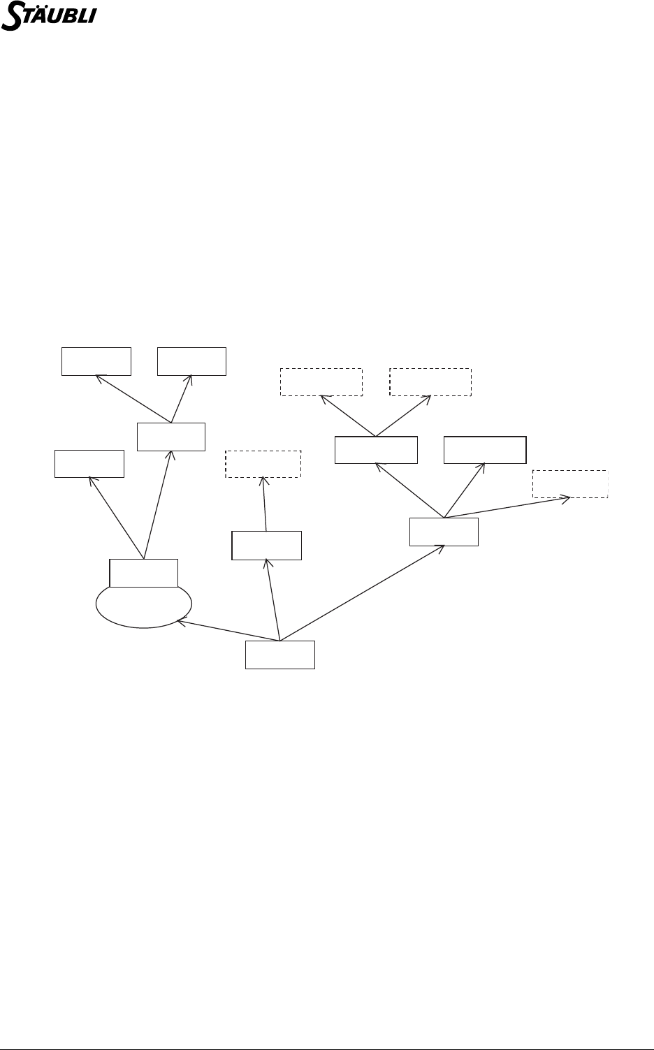
92 / 160 D28062804A - 02/2006
8.1. INTRODUCTION
This chapter describes the VAL3 data types used to program the arm positions used in a VAL3
application.
Two position types are defined in VAL3: revolute positions (joint type) that give the angular position of
each axis, and Cartesian points (point type) that give the Cartesian position of the tool at the end of the
arm.
The tool type describes a tool and its geometry used to position and control the speed of the arm; it
describes also how to activate the tool (trigger, delay).
The frame type describes a geometrical frame. The use of frames makes geometrical point manipulation
much simpler and more intuitive.
The trsf type describes a geometrical transformation. It is used implicitly by the tool, point and frame
types.
Finally, the config type describes the more advanced concept of arm configuration.
The relationships between these various types can be summarized as follows:
Organization chart: frame / point / tool / trsf
8.2. JOINT TYPE
8.2.1. DEFINITION
A revolute point (joint type) defines the angular position of each robot axis.
The joint type is a structured type, with the following fields, in this order:
These fields are expressed in degrees for the rotary axes, and in millimetres for the linear axes. The origin
of each axis is defined by the type of arm used.
By default, each field of a joint type variable is initialized at the value 0.
num j1 Revolute position of axis 1
num j2 Revolute position of axis 2
num j3 Revolute position of axis 3
num j... Revolute position of axis ... (one field for each axis)
world
frame f1
frame f2
frame f21 frame f21
point p1a
point p21a point p21b
point p2a
Trsf
Trsf
Trsf Trsf Trsf
Trsf
Trsf
Trsf
tool t1
robot
tool t2
Trsf Trsf
tool t21 tool t22
Trsf Trsf
flange

Chapter 8 - Arm positions
D28062804A - 02/2006 93 / 160
8.2.2. OPERATORS
In ascending order of priority:
8.2.3. INSTRUCTIONS
joint abs(joint jPosition)
Syntax
joint abs(joint jPosition)
Function
Returns the absolute value of a joint position, field by field.
Parameter
Details
The absolute value of a joint, with the ">" or "<" joint operators, is useful to compute easily a distance
between a joint position and a reference position.
Example
jReference = {90, 45, 45, 0, 30, 0}
jMaxDistance = {5, 5, 5, 5, 5, 5}
j = herej()
// Checks that all the axis are less than 5 degrees from the reference
if(!(abs(j - jReference) < jMaxDistance))
popUpMsg("Move closer to the marks")
endIf
See also
Operator < (joint)
Operator > (joint)
joint <joint& position1> = <joint position2> Assigns position2 to the position1 variable field by
field and returns position2.
bool <joint position1> != <joint position2> Returns true if a position1 field is not equal to the
corresponding position2 field, to within the accuracy
of the robot, otherwise it returns false.
bool <joint position1> == <joint position2> Returns true if each position1 field is equal to the
corresponding position2 field, to within the accuracy
of the robot, otherwise it returns false.
bool <joint position1> > <joint position2> Returns true if each position1 field is greater than
the corresponding position2 field, otherwise it
returns false.
bool <joint position1> < <joint position2> Returns true if each position1 field is less than the
corresponding position2 field, otherwise it returns
false.
Caution: position1 > position2 is not strictly
identical to position2 < position1!
joint <joint position1> - <joint position2> Returns the difference, field by field, between
position1 and position2.
joint <joint position1> + <joint position2> Returns the sum, field by field, of position1 and
position2.
jPosition Joint expression

94 / 160 D28062804A - 02/2006
joint herej()
Syntax
joint herej()
Function
Return the current arm joint position.
Details
The returned value is the position sent to the amplifiers by the controller, and not the position read from the
axis encoders. The controller joint position is refreshed every 4ms.
Example
// Wait until the arm is near the reference position, with timeout
bStart = watch(abs(herej() - jReference) < jMaxDistance, 60)
if bStart==false
popUpMsg("Move closer to the start position")
endIf
See also
point here(tool tTool, frame fFrame)
bool getLatch(joint& jPosition) (CS8C only)
bool isInRange(joint jPosition)
bool isInRange(joint jPosition)
Syntax
bool isInRange(joint jPosition)
Function
Test if a joint position is within the software joint limits of the arm.
Parameter
Details
When the arm is out of the software joint limits (after a maintenance operation), it is not possible to move
the arm with a VAL3 application, only manual moves are possible (with limited move directions).
Example
// Check if the current position is within the joint limits
if isInRange(herej())==false
putln("Please place the arm within its workspace")
endIf
See also
joint herej()
jPosition Joint expression to be tested

Chapter 8 - Arm positions
D28062804A - 02/2006 95 / 160
void setLatch(dio input) (CS8C only)
Syntax
void setLatch(dio input)
Function
Enable robot position latch on the next rising edge of the input signal.
Parameter
Details
The robot position latching is a hardware feature that is supported only by the fast inputs of the CS8C
controller (io:fIn0, io:fIn1).
The detection on the rising edge of the input signal is guaranteed only if the signal remains low during at
least 0.2 ms before the rising edge, and high during at least 0.2 ms after the rising edge.
A runtime error is generated is the specified digital input does not support robot position latching.
Example
// enable latch on first fast input (CS8C)
setLatch(io:fIn0)
See also
bool getLatch(joint& jPosition) (CS8C only)
input Dio expression defining the digital input to be used for latching
CAUTION:
The latch is enabled only after some time (between 0 and 0.2 ms) after the setLatch
instruction is executed. You may need to add a delay(0) instruction after setLatch to
make sure the latch is effective before the next VAL3 instruction is executed.
S5.3

96 / 160 D28062804A - 02/2006
bool getLatch(joint& jPosition) (CS8C only)
Syntax
bool getLatch(joint& jPosition)
Function
Read the last latched robot position.
Parameter
Details
The function returns true if there is a valid latched position to read. If a latch is pending, or if latching has
never been enabled, the function returns false and the position is not updated.
getLatch returns the same latched position until a new latch is enabled with the setLatch instruction.
The arm position is refreshed in the CS8C controller every 0.2 ms; the latched position is the position of
the arm between 0 and 0.2 ms after the rising edge of the fast input.l
Example
// Wait for a latched position during 5 seconds.
bLatch = watch(getLatch(jPosition)==true, 5)
if bLatch==true
putln("Successful position latch")
else
putln("No latch signal was detected")
endif
See also
void setLatch(dio input) (CS8C only)
joint herej()
jPosition Joint expression defining the variable to update with the latched
position
S5.3

Chapter 8 - Arm positions
D28062804A - 02/2006 97 / 160
8.3. TRSF TYPE
8.3.1. DEFINITION
A transformation (trsf type) defines the position and the orientation of a Cartesian frame relative to another
frame.
The rsf type is a structured type whose fields are, in this order:
The x, y and z fields are expressed in the unit of length of the application (millimetre or inch, see the
chapter entitled Unit of length). The rx, ry and rz fields are expressed in degrees.
The x, y and z coordinates are the Cartesian coordinates of the origin of the frame relative to the reference
frame. When rx, ry and rz are zero, the two frames have the same orientation.
When a trsf type variable is initialized, its default value is {0,0,0,0,0,0}.
num x component translating along the x axis
num y component translating along the y axis
num z component translating along the z axis
num rx component rotating about the x axis
num ry component rotating about the y axis
num rz component rotating about the z axis
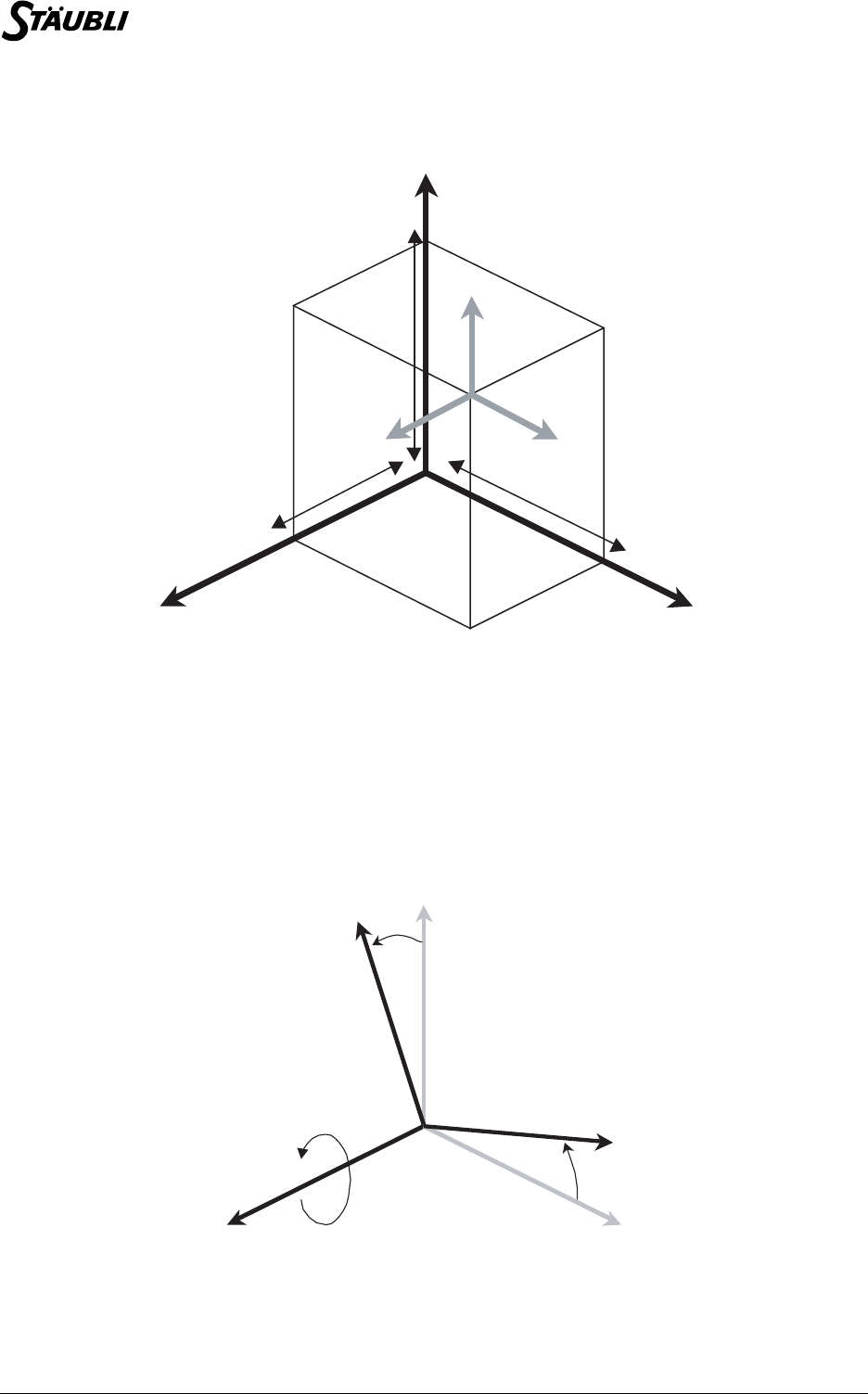
98 / 160 D28062804A - 02/2006
8.3.2. ORIENTATION
Orientation
The position of frame R2 (grey) relative to R1 (black) is:
x = 250mm, y = 350 mm, z = 450mm, rx = 0°, ry = 0°, rz = 0°
Coordinates rx, ry and rz correspond to the angles of rotation that must be applied successively about the
x, y and z axis to obtain the orientation of the frame.
For example, orientation rx = 20°, ry = 10°, rz = 30° is obtained as follows. First, the frame (x,y,z) is
rotated through 20° about the x axis. This gives a new frame (x’,y’,z’). The x and x’ axis coincide.
Frame rotation about the axis: X
Then the frame is rotated through 20° about the y’ axis of the frame obtained at the previous step. This
gives a new frame (x’’,y’’,z’’). The y’ and y’’ axis coincide.
x1 y1
z1
250 mm
350 mm
450 mm
x2 y2
z2
y
z
20°
y’
z’
x = x’
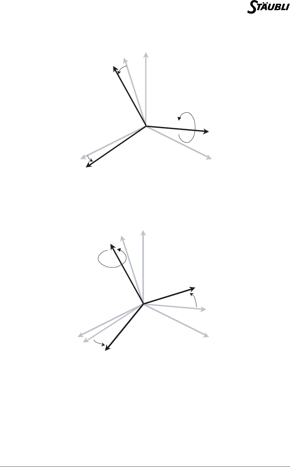
Chapter 8 - Arm positions
D28062804A - 02/2006 99 / 160
Frame rotation about the axis: Y’
Lastly, the frame is rotated through 20° about the z’’ axis of the frame obtained at the previous step. The
orientation of the new frame obtained (x’’’,y’’’,z’’’) is defined by rx, ry, rz. The z’’ and z‘’’ axis coincide.
Frame rotation about the axis: Z’’
The position of frame R2 (grey) relative to R1 (black) is:
x = 250mm, y = 350 mm, z = 450mm, rx = 20°, ry = 10°, rz = 30°
The values of rx, ry and rz are defined modulo 360 degrees. When the system calculates rx, ry and rz,
their values are always between -180 and +180 degrees. Several possible values of rx, ry, and rz still
remain: The system ensures that at least two coordinates are between -90 and 90 degrees (unless rx is
+180 and ry 0). When ry is 90 degrees (modulo 180), the selected value of rx is zero.
x = x’ y
z
10°
y’ = y’’
z’
z’’
x’’
x = x’ y
z
30°
y’ = y’’
z’
z’’
x’’
x’’’
y’’’

100 / 160 D28062804A - 02/2006
8.3.3. OPERATORS
In ascending order of priority:
8.3.4. INSTRUCTIONS
num distance(trsf position1, trsf position2)
Syntax
num distance(<trsf position1>, <trsf position2>)
Function
Returns the distance between position1 and position2.
Parameter
Example
// Displays the distance between two points, whatever their reference frames
putln(distance(position(point1, world), position(point2, world)))
See also
point appro(point position, trsf transformation)
point compose(point position, frame reference, trsf transformation)
trsf position(point position, frame reference)
num distance(point position1, point position2)
trsf <trsf& position1> = <trsf position2> Assigns position2 to the position1 variable field by
field and returns position2.
bool <trsf position1> != <trsf position2> Returns true if a position1 field is not equal to the
corresponding position2 field, otherwise it returns
false.
bool <trsf position1> == <trsf position2> Returns true if each position1 field is equal to the
corresponding position2 field, otherwise it returns
false.
trsf <trsf position1> <trsf position2> Returns the geometrical composition of the
position1 and position2 transformations. Caution!
Usually, ! position1 position2 ! = position2
position1!
trsf ! <trsf position> Returns the inverse transformation of position.
CAUTION:
To ensure that the distance is valid, position 1 and position 2 must be defined relative to
the same reference frame.
trsf position1 Transformation type expression
trsf position2 Transformation type expression
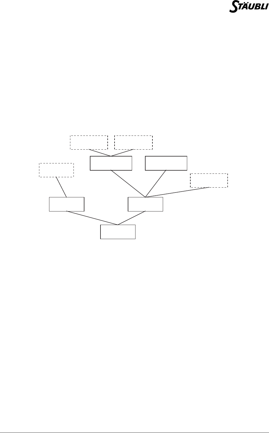
Chapter 8 - Arm positions
D28062804A - 02/2006 101 / 160
8.4. FRAME TYPE
8.4.1. DEFINITION
The frame type is used to define the position of reference frames in the cell.
The frame type is a structured type with only one accessible field:
The reference frame of a frame type variable is defined when it is initialized (via the user interface, or via
the = operator). The frame type world reference frame is always defined in a VAL3 application: a
reference frame is linked to the world frame, either directly or via other frames.
An execution error is generated during a geometrical calculation if the world frame coordinates have been
modified.
Links between reference frames
By default, a frame type variable uses world as its reference frame.
8.4.2. USE
The use of reference frames in a robotic application is highly recommended for the following purposes:
trsf trsf position of the frame in its reference frame
-To give a more intuitive view of the application points
The cell taught point display is structured according to the hierarchical structure of the frames.
-To update the position of a set of points quickly
When an application point is linked to an object, it is advisable to define a frame for that object and
link the VAL3 points to the frame. If the object is moved, simply reteach the frame to allow all linked
points to be corrected at the same time.
-To reproduce a trajectory in several places in the cell
Define the trajectory points relative to a working frame and teach a frame for each position in which
the trajectory is to be reproduced. By assigning the value of a taught frame to the working frame, the
entire trajectory "moves" to the taught frame.
-To make it easier to calculate geometrical movements
The compose() instruction allows geometrical movements expressed in any reference frame to be
performed on any point. The position() instruction is used to calculate the position of a point in any
reference frame.
world
frame1 frame2
frame 21 frame 21
point1a
point21a point21b
point2a

102 / 160 D28062804A - 02/2006
8.4.3. OPERATORS
In ascending order of priority:
8.4.4. INSTRUCTIONS
num setFrame(point origin, point axisOx, point planeOxy, frame&
reference)
Syntax
num setFrame(point origin, point axisOx, point planeOxy, frame& reference)
Function
Calculates the coordinates of reference from its origin, from an axisOx point on the axis (Ox), and a
planeOxy point on the plane (Oxy).
The axisOx point must be on the side of the positive x values. The planeOxy point must be on the side of
the positive y values.
The function returns:
An execution error is generated if one of the points has no reference frame.
8.5. TOOL TYPE
8.5.1. DEFINITION
The tool type is used to define the geometry and action of a tool.
The tool type is a stuctured type with the following fields, in this order:
The basic tool of a tool type variable is defined when it is initialized (via the user interface, or via the =
operator). The flange basic tool, of tool type, is always defined in a VAL3 application: all tools are linked
to the flange tool, either directly or via other tools.
An execution error is generated during a geometrical computation if the flange tool coordinates have been
modified.
frame <frame& reference1> = <frame
reference2>
Assigns the position and the reference frame of
reference2 to the reference1 variable.
bool <frame reference1> != <frame
reference2>
Returns true if reference1 and reference2 do not
have the same reference frame or the same position
in their reference frame.
bool <frame reference1> == <frame
reference2>
Returns true if reference1 and reference2 have the
same position in the same reference frame.
0No error.
-1 The axisOx point is too close to the origin.
-2 The planeOxy point is too close to the axis (Ox).
trsf trsf position of the tool center point (TCP) in its basic tool
dio gripper Output used to activate the tool
num otime Time required to open the tool (seconds)
num ctime Time required to close the tool (seconds)
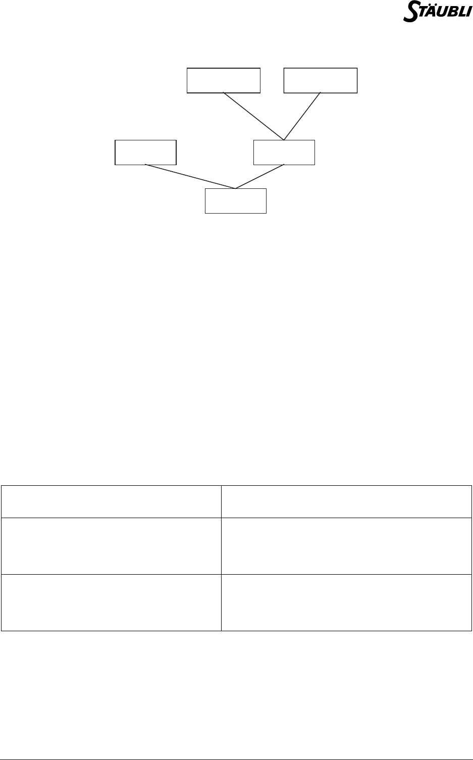
Chapter 8 - Arm positions
D28062804A - 02/2006 103 / 160
Links between tools
By default, the output of a tool is the system io:valve1 output, the opening and closing times are 0 and the
basic tool is flange.
8.5.2. USE
The use of tools in a robotic application is highly recommended for the following purposes:
8.5.3. OPERATORS
In ascending order of priority:
-To control the speed of movement
During manual or programmed movements, the system controls the Cartesian speed at the end of the
tool.
-To reach the same points with different tools
Simply select the VAL3 tool corresponding to the physical tool at the end of the arm.
-To control tool wear or a tool change
To update the arm position, simply update the geometrical coordinates of the tool.
tool <tool& tool1> = <tool tool2> Assigns the position and the basic tool of tool2 to
the tool1 variable.
bool <tool tool1> != <tool tool2> Returns true if tool1 and tool2 do not have the
same basic tool, the same position in their basic tool,
the same digital output or the same opening and
closing times.
bool <tool tool1> == <tool tool2> Returns true if tool1 and tool2 have the same
position in the same basic tool, and use the same
digital output with the same opening and closing
times.
flange
tool 21 tool 22
tool 2tool 1

104 / 160 D28062804A - 02/2006
8.5.4. INSTRUCTIONS
void open(tool tool)
Syntax
void open (tool tool)
Function
Activates the tool (opening) by setting its digital output to true.
Before activating the tool, open() waits for the robot to reach the required point by carrying out the
equivalent of a waitEndMove(). After activation, the system waits for otime seconds before executing the
next instruction.
This instruction does not make sure that the robot is stabilized in its final position before the tool is
activated. When it is necessary to wait for complete stabilization of the movement, the isSettled()
instruction must be used.
An execution error is generated if the tool dio is not defined or is not an output, or if a previously recorded
motion command cannot be run.
Parameter
Example
// the open() instruction is equivalent to:
waitEndMove()
tTool.gripper=true
delay(tTool.otime)
See also
void close(tool tool)
void waitEndMove()
void close(tool tool)
Syntax
void close (tool tool)
Function
Activates the tool (closing) by setting its digital output to false.
Before activating the tool, open() waits for the robot to stop at the point by carrying out the equivalent of a
waitEndMove(). After activation, the system waits for ctime seconds before executing the next instruction.
This instruction does not make sure that the robot is stabilized in its final position before the tool is
activated. When it is necessary to wait for complete stabilization of the movement, the isSettled()
instruction must be used.
An execution error is generated if the tool dio is not defined or is not an output, or if a previously recorded
motion command cannot be run.
Parameter
Example
// the close instruction is equivalent to:
waitEndMove()
tTool.gripper = false
delay(tTool.ctime)
tool tool Tool type expression
tool tool Tool type expression
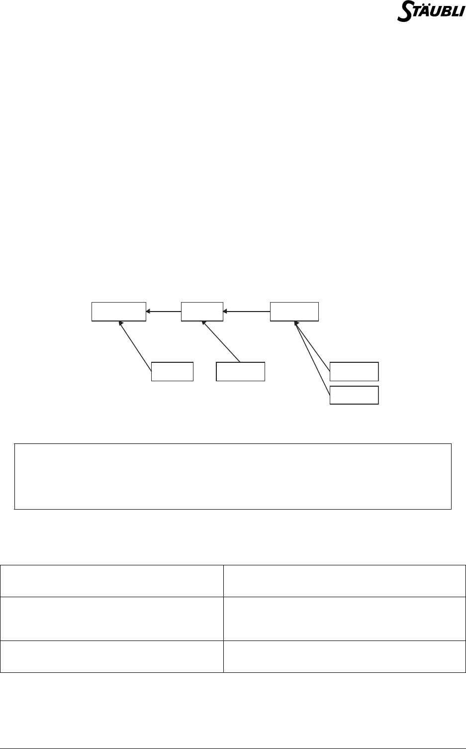
Chapter 8 - Arm positions
D28062804A - 02/2006 105 / 160
See also
Type tool
void open(tool tool)
void waitEndMove()
8.6. POINT TYPE
8.6.1. DEFINITION
The point type is used to define the position and orientation of the robot tool in the cell.
The point type is a stuctured type with the following fields, in this order:
The reference frame of a point is a frame type variable defined when it is initialized (via the user interface,
using the = operator and the here(), appro() and compose() instructions.
Point definition
An execution error is generated if a point type variable with no defined reference frame is used.
8.6.2. OPERATORS
In ascending order of priority:
trsf trsf position of the point in its reference frame
config config arm configuration used to reach the position
CAUTION:
By default, a local point type variable has no reference frame. Before it can be used, it
must be initialized from another point, or via one of the here(), appro() and compose()
instructions.
point <point& point1> = <point point2> Assigns the position, the configuration and the
reference frame of point2 to the point1 variable.
bool <point point1> ! = <point point2> Returns true if point1 and point2 do not have
the same reference frame or the same position
in their reference frame.
bool <point point1> == <point point2> Returns true if point1 and point2 have the same
position in the same reference frame.
Frame world Fr ame f1
Point p0
Frame f2
Point p 2 Point p1
Point p 3

106 / 160 D28062804A - 02/2006
8.6.3. INSTRUCTIONS
num distance(point position1, point position2)
Syntax
num distance(point position1, point position2)
Function
Returns the distance between position1 and position2.
An execution error is generated if position1 or position2 do not have a defined reference frame.
Parameter
Example
// Displays the distance between two points, whatever their reference frames
putln(distance(point1, point2))
See also
point appro(point position, trsf transformation)
point compose(point position, frame reference, trsf transformation)
trsf position(point position, frame reference)
num distance(trsf position1, trsf position2)
point position1 Point type expression
point position2 Point type expression

Chapter 8 - Arm positions
D28062804A - 02/2006 107 / 160
point compose(point position, frame reference, trsf transformation)
Syntax
point compose(point position, frame reference, trsf transformation)
Function
Returns the position to which the geometrical transformation transformation is applied relative to
reference frame.
The reference frame and the configuration of the point returned are those of position.
An execution error is generated if position has no defined reference frame.
Parameter
Example
point pResult
// modification of the orientation without modification of position
pResult = compose (position,reference,transformation)
pResult.trsf.x = position.trsf.x
pResult.trsf.y = position.trsf.y
pResult.trsf.z = position.trsf.z
// modification of position without modification of the orientation
transformation.rx = transformation.ry =transformation.rz = 0
pResult = compose (pResult,reference,transformation)
See also
Operator trsf <trsf position1> * <trsf position2>
point appro(point position, trsf transformation)
CAUTION:
The rotation component of transformation usually modifies not only the orientation of
position, but also its Cartesian coordinates (unless position is located at the origin of
reference frame).
If we only want transformation to modify the orientation of position, it is necessary to
update the result using the Cartesian coordinates of position (see example).
point position Point type expression
frame reference Reference frame type expression
trsf transformation Transformation type expression

108 / 160 D28062804A - 02/2006
point appro(point position, trsf transformation)
Syntax
point appro(point position, trsf transformation)
Function
Returns a point computed by a geometric transformation of an input position. The transformation
coordinates are given in the same base as the input position (the base of the input position's reference
frame).
The reference frame and the configuration of the returned point are those of the input position.
An execution error is generated if position has no defined reference frame.
Parameter
Example
See also
Operator trsf <trsf position1> * <trsf position2>
point compose(point position, frame reference, trsf transformation)
point here(tool tTool, frame fFrame)
Syntax
point here(tool tool, frame reference)
Function
Returns the current position of the tool tool in reference frame(the position commanded and not the
position measured).
The reference frame of the point returned is reference. The configuration of the point returned is the
current configuration of the arm.
See also
joint herej()
config config(joint position)
point jointToPoint(tool tool, frame reference, joint position)
point position Point type expression
trsf transformation Transformation type expression
// move to 100 mm above the point (Z axis)
point p
movej(appro(p,{0,0,-100,0,0,0}), flange, mNomDesc) // Approach
movel(p, flange, mNomDesc) // Go to point

Chapter 8 - Arm positions
D28062804A - 02/2006 109 / 160
point jointToPoint(tool tool, frame reference, joint position)
Syntax
point jointToPoint (tool tool, frame reference, joint position)
Function
Returns the position of the tool in the reference frame when the arm is in the revolute position position.
The reference frame of the point returned is reference. The configuration of the point returned is the
configuration of the arm in the revolute position position.
Parameter
See also
point here(tool tTool, frame fFrame)
bool pointToJoint(tool tool, joint initial, point position,joint& coordinates)
bool pointToJoint(tool tool, joint initial, point position,joint&
coordinates)
Syntax
bool pointToJoint(tool tool, joint initial, point position, joint& coordinates)
Function
Calculates the revolute coordinates corresponding to the specified position. Returns true if revolute
coordinates have been found, and returns false if no solution has been found.
The revolute position to be located corresponds to the configuration of the position. Fields with the value
free do not determine the configuration. Fields with the value same specify the same configuration as
initial.
For axis that can rotate through more than one full turn, there are several revolute solutions with exactly
the same configuration: the solution closest to initial is then taken.
No solution is possible if position is out of reach (arm too short) or outside the software limits. If position
specifies a configuration, it may be outside the limits for that configuration, but within the limits for a
different configuration.
An execution error is generated if position has no defined reference frame.
Parameter
See also
joint herej()
point jointToPoint(tool tool, frame reference, joint position)
tool tool Tool type expression
frame reference Reference frame type expression
joint position Revolute position type position
tool tool Tool type expression
joint initial Revolute position type position
point position Point type expression
joint& coordinates Revolute position type variable

110 / 160 D28062804A - 02/2006
trsf position(point position, frame reference)
Syntax
trsf position(point position, frame reference)
Function
Returns the coordinates of position in reference frame.
An execution error is generated if position has no reference frame.
Example
// Displays the distance between two points, whatever their reference frames
putln(distance(position(point1, world), position(point2, world)))
See also
num distance(point position1, point position2)

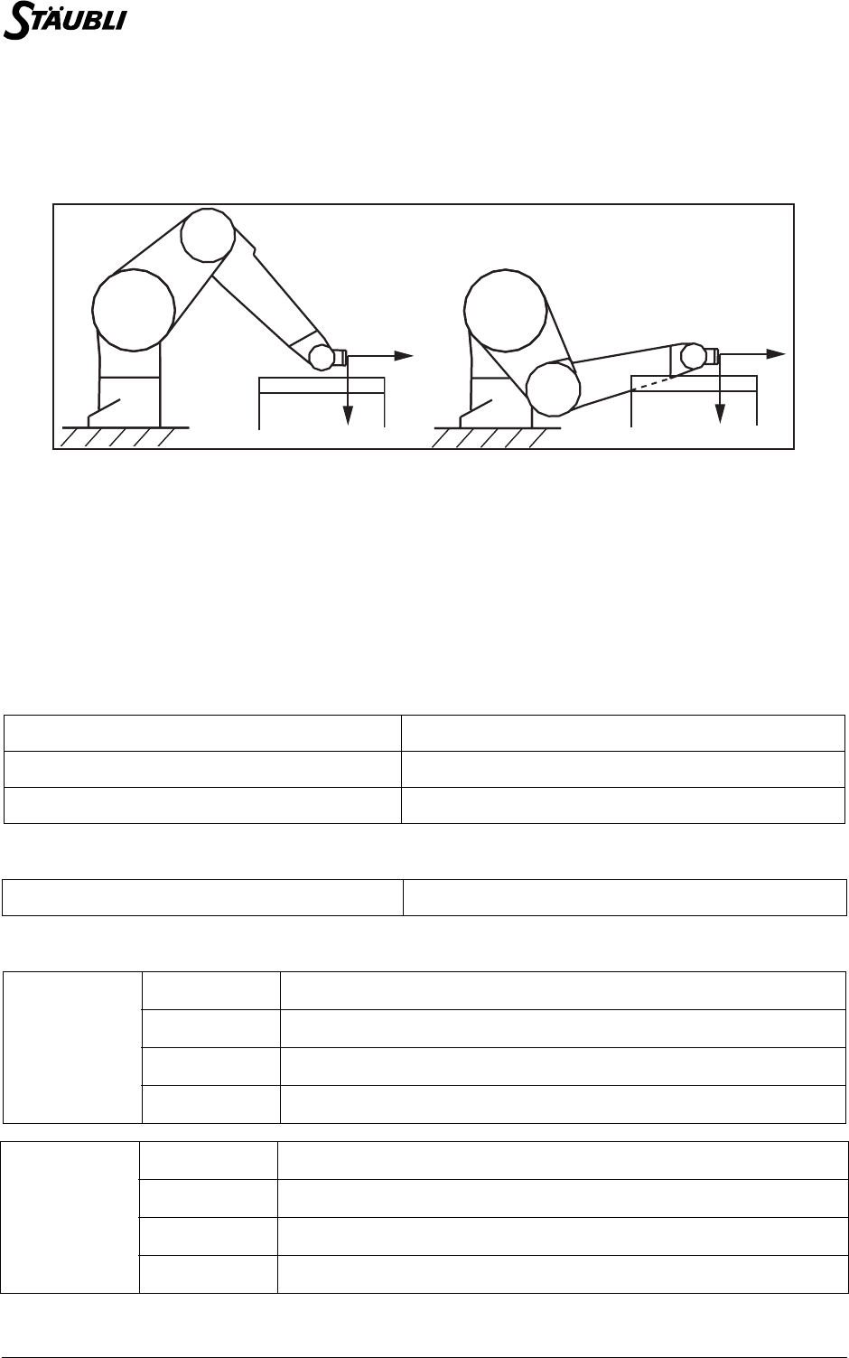
112 / 160 D28062804A - 02/2006
8.7.1. INTRODUCTION
There are generally several ways in which a robot can reach a given Cartesian point.
These possibilities are known as "configurations". The figure below illustrates two different configurations:
Two configurations that can be used to reach a given point: P
In some cases, among all the possible configurations, it is important to specify the ones that are valid and
the ones that are to be prohibited. To deal with this problem, the point type is used to specify the
configurations allowed for the robot, via its config type field as defined below.
8.7.2. DEFINITION
The config type is used to define the configurations authorized for a given Cartesian position.
It depends on the type of arm used.
For a Stäubli RX/TX arm, the config type is a structured type whose fields are, in that order:
For a Stäubli RS arm, the config type is limited to the Shoulder field:
The shoulder, elbow and wrist fields can have the following values:
shoulder shoulder configuration
elbow elbow configuration
wrist wrist configuration
shoulder shoulder configuration
shoulder
righty righty shoulder configuration imposed
lefty lefty shoulder configuration imposed
ssame Shoulder configuration change not allowed
sfree Free shoulder configuration
elbow
epositive epositive elbow configuration imposed
enegative enegative elbow configuration imposed
esame Elbow configuration change not allowed
efree Free elbow configuration
PP
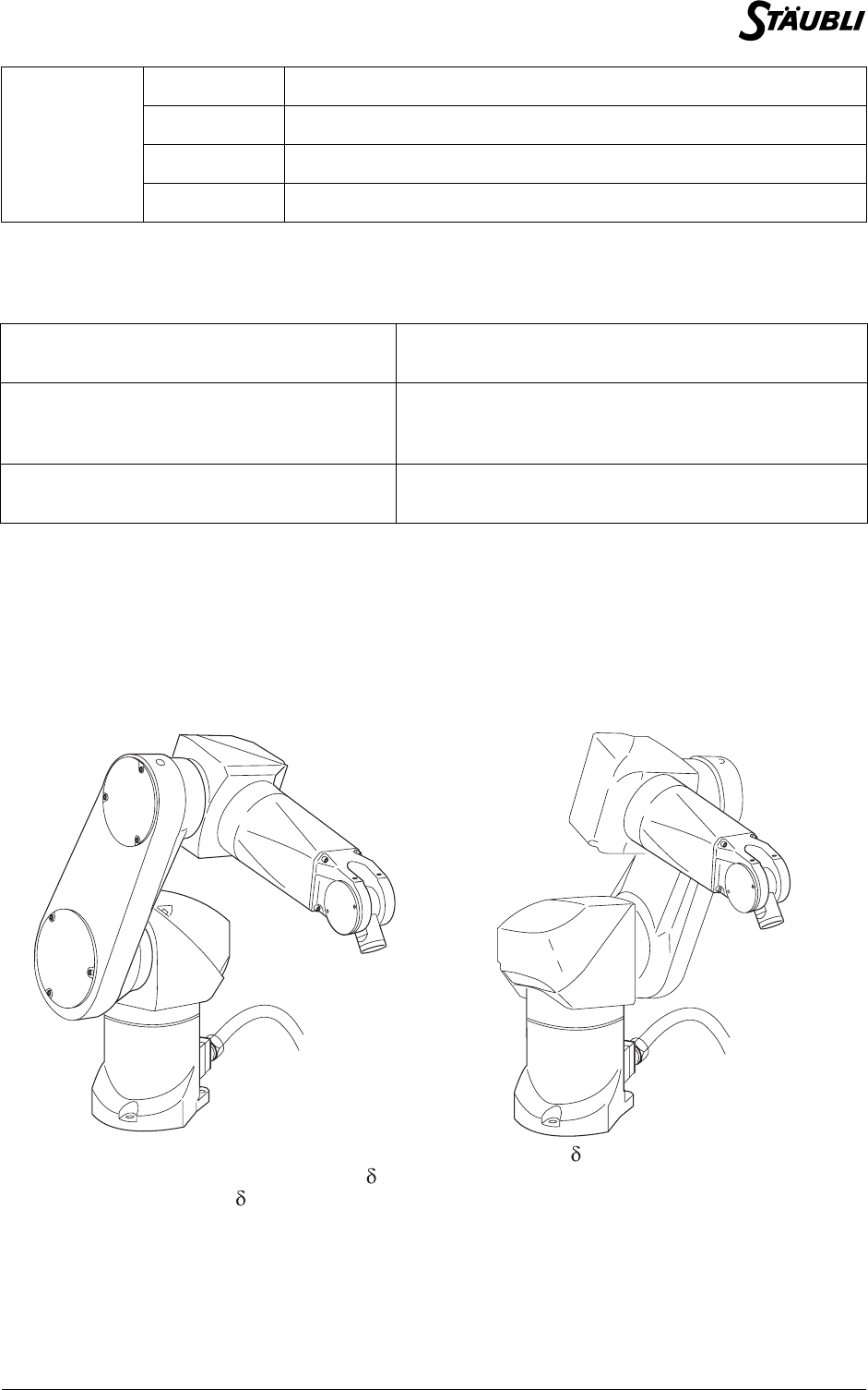
Chapter 8 - Arm positions
D28062804A - 02/2006 113 / 160
8.7.3. OPERATORS
In ascending order of priority:
8.7.4. CONFIGURATION (RX/TX ARM)
8.7.4.1. SHOULDER CONFIGURATION
To reach a given Cartesian point, the arm of the robot may be to the right or the left of the point: these two
configurations are called righty and lefty.
The righty configuration is defined by (d1.sin(j2) + d2.sin(j2+j3) + ) < 0, and the lefty configuration
is defined by (d1.sin(j2) + d2.sin(j2+j3) + ) >= 0, where d1 is the length of the robot arm, d2 the
length of the forearm, and the distance between axis 1 and axis 2, in the x direction.
wrist
wpositive wpositive wrist configuration imposed
wnegative wnegative wrist configuration imposed
wsame Wrist configuration change not allowed
wfree Free wrist configuration
config <config& configuration1> =
<config configuration2>
Assigns the shoulder, elbow and wrist fields for
configuration2 to the configuration1 variable.
bool <config configuration1> != <config
configuration2>
Returns true if configuration1 and configuration2
do not have the same shoulder, elbow or wrist field
values.
bool <config configuration1> == <config
configuration2>
Returns true if configuration1 and configuration2
have the same shoulder, elbow or wrist field values.
Configuration: righty Configuration: lefty
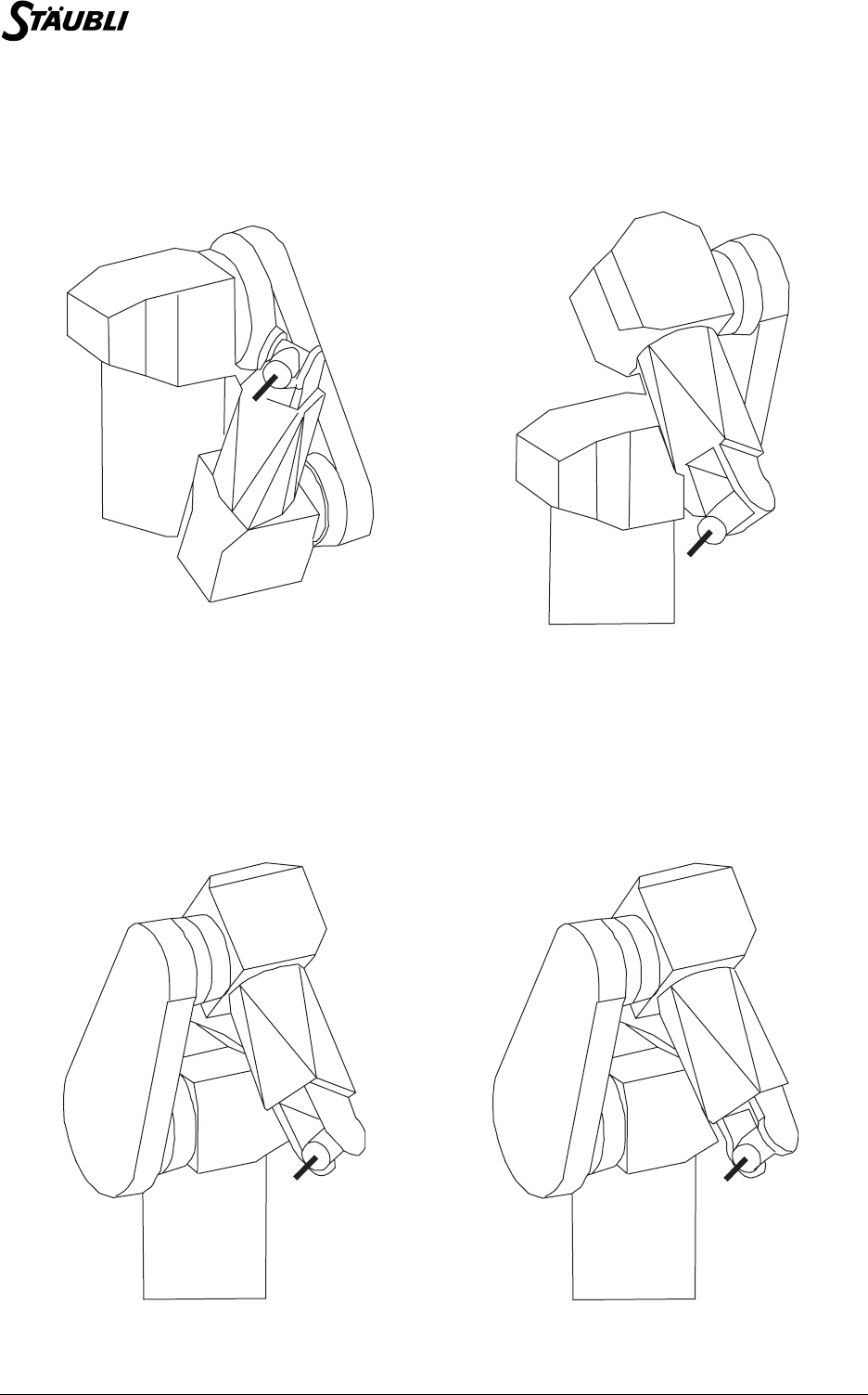
114 / 160 D28062804A - 02/2006
8.7.4.2. ELBOW CONFIGURATION
In addition to the shoulder configuration, there are two robot elbow configurations: the elbow
configurations are called epositive and enegative.
The epositive configuration is defined by j3 >= 0.
The enegative configuration is defined by j3 < 0.
8.7.4.3. WRIST CONFIGURATION
In addition to the shoulder and elbow configurations, there are two robot wrist configurations. The two wrist
configurations are called wpositive and wnegative.
The wpositive configuration is defined by q5 >= 0.
The wnegative configuration is defined by q5 < 0.
Configuration: enegative Configuration: epositive
Configuration: wnegative Configuration: wpositive
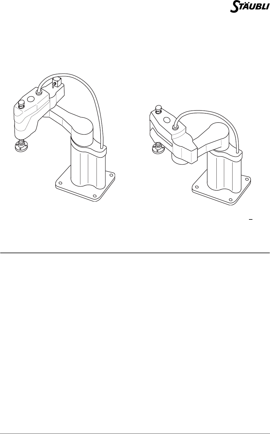
Chapter 8 - Arm positions
D28062804A - 02/2006 115 / 160
8.7.5. CONFIGURATION (RS ARM)
To reach a given Cartesian point, the arm of the robot may be to the right or the left of the point: these two
configurations are called righty and lefty.
The righty configuration is defined by sin(j2) > 0, and the lefty configuration is defined by sin(j2) < 0.
8.7.6. INSTRUCTIONS
config config(joint position)
Syntax
config config(joint position)
Function
Returns the configuration of the robot for the revolute position position.
Parameter
See also
point here(tool tTool, frame fFrame)
joint herej()
Configuration: righty Configuration: lefty
joint position Revolute position type position


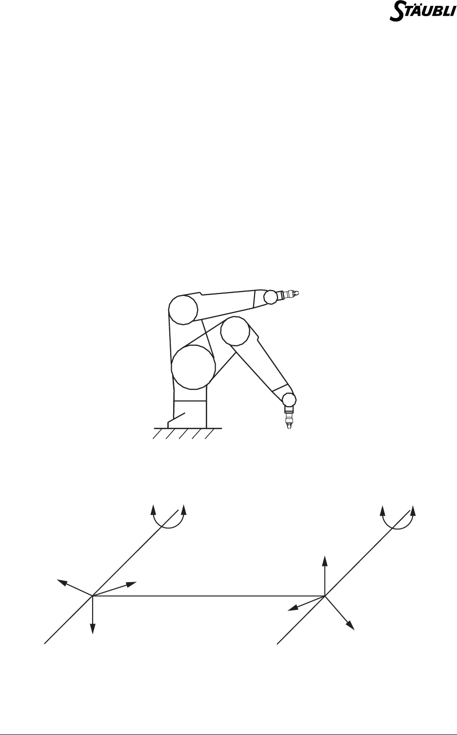
Chapter 9 - Movement control
D28062804A - 02/2006 119 / 160
9.1. TRAJECTORY CONTROL
A succession of points is not sufficient to define the trajectory of a robot. It is also necessary to indicate the
type of trajectory used between the points (curve or straight line), specify how the trajectories are linked
together and define the movement speed parameters. This section therefore presents the point-to-point
movements and straight line movements (movej and movel instructions) and describes how to use the
movement descriptor parameters (mdesc type).
9.1.1. TYPES OF MOVEMENT: POINT-TO-POINT, STRAIGHT LINE, CIRCLE
The robot's movements are mainly programmed using the movej, movel and movec instructions. The
movej instruction can be used to make point-to-point movements, movel is used for straight line
movements, and movec for circular movements.
A point-to-point movement is a movement in which only the final destination (Cartesian or revolute point) is
important. Between the start point and the end point, the tool center point follows a curve defined by the
system to optimize the speed of the movement.
Initial and final positions
Conversely, in the case of a straight line movement, the tool center point moves along a straight line. The
orientation is interpolated in a linear way between the initial and final orientation of the tool.
Straight line movement
Initial position
Final position
ZY
X
Z
Y
X
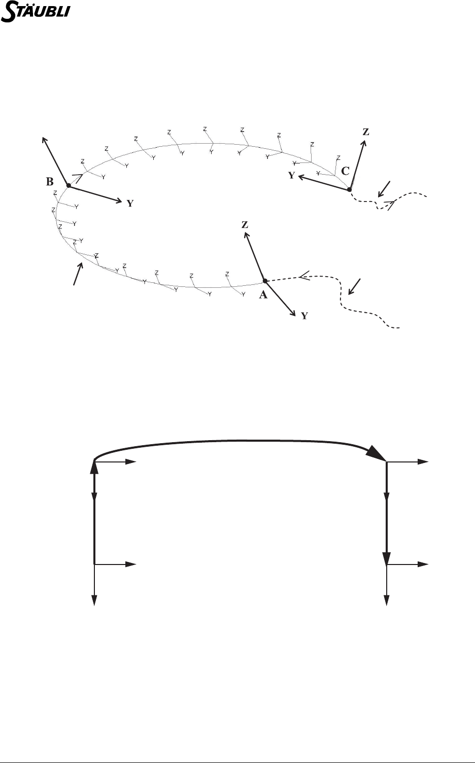
120 / 160 D28062804A - 02/2006
In a circular movement, the tool center point moves through an arc defined by 3 points, and the tool
orientation is interpolated between the initial orientation, the intermediate orientation, and the final
orientation.
Circular movement
Example:
A typical handling task involves picking up parts at one location and putting them down at another. Let us
assume that the parts are to be picked up at the PICK point and put down at the PLACE point. To go from
the PICK point to the PLACE point, the robot must pass through a disengagement point DEPART and an
approach point APPRO.
Cycle type: U
Let us assume that the robot is initially at the PICK point. The program required to execute the movement
can be written as follows:
movel(DEPART, tool, mDesc)
movej(APPRO, tool, mDesc)
movel(PLACE, tool, mDesc)
Z
Trajectory followed by the tool
during circular movement
Previous movement
Next movemen
t
DEPART
PICK
APPRO
PLACE
Z
Z
Z
Z
X
XX
X
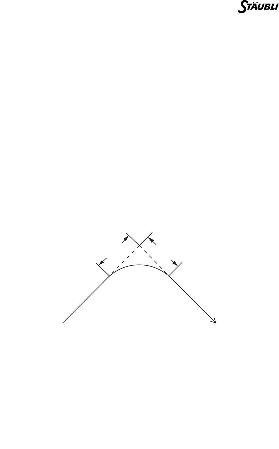
Chapter 9 - Movement control
D28062804A - 02/2006 121 / 160
Straight line movements are used for disengagement and approach. However, the main movement is a
point-to-point movement, as the geometry of this part of the trajectory does not need to be accurately
controlled, because the aim is to move as quickly as possible.
Note:
The geometry of the trajectory does not depend on the speed at which both these types of
movement are executed. The robot always passes through the same position. This is
particularly important when developing applications. It is possible to start with slow
movements and then progressively increase the speed without distorting the trajectory of
the robot.
9.1.2. MOVEMENT SEQUENCING
9.1.2.1. BLENDING
Let us now return to the example of the U cycle described in the previous chapter. In the absence of any
specific movement sequencing control, the robot stops at the DEPART and APPRO points, as the
trajectory is angled at these points. This unnecessarily increases the duration of the operation and there is
no need to pass through these precise points.
The duration of the movement can be significantly reduced by "blending" the trajectory in the vicinity of the
DEPART and APPRO points. To do so, we use the blend field of the movement descriptor. When this field
is set to off, the robot stops at each point along the trajectory. However, when the parameter is set to joint,
the trajectory is blended in the vicinity of each point and the robot no longer stops at the fly-by points.
When the blend field has the value joint, two other parameters must be specified: leave and reach.
These parameters determine the distance from the arrival point at which the nominal trajectory is left (start
of blending) and the distance from the arrival point at which it is rejoined (end of blending).
Definition of the distances: ’leave’ / ’reach’
Example:
Let us return to the program described in the section entitled "Types of movement: point-to-point or straight
line". The previous movement program can be modified as follows:
mDesc.blend = joint
mDesc.leave = 50
mDesc.reach = 200
movel(DEPART, tool, mDesc)
mDesc.leave = 200
mDesc.reach = 50
movej(APPRO, tool, mDesc)
mDesc.blend = OFF
movel(PLACE, tool, mDesc)
LEAVE
REACH
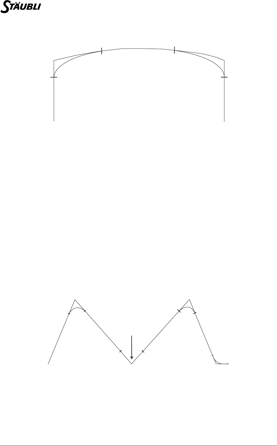
122 / 160 D28062804A - 02/2006
The following trajectory is obtained:
Blended cycle
The robot no longer stops at the DEPART and APPRO points. The movement is therefore faster. In fact,
the larger the leave and reach distances, the faster the movement.
9.1.2.2. CANCEL BLENDING
The waitEndMove() instruction is used to cancel the effect of blending. The robot then completes the last
programmed movement as far as its arrival point, as if the movement descriptor blend field were set to off.
For example, let us examine the following program:
mDesc.blend = joint
mDesc.leave = 10
mDesc.reach = 10
movej(A, tool, mDesc)
movej(B, tool, mDesc)
waitEndMove()
movej(C, tool, mDesc)
movej(D, tool, mDesc)
etc.
The trajectory followed by the robot is then as follows:
Cycle without blending at a given point
200
50
200
50
DEPART
PICK
APPRO
PLACE
A
B
C
D
10
10
10
10
10
10
10
10
No smoothing at B
(BREAK)

Chapter 9 - Movement control
D28062804A - 02/2006 123 / 160
9.1.3. MOVEMENT RESUMPTION
When the arm power is cut off before the robot has finished its movement, following an emergency stop for
example, movement resumption is required when power is restored to the system. If the arm has been
moved manually during the stoppage, it may be in a position far from its normal trajectory. It is then
necessary for movement resumption to take place without a collision occurring. The CS8's trajectory
control function provides the possibility of managing movement resumption using a "connection
movement".
When movement resumes, the system ensures that the robot is indeed on its programmed trajectory: if
there is any deviation, however slight, it automatically stores a point-to-point command to reach the exact
position at which the robot left its trajectory: it is a "connection movement". This movement is made at low
speed. It must be validated by the operator, except in automatic mode, in which it can be carried out
without human intervention. The autoConnectMove() instruction is used to detail behaviour in automatic
mode.
The resetMotion() instruction is used to cancel the current movement, and possibly to program a
connection movement in order to resume a position at low speed and under the operator's control.
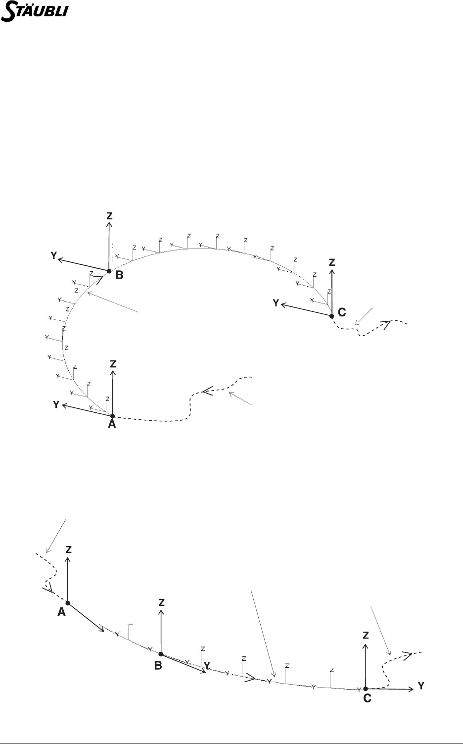
124 / 160 D28062804A - 02/2006
9.1.4. PARTICULARITIES OF CARTESIAN MOVEMENTS (STRAIGHT LINE,
CIRCLE)
9.1.4.1. INTERPOLATION OF THE ORIENTATION
The trajectory generator of the CS8 always minimizes the amplitude of tool rotations when moving from
one orientation to another.
This makes it possible, as a particular case, to program a constant orientation, in absolute terms, or as
compared with the trajectory, on all straight-line or circular movements.
•For a constant orientation, the initial and final positions, and the intermediate position for a circle,
must have the same orientation.
Constant orientation in absolute terms
•For a constant orientation as compared with the trajectory (e.g. direction Y for the tool marker tangent
to the trajectory), the inital and final positions, and the intermediate position for a circle, must have the
same orientation as compared with the trajectory.
Constant orientation as compared with the trajectory
Previous movement
Next movemen
t
Trajectory followed by the tool
during circular movement
(Orientation stays the same)
Y
Trajectory followed by the tool
during circular movement
(Orientamento tangente)
Previous movement
Next movement
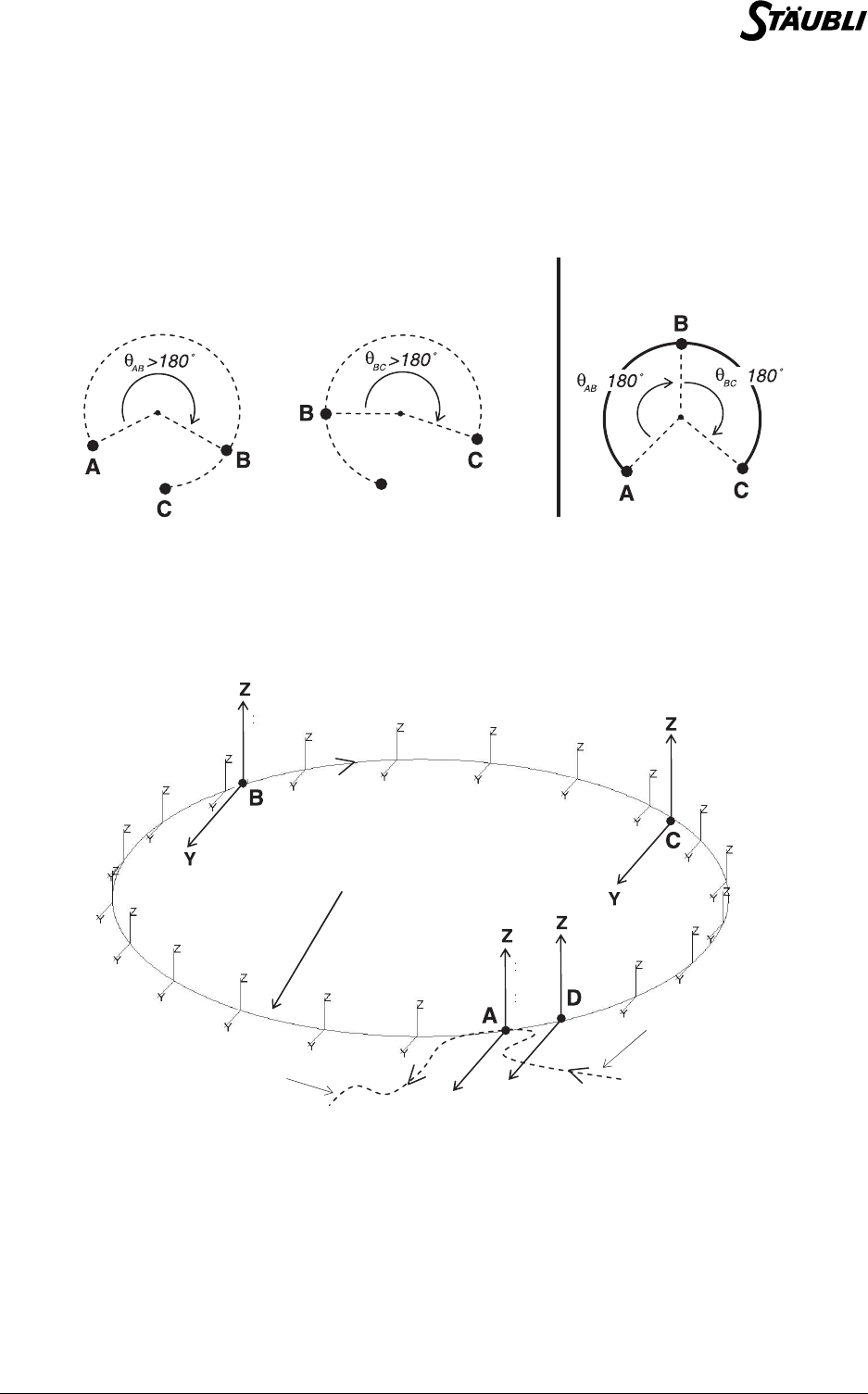
Chapter 9 - Movement control
D28062804A - 02/2006 125 / 160
This results in a limitation for circular movements:
If the intermediate point forms an angle of 180° or more with the initial point or the final point, there are
several interpolation solutions for the orientation, and an error is generated.
It is then necessary to modify the position of the intermediate point to remove the ambiguity from the
intermediate orientations.
Ambiguity as to the intermediate orientation
In particular, programming a full circle involves 2 movec instructions:
movec (B, C, tool, mDesc)
movec (D, A, tool, mDesc)
Full circle
OK !
A
• •
Error: circular movements
Y
Previous
movement
Next
movement
Trajectory followed by the tool
during circular movement
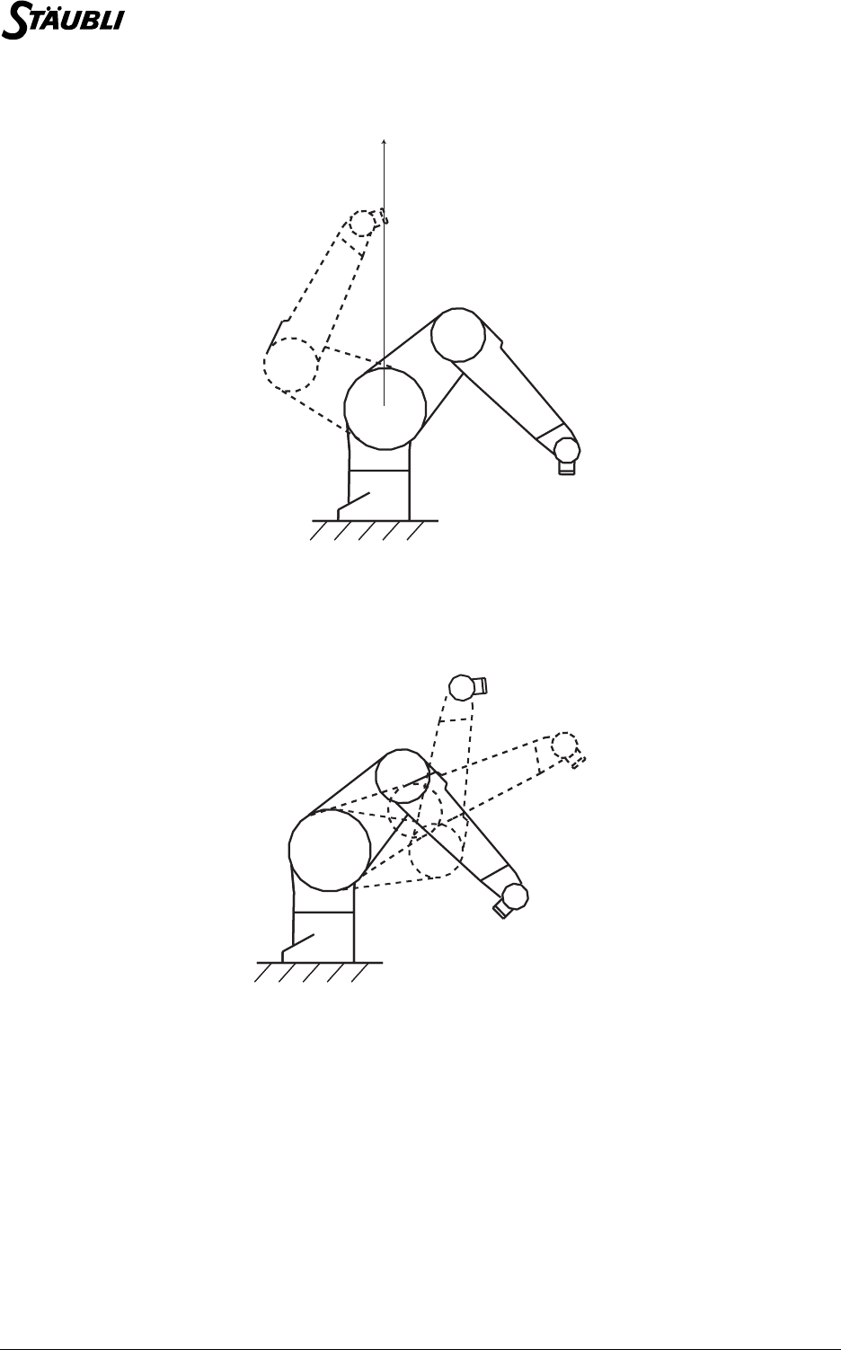
126 / 160 D28062804A - 02/2006
9.1.4.2. CONFIGURATION CHANGE (ARM RX/TX)
Configuration change: righty / lefty
During a change of shoulder configuration, the centre of the robot's wrist has to pass vertically through axis
1 (but not exactly in the case of offset robots).
Positive/negative elbow configuration change
During a change of elbow configuration, the arm has to go through the straight arm position (q3 = 0°).
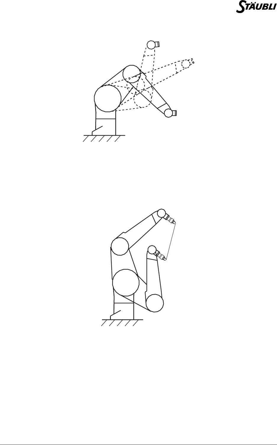
Chapter 9 - Movement control
D28062804A - 02/2006 127 / 160
Positive/negative wrist configuration change
During a change of wrist configuration, the arm has to go through the straight wrist position (q5 = 0°).
The robot must therefore pass through specific positions during a configuration change. But we cannot
require a straight-line or circular movement to pass through these positions if they are not on the desired
trajectory! This means that we cannot impose a change of configuration during a straight-line or
circular movement.
Elbow configuration change impossible
In other words, during a straight-line or circular movement, we can only impose a configuration if it is
compatible with the initial position: it is therefore always possible to specify a free configuration, or one that
is identical to the initial configuration.
In certain exceptional cases, the straight line or arc does indeed pass through a position in which a change
of configuration is possible. In this case,if the configuration has been left free, the system can decide to
change the configuration during a straight-line or circular movement.
For a circular movement, the configuration of the intermediate point is not taken into account. The only
configurations that count are those of the initial and final positions.
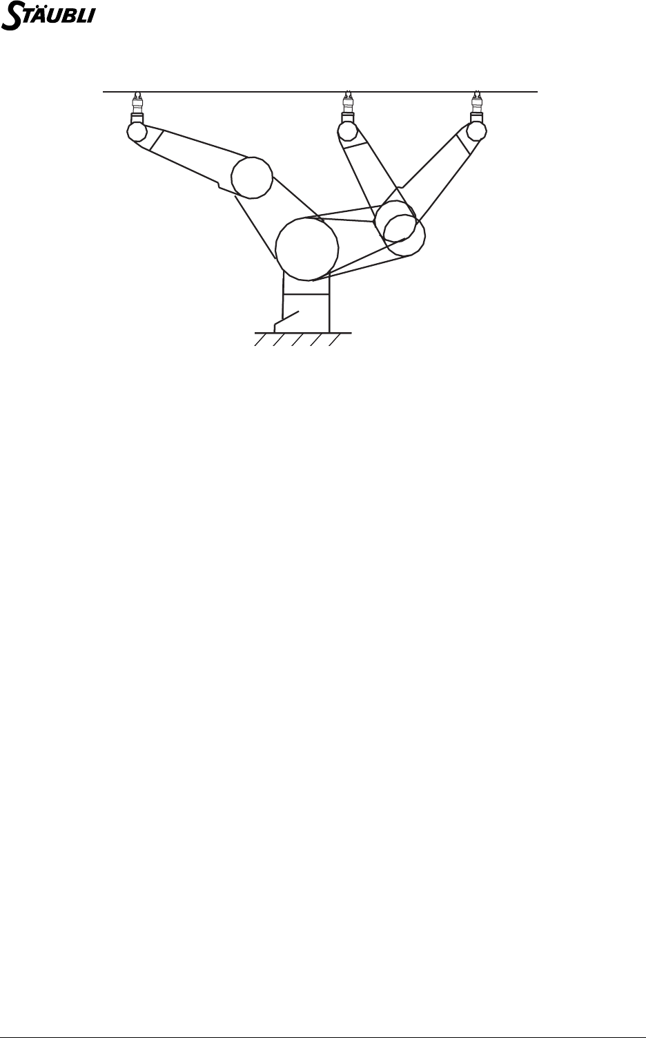
128 / 160 D28062804A - 02/2006
Shoulder configuration change possible
9.1.4.3. SINGULARITIES (ARM RX/TX)
Singularities are an inherent characteristic of all 6-axis robots. Singularities can be defined as the points at
which the robot changes configuration. Certain axis are then aligned: two aligned axes behave as a single
axis and the 6-axis therefore behaves locally as a 5-axis robot. The end effector is then unable to carry out
certain movements. This is not a problem in the case of a point-to-point movement: system-generated
movements are still possible. On the other hand, during a straight-line or circular movement, we impose a
movement geometry. If the movement is impossible, an error is generated when the robot attempts to
move.
9.2. MOVEMENT ANTICIPATION
9.2.1. PRINCIPLE
The system controls the movements of the robot in more or less the same way as a driver drives a car. It
adapts the speed of the robot to the geometry of the trajectory. Thus the better the trajectory is known in
advance, the better the system can optimize the speed of movement. This explains why the system does
not wait for the current robot movement to be completed before taking the instructions for the next
movement into account.
Let us consider the following program lines:
movej (A, tool, mDesc)
movej (B, tool, mDesc)
movej (C, tool, mDesc)
movej (D, tool, mDesc)
Let us suppose that the robot is stationary when the program reaches these lines. When the first
instruction is executed, the robot starts to move towards point A. The program then immediately proceeds
to the second line, well before the robot reaches point A.
When the system executes the second line, the robot starts to move towards A and the system records the
fact that after point A, the robot must go to point B. The program then continues with the next line: while
the robot continues its movement towards A, the system records the instruction that after B, the robot must
proceed to C. As the program is executed much faster than the robot actually moves, the robot is probably
still moving towards A when the next line is executed. The system thus records the next successive points.
When the robot starts to move towards A, it already "knows" that after A, it must go successively to B, C
and D. If blending has been activated, the system knows that the robot will not stop before point D. It can
then accelerate faster than if it had to prepare to stop at B or C.
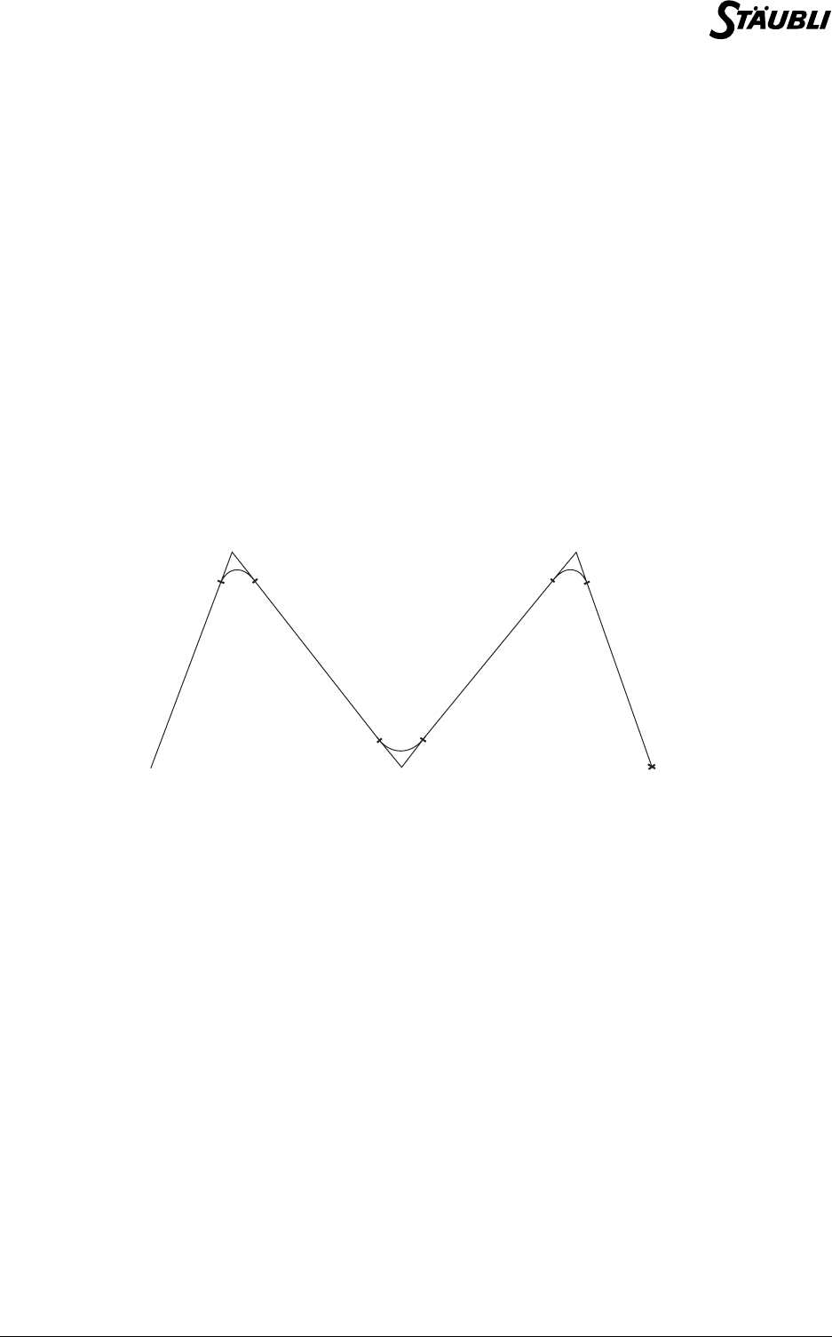
Chapter 9 - Movement control
D28062804A - 02/2006 129 / 160
The fact of executing the instruction lines only records the successive movement commands. The robot
then performs them according to its capabilities. The memory in which the movements are stored is large,
to allow the system to optimize the trajectory. Nevertheless, it is limited. When it is full, the program stops
at the next movement instruction. It resumes when the robot has completed the current movement, thus
creating space in the system memory.
9.2.2. ANTICIPATION AND BLENDING
This section examines in detail what happens when the movements are sequenced. Let us look again at
the previous example:
movej (A, tool, mDesc)
movej (B, tool, mDesc)
movej (C, tool, mDesc)
movej (D, tool, mDesc)
Let us assume that blending is activated in the movement descriptor, mDesc. When the first line is
executed, the system does not yet know what the next movement will be. Only the movement between the
start point and the Aleave point is fully determined, as the Aleave point is defined by the system from the
movement descriptor leave data (see the figure below).
Blended cycle
Until the second line is executed, the part of the blending trajectory in the vicinity of point A has not been
fully determined, as the system has not yet taken the next movement into account. In single-step mode,
the robot does not go further than the Aleave point. When the next instruction is executed, the blending
trajectory in the vicinity of point A (between Aleave and Areach) can be defined, together with the
movement as far as point Bleave. The robot can then proceed to Bleave. In single-step mode, it will not go
beyond this point until the user executes the third instruction, and so on.
The advantage of this operating mode is that the robot passes through exactly the same position in single-
step mode as in normal program execution mode.
9.2.3. SYNCHRONIZATION
The anticipation mechanism causes desychronization between the VAL3 instruction lines and the
corresponding robot movements: the VAL3 program is ahead of the robot.
When it is necessary to carry out an action at a given robot position, the program has to wait for the robot
to complete its movements: the waitEndMove() instruction is used for synchronization purposes.
A
B
C
D
A leave A reach
B leave B reach
C leave C reach

130 / 160 D28062804A - 02/2006
Thus in the following program:
movej(A, tool, mDesc)
movej(B, tool, mDesc)
waitEndMove()
movej(C, tool, mDesc)
movej(D, tool, mDesc)
etc.
The first two lines are executed when the robot starts to move towards A. The program is then blocked at
the third line until the robot is stabilized at point B. When the robot movement is stabilized at B, the
program resumes.
The open() and close() instructions also wait for the robot to comlete its movements before activating the
tool.
9.3. SPEED MONITORING
9.3.1. PRINCIPLE
The principle of monitoring the speed along a trajectory is as follows:
The robot moves and accelerates at all times to its maximum capacity, in accordance with the speed and
acceleration constraints imposed by the movement command.
The movement commands contain two types of speed constraints defined in a mdesc type variable:
Acceleration determines the rate at which the speed increases at the beginning of a trajectory. Conversely,
deceleration determines the rate at which the speed decreases at the end of the trajectory. When high
acceleration and deceleration values are used, the movements are faster, but jerkier. With low values, the
movements take a little longer, but they are smoother.
9.3.2. SIMPLE SETTINGS
When the tool and the object carried by the robot do not need to be handled with special care, Cartesian
speed constraints are not necessary. The speed along the trajectory is normally adjusted as follows:
9.3.3. ADVANCED SETTINGS
To control the Cartesian speed of the tool, for example to execute a trajectory at a constant speed,
proceed as follows:
1. The revolute speed, acceleration and deceleration constraints
2. The Cartesian speed constraints for the tool center point
1. Set the Cartesian speed constraints very high, for example to the default values, to ensure that they
do not affect the rest of the setting procedure.
2. Initialize the revolute speeds and accelerations using the nominal values (100%).
3. Then adjust the speed along the trajectory using the revolute speed parameter.
4. If the speed is not sufficient, increase the acceleration and deceleration parameters
1. Set the Cartesian speed constraints to the values required.
2. Initialize the revolute speeds and accelerations using the nominal values (100%).
3. Then adjust the speed along the trajectory using the Cartesian speed parameter only.
4. If the speed is not sufficient, increase the acceleration and deceleration parameters.
If you want to brake automatically in sections with pronounced curves, reduce the acceleration and
deceleration parameters.

Chapter 9 - Movement control
D28062804A - 02/2006 131 / 160
9.3.4. ENVELOPPE ERROR
The nominal values for revolute speed and acceleration are the nominal load values supported by the
robot, irrespective of trajectory.
However, the robot can often operate faster: the maximum speeds that can be reached by the robot
depend on its load and trajectory. In suitable cases (light load, positive gravitational effect) the robot can
exceed its nominal values without any damage being caused.
If the robot is carrying a load that is heavier than its nominal load, or if the revolute speed and acceleration
values are too high, the robot cannot always obey its movement command and stops when an enveloppe
error occurs. Such errors can be avoided by specifying lower revolute speed and acceleration parameters.
9.4. REAL-TIME MOVEMENT CONTROL
The movement commands previously described in this manual have no immediate effect: when each
command is executed, a movement order is stored in the system. The robot then executes the stored
movements.
The robot's movements can be controlled instantly, as follows:
•The monitor speed modifies the speed of all the movements. It can only be adjusted via the robot's
manual control teach pendant, and not in a VAL3 application. However, the speedScale() instruction
allows an application to know the current monitor speed and hence, if necessary, ask the user to
reduce it when the cycle resumes, or set it to 100% during production.
•The stopMove() and restartMove() instructions are used to stop and restart movement along the
trajectory.
•The resetMotion() instruction is used to stop the movement in progress and cancel the stored
movement commands.
•The Alter instruction (option) applies to the path a geometrical transformation (translation, rotation,
rotation at the tool centre point) that is immediately effective.
CAUTION:
In the case of straight line movements near a singularity, a small tool movement
requires large revolute movements. If the revolute speed is set too high, the robot
cannot obey the command and stops when an enveloppe error occurs.
S5.3

132 / 160 D28062804A - 02/2006
9.5. MDESC TYPE
9.5.1. DEFINITION
The mdesc type is used to define the movement parameters (speed, acceleration, blending).
The mdesc type is a structured type, with the following fields, in this order:
A detailed explanation of these parameters is given at the beginning of the chapter entitled
"Movement control".
By default, an mdesc type variable is initialized at {100,100,100,9999,9999,off,50,50}.
9.5.2. OPERATORS
In ascending order of priority:
num accel Maximum permitted revolute acceleration as a % of the nominal acceleration of the
robot.
num vel Maximum permitted revolute speed as a % of the nominal speed of the robot.
num decel Maximum permitted revolute deceleration as a % of the nominal deceleration of the
robot.
num tvel Maximum permitted translational speed of the tool center point, in mm/s or inches/s
depending on the unit of length of the application.
num rvel Maximum permitted rotational speed of the tool center point, in degrees per second.
blend
blend Blend mode: off (no blending), or joint (blending).
num leave In joint blend mode, distance between the target point at which blending starts and
the next point, in mm or inches, depending on the unit of length of the application.
num reach In joint blend mode, distance between the target point at which blending stops and
the next point, in mm or inches, depending on the unit of length of the application.
mdesc <mdesc& desc1> = <mdesc desc2> Assigns each desc2 field to the field corresponding
to the desc1 variable.
bool <mdesc desc1> != <mdesc desc2> Returns true if the difference between desc1 and
desc2 is at least one field.
bool <mdesc desc1> == <mdesc desc2> Returns true if desc1 and desc2 have the same
field values.

Chapter 9 - Movement control
D28062804A - 02/2006 133 / 160
9.6. MOVEMENT INSTRUCTIONS
void movej(joint joint, tool tool, mdesc desc)
Syntax
void movej(joint joint, tool tool, mdesc desc)
void movej(point point, tool tool, mdesc desc)
Function
Records a command for a revolute movement towards the point or joint positions, using the tool and the
desc movement parameters.
A detailed explanation of the movement parameters is given at the beginning of the chapter
entitled "Movement control".
An execution error is generated if desc contains invalid values, if position is outside the software limits, if
point cannot be reached, or if a previously saved movement command cannot be run (destination out of
reach).
Parameter
See also
void movel(point point, tool tool, mdesc desc)
bool isInRange(joint jPosition)
void waitEndMove()
void movec(Point intermediate, Point target, tool tool, mdesc desc)
CAUTION:
The system does not wait for the movement to be completed before proceeding to the
next VAL3 instruction: several movement commands can be stored in advance. When
the system has used up all its available memory and has no room for another command,
the instruction waits until the new command can be stored.
tool tool Tool type expression
mdesc desc Movement descriptor type expression
joint joint Joint type expression
point point Point type expression

134 / 160 D28062804A - 02/2006
void movel(point point, tool tool, mdesc desc)
Syntax
void movel(point point, tool tool, mdesc desc)
Function
Records a command for a linear movement towards a point position, using the tool tool and the desc
movement parameters.
A detailed explanation of the movement parameters is given at the beginning of the chapter
entitled "Movement control".
An execution error is generated if desc contains invalid values, if point cannot be reached, if a straight line
movement towards point is not possible or if a previously saved movement command cannot be run
(destination out of reach).
Parameter
See also
void movej(joint joint, tool tool, mdesc desc)
void waitEndMove()
void movec(Point intermediate, Point target, tool tool, mdesc desc)
CAUTION:
The system does not wait for the movement to be completed before proceeding to the
next VAL3 instruction: several movement commands can be stored in advance. When
the system has used up all its available memory and has no room for another command,
the instruction waits until the new command can be stored.
point point Point type expression.
tool tool Tool type expression.
mdesc desc Movement descriptor type expression.

Chapter 9 - Movement control
D28062804A - 02/2006 135 / 160
void movec(Point intermediate, Point target, tool tool, mdesc desc)
Syntax
void movec(Point intermediate, Point target, tool tool, mdesc desc)
Function
Records a command for a circular movement starting from the destination of the previous movement and
finishing at Point target and passing through the Point intermediate.
The tool orientation is interpolated in such a way that it is possible to program a constant orientation in
absolute terms, or as compared with the trajectory.
A detailed explanation of the various movement parameters and orientation interpolation can be
found at the beginning of the "Movement Control" chapter.
An execution error is generated if desc has invalid values, if Point intermediate (or Point target) cannot
be reached, if the circular movement is not possible (see the "Movement control - interpolation of
orientation" chapter), or if a movement command recorded beforehand cannot be executed (destination
out of reach).
Parameter
See also
void movej(joint joint, tool tool, mdesc desc)
void movel(point point, tool tool, mdesc desc)
void waitEndMove()
CAUTION:
The system does not wait for the movement to be completed before proceeding to the
next VAL3 instruction: several movement commands can be stored in advance. When
the system has used up all its available memory and has no room for another command,
the instruction waits until the new command can be stored.
Point intermediate Point type expression.
Point target Point type expression.
tool tool Tool type expression.
mdesc desc Movement descriptor type expression.

136 / 160 D28062804A - 02/2006
void stopMove()
Syntax
void stopMove()
Function
Stops the arm on the trajectory and suspends authorization of the programmed movement.
The kinematic parameters used to execute the stop are those used for the current movement.
The movements can only be resumed after a restartMove() or resetMotion() instruction.
Non-programmed movements ( jog interface) are still possible.
Example
See also
void restartMove()
void resetMotion(), void resetMotion(joint startingPoint)
void resetMotion(), void resetMotion(joint startingPoint)
Syntax
void resetMotion()
void resetMotion(joint startingPoint)
Function
Stops the arm on the trajectory and cancels all the stored movement commands.
The programmed movement authorization is restored if it was suspended by the stopMove() instruction.
If the startingPoint revolute position is specified, the next movement command can only be run from this
position: a connection movement must be performed beforehand to reach the startingPoint position.
If no revolute position is specified, the next movement command is run from the arm's current position,
wherever it is.
See also
bool isEmpty()
void stopMove()
void autoConnectMove(bool active), bool autoConnectMove()
CAUTION:
This instruction returns immediately: the VAL3 task does not wait for the movement to
be completed before proceeding to the next instruction.
wait (dSignal==true) // waits for a signal
stopMove() // stops movements along the trajectory
<instructions>
restartMove() // restarts movements along the trajectory
CAUTION:
This instruction returns immediately: the VAL3 task does not wait for the movement to
be completed before proceeding to the next instruction.

Chapter 9 - Movement control
D28062804A - 02/2006 137 / 160
void restartMove()
Syntax
void restartMove()
Function
Restores the programmed movement authorization, and restarts the trajectory interrupted by the
stopMove() instruction.
If the programmed movement authorization was not interrupted by the stopMove() instruction, this
intruction has no effect.
See also
void stopMove()
void resetMotion(), void resetMotion(joint startingPoint)
void waitEndMove()
Syntax
void waitEndMove()
Function
Cancels the blending of the last movement commmand recorded and waits for the command to be
executed.
This instruction does not wait for the robot to be stabilized in its final position, it only waits until the position
instructions sent to the variable speed drives correspond to the desired final position. When it is necessary
to wait for complete stabilization of the movement, the isSettled() instruction must be used.
An execution error is generated if a previously stored movement cannot be run (destination out of reach).
Example
See also
bool isSettled()
bool isEmpty()
void stopMove()
void resetMotion(), void resetMotion(joint startingPoint)
waitEndMove()
putln(sel(isEmpty(),1,-1)) // displays 1, no more commands in progress
putln(sel(isSettled(),1,-1)) // May display -1, the robot is not necessarily already stabilized
watch(isSettled(), 1) // Waits for the robot to stabilize for 1 s maximum

138 / 160 D28062804A - 02/2006
bool isEmpty()
Syntax
bool isEmpty()
Function
Returns true if all the movement commands have been executed, returns false if at least one command is
still being executed.
Example
// If commands are in progress
if ! isEmpty()
//Stop the robot and cancel the commands
resetMotion()
endIf
See also
void waitEndMove()
void resetMotion(), void resetMotion(joint startingPoint)
bool isSettled()
Syntax
bool isSettled()
Function
Returns true if the robot is stopped, and false if its position is not yet stabilized.
The position is considered as stabilized if the position error for each joint remains less than 1% of the
maximum authorized position, for 50 ms.
See also
bool isEmpty()
void waitEndMove()
void autoConnectMove(bool active), bool autoConnectMove()
Syntax
void autoConnectMove(bool active)
bool autoConnectMove()
Function
In the remote mode, the connection movement is automatic if the arm is very close to its trajectory
(distance less than the maximum authorized drift error). If the arm is too far away from its trajectory, the
connection movement is automatic or under manual control depending on the mode defined by the
autoConnectMove instruction: automatically if active is true, in manual control mode if active is false.
When called without parameters, autoConnectMove returns the current connection movement mode.
By default, the connection movement in remote mode is under manual control.
See also
void resetMotion(), void resetMotion(joint startingPoint)
CAUTION:
Under normal conditions of use, the arm stops on its trajectory during an emergency
stop. Hence in remote mode, the arm is able to restart automatically whatever the
connection movement defined by the autoConnectMove instruction.


Chapter 10 - Options
D28062804A - 02/2006 141 / 160
10.1. COMPLIANT MOVEMENTS WITH FORCE CONTROL
10.1.1. PRINCIPLE
In a standard movement command, the robot moves to reach a requested position at a programmed rate
of acceleration and speed. If the arm cannot follow the command, additional force will be requested from
the motors in order to attempt to reach the desired position. When the deviation between the position set
by the command and the true position is too great, a system error is generated that cuts off power to the
robot arm.
The robot is said to be 'compliant' when it accepts certain deviation between the position set by command
and the actual position. The CS8 can be programmed to be trajectory compliant, i.e. to accept a delay or
advance in relation to the programmed trajectory, by controlling the force applied by the arm. On the other
hand, no deviation in relation to the trajectory is allowed.
In practice, the CS8's compliant movements can allow the arm to follow a trajectory while being pushed or
pulled by an outside force, or come into contact with an object, with a check made on the force applied by
the arm on the object.
10.1.2. PROGRAMMING
Compliant movements are programmed like standard movements, using the movelf() and movejf()
instructions, with an additional parameter used to control the force applied by the arm. During the
compliant movement, speed and acceleration limits are applied, in the same way as for standard
movements, via the movement descriptor. The movement can take place along the trajectory, in either
direction.
It is possible to combine compliant movements or combine compliant and standard movements: as soon
as the destination position is reached, the robot moves on to the next movement. The waitEndMove()
instruction is used to wait for the end of a compliant movement.
The resetMotion() instruction cancels all programmed movements, whether compliant or not. After
resetMotion(), the robot is no longer compliant.
The stopMove() and restartMove() instructions also apply to compliant movements:
The stopMove() forces the current movement speed to zero. If it is a compliant movement, it is hence
stopped and the robot is no longer compliant until the restartMove() instruction is run.
Lastly, the isCompliant() instruction is used to ensure that the robot is in compliant mode, for example
before allowing any outside force to be applied to the arm.
10.1.3. FORCE CONTROL
When the specified force parameter is null, the arm is passive, i.e. it only moves when actuated by outside
forces.
When the force parameter is positive, everything operates as though an outside force were pushing the
arm to the position ordered: the arm moves on its own, but it can be held back or accelerated by outside
action which is added to the force commanded.
When the force parameter is negative, everything operates as though an outside force were pushing the
arm towards its initial position: to move the arm towards the position commanded, it is thus necessary to
apply an outside force that is greater than the force commanded.
The force parameter is expressed as a percentage of the arm's nominal load. 100% means that the arm
applies a force towards the position commanded, that is equivalent to the nominal load. In rotation, 100%
corresponds to the nominal torque allowed on the arm.
When the arm's speed or acceleration reach the values specified in the movement descriptor, the robot
opposes its full power to resist any attempt to increase its speed or rate of acceleration.

142 / 160 D28062804A - 02/2006
10.1.4. LIMITATIONS
Compliant movements present the following limitations:
-It is not possible to use blending at the start or the end of a compliant movement: the arm is bound
to stop at the start and end of every compliant movement.
-When a compliant movement is made, the arm may move back to its starting point, but it cannot
move back any further: the arm then stops suddenly at its starting point.
-The force parameter on the arm cannot exceed 1000%. The precision obtained concerning the
force applied is limited by internal friction. It depends mainly on the arm position and the trajectory
commanded.
-Long compliant movements require a lot of internal memory capacity. An execution error is
generated if the system does not have enough memory to fully process the movement.
10.1.5. INSTRUCTIONS
void movejf(joint position, tool tool, mdesc desc, num force)
Syntax
void movejf(joint position, tool tool, mdesc desc, num force)
Function
Records a compliant revolute movement command towards the position position using the tool tool, the
desc movement parameters, and a force force command.
The force force command is expressed as a percentage of the maximum arm force and cannot exceed
±1000%.
A detailed explanation of the various movement parameters is given at the beginning of the section.
An execution error is generated if desc or force have invalid values, if position is outside the software
limits, if the previous movement required blending or if a previously recorded movement command cannot
be run (destination out of reach).
Parameter
See also
void movelf(point point, tool tool, mdesc desc, num force)
bool isCompliant()
CAUTION:
The system does not wait for the movement to be completed before proceeding to the
next VAL3 instruction: several movement commands can be stored in advance. When
the system has used up all its available memory and has no room for another command,
the instruction waits until the new command can be stored.
tool tool Tool type expression.
mdesc desc Movement descriptor type expression
joint position Revolute position type position
num force Numerical type expression

Chapter 10 - Options
D28062804A - 02/2006 143 / 160
void movelf(point point, tool tool, mdesc desc, num force)
Syntax
void movelf(point point, tool tool, mdesc desc, num force)
Function
Records a compliant linear movement command towards the point position using the tool tool, the desc
movement parameters and the force force command.
The force force command is expressed as a percentage of the maximum arm force and cannot exceed
±1000%.
A detailed explanation of the various movement parameters is given at the beginning of the section.
An execution error is generated if desc or force have invalid values, if point cannot be reached, if
movement towards point is impossible in a straight line, if the previous movement required blending or if a
previously recorded movement command cannot be run (destination out of reach).
Parameter
See also
void movejf(joint position, tool tool, mdesc desc, num force)
bool isCompliant()
CAUTION:
The system does not wait for the movement to be completed before proceeding to the
next VAL3 instruction: several movement commands can be stored in advance. When
the system has used up all its available memory and has no room for another command,
the instruction waits until the new command can be stored.
point point Point type expression.
tool tool Tool type expression
mdesc desc Movement descriptor type expression
num force Numerical type expression

144 / 160 D28062804A - 02/2006
bool isCompliant()
Syntax
bool isCompliant()
Function
Returns true if the robot is in compliant mode, otherwise returns false.
Example
See also
void movelf(point point, tool tool, mdesc desc, num force)
void movejf(joint position, tool tool, mdesc desc, num force)
movelf(position, Tool, mDesc, 0)
wait(isCompliant()) // Waits for the robot to actually be in compliant mode
dEjection = true // Commands press ejection
waitEndMove() // Waits for the end of compliant movement
movej(jDepart, Tool, mDesc) // Continues with a standard movement

Chapter 10 - Options
D28062804A - 02/2006 145 / 160
10.2. ALTER: REAL TIME CONTROL ON A PATH
Cartesian Alter
10.2.1. PRINCIPLE
A Cartesian alteration of a path allows apply to the path a geometrical transformation (translation, rotation,
rotation at the tool centre point) that is immediately effective.
This feature makes it possible to modify a nominal path using an external sensor, for, for example, track
accurately the shape of a part, or operate on a moving part.
10.2.2. PROGRAMMING
The programming consists in defining first the nominal path, then, in real time, specifying a deviation to it.
The nominal path is programmed as for standard moves, with the alterMovel(), alterMovej() and
alterMovec() instructions. Several alterable moves may succeed, or some alterable moves may alternate
with not alterable moves. We will define the alterable path as the successive alterable move commands
between two not alterable move commands.
The alteration itself is programmed with the alter() instruction. Different alter modes are possible
depending on the geometrical transformation to apply; the mode is defined with the alterBegin()
instruction. The alterEnd() instruction is finally needed to specify how to terminate the altering, either
before the nominal move is completed, so that the next non alterable move can be sequenced without
stop; either after, so that it remains possible to move the arm with alter while the nominal move is stopped.
The other motion control instructions remains effective in alter mode.
10.2.3. CONSTRAINTS
Synchronisation, desynchronisation: Because the alter command is applied immediately, the change in the
alteration must be controlled so that the resulting arm path remains without discontinuity or noise:
•A large change in the alteration can only be applied gradually with a specific approach control.
•The end of the altering requires a null alteration speed, obtained gradually with a specific stop control.
Synchronous command: The controller sends position and velocity commands every 4ms to the
amplifiers. As a consequence, the alter command must be synchronized with this communication period so
that the alteration speed remains under control. This is done by using a synchronous VAL3 task (see
Tasks chapter). In the same way, the sensor input may have to be filtered first if the data is noisy or if its
sampling period is not synchronized with the controller period.
Smooth sequencing: The first non alterable move following an alterable path can be computed only when
alterEnd is executed. As a consequence, if alterEnd is executed too near the end of the alterable move,
the arm may slow down or even stop near this point, until the next move is computed.
Moreover, the ability to compute in advance the next move imposes some restrictions on the altered path
after alterEnd is executed: It must then keep the same configuration, and make sure all joints remain in the
same axis turn. It is then possible that an error is generated during the move that would not occur if
alterEnd was not executed in advance.
CAUTION:
The waitEndMove, open and close instructions wait for the end of the nominal move,
not for the end of altered move. VAL3 execution may therefore resume after a
waitEndMove even if the arm is still moving because of a changing alter deviation.

146 / 160 D28062804A - 02/2006
10.2.4. SAFETY
At any time, the user alteration may be invalid: target out of reach, velocity or acceleration too high. When
the system detects such situations, an error is generated and the arm is stopped suddenly at the last valid
position. The motion needs to be reset to resume operation.
When the arm motion is disabled during a move (hold mode, stop request or emergency stop), a stop is
controlled on the nominal move as for standard moves. After a certain delay, the alter mode is also
automatically disabled to guaranty a complete stop of the arm. When the stop condition disappears, the
move may resume and the alter mode is automatically enabled again.
10.2.5. LIMITATIONS
A null move (when the move target is on start position) is ignored by the system. As a consequence, you
need a not null move to enter the alter mode.
It is not possible to specify the desired configuration for the altered path; the system always uses the same
configuration. It is therefore not possible to change the configuration of the arm within an altered path
(even with the alterMovej instruction).
10.2.6. INSTRUCTIONS
void alterMovej(joint target, tool tcp, mdesc speed)
Syntax
void alterMovej(joint target, tool tcp, mdesc speed)
void alterMovej(point target, tool tcp, mdesc speed)
Function
Register an alterable joint move command (a line in the joint space)
Parameter
Details
This instruction behaves exactly as the movej instruction, except that it enables the alter mode for the
move. See movej for more details.
target Point or joint expression defining the end position of the move.
tcp Tool expression defining the tool centre point used during the move
for Cartesian speed control.
speed mdesc expression defining the speed control and blending
parameter for the move.

Chapter 10 - Options
D28062804A - 02/2006 147 / 160
void alterMovel(point target, tool tcp, mdesc speed)
Syntax
void alterMovel(point target, tool tcp, mdesc speed)
Function
Register an alterable linear move command (a line in the Cartesian space)
Parameter
Details
This instruction behaves exactly as the movel instruction, except that it enables the alter mode for the
move. See movel for more details.
void alterMovec
(point intermediate, point target, tool tcp, mdesc speed)
Syntax
void alterMovec(point intermediate, point target, tool tcp, mdesc speed)
Function
Register an alterable circular move command.
Parameter
Details
This instruction behaves exactly as the movec instruction, except that it enables the alter mode for the
move. See movec for more details.
target Point expression defining the end position of the move.
tcp Tool expression defining the tool centre point used during the
move for Cartesian speed control. At the end of the move, the tool
centre point is at the specified target position.
speed mdesc expression defining the speed control and blending
parameter for the move.
Intermediate Point expression defining an intermediate point on the circle
target Point expression defining the end position of the move.
tcp Tool expression defining the tool centre point used during the move
for Cartesian speed control. At the end of the move, the tool centre
point is at the specified target position.
speed mdesc expression defining the speed control and blending
parameter for the move.

148 / 160 D28062804A - 02/2006
num alterBegin(frame alterReference, mdesc velocity)
num alterBegin(tool alterReference, mdesc velocity)
Syntax
num alterBegin(frame alterReference, mdesc velocity)
num alterBegin(tool alterReference, mdesc velocity)
Function
Initialize the alter mode for the alterable path being executed.
Parameter
Details
The alter mode initiated with alterBegin terminates only with an alterEnd command, or a resetMotion.
When the end of an alterable path is reached, the alter mode remains active until alterEnd is executed.
The trsf expression of the alter command defines a transformation of the whole path around
alterReference:
•The path is rotated around the centre of the frame or tool using the rotation part of the trsf.
•Then the path is translated by the translation part of the trsf.
The trsf coordinates of the alter command are defined in alterReference base.
When a frame is used as reference, the alterReference is fixed in space (World). This mode must be used
when the deviation of the path is known or measured in the Cartesian space (moving part such as
conveyor tracking).
When a tool is used as reference, the alterReference is fixed relatively to the tool centre point. This mode
must be used when the deviation of the path is known or measured relatively to the tool centre point (for
example part shape sensor mounted on the tool).
The motion descriptor is used to define the maximum joint and Cartesian velocity on the altered path
(using the fields vel, tvel and rvel of the motion descriptor). An error is generated and the arm is stopped
on path if the altered velocity exceeds the specified limits.
The accel and decel fields of the motion descriptor control the stop time when a stop condition occurs
(eStop, hold mode, VAL3 stopMove()): The path alteration must be stopped using these deceleration
parameters (see alterStopTime).
alterBegin returns a numerical value to indicate the result of the instruction:
See also
num alterEnd()
num alter(trsf alteration)
num alterStopTime()
alterReference Frame or tool expression defining the reference for the alter
deviation.
velocity mdesc expression defining the safety check parameters for the
alter deviation.
1 alterBegin was successfully executed
0 alterBegin is waiting for the start of the alterable move
-1 alterBegin was ignored because the alter mode has already started
-2 alterBegin is refused (alter option is not enabled)
-3 alterBegin was refused because the motion is in error. A resetMotion is required.

Chapter 10 - Options
D28062804A - 02/2006 149 / 160
num alterEnd()
Syntax
num alterEnd()
Function
Exit the alter mode and make the current move not alterable any more.
Details
If alterEnd is executed when the end of the alterable path is reached, the next not alterable move (if any) is
started immediately.
If alterEnd is executed before the end of the alterable move, the current value of the alter deviation is
applied to the rest of the alterable path, until the first next not alterable move. It is not possible to enter the
alter mode again on the same alterable path.
The next not alterable move, if any, is computed as soon as alterEnd is executed so that the transition
between the alterable path and the next not alterable move is made without stop.
alterEnd returns a numerical value to indicate the result of the instruction:
See also
num alterBegin(frame alterReference, mdesc velocity)
num alterBegin(tool alterReference, mdesc velocity)
num alter(trsf alteration)
Syntax
num alter(trsf alteration)
Function
Specify a new alteration of the alterable path.
Parameter
Details
The transformation induced by the alteration trsf depends on the alter mode selected by the alterBegin
instruction. The alteration coordinates are defined in the frame or tool specified with the alterBegin
instruction.
The alteration is applied by the system every 4ms: When several alter instructions are executed in less
that 4ms, the last one applies. Most often the alter instruction needs to be executed in a synchronous task
to force an alteration refresh every 4ms.
The alteration must be computed carefully so that the resulting arm position and speed commands remain
continuous and without noise. A sensor input may need to be filtered adequately to reach the desired
quality on the arm path and behaviour.
When the motion is stopped (hold mode, emergency stop, stopMove() instruction), the alteration of the
path is locked until all stop conditions are cleared.
When the alteration of the path is invalid (unreachable position, out of speed limits), the arm will stop
suddenly at the last valid position and the alter mode is locked in error. A resetMotion is required to resume
operation. The velocity limits for the alter move are defined by the alterBegin instruction.
1alterEnd was successfully executed
-1 alterEnd was ignored because the alter mode has not yet started
-3 alterEnd was refused because the motion is in error. A resetMotion is required.
alteration Trsf expression defining the alteration to apply until the next alter
instruction.

150 / 160 D28062804A - 02/2006
Alter returns a numerical value to indicate the result of the instruction:
See also
num alterBegin(frame alterReference, mdesc velocity)
num alterBegin(tool alterReference, mdesc velocity)
void taskCreateSync string name, num period, bool& overrun, program(...)
num alterStopTime()
Syntax
num alterStopTime()
Function
Return the remaining time before the alter deviation is locked, when a stop condition occurs.
Details
When a stop condition occurs, the system evaluates the time to stop the arm if the accel and decel
parameters of the motion descriptor specified with alterBegin are used. The minimum of this time and the
time imposed by the system (typically 0.5s when a eStop occurs) is returned by alterStopTime.
When alterStopTime returns a negative value, there is no pending stop condition. When alterStopTime
returns null, the alter command is locked until all stop conditions are reset.
alterStopTime returns null when the alter mode is not enabled.
See also
num alterBegin(frame alterReference, mdesc velocity)
num alterBegin(tool alterReference, mdesc velocity)
num alter(trsf alteration)
1alter was successfully executed.
0alter is waiting for the motion to restart (alterStopTime is null).
-1 alter was ignored because the alter mode is not started or already ended.
-2 alter is refused (alter option is not enabled).
-3 alter was refused because the motion is in error. A resetMotion is required.


Chapter 11 - Appendix
D28062804A - 02/2006 153 / 160
11.1. EXECUTION ERROR CODES
Code Description
-1 There is no task with the specified name created by this library
0No execution error
1A task is running
10 Invalid numerical calculation (division by zero).
11 Invalid numerical calculation (e.g.ln(-1))
20 Access to a table with an index that is larger than the table size.
21 Access to a table with a negative index.
29 Invalid task name. See taskCreate() instruction.
30 The specified name does not correspond to any VAL3 task.
31 A task with the same name already exists. See taskCreate instruction.
32 Only 2 different periods for synchronous tasks are supported. Change scheduling period.
40 Not enough memory space available.
41 Not enough memory space to run the task. See the run memory size.
60 Maximum instruction run time exceeded.
61 Internal VAL3 interpreter error
70 Invalid instruction parameter. See the corresponding instruction.
80 Uses data or a program from a library not loaded in the memory.
81 Incompatible kinematic: Use of a point/joint/config that is not compatible with the arm kinematic.
90 The task cannot resume from the location specified. See taskResume() instruction.
100 The speed specified in the motion descriptor is invalid (negative or too great).
101 The acceleration specified in the motion descriptor is invalid (negative or too great).
102 The deceleration specified in the motion descriptor is invalid (negative or too great).
103 The sideways speed specified in the motion descriptor is invalid (negative or too great).
104 The rotation speed specified in the motion descriptor is invalid (negative or too great).
105 The reach parameter specified in the movement descriptor is invalid (negative).
106 The leave parameter specified in the movement descriptor is invalid (negative).
122 Attempt to write in a system input.
123 Use of a dio, aio or sio input/output not connected to a system input/output.
124 Attempt to access a protected system input/output
125 Read or write error on a dio, aio or sio (field bus error)
150 Cannot run this movement instruction: a previous movement request could not be completed (point out
of reach, singularity, configuration problem, etc.)
153 Movement command not supported
154 Invalid movement instruction: check the movement descriptor.
160 Invalid flange tool coordinates
161 Invalid world tool coordinates
162 Use of a point without a reference frame. See Definition.
163 Use of a frame without a reference frame. See Definition.
164 Use of a tool without reference tool. See Definition.
165 Invalid frame or reference tool (global variable linked to a local variable)
250 No runtime licence for this instruction, or demo licence is over.
154 / 160 D28062804A - 02/2006
11.2. CONTROL PANEL KEYBOARD KEY CODES
Menus (with or without Shift):
For standard keys, the code returned is the ASCII code of the corresponding character:
Without Shift With Shift
3Caps Space 3Caps Space
283 - 32 Move 283 - 32 Move
Ret. -Ret. -
2Shift Esc Help Run 2Shift Esc Help Run
282 - 255 - 270 - 282 - 255 - 270 -
Menu Tab Up Bksp Stop Menu UnTab PgUp Bksp Stop
- 259 261 263 - - 260 262 263 -
1User Left Down Right 1User Home PgDn End
281 - 264 266 268 281 - 265 267 269
F1 F2 F3 F4 F5 F6 F7 F8
271 272 273 274 275 276 277 278
Without Shift
q w e r t y u i o p
113 119 101 114 116 121 117 105 111 112
a s d f g h j k l <
97 115 100 102 103 104 106 107 108 60
z x c v b n m . , =
122 120 99 118 98 110 109 46 44 61
With Shift
7 8 9 + * ; ( ) [ ]
55 56 57 43 42 59 40 41 91 93
4 5 6 - / ? : ! { }
52 53 54 45 47 63 58 33 123 125
1 2 3 0 " % - . , >
49 50 51 48 34 37 95 46 44 62
With double Shift
Q W E R T Y U I O P
81 87 69 82 84 89 85 73 79 80
A S D F G H J K L }
65 83 68 70 71 72 74 75 76 125
Z X C V B N M $ \ =
90 88 67 86 66 78 77 36 92 61

D28062804A - 02/2006 155 / 160
VAL3 REFERENCE MANUAL - Version 5.3
ILLUSTRATION
Ambiguity as to the intermediate orientation ................................. 125
Blended cycle ..................................................... 122
Blended cycle ..................................................... 129
Circular movement .................................................. 120
Configuration change: righty / lefty ....................................... 126
Configuration: enegative .............................................. 114
Configuration: epositive............................................... 114
Configuration: lefty .................................................. 113
Configuration: lefty .................................................. 115
Configuration: righty ................................................. 113
Configuration: righty ................................................. 115
Configuration: wnegative .............................................. 114
Configuration: wpositive .............................................. 114
Constant orientation as compared with the trajectory ........................... 124
Constant orientation in absolute terms ..................................... 124
Cycle type: U...................................................... 120
Cycle without blending at a given point..................................... 122
Definition of the distances: ’leave’ / ’reach’ .................................. 121
Elbow configuration change impossible .................................... 127
Frame rotation about the axis: X .......................................... 98
Frame rotation about the axis: Y’.......................................... 99
Frame rotation about the axis: Z’’ ......................................... 99
Full circle ........................................................ 125
Initial and final positions .............................................. 119
Links between reference frames ......................................... 101
Links between tools ................................................. 103
Organization chart: frame / point / tool / trsf ................................... 92
Orientation ........................................................ 98
Point definition..................................................... 105
Positive/negative elbow configuration change ................................ 126
Positive/negative wrist configuration change ................................. 127
Sequencing........................................................ 68
Shoulder configuration change possible .................................... 128
Straight line movement ............................................... 119
Two configurations that can be used to reach a given point: P ..................... 112
User page......................................................... 59


D28062804A - 02/2006 157 / 160
VAL3 REFERENCE MANUAL - Version 5.3
A
abs (fonction) 34, 93
accel 132
acos (fonction) 33
aio 19, 51
aioGet (fonction) 51
aioLink (fonction) 51
aioSet (fonction) 52
appro (fonction) 108
asc (fonction) 43
asin (fonction) 33
atan (fonction) 34
autoConnectMove 123
autoConnectMove (fonction) 138
B
blend 121, 132
bool 19
C
call 18, 23
call (fonction) 22
chr (fonction) 42
clearBuffer (fonction) 54
clock (fonction) 78
close 68
close (fonction) 104
cls (fonction) 60
codeAscii 42
compose (fonction) 107
config 19, 92, 111
config (fonction) 115
cos (fonction) 33
D
decel 132
delay 68
delay (fonction) 77
delete (fonction) 45
dio 19, 48
dioGet (fonction) 49
dioLink (fonction) 49
dioSet (fonction) 50
disablePower (fonction) 87
distance (fonction) 100, 106
do 24
do ... until (fonction) 24
E
elbow 112
else 23
enablePower (fonction) 87
endFor 25
endIf 23
endWhile 24
enegative 114
epositive 114
esStatus (fonction) 89
exp (fonction) 35
F
find (fonction) 46
flange 17
for 25
for (fonction) 25
frame 19, 92
G
get 68
get (fonction) 61
getKey (fonction) 63
getLatch (fonction) 96
globale 20
gotoxy (fonction) 60
H
here (fonction) 108
herej (fonction) 94
I
if (fonction) 23
insert (fonction) 45
isCalibrated (fonction) 88
isCompliant 141
isCompliant (fonction) 144, 146, 147, 148, 149, 150
isEmpty (fonction) 138
isInRange (fonction) 94
isKeyPressed (fonction) 63
isPowered (fonction) 87
isSettled (fonction) 138
J
joint 19
jointToPoint (fonction) 109
INDEX

158 / 160 D28062804A - 02/2006
L
leave 121, 132
left (fonction) 43
lefty 113, 115
len (fonction) 47
libDelete (fonction) 83
libList (fonction) 84
libLoad 82
libLoad (fonction) 83
libPath (fonction) 84
libSave (fonction) 83
limit (fonction) 38
ln (fonction) 36
locale 20
log (fonction) 36
logMsg (fonction) 64
M
max (fonction) 38
mdesc 19, 119, 132
mid (fonction) 44
min (fonction) 38
movec (fonction) 135
movej 119
movej (fonction) 133
movejf 141
movejf (fonction) 142
movel 119
movel (fonction) 134
movelf 141
movelf (fonction) 143
N
num 19, 43
O
open 68
open (fonction) 104
P
point 19
pointToJoint (fonction) 109
popUpMsg (fonction) 63
position (fonction) 110
put (fonction) 60
putln 60
R
reach 121, 132
replace (fonction) 46
resetMotion 123, 136, 141
resetMotion (fonction) 136
restartMove 136, 141
restartMove (fonction) 137
return (fonction) 23
right (fonction) 44
righty 113, 115
round (fonction) 37
roundDown (fonction) 37
roundUp (fonction) 37
RUNNING 77, 78
rvel 132
S
sel (fonction) 39
setFrame (fonction) 102
setLatch (fonction) 95
setMutex (fonction) 73
shoulder 112
sin (fonction) 32
sio 19, 53
sioGet (fonction) 54
sioLink (fonction) 54
sioSet (fonction) 55
size (fonction) 29
speedScale (fonction) 89
sqrt (fonction) 35
start 17
stop 17
stopMove 141
stopMove (fonction) 136
STOPPED 72
string 19
switch (fonction) 26
T
tan (fonction) 34
taskCreate (fonction) 75, 76
taskKill (fonction) 73
taskResume 67
taskResume (fonction) 72
taskStatus 67
taskStatus (fonction) 74
taskSuspend (fonction) 72
title (fonction) 61
toNum (fonction) 41
tool 19, 92
toString (fonction) 40
trsf 19, 92
tvel 132

D28062804A - 02/2006 159 / 160
VAL3 REFERENCE MANUAL - Version 5.3
U
until 24
userPage (fonction) 59
V
vel 132
void setLatch(dio input) (CS8C only) 95
void setMutex (bool& mutex) 73
W
wait 68
wait (fonction) 77
waitEndMove 68, 122, 141
waitEndMove (fonction) 137
watch 68
watch (fonction) 78
while (fonction) 24
wnegative 114
workingMode (fonction) 88
world 17
wpositive 114
wrist 112

