VxWorks BSP Developer's Guide, 6.6 Developers Guide
User Manual:
Open the PDF directly: View PDF ![]() .
.
Page Count: 226 [warning: Documents this large are best viewed by clicking the View PDF Link!]
- VxWorks BSP Developer's Guide, 6.6
- Contents
- 1 Introduction
- 2 Overview of a BSP
- 3 Porting a BSP to Custom Hardware
- 3.1 Introduction
- 3.2 Getting a Default Kernel Running
- 3.2.1 Initializing the Board
- 3.2.2 Initializing Memory
- 3.2.3 Using Debug Routines in the Initialization Code
- 3.2.4 VxBus Initialization Sequence
- 3.2.5 Debugging the Initialization Code
- 3.2.6 Starting the WDB Agent Before the Kernel
- 3.2.7 Building and Downloading VxWorks
- 3.2.8 Interrupt Controllers
- 3.2.9 DMA
- 3.2.10 Minimum Required Drivers
- 3.2.11 Serial Drivers
- 3.2.12 VxBus Initialization Routines
- 3.3 Finalizing Your BSP
- 3.3.1 Removing Development-Related Changes
- 3.3.2 Creating Workbench Projects
- 3.3.3 Adding Other Timers
- 3.3.4 Enabling NVRAM
- 3.3.5 Enabling Cache and MMU Devices
- 3.3.6 Testing Boot ROMs
- 3.3.7 Providing Bus Interface Support
- 3.3.8 Updating BSP-Specific Documentation
- 3.3.9 Providing Additional Optional Device Support
- 3.3.10 Writing Generic Drivers
- 3.3.11 Troubleshooting and Debugging
- 3.3.12 Modifying a BSP to Support Kernel Scalability
- 4 Debugging Your BSP
- A Resolving Common Development Issues
- B Implementing Documentation Guidelines
- C BSP Validation Test Suite
- Index

VxWorks
BSP DEVELOPER'S GUIDE
®
6.6
VxWorks BSP Developer's Guide, 6.6

Copyright © 2007 Wind River Systems, Inc.
All rights reserved. No part of this publication may be reproduced or transmitted in any
form or by any means without the prior written permission of Wind River Systems, Inc.
Wind River, Tornado, and VxWorks are registered trademarks of Wind River Systems, Inc.
The Wind River logo is a trademark of Wind River Systems, Inc. Any third-party
trademarks referenced are the property of their respective owners. For further information
regarding Wind River trademarks, please see:
http://www.windriver.com/company/terms/trademark.html
This product may include software licensed to Wind River by third parties. Relevant
notices (if any) are provided in your product installation at the following location:
installDir/product_name/3rd_party_licensor_notice.pdf.
Wind River may refer to third-party documentation by listing publications or providing
links to third-party Web sites for informational purposes. Wind River accepts no
responsibility for the information provided in such third-party documentation.
Corporate Headquarters
Wind River Systems, Inc.
500 Wind River Way
Alameda, CA 94501-1153
U.S.A.
toll free (U.S.): (800) 545-WIND
telephone: (510) 748-4100
facsimile: (510) 749-2010
For additional contact information, please visit the Wind River URL:
http://www.windriver.com
For information on how to contact Customer Support, please visit the following URL:
http://www.windriver.com/support
VxWorks BSP Developer's Guide, 6.6
5 Nov 07
Part #: DOC-16097-ND-00

iii
Contents
1 Introduction .......................................................................................... 1
1.1 About This Document ........................................................................................... 1
1.2 The Board Support Package ................................................................................. 2
1.3 The BSP Development Process ............................................................................ 3
1.4 Terminology ............................................................................................................. 4
2 Overview of a BSP ............................................................................... 7
2.1 Introduction ............................................................................................................. 7
2.2 Boot Sequence ......................................................................................................... 10
2.2.1 Sequence Overview ................................................................................. 10
2.2.2 Boot Sequence Configurations ............................................................... 12
2.2.3 Architecture Considerations ................................................................... 16
2.2.4 Detailed Boot Sequence ........................................................................... 17
2.3 Components of a BSP ............................................................................................ 22

VxWorks
BSP Developer's Guide, 6.6
iv
2.3.1 Source and Include Files .......................................................................... 23
README ................................................................................................... 24
Makefile ..................................................................................................... 25
config.h ...................................................................................................... 25
bspname.h ................................................................................................. 25
sysALib.s .................................................................................................... 26
romInit.s ..................................................................................................... 26
sysLib.c ....................................................................................................... 27
target.ref or target.nr ................................................................................ 28
board.jpg .................................................................................................... 28
sysDev.c ...................................................................................................... 28
configAll.h ................................................................................................. 29
bootInit.c .................................................................................................... 30
usrConfig.c ................................................................................................ 30
2.3.2 Derived Files ............................................................................................. 30
2.3.3 Required Data Variables ......................................................................... 31
sysPhysMemDesc[ ] ................................................................................. 32
sysPhysMemDescNumEnt ..................................................................... 33
sysBootLine ............................................................................................... 33
sysExcMsg ................................................................................................. 34
sysFlags ...................................................................................................... 34
hcfDeviceList[ ] ......................................................................................... 34
hcfDeviceNum .......................................................................................... 34
devUnitCfgData[ ] .................................................................................... 34
2.3.4 Required Routines .................................................................................... 35
sysBspRev( ) .............................................................................................. 36
Timer Driver Routines ............................................................................ 36
sysMemTop( ) ............................................................................................ 37
sysPhysMemTop( ) ................................................................................... 38
sysModel( ) ................................................................................................ 38
NVRAM Routines .................................................................................... 39
Hardware Initialization Routines .......................................................... 39
sysSerialChanGet( ) .................................................................................. 40
sysToMonitor( ) ......................................................................................... 40
2.3.5 Required Macros ....................................................................................... 42
2.3.6 Optional Routines .................................................................................... 45
2.3.7 Hardware Considerations ....................................................................... 45

Contents
v
2.4 The Development Environment .......................................................................... 46
2.4.1 BSP Debugging Methods ........................................................................ 47
Primitive Tools ......................................................................................... 47
Native Debug ROMs ............................................................................... 48
ROM Emulator ........................................................................................ 48
On-Chip Debugging (OCD) Devices ..................................................... 48
Logic Analyzer .......................................................................................... 49
In-Circuit Emulator .................................................................................. 49
2.4.2 WDB Debugging Interface ..................................................................... 50
2.4.3 Workbench Libraries and Tools .............................................................. 51
2.4.4 Compiler and Tool Choice ..................................................................... 51
2.4.5 Download Path ........................................................................................ 52
2.5 Common Problems ................................................................................................ 53
2.5.1 Failing to Include LOCAL_MEM_LOCAL_ADRS .............................. 53
2.5.2 Providing Too Much Device Initialization in romInit.s ..................... 54
2.5.3 Providing Insufficient Initialization in sysALib.s ................................ 54
2.5.4 Locating Modified Drivers in the Wrong Directory ............................ 55
2.5.5 Including Confusing Configuration Options ...................................... 55
2.5.6 Using Non-Maskable Interrupts ........................................................... 56
3 Porting a BSP to Custom Hardware ................................................... 59
3.1 Introduction ............................................................................................................. 59
3.2 Getting a Default Kernel Running .................................................................... 60
3.2.1 Initializing the Board ............................................................................... 60
3.2.2 Initializing Memory ................................................................................ 61
3.2.3 Using Debug Routines in the Initialization Code ............................... 61
3.2.4 VxBus Initialization Sequence ............................................................... 64

VxWorks
BSP Developer's Guide, 6.6
vi
3.2.5 Debugging the Initialization Code ........................................................ 65
Initializing ROM-Based Image Types ................................................... 66
Creating Additional Diagnostic Routines ............................................ 67
Copying Additional Code From the Reference BSP ........................... 68
Initializing RAM-Based Image Types ................................................... 69
Initializing All Image Types ................................................................... 69
3.2.6 Starting the WDB Agent Before the Kernel ......................................... 72
3.2.7 Building and Downloading VxWorks .................................................. 74
3.2.8 Interrupt Controllers ............................................................................... 75
3.2.9 DMA .......................................................................................................... 75
3.2.10 Minimum Required Drivers ................................................................... 75
3.2.11 Serial Drivers ............................................................................................ 76
3.2.12 VxBus Initialization Routines ................................................................ 77
3.3 Finalizing Your BSP .............................................................................................. 78
3.3.1 Removing Development-Related Changes .......................................... 79
3.3.2 Creating Workbench Projects .................................................................. 79
3.3.3 Adding Other Timers .............................................................................. 79
3.3.4 Enabling NVRAM ................................................................................... 80
3.3.5 Enabling Cache and MMU Devices ....................................................... 81
3.3.6 Testing Boot ROMs .................................................................................. 83
3.3.7 Providing Bus Interface Support ............................................................ 84
VxBus Support ......................................................................................... 84
Legacy Bus Interface Support ................................................................ 84
PCI Bus Interface Support ...................................................................... 85
PCI Configuration Example ................................................................... 96
PCI Show Routines .................................................................................. 102
VME Bus Interface Support ................................................................... 104
USB Bus Interface Support ..................................................................... 105
3.3.8 Updating BSP-Specific Documentation ............................................... 105
3.3.9 Providing Additional Optional Device Support ................................. 106
Adding VxBus Devices ........................................................................... 106
Adding Ethernet Devices ....................................................................... 107
Adding Other Devices ............................................................................. 109

Contents
vii
3.3.10 Writing Generic Drivers ......................................................................... 110
Multi-Mode Serial (SIO) Drivers ........................................................... 111
Serial Drivers ........................................................................................... 114
Timer ......................................................................................................... 115
Power Management ................................................................................ 115
Non-Volatile Memory ............................................................................. 118
RAM Availability ...................................................................................... 119
Multifunction Devices ............................................................................ 120
SCSI-2 Devices ......................................................................................... 120
3.3.11 Troubleshooting and Debugging .......................................................... 121
SCSI Cables and Termination ................................................................ 121
Data Coherency Problems ...................................................................... 121
Data Address in Virtual Memory Environments ............................... 121
3.3.12 Modifying a BSP to Support Kernel Scalability ................................... 122
Polling Mode Serial .................................................................................. 122
Module Dependencies ............................................................................. 123
The BSP CDF ............................................................................................. 125
Using Reference BSPs .............................................................................. 126
4 Debugging Your BSP ........................................................................... 127
4.1 Introduction ............................................................................................................. 127
4.2 Applying Basic Debugging Techniques ........................................................... 128
4.2.1 Using LEDs as a Diagnostic Tool .......................................................... 129
4.2.2 Verifying the Image Location ................................................................. 129
Finding Addresses in the Image File ..................................................... 129
Finding Addresses in the Flash image ................................................. 130
Finding Addresses in RAM .................................................................... 133
4.2.3 Verifying RAM .......................................................................................... 134
4.2.4 Verifying the Image and OS Configuration .......................................... 135
Post-Processed Compiler Output ......................................................... 135
Operating System Components Built Into the Image ........................ 136
4.3 Applying Advanced Debugging Techniques .................................................. 138
4.3.1 Symbols ...................................................................................................... 138

VxWorks
BSP Developer's Guide, 6.6
viii
4.3.2 Breakpoints ............................................................................................... 138
Types of Breakpoints ................................................................................ 139
The Boot Procedure as It Relates to OCD ............................................. 139
Initial Breakpoints in Flash Images ....................................................... 140
Initial Breakpoints in Downloaded Images .......................................... 140
A Resolving Common Development Issues .......................................... 143
A.1 Introduction ............................................................................................................. 143
A.2 The Development Environment ......................................................................... 144
A.2.1 Image Locations ........................................................................................ 144
A.2.2 Position-Independent Code ................................................................... 145
A.3 Exception Handling and Debug Tools .............................................................. 145
A.4 Cache and MMU .................................................................................................... 146
A.4.1 Register Access ......................................................................................... 146
A.4.2 Timing Issues ........................................................................................... 147
A.5 Non-portable Code ................................................................................................ 147
A.6 Volatile Variables ................................................................................................... 147
A.7 Conflicts Between Virtual and Physical Memory ............................................ 148
B Implementing Documentation Guidelines ......................................... 149
B.1 Introduction ............................................................................................................. 150
B.2 Written Style ............................................................................................................ 150
Sentences ................................................................................................... 150
Punctuation ............................................................................................... 151
Word Usage ............................................................................................... 151
Spelling ...................................................................................................... 151
Acronyms .................................................................................................. 156
Board Names ............................................................................................. 158

Contents
ix
B.3 Sections for Libraries and Subroutines ............................................................. 158
NAME Section .......................................................................................... 159
ROUTINES Section .................................................................................. 160
SYNOPSIS Section .................................................................................... 160
DESCRIPTION Section ............................................................................ 161
INCLUDE FILES Section ......................................................................... 163
RETURNS Section .................................................................................... 164
ERRNO or ERRORS Section ................................................................... 165
SEE ALSO Section .................................................................................... 165
B.4 Sections for target.ref ............................................................................................. 166
NAME Section .......................................................................................... 167
INTRODUCTION Section ....................................................................... 167
FEATURES Section ................................................................................... 167
HARDWARE DETAILS Section ............................................................. 167
SPECIAL CONSIDERATIONS Section ................................................. 168
BOARD LAYOUT Section ....................................................................... 168
SEE ALSO Section .................................................................................... 168
BIBLIOGRAPHY Section ........................................................................ 169
B.5 Format and Style ..................................................................................................... 169
Punctuation and Spelling ........................................................................ 172
Headings .................................................................................................... 172
Special Words ............................................................................................ 173
Lists and Tables ......................................................................................... 176
Code Examples, Syntax Displays, and Diagrams ................................ 179
B.6 Directives ................................................................................................................. 181
Blocking Text from Publication .............................................................. 182
Other Overrides ........................................................................................ 183
Image Files ................................................................................................ 184
B.7 Converting target.nr Files ..................................................................................... 184
B.8 Generating Reference Entries .............................................................................. 185
Files ............................................................................................................. 185
Tools ........................................................................................................... 186
Processing .................................................................................................. 187

VxWorks
BSP Developer's Guide, 6.6
x
C BSP Validation Test Suite ................................................................... 189
C.1 Introduction ............................................................................................................ 189
C.2 Test Framework Overview ................................................................................... 190
C.2.1 Directory Structure .................................................................................. 190
C.2.2 Test Files and Scripts ............................................................................... 190
C.3 Validating Your BSP ............................................................................................... 199
C.3.1 Set Your Host Environment ................................................................... 200
C.3.2 Run the BSP VTS ..................................................................................... 201
C.3.3 Troubleshooting the Test Framework ................................................... 205
Index .............................................................................................................. 207

1
1
Introduction
1.1 About This Document 1
1.2 The Board Support Package 2
1.3 The BSP Development Process 3
1.4 Terminology 4
1.1 About This Document
This document describes, in general terms, the elements that make up a board
support package (BSP), the requirements for a VxWorks BSP, and the general
behavior of a BSP during the boot process. This document outlines the steps
needed to port an existing BSP to a new hardware platform or to write a new
VxWorks BSP for custom hardware using a reference BSP or template BSP as a
starting point. It provides hints and tips for debugging a BSP and solving common
BSP development problems. It also provides information on the BSP validation test
suite (BSP VTS) that is used to assess the functionality of a VxWorks BSP.
The primary audience for this document is developers writing a custom BSP for a
specific application platform, using an existing BSP as a starting point for
development. In most cases, the document assumes that the developer has a
reference BSP similar to the required new BSP. Although this document is also
useful for developers writing a new BSP without a reference BSP, the document
and the reference BSP are intended for use together. If you are writing a completely

VxWorks
BSP Developer's Guide, 6.6
2
new BSP, there are template files available for use in lieu of the reference BSP.
However, a template BSP is generally not as complete as a reference BSP.
During BSP development, you may want to consult the following VxWorks
companion document in addition to this manual:
■VxWorks Device Driver Documentation
This includes:
–VxWorks Device Driver Developer’s Guide, Volume 1: Fundamentals of Writing
Device Drivers—This document discusses the VxBus infrastructure and
issues related to writing VxBus model device drivers for VxWorks. The
information in this volume is relevant to all VxBus model device drivers.
–VxWorks Device Driver Developer’s Guide, Volume 2: Writing Class-Specific
Drivers—This document discusses the customizations related to writing
VxBus model device drivers for one of the supported VxBus device
classes. It also includes guidelines for writing custom VxBus model device
drivers.
–VxWorks Device Driver Developer’s Guide, Volume 3: Legacy Drivers and
Migration—This document provides the necessary information for
maintaining legacy model (non-VxBus) device drivers and information on
migrating legacy device drivers to the VxBus device driver model. The
information in this volume is relevant to all legacy model device drivers.
■VxWorks Hardware Considerations Guide— This document discusses issues
related to embedded hardware design, with a focus on VxWorks. It provides
guidelines and suggestions for selecting hardware for a VxWorks-based
project.
1.2 The Board Support Package
A board support package (BSP) is typically composed of C and assembly source files,
header files, a makefile, a readme file containing version numbers and high-level
modification history, and a target.ref or target.nr file containing documentation
specific to the BSP.
The purpose of a BSP is to configure the VxWorks kernel for the specific hardware
on your target board. In addition, the BSP provides an easy way to maintain

1 Introduction
1.3 The BSP Development Process
3
1
portability across many different hardware configurations without having to
customize VxWorks, the core operating system (OS). This portability is achieved
by defining a boot procedure and a set of routines that are called during the boot
process for configuration, and during normal operation for specific kinds of
hardware access.
The BSP allows for a well-defined interface between your target hardware and the
OS. During the boot process, the BSP routines must call core OS routines and
device driver routines to configure a portion of the core OS as well as the device
drivers. The OS and well-written device drivers then make calls to the BSP routines
during system operation in order to make specific hardware requests.
Wind River provides processor-dependent software as part of each reference BSP.
That is, the portions of the BSP that depend only on processor type are done for
you. In addition, many hardware drivers are available for each processor type. You
can often use these drivers without change or, in most other cases, you can easily
modify the drivers to suit specific hardware.
1.3 The BSP Development Process
In order to create a functioning BSP, the BSP writer must pass through several
stages of BSP development. Briefly, these stages include:
■configuring the development environment
■minimal hardware or hardware simulator configuration
■gaining a clear understanding of the hardware
■creating a minimal, functioning kernel
■BSP cleanup and the addition of device drivers
Configuration of the development environment includes choosing, installing, and
configuring a compiler, debugger, and other tools. You must also determine what
download mechanisms to use, including how to program ROM or flash devices,
and which hardware debugger to use, if any.
The first step of actual development is writing software to initialize the hardware
to a quiescent state. That is, bringing the hardware to a state where it does not
generate interrupts that the processor is unable to handle early in the system
initialization process. Quiescent initialization code is usually created in assembly
language and is typically a short piece of code. Additional code is necessary to

VxWorks
BSP Developer's Guide, 6.6
4
reach the point where VxWorks is running. Most of this additional code is written
in a higher-level language, such as C.
The amount of time required to bring a BSP to the point that VxWorks is running
with just clock, serial, and Ethernet drivers varies greatly. In part, the amount of
time depends on how close the reference BSP is to the target hardware, as well as
the choice of development environment. It may also depend on what boot
configurations are supported. If a hardware debugger, such as the
Wind River ICE SX (in-circuit emulator), is available for debugging and flash
programming, if a relatively similar reference BSP is available, and if all normal
boot configurations are supported, the BSP development process can take as little
as five to six weeks for an experienced developer. However, a typical development
process is more likely to take several months.
Once the default kernel is running, additional drivers may be required for the
intended application. In most cases, these drivers can be added at a later date,
concurrent with application development.
For more information on developing and using drivers with your BSP, see the
VxWorks Device Driver Developer’s Guide.
1.4 Terminology
The following terminology is used in this document:
installDir
Within this document, file paths are typically expressed as a full path; this
practice maintains consistency between this and other Wind River
documentation.
bspname
In several places within this document, there are references to file names that
are based on the BSP. These filenames have the string bspname substituted. For
example, if you are working on a BSP called acmeBSP, change any reference
bspname to acmeBSP. For example, bspname.h would become acmeBSP.h.
dev
Where this document refers to devices that the BSP might support, these
devices are generically referred to as dev. In such cases, substitute the name of

1 Introduction
1.4 Terminology
5
1
each device or device type for dev. For example, if your BSP supports both ATA
and SCSI devices, change sysDev.c to the pair of files sysAta.c and sysScsi.c.
projName
Each project must be given a name. When the project is created, several files
are created based on the name given to the newly created project. These files
are referred to as projName.

VxWorks
BSP Developer's Guide, 6.6
6

7
2
Overview of a BSP
2.1 Introduction 7
2.2 Boot Sequence 10
2.3 Components of a BSP 22
2.4 The Development Environment 46
2.5 Common Problems 53
2.1 Introduction
This chapter begins by introducing the BSP routines in the context of the VxWorks
boot sequence. Later sections provide descriptions of each of the files containing
the BSP routines and the standard preprocessor macros used to configure
VxWorks. The chapter finishes with an overview of the BSP development
environment and some brief insight into common mistakes.

VxWorks
BSP Developer's Guide, 6.6
8
Before describing the steps in the boot process, it is worth noting the files you must
write or modify during BSP development. Most of the work involved in
developing a BSP is accomplished by writing the following three routines:
romInit( ) in romInit.s
initializes the CPU and memory
sysHwInit( ) in sysLib.c
ensures that all board hardware is initialized to a quiescent state
sysHwInit2( ) in sysLib.c
further prepares the board hardware for use with VxWorks applications
A comprehensive list of the routines required in every BSP is provided in
2.3.4 Required Routines, p.35.
The following BSP files, device driver directories, and configuration directories are
common to most BSPs:
Required BSP Files:
installDir/vxworks-6.x/target/config/bspname/bspname.h
installDir/vxworks-6.x/target/config/bspname/config.h
installDir/vxworks-6.x/target/config/bspname/Makefile
installDir/vxworks-6.x/target/config/bspname/README
installDir/vxworks-6.x/target/config/bspname/romInit.s
installDir/vxworks-6.x/target/config/bspname/sysALib.s
installDir/vxworks-6.x/target/config/bspname/sysLib.c
installDir/vxworks-6.x/target/config/bspname/target.ref (or
target.nr)
Optional BSP Files:
installDir/vxworks-6.x/target/config/bspname/sysSerial.c
installDir/vxworks-6.x/target/config/bspname/configNet.h
installDir/vxworks-6.x/target/config/bspname/sysEnd.c
VxBus Device Driver Directories:
installDir/vxworks-6.x/target/src/hwif/busCtlr
installDir/vxworks-6.x/target/src/hwif/console
installDir/vxworks-6.x/target/src/hwif/cpu
installDir/vxworks-6.x/target/src/hwif/dmaCtlr
installDir/vxworks-6.x/target/src/hwif/end
installDir/vxworks-6.x/target/src/hwif/intCtlr

2 Overview of a BSP
2.1 Introduction
9
2
installDir/vxworks-6.x/target/src/hwif/mf
installDir/vxworks-6.x/target/src/hwif/mii
installDir/vxworks-6.x/target/src/hwif/nvram
installDir/vxworks-6.x/target/src/hwif/resource
installDir/vxworks-6.x/target/src/hwif/io
installDir/vxworks-6.x/target/src/hwif/storage
installDir/vxworks-6.x/target/src/hwif/timer
installDir/vxworks-6.x/target/src/hwif/usb
Legacy Device Driver Directories:
installDir/vxworks-6.x/target/src/drv/end
installDir/vxworks-6.x/target/src/drv/hdisk
installDir/vxworks-6.x/target/src/drv/intrCtl
installDir/vxworks-6.x/target/src/drv/mem
installDir/vxworks-6.x/target/src/drv/parallel
installDir/vxworks-6.x/target/src/drv/pci
installDir/vxworks-6.x/target/src/drv/pcmcia
installDir/vxworks-6.x/target/src/drv/serial
installDir/vxworks-6.x/target/src/drv/sio
installDir/vxworks-6.x/target/src/drv/other
VxWorks Configuration Directories:
installDir/vxworks-6.x/target/config/all
installDir/vxworks-6.x/target/src/config
installDir/vxworks-6.x/target/config/comps
installDir/vxworks-6.x/target/config/comps/src
installDir/vxworks-6.x/target/config/comps/vxWorks
NOTE: The list of files and directories provided above is not a complete list. Your
BSP is likely to require additional files and directories and may not include all of
the files and directories listed above. For more information, see the VxWorks
reference BSPs included in your installation.

VxWorks
BSP Developer's Guide, 6.6
10
2.2 Boot Sequence
This section describes the steps in a typical VxWorks boot scenario and identifies
which routines implement each step. All processors execute the same logical
process in initializing and loading VxWorks, although some may require an extra
step or two and others may skip certain steps.
2.2.1 Sequence Overview
At a minimum, initializing a processor consists of providing a portion of code, and
possibly some tables, that are located at the specific location in memory that the
processor jumps to upon reset or power-up of the target system. This code sets the
processor to a specific state, initializes memory and memory addressing, disables
interrupts, and then passes control to additional bootstrapping code.
Upon power-up or reset, the processor first jumps to the entry point in ROM,
_romInit( ). The assembly code at the jump destination sets up memory, initializes
the processor status word, and creates a temporary stack. The processor then
jumps to a C routine (romStart( ) in installDir/vxworks-6.x/target/config/
all/bootInit.c). A parameter in a register or on a temporary stack determines
whether memory must be cleared (cold start) and then copies the appropriate
sections of ROM into RAM. If the code in ROM is compressed, it is decompressed
during the copy. Next, the processor jumps to the VxWorks entry point in RAM.
The VxWorks entry point is _sysInit( ) in sysALib.s. This assembly routine sets the
initial hardware state (much as _romInit( ) does) and then jumps to usrInit( ) in
usrConfig.c. usrInit( ) is the first C routine that runs from a VxWorks image. This
routine initializes the cache, clears the block storage segment (bss) to zero,
initializes the vector table, performs board-specific initialization, and then starts
the multitasking kernel with a user-booting task.
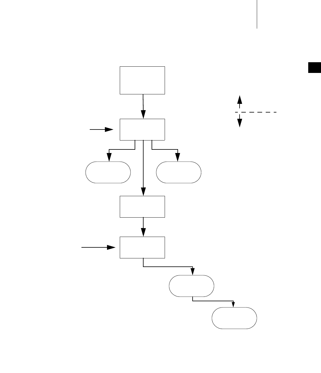
Figure 2-1 provides an overview of the boot sequence when VxWorks is booted
from an image.
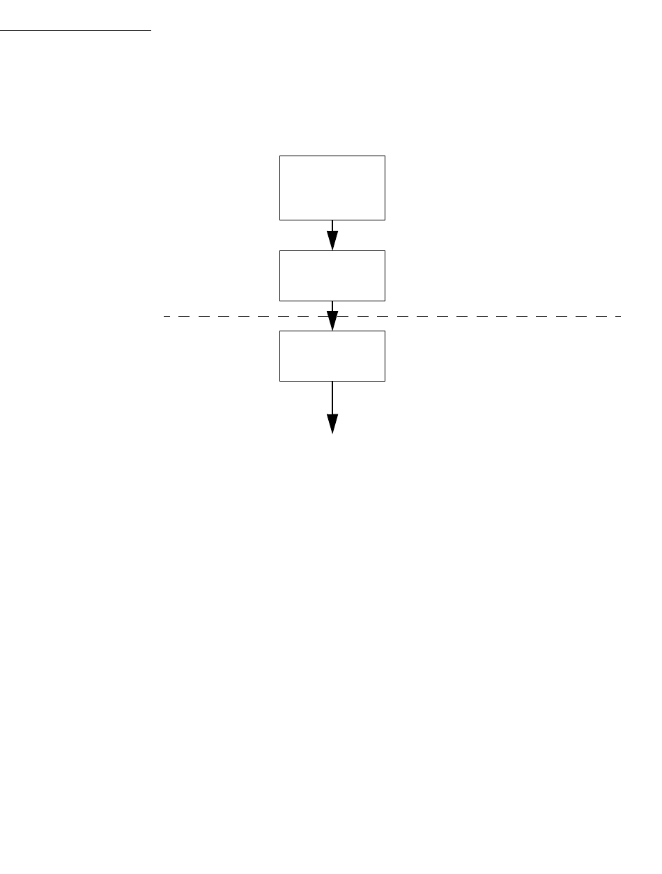
Figure 2-2 illustrates the boot sequence used when VxWorks is booted from a
ROM-based loader. Note that the boot sequence after usrInit( ) is the same as that
shown in Figure 2-1.
2 Overview of a BSP
2.2 Boot Sequence
11
2
Figure 2-1 Boot Sequence Using a VxWorks Image
sysInit
sysAlib.s
sysClkConnect
usrKernelInit
usrInit
kernelInit
usrRoot
sysHwInit
sysHwInit2
Initializes CPU.
Initializes RAM (controller).
Initializes stack, quiets CPU (disables interrupts).
boot specific
boot generic
usrInit calls usrInit calls
Provided in
target/config/all/usrConfig.c.
Performs minimal kernel initialization.
Hooks
Provided in target/config/bsp/sysLib.c.
Quiets devices (disables interrupts).
Initializes hardware.
sysHwInit0 - Provides early
BSP-specific initialization.
Configures
kernel data
structures.
Initializes and starts kernel.
Defines system memory partition.
Activates task and usrRoot.
Unlocks interrupts and sets up interrupt stack (if
supported by CPU).
Hooks
usrRoot calls
Initializes the memory partition library and MMU.
Initializes the system clock.
Activates the application and spawns a task.
Creates task tUsrRoot
VxWorks
BSP Developer's Guide, 6.6
12
2.2.2 Boot Sequence Configurations
There are several boot sequence configurations that are commonly supported. For
BSPs intended for specific applications only, at least one of the methods is
supported. General-purpose BSPs support all boot methods.
For development, the most common boot method is through the presence of a
ROM-based boot loader. The purpose of this boot loader is to load the final
VxWorks image from a remote development host (or possibly from a local file
system) and then to start running the newly downloaded image. The boot image
is a specially-crafted version of VxWorks with a boot loader as its only application.
Because this boot image is largely independent of development changes, it is
seldom necessary to re-program the flash, which saves development time. The
boot image is referred to as bootrom; the OS image that is loaded is referred to as
vxWorks. These images are described later in the document.
Figure 2-2 Boot Sequence Using a ROM Image
romStart
usrInit
Copies ROM image to RAM
Clears unused RAM
Decompresses image (if required)
Provided in
installDir/vxworks-6.x/target/config/all/usrConfig.c
Performs minimal kernel initialization
Initializes CPU
Initializes RAM (controller)
Initializes stack, quiets CPU (disable interrupts)
Provided in
installDir/vxworks-6.x/target/config/all/bootInit.c
romInit
romInit.s
...

2 Overview of a BSP
2.2 Boot Sequence
13
2
Another alternative boot method is to put the VxWorks image into flash directly.
Typically, both the core OS and the application code reside in the same image. In
this case, there is no intermediate step between loading the boot loader and
loading the application image. Also, no file system is needed to hold the final
VxWorks image file. Although this boot method can be used for development,
progress can be hindered by the need to re-program the flash often. However, this
is a very common boot mechanism in final product delivery.
Whether loading a VxWorks image from flash or loading a boot loader from flash,
there are special requirements. The processor’s reset vector causes it to start
execution of the code in flash memory. This flash-resident code can do one of
several things. It can:
■Continue running from flash (that is, fetch instructions from the flash memory
and execute them).
■Copy itself from flash to RAM and branch to an appropriate place in the RAM
copy.
■Decompress a compressed image contained in flash and put the image into
RAM, then branch to an appropriate place in the RAM copy.
The names of the different image types are determined both by the build method
used and by the behavior of the image.
An image that continues running from flash and is built from a project is normally
called vxWorks_romResident. Such an image built from the command line is
typically called one of the following image types:
■vxWorks.res_rom
■vxWorks.res_rom_res_low
■vxWorks.res_rom_nosym
■vxWorks.res_rom_nosym_res_low
■bootrom_res
■bootrom_res_high
An image that copies itself from flash to RAM and is built from a project is
normally called vxWorks_rom. Such an image built from the command line is
normally called vxWorks.st or bootrom_uncmp.
An image that decompresses itself and puts the results in RAM, and is built from
a project, is generally called vxWorks_romCompress. Such an image built from the
command line is called vxWorks.st_rom or bootrom.
If a boot loader loads a VxWorks image, whether from a local file system or from a
remote host, the image is referred to as vxWorks, regardless of how it is built.

VxWorks
BSP Developer's Guide, 6.6
14
A more detailed description of each image type is listed below. Much of this
information can be found in the file
installDir/vxworks-6.x/target/h/make/rules.bsp in your installation.
vxWorks
The primary VxWorks image that is loaded by a boot loader from a local file
system or from a remote host. If a downloaded symbol table is configured,
vxWorks requires the vxWorks.sym file.
vxWorks.sym
A symbol table that is loaded from the same file system and directory as the
vxWorks image itself.
vxWorks_rom
A VxWorks standalone ROM image programmed into flash that copies itself
to RAM for execution. This format is typically used when making an
application in ROM that does not include the shell or the symbol table. Because
these images are usually smaller, this version does not use ROM compression.
vxWorks.st
A VxWorks standalone image that is loaded by a boot loader from a local file
system or from a remote host. This VxWorks image has a symbol table already
linked in, so it does not need to load vxWorks.sym from a local file system or
over the network. This image requires a large ROM space and a large RAM
space. This image can not be run from ROM.
vxWorks.st_rom
A VxWorks standalone image programmed into flash that decompresses itself
to RAM for execution. This image includes a linked-in symbol table so that a
complete VxWorks image with shell and symbol table is put into ROM.
Because these systems tend to be large, ROM compression is used. This rule
also creates vxImage.o for use as a “core” file (to provide a symbol table) for
the target server or other host-based debugger. This image uses less ROM than
a vxWorks image and requires a large RAM space.
vxWorks.res_rom
A VxWorks image programmed into flash. This image copies the data segment
from flash into RAM, but continues to fetch instructions from flash. This image
includes a linked-in symbol table so that a complete VxWorks image with shell
and symbol table is put into ROM. This type of image uses less RAM than a
NOTE: This image format may require larger EEPROMs. The user is advised
to check the macros for ROM sizes and offsets for compatibility.

2 Overview of a BSP
2.2 Boot Sequence
15
2
vxWorks image and requires a large ROM space. In general, execution is slow
for all ROM-resident images, as compared to RAM-resident images.
vxWorks.res_rom_res_low
This image is similar to vxWorks.res_rom, but sometimes starts the data
segment in RAM closer to RAM_LOW_ADRS on some architectures.
vxWorks.res_rom_nosym
A VxWorks image programmed into flash. This image copies the data segment
from flash into RAM, but continues to fetch instructions from flash. This image
does not include a symbol table. This image uses a small amount of RAM and
requires a large ROM space. This type of image has a quick start time but
executes more slowly than a RAM image.
vxWorks.res_rom_nosym_res_low
This image is similar to vxWorks.res_rom_nosym, but sometimes starts the
data segment in RAM closer to RAM_LOW_ADRS for some architectures.
bootrom
A VxWorks image with a boot loader application that is programmed into
flash. This image decompresses itself into RAM for execution. This image
requires a minimal amount of ROM space and a large RAM space.
bootrom_uncmp
A VxWorks image with a boot loader application that is programmed into
flash. This image copies itself into RAM for execution. This image requires a
large amount of both RAM and ROM but executes quickly.
bootrom_res
A VxWorks image with a boot loader application that is programmed into
flash. This image copies its data segment into RAM for execution, but
continues fetching instructions from flash. This image requires a large ROM
space and little RAM space.
bootrom_res_high
A VxWorks image with a boot loader application that is programmed into
flash. This image copies its data segment into RAM for execution, but
continues fetching instructions from flash. This image loads the VxWorks
image into a higher location in RAM.
In the information presented above, references are made to bootrom, which is a
VxWorks image configured with a boot loader as its application. While this is
typically how the image is loaded during development, and in released products
as well, it is also possible for VxWorks to be loaded by an external agent of some
kind. For example, the image can be loaded by a boot loader not based on
VxWorks, such as a ROM monitor, or the image can be loaded directly into RAM

VxWorks
BSP Developer's Guide, 6.6
16
by a hardware debugger such as the Wind River ICE SX. For more information, see
2.4 The Development Environment, p.46. Also consult the documents listed in
1. Introduction.
2.2.3 Architecture Considerations
The VxWorks BSP design was developed to be architecture-independent.
However, many architectures and boards have special requirements. This section
briefly discusses some of these special considerations. This discussion is not
intended to be complete or comprehensive, but is intended to give an idea of the
kinds of customizations that may affect a BSP port.
The MIPS processor uses a ModeIn input pin to set 256 bits of initialization
information. This information is stored in non-volatile memory, usually
somewhere other than on the processor chip. Board designers have the option of
providing this information in a special part of ROM or NVRAM dedicated to this
purpose. However, they might also design the board to gate this information from
the boot flash. If this is the case, the flash image must reserve 32 bytes at the
beginning of the image, initialized as required by the CPU.
The Intel i960 processor has a similar requirement called the initial boot record
(IBR). However, for the i960, instead of just 256 configuration bits, the IBR contains
an exhaustive table that defines memory regions, interrupt table information,
exception handling information, and other items. This IBR must be at a fixed
location, in much the way that the initial program counter is set to a fixed location
on other processors, and the BSP must know how to handle this situation.
The most common memory configuration is for RAM to be located at addresses
beginning with 0, and for flash to be addressed in regions of upper memory.
However, on some architectures and for some types of applications, it is customary
to design the board so that flash is located at address 0 and RAM is in upper
memory. In addition, many processors locate their interrupt vectors at address 0 by
default. For boards designed in such a way that the interrupt vectors are located in
flash, there are two requirements. First, a set of default interrupt vectors must be
NOTE: The architectures discussed in this section are examples only. Your
VxWorks installation may not include support for all architectures described here.
For a list of supported architectures, see the Wind River Online Support Web site
or your product’s release notes. In addition, architectures not discussed in this
section may have special BSP requirements as well. For more information
regarding your target architecture, see the appropriate VxWorks Architecture
Supplement.

2 Overview of a BSP
2.2 Boot Sequence
17
2
located at the beginning of the flash image. Second, some mechanism must be
made available for the BSP to change the contents of the vectors when VxWorks
boots.
Some processors allow both big- and little-endian configurations. Typically, a BSP
supports only one byte order type. If both configurations are supported, a second
BSP is typically created and named with _le or _be suffix. For example, the
ixp1200eb BSP is configured for little-endian mode and the ixp1200eb_be BSP is
configured for big-endian mode. In this situation, the boot ROMs cannot typically
boot images from the other byte order.
2.2.4 Detailed Boot Sequence
The following is a step-by-step description of a generic boot sequence.
Step 1: Execute romInit( )
At power-up (cold start), the processor begins execution at the romInit( ) entry
point, located in romInit.s. For resets (warm starts), the processor begins execution
at romInit( ) plus a small offset (see sysToMonitor( ) in
installDir/vxworks-6.x/target/config/bspname/sysLib.c). The romInit( ) routine
must be written in assembly language.
The purpose of this routine is to initialize the CPU and some portion of memory. It
does the absolute minimum amount of initialization—that is, the initialization of
essential hardware only—before jumping to romStart( ). If romInit( ) is working
correctly, the memory from LOCAL_MEM_LOCAL_ADRS through
(LOCAL_MEM_LOCAL_ADRS + LOCAL_MEM_SIZE) should be readable and
writable. If this is not the case, romInit( ) is not working properly.
In addition to initializing memory as described above, the romInit( ) routine must
also disable interrupts and clear caches. romInit( ) then configures the boot type
(cold or warm) to be a subroutine argument and branches to romStart( ) in
bootInit.c. For more information on configuring the boot type, see 2.3.7 Hardware
Considerations, p.45.
romInit( ) must do only as much device setup as is required to start executing C
code. Hardware initialization is the responsibility of the sysHwInit( ) routine in
installDir/vxworks-6.x/target/config/sysLib.c, which is called later during the boot
sequence.

VxWorks
BSP Developer's Guide, 6.6
18
Step 2: Execute romStart( )
The purpose of the romStart( ) routine is to move all further bootstrap code from
ROM into RAM and then, if necessary, jump to the VxWorks image. Because this
implementation depends only on the CPU architecture, the romStart( ) routine is
provided by Wind River and is located in the file bootInit.c. Typically, romStart( )
jumps to the usrInit( ) routine in RAM.
The required execution steps are as follows:
1. Copy the data segment from flash to ROM. Depending on the image type, you
may also need to copy the text segment. If necessary, decompress the data
during the copy.
2. Clear unused RAM.
3. The romStart( ) routine then jumps to the RAM entry point, sysInit( ), which
is located in sysALib.s. The boot type (cold or warm) is passed as an argument
to sysInit( ).
Step 3: Execute sysInit( )
The sysInit( ) routine is the RAM entry point. sysInit( )—which should be the first
routine defined in sysALib.s—invalidates caches if applicable, initializes the
system interrupt tables with default stubs, initializes the system fault tables with
default stubs, and initializes all processor registers to known default values. The
routine also enables tracing, clears all pending interrupts, and finally invokes
usrInit( ) with the argument bootType.
This routine must duplicate much of the hardware initialization done by romInit( )
in order to set the run-time state rather than the boot state. Keep in mind that the
board may have been booted using a ROM monitor or hardware debugger. In this
case, the VxWorks boot ROM code, where romInit( ) is located, is not executed and
VxWorks system initialization is not performed. Therefore, failure to duplicate the
initialization code from romInit( ) may result in BSP failure.
Step 4: Execute usrInit( )
The purpose of the usrInit( ) routine is to completely initialize the CPU and shut
down any other hardware, thus preparing the way for the kernel to initialize and
start itself. This routine is located in usrConfig.c but calls routines in several other
files, some of which you must provide and some of which are provided by Wind
River. Normally, it is not necessary to modify the usrInit( ) routine provided by
Wind River. However, the sysHwInit( ) routine that must be called from usrInit( )
typically does require modification. The sysHwInit( ) routine ensures that the

2 Overview of a BSP
2.2 Boot Sequence
19
2
board-dependent hardware is quiescent. sysHwInit( ) is provided in the reference
BSP or template and is located in sysLib.c.
The usrInit( ) routine (in usrConfig.c) saves information about the boot type,
handles all initialization that must be performed before the kernel is actually
started, and then starts the kernel execution. It is the first C code to run in VxWorks.
This routine is invoked in supervisor mode with all hardware interrupts locked
out.
Many facilities cannot be invoked from this routine. There is no task context yet—
that is, no task control block (TCB) and no thread stack— therefore, facilities that
require a task context cannot be invoked. This includes any facility that can cause
the caller to be preempted (such as semaphores) or any facility that itself uses a
facility of this type, such as printf( ). Instead, the usrInit( ) routine does only what
is necessary to create the initial thread, usrRoot( ). usrRoot( ) then completes the
startup.
The initialization operations performed in usrInit( ) include the following:
■Initializing cache.
The code at the beginning of usrInit( ) initializes the caches, sets the mode of
the caches, and puts the caches in a safe state. At the end of usrInit( ), the
instruction and data caches are enabled by default.
■Zeroing out the system BSS segment.
C language specifies that all uninitialized variables (stored in bss) must have
initial values of 0. Because usrInit( ) is the first C code to execute, it clears the
section of memory containing bss.
■Initializing interrupt vectors.
The exception vectors must be initialized before enabling interrupts and
starting the kernel. First, intVecBaseSet( ) is called to establish the vector table
base address.
After intVecBaseSet( ) is called, the routine excVecInit( ) initializes all
exception vectors to default handlers. These handlers safely trap and report
exceptions caused by program errors or unexpected hardware interrupts.
NOTE: The intVecBaseSet( ) routine is not called first on all architectures. For
more information, see the appropriate VxWorks Architecture Supplement.

VxWorks
BSP Developer's Guide, 6.6
20
■Initializing system hardware to a quiescent state.
Calling the system-dependent routine sysHwInit( ) initializes the system
hardware. Initialization mainly consists of resetting and disabling hardware
devices. Otherwise, when the kernel is started and interrupts are enabled,
these devices can cause unexpected interrupts.
In VxWorks, ISRs (for I/O devices, system clocks, and so on) are not connected
to their interrupt vectors until system initialization is completed by the
usrRoot( ) task. This is a requirement because the memory pool is not yet
initialized. You must not connect an interrupt handler to an interrupt during
the sysHwInit( ) call; doing so requires memory allocation, which is not
available at this time. Most interrupt connection occurs later in the
sysHwInit2( ) routine located in sysLib.c.
■Calling kernelInit( ).
The VxWorks libraries contain the code for kernelInit( ). Therefore, it is not
normally available to BSP developers in source form. The kernelInit( ) routine
initiates the multitasking environment and never returns. It takes the
following parameters:
– address of the routine to be spawned as the root task, typically usrRoot( )
–stack size
– start of usable memory; that is, the memory after the main text, data, and
bss segments of the VxWorks image. All memory after this area is allocated
to the system memory pool, which is managed by memPartLib. All cached
dynamic allocations are derived from this memory pool.
– top of cached memory as indicated by sysMemTop( )
– interrupt stack size. The interrupt stack corresponds to the largest amount
of stack space that can be used by any interrupt-level routine that may be
called, plus a safety margin for the nesting of interrupts.
– interrupt lockout level. For architectures that have a level concept, it is the
maximum level. For architectures that do not have a level concept, it is a
mask to disable interrupts. For more details, see the appropriate VxWorks
Architecture Supplement.
NOTE: Ensure that all interrupts are disabled. A typical problem during BSP
development is that an interrupt is not correctly disabled in sysHwInit( ).
When this happens, the system can hang once interrupts are enabled in
usrInit( ) and it can be difficult to determine the cause of the problem.

2 Overview of a BSP
2.2 Boot Sequence
21
2
Step 5: Execute kernelInit( )
The kernelInit( ) routine is provided by Wind River in a VxWorks library archive
file. The purpose of this routine is to get the kernel up and running so that all
further initialization can be done as a task running under the kernel. The name of
this task is tRootTask, and the routine it executes is typically usrRoot( ).
The kernelInit( ) routine calls intLockLevelSet( ), disables round-robin
scheduling mode, and creates an interrupt stack (if supported by the architecture).
The routine then creates a root stack and a task control block (TCB) from the top
of the memory pool, spawns the root thread usrRoot( ), and terminates the
usrInit( ) thread of execution. At this time, interrupts are enabled. It is critical that
all interrupt sources be disabled by usrInit( ), and that all pending interrupts be
cleared. Failure to do so causes system failure as described in Creating Additional
Diagnostic Routines, p.67.
Step 6: Execute usrRoot( ) as a task
The purpose of the usrRoot( ) routine is to complete the initialization of the kernel
and all hardware, then launch any application code. This routine is supplied by
Wind River in the usrConfig.c file, and the original copy should not be changed.
During development, usrConfig.c is often temporarily copied to the BSP directory,
and debugging changes are made to the temporary copy. usrConfig.c is also
configurable with the macros defined in config.h.
The usrRoot( ) routine calls the memInit( ) routine. Optionally, usrRoot( ) can call
the memShowInit( ) and usrMmuInit( ) routines.
Once the system is multitasking, the BSP calls its first routine, sysClkConnect( ).
sysClkConnect( ) immediately calls the sysHwInit2( ) routine. sysHwInit2( ) is
responsible for any board initialization not completed in sysHwInit( ), such as the
connection of interrupt sources using intConnect( ).
Next, the usrRoot( ) routine continues the clock initialization. It sets the default
clock rate to the value of the macro SYS_CLK_RATE, typically 60 Hz. usrRoot( )
then enables the system clock with a call to sysClkEnable( ).
Once the clock is initialized and running, several kernel modules, such as
selectLib, the I/O subsystem, and the console, are initialized. For details, see the
NOTE: Do not use a custom version of usrConfig.c in your final BSP.
NOTE: The system clock can be dynamically changed from the shell or from an
application. However, facilities that take a “snapshot” of the clock rate (for
example, spyLib) can be broken by an unexpected rate change.

VxWorks
BSP Developer's Guide, 6.6
22
source code in usrConfig.c as well as the macros defined in configAll.h and
config.h.
If INCLUDE_WDB is defined, wdbConfig( ) in
installDir/vxworks-6.x/target/src/config/usrWdb.c is called. This routine initializes
the agent’s communication interface, and then starts the debug agent. For
information on configuring the agent, see the VxWorks Kernel Programmer’s Guide:
Targ et Too ls . The debug agent is the portion of VxWorks that connects to and serves
the Workbench tools such as the shell and the debugger.
If the INCLUDE_USR_APPL macro is defined, the default usrRoot( ) code executes
the USER_APPL_INIT macro. This macro allows you to start your application
automatically at boot time. The BSP assumes that the USER_APPL_INIT macro is a
valid C statement. For more information on USER_APPL_INIT, see the appropriate
VxWorks programmer’s guide.
2.3 Components of a BSP
The BSP directory contains source files, header files, a makefile (Makefile), one or
more documentation files (target.nr or target.ref), and possibly other files such as
derived files and object modules distributed in object format only.
From the BSP directory, other derivative files may be generated; for example, there
may be files generated for a project. Some derived files are not put into the BSP
directory itself. These include the WPJ project file, additional source and header
files, a custom usrAppInit.c file, another makefile for use with the project facility,
and directories containing object modules.
In addition to the BSP directory, there are several other directories that contain files
related to the BSP.
The installDir/vxworks-6.x/target/config/all directory contains some source and
header files that are used by the BSPs for default configuration. The files in this
directory should never be changed. If changes to a file are necessary, copy the file
to the BSP directory and make changes to the local copy.

2 Overview of a BSP
2.3 Components of a BSP
23
2
The makefile provides a mechanism that allows you to use the local copy instead
of the common version. The following macros designate a private copy of the
related files:
For example, to use a private version of usrConfig.c, set the macro USRCONFIG to
usrConfig.c in Makefile as follows:
USRCONFIG = usrConfig.c
2.3.1 Source and Include Files
BSP routines are contained in a number of C and assembly files that you may need
to modify or create. These routines are located in a relatively small number of
source files. This section provides a list of these source files as well as a detailed
description of each file. Each file is also documented extensively in the reference
and template BSPs (see the code comments in each file).
The following files, in installDir/vxworks-6.x/target/config/bspname, may need to
be created or modified:
USRCONFIG usrConfig.c
BOOTINIT bootInit.c
DATASEGPAD dataSegPad.c
README documentation file
Makefile makefile for building the BSP
config.h header file for configuring the OS
bspname.h header file for non-configurable definitions
romInit.s includes the romInit( ) routine and any subroutines used by
romInit( ).
sysALib.s contains assembly routines that are not part of romInit( )
(optional).
sysLib.c contains the sysHwInit( ) routine and additional C language
routines specific to the target hardware.

VxWorks
BSP Developer's Guide, 6.6
24
The following files, located in installDir/vxworks-6.x/target/config/all, may be
copied to the BSP directory and modified during BSP development by adding
diagnostic statements. Typically, the files used in the final version of the BSP are
not modified.
Typically, the following file, in installDir/vxworks-6.x/target/src/config, is not
modified:
README
Use this plain-text file to document the history of the BSP. That is, include
information on when you wrote the BSP, any modifications made, which BSP was
used as a template, what general changes you made, and so on.
sysDev.c If used, this file contains the device driver interface to the physical
hardware device, Dev.
Note that the actual device driver files are kept in
installDir/vxworks-6.x/target/src/hwif/drvType (VxBus model
device drivers) and installDir/vxworks-6.x/target/src/drv/drvType
(legacy model device drivers). For example,
installDir/vxworks-6.x/target/src/drv/sio contains serial drivers.
There may be multiple sysDev.c files.
target.ref BSP documentation file (uses the apigen markup language). For
more information on BSP documentation files, see B. Implementing
Documentation Guidelines, or the reference entry for apigen.
(VxWorks 5.5 users can consult the reference entry for refgen.)
target.nr Older BSP documentation file (uses nroff markup language). This
file is superseded by the target.ref file but is still used in some
older BSPs. For more information on BSP documentation files, see
B. Implementing Documentation Guidelines.
configAll.h global header file for configuring the OS
bootInit.c contains the romStart( ) routine
usrConfig.c contains the usrInit( ) and usrRoot( ) routines
usrKernel.c This file contains all the #ifdefs that are controlled by makefile
macros to configure the kernel.

2 Overview of a BSP
2.3 Components of a BSP
25
2
Makefile
This file controls the build of the VxWorks image. You must set several variables
within this makefile. The required variables are listed and described in the
2.3.5 Required Macros, p.42.
config.h
This header file contains all #include and #define macros specific to configuring
the CPU and board architectures. It also contains any necessary overrides to the
macro definitions in configAll.h, which you must include using #include. You
must also include the bspname.h header in this file.
bspname.h
This header file contains all the header information for the BSP that is not related
to OS configuration. The information in this header file is required under all
configurations of VxWorks using this BSP. This file includes any headers for device
drivers.
Use bspname.h to set all non-optional, board-specific information, as defined in this
file; including definitions for the serial interface, timer, and I/O devices.
This file is intended for constant information that is not subject to user
configuration. If any macros or values defined in this file can be changed to
customize this system, define those macros or values in config.h instead.
When developing your BSP, it is helpful to use a sample header file as a starting
point. In most cases, the sample file requires minimal modification because most
constant names, basic device addresses, and so on are already defined in the
sample file. Define the following in bspname.h:
interrupt vectors and levels
Define all interrupt vectors and levels that are dictated by hardware in
bspname.h.
I/O device addresses
Define all I/O addresses fixed by hardware in bspname.h.
NOTE: In general, use the config.h file to define configurable values and the
bspname.h file to define values fixed in hardware.

VxWorks
BSP Developer's Guide, 6.6
26
meaning of device register bits
For on-board control registers, define a macro value for each bit or group of
bits in each register. Place such macro definitions in bspname.h if there is no
better location (such as a device-specific header file) for them.
system and auxiliary clock parameters
Define maximum and minimum rates.
sysALib.s
This file contains the RAM image’s entry point, _sysInit( ). _sysInit( ) performs
any required hardware-specific initialization before jumping to usrInit( ) in
usrConfig.c.
Any additional utility routines that must be written in assembly language and are
required during normal system operation are also contained in sysALib.s.
romInit.s
This assembly file contains the romInit( ) routine, which is the entry point for
bootstrapping, plus any romInit( ) subroutines. The romInit( ) routine must be the
first routine in the text segment of romInit.s.
At power-up (cold start) the processor begins execution at romInit( ). For warm
starts, the processor begins execution at romInit( ) plus a small offset (see
sysToMonitor( ) in sysLib.c). Most hardware and device initialization is
performed later in the boot sequence by sysHwInit( ), which is located in sysLib.c.
The job of romInit( ) is to perform the minimal setup needed to transfer control to
romStart( ), located in installDir/vxworks-6.x/target/config/all/bootInit.c. The
minimal setup includes:
■Initializing the processor (this code is specific to the processor but not the
board, and thus can be copied from a reference BSP):
– mask processor interrupts
– set the initial stack pointer to STACK_ADRS (defined in configAll.h)
– disable processor caches
NOTE: It is advisable to include macros describing all available bits, or groups of
bits in each control register, even if those bits are not used by the BSP.

2 Overview of a BSP
2.3 Components of a BSP
27
2
■Initializing access to target DRAM as needed for the following (this code is
board-specific):
– wait states
–refresh rate
– chip-selects
– disabling secondary (L2) caches (if needed)
At the end of the initialization sequence, romInit( ) jumps to romStart( ) in
bootInit.c, passing the start type. The start type is BOOT_COLD for a cold boot, or
the parameter passed from sysToMonitor( ) on a warm boot.
For more information, see romInit.s in a reference BSP or the template romInit.s
file in the template BSP. Also see 2.3.7 Hardware Considerations, p.45.
sysLib.c
The sysLib.c file contains the routines that directly or indirectly initialize all
hardware device drivers. The principal routines for initializing the hardware
drivers are sysHwInit( ) and sysHwInit2( ), but additional driver initialization
routines are called by usrRoot( ), such as sysClkConnect( ), which calls
sysHwInit2( ). These routines are described in 2.3.4 Required Routines, p.35. Also
see the source code in your reference BSP or the template BSP.
While sysLib.c is the largest BSP file, in the early phases of BSP development it is
advisable to implement only the basics, including sysModel( ), sysBspRev( ),
sysHwInit( ), sysHwInit2( ), and sysMemTop( ).
The file sysLib.c also includes the following NVRAM stub drivers during initial
development:
#include "mem/nullNvram.c"
#include "vme/nullVme.c"
Additional information about NVRAM support is provided in 3.3.4 Enabling
NVRAM, p.80.
The sysHwInit( ) routine is the heart of sysLib.c, and most of the initial work is
done here. sysHwInit( ) is the routine that resets all devices to a quiescent state so
that they do not generate interrupts later on when interrupts are enabled.

VxWorks
BSP Developer's Guide, 6.6
28
target.ref or target.nr
This file describes the BSP, and is used to generate automatic online documentation
in HTML format. To format the documentation as HTML, type make man in the
BSP directory.
For more information on updating and using this file, see 3.3.8 Updating
BSP-Specific Documentation, p.105, and B. Implementing Documentation Guidelines.
board.jpg
This optional file contains a JPEG image of the target system board. You may wish
to label the images to show the serial connector, power connector, and Ethernet
connector.
sysDev.c
Legacy drivers are split between the core driver and a BSP support file called
sysDev.c. If used, this file contains the device driver interface to the physical
hardware device, dev. Note that for legacy device drivers, the core device driver
files are kept in installDir/vxworks-6.2/target/src/drv/drvType; for example
installDir/vxworks-6.x/target/src/drv/sio contains legacy serial drivers. There may
be multiple sysDev.c files.
Each device driver available for target hardware has its own sysDev.c file, where
Dev is a short identifier for the target hardware. For example, sysNet.c and
sysSerial.c would identify network interface and serial port drivers, respectively.
Some device drivers are optional and the standard drivers provided in
installDir/vxworks-6.x/target/src/drv can be used. In some cases, custom device
drivers must be created for a BSP, and these custom drivers should reside in the
NOTE: When hardware features are missing, it is usually safe to code an empty
stub in sysLib.c. If any return value is required, the stub can return ERROR or
NULL, whichever is appropriate.
NOTE: VxBus drivers do not require sysDev.c files. (For more information on
VxBus, see the VxWorks Device Driver Developer’s Guide, Volume 1: Fundamentals of
Writing Device Drivers.)

2 Overview of a BSP
2.3 Components of a BSP
29
2
BSP directory (although this is not a requirement). Device driver files are detailed
in the following sections of this guide:
■3.2.10 Minimum Required Drivers, p.75
■3.2.11 Serial Drivers, p.76
■3.3.9 Providing Additional Optional Device Support, p.106
Additional information on device drivers can be found in the VxWorks Device
Driver Developer’s Guide.
The sysDev.c files are normally included in sysLib.c with a #include rather than
compiled separately. This allows hardware drivers to be shared between BSPs
without adding complexity to the makefiles.
hwconf.c
The hwconf.c file contains hardware configuration information used by VxBus.
This information is kept in tables, and is read by VxBus during configuration.
There is no executable code present in this file. For more information on VxBus, see
the VxWorks Device Driver Developer’s Guide, Volume 1: Fundamentals of Writing
Device Drivers.
configAll.h
This file contains the default OS configuration for all BSPs, and should only be
changed under extreme circumstances. Changing this file makes your BSP
incompatible with all default VxWorks installations. Any make variable defined in
this file can be overridden in config.h.
NOTE: In some cases, the sysDev.c file contains the actual device driver instead of
an interface between the driver and the OS. This is considered incorrect design.
The preferred method is to have the driver contained in a separate file, devType.c
(for example, acmeSio.c) and the interface module contained in the sysDev.c file
(for example, sysAcmeSio.c). This method allows for better code reuse.
!CAUTION: Changing configAll.h can impact other VxWorks users sharing your
VxWorks installation.

VxWorks
BSP Developer's Guide, 6.6
30
bootInit.c
The bootInit.c file contains romStart( ), which is the first C routine to execute
during the VxWorks boot process. This routine is architecture-independent and
should not require changing.
The routine romStart( ) is essentially a loader. It performs the necessary
decompression and relocation for the ROM images. First, it copies the text and data
segments from ROM to RAM. Then, it clears those parts of the main RAM not
otherwise used. Finally, romStart( ) decompresses the compressed portion of the
image. Different configuration options can modify how these operations are
performed.
usrConfig.c
The usrConfig.c file contains the usrInit( ) and usrRoot( ) routines. When
usrRoot( ) completes, the VxWorks boot is complete. Both usrInit( ) and usrRoot( )
are architecture-independent, and thus should not require changing.
During BSP development, the usrConfig.c file is usually copied into the BSP
directory and modified to allow the user to control what hardware is initialized
(this is achieved by removing portions of usrRoot( ) using #if FALSE/#endif
pairs). The temporary copy must be discarded when the BSP is complete.
Therefore, changes are limited to debug code only.
2.3.2 Derived Files
The most obvious files derived from the BSP files are the VxWorks images. There
may be multiple copies of VxWorks images present in a BSP directory, each
representing a different build type. For example, it is possible for the BSP directory
to contain bootrom, bootrom_uncmp, vxWorks (and its vxWorks.sym file),
vxWorks.st, and vxWorks.res_rom as well as several other images all at the same
time.
NOTE: The bootInit.c file is shared by all BSPs. Ensure that changes made to
bootInit.c do not impact the functionality of other BSPs.
NOTE: The usrConfig.c file is shared by all BSPs. Because of this, you must ensure
that changes made to usrConfig.c do not impact the functionality of other BSPs.

2 Overview of a BSP
2.3 Components of a BSP
31
2
In addition, building the source files in the BSP directory generates object files.
There is not a one-to-one correspondence between source files and object files. As
mentioned in sysLib.c, p.27, the sysLib.c file uses the #include compiler
preprocessor directive to include other source files, especially the sysDev.c files.
For example, in the wrSbc8260 BSP, there is a file called sysIOPort.c that contains
interface code for the PowerPC 8260 I/O port drivers. The #include is as follows:
#include "sysIOPort.c"
This means that the BSP contains a source file sysIOPort.c that does not have a
corresponding object module. Instead of a separate object module, that object code
is included in sysLib.o.
Another source of derived files is the target.ref (or target.nr) documentation file in
the BSP directory. This file is maintained in an unprocessed form that is difficult to
read. To process the target.ref file, issue a make man command in the BSP
directory. This command results in a new HTML file that is suitable for online
viewing. For more information on the HTML output or the target.ref file, see
B. Implementing Documentation Guidelines.
Other objects derived from files in the BSP directory are related to the project
facility. Each time a bootable project is created from a BSP directory, a projName.wpj
file is created. A project also contains several derived source and header files
including a makefile for use with the project facility, a prjObjs.lst file containing a
list of all the object modules used for the build, and directories containing the
object modules and VxWorks images themselves. Note that although these objects
are derived from information in the BSP directory, the objects themselves are not
located in the BSP directory.
2.3.3 Required Data Variables
You must declare and initialize the following data variables in your BSP:
sysPhysMemDesc[ ] determines physical memory layout
sysPhysMemDescNumEnt number of entries in sysPhysMemDesc[ ]
sysBootLine address of boot line
sysExcMsg catastrophic message area
sysFlags boot flags

VxWorks
BSP Developer's Guide, 6.6
32
sysPhysMemDesc[ ]
The sysPhysMemDesc[ ] array holds descriptions of different memory ranges on
the board.
PHYS_MEM_DESC sysPhysMemDesc[ ]
The array is used by several VxWorks libraries, including the memory
management subsystem. This array must be initialized by the BSP. Typically, it is
initialized statically during compile time, but it may also be initialized
dynamically early in the boot process.
Values for statically defined sysPhysMemDesc[ ] entries are assigned using
descriptive macro names.
The kinds of memory described by sysPhysMemDesc[ ] entries include system
RAM, flash, or ROM, memory mapped processor registers, board registers,
memory mapped device registers including PCI memory space, vector table, static
RAM, or anything else that uses a memory mapped address range.
The fields included in the PHYS_MEM_DESC structure are, in order:
virtualAddr
the virtual address of the beginning of the memory region
physicalAddr
the physical address of the beginning of the memory region
len
the length, in bytes, of the memory region
initialStateMask
a mask for the initial VM state
initialState
the initial state to which the memory management library should set the
memory
hcfDeviceList[ ] Static hardware configuration information.
hcfDeviceNum Number of devices in hcfDeviceList[ ].
devUnitCfgData[ ] Device configuration information.

2 Overview of a BSP
2.3 Components of a BSP
33
2
The masks used in initalStateMask are defined in vmLib.h:
VM_STATE_MASK_VALID
VM_STATE_MASK_WRITABLE
VM_STATE_MASK_CACHEABLE
VM_STATE_MASK_MEM_COHERENCY
VM_STATE_MASK_GUARDED
Additional mask values may be available on some architectures. Check
vmLib.h and the appropriate architecture supplement for more information.
The following state values are available:
VM_STATE_VALID
VM_STATE_WRITABLE
VM_STATE_CACHEABLE
VM_STATE_MEM_COHERENCY
VM_STATE_GUARDED
Additional state values may be available on some architectures. Check
vmLib.h and the appropriate architecture supplement for more information.
sysPhysMemDescNumEnt
The sysPhysMemDescNumEnt variable contains the number of entries in
sysPhysMemDesc[ ].
int sysPhysMemDescNumEnt
This variable is typically initialized statically at compile time.
sysBootLine
The sysBootLine string pointer points to the boot line that is configured for use
when booting the system.
char *sysBootLine
The boot information is parsed using bootLineCrack( ). It is typically set to the
value BOOT_LINE_ADRS, and points to the boot line information in NVRAM.
NOTE: VxWorks is a 32-bit OS, so it supports 32-bit virtual addressing.
However, on hardware that provides an address space larger than 32 bits,
VxWorks supports a physical addressing space of up to 64 bits.

VxWorks
BSP Developer's Guide, 6.6
34
sysExcMsg
The value of sysExcMsg should be initialized at compile time to EXC_MSG_ADRS,
which is set to a default value in configAll.h.
char *sysExcMsg
When there is a serious or catastrophic problem during the boot process, the
system puts error messages at the location specified by sysExcMsg. This memory
can then be examined from an external agent such as the bootrom image, or with
an on-chip debugger.
sysFlags
The sysFlags variable holds the boot flags, which control factors such as whether
to perform an autoboot or whether to use TFTP as the boot device.
int sysFlags; /* boot flags */
This variable is used extensively by bootrom. The value of sysFlags is initialized
in usrConfig.c.
hcfDeviceList[ ]
The hcfDeviceList[ ] array holds information about static hardware configuration.
Each record contains the name of the device, a counter for the device (in other
words, a unit number), the type of bus on which the device resides, which is
typically PLB (using the preprocessor macro VXB_BUSID_PLB), a pointer to
another table containing configuration data specific to the device, and the number
of entries in the configuration data table.
hcfDeviceNum
The hcfDeviceNum contains a count of the number of devices represented in
hcfDeviceList[ ].
devUnitCfgData[ ]
The devUnitCfgData[ ] tables hold configuration information specific to a single
device. These data are kept in records containing three fields: the name of the

2 Overview of a BSP
2.3 Components of a BSP
35
2
configuration datum, the data type of the configuration datum (which can be
integer, string, or address/pointer), and the value.
2.3.4 Required Routines
The following routines must be present in your BSP. Failure to provide any of these
routines results in unresolved references at link time.
At the beginning of the development process, the required routines are very
simple. In most cases, these routines are expanded over the course of the
development effort. The following pages describe the initial code for each required
routine, and the file in which it is usually included.
sysBspRev( ) returns the BSP version and revision number
sysClkConnect( ) connects a routine to the system clock interrupt
sysClkDisable( ) turns off system clock interrupts
sysClkEnable( ) turns on system clock interrupts
sysClkInt( ) handles system clock interrupts
sysClkRateGet( ) gets the system clock rate
sysClkRateSet( ) sets the system clock rate
sysHwInit( ) initializes the system hardware to a quiescent state
sysHwInit2( ) initializes and configures additional system hardware
sysMemTop( ) gets the address of the top of physical memory
sysModel( ) returns the model name of the target system board
sysNvRamGet( ) gets the contents of non-volatile RAM
sysNvRamSet( ) sets the contents of non-volatile RAM
sysSerialChanGet( ) gets the
SIO_CHAN device associated with a serial channel
sysSerialHwInit( ) initializes the BSP serial device(s) to a quiescent state
sysSerialHwInit2( ) connects BSP serial device interrupts
sysToMonitor( ) transfers control to the ROM monitor

VxWorks
BSP Developer's Guide, 6.6
36
sysBspRev( )
The routine sysBspRev( ) is identical in all BSPs. This routine can be taken directly
from the reference or template BSP and does not require modification.
Timer Driver Routines
Timer driver routines include the following:
There are several timer drivers provided by Wind River. Files for these drivers are
located in the installDir/vxworks-6.x/target/src/drv/timer directory. If one of the
existing timer drivers works for your target board, your sysLib.c file can simply
include the appropriate file from the timer directory. For example, the MIPS R4000
processor includes an on-chip timer. This timer driver is provided in
installDir/vxworks-6.x/target/src/drv/timer/mipsR4kTimer.c. If your board uses
this processor, your sysLib.c file can include the driver as follows:
#include "timer/mipsR4kTimer.c" /* system timer */
In some cases, you may need to include both a header file from
installDir/vxworks-6.x/target/h/drv/timer and a source file from
installDir/vxworks-6.x/target/src/drv/timer. Check the
installDir/vxworks-6.x/target/h/drv/timer directory to see whether a header file for
your driver is available.
If a standard timer driver is not provided for your target hardware, you may be
able to copy an existing timer driver file to the BSP directory and make minor
modifications. If you do this, it is wise to change the file name and routine names
to avoid confusion. For example, some BSPs for ARM processors started with the
ambaTimer.c file and renamed it as the ixm1200Timer.c file. Be sure to document
the name of the original driver in the source file.
In rare situations, you may need to create a custom sysTimer.c file. If this is the case
for your BSP, you can copy routine prototypes for the sysClk*() routines from any
of the existing timer drivers in installDir/vxworks-6.x/target/src/drv/timer.
sysClkConnect( )
sysClkDisable( )
sysClkEnable( )
sysClkInt( )
sysClkRateGet( )
sysClkRateSet( )

2 Overview of a BSP
2.3 Components of a BSP
37
2
sysMemTop( )
The sysMemTop( ) routine returns the address of the top of VxWorks memory.
During early BSP development, the sysMemTop( ) routine in sysLib.c simply
returns a constant value based on LOCAL_MEM_LOCAL_ADRS,
LOCAL_MEM_SIZE, PM_RESERVED_MEM (VxWorks 6.x only), and
USER_RESERVED_MEM.
In most implementations, sysMemTop( ) calls sysPhysMemTop( ) to obtain the
address at the top of physical memory (for more information, see
sysPhysMemTop( ), p.38). Later, during BSP cleanup, the sysPhysMemTop( )
routine can be enhanced to allow automatic memory sizing.
The following is a macro-controlled version of sysMemTop( ) that can be used by
any BSP to support fixed memory size:
/***************************************************************************
*
* sysMemTop - get the address of the top of VxWorks memory
*
* This routine returns a pointer to the first byte of memory not
* controlled or used by VxWorks.
*
* The user can reserve memory space by defining the macro USER_RESERVED_MEM
* in config.h. This routine returns the address of the reserved memory
* area. The value of USER_RESERVED_MEM is in bytes.
*
* RETURNS: The address of the top of VxWorks memory.
*/
char *sysMemTop
(
void
)
{
static char * memTop = NULL;
if ( memTop == NULL )
{
memTop = sysPhysMemTop () - USER_RESERVED_MEM;
#ifdef INCLUDE_EDR_PM
/* account for ED&R persistent memory */
memTop = memTop - PM_RESERVED_MEM;
#endif
}
return memTop ;
}

VxWorks
BSP Developer's Guide, 6.6
38
sysPhysMemTop( )
The sysPhysMemTop( ) routine in sysLib.c returns the address of the top of
physical memory. This routine is required for VxWorks 6.x BSPs and, although it is
not strictly required for VxWorks 5.5 BSPs, it is included in most. This routine can
be enhanced to allow automatic memory sizing.
/***********************************************************************
*
* sysPhysMemTop - get the address of the top of physical memory
*
* This routine returns the address of the first missing byte of memory,
* which indicates the top of memory.
*
* Normally, the user specifies the amount of physical memory with the
* macro LOCAL_MEM_SIZE in config.h. BSPs that support run-time
* memory sizing do so only if the macro LOCAL_MEM_AUTOSIZE is defined.
* If not defined, then LOCAL_MEM_SIZE is assumed to be, and must be, the
* true size of physical memory.
*
* NOTE: Do not adjust LOCAL_MEM_SIZE to reserve memory for application
* use. See sysMemTop() for more information on reserving memory.
*
* RETURNS: The address of the top of physical memory.
*
* ERRNO
*
* SEE ALSO: sysMemTop()
*/
char * sysPhysMemTop (void)
{
LOCAL char * physTop = NULL;
if (physTop == NULL)
{
physTop = (char *)(LOCAL_MEM_LOCAL_ADRS + LOCAL_MEM_SIZE);
}
return (physTop) ;
}
sysModel( )
The sysModel( ) routine in sysLib.c returns a string pointing to the model number
of the board. For simple BSPs, this routine returns a constant string. If the BSP
supports multiple board models, sysModel( ) requires a method to distinguish
between boards to determine which of the related strings to use. The following is
a simple example:

2 Overview of a BSP
2.3 Components of a BSP
39
2
/****************************************************************************
*
* sysModel - return the model name of the CPU board
*
* This routine returns the model name of the CPU board.
*
* RETURNS: A pointer to the string.
*/
char * sysModel (void)
{
return (SYS_MODEL);
}
NVRAM Routines
The sysNvRamSet( ) and sysNvRamGet( ) routines can be provided initially by
nullNvRam.c, which is included from sysLib.c. Later, during BSP cleanup, the
appropriate standard version (available in
installDir/vxworks-6.x/target/src/drv/mem) should be used or a custom version
should be created.
Hardware Initialization Routines
Hardware initialization routines include the following:
You must create these custom routines. However, during initial development,
empty stubs can be used.
When you are ready to add these routines, check the reference BSP to see how it
handles devices that are common to your board. However, you must be sure to add
code to quiesce all devices on your board, including those that are not present on
the reference board. Otherwise, you may encounter problems once interrupts are
enabled.
The cache initialization routines, including the routines to initialize L2 cache,
should be called from sysHwInit( ). The requirement is that these routines must be
called before cacheEnable( ) during the boot process. For more information, see
3.3.5 Enabling Cache and MMU Devices, p.81.
sysHwInit( )
sysHwInit2( )
sysSerialHwInit( )
sysSerialHwInit2( )

VxWorks
BSP Developer's Guide, 6.6
40
sysSerialChanGet( )
The sysSerialChanGet( ) routine in sysSerial.c returns the per-port SIO_CHAN
structure required for each serial I/O (SIO) device. For more information, see
Multi-Mode Serial (SIO) Drivers, p.111. If a fixed number of SIO devices are
supported, this routine returns a pointer to a statically allocated structure. The
following is a sample for a generic BSP supporting exactly two serial devices:
LOCAL SIO_CHAN boardSccChan1;
LOCAL SIO_CHAN boardSccChan2;
/****************************************************************************
*
* sysSerialChanGet - get the SIO_CHAN device associated with a serial channel
*
* This routine gets the SIO_CHAN device associated with a specified serial
* channel.
*
* RETURNS: A pointer to the SIO_CHAN structure for the channel, or ERROR
* if the channel is invalid.
*/
SIO_CHAN * sysSerialChanGet
(
int channel /* serial channel */
)
{
if (channel == 0)
return ((SIO_CHAN *) &boardSccChan1);
else if (channel == 1)
return ((SIO_CHAN *) &boardSccChan2);
else
return ((SIO_CHAN *) ERROR);
}
sysToMonitor( )
The sysToMonitor( ) routine in sysLib.c is called to reboot the system when ctrl+x
is pressed on the console keyboard or, on some systems, when certain processor
errors occur at interrupt level. When sysToMonitor( ) hands control over to the
boot monitor, the system must be set to a state where no interrupts occur; failure
to do this causes the reboot to fail. The following template can be used as a starting
point. However, the TO BE DONE sections must be replaced by code that performs
the stated operations.

2 Overview of a BSP
2.3 Components of a BSP
41
2
/****************************************************************************
*
* sysToMonitor - transfer control to the ROM monitor
*
* This routine transfers control to the ROM monitor. Normally, it is called
* only by reboot()--which services ^X--and bus errors at interrupt level.
* However, in some circumstances, the user may wish to introduce a
* <startType> to enable special boot ROM facilities.
*
* RETURNS: Does not return.
*/
STATUS sysToMonitor
(
int startType /* parameter passed to ROM to tell it how to boot */
)
{
/* Warm reboot address */
/* NOTE: the address to use here is processor-dependent */
FUNCPTR pRom = (FUNCPTR) (ROM_TEXT_ADRS + some offset);
/* lock interrupts */
intCpuLock();
/* disable processor-level cache */
cacheDisable(INSTRUCTION_CACHE);
cacheDisable(DATA_CACHE);
/* disable board-level cache */
/* TO BE DONE */
/* disable aux clock, if one is provided by the BSP */
/* TO BE DONE */
/* disable local devices on the board, e.g. serial devices */
/* TO BE DONE */
/* reset the serial device */
sysSerialReset();
/* set processor state to reasonable value */
/* TO BE DONE */
/* jump to bootrom entry point */
(*pRom) (startType);
/* in case we ever continue from ROM monitor */
return (OK);
}
A template for this routine is also available in the template BSP for your
architecture, and examples are available in the reference BSPs included with your
installation. However, you are encouraged to review the above template, as
functionality in the template and reference BSPs may be incomplete.

VxWorks
BSP Developer's Guide, 6.6
42
2.3.5 Required Macros
BSP macros are defined in either Makefile or config.h, with some macros defined
in both files. The following macros are required for all BSPs unless otherwise
specified:
CPU (defined in Makefile)
The target CPU, which must be the same as for the reference BSP.
CPU_VARIANT
The target CPU variant (for example, _bcm125x for MIPS Broadcom devices).
This macro is not required for all architectures. For more information, see the
VxWorks Architecture Supplement for your target processor.
TOOL (defined in Makefile)
The host tool chain (for example, diab), which must be the same as in the
reference BSP. Most BSPs support both the Wind River Compiler (diab) and
the Wind River GNU Compiler (gnu).
TGT_DIR (defined in Makefile)
The path to the target directory. The default is installDir/vxworks-6.x/target.
TARGET_DIR (defined in Makefile)
The BSP directory name.
VENDOR (defined in Makefile)
The name of the target board manufacturer.
BOARD (defined in Makefile)
The target board name.
ROM_TEXT_ADRS (defined in Makefile and config.h)
The boot ROM entry address in hexadecimal notation. For most target
systems, this is set to the beginning of the flash address area. However, there
may be some hardware configurations that use an area at the start of flash for
the reset vector. In this case, the address is offset accordingly.
The offset is typically architecture-dependent. Therefore, the low-order bytes
of this macro can be copied from a reference BSP.
ROM_LINK_ADRS (optional, defined in Makefile and config.h)
If used, this macro specifies the boot ROM link address in hexidecimal form.
For most boards, it is set to the beginning of the flash address area. If this
address is present, the linker uses it to link the boot ROM image. Otherwise,
ROM_TEXT_ADRS is used as the link address.

2 Overview of a BSP
2.3 Components of a BSP
43
2
ROM_WARM_ADRS
(optional, defined in both Makefile and config.h, or in either)
The boot ROM warm boot entry address in hexadecimal form. This is usually
a fixed offset beyond the cold boot entry point, ROM_TEXT_ADRS. The offset
is architecture-dependent, and can be obtained from the reference BSP or from
the bcopyLong( ) or copyLong( ) call in bootInit.c (located in the
installDir/vxworks-6.x/target/config/all directory). If ROM_WARM_ADRS is
defined, the code in sysToMonitor( ) does an explicit jump to
ROM_WARM_ADRS when a switch to the hardware ROM code is desired.
ROM_SIZE (defined in Makefile and config.h)
The flash area size in hexadecimal notation.
RAM_LOW_ADRS and RAM_HIGH_ADRS (defined in Makefile and config.h)
RAM_LOW_ADRS is the address at which VxWorks is loaded.
RAM_HIGH_ADRS is the destination address used when copying the boot
ROM image to RAM.
HEX_FLAGS (defined in Makefile)
Defines the architecture-specific flags for the objcopy utility that generates
S-record files.
MACH_EXTRA (defined in Makefile)
Defines any extra machine-dependent files. In early development, make this
an empty declaration.
BSP_VER_1_1 (defined in config.h)
BSP_VER_1_2 (defined in config.h)
BSP_VERSION (defined in config.h)
BSP_REV (defined in config.h)
These macros indicate the version and revision numbers for the BSP. The
version number indicates which version of VxWorks can be used with the BSP.
A value of 1.2 for BSP_VERSION indicates that the BSP is intended for use with
VxWorks 5.4 or VxWorks 5.5 (Tornado 2.x). A value of 2.0 indicates a BSP that
is intended for use with VxWorks 6.x. If BSP_VER_1_1 is defined with a value
of 1, it indicates that the BSP is backward-compatible with VxWorks 5.4
(Tornado 1.0.1).
NOTE: RAM_LOW_ADRS and RAM_HIGH_ADRS are absolute addresses,
typically chosen to be at an architecture-specific offset from the start of DRAM.
For information on the normal VxWorks memory layout, see the memory
layout diagram in the appropriate VxWorks Architecture Supplement.

VxWorks
BSP Developer's Guide, 6.6
44
These macros must be defined before the configAll.h file is included. Note that
BSP_VERSION and BSP_REV should contain strings.
LOCAL_MEM_LOCAL_ADRS (defined in config.h)
The start of the on-board memory area.
LOCAL_MEM_AUTOSIZE or LOCAL_MEM_SIZE (defined in config.h)
Only one of these two macros is defined for a given BSP.
If defined, LOCAL_MEM_SIZE defines the fixed (static) memory size.
If defined, LOCAL_MEM_AUTOSIZE indicates that the BSP determines the
actual memory size when booting, and that no static size is assumed.
ROM_BASE_ADRS (defined in config.h)
The ROM start address in hexadecimal form.
ROM_WARM_ADRS (defined in config.h)
The warm boot entry address. This is usually defined as an offset from
ROM_TEXT_ADRS.
USER_RESERVED_MEM (defined in config.h)
Size (in bytes) of the memory region reserved for application use. For more
information, see Wind River Technical Note #41. The default value is 0 for all
BSPs.
VMA_START (optional, defined in Makefile)
This macro is used for creating hex files (for example, bootrom.hex). The
default value is 0x00000000. If defined, it should be a hex address with a
leading 0x. In some BSPs, this macro is defined as follows:
VMA_START = 0x$(ROM_TEXT_ADRS)
NUM_TTY (defined in config.h)
The number of TTY ports to be configured at boot time. The default value is 2.
Some additional architecture-specific macros may also be required in the makefile.
For example, the i960 architecture must be instructed as to where to link the initial
NOTE: The BSP version and revision must be included in the BSP README file
as well as in the config.h file. The definitions in these two files must agree.
NOTE: Unless otherwise specified, the hexadecimal addresses in the macros in
Makefile must not include a leading 0x. The copies in config.h must include the
leading 0x.

2 Overview of a BSP
2.3 Components of a BSP
45
2
boot record. For architecture-specific information, see the appropriate VxWorks
Architecture Supplement and the VxWorks Hardware Considerations Guide.
2.3.6 Optional Routines
Most BSPs provide routines beyond those that are required. Typically, an auxiliary
clock and a serial port are provided. In addition, some kind of Ethernet interface is
supported. Other hardware is often made available as well. Descriptions of the
routines required to support these hardware features are included in the
3.3.9 Providing Additional Optional Device Support, p.106, and in the VxWorks Device
Driver Developer’s Guide.
2.3.7 Hardware Considerations
There are a number of hardware issues that relate to BSP development. For the
most part, these issues are more relevant during board design than during BSP
development. However, some BSP issues must be addressed. If the design of your
target hardware in not already in place, it is worthwhile to ensure that the
hardware is designed in a way that simplifies BSP development. For more
information regarding target board design and VxWorks, see the VxWorks
Hardware Considerations Guide.
When developing a BSP, you must know how the boot type is passed to
romStart( ). This depends on the processor architecture, but is generally passed
either in a register or on the stack. If the boot type is passed in a register, the register
is determined by the C function calling convention for your processor. If it is
passed on the stack, the stack is usually placed such that it begins before the text
section and grows in the opposite direction.
A bank of LED indicators that can be used without any hardware initialization is a
good feature to have in your target hardware. The first stage in BSP development
should always be to write, test, and debug code that can set, clear, and modify the
LEDs. This is the case even if an on-chip debugging (OCD) device, or another type
of hardware debugger, is available.
Most boards use dynamic memory for the main bank of RAM, rather than static
memory. When dynamic memory is used, a memory controller is required in order
to provide memory refresh cycles. The memory controller must be initialized very
early during system initialization, usually before any C code is run. For this reason,
it is customary to write the memory controller initialization code in assembly, to be

VxWorks
BSP Developer's Guide, 6.6
46
linked with the boot ROM image. For more information, see the memory controller
section of the VxWorks Device Driver Developer’s Guide.
2.4 The Development Environment
The development environment consists of a mechanism to build an object module,
a method to download the image to the target, and a mechanism for testing the
downloaded code. It includes several items: a hardware debugger (if you use one),
Workbench, a compiler and other development tools, and a means of downloading
VxWorks images for debugging.
When porting a BSP, it is usually best to start with a debugging method that
includes some simple test code rather than a full-blown VxWorks image. For
example, if your board has LEDs, the first code you write may be the code to turn
the LEDs on and off. By starting with this simple kind of code, you can verify the
development environment in addition to creating a routine that is useful later in
the BSP development process.
The development environment also includes compilers, linkers, and OS library
files. The BSP provides board-specific functionality, and the BSP routines often
depend on OS routines that are not normally provided by Wind River in source
form. Object modules for these routines are provided in a library file in the
VxWorks installation. The old VxWorks library naming convention was that
libraries were named libCPUTOOLvx.a, where CPU is the CPU architecture of
your board, and TOOL is the toolchain you are using to build your BSP. An
example of an older library is libPPC860gnuvx.a.
Starting with VxWorks 5.5, the library files are split up into several different files.
The libCPUTOOLvx.a files are still present as of VxWorks 5.5, but they are stubs
only. The new files are kept in subdirectories under the installDir/vxworks-6.x/
target/lib directory, named installDir/vxworks-6.x/target/lib/ARCH/CPU/TOOL
and installDir/vxworks-6.x/target/lib/ARCH/CPU/common, where CPU and
TOOL are as described above, and ARCH is the abbreviation for the processor
architecture family. For example, PowerPC libraries for use with the Diab C/C++
NOTE: A hardware debugger, such as an on-chip debugging (OCD) system, is a
good investment and is generally considered a requirement for efficient BSP
development.

2 Overview of a BSP
2.4 The Development Environment
47
2
Compiler toolchain with the 860 processor are in installDir/vxworks-6.x/
target/lib/ppc/PPC860/diab and installDir/vxworks-6.x/target/lib/ppc/
PPC860/common. Several library files are kept in these two directories; each
library file contains object modules for individual components.
In VxWorks 6.x, processor variants have been eliminated. For example, all
PowerPC processors are now indicated using PPC32. For more information, see the
appropriate VxWorks Architecture Supplement.
2.4.1 BSP Debugging Methods
Part of setting up your development environment is choosing a BSP debugging
method. This section provides an overview of the hardware debugging options
available to a BSP developer. For more detailed information, see 4. Debugging Your
BSP.
Primitive Tools
For most of the early work of porting a BSP, the system is not initialized enough to
use a host-based debugger, a target-based debugger, logMsg( ), or printf( ) to
obtain debugging information. Therefore, some method of low-level debugging
must be selected.
A BSP developer can begin porting a BSP with no more debugging information
than what is provided by an LED that can be turned on or off under software
control. Later in the development process, a polled-mode serial output routine,
possibly called printf( ), can be created to print complex diagnostic information to
the serial console.
Another debugging method consists of writing information to non-volatile RAM
(NVRAM). This information can be displayed using another computer at a later
time and can be used to obtain information about the state of the target processor.
Both of the above methods are considered primitive. Other methods are generally
available to make the port easier and faster.

VxWorks
BSP Developer's Guide, 6.6
48
Native Debug ROMs
In some cases, the board manufacturer provides flash software that can be used to
help debug the VxWorks BSP. To be useful, a ROM monitor must have breakpoint
support. It is also helpful to have a mechanism by which to download the image.
An example of a debug ROM is ppcbug, which is provided by Motorola.
ROM Emulator
A ROM emulator is a device that plugs into a ROM socket on your target system
and emulates the behavior of a ROM part.
From the target system, this device functions as a ROM (with a possible difference
in timing behavior). From the development host, a ROM emulator allows you to
see every transaction visible to the ROM; typically, either all accesses to memory
or all accesses to ROM. At a minimum, this device allows you to see what
instructions are being executed during the initial phases of the boot sequence.
A ROM emulator eliminates the need to program flash devices and may allow you
to see the steps of program execution. However, it does not allow access to the
processor registers. A ROM emulator can be used in conjunction with LED or
printf( ) debugging (see Primitive Tools, p.47). Note that this combination is better
than either method by itself.
On-Chip Debugging (OCD) Devices
For BSP debugging, a hardware debugger is often a better solution than any of the
basic tools presented above. Many modern processors provide a debug bus that
allows access by external debugging hardware to useful processor information
such as register values, interrupt mask, and other aspects of the processor’s
internal state. One example of this type of interface is the JTAG port available on
many ARM, Intel XScale, ColdFire, PowerPC, MIPS, and other processors. OCD
devices, such as the Wind River ICE SX, can access this port. This access allows
you to begin debugging much earlier in the BSP development process.
An OCD device provides access to the target processor’s registers, which allows
you to start using the OCD before any VxWorks initialization code is written. In
fact, this type of tool is often used to determine how the initialization code must
set specific processor configuration registers.

2 Overview of a BSP
2.4 The Development Environment
49
2
During development, the OCD is used like a standard software debugger—that is,
it is used to trace and modify program execution, examine and sometimes modify
register contents, set breakpoints, and so forth. In addition, the OCD can be used
to program flash devices, which saves time each time a new version of the BSP
under development must be tested.
Additional development time can be saved when both the target board
development team and the BSP development team have access to an OCD device.
In this case, each team has access to the same information about what is happening
on the target board. This greatly reduces uncertainty about the cause of the
problem and whether it is attributable to hardware or software.
Logic Analyzer
A logic analyzer is a device regularly used during hardware development. If the
BSP development and hardware development are closely coupled, the logic
analyzer used to develop the hardware can also be used to assist in writing the BSP.
However, it is rarely cost-effective to purchase an additional logic analyzer purely
for BSP development purposes.
If a logic analyzer is used for BSP development, the processor must be configured
in such a way that it always puts address requests to the external bus. This
configuration may not be required by the hardware developers.
In some situations, an oscilloscope may also be useful for BSP development,
especially when the BSP and hardware are developed in parallel.
In-Circuit Emulator
An in-circuit emulator replaces the target processor with an external device that
emulates the processor. In-circuit emulators are not available for all processor and
architecture types. If an in-circuit emulator is available for your target processor, it
can be used for debugging during BSP development.
NOTE: Some OCD-based debuggers assert the non-maskable interrupt (NMI) line
to obtain access to the processor. This can cause the processor to fail in an
unpredictable manner, seemingly independent of the code that you are trying to
debug. Check with your OCD device vendor to see if this is the case for your
debugger. For more information on non-maskable interrupts, see 2.5.6 Using
Non-Maskable Interrupts, p.56.

VxWorks
BSP Developer's Guide, 6.6
50
An in-circuit emulator provides all the advantages of an on-chip debugging (OCD)
device and may include additional features and abilities beyond the OCD
capabilities.
The disadvantages of an in-circuit emulator include cost and limited processor
support. However, for processors with no OCD interface capability, an in-circuit
emulator is sometimes the only viable solution for finding and fixing certain
problems.
Like a logic analyzer, an in-circuit emulator is generally not cost-effective for BSP
development alone.
2.4.2 WDB Debugging Interface
When no hardware debugger is available, try to minimize the amount of time
during which you do not have access to the Wind River development tools,
particularly the Wind debug target agent (WDB agent). Because the WDB agent is
linked to the kernel, it can share initialization code with the kernel. Thus, after the
initialization code has run, you can start either the WDB agent, the VxWorks
kernel, or both.
The VxWorks WDB agent provides a powerful debugging environment and, if an
OCD device is not available, it is possible to use the WDB agent for BSP debugging.
Using the WDB agent, you can debug the VxWorks image to which it is linked. The
target agent’s linked-in approach has several advantages over the older approach
of using a ROM monitor (see Native Debug ROMs, p.48). For example:
■There is only one initialization code module to write. In a traditional
ROM-monitor approach, you must write two initialization code modules: one
for the monitor and one for the OS. In addition, the traditional approach
requires non-standard modifications to resolve contention issues over MMU,
vector table, and device initialization.
■The code size is smaller because VxWorks and the target agent can share
generic library routines such as memcpy( ).
■Traditional ROM monitors debug only in system mode. The entire OS is
debugged as a single thread. The WDB agent provides, in addition to system
mode, a fully VxWorks-aware tasking mode. This mode allows debugging
NOTE: Wind River BSP developers rarely use the WDB agent for debugging.
However, when no OCD device, ROM emulator, or in-circuit emulator is available,
the WDB agent is a good choice.

2 Overview of a BSP
2.4 The Development Environment
51
2
selected parts of the OS (such as individual tasks), without affecting the rest of
the system.
■Because the Wind River development tools let you download and execute code
dynamically, you can download extensions and use the WDB agent to debug
the extensions. The downloadable extensions include application code, new
drivers, extra hardware initialization code, and so on.
How you download the WDB agent and the VxWorks kernel depends on your
phase of development. When writing and debugging the board initialization code,
you must create your own download path. This is an advantage over the
traditional ROM-monitor approach, in which you must create the download path
for porting the monitor itself.
After you have the board initialization code working, how you proceed depends
on the speed of your download path. If you have a fast download path, continue
to use it for further kernel development. This is a advantage over the traditional
ROM monitor approach that often forces you to use a serial-line download path. If
you have a slow download path, you can burn the kernel into ROM, as well as the
agent and as much generic VxWorks code as fits.
2.4.3 Workbench Libraries and Tools
When porting a VxWorks BSP, it is necessary to have the VxWorks libraries that
come with a Wind River Workbench installation. The Workbench installation also
provides header files, a compiler and other tools, and the framework for BSP
development. Also, a BSP is not considered complete until bootable projects are
tested and available.
2.4.4 Compiler and Tool Choice
When porting a BSP, there are often several choices of compilers available. At least
one compiler is always available with Workbench, and that compiler is usually the
best choice. However, there are often other choices available, either from Wind
River or from third parties.
Whichever compiler is used, it must satisfy the following requirements:
■It must be available to all users of the BSP.
■It must be able to read and understand the VxWorks library format and object
module format (OMF).

VxWorks
BSP Developer's Guide, 6.6
52
■It must be able to generate code that works with the debugger, if any, that is to
be used for BSP development. It should also work with the debuggers that will
be used during application development.
■It must not generate code that silently performs certain activities such as
memory allocation. For example, no BSP code or driver code should be written
using C++ because the C++ compiler does silent memory allocation to allocate
constructors, as well as other tasks that are not available until after the OS is
completely booted or that cannot be done during ISR execution.
Also keep in mind that the BSP is recompiled often, and that the BSP may be
compiled with a different compiler than the one that is used for development. For
portability, it is wise to insure that the compiler is used with the most stringent
options available, such as the -ansi -pedantic flags of the GNU compiler. For more
information, see Wind River Coding Conventions.
To find out what compiler and linker flags are required, go to your reference BSP
and build one of the standard VxWorks image types. Typically, this is vxWorks (a
RAM image) or vxWorks.res_rom_nosym (a flash image).
There are also ancillary tools, such as an archiver, disassembler, linker, binary file
dump program, and so on. These tools should be available as part of the package
that the compiler comes with or as part of the debugger. If the package that is
chosen is missing a tool, a compatible version of that tool may be available from
some other source. For example, if a program to display object module symbols is
missing, you can use the nmarch program (nmppc or nmarm, for example) that is
part of Workbench.
2.4.5 Download Path
The following are some of the more common techniques for downloading code to
the target during BSP development:
■Use the download protocol supplied in the board vendor’s debug ROMs. The
drawback of this approach is that downloading is often slow. The advantage is
that it is easy to set up.
■Program the image into ROM. This allows code to be put onto the target, but
does not allow any mechanism for debugging other than the LED or printf( )
routines (see Primitive Tools, p.47). However, debugging the LED or printf( )
routines is extremely difficult if this is the download mechanism.
■Use a ROM emulator (such as NetROM from AMC). The drawback of this
approach is that it can take time for you to learn how to use the tool. The

2 Overview of a BSP
2.5 Common Problems
53
2
advantages include fast download times, portability to most boards, and a
communication protocol that lets debugging messages pass from the target to
the host through the ROM socket. For more information on ROM emulators,
see ROM Emulator, p.48).
■Use an OCD device (see On-Chip Debugging (OCD) Devices, p.48). This allows
you to single-step through much of the initialization code.
■Use an ICE (see In-Circuit Emulator, p.49). The main drawbacks of this
approach include a high procurement cost and a lack of availability for all
processors. However, it does let you single-step through the initialization code
and can significantly improve a product’s time to market.
■Use the WDB agent (see 2.4.2 WDB Debugging Interface, p.50). Once the WDB
agent is available, many parts of BSP initialization can be downloaded and
tested while running. In addition to a fast, efficient download path, this gives
you access to the Wind River tools, including the full capabilities of the
debugger.
After you have downloaded code to the target, examine memory or ROM to make
sure your code is loaded in the right place. The GNU tools nmarch and
objdumparch, supplied by Wind River, can be used on your compiled images to
see what should be in the target memory. When reviewing this information, give
special attention to the start addresses of the text and data segments.
2.5 Common Problems
Most of the problems listed in this section are the result of doing the right thing in
the wrong place or at the wrong time. Context is important. To avoid introducing
problems into your BSP, examine your reference BSP carefully before starting your
development and ensure that the reference BSP developer did not make the
following mistakes.
2.5.1 Failing to Include LOCAL_MEM_LOCAL_ADRS
Many BSP writers assume that LOCAL_MEM_LOCAL_ADRS is zero and fail to
include it in macros that must be offset by the start of memory.

VxWorks
BSP Developer's Guide, 6.6
54
For example, the routine sysPhysMemTop( ) indicates the highest addressable
memory present on the system. If autosizing is not used, such as during early parts
of BSP development, this routine can be written to return a constant value. This
value should be relative to LOCAL_MEM_LOCAL_ADRS, for example:
char * sysPhysMemTop()
{
return ((char *)(LOCAL_MEM_LOCAL_ADRS + LOCAL_MEM_SIZE));
}
Most BSP developers do not change the value of LOCAL_MEM_LOCAL_ADRS, so
this problem tends to be copied and replicated throughout development projects.
2.5.2 Providing Too Much Device Initialization in romInit.s
Many BSP writers add too much device initialization code to romInit.s. Treat the
initialization in romInit.s as a preliminary step only. All real device initialization
should be handled in sysHwInit( ) in sysLib.c.
Many embedded devices have a requirement for a very fast boot time. Developers
working on such projects must ensure that the system boots quickly. This is usually
achieved by removing initialization routines entirely, or by delaying the
initialization until later in the boot process. Typically, efforts to minimize boot time
do not require changes to romInit.s. However, if romInit.s includes too much
initialization code, modification may be necessary.
2.5.3 Providing Insufficient Initialization in sysALib.s
Many BSP writers assume that any initialization done in romInit.s need only be
done once. However, all initialization done by romInit.s should be repeated in the
routine sysInit( ) in sysALib.s. If the initialization is not repeated, the BSP user
must rebuild boot ROMs for simple configuration changes in their VxWorks
image.
There are some kinds of initialization that do not need to be performed in
sysALib.s, though these exceptions are limited. In most cases, the exceptions are
limited to one of two situations. One kind of initialization that does not need to be
done in sysALib.s is configuration of processor or board registers that can only be
written once after initial power-on and that retain their original value regardless of
subsequent attempts to change them. The other situation involves initialization
that must be done in order for the code in sysALib.s to execute; for example,
certain parts of memory controller initialization must be performed first.

2 Overview of a BSP
2.5 Common Problems
55
2
2.5.4 Locating Modified Drivers in the Wrong Directory
BSP writers frequently modify Wind River device drivers, as well as provide their
own drivers. These BSP-specific drivers must be delivered in BSP-specific
directories and not in the Wind River directories installDir/vxworks-6.x/
target/src/drv and installDir/vxworks-6.x/target/h/drv. BSP-specific code belongs
in the BSP-specific directory installDir/vxworks-6.x/target/config/bspname.
Modifying code in the Wind River directories can have very adverse effects for
customers using multiple BSPs from different sources. The generic directories
should contain only the original code provided by Wind River.
2.5.5 Including Confusing Configuration Options
In the config.h file, the user should be presented with clear choices for configuring
the BSP. Material that cannot be configured by the user should not be in config.h,
but should be placed in bspname.h instead.
In addition, the user should not have to compute values to be typed into config.h.
Instead, there should be macros for manipulation of the relevant data. For
example, if a register must be loaded with the high 12 bits of an address, the user
should only be required to enter the full address. Even better would be for the user
to enter the name of a symbol or macro that refers to the address. The code, either
the compiler’s preprocessor or the configuration code that is part of the BSP,
should do the computation of the value to load in the register.
The following examples illustrate correct configuration options:
/* Division Factor of BRGCLK shift, specified in hardware docs */
#define SCCR_DFBRG_SHIFT 0x000c
#define BRGCLK_DIV_FACTOR 4
/* set the BRGCLK division factor */
* SCCR(immrVal) = (* SCCR(immrVal) & ~SCCR_DFBRG_MSK) |
(BRGCLK_DIV_FACTOR << SCCR_DFBRG_SHIFT);
Correct example 2:
#define BRGCLK_FREQ (SPLL_FREQ / ( 1 << (2 * BRGCLK_DIV_FACTOR)))
ppc860Chan [i].clockRate = BRGCLK_FREQ;
NOTE: The recommended practice for adding third-party drivers is different for
VxBus model drivers and legacy model drivers. This section discusses the
recommended method for legacy device drivers. For information on adding
third-party drivers for VxBus model device drivers, see VxWorks Device Driver
Developer’s Guide (Vol. 1): Driver Release Procedure.

VxWorks
BSP Developer's Guide, 6.6
56
Correct example 3:
lis r6, HIADJ(ROM_TEXT_ADRS) /* load r6 with the address */
addi r6, r6, LO(ROM_TEXT_ADRS) /* of ROM_TEXT_ADRS */
The following examples show incorrect configuration options:
/* WRONG: DO NOT use a magic number in assembly source code! */
* SCCR(immrVal) = (* SCCR(immrVal) & ~SCCR_DFBRG_MSK) | 0x4000);
Incorrect example 2:
/* WRONG: DO NOT use a magic number in C source code! */
ppc860Chan [i].clockRate = 0x16e3600;
Incorrect example 3:
/* WRONG: DO NOT use a magic number in assembly source! */
lis r6, 0 /* load r6 with the address */
addi r6, r6, 0 /* of ROM_TEXT_ADRS */
Incorrect example 4:
/* WRONG: DO NOT define a macro as a magic number! */
#define BRGCLK_RATE 0x16e3600
ppc860Chan [i].clockRate = BRGCLK_RATE;
Incorrect example 5:
/* WRONG: DO NOT assume the high-order bits are zero! */
lis r6, 0 /* load r6 with the address */
addi r6, r6, LO(ROM_TEXT_ADRS) /* of ROM_TEXT_ADRS */
2.5.6 Using Non-Maskable Interrupts
Because the kernel lacks interrupts to protect its data structures while they are
being updated, using non-maskable interrupts (NMI) should be avoided. If an NMI
interrupt service routine (ISR) makes a call to VxWorks that results in a kernel
object being changed, protection is lost and undesirable behavior can be expected.
For more information on ISRs at high interrupt levels, see the VxWorks Kernel
Programmer’s Guide.
Also, note that a VxWorks routine marked as interrupt safe does not mean it is NMI
interrupt safe. On the contrary, many routines marked as interrupt safe are actually
unsafe for NMI.
On some architectures, the use of NMI cannot be tolerated for anything other than
rebooting the target or permanently halting the target in order to retrieve the
contents of memory. For example, on PowerPC, if an NMI occurs while certain
sections of code are being executed, information about the return address is

2 Overview of a BSP
2.5 Common Problems
57
2
irrevocably lost. In this case, the processor is never able to return from the NMI ISR
to that previously running code, regardless of the action taken by the NMI ISR.

VxWorks
BSP Developer's Guide, 6.6
58

59
3
Porting a BSP to
Custom Hardware
3.1 Introduction 59
3.2 Getting a Default Kernel Running 60
3.3 Finalizing Your BSP 78
3.1 Introduction
This chapter describes the BSP porting process in detail. Before beginning this
process, be sure your development environment is set up and properly configured.
You should also have a basic understanding of how VxWorks is initialized.
Creating a new BSP using the Wind River tools requires that you handle the
development in graduated steps, each building on the previous, as follows:
1. Set up your development environment. For more information, see 2.4 The
Development Environment, p.46.
2. Write the BSP pre-kernel-initialization code. This includes board initialization,
memory initialization, and an LED driver (if applicable).
3. Start a minimal VxWorks kernel and add the basic drivers for an interrupt
controller, timers, and serial devices.
4. Start the target agent and connect the Wind River development tools.

VxWorks
BSP Developer's Guide, 6.6
60
5. Complete the BSP. This can include adding support for buses, networking,
boot ROMs, SCSI, caches, MMU initialization, and direct memory access
(DMA).
6. Generate a default project for use with the project facility.
The goal of this procedure is not only to create a new BSP, but also to minimize the
time during which you do not have access to the Wind River development tools—
in particular, the Wind Debug target agent (WDB agent). Because the WDB agent
is linked to the kernel, it can share initialization code with the kernel. Thus, after
the initialization code has run, you can start either the WDB agent, the VxWorks
kernel, or both.
3.2 Getting a Default Kernel Running
During the initial phases of BSP development, command-line tools are used to
build the code. No Wind River tools are available. A good early step in the
development process is to write simple code that helps to verify that the CPU is
working, making later debugging easier.
Your initial strategy might be to create a BSP directory and add the minimum
required files. This includes the files specified in 2.3.1 Source and Include Files, p.23.
You must also ensure that there are stubs for each of the routines described in
2.3.4 Required Routines, p.35.
Next, build your VxWorks image and verify that it contains the expected code at
the proper locations. For more information on what can be done at this stage of the
process, see 4. Debugging Your BSP. All of these steps can be done before hardware
is available.
3.2.1 Initializing the Board
The first task that the BSP must accomplish is to initialize the board’s registers to
the point that the processor executes instructions correctly. Typically, some of this
initialization is handled by the target hardware at power-up time. For example, as
specified in 2.2.3 Architecture Considerations, p.16, MIPS processors use a modeIn
pin to set the initial values of some processor registers. Other registers must be set

3 Porting a BSP to Custom Hardware
3.2 Getting a Default Kernel Running
61
3
in romInit( ). The selection of processor registers that must be set early in
development depends on the processor family and your specific processor.
In addition to the minimum set of required processor registers, some board
registers must be initialized. The selection of board control registers that must be
set at this point is determined by the board design.
In most cases, the processor-specific requirements are to:
■Mask processor interrupts.
■Set the initial stack pointer to STACK_ADRS (defined in configAll.h).
■Disable processor caches.
3.2.2 Initializing Memory
Typically, the requirements for DRAM initialization include:
■wait states
■refresh rate
■chip-selects
■disabling secondary (L2) caches (if needed)
The code in romInit.s must initialize the processor and board control registers
(BCRs), as well as the memory controller. Processor initialization on your board
should be identical to the processor initialization in the reference BSP. You must
modify the BCR initialization code provided by the reference BSP.
If your board does not use the same memory controller as the reference BSP, you
may also need to write the memory controller initialization code. This code is often
available from the memory controller vendor as assembly source code and can
often be used without modification.
It is possible to use an OCD device to verify the values of the memory controller
registers. Using the debugger, set the appropriate registers to the desired values
and verify that RAM is readable and writable. Then use the working values to
create the memory initialization routine sysMemInit( ). For more information on
OCD devices, see On-Chip Debugging (OCD) Devices, p.48.
3.2.3 Using Debug Routines in the Initialization Code
It is usually helpful to validate the development environment by writing code to
turn the board LEDs on and off. This allows you to include debug code that can
provide information about the state of the board initialization.

VxWorks
BSP Developer's Guide, 6.6
62
On a well-designed board, the LEDs are addressable without having too many
processor or board registers configured and without very much additional bus
configuration. The LED code should be simple. The following is an example of C
source code for a simple LED system (you may also use LED code from your
reference BSP):
/* sysLed.c - Wind River 8260 User LED driver */
/* Copyright 1984-2003 Wind River Systems, Inc. */
/*
modification history
--------------------
01a,30jul01,g_h created from T2 SBC8260/sysLib.c
*/
/*
DESCRIPTION
This module contains the LED driver.
INCLUDES: sysLed.h
*/
/* includes */
#include "vxWorks.h"
#include "wrSbc8260.h"
#include "sysLed.h"
#ifdef INCLUDE_SYSLED
/* locals */
LOCAL UINT8 sysLed;
/*************************************************************
* sysLedInit - Initialize LEDs
*
* This routine initializes the LED variable to zero and clears
* all LEDs.
*
* RETURNS: N/A
*
* SEE ALSO: sysLedOn(), sysLedOff(), sysLedControl().
*/
void sysLedInit
(
void
)
{
sysLed = 0;

3 Porting a BSP to Custom Hardware
3.2 Getting a Default Kernel Running
63
3
/*
* Write to LED.
*/
BSCR_LED_REGISTER = sysLed;
}
/***********************************************************************
* sysLedOff - Turn selected LED off
*
* This routine set the selected LED to off.
*
* RETURNS: N/A
*
* SEE ALSO: sysLedInit(), sysLedOff(), sysLedControl().
*/
void sysLedOff
(
UINT8 led
)
{
sysLed &= ~led;
/*
* Write to LED.
*/
BSCR_LED_REGISTER = sysLed;
}
/***********************************************************************
* sysLedOn - Turn selected LED on
*
* This routine set the selected LED to on.
*
* RETURNS: N/A
*
* SEE ALSO: sysLedInit(), sysLedOn(), sysLedControl().
*/
void sysLedOn
(
UINT8 led
)
{
sysLed |= led;
/*
* Write to LED.
*/
BSCR_LED_REGISTER = sysLed;
}

VxWorks
BSP Developer's Guide, 6.6
64
/***********************************************************************
* sysLedControl - Turn selected LED(s) on or off
*
* This routine sets the selected LED on or off.
*
* RETURNS: N/A
*
* SEE ALSO: sysLedInit(), sysLedOff(), sysLedOn().
*/
void sysLedControl
(
int ledOn,
UINT8 led
)
{
/*
* Check led state.
*/
if (ledOn)
sysLed |= led; /* Set LED on. */
else
sysLed &= ~led; /* Set LED off. */
/*
* Write to LED.
*/
BSCR_LED_REGISTER = sysLed;
}
#endif /* INCLUDE_SYSLED */
If the LED manipulation routines are written before the environment is set up for
C subroutine linkage, the routines must be written in standalone assembly
language. In this case, the above sample code can be used as a starting design for
your assembly code. Later on, during the cleanup phase of your BSP development,
the LED routines can be rewritten in C.
In addition to the basic LED routines, a simple control loop is useful to flash the
LEDs on and off, with a suitable delay between the flashes so that they can be seen
easily.
Once the LED routines are written, your initialization code can include calls to turn
on or off LEDs at specific points during initialization.
3.2.4 VxBus Initialization Sequence
VxBus compliant BSPs and drivers use a well defined initialization sequence.
Drivers register with VxBus, and VxBus pairs devices with drivers to create
instances. Each instance (device plus driver) goes through a three-pass

3 Porting a BSP to Custom Hardware
3.2 Getting a Default Kernel Running
65
3
initialization sequence. The following paragraphs describe the sequence that
occurs for an instance that is discovered during the boot process. Device drivers
can also be downloaded after VxWorks boots, in which case the same sequence is
followed, but the operating system features available at each stage during
initialization are different.
The first stage of instance initialization occurs early in system initialization, in
sysHwInit( ). At this time, no operating system features are available, so drivers
are not able to allocate memory, connect interrupts, or use other operating system
features.
The second stage of instance initialization occurs later in system initialization, in
sysHwInit2( ). The driver can now allocate memory, connect ISRs, and use other
basic operating system features. Network and file system connections are not
available at this time.
The third stage of instance initialization occurs asynchronously, in a separate task
that is created late in usrRoot( ).
Additional initialization can be done on a functionality-specific basis, such as
connecting a network driver to the MUX. This is done by registering driver
methods with VxBus.
For a more detailed description of VxBus initialization, see the VxWorks Device
Driver Developer's Guide, Volume 1: Fundamentals of Writing Device Drivers.
3.2.5 Debugging the Initialization Code
The beginning portions of the ROM and RAM initialization sequences differ, but
the sequences are otherwise the same. Details of what each BSP procedure must do
are provided in 2.2 Boot Sequence, p.10. This section reviews the steps of the
initialization sequence and supplies tips on what to check if a failure occurs at a
particular step.
NOTE: VxBus device drivers register with VxBus in order to be initialized, this
registration does not need to occur at boot time. One debug strategy for VxBus
device drivers is to compile the driver into the system but not have the driver
register with VxBus. Then, when the system has booted, you can call the
registration routine. At this time, the driver is paired with any appropriate devices,
and standard debug methods can be used for driver debugging.

VxWorks
BSP Developer's Guide, 6.6
66
Initializing ROM-Based Image Types
This section describes the initialization sequence for the ROM-based VxWorks
images vxWorks_rom and vxWorks_resrom_nosym.
romInit.s: romInit( )
At power-up (cold start) the processor begins execution at romInit( ). romInit( )
performs the minimal setup necessary to transfer control to romStart( ) (in
installDir/vxworks-6.x/target/config/all/bootInit.c). Most hardware and device
initialization is performed later in the initialization sequence by sysHwInit( ) in
sysLib.c.
romInit( ) is responsible for the following actions:
■Initializing the processor.
■Initializing access to target DRAM.
■Jumping to romStart( ) for further initialization; passing BOOT_COLD on a
cold boot, or the parameter passed from sysToMonitor( ) on a warm boot.
For sample initialization, see the romInit.s file in your reference BSP.
Take care not to add too much initialization code to romInit( ). It is better to do the
minimum amount of initialization at this time and to perform additional
initialization later in the process. Because some BSPs do more initialization in
romInit( ) than necessary, it is wise to review the code from the reference BSP and
remove any initialization code that is unnecessary at this stage of the boot
sequence.
bootInit.c: romStart( )
The text and data segments are copied from ROM to RAM in one of the following
ways:
■For vxWorks_rom, both the text and data segments are copied to RAM.
■For vxWorks_resrom_nosym, only the data segment is copied to RAM.
After the copy action, verify that the data segment is properly initialized. For
example:
int thisVal = 17; /* some data segment variable */
...
if (thisVal != 17)
somethingIsWrong();

3 Porting a BSP to Custom Hardware
3.2 Getting a Default Kernel Running
67
3
If something is wrong, check whether RAM access is working properly. For
example:
int dummy;
...
dummy = 17;
if (dummy != 17)
somethingIsWrong();
If RAM access is working, check that the data segment was copied into memory at
the right offset. This is only a problem for vxWorks_resrom_nosym images. The
romStart( ) routine assumes that the data is located at some architecture-specific
offset from the end of the text segment in ROM. The exact address used is an
architecture-dependent offset from the etext symbol. For the specific value used by
your architecture, see the copyLongs( ) or bcopyLongs( ) calls in romStart( ) in
installDir/vxworks-6.x/target/config/all/bootInit.c.
Keep in mind that the memory offset can be different from the reference BSP offset
if you are using alternative tools to create your ROM image or if you are using a
custom linker script to create your VxWorks image. In these cases, you may need
to adjust the offset accordingly.
The last task romStart( ) performs is to call the generic initialization routine
usrInit( ) in usrConfig.c. The rest of the initialization sequence is described in
Initializing All Image Types, p.69.
Creating Additional Diagnostic Routines
Once the processor and memory have been initialized, you have the opportunity
to spend some time preparing additional diagnostic routines to help with the
remainder of the development effort.
LED Routines
If you have not done so already, you may wish to create LED routines for
debugging purposes. For more information, see 3.2.3 Using Debug Routines in the
Initialization Code, p.61.
Console Output Routines
In addition to the LED routines described above, it may also be helpful to have a
polled-mode serial output routine. The first step in producing this routine is to
create a more basic routine, possibly called something such as outConsole( ), that
does unformatted polled-mode serial output. This does not allow numbers to be

VxWorks
BSP Developer's Guide, 6.6
68
displayed easily, but it does allow diagnostic output. The prototype of
outConsole( ) is as follows:
STATUS outConsole
(
char * buffer, /* buffer passed to routine */
int nchars, /* length of buffer */
int outarg /* arbitrary arg passed from fmt routine */
)
This routine disables all interrupts; use polled mode output for the serial device
until all characters have been printed, then reset the interrupt mask to the previous
value.
Once the outConsole( ) routine is created with the prototype specified above, it is
possible to create a printf( ) routine to allow formatted output. The source code is
similar to the following:
int printf
(
const char * fmt, /* format string to write */
... /* optional arguments to format string */
)
{
va_list vaList; /* traverses argument list */
int nChars;
va_start (vaList, fmt);
nChars = fioFormatV (fmt, vaList, outConsole, 1);
va_end (vaList);
return (nChars);
}
Copying Additional Code From the Reference BSP
If you followed the guidelines provided in earlier sections, your initial
development for processor and memory initialization consisted of a number of
NOTE: This suggested source code for printf( ) assumes that formatted I/O is
configured into the system. However, this may not be the case for your system.
When you are ready to finalize your BSP, the printf( ) routine should be
surrounded by #ifdef INCLUDE_STDIO and #endif /* INCLUDE_STDIO */
statements to avoid pulling in the formatted I/O module unexpectedly. As an
alternative, you can write a printf( ) routine without calling fioFormatV( ).
However, the non-standard I/O implementation requires more development
effort.

3 Porting a BSP to Custom Hardware
3.2 Getting a Default Kernel Running
69
3
files containing empty stub routines. At this point, you can copy relevant material
from the reference BSP to your BSP directory.
It is also common practice for developers to copy usrConfig.c to the BSP directory
and modify Makefile with the USRCONFIG= line such that a local version of the
usrConfig.c file is used. In this practice, the contents of the usrInit( ) and
usrRoot( ) routines are commented out using #if 0 /* BSP development */ and
#endif /* BSP development */. You may also wish to add a call to a debugging
output routine (such as printf( )) at the end of usrInit( ) (before the call to
kernelInit( )) and at the beginning of usrRoot( ).
When BSP development reaches the stage where usrInit( ) is being executed,
remove the commenting from short sections to verify that the system continues to
work with these sections in place. This is done by moving the
#if 0 /* BSP development */ line to below the sections that should now be
included. At the end of usrInit( ), a call to kernelInit( ) is made. Once you reach
the point at which all the usrInit( ) code is included and the call to kernelInit( ) is
occurring, the system should execute the diagnostic message that you had placed
at the beginning of usrRoot( ). If it does not execute the message, there is a problem
with the BSP. Once usrRoot( ) is successfully called, start removing the
commenting from sections of usrRoot( ).
Initializing RAM-Based Image Types
This section describes sysInit( ), the initialization routine for the RAM-based
VxWorks image. The routine is located in sysAlib.s. It is the VxWorks entry point
and performs the minimal setup necessary to transfer control to usrInit( ) (in
usrConfig.c). Most hardware and device initialization is performed later in the
initialization sequence by sysHwInit( ) in sysLib.c.
Initializing All Image Types
The remainder of the initialization code is common to both ROM- and RAM-based
images.
NOTE: If the board fails to boot when a system module is initialized, it is almost
always caused by a failure in the BSP.

VxWorks
BSP Developer's Guide, 6.6
70
usrConfig.c: usrInit( )
From a BSP writer’s point of view, the main significance of usrInit( ) is that it clears
the bss segment so that uninitialized C global variables are now zero, and then calls
sysHwInit( ) (in sysLib.c) to initialize the hardware. If memory is set up properly,
there is little that can go wrong in this routine.
sysLib.c: sysHwInit( )
This is the heart of the BSP initialization code. This routine must reset all hardware
to a quiescent state so as not to generate uninitialized interrupts later when
interrupts are enabled.
Note that it is not sufficient to manipulate the processor interrupt mask. In the
general case, it is possible for multiple devices to be connected to the same
interrupt line. If this is the case, disabling the interrupt controller for that interrupt
line prevents interrupts at the time sysHwInit( ) is executing. However, when
interrupts are enabled later, or when the first device connected to a given interrupt
line is enabled, other devices using the same interrupt line may cause
unacknowledged interrupts, resulting in a system failure.
The first stage of VxBus initialization occurs during the call to the
hardWareInterFaceInit( ) routine. This initializes a small pool of memory for use
by VxBus and VxBus device drivers, and probes for buses and devices. The order
of initialization in sysHwInit( ) should be initialization of hardware which is not
associated with specific drivers, then a call to hardWareInterFaceInit( ), and
finally network and serial device initialization and initialization of legacy device
drivers. Additional VxBus initialization is done from sysHwInit2( ), discussed
later. For more information about VxBus initialization, see the VxWorks Device
Driver Developer's Guide, Volume 1: Fundamentals or Writing Device Drivers.
usrConfig.c: usrInit( )
After sysHwInit( ) completes, control returns to usrInit( ). The last task usrInit( )
performs is a call to kernelInit( ) to start the VxWorks kernel. This is the end of the
pre-kernel initialization code. The kernelInit( ) routine does not return. Rather, it
starts the kernel with usrRoot( ) as the first task.
At this point, if you want to bring the kernel up under control of the WDB agent,
you can start the agent. This is an optional step and is not typically performed. For
more information, see 3.2.6 Starting the WDB Agent Before the Kernel, p.72.

3 Porting a BSP to Custom Hardware
3.2 Getting a Default Kernel Running
71
3
kernelInit( )
The kernelInit( ) routine source code is not normally available during BSP
development. Instead, the object module is extracted from a library. At this
juncture, the source code cannot be modified to add debugging information.
However, kernelInit( ) is very important during BSP development because, deep
within the kernelInit( ) routine, interrupts are finally enabled. A very common
mistake in BSP development is the failure to ensure that all interrupt sources are
quiescent prior to enabling interrupts. If this is not done before the call to
kernelInit( ), the system typically hangs or fails, causing confusion for the BSP
developer because the source of the problem is not obvious.
If kernelInit( ) is called but execution fails to reach the start of usrRoot( ), or if the
system behaves erratically in other ways after the call to kernelInit( ), usually it is
one of two problems. Either sysMemTop( ) is returning a bad address or, more
likely, some device has not been reset and is generating an interrupt. In the latter
case, you must modify sysHwInit( ) to reset the interrupting device.
To find the source of the interrupt, start by figuring out the interrupt vector being
generated, applying any of the following techniques:
■Use a logic analyzer to look for instruction accesses to the interrupt vector
table.
■Use an OCD device to set breakpoints in the interrupt vector table.
■Modify sysHwInit( ) to mask suspected interrupt vectors through an interrupt
controller.
■Modify sysHwInit( ) to connect debugging routines to the suspected interrupt
vectors using intVecSet( ) (you cannot use intConnect( ) because it calls
malloc( ) and the VxWorks memory allocator is not yet initialized).
usrConfig.c: usrRoot( )
The remainder of the VxWorks initialization is done after the kernel is started in
usrRoot( ). The details of the initialization process are covered in subsequent
sections. In this phase, it is enough for usrRoot( ) to verify that sysHwInit( ) is
properly written.
At this point, you have a working kernel but no device drivers. The only drivers
required by VxWorks are a timer and possibly an interrupt controller. Most BSPs
also have serial drivers.

VxWorks
BSP Developer's Guide, 6.6
72
3.2.6 Starting the WDB Agent Before the Kernel
This step is optional when creating a new BSP and is rarely performed. However,
if you have a slow download environment, you may want to put everything in
ROM as early as possible and thus save download cycles. In this case, starting the
WDB agent before the kernel is desirable.
Keep in mind, there are several disadvantages to starting the agent before the
kernel. These are:
■Once the hardware initialization code is written, bringing up the kernel takes
less time than bringing up the agent. Because most developers consider a
working kernel to be the more significant milestone, they usually start with the
kernel.
■Starting the agent before the kernel is not a significant help to getting the basic
kernel working. This is because the basic kernel adds little to what you have
written already: the basic kernel adds only a timer driver and possibly an
interrupt controller, which are simple devices.
■Starting the WDB agent before the kernel limits you to system-mode
debugging.
Starting the agent before the kernel is described in the Wind River Workbench User's
Guide for VxWorks: Setting Up Your Hardware and the VxWorks Kernel Programmer’s
Guide: Kernel. The following sections provide important additional information.
Caveats
Because the virtual I/O driver requires the kernel, add the following line to
config.h:
#undef INCLUDE_WDB_VIO
There is an important caveat if you are planning to use the target agent serial-line
communication path. When the kernel is first started, interrupts are enabled in the
processor, but driver interrupt handlers are not yet connected. You must ensure
that the serial device you use for agent communication does not generate an
interrupt. If your board has an interrupt controller, use it to mask serial interrupts
in sysHwInit( ). Be aware that the target agent attempts to use all drivers in an
“interrupt on first packet” mode. As a result, you should modify the serial driver
to refuse to go into interrupt mode, even if the agent requests that mode.
NOTE: This procedure applies only to images built from the command line.

3 Porting a BSP to Custom Hardware
3.2 Getting a Default Kernel Running
73
3
System-Mode Debugging Techniques
After you have the agent working, you can use it to debug the VxWorks image to
which it is linked. To save download time, link the VxWorks code you want to
test—driver code, in particular—into the ROM image. To avoid re-making ROMs,
consider adding hooks to your BSP and driver routines as follows:
void (*myHwInit2Hook)(void); /* declare a hook routine */
...
void sysHwInit2 (void)
{
if (myHwInit2Hook != NULL) /* and conditionally call it */
{
myHwInit2Hook();
return;
}
... /* default code */
}
Adding hooks allows you to replace the routine from the debugger dynamically.
For example, to override the behavior of sysHwInit2( ) above, create a new version
of it called myHwInit2( ) in a module called myLib.o, and then type the following:
(gdb) load myLib.o
(gdb) set myHwInit2Hook = myHwInit2
(gdb) break myHwInit2
(gdb) continue
However, if you start the agent before the kernel, you must start the agent after the
call to sysHwInit( ). Therefore, you cannot override sysHwInit( ). Alternatively,
you can add additional hardware initialization code that is called before the kernel
is started. In this case, you add a hook right before the call to kernelInit( ).
As an alternative to hooks, you can call routines from the debugger using the GDB
call procedure. For example:
(gdb) call myHwInit2
The advantage of using hooks instead of the call mechanism is that:
■Hooks let you avoid executing the original code.
■Hooks are much faster than the call mechanism.
If your board has an “abort” or “halt” button, consider connecting a debugging
routine to the abort interrupt. Then you can set a breakpoint on your interrupt
handler from the debugger. This provides a way for you to gain control of the
system if it appears to fail. In this case, it is best to have the abort switch tied to a
non-maskable interrupt (NMI).

VxWorks
BSP Developer's Guide, 6.6
74
3.2.7 Building and Downloading VxWorks
The VxWorks image you load to the target depends on the download method you
use. The primary images are as follows:
vxWorks
This image starts execution from RAM. It must be loaded into RAM by some
external means such as the board’s native debug ROMs.
vxWorks_rom
This image starts execution from ROM, but its text and data segments are
linked to RAM addresses. Early in the initialization process, it copies itself into
RAM and continues execution from that point.
vxWorks_resrom_nosym
This image executes from ROM. Only the data segment is copied into RAM.
For additional image types, see 2.2.2 Boot Sequence Configurations, p.12.
If your download path puts the image in RAM (such as when using a vendor
debug ROM), use the vxWorks image. If your download path puts the image in
ROM (such as when using NetROM), use either vxWorks_rom or
vxWorks_resrom_nosym. The advantage of vxWorks_rom is that it can be more
easily debugged because software breakpoints can only be set on RAM addresses.
The advantage of vxWorks_resrom_nosym is that it uses less target memory. The
makefile for both ROM images lets you specify an optional .hex suffix (for
example, vxWorks_rom.hex) to produce an S-record file, in addition to the object
file.
There is a file called depend.cputool that contains the file dependency rules used
by the makefile. If this dependency file does not already exist, the makefile
automatically generates it. If you add new files to the BSP, delete the dependency
file and let the makefile generate a new file.
After you have downloaded your code to the target, examine memory or ROM to
make sure that the code is loaded in the right place. Use the nm and objdump
utilities on the VxWorks image to compare what should be in the target memory
with what is actually there. Pay special attention to the start addresses of the text
and data segments.
!WARNING: Only unrecoverable interrupts such as “abort” can be connected to an
NMI. If a device interrupt is connected to an NMI, the kernel does not work
properly.

3 Porting a BSP to Custom Hardware
3.2 Getting a Default Kernel Running
75
3
For additional information on building and downloading VxWorks, see the
appropriate VxWorks programmer’s guide.
3.2.8 Interrupt Controllers
The generic interrupt controller device drivers for legacy model device drivers
reside in the directory installDir/vxworks-6.x/target/src/drv/intrCtl. See the
template driver, templateIntrCtl.c, for detailed information on interrupt controller
driver design and construction.
In this release, the interrupt controller design is improved. For more information,
see VxWorks Device Driver Developer’s Guide (Vol. 2): Interrupt Controller Drivers.
3.2.9 DMA
For legacy model device drivers, VxWorks does not impose a DMA driver model.
DMA support is optional, and the architecture of such support is left to the
implementation.
This release implements a model for DMA. For more information, see VxWorks
Device Driver Developer’s Guide (Vol. 2): Direct Memory Access Drivers.
3.2.10 Minimum Required Drivers
The only driver required by VxWorks is the system clock, although certain
architectures, such as Intel Architecture and PowerPC, also require an interrupt
controller driver.
Implementing a system clock driver typically involves using one of the existing
drivers from installDir/vxworks-6.x/target/src/drv/timer/, /target/src/drv/intrCtl/,
or /target/src/hwif/intrCtl/ (if an interrupt controller driver is required). If you are
reusing an existing driver, simply perform board-specific hardware initialization
in sysHwInit( ) and connect the interrupt by calling intConnect( ) in
sysHwInit2( ). The timer drivers are simple devices that can be tested by
modifying usrRoot( ) to perform some action periodically, such as blinking an
LED.

VxWorks
BSP Developer's Guide, 6.6
76
For example:
void myTestCode (void)
{
while (1)
{
taskDelay (5*sysClockRateGet());
sysFlashLed();
}
}
For a normal development system, it is often useful to have serial and Ethernet
drivers as well, but these are not required.
3.2.11 Serial Drivers
Most BSPs include an SIO driver for the console serial port. In many cases, one of
the standard drivers in installDir/vxworks-6.x/target/src/drv/sio can be used.
Early in the development process, it was suggested that you remove most of the
body of usrRoot( ) with #if FALSE/#endif pairs. In order to enable the serial
driver, you must move the #if FALSE line to a point further down in the code,
below the point at which the serial devices are initialized. To test the port, modify
usrRoot( ) to spawn some application test code that tests your driver.
For example, periodically print a message to the console as follows:
void myTestCode (void)
{
extern int vxTicks;
char * message = "still going...\n";
while (1)
{
/* print a message every 5 seconds */
taskDelay (5*sysClockRateGet());
write (1, message, strlen (message));
}
}
If none of the standard drivers is applicable to your BSP, you can create a custom
SIO driver using a similar driver from installDir/vxworks-6.x/target/src/drv/sio
and the template driver in installDir/vxworks-6.x/target/src/drv/sio/templateSio.c.
If you are porting an older BSP (for example, a BSP from a version of VxWorks
older than VxWorks 5.2), the device driver used for the serial port may be the older
type of serial driver instead of an SIO driver. For the purpose of backward
compatibility, these drivers are available in installDir/vxworks-6.x/
target/src/drv/serial. However, no new development should be done with these

3 Porting a BSP to Custom Hardware
3.2 Getting a Default Kernel Running
77
3
drivers. If serious problems are encountered with the old serial driver, it is
recommended that you convert the BSP to use an SIO driver.
3.2.12 VxBus Initialization Routines
The following routines are provided by VxBus for the BSP to initialize bus types
and device instances. For more information, see the VxWorks Device Driver
Developer's Guide, Volume 1: Fundamentals of Writing Device Drivers.
hardWareInterFaceInit( )
Called once by the BSP at boot time from within sysHwInit( ). This should be
called after basic processor and board initialization has been performed to
quiesce on-chip and on-board devices. If non-VxBus drivers are included in
the system, their initialization should occur after the call to
hardWareInterFaceInit( ). This routine makes a call to vxbInit( ), as described
below.
STATUS hardWareInterFaceInit( )
vxbInit( ) is called once by the BSP at boot time from within sysHwInit( ). This
is called from hardWareInterFaceInit( ), and does not need to be called
directly by the BSP. This routine performs the first pass of bus and device
initialization. Buses are probed, in order of discovery, and devices are
discovered and matched with drivers to create instances. Each device's
first-pass initialization routine is called.
STATUS vxbInit( )
Drivers for devices other than bus controllers should disable interrupt
generation on the device. They are not required to perform any other actions
at this time. No operating system facilities are available at this time, and
requesting any operating system facility has unpredictable results (for
example, crashing the system). The first-pass initialization routine must not
allocate memory from the system memory pool, but some memory can be
allocated using hwMemAlloc( ). The driver is responsible for keeping track of
what memory is allocated using hwMemAlloc( ) and what memory is
allocated from the system memory pool.
vxbDevInit( )
Called once by the BSP at boot time. This routine performs the second pass of
bus and device initialization. The init2 routine for each instance is called.
This routine should be called from within sysHwInit2( ) after interrupt
handler initialization code, if any, is performed and after the system clock rate
is set, but before the network is initialized.

VxWorks
BSP Developer's Guide, 6.6
78
STATUS vxbDevInit()
The second-pass driver initialization routine is called from sysHwInit2( ). This
is where most drivers should initialize the hardware. Memory allocation is
available.
Serial devices present a special case for the second-pass driver initialization
routine. The serial device may be the system console. For this reason, serial
drivers should complete their initialization in the second-pass initialization
routine, and enable themselves to be connected to the I/O system so that they
can be connected as the console.
vxbDevConnect( )
Called once by the BSP at boot time from within usrRoot( ) but before the
network initialization is performed. This routine performs the third and final
pass of bus and device initialization. The connect routine for each instance is
called.
STATUS vxbDevConnect()
The driver connection routine is called from late in usrRoot( ). The purpose of
this routine is to give the driver an opportunity to prepare itself for use by
operating system facilities and middleware. This may include connecting itself
to the I/O system, creating virtual block devices, and other similar actions.
At the time the driver connection routine is called, most operating system
facilities are available. However, the network stack is not yet initialized. For
details on exactly which operating system facilities are available, check the
usrRoot( ) code in usrConfig.c.
In the case that an instance is discovered after system initialization (for
example, due to a newly downloaded driver being associated with a
previously orphaned device or to hot insertion of a device), all initialization
routines are called consecutively at the time of instance creation.
3.3 Finalizing Your BSP
This section summarizes the remaining tasks essential to completing your BSP
port. Included is a discussion of cleanup, timers, networking, and other issues.

3 Porting a BSP to Custom Hardware
3.3 Finalizing Your BSP
79
3
3.3.1 Removing Development-Related Changes
During BSP development, a number of files may be changed, and specific
debugging routines are developed. These changes should be cleaned up before the
BSP is finalized.
After the BSP is working with a minimum set of drivers, the private copies of
usrConfig.c and bootInit.c should be removed from the BSP directory so that the
BSP uses the generic versions of these files (located in
installDir/vxworks-6.x/target/config/all). To reinstall the generic versions, remove
the following lines from your BSP Makefile:
BOOTINIT = bootInit.c
USRCONFIG = usrConfig.c
Execute a make clean.
Previously, you may have masked out unwanted configuration code with
#if FALSE/#endif pairs. Now the unwanted code should be removed in a more
standard way. That is, you must undefine the appropriate macros in config.h.
Keep in mind the macro dependencies listed in the usrDepend.c file (located in
installDir/vxworks-6.x/target/src/config/).
The LED routines used for debugging are typically short and are likely to be useful
for applications after BSP development is complete. For these reasons, they should
not be removed. If the routines have not been rewritten in C, you may want to
rewrite them now in order to ease the future support burden.
3.3.2 Creating Workbench Projects
The Wind River Workbench documentation contains the necessary information for
creating, configuring, and building projects. These steps can all be handled
through the project facility. For more information, see the Wind River Workbench
User’s Guide or online help.
3.3.3 Adding Other Timers
Your driver can include an auxiliary clock driver—if your target hardware
supports it—as well as a high-resolution timestamp driver.
The auxiliary clock is used by the VxWorks spy( ) utility, and also by certain Wind
River host tools. For more information on the auxiliary clock interface, see the

VxWorks
BSP Developer's Guide, 6.6
80
reference entries for the various sysAuxClk*() routines and the VxWorks Device
Driver Developer’s Guide.
The auxiliary clock interface consists of the following routines:
The high-resolution timestamp driver is currently used only by the Wind River
System Viewer, but writing a timestamp driver can be useful to you for future
debugging and can also be useful for application developers using your BSP. The
interface can be found in the header file
installDir/vxworks-6.x/target/h/drv/timer/timestampDev.h.
3.3.4 Enabling NVRAM
VxWorks defines an interface for reading and writing to a persistent storage area.
This interface is called the non-volatile memory library. VxWorks uses this library
to store boot information.
Early in the development process, Wind River recommends that you include
nullNvRam.c in sysLib.c. When you finalize your BSP, it is best to replace
nullNvRam.c with a more appropriate interface so that boot information can be
kept after the board is powered off.
The driver files in installDir/vxworks-6.x/target/src/drv/mem/ include generic
versions of NVRAM support routines. These files include:
■nvRam.c—supports NVRAM that is addressed as if it were RAM (for example,
battery-backed RAM)
■nvRamToFlash.c—supports target systems with flash but no other
non-volatile memory
sysAuxClkConnect( ) connect a routine to the auxiliary clock interrupt
sysAuxClkDisable( ) turn off auxiliary clock interrupts
sysAuxClkEnable( ) turn on auxiliary clock interrupts
sysAuxClkInt( ) handle auxiliary clock interrupts
sysAuxClkRateGet( ) return the current auxiliary clock interrupt rate
sysAuxClkRateSet( ) set the auxiliary clock interrupt rate

3 Porting a BSP to Custom Hardware
3.3 Finalizing Your BSP
81
3
■nullNvRam.c—supports target systems with no electronically programmable
non-volatile memory
Each of the standard files provides the required routines sysNvRamSet( ) and
sysNvRamGet( ), and can be #included in sysLib.c. The nvRamToFlash.c version
provides read and write wrappers that call the flash memory routines
sysFlashGet( ) and sysFlashSet( ). If nvRamToFlash.c is used, the sysFlashGet( )
and sysFlashSet( ) routines must be provided by the BSP. However, if the nvRam.c
version works for your board, no additional work is necessary.
If a more complex system is required or if the board’s NVRAM does not work with
the provided routines, NVRAM support can be provided by the BSP. In many
BSPs, the required routines are put in the sysLib.c file. However, the preferred
method is to put NVRAM support in a separate file called sysNvRam.c. In either
case, the routines sysNvRamSet( ) and sysNvRamGet( ) must be provided to
prevent undefined references when building VxWorks. If it is necessary to write
custom versions of these routines, the routines from the standard libraries in
installDir/vxworks-6.x/target/src/drv/mem/ can be used as a reference.
3.3.5 Enabling Cache and MMU Devices
The next step in the BSP development process is to get the BSP working with cache
and MMU enabled.
The standard cache and MMU libraries are enabled and initialized by the usrInit( )
code in usrConfig.c. The call to cacheLibInit( ) is marked by #ifdef
INCLUDE_CACHE_SUPPORT. To enable cache, define
INCLUDE_CACHE_SUPPORT, and define USER_I_CACHE_MODE and
USER_D_CACHE_MODE to CACHE_ENABLED in config.h. You may also need to
adjust any conditional compilation you are using for BSP debugging.
Similarly, the MMU is enabled with a call to usrMmuInit( ) in the usrInit( ) routine
located in usrConfig.c. The call to usrMmuInit( ) is surrounded by #ifdef
INCLUDE_MMU_BASIC or INCLUDE_MMU_FULL.
Enabling the cache or MMU is often a source of problems in the BSP development
process. Although the system may work properly with cache and MMU disabled,
it is often the case that the system fails to operate correctly when cache or MMU is
first enabled. Typically, the cause of the failure is missing or incorrect code in the
BSP and is not usually related to something wrong in the cache library. For
NOTE: Wind River does not recommend using nullNvRam.c in your final BSP
unless it is the only option available for your target system.

VxWorks
BSP Developer's Guide, 6.6
82
example, with cache disabled, an Ethernet device’s descriptor table is never
exposed to cache coherency problems. However, once cache is enabled, a problem
manifests itself. Depending on the nature of the missing or incorrect code, network
traffic may stop or the entire system may crash.
For more information on enabling the cache and MMU, see the VxWorks Hardware
Considerations Guide: Virtual Memory Library and VxWorks Device Driver Developer’s
Guide: Cache Considerations. Also, see A.4 Cache and MMU, p.146, for more
information on troubleshooting problems that are encountered when enabling
cache and MMU for the first time.
For boards that use an L2 cache not included in the processor chip, neither the
architecture nor the CPU code can include support for this cache. In this
configuration, cache is treated, in some ways, as an external device with a custom
interface to the BSP and application programs. Normally, this interface is kept in
the sysCache.c file.
In general, this cache support library depends heavily on the board design.
For L2 cache support, the following routines must be supplied and added to
sysCache.c:
For cache lock support, the following routines must be supplied and added to
sysCacheLockLib.c:
The following code illustrates one possible set of routine prototypes. Because these
routines are never called by the core VxWorks routines, the BSP developer has
some discretion in the design.
sysL2CacheInit( ) initialize L2 cache library
sysL2CacheEnable( ) enable L2 cache
sysL2CacheDisable( ) disable L2 cache
sysL2CacheFlush( ) flush L2 cache
sysL2CacheInvFunc( ) invalidate L2 cache
sysCacheLock( ) lock the specified data/instruction region
sysCacheUnlock( ) unlock the previously locked cache
sysL2CacheLock( ) lock L2 cache
sysL2CacheUnlock( ) unlock L2 cache

3 Porting a BSP to Custom Hardware
3.3 Finalizing Your BSP
83
3
STATUS sysL2CacheInit (void);
void sysL2CacheEnable (void);
void sysL2CacheDisable (void);
void sysL2CacheFlush (void);
void sysL2CacheInvFunc (void);
STATUS sysCacheLock
(
CACHE_TYPE cacheType,
void * adrs,
UINT32 bytes
);
STATUS sysCacheUnlock
(
CACHE_TYPE cacheType
);
STATUS sysL2CacheLock
(
CACHE_TYPE cacheType,
void * adrs,
size_t bytes
);
STATUS sysL2CacheUnlock (void);
The L2 cache initialization routine sysL2CacheInit( ) should be called from
sysHwInit( ). This routine must not enable the L2 cache when other cache is
enabled, as L2 cache is enabled by sysL2CacheEnable( ) later in the boot process.
If your reference BSP calls sysL2cacheInit( ) from sysHwInit2( ), it should be
considered a bug in the BSP.
3.3.6 Testing Boot ROMs
Boot ROMs use the VxWorks kernel. The main differences between the bootrom
image and the vxWorks image are:
■The bootrom image uses installDir/vxworks-6.x/target/config/all/usrConfig.c
to initialize the kernel just like a standard VxWorks image. The final image is
linked at a different address so that the boot ROM executes out of a different
address space. Getting the boot ROM working involves essentially the same
the steps described previously for the vxWorks image. The bootrom image
includes the BOOTAPP components which add the boot shell and image
booting functions.
The following features are not compatible with the bootrom image:
–INCLUDE_SHELL
–INCLUDE_WDB_SHELL
–INCLUDE_BANNER

VxWorks
BSP Developer's Guide, 6.6
84
In addition, not all of the networking functionality is available to boot ROMs.
The FTP, TFTP, and RSH features are available to standard boot ROMs. To
include other networking features, the boot ROM must be created in
Workbench using the BOOTAPP profile.
■The bootrom image is compressed by default. It is decompressed and copied
into RAM in the bootInit.c file.
During cleanup, each variation of the bootrom configuration should be tested.
3.3.7 Providing Bus Interface Support
Bus configuration is often required before devices on the bus can be supported.
This section specifies how to configure several bus types (for example, PCI and
USB).
After the bus is configured, the devices on the bus can be configured.
VxBus Support
This section briefly discusses VxBus support. For more information on VxBus, see
VxWorks Device Driver Developer’s Guide, Volume 1: Fundamentals of Writing Device
Drivers.
For support of a specific bus type, VxBus-compliant BSPs must reference code that
supports the bus type, such as PCI, and they must reference a device driver for the
bus controller providing access to the bus. In general, this should be considered
device driver development, rather than BSP development. When a driver for a new
bus controller is developed, the driver should be made generic enough to be used
for other boards that use that bus controller, and put in a driver directory in the
source tree rather than in the BSP.
Legacy Bus Interface Support
Legacy device drivers are split into two sections of code, a core driver and a set of
interface routines for the core driver to access actual hardware. In addition, the BSP
provides support for any bus controller hardware initialization and operation.

3 Porting a BSP to Custom Hardware
3.3 Finalizing Your BSP
85
3
PCI Bus Interface Support
The libraries pciConfigLib.c, pciConfigShow.c, pciIntLib.c, and pciAutoCfg.c
provide support for the PCI Bus Specification 2.1. These libraries support basic and
automatic configuration.
The PCI bus can be configured manually or automatically. Each method requires a
sysBusPci.c file to provide the BSP-specific routines for PCI configuration. To
configure PCI automatically, sysLib.c includes the following three files:
pciAutoConfigLib.c and pciConfigLib.c (located in the
installDir/vxworks-6.x/target/src/drv/pci directory), and sysBusPci.c (located in
the BSP directory). sysLib.c also includes a sysPciAutoConfig( ) routine (located
in sysBusPci.c) that makes a call to pciAutoCfg( ).
If PCI autoconfiguration is not desired but one or more devices on the PCI bus are
to be supported, manual PCI configuration must be done. Normally, this requires
a sysPciConfig( ) routine, which makes the appropriate calls to configure the bus
and devices. However, it is recommended that autoconfiguration be used instead.
In order to support PCI autoconfiguration, the sysBusPci.c file must, at a
minimum, contain the sysPciAutoConfig( ) routine. For most BSPs, the file also
includes some or all of the following minor routines and, possibly, other PCI
configuration routines:
sysPciAutoConfigIntAssign( )
Assigns the “interrupt line” value.
sysPciAutoconfigInclude( )
Includes or exclude support for specific devices or routines.
sysPciAutoconfigIntrAssign( )
Assigns PCI interrupts.
sysPciAutoconfigPreEnumBridgeInit( )
Performs bridge-specific initialization preceding autoconfiguration.
sysPciHostBridgeInit( )
Initializes the host bridge.
NOTE: The information in this section describes the legacy methods for including
PCI bus support. Wind River strongly recommends that you use VxBus for new
development and that you migrate any existing development work where feasible.
For more information on VxBus and bus support, see VxWorks Device Driver
Developer’s Guide, Volume 1: Fundamentals of Writing Device Drivers.

VxWorks
BSP Developer's Guide, 6.6
86
sysPciAutoconfigPostEnumBridgeInit( )
Performs bridge-specific initialization following autoconfiguration.
sysPciRollCallRtn( )
Checks the “roll call” list against the list of PCI devices found.
The routines listed above are optional routines that the BSP may provide to assist
with PCI autoconfiguration. The routines are installed from within
sysPciAutoConfig( ) by issuing a call to pciAutoCfgCtl( ) as specified later in this
chapter (see Fast Back-To-Back Transmissions, p.88, and later sub-sections). When
PCI configuration occurs, the configuration code makes calls to these routines at
specific points during the initialization process.
In addition, PCI support requires routines for low-level reads and writes to the PCI
configuration space. These routines are referenced from the PCI configuration files
through macros. The required macros are:
Typically, these macros refer to the following routines:
In addition to the PCI configuration space manipulation, you may also want to
provide routines to access device registers in PCI memory or I/O space, and do
PCI_IN_BYTE read a byte from PCI I/O space
PCI_IN_WORD read a word from PCI I/O space
PCI_IN_LONG read a longword from PCI I/O space
PCI_OUT_BYTE write a byte from PCI I/O space
PCI_OUT_WORD write a word from PCI I/O space
PCI_OUT_LONG write a longword from PCI I/O space
sysPciInByte( ) reads a byte from PCI configuration space
sysPciInWord( ) reads a word (16-bit) from PCI configuration space
sysPciInLong( ) reads a long (32-bit) from PCI configuration space
sysPciOutByte( ) writes a byte to PCI configuration space
sysPciOutWord( ) writes a word (16-bit) to PCI configuration space
sysPciOutLong( ) writes a long (32-bit) to PCI configuration space
NOTE: Each of these routines returns the data in the same format used by the
processor. Because PCI is defined as little-endian, BSPs for processors that are
big-endian must do byte-swapping in these sysPci*() routines.

3 Porting a BSP to Custom Hardware
3.3 Finalizing Your BSP
87
3
appropriate byte swapping. For example, you may choose to include the following
routines:
The use of such routines makes it easier for variants of the BSP to support both big-
and little-endian configurations.
The modern interface to the PCI autoconfiguration library, starting with
VxWorks 5.5, uses an initialization routine, a routine to set configuration options,
and a routine to do the actual configuration. This differs from past versions, which
created a structure with configuration options and passed a pointer to that
structure when calling the routine that does the actual configuration. Many
reference BSPs are written with the older interface. However, to use the full
capability, the new interface must be used as described in this document.
With the new interface, sysPciConfig( ) may look something like this:
void sysPciConfig()
{
void *pCookie;
pCookie = pciAutoConfigLibInit(NULL);
pciAutoCfgCtl(pCookie, PCI_OPTION, optionValue);
...
pciAutoCfgCtl(pCookie, PCI_OPTION, optionValue);
pciAutoCfg(pCookie);
}
The calls to pciAutoCfgCtl( ) configure the addresses and options to use during
configuration. The available options are listed below.
If no calls to pciAutoCfgCtl( ) are made, the PCI autoconfiguration code
enumerates the buses and attempts to configure devices on the bus. However,
because there is no default memory or I/O space available, no devices are actually
configured. For this reason, the absolute minimum BSP requirement is that some
memory or I/O space be specified. For example, the following four lines allow
devices to be configured only in the non-cacheable 32-bit memory space. If any of
the devices that are present cannot be configured for this space, they are not
configured.
pCookie = pciAutoConfigLibInit(NULL);
pciAutoCfgCtl(pCookie, PCI_MEMIO32_LOC_SET, PCI_MEMIO32_ADDR);
pciAutoCfgCtl(pCookie, PCI_MEMIO32_SIZE_SET, PCI_MEMIO32_SIZE);
pciAutoCfg(pCookie);
sysPciRead32( ) read 32-bit PCI (I/O or memory) data
sysPciWrite32( ) write a 32-bit data item to PCI space
sysPciRead16( ) read 16-bit PCI (I/O or memory) data
sysPciWrite16( ) write a 16-bit data item to PCI space

VxWorks
BSP Developer's Guide, 6.6
88
Typically, several other options are set as well. The available options, and the
arguments they use, are discussed in the following sections. A more
comprehensive example is presented in Example 3-1.
Fast Back-To-Back Transmissions
PCI_FBB_ENABLE and PCI_FBB_DISABLE enable and disable the routines that
check fast back-to-back (FBB) functionality. PCI_FBB_UPDATE is for use with
dynamic or high availability (HA) applications. PCI_FBB_UPDATE first disables
FBB on all routines, then enables FBB on all routines, if appropriate. In HA
applications, this option must be called any time a card is added or removed. The
BOOL pointed to by pArg for PCI_FBB_ENABLE and PCI_FBB_UPDATE is set to
TRUE if all cards allow FBB functionality; FALSE if any card does not allow FBB
functionality or if FBB is disabled. The BOOL pointed to by pArg for
PCI_FBB_STATUS_GET is set to TRUE if PCI_FBB_ENABLE has been called and FBB
is enabled, even if FBB is not activated on any card. Otherwise, it is set to FALSE.
In the current implementation, FBB is enabled or disabled on the entire bus. If any
device anywhere on the bus cannot support FBB, it is not enabled, even if specific
sub-buses can support it.
The FBB pciAutoCfgCtl( ) commands must be issued after the pciAutoCfg( ) call
is made and the bus is configured. Issuing these calls before pciAutoCfg( )
produces unpredictable results.
FBB bus cycles are disabled by default.
Latency Timer
PCI_FBB_ENABLE BOOL * pArg
PCI_FBB_DISABLE void
PCI_FBB_UPDATE BOOL * pArg
PCI_FBB_STATUS_GET BOOL * pArg
NOTE: High availability (HA) is not available with all versions of VxWorks.
PCI_MAX_LATENCY_FUNC_SET FUNCPTR * pArg
PCI_MAX_LATENCY_ARG_SET void * pArg
PCI_MAX_LAT_ALL_SET int pArg
PCI_MAX_LAT_ALL_GET UINT * pArg

3 Porting a BSP to Custom Hardware
3.3 Finalizing Your BSP
89
3
PCI_MAX_LATENCY_FUNC_SET
This routine is called for each PCI device present on the bus when configuration
takes place. The routine accepts four arguments, specifying bus, device, routine,
and a user-supplied argument of type void*. For more information, see
PCI_MAX_LATENCY_ARG_SET below. The routine returns a UINT8 value that is
put into the MAX_LAT field of the header structure. The user-supplied routine
returns a valid value each time it is called. There is no mechanism for any ERROR
condition, but a default value can be returned in such a case.
The default value of the MAX_LAT routine is NULL. Unless the MAX_LAT routine
is changed, MAX_LAT values are set according to the value of
PCI_MAX_LAT_ALL_SET during autoconfiguration.
The following routines pertain to the user-supplied argument discussed above:
PCI_MAX_LATENCY_ARG_SET
When the routine PCI_MAX_LATENCY_FUNC_SET is called,
PCI_MAX_LATENCY_ARG_SET is passed to the routine as the user-supplied
argument.
The default value is 0.
PCI_MAX_LAT_ALL_SET
If no user-defined argument is specified in PCI_MAX_LATENCY_FUNC_SET,
PCI_MAX_LAT_ALL_SET specifies a constant maximum latency value for all
devices.
The default value is 0.
PCI_MAX_LAT_ALL_GET
If no user-defined argument is specified in PCI_MAX_LATENCY_FUNC_SET,
this routine retrieves the value of maximum latency for all PCI devices.
Otherwise, the integer pointed to by pArg is set to the value 0xffffffff.
Error Messages
The argument passed to PCI_MSG_LOG_SET specifies a routine that is called to
print warning or error messages from pciAutoConfigLib. The specified routine
accepts arguments in the same format as logMsg( ), but does not necessarily need
to print the actual message. An example of this routine, which saves the message
into safe memory and turns on an LED, is presented below. This command is
useful for BSPs that call pciAutoCfg( ) before message logging is enabled. If a
PCI_MSG_LOG_SET FUNCPTR * pArg

VxWorks
BSP Developer's Guide, 6.6
90
routine is specified, it is superseded by logMsg( ) as soon as it is configured. The
default value for this routine is NULL.
/* sample PCI_MSG_LOG_SET routine */
int pciLogMsg(char *fmt,int a1,int a2,int a3,int a4,int a5,int a6)
{
uint chars;
sysLedOn(4);
chars = sprintf (sysExcMsg, fmt, a1, a2, a3, a4, a5, a6);
sysExcMsg += chars;
return (chars);
}
Bus Numbering
During autoconfiguration, the library maintains a counter with the highest
numbered bus. After configuration is complete, the counter value is retrieved as
follows:
pciAutoCfgCtl(pCookie, PCI_MAX_BUS_GET, &maxBus)
Cache Line Size
PCI_CACHE_SIZE_SET
This routine sets the PCI cache line size to the value specified in pArg. Cache line
size is specified in units of 32-bit words. For more information, see the
pciAutoConfigLib reference documentation or the PCI specification.
The default cache line size is 0.
PCI_CACHE_SIZE_GET
This routine retrieves the value of the PCI cache line size and returns it in pArg.
Automatic Interrupt Binding
PCI_MAX_BUS_GET int * pArg
PCI_CACHE_SIZE_SET int pArg
PCI_CACHE_SIZE_SET int pArg
PCI_AUTO_INT_ROUTE_SET BOOL pArg
PCI_AUTO_INT_ROUTE_GET BOOL * pArg

3 Porting a BSP to Custom Hardware
3.3 Finalizing Your BSP
91
3
PCI_AUTO_INT_ROUTE_SET
This routine enables or disables automatic interrupt binding across PCI bridges
during the autoconfiguration process. For more details, see the pciAutoConfigLib
reference documentation.
The default value is FALSE (disabled).
PCI_AUTO_INT_ROUTE_GET
This routine retrieves the status of automatic interrupt binding.
Base Addressing
32-Bit Memory Space Address Register (Prefetchable)
■PCI_MEM32_LOC_SET
This routine sets the base address of the PCI 32-bit memory space. This is an
alternative to setting the address using the BSP constant PCI_MEM_ADRS.
The default value is 0.
■PCI_MEM32_SIZE_SET
This routine sets the maximum size memory chunk allowable for the PCI
32-bit memory space. This is an alternative to setting the size using the BSP
constant PCI_MEM_SIZE.
The default value is 0.
■PCI_MEM32_SIZE_GET
After autoconfiguration is complete, this routine retrieves the amount of
memory used for PCI 32-bit memory.
32-Bit Memory Space Address Registers (Non-Prefetchable)
PCI_MEM32_LOC_SET UINT32 pArg
PCI_MEM32_SIZE_SET UINT32 pArg
PCI_MEM32_SIZE_GET UINT32 * pArg
PCI_MEMIO32_LOC_SET UINT32 pArg
PCI_MEMIO32_SIZE_SET UINT32 pArg
PCI_MEMIO32_SIZE_GET UINT32 * pArg

VxWorks
BSP Developer's Guide, 6.6
92
■PCI_MEMIO32_LOC_SET
This routine sets the base address of the PCI 32-bit non-prefetchable memory
space. This is an alternative to setting the address using the BSP constant
PCI_MEMIO_ADRS.
The default value is 0.
■PCI_MEMIO32_SIZE_SET
This routine sets the maximum size memory chunk allowable for the PCI
32-bit non-prefetchable memory space. This is an alternative to setting the size
using the BSP constant PCI_MEMIO_SIZE.
The default value is 0.
■PCI_MEMIO32_SIZE_GET
After autoconfiguration is complete, this routine retrieves the amount of
memory used for PCI 32-bit non-prefetchable memory.
32-Bit I/O Space Address Registers
■PCI_IO32_LOC_SET
This routine sets the base address of the PCI 32-bit I/O space. This is an
alternative to setting the address using the BSP constant PCI_IO_ADRS.
The default value is 0.
■PCI_IO32_SIZE_SET
This routine sets the maximum size memory chunk allowable for PCI 32-bit
I/O space. This is an alternative to setting the size using the BSP constant
PCI_IO_SIZE.
The default value is 0.
■PCI_IO32_SIZE_GET
After autoconfiguration is complete, this routine retrieves the amount of
memory used for PCI 32-bit I/O space.
PCI_IO32_LOC_SET UINT32 pArg
PCI_IO32_SIZE_SET UINT32 pArg
PCI_IO32_SIZE_GET UINT32 * pArg

3 Porting a BSP to Custom Hardware
3.3 Finalizing Your BSP
93
3
16-Bit I/O Space Address Registers
■PCI_IO16_LOC_SET
This routine sets the base address of the PCI 16-bit I/O space. This is an
alternative to setting the address using the BSP constant PCI_ISA_IO_ADRS
The default value is 0.
■PCI_IO16_SIZE_SET
This routine sets the maximum size memory chunk allowable for the PCI
16-bit I/O space. This is an alternative to setting the size using the BSP
constant PCI_ISA_IO_SIZE
The default value is 0.
■PCI_IO16_SIZE_GET
After autoconfiguration is complete, this routine retrieves the amount of
memory used for PCI 16-bit I/O space.
Custom PCI Bridge Initialization
PCI_BRIDGE_PRE_CONFIG_FUNC_SET
This bridge pre-configuration pass initialization routine is provided so that the
BSP developer can initialize a bridge device prior to the configuration pass on the
bus that the bridge implements. This routine is specified by calling
pciAutoCfgCtl( ) with the PCI_BRIDGE_PRE_CONFIG_FUNC_SET command as
follows:
pciAutoCfgCtl(pCookie, PCI_BRIDGE_PRE_CONFIG_FUNC_SET,
sysPciAutoconfigPreEnumBridgeInit);
PCI_IO16_LOC_SET UINT32 pArg
PCI_IO16_SIZE_SET UINT32 pArg
PCI_IO16_SIZE_GET UINT32 * pArg
PCI_BRIDGE_PRE_CONFIG_FUNC_SET FUNCPTR * pArg
PCI_BRIDGE_POST_CONFIG_FUNC_SET FUNCPTR * pArg

VxWorks
BSP Developer's Guide, 6.6
94
This optional, user-specified routine takes as input both the bus-device-function
tuple, and a 32-bit quantity containing both the PCI device ID and vendor ID of the
device. The function prototype for this routine is as follows:
STATUS sysPciAutoconfigPreEnumBridgeInit
(
PCI_SYSTEM *pSys,
PCI_LOC *pLoc,
UINT devVend
);
This routine can use any combination of this input data to ascertain any special
initialization requirements of a particular type of bridge at a specified location on
the PCI bus hierarchy.
The default value is NULL, so no pre-enumeration configuration is done.
PCI_BRIDGE_POST_CONFIG_FUNC_SET
The bridge post-configuration pass initialization routine is provided so that the
BSP Developer can initialize the bridge device after the bus that the bridge
implements is enumerated. This routine is specified by calling pciAutoCfgCtl( )
with the PCI_BRIDGE_POST_CONFIG_FUNC_SET command as follows:
pciAutoCfgCtl(pCookie, PCI_BRIDGE_POST_CONFIG_FUNC_SET,
sysPciAutoconfigPostEnumBridgeInit);
This optional, user-specified routine takes as input both the bus-device-function
tuple, and a 32-bit quantity containing both the PCI device ID and vendor ID of the
device. The function prototype for this routine is as follows:
STATUS sysPciAutoconfigPostEnumBridgeInit
(
PCI_SYSTEM *pSys,
PCI_LOC *pLoc,
UINT devVend
);
This routine can use any combination of this input data to ascertain any special
initialization requirements of a particular type of bridge at a specified location on
the PCI bus hierarchy.
The default value is NULL, so no post-enumeration configuration is done.
Delay Before Initialization
The specified routine is configured as a roll call routine.
PCI_ROLLCALL_FUNC_SET FUNCPTR * pArg

3 Porting a BSP to Custom Hardware
3.3 Finalizing Your BSP
95
3
If a roll call routine is configured, before any configuration is actually done, the roll
call routine is called repeatedly until it returns TRUE. A return value of TRUE
indicates that either the specified number and type of devices named in the roll call
list have been found during PCI bus enumeration or that the timeout has expired
without finding all of the specified number and type of devices. In either case, it is
assumed that all of the PCI devices that are going to appear on the buses have
appeared and PCI bus configuration can proceed.
The default value is NULL, so that no roll call delay is introduced before PCI
configuration.
Optional PCI Routines
PCI_INCLUDE_FUNC_SET
This device inclusion routine is specified by assigning a function pointer with the
PCI_INCLUDE_FUNC_SET pciAutoCfgCtl( ) command as follows:
pciAutoCfgCtl(pSystem, PCI_INCLUDE_FUNC_SET,sysPciAutoconfigInclude);
This optional routine takes as input both the bus-device-function tuple, and a
32-bit quantity containing both the PCI vendor ID and device ID of the routine. The
function prototype for this routine is as follows:
STATUS sysPciAutoconfigInclude
(
PCI_SYSTEM *pSys,
PCI_LOC *pLoc,
UINT devVend
);
This routine is called from pciAutoConfig( ) for each and every routine
encountered in the scan phase. The BSP developer can use any combination of the
input data to ascertain whether a device is to be excluded from the
autoconfiguration process. The exclusion routine then returns ERROR if a device is
to be excluded, and OK if a device is to be included in the autoconfiguration
process.
Note that PCI-to-PCI bridges cannot be excluded, regardless of the value returned
by the BSP device inclusion routine. Any return value is ignored for PCI-to-PCI
bridges.
The bridge device is always configured with proper primary, secondary, and
subordinate bus numbers in the device scanning phase, and proper I/O and
PCI_INCLUDE_FUNC_SET FUNCPTR * pArg
PCI_INT_ASSIGN_FUNC_SET FUNCPTR * pArg

VxWorks
BSP Developer's Guide, 6.6
96
memory aperture settings in the configuration phase of the autoconfiguration
process regardless of the value returned by the BSP device inclusion routine.
The default value for the device inclusion routine is NULL. This indicates that all
devices are autoconfigured.
PCI_INT_ASSIGN_FUNC_SET
This interrupt assignment routine is specified by assigning a function pointer with
the PCI_INCLUDE_FUNC_SET pciAutoCfgCtl( ) command as follows:
pciAutoCfgCtl(pCookie, PCI_INT_ASSIGN_FUNC_SET, sysPciAutoconfigIntrAssign);
This optional routine takes as input both the bus-device-function tuple, and an
8-bit quantity that contains the contents of the interrupt pin register from the PCI
configuration header of the device. The interrupt pin register specifies which of the
four PCI interrupt request lines available are connected. The function prototype for
this routine is as follows:
UCHAR sysPciAutoconfigIntrAssign
(
PCI_SYSTEM *pSys,
PCI_LOC *pLoc,
UCHAR pin
);
This routine can use any combination of this data to ascertain the interrupt line
routing. The interrupt line value is returned from the routine, and is programmed
into the interrupt line register of the routine’s PCI configuration header. Device
drivers can subsequently read this register in order to associate the appropriate
interrupt vector to attach an interrupt service routine.
The default interrupt line value is 255.
PCI Configuration Example
The following is a more complete version of basic PCI configuration software for
an example BSP.
NOTE: For documentation clarity, many items in the following code example are
omitted and the order of routines are reorganized in a way that is contrary to Wind
River coding conventions. Actual PCI support code should follow Wind River or
other coding conventions for ease of maintenance.

3 Porting a BSP to Custom Hardware
3.3 Finalizing Your BSP
97
3
Example 3-1 Basic PCI Configuration
/* sysBusPci.c - configure PCI bus for hypothetical BSP */
/* forward declarations */
void sysPciAutoConfig (void);
void sysPciMemCfg (void *pCookie);
STATUS sysPciAutoconfigInclude
(
PCI_SYSTEM *pSys,
PCI_LOC *pLoc,
UINT devVend
);
UCHAR sysPciAutoconfigIntrAssign
(
PCI_SYSTEM *pSys,
PCI_LOC *pLoc,
UCHAR pin
);
/************************************************************
* sysPciAutoConfig - BSP support routine to configure PCI bus
*
* RETURNS: N/A
*/
void sysPciAutoConfig (void)
{
void * pCookie;
pCookie = pciAutoConfigLibInit(NULL);
/* Configure Memory Addresses and Sizes */
sysPciMemCfg(pCookie);
/* Configuration Options */
/* Cache Line Size */
pciAutoCfgCtl(pCookie, PCI_CACHE_SIZE_SET,
(void *)(_CACHE_ALIGN_SIZE/4));
/* Uniform MAX_LAT value */
pciAutoCfgCtl(pCookie, PCI_MAX_LAT_ALL_SET, (void *)PCI_LAT_TIMER);
/* BSP-Specified Devices to Configure */
pciAutoCfgCtl(pCookie, PCI_INCLUDE_FUNC_SET,
(void *)sysPciAutoConfigInclude);
/* BSP-Specified Interrupt Assignment */
pciAutoCfgCtl(pCookie, PCI_INT_ASSIGN_FUNC_SET,
(void *)sysPciAutoconfigIntrAssign);
/* Perform AutoConfig */
pciAutoCfg(pCookie);

VxWorks
BSP Developer's Guide, 6.6
98
/* Enable Fast Back To Back Transactions */
pciAutoCfgCtl(pCookie, PCI_FBB_ENABLE, (void *)NULL);
return;
}
/************************************************************
* sysPciMemCfg - BSP support routine to specify PCI MEM/IO
*
* This routine calls pciAutoCfgCtl() to specify the memory
* and I/O addresses and ranges for the four PCI address
* spaces.
*
* RETURNS: N/A
*/
void sysPciMemCfg(void *pCookie)
{
/* 32-bit NON-Prefetchable Memory Space */
#if ( 0 == PCI_MEMIO32_ADDR && 0 != PCI_MEMIO32_SIZE )
pciAutoCfgCtl(pCookie, PCI_MEMIO32_LOC_SET, (void *)PCI_MEMIO32_ADDR+1);
pciAutoCfgCtl(pCookie, PCI_MEMIO32_SIZE_SET, (void *)PCI_MEMIO32_SIZE-1);
#else /* PCI_MEMIO32_ADDR is non-zero */
pciAutoCfgCtl(pCookie, PCI_MEMIO32_LOC_SET,
(void *)(PCI_MEMIO32_ADDR));
pciAutoCfgCtl(pCookie, PCI_MEMIO32_SIZE_SET,
(void *)(PCI_MEMIO32_SIZE));
#endif /* PCI_MEMIO32_ADDR */
/* 32-bit Prefetchable Memory Space */
#if ( 0 == PCI_MEM32_ADDR && 0 != PCI_MEM32_SIZE )
pciAutoCfgCtl(pCookie, PCI_MEM32_LOC_SET, (void *)PCI_MEM32_ADDR+1);
pciAutoCfgCtl(pCookie, PCI_MEM32_SIZE_SET, (void *)PCI_MEM32_SIZE-1);
#else /* PCI_MEM32_ADDR is non-zero */
pciAutoCfgCtl(pCookie, PCI_MEM32_LOC_SET, (void *)(PCI_MEM32_ADDR));
pciAutoCfgCtl(pCookie, PCI_MEM32_SIZE_SET, (void *)(PCI_MEM32_SIZE));
#endif
/* 16-bit ISA I/O Space - start after legacy devices, kbd, com1, ... */
#if ( 0 == PCI_IO_ADDR && 0 != PCI_IO_SIZE )
pciAutoCfgCtl(pCookie, PCI_IO16_LOC_SET, (void *)PCI_IO_ADDR+1);
pciAutoCfgCtl(pCookie, PCI_IO16_SIZE_SET, (void *)PCI_IO_SIZE-1);
#else /* PCI_IO_ADDR is non-zero */
pciAutoCfgCtl(pCookie, PCI_IO16_LOC_SET, (void *)(PCI_IO_ADDR));
pciAutoCfgCtl(pCookie, PCI_IO16_SIZE_SET, (void *)(PCI_IO_SIZE));
#endif
/* 32-bit PCI I/O Space */
#if ( 0 == PCI_IO32_ADDR && 0 != PCI_IO32_SIZE )
pciAutoCfgCtl(pCookie, PCI_IO32_LOC_SET, (void *)PCI_IO32_ADDR+1);
pciAutoCfgCtl(pCookie, PCI_IO32_SIZE_SET, (void *)PCI_IO32_SIZE-1);
#else /* PCI_IO32_ADDR is non-zero */
pciAutoCfgCtl(pCookie, PCI_IO32_LOC_SET, (void *)(PCI_IO32_ADDR));
pciAutoCfgCtl(pCookie, PCI_IO32_SIZE_SET, (void *)(PCI_IO32_SIZE));
#endif
}

3 Porting a BSP to Custom Hardware
3.3 Finalizing Your BSP
99
3
/************************************************************
* sysPciAutocinfigInclude - Specify devices to configure
*
* This routine returns TRUE for each device that the
* BSP needs to have configured.
*
* This hypothetical board had on-board power management
* controller as a PCI device and on-board video controller.
* Neither of those devices are supported by the BSP, but
* we want to configure everything else.
*
* Note that the PCI_ID_PM and PCI_ID_VIDEO macros are
* defined in the bspname.h file, as the device and
* vendor IDs of those devices:
*
* #define PCI_ID_PM ( ( PCI_PM_DEVICE << 16 ) | PCI_PM_VENDOR )
* #define PCI_ID_VIDEO ( ( PCI_VIDEO_DEVICE << 16 ) | PCI_VIDEO_VENDOR )
*
* RETURNS: N/A
*/
STATUS sysPciAutoconfigInclude
(
PCI_SYSTEM *pSys,
PCI_LOC *pLoc,
UINT devVend
)
{
/* skip the local host bridge */
if ( ( pLoc->bus == 0 ) && ( pLoc->device == 0 ) )
return ERROR;
switch (devVend)
{
case PCI_ID_PM: /* Exclude Power Management */
case PCI_ID_VIDEO: /* Exclude Video */
retVal = ERROR;
break;
/* Include Everything Else */
default:
retVal = OK;
break;
}
return (retVal);
}
/*
* intIrqTable - interrupt line assignments for autoconfig’d devices.
* This table includes the IRQ number for each PCI interrupt source
* on the board. The table is organized by a [bus, device, pin]
* tuple, since each [bus, device] pair identifies a unique physical
* location on the PCI bus, and each routine with that location
* can choose to use a different interrupt pin.
*/

VxWorks
BSP Developer's Guide, 6.6
100
struct PciIntIrq
{
UINT8 bus;
UINT8 device;
UINT8 intPin;
UINT8 irq;
};
static struct PciIntIrq intIrqTable[] =
{
/* on-board Ethernet */
{ MAIN_BUS, MAIN_DEV_ETHER, PCI_INT_LINE_A, INUM_TO_IRQ(INTVEC_ETHER_NUM) },
/* on-board USB */
{ MAIN_BUS, MAIN_DEV_USB, PCI_INT_LINE_A, INUM_TO_IRQ(INTVEC_USB_NUM) },
/* 3.3V PCI slot on main board */
{ MAIN_BUS, MAIN_DEV_SLOT, PCI_INT_LINE_A, INTVEC_PCI_INTA_IRQ },
{ MAIN_BUS, MAIN_DEV_SLOT, PCI_INT_LINE_B, INTVEC_PCI_INTB_IRQ },
{ MAIN_BUS, MAIN_DEV_SLOT, PCI_INT_LINE_C, INTVEC_PCI_INTC_IRQ },
{ MAIN_BUS, MAIN_DEV_SLOT, PCI_INT_LINE_D, INTVEC_PCI_INTD_IRQ },
/* Devices on Compact 3-slot PCI extender board on bus 1 */
{ CPCI_BUS, CPCI_DEV_SLOT_PJ1, PCI_INT_LINE_A, INTVEC_CPCI_INTA_IRQ },
{ CPCI_BUS, CPCI_DEV_SLOT_PJ1, PCI_INT_LINE_B, INTVEC_CPCI_INTB_IRQ },
{ CPCI_BUS, CPCI_DEV_SLOT_PJ1, PCI_INT_LINE_C, INTVEC_CPCI_INTC_IRQ },
{ CPCI_BUS, CPCI_DEV_SLOT_PJ1, PCI_INT_LINE_D, INTVEC_CPCI_INTD_IRQ },
{ CPCI_BUS, CPCI_DEV_SLOT_PJ2, PCI_INT_LINE_A, INTVEC_CPCI_INTC_IRQ },
{ CPCI_BUS, CPCI_DEV_SLOT_PJ2, PCI_INT_LINE_B, INTVEC_CPCI_INTD_IRQ },
{ CPCI_BUS, CPCI_DEV_SLOT_PJ2, PCI_INT_LINE_C, INTVEC_CPCI_INTA_IRQ },
{ CPCI_BUS, CPCI_DEV_SLOT_PJ2, PCI_INT_LINE_D, INTVEC_CPCI_INTB_IRQ },
{ CPCI_BUS, CPCI_DEV_SLOT_PJ3, PCI_INT_LINE_A, INTVEC_CPCI_INTD_IRQ },
{ CPCI_BUS, CPCI_DEV_SLOT_PJ3, PCI_INT_LINE_B, INTVEC_CPCI_INTA_IRQ },
{ CPCI_BUS, CPCI_DEV_SLOT_PJ3, PCI_INT_LINE_C, INTVEC_CPCI_INTB_IRQ },
{ CPCI_BUS, CPCI_DEV_SLOT_PJ3, PCI_INT_LINE_D, INTVEC_CPCI_INTC_IRQ },
{ 0 } /* sentinel */
};
/************************************************************
* sysPciAutoconfigIntrAssign - assign PCI interrupts
*
* This routine returns the interrupt value for PCI auto
* configuration to store in each device/routine’s control
* space. This value will be used later to determine the
* vector to use with intConnect().
*
* This routine is written so that each on-board device
* and each slot that can have a card plugged into it must
* be listed in intIrqTable[]. Because some boards are
* designed with optimized interrupt configuration, the
* automatic interrupt assignment sometimes cannot handle

3 Porting a BSP to Custom Hardware
3.3 Finalizing Your BSP
101
3
* the interrupt assignment correctly. The design of this
* routine should handle any board design.
*
* RETURNS: N/A
*/
UCHAR sysPciAutoconfigIntrAssign
(
PCI_SYSTEM * pSys, /* input: AutoConfig system information */
PCI_LOC * pFunc,
UCHAR intPin /* input: interrupt pin number */
)
{
UCHAR irqValue = 0xff; /* Calculated value */
int bus = pSys->bus; /* PCI bus number */
int device = pSys->device; /* PCI device number */
int i;
/* if no interrupt is required, return default (unassigned) value */
if (intPin == 0)
return irqValue;
/* return the vector for this device as the irqValue */
for (i = 0; intIrqTable[i].intPin != 0; i++)
{
if ((bus == intIrqTable[i].bus) &&
(device == intIrqTable[i].device) &&
(intPin == intIrqTable[i].intPin))
{
irqValue = intIrqTable[i].irq;
break;
}
}
return (irqValue);
}
All of the above PCI configuration code should be included in sysBusPci.c.
However, there must be a call to sysPciAutoConfig( ) from somewhere in sysLib.c.
Modify sysHwInit2( ) in sysLib.c so that it makes a call to sysPciAutoConfig( ) to
initialize the BSP support for PCI devices. This is done after the clock is connected.
If the serial line does not reside on the PCI bus, initialize the serial line prior to the
PCI support. Other devices should be configured after PCI. The following is some
sample code:
#ifdef INCLUDE_PCI
sysPciAutoConfig ();
/* prepare BSP support for callouts from supported END driver */
#if defined(INCLUDE_END) && defined(INCLUDE_FEI_END)
sys557PciInit ();
#endif /* defined(INCLUDE_END) && defined(INCLUDE_FEI_END) */
#endif /* INCLUDE_PCI */

VxWorks
BSP Developer's Guide, 6.6
102
To include the PCI support code, #include sysBusPci.c from sysLib.c. As with the
call to sysPciAutoConfig( ), the #include sysBusPci.c line should be surrounded
by #ifdef INCLUDE_PCI and #endif.
PCI Show Routines
VxWorks provides several utilities to display information about devices on the PCI
bus. These show routines can be used to help diagnose problems with PCI
configuration and driver development.
pciConfigTopoShow( )
The routine pciConfigTopoShow( ) was introduced in VxWorks 5.5. This routine
provides a readable format display of all devices on the PCI bus. For each device,
some basic configuration information is displayed. This includes the
[bus,device,function] tuple, the device type in an alphanumeric format, the
command and status words, and the base address register (BAR) addresses.
Sample output for this routine is as follows:
-> pciConfigTopoShow
[0,0,0] type=UNKNOWN (0x80) BRIDGE
status=0x02b0 ( CAP 66MHZ FBTB DEVSEL=1 )
command=0x0006 ( MEM_ENABLE MASTER_ENABLE )
bar0 in prefetchable 64-bit mem space @ 0x00000000
[0,0,0] type=UNKNOWN (0x80) BRIDGE
status=0x02b0 ( CAP 66MHZ FBTB DEVSEL=1 )
command=0x0006 ( MEM_ENABLE MASTER_ENABLE )
bar0 in prefetchable 64-bit mem space @ 0x00000000
[0,16,0] type=SERIAL BUS
status=0x0210 ( CAP DEVSEL=1 )
command=0x0006 ( MEM_ENABLE MASTER_ENABLE )
bar0 in 32-bit mem space @ 0x80000000
[0,16,1] type=SERIAL BUS
status=0x0210 ( CAP DEVSEL=1 )
command=0x0006 ( MEM_ENABLE MASTER_ENABLE )
bar0 in 32-bit mem space @ 0x80001000
[0,16,2] type=SERIAL BUS
status=0x0210 ( CAP DEVSEL=1 )
command=0x0006 ( MEM_ENABLE MASTER_ENABLE )
bar0 in 32-bit mem space @ 0x80002000
[0,18,0] type=P2P BRIDGE to [1,0,0]
base/limit:
mem= 0x80100000/0x800fffff
preMem=0x0000000090000000/0x000000008fffffff
I/O= 0x00000000/0x00000fff
status=0x02b0 ( CAP 66MHZ FBTB DEVSEL=1 )
command=0x0007 ( IO_ENABLE MEM_ENABLE MASTER_ENABLE )
value = 0 = 0x0
->

3 Porting a BSP to Custom Hardware
3.3 Finalizing Your BSP
103
3
This example uses a wrPpmc440gp board and BSP, with a USB adapter plugged
into a PCI slot. The host bridge, [0,0,0] is shown twice. This is intentional. The USB
2.0 card contains three devices, all listed as serial devices. The board also contains
a bridge at [0,18,0], connecting to bus 1.
pciDeviceShow( )
The pciDeviceShow( ) routine displays concise information about all of the
function zero devices on a given bus. No attempt is made to convert vendor ID,
device ID, or class into readable format.
The following example, using the same hardware as the previous example, shows
that there are three devices on bus 0 and none on bus 1.
-> pciDeviceShow (0)
Scanning function 0 of each PCI device on bus 0 Using configuration mechanism
0
bus device function vendorID deviceID class
00000000 00000000 00000000 00001014 000001ef 00068000
00000000 00000010 00000000 00001033 00000035 000c0310
00000000 00000012 00000000 00008086 0000b154 00060400
value = 0 = 0x0
-> pciDeviceShow (1)
Scanning function 0 of each PCI device on bus 1 Using configuration mechanism
0
bus device function vendorID deviceID class
value = 0 = 0x0
->
Note that pciDeviceShow( ) only displays information about devices configured
as function 0. In this example, the second and third devices on the USB adapter do
not show up because they are at function 1 and function 2.
pciHeaderShow( )
The pciHeaderShow( ) routine displays the full PCI configuration space header for
the device at the specified [bus,device,function] tuple. The routine understands
both bridged and non-bridged devices.
All values are numeric—pciHeaderShow( ) does not make any attempt to
interpret register values.
-> pciHeaderShow(0,16,1)
vendor ID = 0x1033
device ID = 0x0035
command register = 0x0006
status register = 0x0210
revision ID = 0x41
class code = 0x0c
sub class code = 0x03
programming interface = 0x10

VxWorks
BSP Developer's Guide, 6.6
104
cache line = 0x08
latency time = 0x00
header type = 0x00
BIST = 0x00
base address 0 = 0x80001000
base address 1 = 0x00000000
base address 2 = 0x00000000
base address 3 = 0x00000000
base address 4 = 0x00000000
base address 5 = 0x00000000
cardBus CIS pointer = 0x00000000
sub system vendor ID = 0x14db
sub system ID = 0x0035
expansion ROM base address = 0x00000000
interrupt line = 0x17
interrupt pin = 0x02
min Grant = 0x01
max Latency = 0x2a
value = 0 = 0x0
->
VME Bus Interface Support
To include support for a VME bus interface, you must determine which VME bus
controller is used on your target system and include a driver for that controller. The
drivers for most standard VME bus controllers are located in
installDir/vxworks-6.x/target/src/drv/vme. If the drivers in that directory are not
applicable to your target system, you may need to provide your own driver. In this
case, the template VME driver (templateVme.c) can be used as a starting point for
a custom driver. However, if one of the standard drivers provided is very similar
to the device you are using, you may wish to use that driver as a starting point.
Your reference BSP may also include VME support for your device (or a similar
device). If this is the case, you can use the custom VME driver included in the
reference BSP.
In addition to the VME bus controller driver, you must configure the addresses to
use for the A16, A24, and A32 address spaces on the VME bus. Normally, the macros
VME_A32_MSTR_LOCAL, VME_A32MSTR_SIZE, VME_A24_MSTR_LOCAL,
VME_A24_MSTR_SIZE, VME_A16_MSTR_LOCAL, and VME_A16_MSTR_SIZE must
be defined. However, this requirement can vary depending on the specific VME
controller driver used. Other configuration—such as data width, cycle type, and
other VME-specific details—may also be required. Refer to the VME bus controller
driver for information on exactly what routines must be called during initialization
and what macros must be defined.
The sysBusTas( ) routine is required by the BSP. For boards with a VME bus and
no other bus containing memory, the sysBusTas( ) routine is provided by the VME

3 Porting a BSP to Custom Hardware
3.3 Finalizing Your BSP
105
3
bus controller. However, for more complex buses, a custom version of this routine
may be required. In the case of a single board computer, or other simple board
without a complex bus structure, nullVme.c can be used to include sysBusTas( )
and other utility stub routines.
USB Bus Interface Support
VxWorks support for USB is provided as an optional product that supports USB
either as a host or as a device. For current information, refer to the Wind River USB
documentation and your product release notes.
3.3.8 Updating BSP-Specific Documentation
A BSP is not generally considered complete until the BSP-specific user
documentation file, target.ref, is updated. As a general rule, an updated target.ref
file should be available before the BSP is used for any application development.
For target hardware that is developed for “in-house” or internal use only, the
documentation may be required early in the development process.
Once the core BSP is working and contains the bus support that is required for
additional device drivers, it is good idea to update or create the target.ref file. The
documentation file can also include information for any expected optional drivers
and their current level of support. As support for each driver is added and tested,
the target.ref file should be updated as appropriate.
During application development, the target.ref file can be processed and made
available from Workbench (in standard HTML format) by issuing a make man
command from a command or shell window in the BSP directory. See the
Wind River Workbench User’s Guide (or, for Tornado users, the Tornado User’s Guide)
for more information on command-line setup and capabilities.
For complete information regarding the target.ref file, see B. Implementing
Documentation Guidelines.
NOTE: Wind River does not currently offer the kind of plug-and-play support
published in the VME-64 specification and its extensions.

VxWorks
BSP Developer's Guide, 6.6
106
Updating target.nr Documentation Files
Many legacy BSPs used an older format documentation file called target.nr to
describe the hardware configuration. This file uses a different markup syntax than
the target.ref documentation file.
There is a utility called mg2ref supplied with your VxWorks installation to convert
from older target.nr files to the newer target.ref format. If your reference BSP still
uses a target.nr file, the mg2ref output for the reference BSP target.nr file can be
used as a starting point for writing the target.ref file for your new BSP. However,
the target.nr file itself should not be used as a reference, nor should the nroff or
troff commands used for target.nr markup be used in new documentation files.
For more information on converting target.nr files to target.ref format, see
B.7 Converting target.nr Files, p.184.
Update Infrastructure Files
The bspinstall script dynamically updates the online help table of contents with
new BSPs. The script is located in installDir/setup. In Wind River products, this
runs as a post-installation step. In order for your BSP to appear in the Workbench
table of contents, you need to run it manually or package it into your own installer.
3.3.9 Providing Additional Optional Device Support
Although not truly required for a functional VxWorks kernel, a BSP is not generally
considered usable unless it supports, at a minimum, a system clock, a serial port,
and an Ethernet interface. The routines required for the system clock and serial
port(s) have already been discussed (see 3.2.10 Minimum Required Drivers, p.75,
and 3.2.11 Serial Drivers, p.76, respectively). Support for the Ethernet interface and
other optional drivers are discussed in the following sections.
Adding VxBus Devices
One of the goals of VxBus is to minimize the effort to port a driver to a BSP. In
general, assuming you are using a well-written VxBus-compliant driver for a
NOTE: The conversion tool used to convert target.ref files, apigen for VxWorks 6.x
users or refgen for VxWorks 5.5 users, is fully backward compatible with target.nr
files. However, Wind River does not recommend using the syntax used in target.nr
files for new or updated BSPs.

3 Porting a BSP to Custom Hardware
3.3 Finalizing Your BSP
107
3
VxBus-compliant BSP (and where the device is available on a given bus type and
the driver understands how to recognize the device on that bus type), the effort of
getting a driver to work should be no more than including the driver in the project
configuration, or defining a macro to include the driver.
Debugging VxBus Device Drivers
When working with VxBus device drivers, start with the default register access
functions provided by VxBus and avoid providing BSP-supplied access macros. If
faster register access is required, add this support after the driver is working.
VxBus drivers can be initialized after the system has booted, when the debugger
and other host tools are available. Because VxBus drivers use driver methods for
initialization, rather than BSP-supplied tables, initialization of individual devices
after the system has booted is usually relatively simple. The availability of the
debugger and other host tools generally improves productivity enough to offset
the effort to delay initialization.
When working with legacy drivers, the same condition holds: try to initialize the
device after the system has booted, though some parts of the initialization may be
more closely integrated with system startup. Therefore, it may be more difficult to
initialize the device after the system has booted. However, use of the debugger and
other host tools generally provides enough additional information that the effort
to postpone initialization is worthwhile.
For more information about debugging device drivers, see the VxWorks Device
Driver Developer's Guide, Volume 1: Fundamentals of Writing Device Drivers.
Adding Ethernet Devices
The network stack currently requires that Ethernet devices be initialized by calling
the devEndLoad( ) routine provided by each driver—for example,
fei82557EndLoad( ) is provided by the fei enhanced network driver (END). The
parameter to the devEndLoad( ) routine is a character pointer. In order for each
Ethernet device to be controlled by a given driver, the devEndLoad( ) routine is
called twice. The first time, it is called with a pointer to a zero-length string. At this
time, the driver is required to copy its own device name into the string. The
network stack then fills in the unit number and initialization string from a table
provided by the BSP and calls the devEndLoad( ) routine again. This time, the
driver initializes the device and prepares itself for operation.

VxWorks
BSP Developer's Guide, 6.6
108
For this process to work, the BSP must provide a table called endDevTbl[ ]
containing the end load strings. This table is usually defined in configNet.h and is
generally organized in one of two ways.
The simplest organization is that the table is initialized at compile time to contain
the initialization strings for the supported devices. This is the most
straightforward organization because it is a simple list of devices that are available.
Also, the BSP puts the driver’s devEndLoad( ) routine into the appropriate field of
endDevTbl[ ], no additional code is required. The drawback to this method is that
the system may print a warning message if any of the supported devices are not
actually present when the system boots. Configuration of the initialization string
must be done statically at compile time using a constant string, rather than being
configurable with descriptive macros.
A better organization is for endDevTbl[ ] to be allocated for several entries with
the values for each entry being filled as each device is discovered at boot time.
During the discovery phase of system initialization, the individual fields of the
initialization string are filled in according to the value of descriptive configuration
options, and then the driver’s devEndLoad( ) routine is called. For this method to
work, the BSP must provide a wrapper function for the driver’s load routine. A list
of sample routines is as follows:
sysDec21x40EndLoad( )
Creates a load string and loads a dec21x40 (dc) device.
sysEl3c90xEndLoad( )
Loads an instance of the el3c90xEnd driver.
sysEndLoad( )
Creates a load string and loads the END devices.
sysFei82557EndLoad( )
Loads a fei82557 (fei) device.
sysLn97xEndLoad( )
Creates a load string and loads a ln97x (lnPci) device.
sysMotCpmEndLoad( )
Loads an instance of the motCpmEnd driver.
sysMotFecEndLoad( )
Loads an instance of the motFecEnd driver.

3 Porting a BSP to Custom Hardware
3.3 Finalizing Your BSP
109
3
Media Access Controller (MAC) Address for Ethernet Devices
Most modern Ethernet devices require the hardware address (MAC address) to be
specified externally from the Ethernet controller chip. For peripheral boards, such
as PCI network cards, the MAC address is supplied in ROM on the board and
configured into the Ethernet controller during board power-up.
However, for processor boards with on-board Ethernet interfaces, the MAC
address typically must be set by software. In most cases, the board is designed so
that either three or six octets of non-volatile memory (ROM or flash) are reserved
for the MAC address. The MAC address is read from ROM and programmed into
the Ethernet device. If six octets are stored in ROM, they are used as the MAC
address. Otherwise, the manufacturer’s organizationally unique identifier (OUI) is
used for the first three octets, and the value in ROM is used for the last three octets.
However, this mechanism is not supported on all boards or by all BSPs. Instead,
some boards and BSPs use a constant for the MAC address. In this situation, only
one board of a given type can be used on a given subnet. If multiple boards are
used, the resulting address conflicts can disrupt systems on the entire subnet. To
avoid this issue in your BSP, set the lower three octets of the MAC address to the
lower three octets of the device’s IP address.
Adding Other Devices
Similar to the Ethernet END driver load routines described in Adding Ethernet
Devices, p.107, support routines required by drivers are considered optional to the
BSP. The following list is a small sample of some of the other types of device
initialization routines that can be included in a BSP:
sysAtaInit( )
Initializes the EIDE/ATA interface.
sysIbcInit( )
Initializes the ISA Bridge Controller (IBC).
sysL2CacheInit( )
Initializes the L2 cache.
sysScsiInit( )
Initializes an on-board SCSI port.
sysTffsInit( )
Performs board-level initialization for TrueFFS.

VxWorks
BSP Developer's Guide, 6.6
110
There may also be custom hardware that must be supported in order for the BSP
to be useful. The custom hardware support you require may not be provided in the
reference BSP and may not be similar to other device support provided by Wind
River. If this is the case, you must design the interface between the driver and the
BSP.
For more information about adding support for devices, refer to the VxWorks
Device Driver Developer’s Guide.
3.3.10 Writing Generic Drivers
This section provides guidelines for writing generic drivers for the handful of
devices that are common to most BSPs. Although BSPs can differ considerably in
detail, there are some needs that are common to almost all BSPs. For example, most
BSPs require a serial device driver or a timer driver. Ideally, the drivers for these
devices are generic enough to port to a new BSP with a simple recompilation. This
reuse of code reduces maintenance overhead and lets the developer focus on other
efforts.
To help you use generic drivers across multiple similar BSPs, your VxWorks
installation includes source for generic drivers located in the
installDir/vxworks-6.x/target/src/drv directory. At compile time, sysLib.c (a file
duplicated in every BSP) can include generic drivers from the
installDir/vxworks-6.x/target/src/drv directory as needed. As you develop drivers
for your BSP, strive to create drivers that are generic enough to service multiple
BSPs. These drivers can be added to vendor-specific subdirectories in the
installDir/vxworks-6.x/target/src/drv directory, as specified in the following note.
NOTE: The information in this section is applicable to legacy model driver
maintenance only. Wind River strongly recommends that you use VxBus for new
development and that you migrate any existing development work where feasible.
For more information on VxBus model device drivers, see VxWorks Device Driver
Developer’s Guide, Volume 1: Fundamentals of Writing Device Drivers.

3 Porting a BSP to Custom Hardware
3.3 Finalizing Your BSP
111
3
If you are dealing with atypical hardware or legacy code, it may not be practical to
use a generic driver. Certain hardware designs are just too unique to work with a
generic driver and, although it is sometimes possible to use a generic driver with
legacy code, reworking the BSP to use a generic driver may not be worth the effort.
This is especially true if you are only upgrading the BSP to a new release of
VxWorks. If you are unable to use a generic driver, you must create or maintain a
BSP-specific driver. This type of driver does not reside in the
installDir/vxworks-6.x/target/src/drv directory but is kept in a BSP-specific
directory (so that the BSP sysLib.c file can include the driver when needed).
Multi-Mode Serial (SIO) Drivers
The generic multi-mode serial drivers reside in the directory
installDir/vxworks-6.x/target/src/drv/sio. These drivers are called SIO drivers to
distinguish them from the older serial drivers, which have only a single interrupt
mode of operation. For more information on the older serial driver design, see
Serial Drivers, p.114.
SIO drivers provide an interface for setting hardware options, such as the number
of stop bits, data bits, parity, line speed, and so on. In addition, these drivers
provide an interface for polled communication that can provide external-mode
debugging over a serial line (such as that used by a ROM-monitor debugger).
Currently, only asynchronous-mode SIO drivers are supported.
The following serial device macros must be defined for all BSPs:
NUM_TTY
Defines the number of serial channels supported. In configAll.h, the default is
defined as 2. To override the default, first undefine, then define, NUM_TTY in
config.h. If there are no serial channels, define NUM_TTY as NONE.
NOTE: Wind River reserves the right to add files to the
installDir/vxworks-6.x/target/src/drv subdirectories. However, if you write a
generic driver for use with multiple BSPs, you can create a company-specific
common directory under installDir/vxworks-6.x/target/src/drv, and add your
driver to that subdirectory. The name of the directory should include a
abbreviation for your company name (must be three letters or more), followed by
the word “Common”. For example, aswiCommon would be an appropriate
directory name for a company called Acme Software Incorporated.

VxWorks
BSP Developer's Guide, 6.6
112
CONSOLE_TTY
This macro defines the channel number of the console. In configAll.h, the
default is defined as 0. To override the default, first undefine, then define,
CONSOLE_TTY in config.h.
Every SIO device is controlled by an SIO_CHAN structure. This structure contains
a single member, a pointer to an SIO_DRV_FUNCS structure. These structures are
defined in installDir/vxworks-6.x/target/h/sioLib.h as:
typedef struct sio_chan /* a serial channel */
{
SIO_DRV_FUNCS * pDrvFuncs;
/* device data */
} SIO_CHAN;
typedef struct sio_drv_funcs SIO_DRV_FUNCS;
struct sio_drv_funcs /* driver functions */
{
int (*ioctl)
(
SIO_CHAN * pSioChan,
int cmd,
void * arg
);
int (*txStartup)
(
SIO_CHAN * pSioChan
);
int (*callbackInstall)
(
SIO_CHAN * pSioChan,
int callbackType,
STATUS (*callback)(),
void * callbackArg
);
int (*pollInput)
(
SIO_CHAN * pSioChan,
char * inChar
);
int (*pollOutput)
(
SIO_CHAN * pSioChan,
char outChar
);
};

3 Porting a BSP to Custom Hardware
3.3 Finalizing Your BSP
113
3
The members of the SIO_DRV_FUNCS structure are as follows:
ioctl( )
This routine points to the standard I/O control interface routine for the driver.
This routine provides the primary control interface for any driver. To access the
I/O control services for a standard SIO device, use the symbolic constants
shown in Table 3-1:
txStartup( )
This routine provides a pointer to the routine that the system calls when new
data is available for transmission. Typically, this routine is called only from the
ttyDrv.o module. This module provides a higher level of functionality that
makes a raw serial channel behave with line control and canonical character
processing.
callbackInstall( )
This routine provides the driver with pointers to callback functions that the
driver can call asynchronously to handle character puts and gets. The driver is
responsible for saving the callback routines and arguments that it receives
from the callbackInstall( ) routine. The available callbacks are
SIO_CALLBACK_GET_TX_CHAR and SIO_CALLBACK_PUT_RCV_CHAR.
Define SIO_CALLBACK_GET_TX_CHAR to point to a routine that fetches a new
character for output. The driver calls this callback routine with the supplied
argument and an additional argument that is the address to receive the new
output character, if a character is available. The called routine returns OK to
Table 3-1 Symbolic Constants for I/O Control Services for Standard SIO Device
SIO_BAUD_SET Sets a new baud rate.
SIO_BAUD_GET Gets the current baud rate.
SIO_HW_OPTS_SET Sets new hardware settings.
SIO_HW_OPTS_GET Gets current hardware settings.
SIO_MODE_SET Sets a new operating mode.
SIO_MODE_GET Gets the current operating mode.
SIO_AVAIL_MODES_GET Gets available operating modes.
SIO_OPEN Opens a channel.
SIO_HUP Closes a channel.

VxWorks
BSP Developer's Guide, 6.6
114
indicate that a character was delivered, or ERROR to indicate that no more
characters are available.
Define SIO_CALLBACK_PUT_RCV_CHAR to point to a routine the driver can
use to send characters upward. For each incoming character, the callback
routine is called with the supplied argument, and the new character as a
second argument. Drivers do not normally care about the return value from
this call. Typically, the only option available to the driver is to drop a character
if the higher level is not able to receive it.
pollInput( ) and pollOutput( )
These routines provide an interface to the polled mode operations of the
driver. Do not call these routines unless the device has already been placed into
polled mode operation by an SIO_MODE_SET operation.
See installDir/vxworks-6.x/target/src/drv/sio/templateSio.c for more information
on the internal workings of a legacy SIO device driver. For an example of a VxBus
model serial driver, see installDir/vxworks-6.x/target/src/hwif/sio.
Serial Drivers
The old style of serial drivers, those used before VxWorks 5.3, reside in the
installDir/vxworks-6.x/target/src/drv/serial directory.
To manage information about a serial device, sysLib.c uses a device descriptor.
This device descriptor also encapsulates board-specific information. For example,
it typically includes the frequency of the clock and the addresses of the registers,
although the details are dictated by the device. In sysLib.c, the serial device
descriptor is declared outside the routine definitions as:
TY_CO_DEV tyCoDv [NUM_TTY]; /* structure for serial ports */
This array is initialized at run-time in sysHwInit( ). The TY_CO_DEV structure is
defined in the device header file (for example,
installDir/vxworks-6.x/target/h/drv/serial/z8530.h).
NOTE: These serial drivers are provided for backward compatibility with
VxWorks 5.2 and earlier. All current generation BSPs should use SIO drivers
instead.

3 Porting a BSP to Custom Hardware
3.3 Finalizing Your BSP
115
3
Timer
The generic timer drivers reside in the installDir/vxworks-6.x/target/src/drv/timer
directory. The templateTimer.c template file is included in this directory. When
writing a timer driver, base the driver on this template file, then modify the BSP
sysLib.c file to include the driver as needed. If the BSP can only access a single
timer, the BSP must support the system clock and not the auxiliary clock. This
means that sysAuxClkConnect( ) must return ERROR.
The following macros are used for parameter checking in VxWorks timer drivers,
and must be defined in each BSP bspname.h file:
SYS_CLK_RATE_MIN
Defines the minimum rate at which the system clock can run. Unless hardware
constraints dictate otherwise, SYS_CLK_RATE_MIN must be less than or equal
to 60 Hz.
SYS_CLK_RATE_MAX
Defines the maximum rate at which the system clock can run. Unless hardware
constraints dictate otherwise, SYS_CLK_RATE_MAX must be greater than or
equal to 60 Hz.
AUX_CLK_RATE_MIN
Defines the minimum rate at which the auxiliary clock can run. To support
spy( ), AUX_CLK_RATE_MIN must be less than or equal to 100 Hz.
AUX_CLK_RATE_MAX
Defines the maximum rate at which the auxiliary clock can run. To support
spy( ), AUX_CLK_RATE_MAX must be greater than or equal to 100 Hz.
Power Management
In order to support the long power management features of VxWorks 6.x, a BSP
must provide a one-shot timer. For more information on power management, see
the VxWorks Kernel Programmer’s Guide: Kernel.
One-Shot Timer
Implementing power management in your BSP requires a one-shot timer to
support long power management. This timer can be implemented using a spare
timer, or the system tick timer can be reconfigured during sleep cycles for a longer
timeout. The specific implementation is hardware-dependent. Careful design of
this timer is necessary to ensure that system time is corrected after alternate sleep

VxWorks
BSP Developer's Guide, 6.6
116
and busy cycles. If the clock reference of the system and one-shot timers is not the
same, conversion errors can lead to accuracy problems.
Remember that service of the one-shot timer is in a critical path. In order to
preserve system performance, it is important that the service routines execute
quickly. Avoid time consuming operations such as floating-point.
One-shot timer support is provided using the following API, which must be
provided by the BSP.
sysOneShotEnable( )
This routine is called by power management when the system enters the idle
state. Time is passed as an argument. The one-shot timer is programmed to
wake the system up at the specified interval and the system tick timer
interrupt is disabled. The kernel rescheduler uses this service only if the idle
period is scheduled for more than one tick. This avoids a possible race
condition when the time remaining on the system clock is very short.
sysOneShotDisable( )
This routine is called by power management when the system wakes up. It
re-computes current time, disables the one-shot timer, and re-enables the
system tick timer.
sysOneShotInit( )
This routine is called during board initialization. It configures the one-shot
timer and sets the system power management mode.
Sleep cycles can occur rarely or frequently depending on system load. Three load
conditions must be considered when designing a one-shot timer:
■An I/O intensive environment with little computation.
If the system is fielding frequent interrupts, it may cycle through awake and
idle states many times during one typical system tick period. Each time the
core powers back up, current system time is recomputed. Small errors in this
calculation can add up, causing clock drift. Care must be taken to accurately
compute current time whenever the core powers back up
■A computation-intensive environment with few interrupts.
In this environment, the system may not sleep for extended periods of time.
The system timer interrupt is typically disabled when the system is idle, but
must be turned back on when the core is powered up. Re-enabling the system
timer interrupt allows system time to advance when the system remains busy
(awake) during tick expirations.

3 Porting a BSP to Custom Hardware
3.3 Finalizing Your BSP
117
3
■An environment with few interrupts and little computation.
In this environment, the system sleeps for extended periods of time. The
one-shot timer is typically programmed for the maximum sleep time the
hardware supports. This may require changing prescaler or postscaler values
in the one- shot timer configuration registers. Re-scaling the one-shot timer
may reduce the timer accuracy. It must be phase-locked with the system timer
whenever it is activated. Ideally, the system timer should be left on while the
system sleeps, but should have its interrupt inhibited. This allows the one-shot
timer to regain phase lock with the system timer with little effort.
When the system powers back up, it re-synchronizes time with the system
timer. This synchronization prevents clock drift.
One-Shot Timer Examples
Two examples of one-shot timers are provided with your distribution, the ARM
Amba timer and the PowerPC m8260 timer. Source for these timers is provided in
installDir/vxworks-6.x/target/src/drv/timer/ambaTimer.c and
installDir/vxworks-6.x/target/src/drv/timer/m8260Timer.c respectively.
The PowerPC timer supports power management using the system timer. This
timer is a free-running timer that generates an interrupt when the timer count
matches the value set in one of the timer match registers. With each interrupt, the
match value is advanced. To implement the one-shot timer, a match count value is
computed for N ticks. When the system wakes up, the number of ticks slept is
computed using the timer count register. It should be noted that this time
computation requires a divide operation. Depending on your core hardware
design, this operation may be time consuming, but it cannot be avoided. Keeping
the one-shot timer and system timer locked is straightforward in this example
because the same timer is used for both functions. Care is taken to ensure that the
wake up time is in the future.
The ARM Amba timer provides three hardware timers. Each uses a preset value
that is reloaded when the timer reaches zero. Using different clock sources for the
tick and one-shot timers requires a time consuming conversion to compute the
fraction of a tick remaining in the system timer. Timers 1 and 2 use the same clock
source, so they are used for the system and one-shot timers. Because they use the
same source, they can be kept phase-locked with relative ease. The Amba timers
have a limited dynamic range. Changing the prescaler allows you to extend the
timer interrupt to approximately 700 ms. As noted earlier, changing the scalar
values reduces the accuracy of the sleep clock. However, this does not reduce
system clock accuracy because the system tick timer is allowed to run during sleep
periods. When the system wakes up, time is synchronized.

VxWorks
BSP Developer's Guide, 6.6
118
Non-Volatile Memory
The generic NVRAM and flash drivers reside in the
installDir/vxworks-6.x/target/src/drv/mem directory. The template file
templateNvRam.c is included in this directory. This file provides the template
driver to be used as the basis of non-volatile memory drivers, including flash.
However, do not use this template for the optional True Flash File System
(TrueFFS) product. For information on TrueFFS drivers, refer to the documentation
accompanying special memory technology drivers (MTDs) for flash devices or see
the VxWorks Device Driver Developer’s Guide: Flash File System Support With TrueFFS.
All BSPs are required to have some type of non-volatile memory interface, even if
non-volatile memory is not available. The two required routines are
sysNvRamGet( ) and sysNvRamSet( ). Both of these routines require an offset
parameter. Internally, these routines use the offset parameter as follows:
offset += NV_BOOT_OFFSET; /* boot line begins at <offset> = 0 */
if ((offset < 0) || (strLen < 0) || ((offset + strLen) >
NV_RAM_SIZE))
return (ERROR);
Thus, the offset parameter is biased so that an offset of 0 points to the first byte of
the VxWorks boot line. This is always true even if the boot line is not at the
beginning of the non-volatile memory area.
All BSPs must define the following macros:
NV_RAM_SIZE
Defines the total bytes of NVRAM available. Define NV_RAM_SIZE in either
config.h or bspname.h. For boards without NVRAM, define NV_RAM_SIZE as
NONE.
BOOT_LINE_SIZE
Defines the number of bytes of NVRAM that are reserved for the VxWorks
boot line. The default value is 255 and is defined in configAll.h.
BOOT_LINE_SIZE must be less than or equal to NV_RAM_SIZE. To override the
default value of BOOT_LINE_SIZE, first undefine then define the macro in
config.h or bspname.h.
NV_BOOT_OFFSET
Defines the byte offset to the beginning of the VxWorks boot line in NVRAM.
The default value is 0 and is defined in configAll.h. This is distinct from
BOOT_LINE_OFFSET, the offset of the boot line stored in RAM.
The routines sysNvRamSet( ) and sysNvRamGet( ) have an offset parameter.
If NV_BOOT_OFFSET is greater than zero, you can access the bytes before the

3 Porting a BSP to Custom Hardware
3.3 Finalizing Your BSP
119
3
boot line by specifying a negative offset. To override the default value of
NV_BOOT_OFFSET, first undefine then define the macro.
For boards without NVRAM, include the file
installDir/vxworks-6.x/target/src/drv/mem/nullNvRam.c for stubbed out
versions of the routines that return ERROR.
RAM Availability
In order to configure the heap, VxWorks must know how much RAM is available
on the system. This information is provided by the sysMemTop( ) BSP routine. As
mentioned earlier, your initial BSP design should use a version of sysMemTop( )
in which memory size is configured at compile time. However, for many systems,
it is appropriate to rewrite sysMemTop( ) so that it probes actual hardware to
determine how much memory is physically present on the system. The actual
modifications to the sysMemTop( ) routine can sometimes be made as part of the
memory controller driver. For more information about this process, see the
memory driver section of the VxWorks Device Driver Developer’s Guide: Additional
Drivers.
In addition to modifications to sysMemTop( ), you must also modify the
sysPhysMemDesc[ ] array in sysLib.c, and possibly other parts of sysLib.c as well,
depending on your processor architecture.
The sysPhysMemDesc[ ] array contains information about address ranges on the
system as well as the cache and MMU initialization options that each region
requires. Refer to the reference BSP or template for an example of
sysPhysMemDesc[ ] usage.
On some processors, mechanisms other than the MMU may be available for
mapping memory address ranges. Non-MMU mappings are handled as an
exceptional case.
On PowerPC 603 and 604 processors, the Block Address Translation (BAT)
registers can be used for faster RAM access than the access available when the
MMU is used. Configuration of the BAT registers is done in a manner similar to the
sysPhysMemDesc[ ] array. An additional array called sysBatDesc[ ] is used to
hold information about the physical and virtual addresses. Note that memory
mapped by the BAT registers may overlap MMU addressing, which can lead to
conflict between BAT addressing and vmLib support.

VxWorks
BSP Developer's Guide, 6.6
120
In addition, some processors have limits that affect other aspects of memory sizing,
such as branch address range limits, which affect the locations of interrupt
exception handlers. For more information, refer to the appropriate VxWorks
architecture supplement.
Multifunction Devices
Historically, VxWorks included an installDir/vxworks-6.x/target/src/drv/multi
directory. This directory contained drivers intended for use with ASIC chips that
incorporate more than one area of functionality. That is, a single driver that
supported the multiple types of functionality available on the chip. Wind River no
longer supports this driver model.
Drivers for ASIC chips and multi-function daughter boards should be divided into
individual drivers for each functional area. Some of these drivers may depend on
features in another driver. If this is the case, the dependency should be well
documented in the dependent driver source code.
With separate drivers for different functional areas, users can scale out support for
functional areas that are not used by their application.
SCSI-2 Devices
The VxWorks SCSI-2 subsystem consists of the following components:
■SCSI libraries, an architecture-independent component
■SCSI controller driver, an architecture-specific component
■SCSI-2 subsystem initialization code, a board-specific component
Although the BSP is responsible for the initialization code, you must maintain the
structures internal to the library code and the controller. For information on how
to do this, see the VxWorks Device Driver Developer’s Guide, Volume 3: Legacy Drivers
and Migration.
NOTE: For VxWorks 6.x, vmLib resources are required for configuration of real
time processes (RTPs). For this reason, use of non-MMU addressing mechanisms
such as BAT registers is strongly discouraged.

3 Porting a BSP to Custom Hardware
3.3 Finalizing Your BSP
121
3
3.3.11 Troubleshooting and Debugging
This section provides several suggestions for troubleshooting techniques and
debugging shortcuts.
SCSI Cables and Termination
A poor cable connection or poor SCSI termination is one of the most common
sources of erratic behavior, of the VxWorks target hanging during SCSI execution,
and even of unknown interrupts. The SCSI bus must be terminated at both ends,
but make sure that no device in the middle of the daisy chain has pull-up
terminator resistors or any other form of termination.
Data Coherency Problems
Data coherency problems usually occur in hardware environments where the CPU
supports data caching. First, disable the data caches and verify that data
corruption is occurring. If the problem disappears with the caches disabled, the
coherency problem is related to caches. (Caches can usually be turned off in the
BSP by #undef USER_D_CACHE_ENABLE.) In order to further troubleshoot the
data cache coherency problem, use the cacheDmaMalloc( ) routine in the driver
for all memory allocations. However, if hardware snooping is enabled then the
problem may lie elsewhere.
Data Address in Virtual Memory Environments
If the CPU board has a memory management unit (MMU), the driver developer
must be careful when setting data address pointers during direct memory access
(DMA) transfers. When DMA is used in this environment, the physical memory
address must be used instead of the virtual memory address. This is because
during DMA transfers from the SCSI bus, the SCSI or DMA controller is the bus
master and therefore, the MMU on the CPU cannot translate the virtual address to
the physical address. Instead, the macro CACHE_DMA_VIRT_TO_PHYS must be
used when providing the data address to the DMA controller.

VxWorks
BSP Developer's Guide, 6.6
122
3.3.12 Modifying a BSP to Support Kernel Scalability
BSPs that do not provide support for scalable kernel applications may be adapted
to do so. This section describes steps to reduce the size of the kernel image by
selectively excluding non-essential software modules and components.
For information about scalable profiles, see the VxWorks Kernel Programmer’s Guide:
Kernel.
Polling Mode Serial
A console for serial output may be useful or even required with a minimally sized
kernel. A scaled down printf( ) without the full overhead of the
INCLUDE_IO_SYSTEM component is available. Using the component
INCLUDE_SIO_POLL and the function binding _func_consoleOut, the serial
driver can be configured to execute without dependency on the
INCLUDE_IO_SYSTEM component.
The following code from the wrSbcPowerQuiccII_scale BSP demonstrates the
process for supporting serial output without INCLUDE_IO_SYSTEM by binding
_func_consoleOut to a custom routine for sending characters to the serial output
in polled fashion.
void sysSerialHwInit (void)
{
...
#ifdef INCLUDE_SIO_POLL
smc8260Ioctl(&ppcChn[SIO_POLL_CONSOLE], SIO_MODE_SET, SIO_MODE_POLL);
_func_consoleOut = sysSerialPollConsoleOut;
#endif /* INCLUDE_SIO_POLL */
}
#ifdef INCLUDE_SIO_POLL
/************************************************************************
*
* sysSerialPollConsoleOut - poll out routine
*
* This function prints by polling.
*
* RETURNS: N/A
*
* ERRNO
*/

3 Porting a BSP to Custom Hardware
3.3 Finalizing Your BSP
123
3
LOCAL int sysSerialPollConsoleOut
(
int arg, /* unused argument */
char * buf, /* string to output */
int len /* number of characters to output */
)
{
char c;
int bytesOut = 0;
if ((len <= 0) || (buf == NULL))
return (0);
while ((bytesOut < len) && ((c = *buf++) != EOS))
{
while (sioPollOutput((SIO_CHAN *) &ppcChn[SIO_POLL_CONSOLE], c)
== EAGAIN);
bytesOut++;
if (c == '\n')
while (sioPollOutput((SIO_CHAN *) &ppcChn[SIO_POLL_CONSOLE],
'\r') == EAGAIN);
}
return (bytesOut);
}
#endif /* INCLUDE_SIO_POLL */
Module Dependencies
When creating a minimally sized kernel, a number of higher level operating
system components are not included. The BSP should be coded so that it depends
on optional components only when those components are explicitly included in
the configuration. Typically, this is done with conditional compile directives or
calls through function pointers that can be tested for NULL.
logMsg( )
Replace any direct calls to logMsg( ) with calls using the function binding
_func_logMsg. This eliminates dependency on the module logLib.
if (_func_logMsg != NULL)
_func_logMsg (". . . .", 1, 2, 3, 4, 5, 6);
calloc( ), malloc( )
Replace calloc( ) or malloc( ) with statically allocated arrays. This eliminates
dependency on the module memPartLib.

VxWorks
BSP Developer's Guide, 6.6
124
free( )
Wrap calls to free( ) in INCLUDE_MEM_MGR_BASIC ifdefs. (The free( ) routine is
included with the module memPartLib.)
#ifdef INCLUDE_MEM_MGR_BASIC
free (ptrBuf);
#endif
.globl copyright_wind_river
The global variable copyright_wind_river does not exist in minimal kernel builds.
Remove references to it from all assembly files.
PCI functionality
Support for PCI bus is, like any device driver, optional. Wrap all PCI related
functionality in INCLUDE_PCI ifdef's.
void sysHwInit (void)
{
. . .
#if defined(INCLUDE_PCI)
/* initialize the V3 PCI bridge controller */
sysV3Init();
/* initialize PCI driver library. */
if (pciIomapLibInit (PCI_MECHANISM_3, CPU_PCI_CNFG_ADRS,
CPU_PCI_CNFG_ADRS, 0) != OK)
sysToMonitor (BOOT_NO_AUTOBOOT);
#endif /* INCLUDE_PCI */
}
Cache Initialization
Wrap cache library initialization in INCLUDE_CACHE_SUPPORT ifdefs.
MMU Initialization
Initialization of the MMU libraries should be wrapped in
(INCLUDE_MMU_BASIC || INCLUDE_GLOBAL_MAP) ifdefs. The component
INCLUDE_GLOBAL_MAP is a scaled down version of MMU support. It may be
used in place of INCLUDE_MMU_BASIC for some minimal kernel configurations.

3 Porting a BSP to Custom Hardware
3.3 Finalizing Your BSP
125
3
Serial Driver
All serial driver code should be conditional on INCLUDE_SIO_POLL (if supported
by the BSP; for more information, see Polling Mode Serial, p.122) or
INCLUDE_TTY_DEV for interrupt controlled I/O.
BSP-Specific Local Drivers
Some BSPs contain local device drivers. These drivers should be componentized
by having their inclusion in a kernel build be dependent on a corresponding
INCLUDE_XXX macro definition. The INCLUDE_XXX macro definition is then
defined in the BSP CDF file as a component type. (For more information, see The
BSP CDF, p.125.) Once the component type is defined and the source code is
wrapped in ifdef logic based on the INCLUDE_XXX macro, the driver can be easily
selected or deselected for a scalable kernel build.
An example of componentized device drivers that are scaled out of a minimal
kernel build can be found in the wrSbcPowerQuiccII_scale and its
00bspName_scale.cdf file. The componentized drivers available are:
INCLUDE_MOTSCCEND, INCLUDE_MOTFCCEND, INCLUDE_FEI82557END, and
INCLUDE_RTC_SRAM.
Miscellaneous BSP-Specific Dependencies
Each BSP is unique. Certain BSPs may have additional module dependencies not
covered in the preceding discussion. Unaddressed dependencies typically result in
link problems due to unresolved externals. The function calls to unresolved
externals must be removed outright or wrapped in the appropriate ifdef logic as
discussed in this section.
The BSP CDF
An integral step for creating scalable BSPs is defining the component
configurability in the BSP 00bspName_scale.cdf file. A new Bsp object type has
been created specifically for this purpose. The Bsp object type defines the
components and the conditions under which they should be included in a kernel
project (VIP). In the absence of a Bsp object type definition, the build tool reverts
to parsing configAll.h and config.h for determining the components that should
be included in a kernel project build. This does not allow for scalable kernels.
The Bsp object type has two fields for capturing kernel configurability
information. The first field is REQUIRES which enumerates all the components
necessary for proper operation of any kernel build. These components may be

VxWorks
BSP Developer's Guide, 6.6
126
thought of as the minimum set necessary for a minimally sized kernel to operate
correctly.
An example of the syntax for the Bsp object type is as follows:
Bsp wrSbcPowerQuiccII {
NAME Wind River PowerQUICC II
REQUIRES INCLUDE_KERNEL \
INCLUDE_SYSCLK_INIT \
INCLUDE_SYSHW_INIT \
INCLUDE_SYS_START
Using Reference BSPs
Developers interested in porting their BSPs to build minimally sized kernels
should look to the reference BSPs for complete, functioning sample code.

127
4
Debugging Your BSP
4.1 Introduction 127
4.2 Applying Basic Debugging Techniques 128
4.3 Applying Advanced Debugging Techniques 138
4.1 Introduction
This chapter presents common debugging methods used during BSP
development. Many of these methods are described in earlier chapters as part of
the development process. This chapter provides you with an overview of the
debugging methods available and describes how and why each method is
typically used.
There are three major stages of debugging during BSP development. They are:
board bring up, creation of a downloadable image, and creation of a boot ROM
image. Not all stages are necessary for all projects.
Board Bring Up
During board bring up, the target hardware is still under development. Because of
this, some components of the board may not yet be included, and others may not
be complete. The major aspects of board initialization are determined at this stage.

VxWorks
BSP Developer's Guide, 6.6
128
Once board bring up is complete, the hardware is fully stable. At this point, an
OCD register file is typically available to initialize the board. This register file is
used during subsequent BSP development.
Downloaded Image
When the board initialization sequence is determined and a register file is
available, general BSP development begins. At this point, you can:
■Create an image on the host using your chosen compiler and tools.
■Download the resulting image to the target using the OCD device.
■Optionally, set a breakpoint before execution begins.
■Initiate execution of the image with the OCD device.
■Perform normal debugging.
Boot ROM Image
The BSP is not complete until it can execute from a system without the assistance
of the OCD device. At some point, a boot image is loaded into flash. This image
initializes the CPU and, typically, copies the final image to RAM for execution.
There are several issues associated with debugging a flash image with an OCD
device, primarily related to setting breakpoints and to the location that the OCD
device uses to obtain symbols for debugging purposes. These are discussed in
4.3 Applying Advanced Debugging Techniques, p.138.
4.2 Applying Basic Debugging Techniques
This section describes some basic debugging methods that can be used with
readily available tools such as on-board LEDs, NVRAM, and ROM monitors.
These methods do not rely on an on-chip debugging (OCD) solution. For
information on debugging using an OCD, see 4.3 Applying Advanced Debugging
Techniques, p.138.

4 Debugging Your BSP
4.2 Applying Basic Debugging Techniques
129
4
4.2.1 Using LEDs as a Diagnostic Tool
As outlined in 3.2.3 Using Debug Routines in the Initialization Code, p.61, it is usually
best to start the development process by writing code to manipulate an LED device
on your target hardware. If no LED is available, it may be possible to manipulate
the state of an externally available pin or trace. In this case, you can connect a logic
analyzer or simple oscilloscope to the pin in order to watch the state of the signal.
By writing LED code first, you validate that the image is created with consistent
addresses. The ability to turn an LED on and off indicates that the code is loaded
where it needs to be, and that the boot loader and the image agree.
If the LED does not operate as expected, you must verify that the image is loaded
in the expected location. The following section presents several methods used to
determine if the code is loaded in the proper place.
4.2.2 Verifying the Image Location
This section discusses how to find addresses and use them to verify your image
location in memory.
Finding Addresses in the Image File
The GNU binary utilities provided with your VxWorks installation include two
command-line tools that are useful for finding the addresses of symbols and code.
The tools are accessed using the commands nm and objdump, with an architecture
specification appended to the name—for example, nmmips or objdumpppc. For
further information on these commands, see the GNU binary utility
documentation or the online help.
Finding Symbol Addresses
You can use nmarch to find a list of symbols included in an image. The output
includes the address that the symbol resolves to, or 00000000 if the symbol is
unresolved.

VxWorks
BSP Developer's Guide, 6.6
130
Finding Code Block Addresses
You can use objdumparch when you need to find the code that resides at a
particular RAM address. For example, the following command shows the entire
contents of a VxWorks image file:
objdumpppc --disassemble-all --show-raw-insn vxWorks
Finding Addresses in the Flash image
A common problem with the development environment is that the process of
programming the image into flash does not put the data at the correct location. One
way to test this is to examine the hex file—that is, bootrom.hex or
vxWorks_rom.hex, and the contents of memory, to insure that they match as
expected.
Hex files are usually used in the process of creating a flash image or burning the
image to ROM. If the process being used to create and burn the flash image does
not involve a hex file, skip the remainder of this section.
The following is the extra build output generated when creating bootrom.hex.
Notice that the utility used to perform the conversion from ELF to hex is
objcopyarch.
Tornado 2.2:
installDir/host/hostType/bin/objcopyarch -O srec \
--gap-fill=0 bootrom out.tmp1
installDir/host/hostType/bin/objcopyarch -O srec \
--ignore-vma --set-start=0x0 out.tmp1
VxWorks 6.x:
installDir/workbench-2.x/hostType/bin/objcopyarch -O srec \
--gap-fill=0 bootrom out.tmp1
installDir/workbench-2.x/hostType/bin/objcopyarch -O srec \
--ignore-vma --set-start=0x0 out.tmp1
This hex file is really a Motorola S-Record file that is assumed to start at address 0.
Using your flash programmer, you must perform whatever bias or offset is
required so that this file starts at the reset vector. Consult your flash programmer
documentation for specific details.

4 Debugging Your BSP
4.2 Applying Basic Debugging Techniques
131
4
The following example shows some data from a bootrom.hex file:
S00E0000626F6F74726F6D2E6865787C
S21400000048000039600000004800003D436F7079EA
S214000010726967687420313938342D3230303120B7
S21400002057696E64205269766572205379737465D9
...
...
S2140366400000000E000000010000000F0000000024
S2140366500000000000000000000000000000000032
S21403666000137708001377080000000000000000FE
S804000000FB
The following is a sample of what each line contains:
S 2 14 000000 48 00 00 39 60 00 00 00 48 00 00 3D 43 6F 70 79 EA
S – indicates the file is an S- record file
In the second byte:
1 – indicates the file uses 16-bit addressing
2 – indicates the file uses 24-bit addressing
3 – indicates the file uses 32-bit addressing
The next two bytes are record length in hexadecimal.
14 – indicates 16 data bytes + 1 checksum byte + 3 address bytes for a total of
0x14 bytes.
The next few bytes provide the address at which the data is placed. How many
bytes is determined by the second byte, as described above. In this case, the second
byte is 2, indicating that the file uses 24-bit addresses, or six bytes in the file.
000000 – indicates the address
The remainder of the line contains data.
There is a simple calculation that can be used to help check the validity of this file.
Subtract the last address from the first address and get the size of the data to be
programmed.
NOTE: When using the Wind River ICE SX tools to perform the flash
programming, the conversion is from a hex file to a bin file. The bin file that the
Wind River tools generate is a special format specific to the Wind River ICE SX
tools and is not the more commonly recognized bin format. Therefore, use caution
when sharing bin files between Wind River ICE SX tools and other flash
programmers, the formats are not likely to be compatible.

VxWorks
BSP Developer's Guide, 6.6
132
To obtain the first address, look at the second line in the hex file.
To obtain the last address, look at the second-to-last line in the hex file. The two
lines of the sample file are presented below, with spaces inserted between the fields
for clarity.
S 2 14 000000 48000039600000004800003D436F7079EA
S 2 14 036660 00137708001377080000000000000000FE
036660 – indicates the starting address of the last data line of the hex file. However,
the data on that line fills through the 0x3666f address. Therefore, the end of the
data is at the 0x36670 address.
In this example, you have 0x036670 - 0x000000 = 0x036670. Notice that
edata - romInit (that is, 0x36670 - 0x000000) is 0x033670 from the above nmarch -n
output.
To verify that this is correct, you can check the output of sizearch.
For example:
C:\T22\ppc\host\x86-win32\bin\sizeppc bootrom
text data bss dec hex filename
186422 36410 38544 261376 3fd00 bootrom
In this case, add the text and data sizes. The sum of the sizes should be identical to
the size calculated for the hex file: 186422 + 36410 = 0x036670 - 0x000000.
The fact that these calculations come out the same gives the hex file some validity.
It is always a good idea to double check this calculation if your image is not
working as expected.
Another check is to use the objdumparch -D command to look at the disassembly
of the executable. The following is a small example of objdumpppc -D bootrom:
bootrom: file format elf32-powerpc
Disassembly of section .text:
00100000 <_romInit>:
100000: 48 00 00 39 bl 100038 <cold>
100004: 60 00 00 00 nop
100008: 48 00 00 3d bl 100044 <warm>
10000c: 43 6f 70 79 .long 0x436f7079
100010: 72 69 67 68 andi. r9,r19,26472
100014: 74 20 31 39 andis. r0,r1,12601
100018: 38 34 2d 32 addi r1,r20,11570
10001c: 30 30 31 20 addic r1,r16,12576
100020: 57 69 6e 64 rlwinm r9,r27,13,25,18
100024: 20 52 69 76 subfic r2,r18,26998
<rest of output cut off here>

4 Debugging Your BSP
4.2 Applying Basic Debugging Techniques
133
4
Notice how the data in the above S-record matches up with the data in the
disassembly.
48 00 00 39
60 00 00 00
48 00 00 3d
43 6f 70 79
compared to:
48 00 00 39 60 00 00 00 48 00 00 3D 43 6F 70 79
After programming the flash, read back the flash contents to confirm that the flash
is programmed correctly. Always check this when bringing up the board for the
first time, to confirm that the development processes are valid.
Looking at the disassembly of an object file is helpful when, given the address of
an exception, you need to find out where the exception took place in your code.
The following command is helpful in this situation:
objdumparch --disassemble-all --show-raw-insn tmp.o
Finding Addresses in RAM
The previous sections describe several ways to determine what should be in RAM.
However, this information must be correlated with what is actually there. The
easiest way to do this is to connect an on-chip debugging (OCD) device to your
target, then set a hardware breakpoint at the RAM entry point, and use the OCD
device to examine memory. Without the OCD device, determining what is in RAM
is more difficult.
If a vendor-supplied ROM monitor is available, it may be possible to use the ROM
monitor to load the application and then check the contents of RAM. If two flash
banks are available, the VxWorks image can be programmed into the other flash
bank and examined from the ROM monitor. Finally, if the ROM monitor provides
hardware breakpoint support, it may be possible to set a hardware breakpoint at
the RAM address and then start executing the VxWorks boot application. When
the breakpoint is reached and execution stops, the memory can be examined using
the ROM monitor.
If no ROM monitor is available, it may still be possible to do some debugging.
During the initial phases of BSP development, when the BSP consists only of LED
code, the entire image may fit into a small bank of NVRAM. After the system boots,
this memory can be removed from the system and read on another system.

VxWorks
BSP Developer's Guide, 6.6
134
4.2.3 Verifying RAM
The section discusses how to verify RAM during runtime execution.
At this point, you are building an image and programming the flash with it. The
image is located in the correct area and you are ready to power on and run the boot
ROM code. You now need a way to debug the runtime image. The following
discussion assumes that you do not have an OCD device, but you do have at least
one LED available on your target hardware or a port pin that can be connected to
a logic analyzer.
One useful bit of code that you can add to the usrConfig.c file or the bootInit.c file
are LED routines such as those presented in 3.2.3 Using Debug Routines in the
Initialization Code, p.61. If you followed the advice in that section, which is
recommended as the first step in creating a new BSP, the code verifies that the tools
are working and also provides a debugging tool.
If the system does not have an LED available, an alternative is to set up the routines
discussed in this section so that they change the status of a port pin that you can
then read with a logic analyzer.
This type of debugging can be extremely difficult, and it is strongly encouraged
that you have better tools, such as an OCD device. If you do use LEDs for
debugging, you must be very creative to see what is happening in the system.
One routine missing from the LED library described earlier is a routine to blink the
LED on and off. A sample routine is as follows:
void ledBlink(int n)
{
int i,j;
/*
* The 200000 value is picked to be around 1 second of delay. Adjust as
* needed.
*/
sysLedInit();
for(j=0; j < n; j++)
{
for(i=0; i < 200000; i++) sysLedOn();
for(i=0; i < 200000; i++) sysLedOff();
}
/* just to create a pause between blinks */
for(i=0; i < 200000; i++) sysLedOff();
}
The call to make is the ledBlink( ) call. A useful approach is to start off with
ledBlink(1) and then use ledBlink(2) and so forth. This is an easy way to tell where
the system is within the code as it is executing. This is also a powerful runtime tool

4 Debugging Your BSP
4.2 Applying Basic Debugging Techniques
135
4
that can get you to the point at which you see the VxWorks boot banner and menu
system on the serial output device.
Once the VxWorks boot banner successfully appears, you should be able to use
printf( ) routines or some of the debugging facilities already built into the boot
menu to help debug. Even before printf( ) routines are available, some debugging
information can be output on the serial device after sysHwInit( ) is called. Add the
following code to the BSP sysLib.c file. This code should work with any BSP that
includes a serial driver that can be operated with polled mode output.
void sysPrintDebug(char *msg)
{
unsigned long msgIx;
int pollStatus;
for (msgIx = 0; msgIx < strlen(msg); msgIx++)
{
do
pollStatus = sioPollOutput (sysSerialChanGet(0), msg[msgIx]);
while ( pollStatus == EAGAIN );
}
}
To produce both carriage return and line feed, format your end lines with “\r\n”.
For example:
sysPrintDebug("Made it to sysHwInit2().\r\n");
4.2.4 Verifying the Image and OS Configuration
This section discusses how to confirm that VxWorks is properly configured and
your image includes the proper VxWorks components.
Post-Processed Compiler Output
When building a VxWorks image, many compile-time macros are expanded, and
it is sometimes difficult to know what the actual numeric values of these macros
are and which branch of conditionally compiled code is being used. The bootrom
code, in particular, contains many conditional compilations. One way to find this
information is to retrieve the post-processed compiler output.
To retrieve the post-processor output for a given object module, use the following
command:
make ADDED_CFLAGS=-E file.o > file.i
Next, remove all of the lines starting with # and all blank lines.

VxWorks
BSP Developer's Guide, 6.6
136
Then, check the code to see what sections have been included and what values are
being used.
Operating System Components Built Into the Image
The first step in debugging is to make sure the executable image contains the
operating system components you desire.
If you are not sure if a particular block of code is included in the final image, you
can use the #warning macro to determine what components are included at
compile time. When the compiler’s preprocessor encounters the #warning macro
in an area of code included in the compilation, it prints the message following the
the #warning keyword.
For example, to see if memory auto-sizing is enabled, the code in
sysPhysMemTop( ) in sysLib.c can include the following:
#ifdef LOCAL_MEM_AUTOSIZE
/* To Do Auto-sizing stuff */
/* This BSP does not support auto-sizing */
#warning We should NOT do auto-sizing
#else /* not LOCAL_MEM_AUTOSIZE */
/* Don’t do auto-sizing, use defined constants. */
#warning We should be here.
sysPhysMemSize = (char *)(LOCAL_MEM_LOCAL_ADRS + LOCAL_MEM_SIZE);
#endif /* LOCAL_MEM_AUTOSIZE */
Upon building the code, you may see output similar to the following:
ccppc -mcpu=603 -mstrict-align -ansi -O2 -fvolatile -fno-builtin \
-Wall -I/h -I. -IC:\T22\ppc\target\config\all \
-IC:\T22\ppc\target/h -IC:\T22\ppc\target/src/config \
-IC:\T22\ppc\target/src/drv -DCPU=PPC603 -DTOOL_FAMILY=gnu \
-DTOOL=gnu-c sysLib.c
sysLib.c:528: warning: #warning We should be here.
NOTE: You must set up the VxWorks environment variables in order to run the
tools specified below. The easiest way to do this is to use the configuration script
created during your installation. For VxWorks 6.x, the wrenv script is located in
your installDir. For previous versions of VxWorks, this is the
installDirTor/host/hostType/bin/torVars script.

4 Debugging Your BSP
4.2 Applying Basic Debugging Techniques
137
4
This method is helpful when you are not sure if a component is being included or
not. Another option is to generate the post-processed compiler output and
examine it (for more information on this method, see Post-Processed Compiler
Output, p.135). This is helpful to confirm that an expected include file is being
picked up before another include file.
Another way to see if components are included is to look at the nmarch -n output.
For example:
installDir/vxworks-6.x/target/config/wrSbc824x> nmppc -n bootrom
00100000 T _romInit
00100000 T _wrs_kernel_text_start
00100000 T romInit
00100000 T wrs_kernel_text_start
00100038 t cold
00100044 t warm
00100048 t start
001000a4 t ifpdr_value
00100230 t romInit824x
00100680 t romInvalidateTLBs
00100694 t tlbloop
001006a8 t romMinimumBATsInit
0010073c t gcc2_compiled.
0010073c T romStart
00100888 t copyLongs
0010090c t fillLongs
00100964 t gcc2_compiled.
00100964 t gcc2_compiled.
00100964 t memcpy
001009bc t bzero
00100a04 t adler32
.
.
.
00136658 d fixed_td
0013665c d buf
00136660 d nextBlock
00136664 D inflateCksum
00136670 A _edata
00136670 B _wrs_kernel_bss_start
00136670 A _wrs_kernel_data_end
00136670 A edata
00136670 b fixed_mem
00136670 B wrs_kernel_bss_start
00136670 A wrs_kernel_data_end
00137700 b intBuf
0013e660 D _gp
0013e668 D _SDA_BASE_
0014fda8 b c
0014fde8 b u
0014fe24 b v
001502a4 b x
001502f0 A _end
001502f0 A _wrs_kernel_bss_end

VxWorks
BSP Developer's Guide, 6.6
138
001502f0 A end
001502f0 A wrs_kernel_bss_end
Because this is a bootrom image, the output is not very interesting. To see the
symbols in the actual VxWorks image that is used by bootrom, look at the tmp.o
image instead of the bootrom image. If bootrom_uncmp is the target image, the
image contains the full information and no tmp.o is available.
4.3 Applying Advanced Debugging Techniques
This section presents the more advanced debugging techniques available to a BSP
developer.
4.3.1 Symbols
When the OCD device is connected to the target board for debugging, the normal
procedure is to load both the image and symbols from a file on the development
host then start execution of the image. However, during the boot ROM stage of BSP
development, it may be necessary to debug the image exactly as-is, without the
additional processor initialization that the debugger requires.
To accomplish this, the boot image is programmed into flash memory on the target,
but a copy is kept on the host for use during debugging. The OCD device reads the
copy on the host in order to obtain symbol information. Care should be taken to
insure that the copy of the image resident on the host matches the copy
programmed into flash.
4.3.2 Breakpoints
An OCD device provides debugging support for all stages of BSP development,
using methods similar to a standard application debugger.
NOTE: The methods discussed in this section require an on-chip debugging (OCD)
device. For more information on basic debugging techniques, see 4.2 Applying
Basic Debugging Techniques, p.128.

4 Debugging Your BSP
4.3 Applying Advanced Debugging Techniques
139
4
Types of Breakpoints
To make full use of the OCD device's debugging capability, it is necessary to
understand the nature of breakpoints.
There are two kinds of breakpoints available—software breakpoints and hardware
breakpoints.
Software Breakpoints
The type of breakpoints typically used during application development are
software breakpoints. With software breakpoints, the debugger takes an opcode
from RAM and replaces it with a special instruction that causes a debug exception,
and sets up a handler to be executed when the debug exception occurs. When the
handler runs, it checks to see if the developer has a breakpoint set at that location
at the time. If the developer does not have a breakpoint set, the handler executes
the saved opcode and continues execution of the program. However, if the
developer set a debugging breakpoint to stop the application from executing, the
exception handler turns control over to the debugger. At this time, the developer
can perform whatever action is required.
Hardware Breakpoints
Hardware breakpoints allow similar functionality to software breakpoints, but
they do so without replacing the opcode as is done by software breakpoints. To use
this type of breakpoint, the processor must support hardware breakpoints.
Different processors support different hardware breakpoint functionality, but it is
common for the hardware breakpoint support to be limited to one or two
breakpoints.
Because the hardware breakpoints have access to the processor internals, they can
also provide additional functionality that is not available with software
breakpoints. For example, on some processors, it is possible to set a hardware
breakpoint to cause a debug exception when a given memory location is modified,
or even when a given memory location is read. This allows watchpoints and other
capabilities without the cumbersome mechanisms required to implement that
functionality using software breakpoints.
The Boot Procedure as It Relates to OCD
The nature of breakpoints is important when debugging BSPs. Recall that on
powerup, the processor starts executing at the reset vector address, usually
contained in flash. The code contained in the flash copies itself to RAM and begins

VxWorks
BSP Developer's Guide, 6.6
140
execution. Often, the boot loader then loads another image into a different location
in RAM and starts that image executing.
If you want to debug an image during boot, there are two different conditions to
be aware of:
■code running directly from flash
■code that is copied into RAM and executed
Initial Breakpoints in Flash Images
When the code is running directly from flash, opcodes are fetched from flash and
executed. Because it is not possible to modify the flash to insert the special opcode
that is used to generate the debug exception, software breakpoints are not
available.
Instead, if the processor supports it, you must set a hardware breakpoint. The
hardware breakpoint causes the processor to raise a debug exception, and control
is transferred to the debugger.
Initial Breakpoints in Downloaded Images
When debugging a downloaded image, software breakpoints can be used, but
there is a condition on the use of software breakpoints. Recall that setting a
software breakpoint causes a memory location to be modified by saving the
opcode to a safe location and replacing it with a special opcode to generate the
exception. However, if the image is copied into RAM after the breakpoint is set, the
copy operation overwrites the special opcode, and the breakpoint is lost. For this
reason, software breakpoints must be set after the image is loaded.
The standard boot method is to load an image and start execution immediately
after loading it. However, this does not give you time to set any software
breakpoints.
When an OCD device is used, there are three ways to set software breakpoints
early in the boot sequence: separate load-and-go instructions, hardware
breakpoints, and forever loops.
Separate Load-and-Go Instructions
Many boot loaders allow an image to be loaded but not run, in addition to the
normal load-and-go command. With the VxWorks boot loader, the normal @
command causes the image to be loaded and execution to begin. However, it is also

4 Debugging Your BSP
4.3 Applying Advanced Debugging Techniques
141
4
possible to use the l command to load the image, and the g command to start
execution. Most other boot loaders provide similar functionality, though the
commands may be different.
In this case, the sequence is to start the boot loader and use it to load the VxWorks
image. Next, use the OCD device to stop the processor and set the desired software
breakpoints, then resume operation. At this point, the boot loader is again
executing. Use the boot loader go command to start VxWorks. When the
breakpoint is hit, control returns to the OCD device.
Hardware Breakpoint
If available, the OCD device can set a hardware breakpoint at the RAM entry
address. The boot loader is then used to load the image into RAM and start
execution. As soon as control is given to the VxWorks initialization code, the
hardware breakpoint is encountered and the OCD device takes control. At this
point, additional breakpoints can be set using the OCD device—these breakpoints
can be either software breakpoints or hardware breakpoints.
Forever Loop
In some cases, it is most convenient to load the image the normal way, using the
boot loader load-and-go instruction, and to not use a hardware breakpoint. In this
case, it is possible to put a simple infinite loop at the beginning of the VxWorks
initialization code. After execution begins, the OCD device interrupts the
processor and takes control. At this time, breakpoints can be set at the desired
locations, and control can be returned to the VxWorks initialization code.

VxWorks
BSP Developer's Guide, 6.6
142

143
A
Resolving Common
Development Issues
A.1 Introduction 143
A.2 The Development Environment 144
A.3 Exception Handling and Debug Tools 145
A.4 Cache and MMU 146
A.5 Non-portable Code 147
A.6 Volatile Variables 147
A.7 Conflicts Between Virtual and Physical Memory 148
A.1 Introduction
This appendix presents a summary of common issues and concerns encountered
during BSP development. Many of these problems are discussed in 2.5 Common
Problems, p.53, and throughout the main chapters of this document as part of the
development process. The information in this appendix provides additional
information on these problems and others that you may encounter during the
development process.

VxWorks
BSP Developer's Guide, 6.6
144
A.2 The Development Environment
There are a number of problems that can occur due to your choice of development
environment. Many of these problems are related to the relationship between the
addresses where the linker expects the code to run and the addresses at which the
code is actually located. In most situations, these addresses should be identical.
However, for a short period of time, the locations can be different.
For example, when the target processor receives a RESET signal, it starts to execute
at a specific reset vector address, typically determined by the processor design.
This address is usually where flash is located on the board. However, it is often best
if the boot image is executed from RAM. For this reason, many boot loaders have
a short section of position-independent code (PIC) that copies the entire image
from flash to RAM, and then transfers control to the RAM copy.
When the boot loader loads the actual OS image, the image is placed at a given
location in RAM and the loader causes execution to be transferred to the OS image.
The RAM address that the image is loaded at must match the address used in the
object file. If these addresses do not match, or if the image must be started with
some offset from the normal start location, the OS image that is loaded does not run
correctly.
For more information on setting up your development environment, see 2.4 The
Development Environment, p.46.
A.2.1 Image Locations
There are several locations that are relevant to the image you are debugging:
■the flash reset address for the boot loader
■the RAM address for the boot loader
■the RAM address for the OS image
The boot loader is put into flash at the processor's reset address, and then copied
into RAM when the system boots. When the boot loader executes, it reads a
VxWorks image file and puts the image into RAM at a third address.
It is important that the two RAM addresses are each large enough to contain the
entire image. For example, if the OS image is to be loaded at 0x00040000 (128 KB)
and the boot loader's RAM image is at 0x00100000 (1 MB), the OS image must be
no larger than 896 KB (1 MB minus 128 KB), or the OS image overwrites the boot
loader before the boot loader starts executing the OS image.

A Resolving Common Development Issues
A.3 Exception Handling and Debug Tools
145
A
If your system becomes unresponsive, verify that the RAM addresses the code is
actually loaded at match the addresses used in the code.
A.2.2 Position-Independent Code
One exception to the matching RAM addresses rule is the PIC instructions at the
beginning of the flash image.
In VxWorks, there is a short section of PIC that copies the image from flash to RAM
and then transfers execution to the copy in RAM. This includes the romInit( ) and
romStart( ) routines discussed in 2.2.4 Detailed Boot Sequence, p.17. The OS image
code must be linked to reside at the RAM address. However, when the image code
is programmed into flash, the addresses are different.
When verifying the addresses of the code in flash, the romInit( ) address must
match the address of the processor's reset vector. This does not match the address
in the bootrom image file.
A.3 Exception Handling and Debug Tools
When porting VxWorks to your target board (single or multicore), you must be
sure the exception handling continues to work in the manner expected by the
Wind River debugging tools. You can verify that your ported BSP does not break
the debugging tools by testing the b, c, and s commands in the VxWorks kernel
shell for both kernel tasks and RTP tasks. Then, run the WTX connection test from
Workbench by right-clicking the target connection and selecting
Targ et To ol s > Ru n De bugge r WT X Co nn ect io n Tes t. You can also run additional
tests by running the Workbench debugger tutorials available by selecting
File > New > Example... and running the desired tutorial.
For more information on exception handling in your BSP, see the target.ref file (or
BSP reference entry) for your reference BSP.

VxWorks
BSP Developer's Guide, 6.6
146
A.4 Cache and MMU
A BSP that is running correctly without cache often encounters problems when
cache is enabled for the first time. In most cases, these problems are not the result
of problems with the cache library.
A.4.1 Register Access
When accessing device registers or other shared memory, the processor should
invalidate the cache line before reading from the register, and it should flush the
cache line immediately after writing to the register. Failure to perform these steps
in the appropriate places in a driver or BSP can cause cache coherency problems.
When reading from a device register, the main processor may find the register data
in cache. In this case, it does not actually check the hardware unless the cache line
has been invalidated. Therefore, the value being read may no longer be valid.
When writing to a device register, the main processor puts information into a cache
line, but does not write it to RAM. Meanwhile, before the processor writes the
cached information to RAM, some other device can modify the memory that the
cache entry points to. In this case, the modification that was made by the device is
never visible to the processor.
When cache is enabled, the initial setting should be to write-through mode if
possible. In this mode, the processor does not write to cache without modifying
RAM.
If problems occur, they are likely caused by failure to invalidate the cache before
reading a device register. When the processor is set to write-back mode, problems
can occur both from failure to invalidate the cache before reading the device
register and from failure to flush the cache after writing to the device register.
Once the system works in write-through mode, the cache can be configured to
write-back mode. If problems occur at this point, they are most likely related to
failure to flush the cache after writing to a device register.
In general, if the problem cannot be isolated reasonably quickly, a good procedure
is to disable all possible devices, and then re-introduce them into the system one at
a time. In this way, when the problem occurs, you know which driver is causing it.
NOTE: In this discussion, the terms device register and register may refer to the
actual registers on some peripheral device or they may refer to structures in RAM
that are manipulated by both the processor and the device.

A Resolving Common Development Issues
A.5 Non-portable Code
147
A
As specified previously, problems occurring when the cache is configured as
write-through are often related to failure to invalidate cache before reading a
device register. Problems occurring when the cache is configured in write-back
mode can be caused by a failure to flush the cache immediately after a write
operation.
A.4.2 Timing Issues
Another set of problems related to cache are timing issues. These problems are
extremely difficult to debug. If a device writes to a register between the time that
the processor writes to a register within the same cache line and the time that the
processor flushes the write, the device may not function correctly. It is best to
insure that the driver does not write to device registers at a time when the device
may also be modifying a nearby register.
How you accomplish this depends on the design of the device.
A.5 Non-portable Code
A common problem when creating BSPs is that code for some devices may have
been taken from other sources, and that code may not have been written with
portability in mind.
When using code from other sources, you can prevent problems by examining the
code for portability before including it in your BSP.
A.6 Volatile Variables
Normally, a compiler is allowed to generate code that maintains copies of any
variable in a register, so that the variable does not need to be fetched from memory
multiple times. For most application code, this is appropriate behavior. However,
for many global variables in BSPs and drivers, there are multiple threads that

VxWorks
BSP Developer's Guide, 6.6
148
access the variables, and maintaining a local copy in a register may cause
problems.
All variables that are used from more than one thread, including software threads
on the main processor and threads of execution on external devices, should be
declared using the volatile keyword of C. At the time of this writing, current
practice for VxWorks is to use a compiler argument indicating that all BSP and
driver variables are to be treated as volatile; it is nevertheless recommended that
all variables manipulated by multiple threads be explicitly marked as volatile.
A.7 Conflicts Between Virtual and Physical Memory
With VxWorks 5.5 and earlier, VxWorks typically used a flat memory model, which
meant that physical addresses and virtual addresses were the same. Device drivers
and BSP code could ignore the difference between virtual and physical addresses,
and the driver or BSP would still work.
However, there are several reasons why this is not good programming practice. In
many modern processors, the physical address space has grown from 32 bits to a
larger number such as 36 bits or even 64 bits. However, because VxWorks is still
essentially a 32-bit operating system, the virtual address is limited to 32 bits. This
means that drivers written without regard to the difference between virtual and
physical memory cannot be used on these systems.
In addition, with the introduction of real-time processes (RTPs) in VxWorks 6.x,
there is no longer a flat memory model. For drivers to work correctly with
VxWorks 6.x, the driver must be aware of the difference between physical and
virtual addresses.
For more information, see the VxWorks Device Driver Developer’s Guide, Volume 1:
Fundamentals of Writing Device Drivers.

149
B
Implementing
Documentation Guidelines
B.1 Introduction 150
B.2 Written Style 150
B.3 Sections for Libraries and Subroutines 158
B.4 Sections for target.ref 166
B.5 Format and Style 169
B.6 Directives 181
B.7 Converting target.nr Files 184
B.8 Generating Reference Entries 185
NOTE: The instructions in this chapter are applicable to both VxWorks 5.5 and
VxWorks 6.x users unless otherwise noted. However, the documentation tool
provided for the VxWorks 5.5 release is called refgen. In most cases, refgen and
apigen are used in the same manner and accept the same syntax and commands.
In this chapter, “apigen” means both refgen and apigen unless otherwise noted.

VxWorks
BSP Developer's Guide, 6.6
150
B.1 Introduction
Reference documentation for Wind River board support packages (BSPs) consists
of UNIX-style reference entries (formerly known as man pages) for the module
sysLib.c and the file target.ref. Documentation in HTML format is generated from
these files with the Wind River tool apigen. During a BSP build, make runs apigen
and places the HTML output in the docs directory of your installation. The
resulting reference entries can be displayed online with an HTML browser.
This chapter covers Wind River conventions for style and format, and the
procedures for generating BSP documentation. The BSP templates supplied with
the VxWorks provide examples of the writing style, text format, module layout,
and text commands discussed throughout this chapter.
Modules formatted with the conventions discussed here are compatible with all
Wind River documentation markup and formatting scripts. This is a requirement
for BSPs that are turned over to Wind River for distribution.
B.2 Written Style
This section describes a few of the general requirements for written style in Wind
River technical publications. The items that follow are only a portion of the
standards described in Wind River’s style guide, but are chosen for inclusion here
based on their frequent misuse.
Specific requirements for BSPs are in B.3 Sections for Libraries and Subroutines, p.158,
and B.4 Sections for target.ref, p.166.
Sentences
■Keep sentences brief and to the point, presenting information in a simple,
straightforward manner.
■Always use complete sentences.
■Keep sentences in present tense. Do not use future or past tense unless they are
necessary to convey the idea.
■Do not use abbreviated English—do not exclude articles (the, a, an) for brevity.

B Implementing Documentation Guidelines
B.2 Written Style
151
B
Punctuation
■Always use a colon after the phrase or sentence introducing an example,
display, itemized list, or table.
■A comma should always precede the conjunction and, or, or nor when it
separates the last of a series of three or more words or phrases. This comma is
not optional. For example:
apples, oranges, and bananas
■Avoid the use of quotation marks. If they are necessary, form quotations using
the straight double-quote ( ") only. Use single quotes only as described in
Special Words, p.173.
Word Usage
■Do not use capital letters to convey emphasis; use italics. For information on
how to apply font changes, see Table B-5. In general, avoid applying italics for
emphasis—the best way to convey emphasis is a well cast sentence.
■Do not use the word so to mean thus or therefore. However, the construction so
that is acceptable.
■Do not use contractions (don’t, doesn’t, can’t, and so on).
Spelling
Table B-1 defines the Wind River standard for terms that are spelled inconsistently,
particularly in the computer industry. This table also includes a few words or
abbreviations that are commonly misspelled, and words whose spelling is
frequently misunderstood because it may depend on context.
Ta bl e B - 1 Spelling Conventions
Use... Not...
and so forth, among others etc.
back end backend
backward backwards
baseline base line

VxWorks
BSP Developer's Guide, 6.6
152
basename (of filename) base name
bit-field bit field
boot line bootline, boot-line
boot loader bootloader
boot ROM bootrom, boot rom, bootROM
bring up (v.) bringup, bring-up
bring-up (n., adj.) bringup, bring up
bps BPS, baud
caching cacheing
cacheable cachable
callback call-back
cannot can not
CD-ROM CDROM, cdrom
coprocessor co-processor
countdown count-down
cross-compiler cross compiler
cross-development cross development
cross-reference cross reference
data type datatype
dialog dialogue
e-mail email, E-mail, Email
Ethernet ethernet
Excelan Excellan
Ta bl e B - 1 Spelling Conventions (cont’d)
Use... Not...

B Implementing Documentation Guidelines
B.2 Written Style
153
B
extensible extendable, extendible
fax FAX
fd FD
filename file name
file system filesystem
flash (n.) Flash, flash (v.) or flashing (gerund)
floating-point floating point
for example e.g.
FTP ftp
HP-UX HP/UX, HPUX
hardcopy hard copy
home page homepage
hot swap hotswap
I/O i/o, IO, io
ID id
Internet internet
interprocess inter-process
intertask inter-task
inline in-line
ioctl( ) IOCTL, IOctl, IOCtl, ioctl
Iostreams (no bold) IOStreams, iostreams, IoStreams
KB Kb, Kbyte
log in (v.) login, log-in
Ta bl e B - 1 Spelling Conventions (cont’d)
Use... Not...

VxWorks
BSP Developer's Guide, 6.6
154
login (n., adj.) log in, log-in
lowercase lower-case
MB Mb, Mbyte
MC680x0 M68000, M68k
MC68020... M68020, 68020...
MS-DOS MSDOS, MS DOS
motherboard mother-board, mother board
multiprocessor multi-processor
multitasking multi-tasking
multi-user multiuser
nonvolatile non-volatile
nonzero non-zero
on-board on board, onboard
online on-line
overrun over-run, over run
overwrite over-write, over write
PAL pal
pathname path name
plug-in plugin
pop-up popup
POSIX Posix
preemptive pre-emptive
printout print-out
Ta bl e B - 1 Spelling Conventions (cont’d)
Use... Not...

B Implementing Documentation Guidelines
B.2 Written Style
155
B
real-time, Real-time realtime, Real-Time (not even in titles)
reentrant re-entrant
RSH rsh
run-time, Run-time (adj.), run time (n.) runtime, Run-Time
SBus S-Bus, Sbus
scalable scaleable
SCSI Scsi, scsi
set up (v.) set-up
setup (n., adj.) set-up
shell script shellscript
single-stepping single stepping
standalone stand-alone
start up (v.) startup, start-up
startup (n., adj.) start-up
stdio.h stdio
subclass sub-class
subdirectory sub-directory
SunOS SUN OS
superclass super-class
task ID task id
Tcl TC L, tc l
TFTP tftp
that is i.e.
Ta bl e B - 1 Spelling Conventions (cont’d)
Use... Not...

VxWorks
BSP Developer's Guide, 6.6
156
Acronyms
Define acronyms at first usage, except for widely recognized acronyms (see
Table B-2). At first usage, give the full definition, followed by the acronym in
parentheses, for example:
Internet Control Message Protocol (ICMP)
Do not use an apostrophe ( ’ ) to form the plural of an acronym. The plural of CPU
is CPUs.
timeout time-out
timestamp time stamp, time-stamp
title bar titlebar
TTY tty
underrun under-run, under run
UNIX Unix
uppercase upper-case, upper case
Users’ Group User’s Group, Users Group
VxWorks VxWORKS, VXWORKS, vxWorks
Web web
Web site website
Wind River WindRiver
workaround (n.) work-around
write-through, write-back writethrough, writeback
Ta bl e B - 1 Spelling Conventions (cont’d)
Use... Not...

B Implementing Documentation Guidelines
B.2 Written Style
157
B
Ta bl e B - 2 Common Acronyms
Acronym Definition
ASCII American Standard Code for Information Interchange
ANSI American National Standards Institute
API application programming interface
bss segment of memory that holds uninitialized variables
CPU central processing unit
DOS Disk Operating System
dosFs DOS-like file system
EOF end-of-file
FCC Federal Communications Commission
fd file descriptor
FTP File Transfer Protocol
GUI graphical user interface
IEEE Institute of Electrical and Electronics Engineers
I/O input/output
IP Internal Protocol
LAN local-area network
NFS Network File System
PDF Portable Document Format
PPP Point-to-Point Protocol
PTY pseudo terminal device
RAM random access memory
rawFs raw file system
ROM read-only memory

VxWorks
BSP Developer's Guide, 6.6
158
Board Names
Names used for target boards should correspond to the names used by their
suppliers; for example, MV5500 is not an acceptable name for the MVME5500.
When multiple board models are covered by the same board support package, and
the portion of their names that differs is separated by a slash ( / ) or a hyphen ( - ),
these portions can be repeated, each separated by a comma and a space. See the
examples below:
Force SYS68K/CPU-21, -29, -32
Heurikon HK68/V2F, V20, V2FA
However:
Motorola MVME147, MVME147S-1
B.3 Sections for Libraries and Subroutines
This section discusses special stylistic considerations for BSP library and
subroutine documentation on a section-by-section basis.
In the examples that follow, mfr&board means the manufacturer’s name plus the
full model name of the board, as described in Board Names, p.158.
RSH Remote Shell
TCP Transmission Control Protocol
TFTP Trivial File Transfer Protocol
TTY teletypewriter (terminal device)
URL Uniform Resource Locator
WAN wide-area network
Ta bl e B - 2 Common Acronyms (cont’d)
Acronym Definition

B Implementing Documentation Guidelines
B.3 Sections for Libraries and Subroutines
159
B
Reference entries for libraries and subroutines always contain the sections shown
in Table B-3 in the order shown; other sections can be included as needed.
Special considerations for these sections are discussed below.
NAME Section
This section is generated automatically. The text is taken from the one-line title of
the C file or the routine.
■Libraries
Describe briefly what this collection of routines does. The hyphen must appear
exactly as indicated (space-hyphen-space)—do not use backslashes or double
hyphens. The general format is:
nameLib.c - the such-and-such library
Ta bl e B - 3 Sections for Libraries and Subroutines
Section Name
Library
Entry
Routine
Entry Description
NAME ✔✔The title line, containing the name of the
element and a short, one-line description.
ROUTINES ✔The summary of routines provided by this
library, generated automatically by apigen.
SYNOPSIS ✔The routine declaration, generated
automatically by apigen.
DESCRIPTION ✔✔An overall description of the module.
INCLUDE FILES ✔The relevant .h files.
RETURNS ✔The values returned.
ERRNO ✔The list of ERRNO values set.
SEE ALSO ✔✔Cross-references to reference entries for
other libraries and routines, or other user
manuals.

VxWorks
BSP Developer's Guide, 6.6
160
For example:
sysALib.s - mfr&board system-dependent assembly routines
sysLib.c - mfr&board system-dependent library
Be sure to include the filename extension (.c, .s); but note that the apigen
process strips it off so that it does not appear in the final reference entry.
■Routines
For the one-line heading/definition, use the imperative mood and convey
action. The general format is:
name - do such and such
For example:
sysMemTop - get the address of the top of memory
Do not include the subroutine parentheses in the heading; the apigen process
adds them in so that they appear in the final reference entry.
ROUTINES Section
This section is generated automatically and lists all subroutines in the library that
are not declared LOCAL, static, or marked NOMANUAL.
SYNOPSIS Section
C Routines
For a C routine, this section is the declaration. The section heading is generated
automatically and the text is picked up from the declaration in the code, along with
the short comments describing each parameter. In unusual cases where the code
declaration is not appropriate, a SYNOPSIS section can be typed manually in the
routine-header comment block. If apigen sees a manually entered SYNOPSIS, it
replaces the one encountered in the routine code.
!CAUTION: The routine heading and definition must be limited to one line only,
though wrapping is permitted. An EOL within the NAME causes confusing
formatting errors through the library or routine section.

B Implementing Documentation Guidelines
B.3 Sections for Libraries and Subroutines
161
B
Tcl Procedures, Scripts, Commands
For Tcl procedures, scripts, and other commands, this section is the execution
syntax; it must be typed manually, using the following conventions:
■Enter the calling syntax and parameters between the tags \ss and \se.
■Show parameters that are optional in square brackets.
■Use the bar character (|) to indicate “or”.
■Represent a variable list of arguments with three dots (...).
■Bracket arguments between angle brackets (< and >) when they are
placeholders for user-supplied values.
■If angle brackets are meant to indicate redirection of standard input/output,
surround them with space characters.
Example command or script input:
# SYNOPSIS
# \ss
# hex [-a <adrs>] [-l] [-v] [-p <pc>] [-s <sp>] <file>
# \se
Resulting output:
SYNOPSIS
hex [-a adrs] [-l] [-v] [-p pc] [-s sp] file
DESCRIPTION Section
This section contains the overall description of the module or routine. Start the
description with a sentence that begins This library or This routine or This command
as appropriate rather than repeat the name of the facility. Use the word routine, not
subroutine or function. The description should be a summary of what the facility
does or provides, and in more depth than the title line (NAME line).
The heading word DESCRIPTION can be omitted; apigen puts it in automatically.
(More explicitly, if the first text section that appears following the title line is not
an all-caps heading, apigen will supply the heading DESCRIPTION automatically,
otherwise it will simply output whatever all-caps heading it finds.) However, the
DESCRIPTION heading must appear if it is not the first section in the routine or
library—for example, if it is preceded by a manually entered SYNOPSIS section.

VxWorks
BSP Developer's Guide, 6.6
162
Parameter Lists
The DESCRIPTION section of a routine or command should list and define all
parameters. The automatically published routine declaration includes a short
comment for each parameter, which serves as a useful overview or memory jogger.
However, these short comments are typically not sufficient for thorough
documentation. The parameter list in the DESCRIPTION section should provide
more information and detail.
Begin the parameter list with the word “Parameters” followed by a colon. Format
the list with the item-list tags \is, \i, and \ie (for more information, see Item Lists
(Definition Lists or Terms Lists), p.177.) Each parameter should be identified with the
\i tag, which should be followed by sentences explaining what it is, what it does,
what sort of values it expects, and how it is used. To keep the input readable,
separate each parameter item with a blank line. For example, consider the routine
unixDiskDevCreate( ) with the following declaration:
BLK_DEV * unixDiskDevCreate
(
char * unixFile, /* name of the UNIX file */
int bytesPerBlk, /* number of bytes per block */
int blksPerTrack, /* number of blocks per track */
int nBlocks /* number of blocks on this device */
)
The following shows how the parameters would be described in the
DESCRIPTION section:
* Parameters:
* \is
* \i <unixFile>
* The name of the UNIX file for the disk device.
*
* \i <bytesPerBlk>
* The size of each logical block on the disk. If zero,
* the default is 512.
*
* \i <blksPerTrack>
* The number of blocks on each logical track of the disk.
* If zero, the count of blocks per track is set to <nBlocks>;
* that is, the disk is defined as having only a single track.
*
* \i <nBlocks>
* The size of the disk in blocks. If zero, a default size is used;
* the default is calculated as the size of the UNIX disk divided by
* the number of bytes per block.
* \ie

B Implementing Documentation Guidelines
B.3 Sections for Libraries and Subroutines
163
B
When generated, the above will appear as follows:
Parameters:
unixFile
The name of the UNIX file for the disk device.
bytesPerBlk
The size of each logical block on the disk. If zero, the default is 512.
blksPerTrack
The number of blocks on each logical track of the disk. If zero, the count of
blocks per track is set to nBlocks; that is, the disk is defined as having only
a single track.
nBlocks
The size of the disk in blocks. If zero, a default size is used; the default is
calculated as the size of the UNIX disk divided by the number of bytes per
block.
The text immediately following a parameter is a sentence fragment, not a complete
sentence; however, it should start with a capital and end with a period. Do not start
the sentence fragment with “specifies the ...”; this is understood. Do not reiterate
the name of the parameter. Do not omit articles (the words the, a, and an).
Any subsequent definition text that follows the sentence fragment must consist of
true complete sentences.
INCLUDE FILES Section
In C library entries, the heading INCLUDE FILES should provide a
comma-separated list of relevant header files. List include files only when users
need to #include them in their code explicitly to use the library. For example:
INCLUDE FILES: sysLib.h, specialLib.h
CORRECT: The name of the UNIX file for the disk device.
INCORRECT: Specifies the name of the UNIX file for the disk device.
INCORRECT: <unixFile> specifies the name of the UNIX file for the disk
device.
INCORRECT: name of UNIX file for disk device.

VxWorks
BSP Developer's Guide, 6.6
164
RETURNS Section
■Include a RETURNS section in all routines. If there is no return value (as in the
case of a void) simply enter “N/A” without a period, as in the following:
RETURNS: N/A
■Mention only true function returns in this section, not values copied to a buffer
given as an argument. (However, do describe the latter in the DESCRIPTION
section.)
■Do not treat return values as complete sentences; the subject and verb are
understood. However, always start the return-value statement with a capital
and end it with a period; and again, do not use abbreviated English. For
example:
RETURNS: The address of the top of memory.
■Keep return statements in present tense, even if the conditions that cause an
ERROR or any other return value may be thought of as “past” once ERROR is
returned.
■In STATUS returns, ERROR must be followed by a qualifying statement.
Always enter a comma after “OK,” because it must be clear that the qualifier
belongs to the ERROR condition and not the OK. For example:
RETURNS: OK, or ERROR if memory is insufficient.
In some cases the return value will be “OK, always” and “ERROR, always.”
■Do not preface lines of text with extra leading spaces. An input line whose first
character is a space will cause a line break. In the past, some authors applied
this technique in RETURNS sections to force line breaks for separate elements
of a return—we do not follow this convention. For example:
CORRECT: RETURNS: OK, or ERROR if memory is not available.
INCORRECT: RETURNS: OK, or ERROR if memory was not available.
CORRECT:* RETURNS: OK, or ERROR if the tick rate is invalid or the
* timer cannot be set.
INCORRECT:* RETURNS: OK, or ERROR
* if the tick rate is invalid or
* the timer cannot be set.

B Implementing Documentation Guidelines
B.3 Sections for Libraries and Subroutines
165
B
ERRNO or ERRORS Section
For C routines, you must list any errno values set directly by the routine. However,
the decision about whether to include or exclude specific errno values returned by
called routines is left to your discretion. As a general guideline, if you feel that
listing the errno values set by the called routine improves the usability of the
documentation, then list the individual errno values returned by the called routine
in addition to those set directly by the routine.
Format the list with the item-list tags \is, \i, and \ie (for more information, see
Item Lists (Definition Lists or Terms Lists), p.177.) Tag each error name with the \i
tag. For example:
ERRNO
\is
\i S_objLib_OBJ_ID_ERROR
<msgQId> is invalid.
\i S_objLib_OBJ_Deleted
The message queue was deleted while waiting to receive a message.
\i S_objLib_OBJ_TIMEOUT
No messages were received in <timeout> ticks.
\ie
SEE ALSO Section
The SEE ALSO section is optional. For C routines, Tcl procedures, and C++
methods, this section is output automatically and includes a reference to the parent
library, class, or module name. If the SEE ALSO section is entered explicitly in these
cases, the parent name is added automatically to the list of references.
The SEE ALSO section should be the last section of a reference entry. Its purpose is
to provide cross-references to other relevant documentation, other reference
entries, other Wind River manuals, or non-Wind River documentation.
■Do not include manual section numbers using the UNIX
parentheses-plus-number scheme; however, do append parentheses to routine
names per the documentation standard (see Routine Names, p.173):
■Include cross-references to books by using apigen’s \tb tag. Each \tb tag must
appear on a separate line. For more information about this tag, see Special
CORRECT: SEE ALSO: sysLib, vxTas()
INCORRECT: SEE ALSO: sysLib(1), vxTas(2)

VxWorks
BSP Developer's Guide, 6.6
166
Words, p.173. References to chapters of Wind River manuals should take the
form Publication Title: Chapter Name. Do not include the chapter number or
page number. For example:
SEE ALSO: someLib, anotherLib, someRoutine(),
\tb Tornado User’s Guide: Establishing Your Environment,
\tb Motorola MC68020 User’s Manual
As this example illustrates, cross-references to other reference entries should
come first; cross-references to books should come last.
Note the commas at the ends of the first two lines in the above example; the
comma is necessary because these references will be run together on output.
Alternatively, you can separate the references with blank lines to keep each
book on a line by itself—this approach is preferable when there are three or
more books. Note also that the list is not terminated with a period.
B.4 Sections for target.ref
The target-information reference entry is generated from the file target.ref, located
in the installDir/vxworks-6.x/target/config/bspname directory. This file contains
board-specific information necessary to run VxWorks. Table B-4 lists the
subsections included in a typical target.ref file.
Ta bl e B - 4 Sections for target.ref
Section Name Description
NAME The name of the board
INTRODUCTION Summary of scope and assumptions
FEATURES Supported and unsupported features of the
board
HARDWARE DETAILS Driver and hardware details for the board
SPECIAL CONSIDERATIONS Special features or restrictions
BOARD LAYOUT The board layout in ASCII format
SEE ALSO Cross-references to Wind River documentation.

B Implementing Documentation Guidelines
B.4 Sections for target.ref
167
B
NAME Section
The information in the NAME section should all be on a single line and typed in
single quotes as in the following example:
'mfr&board'
mfr&board stands for the manufacturer’s name plus the manufacturer’s name for
the board model, as described earlier. For example:
'Motorola MVME2603, MVME2604'
INTRODUCTION Section
This section includes getting-started information, including subsections detailing
ROM installation, boot ROM flash instructions, and jumper settings for VxWorks
operation.
FEATURES Section
This section describes all the features of the board. Every feature should be
identified under either the Supported Features or Unsupported Features subheadings.
Each board configuration option should be considered a feature. A third
subheading, Feature Interactions, describes how one feature or board configuration
affects others.
HARDWARE DETAILS Section
This section discusses hardware elements and device drivers, such as serial,
Ethernet, and SCSI devices. It also includes memory maps for each bus and lists of
interrupt levels and/or vector numbers for each interrupting source.
BIBLIOGRAPHY References to additional documentation
Ta bl e B - 4 Sections for target.ref (cont’d)
Section Name Description

VxWorks
BSP Developer's Guide, 6.6
168
SPECIAL CONSIDERATIONS Section
This section identifies the unique characteristics of the board. It includes all
information needed by the user that does not fit in any other section.
For customers that run the BSP validation test suite, this section must also address
known failures of tests in the test suite. Presumably the board either does not have
a special feature or it implements it in a special manner. The BSP writer is
responsible for documenting all exceptions noted during testing of the BSP. For
more information on the validation test suite, see C. BSP Validation Test Suite.
BOARD LAYOUT Section
In this section, include some diagrammatic way of notifying users of the locations
of serial and Ethernet connectors, jumpers and switches, the reset button, and
other items relevant to getting the board working. The preferred method of
providing this information is by using a detailed diagram or picture with the
relevant connectors labeled. This is especially important for the console and
Ethernet connectors. In cases where the connectors are stacked vertically, be sure
to indicate which connector is the console; that is, the uppermost or lowermost D-9
connector. In target.nr files, this type of diagram is provided as an ASCII
representation of the board. This is still an acceptable format, although a JPEG
image is preferred.
Use the \bs and \be tags to display board diagrams. See the template BSP for
guidelines on diagramming jumper positions.
SEE ALSO Section
For VxWorks 5.5 BSPs, this section always references the Setup and Startup chapter
of the Tor nad o U ser ’s Guid e (VxWorks 6.x BSPs do not include any automatic
references). Other Wind River manuals can be referenced as necessary.
Use the \tb tag for titles of manuals. For example:
SEE ALSO:
\tb Tornado User’s Guide: Establishing Your Environment,
\tb VxWorks BSP Developer’s Guide

B Implementing Documentation Guidelines
B.5 Format and Style
169
B
BIBLIOGRAPHY Section
This section references any additional technical manuals, data sheets, or
supplements that the user should have at hand. Use the \tb tag for these
references. (See Table B-5.) For example:
SEE ALSO:
\tb Motorola PowerPC 603 RISC Microprocessor User’s Manual,
\tb Motorola PowerPC Microprocessor Family: The Programming Environments
Note the commas at the ends of the first references in the above examples; the
commas are necessary because these references are run together on output.
Alternatively, you can separate the references with blank lines to keep each book
on a line by itself—this approach is preferable when there are three or more books.
B.5 Format and Style
This section describes apigen markup and text-input conventions. The formatting
elements are few and straightforward. To work with apigen, source modules and
their documentation must be laid out in accordance with a few simple principles.
Source-file text should fill out the full line width (80 characters maximum).
Formatting is controlled by special text markup, summarized in Table B-5. Some
markup consists of format commands called tags, which begin with a backslash
and are followed by letters. Some markup elements are inline; that is, they can
appear anywhere in the line of text. Other markup elements must start in text
column 1. Format tags, except \lib, always start in column 1. See the following
note.
NOTE: For the purpose of describing documentation markup, “column 1” really
means column 1 of text. In other words, where comment blocks are delineated with
a comment indicator at the beginning of each line, such as a C routine, Tcl
procedure, shell script, or C++ module, the first column is really the first character
after the *+space, #+space, or //+space. Thus, for example, in the documentation
header for a C routine “column 1” really means column 3.

VxWorks
BSP Developer's Guide, 6.6
170
Ta bl e B - 5 Apigen Markup
Location Markup Description Mangen Equiv.
blank line Paragraph separator. N/A
col 1
only
initial spaces Preserve all spaces and line breaks
for this input line.
N/A
col 1
only
all capital letters Section heading. N/A
col 1
only
\&all-caps heading Escape that prevents the special
interpretation of an all-caps line as
a heading. Suppressed when at the
start of an input line, it otherwise
generates a plain ampersand.
N/A
col 1
only
\h heading Explicit section heading for use
when lowercase characters are
required.
N/A
col 1
only
\sh heading Subheading, always mixed case
with initial caps.
.SS heading
inline ‘text’ or ’text’Bold text, for literal names:
filenames, commands, keywords,
global variables, structure
members, and so on. Text can be
multiple words if on the same input
line.
same
inline <text>Italic text, for arguments,
placeholders, emphasis, special
terms. Text can be multiple words if
on the same input line.
same
inline \lib library Explicit markup for a library name
if the name is non-standard (not
nameLib, nameDrv, nameShow,
nameSio, or if_name).
N/A
col 1
only
\tb booktitle The remainder of the line is a book
title reference.
.I, .pG, .tG

B Implementing Documentation Guidelines
B.5 Format and Style
171
B
inline \< \> \’ \’ Plain characters <, >, `, and ‘. N/A
inline \\ Plain character\ (backslash). \e
col 1
only
\cs
...
\ce
Code example or terminal
session—preformatted display in
fixed-width.
.CS
...
.CE
col 1
only
\bs
...
\be
Board diagram—preformatted
display in reduced fixed-width.
.bS
...
.bE
col 1
only
\ss
...
\se
Syntax display—preformatted
display in fixed-width font and
containing markup.
.tS
...
.tE
col 1
only
\is
\i item
\ie
Item list, also known as a definition
list. Each item is a word or phrase
followed by an explanation starting
on the next line.
.iP or .IP
col 1
only
\ms
\m mark
\me
Numbered or dash list (marker
list).a.iP or .IP
col 1
only
\ts
...
\te
Table .TS
...
.TE
inline | Column delimiter in a table. N/A
inline \| The character
| in a table. N/A
col 1
only
\” Comment, ignored by apigen.N/A
a. Note that the syntax for starting a marker list was formerly documented as
\ml. This value continues to work with current releases of apigen but the \ms
syntax is preferred and should be used in any new development.
Ta bl e B - 5 Apigen Markup (cont’d)
Location Markup Description Mangen Equiv.

VxWorks
BSP Developer's Guide, 6.6
172
Punctuation and Spelling
Quotation Marks
If quotation marks really are necessary in text, always type a straight double-quote
("). Do not form quotation marks with pairs of single quotes (an old troff
convention).
Dash
Form a dash by typing two successive hyphens. Do not separate the dash from text
with space characters.
Headings
Headings must be in all uppercase; apigen interprets either of the following types
of input as a heading:
■A group of all-uppercase words on a line by itself. Underscores and numbers
are also permitted. For example:
THIS IS A HEADING
This is the text that follows....
■A group of all-uppercase words at the start of a line and followed by a colon,
optionally followed by non-heading text on the same line. For example:
THIS IS A HEADING: This is the text that follows....
In special cases where such input should not be interpreted as a heading, the words
can be preceded with \&. For example:
\&THIS IS NOT A HEADING
Occasionally, it is necessary to include lowercase letters in a heading. For such
exceptions, use the \h tag. For example:
\h ARCHITECTURE NOTE FOR x86
This is the text that follows...
Longer reference entries sometimes call for subheadings. Type subheadings in
mixed-case on a separate line and apply the \sh tag. Capitalize words following
standard capitalization practices for mixed-case headings.1 For example:
\sh Title for a Subheading
This is the text that follows...
1. Standard practice: always capitalize the first and last word, and capitalize all other words
except articles, prepositions, short conjunctions (fewer than five letters), and the word to.

B Implementing Documentation Guidelines
B.5 Format and Style
173
B
Special Words
Literal Names of Commands, Global Variables, Files, and Other Elements
The literal names of many system elements are automatically made bold:
■words ending in an empty pair of parentheses (routine names)
■words ending in .c, .h, .o, and .tcl (file types)
■words ending in Lib, Drv, Show, or Sio (library names)
■words beginning with if_ (network interface library names)
■words in all uppercase with one or more underscore characters (constants)
■words that begin with S_ and end with an uppercase string (errno names)
Set off all other literal names with single quotes ( ‘). These include filenames, tools,
commands, operators, C keywords, global variables, structure members, network
interfaces, and so on.
Example input:
When semTake() returns due to timeout, it sets ’errno’ to
S_objLib_OBJ_TIMEOUT (defined in objLib.h).
Resulting output:
When semTake( ) returns due to timeout, it sets errno to
S_objLib_OBJ_TIMEOUT (defined in objLib.h).
Some library names do not end in the standard suffixes listed above. Flag such
names with the \lib tag. Note that unlike all other tags, the \lib tag can be inline.
For example:
The interface between BSD IP and the MUX is described in \lib ipProto.
Terminal Keys
Enter the names of terminal keys in all uppercase. For example: RETURN, ESC.
Prefix the names of control characters with CTRL+. For example: CTRL+C.
Routine Names
Include parentheses with all routine names. Do not separate the parentheses from
the name with a space character (unlike the Wind River convention for code). Do
not put a space between the parentheses.
CORRECT: taskSpawn()
INCORRECT: taskSpawn( ), taskSpawn (), taskSpawn

VxWorks
BSP Developer's Guide, 6.6
174
Even routines generally construed as VxWorks or host shell “shell commands”
must include the parentheses.
Note that there is one major exception to the parentheses rule: in the routine title,
do not include the parentheses in the name of the routine being defined:
Avoid using the name of a routine (or library, command, or other facility) as the
first word in a sentence. Names are case-specific and capitalization must never be
changed.
Placeholder Text
A placeholder (also known as a text variable) is a word that represents a value that is
to be supplied by the user, such as a command argument, routine parameter, or a
portion of a directory path. Text variables are employed most frequently in syntax
displays or pathnames. Surround placeholder words with the angle brackets < and
>. In the following example, hostOs is a value supplied by the reader:
The script is located in the directory ’host/<hostOs>/bin’.
Resulting output:
The script is located in the directory host/hostOs/bin.
Parameters
When referring to routine parameters, treat them as placeholders; that is, bracket
the argument name with the angle brackets < and >. For example, consider a
routine getName( ) with the following declaration:
VOID getName
(
int tid, /* task ID */
char * pTname /* task name */
)
For the description, you might say something like the following:
This routine fetches the name associated with the specified task ID <tid>
and copies it to <pTname>.
CORRECT:/**********************************************************
*
* xxxFunc - do such and such
INCORRECT:/**********************************************************
*
* xxxFunc() - do such and such

B Implementing Documentation Guidelines
B.5 Format and Style
175
B
Book References
References to books or book chapters should be tagged with \tb, which sets them
in italics. For more information about standards for book references, see SEE ALSO
Section, p.165. Example input:
For more information, see the
\tb VxWorks Programmer’s Guide: I/O System.
Resulting output:
For more information, see the VxWorks Kernel Programmer’s Guide: I/O System.
Cross-References to Other Reference Entries
Do not use the UNIX-style parentheses-plus-number scheme to cross-reference the
documentation sections for libraries and routines:
Special Terms
When introducing or defining a special term, bracket the word in angle brackets (<
and >) at first usage. In output, these words appear in italics.
Emphasis
In general, avoid applying emphasis to words; a well-cast sentence should be
sufficient to convey emphasis. However, if emphasizing a word is necessary,
bracket it with the angle brackets (< and >). In output, these words appear in italics.
Never use uppercase to convey emphasis.
NOTE: Although C routine parameters are variables from the perspective of the
code’s author, they are placeholders from the perspective of the user; therefore we
format them as any other placeholder and apply angle brackets. Note, however,
that global variables and structure members should be treated as literals, not
placeholders; see Literal Names of Commands, Global Variables, Files, and Other
Elements, p.173.
CORRECT: sysLib, vxTas()
INCORRECT: sysLib(1), vxTas(2)

VxWorks
BSP Developer's Guide, 6.6
176
Lists and Tables
Short Word Lists
A simple list of words or short phrases can be created simply by putting each word
on a line by itself and indenting it with space characters. Any line that begins with
Ta b l e 3 Examples of Special Word Formatting
Component Input Output
library in title sysLib.c sysLib
library in text sysLib sysLib
name with .c extension sysLib.c sysLib.c
header file objLib.h objLib.h
routine in title sysMemTop sysMemTop( )
routine in text sysMemTop() sysMemTop( )
constant, option INCLUDE_SCSI INCLUDE_SCSI
other bold elements ’errno’ errno
placeholder,
routine parameter
<ptid> ptid
book title \tb Programmer’s Guide Programmer’s Guide
emphasis, special terms <must> must
NOTE: Do not use the \cs and \ce tags to build lists or tables.
!CAUTION: Nesting of lists is not supported.

B Implementing Documentation Guidelines
B.5 Format and Style
177
B
a space causes a line breaks to be preserved for that line only. The line remains part
of the paragraph, and so no vertical space is added.
Example input:
The first three words in the international phonetic alphabet are:
alpha
bravo
charlie
Resulting output:
The first three words in the international phonetic alphabet are:
alpha
bravo
charlie
Do not use this mechanism for line items that contain more than three words.
Item Lists (Definition Lists or Terms Lists)
Item lists, also known a definition lists and terms lists, are lists of special elements—
parameters, constants, routines, commands, and so on—and their descriptions.
Introduce an item list with the \is tag. Tag each item name with the \i tag, and
type the description on the following line. End the list with \ie. To preserve the
readability of the input, separate each item with a blank line; the items are
separated by blank space in the output, regardless. Example input:
\is
\i ’FIODISKFORMAT’
Formats the entire disk with appropriate hardware track and
sector marks. No file system is initialized on the disk by
this request.
\i ’FIODISKINIT’
Initializes a DOS file system on the disk volume.
\ie
Resulting output:
FIODISKFORMAT
Formats the entire disk with appropriate hardware track and sector marks. No
file system is initialized on the disk by this request.
FIODISKINIT
Initializes a DOS file system on the disk volume.
Marker Lists (Dash or Numbered Lists)
Use the marker list tags to create lists with a specified “mark,” typically a number
or hyphen (apigen does not recognize any symbol for a bullet or en- or em-dash).

VxWorks
BSP Developer's Guide, 6.6
178
Introduce a marker list with the \ml tag. Tag each number or hyphen with the \m
tag, and type the text on the following line. End it with \me.
Example input:
\ml
\m 1.
Design the program.
\m 2.
Write the code.
\m 3.
Test the system.
\me
Resulting output:
1. Design the program.
2. Write the code.
3. Test the system.
Tables
Start a table with the \ts tag and end it with \te. The following conventions
describe how tables should be formatted:
■Tables have a heading section and a body section; these are delimited by a
horizontal line containing only the characters - (hyphen), + (plus), and | (pipe
or bar).
■Table columns are delimited with the bar (|) character. To output a literal |
character, escape it with a backslash ( \| ). Align columns visually so that
input is easy to read and maintain.
■A newline marks the end of a row in either the heading or body.
Example input:
\ts
Key | Name | Meaning
----|------------+--------
\& | ampersand | bitwise AND
\| | pipe / bar | bitwise OR
# | pound sign | bitwise NAND
\te
NOTE: The syntax for starting a marker list was formerly documented as \ml. This
value continues to work with current releases of apigen but the \ms syntax is
preferred and should be used in any new development.

B Implementing Documentation Guidelines
B.5 Format and Style
179
B
Resulting output:
Code Examples, Syntax Displays, and Diagrams
Code Examples
Display code or terminal input/output with the \cs and \ce tags.
Text between these tags is interpreted as preformatted text; therefore, markup
such as angle brackets (< and >) and backslashes (\) is not interpreted, but passed
through as typed. Thus markup characters must not be escaped with a backslash.
The one exception is that /@ and @/ are converted to /* and */. In C files, all example
comments should be bracketed with /@ and @/. C compilers are generally
unfriendly toward nested comments.
Code displays should be indented by four spaces from column 1. The following
example shows how a code example would appear in a C routine section:
*\cs
* /@ Get file status information @/
*
* struct stat statStruct;
* fd = open ("file", READ);
* status = ioctl (fd, FIOFSTATGET, &statStruct);
*\ce
*
Resulting output:
/* Get file status information */
struct stat statStruct;
fd = open ("file", READ);
status = ioctl (fd, FIOFSTATGET, &statStruct);
Because backslashes are not interpreted as an escape in \cs blocks, the backslash
itself must not be escaped. For example:
\cs
-> copy < DOS1:\subdir\file1
\ce
Resulting output:
-> copy < DOS1:\subdir\file1
Key Name Meaning
& ampersand bitwise AND
|pipe / barbitwise OR
# pound sign bitwise NAND

VxWorks
BSP Developer's Guide, 6.6
180
The \cs and \ce tags can also serve as a general mechanism for creating ASCII
diagrams.
Command Syntax
Set off command syntax (for example, in shell scripts or Tcl procedures) with the
\ss and \se tags. Although nearly the same as a \cs block, the \ss block gives
different results. In contrast to \cs, angle-bracket markup (< and >) is interpreted
within an \ss block, as long as the angle brackets surround and touch a word.
Example input:
\ss
deflate < <infile> > <outfile>
\se
Resulting output:
deflate < infile >outfile
Board Diagrams
Board diagrams are required for the BOARD LAYOUT section of a BSP’s target.ref
file.
In VxWorks 5.5, board diagrams are typically provided in plain-text format.
Bracket plain-text board diagrams with the \bs and \be tags. Start a diagram with
\bs; end it with \be.
For VxWorks 6.x BSPs, you strongly are encouraged to include a JPEG image file
in place of the plain-text board diagram (although the plain-text style is still
acceptable). If you include an image file, Wind River provides the following
guidelines:
■Include you image in a /images directory in your BSP directory.
■Label the location of the console port, network port, and power socket in your
image.
■If ports are stacked, be sure that your notation includes a description of which
port is the relevant one (for example, “serial console (top connector)”).
■Do not label jumper locations in your image unless your board is not
silk-screened or the silk-screen does not include jumper labels.
NOTE: The image notation should include text describing the port as well as a
circle (in white or black) surrounding the port or an arrow (in white or black)
pointing to the connector.

B Implementing Documentation Guidelines
B.6 Directives
181
B
To include your JPEG image in the HTML output of the target.ref file, use the
\IMAGE apigen directive. For more information, see Graphics, p.181.
Graphics
VxWorks 6.x users can insert graphics files using the directive \IMAGE filename. If
the output format is HTML, this image file is inserted into an <img> tag. If the
output format is anything else, the file is referenced by name in the text. The path
of filename must be relative to the directory containing the source file. Currently
this directive is used only in BSP target.ref files. Examples:
\IMAGE images/board.jpg
\IMAGE images/switches.gif
B.6 Directives
Directives are apigen controls for special non-formatting actions, such as
including information from other files, hiding internal information, or overriding
default behavior. This section provides information about the apigen directives
available for BSP documentation.
Directives must begin in column 1, and must be the only text on the line. All
directives begin with a backslash and the remaining letters are in upper case.
The backslash is a significant deviation from refgen, apigen’s predecessor. Most
refgen directives required no backslash. However, the backslash requirement
makes the markup considerably more resistant to ambiguities.
The directives recognized by apigen are summarized in Table B-6. Details are
provided in the sections that follow.
NOTE: VxWorks 5.5 users can also include a JPEG image in place of the plain-text
diagram as described above. However, the \IMAGE directive is not available in
refgen, so you must include a text reference to the location of the JPEG file
manually.
NOTE: For backward compatibility, directives that were supported by refgen are
by default converted internally to the new form, and thus still work. However,
they should be changed when encountered and avoided in future work.

VxWorks
BSP Developer's Guide, 6.6
182
Blocking Text from Publication
The following directives can be used to prevent the publication of specified
sections of text. In all cases, the masking action can be overridden by running
apigen with the -internal flag. This flag permits all content to be generated,
including C routines declared static or LOCAL, which are masked automatically.
The -internal flag is typically given to generate documentation for
company-internal code reviews.
Note that these directives should not be used to suppress the publication of an
entire file. The standard way to prevent a file from being processed is to omit it
from the Wind River makefile variable DOC_FILES.
\INTERNAL [title]
This directive specifies that the following section is internal documentation
and should not be output. An internal section ends with the next heading or
the end of the comment block. If title is specified, it becomes the section title if
apigen is run with -internal; otherwise the section title is “INTERNAL”.
Examples:
\INTERNAL
\INTERNAL IMPLEMENTATION DETAILS
Ta bl e B - 6 Summary of apigen Directives
Directive Name Usage
\IMAGE filename Include an image (a reference to an image file) in
the output—normally used only for BSP board
diagrams. This directive is available for apigen
only.
\INTERNAL [title] Do not print the following title and section
unless the -internal flag is specified when
apigen is executed. If no title is given, the title is
“INTERNAL”.
\NOMANUAL Do not generate this routine or library entry
unless the -internal flag is specified.
\TITLE name - shortdescription Overrides the file’s title line. Typically used only
in target.ref files. This directive must include a
backslash in both apigen and refgen.

B Implementing Documentation Guidelines
B.6 Directives
183
B
\NOMANUAL
This directive suppresses the entire comment block of a routine or library in
which it occurs. Routines that are declared static or LOCAL are automatically
\NOMANUAL. If all routines in a library are \NOMANUAL, static, or LOCAL,
the ROUTINES section of the library entry is generated with the message “No
user-callable routines”.
Use of this directive in a library section is rare. Putting \NOMANUAL in a
library section does not make its routines internal. The standard way to
prevent an entire file from being processed is to omit it from a makefile
variable.
Example:
/*********************************************************************
*
* stateReset - reset the state machine
*
* This routine returns the internal state to it initial state.
* It should not be called by users.
...
* \NOMANUAL
*/
Although the \NOMANUAL line is interpreted regardless of where it appears,
the standard practice is to place it at the end of the comment block.
Other Overrides
\TITLE name - shortdescription
The \TITLE directive replaces a file’s title line (the title in the file’s first
comment block) with whatever follows the directive. Currently it is used
exclusively in BSPs to give the file a more descriptive name than target.ref. The
new name is used in searching for possible hyperlinks to the output file, but
does not affect the name of the output file. Example:
\TITLE pc386/486 - BSP for PC 386/486
NOTE: This directive must include the backslash in both apigen and refgen.

VxWorks
BSP Developer's Guide, 6.6
184
Image Files
The \IMAGE directive provides a means for including an image from another file.
\IMAGE filename
This directive specifies an image file. If the output format is HTML, this image
file is inserted into an <img> tag. If the output format is anything else, the file
is referenced by name in the text. The path of filename must be relative to the
directory containing the source file. Typically this directive is used only in the
target.ref files of BSPs. Examples:
\IMAGE images/board.jpg
\IMAGE images/switches.gif
B.7 Converting target.nr Files
Beginning with VxWorks 6.0, the target-information file has a new name and a new
format. The file target.nr has been renamed target.ref and is formatted with apigen
markup language instead of nroff/troff markup.
In a UNIX installation of VxWorks, you can convert existing target.nr files by
running the shell script mg2ref as follows:
%/host/host/bin/mg2ref target.nr
This generates a target.ref file in the current directory.
In a Windows installation of VxWorks, you can convert existing target.nr files by
running the Tcl script mg2ref.tcl as follows:
c:\> host\x86-win32\bin\mg2ref.bat target.nr
This generates a target.ref file in the current directory.
The resulting target.ref files require some cleanup, however minimal. Tables
always require that columns be manually aligned using the column delimiter (pipe
character, |). If the target.nr included nroff-style column format commands, these
are not removed and must be removed manually.
In addition, mg2ref also leaves a \TITLE directive just below the initial comment
block. Both apigen and refgen create the NAME line based on information from
NOTE: This directive is available in apigen only.

B Implementing Documentation Guidelines
B.8 Generating Reference Entries
185
B
the \TITLE directive, if it exists, or information from line 1 of the file, if \TITLE does
not exist. A manually typed NAME section is never used.
Always inspect the target.ref generated by mg2ref and test your changes by
running it through apigen.
For backward compatibility, the makefile system for generating VxWorks 6.x BSP
documentation is set up to look first for target.ref; if target.ref is not found, it
instead processes target.nr.
B.8 Generating Reference Entries
This section discusses the mechanics of generating BSP documentation: the files
and tools used, the text formatting tags, and the makefile system used to process
documentation from source code to printable reference entries.
Files
Filename extensions indicate the following types of files:
installDir/vxworks-6.x/target/config/bspname
This directory contains the C and assembly sources and documentation
sources for a particular BSP; bspname is a directory name reflecting the maker
and model of the board. For example: mv2603 = Motorola MVME2603. The
files relevant to documentation are:
Makefile
Master makefile for building BSP and VxWorks modules. Three constants
must be defined for documentation: TARGET_DIR, VENDOR, and BOARD.
See Processing, p.187, for more information.
sysLib.c
Library of board-dependent C routines.
.s assembly-language source files.
.c C-language source files.
.ref text file containing apigen markup.
.nr text file containing mangen markup (no longer used)
.html generated HTML file.

VxWorks
BSP Developer's Guide, 6.6
186
target.ref
Source for the target-information reference entry, containing general
information about a board’s installation requirements or capabilities as
they relate to VxWorks. Note that this file replaces the target.nr file of
previous releases; however, BSP makefiles beginning with VxWorks 5.5
can also recognize and process target.nr files for backward compatibility.
If both files exist, the make system gives precedence to target.ref.
docs/.../bspname
The generated HTML reference-entry files for BSPs are output to the
docs/extensions/eclipse/plugins/com.windriver.ide.doc.vxworks_6.x/vx
works_bsp_api_reference_6.x/bspname directory for VxWorks 6.x (or the
docs/vxworks/bsp/bspname directory in VxWorks 5.5). All files are
generated from the source files in installDir/vxworks-6.x/target/
config/bspname by the make process, which runs apigen (or refgen -mg
for VxWorks 5.5). The files are:
bspname.html
Target-information reference entry generated from target.ref (or
target.nr). As shown in the following example, you must include
/target.ref after bspname to generate this file correctly:
\" bspname/target.ref - BSP target specific documentation
sysLib.html
Reference entry for sysLib.c.
libIndex.html
Index of the BSP’s library-level reference entries.
rtnIndex.html
Index of the BSP’s routine reference entries.
sysTffs.html (optional, VxWorks 6.x only)
Reference entries for TrueFFS, if installed.
Tools
host/host/bin/apigen
The apigen tool is a Perl script (refgen is a Tcl script) that generates HTML files
from specially formatted source code, which may be C language modules,
assembly language modules, target.ref files, or target.nr files. The
command-line syntax and options for apigen are summarized in the reference
entry.

B Implementing Documentation Guidelines
B.8 Generating Reference Entries
187
B
Processing
The steps below describe how to generate BSP documentation using the makefiles
based on the templates delivered with the VxWorks.
1. In installDir/vxworks-6.x/target/config/bspname, check for the existence of the
three required constants in Makefile:
TARGET_DIR
target directory name (bspname). For example: “mv2603”
VENDOR
vendor name. For example: “Motorola”
BOARD
board model name. For example: “MVME2600”
2. Generate the reference entries by running the following command in the BSP
directory:
make man
This does the following:
– Builds an appropriate depend.bspname.
–Runs sysLib.c through the C preprocessor to collect any drivers included
by #include directives.
–Runs sysTffs.c through the C preprocessor (if applicable).
–Runs apigen (or refgen -mg) on sysLib.c (output of the previous step) and
target.ref (or target.nr if no target.ref is present).
– Distributes HTML reference entries to the appropriate docs directories.
The flow chart in Figure B-1 shows how the make process distributes BSP
reference entries in the docs directory.
NOTE: refgen requires the -mg option for backward compatibility in case there
are files with old-style nroff markup.
VxWorks
BSP Developer's Guide, 6.6
188
Figure B-1 Production Flow for BSP Documentation
bspname
.html
sysLib.html
make man
(apigen or refgen -mg)
target/config/
bspname
docs/
...
/
bspname
target.ref
sysLib.c
libIndex.html
rtnIndex.html
sysTffs.c
sysTffs.html

189
C
BSP Validation Test Suite
C.1 Introduction 189
C.2 Test Framework Overview 190
C.3 Validating Your BSP 199
C.1 Introduction
The VxWorks board support package validation test suite (BSP VTS) is a collection
of host-initiated test scripts that exercise a target board running VxWorks. The
purpose of this test suite is to provide an objective (although not exhaustive) report
that you can use to judge the basic functionality of your VxWorks board support
package (BSP).
The BSP VTS uses a test framework that allows you to automatically test a new BSP
on your custom hardware. The test framework provides a set of command line
scripts that allow you to:
■Configure a set of tests, hosts, and boards.
■Build test images for your target hardware.
■Execute the tests on your hardware.
■Analyze the results of your test to assess the functionality of your BSP.

VxWorks
BSP Developer's Guide, 6.6
190
Wind River provides a set of tests to run in this test framework. These tests allow
you to get a quick understanding of the state of your BSP. The tests exercise the
basic functionality of a BSP (for more information on specific test modules, see
C.3 Validating Your BSP, p.199).
C.2 Test Framework Overview
For the purposes of this chapter, a test suite is a collection of test modules that can be
run on a set of target boards. As a tester, you can used a pre-defined test suite or
you can define your own test suite. The test framework provided by Wind River
allows you to define multiple test suites. This section describes the scripts and files
that make up the test framework and the output files generated by the test suite.
Specific instructions for running the pre-defined Wind River BSP VTS are provided
in C.3 Validating Your BSP, p.199.
C.2.1 Directory Structure
The overall directory structure for the test framework files and scripts is shown in
Figure C-1. For more detailed information on the test suite scripts and files, see
C.2.2 Test Files and Scripts, p.190.
C.2.2 Test Files and Scripts
The section describes the files and scripts that make up the BSP VTS test
framework.
suite.prm
The suite parameter file, suite.prm (where suite is the name of the test suite), is
located in installDir/vxworks-6.x/vxtest/src/config/. The file is used by the
suiteConfig script to define the set of test modules that are included in the test
suite for a given test.
suiteConfig
Given a test suite name (suite), the suiteConfig script reads the test suite parameter
file (installDir/vxworks-6.x/vxtest/src/config/suite.prm) and any test modules

C BSP Validation Test Suite
C.2 Test Framework Overview
191
C
Figure C-1 BSP VTS Test Framework Directory Structure
installDir/vxworks-6.x/vxtest/
src/
drv/ – target-based test driver
scripts/ – test scripts
config/ – suite parameter files
suite.prm – suite parameter file for a specific test suite (suite)
tests/ – test modules
itc/ – image test configuration files
suite.itc – image test configuration file for a specific test suite (suite)
suite/ – build directories for a specific test suite (suite)
bsp.tool.board.profile/ – build directory for a specific image
default/
vxWorks – VxWorks test image created by the project build
logs/
suite/ – log directory for a specific test suite (suite)
bsp.tool.board.profile.run.sh – testRun.tcl invocation script (single board)
bsp.tool.board.profile.run.log – log file from testrun.tcl invocation (-nographical option only)
bsp.tool.board.profile.boot.log – board boot log file
bsp.tool.board.profile.test.log – board test results log file
tmp/ – temporary files
$HOME/vxtestParamFiles/
boards/
template.prm – board parameter file; generated by boardConfig, edited by the user
hosts/
host.prm – host parameter file; generated by hostConfig, edited by the user
boardCDF/ – board-specific CDF files
proj/ – project build area
board.cdf – overrides parameters for a specific target board (board)
cpu.tool.libbuild.log – suiteBuild build log (VxTestV2 driver and test modules)
logFolder/ – log files for a specific build and test run
bsp.tool.board.profile.build.log – suiteBuild build log (vxWorks test image)
img/ – run-time location for test images
0/ – directory to hold the first test image that will be run by the suiteRun script
img.suite.bsp.tool.board.profile – empty file used to identify the test image
vxWorks – test image
vxWorks.sym – test image symbols
1/
img.suite.bsp.tool.board.profile
vxWorks
$USER – test directory for a given user

VxWorks
BSP Developer's Guide, 6.6
192
passed on the command line when it is invoked. The script also creates an image
test configuration (ITC) file. The ITC file is an intermediate file used to pass the test
configuration information found in the test modules to the suiteBuild script (see
suiteBuild, p.195) and the test driver that runs on your target board.
Usage for this script is as follows:
vxtest suiteConfig -suite suite -test test ... -help
where suite is the name of the test suite you wish to configure and test is the name
of a C test module that you wish to add to the test suite.
If a suite parameter file (suite.prm) exists for a given test suite, the modules listed
on the command line are added to modules included in the suite parameter file. If
no suite parameter file exists for a given suite, only those modules provided on the
command line are added to the test suite. The script uses this information to
generate the ITC file (located in installDir/vxworks-6.x/vxtest/$USER/itc/suite.itc).
Available command line options for suiteConfig are as follows:
-suite
Specifies the test suite name. This parameter is also the base name of the input
file (suite.prm) and the output ITC file (suite.itc). If a suite.prm file exists in
installDir/vxworks-6.x/vxtest/src/config/, the file is scanned for a list of test
modules to include in the test suite.
-test (optional)
Specifies a test module to be added to the test suite.
-help (optional)
Displays help information for the suiteConfig.
board.prm
The board parameter file, board.prm (where board is the name of the target board),
is located in $HOME/vxtestParamFiles/boards/ (where $HOME is derived from the
host environment variables; $HOME on Solaris and Linux, $HOMEDRIVE\
NOTE: To access the help files for any test script, execute the scripts with the -help
command-line option. The help files provide the most current information for the
test scripts.
NOTE: Test modules are executed in the order they appear in the command line,
then in the order listed in the suite.prm file. Test cases within each test module are
executed in the order that they appear in the test module.

C BSP Validation Test Suite
C.2 Test Framework Overview
193
C
$HOMEPATH on Windows). This file is used to manage target parameters such as
IP address, netmask, boot device, and so forth for a given target board.
boardConfig
The boardConfig script is used to generate a template board parameter file
($HOME/vxtestParamFiles/boards/board.prm) that you can then manually update
to suit your target board.
Usage for this script is as follows:
vxtest boardConfig -template template ... -help
where template is the base name of the .prm file for your test board.
Available command line options for boardConfig are as follows:
-template
Specifies the base name for the generated template file. This option can be
specified multiple times to generate multiple template files.
-help (optional)
Displays help information for the boardConfig.
host.prm
The host parameter file, host.prm (where host is the name of the host), is located in
$HOME/vxtestParamFiles/hosts/ (where $HOME is derived from the host
environment variables; $HOME on Solaris and Linux, $HOMEDRIVE\
$HOMEPATH on Windows). This file is used to manage host configuration
parameters such as host name, IP address, and the user name and password for the
host. This file can be created in the following ways:
■If your VxWorks image will be downloaded from the same host you are
running the test suite on, an appropriate host.prm file is generated
automatically by the suiteRun script (if one does not already exist).
■If your VxWorks image will be downloaded from the same host you are
running the test suite on but you wish to override certain host parameters such
as user name or password, you can use the hostConfig script to generate an
appropriate host.prm file.
■You can manually update any existing host.prm file to suit your desired host.

VxWorks
BSP Developer's Guide, 6.6
194
hostConfig
The hostConfig script is used to create a new host.prm file in $HOME/
vxtestParamFiles/hosts/. You only need to run the hostConfig script if you wish to
download your VxWorks image from a host other than the host used to execute the
test scripts, or if you wish to override the default values for certain host parameters
such as IP address, user name, or password.
Usage for this script is as follows:
vxtest hostConfig -host host -hostIp hostIp -user user -password password -help
where host is the base name of the .prm file for your test board and hostIp, user, and
password are, respectively, the desired IP address, user name, and password for the
host.
Available command line options for hostConfig are as follows:
-host (optional)
Specifies the base name for the host parameter file (host.prm). The default
value for this option is the current host name as derived from the host
environment variables.
-hostIp (optional)
Specifies the IP address for the host. The default value for this option is the
current host IP address as determined by attempting to open a socket to the
target or parsing the output from the ifconfig command (ipconfig on
Windows hosts).
-user (optional)
Specifies the user name to be used for FTP or RSH downloads of the VxWorks
test image. The default value is target.
-password (optional)
Specifies the password to be used for FTP or RSH downloads of the VxWorks
test image. The default value is vxTarget. To specify RSH transfers, use the
-password option with “.” as follows:
-password .
NOTE: If the host name is specified on the command line using the -host
option, the host IP address must be specified using -hostIp.
NOTE: If the host IP address is specified on the command line using the
-hostIp option, the host name must also be specified on the command line
using the -host option.

C BSP Validation Test Suite
C.2 Test Framework Overview
195
C
-help (optional)
Displays help information for the hostConfig.
suiteBuild
Given a test suite name (suite) and one or more BSP (bsp), compiler (tool), board
(board), and (optionally) VxWorks configuration profile (profile) combinations, the
suiteBuild script builds a VxWorks image (vxWorks) for each specified
combination in
installDir/vxworks-6.x/vxtest/$USER/proj/suite/bsp.tool.board.profile. The
suiteBuild script adds all of the run-time components that are necessary to run all
test modules in the test suite. The script also builds the required test modules and
the target-based test driver. The test modules and driver are linked directly to the
VxWorks image so that no downloading is required during the test.
Usage for this script is as follows:
vxtest suiteBuild -suite suite -bspToolBoard bsp tool board ... -profile profile
... -logFolder logFolder -v -help
where suite is the name of the test suite, bsp is the name of the BSP you wish to test
(for example, pcPentium), tool is the name of the toolchain you want to use in the
build (for example, gnu), and board is the base name of a board parameter file (and
optional CDF file) that is used whenever an image is built for a given board
specified by board (see board.prm, p.192). The profile parameter (profile) is optional
and is the name of the VxWorks configuration profile that you want to base your
build on (for more information on VxWorks configuration profiles, see the
VxWorks Kernel Programmer’s Guide: Kernel).
This command builds the required test modules and creates an image with the
necessary components and test modules specified in the ITC file for the test suite
(see suiteConfig, p.190). This test project is located in installDir/vxworks-6.x/vxtest/
$USER/proj/suite/bsp.tool.board.profile/. Detailed log files for the build are provided
in installDir/vxworks-6.x/vxtest/$USER/logs/suite/default.
NOTE: Passwords are stored as clear text.
NOTE: The suiteBuild script looks for the board.cdf file in installDir/vxworks-6.x/
vxtest/src/config/boardCDF/. If the file exists, the CDF file is copied into the
project and used for the project build. The base name for your board parameter file
(board.prm) and the board CDF file should be the same. This creates an obvious
association between the files and makes the board parameter consistent between
suiteBuild and suiteRun (see suiteRun, p.196).

VxWorks
BSP Developer's Guide, 6.6
196
Available command line options for suiteBuild are as follows:
-suite
Specifies the test suite name for the test suite you wish to build.
-bspToolBoard
Specifies the BSP, toolchain, and the board parameter file you wish to use for
your build. This option can be specified multiple times to include multiple
BSP, toolchain, and board combinations.
-profile (optional)
Specifies the VxWorks configuration profile to use for this build. The default
value for profile is profile_default.
-logFolder (optional)
Specifies a sub-directory name for the log files. This directory is added under
installDir/vxworks-6.x/vxtest/$USER/logs/suite/. The default value for logFolder
is default.
-help (optional)
Displays help information for the suiteBuild.
suiteRun
Given a test suite name (suite) and one or more BSP (bsp), compiler (tool), target
board (board), and (optionally) VxWorks configuration profile (profile)
combinations, the suiteRun script executes the test suite using all specified
combinations.
Usage for this script is as follows:
vxtest suiteRun -suite suite -bspToolBoard bsp tool board ... -profile profile ...
-host host -logFolder logFolder -nographical -prompt -help
where suite is the name of the test suite, bsp is the BSP name (this is the name of the
BSP directory in installDir/vxworks-6.x/target/config/), tool is the toolchain you
wish to use for the test, board is the base name for the board parameter file of the
board you wish to test (this corresponds to the parameter passed with the
NOTE: If a matching board CDF file (that is, a CDF file with the same base
name as the board parameter file) exists, this CDF file is used as part of your
build.
NOTE: Because they do not include a target shell, the VxWorks configuration
profiles PROFILE_BASIC_KERNEL, PROFILE_BASIC_OS, and
PROFILE_MINIMAL_KERNEL are not currently supported by the BSP VTS.

C BSP Validation Test Suite
C.2 Test Framework Overview
197
C
-template option in the boardConfig script), and host is the base name of the host
parameter file for the host from which you will download the VxWorks test image.
If there are multiple bsp/tool/board combinations, the test suite runs in parallel on
all combinations. The suite name (suite), BSP (bsp), compiler (tool), and (optionally)
VxWorks configuration profile (profile) values are used to locate the test vxWorks
image (as built by suiteBuild). The board parameters are provided by board.prm.
The host parameters are provided by host.prm, where the default host is the host
on which suiteRun is executed. You can override the default host using the -host
option. To accommodate boot ROMs that cannot handle long path names to the
image, suiteRun copies the test images to installDir/vxworks-6.x/vxtest/
$USER/img/n/, where n is a unique number and provides the new path to the boot
shell.
On all hosts, a terminal window opens to show test activity for each board. When
testing of the board is complete, the window closes unless there is a test script
failure. When all tests are complete, a summary of test results is displayed in the
terminal window where the script was executed.
Available command line options for suiteRun are as follows:
-suite
Specifies the test suite name for the test suite you want to execute.
-bspToolBoard
Specifies the BSP, toolchain, and board combination to test. This option can be
specified multiple times to include multiple BSP and toolchain combinations.
-profile (optional, unless specified to suiteBuild)
Specifies the VxWorks configuration profile to use for this build. The default
value for profile is profile_default. If more than one configuration profile value
is specified, suiteRun performs the parallel execution of all bsp/tool/board
images for each of the profiles in sequence.
NOTE: If you specify a VxWorks configuration profile for the suiteBuild script
(using the -profile option), you must specify the same profile for suiteRun.
NOTE: Because they do not include a target shell, the VxWorks configuration
profiles PROFILE_BASIC_KERNEL, PROFILE_BASIC_OS, and
PROFILE_MINIMAL_KERNEL are not currently supported by the BSP VTS.

VxWorks
BSP Developer's Guide, 6.6
198
-logFolder (optional)
Specifies a sub-directory name for the log files. This directory is added under
installDir/vxworks-6.x/vxtest/$USER/logs/suite/. The default value for logFolder
is default.
-host (optional)
Specifies the base name of the host parameter file you wish to use for this test
suite run. If this option is not specified, a host parameter file is generated for
the current host (if one does not already exist) and the current host parameter
file is used for the test suite run.
-nographical (optional)
Disables the terminal window pop ups for each board that is tested.
-prompt (optional)
Forces the test shell windows to remain open until the user presses Enter (or
Return), even when the test script for a given board returns a zero exit code. If
this option is not specified, the shell window only remains open when a
non-zero exit code is returned.
-help (optional)
Displays help information for the suiteRun.
suiteResults
Given a test suite name (suite), the suiteResults script scans the test suite log files
(*.test.log) and produces either a high level summary, or a more detailed account
(using the -v option), of the test results. Optionally, an HTML report can be created
in any directory (using the -htmlDir option).
Usage for this script is as follows:
vxtest suiteResults -suite suite -htmlDir htmlDir -logFolder logFolder -v -help
Available command line options for suiteResults are as follows:
-suite
Specifies the test suite name for the test suite you want to summarize.
-htmlDir (optional)
Creates a report in HTML format in the specified directory,
htmlDir/suiteResults.html.
NOTE: A non-zero exit code indicates a test script failure. This is not the same
as a test case failure. In this case, the failure is with the script itself, not what
the script is attempting to test.

C BSP Validation Test Suite
C.3 Validating Your BSP
199
C
-logFolder (optional)
Specifies a sub-directory name for the log files. This directory is added under
installDir/vxworks-6.x/vxtest/$USER/logs/suite/. The default value for logFolder
is default.
-v (optional)
Displays a list of failed tests in addition to the summarized results.
-help (optional)
Displays help information for the suiteResults.
Log Files
Build and test logs are provided in installDir/vxworks-6.x/vxtest/$USER/
logs/suite/logFolder/ where the directory name logFolder can be set as an optional
parameter using the -logFolder option (the default name is default). Logs from
prior identical build and test runs (that is, the same installDir and $USER as well as
the same -suite, -logFolder, -bspToolBoard, and -profile options) are removed or
overwritten for each suiteRun invocation. This behavior is intended to eliminate
the accumulation of old log files and the confusion associated with managing test
suite results for multiple identical test runs. By using the -logFolder option with
the suiteBuild and suiteRun scripts, you can direct the results from multiple
identical test runs to different output folders thus allowing you to preserve
information from prior test runs.
C.3 Validating Your BSP
This section describes how to validate your VxWorks BSP using the pre-defined
BSP validation test suite, bspvts. It also provides guidelines for adding your own
test suite to the test framework.
Host and Target Requirements
The BSP validation test suite has the following host and target requirements:
■a Linux, Solaris, or Windows host supported for VxWorks OS development
(see your product release notes for a list of supported hosts)
■a full installation of the VxWorks operating system
■the ActiveState ActiveTcl application (Windows hosts only)
■the target hardware used for the test must boot with a VxWorks boot ROM

VxWorks
BSP Developer's Guide, 6.6
200
■a serial port connection to the target console port
■FTP or TFTP access to the host from the target
■the host must authorize FTP read transfers from the user target with a
password of vxTarget (this is used to download the vxWorks image)
Installation
The BSP VTS is installed as part of the standard VxWorks operating system
product installation, no additional installation steps are required.
C.3.1 Set Your Host Environment
Before running any test suite using the test suite framework, you must properly set
your host environment.
Solaris and Linux Hosts
To set up the proper environment on Solaris or Linux hosts, do the following:
1. If one is not already running, start an FTP server on your host. (Solaris hosts
typically have an FTP server running by default.) Or, be sure to allow RSH
connections from your target board.
2. Make sure that the DISPLAY variable is set so that any spawned xterm sessions
appear on the local X server.
3. On Linux hosts, be sure that the /usr/libexec/pt_chown script has the proper
permissions. Execute the following command on your host machine (this must
be executed as a system administrator):
# chmod 4755 /usr/libexec/pt_chown
Running /usr/libexec/pt_chown as a user should not return any errors.
4. Initialize the Wind River environment by running the wrenv.sh script (located
in installDir).
5. Ensure that your $PATH environment variable includes the following:
■/usr/sbin
■/sbin
■/usr/X/bin

C BSP Validation Test Suite
C.3 Validating Your BSP
201
C
6. Verify that each of the following exits on the host search path using the which
command:
■sh
■xterm
■ifconfig
■expect
■telnet
■vxtest (which should return
installDir/vxworks-6.x/vxtest/src/scripts/vxtest.)
Windows Hosts
To set up the proper environment on Windows hosts, do the following:
1. Install ActiveState ActiveTcl (Wind River Tcl cannot be used to run the test
suite scripts at this time). The downloadable free version of ActiveTcl is
sufficient for the purposes of the BSP VTS. For more information, see
http://www.activestate.com.
2. Start an FTP server on the host. You can launch an FTP server from
Start > Programs > Wind River > VxWorks > FTP Server. Set up a user with
the user name target and the password vxTarget (Security > Users/rights).
Specify a home directory for the target user. Typically, this is set to c:\.
3. All test scripts should be executed from the VxWorks development shell (Start
> Programs > Wind River > VxWorks > VxWorks Development Shell).
C.3.2 Run the BSP VTS
This section provides instructions for running the BSP validation test suite
supplied by Wind River. Where applicable, instructions for customizing the test
suite are included.
NOTE: If you install ActiveTcl in a location other than c:\tcl, you must create
and initialize the WIND_VXTEST_ACTIVE_TCL environment variable to the
directory where ActiveTcl is installed. This is accomplished using the System
Properties settings in the control panel (Start > Control Panel >
System > Advanced).

VxWorks
BSP Developer's Guide, 6.6
202
Running the BSP VTS requires the following steps:
Step 1: Create the Image Test Configuration (ITC) File
When you first define a test suite, you must create an ITC file using the
suiteConfig script.
Execute the following command from a VxWorks development shell on your host:
% vxtest suiteConfig -suite bspvts
This configures the BSP VTS using the bspvts.prm file provided in your
installation (see installDir/vxworks-6.x/vxtest/src/config/bspvts.prm).
The BSP VTS contains the following test modules:
tmAuxClock.c
Auxiliary clock test.
tmCacheLib.c
Cache library enable/disable test.
tmCacheDmaMallocLib.c
Cache library memory allocate/free test.
tmIntArchLib.c
Interrupt tests.
tmModel.c
SYS_MODEL test.
tmNvRam.c
NVRAM test.
tmSysClock.c
System clock test.
tmTimeStamp.c
Timestamp test.
NOTE: This step is only repeated when you add or subtract test modules from the
existing test suite or when you create a new test suite. It does not need to be
repeated each time you run a test suite.

C BSP Validation Test Suite
C.3 Validating Your BSP
203
C
Step 2: Create the Board Parameter File
You must create a board parameter file for each target board you wish to test.
Choose one of the following methods for creating a board parameter file:
1. Create a board parameter file template using the boardConfig script.
a. Execute the following command:
% vxtest BoardConfig -template myTestBoard
The resulting myTestBoard.prm file is placed in $HOME/vxtestParamFiles/
boards/ (where $HOME is derived from the host environment variables;
$HOME on Solaris and Linux, $HOMEDRIVE\$HOMEPATH on Windows).
b. Manually edit the resulting template file (or files) to suit your target board.
2. Modify an existing board.prm file to suite your board.
a. Locate an existing board.prm file in $HOME/vxtestParamFiles/boards/ and
modify it to suite your board.
Step 3: Create the Host Parameter File (optional)
This step is optional if you plan to use the current host (that is, the same host on
which you are executing these scripts) with no modifications to the default values
(for the default values, see hostConfig, p.194) to download your VxWorks image.
If you wish to download your VxWorks image from a host other than the current
host, or you wish to modify certain host parameters such as the password used for
FTP transfers, you can create a host.prm file using hostConfig.
Execute a command similar to the following:
% vxtest hostConfig -host host -hostIp hostIp -user user -password password
For more information on the hostConfig script, see hostConfig, p.194.
NOTE: This step must be performed once for each test board. It is only repeated
when you modify the test board settings or when a new test board is added. It does
not need to be repeated each time you run a test suite.
NOTE: If you wish to create template board parameter files for more than one
board, you can add multiple -template options to your command line. For
example:
% vxtest boardConfig -template myTestBoard1 -template myTestBoard2 ...

VxWorks
BSP Developer's Guide, 6.6
204
Step 4: Build the VxWorks Image
Once you have configured your test suite, target hardware, and test host; you must
create and build your test project using the suiteBuild script.
Execute the following command from a VxWorks development shell on your host:
% vxtest suiteBuild -v -suite bspvts -bspToolBoard bsp tool myTestBoard
where bsp is the name of the BSP you wish to test (the BSP name must match the
directory name in installDir/vxworks-6.x/target/config/), tool is the name of the
toolchain you want to use in the build (for example, sfdiab for the Wind River
Compiler using software floating-point), and board is the name of your target
board. For more information on supported bsp and tool combinations, see the
VxWorks Architecture Supplement.
This command builds the required test modules and creates an image with the
components and test modules specified in the ITC file (see Step 1:Create the Image
Test Configuration (ITC) File, p.202). The script also creates a test project in
installDir/vxworks-6.x/vxtest/$USER/proj/bspvts/bsp.tool.board.profile/.
If a build failure occurs, see the detailed log files provided in
installDir/vxworks-6.x/vxtest/$USER/logs/bspvts/default for more information.
Step 5: Run the Test Suite
Before running the test suite, be sure the target is powered on and bootable. Also
be sure that there are no console windows open to the target (the test scripts require
use of the target console).
Execute the following command from a VxWorks development shell on your host:
% vxtest suiteRun -suite bspvts -bspToolBoard bsp tool board
where bsp is the BSP name (this is the name of the BSP directory in
installDir/vxworks-6.x/target/config/), tool is the toolchain you wish to use for the
test, and board is the base name for the board parameter file of the board you wish
to test. You can specify multiple bsp/tool/board combinations using the
-bspToolBoard option.
NOTE: If you wish to test more than one BSP, toolchain, and board combination
using a single test suite, you can build for multiple combinations by adding
multiple -bspToolBoard options to your command line. For example:
% vxtest suiteBuild -v -suite bspvts -bspToolBoard pcPentium diab
myTestBoard -bspToolBoard bcm1250_cpu0_mips64 gnu myTestBoard2

C BSP Validation Test Suite
C.3 Validating Your BSP
205
C
When all tests are complete, a summary of the test results is printed on the
terminal.
For more information on the suiteRun script, including information on optional
parameters, see suiteRun, p.196.
Step 6: Summarize the Test Results
The final step in the BSP validation process is to summarize the test results.
To get a summary of the BSP VTS test results, execute the following command:
-> vxtest suiteResults -suite bspvts -v
This command prints out the summary of the test results for the latest test run. It
also prints a list of any failed tests (-v option).
C.3.3 Troubleshooting the Test Framework
The following tips for addressing common test framework failures may be useful
when working with the BSP VTS test framework:
■Error: pt_chown: needs to be installed setuid 'root'
This error means that the /usr/libexec/pt_chown script needs different
permissions. A system administrator should execute the following command
on the host machine:
# chmod 4755 /usr/libexec/pt_chown
If the script permissions are set properly, running /usr/libexec/pt_chown
should not return any errors.
■Cannot open an X11 xterm on 'host':0
Be sure that the DISPLAY variable is set correctly. Issue an xhost command on
the machine that is running the X server and give permission to the test host
(an xhost + command gives permission to all). If the error persists, you can
execute the suiteRun script using the -nographical option.
■The target fails to boot and the following strings are found in the log file:
host name : myverylonghostname.m
file name : ycompany.com:/dir/
The HOSTNAME environment variable is too long for the boot line. (The
maximum length for the boot line is 19 characters.) Redefine HOSTNAME to be
hostname -s (on Linux hosts) or set it manually.

VxWorks
BSP Developer's Guide, 6.6
206

207
Index
Symbols
$HOME 193
$HOMEDRIVE 193
$HOMEPATH 193
_romInit( ) 10
_sysInit( ) 10, 26
A
adding
Ethernet devices 107
other timers 79
VxBus devices 106
ambaTimer.c 117
apigen tool 186
architecture considerations 16
avoiding common problems 53
B
BOARD 42
board initialization 60
board support package
see BSP
board.jpg 28
board.prm 192
boardConfig 193
boards
see target hardware
boot image 12
boot ROMs 83
boot sequence 10–22
configurations 12
overview 10
step-by-step 17
BOOT_LINE_ADRS 33
BOOTINIT 23
bootInit.c 30
BOOTINIT 23
romStart( ) 30, 66
bootLineCrack( ) 33
bootrom 15
bootrom_res 15
bootrom_res_high 15
bootrom_uncmp 15
breakpoints
debugging 138
initial breakpoint in downloaded images 140
initial breakpoint in flash 140
software 139

VxWorks
BSP Developer's Guide, 6.6
208
BSP
adding support for VxBus devices 106
architecture considerations 16
common problems 53
components 22–46
configuration options 55
custom device drivers 28
debugging 47
description 2
development environment 46
development process 3
time required 4
documentation 28, 31, 105
drivers 55
files
board.jpg 28
bootInit.c 30
bspname.h 25
config.h 25
configAll.h 29
Makefile 25
README 24
romInit.s 26
sysALib.s 26
sysDev.c 28
VxBus 28
sysLb.c 27
target.nr 28
target.ref 28
usrConfig.c 30
finalizing 78
getting a minimal kernel running 60
hardware considerations 45
legacy bus support 84
macros 42
BSP_REV 43
BSP_VER_1_2 43
BSP_VERSION 43
LOCAL_MEM_SIZE 44
RAM_HIGH_ADRS 43
optional routines 45
reference entries, writing 150
required macros 42
routines 35
optional 45
required routines 35
sysBspRev( ) 36
sysClkConnect( ) 36
sysClkDisable( ) 36
sysClkEnable( ) 36
sysClkInt( ) 36
sysClkRateGet( ) 36
sysClkRateSet( ) 36
sysHwInit( ) 39
sysHwInit2( ) 39
sysMemTop( ) 37
sysModel( ) 38
sysNvRamGet( ) 39
sysNvRamSet( ) 39
sysSerialChanGet( ) 40
sysSerialHwInit( ) 39
sysSerialHwInit2( ) 39
sysToMonitor( ) 40
support
for optional devices 106
for VxBus 84
time required for development 4
validating 199
validation test suite 189
available test modules 202
building the VxWorks image 204
creating an image test configuration file
202
creating the board parameter file 203
creating the host parameter file 203
directory structure 190
log files 199
running 201, 204
setting the host environment 200
test files and scripts 190
test framework 190
test results 205
troubleshooting 205
BSP VTS
see BSP, validation test suite
BSP_REV 43
BSP_VER_1_1 43
BSP_VER_1_2 43
BSP_VERSION 43
bspname.h 23, 25

Index
209
Index
building a VxWorks image 74
bus support
legacy bus interface 84
PCI 85, 104
USB 105
VxBus 84
C
cache
common problems 146
enabling 81
timing issues 147
cacheLibInit( ) 81
callbackInstall( ) 113
common problems
cache 146
conflicts between virtual and physical
memory 148
debug tools 145
exception handling 145
MMU 146
reusing code 147
volatile variables 147
compiler
choosing 51
config.h 25
BSP_REV 43
BSP_VER_1_2 43
BSP_VERSION 43
LOCAL_MEM_SIZE 44
macros 42
RAM_HIGH_ADRS 43
configAll.h 29, 34
CPU
macro 42
CPU_VARIANT 42
creating
additional diagnostic routines 67
an image test configuration file 202
D
data address in virtual memory environments 121
data coherency problems 121
data variables
required 31
DATASEGPAD 23
dataSegPad.c 23
debugging 47
advanced techniques 138
basic techniques 128
breakpoints 138
forever loop 141
ICE 49
initialization code 61
interrupts 71
logic analyzer 49
on-chip debugging (OCD) 48
oscilloscope 49
ROM emulator 48
ROM monitor 48
ROM-based image initialization code 66
system-mode debugging techniques 73
tools 145
using LEDs 47, 129
using NVRAM 47
VxBus device drivers 107
WDB agent 50
with LEDs 134
derived files
target.ref and target.nr 31
VxWorks images 30
development environment
common problems 144
introduction 46
device drivers
custom drivers in the BSP 28
debugging VxBus drivers 107
generic 110
interrupt controller 75
legacy model 28
registration with VxBus 65
sysDev.c 28
VxBus initialization sequence 64

VxWorks
BSP Developer's Guide, 6.6
210
diagnostic routines 67
direct memory access (DMA)
see DMA
DMA 75, 121
document terminology 4
documentation 28
guidelines 150
make man 28, 31
target.nr 28
target.ref 31
documenting your BSP 28
download path 52
downloading images 52, 74
E
enabling
cache 81
MMU 81
NVRAM 80
endian configurations 17
environment variables
$HOME 193
$HOMEDRIVE 193
$HOMEPATH 193
Ethernet devices
adding 107
MAC address 109
EXC_MSG_ADRS 34
executing
as a task 21
kernelInit( ) 21
romInit( ) 17
romStart( ) 18
sysInit( ) 18
usrInit( ) 18
usrRoot( ) 21
F
fast back-to-back transmissions
see FBB transmissions
FBB transmissions 88
files
board.prm 192
bootInit.c 30
BSP validation 190
bspname.h 25
config.h 25
configAll.h 29
hex 74, 130
host.prm 193
hwconf.c 29
Makefile 25
README 24
romInit.s 26
S-record 74
suite.prm 190
sysALib.s 26
sysDev.c 28
sysLib.c 27, 29
target.nr 28
target.ref 28
usrConfig.c 30, 34
vmLib.h 33
finalizing your BSP 78
finding
addresses in the flash image 130
code block addresses 130
symbol addresses 129
forever loop 141
H
hardWareInterFaceInit( ) 77
hcfDeviceNum 32, 34
header files
bspname.h 25
config.h 25
configAll.h 29
vmLib.h 33
HEX_FLAGS 43
host.prm 193
hostConfig 194
hwconf.c
VxBus 29

Index
211
Index
I
ICE 49
image test configuration file 192, 202
image types
bootrom 15
bootrom_res 15
bootrom_res_high 15
bootrom_uncmp 15
vxWorks 14
vxWorks.res_rom 14
vxWorks.res_rom_nosym 15
vxWorks.res_rom_nosym_res_low 15
vxWorks.res_rom_res_low 15
vxWorks.st 14
vxWorks.st_rom 14
vxWorks.sym 14
vxWorks_rom 14
in-circuit emulator
see ICE
include files 23
INCLUDE_MMU_FULL 81
initialization
generic 69
RAM 69
VxBus routines 77
initialization code
debugging 61
initialization sequence
VxBus 64
interrupt controllers 75
interrupts, finding the source of 71
ioctl( ) 113
ITC
see image test configuration file
J
JTAG 48
K
kernel 60
kernelInit( )
during development 71
executing 21
L
latency timer 88
LEDs 134
debugging with 47
diagnostic tool 129
LOCAL_MEM_AUTOSIZE 44
LOCAL_MEM_LOCAL_ADRS 44, 53
LOCAL_MEM_SIZE 44
log files
BSP validation test suite 199
logic analyzer 49
M
m8260Timer.c 117
MACH_EXTRA 43
macros 42
BOARD 42
BOOTINIT 23
BSP_REV 43
BSP_VER_1_1 43
BSP_VER_1_2 43
BSP_VERSION 43
CPU 42
CPU_VARIANT 42
DATASEGPAD 23
HEX_FLAGS 43
LOCAL_MEM_AUTOSIZE 44
LOCAL_MEM_LOCAL_ADRS 44
LOCAL_MEM_SIZE 44
MACH_EXTRA 43
NUM_TTY 44
RAM_HIGH_ADRS 43
RAM_LOW_ADRS 43

VxWorks
BSP Developer's Guide, 6.6
212
ROM_BASE_ADRS 44
ROM_LINK_ADRS 42
ROM_SIZE 43
ROM_TEXT_ADRS 42
ROM_WARM_ADRS 43, 44
TARGET_DIR 42
TGT_DIR 42
TOOL 42
USER_RESERVED_MEM 44
VENDOR 42
VMA_START 44
make man 28, 31
Makefile 25
macros 42
RAM_HIGH_ADRS 43
memory initialization 61
mg2ref script (converting target.nr) 184
MMU 121
common problems 146
enabling 81
multifunction devices 120
multi-mode serial drivers 111
N
NetROM 52, 74
non-maskable interrupts (NMI) 56, 73
non-volatile memory
see non-volatile RAM
non-volatile RAM 118
debugging with 47
enabling 80
NUM_TTY 44
NVRAM
see non-volatile RAM
nvRamToFlash.c
sysFlashGet( ) 81
sysFlashSet( ) 81
O
objdump 129
OCD 48, 138
on-chip debugging (OCD)
see OCD
one-shot timer
examples 117
implementation 115
optional devices
support for 106
troubleshooting and debugging 121
OS image 12
outConsole( ) 67
P
PCI
autoconfiguration 85
automatic interrupt binding 90
base addressing 91
16-bit I/O space 93
32-bit I/O space 92
32-bit memory space, non-prefetchable 91
32-bit memory space, prefetchable 91
bus support 85
cache line size 90
configuration example 96
custom bridge initialization 93
delay before initialization 94
error messages 89
FBB transmissions
latency timer 88
optional routines 95
roll call routine 94
show routines 102
PCI Bus Specification 2.1 85
PCI_AUTO_INT_ROUTE_GET 91
PCI_AUTO_INT_ROUTE_SET 91
PCI_BRIDGE_POST_CONFIG_FUNC_SET 94
PCI_BRIDGE_PRE_CONFIG_FUNC_SET 93
PCI_CACHE_SIZE_GET 90
PCI_CACHE_SIZE_SET 90
PCI_INCLUDE_FUNC_SET 95

Index
213
Index
PCI_INT_ASSIGN_FUNC_SET 96
PCI_IO16_LOC_SET 93
PCI_IO16_SIZE_GET 93
PCI_IO16_SIZE_SET 93
PCI_IO32_LOC_SET 92
PCI_IO32_SIZE_GET 92
PCI_IO32_SIZE_SET 92
PCI_MAX_LATENCY_FUNC_SET 89
PCI_MEM32_LOC_SET 91
PCI_MEM32_SIZE_GET 91
PCI_MEM32_SIZE_SET 91
PCI_MEMIO32_LOC_SET 92
PCI_MEMIO32_SIZE_GET 92
PCI_MEMIO32_SIZE_SET 92
pciAutoCfg.c 85
pciConfigShow.c 85
pciConfigTopoShow( ) 102
pciDeviceShow( ) 103
pciHeaderShow( ) 103
pciIntLib.c 85
PHYS_MEM_DESC 32
pollInput( ) 114
pollOutput( ) 114
position-independent code (PIC) 145
post-processed compiler output 135
power management 115
printf( ) 47, 68
Q
quiescent state 3, 70
R
RAM initialization 69
RAM_HIGH_ADRS 43
RAM_LOW_ADRS 43
README 24
real-time processes (RTPs) 148
reference entries 150
filename extensions 185
generating 185
processing 187
target.ref 166
tools 186
written style 150
refgen tool 186
required macros 42
see also macros, BSP macros
required routines 35
see also routines
reusing code 147
ROM emulator 48
ROM monitor 48
ROM_BASE_ADRS 44
ROM_LINK_ADRS 42
ROM_SIZE 43
ROM_TEXT_ADRS 42
ROM_WARM_ADRS 43, 44
ROM-based image type initialization 66
romInit( ) 8, 17, 26, 66
executing 17
romInit.s 26, 54
romInit( ) 26, 66
romStart( ) 18, 30, 66
routines 35
bootLineCrack( ) 33
diagnostic 67
hardWareInterFaceInit( ) 77
optional 45
romInit( ) 8
sysBspRev( ) 36
sysClkConnect( ) 36
sysClkDisable( ) 36
sysClkEnable( ) 36
sysClkInt( ) 36
sysClkRateGet( ) 36
sysClkRateSet( ) 36
sysHwInit( ) 8, 39, 65
sysHwInit2( ) 8, 21, 39, 65
sysMemTop( ) 37
sysModel( ) 38
sysNvRamGet( ) 39
sysNvRamSet( ) 39
sysOneShotDisable( ) 116
sysOneShotEnable( ) 116
sysOneShotInit( ) 116

VxWorks
BSP Developer's Guide, 6.6
214
sysSerialChanGet( ) 40
sysSerialHwInit( ) 39
sysSerialHwInit2( ) 39
sysToMonitor( ) 40
timer driver 36
usrRoot( ) 65
vxbDeviceConnect( ) 78
vxbDeviceInit( ) 77
vxbInit( ) 77
VxBus initialization 77
running
BSP validation test suite 201
S
scaling RAM size 119
scripts
boardConfig 193
BSP validation test 190
hostConfig 194
suiteBuild 195
suiteConfig 190
suiteResults 198
suiteRun 196
SCSI
cables and termination 121
SCSI-2 devices 120
serial drivers 76, 114
setting hardware to a quiescent state 70
SIO drivers 111
see serial drivers
SIO_CHAN 35
source files 23
S-record files 74
structures
PHYS_MEM_DESC 32
suite.prm 190
suiteBuild 195
suiteConfig 190
suiteResults 198
suiteRun 196
support for DMA driver model 75
sysALib.s 26, 54
_sysInit( ) 26
sysAtaInit( ) 109
sysBatDesc[ ] 119
sysBootLine 31, 33
sysBspRev( ) 35, 36
sysCache.c 82
sysCacheLock( ) 82
sysCacheLockLib.c 82
sysCacheLock( ) 82
sysCacheUnlock( ) 82
sysL2CacheLock( ) 82
sysL2CacheUnlock( ) 82
sysCacheUnlock( ) 82
sysClkConnect( ) 35, 36
sysClkDisable( ) 35, 36
sysClkEnable( ) 35, 36
sysClkInt( ) 35, 36
sysClkRateGet( ) 35, 36
sysClkRateSet( ) 35, 36
sysDev.c 28
device drivers 28
VxBus 28
sysExcMsg 31, 34
sysFlags 31, 34
sysFlashGet( ) 81
sysFlashSet( ) 81
sysHwInit( ) 8, 35, 39, 70
VxBus 65
sysHwInit2( ) 8, 21, 35, 39
VxBus 65
sysIbcInit( ) 109
sysInit( ) 18
sysL2CacheInit( ) 109
sysL2CacheLock( ) 82
sysL2CacheUnlock( ) 82
sysLib.c 27, 29, 70
sysMemTop( ) 35, 37, 119
sysModel( ) 35, 38
sysNvRamGet( ) 35, 39, 81, 118
sysNvRamSet( ) 35, 39, 81, 118
sysOneShotDisable( ) 116
sysOneShotEnable( ) 116
sysOneShotInit( ) 116
sysPciAutoConfig( ) 85
sysPciAutoconfigInclude( ) 85
sysPciAutoConfigIntAssign( ) 85

Index
215
Index
sysPciAutoconfigIntrAssign( ) 85
sysPciAutoconfigPostEnumBridgeInit( ) 86
sysPciAutoconfigPreEnumBridgeInit( ) 85
sysPciConfig( ) 85
sysPciHostBridgeInit( ) 85
sysPciInByte( ) 86
sysPciInLong( ) 86
sysPciInWord( ) 86
sysPciOutByte( ) 86
sysPciOutLong( ) 86
sysPciOutWord( ) 86
sysPciRead16( ) 87
sysPciRead32( ) 87
sysPciRollCallRtn( ) 86
sysPciWrite16( ) 87
sysPciWrite32( ) 87
sysPhysMemDescNumEnt 31, 33
sysPhysMemTop( ) 38
sysScsiInit( ) 109
sysSerialChanGet( ) 35, 40
sysSerialHwInit( ) 35, 39
sysSerialHwInit2( ) 35, 39
system-mode debugging techniques 73
sysTffsInit( ) 109
sysToMonitor( ) 35, 40
T
target hardware 45
target.nr 28, 105
running the mg2ref script 184
target.ref 28, 105, 166
TARGET_DIR 42
terminology 4
test modules
tmAuxClock.c 202
tmCacheDmaMallocLib.c 202
tmCacheLib.c 202
tmIntArchLib.c 202
tmModel.c 202
tmNvRam.c 202
tmSysClock.c 202
tmTimeStamp.c 202
TGT_DIR 42
timer drivers 36
timers 115
auxiliary clock driver 79
timestamp driver 79
tmAuxClock.c 202
tmCacheDmaMallocLib.c 202
tmCacheLib.c 202
tmIntArchLib.c 202
tmModel.c 202
tmNvRam.c 202
tmSysClock.c 202
tmTimeStamp.c 202
TOOL 42
tools
debugging 145
txStartup( ) 113
U
USB bus interface 105
USER_D_CACHE_MODE 81
USER_I_CACHE_MODE 81
USER_RESERVED_MEM 44
usrConfig.c 30, 34
usrInit( ) 30, 70
usrRoot( ) 30, 71
usrInit( ) 18, 30, 70
executing 18
usrMmuInit( ) 81
usrRoot( ) 21, 30, 71
VxBus 65
V
validating a BSP 189, 199
VENDOR 42
verifying OS components in the image 136
VMA_START 44
VME bus interface 104
vmLib 120
vmLib.h 33
vxbDeviceConnect( ) 78

VxWorks
BSP Developer's Guide, 6.6
216
vxbDeviceInit( ) 77
vxbInit( ) 77
VxBus
adding devices 106
BSP support for 84
debugging device drivers 107
device driver registration 65
hwconf.c 29
initialization routines 77
initialization sequence 64
sysDev.c 28
VxWorks
image types 30
bootrom 15
bootrom_res 15
bootrom_res_high 15
bootrom_uncmp 15
vxWorks 14
vxWorks.res_rom 14
vxWorks.res_rom_nosym 15
vxWorks.res_rom_nosym_res_low 15
vxWorks.res_rom_res_low 15
vxWorks.st 14
vxWorks.st_rom 14
vxWorks.sym 14
vxWorks_rom 14
vxWorks 14
VxWorks bus analyzer 50
vxWorks.res_rom 14
vxWorks.res_rom_nosym 15
vxWorks.res_rom_nosym_res_low 15
vxWorks.res_rom_res_low 15
vxWorks.st 14
vxWorks.st_rom 14
vxWorks.sym 14
vxWorks_rom 14
W
WDB agent
debugging with 50
starting the WDB agent before the kernel 72
Workbench 51
writing initialization code 54
