Waspmote Plug And Sense Sensors Guide
User Manual:
Open the PDF directly: View PDF ![]() .
.
Page Count: 105 [warning: Documents this large are best viewed by clicking the View PDF Link!]
- 1. General
- 2. Introduction
- 3. Sensors
- 4. Smart Environment
- 4.1. General description
- 4.2. Temperature sensor probe
- 4.3. Humidity sensor probe
- 4.4. Atmospheric Pressure sensor probe
- 4.5. Carbon Monoxide (CO) sensor probe
- 4.6. Methane (CH4) sensor probe
- 4.7. Ammonia (NH3) sensor probe
- 4.8. LPG sensor probe
- 4.9. Air Pollutants 1 sensor probe
- 4.10. Air pollutants 2 sensor probe
- 4.11. Solvent Vapors sensor probe
- 4.12. Carbon Dioxide (CO2) sensor probe
- 4.13. Nitrogen Dioxide (NO2) sensor probe (MiCS-2710)
- 4.14. Nitrogen Dioxide (NO2) Sensor - MiCS-2714
- 4.15. Ozone (O3) sensor probe (MiCS-2610)
- 4.16. Ozone (O3) Sensor - MiCS-2614
- 4.17. VOC sensor probe (MiCS-5521)
- 4.18. VOC sensor (MiCS-5524)
- 4.19. Oxygen (O2) sensor probe
- 5. Smart Enviroment PRO
- 5.1. General description
- 5.2. Temperature, Humidity and Pressure sensor
- 5.3. Carbon Monoxide (CO) Gas Sensor [Calibrated]
- 5.4. Carbon Dioxide (CO2) Gas Sensor [Calibrated]
- 5.5. Molecular Oxygen (O2) Gas Sensor [Calibrated]
- 5.6. Ozone (O3) Gas Sensor [Calibrated]
- 5.7. Nitric Oxide (NO) Gas Sensor [Calibrated]
- 5.8. Nitric Dioxide (NO2) Gas Sensor [Calibrated]
- 5.9. Sulfur Dioxide (SO2) Gas Sensor [Calibrated]
- 5.10. Ammonia (NH3) Gas Sensor [Calibrated]
- 5.11. Methane (CH4) and Combustible Gas Sensor [Calibrated]
- 5.12. Molecular Hydrogen (H2) Gas Sensor [Calibrated]
- 5.13. Hydrogen Sulfide (H2S) Gas Sensor [Calibrated]
- 5.14. Hydrogen Chloride (HCl) Gas Sensor [Calibrated]
- 5.15. Hydrogen Cyanide (HCN) Gas Sensor [Calibrated]
- 5.16. Phosphine (PH3) Gas Sensor [Calibrated]
- 5.17. Ethylene Oxide (ETO) Gas Sensor [Calibrated]
- 5.18. Chlorine (Cl2) Gas Sensor [Calibrated]
- 5.19. Particle Matter (PM1 / PM2.5 / PM10) - Dust Sensor
- 6. Smart Security
- 6.1. General description
- 6.2. Temperature and Humidity sensor probe
- 6.3. Liquid Flow sensor probes (FS100A, FS200A, FS300A, FS400, YF-S401 and YF-G1)
- 6.4. Presence sensor (PIR) probe
- 6.5. Luminosity sensor probe
- 6.6. Liquid Level sensor probe
- 6.7. Liquid Presence sensor probe (Point)
- 6.8. Hall Effect sensor probe
- 6.9. Liquid Presence sensor probe (Line)
- 7. Smart Water
- 8. Smart Water Ions
- 9. Smart Cities
- 10. Smart Parking
- 11. Smart Agriculture
- 11.1. General description
- 11.2. Temperature and Humidity sensor probe
- 11.3. Atmospheric Pressure sensor probe
- 11.4. Soil Temperature sensor (DS18B20) probe
- 11.5. Soil moisture sensor probe
- 11.6. Weather station WS-3000 probe
- 11.7. Leaf Wetness sensor probe
- 11.8. Soil Temperature sensor (PT1000) probe
- 11.9. Solar Radiation sensor probe
- 11.10. Dendrometer sensor probe
- 12. Ambient Control
- 13. Radiation Control
- 14. Documentation Changelog
Waspmote Plug & Sense!
Sensor Guide

-2- v5.4
Index
Document version: v5.4 - 02/2016
© Libelium Comunicaciones Distribuidas S.L.
INDEX
1. General ................................................................................................................................................. 5
1.1. General and safety information ..............................................................................................................................................5
1.2. Conditions of use .........................................................................................................................................................................5
2. Introduction ......................................................................................................................................... 6
3. Sensors ................................................................................................................................................. 7
3.1. Internal sensors .............................................................................................................................................................................7
3.1.1. Accelerometer ...............................................................................................................................................................7
3.1.2. RTC temperature sensor ............................................................................................................................................8
3.2. Sensor probes ................................................................................................................................................................................8
4. Smart Environment ............................................................................................................................. 9
4.1. General description .....................................................................................................................................................................9
4.2. Temperature sensor probe ....................................................................................................................................................11
4.3. Humidity sensor probe ...........................................................................................................................................................12
4.4. Atmospheric Pressure sensor probe ..................................................................................................................................13
4.5. Carbon Monoxide (CO) sensor probe ................................................................................................................................14
4.6. Methane (CH4) sensor probe .................................................................................................................................................15
4.7. Ammonia (NH3) sensor probe ...............................................................................................................................................16
4.8. LPG sensor probe ...................................................................................................................................................................... 17
4.9. Air Pollutants 1 sensor probe ................................................................................................................................................18
4.10. Air pollutants 2 sensor probe ............................................................................................................................................. 19
4.11. Solvent Vapors sensor probe ..............................................................................................................................................20
4.12. Carbon Dioxide (CO2) sensor probe ................................................................................................................................. 21
4.13. Nitrogen Dioxide (NO2) sensor probe (MiCS-2710) .................................................................................................... 22
4.14. Nitrogen Dioxide (NO2) Sensor - MiCS-2714 ................................................................................................................23
4.15. Ozone (O3) sensor probe (MiCS-2610) ............................................................................................................................ 24
4.16. Ozone (O3) Sensor - MiCS-2614 .........................................................................................................................................25
4.17. VOC sensor probe (MiCS-5521) .........................................................................................................................................26
4.18. VOC sensor (MiCS-5524).......................................................................................................................................................27
4.19. Oxygen (O2) sensor probe ...................................................................................................................................................28
5. Smart Enviroment PRO ..................................................................................................................... 29
5.1. General description ..................................................................................................................................................................29
5.2. Temperature, Humidity and Pressure sensor ..................................................................................................................31
5.3. Carbon Monoxide (CO) Gas Sensor [Calibrated] ............................................................................................................32
5.4. Carbon Dioxide (CO2) Gas Sensor [Calibrated] ...............................................................................................................33
5.5. Molecular Oxygen (O2) Gas Sensor [Calibrated] .............................................................................................................34
5.6. Ozone (O3) Gas Sensor [Calibrated] ....................................................................................................................................35

-3- v5.4
5.7. Nitric Oxide (NO) Gas Sensor [Calibrated] ........................................................................................................................36
5.8. Nitric Dioxide (NO2) Gas Sensor [Calibrated] ...................................................................................................................37
5.9. Sulfur Dioxide (SO2) Gas Sensor [Calibrated]...................................................................................................................38
5.10. Ammonia (NH3) Gas Sensor [Calibrated] ........................................................................................................................ 39
5.11. Methane (CH4) and Combustible Gas Sensor [Calibrated].......................................................................................40
5.12. Molecular Hydrogen (H2) Gas Sensor [Calibrated] ......................................................................................................41
5.13. Hydrogen Sulde (H2S) Gas Sensor [Calibrated]..........................................................................................................42
5.14. Hydrogen Chloride (HCl) Gas Sensor [Calibrated] ...................................................................................................... 43
5.15. Hydrogen Cyanide (HCN) Gas Sensor [Calibrated] ..................................................................................................... 44
5.16. Phosphine (PH3) Gas Sensor [Calibrated] .......................................................................................................................45
5.17. Ethylene Oxide (ETO) Gas Sensor [Calibrated] ............................................................................................................. 46
5.18. Chlorine (Cl2) Gas Sensor [Calibrated] ............................................................................................................................. 47
5.19. Particle Matter (PM1 / PM2.5 / PM10) - Dust Sensor .................................................................................................. 48
5.19.1. Particle matter: the parameter ............................................................................................................................49
5.19.2. Measurement process ............................................................................................................................................49
5.19.3. Installing the Sensor Probe ..................................................................................................................................50
6. Smart Security ................................................................................................................................... 52
6.1. General description ..................................................................................................................................................................52
6.2. Temperature and Humidity sensor probe ........................................................................................................................54
6.3. Liquid Flow sensor probes (FS100A, FS200A, FS300A, FS400, YF-S401 and YF-G1) .........................................55
6.4. Presence sensor (PIR) probe .................................................................................................................................................. 56
6.5. Luminosity sensor probe ........................................................................................................................................................57
6.6. Liquid Level sensor probe ......................................................................................................................................................57
6.7. Liquid Presence sensor probe (Point) ................................................................................................................................ 58
6.8. Hall Eect sensor probe ..........................................................................................................................................................59
6.9. Liquid Presence sensor probe (Line) .................................................................................................................................. 59
7. Smart Water ....................................................................................................................................... 60
7.1. General description ..................................................................................................................................................................60
7.2. Soil/Water Temperature sensor (Pt1000) probe .............................................................................................................62
7.3. Conductivity sensor probe ....................................................................................................................................................63
7.4. Dissolved Oxygen sensor probe .......................................................................................................................................... 63
7.5. pH sensor probe ........................................................................................................................................................................ 64
7.6. Oxidation-reduction potential sensor probe ..................................................................................................................64
7.7. Turbidity sensor probe ............................................................................................................................................................ 65
7.7.1. Turbidity: the parameter ..........................................................................................................................................65
7.7.2. Measurement process ..............................................................................................................................................65
7.7.3. Calibration procedure ...............................................................................................................................................68
8. Smart Water Ions ............................................................................................................................... 69
8.1. General description ..................................................................................................................................................................69
8.1.1. Single ..............................................................................................................................................................................70
8.1.2. Double ............................................................................................................................................................................71
Index

-4- v5.4
Index
8.2. Soil/Water Temperature sensor (Pt-1000) ........................................................................................................................72
8.3. Reference probes ......................................................................................................................................................................73
8.4. Ion sensors ...................................................................................................................................................................................74
8.5. pH sensor (for Smart Water Ions) .........................................................................................................................................74
9. Smart Cities ........................................................................................................................................ 75
9.1. General description ..................................................................................................................................................................75
9.2. Temperature sensor probe ....................................................................................................................................................77
9.3. Soil Temperature sensor (DS18B20) probe ......................................................................................................................78
9.4. Ultrasound sensor probe ........................................................................................................................................................78
9.5. Humidity sensor probe ...........................................................................................................................................................80
9.6. Luminosity sensor probe ........................................................................................................................................................81
9.7. Noise sensor probe ...................................................................................................................................................................82
9.8. Linear Displacement sensor probe .....................................................................................................................................83
10. Smart Parking .................................................................................................................................. 84
10.1. General description ...............................................................................................................................................................84
11. Smart Agriculture ............................................................................................................................ 85
11.1. General description ...............................................................................................................................................................85
11.1.1. Normal .........................................................................................................................................................................86
11.1.2. PRO ...............................................................................................................................................................................86
11.2. Temperature and Humidity sensor probe .....................................................................................................................87
11.3. Atmospheric Pressure sensor probe ................................................................................................................................88
11.4. Soil Temperature sensor (DS18B20) probe ....................................................................................................................89
11.5. Soil moisture sensor probe .................................................................................................................................................89
11.6. Weather station WS-3000 probe .......................................................................................................................................90
11.7. Leaf Wetness sensor probe .................................................................................................................................................92
11.8. Soil Temperature sensor (PT1000) probe .......................................................................................................................92
11.9. Solar Radiation sensor probe ............................................................................................................................................. 93
11.10. Dendrometer sensor probe ..............................................................................................................................................95
12. Ambient Control .............................................................................................................................. 97
12.1. General description ...............................................................................................................................................................97
12.2. Temperature and Humidity sensor probe .....................................................................................................................99
12.3. Luminosity sensor probe (LDR) .......................................................................................................................................100
12.4. Luminosity sensor probe (Luxes accuracy) .................................................................................................................101
12.5. Comparative between Light and Luminosity sensor ..............................................................................................102
13. Radiation Control .......................................................................................................................... 103
13.1. General description .............................................................................................................................................................103
14. Documentation Changelog .......................................................................................................... 104

-5- v5.4
Waspmote Plug & Sense! - Sensors Guide
1. General
1.1. General and safety information
• In this section, the term “Waspmote” encompasses both the Waspmote device itself and its modules and sensor boards.
• Read through the document “General Conditions of Libelium Sale and Use”.
• Do not allow contact of metallic objects with the electronic part to avoid injuries and burns.
• NEVER submerge the device in any liquid.
• Keep the device in a dry place and away from any liquid which may spill.
• Waspmote consists of highly sensitive electronics which is accessible to the exterior, handle with great care and avoid
bangs or hard brushing against surfaces.
• Check the product specications section for the maximum allowed power voltage and amperage range and consequently
always use a current transformer and a battery which works within that range. Libelium is only responsible for the correct
operation of the device with the batteries, power supplies and chargers which it supplies.
• Keep the device within the specied range of temperatures in the specications section.
• Do not connect or power the device with damaged cables or batteries.
• Place the device in a place only accessible to maintenance personnel (a restricted area).
• Keep children away from the device in all circumstances.
• If there is an electrical failure, disconnect the main switch immediately and disconnect that battery or any other power
supply that is being used.
• If using a car lighter as a power supply, be sure to respect the voltage and current data specied in the “Power Supplies”
section.
• If using a battery in combination or not with a solar panel as a power supply, be sure to use the voltage and current data
specied in the “Power supplies” section.
• If a software or hardware failure occurs, consult the Libelium Web Development section
• Check that the frequency and power of the communication radio modules together with the integrated antennas are
allowed in the area where you want to use the device.
• Waspmote is a device to be integrated in a casing so that it is protected from environmental conditions such as light, dust,
humidity or sudden changes in temperature. The board supplied “as is” is not recommended for a nal installation as the
electronic components are open to the air and may be damaged.
1.2. Conditions of use
• Read the “General and Safety Information” section carefully and keep the manual for future consultation.
• Use Waspmote in accordance with the electrical specications and the environment described in the “Electrical Data”
section of this manual.
• Waspmote and its components and modules are supplied as electronic boards to be integrated within a nal product. This
product must contain an enclosure to protect it from dust, humidity and other environmental interactions. In the event of
outside use, this enclosure must be rated at least IP-65.
• Do not place Waspmote in contact with metallic surfaces; they could cause short-circuits which will permanently damage it.
Further information you may need can be found at: http://www.libelium.com/development/plug-sense
The “General Conditions of Libelium Sale and Use” document can be found at:
http://www.libelium.com/development/plug-sense/technical_service/
-6- v5.4
Waspmote Plug & Sense! - Sensors Guide
2. Introduction
In this document are described all the currently possible congurations of the Plug & Sense! line, including a general description
of all the possible applications and the technical specications of the sensors associated to each of them.
For a deep description of the characteristics of the Plug & Sense! line please refer to the Plug & Sense! Waspmote Technical
Guide. You can nd it, along with other useful information such as the Waspmote and Sensor boards technical and programming
guides, in the Development section of the Libelium website at: http://www.libelium.com/development/plug-sense
Note that no code for reading the sensors has been included in this guide. For programming the Waspmote Plug & Sense! Motes
please use the Libelium Code Generator that you can nd at:
http://www.libelium.com/development/plug-sense/sdk_applications
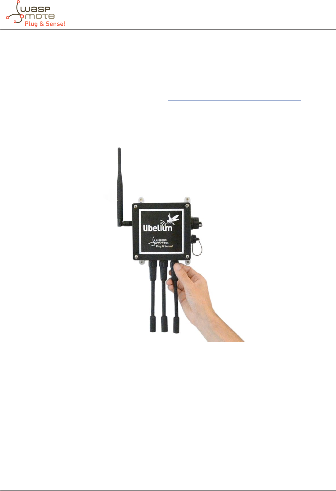
Figure: Waspmote Plug & Sense! Line
-7- v5.4
Waspmote Plug & Sense! - Sensors Guide
3. Sensors
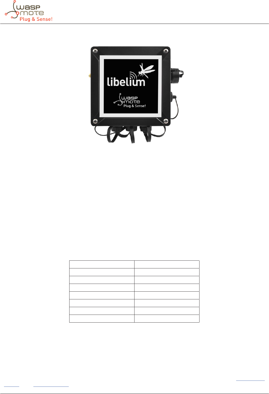
Figure: Image of Waspmote Plug & Sense!
3.1. Internal sensors
3.1.1. Accelerometer
Waspmote has a built in acceleration sensor LIS3331LDH STMicroelectronics which informs the mote of acceleration variations
experienced on each one of the 3 axes (X, Y, Z).
The integration of this sensor allows the measurement of acceleration on the 3 axes (X, Y, Z), establishing 4 kinds of events: Free
Fall, inertial wake up, 6D movement and 6D position, as mentioned in the Waspmote Technical Guide.
The LIS331DLH has dynamically user selectable full scales of ±2g/±4g/±8g and it is capable of measuring accelerations with
output data rates from 0.5 Hz to 1 kHz.
The device features ultra low-power operational modes that allow advanced power saving and smart sleep to wake-up functions.
The accelerometer has 7 power modes, the output data rate (ODR) will depend on the power mode selected. The power modes
and output data rates are shown in this table:
Power Mode Output Data Rate (Hz)
Power Down --
Normal Mode 1000
Low-power 1 0.5
Low-power 2 1
Low-power 3 2
Low-power 4 5
Low-power 5 10
This accelerometer has an auto-test capability that allows the user to check the functioning of the sensor in the nal application.
Its operational temperature range is between -40ºC and +85ºC.
The accelerometer communicates with the microcontroller through the I2C interface. The pins that are used for this task are the
SCL pin and the SDA pin, as well as another INT pin to generate the interruptions.
The accelerometer has 4 types of event which can generate an interrupt: free fall, inertial wake up, 6D movement and 6D
position. These thresholds and times are set in the WaspACC.h le.
Please refer to the Waspmote Technical Guide for more information about how to handle the accelerometer in the Development
section of the Libelium Website.
-8- v5.4
Waspmote Plug & Sense! - Sensors Guide
3.1.2. RTC temperature sensor
The Waspmote RTC (DS3231SN from Maxim) has a built in internal temperature sensor which it uses to recalibrate itself.
Waspmote can access the value of this sensor through the I2C bus.
The sensor is shown in a 10-bit two’s complement format. It has a resolution of 0.25ºC. The measurable temperature range is
between -40ºC and +85ºC.
The sensor is prepared to measure the temperature of the board itself and can thereby compensate for oscillations in the quartz
crystal it uses as a clock. As it is a sensor built in to the RTC, for any application that requires a probe temperature sensor, this
must be integrated from the micro’s analog and digital inputs, as has been done in the case of the sensor boards designed by
Libelium.
Please refer to the Waspmote Technical Guide for more information about how to handle the accelerometer in the Development
section of the Libelium Website.
3.2. Sensor probes
All sensing capabilities of Waspmote Plug & Sense! are provided by sensor probes. Each sensor probe contains one sensor, some
necessary protections against outdoor environmental conditions and a waterproof male connector.
The standard length of a sensor probe is about 150 mm, including waterproof connector, but it could vary due to some sensors
need special dimensions. Weight of a standard probe rounds 20 g (gases probes, temperature and humidity (Sensirion), etc), but
there are some special cases which can rise this weight.
Sensor probes are designed to be used in vertical position (with sensor looking to the ground). In this position, the protection
cap of each sensor probe is eective against rain.
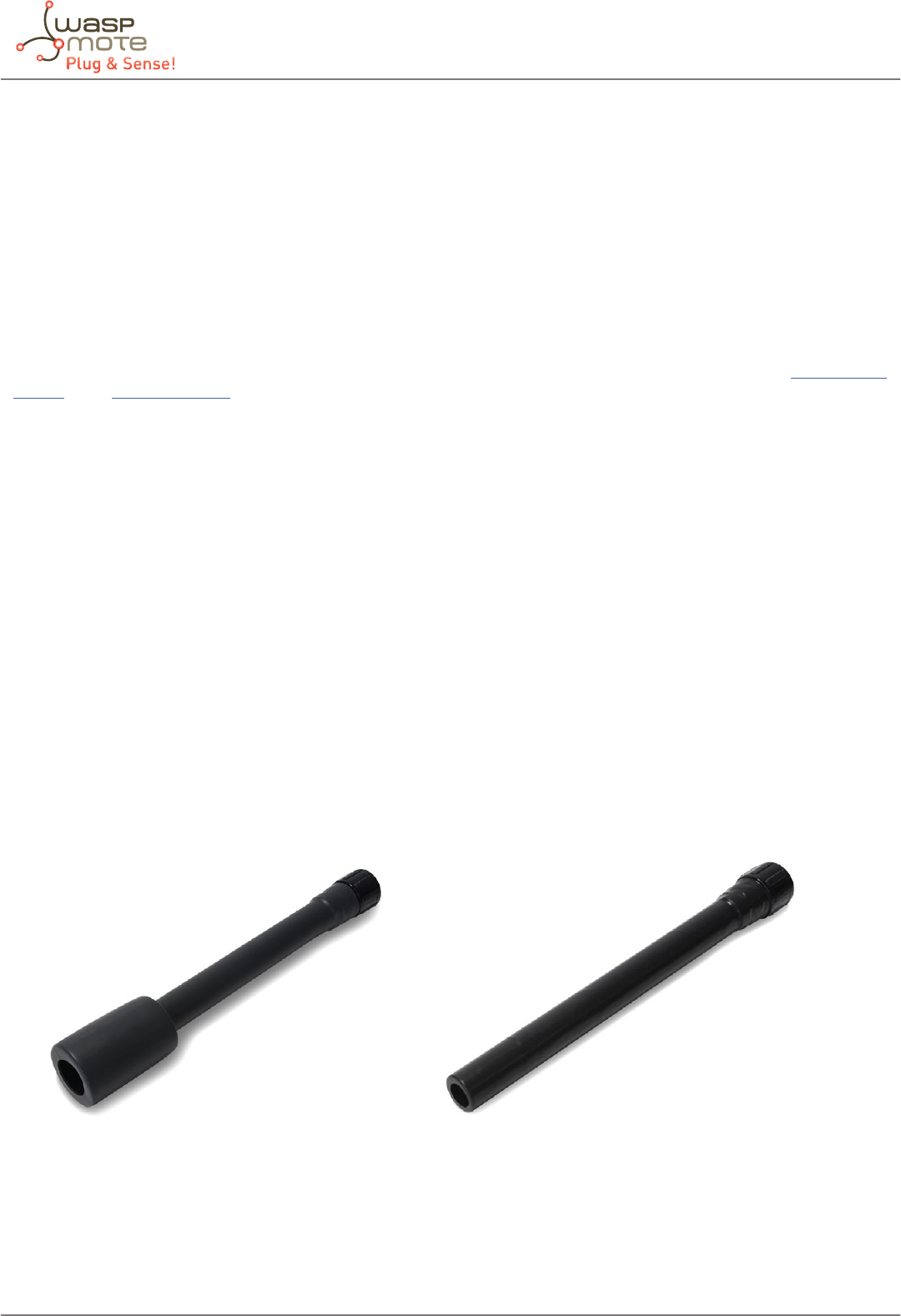
New sensor probes
According to the feedback received from customers and as a part of Libelium Quality Service Policy, Libelium has designed new
rigid sensor probes. They consist of a solid tube protecting the sensor to get them always straight and standardize as maximum
as possible the size and shape of the probes. This avoids bending and deliver a more professional nish to each node. The result
is more esthetic and probes are uniform.
Figure: New sensor probes
-9- v5.4
Waspmote Plug & Sense! - Sensors Guide
4. Smart Environment
4.1. General description
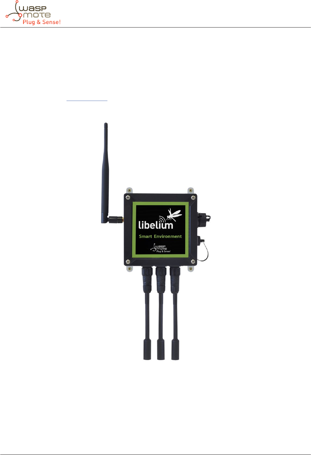
Smart Environment model is designed to monitor environmental parameters such as temperature, humidity, atmospheric
pressure and some types of gases. The main applications for this Waspmote Plug & Sense! conguration are city pollution
measurement, emissions from farms and hatcheries, control of chemical and industrial processes, forest res, etc. Go to the
application section in the Libelium website for a complete list of services.
Figure: Smart Environment Waspmote Plug & Sense! model

-10- v5.4
Waspmote Plug & Sense! - Sensors Guide
Sensor sockets are congured as shown in the gure below.
Sensor
Socket
Sensor probes allowed for each sensor socket
Parameter Reference
A
Temperature 9203
Carbon monoxide - CO 9229
Methane - CH49232
Ammonia – NH39233
Liqueed Petroleum Gases: H2, CH4, ethanol, isobutene 9234
Air pollutants 1: C4H10, CH3CH2OH, H2, CO, CH49235
Air pollutants 2: C6H5CH3, H2S, CH3CH2OH, NH3, H29236
Alcohol derivates: CH3CH2OH, H2, C4H10, CO, CH49237
B
Humidity 9204
Atmospheric pressure 9250
C Carbon dioxide - CO29230
D Nitrogen dioxide - NO29238 , 9238 -B
E
Ozone - O39258 , 9258 -B
Hydrocarbons - VOC 9201 , 9201-B
Oxygen - O29231
F
Carbon monoxide - CO 9229
Methane - CH49232
Ammonia – NH39233
Liqueed Petroleum Gases: H2, CH4, ethanol, isobutene 9234
Air pollutants 1: C4H10, CH3CH2OH, H2, CO, CH49235
Air pollutants 2: C6H5CH3, H2S, CH3CH2OH, NH3, H29236
Alcohol derivates: CH3CH2OH, H2, C4H10, CO, CH49237
Figure: Sensor sockets conguration for Smart Environment model
Note: For more technical information about each sensor probe go to the Development section in Libelium Website.
-11- v5.4
Waspmote Plug & Sense! - Sensors Guide
4.2. Temperature sensor probe
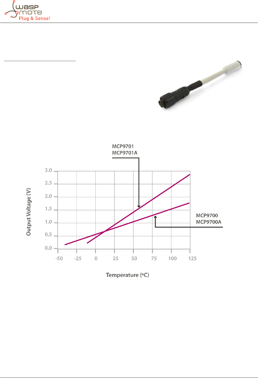
Sensor specications (MCP9700A)
Measurement range: [-40ºC ,+125ºC]
Output voltage (0ºC): 500mV
Sensitivity: 10mV/ºC
Accuracy: ±2ºC (range 0ºC ~ +70ºC), ±4ºC (range -40 ~ +125ºC)
Supply voltage: 2.3 ~ 5.5V
Response time: 1.65 seconds (63% response from +30 to +125°C).
Typical consumption: 6μA
Maximum consumption: 12μA
Figure: Graph of the MCP9700A sensor output voltage with respect to temperature, taken from the Microchip sensor’s data sheet
The MCP9700A is an analog sensor which converts a temperature value into a proportional analog voltage. The range of output
voltages is between 100mV (-40°) and 1.75V (125°C), resulting in a variation of 10mV/°C, with 500mV of output for 0°C.
Figure: Image of the Temperature sensor probe (MCP9700A)
-12- v5.4
Waspmote Plug & Sense! - Sensors Guide
4.3. Humidity sensor probe
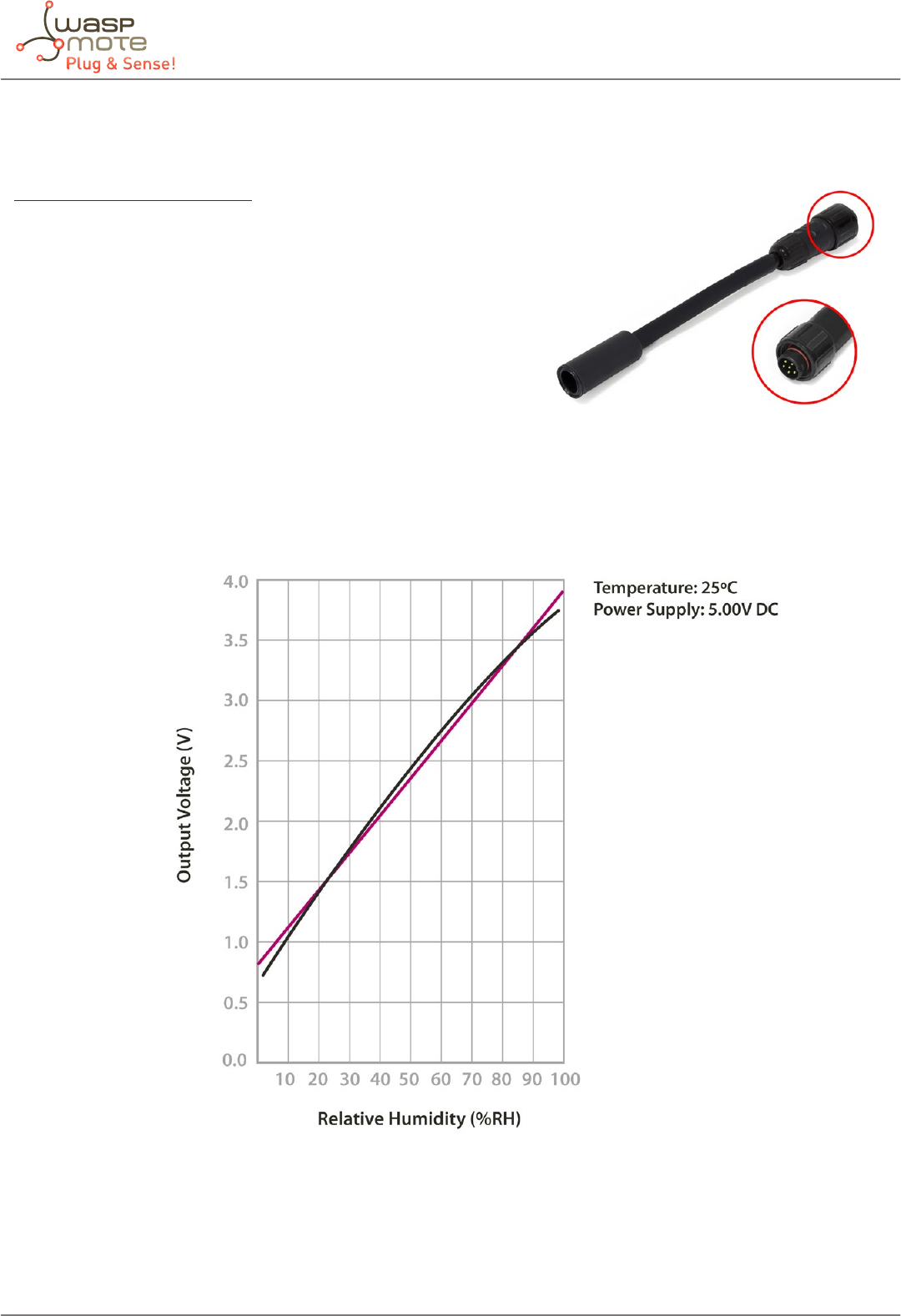
Sensor specications (808H5V5)
Measurement range: 0 ~ 100%RH
Output signal: 0.8 ~ 3.9V (25ºC)
Accuracy: <±4%RH (at 25ºC, range 30 ~ 80%), <±6%RH (range 0 ~ 100)
Supply voltage: 5VDC ±5%
Operating temperature: -40 ~ +85ºC
Response time: <15 seconds
Typical consumption: 0.38mA
Maximum consumption: 0.5mA
Figure: 808H5V5 humidity sensor output taken from the Sencera Co. Ltd sensor data sheet
This is an analog sensor which provides a voltage output proportional to the relative humidity in the atmosphere. As the
sensor’s signal range is outside of that permitted to the Waspmote’s input, a voltage divider has been installed which converts
the output voltage to values between 0.48 ~ 2.34V.
Figure: Image of the Humidity sensor probe (808H5V5)
-13- v5.4
Waspmote Plug & Sense! - Sensors Guide
4.4. Atmospheric Pressure sensor probe
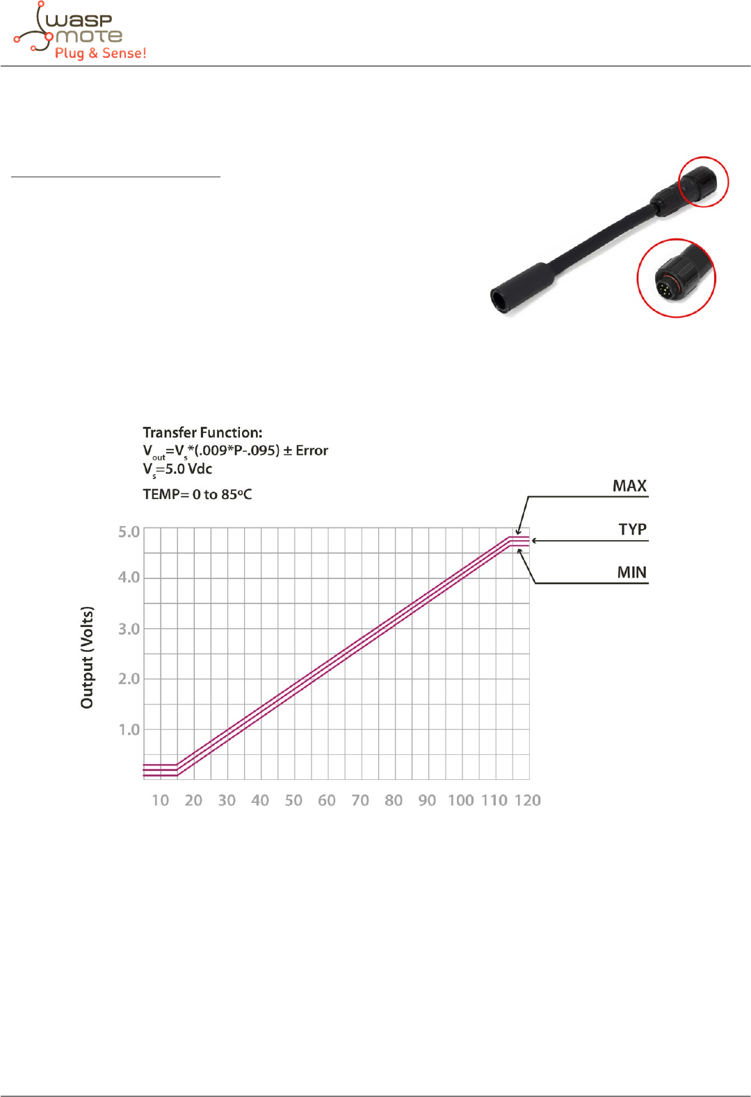
Sensor specications (MPX4115A)
Measurement range: 15 ~ 115kPa
Output signal: 0,2 ~ 4,8V (0 ~ 85ºC)
Sensitivity: 46mV/kPa
Accuracy: <±1,5%V (0 ~ 85ºC)
Typical consumption: 7mA
Maximum consumption: 10mA
Supply voltage: 4.85 ~ 5.35V
Operation temperature: -40 ~ +125ºC
Storage temperature: -40 ~ +125ºC
Response time: 20ms
Figure: Graph of the MPX4115A sensor’s output voltage with regard to pressure taken from the Freescale sensor’s data sheet
The MPX4115A sensor converts atmospheric pressure to an analog voltage value in a range covering between 0.2V and 4.8V. As
this is a range which exceeds the maximum value admitted by Waspmote, its output has been adapted to t in a range between
0.12V and 2.88V.
Figure: Image of the Atmospheric Pressure sensor probe (MPX4115A)
-14- v5.4
Waspmote Plug & Sense! - Sensors Guide
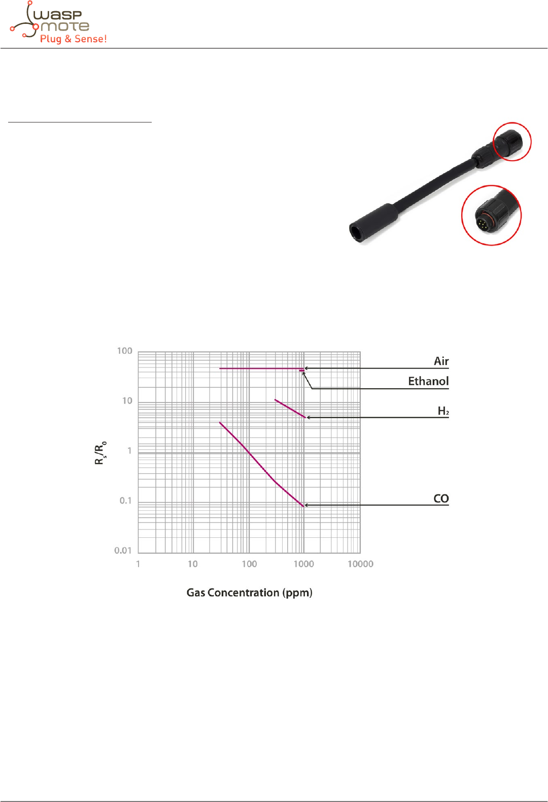
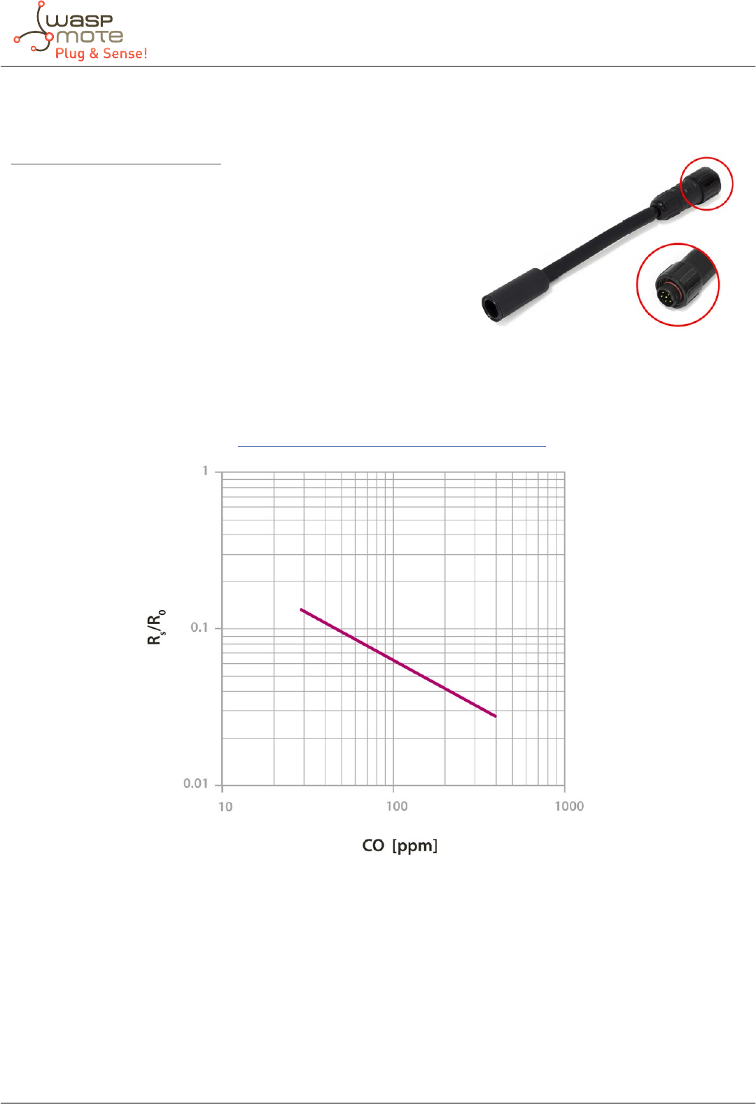
4.5. Carbon Monoxide (CO) sensor probe
Sensor specications (TGS2442)
Gases: CO
Measurement range: 30 ~ 1000ppm
Resistance at 100ppm: 13.3 ~ 133kΩ
Sensibility: 0.13 ~ 0.31 (ratio between the resistance at
300ppm and at 100ppm)
Supply voltage: 5V ±0.2V DC
Operating temperature: -10 ~ +50ºC
Response time: 1second
Minimum load resistance: 10kΩ
Average consumption: 3mA (throughout the complete
power supply cycle in one second)
Figure: Graph of the sensitivity of the TGS2442 taken from the Figaro sensor’s data sheet
The TGS2442 is a resistive sensor sensitive to the changes in concentration of Carbon Monoxide (CO) and, very slightly,
Hydrogen (H2). The sensor’s resistance varies according to the graph in the gure above, which may present signicant variations
between two dierent sensors, so it is recommended to consult the sensor’s documentation to choose the load resistance and
amplication gain and calibrate it before nally inserting it into the application.
Figure: Image of the CO sensor probe (TGS2442)
-15- v5.4
Waspmote Plug & Sense! - Sensors Guide
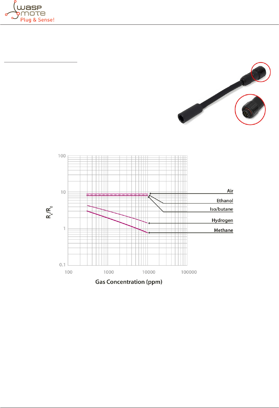
4.6. Methane (CH4) sensor probe
Sensor specications (TGS2611)
Gases: CH4, H2
Measurement range: 500 ~ 10000ppm
Resistance at 5000ppm: 0.68 ~ 6.8kΩ
Sensitivity: 0.6 ± 0.06 (ratio between the resistance at 9000 and at 3000ppm)
Supply voltage: 5V ±0.2V DC
Operating temperature: -10 ~ +40ºC
Response time: 30 seconds
Minimum load resistance: 0.45kΩ
Average consumption: 61mA
Figure: Graph of sensitivity of the TGS2611 taken from the Figaro sensor’s data sheet
The TGS2611 sensor shows a variable resistance with the concentration of CH4 and to a lesser extent with the concentration of
H2. The sensor’s initial resistance (for 5000ppm) and its sensitivity may show large variations between dierent sensors of the
same model, so it is recommended to consult the manufacturer’s documentation and calibrate it before nally inserting it in
the application.
Figure: Image of the CH4 sensor probe (TGS2611)
-16- v5.4
Waspmote Plug & Sense! - Sensors Guide
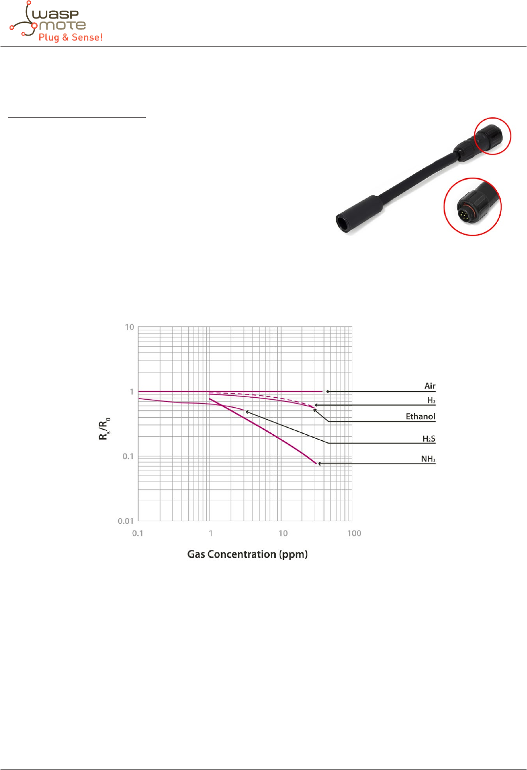
4.7. Ammonia (NH3) sensor probe
Sensor specications (TGS2444)
Gases: NH3, H2S
Measurement range: 10 ~ 100ppm
Resistance at 10ppm: 3.63 ~ 36.3kΩ
Sensitivity: 0,063 ~ 0.63 (ratio between the resistance at 3000 and
at 1000ppm)
Supply voltage: 5V ±0.2V DC
Operating temperature: -10 ~ +50ºC
Response time: 250ms
Minimum load resistance: 8kΩ
Average consumption: 12mA (throughout the complete power
supply cycle in 250ms)
Figure: Graph of the sensitivity of the TGS2444 taken from the Figaro sensor data sheet
The TGS2444 sensor is a resistive sensor which is highly sensitive to variations in the concentration of Ammonia (NH3) and
which shows slight sensitivity to hydrogen sulphide (H2S) and to a lesser extent, to Hydrogen (H2) and Ethanol (CH3CH2OH). Both
the sensor’s initial resistance (at 10ppm) and its sensitivity vary widely between dierent sensors of the same model, so it is
recommended to calibrate each one of them independently before nally including them in the application.
Figure: Image of the NH3 sensor probe (TGS2444)
-17- v5.4
Waspmote Plug & Sense! - Sensors Guide
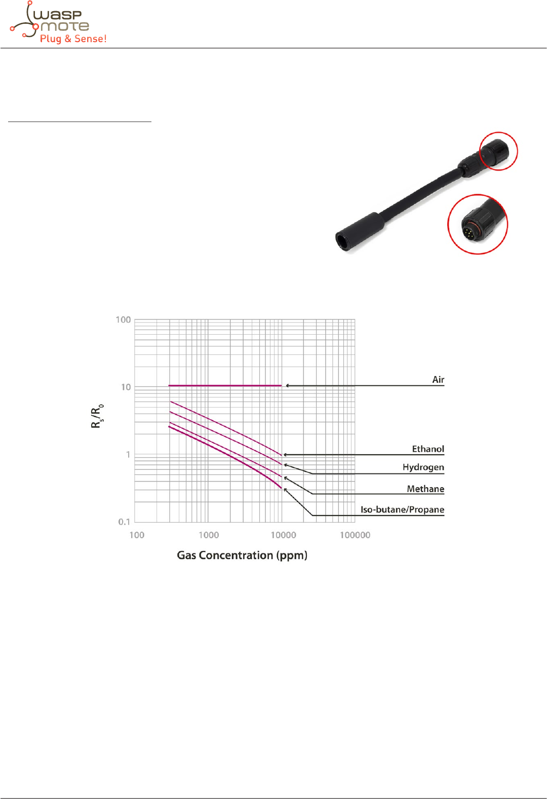
4.8. LPG sensor probe
Sensor specications (TGS2610)
Gases: CH3CH2OH, CH4, C4H10, H2
Measurement range: 500 ~ 10000ppm
Resistance at 1800ppm (isobutane): 0.68 ~ 6.8kΩ
Sensitivity: 0.56 ± 0.06 (ratio between the resistance at 3000 and at
1000ppm)
Supply voltage: 5V ±0.2V DC
Operating temperature: -10 ~ +40ºC
Response time: 30 seconds
Minimum load resistance: 0.45kΩ
Average consumption: 61mA
Figure: Graph of the sensitivity of the TGS2610 taken from the Figaro sensor’s data sheet
The TGS2610 is a resistive sensor which shows sensitivity to combustible gases and derivatives. Especially reactive to Isobutane
(C4H10), it is also sensitive to Methane (CH4), Ethanol (CH3CH2OH) and Hydrogen (H2). Because both its resistance and sensitivity
show signicant variations between dierent sensors of the same model, it is recommended to consult the manufacturer’s
documentation and carry out a process of calibration prior to its nal inclusion in an application.
Figure: Image of the LPG sensor probe (TGS2610)
-18- v5.4
Waspmote Plug & Sense! - Sensors Guide
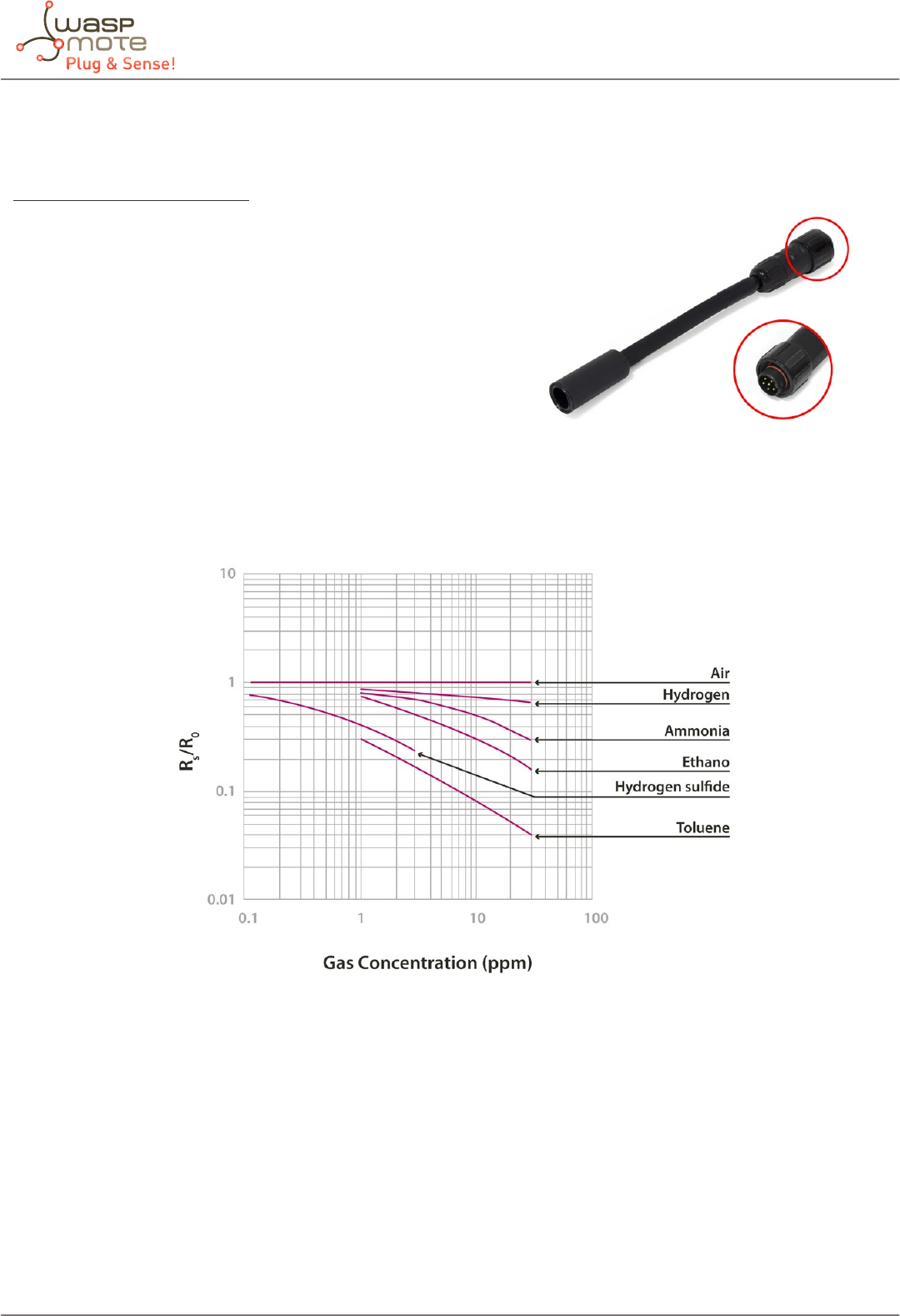
4.9. Air Pollutants 1 sensor probe
Sensor specications (TGS2602)
Gases: C6H5CH3, H2S, CH3CH2OH, NH3, H2
Measurement range: 1 ~ 30ppm
Air resistance: 10 ~ 100kΩ
Sensitivity: 0.15 ~ 0.5 (ratio between the resistance in 10ppm of
Ethanol and in air)
Supply voltage: 5V ±0.2V DC
Operating temperature: +10 ~ +50ºC
Storage temperature: -20 ~ +60ºC
Response time: 30 seconds
Minimum load resistance: 0.45kΩ
Average consumption: 61mA
Figure: Graph of the sensitivity of the TGS2602 taken from the Figaro sensor’s data sheet
The TGS2602 is a sensor similar to the TGS2600 which reacts varying its resistance in the presence of contaminant gases, mainly
Toluene (C6H5CH3), Hydrogen Sulphide (H2S), Ethanol (CH3CH2OH), Ammonia (NH3) and to a lesser extent, Hydrogen (H2). In
air without contaminants the sensor shows a resistance between 10 and 100kΩ with a variation ratio between 0.15 and 0.5
between the resistance in 10ppm of CH3CH2OH and this one. This variability makes a calibration of the sensor necessary before
using it in a nal application.
Figure: Image of the Air Pollutants 1 sensor probe (TGS2602)
-19- v5.4
Waspmote Plug & Sense! - Sensors Guide
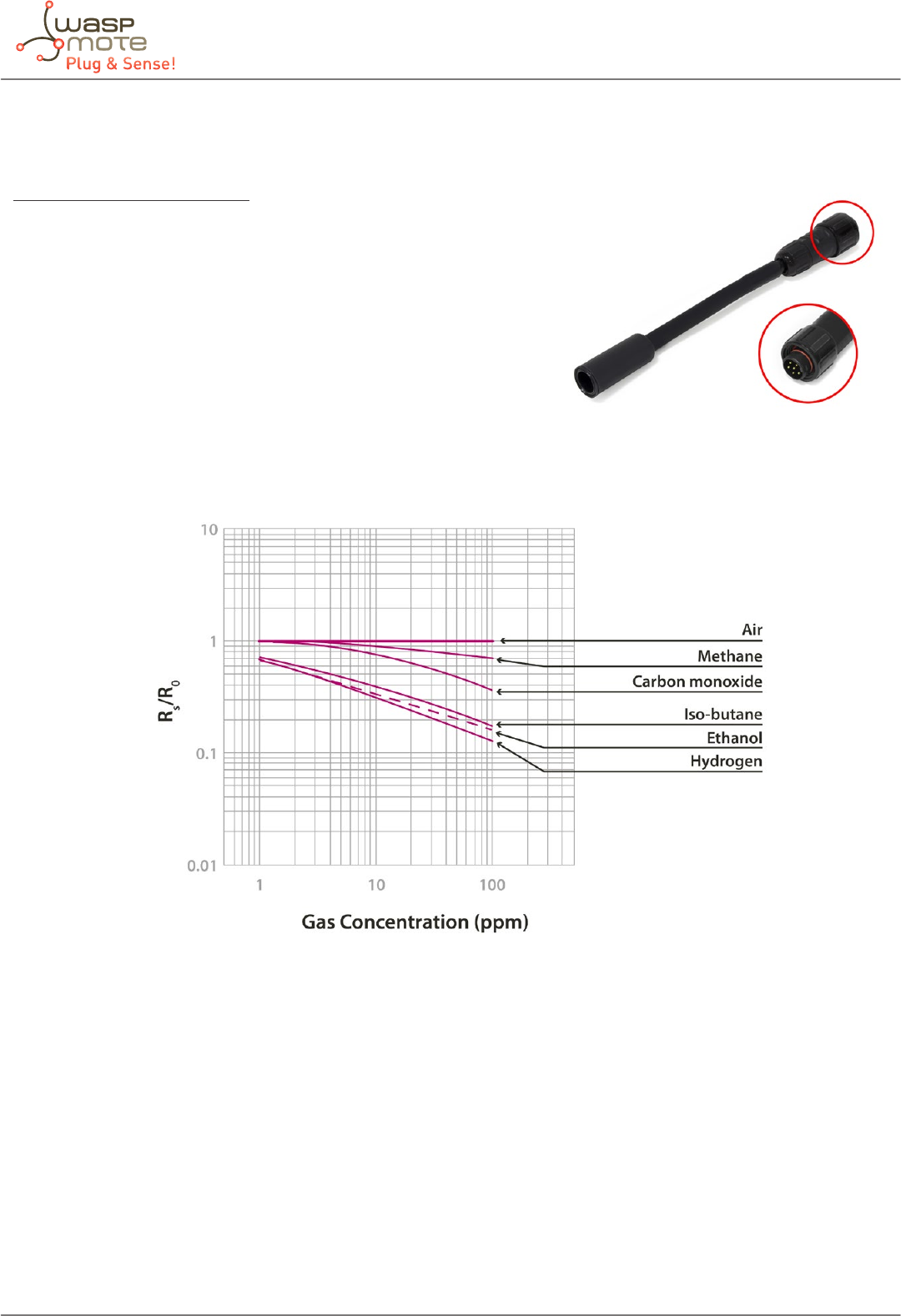
4.10. Air pollutants 2 sensor probe
Sensor specications (TGS2600)
Gases: C4H10, CH3CH2OH, H2, CO, CH4
Measurement range: 1 ~ 100ppm
Air resistance: 10 ~ 90kΩ
Sensitivity: 0.3 ~ 0.6 (ratio between the resistance in 10ppm of H2 and
in air)
Supply voltage: 5V ±0.2V DC
Operating temperature: -10 ~ +40ºC
Response time: 30 seconds
Minimum load resistance: 0.45kΩ
Average consumption: 46mA
Figure: Graph of the sensitivity of the TGS2600 taken from the Figaro sensor’s data sheet
The TGS2600 sensor shows sensitivity to the variation of the concentration of numerous gases that are not usually found in the
composition of the atmosphere and which are considered contaminants. Amongst these would be mainly, Ethanol (CH3CH2OH)
and Isobutane (C4H10) and, with less response, Carbon Monoxide (CO) and Methane (CH4). This sensor is also sensitive to variations
in the concentration of Hydrogen (H2). The sensor’s resistance in air would vary between 10 and 90kΩ, with a ratio of sensitivity
between 0.3 and 0.6 for an H2 concentration of 10ppm. Because of this variability it is recommended to calibrate each one of the
sensors prior to their use in a nal application.
Figure: Image of the Air Pollutants 2 sensor probe (TGS2600)
-20- v5.4
Waspmote Plug & Sense! - Sensors Guide
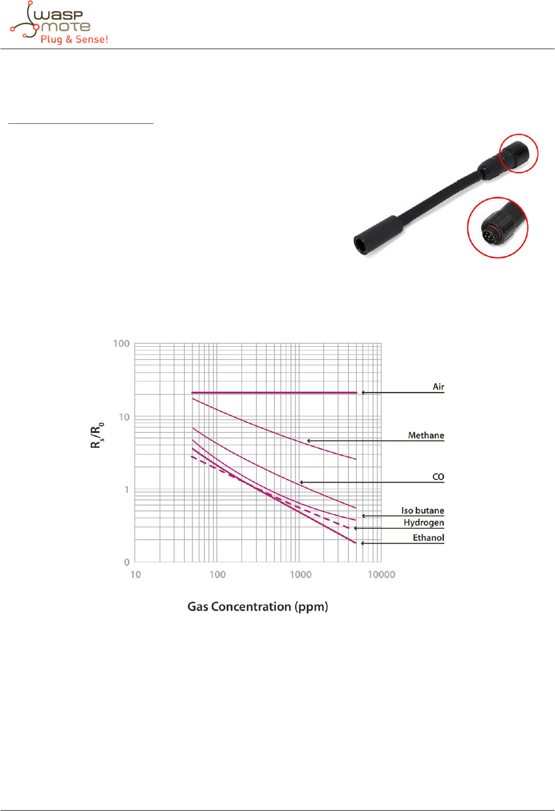
4.11. Solvent Vapors sensor probe
Sensor specications (TGS2620)
Gases: CH3CH2OH, H2, C4H10, CO, CH4
Measurement range: 50 ~ 5000ppm
Resistance to 300ppm of Ethanol: 1 ~ 5kΩ
Sensitivity: 0.3 ~ 0.5 (ratio between the resistance at 300ppm and at
50ppm)
Supply voltage: 5V ±0.2V DC
Operating temperature: -10 ~ +40ºC
Response time: 30 seconds
Load minimum resistance: 0.45kΩ
Average consumption: 46mA (throughout the complete power supply
cycle in 250ms)
Figure: Graph of the sensitivity of the TGS2620 taken from the Figaro sensor’s data sheet
The TGS2620 sensor allows detection of alcohol and organic gases, mainly Ethanol (CH3CH2OH), Hydrogen (H2), Isobutane
(C4H10), Carbon Monoxide (CO) and Methane (CH4). The resistance the sensor shows in a 300ppm concentration of Ethanol can
vary between 1 and 5kΩ, while the sensitivity ratio between this and the resistance in 50ppm varies between 0.3 and 0.5. As a
consequence of these variations it is necessary to calibrate each sensor before their insertion into a nal application.
Figure: Image of the Solvent Vapors sensor probe (TGS2620)
-21- v5.4
Waspmote Plug & Sense! - Sensors Guide
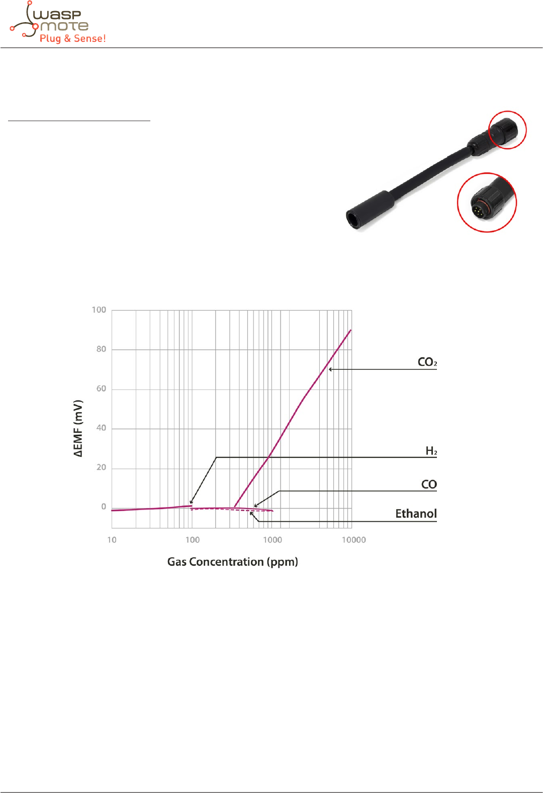
4.12. Carbon Dioxide (CO2) sensor probe
Sensor specications (TGS4161)
Gases: CO2
Measurement range: 350 ~ 10000ppm
Voltage at 350ppm: 220 ~ 490mV
Sensitivity: 44 ~ 72mV (variation between the voltage at 350ppm and
at 3500ppm)
Supply voltage: 5V ±0.2V DC
Operating temperature: -10 ~ +50ºC
Response time: 1.5 minutes
Average consumption: 50mA
Figure: Graph of the sensitivity of the TGS4161 sensor taken from the Figaro sensor’s data sheet
The TGS4161 sensor provides a voltage output proportional to the CO2 concentration in the atmosphere. It shows a value
between 220 and 490mV for a concentration of 350ppm (approximately the normal CO2 concentration in the air) decreasing as
the amount of gas increases. Dierent sensors may show a large variability in the initial voltage values at 350ppm and sensitivity,
so it is recommended to calibrate each sensor before including it in the application.
Figure: Image of the CO2 sensor probe (TGS4161)
-22- v5.4
Waspmote Plug & Sense! - Sensors Guide
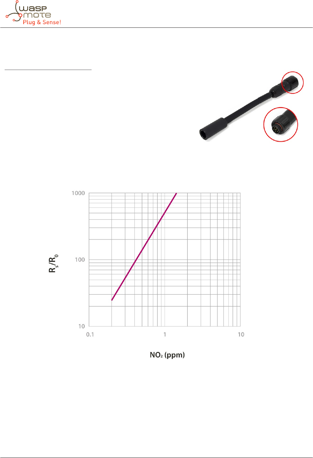
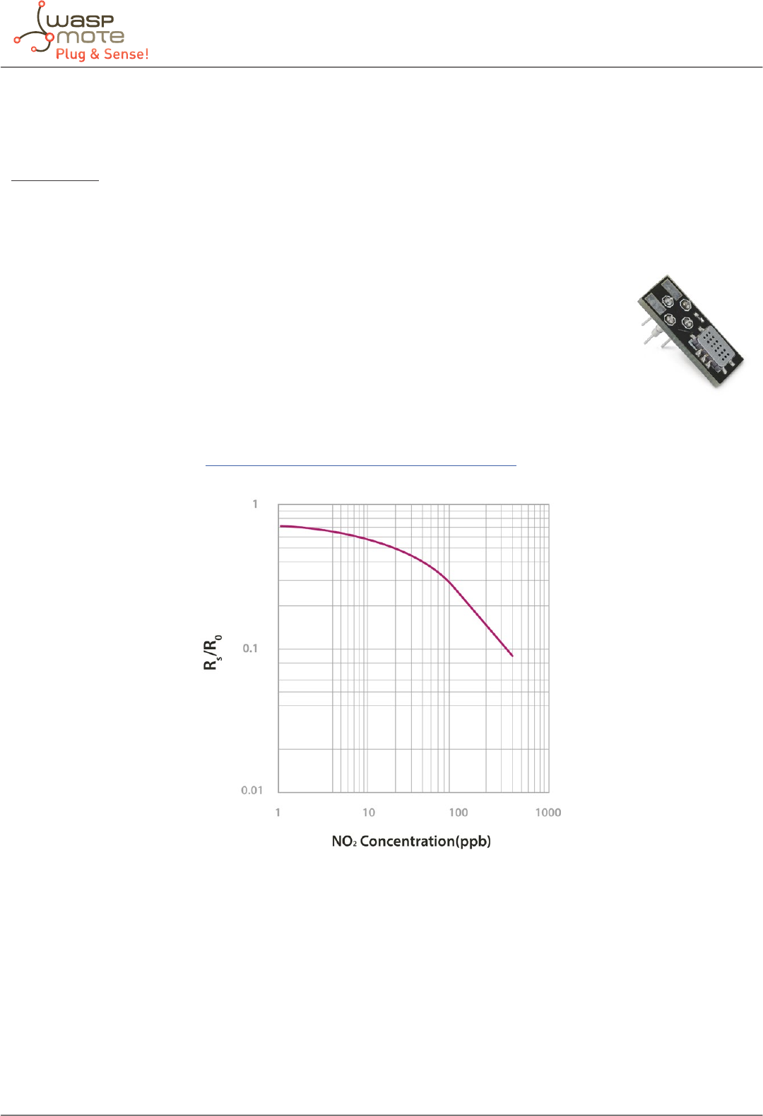
4.13. Nitrogen Dioxide (NO2) sensor probe (MiCS-2710)
Sensor specications (MiCS-2710)
Gases: NO2
Measurement range: 0.05 ~ 5ppm
Air resistance: 0.8 ~ 8kΩ (typically 2.2kΩ)
Sensitivity: 6 ~ 100 (typically 55, ratio between the resistance
at 0.25ppm and in air)
Supply voltage: 1.7 ~ 2.5V DC
Operating temperature: -30 ~ +85ºC
Response time: 30 seconds
Average consumption: 26mA (throughout the complete
power supply cycle in one second)
Figure: Graph of the sensitivity of the MiCS-2710 taken from the e2v’s sensor data
The MiCS-2710 is a sensor whose resistance varies in the presence of small concentrations of NO2. This value varies between 2kΩ
and 2MΩ approximately, providing high accuracy throughout the output range. Unlike the rest of the board’s gas sensors, which
operate at a voltage of 5V, this sensor is powered through a 1.8V voltage regulator, with consumption of approximately 26mA.
The sensor’s resistance in air, as well as its sensitivity, can vary between dierent units, so it is recommended to calibrate each
one of them before nally inserting them in the application.
Figure: Image of the NO2 sensor probe (MiCS-2710)
-23- v5.4
Waspmote Plug & Sense! - Sensors Guide
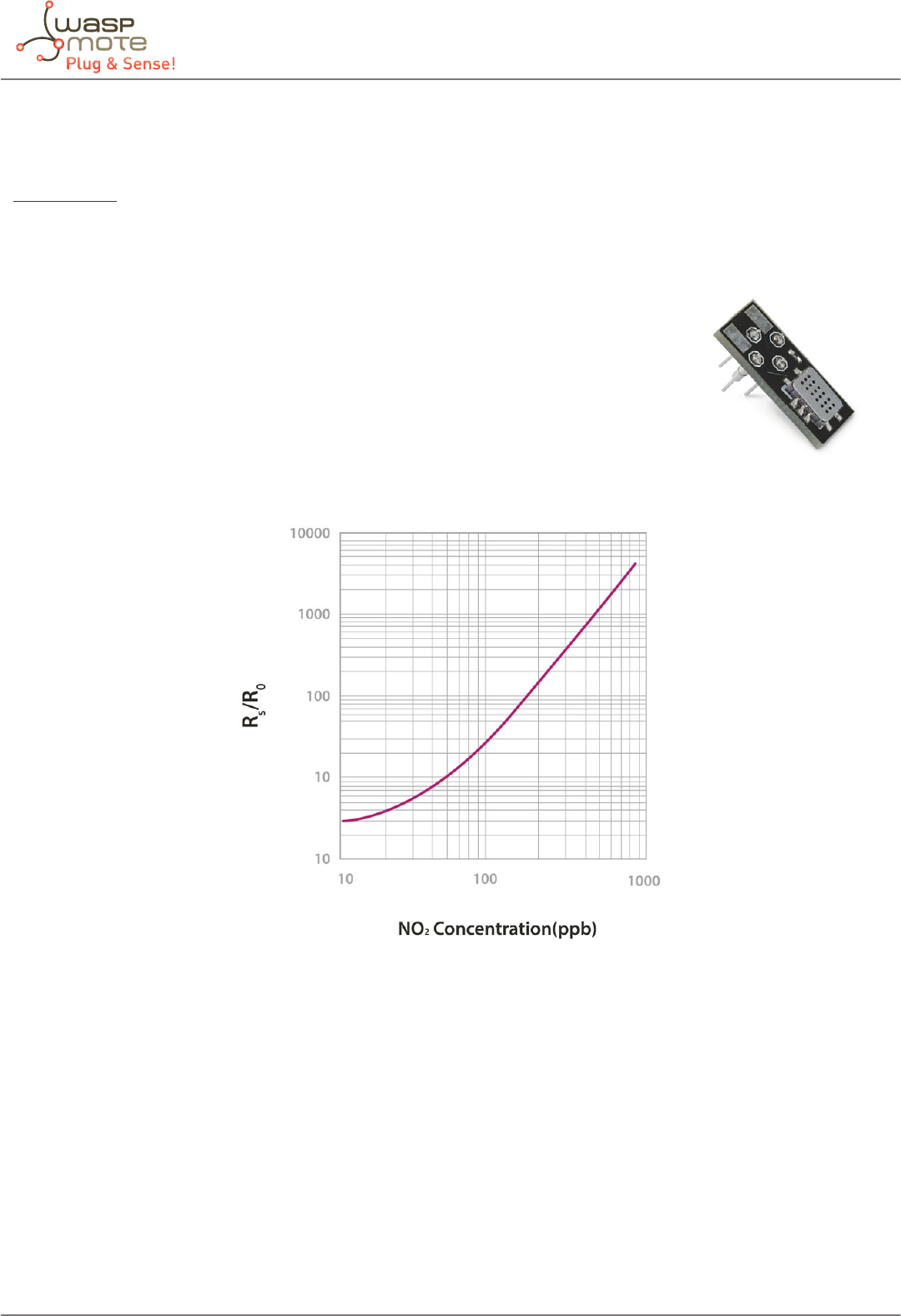
4.14. Nitrogen Dioxide (NO2) Sensor - MiCS-2714
Specications
This sensor is the new version for the MiCS-2710 sensor. The new version is provided since June 2014 and has similar specications:
Gases: NO2
Measurement range: 0.05 ~ 5ppm
Air resistance: 0.8 ~ 8kΩ (typically 2.2kΩ)
Sensitivity: 6 ~ 100 (typically 55, ratio between the resistance at 0.25ppm and in air)
Supply voltage: 1.7 ~ 2.5V DC
Operating temperature: -30 ~ +85ºC
Response time: 30 seconds
Average consumption: 26mA (throughout the complete power supply cycle in one second)
Figure: Graph of the sensitivity of the MiCS-2714 taken from the e2v’s sensor data.
The MiCS-2714 is a sensor whose resistance varies in the presence of small concentrations of NO2. This value varies between 2kΩ
and 2MΩ approximately, providing high accuracy throughout the output range. Unlike the rest of the board’s gas sensors, which
operate at a voltage of 5V, this sensor is powered through a 1.8V voltage regulator, with consumption of approximately 26mA.
The sensor’s resistance in air, as well as its sensitivity, can vary between dierent units, so it is recommended to calibrate each
one of them before nally inserting them in the application.
Figure: Image of the MiCS-2714 sensor
-24- v5.4
Waspmote Plug & Sense! - Sensors Guide
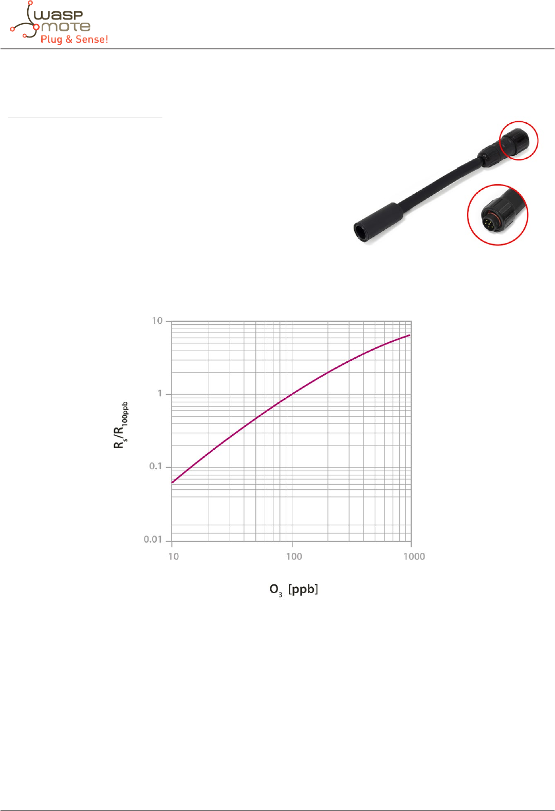
4.15. Ozone (O3) sensor probe (MiCS-2610)
Sensor specications (MiCS-2610)
Gases: O3
Measurement range: 10 ~ 1000ppb
Air resistance: 3 ~ 60kΩ (typically 11kΩ)
Sensitivity: 2 ~ 4 (typically 1.5, ratio between the resistance at
100ppm and at 50ppm)
Supply voltage: 1.95 ~ 5V DC
Operating temperature: -30 ~ +85ºC
Response time: 30 seconds
Average consumption: 34mA
Figure: Graph of the sensitivity of the MiCS-2610 taken from the e2v’s sensor data
The MiCS-2610 is a resistive sensor that allows to measure the variation of the O3 concentration between 10ppb and 1000ppb.
It’s resistance varies between 11kΩ and 2MΩ approximately. Unlike the MiCS-2710, this sensor is powered through a 2.5V
voltage regulator, with consumption of approximately 34mA. The sensor’s resistance in air, as well as its sensitivity, can vary
between dierent units, so it is recommended to calibrate each one of them before nally inserting them in the application.
Figure: Image of the O3 sensor probe (MiCS-2610)
-25- v5.4
Waspmote Plug & Sense! - Sensors Guide
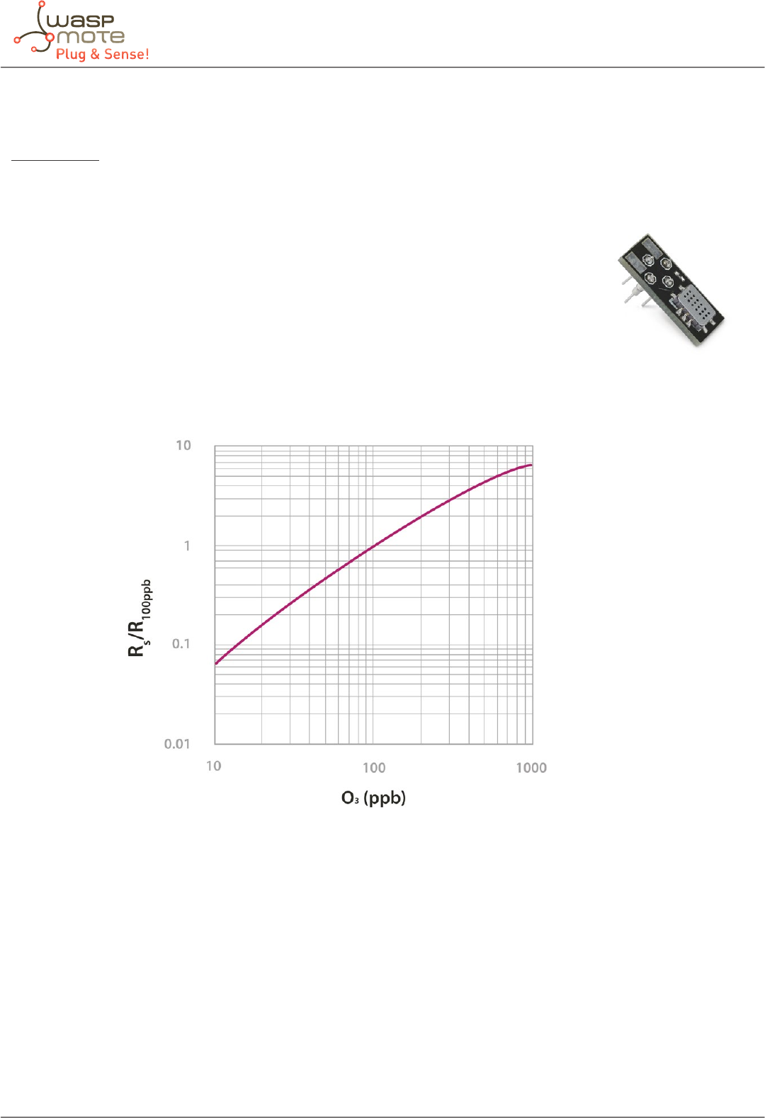
4.16. Ozone (O3) Sensor - MiCS-2614
Specications
This sensor is the new version for the MiCS-2610 sensor. The new version is provided since June 2014 and has similar specications:
Gases: O3
Measurement range: 10 ~ 1000ppb
Air resistance: 3 ~ 60kΩ (typically 11kΩ)
Sensitivity: 2 ~ 4 (typically 1.5, ratio between the resistance at 100ppb and at 50ppb)
Supply voltage: 1.95 ~ 5V DC
Operating temperature: -30 ~ +85ºC
Response time: 30 seconds
Average consumption: 34mA
Figure: Graph of the sensitivity of the MiCS-2614 taken from the e2v’s sensor data
The MiCS-2614 is a resistive sensor that allows to measure the variation of the O3 concentration between 10ppb and 1000ppb.
It’s resistance varies between 11kΩ and 2MΩ approximately. Unlike the MiCS-2710, this sensor is powered through a 2.5V
voltage regulator, with consumption of approximately 34mA. The sensor’s resistance in air, as well as its sensitivity, can vary
between dierent units, so it is recommended to calibrate each one of them before nally inserting them in the application.
Figure: Image of the MiCS-2614 sensor
-26- v5.4
Waspmote Plug & Sense! - Sensors Guide
4.17. VOC sensor probe (MiCS-5521)
Sensor specications (MiCS-5521)
Gases: CO, Hydrocarbons, Volatile Organic Compounds *
Measurement range: 30 ~ 400ppm
Air resistance: 100 ~ 1000kΩ
Sensitivity: 1.8 ~ 6 (typically 3, ratio between the resistance at
60ppm and at 200ppm of CO)
Supply voltage: 2.1 ~ 5V DC
Operating temperature: -30 ~ +85ºC
Response time: 30 seconds
Average consumption: 32mA
(*) Chlorinated hydrocarbons, aromatic hydrocarbons, aromatic alcohols, aliphatic alcohols, terpenes, glycols, aldehydes, esters
and acids. Detailed list can be found at http://www.libelium.com/downloads/voc-sensors.xls
Figure: Graph of the sensitivity of the MiCS-5521 taken from the e2v’s sensor data
The MiCS-5521 is a resistive sensor that responds to a great variety of gases, such as Carbon Monoxide (CO), Hydrocarbons and
Volatile Organic Compounds. It’s resistance varies between 1000kΩ and 2kΩ approximately. Like the MiCS-2610, the MiCS-5521
is powered through a 2.5V voltage regulator, with consumption of approximately 32mA. The sensor’s resistance in air, as well
as its sensitivity, can vary between dierent units, so it is recommended to calibrate each one of them before nally inserting
them in the application.
Figure: Image of the VOC sensor probe (MiCS-5521)
-27- v5.4
Waspmote Plug & Sense! - Sensors Guide
4.18. VOC sensor (MiCS-5524)
Specications
This sensor is the new version for the MiCS-5521 sensor. The new version is provided since June 2014 and has similar specications:
Gases: CO, Hydrocarbons, Volatile Organic Compounds *
Measurement range: 30 ~ 400ppm
Air resistance: 100 ~ 1500kΩ
Sensitivity: 1.8 ~ 6 (typically 3, ratio between the resistance at 60ppm and at 200ppm of CO)
Supply voltage: 2.1 ~ 5V DC
Operating temperature: -30 ~ +85ºC
Response time: 30 seconds
Average consumption: 32mA
(*) Chlorinated hydrocarbons, aromatic hydrocarbons, aromatic alcohols, aliphatic alcohols, terpenes, glycols, aldehydes, esters and
acids. Detailed list can be found at http://www.libelium.com/downloads/voc-sensors.xls
Figure: Graph of the sensitivity of the MiCS-5524 taken from the e2v’s sensor data
The MiCS-5524 is a resistive sensor that responds to a great variety of gases, such as Carbon Monoxide (CO), Hydrocarbons and
Volatile Organic Compounds. It’s resistance varies between 1000kΩ and 2kΩ approximately. Like the MiCS-2614, the MiCS-5524
is powered through a 2.5V voltage regulator, with consumption of approximately 32mA. The sensor’s resistance in air, as well
as its sensitivity, can vary between dierent units, so it is recommended to calibrate each one of them before nally inserting
them in the application.
Figure: Image of the MiCS-5524 sensor
-28- v5.4
Waspmote Plug & Sense! - Sensors Guide
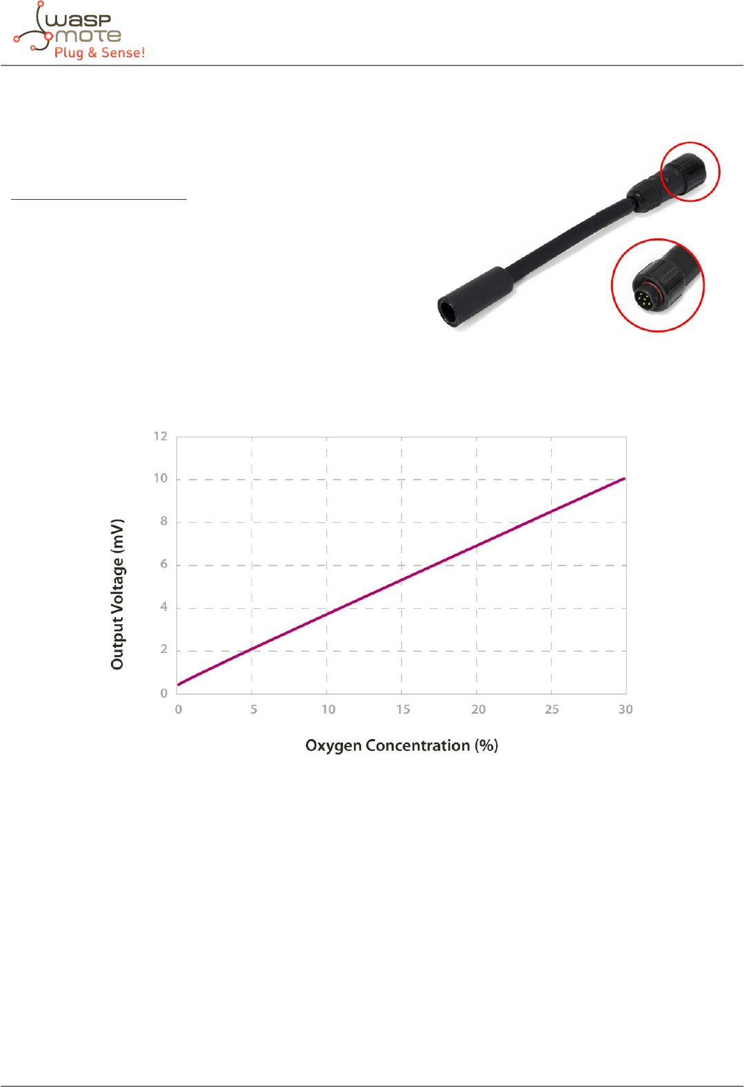
4.19. Oxygen (O2) sensor probe
Sensor specications (SK-25)
Gases: O2
Measurement range: 0 ~ 30%
Output range: Approximately 0 ~ 10mV
Initial Voltage: 5.5 ~ 8.8mV
Operating temperature: 5 ~ +40ºC
Response time: 15 seconds
Consumption: 0μA
Figure: Graph of the sensitivity of the SK-25 extracted from the Figaro sensor’s data sheet
The SK-25 is an analog sensor which provides a voltage output proportional to the O2 concentration in the atmosphere, without
needing power and therefore with zero consumption. It shows an output range between 0 and 10mV, with voltage in standard
conditions (approximately 21% O2 concentration) of between 5.5 and 8.8mV. The output response can vary from one sensor to
another, so it is recommended to calibrate the sensor before nally inserting it into the application.
Figure: Image of the O2 sensor probe (SK-25)
-29- v5.4
Waspmote Plug & Sense! - Sensors Guide
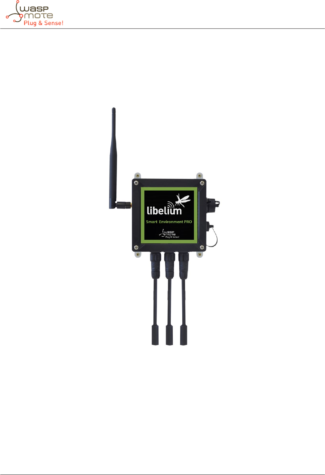
5. Smart Enviroment PRO
5.1. General description
The Smart Environment PRO model has been created as an evolution of Smart Enviroment. It enables the user to implement
pollution, air quality, industrial, environmental or farming projects with high requirements in terms of high accuracy, reliability
and measurement range as the sensors come calibrated from factory.
Figure: Smart Environment PRO Waspmote Plug & Sense! model

-30- v5.4
Waspmote Plug & Sense! - Sensors Guide
Sensor sockets are congured as shown in the gure below.
Sensor
Socket
Sensor probes allowed for each sensor socket
Parameter Reference
A, B, C and F
Carbon Monoxide (CO) [Calibrated] 9371-P
Carbon Dioxide (CO2) [Calibrated] 9372-P
Oxygen (O2) [Calibrated] 9373-P
Ozone (O3) [Calibrated] 9374-P
Nitric Oxide (NO) [Calibrated] 9375-P
Nitric Dioxide (NO2) [Calibrated] 9376-P
Sulfur Dioxide (SO2) [Calibrated] 9377-P
Ammonia (NH3) [Calibrated] 9378-P
Methane (CH4) and Combustible Gas [Calibrated] 9379-P
Hydrogen (H2) [Calibrated] 9380-P
Hydrogen Sulde (H2S) [Calibrated] 9381-P
Hydrogen Chloride (HCl) [Calibrated] 9382-P
Hydrogen Cyanide (HCN) [Calibrated] 9383-P
Phosphine (PH3) [Calibrated] 9384-P
Ethylene (ETO) [Calibrated] 9385-P
Chlorine (Cl2) [Calibrated] 9386-P
D Particle Matter (PM1 / PM2.5 / PM10) - Dust 9387-P
E Temperature, Humidity and Pressure 9370-P
Figure: Sensor sockets conguration for Smart Environment PRO model
Note: For more technical information about each sensor probe go to the Development section in Libelium website.
-31- v5.4
Waspmote Plug & Sense! - Sensors Guide
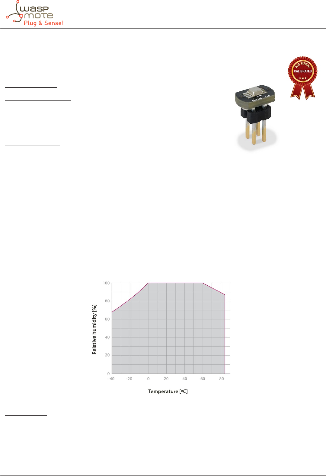
5.2. Temperature, Humidity and Pressure sensor
The BME280 is a digital temperature, humidity and pressure sensor developed by Bosch
Sensortec.
Specications
Electrical characteristics:
Supply voltage: 3.3 V
Sleep current typical: 0.1 μA
Sleep current maximum: 0.3 μA
Temperature sensor:
Operational range: -40 ~ +85 ºC
Full accuracy range: 0 ~ +65 ºC
Accuracy: ±1 ºC (range 0 ºC ~ +65 ºC)
Response time: 1.65 seconds (63% response from +30 to +125 °C).
Typical consumption: 1 μA measuring
Humidity sensor:
Measurement range: 0 ~ 100% of Relative Humidity (for temperatures < 0 °C and > 60 °C see gure below)
Accuracy: < ±3% RH (at 25 ºC, range 20 ~ 80%)
Hysteresis: ±1% RH
Operating temperature: -40 ~ +85 ºC
Response time (63% of step 90% to 0% or 0% to 90%): 1 second
Typical consumption: 1.8 μA measuring
Maximum consumption: 2.8 μA measuring
Figure: Humidity sensor operating range
Pressure sensor
Measurement range: 30 ~ 110 kPa
Operational temperature range: -40 ~ +85 ºC
Full accuracy temperature range: 0 ~ +65 ºC
Absolute accuracy: ±0.1 kPa (0 ~ 65 ºC)
Typical consumption: 2.8 μA measuring
Maximum consumption: 4.2 μA measuring
Figure: Image of the Temperature, Humidity and Pressure sensor

-32- v5.4
Waspmote Plug & Sense! - Sensors Guide
5.3. Carbon Monoxide (CO) Gas Sensor [Calibrated]
Specications
Gas: CO
Sensor: 4-CO-500
Performance Characteristics
Nominal Range: 0 to 500 ppm
Maximum Overload: 2000 ppm
Long Term Output Drift: < 2% signal/month
Response Time (T90): ≤ 30 seconds
Sensitivity: 70 ± 15 nA/ppm
Accuracy: as good as ±1 ppm* (ideal conditions)
Operation Conditions
Temperature Range: -20 ºC to 50 ºC
Operating Humidity: 15 to 90% RH non-condensing
Pressure Range: 90 to 110 kPa
Storage Temperature: 0 ºC to 20 ºC
Expected Operating Life: 5 years in air
Average consumption: less than 1 mA
* Accuracy values are only given for the optimum case. Read the Gases PRO Technical Guide for more details.
Figure: Image of the Carbon Monoxide Sensor mounted on its AFE module

-33- v5.4
Waspmote Plug & Sense! - Sensors Guide
5.4. Carbon Dioxide (CO2) Gas Sensor [Calibrated]
Specications
Gas: CO2
Sensor: INE20-CO2P-NCVSP
Performance Characteristics
Nominal Range: 0 to 5000 ppm
Long Term Output Drift: < ± 250 ppm/year
Warm up time: 60 seconds @ 25 ºC
At least 30 min for full specication @ 25 °C
Response Time (T90): ≤ 60 seconds
Resolution: 25 ppm
Accuracy: as good as ±50 ppm*, from 0 to 2500 ppm range (ideal conditions)
as good as ±200 ppm*, from 2500 to 5000 ppm range (ideal conditions)
Operation Conditions
Temperature Range: -40 ºC to 60 ºC
Operating Humidity: 0 to 95%RH non-condensing
Storage Temperature: -40 ºC to 85 ºC
MTBF: ≥ 5 years
Average consumption: 80 mA
Note: The CO2 Sensor and the Methane (CH4) and Combustible Gas Sensor have high power requirements and cannot work
together in the same Gases PRO Sensor Board. The user must choose one or the other, but not both.
* Accuracy values are only given for the optimum case. Read the Gases PRO Technical Guide for more details.
Figure: Image of the Carbon Dioxide Sensor mounted on its AFE module

-34- v5.4
Waspmote Plug & Sense! - Sensors Guide
5.5. Molecular Oxygen (O2) Gas Sensor [Calibrated]
Specications
Gas: O2
Sensor: 4-OL
Performance Characteristics
Nominal Range: 0 to 30 Vol.%
Maximum Overload: 90 Vol.%
Long Term Output Drift: < 2% signal/3 months
Response Time (T90): ≤ 30 seconds
Sensitivity: 1.66 ± 0.238 nA/ppm
Accuracy: as good as ± 0.1 % (ideal conditions)
Operation Conditions
Temperature Range: -20 ºC to 50 ºC
Operating Humidity: 5 to 90%RH non-condensing
Pressure Range: 90 to 110 kPa
Storage Temperature: 0 ºC to 20 ºC
Expected Operating Life: 2 years in air
Average consumption: less than 1 mA
* Accuracy values are only given for the optimum case. Read the Gases PRO Technical Guide for more details.
Figure: Image of the Molecular Oxygen Sensor mounted on its AFE module

-35- v5.4
Waspmote Plug & Sense! - Sensors Guide
5.6. Ozone (O3) Gas Sensor [Calibrated]
Specications
Gas: O3
Sensor: O3-A4
Performance Characteristics
Nominal Range: 0 to 5 ppm
Maximum Overload: 10 ppm
Long Term sensitivity Drift: -20 to -35 % change/year
Response Time (T90): ≤ 15 seconds
Sensitivity: -200 to -400 nA/ppm
Accuracy: as good as ±0.005 ppm* (ideal conditions)
Operation Conditions
Temperature Range: -20 ºC to 50 ºC
Operating Humidity: 15 to 90 %RH non-condensing
Pressure Range: 80 to 120 kPa
Storage Temperature: 0 ºC to 20 ºC
Expected Operating Life: > 18 months in air
Average consumption: less than 1 mA
* Accuracy values are only given for the optimum case. Read the Gases PRO Technical Guide for more details.
Figure: Image of the Ozone Sensor mounted on its AFE module

-36- v5.4
Waspmote Plug & Sense! - Sensors Guide
5.7. Nitric Oxide (NO) Gas Sensor [Calibrated]
Specications
Gas: NO
Sensor: 4-NO-250
Performance Characteristics
Nominal Range: 0 to 250 ppm
Maximum Overload: 1000 ppm
Long Term Output Drift: < 2% signal/month
Response Time (T90): ≤ 30 seconds
Sensitivity: 400 ± 80 nA/ppm
Accuracy: as good as ±0.5 ppm* (ideal conditions)
Operation Conditions
Temperature Range: -20 ºC to 50 ºC
Operating Humidity: 15 to 90%RH non-condensing
Pressure Range: 90 to 110 kPa
Storage Temperature: 0 ºC to 20 ºC
Expected Operating Life: 2 years in air
Average consumption: less than 1 mA
* Accuracy values are only given for the optimum case. Read the Gases PRO Technical Guide for more details.
Figure: Image of the Nitric Oxide Sensor mounted on its AFE module

-37- v5.4
Waspmote Plug & Sense! - Sensors Guide
5.8. Nitric Dioxide (NO2) Gas Sensor [Calibrated]
Specications
Gas: NO2
Sensor: 4-NO2-20
Performance Characteristics
Nominal Range: 0 to 20 ppm
Maximum Overload: 250 ppm
Long Term Output Drift: < 2% signal/month
Response Time (T90): ≤ 30 seconds
Sensitivity: 600 ± 150 nA/ppm
Accuracy: as good as ±0.1 ppm* (ideal conditions)
Operation Conditions
Temperature Range: -20 ºC to 50 ºC
Operating Humidity: 15 to 90%RH non-condensing
Pressure Range: 90 to 110 kPa
Storage Temperature: 0 ºC to 20 ºC
Expected Operating Life: 2 years in air
Average consumption: less than 1 mA
* Accuracy values are only given for the optimum case. Read the Gases PRO Technical Guide for more details.
Figure: Image of the Nitric Dioxide Sensor mounted on its AFE module

-38- v5.4
Waspmote Plug & Sense! - Sensors Guide
5.9. Sulfur Dioxide (SO2) Gas Sensor [Calibrated]
Specications
Gas: SO2
Sensor: 4-SO2-20
Performance Characteristics
Nominal Range: 0 to 20 ppm
Maximum Overload: 150 ppm
Long Term Output Drift: < 2% signal/month
Response Time (T90): ≤ 45 seconds
Sensitivity: 500 ± 150 nA/ppm
Accuracy: as good as ±0.1 ppm* (ideal conditions)
Operation Conditions
Temperature Range: -20 ºC to 50 ºC
Operating Humidity: 15 to 90%RH non-condensing
Pressure Range: 90 to 110 kPa
Storage Temperature: 0 ºC to 20 ºC
Expected Operating Life: 2 years in air
Average consumption: less than 1 mA
* Accuracy values are only given for the optimum case. Read the Gases PRO Technical Guide for more details.
Figure: Image of the Sulfur Dioxide Sensor mounted on its AFE module

-39- v5.4
Waspmote Plug & Sense! - Sensors Guide
5.10. Ammonia (NH3) Gas Sensor [Calibrated]
Specications
Gas: NH3
Sensor: 4-NH3-100
Performance Characteristics
Nominal Range: 0 to 100 ppm
Long Term Output Drift: < 2% signal/month
Response Time (T90): ≤ 90 seconds
Sensitivity: 135 ± 35 nA/ppm
Accuracy: as good as ±0.5 ppm* (ideal conditions)
Operation Conditions
Temperature Range: -20 ºC to 50 ºC
Operating Humidity: 15 to 90%RH non-condensing
Pressure Range: 90 to 110 kPa
Storage Temperature: 0 ºC to 20 ºC
Expected Operating Life: ≥1 year in air
Average consumption: less than 1 mA
* Accuracy values are only given for the optimum case. Read the Gases PRO Technical Guide for more details.
Figure: Image of the Ammonia Sensor mounted on its AFE module

-40- v5.4
Waspmote Plug & Sense! - Sensors Guide
5.11. Methane (CH4) and Combustible Gas Sensor [Calibrated]
Specications
Main gas: Methane CH4
Sensor: CH-A3
Performance Characteristics
Nominal Range: 0 to 100% LEL methane
Long Term Output Drift: < 2% signal/month
Response Time (T90): ≤ 30 seconds
Accuracy: as good as ±0.15% LEL* (ideal conditions)
Operation Conditions
Temperature Range: -40 ºC to 55 ºC
Expected Operating Life: 2 years in air
Inhibition/Poisoning
Gas Conditions Eect
Chlorine 12hrs 20ppm Cl2, 50 % sensitivity loss, 2 day recovery < 10% loss
Hydrogen Sulde 12hrs 40ppm H2S, 50 % sensitivity loss, 2 day recovery < 50% loss
HMDS 9 hrs @ 10ppm HMDS 50% activity loss
Table : Inhibition and poisoning eects
Average consumption: 68 mA
Note: The Methane (CH4) and Combustible Gas Sensor and the CO2 Sensor have high power requirements and cannot work
together in the same Gases PRO Sensor Board. The user must choose one or the other, but not both.
* Accuracy values are only given for the optimum case. Read the Gases PRO Technical Guide for more details.
Figure: Image of the Methane (CH4) and Combustible Gas
Sensor (pellistor) mounted on its AFE module

-41- v5.4
Waspmote Plug & Sense! - Sensors Guide
5.12. Molecular Hydrogen (H2) Gas Sensor [Calibrated]
Specications
Gas: H2
Sensor: 4-H2-1000
Performance Characteristics
Nominal Range: 0 to 1000 ppm
Maximum Overload: 2000 ppm
Long Term Output Drift: < 2% signal/month
Response Time (T90): ≤ 70 seconds
Sensitivity: 20 ± 10 nA/ppm
Accuracy: as good as ±10 ppm* (ideal conditions)
Operation Conditions
Temperature Range: -20 ºC to 50 ºC
Operating Humidity: 15 to 90%RH non-condensing
Pressure Range: 90 to 110 kPa
Storage Temperature: 0 ºC to 20 ºC
Expected Operating Life: 2 years in air
Average consumption: less than 1 mA
* Accuracy values are only given for the optimum case. Read the Gases PRO Technical Guide for more details.
Figure: Image of the Molecular Hydrogen Sensor mounted on its AFE module

-42- v5.4
Waspmote Plug & Sense! - Sensors Guide
5.13. Hydrogen Sulde (H2S) Gas Sensor [Calibrated]
Specications
Gas: H2S
Sensor: 4-H2S-100
Performance Characteristics
Nominal Range: 0 to 200 ppm
Maximum Overload: 50 ppm
Long Term Output Drift: < 2% signal/month
Response Time (T90): ≤ 20 seconds
Sensitivity: 800 ± 200 nA/ppm
Accuracy: as good as ±0.1 ppm* (ideal conditions)
Operation Conditions
Temperature Range: -20 ºC to 50 ºC
Operating Humidity: 15 to 90%RH non-condensing
Pressure Range: 90 to 110 kPa
Storage Temperature: 0 ºC to 20 ºC
Expected Operating Life: 2 years in air
Average consumption: less than 1 mA
* Accuracy values are only given for the optimum case. Read the Gases PRO Technical Guide for more details.
Figure: Image of the Hydrogen Sulde Sensor mounted on its AFE module

-43- v5.4
Waspmote Plug & Sense! - Sensors Guide
5.14. Hydrogen Chloride (HCl) Gas Sensor [Calibrated]
Specications
Gas: HCl
Sensor: 4-HCl-50
Performance Characteristics
Nominal Range: 0 to 50 ppm
Maximum Overload: 100 ppm
Long Term Output Drift: < 2% signal/month
Response Time (T90): ≤ 70 seconds
Sensitivity: 300 ± 100 nA/ppm
Accuracy: as good as ±1 ppm* (ideal conditions)
Operation Conditions
Temperature Range: -20 ºC to 50 ºC
Operating Humidity: 15 to 90%RH non-condensing
Pressure Range: 90 to 110 kPa
Storage Temperature: 0 ºC to 20 ºC
Expected Operating Life: 2 years in air
Average consumption: less than 1 mA
* Accuracy values are only given for the optimum case. Read the Gases PRO Technical Guide for more details.
Figure: Image of the Hydrogen Chloride Sensor mounted on its AFE module

-44- v5.4
Waspmote Plug & Sense! - Sensors Guide
5.15. Hydrogen Cyanide (HCN) Gas Sensor [Calibrated]
Specications
Gas: HCN
Sensor: 4-HCN-50
Performance Characteristics
Nominal Range: 0 to 50 ppm
Maximum Overload: 100 ppm
Long Term Output Drift: < 2% signal/month
Response Time (T90): ≤ 120 seconds
Sensitivity: 100 ± 20 nA/ppm
Accuracy: as good as ±0.2 ppm* (ideal conditions)
Operation Conditions
Temperature Range: -20 ºC to 50 ºC
Operating Humidity: 15 to 90%RH non-condensing
Pressure Range: 90 to 110 kPa
Storage Temperature: 0 ºC to 20 ºC
Expected Operating Life: 2 years in air
Average consumption: less than 1 mA
* Accuracy values are only given for the optimum case. Read the Gases PRO Technical Guide for more details.
Figure: Image of the Hydrogen Cyanide Sensor mounted on its AFE module

-45- v5.4
Waspmote Plug & Sense! - Sensors Guide
5.16. Phosphine (PH3) Gas Sensor [Calibrated]
Specications
Gas: PH3
Sensor: 4-PH3-20
Performance Characteristics
Nominal Range: 0 to 20 ppm
Maximum Overload: 100 ppm
Long Term Output Drift: < 2% signal/month
Response Time (T90): ≤ 60 seconds
Sensitivity: 1400 ± 600 nA/ppm
Accuracy: as good as ±0.1 ppm* (ideal conditions)
Operation Conditions
Temperature Range: -20 ºC to 50 ºC
Operating Humidity: 15 to 90%RH non-condensing
Pressure Range: 90 to 110 kPa
Storage Temperature: 0 ºC to 20 ºC
Expected Operating Life: 2 years in air
Average consumption: less than 1 mA
* Accuracy values are only given for the optimum case. Read the Gases PRO Technical Guide for more details.
Figure: Image of the Phosphine Gas Sensor mounted on its AFE module

-46- v5.4
Waspmote Plug & Sense! - Sensors Guide
5.17. Ethylene Oxide (ETO) Gas Sensor [Calibrated]
Specications
Gas: ETO
Sensor: 4-ETO-100
Performance Characteristics
Nominal Range: 0 to 100 ppm
Long Term Sensitivity Drift: < 2% signal/month
Response Time (T90): ≤ 120 seconds
Sensitivity: 250 ± 125 nA/ppm
Accuracy: as good as ±1 ppm* (ideal conditions)
Operation Conditions
Temperature Range: -20 ºC to 50 ºC
Operating Humidity: 15 to 90%RH non-condensing
Pressure Range: 90 to 110 kPa
Storage Temperature: 0 ºC to 20 ºC
Expected Operating Life: 5 years in air
Average consumption: less than 1 mA
* Accuracy values are only given for the optimum case. Read the Gases PRO Technical Guide for more details.
Figure: Image of the Ethylene Oxide Sensor mounted on its AFE module

-47- v5.4
Waspmote Plug & Sense! - Sensors Guide
5.18. Chlorine (Cl2) Gas Sensor [Calibrated]
Specications
Gas: Cl2
Sensor: 4-Cl2-50
Performance Characteristics
Nominal Range: 0 to 50 ppm
Maximum Overload: 100 ppm
Long Term Output Drift: < 2% signal/month
Response Time (T90): ≤ 30 seconds
Sensitivity: 450 ± 200 nA/ppm
Accuracy: as good as ±0.1 ppm* (ideal conditions)
Operation Conditions
Temperature Range: -20 ºC to 50 ºC
Operating Humidity: 15 to 90%RH non-condensing
Pressure Range: 90 to 110 kPa
Storage Temperature: 0 ºC to 20 ºC
Expected Operating Life: 2 years in air
Average consumption: less than 1 mA
* Accuracy values are only given for the optimum case. Read the Gases PRO Technical Guide for more details.
Figure: Image of the Chlorine Sensor mounted on its AFE module

-48- v5.4
Waspmote Plug & Sense! - Sensors Guide
5.19. Particle Matter (PM1 / PM2.5 / PM10) - Dust Sensor
Specications
Sensor: OPC-N2
Performance Characteristics
Laser classication: Class 1 as enclosed housing
Particle range (um): 0.38 to 17 spherical equivalent size (based on RI of 1.5)
Size categorization (standard): 16 software bins
Sampling interval (seconds): 1 to 10 histogram period
Total ow rate: 1.2 L/min
Sample ow rate: 220 mL/min
Max particle count rate: 10000 particles/second
Max Coincidence probability: 0.91 % at 10 particles/L
0.24 % at 500 particles/mL
Power Characteristics
Measurement mode (laser and fan on): 250 mA @ 5 Volts (typical)
Voltage Range: 4.8 to 5.2 Volts DC
Operation Conditions
Temperature Range: -10 ºC to 50 ºC
Operating Humidity: 0 to 99 %RH non-condensing
This sensor has a high current consumption. It is very important to turn on the sensor to perform a measure and then, turn it
o to save battery.
Dust, dirt or pollen may be accumulated inside the dust sensor structure, especially when the sensor is close to possible solid
particle sources: parks, construction works, deserts. That is why it is highly recommended to perform maintenance/cleaning
tasks in order to have accurate measures. This maintenance/cleaning frequency may vary depending ton the environment
conditions or amount of obstructing dust. In clean atmospheres or with low particle concentrations, the maintenance/cleaning
period will be longer than a place with a high particle concentrations.
DO NOT remove the external housing: this not only ensures the required airow but also protects the user from the laser light.
Removal of the casing may expose the user to Class 3B laser radiation. You must avoid exposure to the laser beam. Do not use
if the outer casing is damaged. Return to Libelium. Removal of the external housing exposes the OPC circuitry which contains
components that are sensitive to static discharge damage.
Note: The Particle Matter (PM1 / PM2.5 / PM10) – Dust Sensor is available only for the Plug & Sense! line.
Note: Libelium also oers the Dust Sensor for the Smart Cities Sensor Board (only available for the “OEM” line, not for Plug & Sense!).
This cost-ecient sensor does not feature the excellent characteristics of the Particle Matter Sensor. The Dust Sensor is not calibrated
so its measures are not accurate. It does not classify particles per diameter and its range is not really dened. It can be useful for
projects where it is important to meter the dust presence (or not) and the approximate amount of dust. Summarizing, it is a qualitative
sensor, not quantitative. Besides, the Dust Sensor does not have a fan for generating ow, and no protective enclosure is provided.
Figure: Image of the Particle Matter sensor, encapsulated

-49- v5.4
Waspmote Plug & Sense! - Sensors Guide
5.19.1. Particle matter: the parameter
Particle matter is composed of small solid or liquid particles oating in the air. The origin of these particles can be the industrial
activity, exhaust fumes from diesel motors, building heating, pollen, etc. This tiny particles enter our bodies when we breath.
High concentrations of particle matter can be harmful for humans or animals, leading to respiratory and coronary diseases, and
even lung cancer. That is why this is a key parameter for the Air Quality Index.
Some examples:
• Cat allergens: 0.1-5 μm
• Pollen: 10-100 μm
• Germs: 0.5-10 μm
• Oil smoke: 1-10 μm
• Cement dust: 5-100 μm
• Tobacco smoke: 0.01-1 μm
The smaller the particles are, the more dangerous, because they can penetrate more in our lungs. Many times, particles are
classied:
• PM1: Mass (in μg) of all particles smaller than 1 μm, in 1 m3.
• PM2.5: Mass (in μg) of all particles smaller than 2.5 μm, in 1 m3.
• PM10: Mass (in μg) of all particles smaller than 10 μm, in 1 m3.
Many countries and health organizations have studied the eect of the particle matter in humans, and they have set maximum
thresholds. As a reference, the maximum allowed concentrations are about 20 μm/m3 for PM2.5 and about 50 μm/m3 for PM10.
5.19.2. Measurement process
Like conventional optical particle counters, the OPC-N2 measures the light scattered by individual particles carried in a sample
air stream through a laser beam. These measurements are used to determine the particle size (related to the intensity of light
scattered via a calibration based on Mie scattering theory) and particle number concentration. Particle mass loading- PM2.5
or PM10, are then calculated from the particle size spectra and concentration data, assuming density and refractive index. To
generate the air stream, the OPC-N2 uses only a miniature low-power fan.
The OPC-N2 classies each particle size, at rates up to ~10,000 particle per second, adding the particle diameter to one of 16 “bins”
covering the size range from ~0.38 to 17 μm. The resulting particle size histograms can be evaluated over user-dened sampling
times from 1 to 10 seconds duration, the histogram data being transmitted along with other diagnostic and environmental
data (air temperature and air pressure). When the histogram is read, the variables in the library are updated automatically. See
the API section to know how to manage and read this sensor.
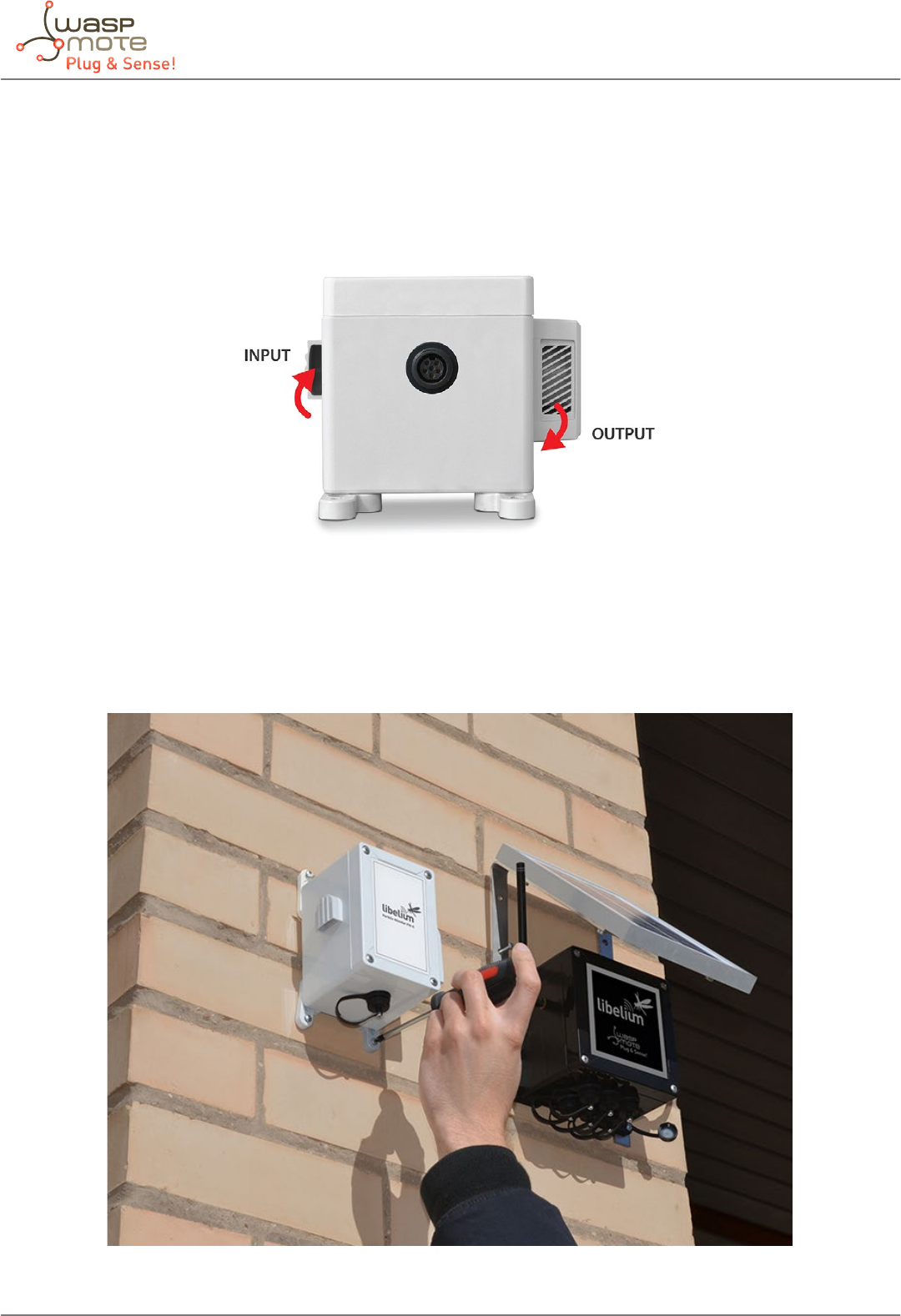
-50- v5.4
Waspmote Plug & Sense! - Sensors Guide
5.19.3. Installing the Sensor Probe
Libelium oers the OPC-N2 sensor inside a protective enclosure. The enclosure has special input and output accessories for
letting the air ow pass, but always keeping the rain or excesive dirt outside. Fixing accessories and one connection cord are
also provided. All the system is called the Particle Matter – Dust Sensor Probe.
Figure: Input and output accessories in the enclosure
The system comes with 4 mounting feet (T’s). The enclouse should be rmly xed to a wall with the provided screws, or xed to
a lampost or tree with 2 metal cable ties.
Figure: Fixing the Particle Matter – Dust Sensor Probe on a wall
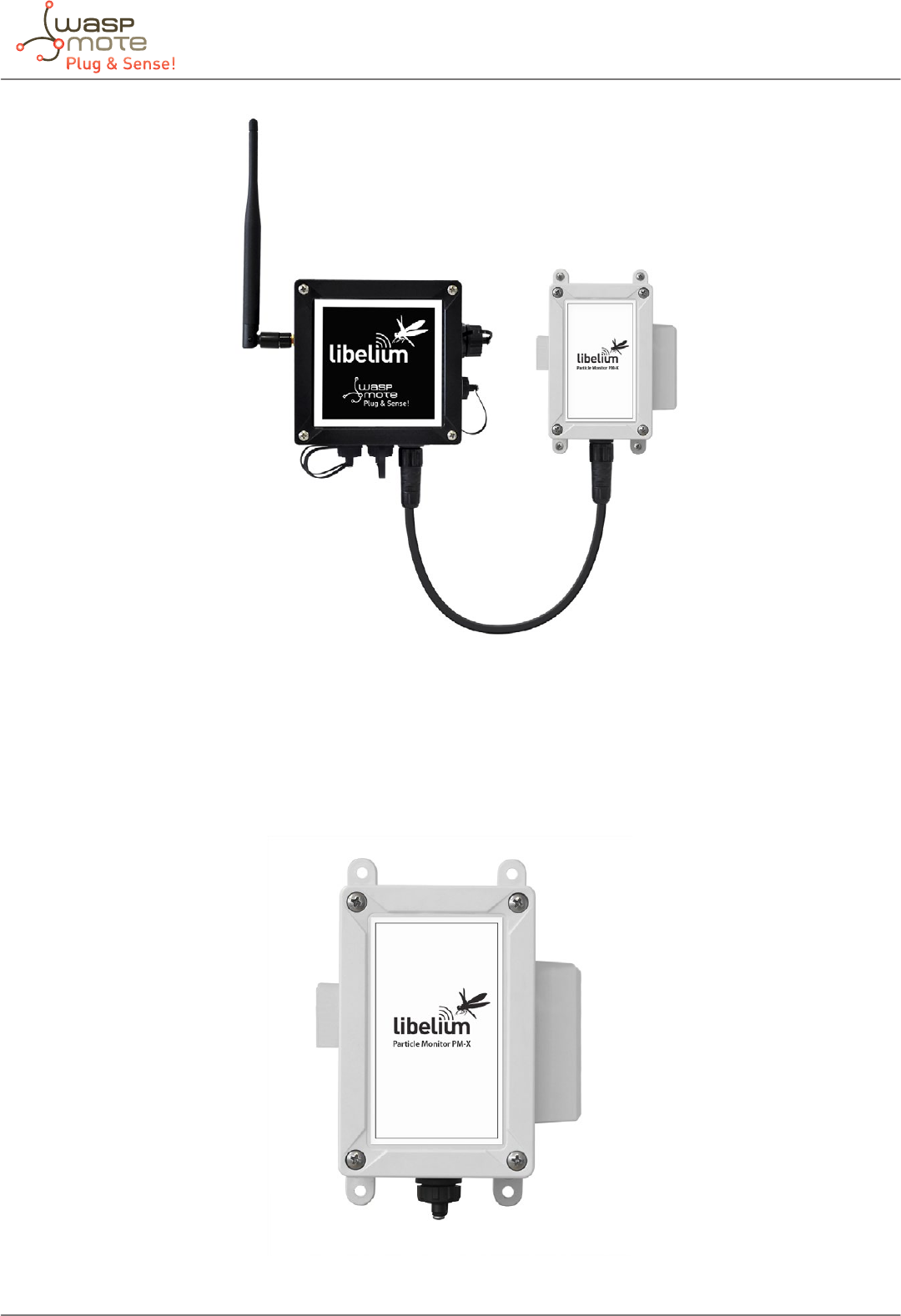
-51- v5.4
Waspmote Plug & Sense! - Sensors Guide
Figure: Connecting the Particle Matter – Dust Sensor Probe to Plug & Sense!
The installation of this Sensor Probe must be similar to any Plug & Sense! installation. Please read the “Installation” chapter in the
Plug & Sense! Technical Guide for further details.
Figure: Particle Matter – Dust Sensor Probe nally connected to Plug & Sense!
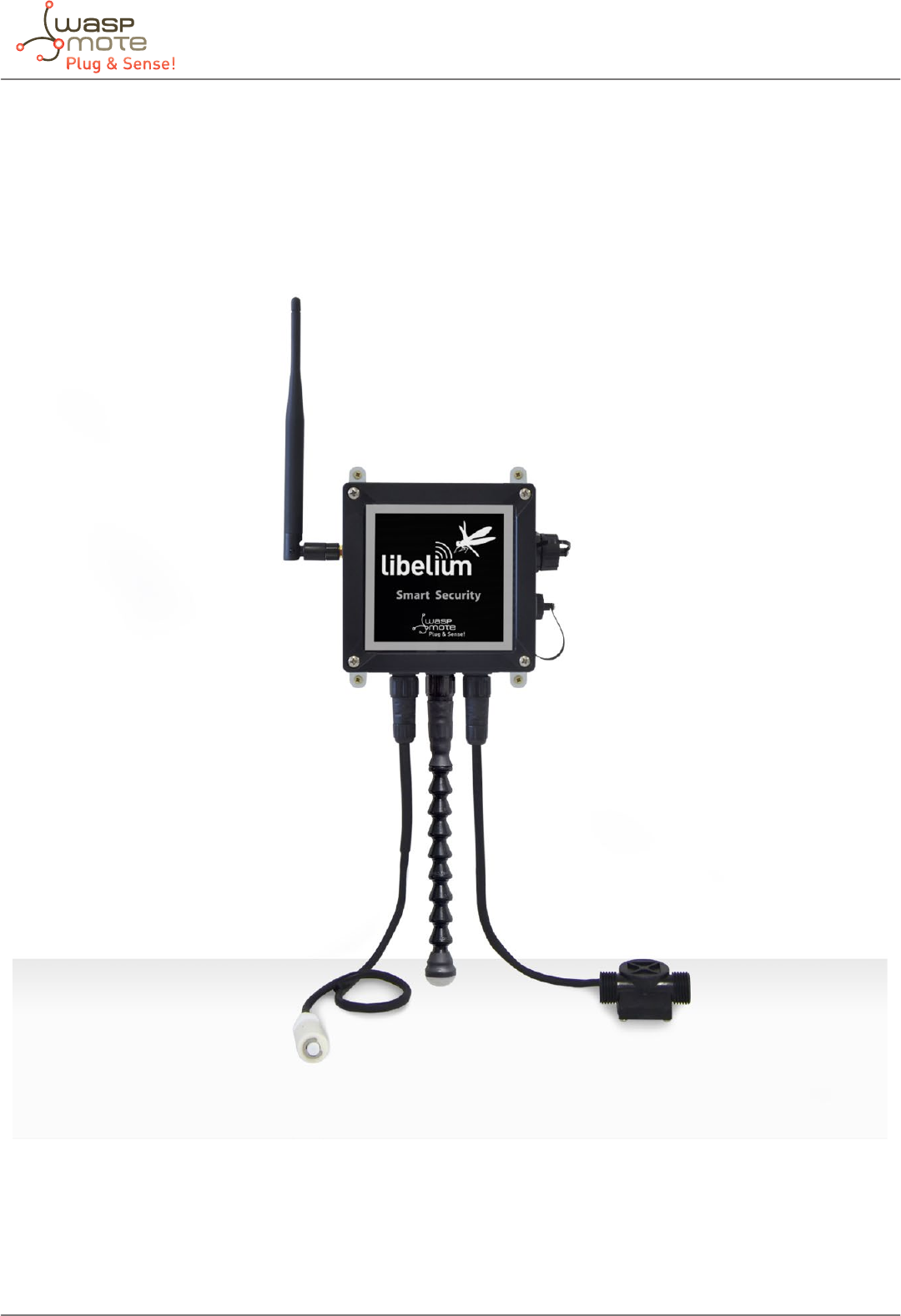
-52- v5.4
Waspmote Plug & Sense! - Sensors Guide
6. Smart Security
6.1. General description
The main applications for this Waspmote Plug & Sense! conguration are perimeter access control, liquid presence detection
and doors and windows openings.
Figure: Smart Security Waspmote Plug & Sense! Model
Note: The probes attached in this photo could not match the nal location. See next table for the correct conguration.
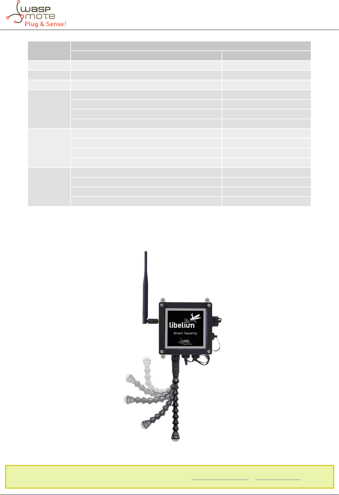
-53- v5.4
Waspmote Plug & Sense! - Sensors Guide
Sensor
Socket
Sensor probes allowed for each sensor socket
Parameter Reference
A Temperature + Humidity (Sensirion) 9247
B Liquid ow 9296, 9297, 9298
C Presence - PIR 9212
D
Luminosity (LDR) 9205
Liquid level 9239, 9240, 9242
Liquid presence 9243, 9295
Hall eect 9207
E
Luminosity (LDR) 9205
Liquid level 9239, 9240, 9242
Liquid presence 9243
Hall eect 9207
F
Luminosity (LDR) 9205
Liquid level 9239, 9240, 9242
Liquid presence 9243
Hall eect 9207
Figure: Sensor sockets conguration for Smart Security model
As we see in the gure below, thanks to the directionable probe, the presence sensor probe (PIR) may be placed in dierent
positions. The sensor can be focused directly to the point we want.
Figure: Congurations of the Presence sensor probe (PIR)
Note: For more technical information about each sensor probe go to the Development section in Libelium Website.
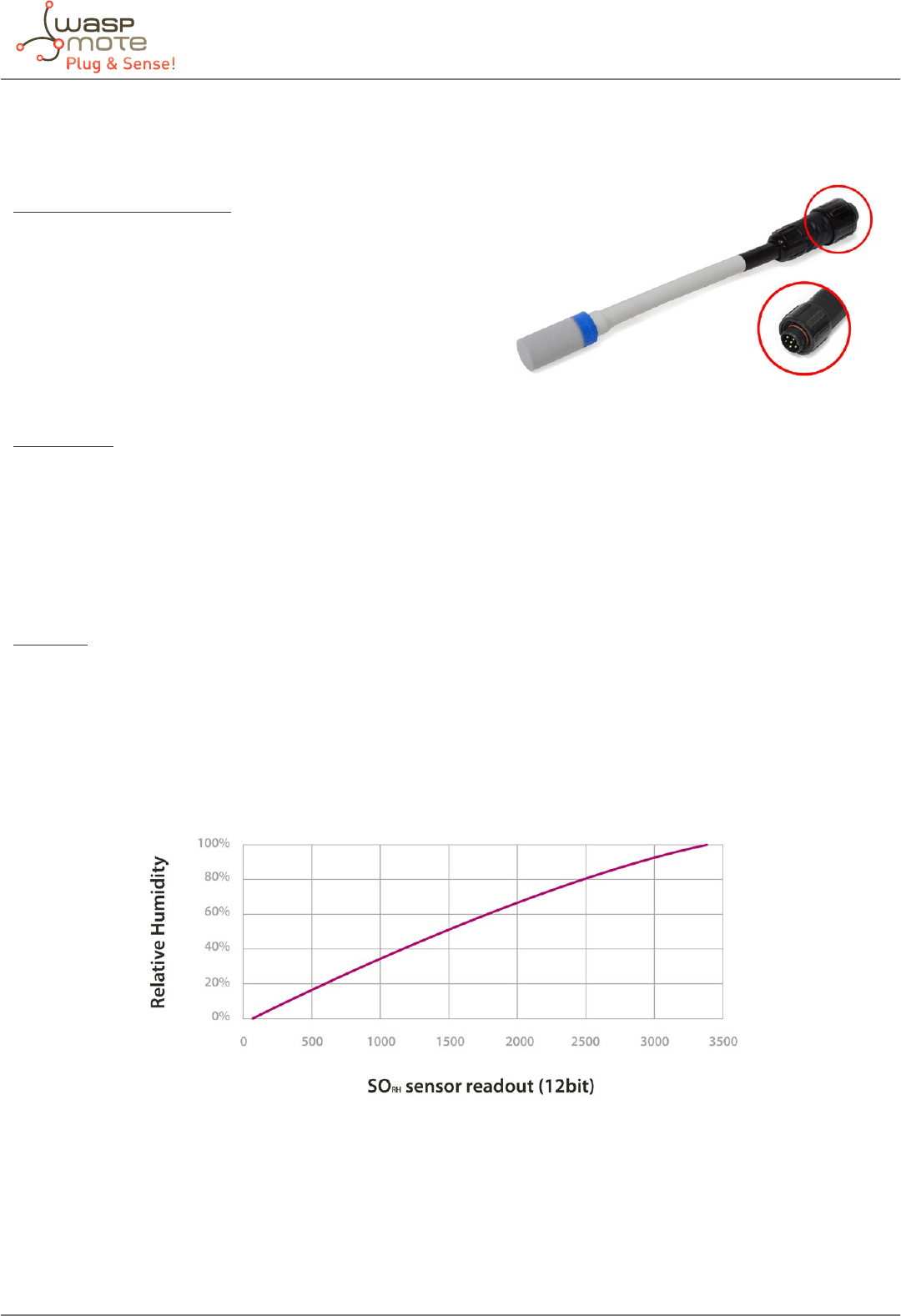
-54- v5.4
Waspmote Plug & Sense! - Sensors Guide
6.2. Temperature and Humidity sensor probe
Sensor specications (SHT75)
Power supply: 2.4 ~ 5.5V
Minimum consumption (sleep): 2µW
Consumption (measurement): 3mW
Average consumption: 90µW
Communication: Digital (two wire interface)
Storage temperature: 10 ~ 50ºC (0 ~ 80ºC maximum)
Storage humidity: 20 ~ 60%RH
Temperature:
Measurement range: -40ºC ~ +123.8ºC
Resolution: 0.04ºC (minimum), 0.01ºC (typical)
Accuracy: ±0.4ºC (range 0ºC ~ +70ºC), ±4ºC (range -40 ~ +125ºC)
Repeatability: ±0.1ºC
Response time (minimum): 5 seconds (63% of the response)
Response time (maximum): 30 seconds (63% of the response)
Humidity:
Measurement range: 0 ~ 100%RH
Resolution: 0.4%RH (minimum), 0.05%RH (typical)
Accuracy: ±1.8%RH
Repeatability: ±0.1%RH
Response time: 8 seconds
Figure: Graph of the sensor output with respect to relative humidity, taken from the Sensirion sensor’s data sheet
The SHT75 sensor by Sensirion incorporates a capacitive sensor for environmental relative humidity and a band gap sensor for
environmental temperature in the same package that permit to measure accurately both parameters. The sensor output is read
through two wires following a protocol similar to the I2C bus (Inter- Integrated Circuit Bus) implemented in the library of the
board, returning the temperature value in Celsius degree (ºC) and the humidity value in relative humidity percentage (%RH).
Figure: Image of the Temperature and Humidity sensor probe (SHT75)
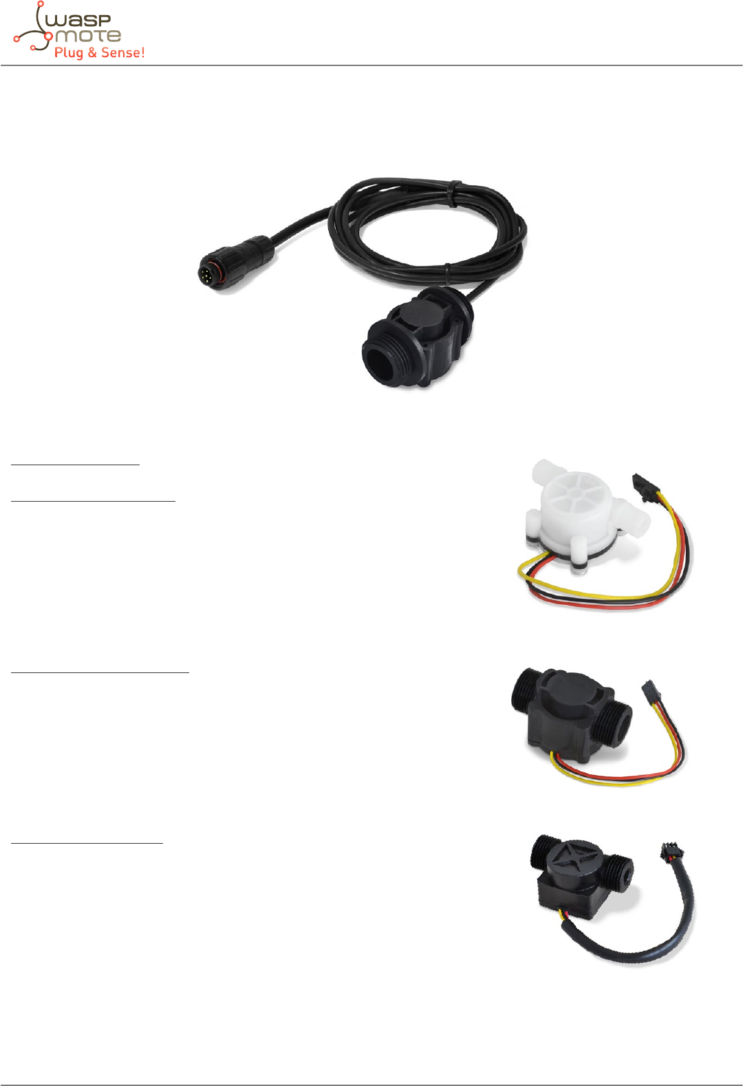
-55- v5.4
Waspmote Plug & Sense! - Sensors Guide
6.3. Liquid Flow sensor probes (FS100A, FS200A, FS300A, FS400,
YF-S401 and YF-G1)
Figure: Image of the Liquid Flow sensor probe (FS400)
Sensor specications
Water Flow Small, YF-S401:
Flow rate: 0.3 ~ 6L/Min
Working voltage: +3.3V ~ +24V
Working temperature: 0ºC ~ 80ºC
Pipe connection: 1/8”
Accuracy: ±3%
Max rated current: 15mA (DC 5V)
Water Flow Medium, FS300A:
Flow rate: 1 ~ 60L/Min
Working voltage: +5V ~ +24V (not suitable for +3.3V)
Working temperature: 0ºC ~ 80ºC
Pipe connection: 3/4’’
Accuracy: ±3%
Max rated current: 15mA (DC 5V)
Water Flow Large, YF-G1:
Flow rate: 1 ~ 100L/Min
Working voltage: +3.3V ~ +24V
Working temperature: 0ºC ~ 80ºC
Pipe connection: 1’’
Accuracy: ±3%
Max rated current: 15mA (DC 5V)
The liquid ow sensors output a signal that consists of a series of digital pulses whose frequency is proportional to the ow rate
of the liquid through the sensor. That digital signal, whose frequency is in the range between 0Hz and 100Hz, is directly read
through one of the digital input/output pins of the microcontroller.
Figure: Image of the YF-S401, Small Liquid Flow sensor
Figure: Image of the FS-300A, Medium Liquid Flow sensor
Figure: Image of the YF-G1, Large Liquid Flow sensor
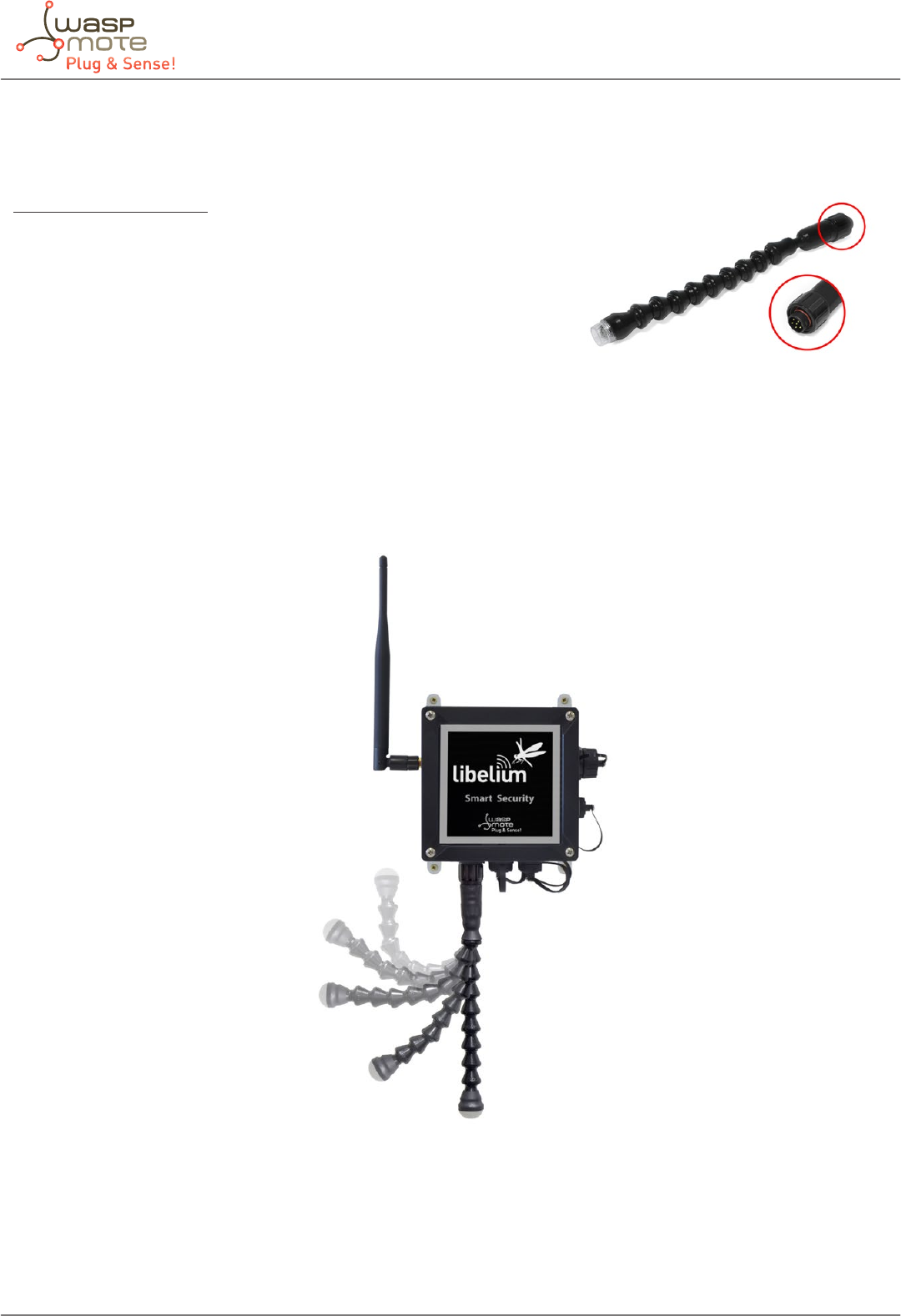
-56- v5.4
Waspmote Plug & Sense! - Sensors Guide
6.4. Presence sensor (PIR) probe
Sensor specications (PIR)
Height: 22mm
Diameter: 20.2mm
Consumption: 170μA
Range of detection: 12m
Circuit Stability Time: 30seconds
The PIR sensor (Passive Infra-Red) is a pyroelectric sensor mainly consisting of an infra-red receiver and a focusing lens that bases
its operation on the monitoring of the variations in the levels of reception of detected infra-reds, reecting this movement by
setting its output signal high. The 10μm spectrum corresponds to the radiation of heat from the majority of mammals as they
emit temperatures around 36°C.
Figure: Image of congurations of the Presence sensor probe (PIR)
As we see in the gure, the presence sensor probe (PIR) may be placed in dierent positions. The sensor can be focused directly
to the point we want.
Figure: Image of the Presence sensor probe (PIR)
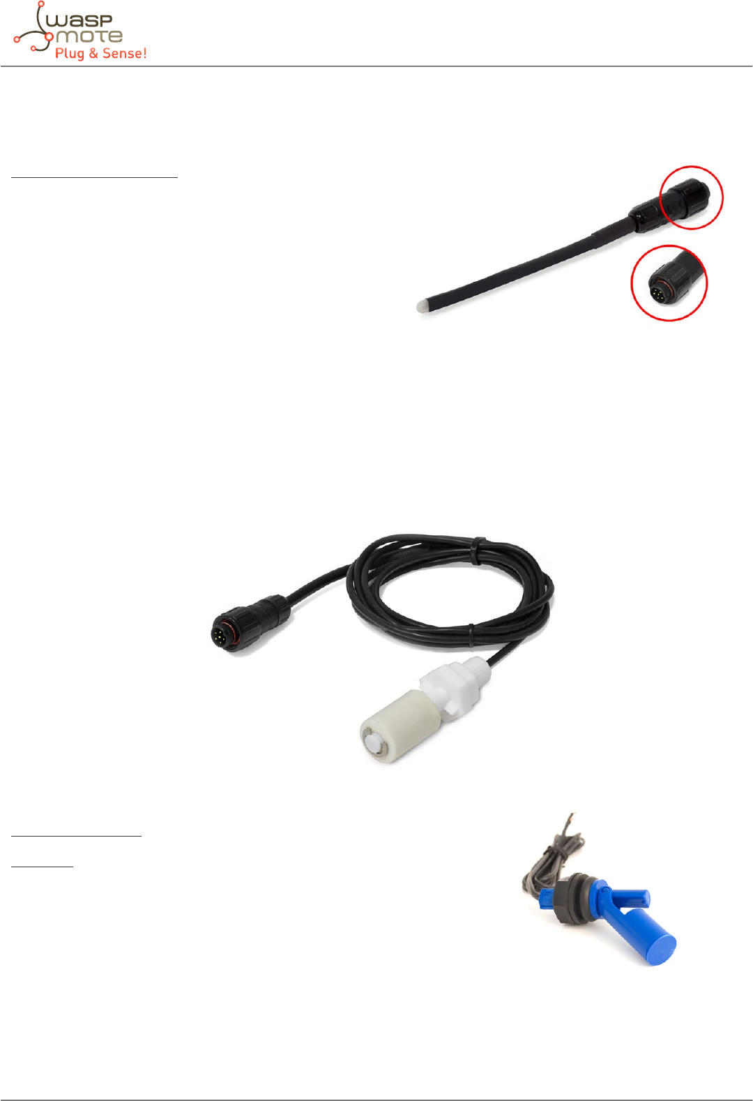
-57- v5.4
Waspmote Plug & Sense! - Sensors Guide
6.5. Luminosity sensor probe
Sensor specications (LDR)
Resistance in darkness: 20MΩ
Resistance in light (10lux): 5 ~ 20kΩ
Spectral range: 400 ~ 700nm
Operating temperature: -30ºC ~ +75ºC
This is a resistive sensor whose conductivity varies depending on the intensity of light received on its photosensitive part.
The measurable spectral range (400nm – 700nm) coincides with the human visible spectrum so it can be used to detect light/
darkness in the same way that a human eye would detect it.
6.6. Liquid Level sensor probe
Figure: Image of the Liquid Level sensor probe (PTFA1103)
Sensor specications
PTFA3415
Measurement Level: Horizontal
Liquids: Water
Material (box): Propylene
Material (oat): Propylene
Operating Temperature: -10ºC ~ +80ºC
Figure: Image of the Luminosity sensor probe (LDR)
Figure: Image of the PTFA3415 sensor
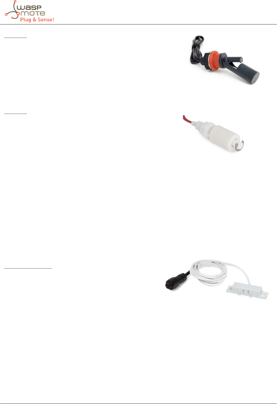
-58- v5.4
Waspmote Plug & Sense! - Sensors Guide
PTFA0100
Measurement Level: Horizontal
Liquids: Heavy oils and combustibles
Material (box): Polyamide
Material (oat): Polyamide
Operating temperature: -10ºC ~ +80ºC
PTFA1103
Measurement Level: Vertical
Liquids: Water
Material (box): Propylene
Material (oat): Propylene
Operating temperature: -10ºC ~ +80ºC
There are three liquid level sensors whose operation is based on the status of a switch which can be opened and closed
(depending on its placing in the container) as the level of liquid moves the oat at its end. The main dierences between the
three sensors, regarding its use in Waspmote, are to be found in their process for placing them in the container (horizontal
in the case of the PTFA3415 and PTFA0100 sensors, vertical for the PTFA1103 sensor) and in the material they are made of
(the PTFA1103 and PTFA3415 sensors recommended for edible liquids and certain acids and the PTFA0100 for heavy oils and
combustibles, more specic information can be found in the sensors’ manual).
6.7. Liquid Presence sensor probe (Point)
Sensor specications
Maximum Switching Voltage: 100V
Operating temperature: +5ºC ~ +80ºC
Detectable liquids: Water
This sensor bases its operation on the variation in resistance between its two contacts in the presence of liquid to commute
a switch reed from open to closed, commuting to open again when the liquid disappears (take care when it is used to detect
liquids of high viscosity which may remain between the terminals blocking its drainage and preventing it from re-opening).
Figure: Image of the PTFA0100 sensor
Figure: Image of the PTFA1103 sensor
Figure: Image of the Liquid Presence sensor probe (Point)
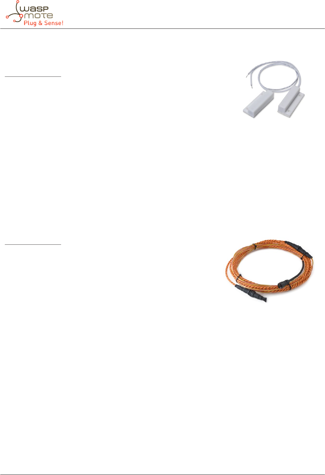
-59- v5.4
Waspmote Plug & Sense! - Sensors Guide
6.8. Hall Eect sensor probe
Sensor specications
Length: 64mm
Width: 19mm
Thickness: 13mm
Maximum contact resistance (closed): 200mΩ
Minimum contact resistance (open): 100GΩ
This is a magnetic sensor based on the Hall eect. The sensor’s switch remains closed in the presence of a magnetic eld,
opening up in its absence. Together with its complementary magnet it can be used in applications of monitoring proximity or
opening mechanisms.
6.9. Liquid Presence sensor probe (Line)
Sensor specications
Lenght: 5 meters sensor + 2 meters jumper wire
Material: PE + alloy lend
Weight: 18g/meter
Pull force limit: 60kg
Cable diameter: 5,5mm
Core resistance: 3ohm/100meters
Maximum exposed temperature: 75ºC
Detectable liquids: Water
This sensor detects conductive liquids anywhere along its length. After it is installed, once the cable senses the leakage of
liquids, it will triggers an alarm. The sensor cable can detects the leakage of water.
Installation of this sensor should be in a safe place, far away from high magnetic elds and damp environment. In the installation,
let sensor cable keep away from sharp material to avoid scung the sensor.
Figure: Image of the Hall Eect sensor probe
Figure: Image of the Liquid Presence sensor probe (Line)
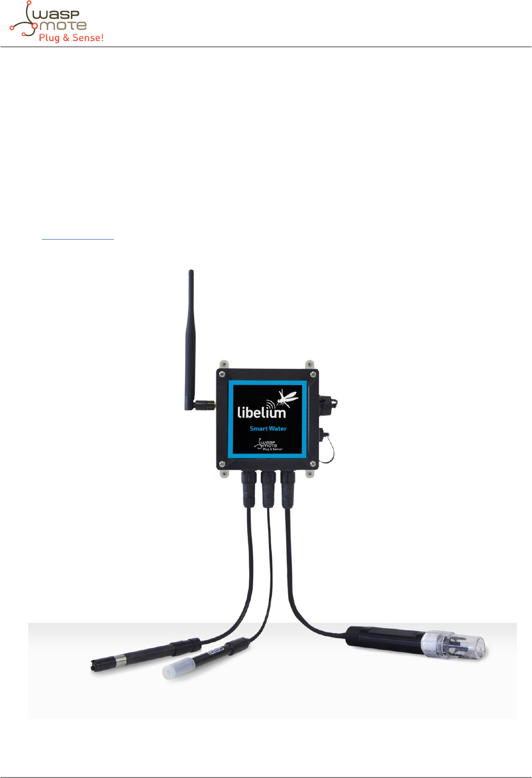
-60- v5.4
Waspmote Plug & Sense! - Sensors Guide
7. Smart Water
7.1. General description
The Smart Water model has been conceived to facilitate the remote monitoring of the most relevant parameters related to
water quality. With this platform you can measure more than 6 parameters, including the most relevant for water control such
as dissolved oxygen, oxidation-reduction potential, pH, conductivity and temperature. An extremely accurate turbidity sensor
has been integrated as well.
The Smart Water Ions line is complementary for these kinds of projects, enabling the control of concentration of ions like Calcium
(Ca2+), Fluoride (F-), Fluoroborate (BF4
-), Nitrate (NO3
-), Bromide (Br-), Chloride (Cl-), Cupric (Cu2+), Iodide (I-), Lead (Pb2+), Silver (Ag+)
and pH. Take a look to the Smart Water Ions line in the next section.
Refer to Libelium website for more information.
Figure: Smart Water Waspmote Plug & Sense! model

-61- v5.4
Waspmote Plug & Sense! - Sensors Guide
Sensor sockets are congured as shown in the gure below.
Sensor
Socket
Sensor probes allowed for each sensor socket
Parameter Reference
BpH 9328
Oxidation-Reduction Potential (ORP) 9329
CpH 9328
Oxidation-Reduction Potential (ORP) 9329
DSoil/Water Temperature 9255 (included by default)
E Dissolved Oxygen (DO) 9327
FConductivity 9326
Turbidity 9353
Figure: Sensor sockets conguration for Smart Water model
Note: For more technical information about each sensor probe go to the Development section in Libelium Website.
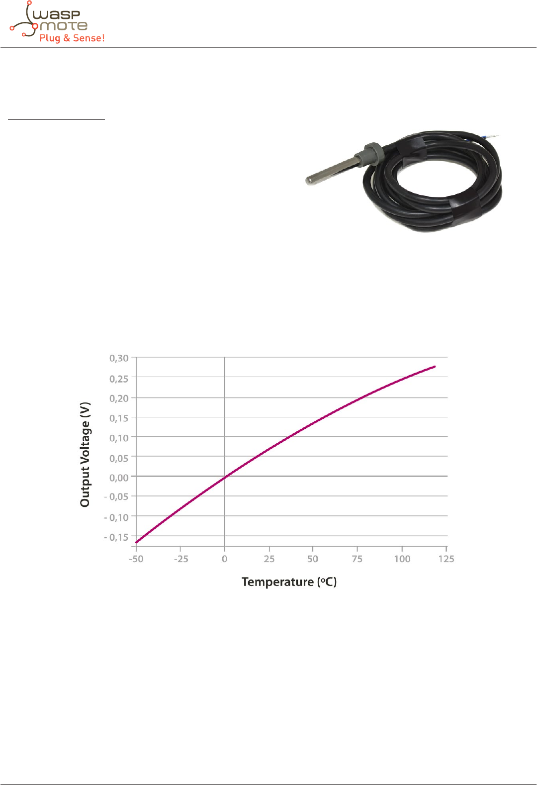
-62- v5.4
Waspmote Plug & Sense! - Sensors Guide
7.2. Soil/Water Temperature sensor (Pt1000) probe
Sensor specications
Measurement range: 0 ~ 100ºC
Accuracy: DIN EN 60751
Resistance (0ºC): 1000Ω
Diameter: 6mm
Length: 40mm
Cable: 2m
The resistance of the Pt1000 sensor varies between approximately 920Ω and 1200Ω in the range considered useful in agriculture
applications (-20 ~ 50ºC approximately), which results in too low variations of voltage at signicant changes of temperature for
the resolution of the Waspmote’s analog-to-digital converter. The temperature value is returned in Celsius degree (ºC).
Figure: Output voltage of the PT1000 sensor with respect to temperature
Figure: Image of the Soil/Water Temperature sensor probe
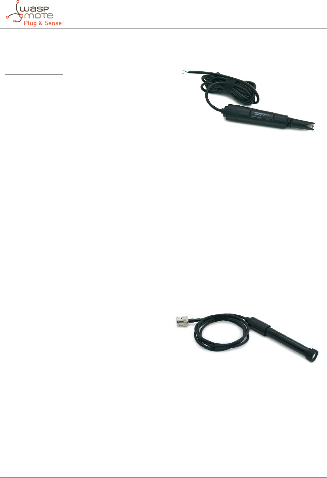
-63- v5.4
Waspmote Plug & Sense! - Sensors Guide
7.3. Conductivity sensor probe
Sensor specications
Sensor type: Two electrodes sensor
Electrode material: Platinum
Conductivity cell constant: 1 ± 0.2 cm-1
The conductivity sensor is a two-pole cell whose resistance varies in function of the conductivity of the liquid it is immersed in.
That conductivity will be proportional to the conductance of the sensor (the inverse of its resistance), multiplied by the constant
cell, in the case of the Libelium sensor around 1cm-1, leading to a value in Siemens per centimeter (S/cm). For an accurate
measurement, please take a look at section “Calibration Procedure” in the Smart Water Technical Guide, where the calibration
procedure is detailed.
To power the conductivity sensor an alternating current circuit has been installed in order to avoid the polarization of the
platinum electrodes. This current’s frequency can be set at four dierent values (100Hz, 1kHz, 10kHz and 100kHz) to adapt the
measurement to the optimal operation point, which will be a function of the conductivity of the liquid and the characteristics
of the sensor. For the sensor integrated in the Smart Water board, it is recommended to use a 100Hz frequency of conductivities
lower than 50μS/cm, 1kHz between 50μS/cm and 5mS/cm, 10kHz between 5mS/cm and 500mS/cm and 100kHz for conductivities
higher than 500mS/cm.
7.4. Dissolved Oxygen sensor probe
Sensor specications
Sensor type: Galvanic cell
Range: 0~20mg/L
Accuracy: ±2%
Maximum operation temperature: 50ºC
Saturation output: 33mV ±9mV
Pressure: 0~100psig (7.5Bar)
Calibration: Single point in air
Response Time: After equilibration, 2 minutes for 2mV
The galvanic cell provides an output voltage proportional to the concentration of dissolved oxygen in the solution under
measurement without the need of a supply voltage. This value is amplied to obtain a better resolution and measured with the
analog-to-digital converter placed on the Smart Water board.
This sensor should be calibrated with the calibration solution for more accurate measurements.
Figure: Image of the Conductivity sensor probe
Figure: Image of the Dissolved Oxygen sensor probe
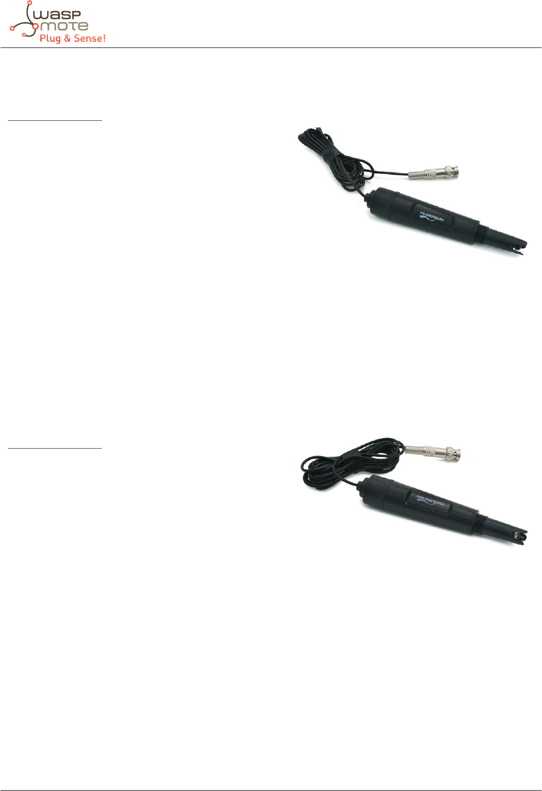
-64- v5.4
Waspmote Plug & Sense! - Sensors Guide
7.5. pH sensor probe
Sensor specications
Sensor type: Combination electrode
Measurement range: 0~14pH
Temperature of operation: 0~80ºC
Zero electric potential: 7±0.25p
Response time: <1min
Internal resistance: ≤250MΩ
Repeatability: 0.017
PTS: >98.5
Noise: <0.5mV
Alkali error: 15mV
Reader accuracy: up to 0.01 (in function of calibration)
The pH sensor integrated in the Smart Water board is a combination electrode that provides a voltage proportional to the pH of
the solution, corresponding the pH 7 with the voltage reference of 2.048V of the circuit, with an uncertainty of ±0.25pH. To get
an accurate value from these sensors it is necessary both to carry out a calibration and to compensate the output of the sensor
for the temperature variation from that of the calibration moment.
7.6. Oxidation-reduction potential sensor probe
Sensor specications
Sensor type: Combination electrode
Electric Potential: 245~270mV
Reference impedance: 10kΩ
Stability: ±8mV/24h
Like the pH sensor, the ORP probe is a combination electrode whose output voltage is equivalent to the potential of the
solution, so it will share the connection sockets with that sensor. The output of the circuitry to which it is connected is directly
read from the analog-to-digital converter of the Smart Water sensor board, being the 2.048V reference subtracted to obtain the
actual oxidation-reduction potential in volts (in this case, since this parameter is directly a voltage it is not necessary to call a
conversion function).
This sensor should be calibrated with the calibration solution for more accurate measurements.
Figure: Image of the pH sensor probe
Figure: Image of the Oxidation-reduction potential sensor probe

-65- v5.4
Waspmote Plug & Sense! - Sensors Guide
7.7. Turbidity sensor probe
Specications
Sensor type: IR optical sensor with optical bre
Measurement range: 0-4000 NTU
Accuracy: 5% (around 1 NTU in the lower scale)
Robust and waterproof : IP68
Digital output: Modbus RS-485
Power consumption : 820 μA
Power supply: 5 V
Stocking temperature: -10 to +60 °C
Material: PVC, Quartz, PMMA, Nickel-plated brass
This sensor is available for Waspmote “OEM” line and for Plug & Sense! line too.
In the OEM version, the sensor comes as a kit because it needs additional equipment (see list below). The user will connect the
sensor to a special RS-485 module.
On the other hand, for the Plug & Sense! version, everything comes connected inside the node and the user just needs to
plug the probe to the F bottom socket. Be informed that Plug & Sense! nodes capable of measuring turbidity are produced on
demand (so standard Smart Water Plug & Sense! nodes cannot integrate the turbidity sensor).
The turbidity sensor is extremely sensitive and the user must treat it with especial care in all situations (laboratory tests,
development, installation, etc). The sensor must be installed in a solid way and protected from any impact.
Refer to Libelium website for more information.
7.7.1. Turbidity: the parameter
Turbidity is the haziness of a uid caused by individual solid particles that are generally invisible to the naked eye. The
measurement of turbidity is a key test of water quality. Nephelometers, or nephelometric turbidimeters, measure the light
scattered at an angle of 90° by one detector from the incident light beam generated by an incandescent light bulb. Readings
are reported in Nephelometric Turbidity Units, or NTUs. NTU has been the traditional reporting unit for turbidity and is still
recognized by some as the “universal” unit of measure, regardless of the technology used.
The measurement of the turbidity is important in the next scenarios:
• Urban waste water treatment (inlet / outlet controls)
• Sanitation network
• Industrial euent treatment
• Surface water monitoring
• Drinking water
7.7.2. Measurement process
The Turbidity sensor, is a digital sensor and must be used with the RS-485 module in combination with the Modbus library. The
use of the Smart Water Board is no necessary with this sensor, but is very interesting in water monitoring applications. In fact,
the Turbidity sensor can be used in combination with any Sensor Board. The RS-485 standard allows the use of longer wires, and
thanks to the use of dierential signaling it resists the electromagnetic interferences.
Figure: Turbidity sensor

-66- v5.4
Waspmote Plug & Sense! - Sensors Guide
Up now, the measurement of the turbidity was not easy and must be done by qualied personal, collecting samples for
laboratory exams. Libelium’s sensor permits automatic metering. According to the sensor’s manufacturer specications, the
measurement of the turbidity must be done in a light tight pot, the sensor must be in a xed position and the water container
must be clean or the measure may be wrong.
The accuracy of this sensor is about 1 NTU. The WHO (World Health Organization), establishes that the turbidity of drinking
water shouldn’t be more than 5 NTU, and should ideally be below 1 NTU. This sensor can be used to determine if the turbidity
level of the water is under acceptable levels for consumption, but can’t be used to determine the exact value of turbidity,
because this values is measured in specialized laboratories using special equipment.
The sensor takes some time to get stable values. The correct way to measure the turbidity using this sensor is to take samples
for approximately 60-90 seconds and then make the mean between the measured values. Libelium, provides the necessary
examples included in the Waspmote IDE.
The Turbidity sensor is calibrated in Libelium. Basically, Libelium performs measurements with a range of normalized chemical
solutions, which have a known and exact NTU value. This allows us to generate calibration data which the user will use to
improve the accuracy of the sensor.
In the code below a basic example for reading this sensor connected to the RS-485 board:
{
// Start a new measure
turbiditySensor.readTurbidity();
// Get the Turbidity Measure
oatturbidity=turbiditySensor.getTurbidity();
}
You can nd a complete example code for reading the turbidity sensor in the following link:
http://www.libelium.com/development/waspmote/examples/sw-07-turbidity-sensor-reading
In the image below you can see the necessary material for measuring turbidity with Waspmote. This OEM kit includes:
• The Turbidity sensor, with DB9 connector to connect directly to the RS-485 module
• An especial Waspmote, able to drive the SPI bus to SOCKET0
• The RS-485 module, who must be connected in the SOCKET0
• The expansion board, for connecting wireless modules in SOCKET1
• Two stackable headers, for connecting sensor boards to Waspmote
• Document with laboratory calibration data
Note: in Plug & Sense! version, the user receives items 2, 3, 4 and 5 inside the node. It is just needed to connect the sensor probe to
the F socket.
Note: The RS-485 module included in this kit is a special version ready to be used with the Turbidity sensor, and includes the
necessary hardware for supplying the sensor from the DB9 connector. The standard version of the RS-485 module can’t be used
with this sensor.
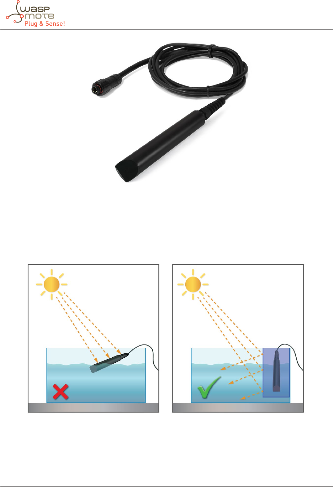
-67- v5.4
Waspmote Plug & Sense! - Sensors Guide
Figure: The necessary material for connecting the Turbidity sensor (Plug & Sense! version)
The placement of the sensor is important to get a correct turbidity measurement. The sensor must be placed in a xed position,
you must make sure that light cannot interfere with the optical part of the sensor. Otherwise, sun or light can aect the values.
It is necessary a minimum distance, about 3-4 centimeters, between the sensor and the bottom of the beaker.
Figure: Turbidity sensor image wrongly and correctly placed
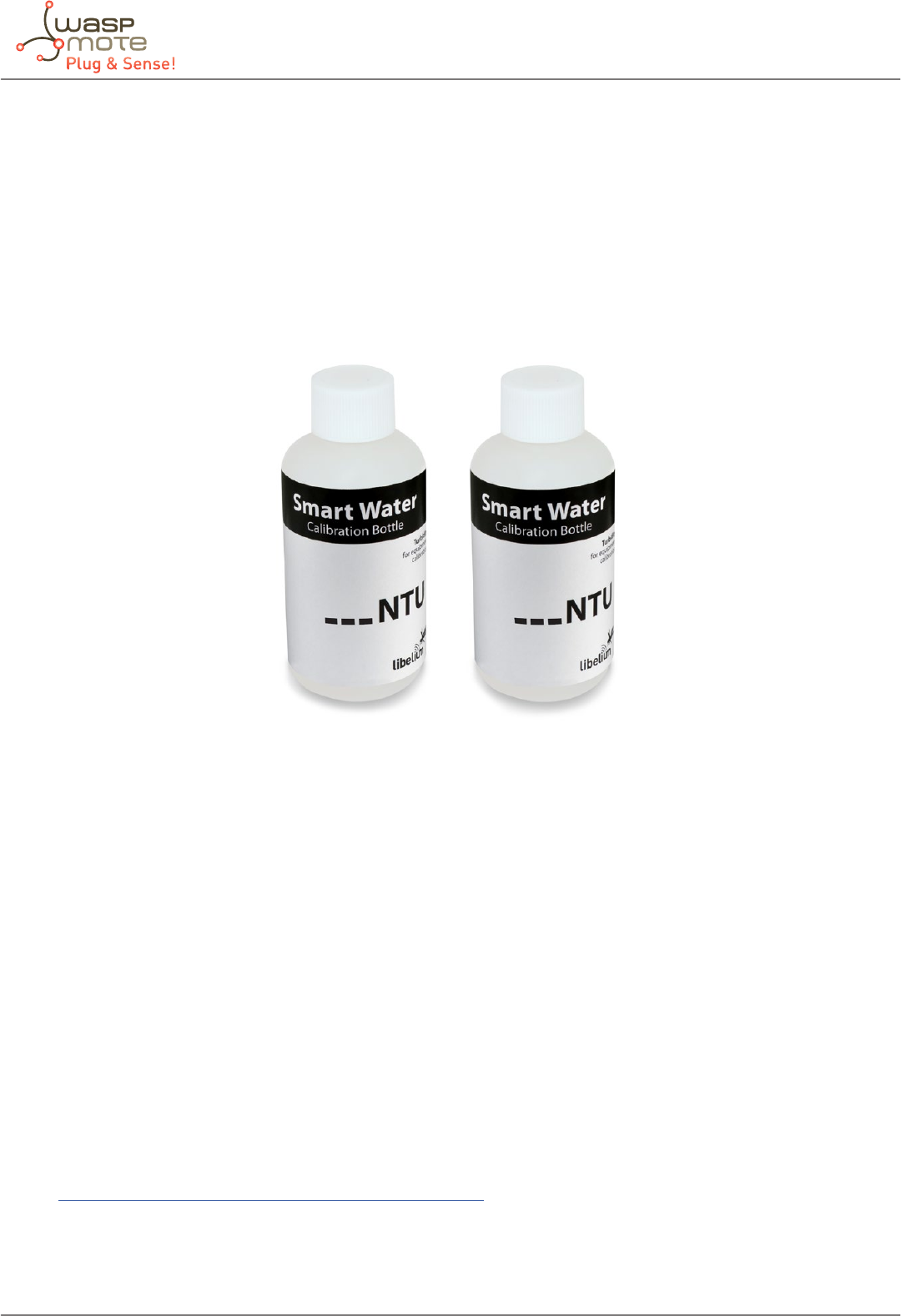
-68- v5.4
Waspmote Plug & Sense! - Sensors Guide
7.7.3. Calibration procedure
Important: Libelium provides this sensor calibrated, but a periodic recalibration of the sensors is highly advisable (every 6
months approximately) in order to maintain an accurate measurement along time. The good recalibration process of the sensor
is responsibility of the user. Libelium provides standard calibration solutions for some turbidity values; these solutions are
optional but highly recommended.
Libelium can provide 2 dierent turbidity calibration kits, each one is composed of 2 solutions which will provide 2 reference
points:
• Low turbidity: about 0-10 NTU
• High Turbidity: about 10-40 NTU
Figure: Turbidity calibration kit
1. Turn on the Waspmote with the Turbidity sensor connected. Upload the “Turbidity sensor calibration” code to Waspmote.
Make sure that the data from the sensor is being received in a PC through the USB.
2. Pour the calibration solution in a beaker. The baker must be clean and according to the manufacturer specications,
the measurement of the turbidity must be done in a light tight pot, the sensor must be in a xed position and the water
container must be clean or the measure may be wrong.
3. Introduce the sensor into the calibration solution, making sure it stays immersed without contact with the beaker walls
or bottom, and wait for the code’s output value for stabilize. You have to annotate the value of the used solution and the
returned values from the sensor (e.g. [25, 24.1]).
4. Remove the sensor, and clean it properly before continuing.
5. Repeat steps 2, 3 and 4, depending on the number of solutions you want to recalibrate with.
6. Introduce the measured values in the Waspmote code or in the data processing in the receiver. These values will be
introduced manually in the code by the user. The new calibration values can replace the old ones.
In the Waspmote Development section you can nd complete examples about using this board.
Go to: http://www.libelium.com/development/waspmote/examples
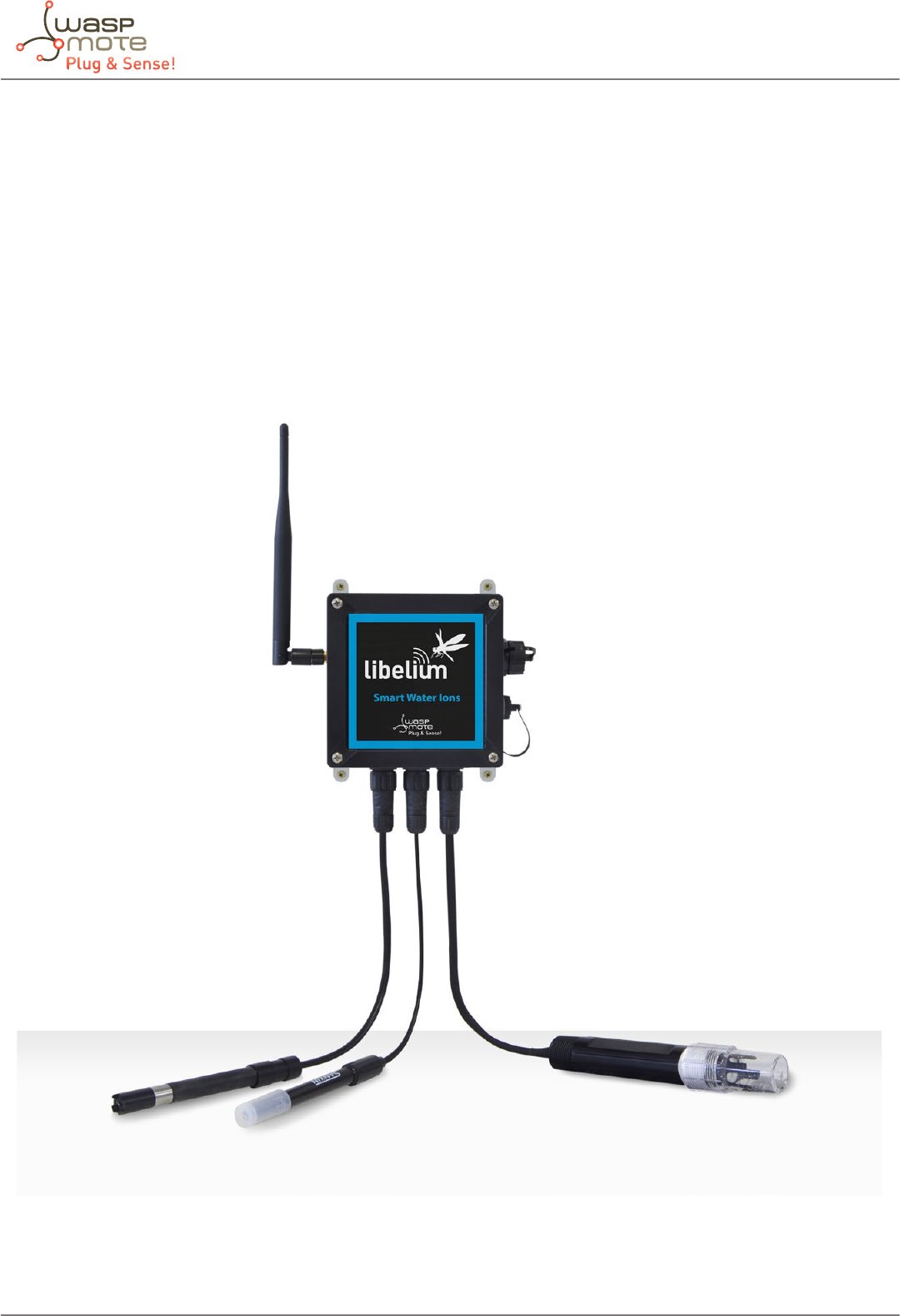
-69- v5.4
Waspmote Plug & Sense! - Sensors Guide
8. Smart Water Ions
8.1. General description
The Smart Water Ions models specialize in the measurement of ions concentration for drinking water quality control, agriculture
water monitoring, swimming pools or waste water treatment.
The Smart Water line is complementary for these kinds of projects, enabling the control of parameters like turbidity, conductivity,
oxidation-reduction potential and dissolved oxygen. Take a look to the Smart Water line in the previous section. Refer to Libelium
website for more information.
There are 2 variants for Smart Water Ions: Single and Double. This is related to the type of ion sensor that each variant can
integrate. Next section describes each conguration in detail.
Figure: Smart Water Ions Waspmote Plug & Sense! model

-70- v5.4
Waspmote Plug & Sense! - Sensors Guide
8.1.1. Single
This variant includes a Single Junction Reference Probe, so it can read all the single type ion sensors.
Sensor sockets are congured as shown in the table below.
Sensor
Socket
Sensor probes allowed for each sensor socket
Parameter Reference
A
Calcium Ion (Ca2+) 9352
Fluoride Ion (F-) 9353
Fluoroborate Ion (BF4-) 9354
Nitrate Ion (NO3
-) 9355
pH (for Smart Water Ions) 9363
B
Calcium Ion (Ca2+) 9352
Fluoride Ion (F-) 9353
Fluoroborate Ion (BF4
-) 9354
Nitrate Ion (NO3
-) 9355
pH (for Smart Water Ions) 9363
C
Calcium Ion (Ca2+) 9352
Fluoride Ion (F-) 9353
Fluoroborate Ion (BF4
-) 9354
Nitrate Ion (NO3
-) 9355
pH (for Smart Water Ions) 9363
D
Calcium Ion (Ca2+) 9352
Fluoride Ion (F-) 9353
Fluoroborate Ion (BF4
-) 9354
Nitrate Ion (NO3
-) 9355
pH (for Smart Water Ions) 9363
E Single Junction Reference 9350 (included by default)
FSoil/Water Temperature 9255 (included by default)
Figure: Sensor sockets conguration for Smart Water Ions model, single variant
Note: For more technical information about each sensor probe go to the Development section in Libelium website.

-71- v5.4
Waspmote Plug & Sense! - Sensors Guide
8.1.2. Double
This variant includes a Double Junction Reference Probe, so it can read all the double type ion sensors.
Sensor sockets are congured as shown in the table below.
Sensor
Socket
Sensor probes allowed for each sensor socket
Parameter Reference
A
Bromide Ion (Br-) 9356
Chloride Ion (Cl-) 9357
Cupric Ion (Cu2+) 9358
Iodide Ion (I-) 9360
Lead Ion (Pb2+) 9361
Silver Ion (Ag+) 9362
pH (for Smart Water Ions) 9363
B
Bromide Ion (Br-) 9356
Chloride Ion (Cl-) 9357
Cupric Ion (Cu2+) 9358
Iodide Ion (I-) 9360
Lead Ion (Pb2+) 9361
Silver Ion (Ag+) 9362
pH (for Smart Water Ions) 9363
C
Bromide Ion (Br-) 9356
Chloride Ion (Cl-) 9357
Cupric Ion (Cu2+) 9358
Iodide Ion (I-) 9360
Lead Ion (Pb2+) 9361
Silver Ion (Ag+) 9362
pH (for Smart Water Ions) 9363
D
Bromide Ion (Br-) 9356
Chloride Ion (Cl-) 9357
Cupric Ion (Cu2+) 9358
Iodide Ion (I-) 9360
Lead Ion (Pb2+) 9361
Silver Ions (Ag+) 9362
pH (for Smart Water Ions) 9363
EDouble Junction Reference 9351 (included by default)
FSoil/Water Temperature 9255 (included by default)
Figure: Sensor sockets conguration for Smart Water Ions model, double variant
Note: For more technical information about each sensor probe go to the Development section in Libelium website.
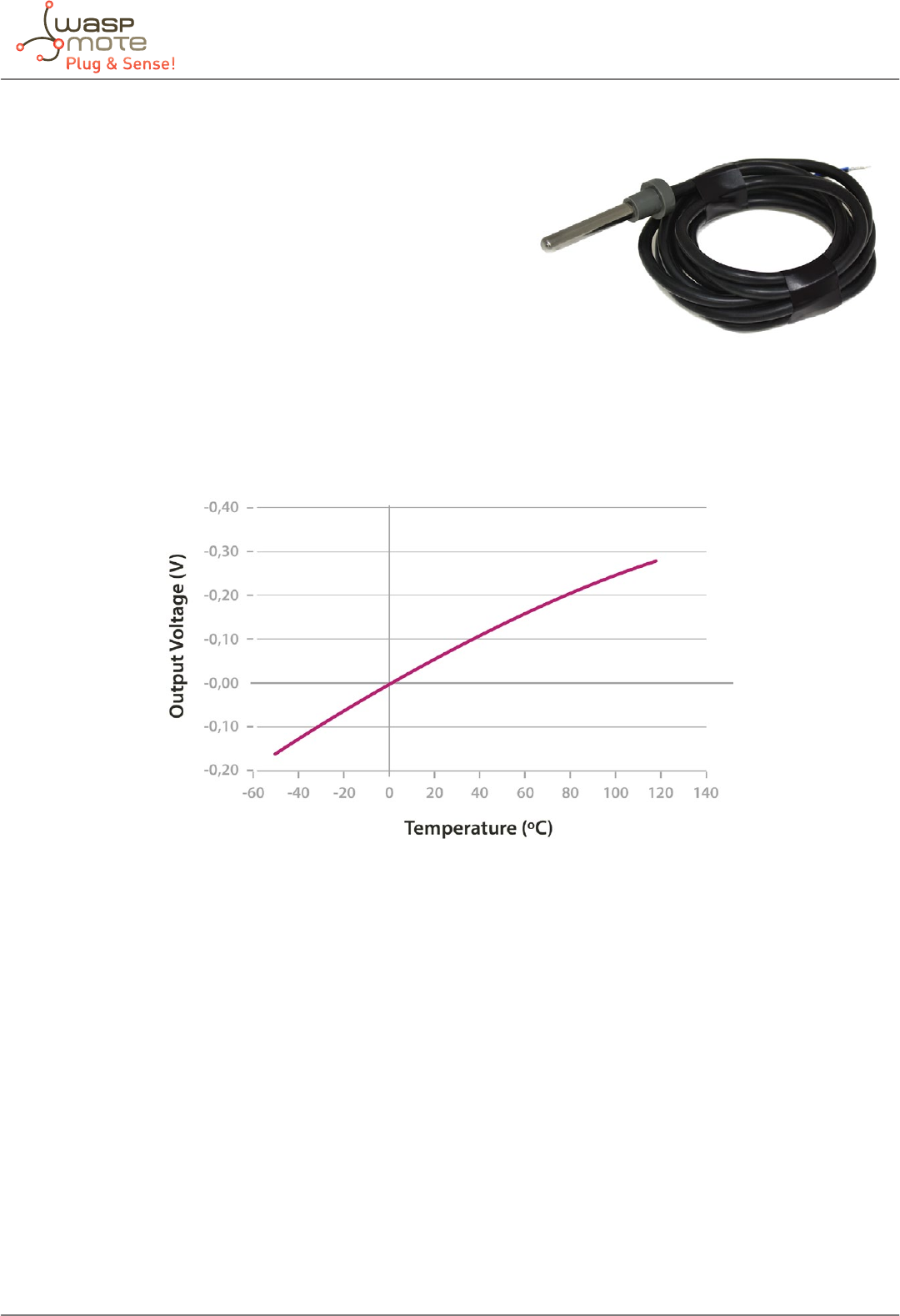
-72- v5.4
Waspmote Plug & Sense! - Sensors Guide
8.2. Soil/Water Temperature sensor (Pt-1000)
•Measurement range: 0 ~ 100 ºC
•Accuracy: DIN EN 60751
•Resistance (0 ºC): 1000 Ω
•Diameter: 6 mm
•Length: 40 mm
•Cable: 2 m
The resistance of the Pt1000 sensor varies between approximately 920Ω and 1200Ω in the range considered useful in agriculture
applications (-20 ~ 50ºC approximately), which results in too low variations of voltage at signicant changes of temperature for
the resolution of the Waspmote’s analog-to-digital converter. The temperature value is returned in Celsius degree (ºC).
Figure: Output voltage of the PT1000 sensor with respect to temperature
Figure: Soil/Water Temperature (Pt-1000) Sensor

-73- v5.4
Waspmote Plug & Sense! - Sensors Guide
8.3. Reference probes
A reference electrode is an electrode which has a stable and well-known electrode potential. Reference electrodes are critical to
acquiring good electrochemical data. Drift in the reference electrode potential can cause quantitative and qualitative errors in
data collection and analysis beyond simple inaccuracies in the measured potential.
Plug & Sense! Smart Water Ions line has two dierent variants, according to the Reference Probes each Plug & Sense! Includes:
• The Single variant always include a Single Junction Reference.
• The Double variant always include a Double Junction Reference.
The next sensors must be used with the Single Junction Reference Probe:
• Calcium Ion (Ca2+) Sensor Probe
• Fluoride Ion (F-) Sensor Probe
• Fluoroborate Ion (BF4
-) Sensor Probe
• Nitrate Ion (NO3
-) Sensor Probe
The next sensors must be used with the Double Junction Reference Probe:
• Bromide Ion (Br-) Sensor Probe
• Chloride Ion (Cl-) Sensor Probe
• Cupric Ion (Cu2+) Sensor Probe
• Iodide Ion (I-) Sensor Probe
• Lead Ion (Pb2+) Sensor Probe
• Silver Ion (Ag+) Sensor Probe
The pH (for Smart Water Ions) Sensor must be always used with the Single or the Double Reference Probe.
The Soil/Water Temperature Sensor is the only sensor in this board which does not need any Reference Probe.
One Reference Probe must always be connected in the corresponding socket marked as REFERENCE in the Smart Water Ions
Sensor Board. Only one Reference Probe can be connected at the same time in the Smart Water Ions Sensor Board. One single-type
sensor and one double-type sensor can never be mixed in the same system at the same time.
Figure: Reference Probe

-74- v5.4
Waspmote Plug & Sense! - Sensors Guide
8.4. Ion sensors
In this table we can see the main features of the ions sensors. The ion sensors are divided in two groups depending on the
required reference (double, or single junction). In the Smart Water Ions Sensor Board, only one reference can be connected at
the same time, so is no possible to mix dierent sensor types.
Species Construction Concentration
Range (mol/L)
pH
Range
Temperature
Range (ºC)
Dimensions
(mm)
Required
Reference
Bromide
(Br-)
Solid State
Half-cell 10-1-10-6 2-11 5-60 Ø10x155 Double Junction
Chloride
(Cl-)
Solid State
Half-cell 10-1-5x10⁻⁵ 2-12 5-60 Ø10x155 Double Junction
Cupric
(Cu2+)
Solid State
Half-cell 10-1-10-6 2-12 5-60 Ø10x155 Double Junction
Iodide
(I-)
Solid State
Half-cell 10-1-5x10⁻⁷ 2-12 5-60 Ø10x155 Double Junction
Lead
(Pb2+)
Solid State
Half-cell 10-1-10-6 4-7 5-60 Ø10x155 Double Junction
Silver (Ag+)* Solid State
Half-cell 10-1-3x10⁻⁷ 2-8 (Ag+) 5-60 Ø10x155 Double Junction
Calcium
(Ca2+)
Plastic Membrane
Half-cell 10-1-10-5 2.5-11 5-60 Ø10x155 Single
Junction
Fluoride
(F-)
Plastic Membrane
Half-cell 10-1-10-6 5-7 5-60 Ø10x155 Single
Junction
Fluoroborate
(BF4
-)
Plastic Membrane
Half-cell 10-1-3x10⁻⁶ 2.5-11 5-60 Ø10x155 Single
Junction
Nitrate
(NO3
-)
Plastic Membrane
Half-cell 10-1-10-5 2.5-11 5-60 Ø10x155 Single
Junction
* This sensor is also sensitive to Sulde (S2-) ions; take this into account in terms of cross-sensitivity if the monitored water could
contain Sulde. The user could even use this sensor to meter Sulde ion if he is able to calibrate the sensor by his own means.
8.5. pH sensor (for Smart Water Ions)
The pH sensor integrated in the Smart Water Ions Sensor Board are specic to be used with this board and in combination
with one of the Reference Probes. This pH sensor cannot be used with Smart Water Sensor Board, which integrates another pH
sensor, dierent from the one exposed in this section.
•pH Range: 0-14
•Temp. Range (ºC): 5-60
•Internal Reference Type: Ag/AgCl
•Dimensions (mm): Ø12x160
•Reader accuracy: in function of calibration
Figure: pH Sensor Probe for
Smart Water Ions
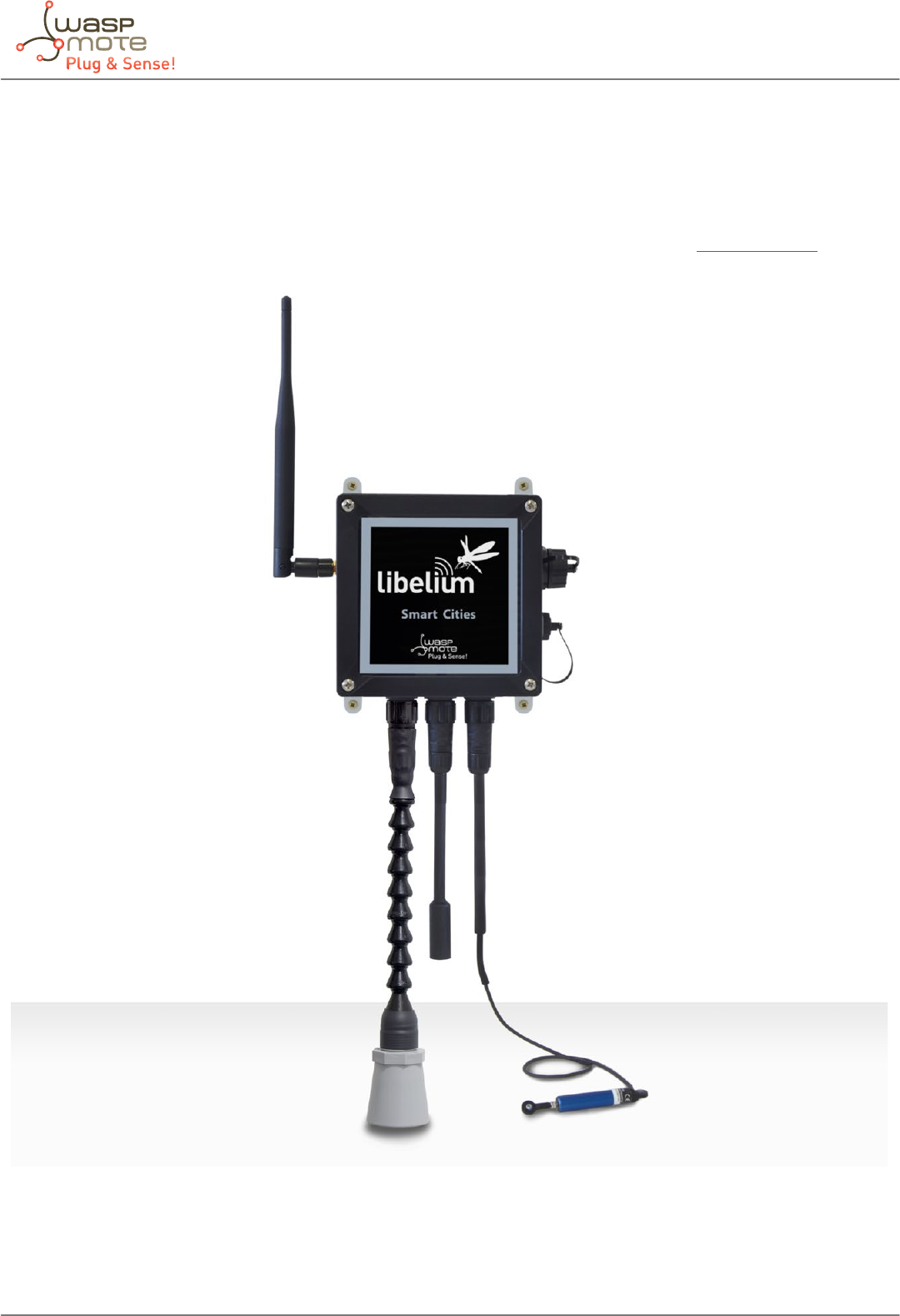
-75- v5.4
Waspmote Plug & Sense! - Sensors Guide
9. Smart Cities
9.1. General description
The main applications for this Waspmote Plug & Sense! model are noise maps (monitor in real time the acoustic levels in the
streets of a city), air quality, waste management, structural health, smart lighting, etc. Refer to Libelium website for more
information.
Figure: Smart Cities Waspmote Plug & Sense! Model
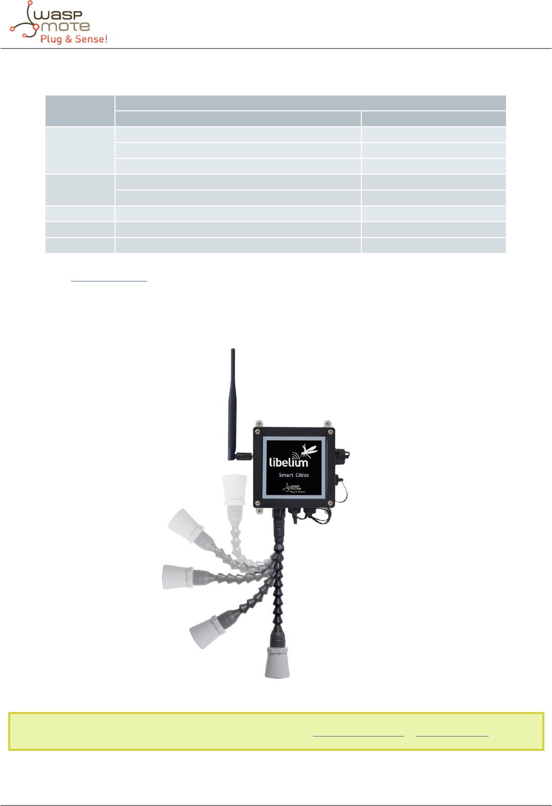
-76- v5.4
Waspmote Plug & Sense! - Sensors Guide
Sensor sockets are congured as shown in the gure below.
Sensor
Socket
Sensor probes allowed for each sensor socket
Parameter Reference
A
Temperature 9203
Soil temperature 86949*
Ultrasound (distance measurement) 9246
BHumidity 9204
Ultrasound (distance measurement) 9246
C Luminosity (LDR) 9205
D Noise sensor 9259
F Linear displacement 9319
* Ask Libelium Sales Department for more information.
Figure: Sensor sockets conguration for Smart Cities model
As we see in the gure below, thanks to the directionable probe, the ultrasound sensor probe may be placed in dierent
positions. The sensor can be focused directly to the point we want to measure.
Figure: Congurations of the ultrasound sensor probe
Note: For more technical information about each sensor probe go to the Development section in Libelium Website.
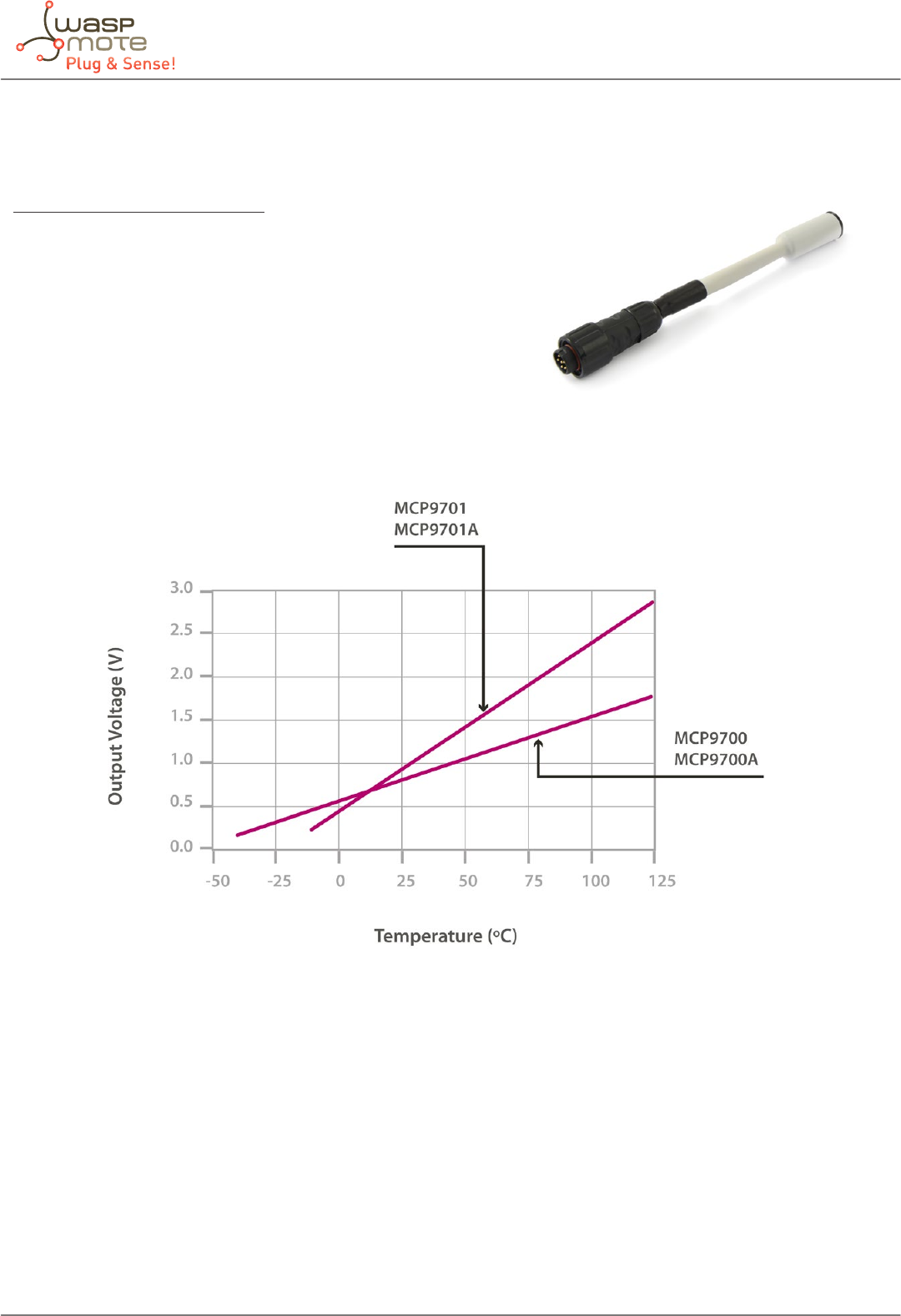
-77- v5.4
Waspmote Plug & Sense! - Sensors Guide
9.2. Temperature sensor probe
Sensor specications (MCP9700A)
Measurement range: [-40ºC ,+125ºC]
Output voltage: (0ºC): 500mV
Sensitivity: 10mV/ºC
Accuracy: ±2ºC (range 0ºC ~ +70ºC), ±4ºC (range -40 ~ +125ºC)
Supply voltage: 2.3 ~ 5.5V
Response time: 1.65 seconds (63% response from +30 to +125°C).
Typical consumption: 6μA
Maximum consumption: 12μA
Figure: Graph of the MCP9700A sensor output voltage with respect to temperature, taken from the Microchip sensor’s data sheet
The MCP9700A is an analog sensor which converts a temperature value into a proportional analog voltage. The range of output
voltages is between 100mV (-40°) and 1.75V (125°C), resulting in a variation of 10mV/°C, with 500mV of output for 0°C.
Figure: Image of the Temperature sensor probe (MCP9700A)
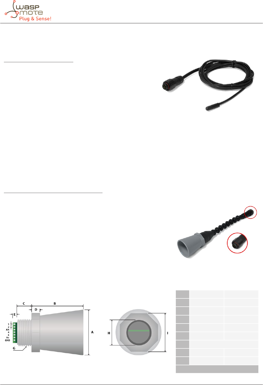
-78- v5.4
Waspmote Plug & Sense! - Sensors Guide
9.3. Soil Temperature sensor (DS18B20) probe
Sensor specications (DS18B20)
Measurement range: [-55ºC ,+125ºC]
Output voltage (0ºC): 500mV
Resolution: 12bits (0.0625ºC)
Accuracy: ±0.5ºC (range -10ºC ~ +85ºC)
Supply voltage: 3.0 ~ 5.5V
Response time: 1.65 seconds (63% response from +30 to +125°C)
Typical consumption: 1mA
Conversion time: 750ms
The DS18B20 is a temperature digital sensor which provides an accurate measurement and a high resolution (of up to 0.065ºC)
which communicates with the Waspmote’s microcontroller through the 1-Wire bus. It has been encapsulated in a plastic seal
that isolates it from humidity, thus allowing to use it in wet environments as long as for temperature measurement in soil or
liquids.
9.4. Ultrasound sensor probe
Sensor specications (XL-MaxSonar®-WRA1™)
Operation frequency: 42kHz
Maximum detection distance: 765cm
Maximum detection distance (analog output): 600cm (powered at 3.3V) - 700cm
(powered at 5V)
Sensitivity (analog output): 3.2mV/cm (powered at 3.3V) – 4.9mV/cm (powered
at 5V)
Power supply: 3.3 ~ 5V
Consumption (average): 2.1mA (powered at 3.3V) – 3.2mA (powered at 5V)
Consumption (peak): 50mA (powered at 3.3V) – 100mA (powered at 5V)
Usage: Indoors and outdoors (IP-67)
A1.72” dia. 43.8 mm dia.
B2.00” 50.7 mm
C0.58” 14.4 mm
D0.31” 7.9 mm
E0.18” 4.6 mm
F0.1” 2.54 mm
G3/4” National Pipe Thread Straight
H1.032” dia. 26.2 dia.
I1.37” 34.8 mm
weight: 1.76 oz. ; 50 grams
Figure: Ultrasonic XL-MaxSonar®-WRA1 sensor dimensions
Figure: Image of the Soil Temperature sensor probe (DS18B20)
Figure: Image of the Ultrasound sensor probe (XL-MaxSonar®-WRA1™)
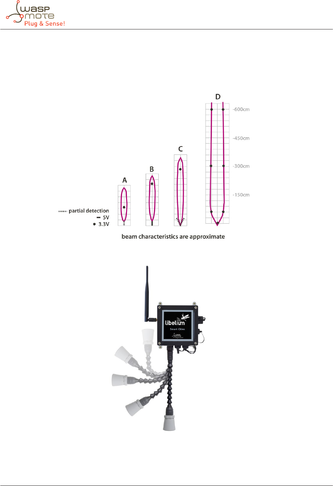
-79- v5.4
Waspmote Plug & Sense! - Sensors Guide
The MaxSonar® sensors from MaxBotix output an analog voltage proportional to the distance to the object detected. This sensor
can be powered at both 3.3V or 5V, although the detection range will be wider for the last one. The XL-MaxSonar®-WRA1™ sensor
is endowed with an IP-67 casing, so it can be used in outdoors applications, such as liquid level monitoring in storage tanks.
In the gure below we can see a diagram of the detection range of both sensors developed using dierent detection patterns
(a 0.63cm diameter dowel for diagram A, a 2.54cm diameter dowel for diagram B, a 8.25cm diameter rod for diagram C and a
28cm wide board for diagram D):
Figure: Diagram of the sensor beam extracted from the data sheet of the XL-MaxSonar®-WRA1™ sensor from MaxBotix
Figure: Image of congurations of the ultrasounds sensor probe
As we see in the gure, the ultrasound sensor probe may be placed in dierent positions. The sensor can be focused directly to
the point we want to measure.
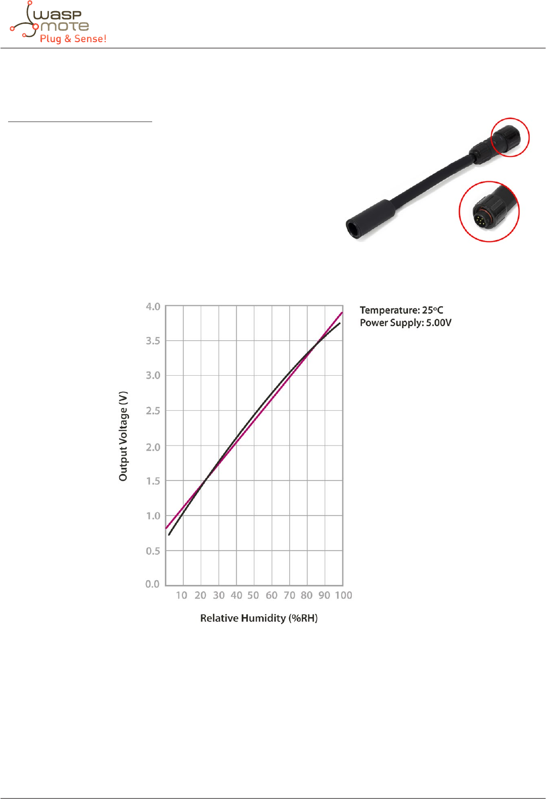
-80- v5.4
Waspmote Plug & Sense! - Sensors Guide
9.5. Humidity sensor probe
Sensor specications (808H5V5)
Measurement range: 0 ~ 100%RH
Output signal: 0.8 ~ 3.9V (25ºC)
Accuracy: <±4%RH (at 25ºC, range 30 ~ 80%), <±6%RH (range 0 ~ 100)
Supply voltage: 5VDC ±5%
Operating temperature: -40 ~ +85ºC
Response time: <15 seconds
Typical consumption: 0.38mA
Maximum consumption: 0.5mA
Figure: 808H5V5 humidity sensor output taken from the Sencera Co. Ltd sensor data sheet
This is an analog sensor which provides a voltage output proportional to the relative humidity in the atmosphere. As the
sensor’s signal range is outside of that permitted to the Waspmote’s input, a voltage divider has been installed which converts
the output voltage to values between 0.48 ~ 2.34V.
Figure: Image of the Humidity sensor probe (808H5V5)

-81- v5.4
Waspmote Plug & Sense! - Sensors Guide
9.6. Luminosity sensor probe
Sensor specications (LDR)
Resistance in darkness: 20MΩ
Resistance in light (10lux): 5 ~ 20kΩ
Spectral range: 400 ~ 700nm
Operating temperature: -30ºC ~ +75ºC
This is a resistive sensor whose conductivity varies depending on the intensity of light received on its photosensitive part.
The measurable spectral range (400nm – 700nm) coincides with the human visible spectrum so it can be used to detect light/
darkness in the same way that a human eye would detect it.
Figure: Image of the Luminosity sensor probe (LDR)
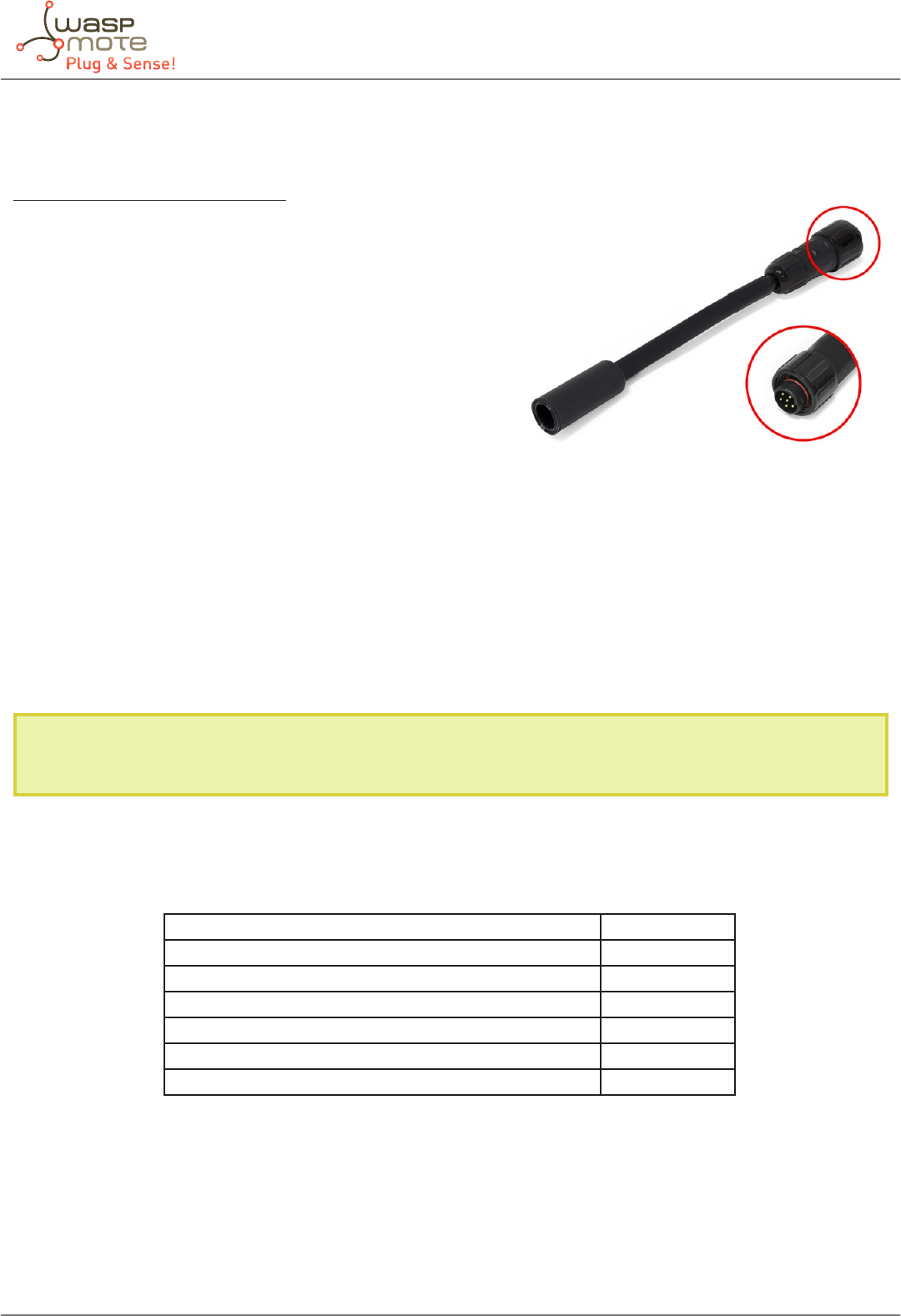
-82- v5.4
Waspmote Plug & Sense! - Sensors Guide
9.7. Noise sensor probe
Sensor specications (POM-2735P-R)
Sensitivity: -35±4dB
Impedance: <2.2kΩ
Directivity: Omnidirectional
Frequency: 20Hz~20kHz
Supply voltage: +3V (Standard), +10V (Maximum)
Maximum current consumption: 0.5mA
Sensitivity reduction: -3dB a 1.5V
Maximum sound pressure level: 114.5±10dBSPL approximately
S/N ratio: 60dB
Noise Level: 26 +/-1 dBA
Stage Measurement range: 50dBA~100dbA
The POM-2735P-R, introduced in the Smart Cities board to monitor the environmental noise, is an omnidirectional microphone
with an almost at response in the whole frequency range of human hearing, between 20Hz and 20kHz. A circuit to lter
the signal to adapt it to the A decibel scale and output a continuous voltage readable from the mote’s processor has been
introduced. When sold along with a microphone, the Smart Cities board is supplied calibrated by Libelium to return an output in
the range between 50dBA and 100dBA with an accuracy of ±2.5dBA. The calibration data associated to the microphone reading
is stored in the microcontroller’s EEPROM, between addresses 164 and 185. Be very careful not to overwrite this memory
positions or it could lead to an irreparable error when reading this sensor.
Note: Because of this needed calibration process, the user always must purchase any noise sensor probe with its corresponding
Plug & Sense! Smart Cities board.
The A weighting for the audio measurements is a compensation curve that is used to t the sound pressure measurement to the
ear response in function of the frequency, and is the most common standard for noise measurement. Below, we can see a table
of noise pressure generated by dierent sources in dBA.
Sound dBA
Audition threshold 0
Quiet Room 30
Normal conversation 60~70
Heavy trac (hearing loss under continued exposure) 90
Pain threshold 130
Jet engine (permanent damage) 140
Figure: Noise in dBA produced by dierent sources
Figure: Image of the Noise sensor probe (POM-2735P-R microphone)
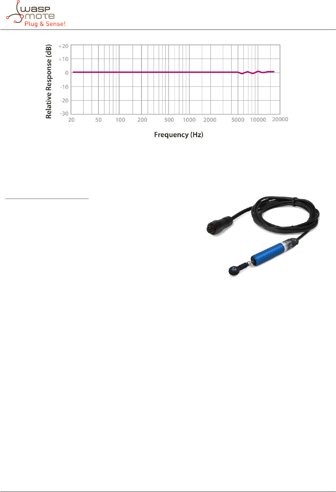
-83- v5.4
Waspmote Plug & Sense! - Sensors Guide
Figure: Graph of the frequency response of the POM-2735P-R extracted from the sensor’s data sheet
9.8. Linear Displacement sensor probe
Sensor specications (SLS095)
Electrical stroke: 10mm
Sensor resistance: 400Ω
Linearity: ±0.5%
Resolution: 10μm (imposed by the analog-to-digital conversion)
Supply Voltage: +8.9V
Power dissipation (20ºC): 0.2W
Temperature Operation: -30ºC ~ 100ªC
The SLS095 linear displacement sensor by Penny+Giles is a potentiometer whose wiper moves along with an axis guided by the
sensor’s body. Fixing both ends of the potentiometer at the sides of the crack we can measure its width by reading the voltage
at the wiper. For this, the sensor has been congured as a voltage divider, with one of the ends sourced from a 3V supply, the
other end grounded and the wiper connected to an input of the analog-to-digital converter of the Waspmote, which leads to
a resolution of 11μm approximately.
Figure: Image of the Linear Displacement sensor probe (SLS095)
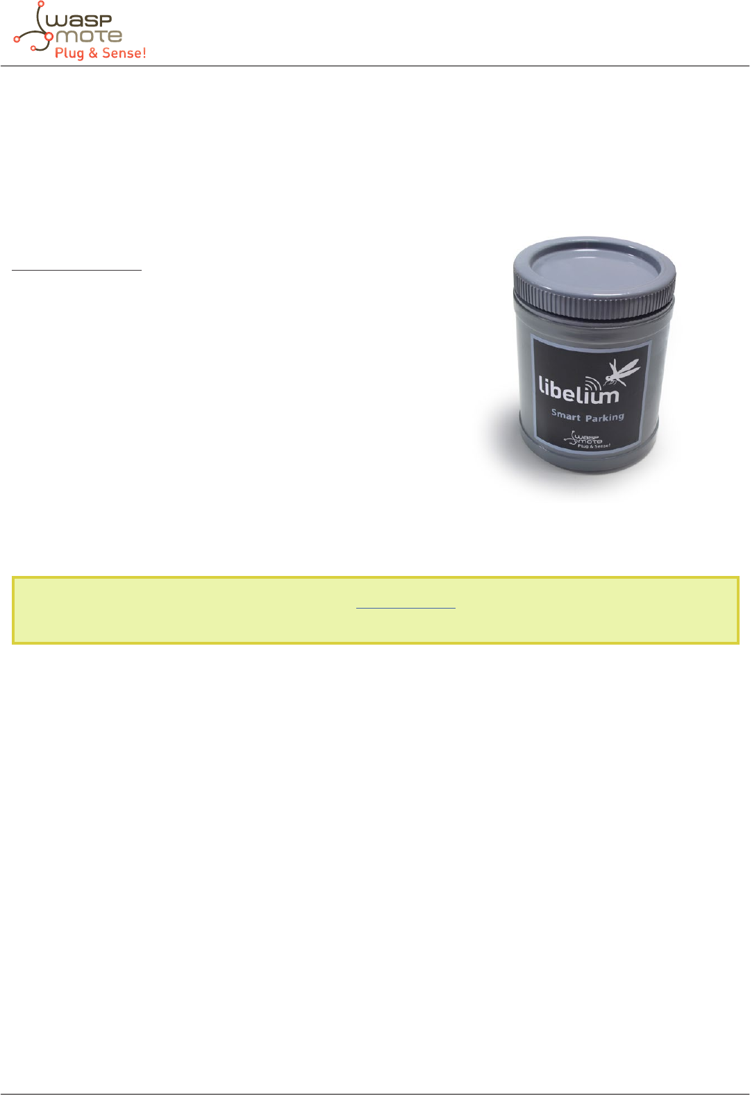
-84- v5.4
Waspmote Plug & Sense! - Sensors Guide
10. Smart Parking
10.1. General description
Smart Parking allows to detect available parking spots by placing the node under the pavement. It works with a magnetic
sensor which detects when a vehicle is present or not. Waspmote Plug & Sense! Can act as a repeater for a Smart parking node.
Sensor specications
Maximum Supply Voltage: 12V
Operation Temperature: -40 ~ 125ºC
Bridge Resistance: 600 ~ 1200Ω
Typical Output Voltage: 3,5mV/V/gauss
Average consumption: 15mA
Maximum consumption (peak): 500mA
Sensor sockets are no used for this model.
There are specic documents for parking applications at Libelium website. Refer to Smart Parking Technical guide to see
typical applications for this model and how to make a good installation.
Figure: Smart Parking enclosure
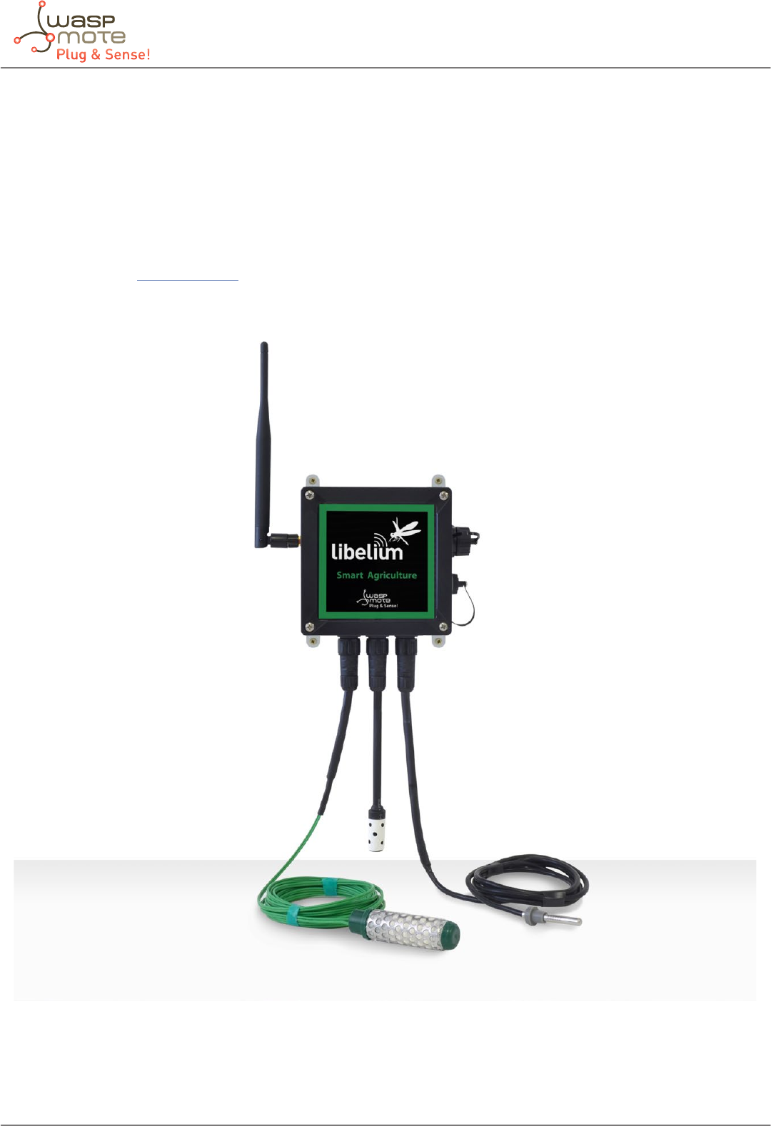
-85- v5.4
Waspmote Plug & Sense! - Sensors Guide
11. Smart Agriculture
11.1. General description
The Smart Agriculture models allow to monitor multiple environmental parameters involving a wide range of applications. It
has been provided with sensors for air and soil temperature and humidity (Sensirion), solar visible radiation, wind speed and
direction, rainfall, atmospheric pressure.
The main applications for this Waspmote Plug & Sense! model are precision agriculture, irrigation systems, greenhouses, weather
stations, etc. Refer to Libelium website for more information.
Two variants are possible for this model, normal and PRO. Next section describes each conguration in detail.
Figure: Smart Agriculture Waspmote Plug & Sense! Model

-86- v5.4
Waspmote Plug & Sense! - Sensors Guide
11.1.1. Normal
Sensor sockets are congured as shown in the gure below.
Sensor
Socket
Sensor probes allowed for each sensor socket
Parameter Reference
A Humidity + Temperature (Sensirion) 9247
B Atmospheric pressure 9250
CSoil temperature 86949*
Soil moisture 9248
DWeather Station WS-3000 (anemometer + wind vane +
pluviometer)
9256
E Soil moisture 9248
FLeaf wetness 9249
Soil moisture 9248
* Ask Libelium Sales Department for more information.
Figure: Sensor sockets conguration for Smart Agriculture model
Note: For more technical information about each sensor probe go to the Development section in Libelium Website.
11.1.2. PRO
Sensor sockets are congured as shown in the gure below.
Sensor
Socket
Sensor probes allowed for each sensor socket
Parameter Reference
A Humidity + Temperature (Sensirion) 9247
B Soil temperature 9255
C Solar radiation 9251, 9257
DSoil temperature 86949*
Soil moisture 9248
EDendrometers 9252, 9253, 9254
Soil moisture 9248
FLear wetness 9249
Soil moisture 9248
* Ask Libelium Sales Department for more information.
Figure: Sensor sockets conguration for Smart Agriculture PRO model
Note: For more technical information about each sensor probe go to the Development section in Libelium Website.
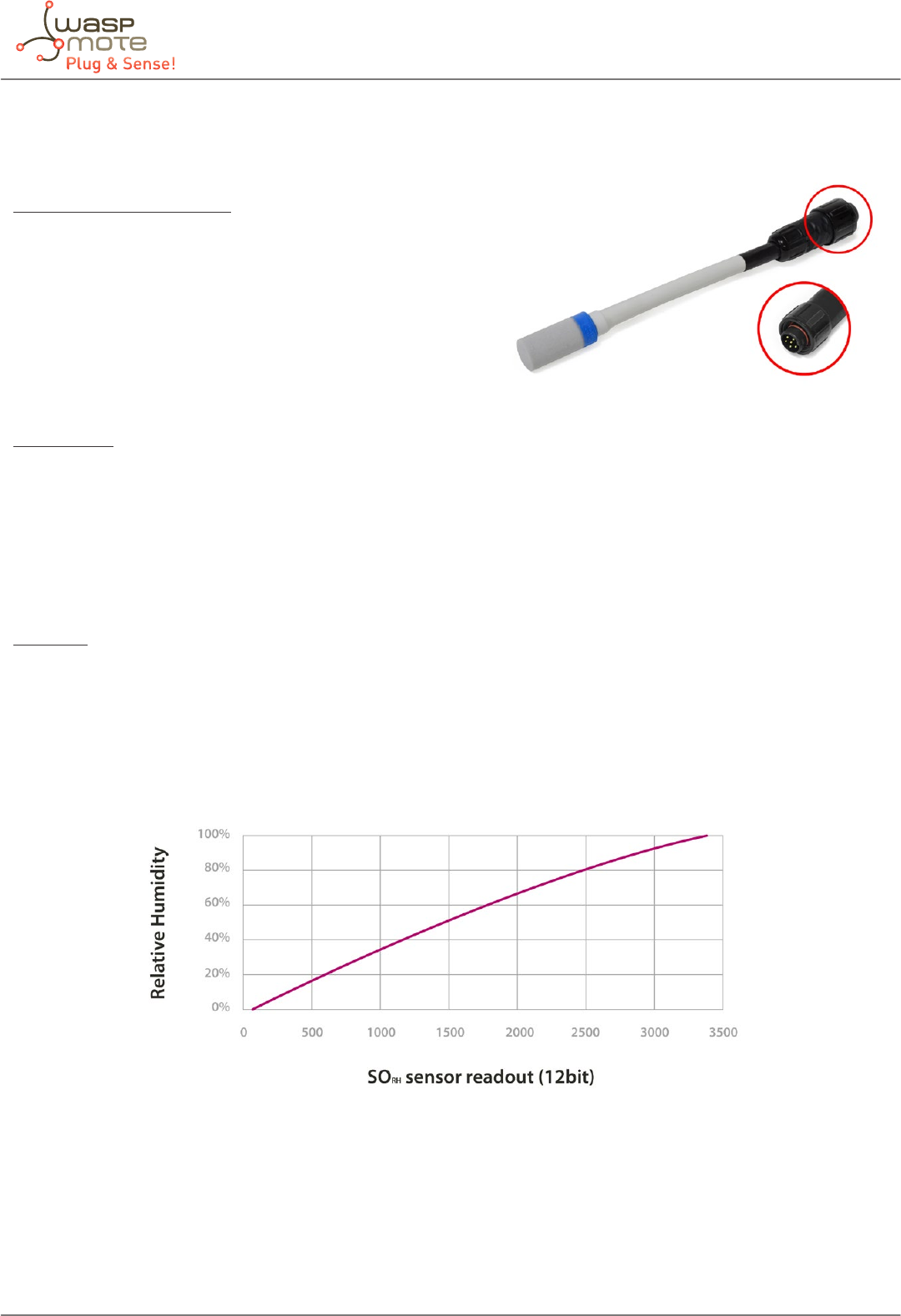
-87- v5.4
Waspmote Plug & Sense! - Sensors Guide
11.2. Temperature and Humidity sensor probe
Sensor specications (SHT75)
Power supply: 2.4 ~ 5.5V
Minimum consumption (sleep): 2µW
Consumption (measurement): 3mW
Average consumption: 90µW
Communication: Digital (two wire interface)
Storage temperature: 10 ~ 50ºC (0 ~ 80ºC maximum)
Storage humidity: 20 ~ 60%RH
Temperature:
Measurement range: -40ºC ~ +123.8ºC
Resolution: 0.04ºC (minimum), 0.01ºC (typical)
Accuracy: ±0.4ºC (range 0ºC ~ +70ºC), ±4ºC (range -40 ~ +125ºC)
Repeatability: ±0.1ºC
Response time (minimum): 5 seconds (63% of the response)
Response time (maximum): 30 seconds (63% of the response)
Humidity:
Measurement range: 0 ~ 100%RH
Resolution: 0.4%RH (minimum), 0.05%RH (typical)
Accuracy: ±1.8%RH
Repeatability: ±0.1%RH
Response time: 8 seconds
Figure: Graph of the sensor output with respect to relative humidity, taken from the Sensirion sensor’s data sheet
The SHT75 sensor by Sensirion incorporates a capacitive sensor for environmental relative humidity and a band gap sensor for
environmental temperature in the same package that permit to measure accurately both parameters. The sensor output is read
through two wires following a protocol similar to the I2C bus (Inter- Integrated Circuit Bus) implemented in the library of the
board, returning the temperature value in Celsius degree (ºC) and the humidity value in relative humidity percentage (%RH).
Figure: Image of the Temperature and Humidity sensor probe (SHT75)

-88- v5.4
Waspmote Plug & Sense! - Sensors Guide
11.3. Atmospheric Pressure sensor probe
Sensor specications (MPX4115A)
Measurement range: 15 ~ 115kPa
Output signal: 0,2 ~ 4,8V (0 ~ 85ºC)
Sensitivity: 46mV/kPa
Accuracy: <±1,5%V (0 ~ 85ºC)
Typical consumption: 7mA
Maximum consumption: 10mA
Supply voltage: 4.85 ~ 5.35V
Operation temperature: -40 ~ +125ºC
Storage temperature: -40 ~ +125ºC
Response time: 20ms
Figure: Graph of the MPX4115A sensor’s output voltage with regard to pressure taken from the Freescale sensor’s data sheet
The MPX4115A sensor converts atmospheric pressure to an analog voltage value in a range covering between 0.2V and 4.8V. As
this is a range which exceeds the maximum value admitted by Waspmote, its output has been adapted to t in a range between
0.12V and 2.88V.
Figure: Image of the Atmospheric Pressure sensor probe (MPX4115A)
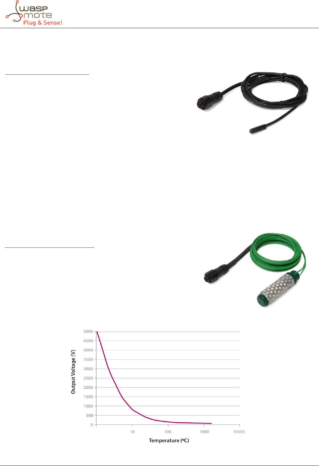
-89- v5.4
Waspmote Plug & Sense! - Sensors Guide
11.4. Soil Temperature sensor (DS18B20) probe
Sensor specications (DS18B20)
Measurement range: [-55ºC ,+125ºC]
Output voltage (0ºC): 500mV
Resolution: 12bits (0.0625ºC)
Accuracy: ±0.5ºC (range -10ºC ~ +85ºC)
Supply voltage: 3.0 ~ 5.5V
Response time: 1.65 seconds (63% response from +30 to +125°C)
Typical consumption: 1mA
Conversion time: 750ms
The DS18B20 is a temperature digital sensor which provides an accurate measurement and a high resolution (of up to 0.065ºC)
which communicates with the Waspmote’s microcontroller through the 1-Wire bus. It has been encapsulated in a plastic seal
that isolates it from humidity, thus allowing to use it in wet environments as long as for temperature measurement in soil or
liquids.
11.5. Soil moisture sensor probe
Sensor specications (Watermark)
Measurement range: 0 ~ 200cb
Frequency Range: 50 ~ 10000Hz approximately
Diameter: 22mm
Length: 76mm
Terminals: AWG 20
Figure: Output frequency of the Watermark sensor circuit with respect to the resistance of the sensor
Figure: Image of the Soil Temperature sensor probe (DS18B20)
Figure: Image of the Soil Moisture sensor probe (Watermark)
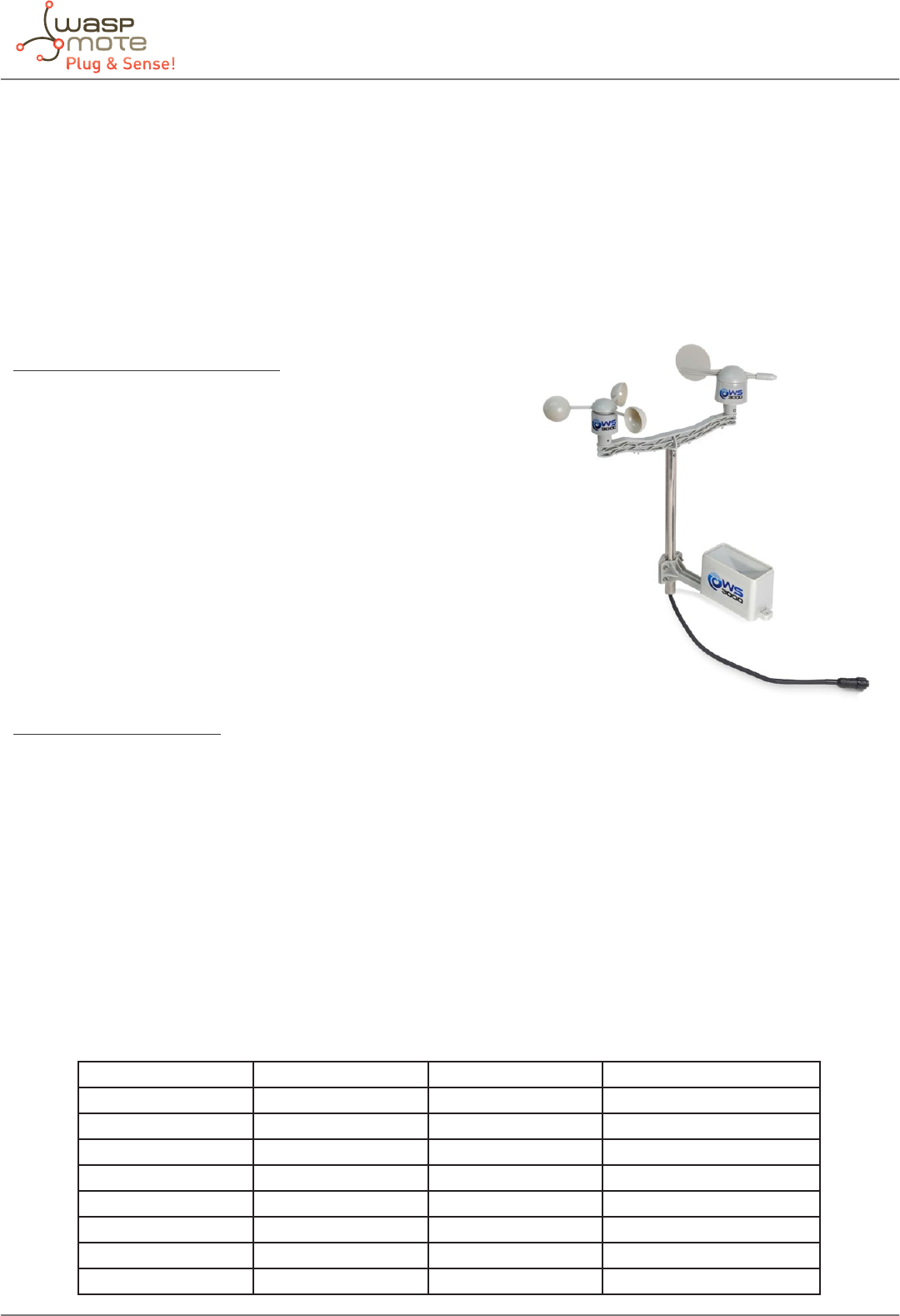
-90- v5.4
Waspmote Plug & Sense! - Sensors Guide
The Watermark sensor by Irrometer is a resistive type sensor consisting of two electrodes highly resistant to corrosion embedded
in a granular matrix below a gypsum wafer. The resistance value of the sensor is proportional to the soil water tension, a
parameter dependent on moisture that reects the pressure needed to extract the water from the ground. The function of the
library readValue returns the frequency output of the sensor’s adaptation circuit xin Herzs (Hz), for more information about
the conversion into soil water tension look at Appendix 1 of the Agriculture 2.0 Board technical guide.
11.6. Weather station WS-3000 probe
Sensor specications (Anemometer)
Sensitivity: 2.4km/h / turn
Wind Speed Range: 0 ~ 240km/h
Height: 7.1 cm
Arm length: 8.9 cm
Connector: RJ11
The anemometer chosen for Waspmote consists of a Reed switch
normally open that closes for a short period of time when the arms of
the anemometer complete a turn, so the output is a digital signal whose
frequency will be proportional to the wind speed in kilometers per hour
(km/h).
Sensor specications (Vane)
Height: 8.9 cm
Length: 17.8 cm
Maximum accuracy: 22.5º
Resistance range: 688Ω ~ 120kΩ
The wind vane consists of a basement that turns freely on a platform endowed with a net of eight resistances connected to
eight switches that are normally open and are closed (one or two) when a magnet in the basement acts on them, which permits
us to distinguish up to 16 dierent positions (the equivalent to a resolution of 22.5º). The equivalent resistance of the wind
vane, along with a 10kΩ resistance, form a voltage divider, powered at 3.3V, whose output can be measured in an analog input
of the microcontroller. The function of the library readValue also stores in variable vane_direction an 8 bits value which
corresponds with an identier of the pointing direction. Below, a table with the dierent values that the equivalent resistance
of the wind vane may take is shown, along with the direction corresponding to each value:
Direction (Degrees) Resistance (kΩ) Voltage (V) Identier
0 33 2.53 SENS_AGR_VANE_N
22.5 6.57 1.31 SENS_AGR_VANE_NNE
45 8.2 1.49 SENS_AGR_VANE_NE
67.5 0.891 0.27 SENS_AGR_VANE_ENE
90 1 0.3 SENS_AGR_VANE_E
112.5 0.688 0.21 SENS_AGR_VANE_ESE
135 2.2 0.59 SENS_AGR_VANE_SE
157.5 1.41 0.41 SENS_AGR_VANE_SSE
Figure: Image of the Weather Station WS-3000 probe

-91- v5.4
Waspmote Plug & Sense! - Sensors Guide
Direction (Degrees) Resistance (kΩ) Voltage (V) Identier
180 3.9 0.92 SENS_AGR_VANE_S
202.5 3.14 0.79 SENS_AGR_VANE_SSW
225 16 2.03 SENS_AGR_VANE_SW
247.5 14.12 1.93 SENS_AGR_VANE_WSW
270 120 3.05 SENS_AGR_VANE_W
292.5 42.12 2.67 SENS_AGR_VANE_WNW
315 64.9 2.86 SENS_AGR_VANE_NW
337.5 21.88 2.26 SENS_AGR_VANE_NNW
Besides, it is recommended to use the function getVaneFiltered in order to perform a mean ltered measurement during a
specied period of time. Thus, mechanical uctuations will be avoided and a more accurate measurement will be done.
Sensor specications (Pluviometer)
Height: 9.05 cm
Length: 23 cm
Bucket capacity: 0.28 mm of rain
The pluviometer consists of a small bucket that, once completely lled (0.28mm of water approximately), closes a switch,
emptying automatically afterwards. The result is a digital signal whose frequency is proportional to the intensity of rainfall
in millimeters of rain per minute (mm/min). The sensor is connected directly to a Waspmote digital input through a pull-up
resistance and to the interruption pin TXD1, allowing the triggering of an interruption of the microprocessor when the start of
the rain is detected.
Tip: the user can apply a little of paran on the pluviometer’s upper surface in order to help the rain drops to ow down to the
inside of the sensor.
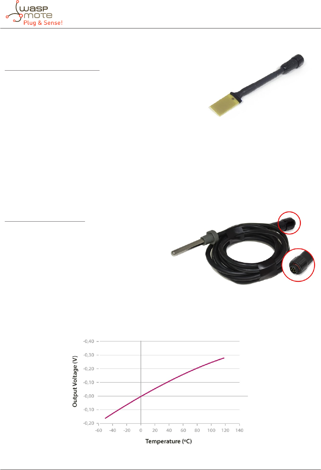
-92- v5.4
Waspmote Plug & Sense! - Sensors Guide
11.7. Leaf Wetness sensor probe
Sensor specications (Leaf Wetness)
Resistance Range: 5kΩ ~ >2MΩ
Output Voltage Range: 1V ~ 3.3V
Length: 3.95cm
Width: 1.95 cm
The leaf wetness sensor behaves as a resistance of a very high value (innite, for practical purposes) in absence of condensation
in the conductive combs that make it up, and that may fall down to about 5kΩ when it is completely submerged in water. The
voltage at its output is inversely proportional to the humidity condensed on the sensor, and can be read at an analog input of
Waspmote.
11.8. Soil Temperature sensor (PT1000) probe
Sensor specications (PT1000)
Measurement range: -50 ~ 300ºC
Accuracy: DIN EN 60751
Resistance (0ºC): 1000Ω
Diameter: 6mm
Length: 40mm
Cable: 2m
The resistance of the PT1000 sensor varies between approximately 920Ω and 1200Ω in the range considered useful in agriculture
applications (-20 ~ 50ºC approximately), which results in too low variations of voltage at signicant changes of temperature for
the resolution of the Waspmote’s analog-to-digital converter. The temperature value is returned in Celsius degree (ºC).
Figure: Output voltage of the PT1000 sensor with respect to temperature
Figure: Image of the Leaf Wetness sensor probe
Figure: Image of the Soil Temperature sensor sensor probe
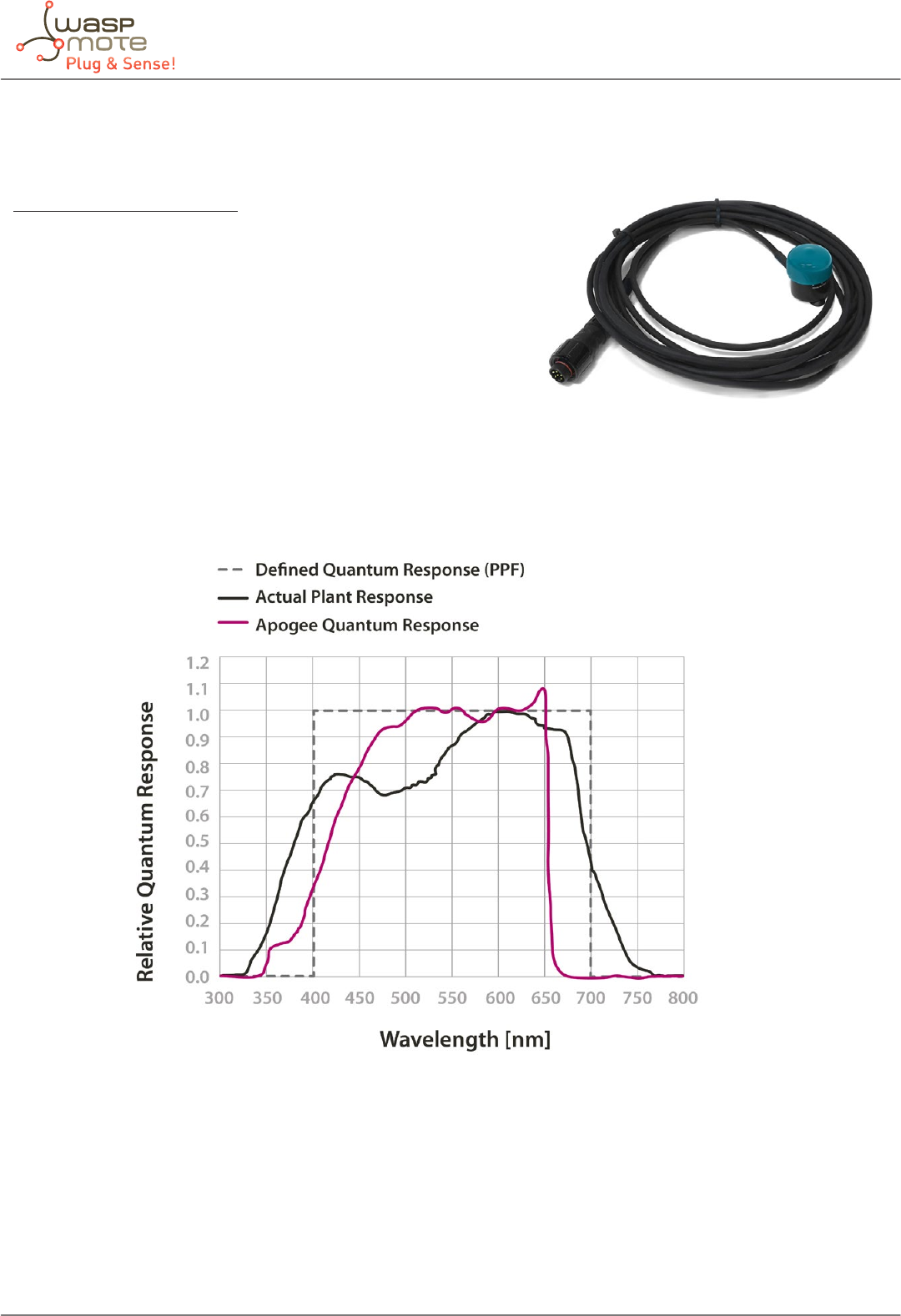
-93- v5.4
Waspmote Plug & Sense! - Sensors Guide
11.9. Solar Radiation sensor probe
Sensor specications (SQ-110)
Responsivity: 0.200mV / μmol·m-2s-1
Maximum radiation output: 400mV (2000μmol·m-2s-1)
Lineal range: 1000mV (5000μmol·m-2s-1)
Sensibility: 5.00μmol·m-2s-1/mV
Spectral range: 400 ~ 700nm
Accuracy: ±5%
Repeatability: ±1%
Diameter: 2.4cm
Height: 2.75cm
Cable length: 3m
Operation temperature: -40 ~ 55ºC
Operation humidity: 0 ~ 100%RH
Figure: Graph of the spectral response of the SQ-110 sensor compared to the photosynthetic response of a plant
The SQ-110 sensor, specically calibrated for the detection of solar radiation, provides at its output a voltage proportional to the
intensity of the light in the visible range of the spectrum, a key parameter in photosynthesis processes. It presents a maximum
output of 400mV under maximum radiation conditions and a sensitivity of 5.00μmol·m-2s-1/mV. In order to improve the accuracy
of the reading, this is carried out through a 16 bits analog-to-digital converter that communicates with the microprocessor of
the mote through the I2C.
Figure: Image of the Solar Radiation sensor probe
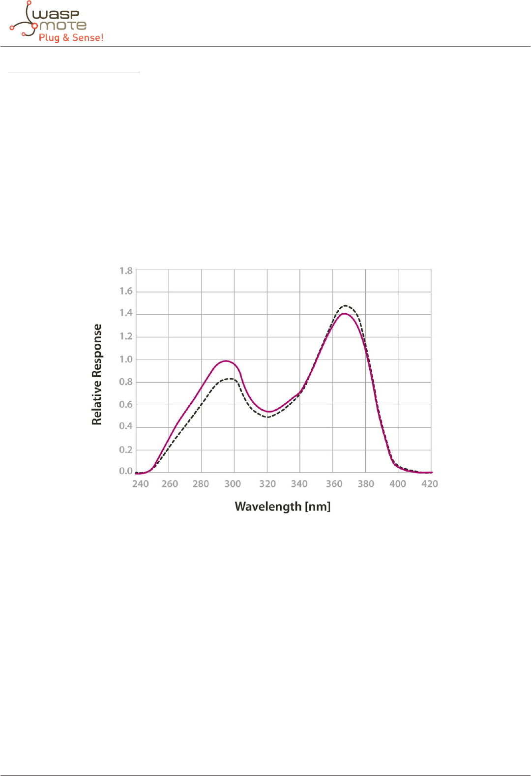
-94- v5.4
Waspmote Plug & Sense! - Sensors Guide
Sensor specications (SU-100)
Responsivity: 0.15mV / μmol·m-2s-1
Maximum radiation output: 26mV (170μmol·m-2s-1)
Lineal range: 60mV (400μmol·m-2s-1)
Sensibility: 6.5μmol·m-2s-1/mV
Spectral range: 250 ~ 400nm
Accuracy: ±10%
Repeatability: ±1%
Diameter: 2.4cm
Height: 2.75cm
Cable length: 3m
Operation humidity: 0 ~ 100%RH
Figure: Graph of the spectral response of the SU-100 sensor compared to the photosynthetic response of a plant
The SU-100 sensor, complementary to the SQ-110 sensor, provides at its output a voltage proportional to the intensity of the
light in the ultraviolet range of the spectrum. It presents a maximum output of 26mV under maximum radiation conditions and
a sensitivity of 6.5μmol·m-2s-1/mV. This sensor is read by the mote through the same 16 bits analog-to-digital converter used
with the SQ-110 sensor.
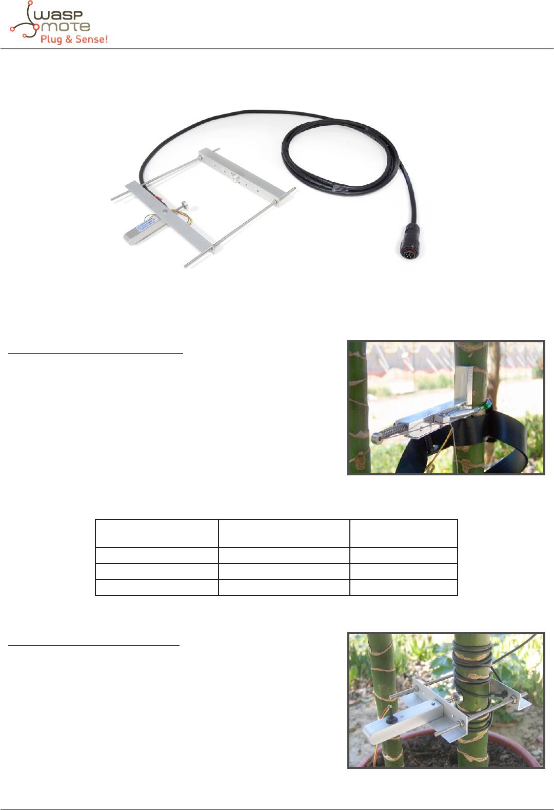
-95- v5.4
Waspmote Plug & Sense! - Sensors Guide
11.10. Dendrometer sensor probe
Figure: Image of the Dendrometer sensor probe
Sensor specications (Trunk diameter)
Trunk/branch diameter: From 2 cm
Accuracy: ±2μm
Temperature coecient: <0.1μm/K
Linearity: <2%
Operation temperature: -30 ~ 40ºC
Operation humidity: 0 ~ 100%RH
Cable length: 2m
Output range: 0 ~ 20kΩ
Range of the sensor: Function of the size of the tree:
Tree Diameter (cm) Measuring Range in
Circumference(mm)
Measuring Range in
Diameter (mm)
10 31.25 9.94
40 22.99 7.31
100 16.58 5.27
Sensor specications (Stem diameter)
Stem/branch diameter: 0 ~ 20cm
Range of the sensor: 11mm
Output range: 0 ~ 20kΩ
Accuracy: ±2μm
Temperature coecient: <0.1μm/K
Operation temperature: -30 ~ 40ºC
Operation humidity: 0 ~ 100%RH
Cable length: 2m
Figure: Ecomatik DC2 sensor
Figure: Ecomatik DD sensor

-96- v5.4
Waspmote Plug & Sense! - Sensors Guide
Sensor specications (Fruit diameter)
Fruit diameter: 0 ~ 11cm
Range of the sensor: 11mm
Output range: 0 ~ 20kΩ
Accuracy: ±2μm
Temperature coecient: <0.1μm/K
Operation temperature: -30 ~ 40ºC
Operation humidity: 0 ~ 100%RH
Cable length: 2m
The operation of the three Ecomatik dendrometers, DC2, DD and DF, is based on the variation of an internal resistance with
the pressure that the growing of the trunk, stem, branch or fruit exerts on the sensor. The circuit permits the reading of that
resistance in a full bridge conguration through a 16 bits analog-to-digital converter whose reference is provided by a high
precision 3V voltage reference in order to acquire the most accurate and stable measurements possible, returning its value in
mm.
Figure: Ecomatik DF sensor
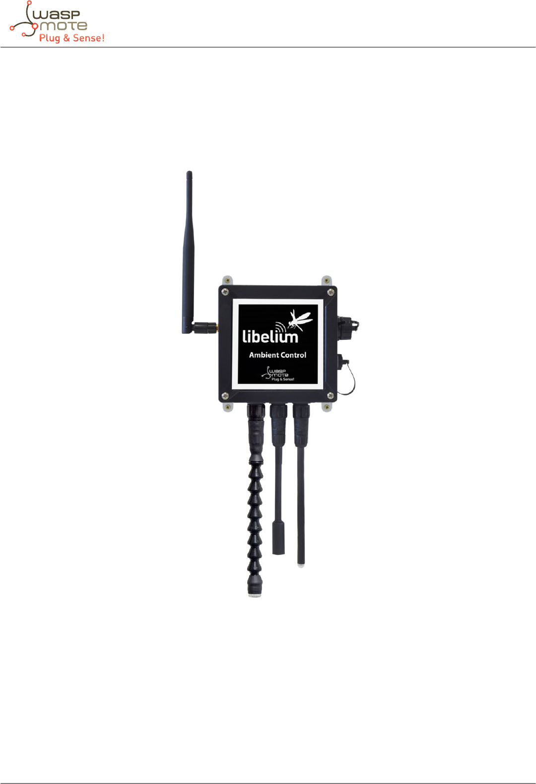
-97- v5.4
Waspmote Plug & Sense! - Sensors Guide
12. Ambient Control
12.1. General description
This model is designed to monitor main environment parameters in an easy way. Only three sensor probes are allowed for this
model, as shown in next table.
Figure: Ambient Control Waspmote Plug & Sense! model
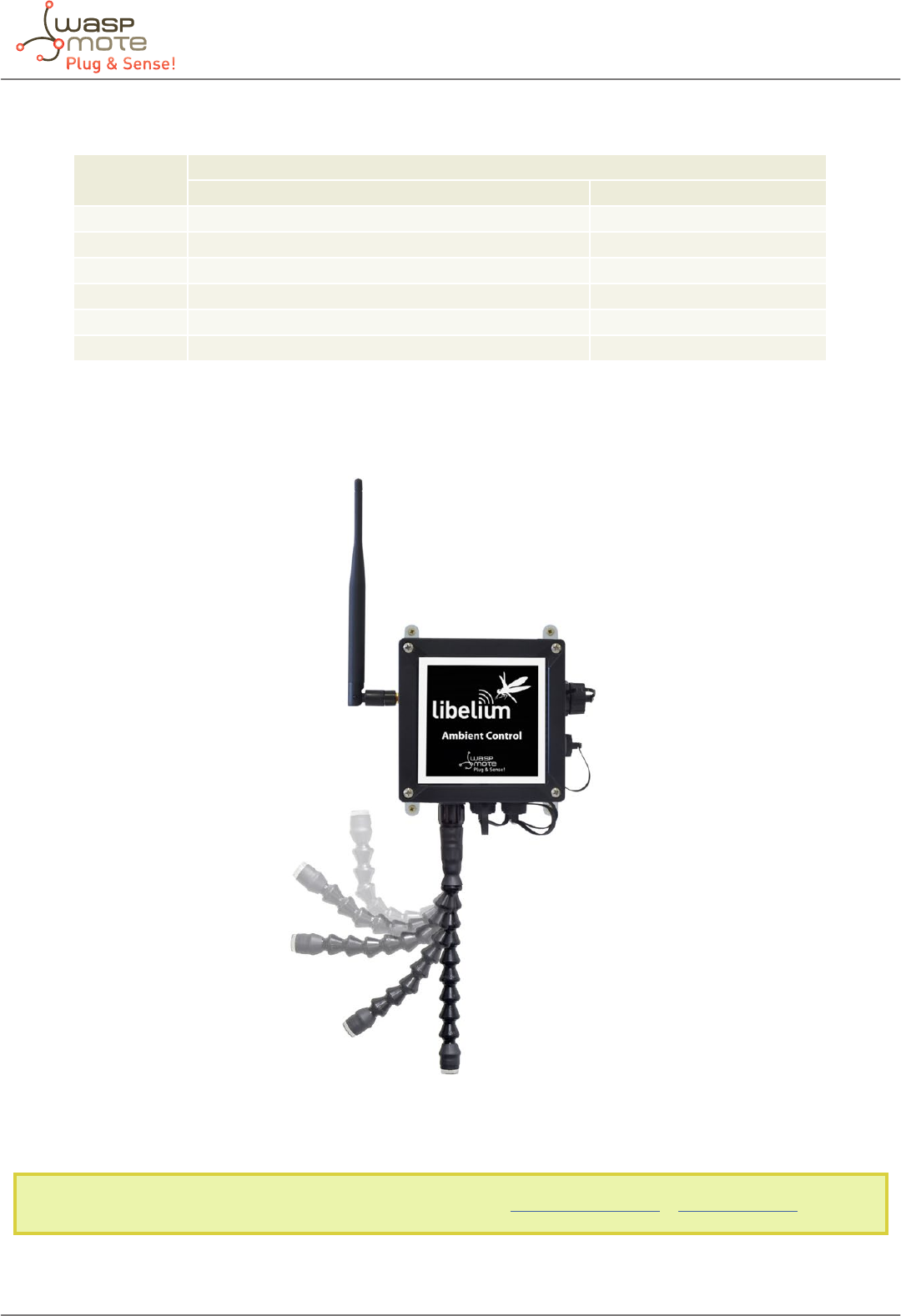
-98- v5.4
Waspmote Plug & Sense! - Sensors Guide
Sensor sockets are congured as it is shown in gure below.
Sensor
Socket
Sensor probes allowed for each sensor socket
Parameter Reference
A Humidity + Temperature (Sensirion) 9247
B Luminosity (LDR) 9205
C Luminosity (Luxes accuracy) 9325
D Not used -
E Not used -
F Not used -
Figure: Sensor sockets conguration for Ambient Control model
As we see in the gure below, thanks to the directionable probe, the luminosity sensor probe may be placed in dierent
positions. The sensor can be focused directly to the light source we want to measure.
Figure: Congurations of the Luminosity sensor probe (luxes accuracy)
Note: For more technical information about each sensor probe go to the Development section in Libelium Website.

-99- v5.4
Waspmote Plug & Sense! - Sensors Guide
12.2. Temperature and Humidity sensor probe
Sensor specications (SHT75)
Power supply: 2.4 ~ 5.5V
Minimum consumption (sleep): 2µW
Consumption (measurement): 3mW
Average consumption: 90µW
Communication: Digital (two wire interface)
Storage temperature: 10 ~ 50ºC (0 ~ 80ºC maximum)
Storage humidity: 20 ~ 60%RH
Temperature:
Measurement range: -40ºC ~ +123.8ºC
Resolution: 0.04ºC (minimum), 0.01ºC (typical)
Accuracy: ±0.4ºC (range 0ºC ~ +70ºC), ±4ºC (range -40 ~ +125ºC)
Repeatability: ±0.1ºC
Response time (minimum): 5 seconds (63% of the response)
Response time (maximum): 30 seconds (63% of the response)
Humidity:
Measurement range: 0 ~ 100%RH
Resolution: 0.4%RH (minimum), 0.05%RH (typical)
Accuracy: ±1.8%RH
Repeatability: ±0.1%RH
Response time: 8 seconds
Figure: Graph of the sensor output with respect to relative humidity, taken from the Sensirion sensor’s data sheet
The SHT75 sensor by Sensirion incorporates a capacitive sensor for environmental relative humidity and a band gap sensor for
environmental temperature in the same package that permit to measure accurately both parameters. The sensor output is read
through two wires following a protocol similar to the I2C bus (Inter- Integrated Circuit Bus) implemented in the library of the
board, returning the temperature value in Celsius degree (ºC) and the humidity value in relative humidity percentage (%RH).
Figure: Image of the Temperature and Humidity sensor probe (SHT75)

-100- v5.4
Waspmote Plug & Sense! - Sensors Guide
12.3. Luminosity sensor probe (LDR)
Sensor specications (LDR)
Resistance in darkness: 20MΩ
Resistance in light (10lux): 5 ~ 20kΩ
Spectral range: 400 ~ 700nm
Operating temperature: -30ºC ~ +75ºC
This is a resistive sensor whose conductivity varies depending on the intensity of light received on its photosensitive part.
The measurable spectral range (400nm – 700nm) coincides with the human visible spectrum so it can be used to detect light/
darkness in the same way that a human eye would detect it.
Note: The Luminosity sensor probe used in Ambient Control is dierent from the probe used in the other Plug & Sense! Applications,
so they are not interchangeable.
Figure: Image of the Luminosity sensor probe (LDR)
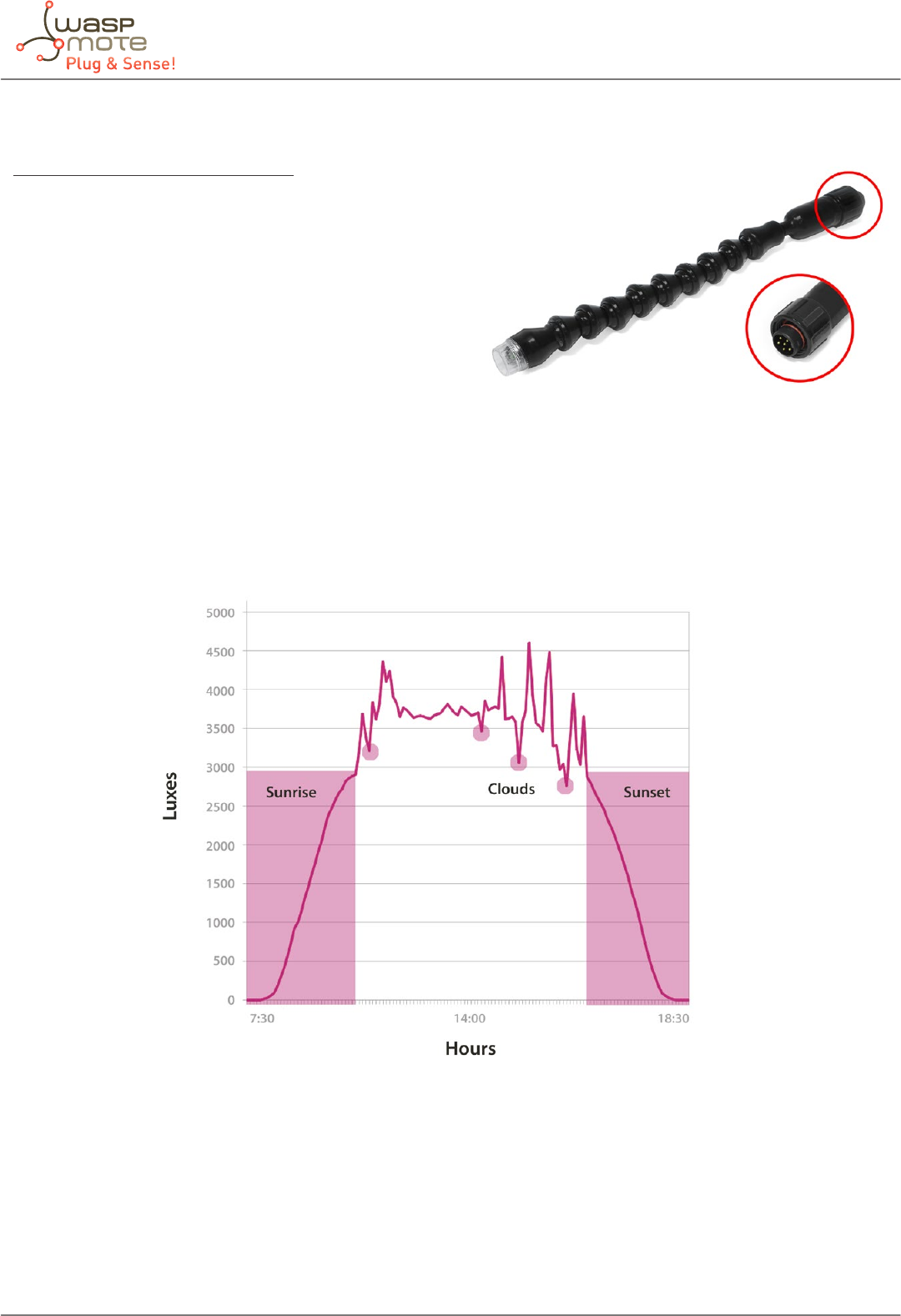
-101- v5.4
Waspmote Plug & Sense! - Sensors Guide
12.4. Luminosity sensor probe (Luxes accuracy)
Sensor specications (Luxes accuracy)
Dynamic range: 0.1 to 40000 Lux
Spectral range: 300 – 1100 nm
Voltage range: 2.7 – 3.6V
Operating temperature: -30ºC to +80ºC
Typical consumption: 0.24mA
Maximum consumption: 0.6mA
Usage: Indoors and outdoors
This is a light-to-digital converter that transforms light intensity into a digital signal output. This device combines one broadband
photo-diode (visible plus infrared) and one infrared-responding photo-diode on a single CMOS integrated circuit capable of
providing a near-photopic response over an eective 20-bit dynamic range (16-bit resolution). Two integrating ADCs convert
the photo-diode currents to a digital output that represents the irradiance measured on each channel. This digital output in lux
is derived using an empirical formula to approximate the human eye response.
Figure: Image of the Luminosity sensor probe (Luxes accuracy)
Figure: Image of the Luminosity sensor probe (Luxes accuracy)
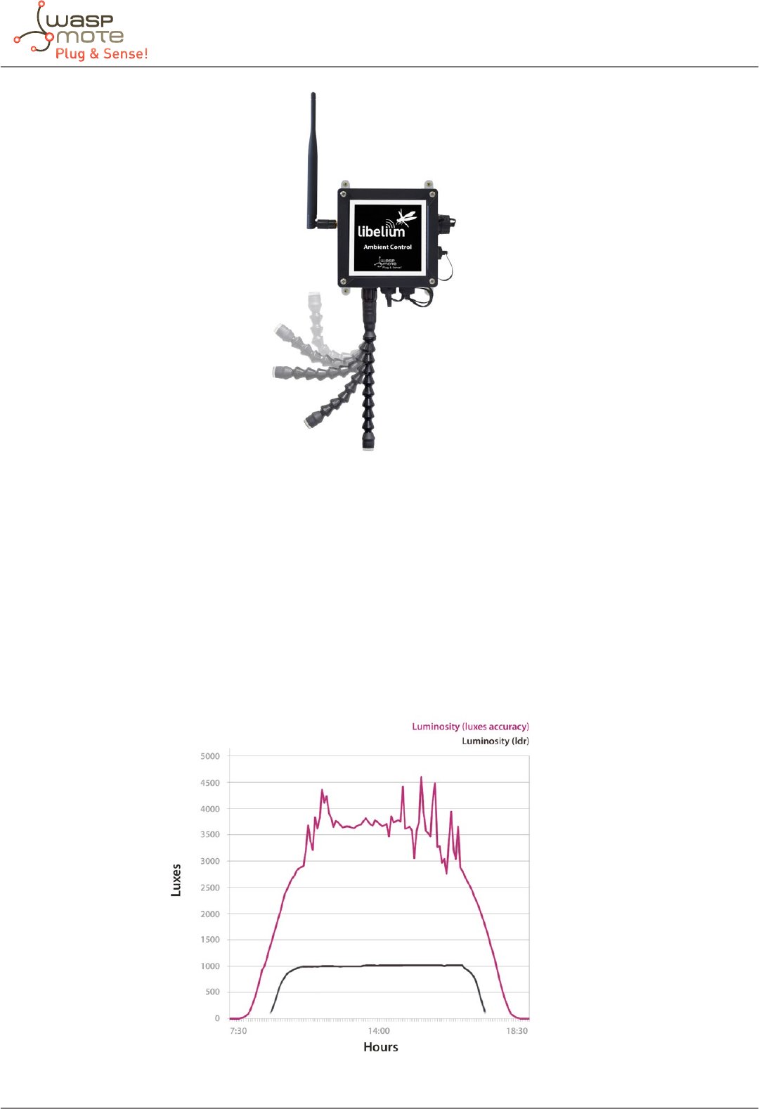
-102- v5.4
Waspmote Plug & Sense! - Sensors Guide
Figure: Image of congurations of the Luminosity sensor probe (Luxes accuracy)
As we see in the gure, the luminosity sensor probe may be placed in dierent positions. The sensor can be focused directly to
the light source we want to measure.
If you want to focused it directly to the light source, be sure that it (the sun, a spotlight...) emits less light than the maximum
value allowed by the sensor. If we try to measure a higher value the sensor will saturate.
12.5. Comparative between Light and Luminosity sensor
As it is shown in the graph below, the Luminosity sensor probe (LDR) can measure the presence of a light source below or above
a certain threshold. Dierent from the Luminosity sensor probe (Luxes accuracy) that can measure the exact quantity of the
light in luxes. It allows us to appreciate dierent values along the time.
Figure: Comparison of the responses of the Luminosity sensor probe (Luxes accuracy) and the Luminosity sensor probe (LDR)
-103- v5.4
Waspmote Plug & Sense! - Sensors Guide
13. Radiation Control
13.1. General description
The main application for this Waspmote Plug & Sense! conguration is to measure radiation levels using a Geiger sensor. For
this model, the Geiger tube is already included inside Waspmote, so the user does not have to connect any sensor probe to the
enclosure. The rest of the other sensor sockets are not used.
Figure: Radiation Control Waspmote Plug & Sense! model
Sensor sockets are no used for this model.
Sensor specications (Geiger tube)
Manufacturer: North Optic
Radiation Detection: Beta, Gamma [β, γ]
Length: 111mm
Diameter: 11mm
Recommended Voltage: 350V
Plateau Voltage: 360-440V
Sensitivy γ (60Co): 65cps/(µR/s)
Sensitivy γ (equivalent Sievert): 108cpm / (µSv/h)
Max cpm: 30000
cps/mR/h: 18
cpm/m/h: 1080
cpm/µSv/h: 123.147092360319
Factor: 0.00812037037037
Note: For more technical information about each sensor probe go to the Development section in Libelium Website.

-104- v5.4
Waspmote Plug & Sense! - Sensors Guide
14. Documentation Changelog
From 5.3 to 5.4:
• New section for the new sensor probes format
From 5.2 to 5.3:
• The Smart Metering line was discontinued
• The Hall eect sensor probe changed
From 5.1 to 5.2:
• Socket A was deleted from the Smart Water Plug & Sense! Because it is no longer needed.
From 5.0 to 5.1:
• References to the new Smart Water Ions line
• Dissolved ions sensors were moved from Smart Water to Smart Water Ions
• Updated specications for the Gases PRO sensors Carbon Monoxide (CO), Molecular Oxygen (O2), Molecular Hydrogen (H2)
and Hydrogen Sulde (H2S)
From 4.9 to 5.0:
• Added chapter for the new Smart Environment PRO / Gases PRO line
• The Dust sensor is discontinued in the Plug & Sense! ecosystem; now, the recommended option is the Particle Matter sensor
From 4.8 to 4.9:
• Removed the discontinued water ow sensors (FS100A, FS200A and FS400) and added the new equivalent ones (YF-S401,
FS300A and YF-G1)
From 4.7 to 4.8:
• Added references to the new Turbidity sensor for Smart Water
• Added MiCS-2714 NO2 sensor, MiCS-2614 O3 sensor and MiCS-5524 VOC’s sensor (new versions)
• The correct noise sensor’s output is indicated: dBA
• Introduced the new equivalent noise sensor’s name
• Noted that the dust sensor probe must be maintained periodically, and purchased with the big Solar Shield
• Noted that the noise sensor probe and Plug & Sense! Smart Cities must be purchased together
From 4.6 to 4.7:
• Updated list of calibrated gas sensors
From 4.5 to 4.6:
• Added chapter for the new Smart Water line
From 4.4 to 4.5:
• Added references to the new Calibrated Gas Sensor line
From 4.3 to 4.4:
• Changed Weather Meters name to Weather Station WS-3000
• Details about new ltered function for reading the wind vane
From 4.2 to 4.3:
• Added new Liquid Presence sensor.

-105- v5.4
Waspmote Plug & Sense! - Sensors Guide
From 4.1 to 4.2:
• Errata correction in Air Pollutants sensors and one gure.
• Creation of the “Documentation Changelog” chapter.
