Waspmote Technical Guide
User Manual:
Open the PDF directly: View PDF ![]() .
.
Page Count: 147 [warning: Documents this large are best viewed by clicking the View PDF Link!]
- 1. Introduction
- 2. Waspmote Kit
- 2.1. General and safety information
- 2.2. Conditions of use
- 2.3. Assembly
- 3.2. General view
- 3.3. Sensor probes
- 3.4. Solar powered
- 3.5. External Battery Module
- 3.6. Programming the Nodes
- 3.7. Program in minutes
- 3.8. Radio interfaces
- 3.9. Industrial Protocols
- 3.10. GPS
- 3.11. Models
- 3.11.1. Smart Environment PRO
- 3.11.2. Smart Security
- 3.11.3. Smart Water
- 3.11.4. Smart Water Xtreme
- 3.11.5. Smart Water Ions
- 3.11.6. Smart Parking
- 3.11.7. Smart Agriculture
- 3.11.8. Smart Agriculture Xtreme
- 3.11.9. Ambient Control
- 3.11.10. Smart Cities PRO
- 3.11.11. Radiation Control
- 3.11.12. 4-20 mA Current Loop
- 4. Hardware
- 5. Architecture and system
- 6. Interruptions
- 7. Energy system
- 8. Sensors
- 9. 802.15.4/ZigBee/RF modules
- 10. LoRaWAN modules
- 11. LoRa module
- 12. Sigfox modules
- 13. WiFi PRO module
- 14. Bluetooth Pro module
- 15. Bluetooth Low Energy module
- 16. GPRS module
- 17. 3G module
- 18. 4G module
- 19. NB-IoT / Cat-M module
- 20. RFID/NFC module
- 21. Industrial Protocols
- 22. Expansion Radio Board
- 23. Over the Air Programming (OTA)
- 24. Encryption libraries
- 25. GPS
- 26. SD memory card
- 27. Energy Consumption
- 28. Power supplies
- 29. Working environment
- 30. Interacting with Waspmote
- 31. Meshlium - The IoT Gateway
- 32. Certifications
- 33. Maintenance
- 34. Disposal and recycling
- 35. Documentation changelog
Waspmote
Technical Guide

-2- v8.2
Document version: v8.2 - 02/2019
© Libelium Comunicaciones Distribuidas S.L.
Index
INDEX
1. Introduction ..........................................................................................................................6
2. Waspmote Kit ........................................................................................................................7
2.1. General and safety information ...................................................................................................... 7
2.2. Conditions of use .............................................................................................................................. 8
2.3. Assembly .......................................................................................................................................... 10
3.2. General view .................................................................................................................................... 16
3.2.1. Specications .......................................................................................................................16
3.2.2. Parts included ......................................................................................................................19
3.2.3. Identication ........................................................................................................................20
3.3. Sensor probes ................................................................................................................................. 22
3.4. Solar powered ................................................................................................................................. 23
3.5. External Battery Module ................................................................................................................ 24
3.6. Programming the Nodes ................................................................................................................ 25
3.7. Program in minutes ........................................................................................................................ 26
3.8. Radio interfaces............................................................................................................................... 27
3.9. Industrial Protocols ......................................................................................................................... 28
3.10. GPS ................................................................................................................................................. 30
3.11. Models ............................................................................................................................................ 31
3.11.1. Smart Environment PRO ..................................................................................................32
3.11.2. Smart Security ...................................................................................................................34
3.11.3. Smart Water .......................................................................................................................36
3.11.4. Smart Water Xtreme .........................................................................................................38
3.11.5. Smart Water Ions ..............................................................................................................40
3.11.6. Smart Parking ....................................................................................................................43
3.11.7. Smart Agriculture ..............................................................................................................44
3.11.8. Smart Agriculture Xtreme ................................................................................................47
3.11.9. Ambient Control ................................................................................................................50
3.11.10. Smart Cities PRO .............................................................................................................52
3.11.11. Radiation Control ............................................................................................................54
3.11.12. 4-20 mA Current Loop ....................................................................................................55
4. Hardware .............................................................................................................................56
4.1. Modular architecture ...................................................................................................................... 56
4.2. Specications ................................................................................................................................... 56
4.3. Block diagram .................................................................................................................................. 57
4.4. Electrical data .................................................................................................................................. 58
4.5. I/O .................................................................................................................................................... 59
4.5.1. Analog pins ...........................................................................................................................60

-3- v8.2
Index
4.5.2. Digital pins ............................................................................................................................60
4.5.3. PWM ......................................................................................................................................60
4.5.4. UART .....................................................................................................................................61
4.5.5. I2C .........................................................................................................................................61
4.5.6. SPI ..........................................................................................................................................61
4.5.7. USB ........................................................................................................................................61
4.6. Real Time Clock - RTC ..................................................................................................................... 61
4.7. LEDs .................................................................................................................................................. 63
5. Architecture and system ....................................................................................................64
5.1. Concepts .......................................................................................................................................... 64
5.2. Timers ............................................................................................................................................... 65
5.2.1. Watchdog .............................................................................................................................65
5.2.2. RTC Watchdog for reseting Waspmote .............................................................................65
5.2.3. RTC ........................................................................................................................................66
6. Interruptions .......................................................................................................................67
7. Energy system .....................................................................................................................68
7.1. Concepts .......................................................................................................................................... 68
7.2. Sleep mode ...................................................................................................................................... 69
7.3. Deep Sleep mode ............................................................................................................................ 70
7.4. Hibernate mode .............................................................................................................................. 70
8. Sensors .................................................................................................................................72
8.1. Accelerometer ................................................................................................................................. 72
8.2. Integration of new sensors ............................................................................................................ 75
8.3. Sensor Boards ................................................................................................................................. 76
8.4. Power ................................................................................................................................................ 82
9. 802.15.4/ZigBee/RF modules .............................................................................................. 83
9.1. XBee-PRO 802.15.4 ......................................................................................................................... 84
9.2. XBee-PRO ZigBee ............................................................................................................................ 86
9.3. XBee 868LP ...................................................................................................................................... 87
9.4. XBee-PRO 900HP ............................................................................................................................. 89
9.5. XBee-PRO DigiMesh ........................................................................................................................ 90
10. LoRaWAN modules ...........................................................................................................91
11. LoRa module ......................................................................................................................93

-4- v8.2
12. Sigfox modules ..................................................................................................................94
13. WiFi PRO module ...............................................................................................................96
14. Bluetooth Pro module ......................................................................................................97
15. Bluetooth Low Energy module ........................................................................................99
16. GPRS module ...................................................................................................................101
17. 3G module ........................................................................................................................ 102
18. 4G module ........................................................................................................................ 103
19. NB-IoT / Cat-M module ...................................................................................................105
20. RFID/NFC module ............................................................................................................ 108
21. Industrial Protocols ........................................................................................................110
21.1. Introduction ................................................................................................................................ 110
21.2. RS-485/Modbus module ............................................................................................................ 112
21.3. CAN Bus module ......................................................................................................................... 113
21.4. Modbus ........................................................................................................................................ 114
22. Expansion Radio Board...................................................................................................115
23. Over the Air Programming (OTA) ..................................................................................116
23.1. Overview ...................................................................................................................................... 116
23.2. OTA with 4G/GPRS/WiFi modules via FTP ................................................................................ 116
24. Encryption libraries ........................................................................................................118
25. GPS .................................................................................................................................... 119
26. SD memory card ..............................................................................................................121
27. Energy Consumption ......................................................................................................122
27.1. Consumption tables ................................................................................................................... 122
28. Power supplies ................................................................................................................124
28.1. Battery .......................................................................................................................................... 124
28.2. Solar panel ................................................................................................................................... 126
28.3. USB ............................................................................................................................................... 128
29. Working environment ....................................................................................................130
Index

-5- v8.2
30. Interacting with Waspmote ...........................................................................................131
30.1. Receiving XBee frames with Waspmote Gateway ................................................................... 131
30.1.1. Waspmote Gateway ....................................................................................................... 131
30.1.2. Linux receiver ................................................................................................................. 132
30.1.3. Windows receiver ........................................................................................................... 136
30.1.4. Mac-OS receiver ............................................................................................................. 138
31. Meshlium - The IoT Gateway .........................................................................................139
31.1. Meshlium Storage Options ........................................................................................................ 139
31.2. Meshlium connection options ................................................................................................... 140
31.3. Meshlium Visualizer .................................................................................................................... 141
31.4. Cloud Connectors ....................................................................................................................... 142
32. Certications ................................................................................................................... 143
33. Maintenance ....................................................................................................................144
34. Disposal and recycling ....................................................................................................145
35. Documentation changelog ............................................................................................146
Index

-6- v8.2
Introduction
1. Introduction
This guide explains the features related to our product line Waspmote v15, released on October 2016.
If you are using previous versions of our products, please use the corresponding guides, available on our
Development website.
You can get more information about the generation change on the document “New generation of Libelium product
lines”.

-7- v8.2
Waspmote Kit
2. Waspmote Kit
Important:
•All documents and any examples they contain are provided as-is and are subject to change without notice.
Except to the extent prohibited by law, Libelium makes no express or implied representation or warranty of
any kind with regard to the documents, and specically disclaims the implied warranties and conditions of
merchantability and tness for a particular purpose.
•The information on Libelium’s websites has been included in good faith for general informational purposes
only. It should not be relied upon for any specic purpose and no representation or warranty is given as to
its accuracy or completeness.
2.1. General and safety information
•In this section, the term “Waspmote” encompasses both the Waspmote device itself and its modules and
sensor boards.
•Please read carefully through the document “General Conditions of Libelium Sale and Use”.
•Do not let the electronic parts come into contact with any steel elements, to avoid injuries and burns.
•NEVER submerge the device in any liquid.
•Keep the device in a dry place and away from any liquids that might spill.
•Waspmote contains electronic components that are highly sensitive and can be accessed from outside;
handle the device with great care and avoid hitting or scratching any of the surfaces.
•Check the product specications section for the maximum allowed power voltage and amperage range and
always use current transformers and batteries that work within that range. Libelium will not be responsible
for any malfunctions caused by using the device with any batteries, power supplies or chargers other than
those supplied by Libelium.
•Keep the device within the range of temperatures stated in the specications section.
•Do not connect or power the device with damaged cables or batteries.
•Place the device in a location that can only be accessed by maintenance operatives (restricted area).
•In any case, keep children away from the device at all times.
•If there is an electrical failure, disconnect the main switch immediately and disconnect the battery or any
other power supply that is being used.
•If using a car lighter as a power supply, be sure to respect the voltage and current levels specied in the
“Power Supplies” section.
•When using a battery as the power supply, whether in combination with a solar panel or not, be sure to use
the voltage and current levels specied in the “Power supplies” section.
•If a software or hardware failure occurs, consult the Libelium Web Development section
•Check that the frequencies and power levels of the radio communication modules and the integrated ante-
nnas are appropriate for the location in which you intend to use the device.
•The Waspmote device should be mounted in a protective enclosure, to protect it from environmental condi-
tions such as light, dust, humidity or sudden changes in temperature. The board should not be denitively
installed “as is”, because the electronic components would be left exposed to the open-air and could beco-
me damaged. For a ready-to-install product, we advise our Plug & Sense! line.
DO NOT TRY TO RECHARGE THE NON-RECHARGEABLE BATTERY, IT MAY EXPLODE AND CAUSE INJURIES
AND DESTROY THE EQUIPMENT. USE NON-RECHARGEABLE BATTERIES ONLY WITH DEVICES PROPERLY
PREPARED. PLEASE DOUBLE CHECK THIS CONDITION BEFORE CONNECTING THE USB OR THE SOLAR
PANEL.
The document “General Conditions of Libelium Sale and Use” can be found at:
http://www.libelium.com/development/waspmote/technical_service

-8- v8.2
Waspmote Kit
2.2. Conditions of use
General:
•Read the “General and Safety Information” section carefully and keep the manual for future reference.
•Read carefully the “General Conditions of Sale and Use of Libelium”. This document can be found at:
http://www.libelium.com/development/waspmote/technical_service. As specied in the Warranty docu-
ment, the client has 7 days from the day the order is received to detect any failure and report that to Libe-
lium. Any other failure reported after these 7 days may not be considered under warranty.
•Use Waspmote in accordance with the electrical specications and in the environments described in the
“Electrical Data” section of this manual.
•Waspmote and its components and modules are supplied as electronic boards to be integrated within a -
nal product. This product must have an enclosure to protect it from dust, humidity and other environmental
interactions. If the product is to be used outside, the enclosure must have an IP-65 rating, at the minimum.
For a ready-to-install product, we advise our Plug & Sense! line.
•Do not place Waspmote in contact with metallic surfaces; they could cause short-circuits which will perma-
nently damage it.
Specic:
•Buttons and switches: Handle with care, do not force activation or use tools (pliers, screwdrivers, etc) to
handle it.
•Battery: Only use the original lithium battery provided with Waspmote. Connect with extreme care.
•Mini-USB connection: Only use mini-USB, mod. B, compatible cables.
•Solar panel connection: Only use the solar panels specied in the “Power supplies” section and always res-
pect polarity.
•Lithium battery connection: Only use the connector specied in the “Battery” section and always respect
polarity.
•Micro SD card connection: There are many SD card models; any of them has defective blocks, which are
ignored when using the Waspmote’s SD library. However, when using OTA, those SD blocks cannot be avoi-
ded, so that the execution could crash. Libelium implements a special process to ensure the SD cards we
provide will work ne with OTA. The only SD cards that Libelium can assure that work correctly with Wasp-
mote are the SD cards we distribute ocially.
•Micro SD card: Make sure Waspmote is switched o before inserting or removing the SD card. Otherwise,
the SD card could be damaged.
•Micro SD card: Waspmote must not be switched o or reseted while there are ongoing read or write opera-
tions in the SD card. Otherwise, the SD card could be damaged and data could be lost.
•XBee module connection: Waspmote allows the connection of any module from the XBee family, respect
polarity when connecting (see print).
•Other modules connection: Only use the original modules created by Libelium.
•Antenna connections: Each of the antennas that can be connected to Waspmote (or to its boards) must be
connected using the correct type of antenna and connector in each case, or using the correct adapters.
•USB voltage adapters: To power and charge the Waspmote battery, use only the original accessories distri-
buted by Libelium.

-9- v8.2
Waspmote Kit
Usage and storage recommendations for the batteries:
The rechargeable, ion-lithium batteries, like the ones provided by Libelium (capacity of 6600 mA·h), have certain
characteristics which must be taken into account:
•Charge the batteries for 24 hours before a deployment. The aim is to have the charge of the batteries at
100% of their capacity before a long period in which they must supply current, but it is not necessary to
improve the performance.
•It is not advised to let the charge of the batteries go below 20% of capacity, since they suer stress. Thus, it
is not advised to wait for the battery to be at 0% to charge it.
•Any battery self-discharges: connected to Waspmote or not, the battery loses charges by itself.
•Maximum capacity loss: as the charge and discharge cycles happen, the maximum charge capacity is redu-
ced.
•Batteries work better in cool environments: their performance is better at 10 ºC than at 30 ºC.
•At temperatures below 0 ºC, batteries can supply current (discharge), but the charge process cannot be
done. In particular:
-discharge range = [-20, 60] ºC
-charge range = [0, 45] ºC
Only use the non-rechargeable batteries with the Waspmote units specically prepared for them (identied with a
pink sticker on them). The reason is, a regular Waspmote will try to inject current in the non-rechargeable battery
if the USB or the solar panel is connected. This is dangerous for the good working of a non-rechargeable battery.
It could be damaged or even damage Waspmote.
Plug & Sense! line:
Libelium may provide the nodes with enclosures which are suitable to operate outdoors. The user, as nal installer,
must take great care when handling the product. We advise to read the Plug & Sense! Technical Guide to enlarge
the life of your devices.
Remember that inappropriate use or handling of Waspmote will immediately invalidate the warranty.
For further information, please visit http://www.libelium.com/development/waspmote
-10- v8.2
Waspmote Kit
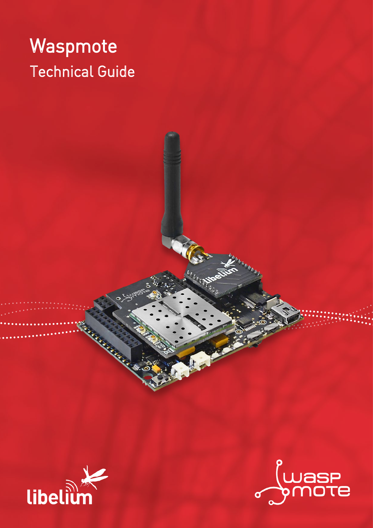
2.3. Assembly
•Connect the antenna to the wireless module
•Place the wireless module in Waspmote
•Place the wireless module in Waspmote Gateway
-11- v8.2
Waspmote Kit
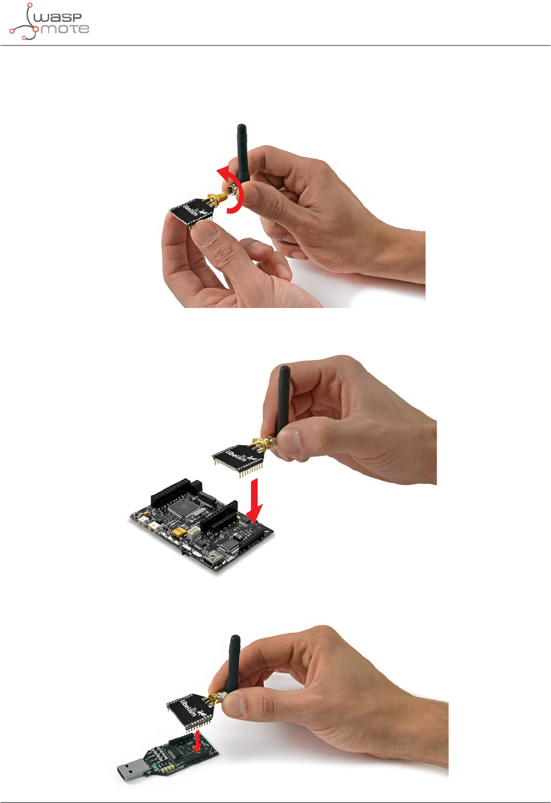
•Connect the antenna in the GPRS module
•Place the GPRS module in Waspmote
•Place the SD card in Waspmote
-12- v8.2
Waspmote Kit
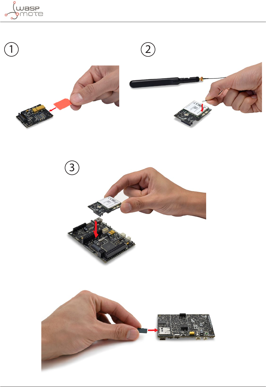
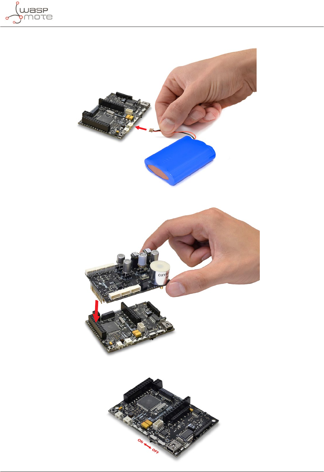
•Connect the battery in Waspmote
•Connect the sensor board
•Switch it on
-13- v8.2
Waspmote Kit
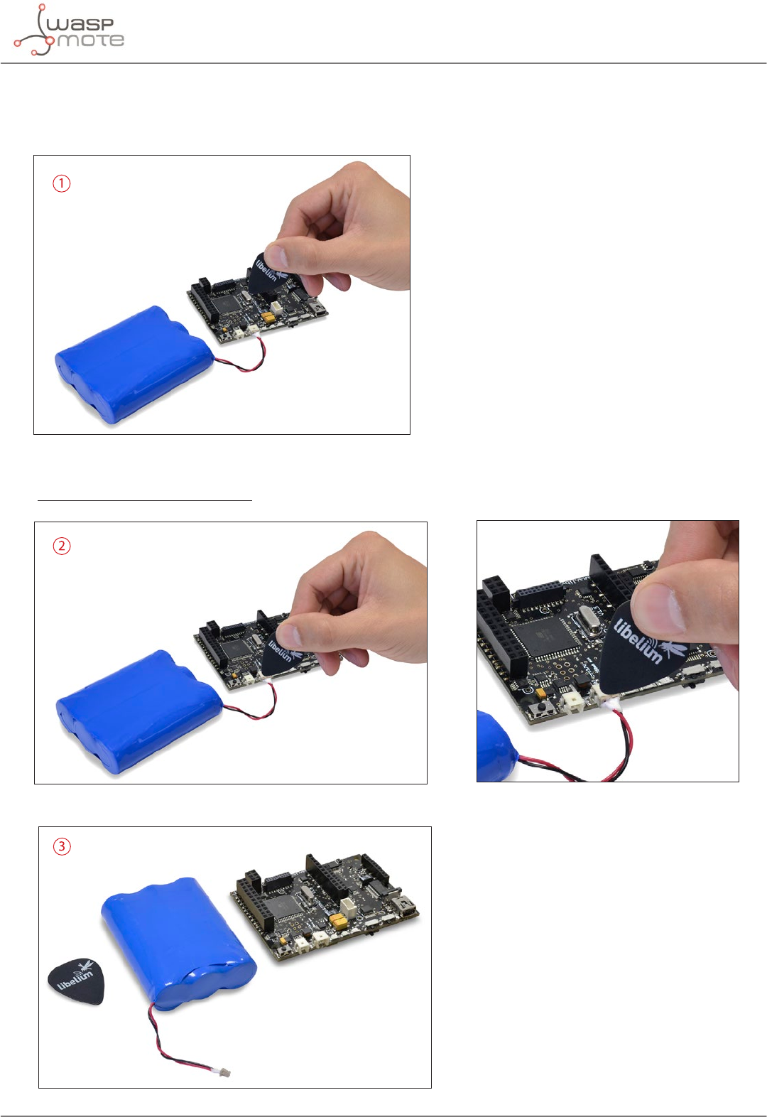
•Waspmote battery disconnection
Use the pick supplied by Libelium in order to disconnect Waspmote battery.
Insert the pick on the slot of the battery connector and pull straight out.
Do not pull the battery cables.
-14- v8.2
Waspmote Kit
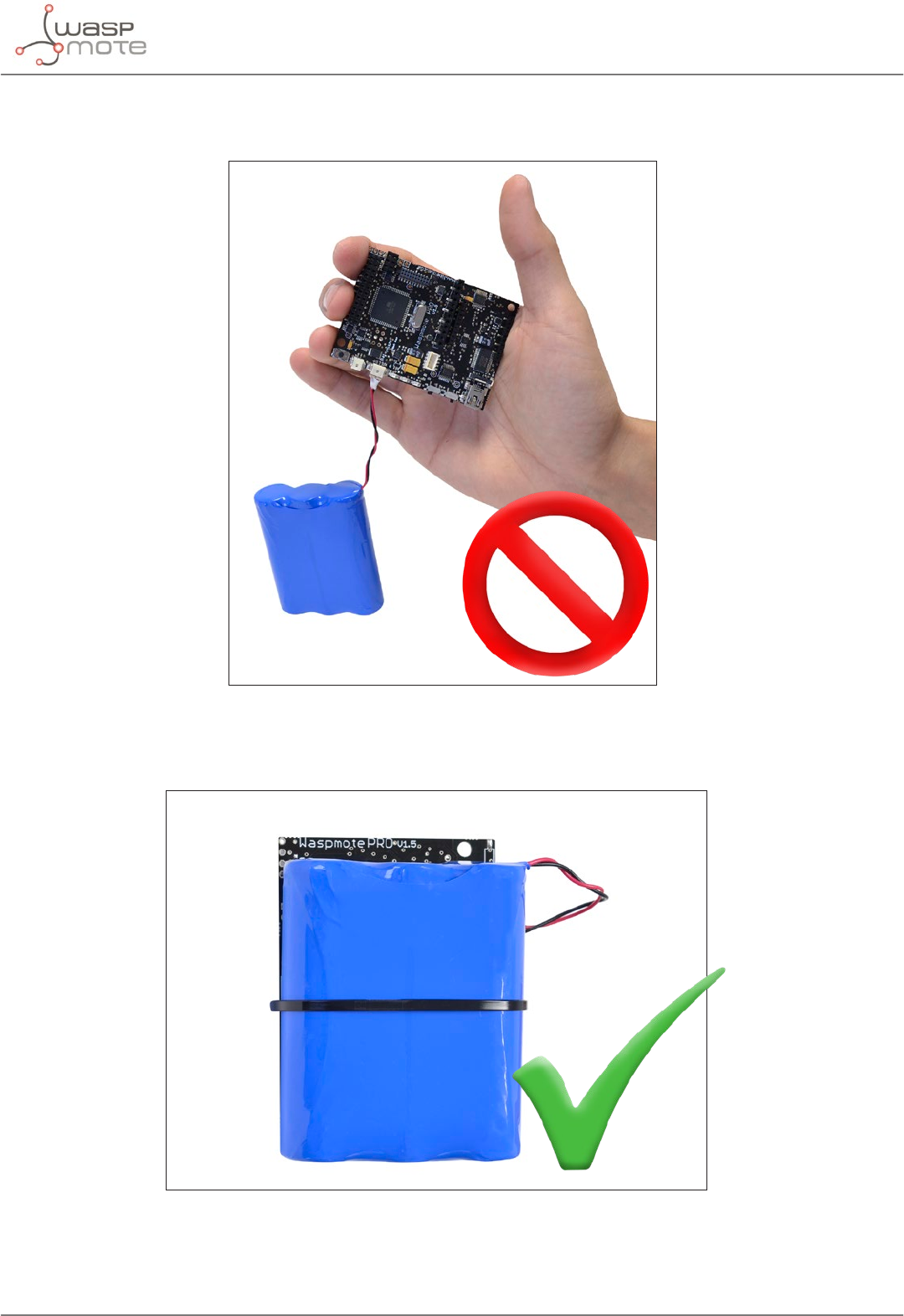
•Battery handling instructions
In order to prevent from cable breaking, avoid leaving battery freely suspended.
Use a nylon clamp in order to attach battery to Waspmote.
-15- v8.2
Waspmote Kit
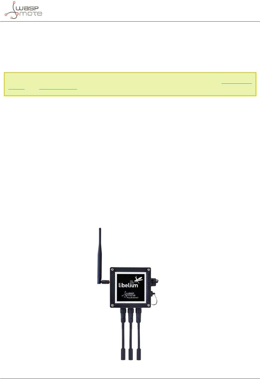
3. Waspmote Plug & Sense!
The Waspmote Plug & Sense! line allows you to easily deploy Internet of Things networks in an easy and scalable
way, ensuring minimum maintenance costs. The platform consists of a robust waterproof enclosure with specic
external sockets to connect the sensors, the solar panel, the antenna and even the USB cable in order to reprogram
the node. It has been specially designed to be scalable, easy to deploy and maintain.
Note: For a complete reference guide download the “Waspmote Plug & Sense! Technical Guide” in the Development
section of the Libelium website.
3.1. Features
•Robust waterproof IP65 enclosure
•Add or change a sensor probe in seconds
•Solar powered external panel option
•Radios available: 802.15.4, 868 MHz, 900 MHz, WiFi, 4G, Sigfox and LoRaWAN
•Over the air programming (OTAP) of multiple nodes at once (via WiFi or 4G radios)
•Special holders and brackets ready for installation in street lights and building fronts
•Graphical and intuitive interface Programming Cloud Service
•Built-in, 3-axes accelerometer
•External, contactless reset with magnet
•Optional industrial protocols: RS-485, Modbus, CAN Bus
•Optional GPS receiver
•Optional External Battery Module
•External SIM connector for the 4G models
•Fully certied: CE (Europe), FCC (USA), IC (Canada), ANATEL (Brazil), RCM (Australia), PTCRB (USA, cellular
connectivity), AT&T (USA, cellular connectivity)
Figure: Waspmote Plug & Sense!
-16- v8.2
Waspmote Kit
3.2. General view
This section shows main parts of Waspmote Plug & Sense! and a brief description of each one. In later sections
all parts will be described deeply.
3.2.1. Specications
•Material: polycarbonate
•Sealing: polyurethane
•Cover screws: stainless steel
•Ingress protection: IP65
•Impact resistance: IK08
•Rated insulation voltage AC: 690 V
•Rated insulation voltage DC: 1000 V
•Heavy metals-free: Yes
•Weatherproof: true - nach UL 746 C
•Ambient temperature (min.): -30 °C*
•Ambient temperature (max.): 70 °C*
•Approximated weight: 800 g
* Temporary extreme temperatures are supported. Regular recommended usage: -20, +60 ºC.
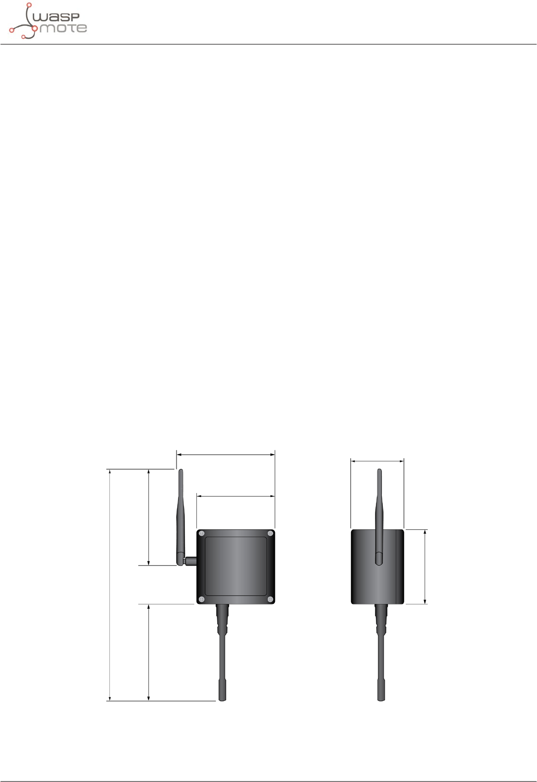
In the pictures included below it is shown a general view of Waspmote Plug & Sense! main parts. Some elements
are dedicated to node control, others are designated to sensor connection and other parts are just identication
elements. All of them will be described along this guide.
164 mm
124 mm
175 mm
410 mm
160 mm
122 mm
85 mm
Figure: Main view of Waspmote Plug & Sense!
-17- v8.2
Waspmote Kit
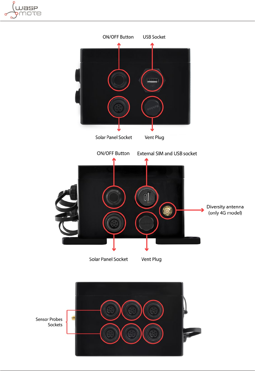
Figure: Control side of the enclosure
Control side of the enclosure for 4G model
Figure: Sensor side of the enclosure
-18- v8.2
Waspmote Kit
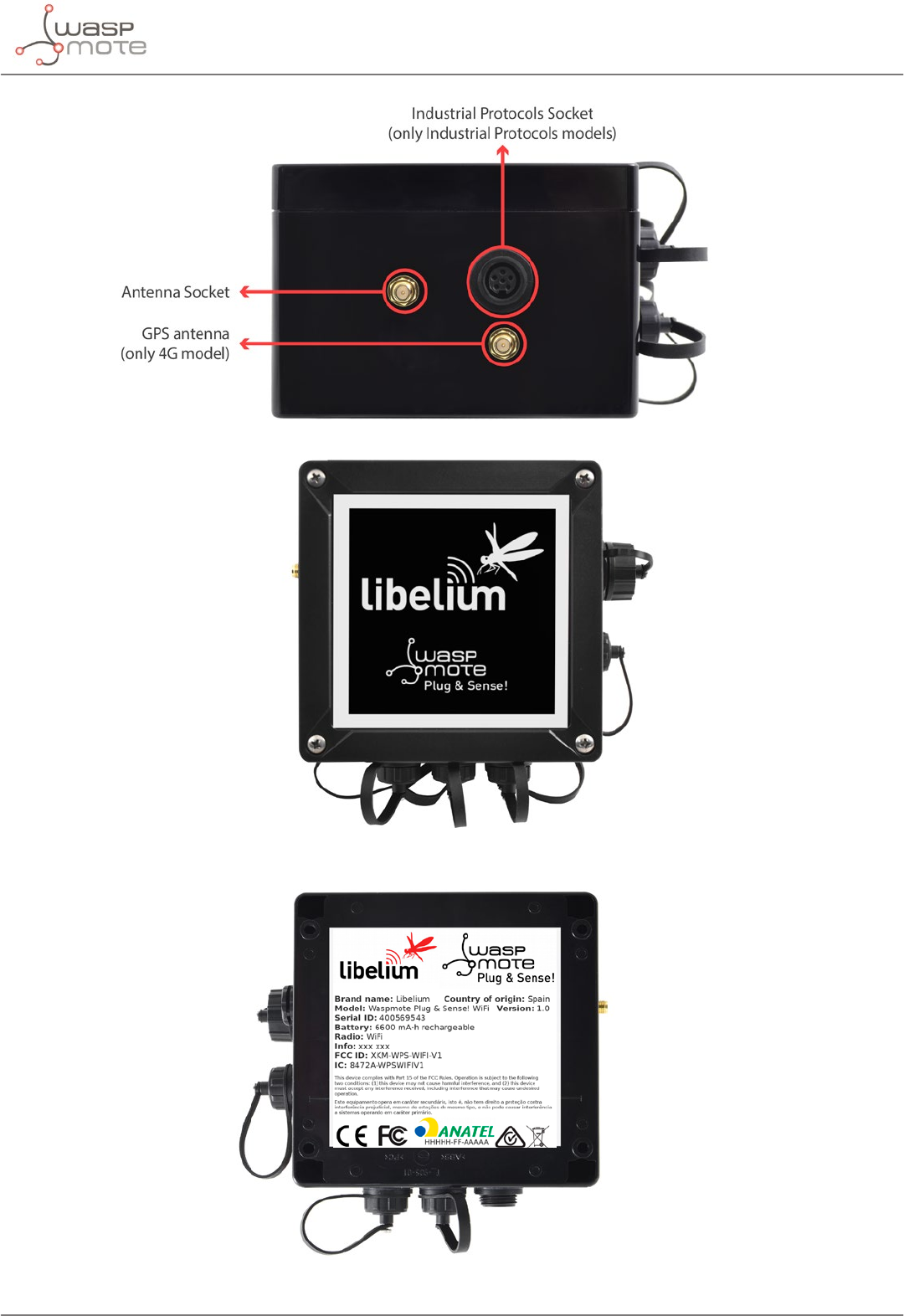
Figure: Antenna side of the enclosure
Figure: Front view of the enclosure
Figure: Back view of the enclosure
-19- v8.2
Waspmote Kit
Figure: Warranty stickers of the enclosure
Important note: Do not handle black stickers seals of the enclosure (Warranty stickers). Their integrity is the proof
that Waspmote Plug & Sense! has not been opened. If they have been handled, damaged or broken, the warranty is
automatically void.
3.2.2. Parts included
Next picture shows Waspmote Plug & Sense! and all of its elements. Some of them are optional accessories that
may not be included.
1
2
3
4
5
7
6
8
9
10
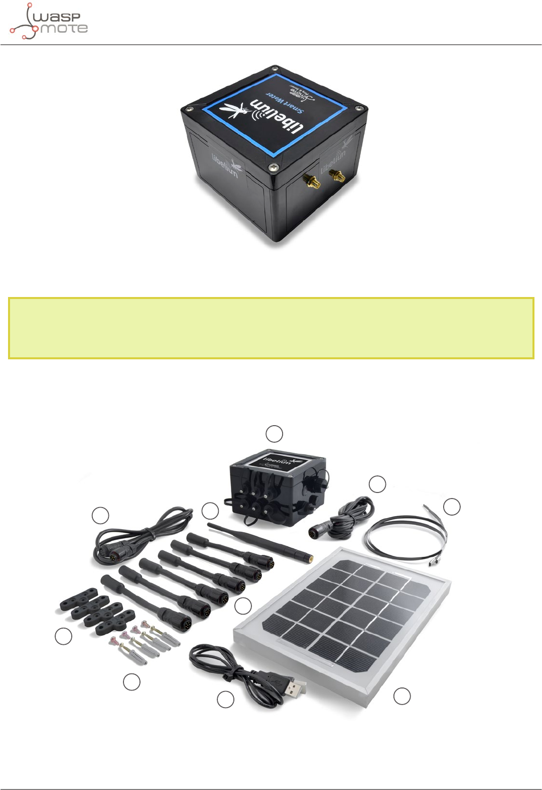
Figure: Waspmote Plug & Sense! accessories: 1 enclosure, 2 sensor probes, 3 external solar panel, 4 USB cable, 5 antenna, 6 cable ties,
7 mounting feet (screwed to the enclosure), 8 extension cord, 9 solar panel cable, 10 wall plugs & screws
-20- v8.2
Waspmote Kit
3.2.3. Identication
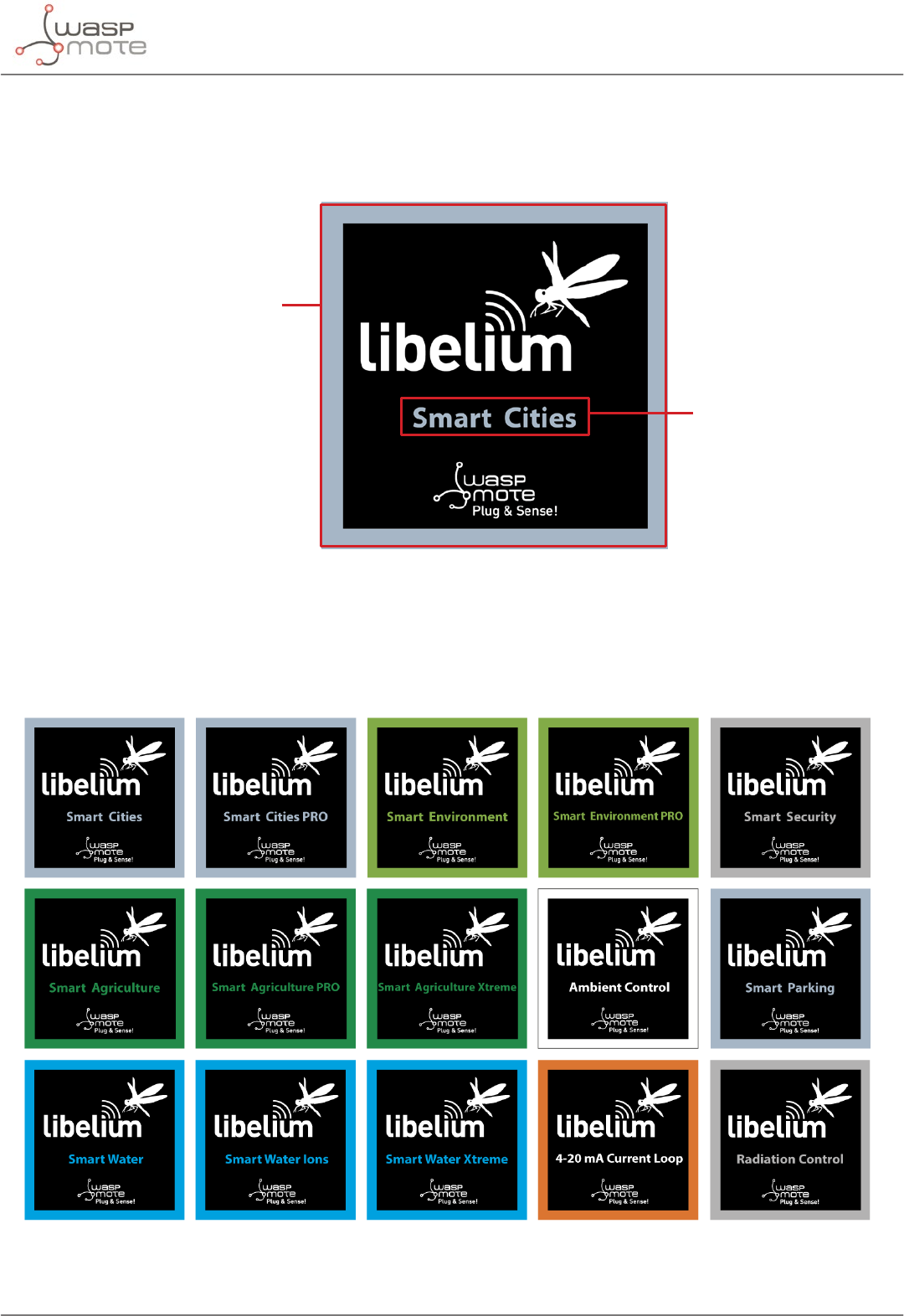
Each Waspmote model is identied by stickers. Next gure shows front sticker.
Model identication colour
Enclosure model
Figure: Front sticker of the enclosure
There are many congurations of Waspmote Plug & Sense! line, all of them identied by one unique sticker. Next
image shows all possibilities.
Figure: Different front stickers
-21- v8.2
Waspmote Kit
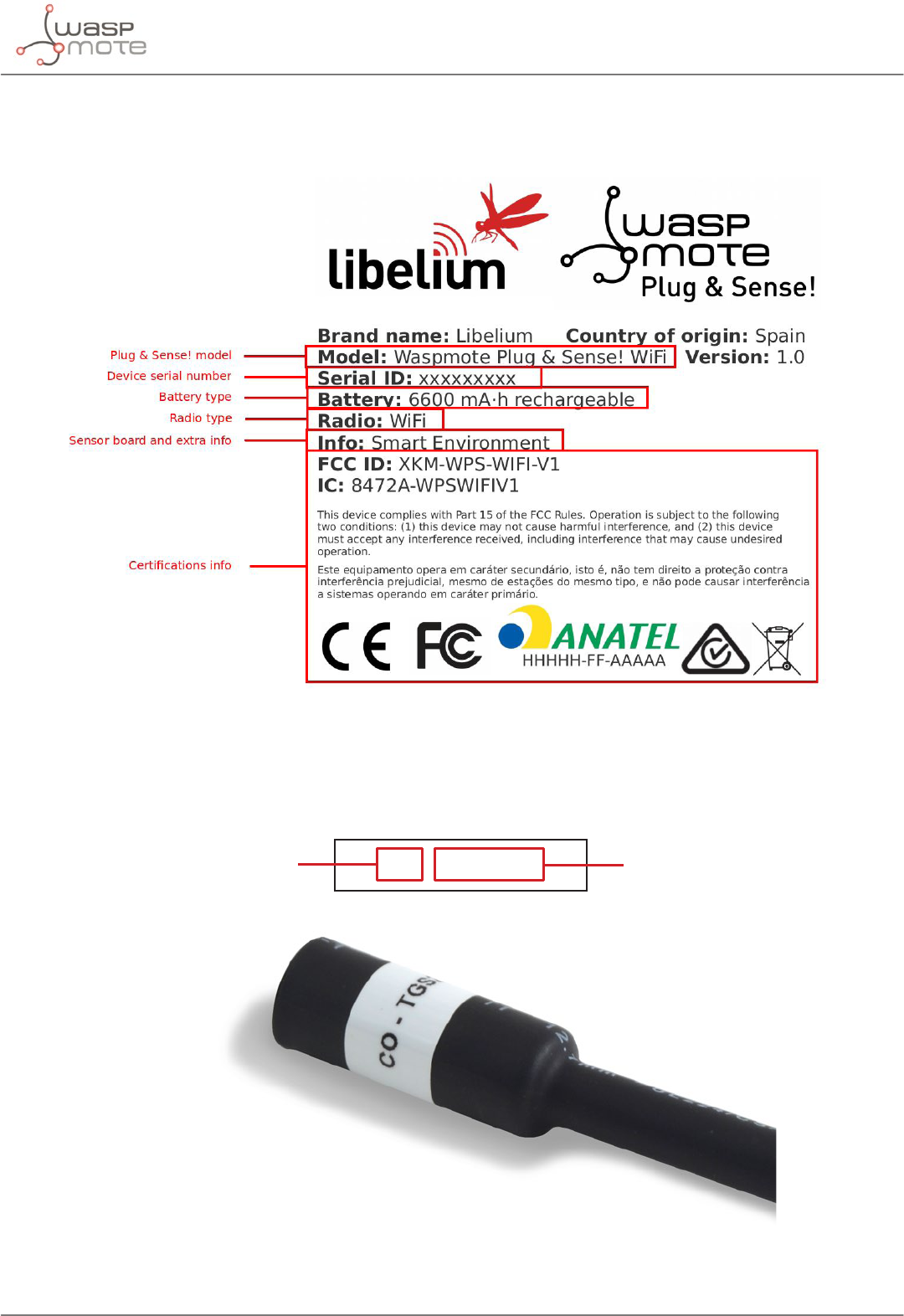
Moreover, Waspmote Plug & Sense! includes a back sticker where it is shown identication numbers, radio MAC
addresses, etc. It is highly recommended to annotate this information and save it for future maintenance. Next
gure shows it in detail.
Figure: Back sticker
Sensor probes are identied too by a sticker showing the measured parameter and the sensor manufacturer
reference.
CO - TGS2442
Measure
parameter
Sensor
reference
Figure: Sensor probe identification sticker
-22- v8.2
Waspmote Kit
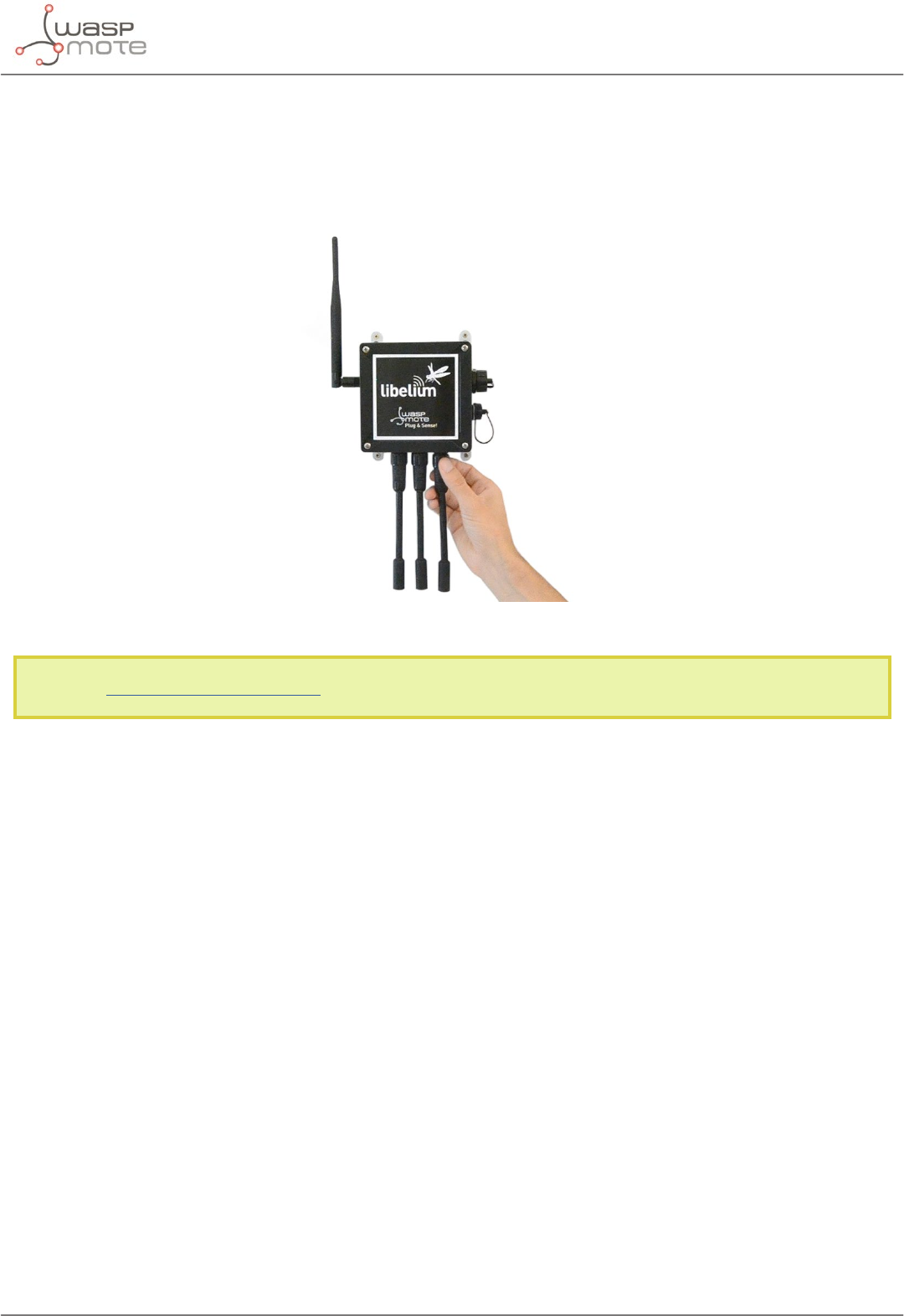
3.3. Sensor probes
Sensor probes can be easily attached by just screwing them into the bottom sockets. This allows you to add new
sensing capabilities to existing networks just in minutes. In the same way, sensor probes may be easily replaced
in order to ensure the lowest maintenance cost of the sensor network.
Figure: Connecting a sensor probe to Waspmote Plug & Sense!
Go to the Plug & Sense! Sensor Guide to know more about our sensor probes.
-23- v8.2
Waspmote Kit
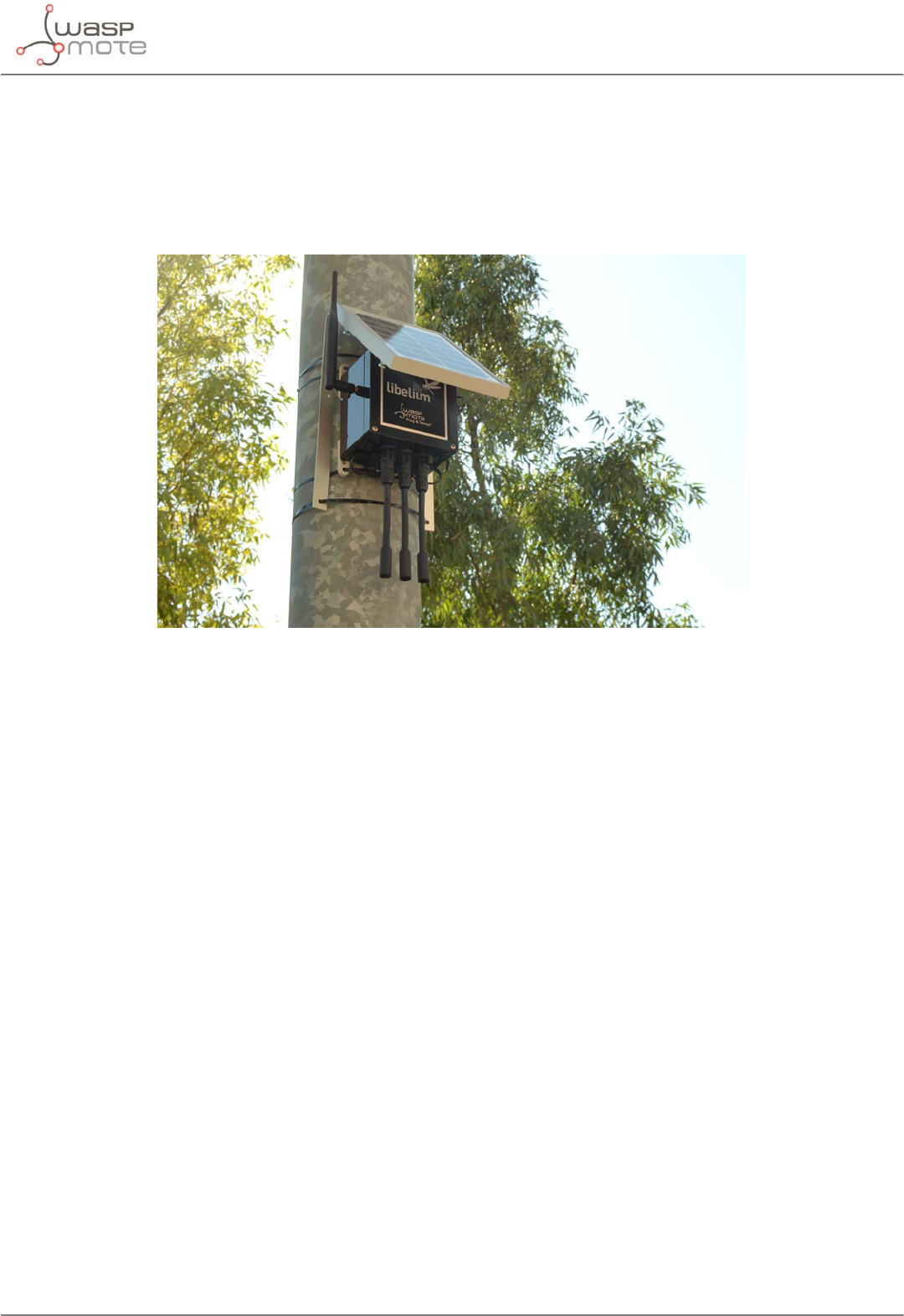
3.4. Solar powered
The battery can be recharged using the waterproof USB cable but also the external solar panel option.
The external solar panel is mounted on a 45º holder which ensures the maximum performance of each outdoor
installation.
Figure: Waspmote Plug & Sense! powered by an external solar panel
-24- v8.2
Waspmote Kit
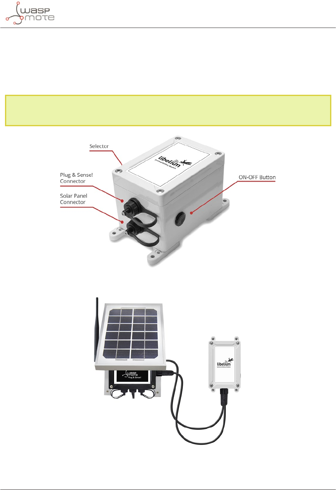
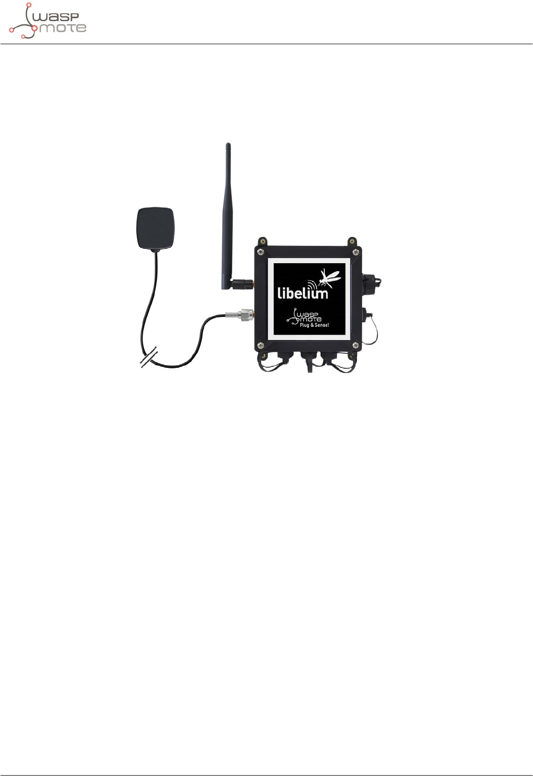
3.5. External Battery Module
The External Battery Module (EBM) is an accessory to extend the battery life of Plug & Sense!. The extension
period may be from months to years depending on the sleep cycle and radio activity. The daily charging period is
selectable among 5, 15 and 30 minutes with a selector switch and it can be combined with a solar panel to extend
even more the node’s battery lifetime.
Note: Nodes using solar panel can keep using it through the External Battery Module. The EBM is connected to
the solar panel connector of Plug & Sense! and the solar panel unit is connected to the solar panel connector
of the EBM.
Figure: Plug & Sense! with External Battery Module
Figure: Plug & Sense! with External Battery Module and solar panel
-25- v8.2
Waspmote Kit
3.6. Programming the Nodes
Waspmote Plug & Sense! can be reprogrammed in two ways:
The basic programming is done from the USB port. Just connect the USB to the specic external socket and then
to the computer to upload the new rmware.
Figure: Programming a node
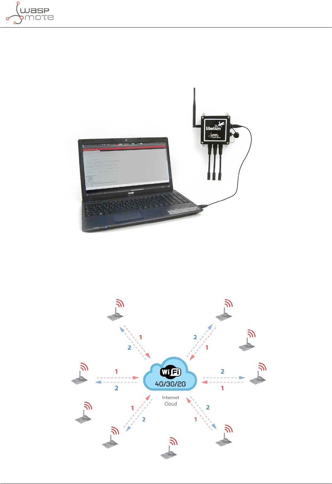
Over the Air Programming (OTAP) is also possible once the node has been installed (via WiFi or 4G radios). With
this technique you can reprogram, wireless, one or more Waspmote sensor nodes at the same time by using a
laptop and Meshlium.
Figure: Typical OTAP process
-26- v8.2
Waspmote Kit
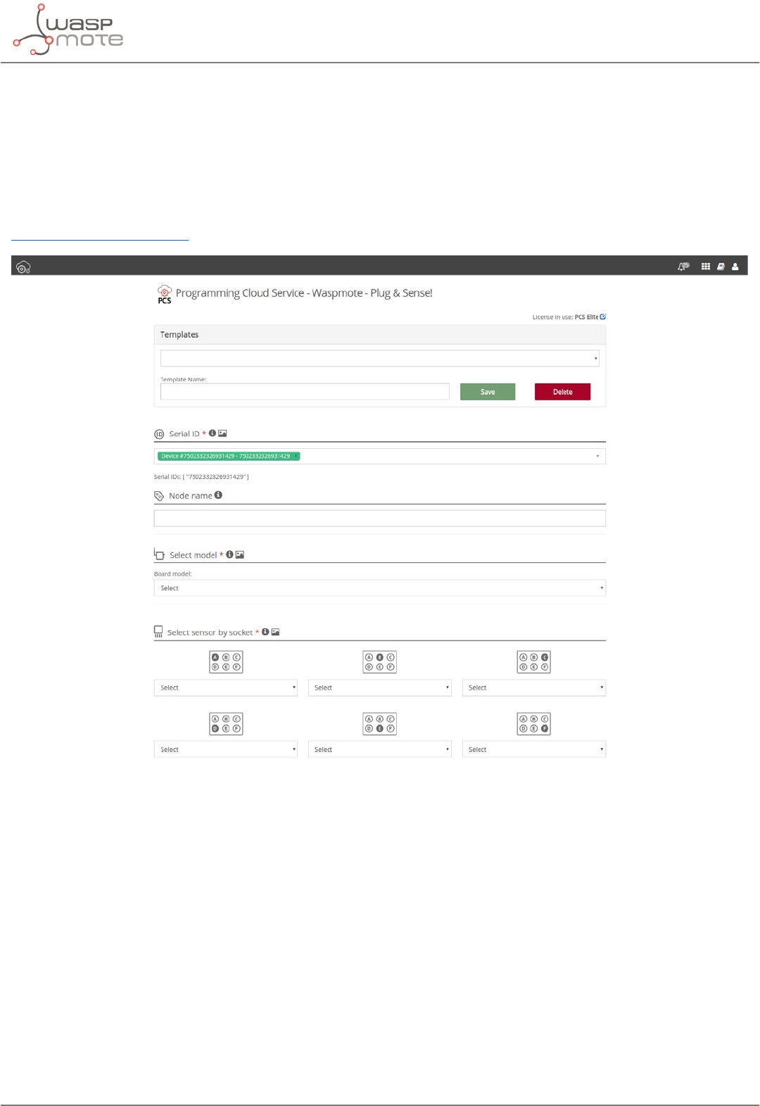
3.7. Program in minutes
The Programming Cloud Service is an intuitive graphic interface which creates code automatically. The user just
needs to to ll a web form to obtain binaries for Plug & Sense!. Advanced programming options are available,
depending on the license selected.
Check how easy it is to handle the Programming Cloud Service at:
https://cloud.libelium.com/
Figure: Programming Cloud Service

-27- v8.2
Waspmote Kit
3.8. Radio interfaces
Radio Protocol Frequency
bands
Transmission
power Sensitivity Range* Certication
XBee-PRO 802.15.4
EU 802.15.4 2.4 GHz 10 dBm -100 dBm 750 m CE
XBee-PRO 802.15.4 802.15.4 2.4 GHz 18 dBm -100 dBm 1600 m FCC, IC, ANATEL,
RCM
XBee 868LP RF 868 MHz 14 dBm -106 dBm 8.4 km CE
XBee 900HP US RF 900 MHz 24 dBm -110 dBm 15.5 km FCC, IC
XBee 900HP BR RF 900 MHz 24 dBm -110 dBm 15.5 km ANATEL
XBee 900HP AU RF 900 MHz 24 dBm -110 dBm 15.5 km RCM
WiFi
WiFi
(HTTP(S),
FTP, TCP,
UDP)
2.4 GHz 17 dBm -94 dBm 500 m CE, FCC, IC,
ANATEL, RCM
4G EU/BR
4G/3G/2G
(HTTP, FTP,
TCP, UDP)
GPS
800, 850, 900,
1800, 2100, 2600
MHz
4G: class 3
(0.2 W, 23 dBm)
4G: -102
dBm
- km - Typical
base station
range
CE, ANATEL
4G US
4G/3G/2G
(HTTP, FTP,
TCP, UDP)
GPS
700, 850, 1700,
1900 MHz
4G: class 3
(0.2 W, 23 dBm)
4G: -103
dBm
- km - Typical
base station
range
FCC, IC, PTCRB,
AT&T
4G AU
4G
(HTTP, FTP,
TCP, UDP)
700, 1800, 2600
MHz
4G: class 3
(0.2 W, 23 dBm)
4G: -102
dBm
- km - Typical
base station
range
RCM
Sigfox EU Sigfox 868 MHz 16 dBm -126 dBm
- km - Typical
base station
range
CE
Sigfox US Sigfox 900 MHz 24 dBm -127 dBm
- km - Typical
base station
range
FCC, IC
Sigfox AU / APAC /
LATAM Sigfox 900 MHz 24 dBm -127 dBm
- km - Typical
base station
range
-
LoRaWAN EU LoRaWAN 868 MHz 14 dBm -136 dBm > 15 km CE
LoRaWAN US LoRaWAN 902-928 MHz 18.5 dBm -136 dBm > 15 km FCC, IC
LoRaWAN AU LoRaWAN 915-928 MHz 18.5 dBm -136 dBm > 15 km -
LoRaWAN IN LoRaWAN 865-867 MHz 18.5 dBm -136 dBm > 15 km -
LoRaWAN ASIA-PAC
/ LATAM LoRaWAN 923 MHz 18.5 dBm -136 dBm > 15 km -
* Line of sight and Fresnel zone clearance with 5dBi dipole antenna.
-28- v8.2
Waspmote Kit
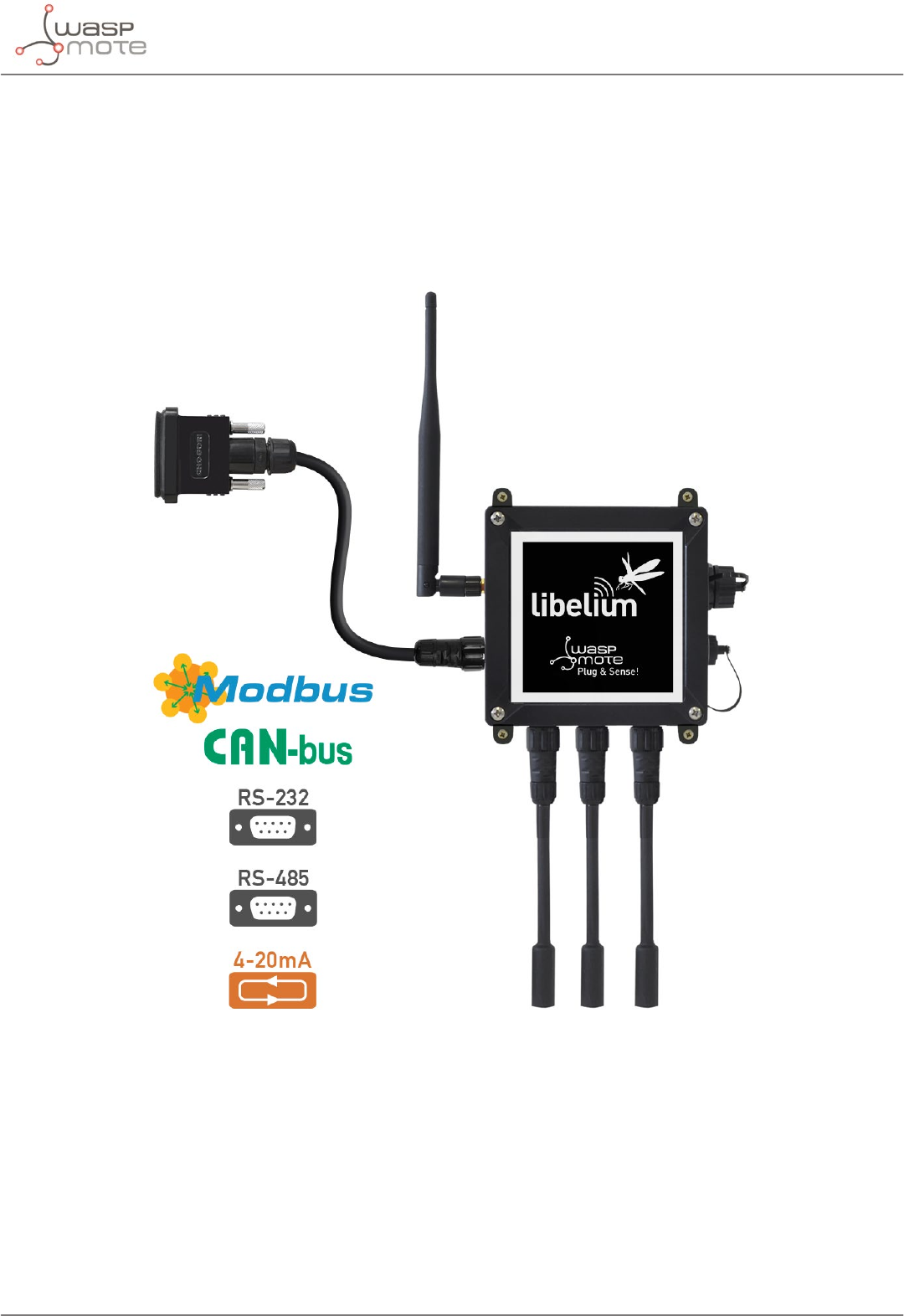
3.9. Industrial Protocols
Besides the main radio of Waspmote Plug & Sense!, it is possible to have an Industrial Protocol module as a
secondary communication option. This is oered as an accessory feature.
The available Industrial Protocols are RS-485, Modbus (software layer over RS-485) and CAN Bus. This optional
feature is accessible through an additional, dedicated socket on the antenna side of the enclosure.
Figure: Industrial Protocols available on Plug & Sense!
-29- v8.2
Waspmote Kit
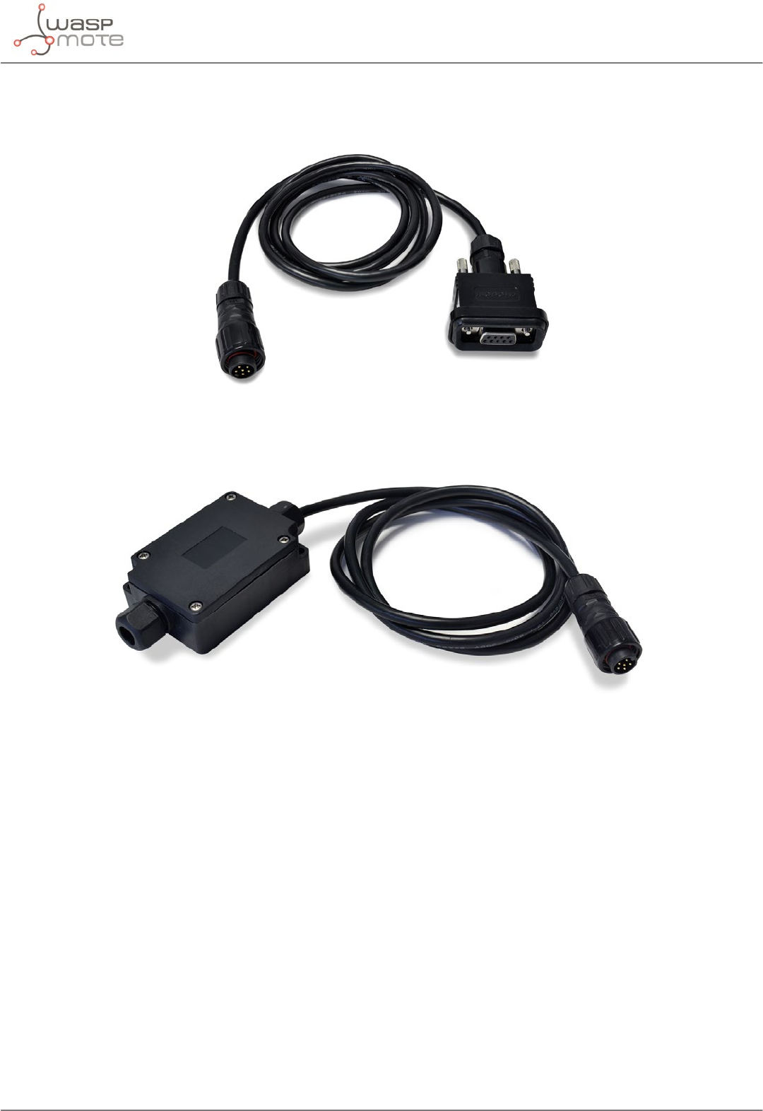
Finally, the user can choose between 2 probes to connect the desired Industrial Protocol: A standard DB9 connector
and a waterproof terminal block junction box. These options make the connections on industrial environments or
outdoor applications easier.
Figure: DB9 probe
Figure: Terminal box probe
-30- v8.2
Waspmote Kit
3.10. GPS
Any Plug & Sense! node can incorporate a GPS receiver in order to implement real-time asset tracking applications.
The user can also take advantage of this accessory to geolocate data on a map. An external, waterproof antenna
is provided; its long cable enables better installation for maximum satellite visibility.
Figure: Plug & Sense! node with GPS receiver
Chipset: JN3 (Telit)
Sensitivity:
•Acquisition: -147 dBm
•Navigation: -160 dBm
•Tracking: -163 dBm
Hot start time: <1 s
Cold start time: <35 s
Positional accuracy error < 2.5 m
Speed accuracy < 0.01 m/s
EGNOS, WAAS, GAGAN and MSAS capability
Antenna:
•Cable length: 2 m
•Connector: SMA
•Gain: 26 dBi (active)
Available information: latitude, longitude, altitude, speed, direction, date&time and ephemeris management
-31- v8.2
Waspmote Kit
3.11. Models
There are some dened congurations of Waspmote Plug & Sense! depending on which sensors are going to be
used. Waspmote Plug & Sense! congurations allow to connect up to six sensor probes at the same time.
Each model takes a dierent conditioning circuit to enable the sensor integration. For this reason each model
allows to connect just its specic sensors.
This section describes each model conguration in detail, showing the sensors which can be used in each case
and how to connect them to Waspmote. In many cases, the sensor sockets accept the connection of more than
one sensor probe. See the compatibility table for each model conguration to choose the best probe combination
for the application.
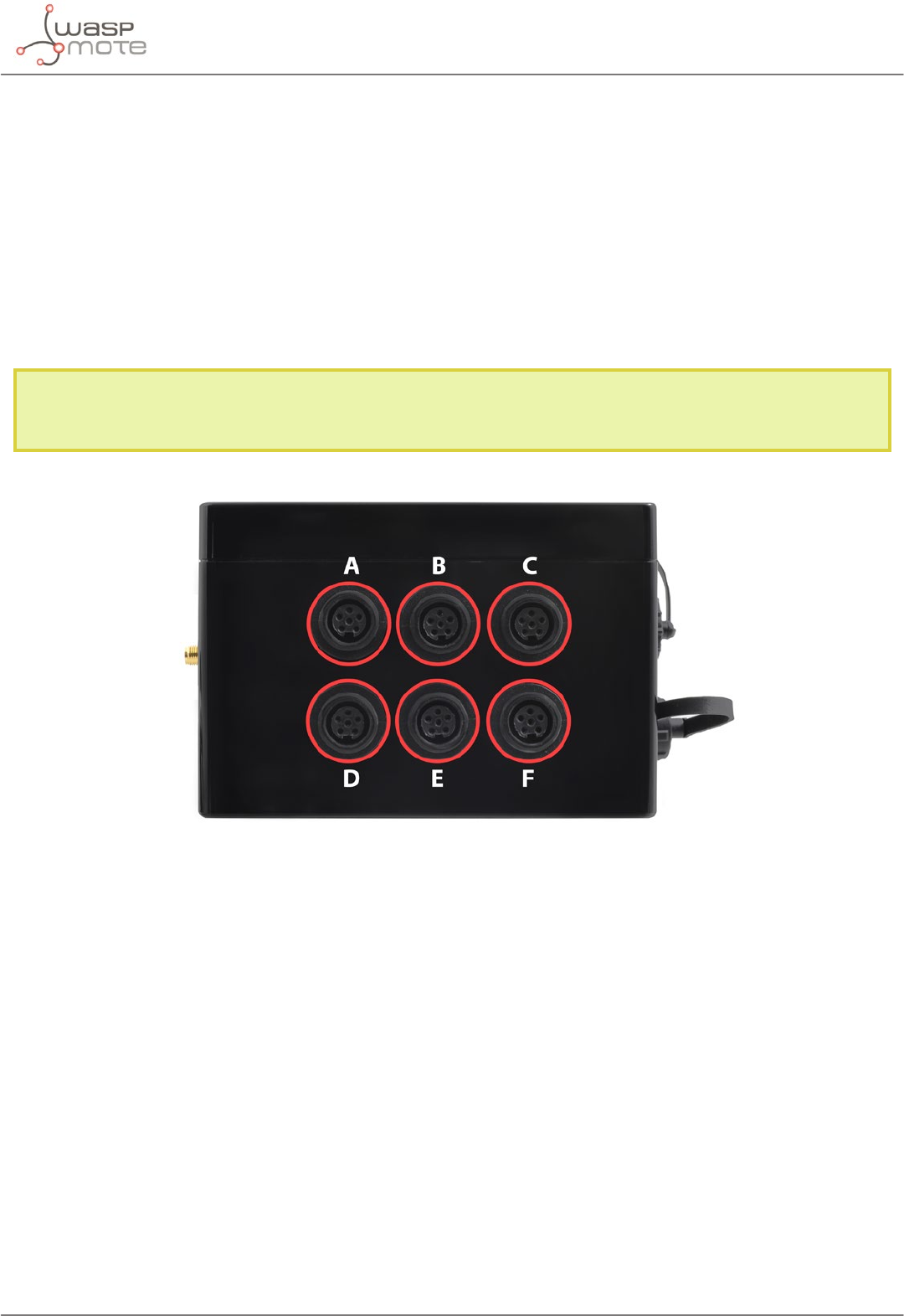
It is very important to remark that each socket is designed only for one specic sensor, so they are not
interchangeable. Always be sure you connected probes in the right socket, otherwise they can be damaged.
Figure: Identification of sensor sockets
-32- v8.2
Waspmote Kit
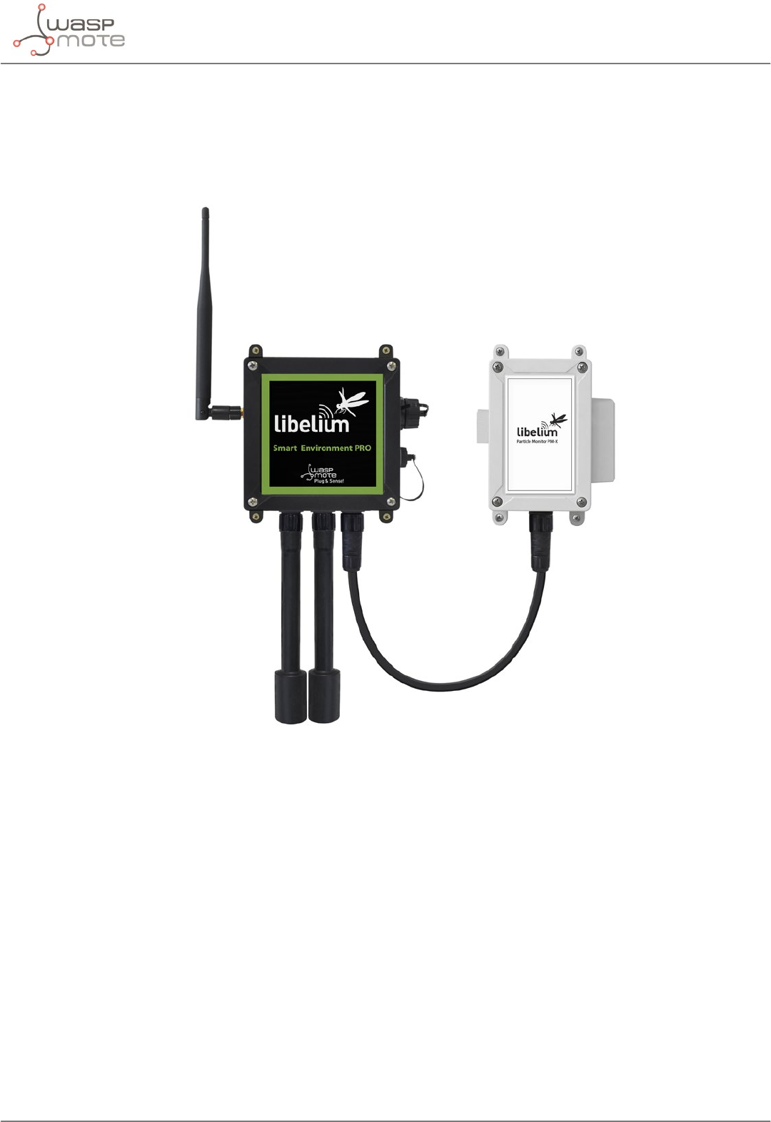
3.11.1. Smart Environment PRO
The Smart Environment PRO model has been created as an evolution of Smart Environment. It enables the user
to implement pollution, air quality, industrial, environmental or farming projects with high requirements in terms
of high accuracy, reliability and measurement range as the sensors come calibrated from factory.
Figure: Smart Environment PRO Waspmote Plug & Sense! model

-33- v8.2
Waspmote Kit
Sensor sockets are congured as shown in the gure below.
Sensor
Socket
Sensor probes allowed for each sensor socket
Parameter Reference
Carbon Monoxide (CO) for low concentrations [Calibrated] 9371-LC-P
Carbon Dioxide (CO2) [Calibrated] 9372-P
Oxygen (O2) [Calibrated] 9373-P
Ozone (O3) [Calibrated] 9374-P
Nitric Oxide (NO) for low concentrations [Calibrated] 9375-LC-P
Nitric Dioxide (NO2) high accuracy [Calibrated] 9376-HA-P
Sulfur Dioxide (SO2) high accuracy [Calibrated] 9377-HA-P
Ammonia (NH3) for low concentrations [Calibrated] 9378-LC-P
Ammonia (NH3) for high concentrations [Calibrated] 9378-HC-P
Methane (CH4) and Combustible Gas [Calibrated] 9379-P
Hydrogen (H2) [Calibrated] 9380-P
Hydrogen Sulde (H2S) [Calibrated] 9381-P
Hydrogen Chloride (HCl) [Calibrated] 9382-P
Hydrogen Cyanide (HCN) [Calibrated] 9383-P
Phosphine (PH3) [Calibrated] 9384-P
Ethylene (ETO) [Calibrated] 9385-P
Chlorine (Cl2) [Calibrated] 9386-P
D Particle Matter (PM1 / PM2.5 / PM10) - Dust 9387-P
E
Temperature, humidity and pressure 9370-P
Luminosity (Luxes accuracy) 9325-P
Ultrasound (distance measurement) 9246-P
Figure: Sensor sockets configuration for Smart Environment PRO model
Note: For more technical information about each sensor probe go to the Development section on the Libelium website.
Calibrated gas sensors are manufactured once the order has been placed to ensure maximum durability of the
calibration feature. The manufacturing process and delivery may take from 4 to 6 weeks. The lifetime of calibrated
gas sensors is 6 months working at maximum accuracy. We strongly encourage our customers to buy extra gas
sensors to replace the original ones after that time to ensure maximum accuracy and performance.
-34- v8.2
Waspmote Kit
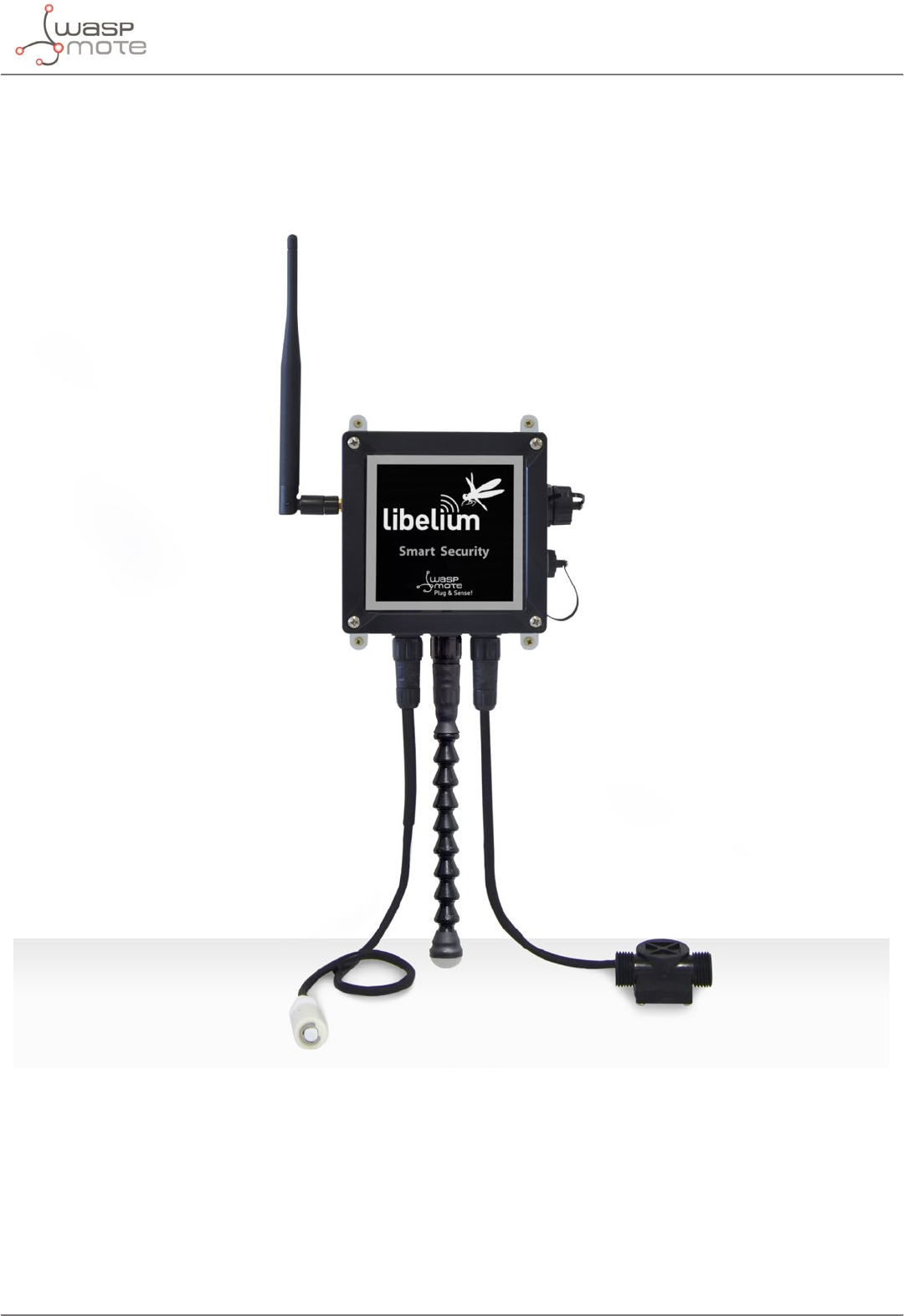
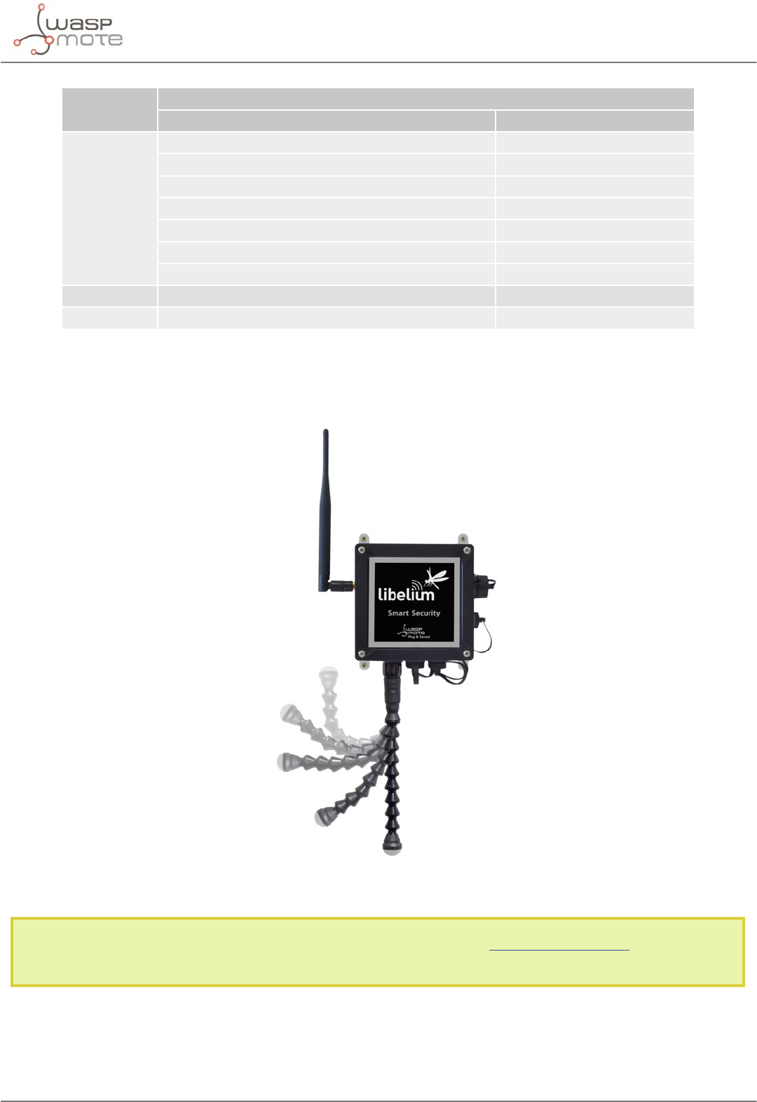
3.11.2. Smart Security
The main applications for this Waspmote Plug & Sense! conguration are perimeter access control, liquid presence
detection and doors and windows openings. Besides, a relay system allows this model to interact with external
electrical machines.
Figure: Smart Security Waspmote Plug & Sense! model
Note: The probes attached in this photo could not match the nal location. See next table for the correct conguration.
-35- v8.2
Waspmote Kit
Sensor
Socket
Sensor probes allowed for each sensor socket
Parameter Reference
A, C, D or E
Temperature + Humidity + Pressure 9370-P
Luminosity (Luxes accuracy) 9325-P
Ultrasound (distance measurement) 9246-P
Presence - PIR 9212-P
Liquid Level (combustible, water) 9239-P, 9240-P
Liquid Presence (Point, Line) 9243-P, 9295-P
Hall Eect 9207-P
B Liquid Flow (small, medium, large) 9296-P, 9297-P, 9298-P
F Relay Input-Output 9270-P
Figure: Sensor sockets configuration for Smart Security model
As we see in the gure below, thanks to the directional probe, the presence sensor probe (PIR) may be placed in
dierent positions. The sensor can be focused directly to the point we want.
Figure: Configurations of the Presence sensor probe (PIR)
Note: For more technical information about each sensor probe go to the Development section on the Libelium
website.
-36- v8.2
Waspmote Kit
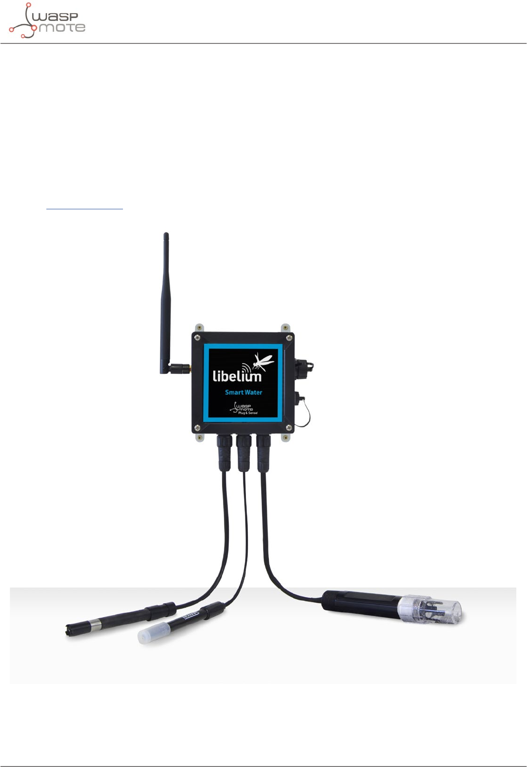
3.11.3. Smart Water
The Smart Water model has been conceived to facilitate the remote monitoring of the most relevant parameters
related to water quality. With this platform you can measure more than 6 parameters, including the most relevant
for water control such as dissolved oxygen, oxidation-reduction potential, pH, conductivity and temperature. An
extremely accurate turbidity sensor has been integrated as well.
The Smart Water Ions line is complementary for these kinds of projects, enabling the control of concentration
of ions like Ammonium (NH4
+), Bromide (Br-), Calcium (Ca2+), Chloride (Cl-), Cupric (Cu2+), Fluoride (F-), Iodide (I-),
Lithium (Li+), Magnesium (Mg2+), Nitrate (NO3
-), Nitrite (NO2
-), Perchlorate (ClO4
-), Potassium (K+), Silver (Ag+), Sodium
(Na+) and pH. Take a look to the Smart Water Ions line in the next section.
Refer to Libelium website for more information.
Figure: Smart Water Plug&Sense! model

-37- v8.2
Waspmote Kit
Sensor sockets are congured as shown in the gure below.
Sensor
Socket
Sensor probes allowed for each sensor socket
Parameter Reference
A pH 9328
B Dissolved Oxygen (DO) 9327
C Conductivity 9326
E Oxidation-Reduction Potential (ORP) 9329
FSoil/Water Temperature 9255-P (included by default)
Turbidity 9353-P
Figure: Sensor sockets configuration for Smart Water model
Note: For more technical information about each sensor probe go to the Development section on the Libelium
website.
-38- v8.2
Waspmote Kit
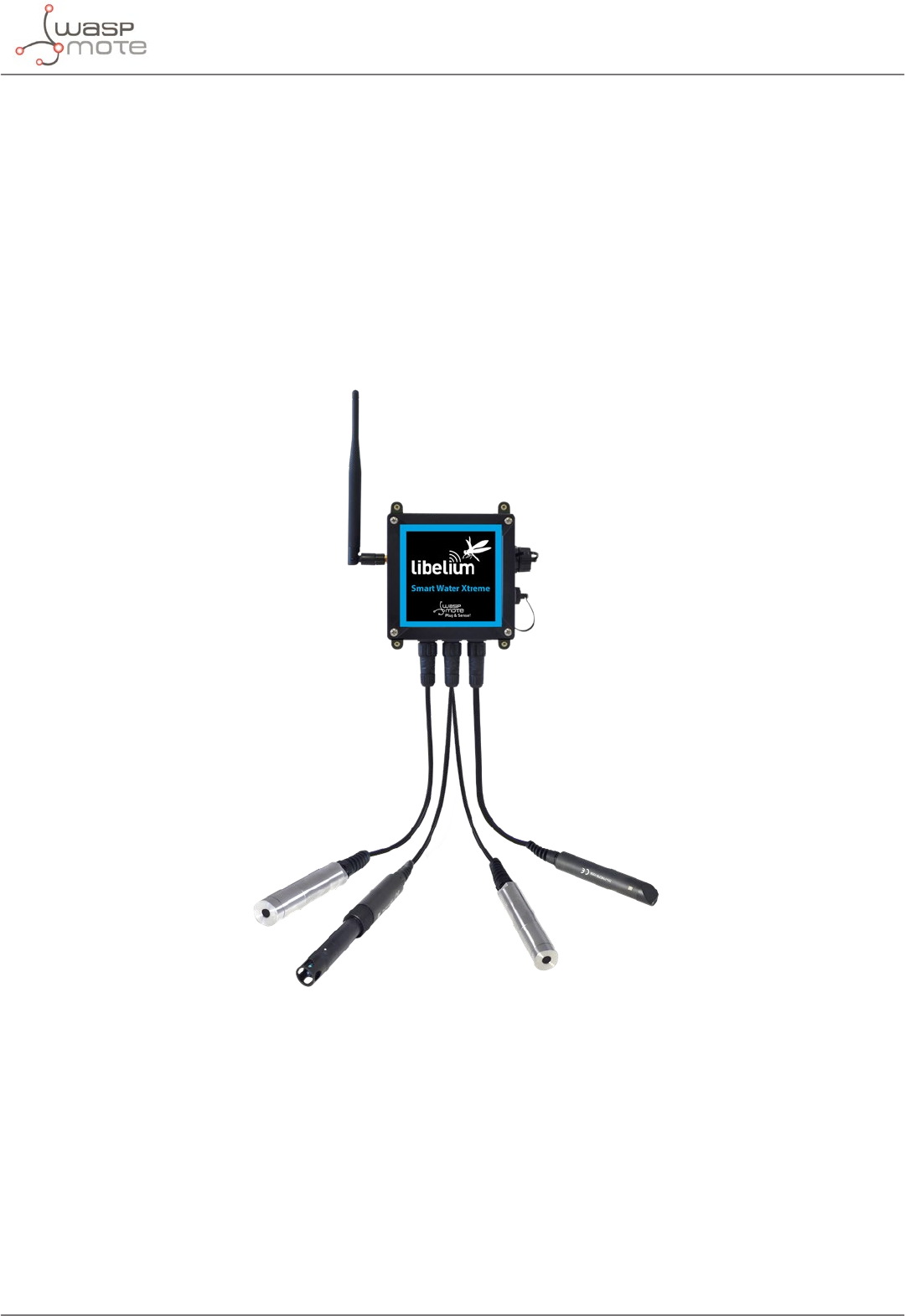
3.11.4. Smart Water Xtreme
Smart Water Xtreme was created as an evolution of Smart Water. This model integrates high-end sensors, calibrated
in factory, with enhanced accuracy and performance. Their reduced recalibration requirements and robust design
enlarge maintenance periods, making it more aordable to deploy remote Smart Water applications. This line
includes a great combination of the most signicant water parameters like dissolved oxygen, pH, oxidation-
reduction potential, conductivity, salinity, turbidity, suspended solids, sludge blanket and temperature.
Refer to Libelium website for more information.
Figure: Smart Water Xtreme Waspmote Plug & Sense! model

-39- v8.2
Waspmote Kit
Sensor sockets are congured as shown in the gure below.
Sensor Sensor probes allowed for each sensor socket
Parameter Reference
A, B, C, D and E
Optical dissolved oxygen and temperature
OPTOD 9488-P
Titanium optical dissolved oxygen and
temperature OPTOD 9489-P
pH, ORP and temperature PHEHT 9485-P
Conductivity, salinity and temperature C4E 9486-P
Inductive conductivity, salinity and
temperature CTZN 9487-P
Turbidity and temperature NTU 9353-P
Suspended solids, turbidity, sludge blanket
and temperature MES5 9490-P
A and D
Temperature, air humidity and pressure 9370-P
Luxes 9325-P
Ultrasound 9246-P
F
Manta+40 9495-P
Chlorophyll 72470
BGA 72471
Organic matter CDOM/FDOM 72472
Ammonium 72473
Nitrate 72474
Chloride 72475
Sodium 72476
Calcium 72477
Figure: Sensor sockets configuration for Smart Water Xtreme model
Note: For more technical information about each sensor probe go to the Development section on the Libelium
website.
-40- v8.2
Waspmote Kit
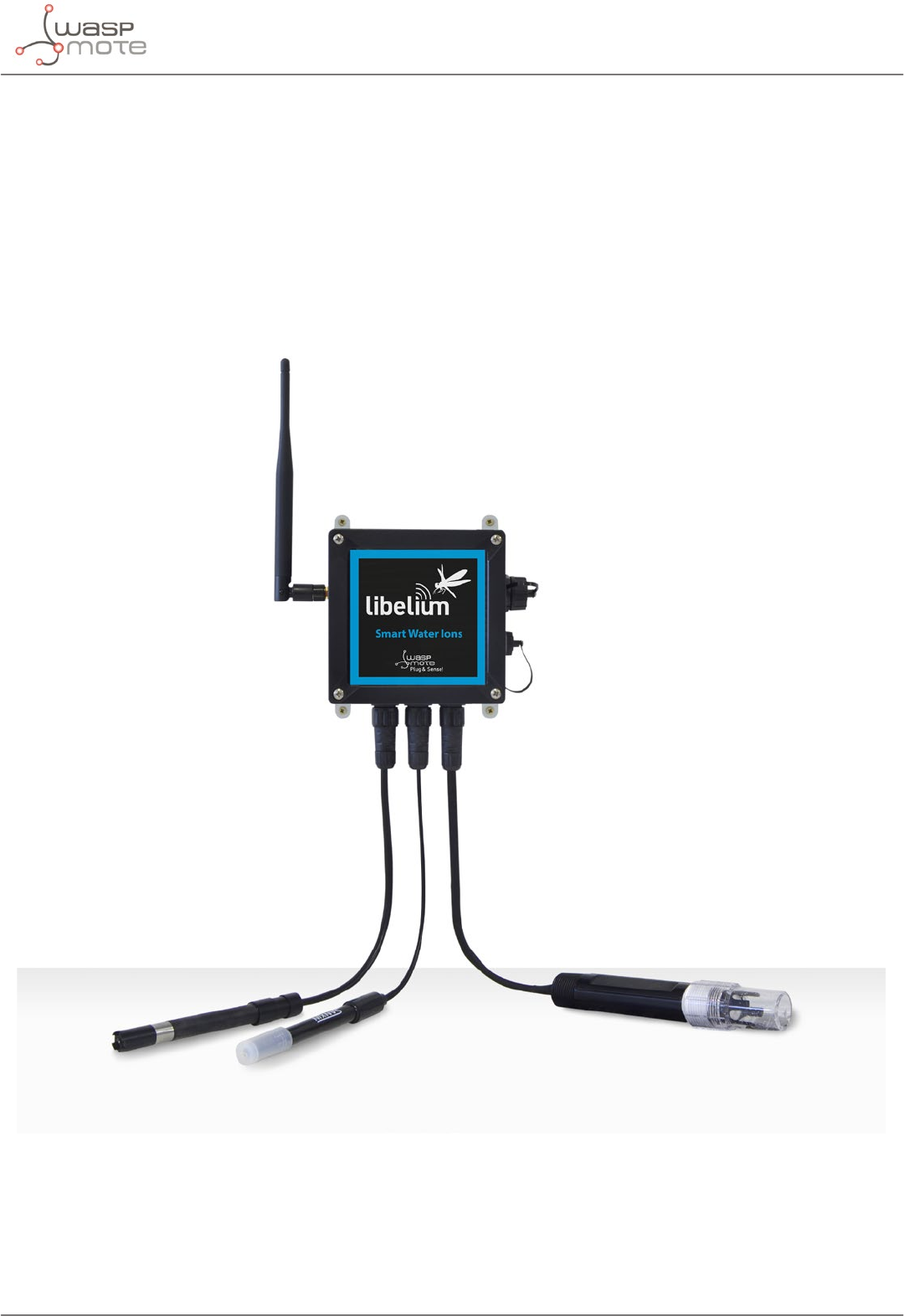
3.11.5. Smart Water Ions
The Smart Water Ions models specialize in the measurement of ions concentration for drinking water quality
control, agriculture water monitoring, swimming pools or waste water treatment.
The Smart Water line is complementary for these kinds of projects, enabling the control of parameters like
turbidity, conductivity, oxidation-reduction potential and dissolved oxygen. Take a look to the Smart Water line in
the previous section. Refer to Libelium website for more information.
There are 3 variants for Smart Water Ions: Single, Double and PRO. This is related to the type of ion sensor that
each variant can integrate. Next section describes each conguration in detail.
Figure: Smart Water Ions Waspmote Plug & Sense! model

-41- v8.2
Waspmote Kit
Single
This variant includes a Single Junction Reference Probe, so it can read all the single type ion sensors.
Sensor sockets are congured as shown in the table below.
Sensor
Socket
Sensor probes allowed for each sensor socket
Parameter Reference
A, B, C and D
Fluoride Ion (F-) 9353
Fluoroborate Ion (BF4-) 9354
Nitrate Ion (NO3
-) 9355
pH (for Smart Water Ions) 9363
E Single Junction Reference 9350 (included by default)
F Soil/Water Temperature 9255-P (included by default)
Figure: Sensor sockets configuration for Smart Water Ions model, single variant
Note: For more technical information about each sensor probe go to the Development section on the Libelium
website.
Double
This variant includes a Double Junction Reference Probe, so it can read all the double type ion sensors.
Sensor sockets are congured as shown in the table below.
Sensor
Socket
Sensor probes allowed for each sensor socket
Parameter Reference
A, B, C and D
Bromide Ion (Br-) 9356
Chloride Ion (Cl-) 9357
Cupric Ion (Cu2+) 9358
Iodide Ion (I-) 9360
Silver Ion (Ag+) 9362
pH (for Smart Water Ions) 9363
EDouble Junction Reference 9351 (included by default)
FSoil/Water Temperature 9255-P (included by default)
Figure: Sensor sockets configuration for Smart Water Ions model, double variant
Note: For more technical information about each sensor probe go to the Development section on the Libelium
website.

-42- v8.2
Waspmote Kit
Pro
This special variant integrates extreme quality sensors, with better performance than the Single or Double lines.
In this case, there is only one type of reference probe and up to 16 dierent ion parameters can be analyzed in 4
sockets.
Sensor sockets are congured as shown in the table below.
Sensor
Socket
Sensor probes allowed for each sensor socket
Parameter Reference
A, B, C or D
Ammonium Ion (NH4
+) [PRO] 9412
Bromide Ion (Br-) [PRO] 9413
Calcium Ion (Ca2+) [PRO] 9414
Chloride Ion (Cl-) [PRO] 9415
Cupric Ion (Cu2+) [PRO] 9416
Fluoride Ion (F-) [PRO] 9417
Iodide Ion (I-) [PRO] 9418
Lithium Ion (Li+) [PRO] 9419
Magnesium Ion (Mg2+) [PRO] 9420
Nitrate Ion (NO3
-) [PRO] 9421
Nitrite Ion (NO2
-) [PRO] 9422
Perchlorate Ion (ClO4
-) [PRO] 9423
Potassium Ion (K+) [PRO] 9424
Silver Ion (Ag+) [PRO] 9425
Sodium Ion (Na+) [PRO] 9426
pH [PRO] 9411
EReference Sensor Probe [PRO] 9410 (included by default)
FSoil/Water Temperature 9255-P (included by default)
Figure: Sensor sockets configuration for Smart Water Ions model, PRO variant
Note: For more technical information about each sensor probe go to the Development section on the Libelium
website.
-43- v8.2
Waspmote Kit
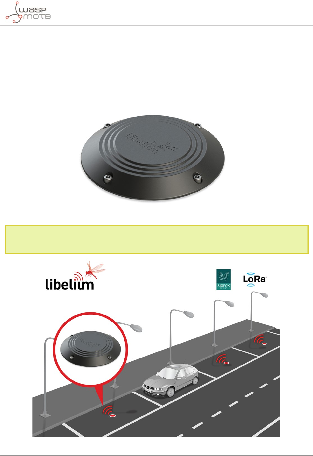
3.11.6. Smart Parking
The Smart Parking node allows to detect available parking spots by placing the node on the pavement. It works
with a magnetic sensor which detects when a vehicle is present or not.
The node benets from Sigfox and LoRaWAN technologies, getting ubiquitous coverage with few base stations.
The device is very optimized in terms of power consumption, resulting in a long battery life. Its small size and the
robust and surface-mount enclosure enables a fast installation, without the need of digging a hole in the ground.
Finally, the developer does not need to program the node, but just congure some key parameters. Remote
management and bidirectional communication allow to change parameters from the Cloud.
Figure: Smart Parking node
Note: There are specic documents for parking applications on the Libelium website. Refer to the Smart Parking
Technical Guide to see typical applications for this model and how to make a good installation.
Figure: Smart Parking application diagram
-44- v8.2
Waspmote Kit
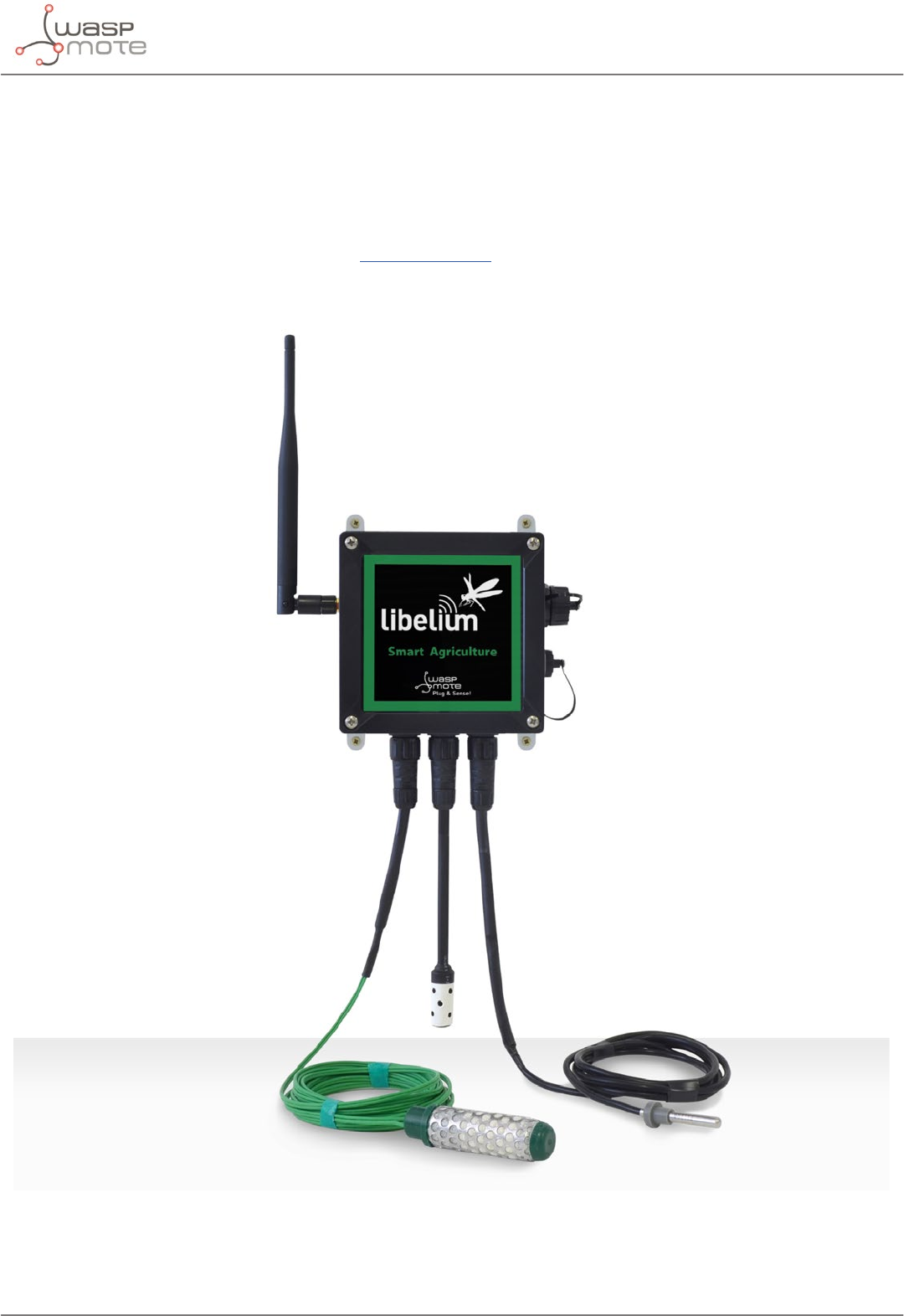
3.11.7. Smart Agriculture
The Smart Agriculture models allow to monitor multiple environmental parameters involving a wide range of
applications. It has been provided with sensors for air and soil temperature and humidity, solar visible radiation,
wind speed and direction, rainfall, atmospheric pressure, etc.
The main applications for this Waspmote Plug & Sense! model are precision agriculture, irrigation systems,
greenhouses, weather stations, etc. Refer to Libelium website for more information.
Two variants are possible for this model, normal and PRO. Next section describes each conguration in detail.
Figure: Smart Agriculture Waspmote Plug & Sense! model

-45- v8.2
Waspmote Kit
Normal
Sensor sockets are congured as shown in the gure below.
Sensor
Socket
Sensor probes allowed for each sensor socket
Parameter Reference
AWeather Station WS-3000 (anemometer + wind vane +
pluviometer) 9256-P
B Soil Moisture 1 9248-P, 9324-P, 9323-P
C Soil Moisture 3 9248-P, 9324-P, 9323-P
D
Soil Temperature 86949-P
Temperature + Humidity + Pressure 9370-P
Luminosity (Luxes accuracy) 9325-P
Ultrasound (distance measurement) 9246-P
ELeaf Wetness 9249-P
Soil Moisture 2 9248-P, 9324-P, 9323-P
F (digital
bus)
Temperature + Humidity + Pressure 9370-P
Luminosity (Luxes accuracy) 9325-P
Ultrasound (distance measurement) 9246-P
Figure: Sensor sockets configuration for Smart Agriculture model
Note: For more technical information about each sensor probe go to the Development section on the Libelium
website.

-46- v8.2
Waspmote Kit
PRO
Sensor sockets are congured as shown in the gure below.
Sensor
Socket
Sensor probes allowed for each sensor socket
Parameter Reference
A Weather Station WS-3000 (anemometer + wind vane + pluviometer) 9256-P
B
Soil Moisture 1 9248-P, 9324-P, 9323-P
Solar Radiation (PAR) 9251-P
Ultraviolet Radiation 9257-P
CSoil Moisture 3 9248-P, 9324-P, 9323-P
Dendrometers 9252-P, 9253-P, 9254-P
D (digital
bus)
Soil Temperature (Pt-1000) 9255-P
Temperature + Humidity + Pressure 9370-P
Luminosity (Luxes accuracy) 9325-P
Ultrasound (distance measurement) 9246-P
ELeaf Wetness 9249-P
Soil Moisture 2 9248-P, 9324-P, 9323-P
F (digital
bus)
Temperature + Humidity + Pressure 9370-P
Luminosity (Luxes accuracy) 9325-P
Ultrasound (distance measurement) 9246-P
Figure: Sensor sockets configuration for Smart Agriculture PRO model
* Ask Libelium Sales Department for more information.
Note: For more technical information about each sensor probe go to the Development section on the Libelium
website.
-47- v8.2
Waspmote Kit
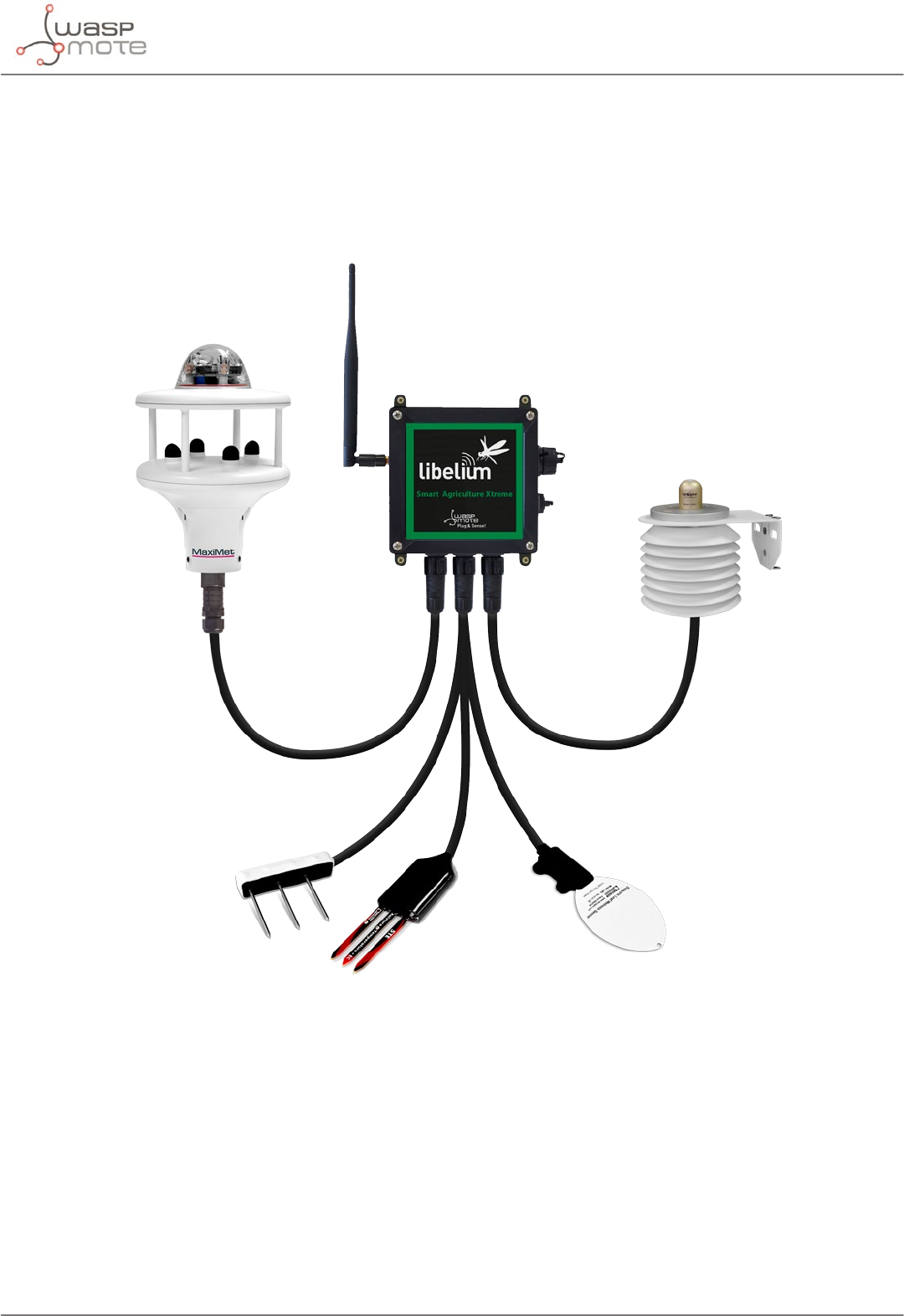
3.11.8. Smart Agriculture Xtreme
The Plug & Sense! Smart Agriculture Xtreme is an evolution of our Agriculture line with a new selection of high-
end professional sensors. It allows to monitor multiple environmental parameters involving a wide range of
applications, from plant growing analysis to weather observation. There are sensors for atmospheric and soil
monitoring and plants health. Up to 32 sensors can be connected.
Figure: Smart Agriculture Xtreme Waspmote Plug & Sense! model

-48- v8.2
Waspmote Kit
Sensor sockets are congured as shown in the gure below.
Sensor
Socket
Sensor probes allowed for each sensor socket
Parameter Reference
A and D
Non-contact surface temperature measurement SI-411 9468-P
Leaf and ower bud temperature SF-421 9467-P
Soil oxygen level SO-411 9469-P
Conductivity, water content and soil temperature 5TE 9402-P
Conductivity, water content and soil temperature GS3 9464-P
Soil temperature and volumetric water content 5TM 9460-P
Soil water potential MPS-6 9465-P
Vapor pressure, humidity, temperature, and atmospheric
pressure in soil and air VP-4 9471-P
Temperature, air humidity and pressure 9370-P
Luxes 9325-P
Ultrasound 9246-P
B
Non-contact surface temperature measurement SI-411 9468-P
Leaf and ower bud temperature SF-421 9467-P
Soil oxygen level SO-411 9469-P
Conductivity, water content and soil temperature 5TE 9402-P
Conductivity, water content and soil temperature GS3 9464-P
Soil temperature and volumetric water content 5TM 9460-P
Soil water potential MPS-6 9465-P
Vapor pressure, humidity, temperature, and atmospheric
pressure in soil and air VP-4 9471-P
Leaf wetness Phytos 31 9466-P
Shortwave radiation SP-510 9470-P
Solar radiation (PAR) SQ-110 for Smart Agriculture Xtreme 9251-PX
Ultraviolet radiation SU-100 for Smart Agriculture Xtreme 9257-PX
4-20 mA type (generic) -
C
Non-contact surface temperature measurement SI-411 9468-P
Leaf and ower bud temperature SF-421 9467-P
Soil oxygen level SO-411 9469-P
Conductivity, water content and soil temperature 5TE 9402-P
Conductivity, water content and soil temperature GS3 9464-P
Soil temperature and volumetric water content 5TM 9460-P
Soil water potential MPS-6 9465-P
Vapor pressure, humidity, temperature, and atmospheric
pressure in soil and air VP-4 9471-P
Dendrometers (DC2, DD-S, DF) for Smart Agriculture Xtreme 9252-PX, 9253-PX, 9254-PX
Shortwave radiation SP-510 9470-P
Solar radiation (PAR) SQ-110 for Smart Agriculture Xtreme 9251-PX
Ultraviolet radiation SU-100 for Smart Agriculture Xtreme 9257-PX

-49- v8.2
Waspmote Kit
E
Shortwave radiation SP-510 9470-P
Solar radiation (PAR) SQ-110 for Smart Agriculture Xtreme 9251-PX
Ultraviolet radiation SU-100 for Smart Agriculture Xtreme 9257-PX
Weather station GMX-100 (PO) Probe 9472-P
Weather station GMX-101 (R) 9473-P
Weather station GMX-200 (W) 9474-P
Weather station GMX-240 (W-PO) 9463-P
Weather station GMX-300 (T-H-AP) 9475-P
Weather station GMX-301 (T-H-AP-R) 9476-P
Weather station GMX-400 (PO-T-H-AP) 9477-P
Weather station GMX-500 (W-T-H-AP) 9478-P
Weather station GMX-501 (W-T-H-AP-R) 9479-P
Weather station GMX-531 (W-PT-T-H-AP-R) 9480-P
Weather station GMX-541 (W-PO-T-H-AP-R) 9481-P
Weather station GMX-550 (W-x-T-H-AP) 9482-P
Weather station GMX-551 (W-x-T-H-AP-R) 9483-P
Weather station GMX-600 (W-PO-T-H-AP) 9484-P
F
Shortwave radiation SP-510 9470-P
Solar radiation (PAR) SQ-110 for Smart Agriculture Xtreme 9251-PX
Ultraviolet radiation SU-100 for Smart Agriculture Xtreme 9257-PX
RS-232 type (generic) -
4-20 mA type (generic) -
Figure: Sensor sockets configuration for Smart Agriculture model
Note: For more technical information about each sensor probe go to the Development section on the Libelium
website.
-50- v8.2
Waspmote Kit
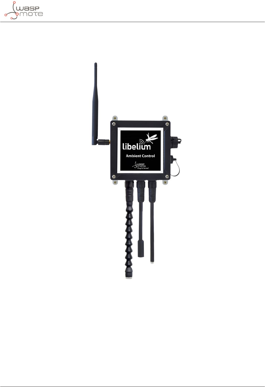
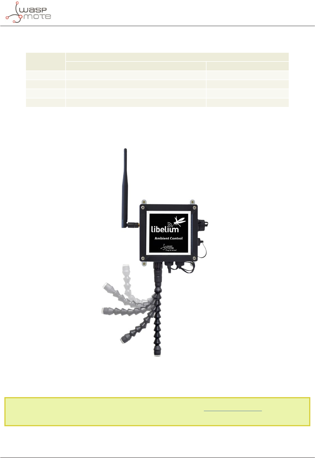
3.11.9. Ambient Control
This model is designed to monitor the main environment parameters easily. Only three sensor probes are allowed
for this model, as shown in next table.
Figure: Ambient Control Waspmote Plug & Sense! model
-51- v8.2
Waspmote Kit
Sensor sockets are congured as it is shown in gure below.
Sensor
Socket
Sensor probes allowed for each sensor socket
Parameter Reference
A Temperature + Humidity + Pressure 9370-P
B Luminosity (LDR) 9205-P
C Luminosity (Luxes accuracy) 9325-P
D, E and F Not used -
Figure: Sensor sockets configuration for Ambient Control model
As we see in the gure below, thanks to the directional probe, the Luminosity (Luxes accuracy) sensor probe may
be placed in dierent positions. The sensor can be focused directly to the light source we want to measure.
Figure: Configurations of the Luminosity sensor probe (luxes accuracy)
Note: For more technical information about each sensor probe go to the Development section on the Libelium
website.
-52- v8.2
Waspmote Kit
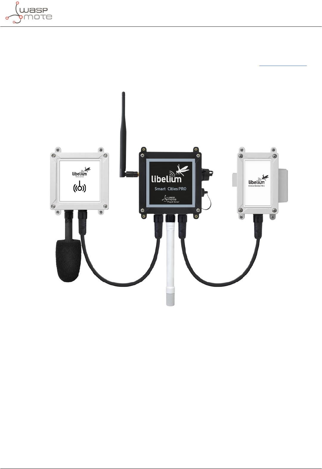
3.11.10. Smart Cities PRO
The main applications for this Waspmote Plug & Sense! model are noise maps (monitor in real time the acoustic
levels in the streets of a city), air quality, waste management, smart lighting, etc. Refer to Libelium website for
more information.
Figure: Smart Cities PRO Waspmote Plug & Sense! model

-53- v8.2
Waspmote Kit
Sensor sockets are congured as shown in the gure below.
Sensor
Socket
Sensor probes allowed for each sensor socket
Parameter Reference
A
Noise level sensor NLS
Temperature + Humidity + Pressure 9370-P
Luminosity (Luxes accuracy) 9325-P
Ultrasound (distance measurement) 9246-P
Carbon Monoxide (CO) for low concentrations
[Calibrated] 9371-LC-P
Carbon Dioxide (CO2) [Calibrated] 9372-P
Oxygen (O2) [Calibrated] 9373-P
Ozone (O3) [Calibrated] 9374-P
Nitric Oxide (NO) for low concentrations [Calibrated] 9375-LC-P
Nitric Dioxide (NO2) high accuracy [Calibrated] 9376-HA-P
Sulfur Dioxide (SO2) high accuracy [Calibrated] 9377-HA-P
Ammonia (NH3) for low concentrations [Calibrated] 9378-LC-P
Ammonia (NH3) for high concentrations [Calibrated] 9378-HC-P
Methane (CH4) and Combustible Gas [Calibrated] 9379-P
Hydrogen (H2) [Calibrated] 9380-P
Hydrogen Sulde (H2S) [Calibrated] 9381-P
Hydrogen Chloride (HCl) [Calibrated] 9382-P
Hydrogen Cyanide (HCN) [Calibrated] 9383-P
Phosphine (PH3) [Calibrated] 9384-P
Ethylene (ETO) [Calibrated] 9385-P
Chlorine (Cl2) [Calibrated] 9386-P
Temperature + Humidity + Pressure 9370-P
Luminosity (Luxes accuracy) 9325-P
Ultrasound (distance measurement) 9246-P
D Particle Matter (PM1 / PM2.5 / PM10) - Dust 9387-P
E
Temperature + Humidity + Pressure 9370-P
Luminosity (Luxes accuracy) 9325-P
Ultrasound (distance measurement) 9246-P
Figure: Sensor sockets configuration for Smart Cities PRO model
Note: For more technical information about each sensor probe go to the Development section in Libelium website.
Calibrated gas sensors are manufactured once the order has been placed to ensure maximum durability of the
calibration feature. The manufacturing process and delivery may take from 4 to 6 weeks. The lifetime of calibrated
gas sensors is 6 months working at maximum accuracy. We strongly encourage our customers to buy extra gas
sensors to replace the original ones after that time to ensure maximum accuracy and performance.
-54- v8.2
Waspmote Kit
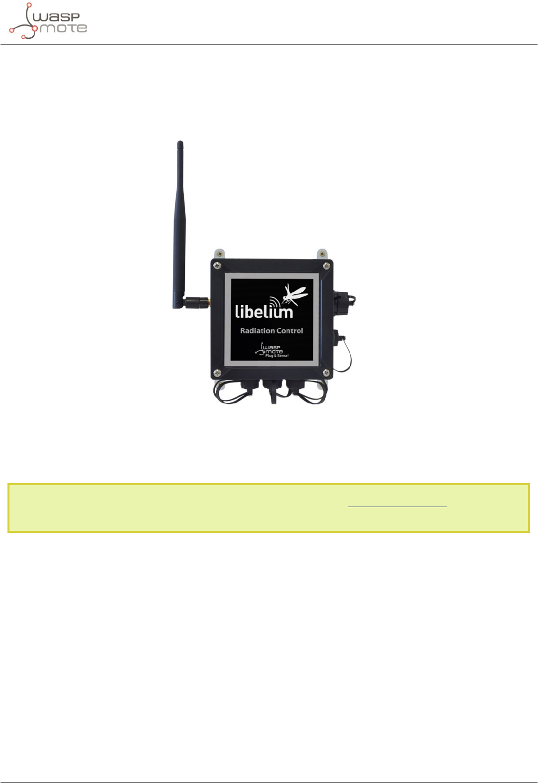
3.11.11. Radiation Control
The main application for this Waspmote Plug & Sense! conguration is to measure radiation levels using a Geiger
sensor. For this model, the Geiger tube is already included inside Waspmote, so the user does not have to connect
any sensor probe to the enclosure. The rest of the other sensor sockets are not used.
Figure: Radiation Control Waspmote Plug & Sense! model
Sensor sockets are not used for this model.
Note: For more technical information about each sensor probe go to the Development section on the Libelium
website.
-55- v8.2
Waspmote Kit
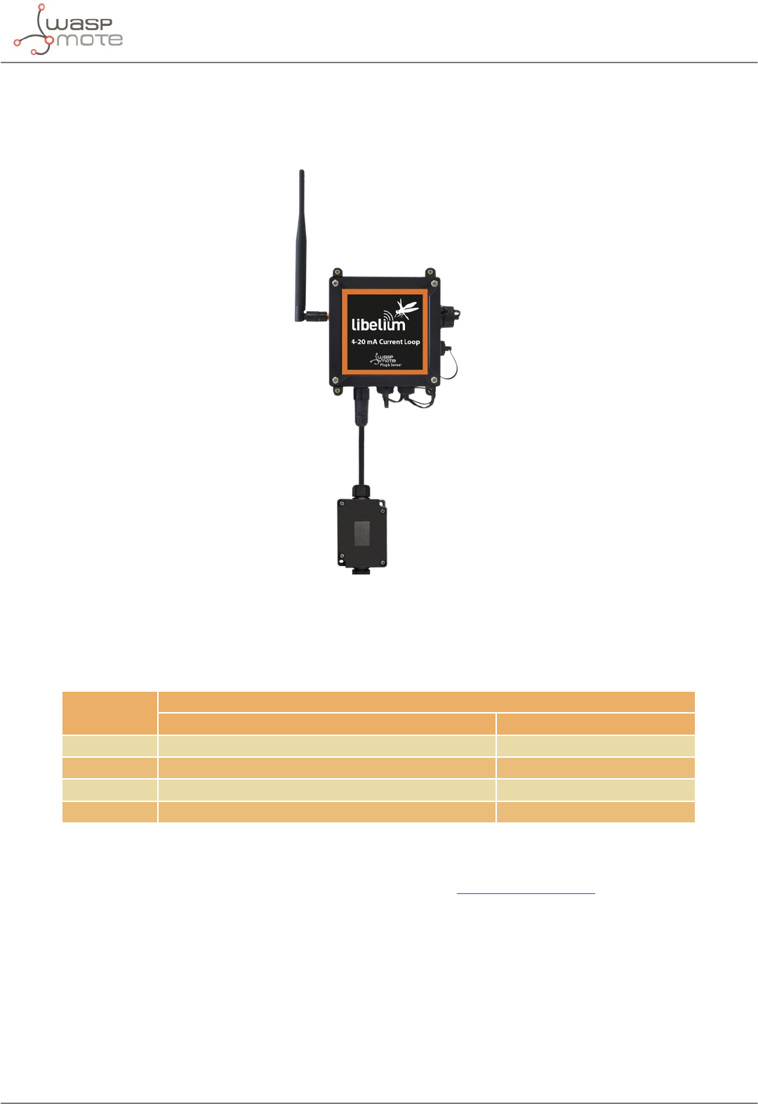
3.11.12. 4-20 mA Current Loop
The applications for this Plug & Sense! model are focused on adding wireless connectivity to 4-20 mA devices and
connecting them to the Cloud.
Figure: 4-20 mA Current Loop Waspmote Plug & Sense! model
Sensor sockets are congured as shown in the gure below.
Sensor
Socket
Sensor probes allowed for each sensor socket
Board channel Reference
A Channel 1 (type 2 and type 3) 9270-P, DB9-P
B Channel 2 (type 2 and type 3) 9270-P, DB9-P
C Channel 3 (type 2 and type 3) 9270-P, DB9-P
D Channel 4 (type 4) 9270-P, DB9-P
Figure: Sensor sockets configuration for 4-20 mA Current Loop model
Note: For more technical information about each sensor probe go to the Development section on the Libelium website.
-56- v8.2
Hardware
4. Hardware
4.1. Modular architecture
Waspmote is based on a modular architecture. The idea is to integrate only the modules needed in each device.
These modules can be changed and expanded according to needs.
The modules available for integration in Waspmote are categorized in:
•ZigBee/802.15.4 XBee modules (2.4 GHz, 868 MHz, 900 MHz)
•LoRaWAN module (433/868/900 MHz)
•LoRa module (868/900 MHz)
•Sigfox module (868/900 MHz)
•GPRS module (Quadband: 850/900/1800/1900 MHz)
•3G module (Dual-Band WCDMA/UMTS 900/2100 MHz and Tri-Band GSM/GPRS/EDGE 850/900/1800 MHz)
•NB-IoT / Cat-M module (global version, multiband)
•4G Module (Europe/Brazil, America and Australia versions)
•WiFi module
•Bluetooth modules: Bluetooth Low Energy and Bluetooth Pro
•NFC/RFID module
•GPS module
•Sensor modules (Sensor boards)
•Storage module: SD Memory Card
4.2. Specications
•Microcontroller: ATmega1281
•Frequency: 14.7456 MHz
•SRAM: 8 kB
•EEPROM: 4 kB
•FLASH: 128 kB
•SD Card: 16 GB
•Weight: 20 g
•Dimensions: 73.5 x 51 x 13 mm
•Temperature range: [-30 ºC, +70 ºC]*
* Temporary extreme temperatures are supported. Regular recommended usage: -20, +60 ºC.
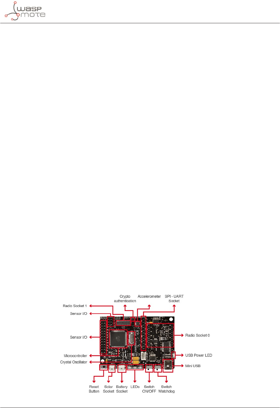
Figure: Main Waspmote components – Top side
-57- v8.2
Hardware
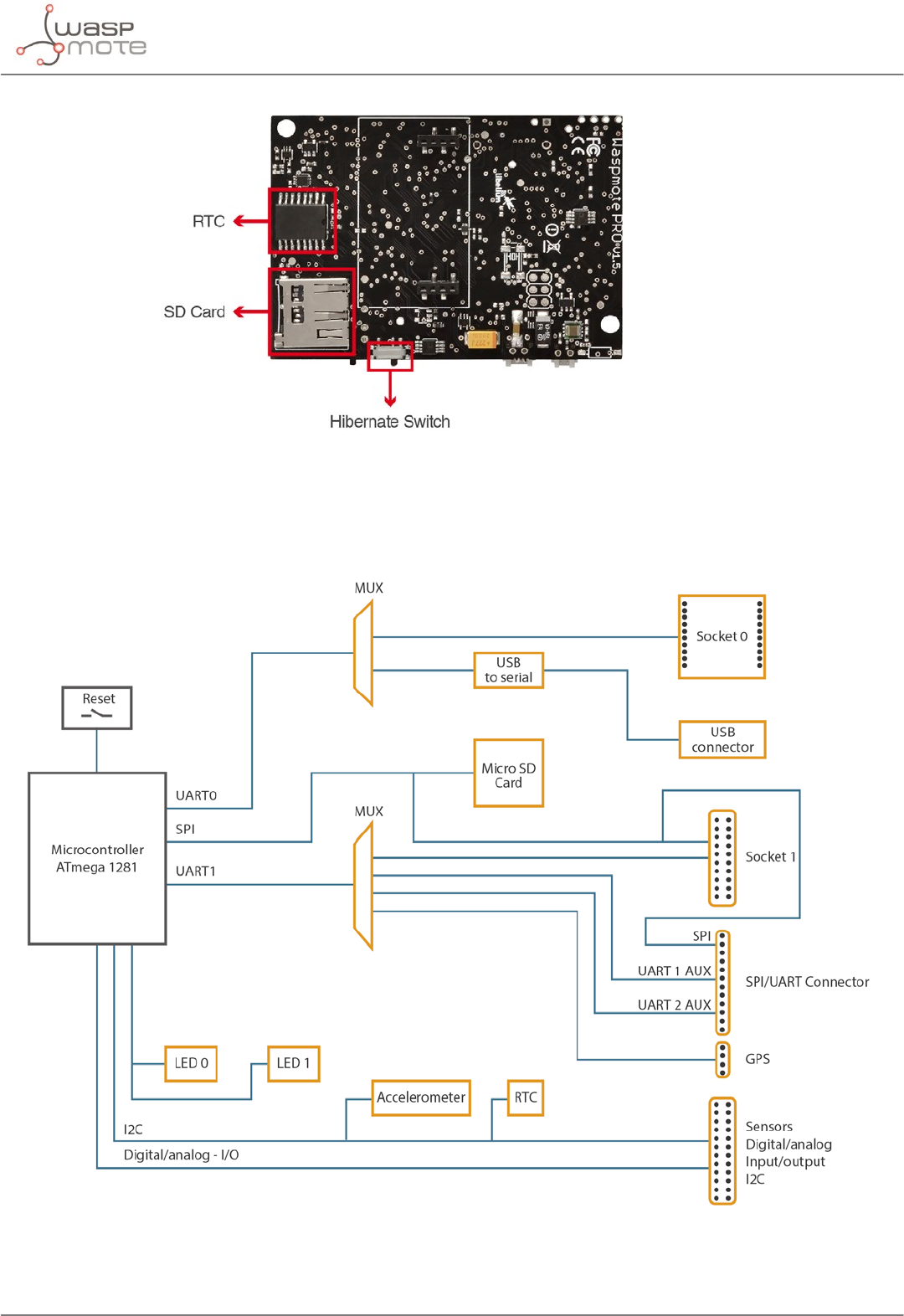
Main Waspmote components – Bottom side
4.3. Block diagram
Data signals:
Figure: Waspmote block diagrams – Data signals
-58- v8.2
Hardware
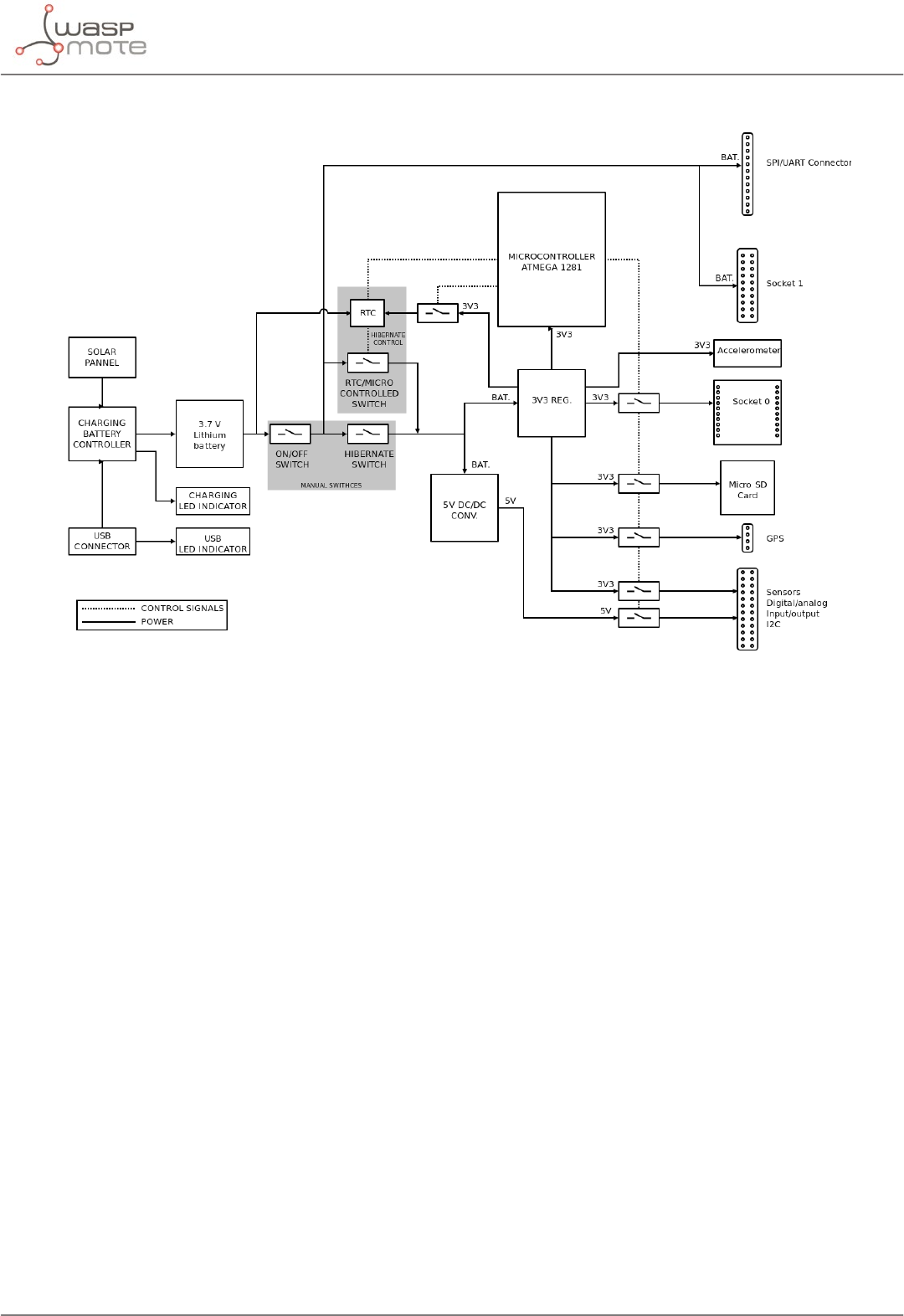
Power signals:
Figure: Waspmote block diagrams – Power signals
4.4. Electrical data
Operational values:
•Minimum operational battery voltage 3.3 V
•Maximum operational battery voltage 4.2 V
•USB charging voltage 5 V
•Solar panel charging voltage 6 - 12 V
•Battery charging current from USB 480 mA (max current input), 100 mA in batches since
summer 2018
•Battery charging current from solar panel 300 mA (max current input)
Absolute maximum values:
•Voltage in any pin [-0.5 V, +3.8 V]
•Maximum current from any digital I/O pin 40 mA
•USB power voltage 7 V
•Solar panel power voltage 18 V
•Charged battery voltage 4.2 V
-59- v8.2
Hardware
4.5. I/O
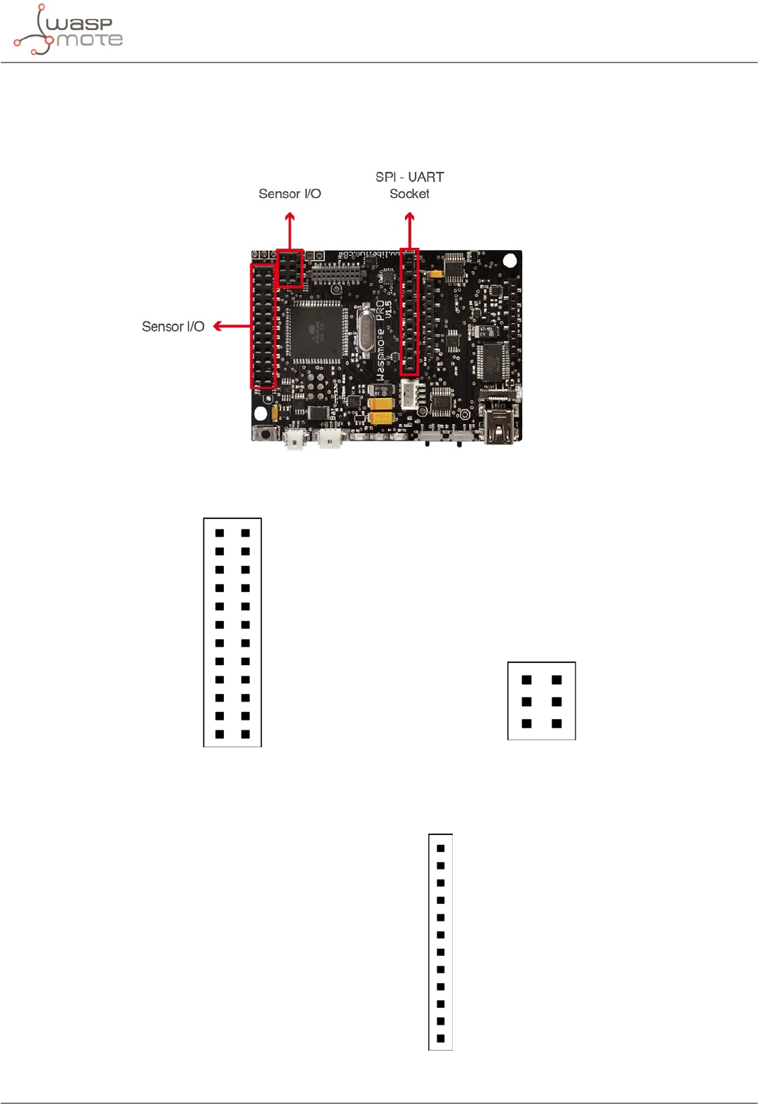
Waspmote can communicate with other external devices through the using dierent input/output ports.
Figure: I/O connectors in Waspmote
Sensor connector:
ANALOG
DIGITAL 8
DIGITAL 6
DIGITAL 4
DIGITAL 2
RESERVED
ANALOG 6
ANALOG 4
ANALOG 2
3V3 SENSOR POWER
GPS POWER
SDA
3V3 SENSOR POWER
GND
DIGITAL 7
DIGITAL 5
DIGITAL 3
DIGITAL 1
ANALOG 7
ANALOG 5
ANALOG 3
ANALOG 1
5V SENSOR POWER
SCL
GND
ANALOG 6
3V3 SENSOR
GND
ANALOG 7
3V3 SENSOR
Figure: Description of sensor connector pins
Auxiliary SPI-UART connector:
AUX SERIAL 1TX
AUX SERIAL 1RX
AUX SERIAL 2RX
AUX SERIAL 2TX
BATTERY
GND
SCK
RXD1
TXD1
3V3 SENSOR POWER
MOSI
MISO
Figure: Description of auxiliary SPI-UART connector pins

-60- v8.2
Hardware
4.5.1. Analog pins
Waspmote has 7 accessible analog inputs in the sensor connector. Each input is directly connected to the
microcontroller. The microcontroller uses a 10-bit successive approximation analog to digital converter (ADC).
The reference voltage value for the inputs is 0 V (GND). The maximum value of input voltage is 3.3 V which
corresponds with the microcontroller’s general power voltage.
To obtain input values, the function analogRead(analog input) is used, the function’s input parameter will be the
name of the input to be read “ANALOG1, ANALOG2…” (see sensor connector gure). The value obtained from this
function will be an integer number between 0 and 1023, 0 corresponds to 0 V and 1023 to 3.3 V.
The analog input pins can also be used as digital input/output pins. If these pins are going to be used as digital
ones, the following correspondence list for pin names must be taken into account:
Analog pin Digital pin
ANALOG1 => 14
ANALOG2 => 15
ANALOG3 => 16
ANALOG4 => 17
ANALOG5 => 18
ANALOG6 => 19
ANALOG7 => 20
{
val = analogRead(ANALOG1);
}
4.5.2. Digital pins
Waspmote has digital pins which can be congured as input or output depending on the needs of the application.
The voltage values corresponding to the dierent digital values would be:
•LOW: 0 V for logic 0
•HIGH: 3.3 V for logic 1
The instructions for control of digital pins are:
{
// set DIGITAL3 pin as input and read its value
pinMode(DIGITAL3, INPUT);
val = digitalRead(DIGITAL3);
// set DIGITAL3 pin as output and set it LOW
pinMode(DIGITAL3 ,OUTPUT);
digitalWrite(DIGITAL3, LOW);
}
4.5.3. PWM
DIGITAL1 pin can also be used as output PWM (Pulse Width Modulation) with which an analog signal can be
“simulated”. It is actually a square wave between 0 V and 3.3 V for which the proportion of time when the signal
is high can be changed (its working cycle) from 0% to 100%, simulating a voltage of 0 V (0%) to 3.3 V (100%).The
resolution is 8 bit, so up to 255 values between 0-100% can be congured. The instruction to control the PWM
output is analogWrite(DIGITAL1, value); where value is the analog value (0-255).
{
analogWrite(DIGITAL1, 127);
}

-61- v8.2
Hardware
4.5.4. UART
There are 2 UARTs in Waspmote: UART0 and UART1. Besides, there are several ports which might be connected
to these UARTs through 2 dierent multiplexers, one for each UART.
•UART0 is shared by the USB port and the Socket0. This socket is used for XBee modules, LoRaWAN module,
LoRa module, Sigfox module, RFID/NFC module, Bluetooth modules, WiFi module, RS-485 module, etc. The
multiplexer in this UART controls the data signal which by default is always switched to Socket0. When the
USB needs to send info through the UART0, the multiplexer is momentarily switched to the USB port and
set back again to Socket0 after printing.
•UART1 is shared by 4 ports: Socket1, GPS socket, Auxiliar1 and Auxiliar2 sockets. It is possible to select in
the same program which of the 4 ports is connected to UART1 in the microcontroller. UART1 multiplexer
conguration is carried out using the following instructions:
{
Utils.setMuxAux1(); // set Auxiliar1 socket
Utils.setMuxAux2(); // set Auxiliar2 socket
Utils.setMuxGPS(); // set GPS socket
Utils.setMuxSocket1(); // set Socket1
}
4.5.5. I2C
The I2C communication bus is also used in Waspmote where several devices are connected in parallel: the
accelerometer, a crypto-authentication memory and the RTC. In all cases, the microcontroller acts as master while
the other devices connected to the bus are slaves.
4.5.6. SPI
The SPI port on the microcontroller is used for communication with the micro SD card. All operations using the bus
are performed clearly by the specic library. The SPI port is also available in the SPI/UART connector and Socket0.
4.5.7. USB
USB is used in Waspmote for communication with a computer or compatible USB devices. This communication
allows the microcontroller’s program to be loaded.
For USB communication, microcontroller’s UART0 is used. The FT232RL chip carries out the conversion to USB
standard.
4.6. Real Time Clock - RTC
Waspmote has a built in Real Time Clock – RTC, which keeps it informed of the time. This allows Waspmote to be
programmed to perform time-related actions such as:
“Sleep for 1h 20 min and 15sec, then wake up and perform the following action..”
Or even programs to perform actions at absolute intervals, e.g.:
“Wake on the 5th of next month at 00:20 and perform the following action..”
All RTC programming and control is done through the I2C bus.
Alarms:
Alarms can be programmed in the RTC specifying day/hour/minute/second. That allows total control about when
the mote wakes up to capture sensor values and perform actions programmed on it. This allows Waspmote to
be in the saving energy modes (Deep Sleep and Hibernate) and makes it wake up just at the required moment.

-62- v8.2
Hardware
As well as relative alarms, periodic alarms can be programmed by giving a time measurement, so that Waspmote
reprograms its alarm automatically each time one event is triggered.
The RTC chosen is the Maxim DS1337C, which operates at a frequency of 32.768 kHz (a second divisor value which
allows it to quantify and calculate time variations with high precision).
The RTC is powered by the battery. When the battery is connected, the RTC is powered on. However, the user must
keep in mind that if the battery is removed or out of load, then time data will be not maintained. This is the reason
we suggest to use RTC time as ‘relative’ and not ‘absolute’ (see Programming Guide for more info).
A coin or button battery is not needed. They have a limited life and therefore Waspmote can have a much longer
power life expectancy. This is so because the RTC is powered from the “main” battery which has a much bigger
charge.
The RTC is responsible for waking Waspmote up from sleep modes like Deep Sleep and Hibernate. This makes
possible to use its battery to just power the RTC in sleep modes. The RTC controls when the device has to wake
up and perform a particular action. This permits a consumption of 7 uA in the Hibernate mode. Please refer to
“Energy System” section for more information.
Related API libraries: WaspRTC.h, WaspRTC.cpp
All information about their programming and operation can be found in the RTC Programming Guide.
All the documentation is located in the Development section in the Libelium website.
-63- v8.2
Hardware
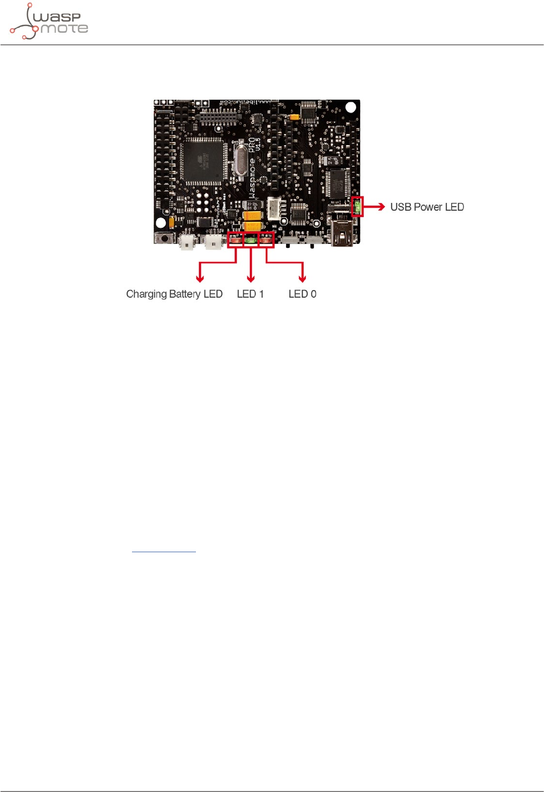
4.7. LEDs
Figure: Visual indicator LEDs
The Waspmote LEDs are:
•Charging battery LED indicator: A red LED indicating that there is a battery connected in Waspmote which
is being charged. The charging can be done through a mini-USB cable or through a solar panel connected to
Waspmote. Once the battery is completely charged, the LED switches o automatically.
•LED0 (programmable LED): A green LED is connected to the microcontroller. It is totally programmable by
the user from the program code. In addition, the LED0 indicates when Waspmote resets, blinking each time
a reset on the board is carried out.
•LED1 (programmable LED): A red LED is connected to the microcontroller. It is totally programmable by
the user from the program code.
•USB Power LED indicator: A green LED which indicates when Waspmote is connected to a compatible USB
port either for battery charging or programming. When the LED is on, it indicates that the USB cable is con-
nected correctly. When the USB cable is removed, this LED will switch o automatically.
Please refer to Waspmote Utilities guide for more information.
-64- v8.2
Architecture and system
5. Architecture and system
5.1. Concepts
The Waspmote’s architecture is based on the Atmel ATmega1281 microcontroller.
When Waspmote is connected and starts the bootloader, there is a waiting time (62.5 ms) before beginning the
rst instruction, this time is used to start loading new compiled programs updates. If a new program is received
from the USB during this time, it will be loaded into the FLASH memory (128 kB) substituting already existing
programs. Otherwise, if a new program is not received, the last program stored in the memory will start running.
The structure of the codes is divided into 2 basic parts: setup and loop. Both parts of the code have sequential
behaviour, executing instructions in the set order.
The setup is the rst part of the code, which is only run once when the code is initialized. In this part it is
recommended to include the initialization of the modules which are going to be used, as well as the part of the
code which is only important when Waspmote is started.
The part named loop runs continuously, forming an innite loop. Because of the behavior of this part of the code,
the use of interruptions is recommended to perform actions with Waspmote.
A common programming technique to save energy would be based on blocking the program (either keeping the
micro awake or asleep in particular cases) until any of the interruptions available in Waspmote show that an event
has occurred. This way, when an interruption is detected the associated function, which was previously stored in
an interruption vector, is executed.
To be able to detect the capture of interruptions during the execution of the code, a series of ags have been created
and will be activated to indicate the event which has generated the interruption (see chapters “Interruptions” and
“Energy system”).
Figure: Blocking loop, interruption appears and is dealt with
When Waspmote is reset or switched on, the code starts again from the setup function and then the loop function.
By default, variable values declared in the code and modied in execution will be lost when a reset occurs or there
is no battery. To store values permanently, it is necessary to use the microcontroller’s EEPROM (4 kB) non-volatile
memory. EEPROM addresses from 0 to 1023 are used by Waspmote to save important data, so they must not be
over-written. Thus, the available storage addresses go from 1024 to 4095. Another option is to make use of the
SD card.

-65- v8.2
Architecture and system
5.2. Timers
Waspmote uses a quartz oscillator which works at a frequency of 14.7456 MHz as a system clock. In this way, every
125ns the microcontroller runs a low level (machine language) instruction. It must be taken into account that each
line of C++ code of a program compiled by Waspmote includes several instructions in machine language.
Waspmote is a device prepared for operation in adverse conditions with regards to noise and electromagnetic
contamination, for this reason, to ensure stable communication at all times with the dierent modules connected
through a serial line to the UARTs (communication modules and USB) a maximum transmission speed of 115200
bps has been set for the communication modules and the USB port, and 4800 for the GPS, so that the success
rate in received bits is 100%.
5.2.1. Watchdog
The ATmega1281 microcontroller has an internal Enhanced Watchdog Time – WDT. The WDT precisely counts
the clock cycles generated by a 128 kHz oscillator. The WDT generates an interruption signal when the counter
reaches the set value. This interruption signal can be used to wake the microcontroller from the Sleep mode or
to generate an internal alarm when it is running in on mode, which is very useful when developing programs with
timed interruptions.
The WDT allows the microcontroller to wake up from a low consumption Sleep mode by generating an interruption.
For this reason, this clock is used as a time-based alarm associated with the microcontroller’s Sleep mode. This
allows very precise control of small time intervals: 16 ms, 32 ms, 64 ms, 128 ms, 256 ms, 500 ms, 1 s, 2 s, 4 s, 8
s. For intervals over 8 s (Deep Sleep mode), the RTC is used and not the microcontroller.
More information about the interruptions generated by the Watchdog can be found in the “Energy system” chapter.
Related API libraries: WaspPWR.h, WaspPWR.cpp
All information about their programming and operation can be found in the Interrupt Programming Guide.
All the documentation is located in the Development section in the Libelium website.
5.2.2. RTC Watchdog for reseting Waspmote
One of the alarms of the RTC (Alarm 2) is connected to a Watchdog reset circuit that is able to reset the microcontroller
of Waspmote when the alarm is generated. This Watchdog has been implemented for reseting Waspmote if it gets
stuck. That periodical reset avoids erratic behaviour. This is highly recommended for applications that need to be
very robust and can never stop working. The use of the Watchdog feature enssures us that our Waspmote will
never stop working.
The Watchdog feature requires the physical watchdog switch to be put in “enable” position.
Figure: RTC Watchdog switch
Related API libraries: WaspRTC.h, WaspRTC.cpp
All information about the RTC programming and operation can be found in the RTC Programming Guide.
All the documentation is located in the Development section in the Libelium website.

-66- v8.2
Architecture and system
5.2.3. RTC
As shown in the “Hardware” chapter, Waspmote has a real time clock (RTC) running a 32.786 kHz which allows to
set an absolute time.
Alarms can be programmed in the RTC specifying day/hour/minute/second. This allows total control when the
mote wakes up to capture values and perform actions programmed on it. Also, the RTC allows Waspmote to
function in the maximum energy saving modes (Deep Sleep and Hibernate) and to wake up just at the required
moment.
The RTC allows the microcontroller to be woken from a low consumption state by generating an interruption. For
this reason, it has been associated to the microcontroller’s Deep Sleep and Hibernate modes, making it possible to
put the microcontroller to sleep, and wake it up by activating an alarm in the RTC. Sleeping intervals can go from
1 s to minutes, hours or even days.
More information about the interruptions generated by the RTC and Deep Sleep and Hibernate modes can be
found in the “Energy system” chapter.
Related API libraries: WaspRTC.h, WaspRTC.cpp
All information about the RTC programming and operation can be found in the RTC Programming Guide.
All the documentation is located in the Development section in the Libelium website.
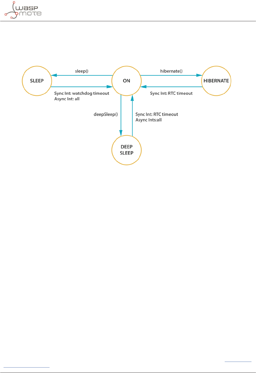
-67- v8.2
Interruptions
6. Interruptions
Interruptions are signals received by the microcontroller which indicate it must stop the task it is doing to handle
an event that has just happened. Interruption control frees the microcontroller from having to control sensors all
the time. It also makes the sensors warn Waspmote when a determined value (threshold) is reached.
Figure: Diagram of mode in Waspmote
Waspmote is designed to work with 2 types of interruptions: Synchronous and asynchronous:
•Synchronous interruptions: They are scheduled by timers. They allow to program when we want them to
be triggered. There are 2 types of timer alarms: periodic and relative.
-Periodic alarms are those to which we specify a particular moment in the future, for example: “Alarm
programmed for every 4th day of the month at 00:01 and 11 seconds”. They are controlled by the RTC.
-Relative alarms are programmed taking into account the current moment, eg: “Alarm programmed
for 5 minutes and 10 seconds”. They are controlled through the RTC and the microcontroller’s internal
Watchdog.
•Asynchronous Interruptions: These are not scheduled, so it is not known when they will be triggered.
Types:
-Sensors: The sensor boards can be programmed so that an alarm is triggered when a sensor reaches a
certain threshold.
-Accelerometer: Waspmote’s accelerometer can be programmed so that certain events such (as a fall or
change of direction) generate an interruption.
All interruptions, both synchronous and asynchronous can wake Waspmote up from the Sleep and the Deep
Sleep modes. However, only the synchronous interruption by the RTC is able to wake it up from the Hibernate
mode.
The Hibernate mode totally disconnects the Waspmote power, leaving only the battery powering the RTC to
wake Waspmote up when the time alarm is reached. Because of this disconnection, when the RTC generates the
corresponding alarm, the power in Waspmote is reconnected and the code starts again from the setup.
The way of detecting whether a reboot from the Hibernate mode has happened is to check whether the
corresponding ag has been activated. The activation of this ag happens when the ifHibernate() function is
called, which must be done at the beginning of the setup part of the code. This way, when Waspmote starts, it
tests if it is a normal start or if it is a start from the Hibernate mode.
All information about the programming and operation of interruptions can be found in the Interruption
Programming Guide.

-68- v8.2
Energy system
7. Energy system
7.1. Concepts
Waspmote has 4 operational modes:
•On: Normal operation mode. Consumption in this state is 17 mA.
•Sleep: The main program is paused, the microcontroller passes to a latent state, from which it can be woken
up by all asynchronous interruptions and by the synchronous interruption generated by the Watchdog. The
duration interval of this state is from 32 ms to 8 s. Consumption in this state is 30 μA.
•Deep Sleep: The main program pauses, the microcontroller passes to a latent state from which it can be
woken up by all asynchronous interruptions and by the synchronous interruption triggered by the RTC. The
interval of this cycle can be from seconds to minutes, hours, days. Consumption in this state is 33 μA.
•Hibernate: The main program stops, the microcontroller and all the Waspmote modules are completely
disconnected. The only way to reactivate the device is through the previously programmed alarm in the RTC
(synchronous interrupt). The interval of this cycle can be from seconds to minutes, hours, days. Almost all
devices are totally disconnected from the battery: only the RTC is powered through the battery, from which
it consumes 7 μA.
Consumption Microcontroller Cycle Accepted interruptions
On 17 mA On - All interruption sources
Sleep 30 μA On Depends on INT
source
All interruption sources
Deep Sleep 33 μA On 1 s – 31 days All interruption sources (RTC always
used)
Hibernate 7 μA O 1 s – 31 days Only RTC
On the other hand, each module (radio, sensor board, etc) might have up to several operation modes.
•On: Normal operation mode.
•Sleep: Some communication modules permit to set up sleep modes so as to save energy (depends on each
module).
•O: By using Waspmote’s digital switches (controlled by the microcontroller), the module is switched o
completely. This mode has been implemented by Libelium as an independent layer of energy control,
so that it can reduce consumption to a minimum (~7 μA) without relegating to techniques implemented by
the manufacturer.
For complete information about interruption types and their handling, see the “Interruption” chapter.
Related API libraries: WaspPWR.h, WaspPWR.cpp
All information about the programming and operation of interruptions can be found in the Interrupt Programming
Guide.
All the documentation is located in the Development section in the Libelium website.
Note: Before setting Waspmote to a low-power consumption mode, it is always recommended to switch any communication
module o.
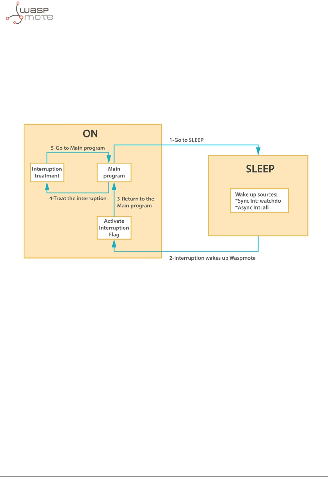
-69- v8.2
Energy system
7.2. Sleep mode
In this mode, the main program is paused, the microcontroller passes to a latent state, from which it can be woken
by all asynchronous interruptions and by the synchronous interruption generated by the Watchdog. When the
Watchdog Timer is set up, the duration interval can be programmed from 16 ms to 8 s. Consumption in this state
is 30 μA.
In this mode the microcontroller stops executing the main program. The program stack where all the variables and
log values are stored keep their value, so when Waspmote returns to on mode, the next instruction is executed
and the variable values are maintained.
Figure: From on to Sleep mode
The following example would set Waspmote in the Sleep mode for 32 ms. The microcontroller would be in a state
of minimum consumption waiting for the synchronous interruption from the Watchdog:
{
PWR.sleep(WTD_32MS, ALL_OFF);
}
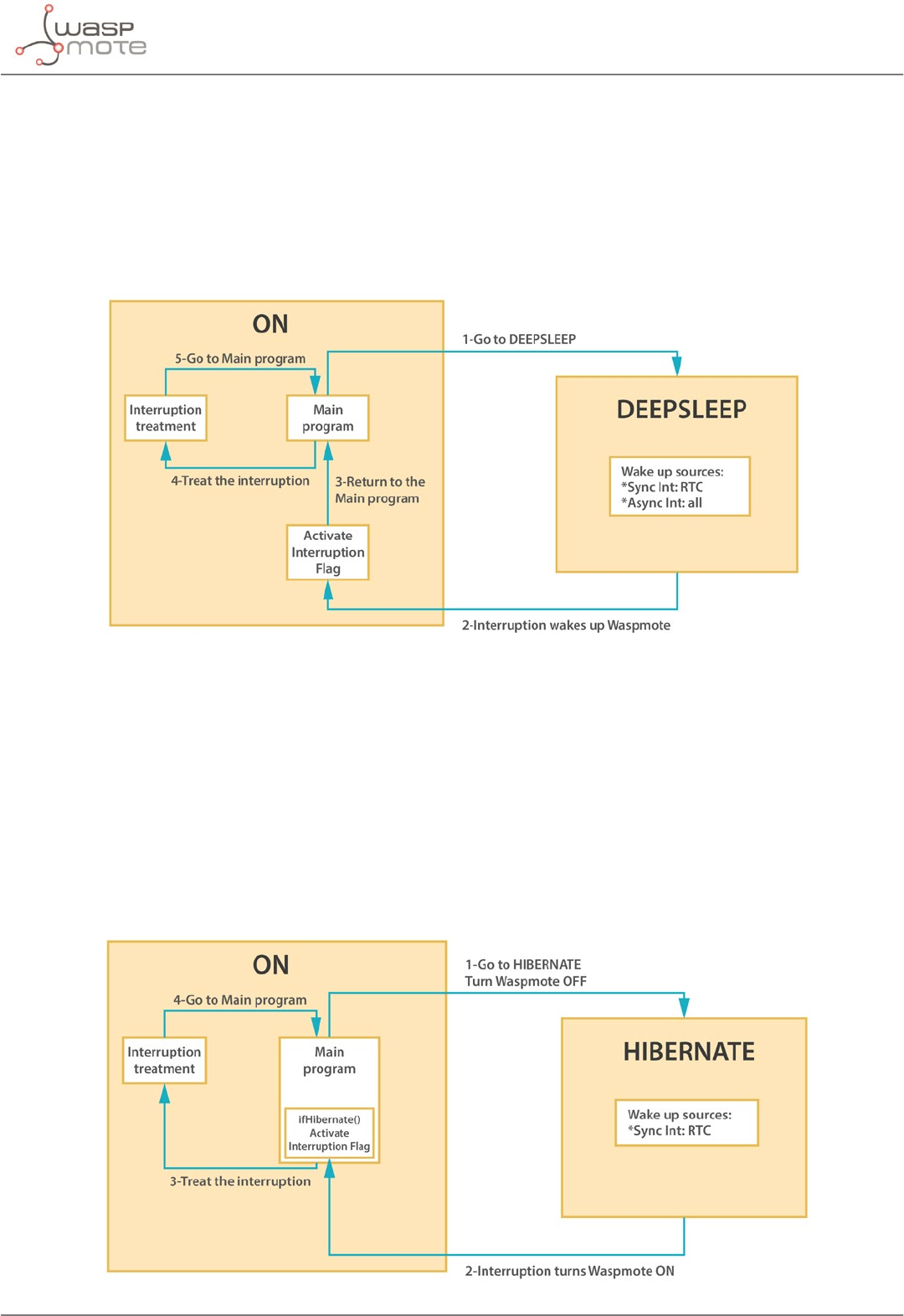
-70- v8.2
Energy system
7.3. Deep Sleep mode
In this mode, the main program is paused, the microcontroller passes to a latent state from which it can be woken
by all the asynchronous interruptions and by the synchronous interruption launched by the RTC. The interval of
this cycle can go from seconds to minutes, hours, days. Consumption in this state is 33 μA.
In this mode the microcontroller stops executing the main program. The program stack where all the variables and
log values are stored keep their value, so when Waspmote returns to on mode, the next instruction is executed
and the variable values are maintained.
Figure: From on to Deep Sleep mode
7.4. Hibernate mode
In this mode, the main program stops, the microcontroller and all the modules are completely disconnected.
The only way to reactivate the device is through the previously programmed alarm in the RTC (synchronous
interrupt). The interval for this cycle can go from seconds to minutes, hours or days. Almost all devices are
totally disconnected from the battery: only the RTC is powered through the battery, from which it consumes 7μA.
In this mode the microcontroller does not store any values from variables or from the program stack. When
leaving the Hibernate state the microcontroller is reset, so the setup and loop routines are run as if the main
switch were activated.
Figure: From on to Hibernate mode

-71- v8.2
Energy system
The Hibernate mode requires the physical Waspmote’s hibernate switch to be put in “enable” position. It is
necessary to follow the next steps when executing the program for the rst time after uploading it to Waspmote:
1. Connect the battery.
2. Switch Waspmote on.
3. Wait for the red LED to light on and turn the hibernate switch to the “enable” position while the red LED is on.
4. Once the hibernate switch is in the “enable” position, the green LED must blink to indicate that the program
is running.
The following example would set Waspmote in the Hibernate mode for 2 days, 1 hour and 30 minutes. The
microcontroller would be switched o waiting for the RTC to switch the device on again with a synchronous
interruption.
{
PWR.hibernate(“02:01:30:00”, RTC_OFFSET, RTC_ALM1_MODE2);
}
Related API libraries: WaspPWR.h, WaspPWR.cpp
All information about the programming and operation of sleep modes can be found in the Interruption Programming
Guide.
All the documentation is located in the Development section in the Libelium website.
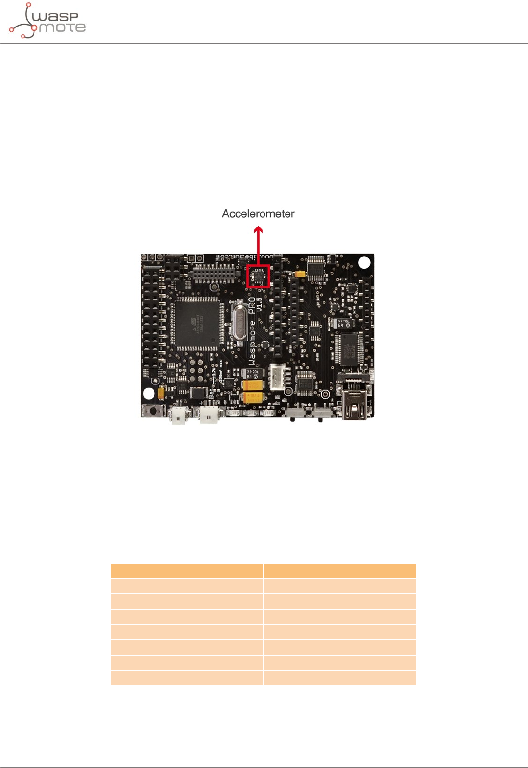
-72- v8.2
Sensors
8. Sensors
8.1. Accelerometer
Waspmote has a built-in acceleration sensor LIS3331LDH, by STMicroelectronics, which informs the mote of
acceleration variations experienced on each one of the 3 axes (X,Y, Z).
The integration of this sensor allows the measurement of acceleration on the 3 axes (X, Y, Z), establishing 4 kinds
of events: Free Fall, inertial wake up, 6D movement and 6D position which are explained in the Interruption
Programming Guide.
The LIS331DLH has dynamically user-selectable full scales of ±2g/±4g/±8g and it is capable of measuring
accelerations with output data rates from 0.5 Hz to 1 kHz.
The device features ultra low-power operational modes that allow advanced power saving and smart sleep to
wake-up functions.
The accelerometer has several power modes, the output data rate (ODR) will depend on the power mode selected.
The power modes and output data rates are shown in this table:
Power mode Output data rate (Hz)
Power down --
Normal mode 1000
Low-power 1 0.5
Low-power 2 1
Low-power 3 2
Low-power 4 5
Low-power 5 10
This accelerometer has an auto-test capability that allows the user to check the functioning of the sensor in the
nal application. Its operational temperature range is between -40 ºC and +85 ºC.
The accelerometer communicates with the microcontroller through the I2C interface. The pins that are used for
this task are the SCL pin and the SDA pin, as well as another interruption pin to generate the interruptions.
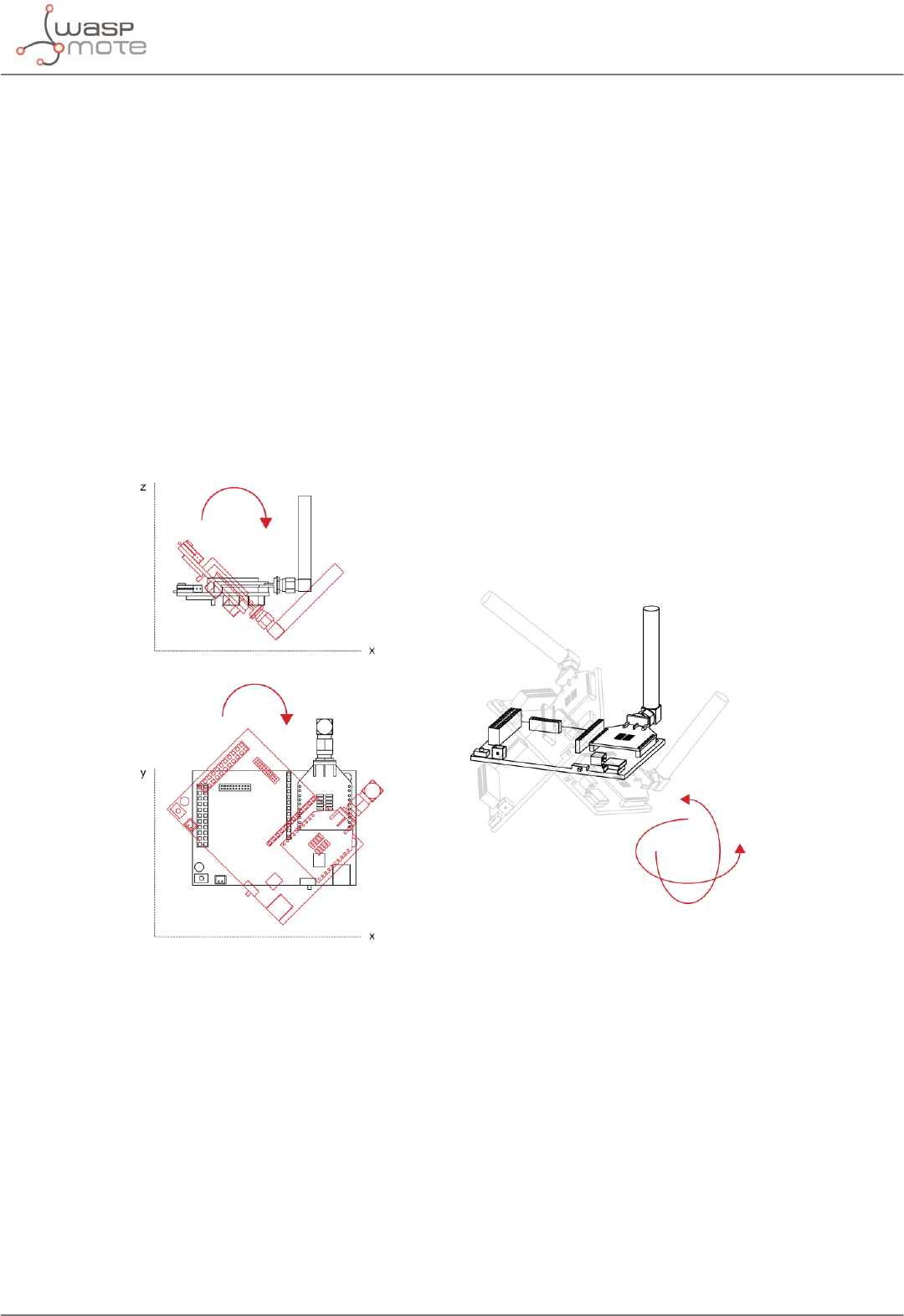
-73- v8.2
Sensors
The accelerometer has 4 types of event which can generate an interrupt: free fall, inertial wake up, 6D movement
and 6D position.
These thresholds and times are set in the WaspACC.h le.
To show the ease of programming, an extract of code about how to get the accelerometer values is included
below:
{
ACC.ON();
ACC.getX();
ACC.getY();
ACC.getZ();
}
Some gures with possible uses of the accelerometer are shown below:
Rotation and twist:
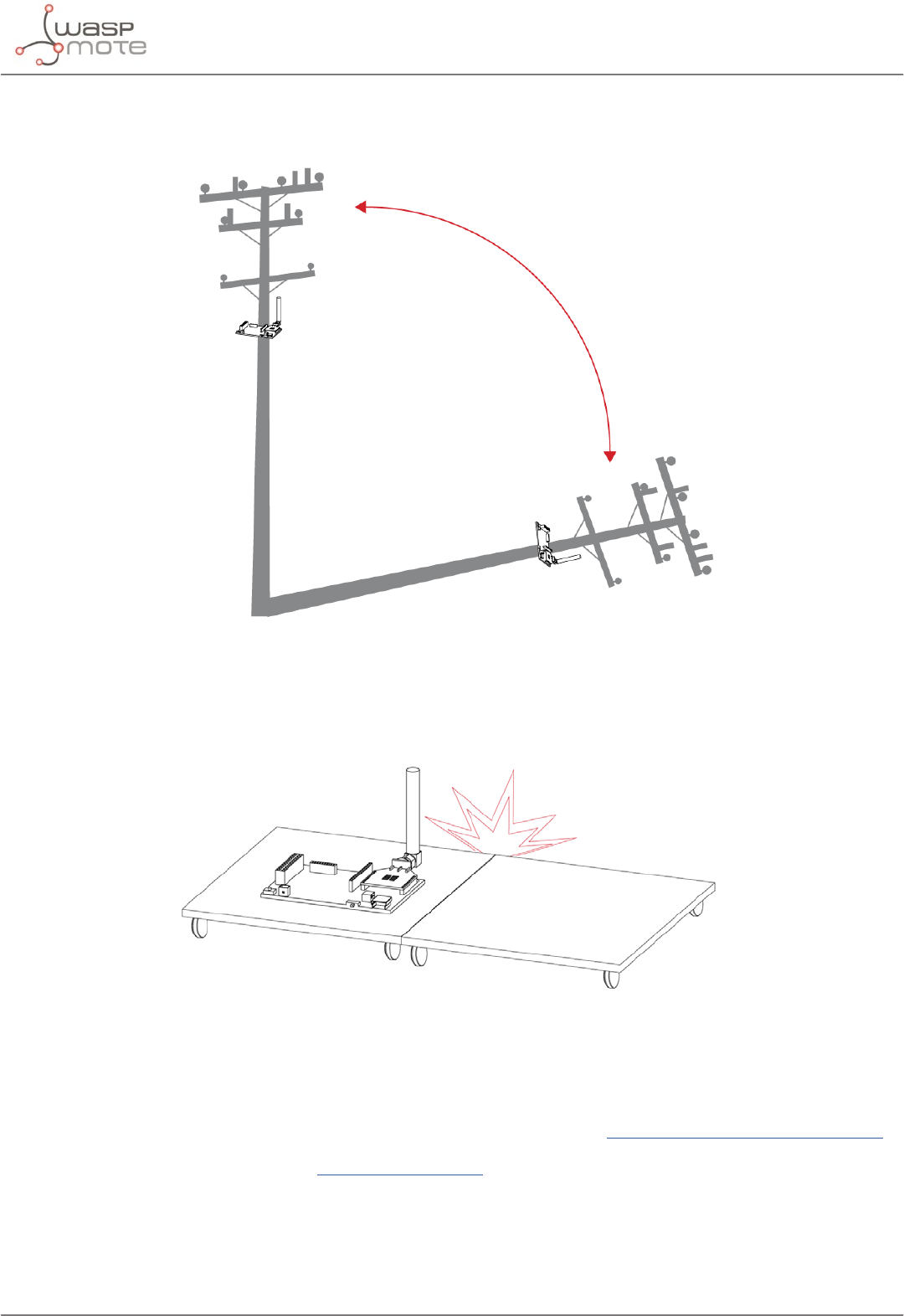
-74- v8.2
Sensors
Free fall of objects in which it is installed:
Crash:
More information about interruptions generated by the accelerometer can be found in the chapter “Interruptions”
and in the Interruption Programming Guide.
Related API libraries: WaspACC.h, WaspACC.cpp
All information about their programming and operation can be found in the Accelerometer Programming Guide.
All the documentation is located in the Development section in the Libelium website.

-75- v8.2
Sensors
8.2. Integration of new sensors
The Waspmote design is prepared for the integration of both input (sensors) and output (actuators) which allows
to grow the wide range of existing Waspmote sensor boards. The new sensors can be connected to Waspmote’s
2x12 and 1x12 pin connectors, which permit to use 16 input and output signals, 7 of which can be used as analog
inputs and 1 as a PWM (Pulse Width Modulation) output signal. Besides, there is a line to ground, 3.3 V and 5 V
power feeds, 2 selectable connections to the serial communication (UART) inputs and outputs, connection to the
2 lines of the (I2C) SCL and SDA Inter-Integrated Circuit bus, and connection to inputs for high level and low level
interrupt. An image of the Waspmote output connectors can be seen in the “I/O” section.
The management the 2 power lines (3.3 and 5 V) for the sensor boards (described in more depth in section
”Sensors” → Power) is carried out through 2 solid state switches which allow the continuous ow of a current of up
to 200 mA and whose control can be programmed using the functions included in the WaspPWR library, described
in the les WaspPWR.h and WaspPWR.cpp.
The input and output voltage values for both digital and analog pins will be between 0 V and 3.3 V, logic zero (‘0’)
being found in values less than 0.5 V and logic one (‘1’) in values higher than 2.30 V. To read analog signals, the
microcontroller has a 10-bit analog-to-digital converter which allows a resolution of 3 mV. Waspmote also has one
8-bit resolution PWM output pin for the generation of analog signals. Information on the libraries and instructions
used for reading and writing on these pins can be found in the API manual.
Waspmote includes 2 interruption pins, a low level (TXD1) one and a high level (RXD1) one, which oer an
alternative to reading the sensors by survey, allowing the microcontroller to be woken up when an event occurs
(such as exceeding a certain threshold in a comparator) which generates a change in a digital signal connected to
one of the above pins, facilitating the sensor reading only at the moments when a remarkable event occurs.
This option is especially recommended for low consumption sensors that may remain active for long periods of
time. Reading by survey (switched on and cyclical sensor reading after a set time) is more appropriate for those
that, in addition to showing greater consumption, do not require monitoring that generates an alarm signal.
The interruptions can be managed using the warning functions and vectors (ags) dened in the Winterruptions
library, le Winterruptions.c. More can be learnt about their use in the Interruption Programming Guide.
Sensors reading can generate 3 types of response: storage of collected data (on the SD card), wireless transmission
of data (via wireless module) or automatic activation through an actuator directly controlled by the microcontroller’s
output signals or through a switch or relay.
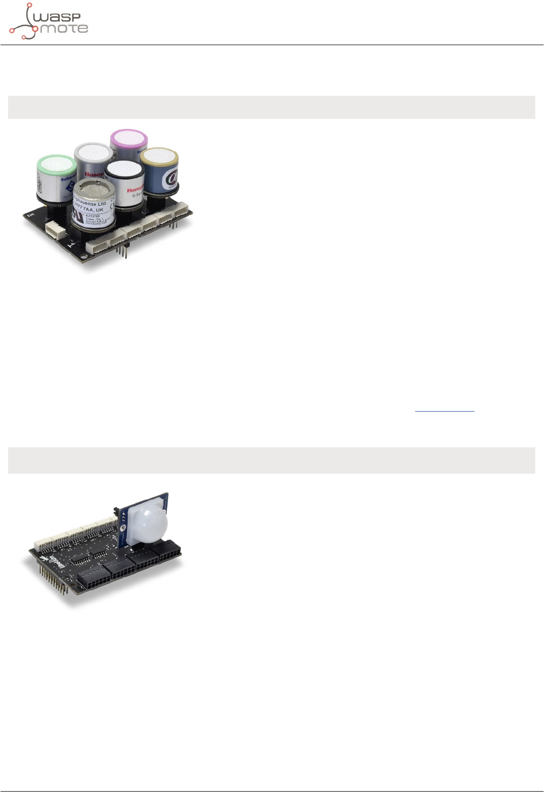
-76- v8.2
Sensors
8.3. Sensor Boards
GASES PRO v3* APPLICATIONS SENSORS
Figure: Gases PRO Board
(*) Calibrated gas sensors are manufactured
once the order has been placed to ensure
maximum durability of the calibration feature.
Manufacturing process and delivery may take
from 4 to 6 weeks. Lifetime of calibrated gas
sensors is 6 months working at its maximum
accuracy. We strongly encourage our
customers to buy extra gas sensor probes to
replace the originals after that time to ensure
maximum accuracy and performance.
• City pollution
CO, NO, NO2, O3, SO2, Particle
Matter - Dust
• Air Quality Index calculation
SO2, NO2, Particle Matter - Dust,
CO, O3, NH3
• Emissions from farms and
hatcheries
CH4, H2S, NH3
• Greenhouse management
CO2, CH4, Humidity
• Control of chemical and
industrial processes
H2, HCl, CH4, SO2, CO2
• Indoor air quality
CO2, CO, Particle Matter - Dust, O3
• Forest res
CO, CO2
• Carbon Monoxide – CO
• Carbon Dioxide – CO2
• Molecular Oxygen – O2
• Ozone – O3
• Nitric Oxide – NO
• Nitric Dioxide – NO2
• Sulfur Dioxide – SO2
• Ammonia – NH3
• Methane – CH4 – and other
combustible gases
• Molecular Hydrogen – H2
• Hydrogen Sulde – H2S
• Hydrogen Chloride – HCl
• Hydrogen Cyanide - HCN
• Phosphine – PH3
• Ethylene Oxide – ETO
• Chlorine – Cl2
• Particle Matter (PM1 / PM2.5
/ PM10) – Dust Sensor [only
for Plug & Sense!]
• Temperature, Humidity and
Pressure
EVENTS v3 APPLICATIONS SENSORS
Figure: Events Board
• Security
Hall eect (doors and windows),
person detection PIR
• Emergencies
Presence detection and water level
sensors, temperature
• Control of goods in logistics
• Pressure/Weight
• Hall Eect
• Temperature, Humidity and
Pressure
• Liquid Presence
• Liquid Level
• Liquid ow
• Luminosity (Luxes)
• Presence (PIR)
• Ultrasound (distance
measurement)
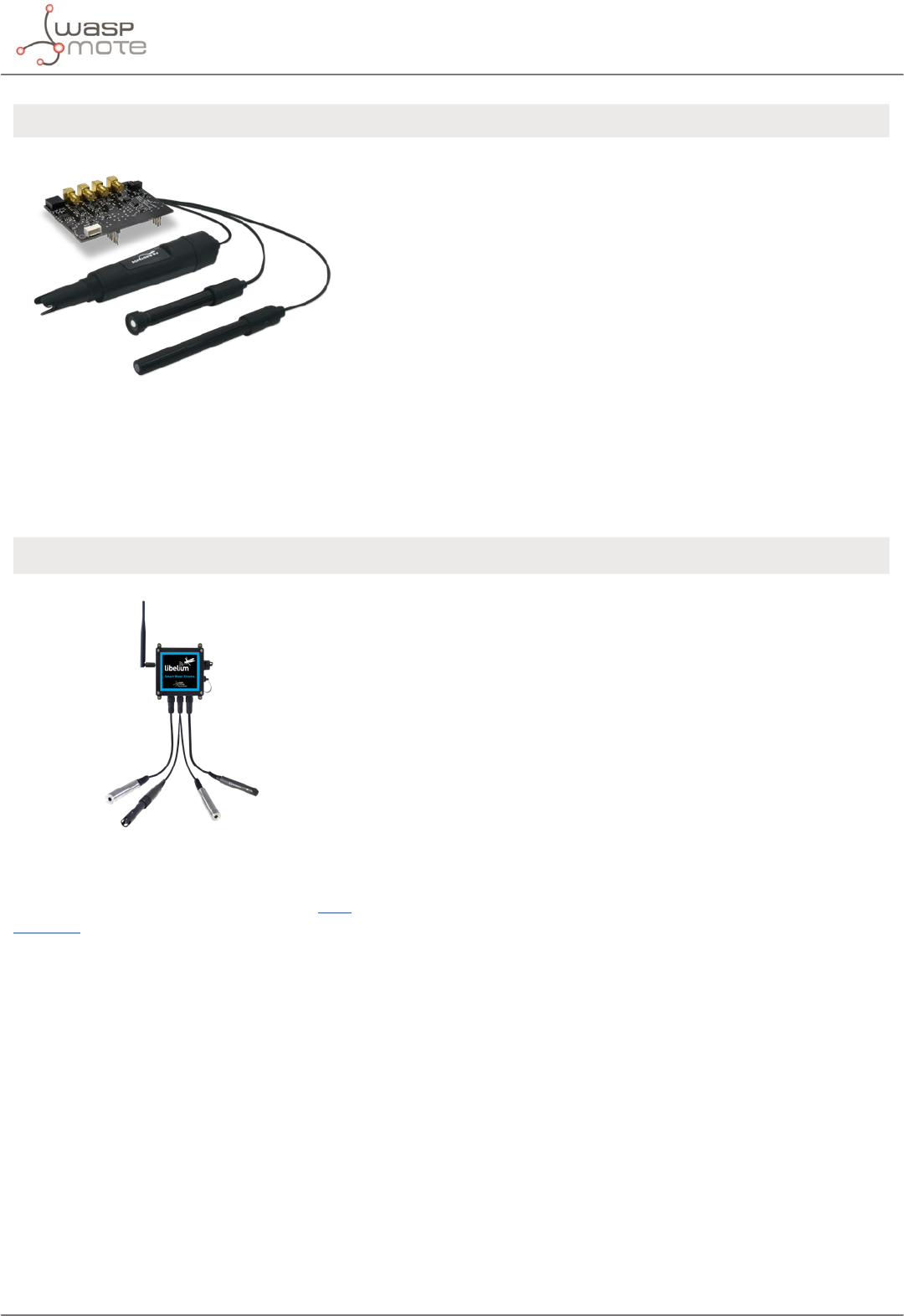
-77- v8.2
Sensors
SMART WATER v3 APPLICATIONS SENSORS
Figure: Smart Water Board
• Potable water monitoring
pH, ORP, Dissolved Oxygen (DO),
Nitrates, Phosphates
• Chemical leakage detection in
rivers
Extreme pH values signal chemical
spills, Dissolved Oxygen (DO)
• Swimming pool remote
measurement
pH, Oxidation-Reduction Potential
(ORP)
• Pollution levels in the sea
Temperature, Conductivity
(Salinity), pH, Dissolved Oxygen
(DO) and Nitrates
• pH
• Oxidation-Reduction
Potential (ORP)
• Dissolved Oxygen (DO)
• Conductivity
• Temperature
• Turbidity
SMART WATER XTREME APPLICATIONS SENSORS
Figure: Plug & Sense! Smart Water Xtreme
This sensor board is only available for Plug
& Sense!
•Industrial and public sewage
treatment plants
•Wastewater management
(nitrication and de-
nitrication)
•Surface water monitoring
•Fish farming, aquaculture
•Drinking water monitoring
•Process engineering plants
• Optical dissolved oxygen and
temperature OPTOD
• Titanium optical dissolved
oxygen and temperature
OPTOD
• pH, ORP and temperature
PHEHT
• Conductivity, salinity and
temperature C4E
• Inductive conductivity, salinity
and temperature CTZN
• Turbidity and temperature
NTU
• Suspended solid, turbidity,
sludge blanket and
temperature MES5
• Manta+ 40 sensor
• Chlorophyll sensor for Manta
probe
• BGA sensor for Manta probe
• Organic matter sensor CDOM/
FDOM for Manta probe
• Ammonium sensor for Manta
probe
• Nitrate sensor for Manta probe
• Chloride sensor for Manta
probe
• Sodium sensor for Manta
probe
• Calcium sensor for Manta
probe
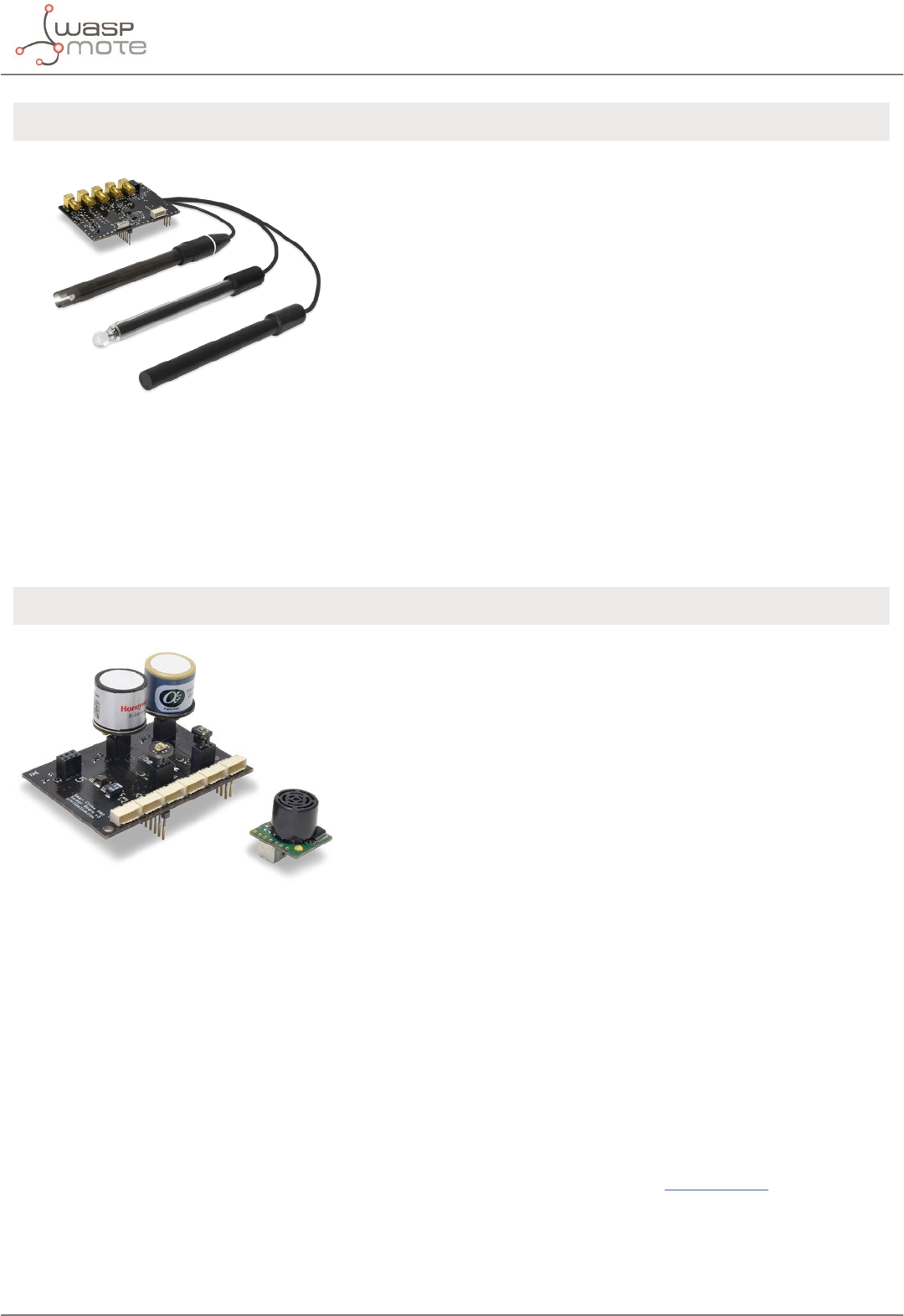
-78- v8.2
Sensors
SMART WATER IONS APPLICATIONS SENSOR
Figure: Smart Water Ions Board
• Drinking water quality control
Calcium (Ca2+), Iodide (I-), Chloride
(Cl-), Nitrate (NO3
-), Magnesium
(Mg2+), Sodium (Na+), pH
• Agriculture water monitoring
Calcium (Ca2+), Nitrate (NO3
-),
Magnesium (Mg2+), Sodium (Na+),
Potassium (K+), Ammonium (NH4
+),
pH
• Swimming pools
Bromide (Br-), Chloride (Cl-),
Fluoride (F-), pH
• Waste water treatment
Cupric (Cu2+), Silver (Ag+),
Fluoroborate (BF4
-), Lithium (Li+),
Nitrite (NO2
-), Perchlorate (ClO4
-),
pH
• Ammonium (NH4
+)
• Bromide (Br-)
• Calcium (Ca2+)
• Chloride (Cl-)
• Cupric (Cu2+)
• Fluoride (F-)
• Iodide (I-)
• Fluoroborate (BF4
-)
• Lithium (Li+)
• Nitrate (NO3
-)
• Nitrite (NO2
-)
• Magnesium (Mg2+)
• Perchlorate (ClO4
-)
• Potassium (K+)
• Silver (Ag+)
• Sodium (Na+)
• pH
• Temperature
SMART CITIES PRO* APPLICATIONS SENSORS
Figure: Smart Cities PRO Board
(*) Calibrated gas sensors are manufactured
once the order has been placed to ensure
maximum durability of the calibration
feature. Manufacturing process and delivery
may take from 4 to 6 weeks. Lifetime of
calibrated gas sensors is 6 months working
at its maximum accuracy. We strongly
encourage our customers to buy extra gas
sensor probes to replace the originals after
that time to ensure maximum accuracy and
performance.
• Noise maps
Monitor in real time the acoustic
levels in the streets of a city
• Air quality
Detect the level of gases and
particulates in the air
• Waste management
Measure the garbage levels
in bins to optimize the trash
collection routes
• Carbon Monoxide – CO
• Carbon Dioxide – CO2
• Molecular Oxygen – O2
• Ozone – O3
• Nitric Oxide – NO
• Nitric Dioxide – NO2
• Sulfur Dioxide – SO2
• Ammonia – NH3
• Methane – CH4 – and other
combustible gases
• Molecular Hydrogen – H2
• Hydrogen Sulde – H2S
• Hydrogen Chloride – HCl
• Hydrogen Cyanide - HCN
• Phosphine – PH3
• Ethylene Oxide – ETO
• Chlorine – Cl2
• Particle Matter (PM1 / PM2.5 /
PM10) – Dust Sensor [only for
Plug & Sense!]
• Temperature, Humidity and
Pressure
• Noise level (dBA) [only for
Plug & Sense!]
• Ultrasound (distance
measurement)
• Luminosity (Luxes)

-79- v8.2
Sensors
SMART PARKING APPLICATIONS SENSORS
Figure: Plug & Sense! Smart Parking node
• Car detection for available
parking information
• Detection of free parking lots
outdoors
• Parallel and perpendicular
parking lots control
• Sigfox and LoRaWAN connectivity
(EU, US, APAC / LATAM / AU /
AU915, IN and APAC / LATAM / AU
/ AS923)
• Extreme battery life
• Surface-mount enclosure, fast
installation
• Easy conguration, remote
management from the cloud
• Magnetic eld
• Temperature
AGRICULTURE v30 APPLICATIONS SENSORS
Figure: Smart Cities PRO Board
• Precision Agriculture
Leaf temperature, fruit diameter
• Irrigation systems
Soil moisture, leaf wetness
• Greenhouses
Solar radiation, humidity,
temperature
• Weather stations
Anemometer, wind vane,
pluviometer
• Air Temperature, Humidity
and Pressure
• Soil Temperature / Moisture
• Leaf Wetness
• Atmospheric Pressure
• Solar Radiation - PAR
• Ultraviolet Radiation - UV
• Trunk Diameter
• Stem Diameter
• Fruit Diameter
• Anemometer
• Wind Vane
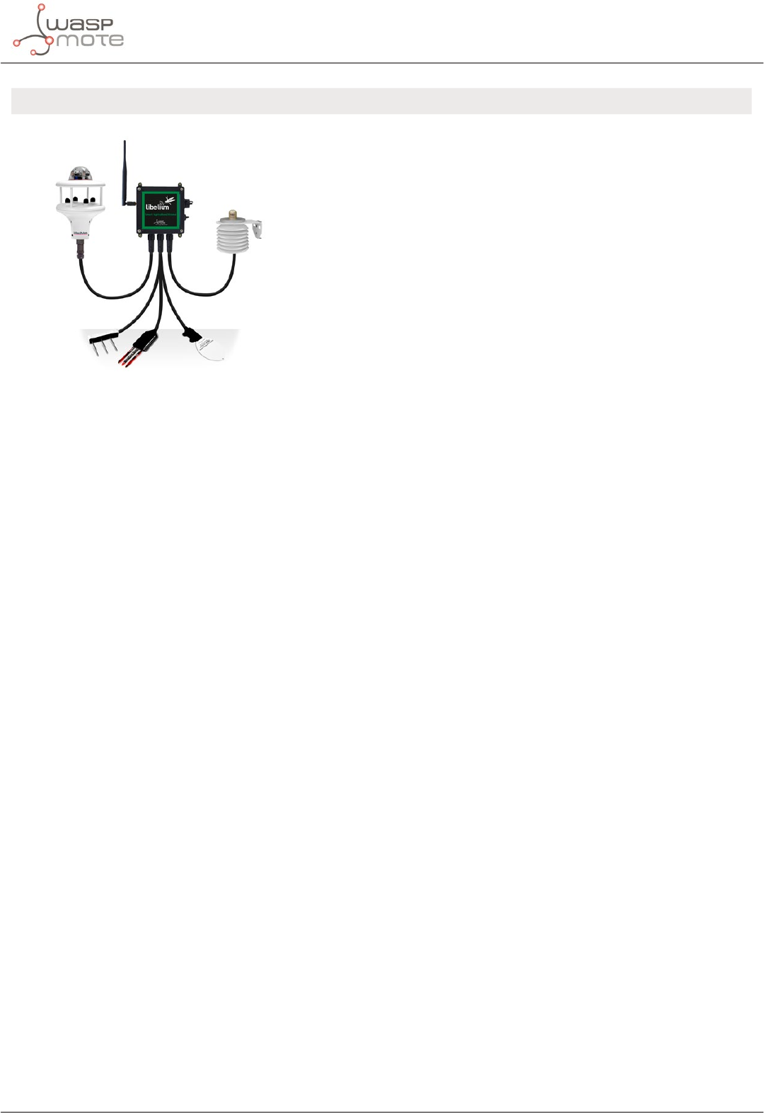
-80- v8.2
Sensors
AGRICULTURE XTREME APPLICATIONS SENSORS
•Precision Agriculture
•Irrigation systems
•Greenhouses
•Weather monitoring
•Soil management
•Accurate fruit observation
• Non-contact surface temperature
measurement SI-411
• Leaf and ower bud temperature
SF-421
• Soil oxygen level O-411
• Shortwave radiation SP-510
• Solar radiation (PAR) SQ-110
• Ultraviolet radiation (UV) SU-100
• Air temperature, humidity and
pressure
• Conductivity, water content and
soil temperature GS3
• Conductivity, water content and
soil temperature 5TE
• Soil temperature and volumetric
water content 5TM
• Soil water potential MPS-6
• Vapor pressure, humidity,
temperature, and atmospheric
pressure in soil and air VP-4
• Leaf wetness Phytos 31
• Trunk Diameter DC2
• Stem Diameter DD-S
• Fruit Diameter DF
• Weather station GMX-100 (PO)
• Weather station GMX-101 (R)
• Weather station GMX-200 (W)
• Weather station GMX-240 (W-PO)
• Weather station GMX-300 (T-H-AP)
• Weather station GMX-301 (T-H-
AP-R)
• Weather station GMX-400 (PO-T-
H-AP)
• Weather station GMX-500 (W-T-
H-AP)
• Weather station GMX-501 (W-T-H-
AP-R)
• Weather station GMX-531 (W-PT-
T-H-AP-R)
• Weather station GMX-541 (W-PO-
T-H-AP-R)
• Weather station GMX-550 (W-x-T-
H-AP)
• Weather station GMX-551 (W-x-T-
H-AP-R)
• Weather station GMX-600 (W-PO-
T-H-AP)
• Luminosity (Luxes)
• Ultrasound (distance
measurement)
• 4-20 mA type (generic input)
• RS-232 type (generic input)
Figure: Plug & Sense! Smart Agriculture Xtreme
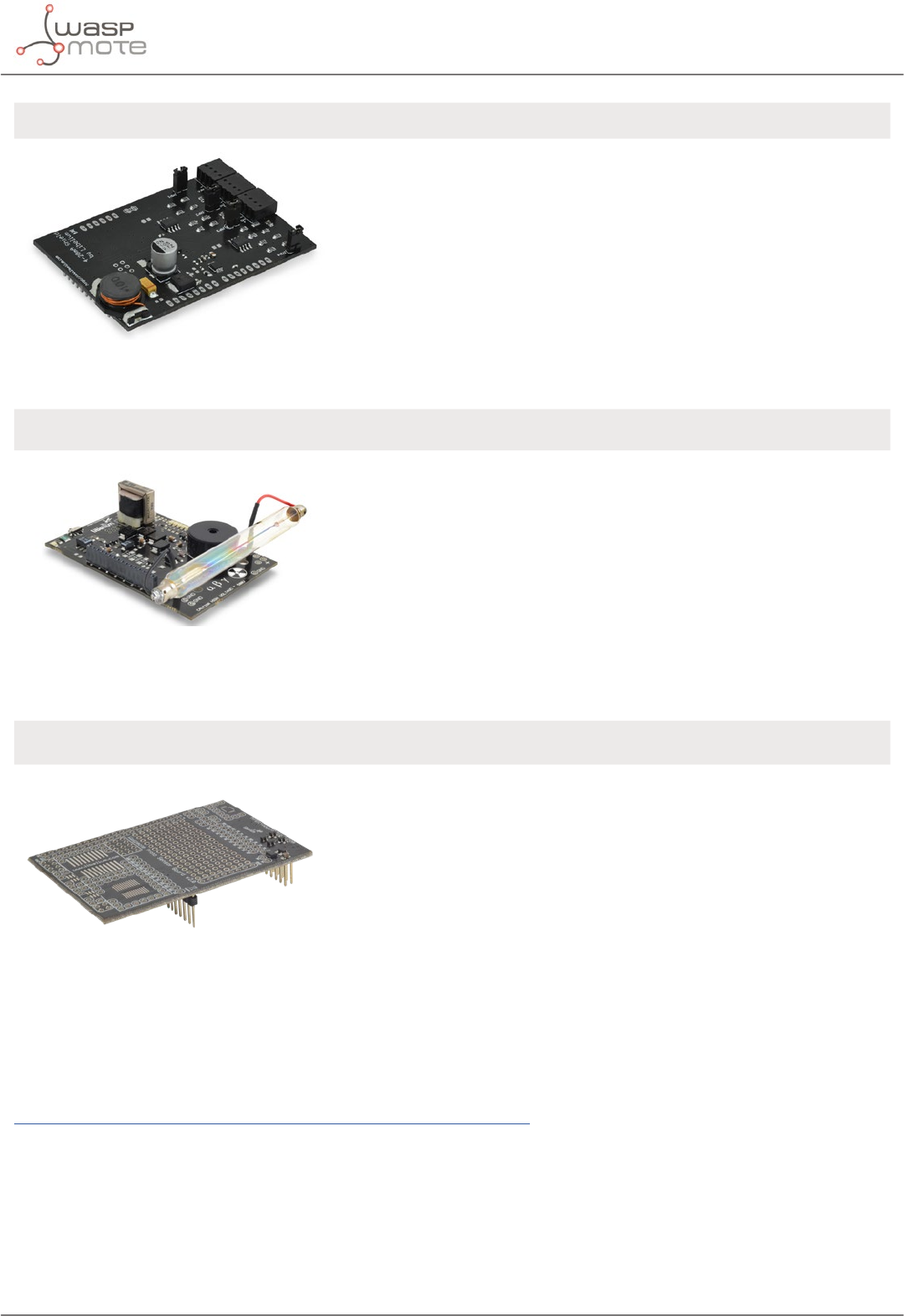
-81- v8.2
Sensors
4-20 mA CURRENT LOOP APPLICATIONS FEATURES
Figure: 4-20 mA Current Loop Board
• Sensors and instruments
• Remote transducers
• Monitoring processes
• Data transmission in industrial
ambients
• Type: Analog
• Media: Twisted Pair
• No. of devices: 4
• Distance: 900m
• Supply: 12 V
The user can choose among a
wide variety of standard sensors
RADIATION APPLICATIONS SENSORS
Figure: Radiation Board
• Monitor the radiation levels
wirelessly without compromising
the life of the security forces
• Create prevention and control
radiation networks in the
surroundings of a nuclear plant
• Measure the amount of Beta and
Gamma radiation in specic areas
autonomously
• Geiger tube [β, γ]
(Beta and Gamma)
PROTOTYPING SENSOR APPLICATIONS
Figure: Prototyping Sensor Board
• Prepared for the integration of
any kind of sensor.
• Pad Area
• Integrated Circuit Area
• Analog-to-Digital Converter
(16b)
It is possible to nd more detailed information in the manual for each board at:
http://www.libelium.com/development/waspmote/documentation

-82- v8.2
Sensors
8.4. Power
In the sensor connector there are also several power pins, specically GND, 3.3 V and 5 V.
•3V3 SENSOR POWER: 3.3 V power voltage (200 mA maximum) which is controlled from the Waspmote exe-
cution code.
•5V SENSOR POWER: 5 V power voltage (200 mA maximum) which is controlled from the Waspmote execu-
tion code.

-83- v8.2
802.15.4/ZigBee/RF modules
9. 802.15.4/ZigBee/RF modules
Waspmote integrates the Digi’s XBee modules for communication in the ISM (Industrial Scientic Medical) bands.
These modules communicate with the microcontroller using the UART0 or UART1 at 115200 bps.
There are several possible XBee modules distributed by Libelium for integration in Waspmote.
Radio version Frequency Transmission power Sensitivity Range*
XBee-PRO 802.15.4 EU 2.4 GHz 10 dBm -100 dBm 750 m
XBee-PRO 802.15.4 2.4 GHz 18 dBm -100 dBm 1600 m
XBee-PRO DigiMesh 2.4 GHz 18 dBm -100 dBm 1500 m
XBee-PRO ZigBee 2.4 GHz 17 dBm -102 dBm 3200 m
XBee 868LP 863 - 870 MHz 14 dBm -106 dBm 8.4 km
XBee 900HP US 902 - 928 MHz 24 dBm -110 dBm 15.5 km
XBee 900HP BR
902 - 906.8 MHz
915.6 - 928 MHz
24 dBm -110 dBm 15.5 km
XBee 900HP AU 915.6 - 928 MHz 24 dBm -110 dBm 15.5 km
* To determine your range, perform a range test under your operating conditions
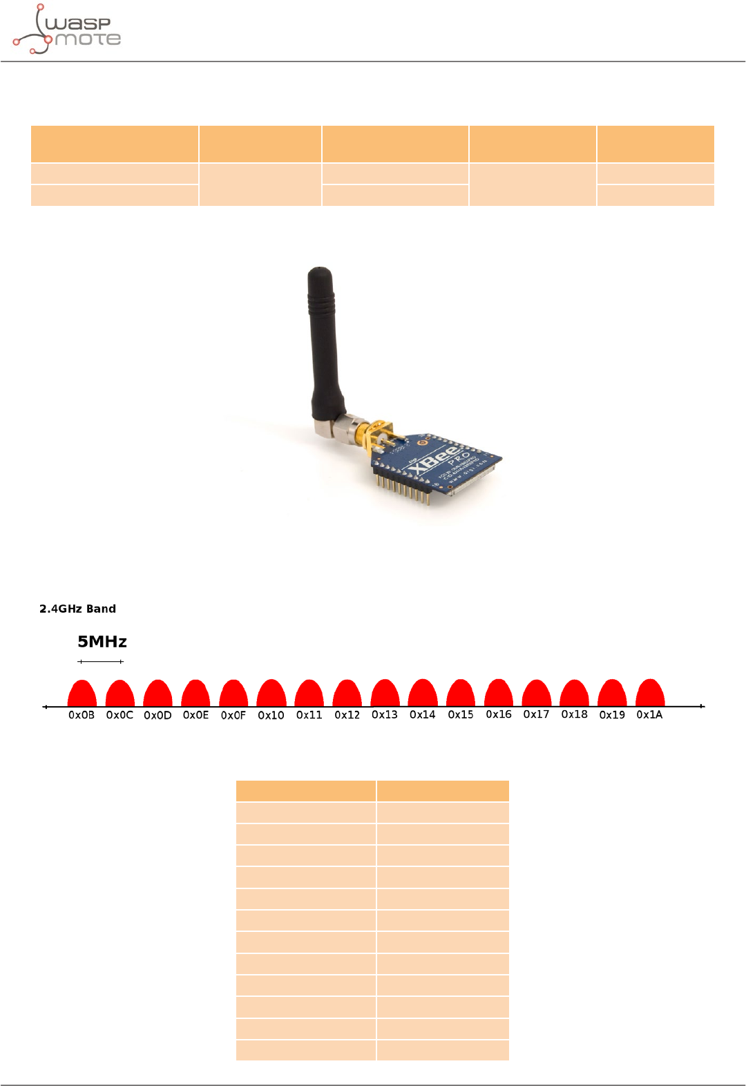
-84- v8.2
802.15.4/ZigBee/RF modules
9.1. XBee-PRO 802.15.4
Radio version Frequency Transmission
power Sensitivity Range*
XBee-PRO 802.15.4 EU 2.4 GHz 10 dBm -100 dBm 750 m
XBee-PRO 802.15.4 18 dBm 1600 m
* To determine your range, perform a range test under your operating conditions
Figure: XBee-PRO 802.15.4
The frequency used is the free band of 2.4 GHz, using 12 channels with a bandwidth of 5 MHz per channel.
Figure: Frequency channels in the 2.4 GHz band
Channel Number Frequency
0x0C – Channel 12 2.405 – 2.410 GHz
0x0D – Channel 13 2.410 – 2.415 GHz
0x0E – Channel 14 2.415 – 2.420 GHz
0x0F – Channel 15 2.420 – 2.425 GHz
0x10 – Channel 16 2.425 – 2.430 GHz
0x11 – Channel 17 2.430 – 2.435 GHz
0x12 – Channel 18 2.435 – 2.440 GHz
0x13 – Channel 19 2.440 – 2.445 GHz
0x14 – Channel 20 2.445 – 2.450 GHz
0x15 – Channel 21 2.450 – 2.455 GHz
0x16 – Channel 22 2.455 – 2.460 GHz
0x17 – Channel 23 2.460 – 2.465 GHz
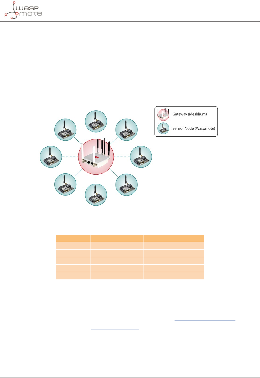
-85- v8.2
802.15.4/ZigBee/RF modules
Figure: Channels used by the XBee modules in 2.4GHz
The XBee-PRO 802.15.4 modules comply with the standard IEEE 802.15.4 which denes the physical level and the
link level (MAC layer). The XBee modules add certain functionalities to those contributed by the standard, such as:
•Node discovery: certain information has been added to the packet headers so that they can discover other
nodes on the same network. It allows a node discovery message to be sent, so that the rest of the network
nodes respond indicating their data (Node Identier, @MAC, @16 bits, RSSI).
•Duplicated packet detection: This functionality is not set out in the standard and is added by the XBee
modules.
The classic topology of this type of network is a star topology, as the nodes establish point to point connections
with brother nodes through the use of parameters such as the MAC or network address.
Figure: Star topology
Regarding the transmission power, it can be adjusted to several values depending on the radio version:
Parameter XBee-PRO 802.15.4 XBee-PRO 802.15.4 EU
0 10 dBm -3 dBm
1 12 dBm -3 dBm
2 14 dBm 2 dBm
3 16 dBm 8 dBm
4 18 dBm 10 dBm
Figure: Transmission power values
Related API libraries: WaspXBeeCore.h, WaspXBeeCore.cpp, WaspXBee802.h, WaspXBee802.cpp
All information about their programming and operation can be found in the 802.15.4 Networking Guide.
All the documentation is located in the Development section in the Libelium website.
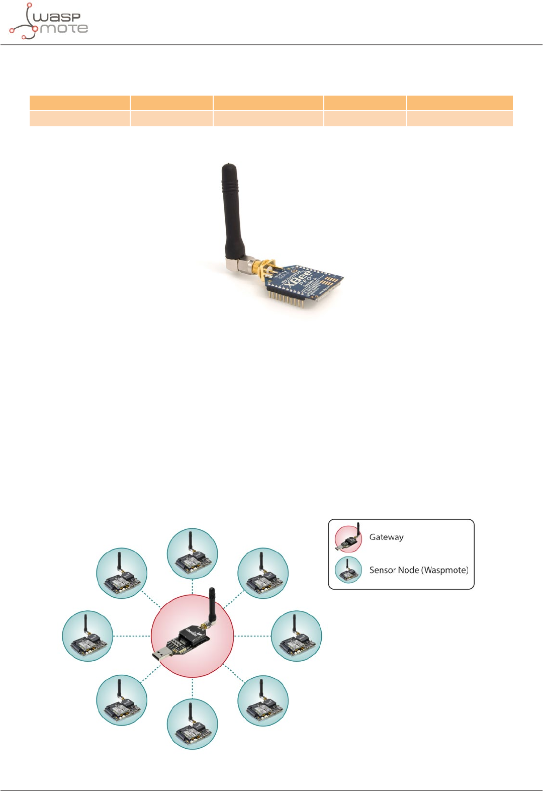
-86- v8.2
802.15.4/ZigBee/RF modules
9.2. XBee-PRO ZigBee
Radio version Frequency Transmission power Sensitivity Range*
XBee-PRO ZigBee 2.4 GHz 17 dBm -102 dBm 3200 m
* To determine your range, perform a range test under your operating conditions
Figure: XBee-PRO ZigBee
As the ZigBee standard is supported in the IEEE 802.15.5 link layer, it uses the same channels as described in the
previous section, with the peculiarity that the XBee-PRO ZigBee model limits the number of channels to 13.
The XBee-PRO ZigBee modules comply with the ZigBee-PRO v2007 standard. These modules add certain
functionalities to those contributed by ZigBee, such as:
•Node discovery: some headings are added so that other nodes within the same network can be discove-
red. It allows a node discovery message to be sent, so that the rest of the network nodes respond indicating
their specic information (Node Identier, @MAC, @16 bits, RSSI).
•Duplicated packet detection: This functionality is not set out in the standard and is added by the XBee
modules.
The topologies in which these modules can be used are: star and tree.
Figure: Star topology
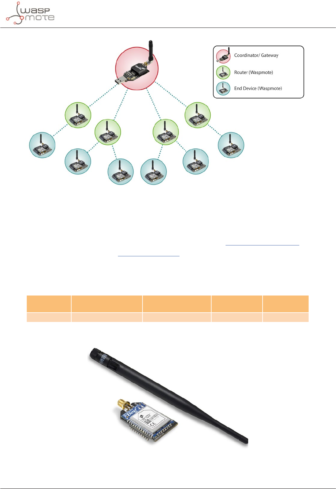
-87- v8.2
802.15.4/ZigBee/RF modules
Figure: Tree topology
Regarding the transmission power, it cannot be adjusted because it is always set to 17 dBm.
Related API libraries: WaspXBeeCore.h, WaspXBeeCore.cpp, WaspXBeeZB.h, WaspXBeeZB.cpp
All information about their programming and operation can be found in the ZigBee Networking Guide.
All the documentation is located in the Development section in the Libelium website.
9.3. XBee 868LP
Radio
version
Frequency Transmission power Sensitivity Range*
XBee 868LP 863 - 870 MHz 14 dBm -106 dBm 8.4 km
* To determine your range, perform a range test under your operating conditions
Figure: XBee 868LP
Note: The XBee 868 MHz module is provided with 4.5dBi antenna, which enables maximum range.
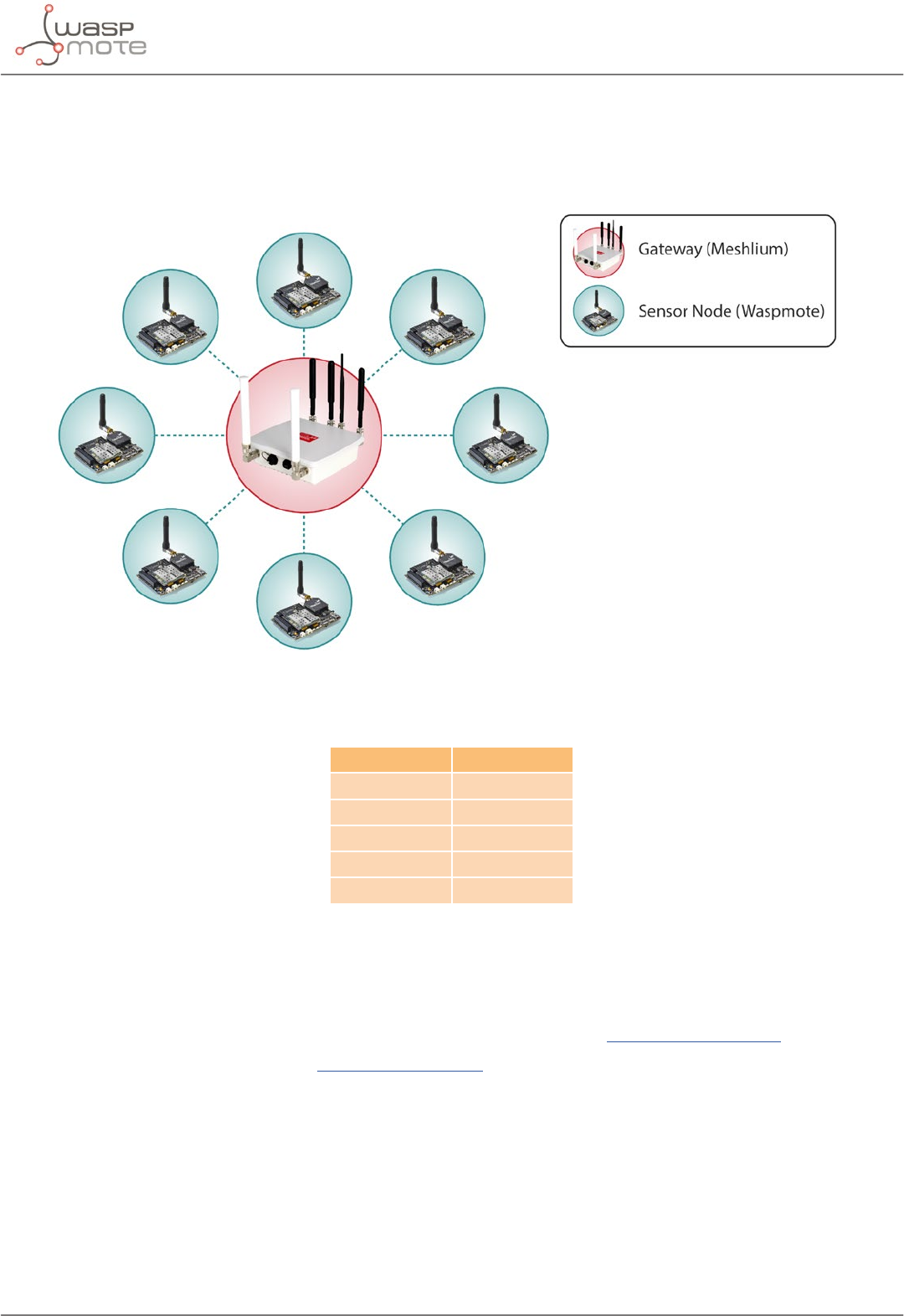
-88- v8.2
802.15.4/ZigBee/RF modules
The frequency used is the 868 MHz band, using 30 software selectable channels. Channels are spaced 100 kHz
apart. The transmission rate is 10 kbps.
The classic topology for this type of network is a star topology, as the nodes can establish point-to-point
connections with brother nodes through the use of the MAC address.
Figure: Star topology
Regarding the transmission power, it can be adjusted to several values:
Parameter XBee 868LP
0 3 dBm
1 7 dBm
2 10 dBm
3 12 dBm
4 14 dBm
Figure: Transmission power values
Related API libraries: WaspXBeeCore.h, WaspXBeeCore.cpp, WaspXBee868LP.h, WaspXBee868LP.cpp
All information about their programming and operation can be found in the 868 Networking Guide.
All the documentation is located in the Development section in the Libelium website.
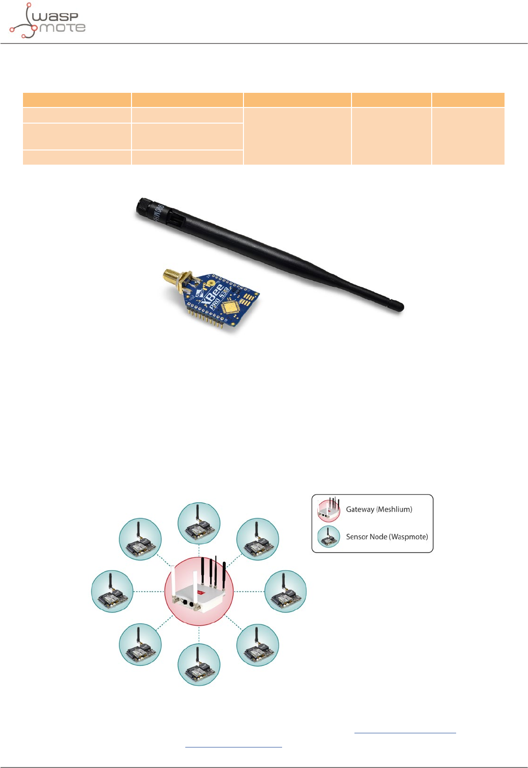
-89- v8.2
802.15.4/ZigBee/RF modules
9.4. XBee-PRO 900HP
Radio version Frequency Transmission power Sensitivity Range*
XBee-PRO 900HP US 902 - 928 MHz
24 dBm -110 dBm 15.5 kmXBee-PRO 900HP BR 902 - 906.8 MHz
915.6 - 928 MHz
XBee-PRO 900HP AU 915.6 - 928 MHz
* To determine your range, perform a range test under your operating conditions
Figure: XBee-PRO 900HP
The frequency used is the 900 MHz band, using 64 software selectable channels. Channels are spaced 400 kHz
apart. The transmission rate is 10 kbps. There are dierent versions of the XBee 900HP: USA & Canada, Brazil and
Australia.
The dierent versions dier mainly in the available channels, which are hard-coded in the XBee. Be aware that it is
not possible to change from one version to other with just a rmware change. According to the country where
the user is located, a dierent version must be chosen.
The classic topology for this type of network is a star topology, as the nodes can establish point-to-point connections
with brother nodes through the use of parameters such as the MAC address or that of the network.
Figure: Star topology
API libraries: WaspXBeeCore.h, WaspXBeeCore.cpp, WaspXBee900HP.h, WaspXBee900HP.cpp
All information about their programming and operation can be found in the 900 Networking Guide.
All the documentation is located in the Development section in the Libelium website.
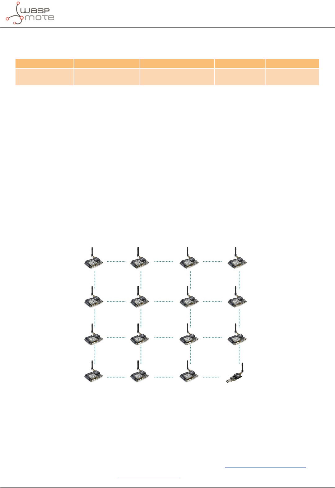
-90- v8.2
802.15.4/ZigBee/RF modules
9.5. XBee-PRO DigiMesh
Radio version Frequency Transmission power Sensitivity Range*
XBee-PRO
DigiMesh
2.4 GHz 18 dBm -100 dBm 1500 m
* To determine your range, perform a range test under your operating conditions
The XBee-PRO 802.15.4 modules can use an optional rmware called DigiMesh. So the modules can create mesh
networks instead of the usual point-to-point topology. This rmware has been developed by Digi in order to
allow the modules to sleep, synchronize themselves and work on equal terms, avoiding the use of node routers
or coordinators that have to be permanently powered on. Characteristics of the implemented protocol:
•Self healing: any node can join or leave the network at any moment.
•All nodes are equal: there are no father-son relationships.
•Silent protocol: reduced routing heading due to using a reactive protocol similar to AODV (Ad hoc On-
Demand Vector Routing).
•Route discovery: instead of keeping a route map, routes are discovered when they are needed.
•Selective ACKs: only the recipient responds to route messages.
•Reliability: the use of ACKs ensures data transmission reliability.
•Sleep modes: low energy consumption modes with synchronization to wake at the same time.
The classic topology of this type of network is mesh, as the nodes can establish point-to-point connections with
brother nodes through the use the MAC address doing multi-hop connections when it is necessary.
Figure: Mesh topology
The XBee DigiMesh modules share the hardware module with the XBee-PRO 802.15.4. So it is possible to change
the rmware of this kind of modules from one to another and vice versa (this can be done with a Gateway). For
this reason, the characteristics related to the hardware are the same.
The XBee DigiMesh modules are based on the standard IEEE 802.15.4 that supports functionalities enabling mesh
topology use.
Related API libraries: WaspXBeeCore.h, WaspXBeeCore.cpp, WaspXBeeDM.h, WaspXBeeDM.cpp
All information about their programming and operation can be found in the DigiMesh Networking Guide.
All the documentation is located in the Development section in the Libelium website.
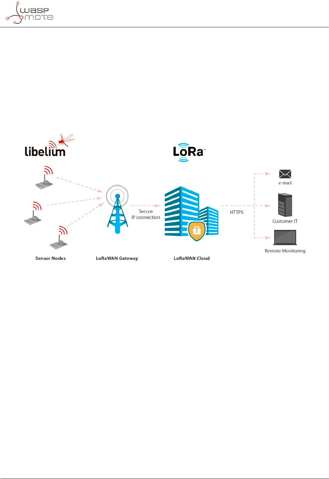
-91- v8.2
LoRaWAN modules
10. LoRaWAN modules
LoRaWAN is a Low Power Wide Area Network (LPWAN) specication intended for wireless battery-operated
devices in regional, national or global network. LoRaWAN target key requirements of Internet of things such
as secure bi-directional communication, mobility and localization services. This standard will provide seamless
interoperability among smart Things without the need of complex local installations and gives back the freedom
to the user, developer, businesses enabling the role out of Internet of Things.
LoRaWAN network architecture is typically laid out in a star-of-stars topology in which gateways is a transparent
bridge relaying messages between end-devices and a central network server in the back-end. Gateways
are connected to the network server via standard IP connections while end-devices use single-hop wireless
communication to one or many gateways.
Figure: LoRaWAN network
Communication between end-devices and gateways is spread out on dierent frequency channels and data rates.
The selection of the data rate is a trade-o between communication range and message duration. Due to the
spread spectrum technology, communications with dierent data rates do not interfere with each other and
create a set of “virtual” channels increasing the capacity of the gateway. To maximize both battery life of the end-
devices and overall network capacity, the LoRaWAN network server is managing the data rate and RF output for
each end-device individually by means of an adaptive data rate (ADR) scheme.
National wide networks targeting Internet of Things such as critical infrastructure, condential personal data or
critical functions for the society has a special need for secure communication. This has been solved by several
layer of encryption.
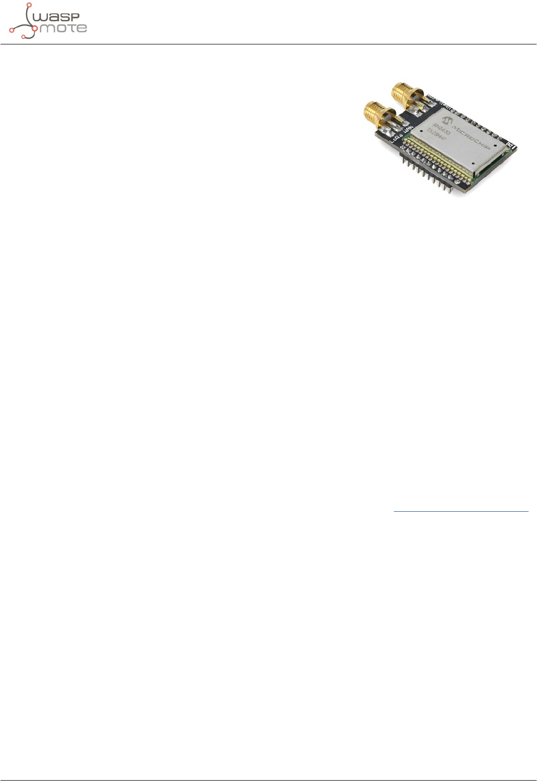
-92- v8.2
LoRaWAN modules
Protocol: LoRaWAN 1.0, Class A
LoRaWAN-ready
Frequency:
•LoRaWAN EU module: 868 MHz and 433 MHz ISM bands
•LoRaWAN US module: 902-928 MHz ISM band
•LoRaWAN AU module: 915-928 MHz ISM band
•LoRaWAN IN module: 865-867 MHz ISM band
•LoRaWAN ASIA-PAC / LATAM module: 923 MHz ISM band
TX power:
•LoRaWAN EU module: up to 14 dBm
•LoRaWAN US module: up to 18.5 dBm
•LoRaWAN AU module: up to 18.5 dBm
•LoRaWAN IN module: up to 18.5 dBm
•LoRaWAN ASIA-PAC / LATAM module: up to 18.5 dBm
Sensitivity: down to -136 dBm
Range: >15 km at suburban and >5 km at urban area. Typically, each base station covers some km. Check the
LoRaWAN Network in your area.
Chipset consumption:
•LoRaWAN EU module: 38.9 mA
•LoRaWAN US module: 124.4 mA
•LoRaWAN AU module: 124.4 mA
•LoRaWAN IN module: 124.4 mA
•LoRaWAN ASIA-PAC / LATAM module: 124.4 mA
Radio data rate:
•LoRaWAN EU module: from 250 to 5470 bps
•LoRaWAN US module: from 250 to 12500 bps
•LoRaWAN AU module: from 250 to 12500 bps
•LoRaWAN IN module: from 250 to 12500 bps
•LoRaWAN ASIA-PAC / LATAM module: from 250 to 12500 bps
Receiver: purchase your own base station or use networks from LoRaWAN operators
Related API libraries: WaspLoRaWAN.h, WaspLoRaWAN.cpp
All the information about their programming and operation can be found in the LoRaWAN Networking Guide
available at Development section of Libelium website.
Figure: LoRaWAN EU module
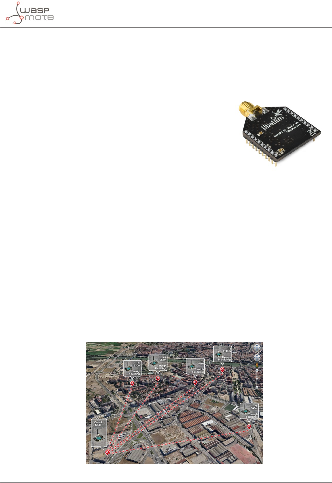
-93- v8.2
LoRa module
11. LoRa module
•Protocol: LoRa “raw”. P2P links (node to node).
•Model: Semtech SX1272
•Frequencies available: 860-1000 MHz, ts both 868 (Europe) and 900 MHz (USA) ISM bands
•Max TX power: 14 dBm
•Sensitivity: -137 dBm
•Range:
-Line of Sight: 21+ km / 13.4+ miles (LoS and Fresnel zone clearance)
- Non Line of Sight: 2+ km / 1.2+ miles (nLoS going through buildings,
urban environment)
•Antenna:
- 868 / 900 MHz: 4.5 dBi
- Connector: RPSMA
•Encryption: AES 128/192/256b (performed by Waspmote API)
•Control Signal: RSSI
•Topology: Star
•Receiver/Central node: Special Gateway LoRa (SPI) or another Waspmote unit
Note: The LoRa module is provided with a 4.5 dBi antenna, which enables maximum range.
This radio module provides an optimum range performance, thanks to the excellent receiver sensitivity that the
LoRa™ technology oers. Besides, Libelium developed a library which enables addressable, reliable and robust
communications with ACK, re-tries or time-outs strategies.
The user can set any frequency in the 868 and 900 MHz bands, with pre-dened channels. The use of this module
is allowed in virtually any country.
Encryption is implemented in the application level, thanks to the Waspmote’s AES library. The payload inside the
wireless packet is encrypted so only nodes knowing the key can read the content. The encryption activation is as
simple as running one of our LoRa with AES encryption examples.
The topology for this type of network is a star topology, as the nodes can establish point-to-point connections
with brother nodes, normally with the central one.
Related API libraries: WaspSX1272.h, WaspSX1272.cpp
All information about programming the LoRa module can be found in the SX1272 LoRa Networking Guide.
All the documentation is located in the Development section in the Libelium website.
Figure: Star topology
Figure: LoRa module
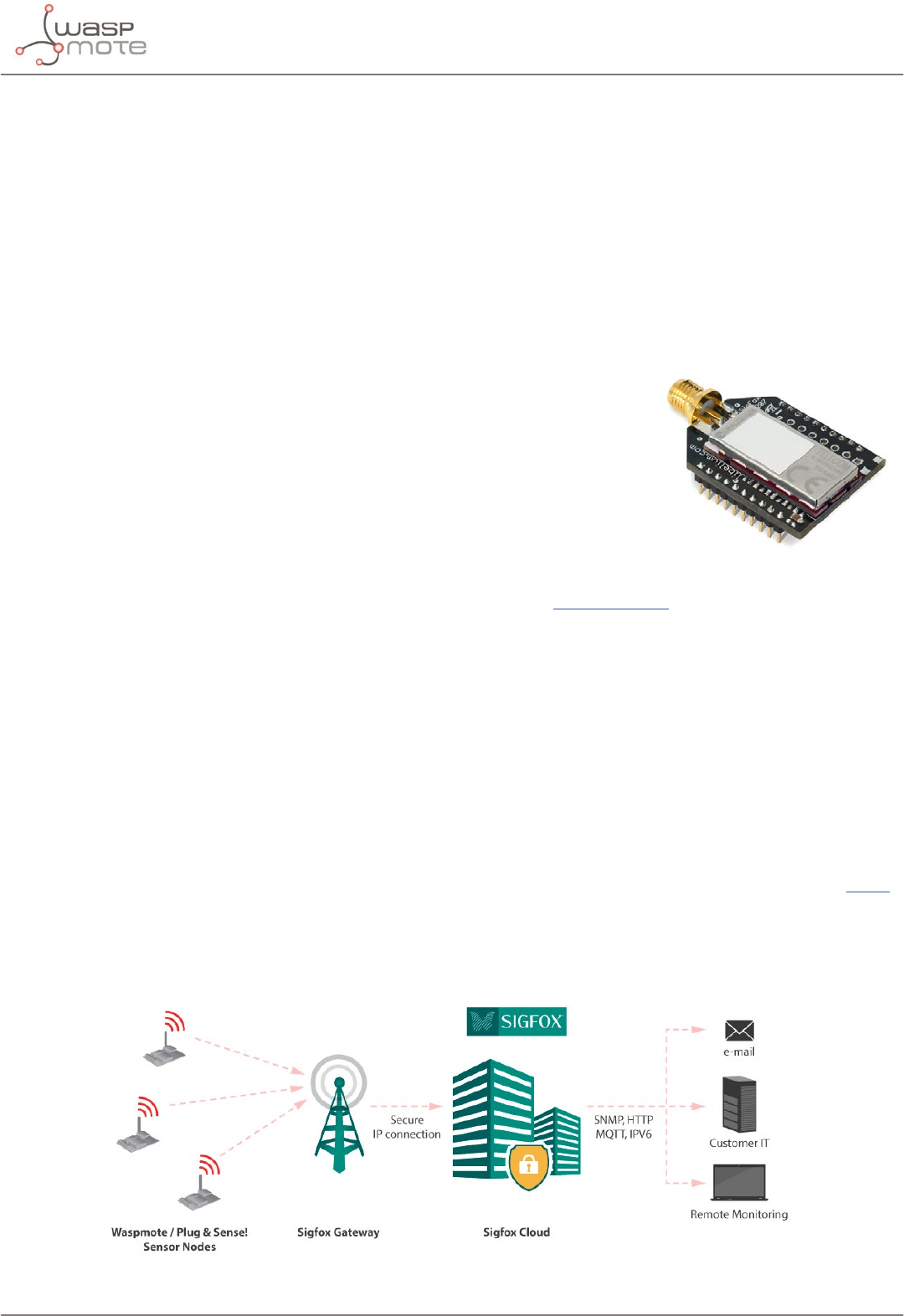
-94- v8.2
Sigfox modules
12. Sigfox modules
Sigfox is a private company that aims to build a worldwide network especially designed for IoT devices. The
network is cellular, with thousands of base stations deployed in each country. Sigfox technology oers very long
ranges for low-power, battery-constrained nodes. Sigfox is great for very simple and autonomous devices which
need to send small amounts of data to this ubiquitous network, taking advantage on the Sigfox infrastructure.
So Sigfox is similar to cellular (GSM-GPRS-3G-NB-IoT-Cat-M-4G) but is more energy-ecient, and the annual fees
are lower.
Sigfox uses a UNB (Ultra Narrow Band) based radio technology to connect devices to its global network. The use
of UNB is key to providing a scalable, high-capacity network, with very low energy consumption, while maintaining
a simple and easy to rollout star-based cell infrastructure.
•Frequency
-Sigfox EU module: ISM 868 MHz
-Sigfox US module: ISM 900 MHz
-Sigfox AU / APAC / LATAM module: ISM 900 MHz
•TX power
-Sigfox EU module: up to 16 dBm
-Sigfox US module: up to 24 dBm
-Sigfox AU / APAC / LATAM module: up to 24 dBm
•ETSI limitation: 140 messages of 12 bytes, per module per day
•Range: Typically, each base station covers some km. Check the Sigfox network.
•Chipset consumption
-Sigfox EU module: TX 51 mA @ 14 dBm
-Sigfox US module: TX 230 mA @ 24 dBm
-Sigfox AU / APAC / LATAM module: TX 230 mA @ 24 dBm
•Radio data rate: 100 bps
•Receive sensitivity: -126 dBm
•Sigfox certicate: Class 0u (the highest level)
The network operates in the globally available ISM bands (license-free frequency bands) and co-exists in these
frequencies with other radio technologies, but without any risk of collisions or capacity problems.
Sigfox is being rolled out worldwide. It is the responsibility of the system integrator to consult the catalog of SNOs
(Sigfox Network Operators) for checking coverage in the deployment area.
The Sigfox back-end provides a web application interface for device management and conguration of data
integration, as well as standards based web APIs to automate the device management and implement the data
integration.
Figure: Sigfox network
Figure: Sigfox module


-96- v8.2
WiFi PRO module
13. WiFi PRO module
The WiFi PRO module oers and supports large variety of features, for example:
•Ten simultaneous TCP/UDP sockets
•DHCP client/server
•DNS client
•HTTP client
•HTTPS client
•FTP client
•NTP client
•Multiple SSIDs
•Roaming mode
•OTA feature. Refer to the Over the Air Programming Guide for more information.
The WiFi PRO module supports the SSL3/TLS1 protocol for secure sockets. On the WLAN interface it supports WEP,
WPA and WPA2 WiFi encryption.
The WiFi PRO module may connect to any standard router which is congured as Access Point (AP) and then send
data to other devices in the same network such as laptops and smart phones. Besides, they can send data directly
to a web server located on the Internet.
Instead of using a standard WiFi router as AP, the connection may be performed using a Meshlium device as
AP. Meshlium is the multiprotocol router designed by Libelium which is specially recommended for outdoor
applications as it is designed to resist the hardest conditions in real eld deployments. For more information
about Meshlium go to:
http://www.libelium.com/meshlium.
Related API libraries: WaspWiFi_PRO.h, WaspWiFi_PRO.cpp
All information about their programming and operation can be found in the WiFi Networking Guide.
All the documentation is located in the Development section in the Libelium website.
Figure: WiFi module
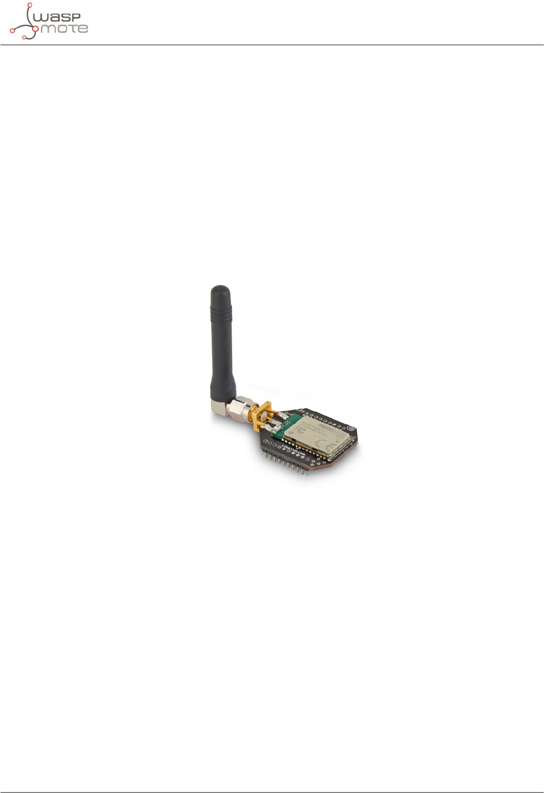
-97- v8.2
Bluetooth Pro module
14. Bluetooth Pro module
Technical specications:
•Bluetooth v2.1 + EDR. Class 2.
•TX power: 3 dBm
•Antenna: 2 dBi
•Up to 250 unique devices in each inquiry
•Received Strength Signal Indicator (RSSI) for each scanned device
•Class of Device (CoD) for each scanned device
•7 power levels [-27 dBm, +3 dBm]
•Scan devices with maximum inquiry time
•Scan devices with maximum number of nodes
•Scan devices looking for a certain user by MAC address
•Classication between pedestrians and vehicles
Figure: Libelium Bluetooth module
Bluetooth uses 79 channels with a bandwidth of 1 MHz per channel. In addition, Adaptive Frequency Hopping
(AFH) is used to enhance the transmissions.
Bluetooth module for device discovery:
The Bluetooth radio module has been specically designed in order to scan up to 250 devices in a single inquiry
(smart phones, tablets, computers, etc). The main purpose is to be able to detect as many Bluetooth users as
possible in the surrounding area.
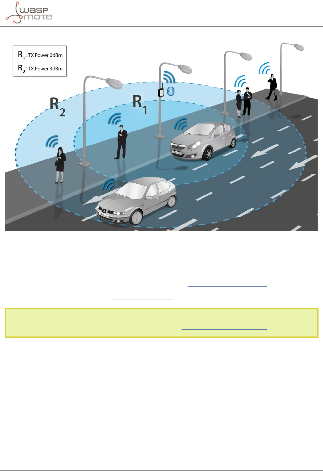
-98- v8.2
Bluetooth Pro module
Figure: Bluetooth module for device discovery
Related API libraries: WaspBT_Pro.h, WaspBT_Pro.cpp
All information on their programming can be found in document: Bluetooth Networking Guide.
All the documentation is located in the Development section in the Libelium website.
Note: If you want to detect iPhone and Android devices using the WiFi interface as well as the Bluetooth radio go
to the “Smartphone Detection” section in the Meshlium website: http://www.libelium.com/meshlium
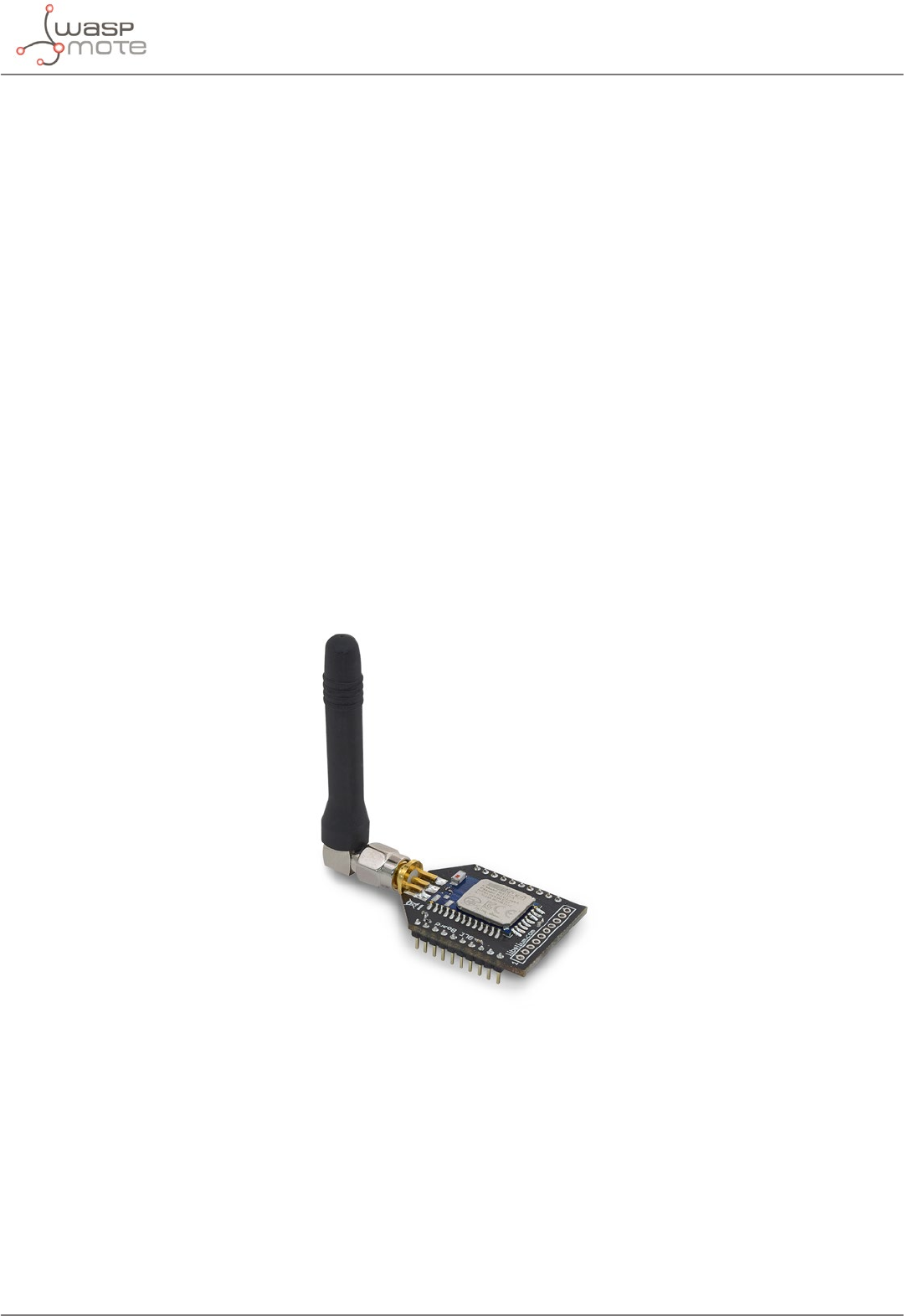
-99- v8.2
Bluetooth Low Energy module
15. Bluetooth Low Energy module
Technical specications:
•Protocol: Bluetooth v.4.0 / Bluetooth Smart
•Chipset: BLE112
•RX Sensitivity: -103 dBm
•TX Power: [-23 dBm, +3 dBm]
•Antenna: 2 dBi/5 dBi antenna options
•Security: AES-128
•Range: 100 meters (at maximum TX power)
•Consumption: sleep (0.4 uA) / RX (8 mA) / TX (36 mA)
•Send broadcast advertisements (iBeacons)
•Connect to other BLE devices as Master / Slave
•Connect with smartphones and tablets
•Set automatic cycles sleep / transmission
•Calculate distance using RSSI values
•Perfect for indoor location networks (RTLS)
•Scan devices with maximum inquiry time
•Scan devices with maximum number of nodes
•Scan devices looking for a certain user by MAC address
Figure: Waspmote Bluetooth Low Energy module
BLE modules use the 2.4 GHz band (2402 MHz – 2480 MHz). It has 37 data channels and 3 advertisement channels,
with a 2MHz spacing.

-100- v8.2
Bluetooth Low Energy module
Figure: Channel distribution on the BLE standard
In the same way as Bluetooth classic modules, other BLE modules can be identied by their MAC address and
public name. Also, the RSSI is provided to show the quality of each link.
Related API libraries: WaspBLE.h, WaspBLE.cpp.
All information on their programming can be found in document: Bluetooth Low Energy Networking Guide.
All the documentation is located in the Development section in the Libelium website.
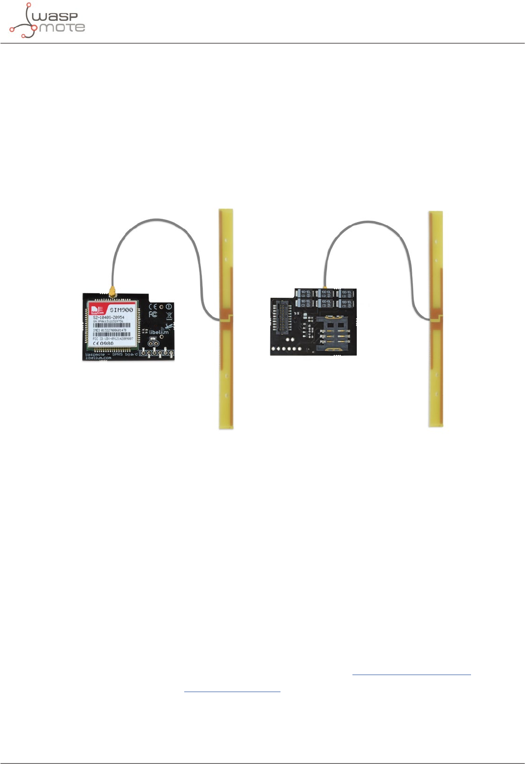
-101- v8.2
GPRS module
16. GPRS module
Waspmote can integrate a GSM (Global System for Mobile communications) / GPRS (General Packet Radio Service)
module to enable communication using the mobile telephone network.
•Model: SIM900 (SIMCom)
•Quadband: 850/900/1800/1900 MHz
•TX power: 2 W (Class 4) 850/900 MHz, 1 W (Class 1) 1800/1900 MHz
•Sensitivity: -109 dBm
•Antenna connector: U.FL
•External antenna: 0 dBi
Figure: GPRS module
This module can carry out the following tasks:
•Making/Receiving calls
•Making ‘x’-second lost calls
•Sending/Receiving SMS
•Single connection and multiple connections TCP/IP and UDP/IP clients
•TCP/IP server
•HTTP service
•FTP service (downloading and uploading les)
This model uses the UART1 at a baudrate of 57600 bps speed to communicate with the microcontroller.
Related API libraries: WaspGPRS_Pro.h, WaspGPRS_Pro.cpp , WaspGPRS_Pro_core.h and WaspGPRS_Pro_core.
cpp
All information about their programming and operation can be found in the GPRS Programming Guide.
All the documentation is located in the Development section in the Libelium website.
Note: A rechargeable battery must be always connected when using this module (USB power supply is not enough).
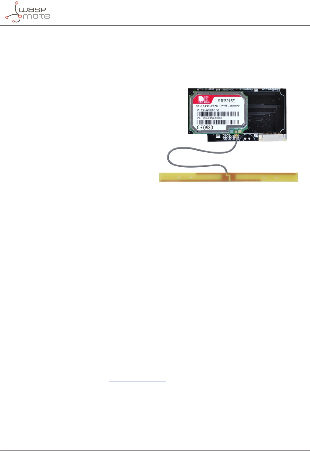
-102- v8.2
3G module
17. 3G module
Waspmote can integrate a UMTS (Universal Mobile Telecommunication System based in WCDMA technology) /
GPRS (General Packet Radio Service) module to enable communication using the 3G/GPRS mobile telephone
network.
•Model: SIM5215 (SIMCom)
•Versions: Europe and America/Australia
•Europe version:
-Dual-Band: 900/2100 MHz
-Tri-Band: 850/900/1800 MHz
•America/Australia version:
-Dual-Band: 850/1900 MHz
-Quad-Band: 850/900/1800/1900 MHz
•WCDMA (downlink): up to 384 kbps
•WCDMA (uplink): up to 384 kbps
•TX power:
-UMTS 850/900/1900/2100: 0.25 W
-GSM 850/900: 2 W
-DCS 1800 / PCS 1900: 1 W
•Sensitivity: -106 dBm
•Antenna connector: U.FL
•External antenna: 0 dBi
This module can carry out the following tasks:
•Support microSD card up to 32 GB
•64 MB of internal storage space
•Making/Receiving calls
•Making ‘x’-second lost calls
•Sending/Receiving SMS
•Single connection and multiple connections TCP/IP and UDP/IP clients
•TCP/IP server
•HTTP and HTTPS service
•FTP and FTPS service (downloading and uploading les)
•Sending/receiving email (SMTP/POP3)
This model uses the UART1 at a baudrate of 115200 bps to communicate with the microcontroller.
Related API libraries: Wasp3G.h, Wasp3G.cpp
All information about programming and operation can be found in the 3G/GPRS Networking Guide.
All the documentation is located in the Development section of Libelium website.
Note: A rechargeable battery must be always connected when using this module (USB power supply is not enough).
Figure: 3G module
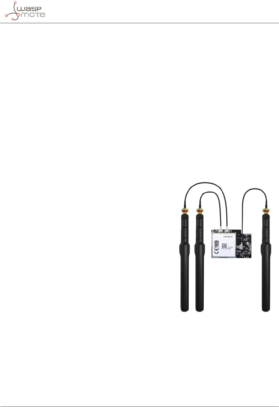
-103- v8.2
4G module
18. 4G module
The 4G module enables the connectivity to high speed LTE, HSPA+, WCDMA cellular networks in order to make
possible the creation of the next level of worldwide compatible projects inside the new “Internet of Things” era.
This communication module is specially oriented to work with Internet servers, implementing internally several
application layer protocols, which make easier to send the information to the cloud. We can make HTTP navigation,
downloading and uploading content to a web server. We can also set secure connections using SSL certicates
and setting TCP/IP private sockets. In the same way, the FTP protocol is also available which is really useful when
your application requires handling les.
The module includes a GPS/GLONASS receiver, able to perform geolocation services using NMEA sentences,
oering information such as latitude, longitude, altitude and speed; that makes it perfect to perform tracking
applications.
The 4G module oers the maximum performance of the 4G network as it uses 2 dierent antennas (normal +
diversity) for reception (MIMO DL 2x2), choosing the best received signal at any time and getting a maximum
download speed of 100 Mbps.
We chose the LE910 chipset family from Telit as it comprises the most complete 4G/LTE set of variants released
up to date. It counts with many dierent models, each one specically designed for one market but all of them
with the same footprint:
•LE910-EU (Europe/Brazil): CE, GCF, ANATEL
•LE910-NAG (US / Canada): FCC, IC, PTCRB, AT&T approved
•LE910-AU V2 (Australia): RCM, Telstra approved → [Available in Q3
2016]
Model: LE910 (Telit)
Versions:
•Europe/Brazil
•America
•Australia
Europe/Brazil version:
•2G: 900/1800 MHz
•WCDMA: 850/900/2100 MHz
•LTE: 800/1800/2600 MHz
America version:
•2G: 850/1900 MHz
•WCDMA: 850/1900 MHz
•LTE: 700/850/1700/1900 MHz
Australia version:
•4G: 700/1800/2600 MHz
LTE (downlink):
•Europe/Brazil version up to 100 Mbps
•America version up to 100 Mbps
•Australia version up to 150 Mbps
LTE (uplink): up to 50 Mbps
Figure: 4G module

-104- v8.2
4G module
TX power:
•Europe/Brazil:
-Class 4 (2 W, 33 dBm) @ GSM 900
-Class 1 (1 W, 30 dBm) @ GSM 1800
-Class E2 (0.5 W, 27 dBm) @ EDGE 900
-Class E2 (0.4 W, 26 dBm) @ EDGE 1800
-Class 3 (0.25 W, 24 dBm) @ UMTS
-Class 3 (0.2 W, 23 dBm) @ LTE
•America:
-Class 4 (2 W, 33 dBm) @ GSM 900
-Class 1 (1 W, 30 dBm) @ GSM 1800
-Class E2 (0.5 W, 27 dBm) @ EDGE 900
-Class E2 (0.4 W, 26 dBm) @ EDGE 1800
-Class 3 (0.25 W, 24 dBm) @ UMTS
-Class 3 (0.2 W, 23 dBm) @ LTE
•Australia:
-Class 3(0.2W, 23 dBm) @ LTE
Antenna connector:
•U.FL for main antenna
•U.FL for cellular diversity antenna
•U.FL for GPS antenna (only for Europe/Brazil and America modules)
External antenna: +5 dBi
GPS: GPS feature is supported only in Europe/Brazil and America versions
This module can carry out the following tasks:
•Sending/Receiving SMS
•Multisocket up to 6 TCP/IP and UDP/IP clients
•TCP/IP server
•TCP SSL
•HTTP service
•FTP service (downloading and uploading les)
•Sending/receiving email (SMTP/POP3)
Certications:
•LE910-EUG (Europe / Brazil): CE, GCF, ANATEL
•LE910-NAG (US / Canada): FCC, IC, PTCRB, AT&T approved
•LE910-AU V2 (Australia): RCM, Telstra approved
•LE910-SKG (South Korea): KCC, SK Telecom approved
•LE910-JN V2 / LE910-JK V2 (Japan): NTT DoCoMo, KDDi
•
This model uses the UART1 at a baudrate of 115200 bps to communicate with the microcontroller.
Related API libraries: Wasp4G.h, Wasp4G.cpp
All information about programming and operation can be found in the 4G Networking Guide.
All the documentation is located in the Development section of Libelium website.
Note: A rechargeable battery must be always connected when using this module (USB power supply is not enough).

-105- v8.2
NB-IoT / Cat-M module
19. NB-IoT / Cat-M module
Due to the popularity of Low Power Wide Area Networks (LPWAN) such as LoRaWAN or Sigfox in the IoT industry,
the traditional cellular networks like 4G have been ousted as the best choice, specially when low cost, low power
consumption and long range are key characteristics. As a response to this market demand, the 3GPP association
published 2 cellular narrow band IoT standards in the release 13: NB-IoT (“narrow band for the Internet of Things”)
and Cat-M (“category machine”). They are also known as LTE Cat-NB1 and LTE Cat-M1. Libelium has integrated the
BG96 chipset by Quectel to meet this requirement.
This module has been included in the Waspmote ecosystem as an OEM development kit, where the NB-IoT and
the Cat-M connectivities can be easily tested in pilot projects or proof of concepts applications.
The NB-IoT / Cat-M module also includes EGPRS connectivity, allowing to transmit information even if there is no
coverage for NB-IoT or Cat-M and also maintaining ultra-low power consumption. Besides, the most common
Internet protocols like HTTP(S), FTP(S), SSL, TCP or UDP are supported.
Moreover, the module integrates a GNSS engine supporting GPS, BeiDou, Galileo, GLONASS and QZSS systems,
making it suitable for tracking applications where low cost and accurate positioning is needed.
Designed to be plugged on the socket1 of Waspmote, the module can meet almost all requirements for IoT
applications like smart cities, remote monitoring, smart logistics, real-time tracking, etc. Additionally, the NB-IoT /
Cat-M module has a unique global version, allowing the usage all over the world with no fragmentation.
Like other radio modules, Libelium provides a dedicated library for Waspmote and some example codes, which
speed up the testing for the NB-IoT or the Cat-M connectivity with just a few high-level functions, and without
dealing with AT commands. Thus, the development of pilot projects and proof of concepts becomes easy.
Note: It is important to remark that the NB-IoT or Cat-M connectivities require a dedicated SIM card (not
included by default). With a standard SIM card, only the EGPRS connectivity can be tested. Besides, the
network coverage is only present in certain zones and strongly depends on the selected mobile network
operator. It is recommended to check operators coverage in the location where the module will be used.
Model: BG96 (Quectel)
Frequency bands:
•Cat NB1 / Cat M1: LTE FDD: B1/B2/B3/B4/B5/B8/B12/B13/B18/ B19/B20/B25**/B26*/B28
•LTE TDD: B39 (for Cat-M1 only)
•EGPRS: 850/900/1800/1900 MHz
Data:
•Cat-NB1: Max. 32 kbps (DL), Max. 70 kbps (UL)
•Cat-M1: Max. 375 kbps (DL), Max. 375 kbps (UL)
•EDGE: Max. 296 kbps (DL), Max. 236.8 kbps (UL)
•GPRS: Max. 107 kbps (DL), Max. 85.6 kbps (UL)
SMS:
•Point-to-point MO and MT
•SMS Cell Broadcast
•Text and PDU Mode
GNNS:
Embedded GNSS as optional. Supports GPS, GLONASS, BeiDou/Compass, Galileo and QZSS.
Antenna connectors:
•U.FL for main antenna (cellular)
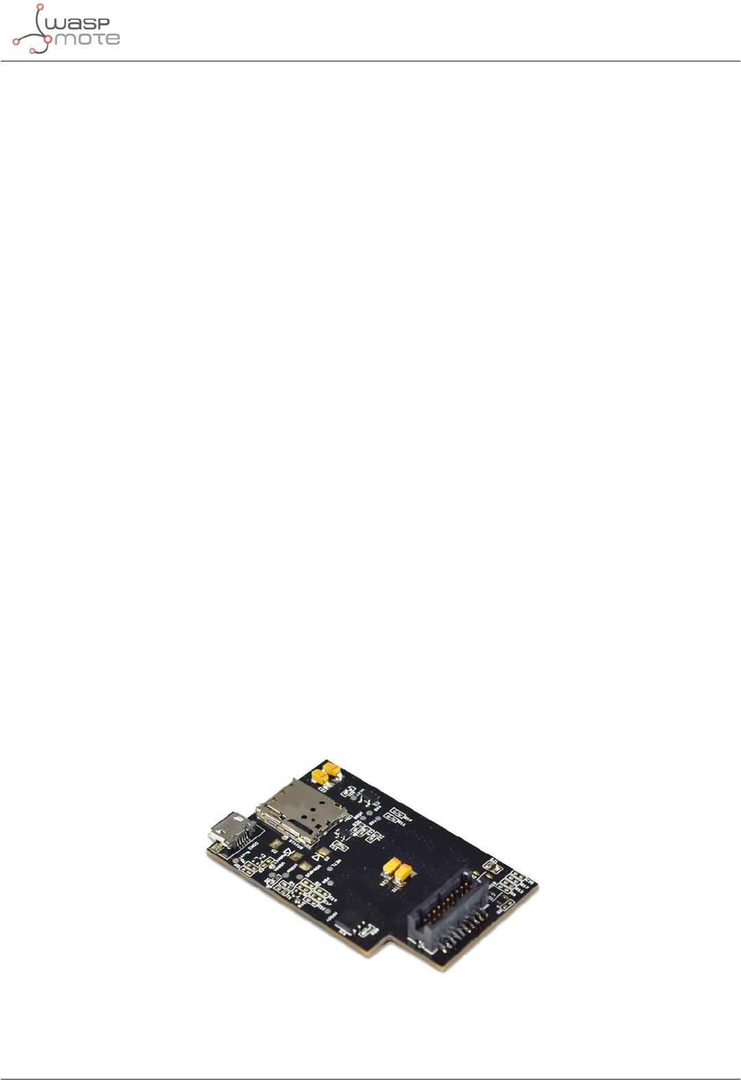
-106- v8.2
NB-IoT / Cat-M module
•U.FL for GNSS antenna
External antenna: 5 dBi
Sensitivity:
•-113 dBm @Cat NB1, CE Level 0
•-107 dBm @Cat M1, 1.4 MHz Bandwidth, CE Mode A
SIM size: Nano-SIM (4FF standard) (not included)
Protocols:
PPP/TCP/UDP/SSL/TLS/FTP(S)/HTTP(S)/NITZ/ PING/MQTT
Actions:
•Sending/receiving SMS
•TCP/IP and UDP/IP clients
•HTTP and HTTPS service (fully secured comms)
Certications:
•GCF/Vodafone (Global)
•CE/Deutsche Telekom (Europe)
•FCC/PTCRB/AT&T/Verizon/T-Mobile*/Sprint* (North America)
•RCM/Telstra (Australia)
•IC/Telus/Bell* (Canada)
•Telefónica (Spain)
•JATE/TELEC/KDDI/SoftBank/DOCOMO* (Japan)
•KC/SKT/LGU+* (Korea)
•IFETEL (Mexico)
•IMDA (Singapore)
•NCC (Taiwan)
•CCC (China)
* Under Development
** LTE B25 will be supported on BG96 with R1.2 hardware version.
Figure: NB-IoT / Cat-M module

-107- v8.2
NB-IoT / Cat-M module
This module uses the UART1 to communicate with the microcontroller.
Related API libraries: WaspBG96.h, WaspBG96.cpp
All information about programming and operation can be found in the NB-IoT / Cat-M Networking Guide.
All the documentation is located in the Development section of Libelium website.
Note: A rechargeable battery must be always connected when using this module (USB power supply is not enough).
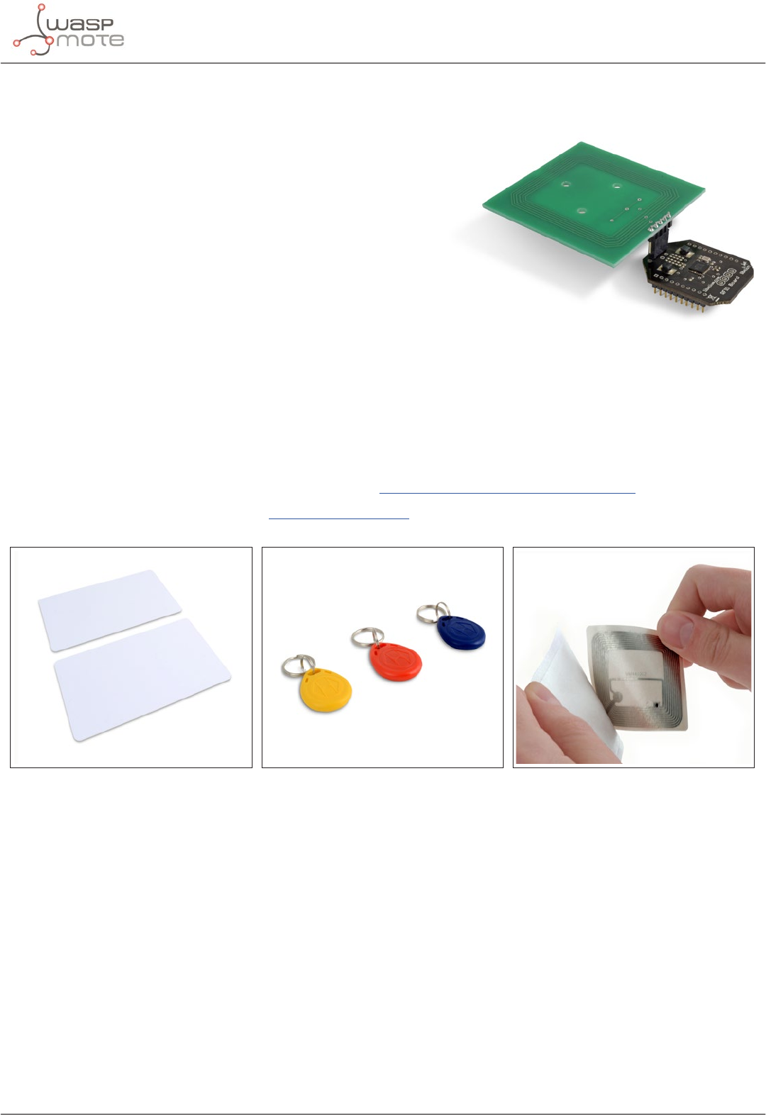
-108- v8.2
RFID/NFC module
20. RFID/NFC module
Features:
•Compatibility: Reader/writer mode supporting ISO 14443A /
MIFARE / FeliCaTM / NFCIP-1
•Distance: 5 cm
•Max capacity: 4 kB
•Tags: cards, keyrings, stickers
Applications:
•Located based services (LBS)
•Logistics (assets tracking, supply chain)
•Access management
•Electronic prepaid metering (vending machines, public transport)
•Smartphone interaction (NFCIP-1 protocol)
Related API libraries: WaspRFID13.cpp , WaspRFID13.h
All information on its programming can be found in the RFID/NFC 13.56MHz Networking Guide.
All the documentation is located in the Development section in the Libelium website.
Figure: RFID cards Figure: RFID keyrings Figure: RFID sticker
Figure: 13.56MHz RFID/NFC module
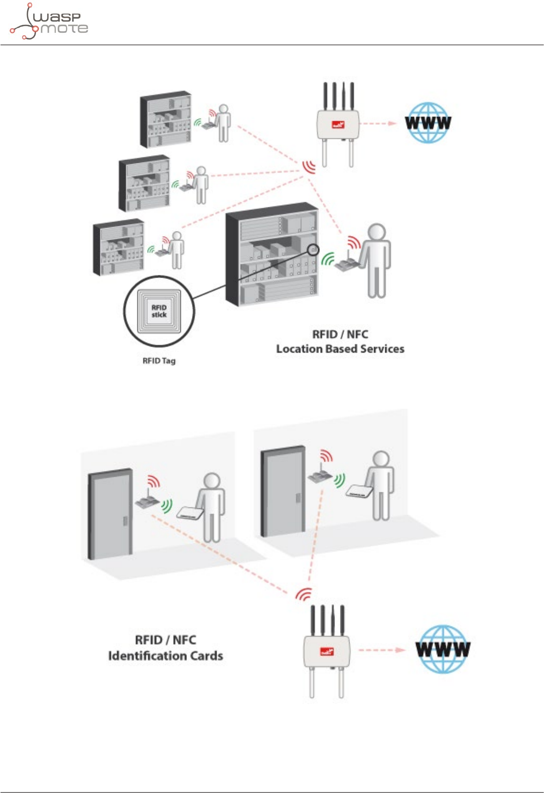
-109- v8.2
RFID/NFC module
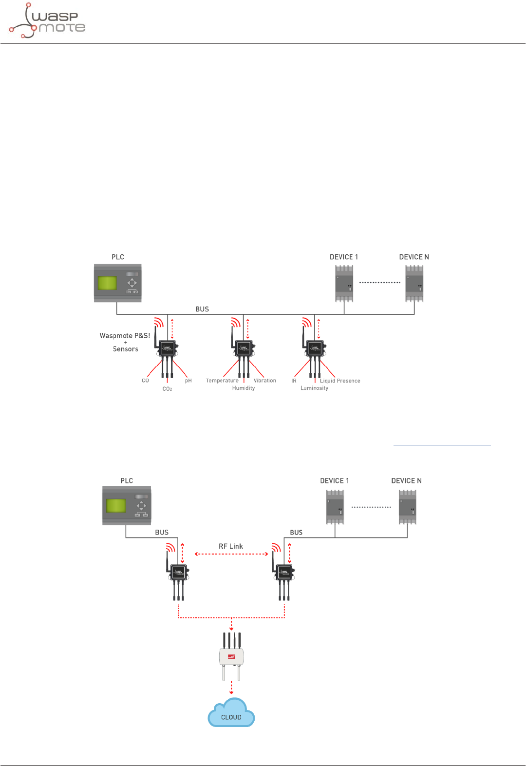
-110- v8.2
Industrial Protocols
21. Industrial Protocols
21.1. Introduction
Libelium oers communication modules for the most common wired communication protocols: RS-485, CAN Bus
and Modbus. These are widely used standards in the industrial and automation market for connecting devices and
sensors, not in a wireless way but with cables. The user can interface Waspmote ecosystem with these protocols.
Waspmote allows to perform 3 main applications:
1º- Connect any sensor to an existing industrial bus
Waspmote can be congured to work as a node in the network, inserting sensor data into the industrial bus already
present. Waspmote can obtain information from more than 100 sensors currently integrated in the platform by
using specic sensor boards (e.g.: CO, CO2, temperature, humidity, acceleration, pH, IR, luminosity, vibration, etc).
This way, the sensor information can be read from any industrial device connected to the bus.
Figure: Module in wireless sensor network applications
2º- Add wireless connectivity to wired buses
Waspmote can be congured to read the information from the bus and send it to the Libelium IoT Gateway using
any of the wireless radio modules available: 802.15.4, ZigBee, DigiMesh, 868 MHz, 900 MHz, LoRa, WiFi, GPRS, 3G,
NB-IoT / Cat-M, 4G, Sigfox, LoRaWAN, Bluetooth Pro, Bluetooth Low Energy and RFID/NFC.
Figure: Waspmote for wire replacement
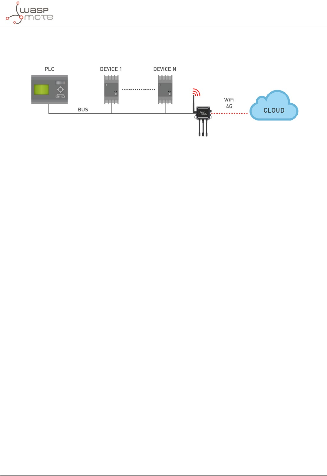
-111- v8.2
Industrial Protocols
3º- Connect to the Cloud industrial devices
Waspmote can be congured to read the information coming from the bus and send it wirelessly directly to the
Cloud using WiFi, GPRS, 3G, NB-IoT / Cat-M or 4G radio interfaces.
Figure: Cloud connection
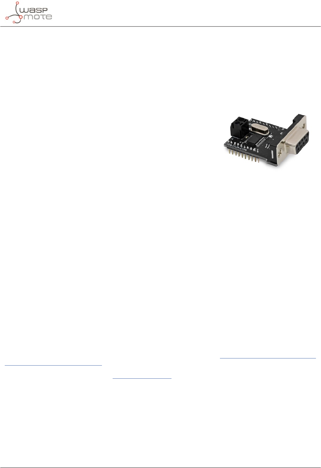
-112- v8.2
Industrial Protocols
21.2. RS-485/Modbus module
Technical details:
•Protocols: RS-485 and Modbus
•Standard: EIA RS-485
•Physical media: Twisted pair
•Connector: DB9
•Network topology: Point-to-point, Multi-dropped, Multi-point
•Maximum devices: 32 drivers or receivers
•Mode of operation: Dierential signaling
•Maximum speed: 460800 bps
•Voltage levels: -7V to +12V
•Mark(1): Positive Voltages (B-A > +200mV)
•Space(0): Negative voltages (B-A < -200mV)
•Available signals: Tx+/Rx+, Tx-/Rx-(Half Duplex)Tx+, Tx-, Rx+, Rx- (Full Duplex)
•Available sockets in Waspmote: socket 0
Applications:
•Industrial Equipment
•Machine to Machine (M2M) communications
•Industrial Control Systems, including the most common versions of Modbus and Probus
•Programmable logic controllers
•RS485 is also used in building automation
•Interconnect security control panels and devices
Related API libraries:
•Wasp485.h, Wasp485.cpp
•ModbusMaster.h, ModbusMaster.cpp
•ModbusSlave.h, ModbusSlave.cpp
All information about their programming and operation can be found in the RS-485 Communication Guide and
the Modbus Communication Guide.
All the documentation is located in the Development section in the Libelium website.
Figure: RS-485/Modbus module
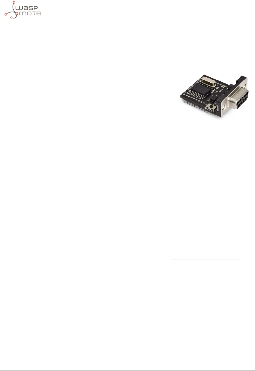
-113- v8.2
Industrial Protocols
21.3. CAN Bus module
Technical details:
•Protocol: CAN Bus
•Standard: ISO 11898
•Cabling: Twisted Pair
•Connector: DB9
•Network topology: Multimaster
•Speed: 125 to 1000 Kbps
•Signaling: dierential
•Voltage levels: 0-5V
•Signals: Half Duplex
•Available sockets in Waspmote: socket 0
Applications:
•Automotive applications
•Home automation
•Industrial Networking
•Factory automation
•Marine electronics
•Medical equipment
•Military uses
Related API libraries:
•WaspCAN.h, WaspCAN.cpp
All information about their programming and operation can be found in the CAN Bus Communication Guide.
All the documentation is located in the Development section in the Libelium website.
Figure: Can Bus module

-114- v8.2
Industrial Protocols
21.4. Modbus
The Modbus is a software library that can be operated physically on the RS-485 modules. Thus, Modbus is a
software layer which provides with interesting services.
Technical details:
•Protocol: Modbus
•Data area: Up to 255 bytes per job
•Interface: Layer 7 of the ISO-OSI reference model
•Connector: DB9 (RS-485 module)
•Number of possible connections: up to 32 in multi point systems
•Frame format: RTU
Applications:
•Multiple master-slave applications
•Sensors and Instruments
•Industrial Networking
•Building and infrastructure
•Transportation and energy applications
Related API libraries:
•Wasp485.h, Wasp485.cpp
•ModbusMaster.h, ModbusMaster.cpp
•ModbusSlave.h, ModbusSlave.cpp
All information about their programming and operation can be found in the RS-485 Communication Guide and
Modbus Communication Guide.
All the documentation is located in the Development section in the Libelium website.
Figure: RS-485 module
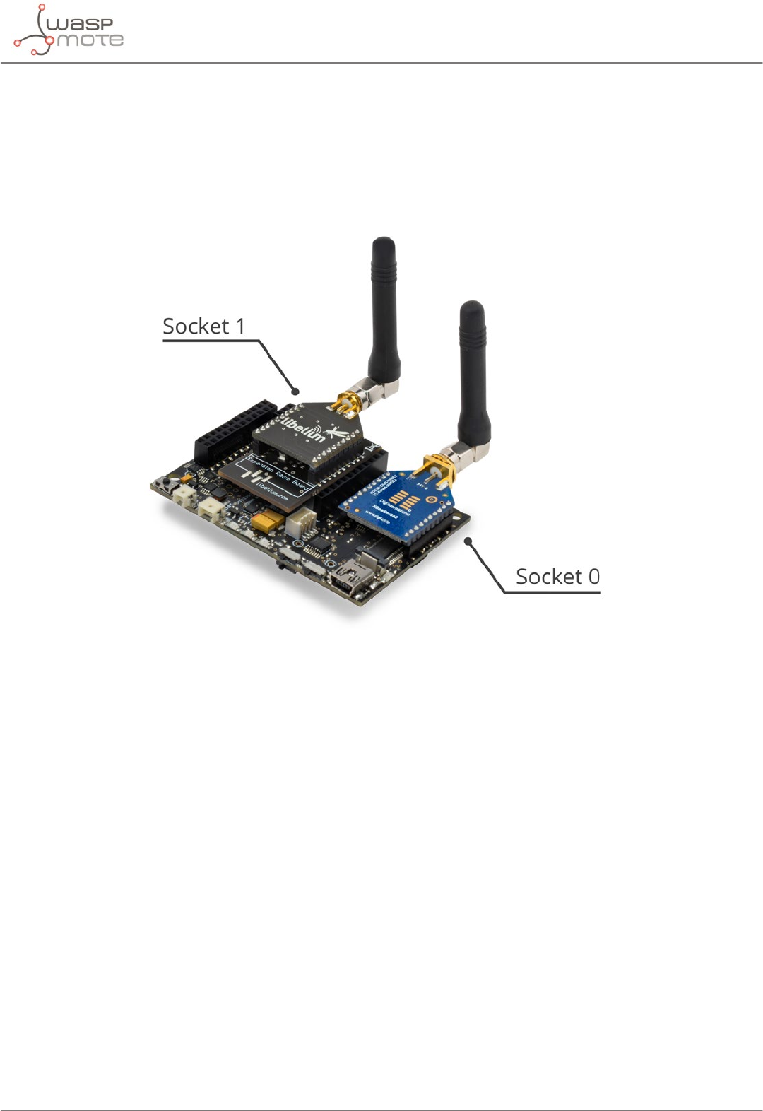
-115- v8.2
Expansion Radio Board
22. Expansion Radio Board
The Expansion Board allows to connect two communication modules at the same time in the Waspmote sensor
platform. This means a lot of dierent combinations are possible using any of the wireless radios available for
Waspmote: 802.15.4, ZigBee, DigiMesh, 868 MHz, 900 MHz, LoRa, WiFi, GPRS, 3G, NB-IoT / Cat-M, 4G, Sigfox,
LoRaWAN, Bluetooth Pro, Bluetooth Low Energy and RFID/NFC. Besides, the following Industrial Protocols modules
are available: RS-485/Modbus and CAN Bus.
Figure: Expansion Radio Board
Some of the possible combinations are:
•LoRaWAN - GPRS
•802.15.4 - Sigfox
•868 MHz - RS-485
•NB-IoT / Cat-M - WiFi
•DigiMesh - 4G
•NB-IoT / Cat-M - RFID/NFC
•WiFi - 3G
•CAN Bus - Bluetooth
•etc.
Remark: GPRS, 3G, NB-IoT / Cat-M and 4G modules do not need the Expansion Board to be connected to Waspmote.
They can be plugged directly in the socket1.
Applications:
•Multifrequency Sensor Networks (2.4 GHz – 868/900 MHz)
•Bluetooth - ZigBee hybrid networks
•NFC (RFID) applications with 3G/GPRS
•ZigBee - WiFi hybrid networks
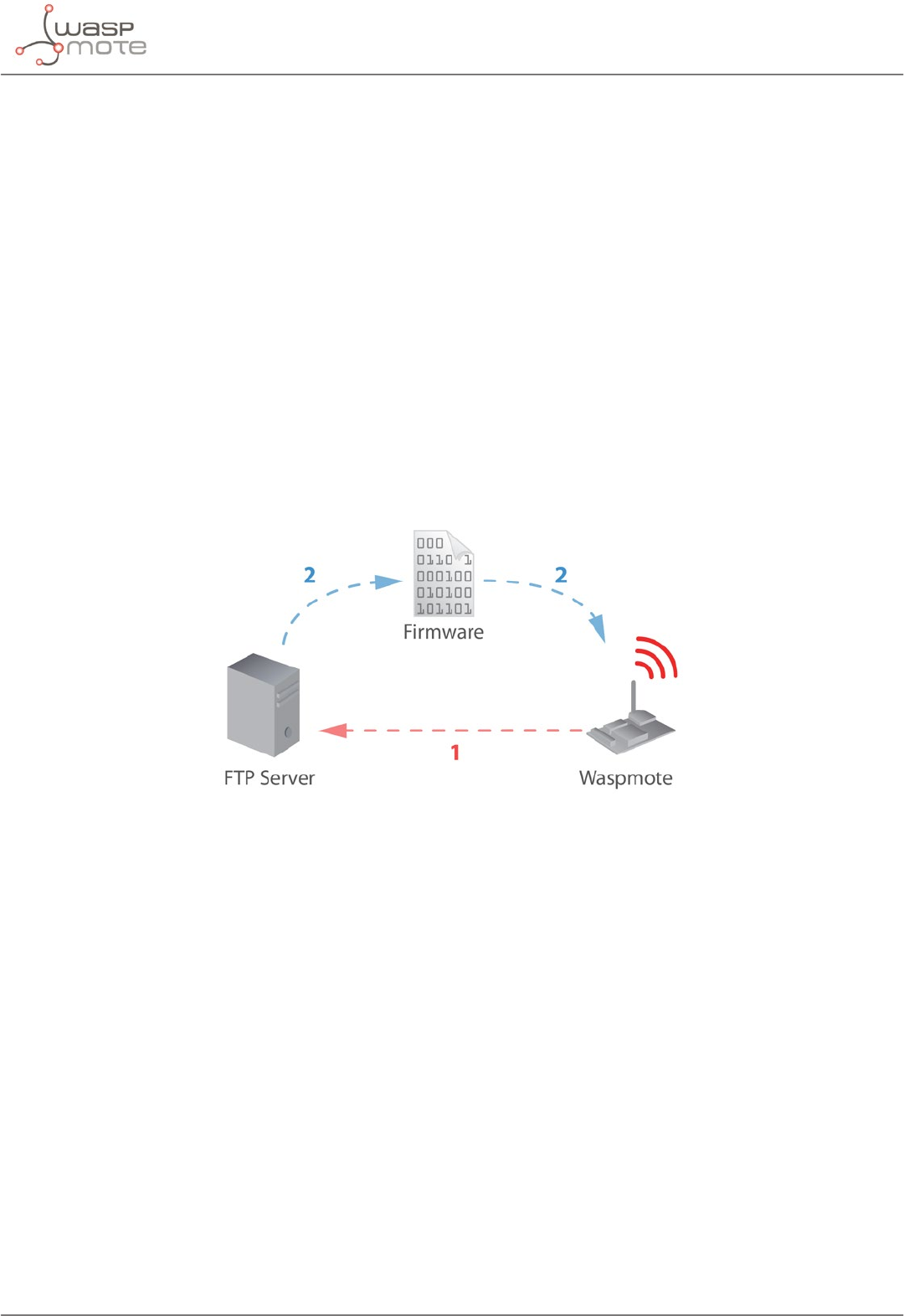
-116- v8.2
Over the Air Programming (OTA)
23. Over the Air Programming (OTA)
23.1. Overview
The concept of Wireless Programming or commonly known as Programming Over the Air (OTA) has been used
in the past years overall for the reprogramming of mobile devices such as cell phones. However, with the new
concepts of Wireless Sensor Networks and the Internet of Things where the networks consist of hundreds or
thousands of nodes OTA is taken to a new direction.
Libelium provides an OTA method based on FTP transmissions to be used with GPRS, 3G, 4G and WiFi modules.
23.2. OTA with 4G/GPRS/WiFi modules via FTP
It is possible to update the Waspmote’s program using Over The Air Programming and the following modules:
4G/3G, GPRS or WiFi module.
The Waspmote reprogramming is done using an FTP server and an FTP client (which is Waspmote itself). The FTP
server can be congured by Meshlium. Otherwise, the user will have to setup an FTP server.
Figure: OTA via FTP protocol
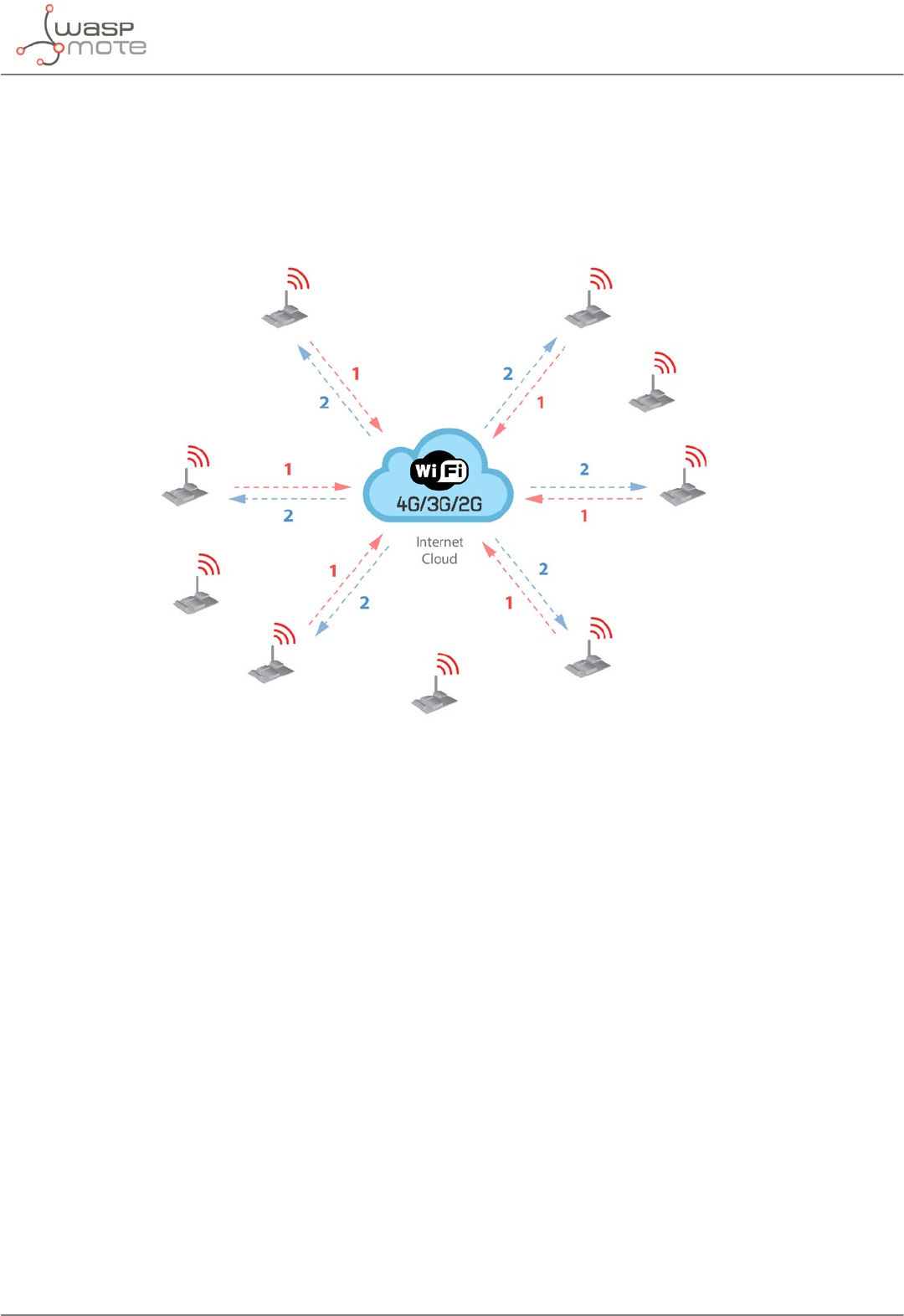
-117- v8.2
Over the Air Programming (OTA)
There are 2 basic steps involved in OTA procedure:
•Step 1: Waspmote requests a special text le which gives information about the program to update: pro-
gram name, version, size, etc.
•Step 2: If the information given is correct, Waspmote queries the FTP server for a new program binary le
and it updates its ash memory in order to run the new program.
Figure: OTA steps via FTP protocol
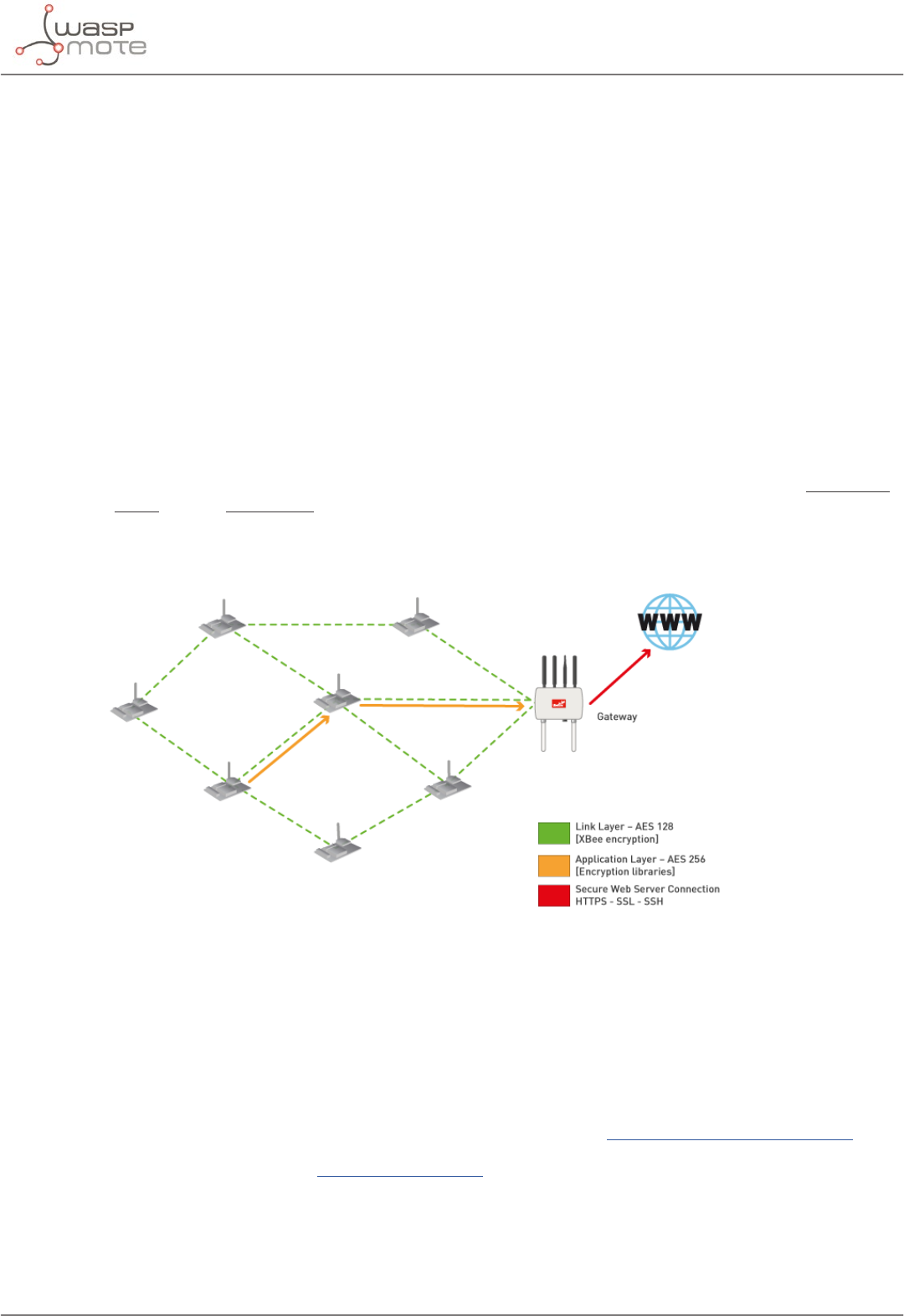
-118- v8.2
Encryption libraries
24. Encryption libraries
The Encryption Libraries are designed to add to the Waspmote sensor platform the capabilities necessary to
protect the information gathered by the sensors. To do so, 2 cryptography layers are dened:
•Link Layer: In the rst one all the nodes of the network share a common preshared key which is used to en-
crypt the information using AES 128. This process is carried out by specic hardware integrated in the same
802.15.4/ZigBee radio, allowing the maximum eciency of the sensor nodes energy consumption. This rst
security layer ensures no third party devices will be able to even connect to the network (access control).
•Secure Web Server Connection: The second security technique is carried out in Meshlium -the Gateway-
where HTTPS and SSH connections are used to send the information to the Cloud server located on the
Internet.
A third optional encryption layer allows each node to encrypt the information using the Public key of the Cloud
server. Thus, the information will be kept condentially all the way from the sensor device to the web or data base
server on the Internet.
Transmission of sensor data:
Information is encrypted in the application layer via software with AES 256 using the key shared exclusively
between the origin and the destination. Then the packet is encrypted again in the link layer via hardware with AES
128 so that only trusted packets be forwarded, ensuring access control and improving the usage of resources of
the network.
Figure: Communication diagram
Related API libraries:
•WaspAES.h, WaspAES.cpp
•WaspRSA.h, WaspRSA.cpp
•WaspHash.h, WaspHash.cpp
All information about their programming and operation can be found in the Encryption Programming Guide.
All the documentation is located in the Development section in the Libelium website.
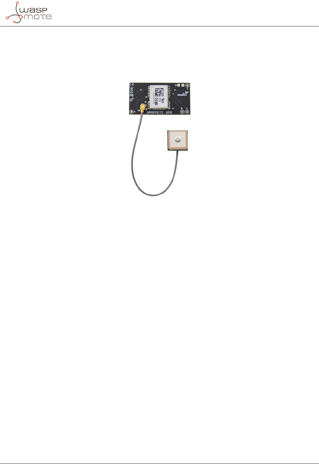
-119- v8.2
GPS
25. GPS
Waspmote can integrate a GPS receiver which allows to know the exact location of the mote anytime. Thus, the
exact position of the mote can be obtained and even the current time and date, to synchronize the Waspmote
internal clock (RTC) with the real time. Besides, data can be geolocated on a map.
Figure: GPS module
The GPS module gives us information about:
•latitude
•longitude
•altitude
•speed
•direction
•date/time
•ephemeris
The functions implemented in the API allow this information to be extracted simply, calling functions such as:
{
GPS.getAltitude();
GPS.getSpeed();
GPS.getLongitude();
GPS.getLatitude();
}
The GPS receiver uses the UART_1 to communicate with the microcontroller, sharing this UART with the GPRS,
3G, , NB-IoT / Cat-M or 4G modules. As up to 2 modules share this UART, a multiplexer has been enabled in order
to select the module with which we wish to communicate at any time. This is not a problem; since all actions are
sequential, in practice there is parallel availability of both devices.
The GPS starts up by default at 4800 bps. This speed can be increased using the library functions that have been
designed for controlling and managing the module.
The GPS receiver has 2 operational modes: NMEA (National Marine Electronic Association) mode and binary
mode. NMEA mode uses statements from this standard to obtain location, time and date. The binary mode is
based on the sending of structured frames to establish communication between the microcontroller and the GPS
receiver, i.e. to read/set ephemeris.
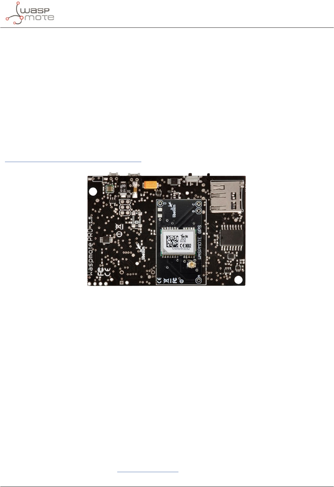
-120- v8.2
GPS
The dierent types of NMEA statements that the Waspmote’s built-in GPS receiver supports are:
•NMEA GGA: provides location data and an indicator of data accuracy
•NMEA GSA: provides the status of the satellites the GPS receiver has been connected to
•NMEA GSV: provides information about the satellites the GPS receiver has been connected to
•NMEA RMC: provides information about the date, time, location and speed
•NMEA VTG: provides information about the speed and course of the GPS receiver
•NMEA GLL: provides information about the location of the GPS receiver
The most important NMEA statements are the GGA statements which provide a validity indicator of the measurement
carried out, the RMC statement which provides location, speed and date/time and the GSA statement which
provides information about the status of the satellites the GPS receiver has been connected to.
(To obtain more information about the NMEA standard and the NMEA statements, visit the website:
http://www.gpsinformation.org/dale/nmea.htm)
Figure: GPS module connected to Waspmote
The GPS receiver needs time to obtain and structure the information that the satellites send. This time can be
reduced if there is certain prior information. This information is stored in the almanacs and ephemeris. The
information that can be found out is relative to the current position of the satellites (ephemeris) and the trajectory
they are going to follow over the next days (almanacs). The almanacs indicate the trajectory that the satellites are
going to follow during the next days, having a validity of some 2-3 months. The ephemeris indicate the current
position of the satellites and have a validity of some 3-5 hours.
Depending on the information that the GPS receiver has, the start ups can be divided into these types:
•Hot start: once the time and date are established and the ephemeris and valid almanacs are in the me-
mory. Time: <1 s.
•Cold start: without having established the time, date, almanacs or ephemeris. Time: <35 s.
As can be observed, the start up time reduces greatly, particularly when ephemeris are stored. For this reason
a series of functions have been created in the libraries to store ephemeris on the SD card and enable them to
be loaded later.
Related API libraries: WaspGPS.h, WaspGPS.cpp.
All information about their programming and operation can be found in the document: GPS Programming Guide.
All the documentation is located in the Development section in the Libelium website.
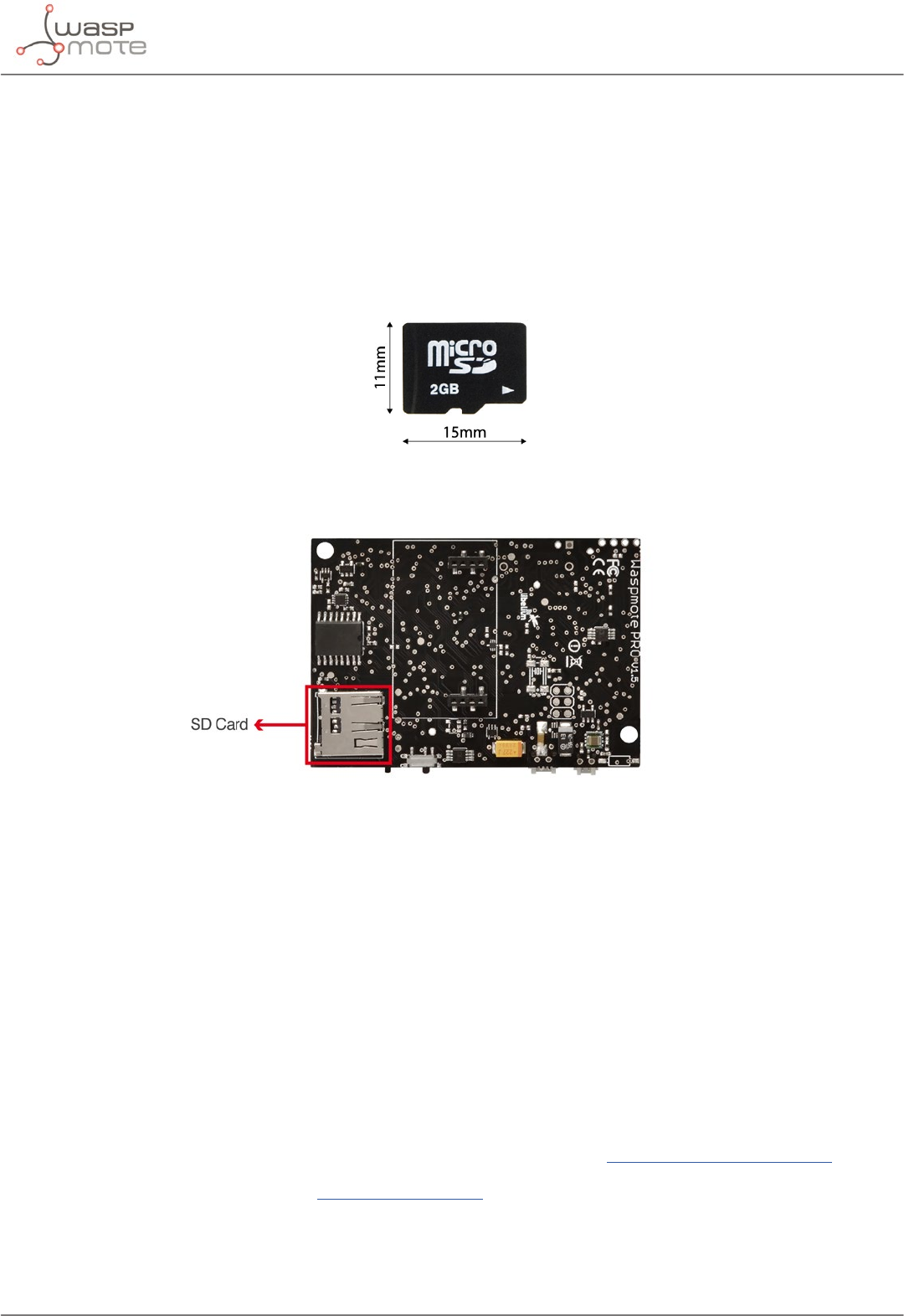
-121- v8.2
SD memory card
26. SD memory card
Waspmote has external storage support such as SD (Secure Digital) cards. These micro-SD cards are used
specically to reduce board space to the minimum.
Note: Until February 2018, 2 GB SD cards were distributed; they operated with FAT16. Since that moment, Libelium
distributes FAT32 micro SD cards (8 GB cards from February; 16 GB cards from June). These cards need the bootloader
#J to work properly.
Micro-SD card
Waspmote uses the FAT32 le system. The information that Waspmote stores in les on the SD can be accessed
from dierent operating systems such as Linux, Windows or Mac-OS.
Figure: SD card slot
To communicate with the SD module we use the SPI bus. This bus is a communication standard used to transfer
information between electronic devices which accept clock regulated bit ow.
The SD card is powered through a digital pin from the microcontroller. It is not therefore necessary to use a
switch to cut the power, putting a low pin value is enough to set the SD consumption to 0 μA.
For example, to get an idea of the capacity of information that can be stored in a 16 GB card, simply divide its size
by the average for what a sensor frame in Waspmote usually occupies (approx. 100 bytes):
16 GB/100 B = 160 million measurements
The limit in les and directories creation per level is 256 les per directory and up to 256 sub-directories in each
directory. There is no limit in the number of nested levels.
Related API libraries: WaspSD.h, WaspSD.cpp
All information about their programming and operation can be found in the SD Card Programming Guide.
All the documentation is located in the Development section in the Libelium website.
Note: Make sure Waspmote is switched o before inserting or removing the SD card. Otherwise, the SD card could be
damaged.

-122- v8.2
Energy Consumption
Note: Waspmote must not be switched o or reseted while there are ongoing read or write operations in the SD card.
Otherwise, the SD card could be damaged and data could be lost.
27. Energy Consumption
27.1. Consumption tables
Waspmote
On 17 mA
Sleep 30 μA
Deep Sleep 33 μA
Hibernate 7 μA
XBee
SENDING RECEIVING
XBee-PRO 802.15.4 250 mA 55 mA
XBee-PRO ZigBee 295 mA 45 mA
XBee 868LP 48 mA 27 mA
XBee-PRO 900HP 215 mA 29 mA
Bluetooth modules
On O Sleep Scanning Sending Receiving
Bluetooth Pro 14 mA 0 mA <0,5 mA 40 mA 34 mA 20 mA
Bluetooth Low
Energy
8 mA 0 mA 0.4 μA 36 mA 36 mA 36 mA
GPS
On (tracking) 32 mA
O (Waspmote switch) 0 μA
GPRS Pro
Connecting ~100 mA
Calling ~100 mA
Receiving calls ~100 mA
Transmitting GPRS ~100 mA
Sleep 1 mA
O ~0 μA

-123- v8.2
Energy Consumption
3G/GPRS
Connecting ~100 mA
Transmitting/Receiving
GPRS
~100 mA (1.2A – 2 A during transmission slot every
4.7ms )
Transmitting/Receiving 3G ~300 mA - 500 mA
Sleep 1 mA
O ~0 μA
SD
On 0.14 mA
Reading 0.2 mA
Writing 0.2 mA
O 0 μA
Accelerometer
Sleep 0,08 mA
Hibernate 0,65 mA
O ~0 μA
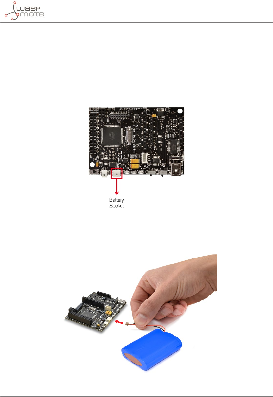
-124- v8.2
Power supplies
28. Power supplies
28.1. Battery
Libelium oers 2 types of battery for the Waspmote OEM line:
•a 6600 mA·h, rechargeable lithium-ion battery (Li-Ion), with 3.7 V nominal voltage
•a 52000 mA·h, non-rechargeable battery, with 3.4 V nominal voltage
Waspmote has a control and safety circuit which makes sure the battery charge current is always adequate.
Figure: Battery connector
Battery connection
The gure below shows the connector in which the battery is to be connected. The position of the battery connector
is unique, therefore it will always be connected correctly (unless the connector is forced).
Figure: Battery connection
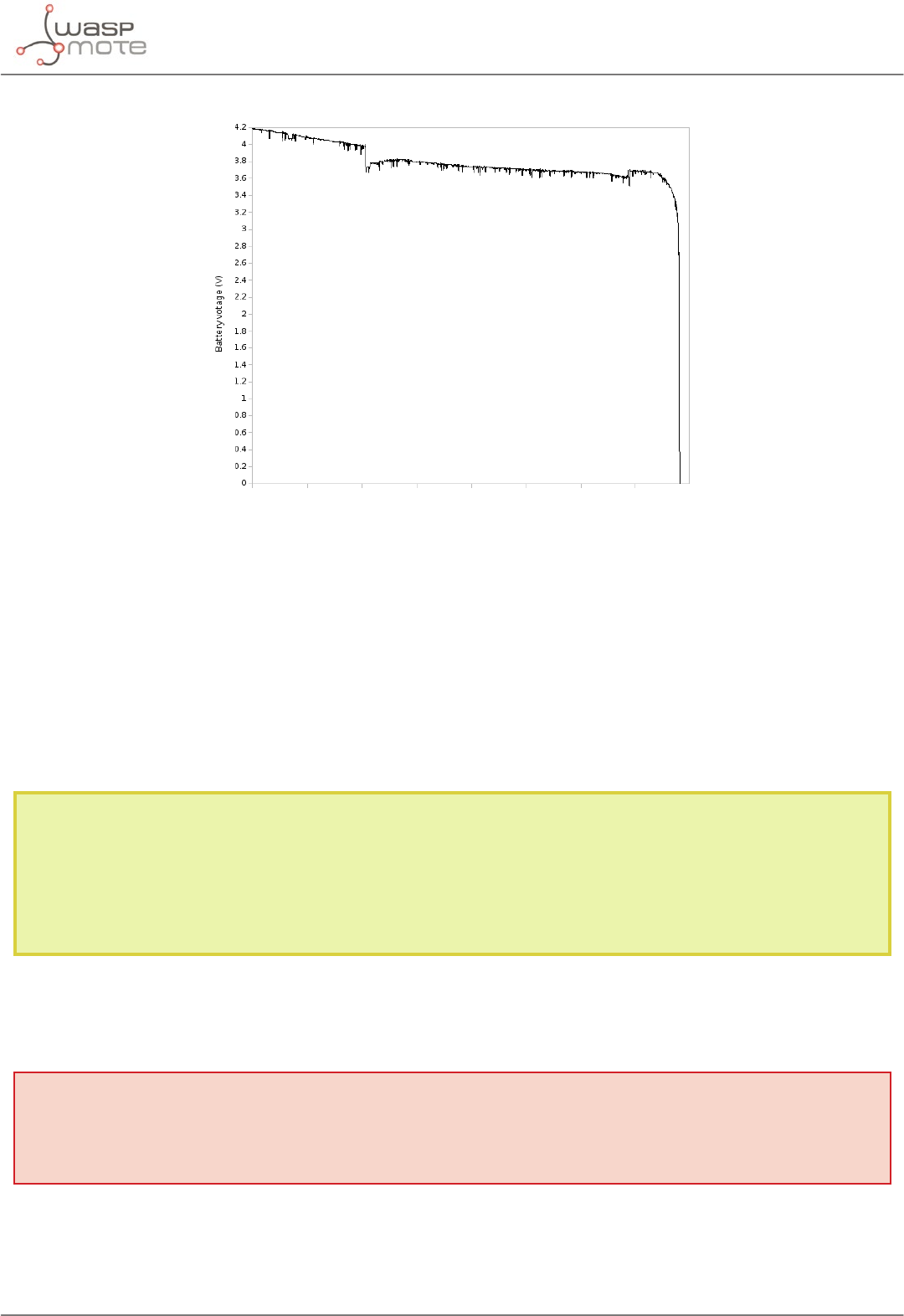
-125- v8.2
Power supplies
Battery discharging
Figure: Typical discharging curve for battery
Characteristics of the equipment used to generate charging curves:
Battery used: 3.7 V - 6600 mA·h battery
As seen above, the rechargeable battery shows a nice slope on its output voltage as its level goes down. Waspmote
monitors this voltage in order to calculate the current battery level. However, a rechargeable battery has a very
plain discharge graph, so it is not possible to know the remaining energy inside it.
Notes about the rechargeable battery:
•When recharging, if the battery is near 0%, it will take some time before the battery level increases.
•It is normal to see some battery level variations during the charging periods due to the Waspmote charging
circuitry. To know the real battery level of the node, it is recommended to measure it when the node is not
being recharged and also with sensors and radio modules switched o.
Warning: Batteries with voltage over 3.7 V could irreparably damage Waspmote.
Incorrect battery connection could irreparably damage Waspmote.
DO NOT TRY TO RECHARGE THE NON-RECHARGEABLE BATTERY, IT MAY EXPLODE AND CAUSE INJURIES
AND DESTROY THE EQUIPMENT. USE NON-RECHARGEABLE BATTERIES ONLY WITH DEVICES PROPERLY
PREPARED. PLEASE DOUBLE CHECK THIS CONDITION BEFORE CONNECTING THE USB OR THE SOLAR
PANEL.
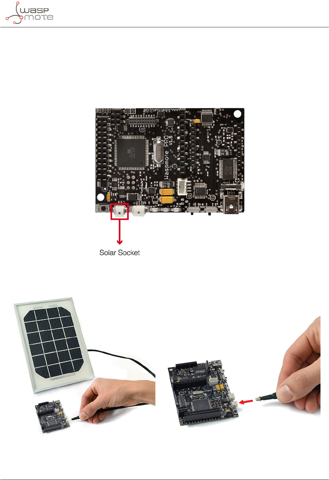
-126- v8.2
Power supplies
28.2. Solar panel
The solar panel must be connected using the cable supplied.
Both the mini USB connector and the solar panel connector allow only one connection position which must be
respected without being forced into the incorrect position. In this way connection polarity is respected.
Solar panels up to 12 V are allowed. The maximum charging current through the solar panel is 300 mA.
Solar panel connector
Figure: Solar panel connection
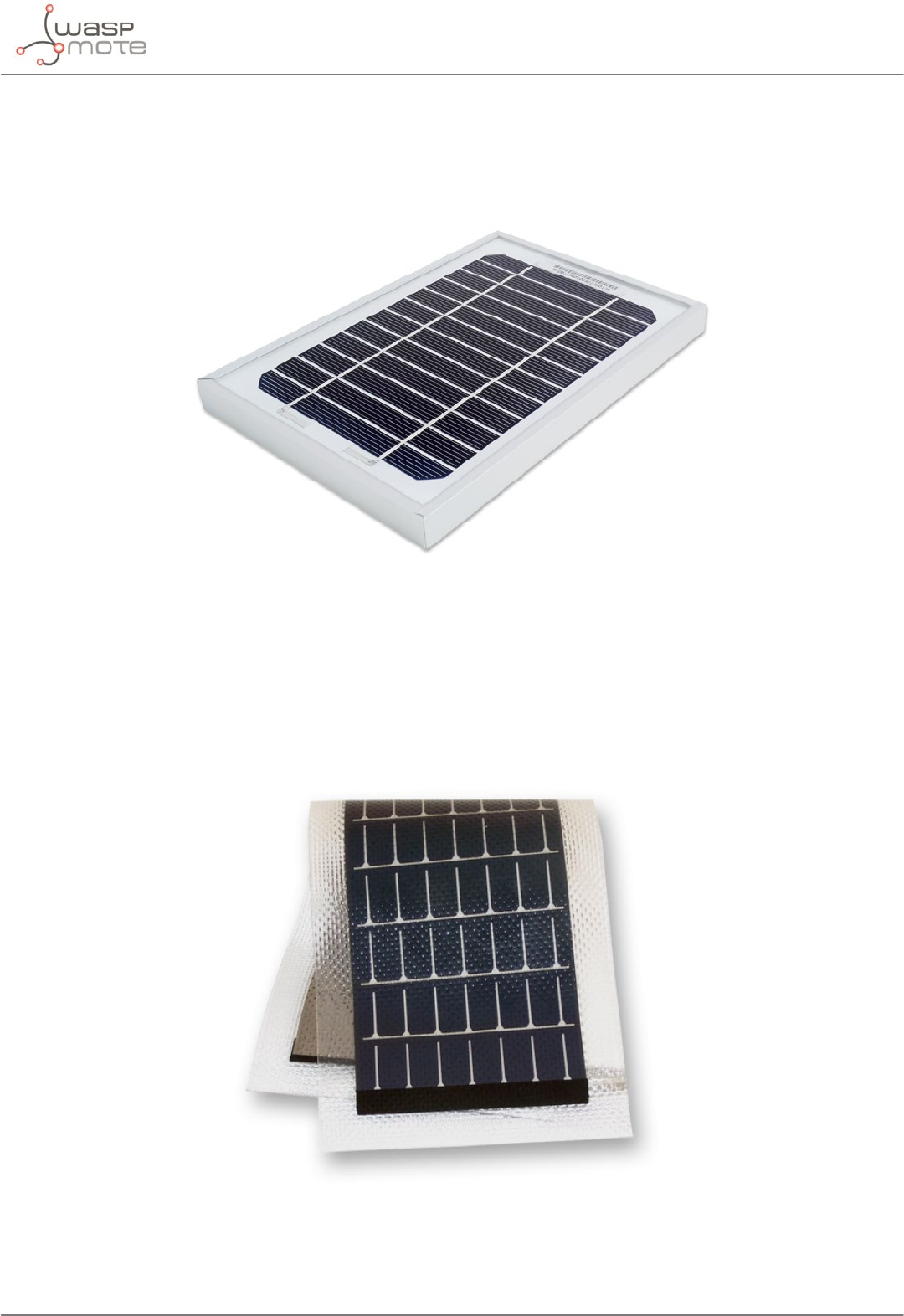
-127- v8.2
Power supplies
The models supplied by Libelium are shown below:
•Rigid solar panel
-7 V - 500 mA
- Dimensions: 234 x 160 x 17 mm
Figure: Rigid solar panel
•Flexible solar panel
-7.2 V - 100 mA
-Dimensions: 284 x 97 x 2 mm
Figure: Flexible solar panel
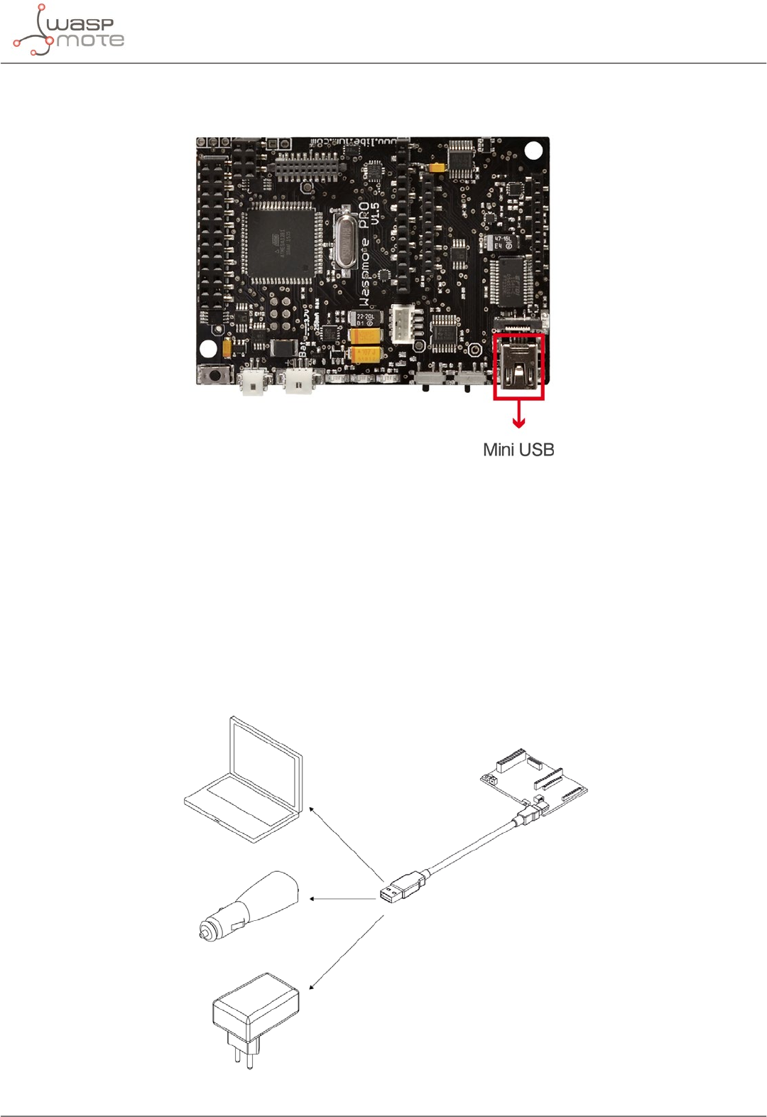
-128- v8.2
Power supplies
28.3. USB
Figure: Mini-USB connector
Waspmote’s USB power sources are:
•USB to PC connection
•USB to 220 V connection
•USB to vehicle connector connection
The charging voltage through the USB has to be 5 V.
The maximum charging current through the USB is 480 mA (100 mA in batches since summer 2018).
The mini USB connector must be standard mini USB model B.
Figure: Possible connections for the USB
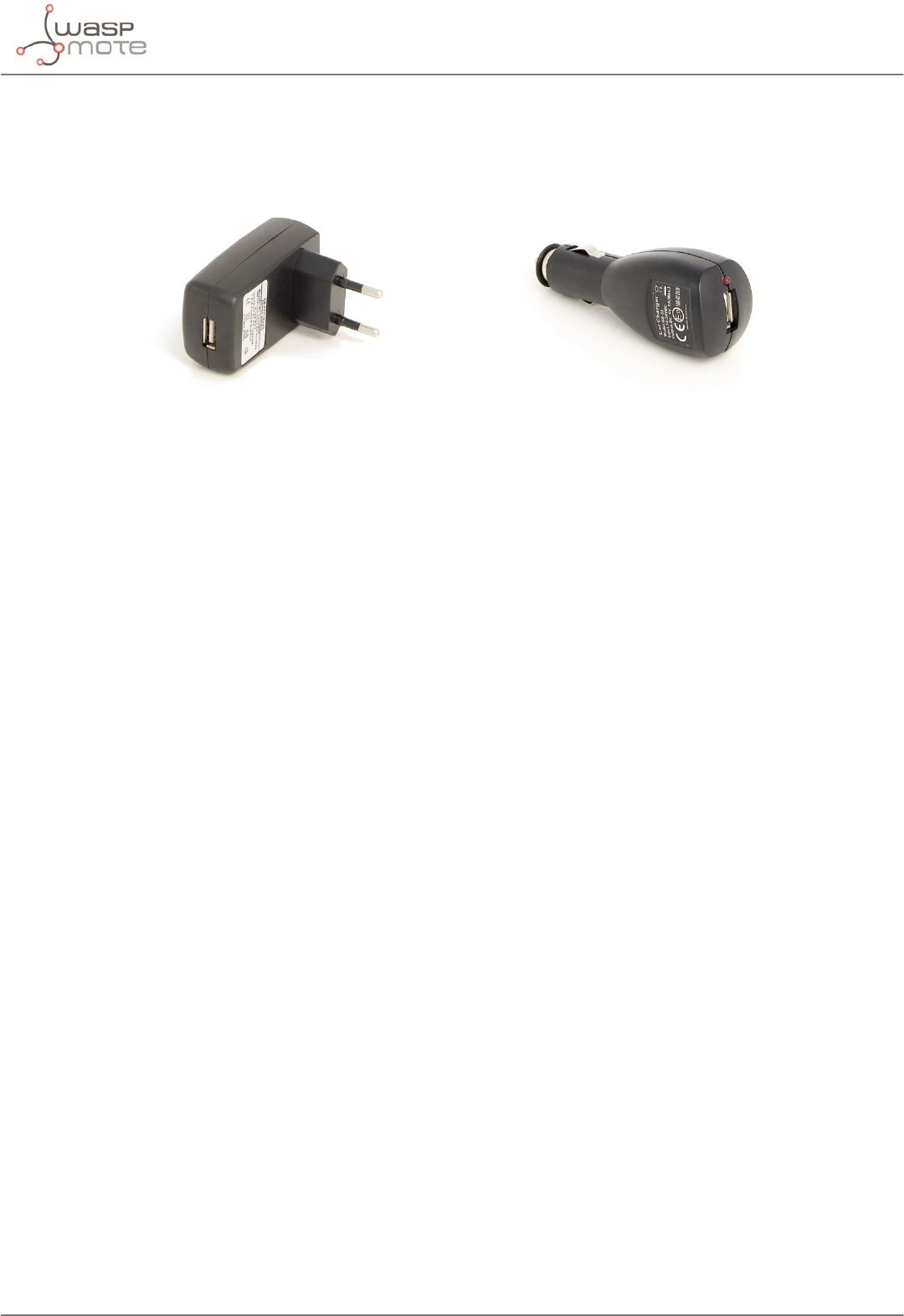
-129- v8.2
Power supplies
The models supplied by Libelium are shown below:
Figure: 220 V AC – USB adapter Figure: 12 V DC – USB car lighter adapter
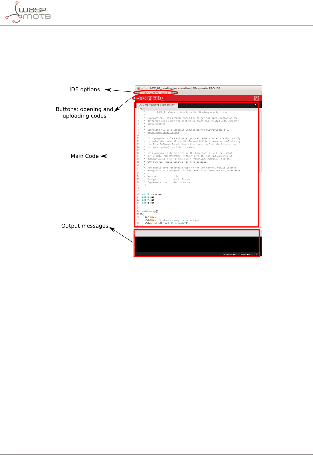
-130- v8.2
Working environment
29. Working environment
The Integrated Development Environment (IDE) is used for writing the code and uploading it to Waspmote and
Plug & Sense!. It is also used to monitor serial output and for debugging. This IDE contains the Waspmote API (the
API is the set of all libraries Waspmote needs for compiling programs). New API versions are released instantly by
Libelium whenever improvements are made or bugs xed.
Figure: Waspmote IDE
All information about the IDE installation and operation can be found in the IDE User Guide.
All the documentation is located in the Development section in the Libelium website.
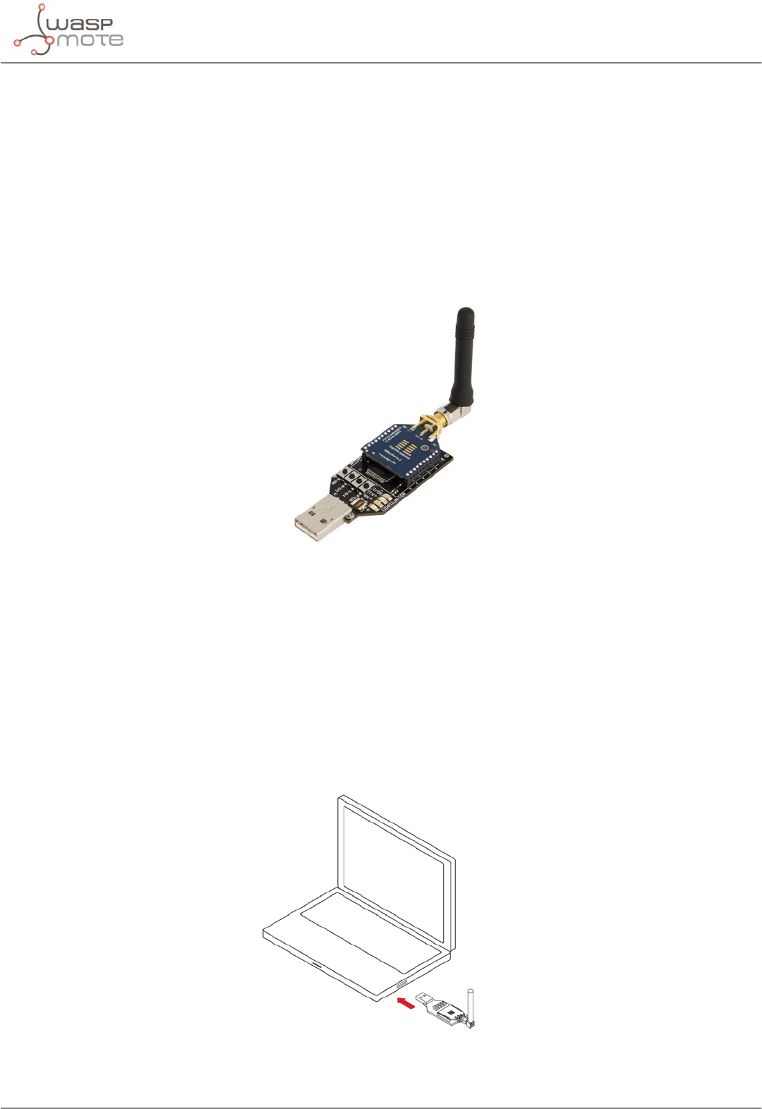
-131- v8.2
Interacting with Waspmote
30. Interacting with Waspmote
30.1. Receiving XBee frames with Waspmote Gateway
30.1.1. Waspmote Gateway
This device allows to collect data which ows through the sensor network into a PC or device with a standard USB
port. Waspmote Gateway will act as a ”data bridge or access point” between the sensor network and the receiving
equipment. This receiving equipment will be responsible for storing and using the data received depending on the
specic needs of the application.
Figure: Waspmote Gateway
The receiving equipment can be a PC with Linux, Windows or Mac-OS, or any device compatible with standard
USB connectivity. The gateway oers a male USB A connector, so the receiving device has to have a female USB
A connector.
Once the Gateway is correctly installed, a new communication serial port connecting directly to the XBee module’s
UART appears in the receiving equipment, which allows the XBee to communicate directly with the device, being
able to both receive data packets from the sensor network as well as modify and/or consult the XBee’s conguration
parameters.
Another important function worth pointing out is the possibility of updating or changing the XBee module’s
rmware.
Figure: Waspmote Gateway connected to a PC
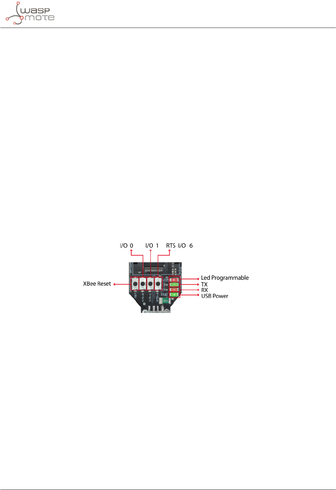
-132- v8.2
Interacting with Waspmote
LEDs
Four indicator LEDs are included in the Gateway:
•USB power LED: indicates that the board is powered through the USB port
•RX LED: indicates that the board is receiving data from the USB port
•TX LED: Indicates that the board is sending data to the USB port
•I/O 5 congurable LED: associate
The congurable LED connected to the XBee’s I/O 5 pin can be congured either as the XBee’s digital output or as
the XBee’s indicator of association to the sensor network.
Buttons
•Reset: allows the XBee module to be reset
•I/O - 0: button connected to the XBee’s I/O pin 0
•I/O -1: button connected to the XBee’s I/O pin 1
•RTS - I/O – 6: button connected to the XBee’s I/O pin 6
All the buttons connect each one of its corresponding data lines with GND with when pressed. None of these have
pull-up resistance so it may be necessary to activate any of the XBee’s internal pull-up resistances depending on
the required use.
Figure: LEDs in Waspmote Gateway
30.1.2. Linux receiver
When using Linux it is possible to use various applications to capture the input from the serial port. Libelium
recommends to use the ‘Cutecom’ application.
Once the application is launched, the speed and the USB where Waspmote has been connected must be congured.
The speed that must be selected is 115200 bps which is the standard speed set up for Waspmote.
The USB where Waspmote has been connected must be added the rst time this application is run, adding USB0,
USB1, etc (up to the USB number of each computer) according to where Waspmote has been connected. For this,
the ‘Device’ window must be modied so that if Waspmote is connected to USB0, this window contains ‘/dev/
ttyUSB0’.
Once these parameters are congured, capture is started by pressing the ‘Open Device’ button.
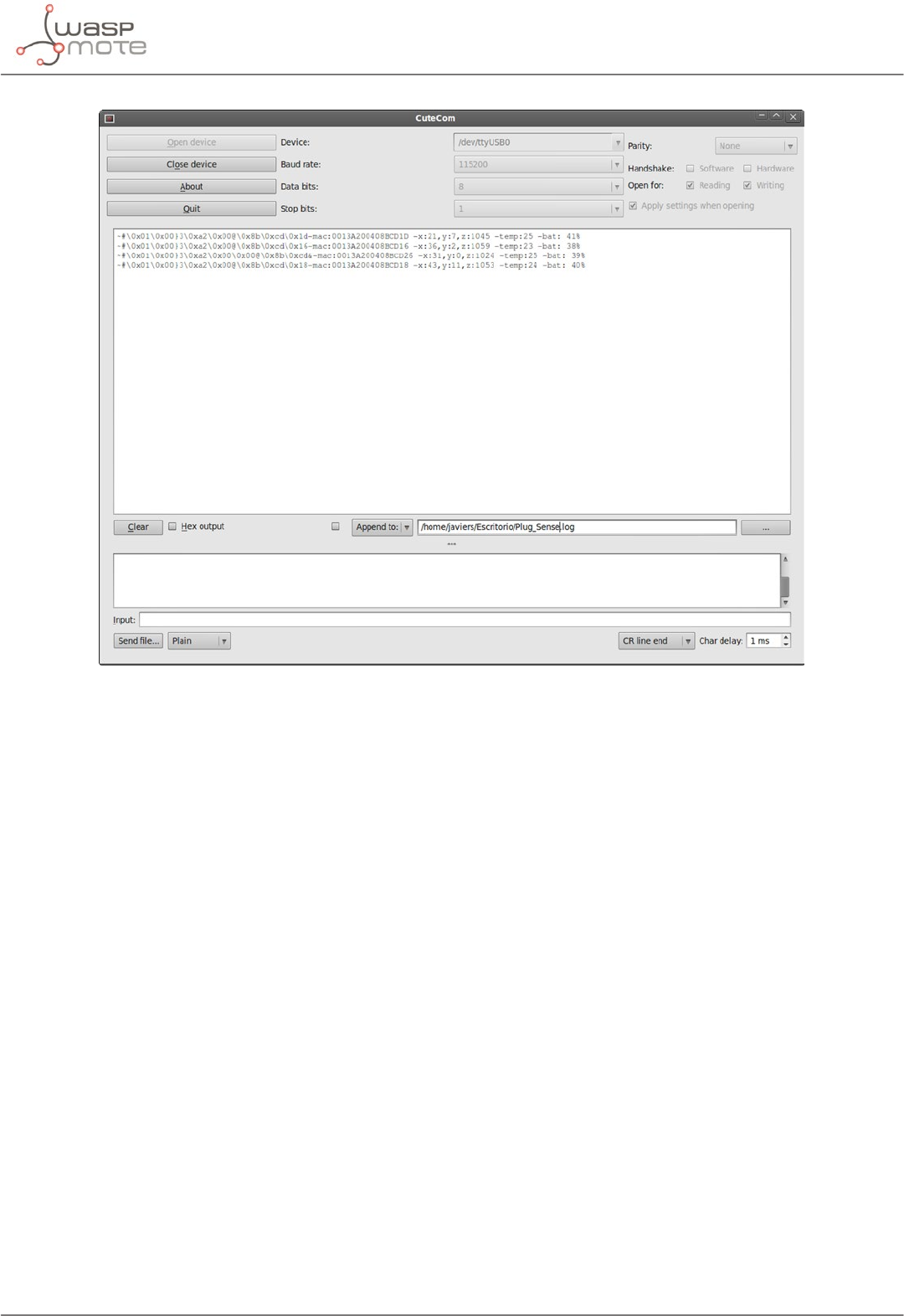
-133- v8.2
Interacting with Waspmote
Figure: Cutecom application capturing Waspmote’s output
Linux Snier
As well as using the terminal to see the sensor information, an application which allows this captured data to be
dumped to a le or passed to another program to be used or checked has been developed.
File:
“snier.c”
Compilation on Linux:
gcc sniffer.c -o sniffer
Examples of use:
-Seeing received data: ./sniffer USB0
-Dumping of received data to a le: ./sniffer USB0 >> data.txt
-Passing received values to another program: ./sniffer USB0 | program
Note: The speed used for the example is 19200 bps. The nal speed will depend on the speed the XBee module has been
congured with (default value 115200).
Code:
#include <stdio.h>
#include <string.h>
#include <unistd.h>
#include <fcntl.h>
#include <errno.h>

-134- v8.2
Interacting with Waspmote
#include <stdlib.h>
#include <termios.h> /* Terminal control library (POSIX) */
#dene MAX 100
main(int argc, char *argv[])
{
int sd=3;
char *serialPort=””;
char *serialPort0 = ”/dev/ttyS0”;
char *serialPort1 = ”/dev/ttyS1”;
char *USBserialPort0 = ”/dev/ttyUSB0”;
char *USBserialPort1 = ”/dev/ttyUSBS1”;
char valor[MAX] = ””;
char c;
char *val;
struct termios opciones;
int num;
char *s0 = ”S0”;
char *s1 = ”S1”;
char *u0 = ”USB0”;
char *u1 = ”USB1”;
if(argc!=2)
{
fprintf(stderr,”Usage: %s [port]\nValid ports: (S0, S1, USB0, USB1)\n”,argv[0], serial-
Port);
exit(0);
}
if (!strcmp(argv[1], s0))
{
fprintf(stderr,”ttyS0 chosen\n...”);
serialPort = serialPort0;
}
if (!strcmp(argv[1], s1))
{
fprintf(stderr,”ttyS1 chosen\n...”);
serialPort = serialPort1;
}
if (!strcmp(argv[1], u0))
{
fprintf(stderr,”ttyUSB0 chosen\n...”);
serialPort = USBserialPort0;
}
if (!strcmp(argv[1], u1))
{
fprintf(stderr,”ttyUSB1 chosen\n...”);
serialPort=USBserialPort1;
}
if (!strcmp(serialPort, ””))
{
fprintf(stderr, ”Choose a valid port (S0, S1, USB0, USB1)\n”, serialPort);
exit(0);
}
if ((sd = open(serialPort, O_RDWR | O_NOCTTY | O_NDELAY)) == -1)
{
fprintf(stderr,”Unable to open the serial port %s - \n”, serialPort);
exit(-1);
}

-135- v8.2
Interacting with Waspmote
else
{
if (!sd)
{
sd = open(serialPort, O_RDWR | O_NOCTTY | O_NDELAY);
}
//fprintf(stderr,”Serial Port open at: %i\n”, sd);
fcntl(sd, F_SETFL, 0);
}
tcgetattr(sd, &opciones);
cfsetispeed(&opciones, B19200);
cfsetospeed(&opciones, B19200);
opciones.c_cag |= (CLOCAL | CREAD);
/*No parity*/
opciones.c_cag &= ~PARENB;
opciones.c_cag &= ~CSTOPB;
opciones.c_cag &= ~CSIZE;
opciones.c_cag |= CS8;
/*raw input:
* making the applycation ready to receive*/
opciones.c_lag &= ~(ICANON | ECHO | ECHOE | ISIG);
/*Ignore parity errors*/
opciones.c_iag |= ~(INPCK | ISTRIP | PARMRK);
opciones.c_iag |= IGNPAR;
opciones.c_iag &= ~(IXON | IXOFF | IXANY | IGNCR | IGNBRK);
opciones.c_iag |= BRKINT;
/*raw output
* making the applycation ready to transmit*/
opciones.c_oag &= ~OPOST;
/*aply*/
tcsetattr(sd, TCSANOW, &opciones);
int j = 0;
while(1)
{
read(sd, &c, 1);
valor[j] = c;
j++;
// We start lling the string until the end of line char arrives
// or we reach the end of the string. Then we write it on the screen.
if ((c==’\n’) || (j==(MAX-1)))
{
int x;
for (x=0; x<j; x++)
{
write(2, &valor[x], 1);
valor[x] = ’\0’;
}
j = 0;
}
}
close(sd);
}
The code can be downloaded from: http://www.libelium.com/development/waspmote
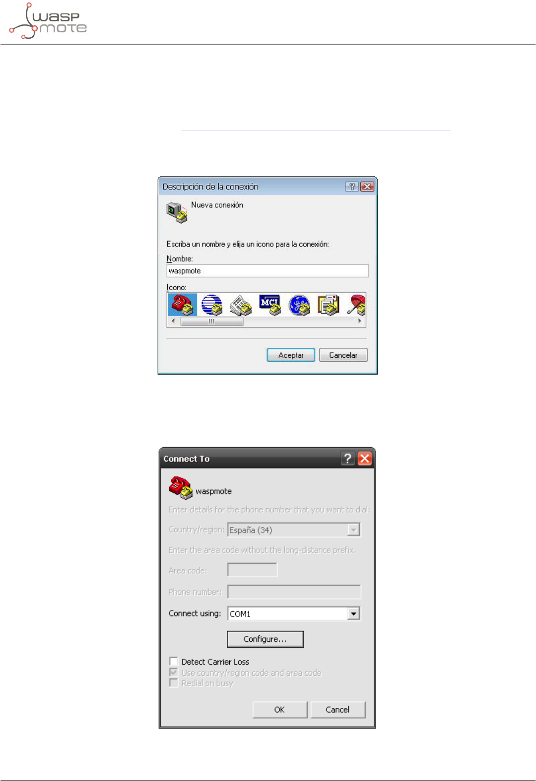
-136- v8.2
Interacting with Waspmote
30.1.3. Windows receiver
If Windows is used, the application ‘Hyperterminal’ can be used to capture the output of the serial port.
This application can be found installed by default in ‘Start/Programs/Accessories/Communication’, but if it is not
available it can be downloaded from: http://hyperterminal-private-edition-htpe.en.softonic.com/
Once this application is launched the connection must be congured. The rst step is to give it a name:
Figure: Step 1 of establishing connection
The next step is to specify the port on which Waspmote has been connected, in this case the system recognizes it
as ‘COM9’, (this will vary on each computer):
Figure: Step 2 of establishing connection
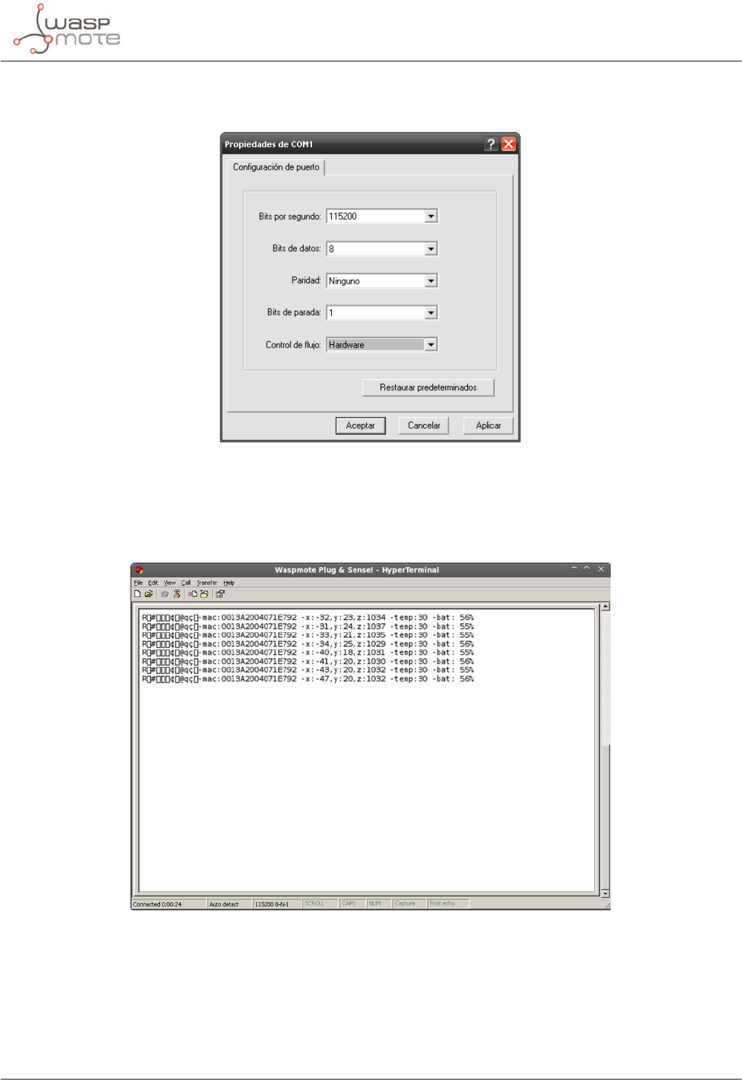
-137- v8.2
Interacting with Waspmote
The next step is to specify the speed and conguration parameters:
Figure: Step 3 of establishing connection
Once these steps have been performed connection with Waspmote has been established, and listening to the serial
port begins.
Figure: HyperTerminal application capturing Waspmote’s output.
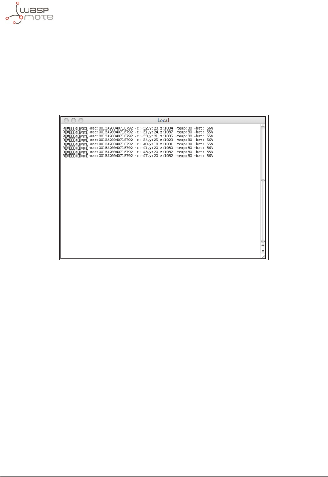
-138- v8.2
Interacting with Waspmote
30.1.4. Mac-OS receiver
If Mac OS X is used (version later than 10.3.9) the application ‘ZTERM’ can be used to capture the serial port output.
This application can be downloaded from: http://homepage.mac.com/dalverson/zterm/
This application is congured automatically, establishing the USB on which Waspmote has been connected and
the speed.
The following image shows this application capturing Waspmote’s output, while the example code ‘Waspmote
Accelerator Basic Example’ is run.
Figure: Waspmote’s output capture
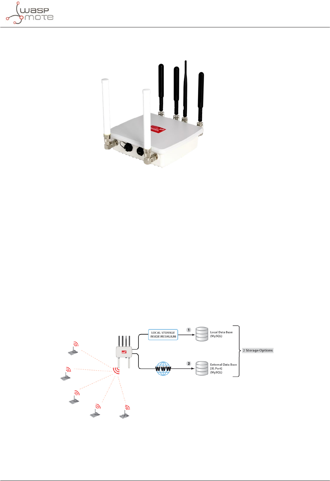
-139- v8.2
Meshlium - The IoT Gateway
31. Meshlium - The IoT Gateway
Figure: Meshlium device
The sensor data gathered by the Waspmote Plug & Sense! nodes is sent to the Cloud by Meshlium, the IoT gateway
router specially designed to connect Waspmote sensor networks to the Internet via Ethernet and 4G/3G/2G
interfaces.
Meshlium can work as:
•an RF (XBee) to Ethernet router for Waspmote nodes*
•an RF (XBee) to 4G/3G/GPRS/GSM router for Waspmote nodes*
•a WiFi Access Point
•a WiFi to 4G/3G/GPRS/GSM router
•a GPS – 4G/3G/GPRS/GSM real-time tracker
•a smartphone scanner (detects iPhone and Android devices)
31.1. Meshlium Storage Options
Figure: Meshlium storage options
•Local data base
•External data base
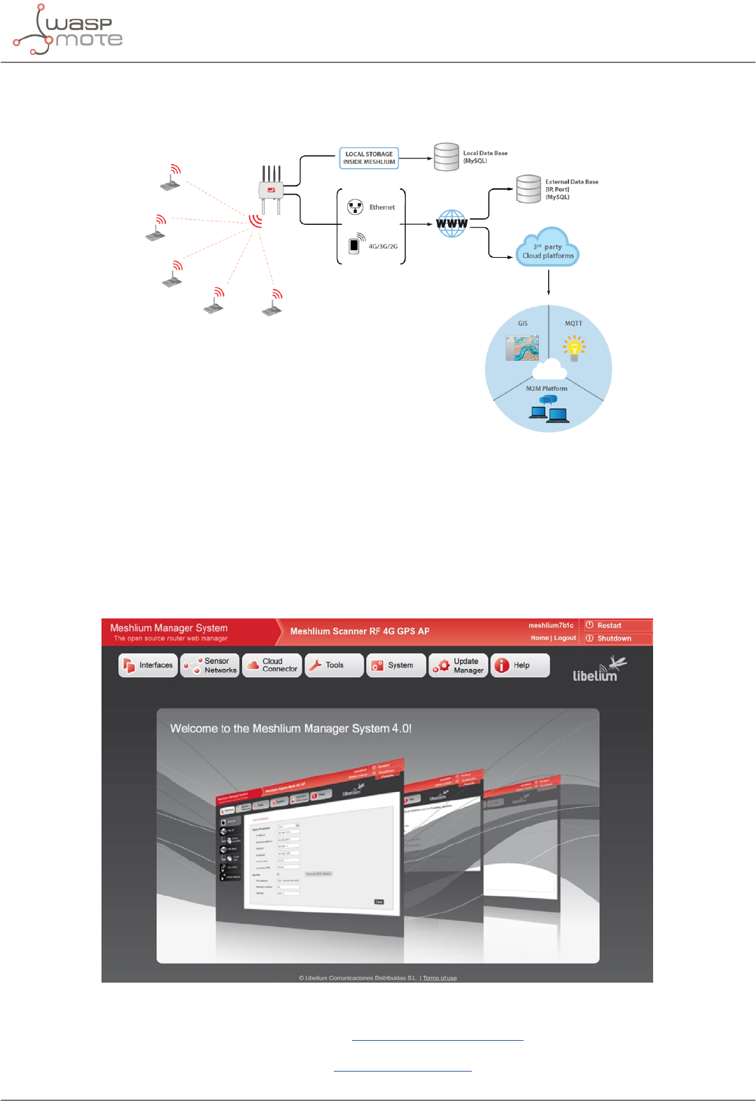
-140- v8.2
Meshlium - The IoT Gateway
31.2. Meshlium connection options
Figure: Meshlium connection options
•XBee / 4G / 3G / 2G / WiFi → Ethernet
•XBee / 4G / 3G / 2G / WiFi → 4G / 3G / 2G
All the networking options can be controlled from the Manager System, a web interface which comes with
Meshlium. It allows to control all the interfaces and system options in a secure, easy and quick way.
Figure: Meshlium Manager System
All information about Meshlium can be found in the Meshlium Technical Guide.
All the Meshlium documentation is located in the Development section in the Libelium website.
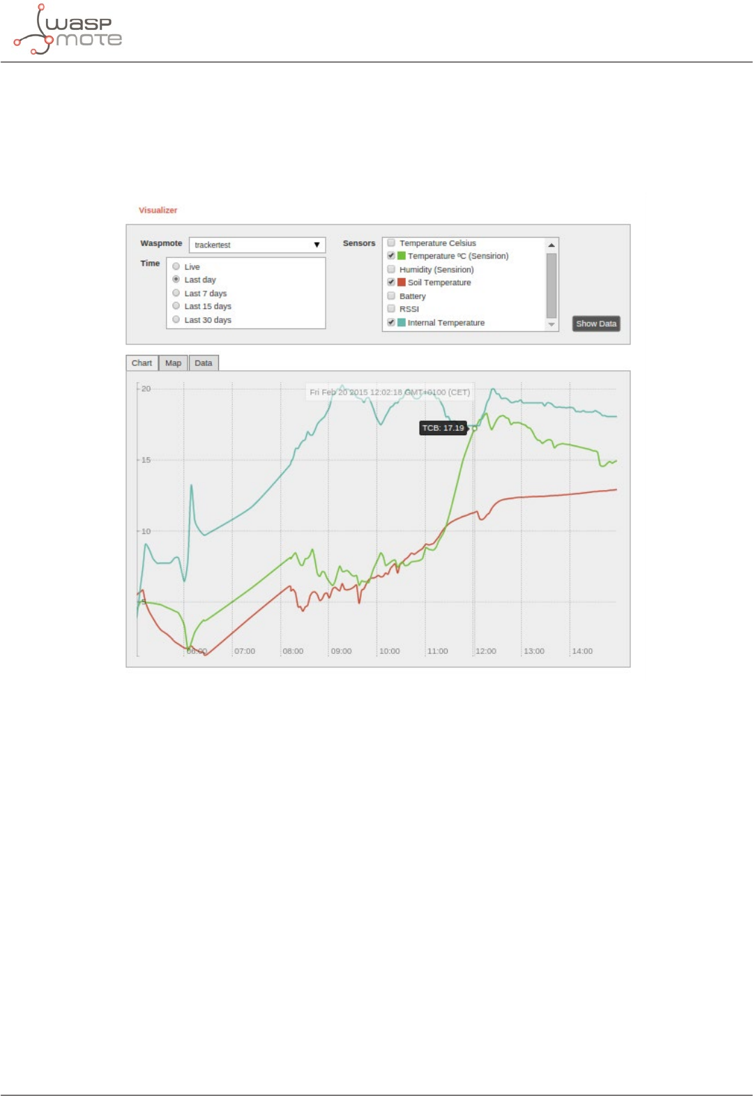
-141- v8.2
Meshlium - The IoT Gateway
31.3. Meshlium Visualizer
Meshlium Visualizer is a plugin which plots graphs and maps with the data stored in the database. It can also
export data in common formats. Meshlium Visualizer is a special software feature only available in the Meshlium
units included in the IoT Vertical Kits (Smart Cities IoT Vertical Kit, Smart Water IoT Vertical Kit, etc).
Figure: Meshlium visualizer

-142- v8.2
Meshlium - The IoT Gateway
31.4. Cloud Connectors
Meshlium allows developers to connect easily with third party cloud servers such as Amazon, IBM, Telefónica, ESRI,
Thingworks, etc. Just select the desired plugin in the Manager System and add the account info to synchronize the
internal data base of Meshlium with the desired platform.
For more info about Meshlium go to:
http://www.libelium.com/products/meshlium/
-143- v8.2
Certications
32. Certications
Libelium oers 2 types of IoT sensor platforms, Waspmote OEM and Plug & Sense!:
•Waspmote OEM is intended to be used for research purposes or as part of a major product so it needs nal
certication on the client side. More info at: www.libelium.com/products/waspmote
•Plug & Sense! is the line ready to be used out-of-the-box. It includes market certications. See below the
specic list of regulations passed. More info at: www.libelium.com/products/plug-sense
Besides, Meshlium, our multiprotocol router for the IoT, is also certied with the certications below. Get more
info at:
www.libelium.com/products/meshlium
List of certications for Plug & Sense! and Meshlium:
•CE (Europe)
•FCC (US)
•IC (Canada)
•ANATEL (Brazil)
•RCM (Australia)
•PTCRB (cellular certication for the US)
•AT&T (cellular certication for the US)
Figure: Certifications of the Plug & Sense! product line
You can nd all the certication documents at:
www.libelium.com/certications

-144- v8.2
Maintenance
33. Maintenance
•In this section, the term “Waspmote” encompasses both the Waspmote device itself as well as its modules
and sensor boards.
•Take care when handling Waspmote, do not let it fall, knock it or move it suddenly.
•Avoid having the devices in high temperature areas as it could damage the electronic components.
•The antennas should be connected carefully. Do not force them when tting them as the connectors could
be damaged.
•Do not use any type of paint on the device, it could harm the operation of the connections and closing me-
chanisms.

-145- v8.2
Disposal and recycling
34. Disposal and recycling
•In this section, the term “Waspmote” encompasses both the Waspmote device itself as well as its modules
and sensor boards.
•When Waspmote reaches the end of its useful life, it must be taken to an electronic equipment recycling
point.
•The equipment must be disposed of in a selective waste collection system, and not that for urban solid re-
sidue. Please manage its disposal properly.
•Your distributor will inform you about the most appropriate and environmentally friendly disposal process
for the used product and its packaging.

-146- v8.2
Documentation changelog
35. Documentation changelog
From v8.1 to v8.2
•Added references to the new NB-IoT / Cat-M module
•Added information about the new Hive service
•Deleted references to the discontinued RS-232 module
•Deleted references to the discontinued Calcium (Ca2+) sensor for Smart Water Ions Single
From v8.0 to v8.1
•Added information about the new Smart Water Xtreme line for Plug & Sense!
•Changed Meshlium images due to new enclosure
From v7.9 to v8.0
•Added references to new LoRaWAN ASIA-PAC / LATAM module
•Deleted references to the discontinued Video Camera Sensor Board
From v7.8 to v7.9
•Updated maximum USB port charging current
From v7.7 to v7.8
•Deleted references to the discontinued Gases Sensor Board
From v7.6 to v7.7
•Added information about the new Smart Agriculture Xtreme line for Plug & Sense!
•Added references to new LoRaWAN IN module
•Changed specications of the SD card, now 16 GB
From v7.5 to v7.6
•Added references to new Sigfox AU / APAC / LATAM module
•Added references to new LoRaWAN AU module
•Deleted references to the discontinued GPRS+GPS radio
From v7.4 to v7.5
•Changed specications of the SD card, now 8 GB
•Changed description of the new External SIM/USB Socket version for Plug & Sense!, now nano-SIM compliant
•Deleted references to the discontinued Internal Solar Panel in Plug & Sense!
From v7.3 to v7.4
•Added references to the Programming Cloud Service for Plug & Sense!
From v7.2 to v7.3
•Added references to the External Battery Module for Plug & Sense!

-147- v8.2
Documentation changelog
•The operating temperature range and maximum recharging current were updated
•Added notes about batteries
From v7.1 to v7.2:
•Added references to the GPS module
•Gases PRO sensors information was upgraded
•Added references to the discontinuation of Smart Environment
•Deleted references to the 13 and 26 A·h non-rechargeable batteries
•Warning about the use of non-rechargeable batteries was modied
From v7.0 to v7.1:
•Added references to the integration of Industrial Protocols for Plug & Sense!
