Microsoft PUC WSI 2007_Flexible_Pipe_Extension_Course PT7000 Wellstream
User Manual: PT7000
Open the PDF directly: View PDF ![]() .
.
Page Count: 67
- Course on Flexible Pipes
- Introduction to Unbonded Flexible PipeDesign & Manufacturing
- Course Outline
- 1.What are Flexible Pipes Used For? What is a Flexible Pipe?
- 2.Flexible Pipes Layer Function and Materials
- 3.Flexible Pipes Design
- 4.Flexible Pipes Layers Raw Material Qualification
- 5.Flexible Pipes Layers Manufacturing Process & Pipe Completion & FAT & Load Out
- 6.Flexible Pipes Prototype Tests

© Wellstream International Limited. Duplication in full or in part is prohibited.
Manufacture -1
USP
Course on Flexible Pipes
Introduction to Unbonded Flexible Pipe
Design & Manufacturing
Judimar Clevelario
Technology Manager
Wellstream do Brasil
© Wellstream International Limited. Duplication in full or in part is prohibited.
Manufacture -2
Course Outline
1.What are Flexible Pipes Used For? What is a Flexible Pipe?
I. Flexible Pipe Layers & Construction
II. Key Design Considerations
III. Main Ancillaries
IV. Main Flexible Pipe Standards and Documentation
2.Flexible Pipes Layer Function and Materials
3.Flexible Pipes Design
I. Design Verification Flowcharts (*)
II. Preliminary Design, Fluid Compatibility & Collapse & Local Stress
III. Global FEA analysis
IV. Bird Cage Local Analysis
V. Bending Stiffener and Pipe Fatigue Local Analysis
VI. Pipe and End Fitting Final Local Analysis
4.Flexible Pipes Layers Raw Material Qualification
5.Flexible Pipes Layers Manufacturing Process & Pipe Completion & FAT & Load Out
6.Flexible Pipes Prototype Tests
© Wellstream International Limited. Duplication in full or in part is prohibited.
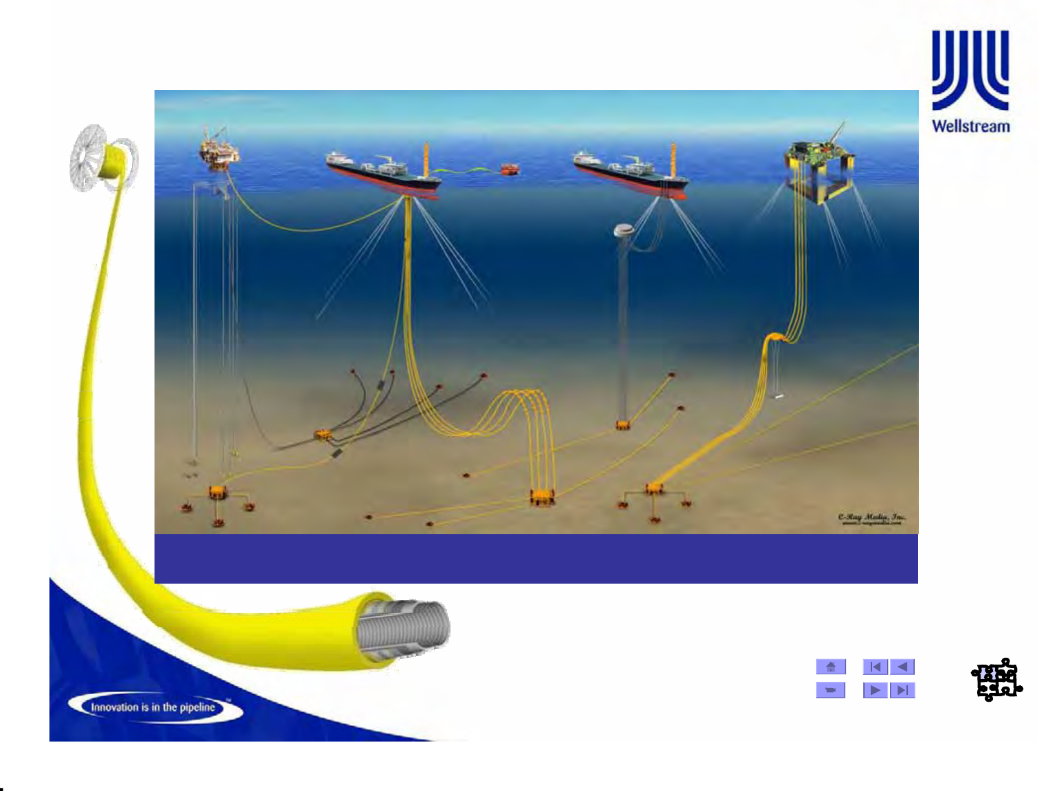
What are Flexible Pipes Used For?
Designed to have the strength and durability associated with rigid steel pipes,
flexible systems are often the only solution for risers in dynamic environments
© Wellstream International Limited. Duplication in full or in part is prohibited.
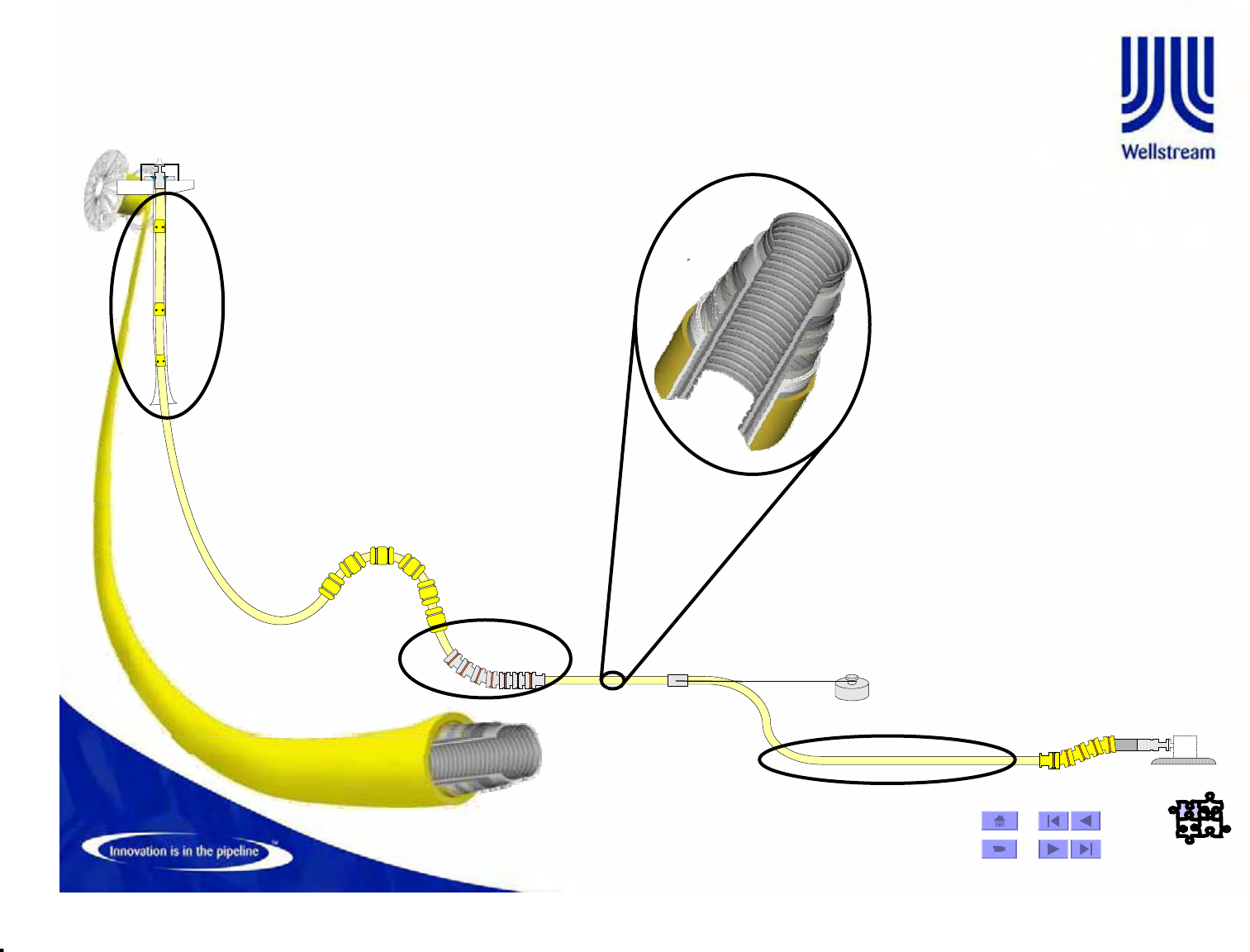
What is a Flexible Pipe?
• Unbonded flexible pipes consist of concentric layers of metallic wires,
tapes and extruded polymers designed to form a structure that
addresses the specific environmental requirements and characteristics
of the transported fluids
Flexbarrier - Polymer
HDPE, PA11/PA12, PVDF
Flexlok
Carbon Steel
Flexshield - Polymer
TPE, HDPE, PA11/PA12
Flexinsul
Syntactic Foam
Flexbody
Alloy steel Flextensile
Carbon Steel
End fitting Composition
© Wellstream International Limited. Duplication in full or in part is prohibited.
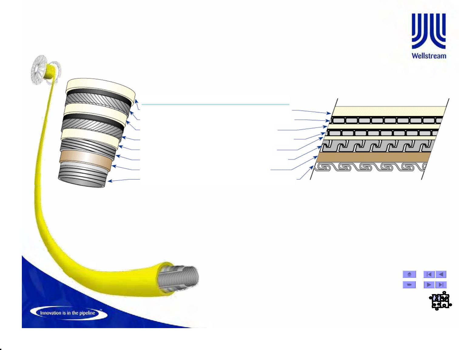
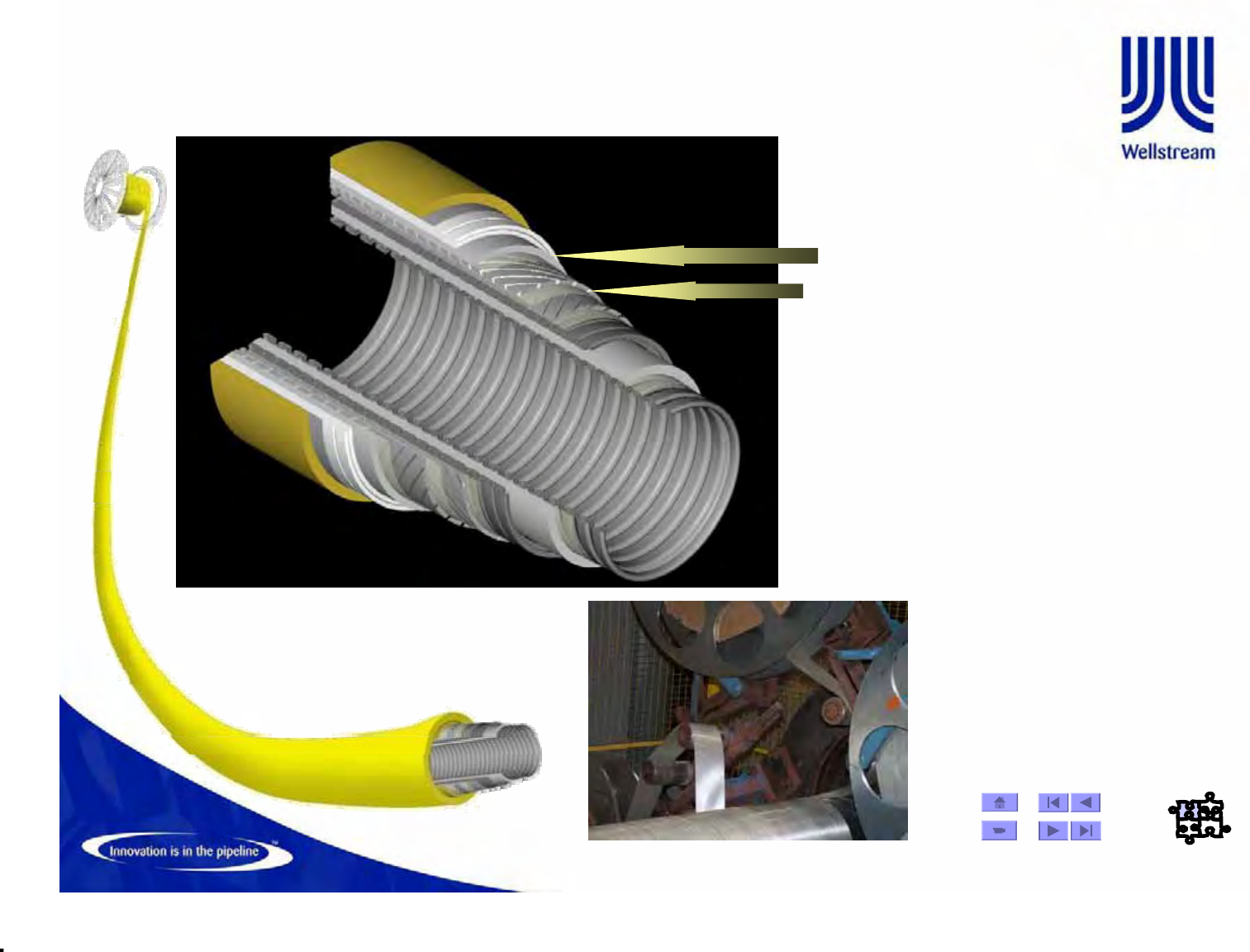
OUTER SHEATH POLYMER EXTERNAL FLUID BARRIER
TENSILE ARMOR CARBON STEEL TENSILE STRENGTH LAYER
ANTI-WEAR POLYMER ANTI-WEAR LAYER
TENSILE ARMOR CARBON STEEL TENSILE STRENGTH LAYER
ANTI-WEAR POLYMER ANTI-WEAR LAYER
PRESSURE ARMOR CARBON STEEL HOOP STRENGTH LAYER
INTERNAL PRESSURE POLYMER FLUID BARRIER
CARCASS STAINLESS STEEL COLLAPSE RESISTANT LAYER
LAYER MATERIAL FUNCTION
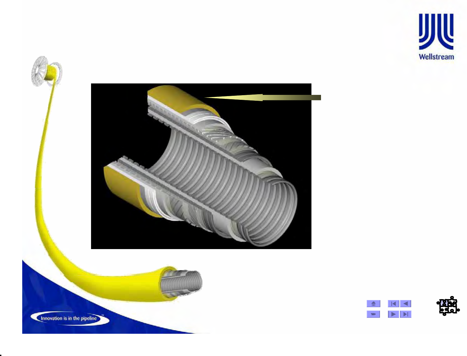
Flexible Pipe Construction
Flexible pipe is a technically challenging, multi-layer structure of
helically wound metallic wires and tapes and extruded
thermoplastics
•Regarding Aplication
– Risers : Static or Dynamic Application
– Flowlines : Static Application
•Regarding the Internal Fluid
– Smooth bore : Water Injection
– Rough Bore : Oil and Gas
•Regarding H2S presence
– Sweet service : with H2S
– Sour service : without H2S
© Wellstream International Limited. Duplication in full or in part is prohibited.
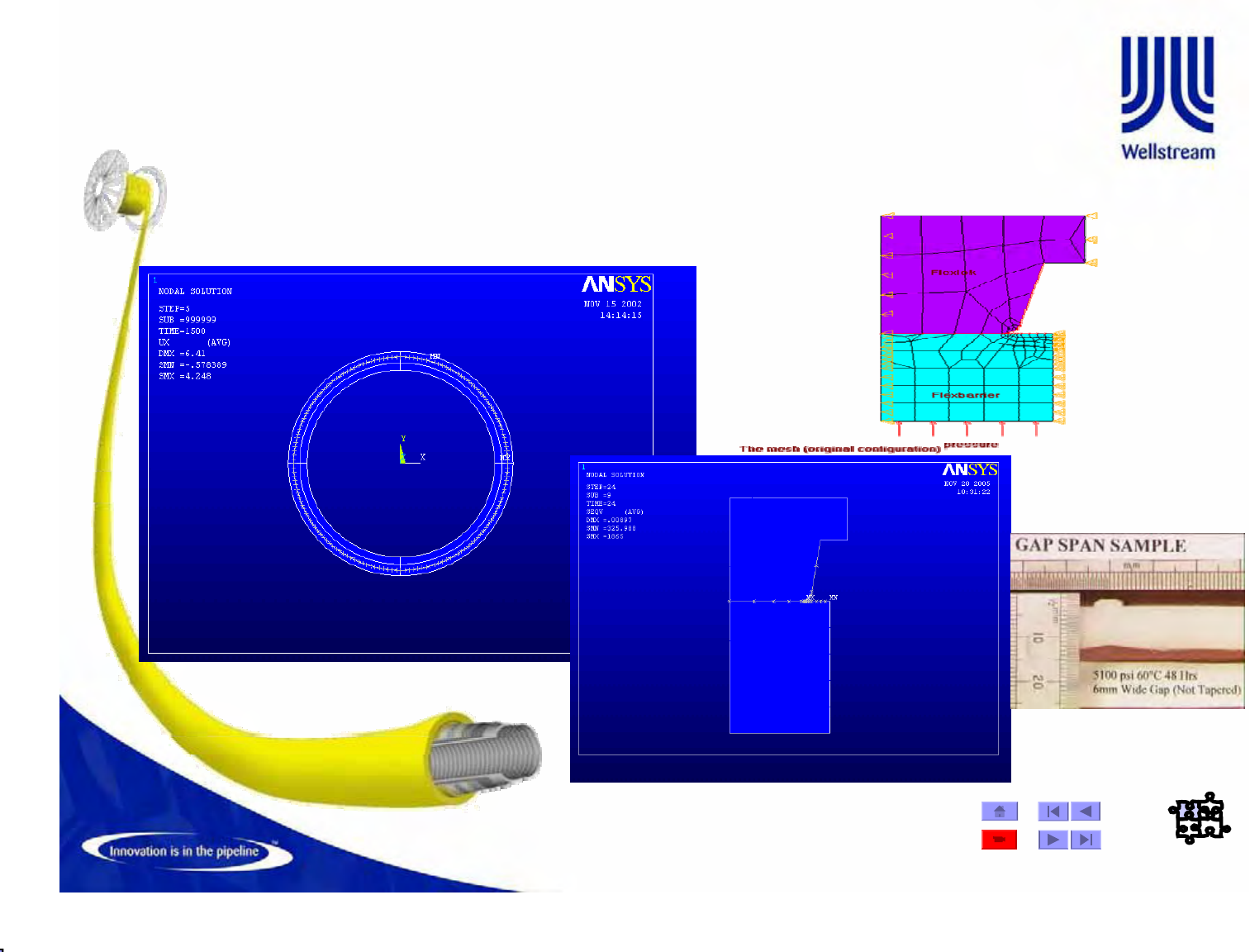
Key Design Considerations
• Gross structural integrity
(tension, pressure)
• Riser interaction (clashing,
interference and
entanglement)
• Fatigue (curvature and tension
ranges)
• Local analysis
– Gap span
– Flexlok stress analysis
– Corrosion fatigue
– Material compatibility
• Touch down point
– Abrasion
– Local armour buckling (bird-caging)
• Collapse
• On-Bottom Stability
• Upheaval Buckling
© Wellstream International Limited. Duplication in full or in part is prohibited.
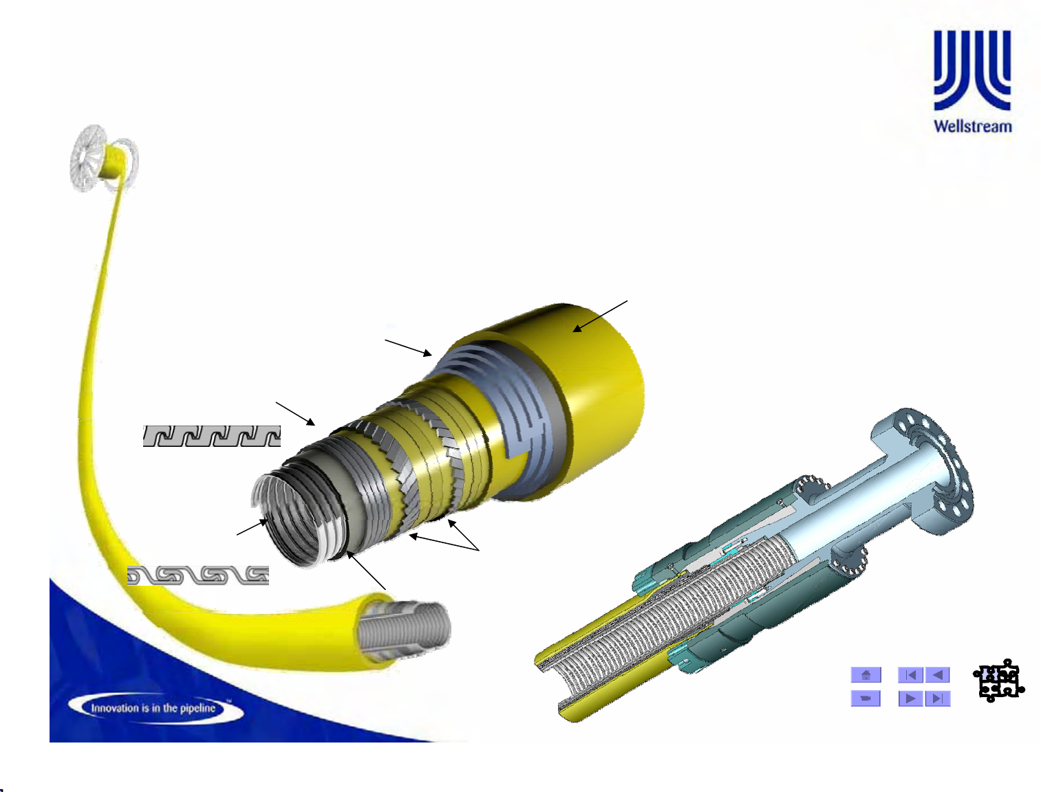
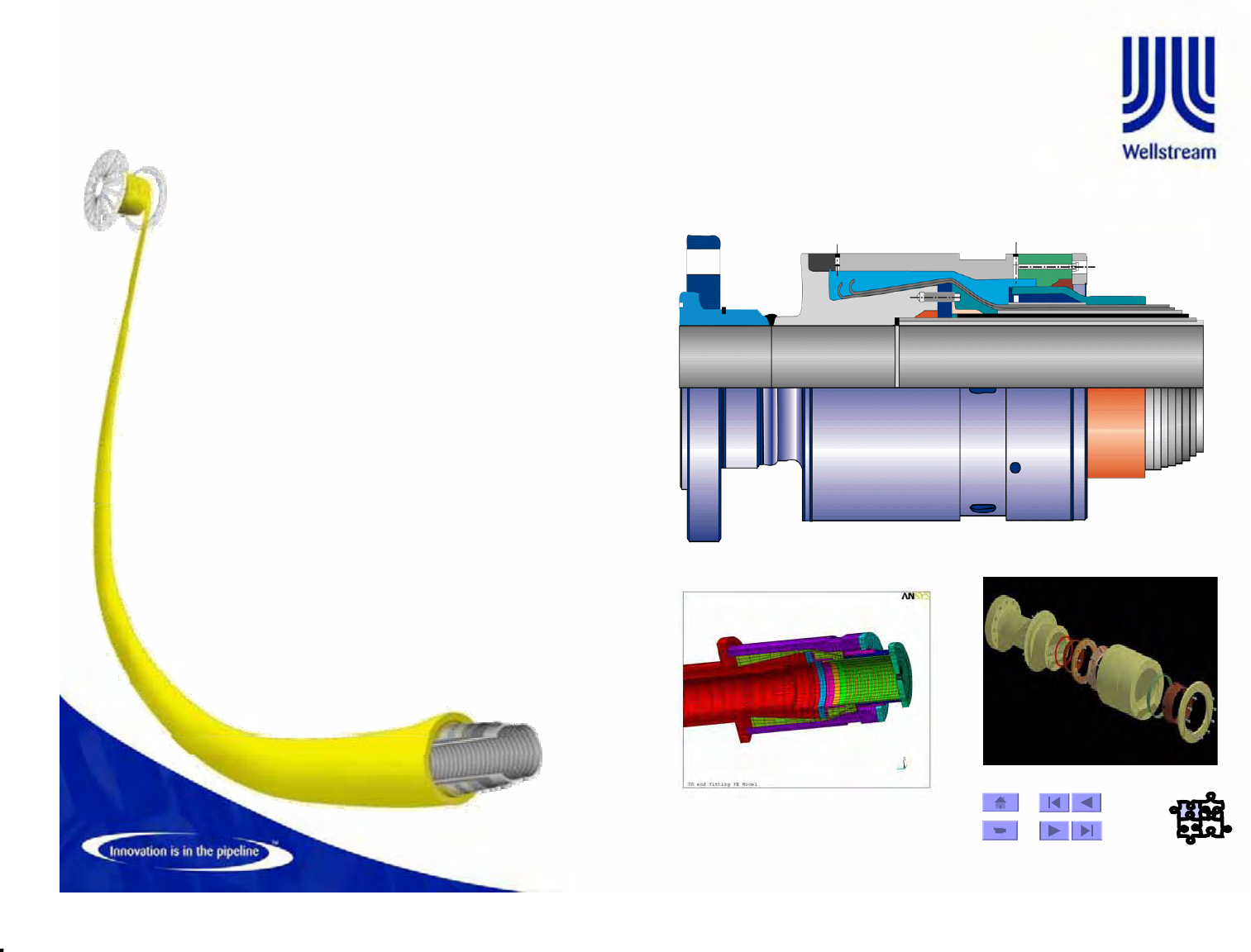
Main Ancillaries
End Fittings
• End fittings are custom designed for
each flexible pipe structure
• Terminations can be any design –
API/ANSI flanges, hubs, welded, or
other
• Stronger than pipe in burst and failure
tension
• Most common structural material is
AISI 4130 low alloy steel
• Common coatings include electrolysis
nickel plating, and various epoxies.
• Assembly is a manual process
© Wellstream International Limited. Duplication in full or in part is prohibited.
Main Ancillaries
IP - Anode Clamp Design
Installation Sequence
Before the installation,
the ROV clean the
Endfitting surface using
a steel brush to
guarantee a better
electrical contact of the
Anode Clamp.
After that, the
installation process is
illustrated in the figure
aside.
Anode Clamp Design
Used to protect flexible pipe
end fittings against corrosion
© Wellstream International Limited. Duplication in full or in part is prohibited.
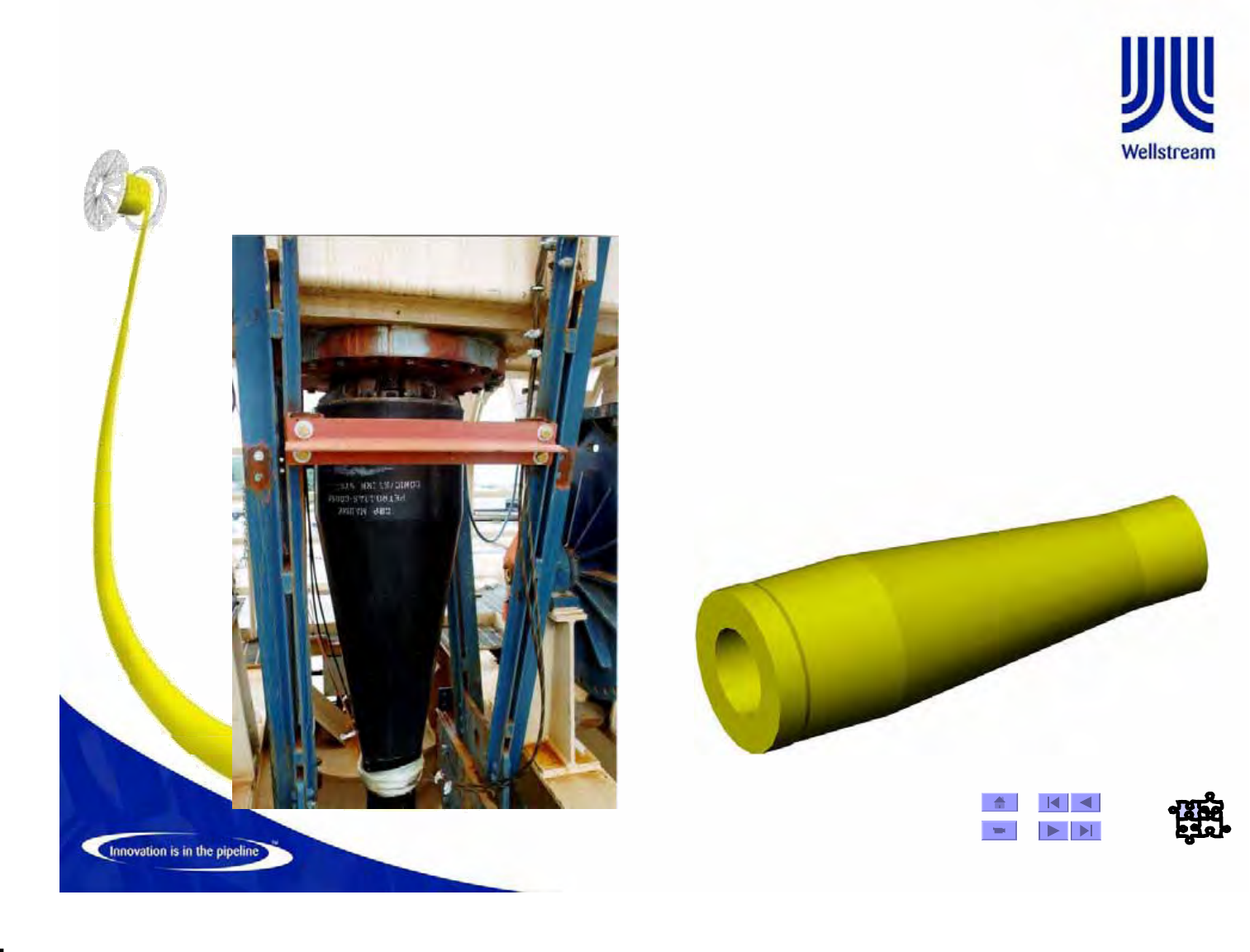
• Required for dynamic risers
• Polyurethane cone that moves bending moment from
base of end fitting
• Installed remotely or diver assisted.
Main Ancillaries
Bend Stiffener
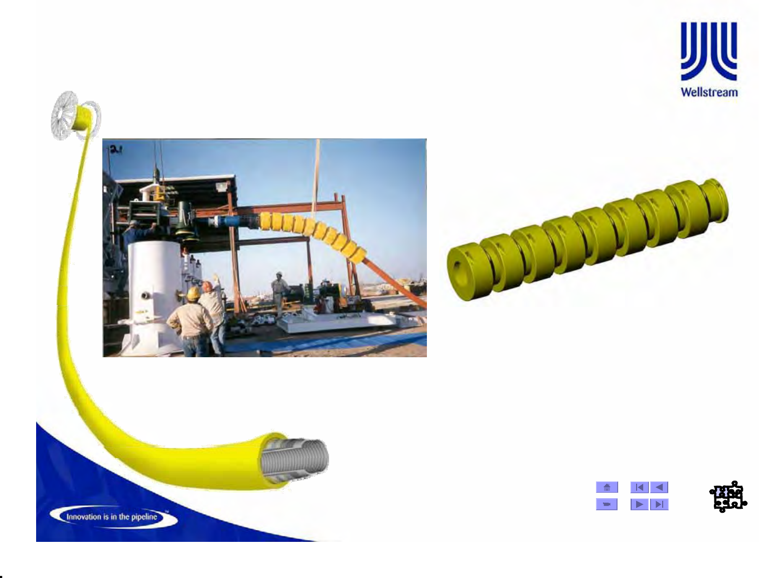
© Wellstream International Limited. Duplication in full or in part is prohibited.
• Used at connections to wellhead, PLEM, manifold, etc.
• Prevents overbending. Installation aid when pipe deployed with subsea hardware
• Polyurethane units which can be installed offshore
• Steel solutions also available at lower cost but must be packaged in plant
Main Ancillaries
Bend Restrictor
© Wellstream International Limited. Duplication in full or in part is prohibited.
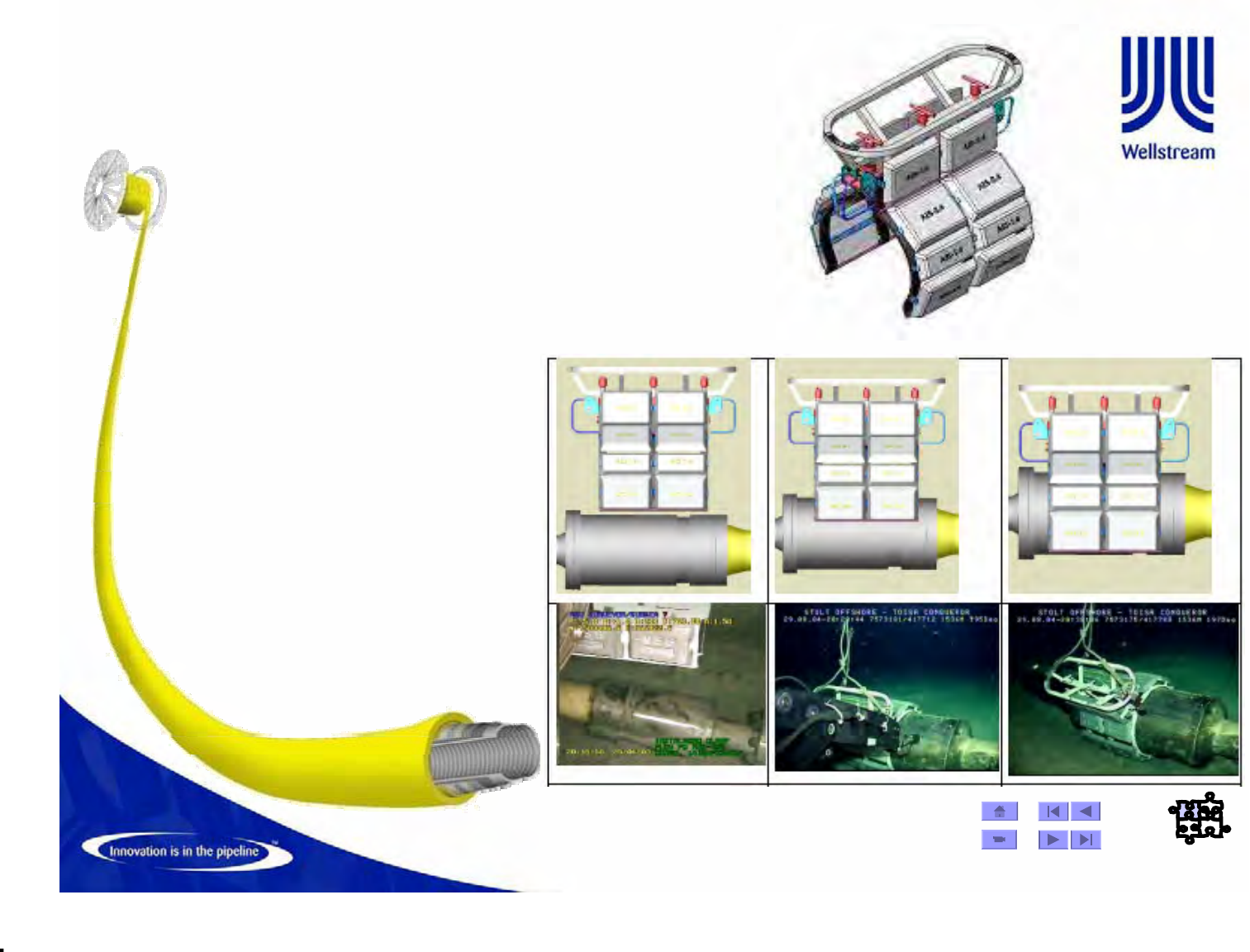
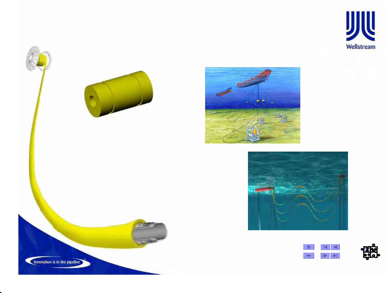
• Floatation attached to result in
desired riser configuration
• Both concentrated and distributed
• Clamps required for concentrated
buoy to make connection to arch
Main Ancillaries
Buoyancy Modules
© Wellstream International Limited. Duplication in full or in part is prohibited.
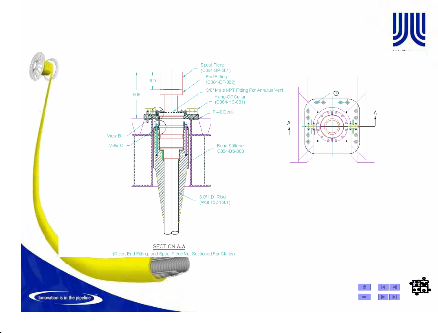
Main Ancillaries
Hang Off Clamp

© Wellstream International Limited. Duplication in full or in part is prohibited.
Manufacture -13
Flexible Pipe Standards
•API 17J - Specification for Unbonded Flexible Pipe
•Petrobras NI-2409-A - Flexible Pipe Specification - 2003
–Must be in compliance on all Petrobras Projects.
•ISO 13628 - Petroleum natural gas industries - Drilling and
production equipment - Design and operation of subsea system-
Part 2: Flexible pipe systems for subsea and marine applications.
•Bureau Veritas NI 364 DTO ROO E - Non-bonded Flexible Steel
Pipes used as Flowlines
•DNV Rules for Flexible Pipe
•Other oil company specifications
–- ALL SUPERSEDED BY API 17J
•RP17B - Recommended Practice for Unbonded Flexible Pipe
(sister document to API 17J)

© Wellstream International Limited. Duplication in full or in part is prohibited.
Manufacture -14
Technical Documentation Requirements
for Flexible Pipe
•Design Premise
•Design Load Report
•Design Report (with Riser System / Service Life Analysis)
•Fabrication Specification
•Operation Manual
•Manufacturing Quality Plan
•Data Book
© Wellstream International Limited. Duplication in full or in part is prohibited.
Manufacture -15
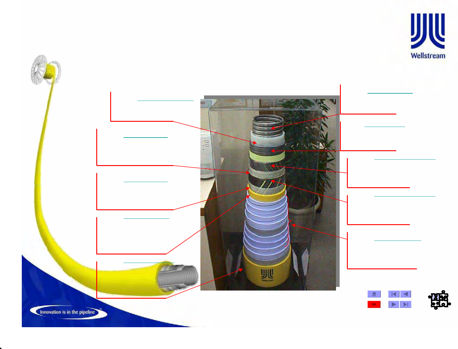
Petrobras - Marlim Sul
Pipe ID : 6 inches
Water Depth : 1500m
Pressure Rating : 20.68 Mpa
Design Temperature : 60 Deg. C
Function : Oil / Gas Insulated Flowline
Layer: FLEXBODY TM
Function: Collapse Resistance
Material: Stainless Steel
Thickness: 8,40 mm
Layer: FLEXBARRIER TM
Function: Seal Internal Fluid
Material: Nylon PA-11
Thickness: 7,00 mm Layer: FLEXLOK TM
Function: Provides Hoop Strength
Material: Carbon Steel
Thickness: 6,35 mm
Layer: FLEXTAPE TM
Function: Birdcaging Resistance
Material: High Strength
Glass Filament
Thickness: 0,81 mm
Layer: FLEXTAPE TM
Function: Birdcaging Resistance
Material: High Strength
Glass Filament
Thickness: 0,81 mm
Layer: FLEXTENSILE 1 TM
Function: Provides Hoop
and Axial Strength
Material: Carbon Steel
Thickness: 3,00 mm
Layer: FLEXTENSILE 2 TM
Function: Provides Hoop
and Axial Strength
Material: Carbon Steel
Thickness: 3,00 mm
Layer: FLEXWEAR TM
Function: Limit Steel Layer
Wear, Constrain Flextensile
Wires, Manufacturing Aid
Material: HPDE
Thickness: 5,00 mm
Layer: FLEXINSUL TM
Function: Decrease Heat Loss
Material: Syntetic Foam
PT7000
Thickness: 40,00 mm (total)
Layer: FLEXSHIELD TM
Function: Environmental
Protection
Material: HPDE
PT7000
Thickness: 10,00 mm
© Wellstream International Limited. Duplication in full or in part is prohibited.
Manufacture -16
Flexible Pipe Design Make-up
Flexbody
Flexbody™
™-
-
(Internal Carcass)
(Internal Carcass)
The Flexbody is a
corrugated metallic tube
with a specified internal
diameter. The Flexbody
supports the extruded
fluid barrier and
prevents collapse from
hydrostatic pressure or
crushing loads applied
during pipe operation.
•Provides collapse resistance by forming into an interlocking spiral
© Wellstream International Limited. Duplication in full or in part is prohibited.
Manufacture -18
Flexible Pipe Design Make-up
Flexbarrier
Flexbarrier™
™-
-
(Internal Pressure Sheath)
(Internal Pressure Sheath)
The Flexbarrier is a
polymer layer extruded
over the Flexbody to form
a boundary for the
conveyed fluid. The
Flexbarrier material is
selected to be chemically
resistant to the conveyed
fluid and unaffected by its
service conditions.
Material types
HDPE PA11/PA12 PVDF
Increasing temperature resistance
Increasing temperature resistance
Increasing chemical compatibility
Increasing chemical compatibility
© Wellstream International Limited. Duplication in full or in part is prohibited.
Manufacture -20
Flexible Pipe Design Make-up
Flexlok
Flexlok™
™-
-
(Pressure Armour)
(Pressure Armour)
The Flexlok is a steel hoop
strength layer consisting of
circumferentially wound
profiled wire to resist to
internal pressure and
bending.
The Z-shaped wire is
profiled to allow interlocking
of the edges as they are
formed around the pipe.
© Wellstream International Limited. Duplication in full or in part is prohibited.
Manufacture -22
Flexible Pipe Design Make-up
The Tensile
Armor layer is a
helical steel
armor layer that
resists internal
pressure and
axial tension.
Flextensile
Flextensile™
™-
-
(Tensile Armour)
(Tensile Armour)
© Wellstream International Limited. Duplication in full or in part is prohibited.
Manufacture -24
Flexible Pipe Design Make-up
Flexwear
Flexwear™
™-
(Anti-wear Layer)
The Flexwear is a thin
polymer tape layer applied
between any two adjacent
metallic layers, and such
prevents metal-to-metal
contact between the layers
to prevent wear.
Flextape
Flextape™
™-
Tape layers are applied
over the tensile armors
as a manufacturing aid to
prevent “birdcaging”.

© Wellstream International Limited. Duplication in full or in part is prohibited.
Manufacture -26
Flexible Pipe Design Make-up
Flexinsul
Flexinsul™
™-
-
(Insulation)
(Insulation)
Flexinsul is a thermal
insulation layer used
to limit heat loss
through the pipe wall
to the surrounding
environment.
© Wellstream International Limited. Duplication in full or in part is prohibited.
Manufacture -28
Flexible Pipe Design Make-up
Flexshield
Flexshield™
™-
-
(External Sheath)
(External Sheath)
Flexshield is an
external polymer barrier
applied to resist
mechanical damage
and intrusion of
seawater.
© Wellstream International Limited. Duplication in full or in part is prohibited.
Manufacture -30
Pipe Structure Design Verification
Design Criteria
Pipe Wall Design
Stress & Strain,
Anal. Local Analysis
Global Dyn. Analysis
Local FE Analysis
Service Life
Analysis
See Figures
19, 20 API RP 17B
for more detailed
process charts for
static flowlines
and dynamic risers
© Wellstream International Limited. Duplication in full or in part is prohibited.
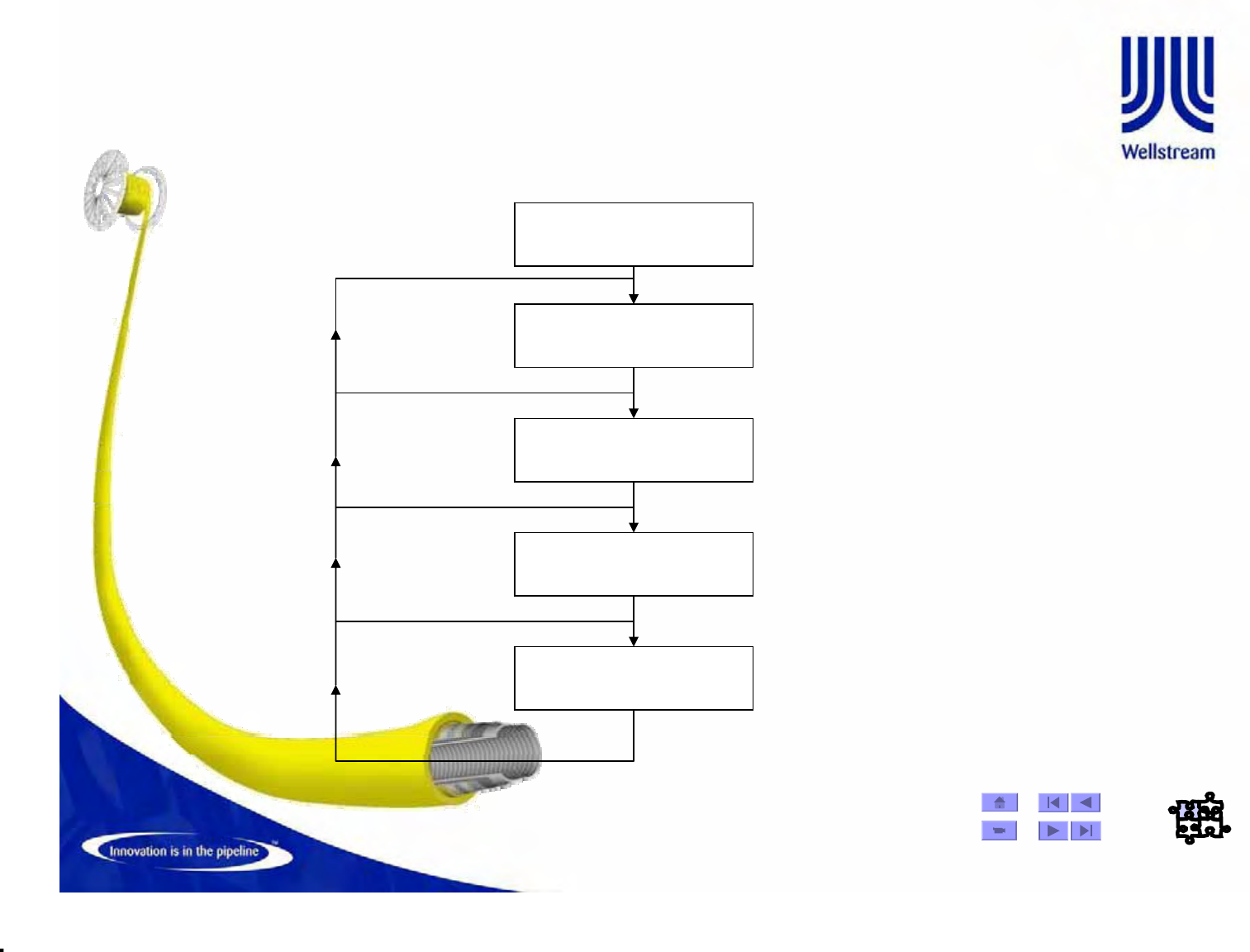
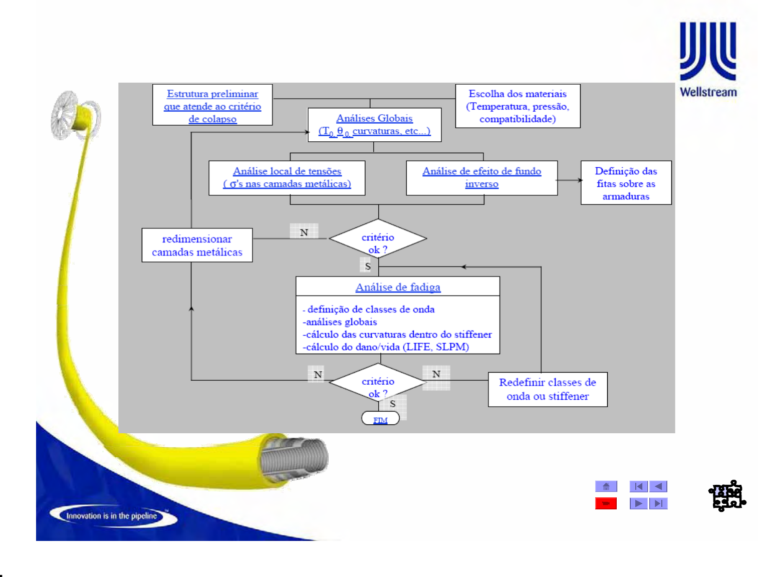
Flexible Pipe Design Flowchart
© Wellstream International Limited. Duplication in full or in part is prohibited.
Preliminary Design, Fluid Compatibility & Collapse & Local
Stress
The first design step is execute preliminary collapase, gas permeation, creep and
fluid compatibility to define the proposed pipe design
© Wellstream International Limited. Duplication in full or in part is prohibited.
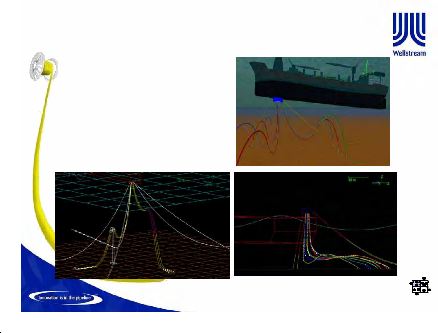
GLOBAL ANALYSIS - STRUCTURAL
• First step is to define the riser
configuration based on:
–Water Depth
–Vessel Type
–Environmental
Conditions
–Flexible ID
–Minimum Service Life
Specification
© Wellstream International Limited. Duplication in full or in part is prohibited.
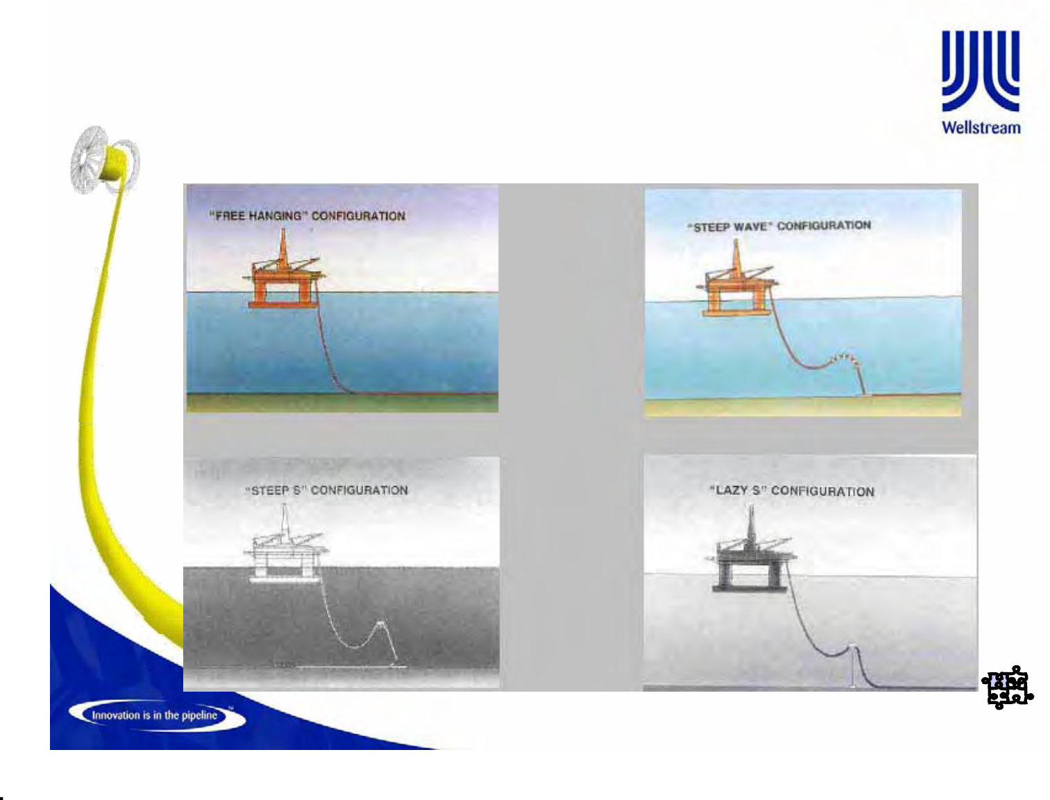
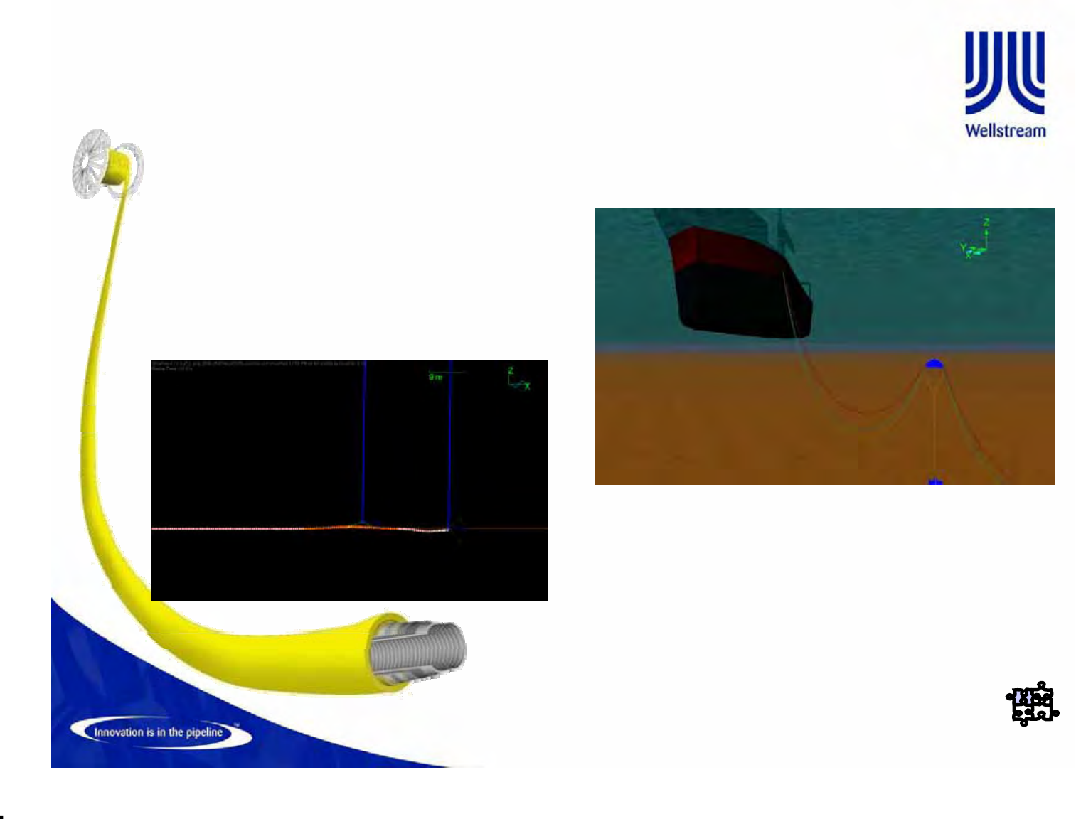
GLOBAL ANALYSIS – STRUCTURAL
RISER CONFIGURATION EXEMPLES
© Wellstream International Limited. Duplication in full or in part is prohibited.
GLOBAL ANALYSIS - STRUCTURAL
–Installation
–Recurrent Operation
–Extreme Operation
–Abnormal Conditions
• Once the configuration is defined, a non-linear dynamic structural analysis
is performed in order to estimate typical loads experienced by the flexible
pipe during:
• API 17B provides
recommendations on how to
perform the analysis
• Petrobras has its own specification
with mandatory requirements
SIRI_az202_GA-11-1-1.avi
© Wellstream International Limited. Duplication in full or in part is prohibited.
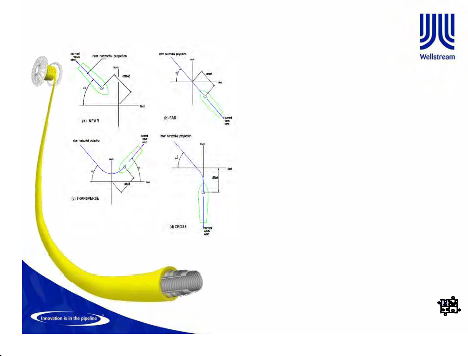
GLOBAL ANALYSIS - STRUCTURAL
• General approach is to run several load
cases (PB spec request aprox. 96 load
cases) in order to determine the most
severe combinations of:
–Wave (10yr or 100yr RP)
–Current (10yr or 100yr RP)
–Offsets (intact or broken mooring
system)
• The environmental conditions must be
supplied by the client
• Petrobras have specific documents
called METOCEANs that provide all
necessary information to perform the
analysis
© Wellstream International Limited. Duplication in full or in part is prohibited.
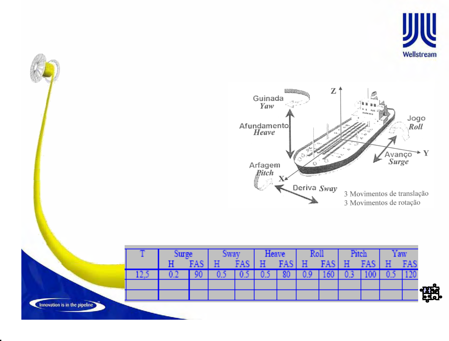
GLOBAL ANALYSIS - STRUCTURAL
• Vessel behavior are simulated by
a matrix loaded into the
commercial software
(Orcaflex/Flexcom)
• This table specify the vessel
displacement/rotations for all
vessel degrees of freedom in
terms of wave height and period.
• On this way, the environmental
condition influence can be
translated in vessel movements
and rotation that will impose
loads on the riser.
© Wellstream International Limited. Duplication in full or in part is prohibited.
GLOBAL ANALYSIS - STRUCTURAL
–Top Tension
–Tension@Angle Envelop
–Curvature on TDP
–Minimum Tension on TDP
(Birdcaging)
–Suspended length
–Anchoring Loads
• The relevant results often depend on riser configuration.
• For a free hanging catenary systems (most common configuration
in Brazil), the most important results are:
© Wellstream International Limited. Duplication in full or in part is prohibited.
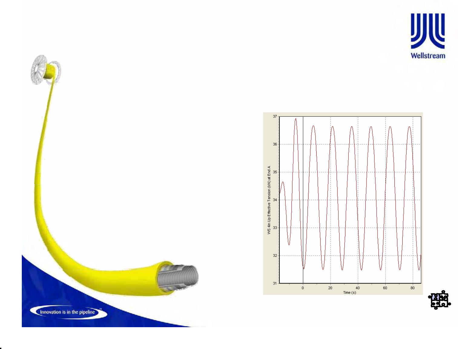
GLOBAL ANALYSIS – Service Life
• Once the riser is proven to resist to the most severe
environmental conditions, a service life analysis is performed in
order to verify the suitability of the riser against a specified service
life
• Petrobras has its own specification that drives the fatigue analysis.
On this specification, the global analysis load cases are related
with a number of incidences
• This way, the tension extracted from the load cases can be
associated to a number of cycles and an accumulated fatigue
damage and life can be calculated based on Palmgreen-Miner
rule
• The load cases are based on annual environmental conditions
• Petrobras normally specify 20 years of service life with a safety
factor of 10
© Wellstream International Limited. Duplication in full or in part is prohibited.
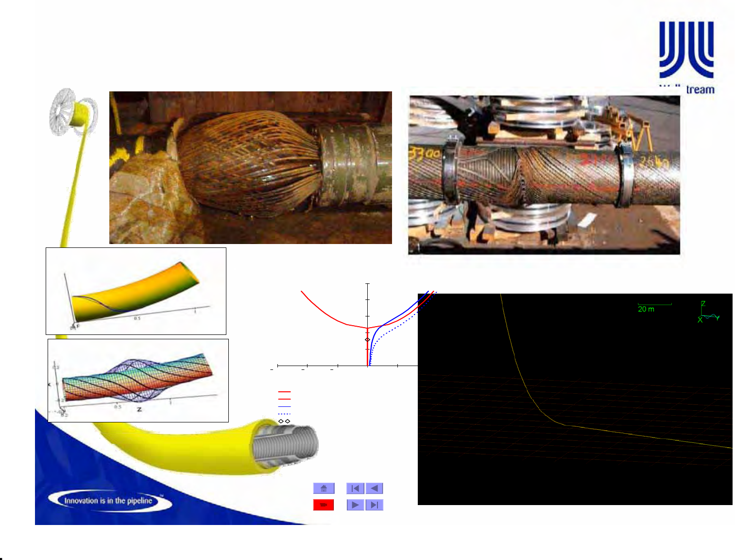
LOCAL ANALYSIS BIRD CAGE
Local BirdCage Analysis FEA & STRAIN ENERGY
Lateral Deflection (Amplified )
0.015 0.01 0.005 0 0.005 0.01 0.015
110 8
210 8
310 8
410 8
510 8
StraightHlex
StraightHelix
BentHelix
BentHelix(Calib)
ApplCompression
StraightHlex
StraightHelix
BentHelix
BentHelix(Calib)
ApplCompression
Equilibrium Path
Deflection
Axial Compression
© Wellstream International Limited. Duplication in full or in part is prohibited.
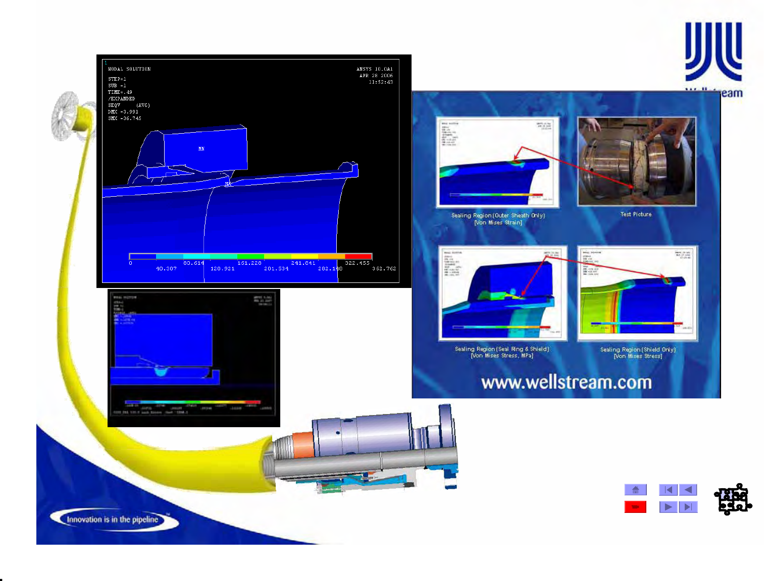
End Fitting Outer Sheath Holding System FEA Model
© Wellstream International Limited. Duplication in full or in part is prohibited.
Material Qualification
To specified environmentsChemical resistance
only armor wires with yeild stress >= 700 Mpa and/or ultimate stress >= 900
Mpa and exposed to cathodic protectionAPI 17J Sect. 6.2.4.6Hydrogen embrittlement
Pressure and tensile armors in dynamic applications onlyAPI 17J Sect. 6.2.4.5Fatigue resistance
Carcass onlyAPI 17J Sect. 6.2.4.4Erosion resistance
To specified environments (Armor wires only)API 17J Sect. 6.2.4.3Corrosion resistance
To specified environments (Armor wires only)API 17J Sect. 6.2.4.2SSC and HIC
Sour service applications only (Armor wires only)ASTM E92Hardness
ASTM A370Ultimate strength/elongation
ASTM A370Yield strength/elongation
Or ISO 8457-2ASTM A751Chemical composition
CommentsTest ProcedureTests
Test Procedures for Metallic Materials

© Wellstream International Limited. Duplication in full or in part is prohibited.
Material Qualification
Insulation material onlyASTM D570Water absorption Effectiveness to the UV stabilizerWeathering resistance Method C. PE only.ASTM D1693Environmental stress cracking API 17J Sect. 6.2.3.4Aging tests API 17J Sect. 6.2.3.3Fluid compatibilityCompatibility and aging
At design conditionsAPI 17J Sect. 6.2.3.2Blistering resistance
As a minimum to CH4, CO2, H2O and
methane, at design temp and pressAPI 17J Sect. 6.2.3.1Fluid permeabilityPermeation characteristics
Or glass transition temp (ASTM E1356)ASTM D746Brittleness temperature ASTM E1269Heat capacity ASTM D1525Softening point Method AASTM D648Heat distortion temperatures ASTM E831Coefficient of thermal expansion ASTM C177Coefficient of thermal conductivityThermal properties
ASTM D256Notch sensitivity Dynamic applications onlyASTM D671Fatigue
Or ASTM D1505ASTM D792Density Or ASTM D1044 or D1242ASTM D4060Abrasion resistance At design minimum temperatureASTM D256Impact strength
Hydrostatic pressure resistance ASTM D695Compression strength Or ASTM D2583ASTM D2240Hardness ASTM D638Modulus of elasticity ASTM E328Stress relaxation properties
ASTM D638Ultimate strength/elongation
ASTM D638Yield strength/elongation
Due to temperature and pressureASTM D2990Resistance to CreepMechanical/physical properties
CommentsTest ProcedureTestsCharacteristic
Test Procedures for Extruded Polymer Materials
© Wellstream International Limited. Duplication in full or in part is prohibited.
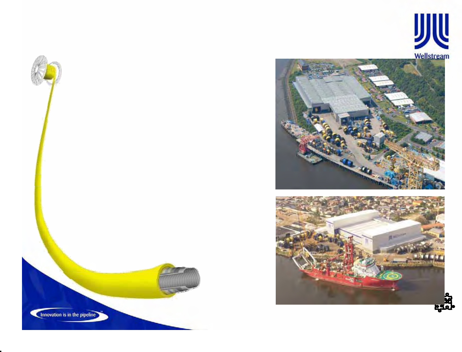
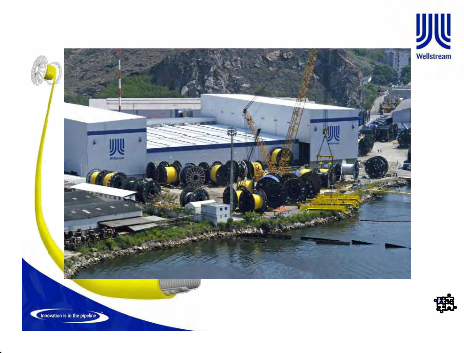
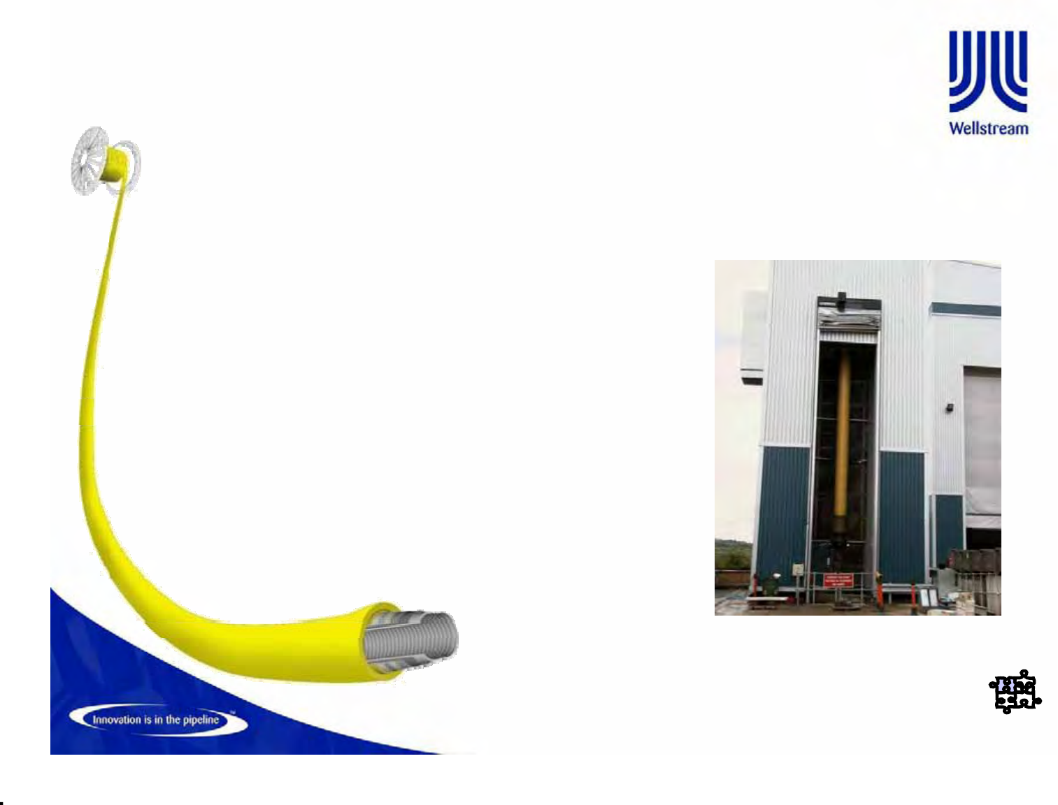
Offshore Facilities
• Newcastle, UK
– Operational since 1997
– Capability and experience to manufacture
the full range of offshore products from
2” - 16” diameters
– Annual production capacity of 260nkm
– Proven track record of operating at highest
standards required by industry
– In 9 years of manufacturing there have been
zero in-service failures
• Niterói, Brazil
– Commenced manufacturing on schedule in
May 2007
– Annual production capacity of 150nkm
– Expected product range: inside diameter of
2” to 12”
– Facility designed to allow future expansion
© Wellstream International Limited. Duplication in full or in part is prohibited.
Manufacturing Process
•The manufacturing of flexible pipes consists of 7 main stages, followed by assembly of end
fittings, testing and packaging
– Work stations are laid out to optimize the sequential manufacturing process
– Maximum flexibility in manufacturing to reel or carousel
– Equipment parameters are computer monitored and controlled throughout the process ensuring
consistency
– Quality control teams operate at each work station, throughout the length of the production run
– Continuous Improvement teams operate at each work station
Shield
Extrusion
Stage
Flexwear
TM
Stage
Insulation
Stage
Armour
Stage
Flexlok
TM
Stage
Barrier
Extrusion
Stage
Carcass Stage
Flexbody
TM
Flexbarrier
TM
Flexlok
TM
Flextensile
TM
Flexinsul
TM
Flexwear
TM
Flexshield
TM
Provides
collapse
resistance
Forms the fluid-
conveying
conduit
Provides
pressure
retention
capacity of pipe
structure
Provides axial
tension
strength
Enhances
thermal
properties
Reduces friction
between
metallic armour
wires
Protects
structural layers
from mechanical
damage and
ingress from sea
water
RERRTT or EE
R = Rotating equipment work centre E = Extrusion work centre
2 machines
maximise
production
output
Flexliner
TM
may
replace the
carcass and
Flexbarrier
TM
for smoothbore
applications
Flexpress
TM
used when
Flexlok
TM
alone
cannot provide
sufficient
strength
Increases burst
strength by
enhancing
hoop strength
of Flexlok
TM
Helical wrapping
of single or
multiple layers
of insulation
tape onto the
pipe
Supports tensile
armour wires
against buckling
outwards
Additional
external
protection can be
given by a
Flexgard
TM
T = Taping work centre
Shield
Extrusion
Stage
Flexwear
TM
Stage
Insulation
Stage
Armour
Stage
Flexlok
TM
Stage
Barrier
Extrusion
Stage
Carcass Stage Shield
Extrusion
Stage
Flexwear
TM
Stage
Insulation
Stage
Armour
Stage
Flexlok
TM
Stage
Barrier
Extrusion
Stage
Carcass Stage
Flexbody
TM
Flexbarrier
TM
Flexlok
TM
Flextensile
TM
Flexinsul
TM
Flexwear
TM
Flexshield
TM
Provides
collapse
resistance
Forms the fluid-
conveying
conduit
Provides
pressure
retention
capacity of pipe
structure
Provides axial
tension
strength
Enhances
thermal
properties
Reduces friction
between
metallic armour
wires
Protects
structural layers
from mechanical
damage and
ingress from sea
water
RERRTT or EE
R = Rotating equipment work centre E = Extrusion work centre
2 machines
maximise
production
output
Flexliner
TM
may
replace the
carcass and
Flexbarrier
TM
for smoothbore
applications
Flexpress
TM
used when
Flexlok
TM
alone
cannot provide
sufficient
strength
Increases burst
strength by
enhancing
hoop strength
of Flexlok
TM
Helical wrapping
of single or
multiple layers
of insulation
tape onto the
pipe
Supports tensile
armour wires
against buckling
outwards
Additional
external
protection can be
given by a
Flexgard
TM
T = Taping work centre
© Wellstream International Limited. Duplication in full or in part is prohibited.
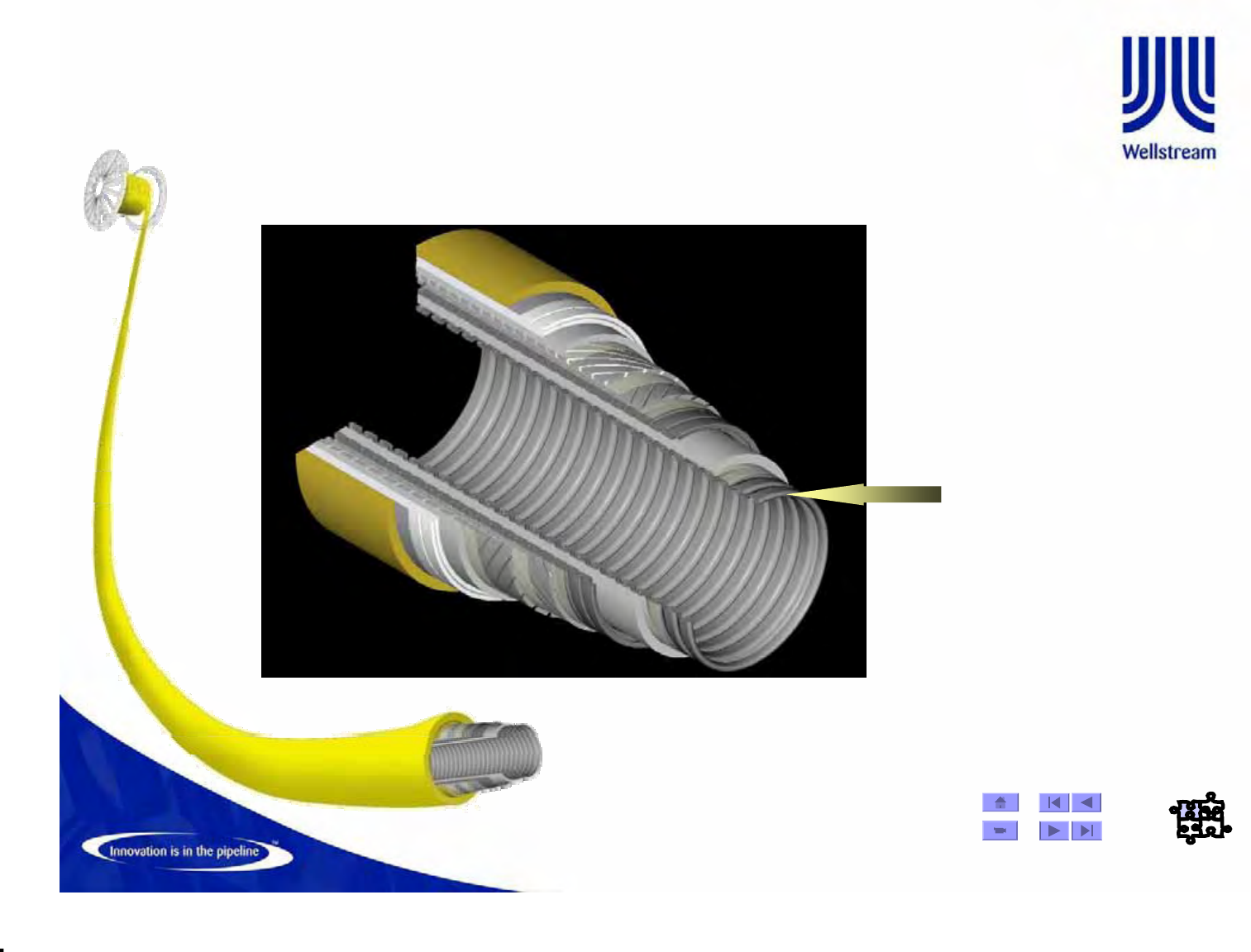
Flexible Pipe Construction Carcass
Carcass
Carcass -
-
The Carcass is a corrugated
metallic tube with a specified
internal diameter. The
Carcass supports the
extruded fluid barrier and
prevents collapse from
pressure or crushing loads
applied during pipe operation
Material Selection
Material Selection
Stainless 304L, 316 L
Duplex & AL6XN
© Wellstream International Limited. Duplication in full or in part is prohibited.
Manufacture -63
Carcass take up Reel
¾The carcass is taken upon a reel,
ready for the extrusion operation.
© Wellstream International Limited. Duplication in full or in part is prohibited.
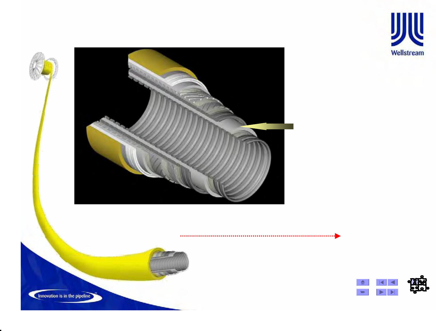
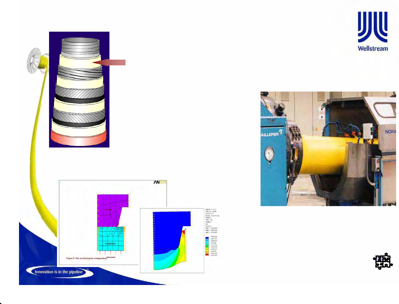
Flexible Pipe Construction Flexbarrier
Material Selection
Material Selection
PVDF, HDPE & PA-11/PA-12
Internal Pressure
Internal Pressure
Sheath
Sheath -
-
•For Flexbarrier (polymer fluid barrier)
the carcass is passed through the
extruder cross-head, where the resin
melt is applied over the carcass.
•Control of extruder volume and line
speed, coupled with use of specially
sized dies, determine the thickness of
the wall around the carcass.
•High Density Polyethylene (HDPE),
Nylon (PA11 or PA12), and
polyvinylidene fluoride (PVDF) as well
as other polymers are applied in this
process.
© Wellstream International Limited. Duplication in full or in part is prohibited.
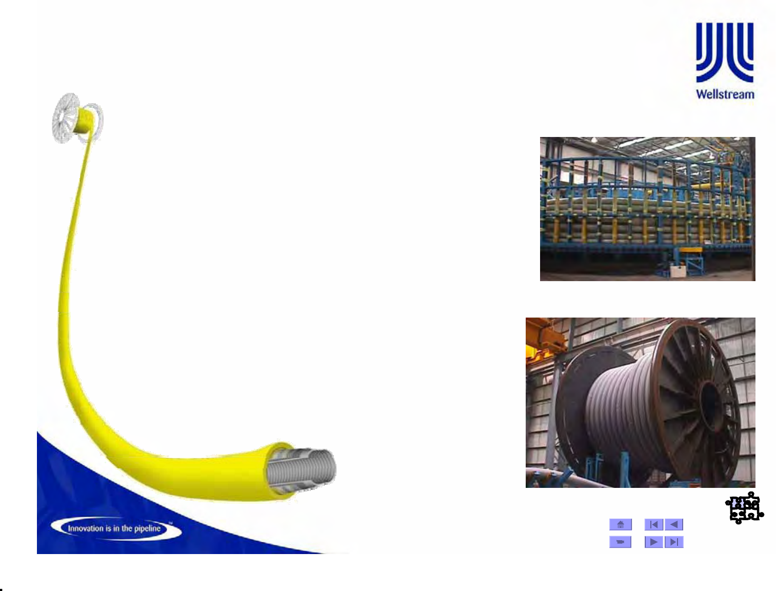
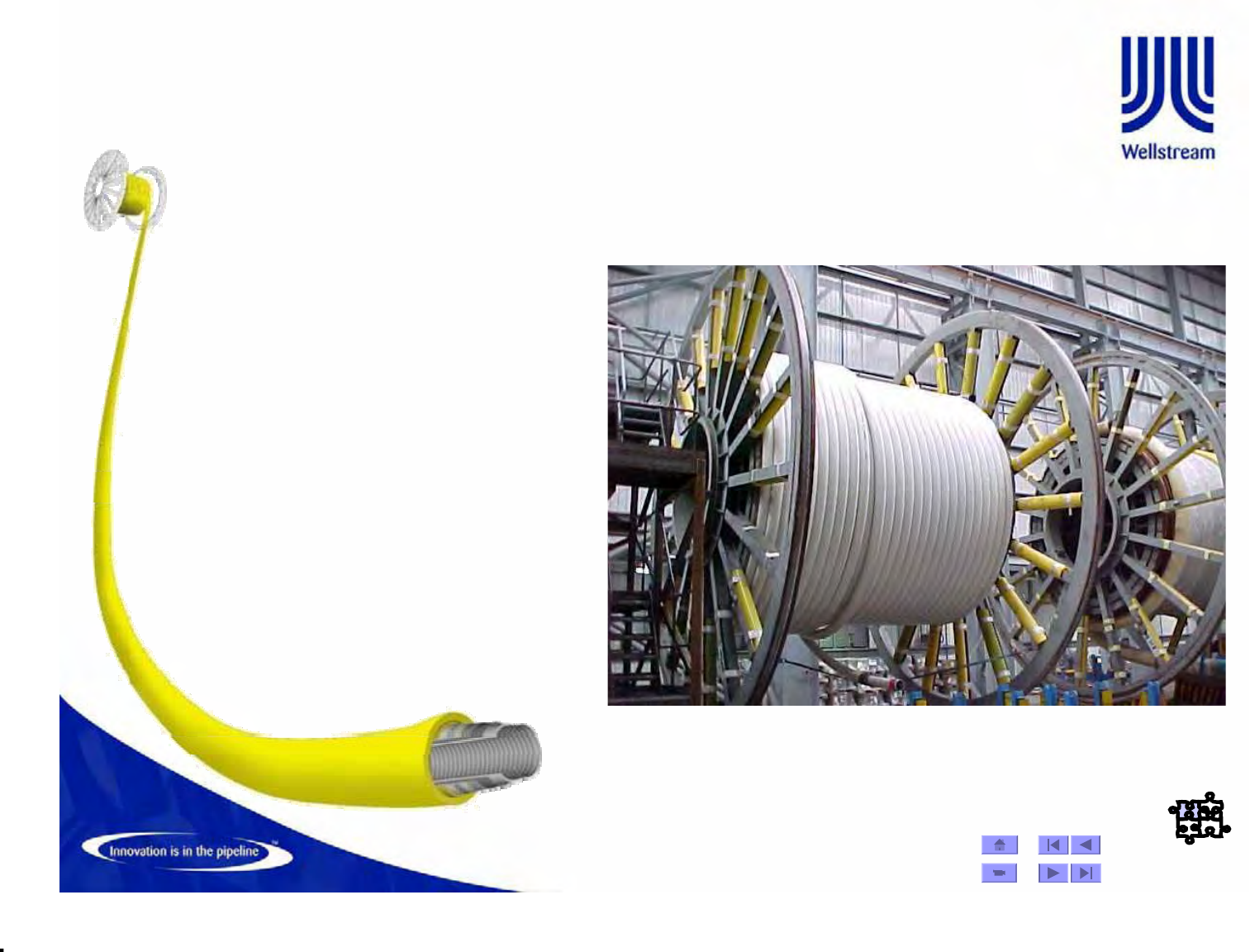
Manufacture -70
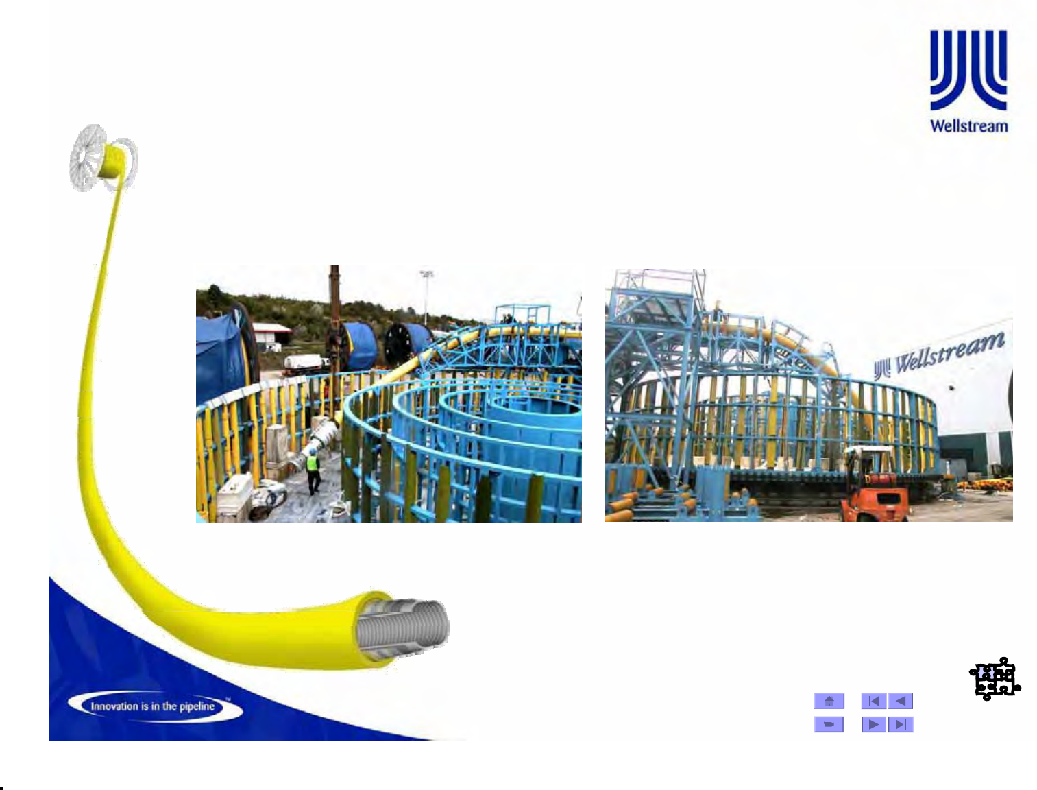
Production Reels & Carousel
¾The product is stored on reels or in a
carousel as it is processed through
each work centre.
¾The reels are also used to transport
the product to the customer.
¾Carousels are used when the length of
product exceeds the capacity of the
production reels or where the SBR is
large.
¾Transportation to the customer takes
place by loading the product on to the
vessel either on reels or in to the
vessels own carousel.
© Wellstream International Limited. Duplication in full or in part is prohibited.
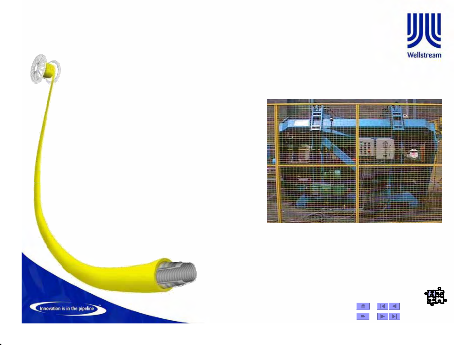
Manufacture -71
Caterpullers
¾There are two caterpullers
on each extrusion line, one
is used to pull the pipe
from the pay-off Rim drive
and feed it down the line at
a constant speed.
¾The other one is used to
pull the product through
the line at a constant speed
dictated by UT the catenary
setting. The catenary is a
necessary function of the
extrusion line.
© Wellstream International Limited. Duplication in full or in part is prohibited.
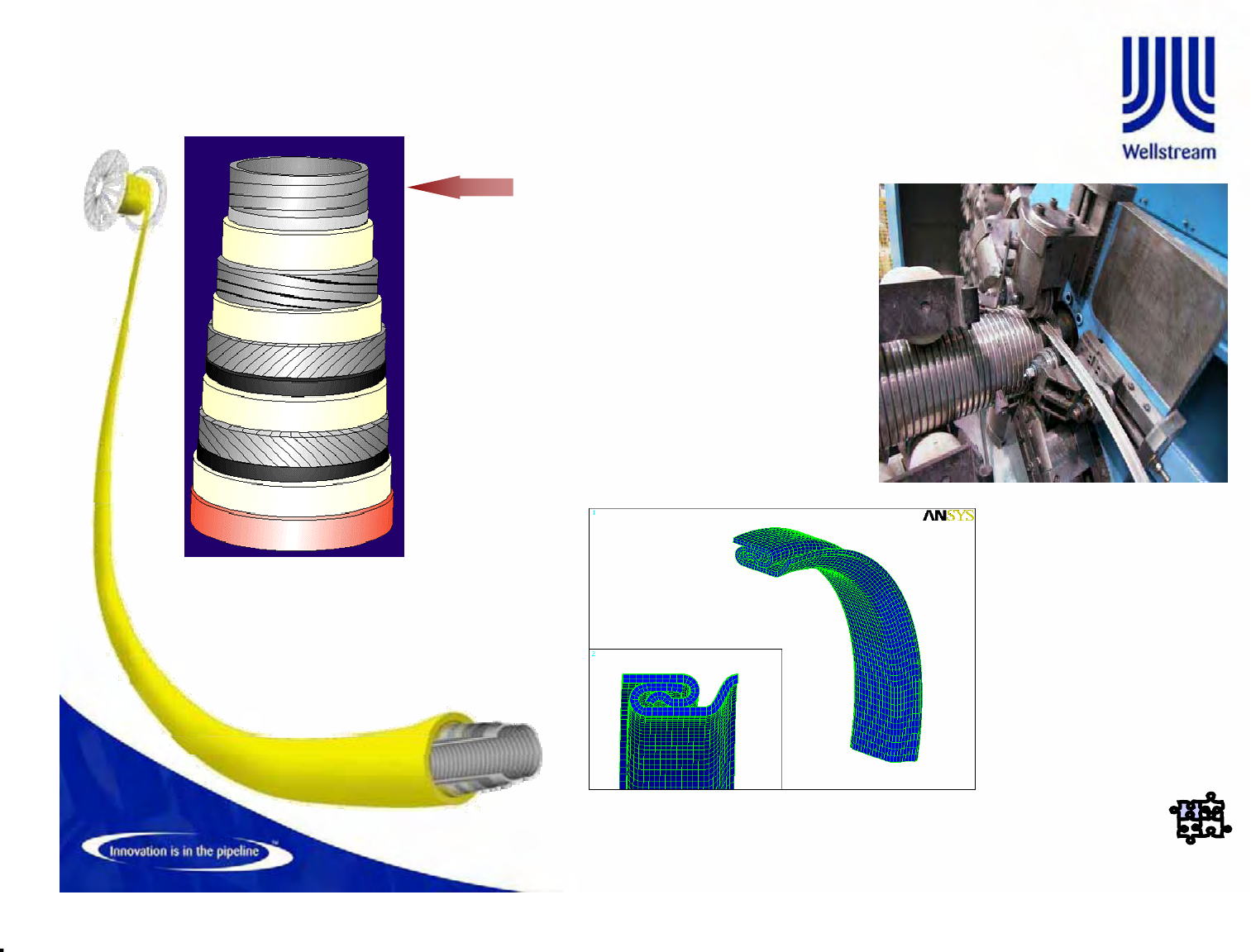
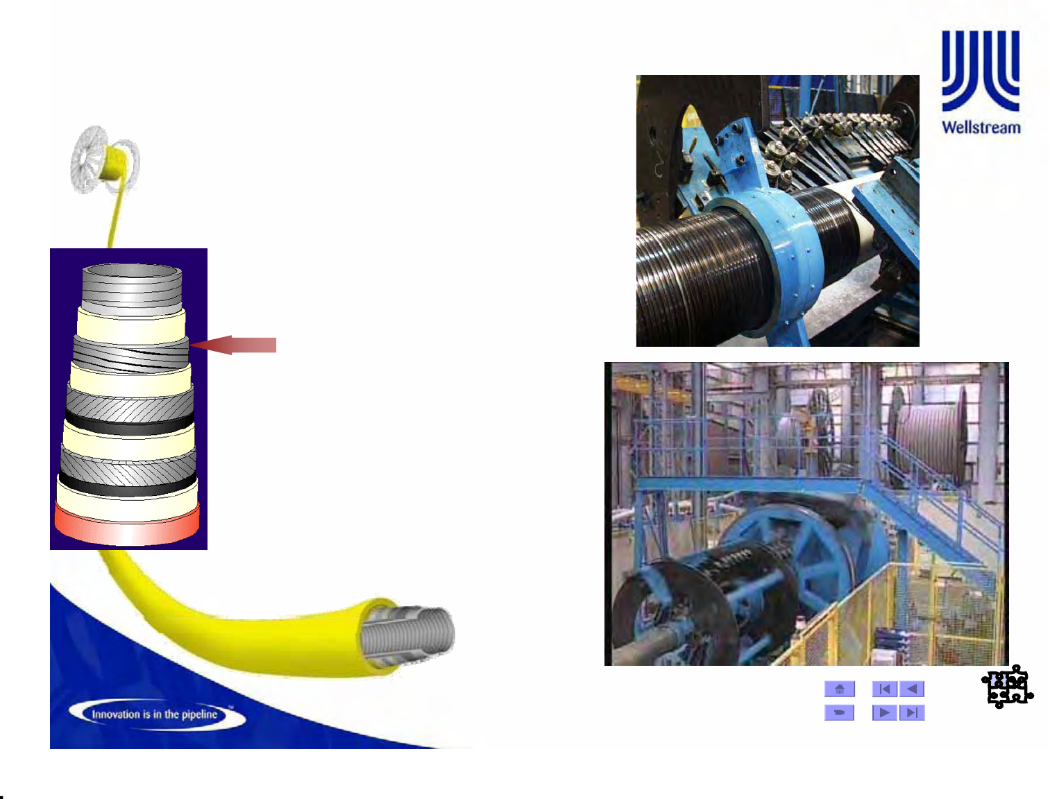
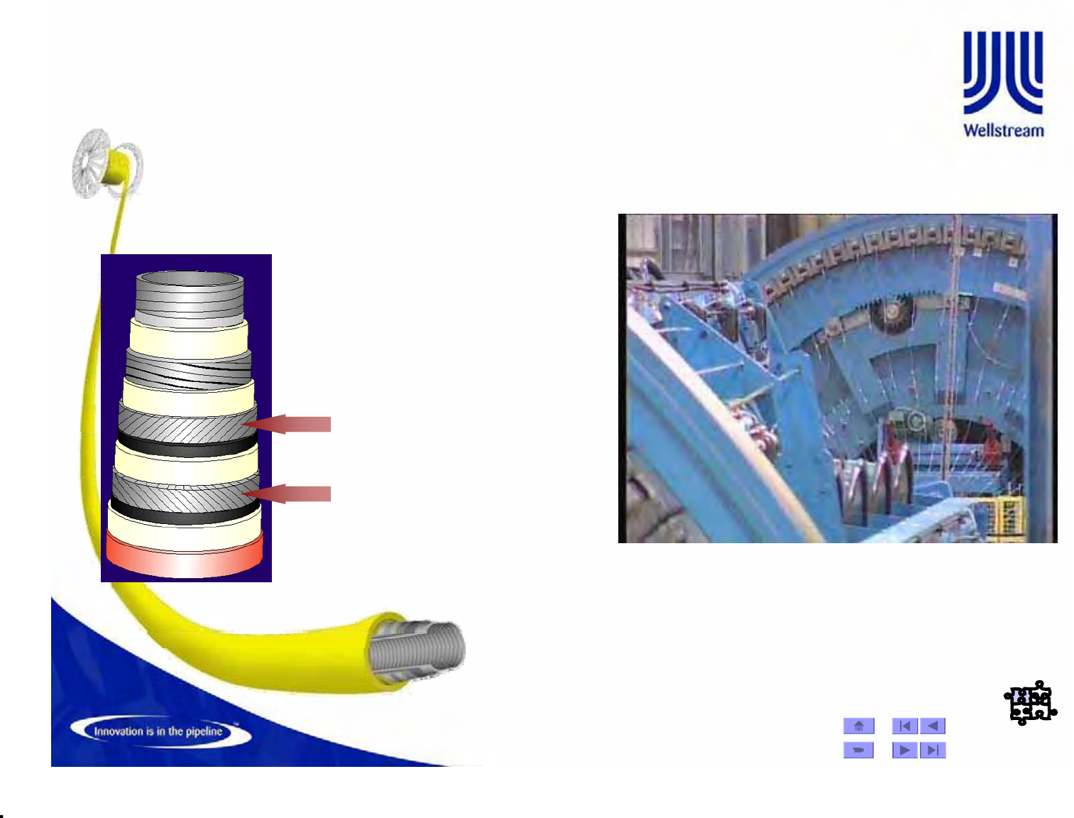
Manufacture -73
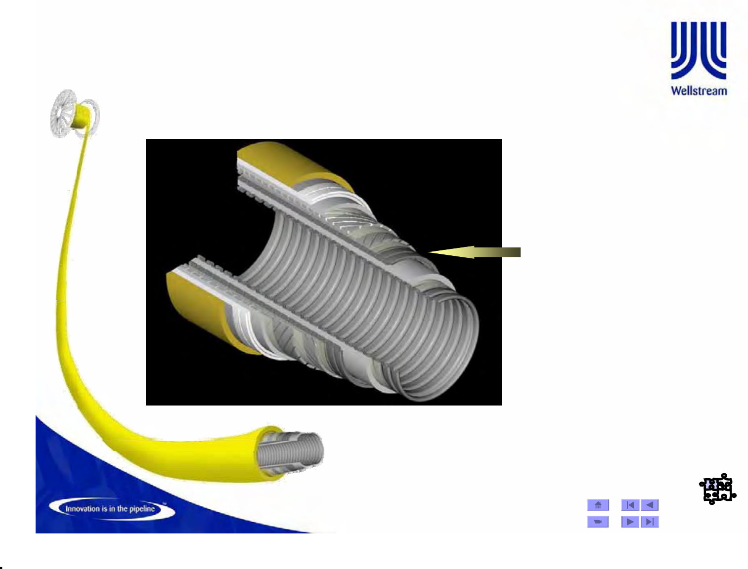
Pressure Armor
•The Flexlok machine applies a
shaped, rolled, carbon steel wire
which is preformed and
interlocked as it is wound around
the pipe, providing a smooth,
flexible, continuous layer to
support the barrier and increase
pipe burst pressure.
•When design and pressure
requirements demand higher burst
strengths, Flexpress, a wide flat
wire, may be wound over the
Flexlok layer.
•Machines that apply from 1 to 4
wires simultaneously are used.
Material Selection
Material Selection
Sweet & Sour Service
© Wellstream International Limited. Duplication in full or in part is prohibited.
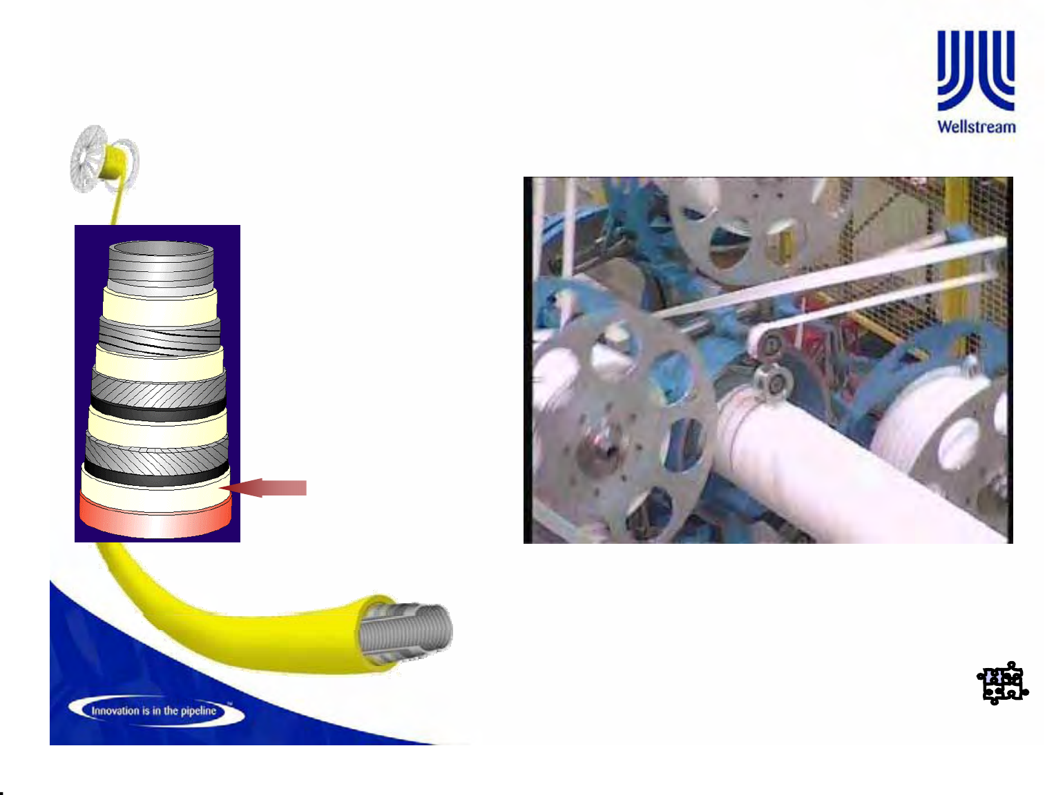
Manufacture -77
Taping Head
¾The tape heads are
suitable for the
application of either two
or four tapes. A
fabricated steel frame
supports the rotating
head.
¾The following tapes are
applied -
–Manufacturing aids
–Anti-birdcaging
(Deepwater)
–Anti-wear
(Dynamic Risers)
–Thermal Insulation
© Wellstream International Limited. Duplication in full or in part is prohibited.
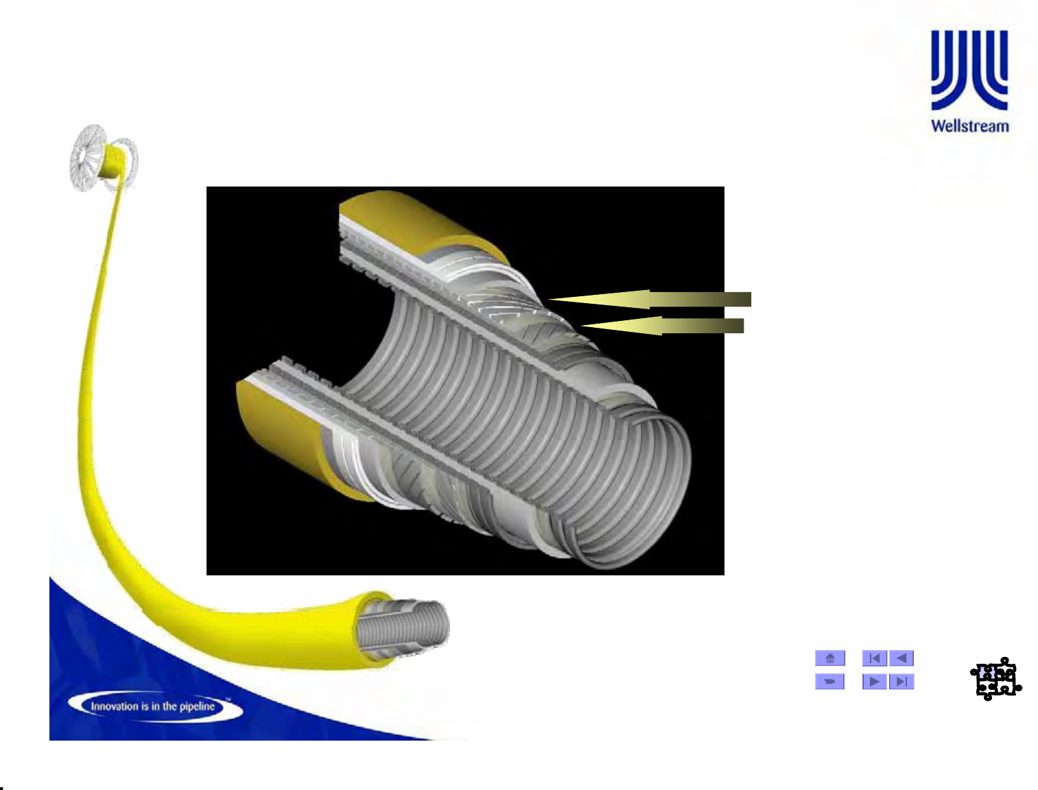
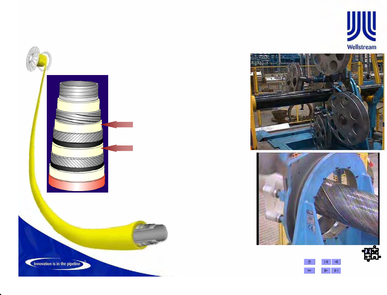
Manufacture -78
Tensile Armour
• The Armour machine applies
a layer of helical steel armour
wires to the pipe.
• The flat wires increase burst
strength and give the pipe
axial strength. There are two
machines that apply the flat
wire contra-helically.
• The flat wire can be of
various sizes and tensile
strengths depending on the
pipe design. As the wire is
applied, it runs through pre-
form tooling heads which
twist the wire so it lays flat
against the pipe’s surface.
Material Selection
Material Selection
Sweet & Sour Service
© Wellstream International Limited. Duplication in full or in part is prohibited.
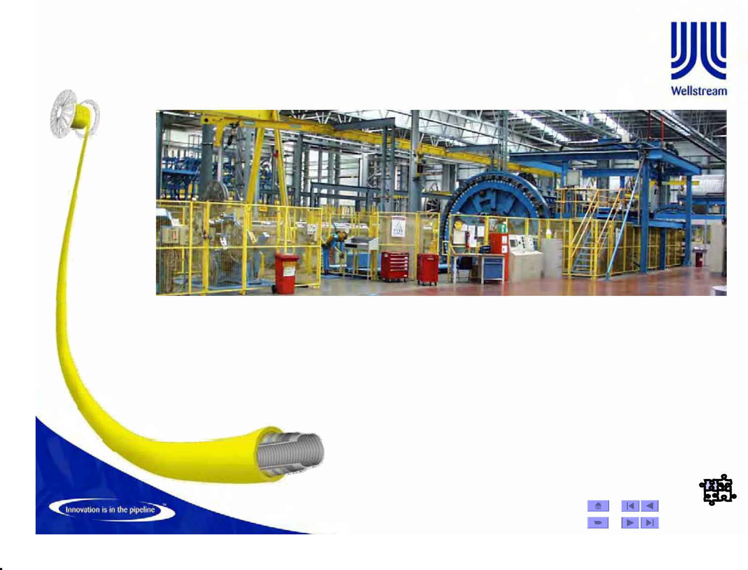
Manufacture -83
Armour Line
¾The armour line consists of two Armoring machines which
rotate in opposite directions from one another.
¾Stationed throughout the line are tape machines which
apply the tape layers.
© Wellstream International Limited. Duplication in full or in part is prohibited.
Insulation
¾Reduce heat loss
from the bore fluids
(in order to
maintain low
viscosity bore fluids
hence high flow
rates).
¾(Application: 1st
layer melt extruded
onto pipe, 2nd
wrapped onto pipe)
Manufacture -89
© Wellstream International Limited. Duplication in full or in part is prohibited.
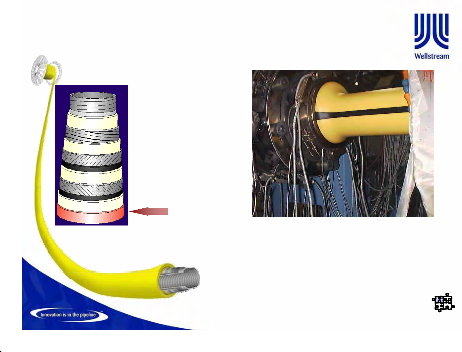
Outer Sheath
Outer Sheath -
-
The Outer Sheath is an
external polymer barrier
applied to resist mechanical
damage and intrusion of
seawater.
Material Selection
Material Selection
HDPE, & PA-11/PA-12
Flexible Pipe Construction
© Wellstream International Limited. Duplication in full or in part is prohibited.
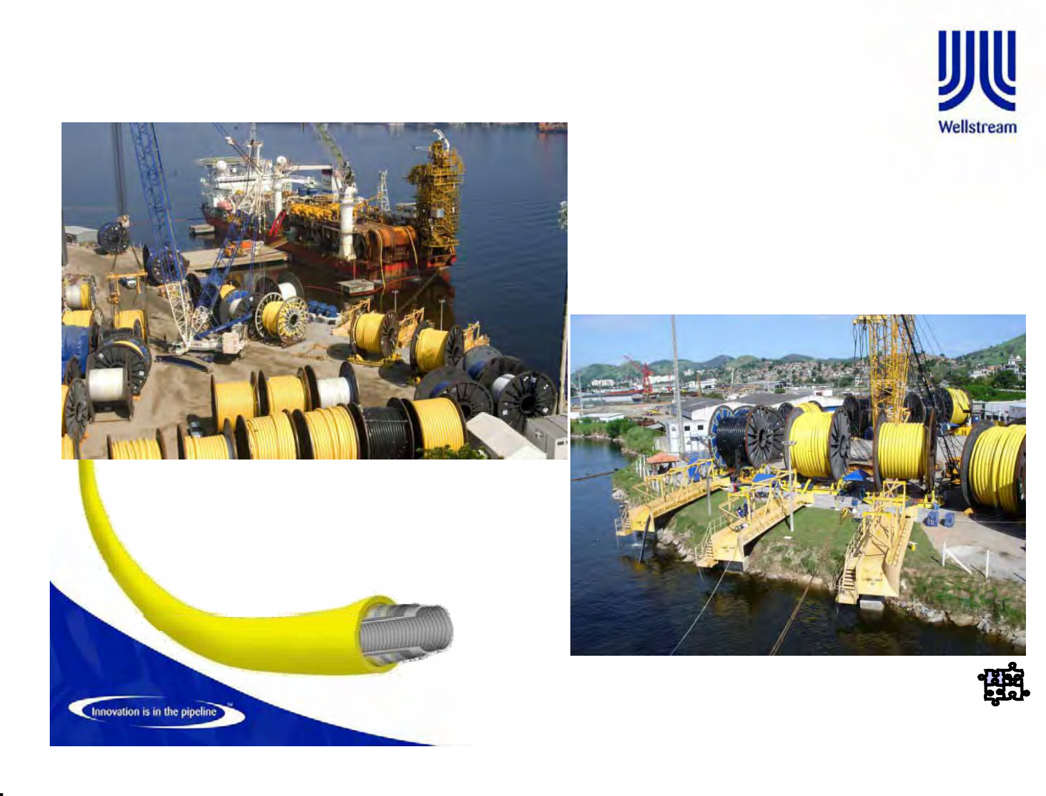
Pipe Completion / Logistic Base in Brazil
© Wellstream International Limited. Duplication in full or in part is prohibited.
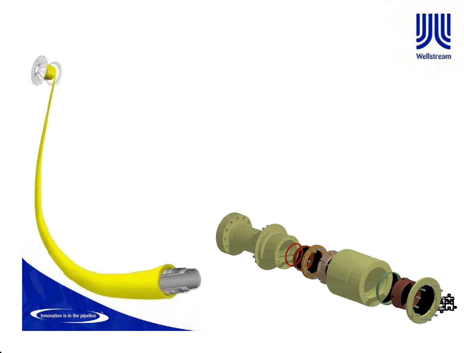
End Fitting Technology
• End fittings are critical components of any flexible pipe system
– Custom designed for each flexible pipe structure
– Each layer of the pipe individually terminated
• Designed to:
– Assure a leak tight transition between subsea and surface facilities
– Withstand severe environmental loads and thermal cycling
– Stronger than pipe in burst and failure tension
– Allow for the venting of permeated gases
• Terminations can be any design - API/ANSI flanges, hubs, welded, or other
• Most common structural material is AISI 4130 low alloy steel
© Wellstream International Limited. Duplication in full or in part is prohibited.
Manufacture -95
Factory Acceptance Tests
•The FAT requirements are specified in the
Fabrication Specification and Quality Plan.
•API 17 J FAT section
–9.2 Gauge Test
–9.3 Hydro Test
–9.4 Electrical Continuity/Resistance
–9.5 Gas Venting Test
© Wellstream International Limited. Duplication in full or in part is prohibited.
•Hydrostatic
– Minimum hydrotest pressure is 1.5 times the design pressure and
the maximum pressure is 1.04 times the minimum hydrotest
pressure
– After the 24 hour period if the pressure has not dropped more than
4% the pipe is considered to have passed hydrotest
Factory Acceptance Testing (FAT)
© Wellstream International Limited. Duplication in full or in part is prohibited.
• Outer Sheath Integrity
– By pressurizing the annulus of the pipe to 30psi maximum for a period of 30
minutes
– The pressure must remain above 20psi during the test period and should
not reduce by more than 1psi during the last 15 minutes of the 30 minute
hold period
Factory Acceptance Testing (FAT)
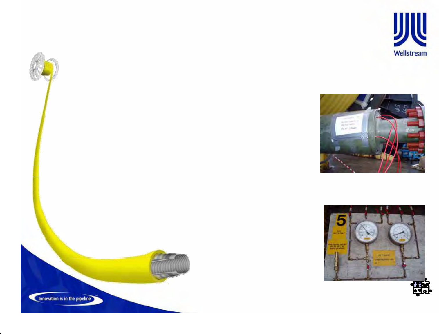
• Pressure relief system test (Annulus gas venting)
– To verify the flow of air through the annulus, over the full length of the pipe
– Hoses are attached to the vent holes at the in-board endfitting then pressure is
introduced slowly to a maximum of 90psi
– Hoses are then attached at the out-board endfitting and the pressure and flow
rate are recorded. A show of air bubbles are also required
© Wellstream International Limited. Duplication in full or in part is prohibited.
• Endfitting testing
– Electrical Resistance - To confirm the insulation from the Barrier
layer/Insulation ring between the Carcass and the Endfitting by
measurement of resistance
– Electrical continuity test – To measure that the resistance between
both endfittings is less than the omhs (:) advised on the
MWO/PWO for the length of pipe tested
Factory Acceptance Testing (FAT)
© Wellstream International Limited. Duplication in full or in part is prohibited.
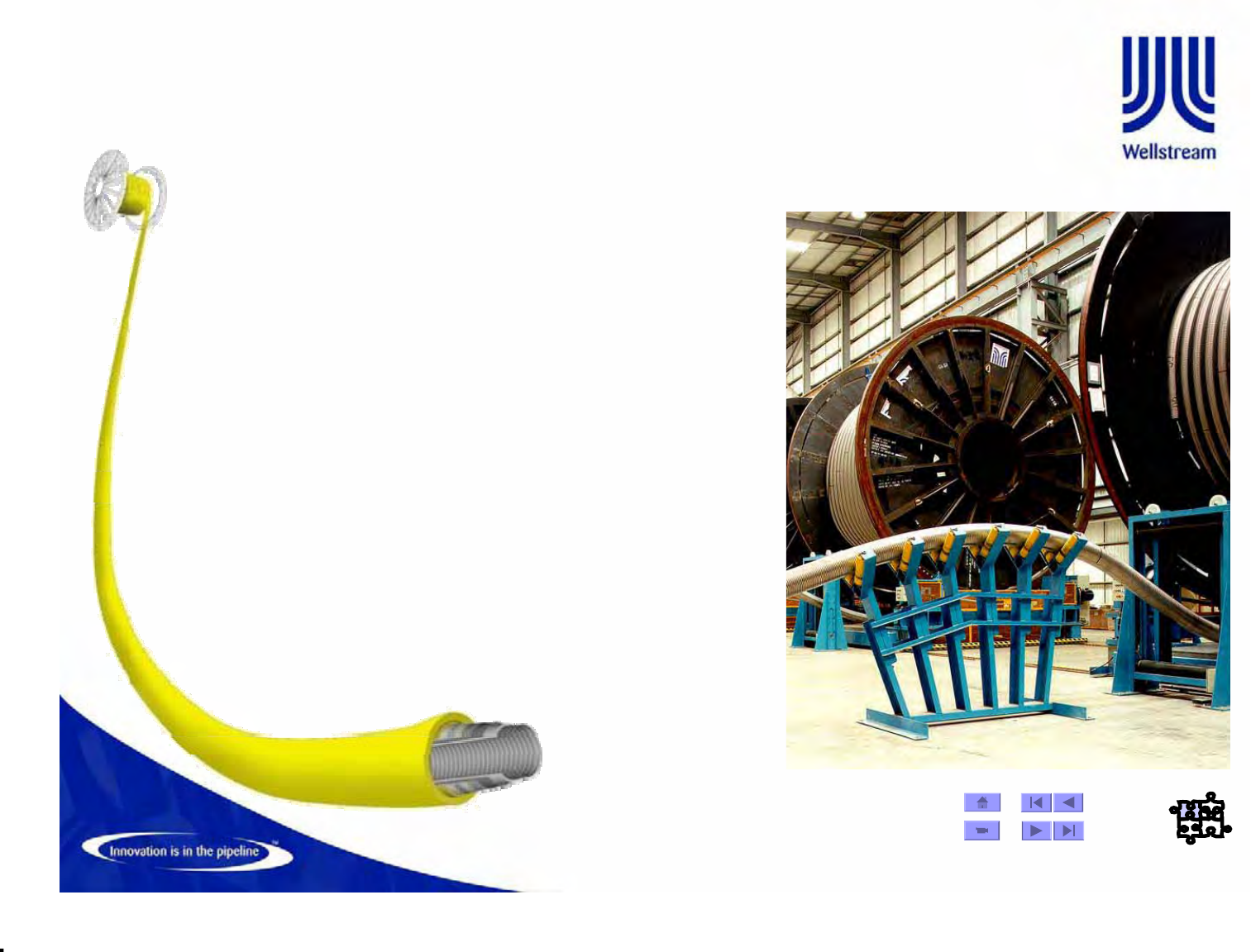
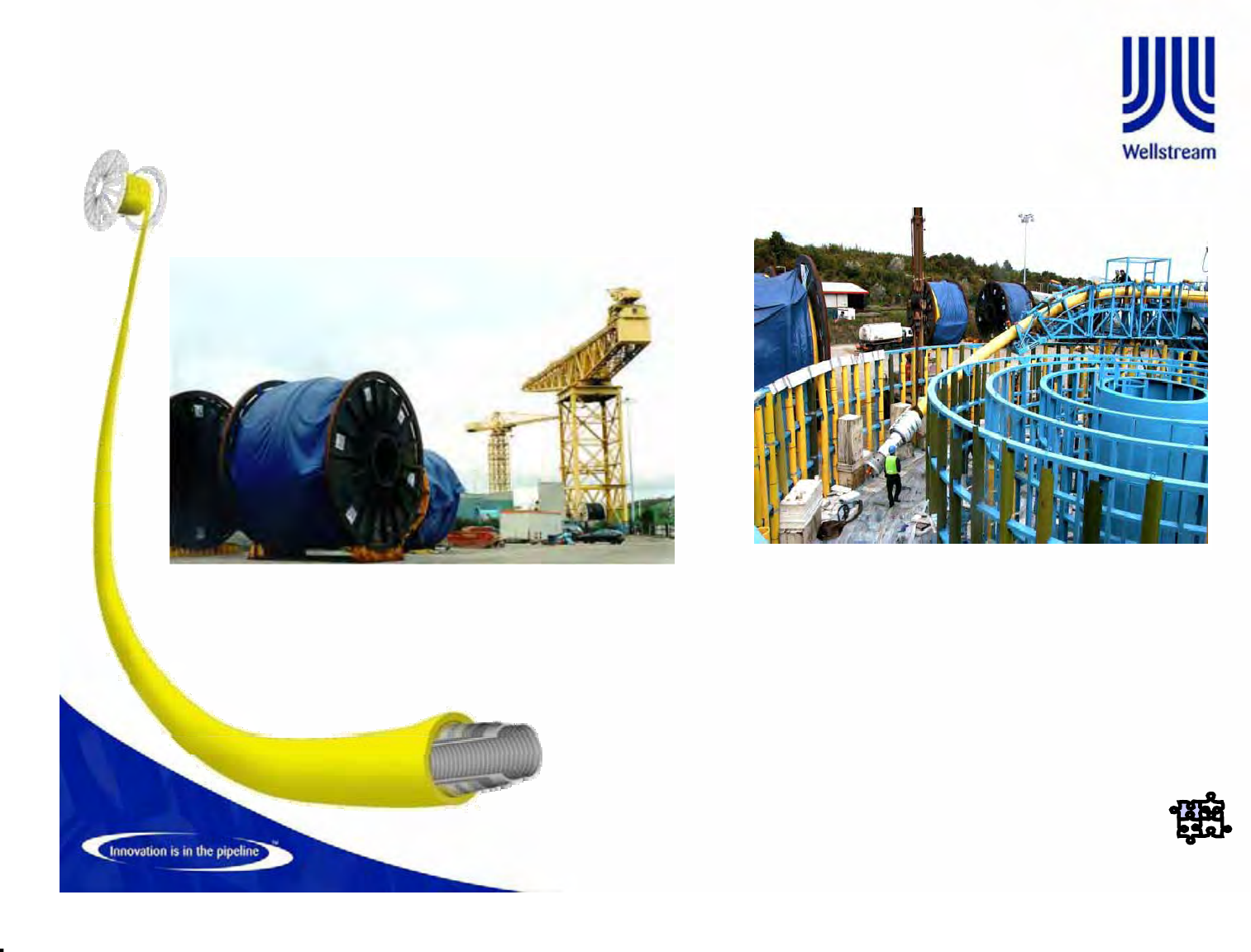
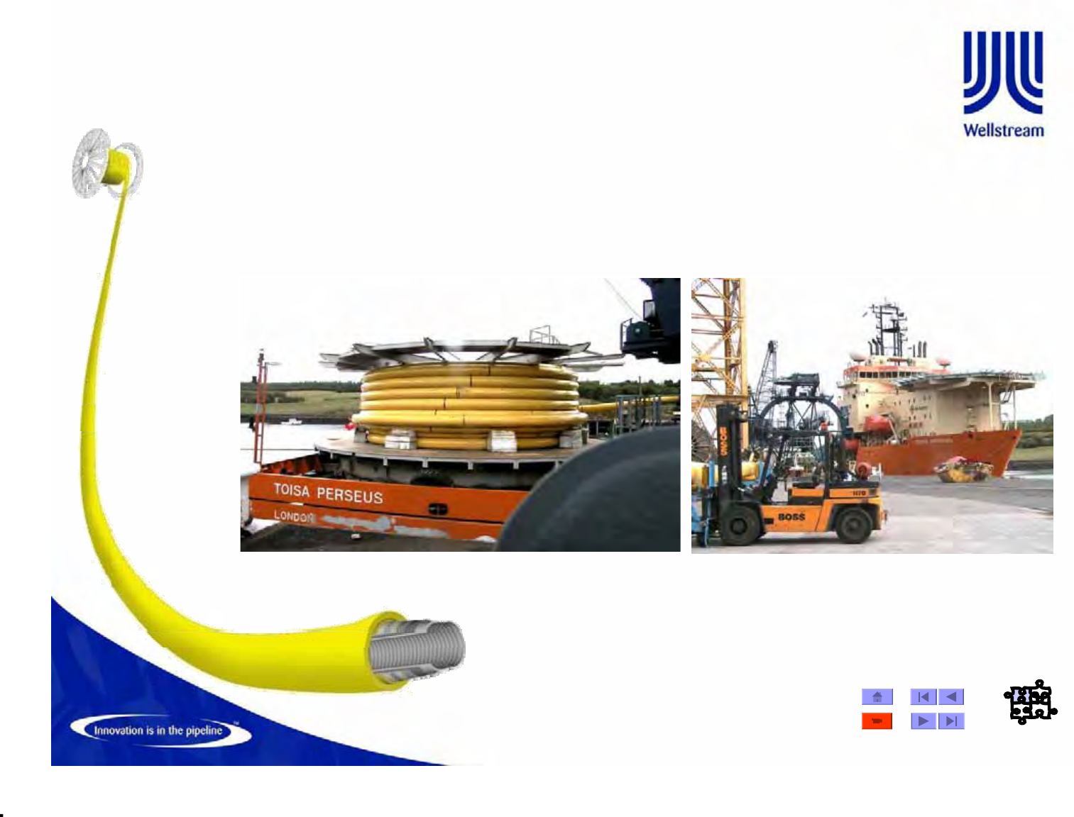
Storage
Storage
Flexible Pipe Construction
• Reel diameters are from 26ft to 35ft, typical way of handling flexible pipe
• Carousels used for very long lengths
© Wellstream International Limited. Duplication in full or in part is prohibited.
Manufacture -99
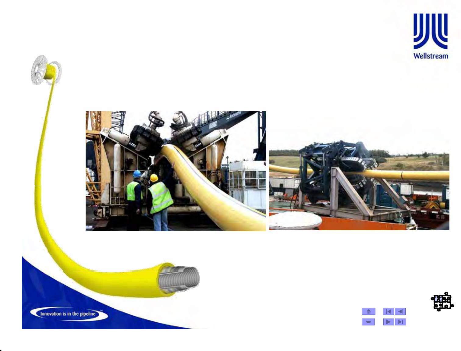
Load-out
¾Once the pipe is
completed it is
secured to a reel
or installed in to a
carousel.
© Wellstream International Limited. Duplication in full or in part is prohibited.
Manufacture -100
Load-out
© Wellstream International Limited. Duplication in full or in part is prohibited.
Flexible Pipe and Umbilical loud-out at Wellstream
Base
© Wellstream International Limited. Duplication in full or in part is prohibited.
Manufacture -102
Load-out
© Wellstream International Limited. Duplication in full or in part is prohibited.
Manufacture -103
Load-out
© Wellstream International Limited. Duplication in full or in part is prohibited.
Qualification Criteria & Scaling Limitations
• Two Objectives to Prototype testing:
– Prove or validate new or unproven pipe designs
– Validate the manufacturers’ design methodology for a new
pipe design
• Scaling of previous test results can be used
– Pressure – the test pipe may be used to qualify pipes of the
same family having equal or lower pressure rating
– Internal Diameter – testing of one pipe of a product family
should verify products two inches larger or smaller than the
size tested
• Scaling comparisons also based on pressure and internal
diameter (P x ID), with the test pipe qualifying pipes with a
lower P x ID value.
© Wellstream International Limited. Duplication in full or in part is prohibited.
Testing Classes
• All Unbonded Flexible Pipe testing is executed in accordance with API Recommended
Practice 17B
• API RP 17B categorizes test types into three classes:
– Class I – basic tests identifying ultimate capacity under simple loading
– Class II – tests verifying specific aspects of a flexible pipes performance
– Class III – tests characterizing the flexible pipe behaviour
– Petrobras NI-2409 A additional Tests as Tension-Tension, DIP Test, etc…
© Wellstream International Limited. Duplication in full or in part is prohibited.
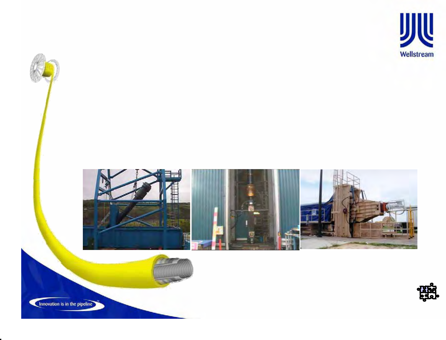
Classification of Prototype Testing
Class II Class III
•Burst
• Tension
•Collapse
•Dynamic Fatigue
•Crush Strength
• Combined Bending & Tension
• Sour Service
•Fire
• Erosion
•DIP TEST – (Bird Cage Test)
• Bending Stiffness
• Axial Stiffness
• Abrasion
• Rapid Decompression
• Axial Compression
•Thermal Characteristics
•Thermal Cycling
• Artic, Weathering
• Structural Damping
Class I
© Wellstream International Limited. Duplication in full or in part is prohibited.
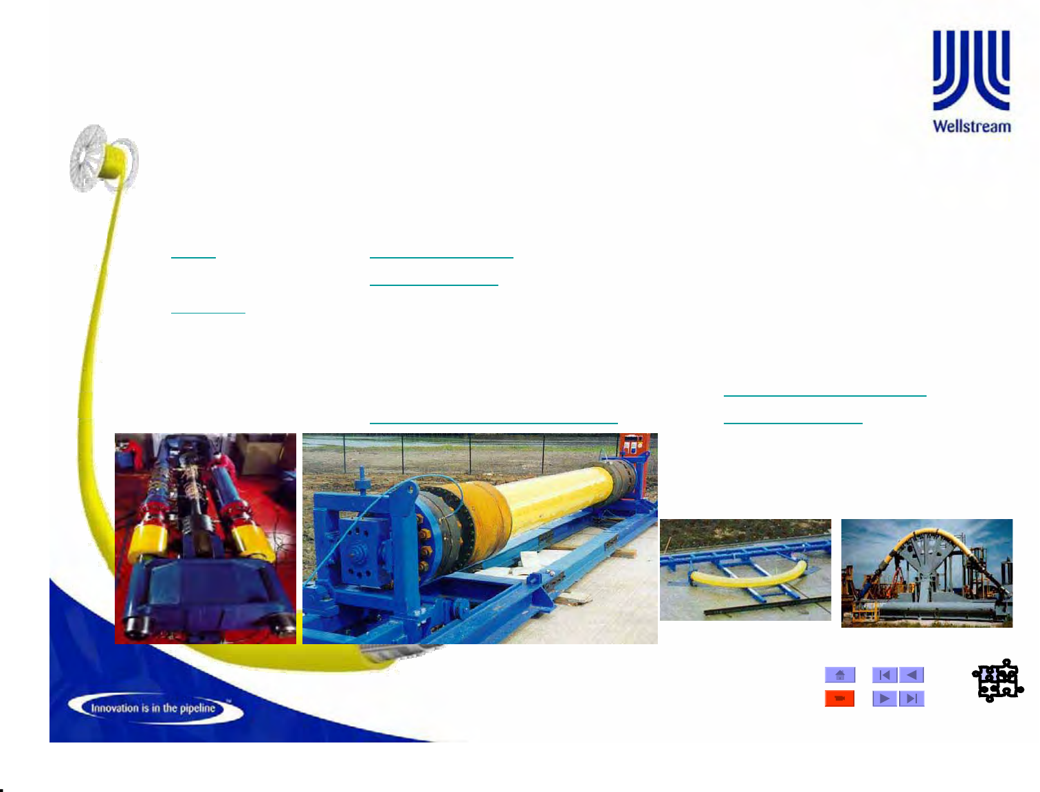
Thermal Cycling
Mid-Scale Thermal Cycle Tests evaluate the
swaging and sealing arrangements under thermal
loading during start-up, shutdowns and changing
properties of the intermediate sheath material over
the service life
Full-Scale Thermal Cycle Test As a minimum 50
thermal cycles at specified max / min temperature for
two samples. Following completion, pipe is dissected for
evidence of barrier slippage
© Wellstream International Limited. Duplication in full or in part is prohibited.
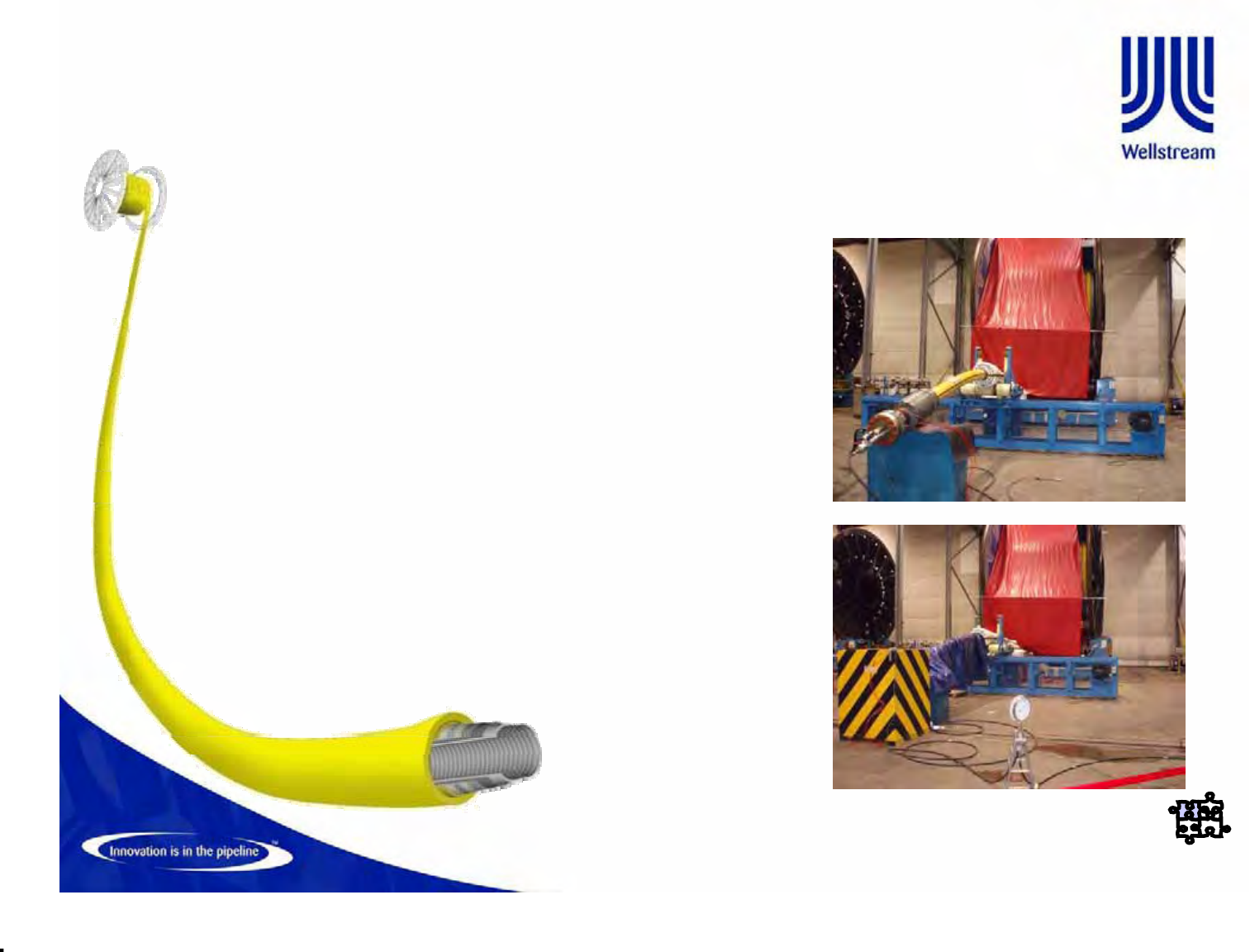
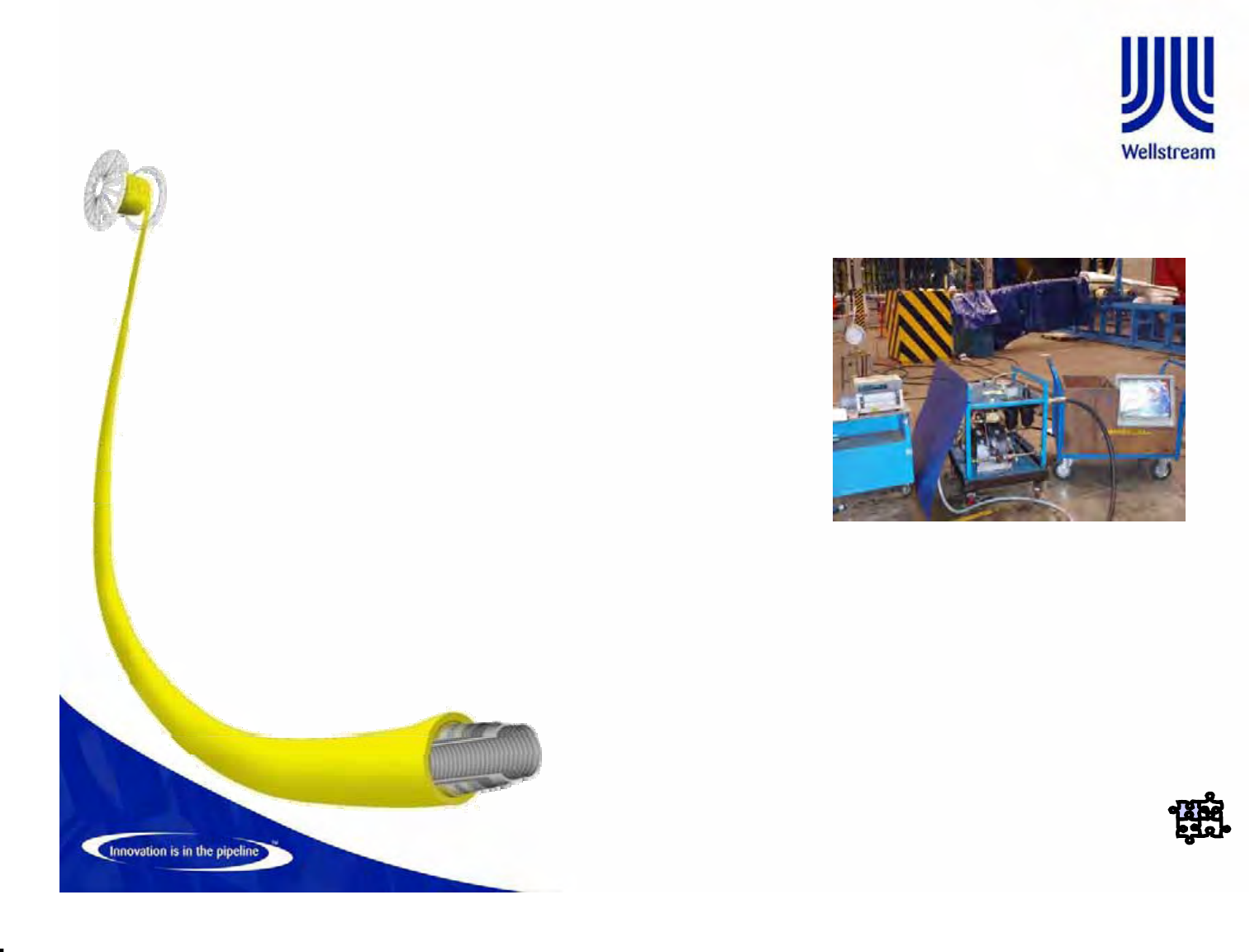
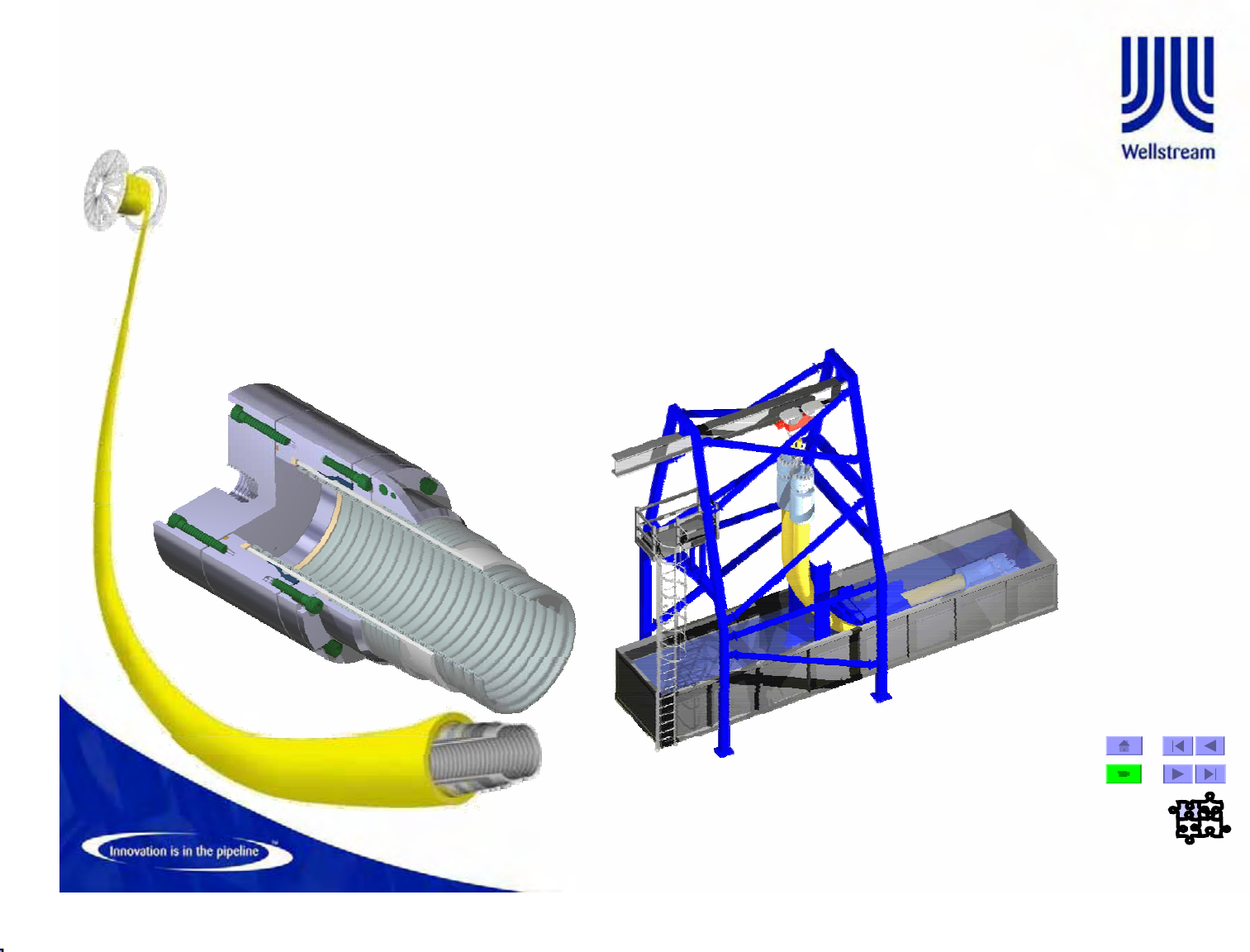
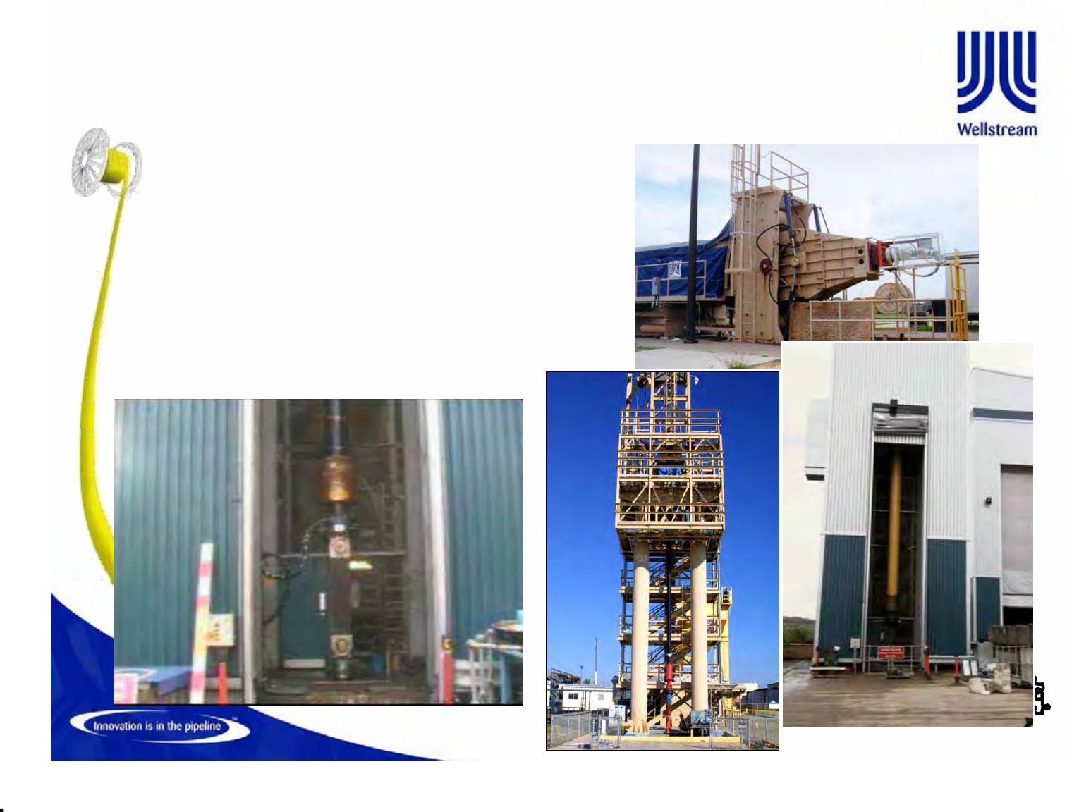
Full-scale Dynamic Fatigue Tests
2M Cycles representing the most
severe operating load cases. Also
the total test fatigue damage is
equivalent to in service fatigue
damage. Bore pressure = MAOP
© Wellstream International Limited. Duplication in full or in part is prohibited.
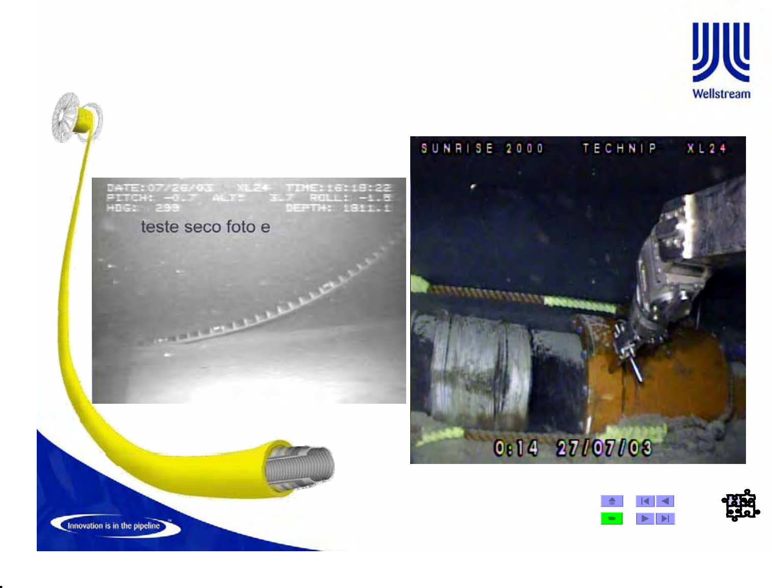
Wellstream Golfinho C240/C272 Field Product Tests
• Deep Immersion Performance Test,
“DIP” test (OFFSHORE)
