Wheelwriter Adaptation Instructions
User Manual:
Open the PDF directly: View PDF ![]() .
.
Page Count: 10
IBM/Lexmark Wheelwriter 1000 Teleprinter Adaptation
https://github.com/IBM-1620/Junior/raw/master/docs/wheelwriter-adaptation-instructions.pdf
The IBM 1620 Jr. project sponsored by the Computer History Museum is recreating the experience of
running historic software on a 1960s-era computer by bringing a real IBM 1620 console to life with a
cycle-accurate simulation running on a modern microcomputer. An integral part of the IBM 1620
console is the attached typewriter used to enter booting instructions and interact with programs. The
typewriters used on the original machines were the IBM Executive Model B and the IBM Selectric,
neither of which is practical to use for the recreation. Instead, a more recent IBM/Lexmark
Wheelwriter 1000 typewriter has been adapted by interposing a microcontroller between the
typewriter’s keyboard and logic board. This allows keys typed on the keyboard to be captured and sent
to the simulator over a USB serial link and, conversely, for the simulator to send characters that are
printed by injecting virtual keypresses to the logic board.
Other historical computer projects may have a similar need for a computer-interfaced typewriter or
teletype and could use the same approach with a variation of the microcontroller firmware. This
document provides instructions for modifying an IBM/Lexmark Wheelwriter 1000 typewriter as was
done for the IBM 1620 Jr. project. These instructions may work with other model Wheelwriters, but
that has not been verified. The tasks include drilling holes in the typewriter case to mount the added
USB Interface Board and USB-B cable; unsoldering two keyboard cable connectors from the
typewriter’s logic board to reuse on the interface board and be replaced by more readily available
connectors; building the USB Interface Board; and installing the interface board and cables connecting
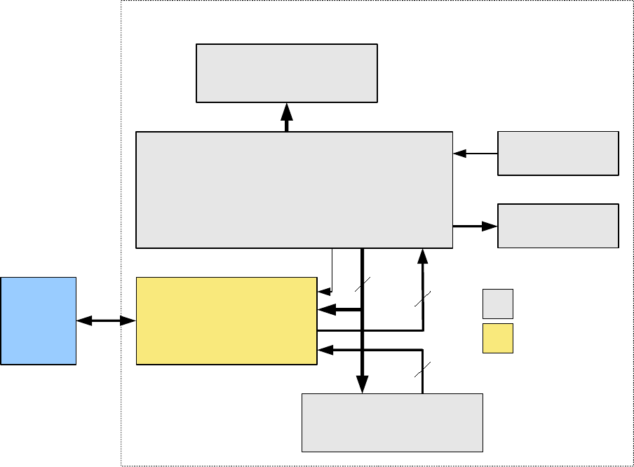
it to the logic board. The following block diagram shows the adaptation.
1 2018-07-24
8
8
Wheelwriter Logic Board
(microprocessor, motor control, keyboard scanning)
Print Mechanisms
(carriage, roller, printwheel)
LED Panel
Power Supply
(+5V, +32V)
Power (+5V)
Column Sync
Keys Out
Keys In
Keyboard
(68-key membrane matrix)
IBM
1620
Jr.
Interface
Board
(microcontroller)
Columns Rows
USB
8
8
14
Modified IBM/Lexmark Wheelwriter 1000
Native Components
Addition
Scan
J13
Read
J14
Wheelwriter Case Modifications
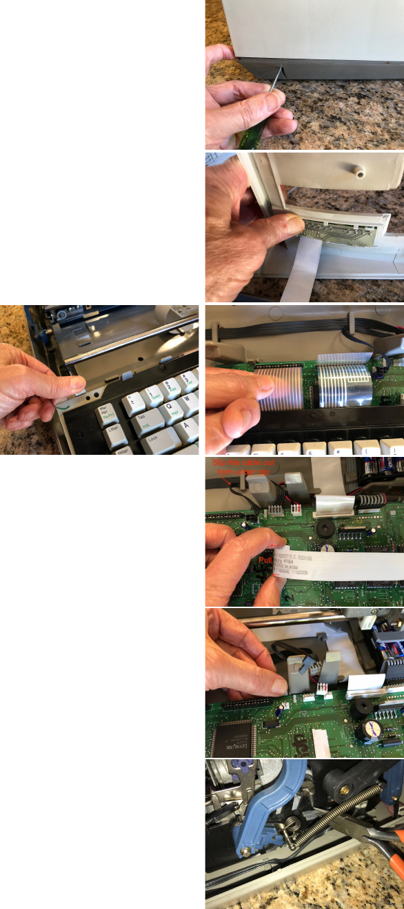
1. Pull the paper release and paper bail load levers forward.
2. Remove the top half of the Wheelwriter case by inserting a thin
screwdriver into the slots in the lower half of the case on each
side near the back and pushing in on the latches to release the top
half, then rotate the top half upwards from the rear. The top will
still be tethered by a cable to the LED display panel.
3. Gently push on the back side of the LED panel to disengage it
from the top half of the case, then feed it back through the hole so
the top half is completely free.
4. Remove the ribbon cartridge by pushing on the blue lever and
then lifting up and out, then manually push the carriage all the
way to the right so it is out of the way.
5. Remove the keyboard from its
mounting by releasing four latches
along the back edge of the
keyboard and then rotating upward
slightly and pulling the keyboard
out from the catches at the front.
Then you can set the keyboard
down and pull the FFC (flat flex
cable) cables out of the logic board connectors.
6. Unplug all the cables connected to the logic board. The
connectors for the two white FFC cables are zero-insertion-force
connectors where you pull on the clamp tabs to release the cable.
All the other connectors lift straight up, but the 8-wire cable J15A
is quite stiff and requires some force to lift. The black two-wire
cable going to J3 needs to be slipped out from under the clip in
the base and rerouted since the USB Interface Board will cover
that clip.
7. Remove the logic board by releasing three latches along the back
edge and lifting it out of the catches at the front.
8. Unplug the connectors from the two servo motors at the back of
the case (for platen rotation and carriage motion).
9. Unplug the two wires from tabs on the switch at the bottom of the
paper bail load lever. It is not necessary to keep track of which
wire was connected to which tab.
2 2018-07-24
10. Push the carriage back to the left and slip the carriage FFC cable
out from under the clip in the center of the case bottom. Insert a
round object such as a center punch or pencil between the two
layers of the carriage FFC cable where it makes a 90° bend in
order to slip the cable out from under the inner clip at that corner,
then slide the cable out from under the outer clip.
11. Remove the whole frame assembly by releasing the four clips at
the corners of the frame assembly. Use a twisting motion with a
large screwdriver on the inside of the sheet metal frame members
(except the right rear which is outside) to pry the latches free from
the slots in the frame while lifting the frame to completely
remove it. The latch has to bend back more than 1/8” before it is
free of the frame.
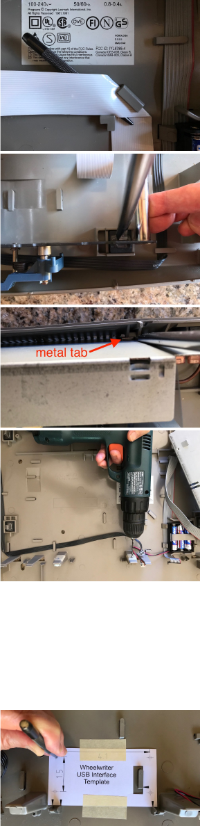
12. Move the power supply out of the way by prying two catches in
the back side of the plastic base away from tabs on back side of
the power supply’s metal case and rotating it out of the way (no
need to unplug the AC connectors). Drill 3/32" holes in the two
keyboard support posts adjacent on both sides of where the USB
Interface Board will go, located 1.35" from the floor of the
Wheelwriter case and centered in the width of each post.
Marking the location on a piece of masking tape and center-
punching with an awl may help. Drill only through the near
surface of the post which is less than 1/8” thick. Snap the power
supply back into place and slip its cable back under the clips in
the base.
13. Slip the platen motor cable that runs along the left side of the base
out from under its clips where it crosses the location where the
USB Interface Board will go in the middle of the base, and fold it back out of the way.
14. Print and cut out the two templates provided on a later page of this document. Verify that the
printer scaling is accurate by measuring the dimensions as shown on the Wheelwriter USB
Interface Template, and reprint with adjusted scaling if necessary.
15. Place a scrap piece of 3/16” plywood or other material underneath
the middle of the base to support it where holes to mount the USB
Interface Board will be drilled. Position the Wheelwriter USB
Interface Template against the reference points indicated by
arrows, and tape in place. Center-punch for the four USB
Interface Board mounting holes indicated on the template. Some
generations of the Wheelwriter 1000 have a thin aluminum static shield covering the base which
is not present on the unit in these photographs, but the procedure is the same. Drill 1/8"
mounting holes from the top.
16. From the underside of the case, countersink the four mounting holes for the USB Interface
Board standoffs so the flat-head screws will be below the surface.
3 2018-07-24
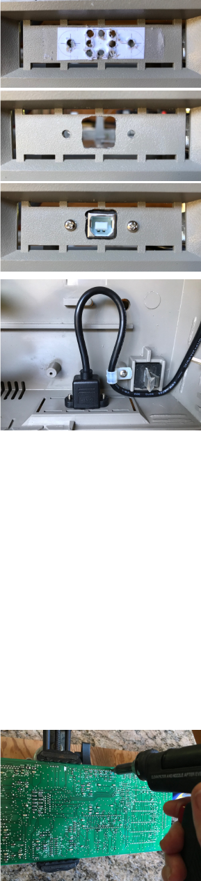
17. The second template shows the cutout pattern for the USB-B
connector. Use double-sided tape to attach it centered on the
knockout panel in the rear of the lower case (on the right as
viewed from the rear). Use an awl to center-punch for the
mounting screw holes and holes at the corners and midpoints of
the center cutout area, then drill 1/8" holes for the mounting
screws, corners and midpoints. Clear out the cutout with snips,
saw, file, razor knife and/or Dremel tool.
18. Install the USB panel-mount connector using the provided
screws.
19. Restrain the USB cable with a cable clamp screwed to the left
post inside the knockout panel area using one of the #4 truss head
sheet metal screws.
20. Set the frame assembly loosely back in position making sure not
to pinch any cables.
21. Connect the two wires to the tabs on the switch at the bottom of
the paper bail load lever. It does not matter which wire goes to which tab.
22. Slide the carriage FFC cable back into the corner clips so the bottom layer is under the inner
corner clip and then the fold slides into the outer corner clip. Then insert the round object to
bow up the upper layer to get it uder the inner corner clip. Also slide the cable back under the
clip in the center of its track.
23. Push the frame assembly back down into its four corner latches.
24. Plug in the cables for the two servo motors at the back.
25. Slip the platen motor cable back under its clips where it will cross under the USB Interface
Board.
Logic Board Modifications
1. Unsolder the keyboard FFC connectors (TE/AMP part 6-520315-
5) from logic board to reuse on the USB Interface Board. This is
most easily done with a vacuum desoldering tool, but may also be
possible with a hand solder-sucker or solder wick. Another
approach is to solder a piece of 10-14AWG solid wire across all
the pins of the connector, then heat that wire with enough power
so that all the pins are melted at once to pull out the connector.
2. Remove solder from the leftmost 3 holes of unpopulated J9 on the logic board (in the right rear
corner).
4 2018-07-24
3. Install new 6-103908-4 FFC connectors on the logic board in J13
and J14 with latches toward the edge of the board.
4. Install a 22-27-2031 3-pin Molex connector in J9 on logic board,
with the latch away from the edge of the board.
5. (optional) Clean soldered areas with solvent to remove flux.
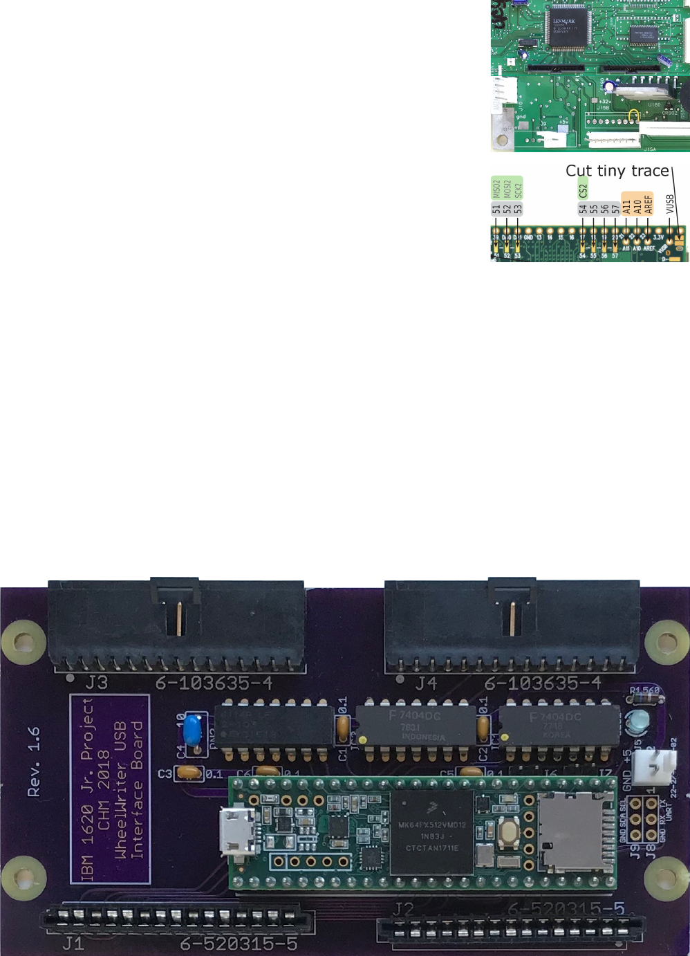
USB Interface Printed Circuit Board Assembly
1. Cut the VIN - VUSB trace on the underside of the Teensy board.
2. Insert SIL header pins into the 48-pin socket, then set the Teensy
board over the pins to solder.
3. Insert and solder two new 6-103635-4 FFC connectors and the two 6-520315-5 FFC connectors
harvested from the logic board.
4. Insert and solder a 22-27-2021 2-pin power connector with the latch side toward the edge of the
board.
5. Insert and solder the discrete components (capacitors, resistor, LED).
6. Insert the three DIPs (two 7404 ICs and the resistor array) using a pin-squeezing tool, then
solder them.
7. Insert and solder the two 2-pin headers J6 and J7.
8. Insert and solder the Teensy socket (possibly with the Teensy in place).
9. Clip all component leads on the back side of the board to avoid damaging FFC cables.
10. (optional) Clean with solvent to remove flux.
5 2018-07-24
Install the USB Interface Board and Cables
1. Attach four standoffs for mounting the USB Interface Board using flat-head screws from the
underside, but don't tighten them.
2. Reinstall the logic board but do not attach any cables yet.
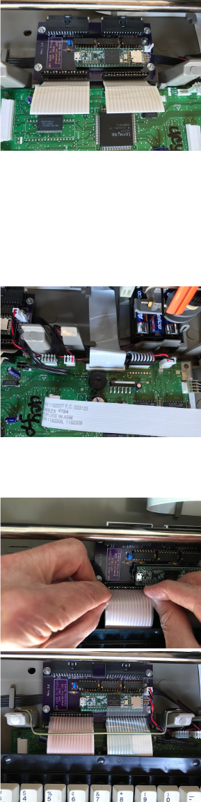
3. Plug FFC interconnect cables into USB Interface Board and fold
them back under the board right at the connectors. Plug the other
end of the FFC interconnect cables into the logic board.
4. Install the USB Interface Board onto standoffs with washers and nuts. Finish tightening using a
wrench or nutdriver on the nuts and tighten the screws from underneath.
5. Where the FFC interconnect cables come up from under the USB Interface Board by the logic
board, pull the cables taut and fold them away from the USB Interface Board right at the
connectors on the logic board, then crease the excess so they will stay under the keyboard.
6. Install the new power cable from the logic board to the USB
Interface Board, routing it underneath all the other cables along
the back edge of the logic board. Bend the wires down sharply at
the connector on the USB Interface Board to avoid interference
with the carriage. Now reconnect all the existing cables. To
insert the FFC cables for the carriage and the LED panel, first pull
the connector clamp open, then insert the cable, then push the
clamp closed. The black 2-wire ribbon cable to J3 has excess
length now because it no longer hooks through the clip that is now under the USB Interface
Board, so bend that excess over the logic board.
7. Lay the keyboard loosely over its position and insert the FFC
cables from the keyboard into the connectors on the USB
Interface Board (this is not easy – it may require padded forceps).
8. Make a bracket to depress the keyboard FFC cables by manually
bending steel coat-hanger wire using needle-nose pliers according
to the dimensions shown in the CAD diagram below.
9. Install the bracket to hold back the keyboard FFC cables using
two #4 truss head screws into the holes drilled into the keyboard
support posts.
10. Install the keyboard into its front catches and then rear clips.
11. Plug in the micro-USB connector into the Teensy.
12. Adjust the position of the USB cable, wedging it down behind the left rear foot and restraining
it with a cable tie to the existing clip for the platen motor ribbon cable at its front corner.
6 2018-07-24
13. Plug in and power on the Wheelwriter. Plug a USB-B into the cable into the new panel
connector at the back of the Wheelwriter and connect it to the host computer, then download
appropriate firmware into the Teensy. It will be necessary to cycle power on the Wheelwriter
after the download before the logic board will be properly operating with the firmware on the
USB Interface Board.
14. Verify operation with appropriate test programs.
15. Reinstall the top half of the Wheelwriter case: pull the paper release and paper bale levers
forward; thread the LED panel through its hole in the case top; hook in the catches at the front
of the machine and then tilt down the back until the latches meet and catch; and finally snap the
LED panel back into place.
7 2018-07-24

Count Description Source Source PN Cost Note
1 USB Interface PCB OSHPark 17.42 1
1 Teensy 3.5 without pins PJRC 27.36 2
2 32 SIL header pins for Teensy 952-2521-ND 11.75 2
1 48-pin socket for Teensy ED3648-ND 3.84 2
2 7404 IC 296-14642-5-ND 4.04
1 10K x 13 resistor network 4114R-2-103LF-ND 1.12
5 C320C104K5R5TA 1.10
1 RDEC71H106K3K1H03B 1.05
1 3mm LED (blue) 67-1748-ND 1.78 3
1 CF18JT560RCT-ND 0.10 3
2 TE/AMP 6-520315-5 FFC connector 4
2 TE/AMP 6-103635-4 FFC connector A33887-ND 5.16
2 TE/AMP 6-103908-4 FFC connector A33916-ND 5.80
2 6” Flex cable A9CCA-1506F-ND 17.58
1 Molex 22-27-2021 2-pin connector M WM4111-ND 0.25
1 Molex 22-01-3027 2-pin housing F WM2000-ND 0.12
1 Molex 22-27-2031 3-pin connector M WM4112-ND 0.35
1 Molex 22-01-3027 3-pin housing F WM2001-ND 0.18
4 Molex 08-50-0114 female pins tin WM1114-ND 0.78
2 1x2 header for J6 & J7 jumper 732-5315-ND 0.26
4 3/16 x 3/8 female-male standoff 1772-2032-ND 4.20
4 0.28” diameter flat washer for #4-40 36-4692-ND 0.33
4 Hex nut 3/16” #4-40 36-4694-ND 0.30
4 #4-40 3/8” flat-head screw, phillips Bolt Depot 3717 0.20
3 Self-tapping screws to hold bracket Bolt Depot 7754 0.15
1 Bracket to depress keyboard cables coat hanger wire 5
1 USB cable B panel to micro male, 24” DataPro 1581-02C 10.95
1 Cable clamp for USB cable RP325-ND 0.10
1 Cable tie 298-1017-ND 0.05
2 Hookup wire, red & black 24AWG, 8” A2924R-100-ND 0.70 6
Notes: 117.02 7
1 Minimum order from OSHPark is three boards.
2 Alternatively use Teensy 3.5 with pins plus two 24x1 sockets from PJRC.
3 Any LED color may be used, but may need higher resistance due to lower junction voltage.
4
5
6 Minimum order is 100’ roll. Any hookup wire can be substituted.
7 Shipping cost and taxes not included.
Tools Required
phillips #0 and #1 screwdrivers desoldering tool or solder wick
large straight screwdriver soldering iron with fine tip
3/16” nut driver electric drill
needle-nose pliers (may need two) 3/32”, 1/8” and countersink drill bits
diagonal cutters to clip PCB leads Dremel tool with cylindrical bit, or file
center punch and small hammer
awl or ice pick masking tape
IC insertion tool (optional) double-stick tape
scrap piece of 3/16” plywood or alternative
DigiKey
DigiKey
DigiKey
DigiKey
0.1 µF capacitor DigiKey
10 µF capacitor DigiKey
DigiKey
560 Ω 1/8W resistor DigiKey
Wheelwriter
DigiKey
DigiKey
DigiKey
DigiKey
DigiKey
DigiKey
DigiKey
DigiKey
DigiKey
DigiKey
DigiKey
DigiKey
DigiKey
DigiKey
DigiKey
These connectors are unsoldered from the Wheelwriter logic board.
Bend steel coat-hanger wire (0.07” dia.) using needle-nose pliers to form bracket per CAD diagram.
Xacto knife to cut Teensy trace
Parts List
8 2018-07-24
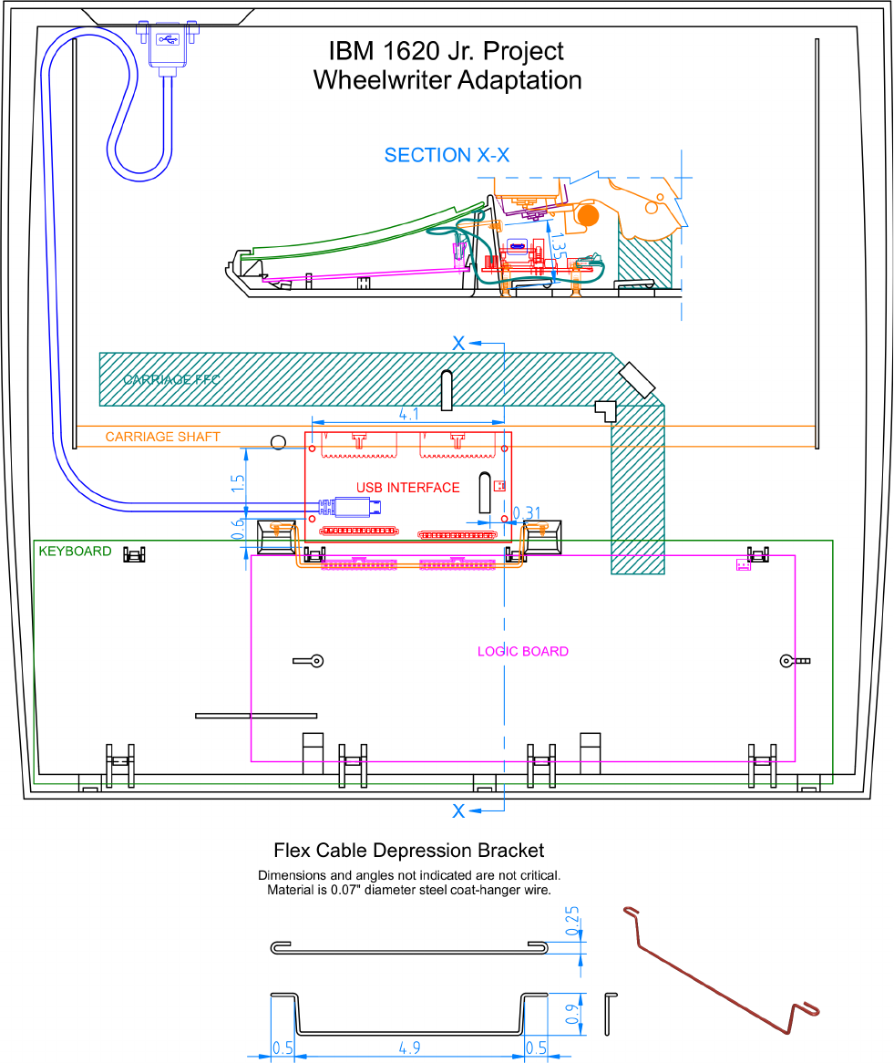
Modified Wheelwriter CAD Diagram
To see details more clearly, try viewing the PDF file for this document online and zoom in. Better yet,
view the original PDF of this diagram with black background that is downloadable from:
https://github.com/IBM-1620/Junior/raw/master/docs/wheelwriter-adaptation-CAD.pdf
9 2018-07-24
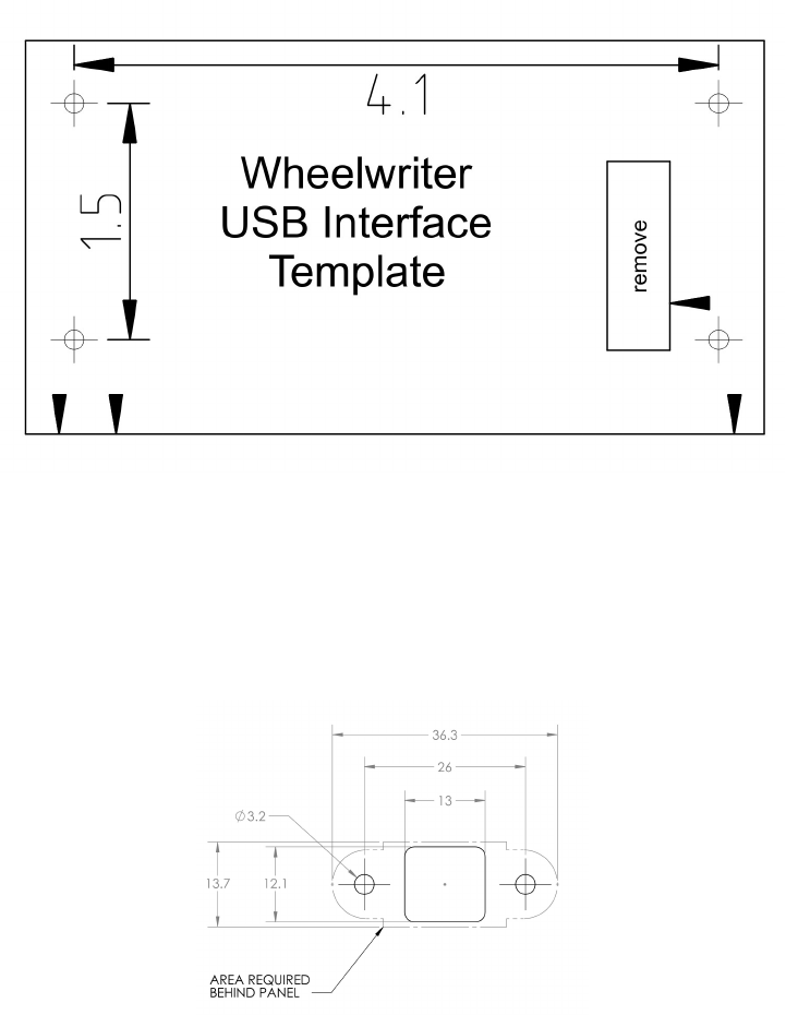
Templates
Print and cut out these templates for use during the Wheelwriter modification procedures. Verify that
the printer scaling is accurate by measuring the dimensions (in inches) as shown on the Wheelwriter
USB Interface Template.
This second template is for drilling and cutting holes in the knockout panel at the rear of the
Wheelwriter base for mounting the USB-B cable. The dimensions are in millimeters, so the 26 mm
distance between the two mounting holes is 1.024 inches.
10 2018-07-24
