Wiegand Readers Reader Manuals
User Manual: wiegand reader manuals
Open the PDF directly: View PDF ![]() .
.
Page Count: 12
MODEL NUMBER:
WPR900-1-0-GB-XX WMR900-1-0-GB-XX
WPK900-1-0-GB-XX WMK900-1-0-GB-XX
WDP900-1-0-GB-XX WKM900-1-0-GB-XX
WIEGAND READERS
Wiegand 125 kHz Passive Proximity Readers
INSTALLATION MANUAL
SPECIFICATIONS
Read Capability ............................
Slim Tags, Omega Tags, Impro Trinary Tags
and HID 125 kHz Tags.
NOTE: HID is a registered trademark of HID Global Corporation (an ASSA ABLOY
Group Brand).
Working Environment
WPR900 and WPK900 ..................
Designed to work in indoor or outdoor
environments similar to IP53.
WMR900 and WMK900 .................
Designed to work in harsh (industrial) indoor or
outdoor environments similar to IP53.
WDP900 ........................................
TBA.
WKM900 ........................................
Designed to work in an indoor or outdoor
environment similar to IP42.
Input Voltage ................................
5 V DC or 12 V DC, polarity sensitive.
Power Requirements
Current (mA)
Power (W)
Supply voltage 5 V DC all
indicators on ...........................
50
0.25
Supply voltage 12 V DC all
indicators on ...........................
50
0.60
Wiegand Bus
Electrical Interface ..................
„0‟ and „1‟ Data streams.
Data Format ...........................
Tag information: 44-bit or 26-bit Wiegand.
Key information: 26-bit Wiegand only.
Inputs
Quantity ..................................
4
Type .......................................
Dry Contact.
Function .................................
Operation of the Buzzer, LED and Scanner
Inhibit.
Buzzer ...........................................
4 kHz piezo-electric single volume, single tone.
Status Indicators
Status LED .............................
Tri-coloured Red, Green or Amber (externally
visible).

WPR300-0-0-GB-02
October 2008
Page 2
WPK900, WMK900 and WKM900 models only
Keypad
Keys (WPK900 and
WMK900). ..............................
12 Alphanumeric keys
Keys (WKM900) .....................
12 Numeric keys and 1 Bell Button.
PIN-codes .....................................
5 Digit codes in the range 00000 to 65535.
4 Digit codes in the range 0000# to 9999#.
INSTALLATION INFORMATION
Accessories
Find the following when unpacking the Wiegand Reader:
WPR900 and WPK900
Either a Wiegand Plastic Non-keypad Reader (WPR900-1-0-GB-XX) housed in a
dark grey, ABS plastic housing. The Wiegand Reader consists of a Front Cover
and a Backing Plate (the Backing Plate is attached with a Self-tapping Screw (M3 x
8 mm)).
Or a Wiegand Plastic Keypad Reader (WPK900-1-0-GB-XX) housed in a dark
grey, ABS plastic housing. The Wiegand Reader consists of a Front Cover and a
Backing Plate (the Backing Plate is attached with a Self-tapping Screw (M3 x 8
mm)).
One 2-Way Programming Pin.
Four Brass Wood Screws (3.5 mm x 25 mm).
Four Wall Plugs (7 mm).
An extra Serial Number Label.
WMR900 and WMK900
Either A Wiegand Metal Non-Keypad Reader (WMR900-1-0-GB-XX) housed in a
Zinc alloy die-cast housing. The Wiegand Reader consists of a Front Cover and a
Backing Plate (the Backing Plate is attached with a Hexagonal Screw (M3 x 8
mm)).
Or a Wiegand Metal Keypad Reader (WMK900-1-0-GB-XX) housed in a Zinc alloy
die-cast housing. The Wiegand Reader consists of a Front Cover and a Backing
Plate (the Backing Plate is attached with a Hexagonal Screw (M3 x 8 mm)).
An Allen Key (2 mm) (WMR900-1-0-GB-XX and WMK900-1-0-GB-XX models
only).
One 2-Way Programming Pin.
Four Brass Wood Screws (3.5 mm x 25 mm).
Four Wall Plugs (7 mm).
An extra Serial Number Label.

WPR300-0-0-GB-02
October 2008
Page 3
WDP900
A Wiegand Door Entry Panel (WDP900-1-0-GB-XX) housed in a Black, ABS
Plastic housing.
One 2-way Programming Pin.
An extra Serial Number Label.
WKM900
A Wiegand Keypad Mullion Reader (WKM900-1-GB-XX) housed in a Black, ABS
Plastic housing. The Wiegand Reader consists of a Front Cover and a Mounting
Bracket (the Mounting Bracket is attached with a Self-tapping Screw (M2 x 6 mm)).
A 1 m Wiegand Connector Cable.
One 2-Way Programming Pin.
Two Counter-sunk Self-tapping Screws (M2 x 6 mm).
Two Counter-sunk Self-taping Screws (2. Mm x 25 mm).
Two Wall Plugs (5 mm).
An extra Serial Number Label.
General
Remember the following when installing the Wiegand Readers:
Maximum Data Communications Distance
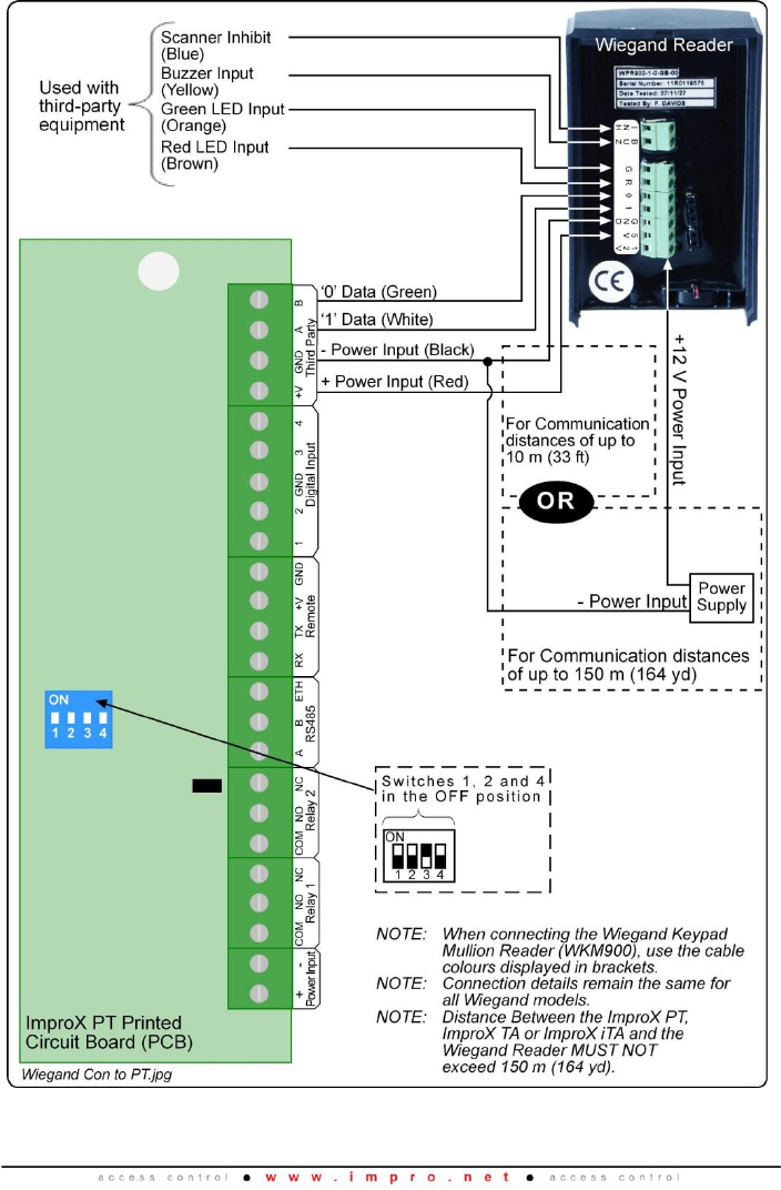
CAUTION: When implementing the 150 m cable distances with the Wiegand
Readers use the 12 V power input option.
Install the Wiegand Readers no further than 150 m (164 yd) from the Host unit. The
cable individual conductor cross-sectional area should not be less than 0.2 mm2
(0.0003 in2).
Distance between Wiegand Readers
To avoid mutual interference, install the Wiegand Readers no closer than 500 mm (20
in) apart.
Mounting the Wiegand Readers
CAUTION: Make certain that you mount the Readers on a vibration-free
surface.
Select the mounting position of the Wiegand Readers, considering accessibility, routing
of wires and visibility of the externally visible LED.
Secure the Wiegand Readers to the mounting surface, using four suitable screws and
wall plugs (supplied), nuts and bolts or rivets.
NOTE: The Wiegand Door Entry Panel is designed for mounting in a user supplied
enclosure. The Reader has 4 mounting holes, drilled to 4 mm in diameter.
The mounting holes accommodate M3 bolts and nuts.
WPR300-0-0-GB-02
October 2008
Page 5
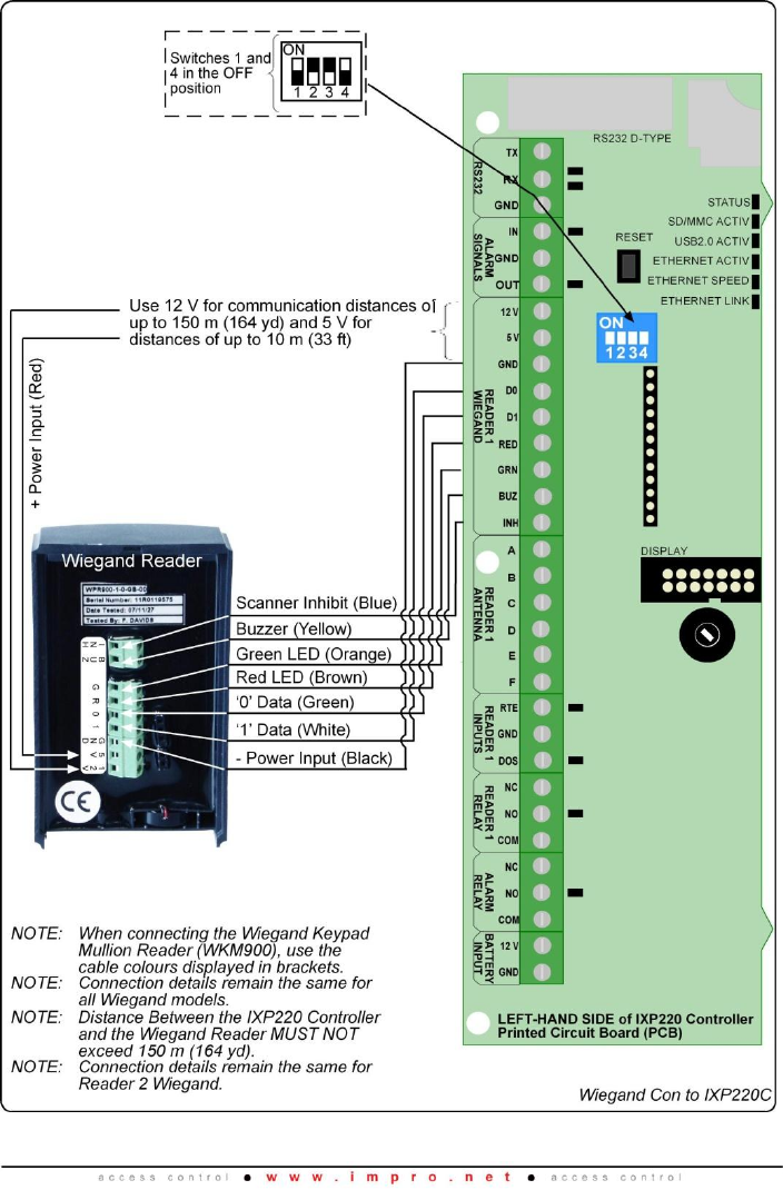
Figure 2: Wiegand Reader Connected to the IXP220 Controller
WPR300-0-0-GB-02
October 2008
Page 6
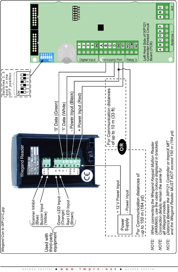
Figure 3: Wiegand Reader Connected to the IXP121 Controller or ImproX MfT
WPR300-0-0-GB-02
October 2008
Page 7
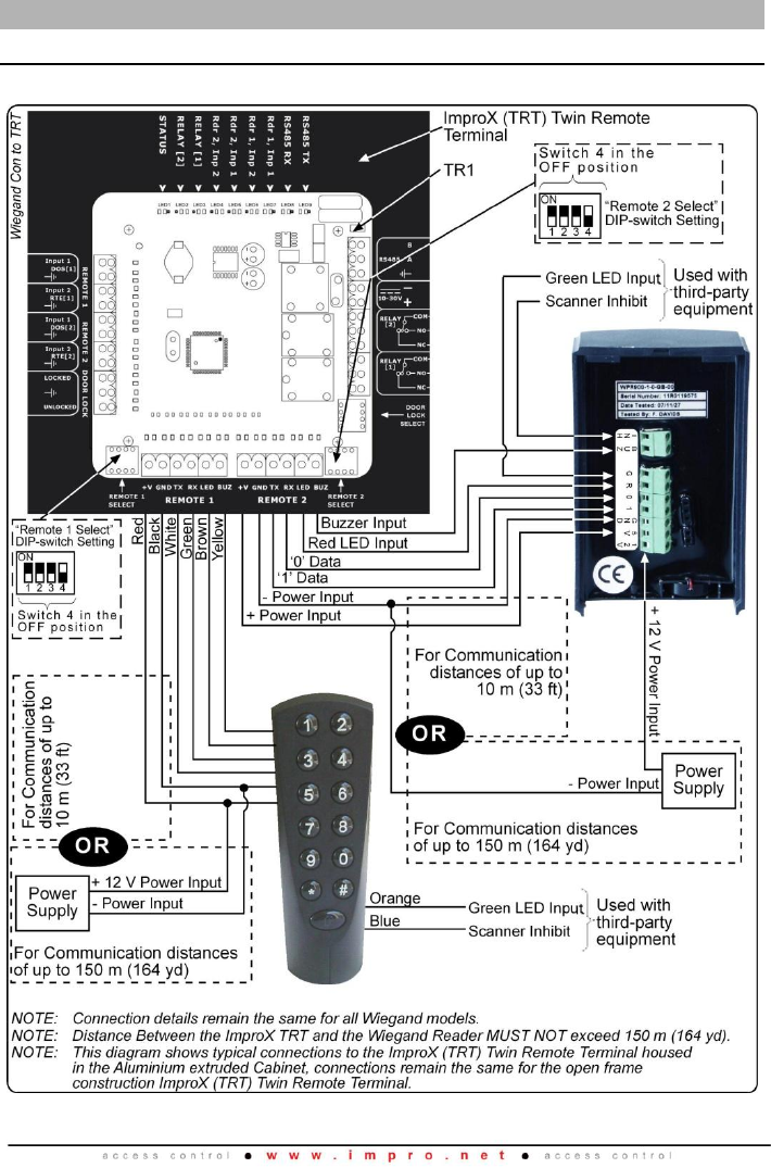
Figure 4: Wiegand Reader Connected to the ImproX PT, ImproX TA or ImproX iTA
WPR300-0-0-GB-02
October 2008
Page 8
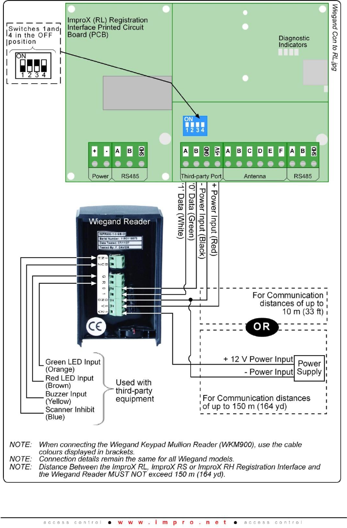
Figure 5: Wiegand Reader Connected to the ImproX RL (ImproX RS and
ImproX RH)
WPR300-0-0-GB-02
October 2008
Page 9
Setting the Wiegand Mode
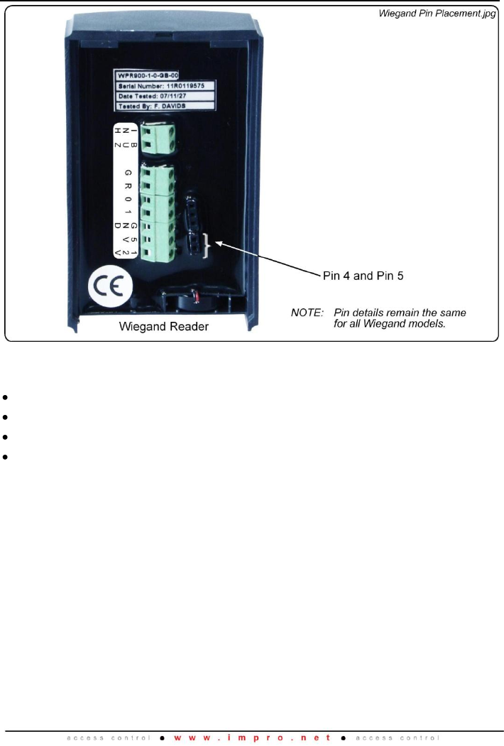
Figure 6: Wiegand Pin Placement
The Wiegand Readers offer four different Output Mode Combinations:
Mode 1 (1 Beep): 26-bit, HID Normal.
Mode 2 (2 Beeps): 44-bit, HID Normal.
Mode 3 (3 Beeps): 26-bit, HID Raw.
Mode 4 (4 Beeps): 44-bit, HID Raw.
The 26-bit and the 44-bit refer to the output format of EMM and Impro Trinary Tags.
HID Tags output in either normal or 45-bit raw mode.
Blank Space
WPR300-0-0-GB-02
October 2008
Page 10
The Output Mode can be selected by doing the following:
1. Remove the Backing Plate from the Wiegand Reader.
2. Short circuit Pin 4 and Pin 5 (as shown in Figure 6) using the 2-Way Programming
Pin supplied.
3. Power up the Unit.
4. Remove the 2-Way Programming Pin after hearing the number of beeps
corresponding with the required mode (Refer to page 9 for Wiegand Output Mode
Combinations).
NOTE: The number of beeps on power-up indicates the selected Output Mode.
5. Replace the Backing Plate.
Wiegand 44-bit Protocol
Tags are reported using Wiegand 44-bit Protocol. An “EMM” Tag has an 8-bit User
Code and a 32-bit Serial Number.
These are reported as follows:
The 8-bit User Code is reported in bits 1 to 8 of the Protocol.
The 32-bit Serial Number is reported in bits 9 to 40 of the Protocol.
Bits 41 to 44 of the Protocol are the exclusive OR of the preceding 40 bits taken 4
at a time.
Wiegand 26-bit Protocol
Key Codes are reported as a 24-bit code consisting of an 8-bit Facility (or Site) Code,
and a 16-bit binary representation of the Key Code.
The following format is used:
Bit 1 is the even parity over the first 13 bits.
Bits 2 to 9 are the 8-bit Facility Code for Key Codes.
Bits 10 to 25 are the 16-bit Key Code.
Bit 26 is the odd parity over the last 13 bits.
HID Normal
The number of bits to output is determined from the information in the tag and will vary
between tags. The 26-bit or 44-bit selection does not impact on HID Tags.
HID Raw
In this Mode, the entire raw 45-bit HID Tag is output.
Blank Space

WPR300-0-0-GB-02
October 2008
Page 11
Keypad Model Settings (WPK900, WMK900 and WKM900 only)
Setting the Fixed Length Mode
The number of keys to be buffered and the parity option in the Fixed Length Mode is
set as follows:
1. Press and hold down key '2' for 3 seconds. The Status LED enters a fast flash
Mode and emits a long beep.
2. Enter a 3 digit number followed by the Hash Key (#). The first 2 digits specify the
key buffer length and must be in the range 00 to 11 (eleven). The third digit must
be a „0‟ where there is no parity and „1‟ where parity is added.
NOTE: If ‘00’ is entered for the key buffer length then the Key Mode reverts to PIN
Mode.
3. On acceptance of the setting the Status LED changes to Green.
4. If the settings are rejected the Status LED changes to Red.
Entering a Facility Code
A Facility Code only applies when PIN-codes are used. It is reported as part of the
Wiegand code and can be used to link a set of Wiegand Readers to a particular Site.
A Facility Code can be entered into the Reader's memory. To set the Facility Code, do
the following:
1. Press and hold down key '1' for 3 seconds. The Status LED will enter a fast flash
Amber Mode.
2. Enter the Facility Code in the range 0 to 255 and finish by pressing the Hash Key
(#).
3. On acceptance of the Facility Code the Status LED will briefly change to Green
and the Buzzer will sound.
4. If the Facility Code is rejected the Status LED will change to Red for a longer
period and the Buzzer will sound.
Serial Number Label
1. Once the Wiegand Reader is installed, sketch a rough site plan.
2. Attach the Wiegand Reader‟s loose Serial Number Label and the Terminal or
Controller‟s Fixed Address Label, to the sketched site plan in the position of the
Wiegand Reader.
The Wiegand Reader does not have its own Fixed Address. When connected to a
Terminal or Controller the Wiegand Reader is assigned one of the available Fixed
Addresses.
The Serial Number Label identifies the type of Wiegand Reader, and the Fixed Address
Label (shipped with the Terminal or Controller) identifies the Fixed Addresses. Both
these labels should be attached to the site plan to assist in identifying the hardware
once an Auto-ID is performed.

WPR300-0-0-GB-02
October 2008
Page 12
GUARANTEE OR WARRANTY
This product conforms to our Guarantee or Warranty details placed on our Web Site, to
read further please go to www.impro.net.
This manual is applicable to the Wiegand Readers WPR900-1-0-GB-00,
WPK900-1-0-GB-00, WMR900-1-0-GB-00,
WMK900-1-0-GB-00, WDP900-1-0-GB-00 and WKM900-1-0-GB-00 (The last two
digits of the Impro stock code indicate the issue status of the product).
WPR300-0-0-GB-02
Issue 03
Oct 2008
Wiegand Readers\English Manuals\ LATEST
ISSUE\WiegRdr-insm-en-03.docx
