WKM Pow R Seal Gate Valves Brochure
User Manual: WKM Pow-R-Seal Gate Valves Brochure Resource Library
Open the PDF directly: View PDF ![]() .
.
Page Count: 28

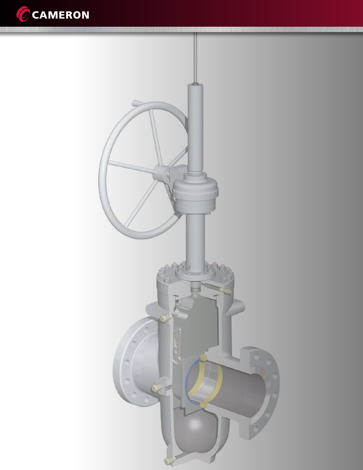
WKM Pow-R-Seal Gate Valves
High-quality, through-conduit, expanding gate valves engineered for performance in critical
isolation applications where a tight mechanical seal that is normally unaffected by pressure
variations and vibrations is needed.

1
WKM POW-R-SEAL GATE VALVES
Introduction .......................................................................................... 2
Design .................................................................................................. 3
Features ................................................................................................ 4
Options ................................................................................................. 5
Operation ............................................................................................. 6
Single Spring-Loaded (SLS) Seal ............................................................. 7
Thermal Relief System ........................................................................... 8
Models M (Handwheel Operated) ......................................................... 9
Models E1C (Handwheel and Bevel Gear Operated) .............................. 10
Model E1C (Bevel Gear Operated) ......................................................... 12
Operator Sizing Requirements ............................................................... 13
Operator Interface ................................................................................ 14
Operator Interface Dimensions Topworks Data ...................................... 15
Flow Coefficients (CV) ........................................................................... 16
Flow Coefficients (K V) ........................................................................... 17
Pressure Temperature Ratings ................................................................ 18
Trim Chart ............................................................................................ 20
Common Trims ..................................................................................... 21
Partial Open Flow Characteristics .......................................................... 22
CAMSERV Aftermarket Services for Valves and Actuation ...................... 23
Trademark Information ......................................................................... 24
Table of Contents

2
Cameron is a leading provider of valves and measurement systems to the oil and gas
industry. Our products are primarily used to control, direct, and measure the flow of
oil and gas as it is moved from individual wellheads through flowlines, gathering lines,
and transmission systems to refineries, petrochemical plants, and industrial centers
for processing.
Cameron provides a wide range of valves for use in natural gas, LNG, crude oil, and
refined products transmissions lines. The traditional CAMERON® fully welded ball valve
product line has been combined with the GROVE®, RING-O®, TOM WHEATLEY®, ENTECH™,
and TK® product lines. This broad offering has strengthened Cameron’s ability to serve as a
single source for a wide scope of customer requirements. Cameron also provides critical
service valves for refinery, chemical, and petrochemical processing businesses, and for
associated storage terminal applications, particularly through the ORBIT® and GENERAL
VALVE® lines. These brands are complemented by WKM®, TBV™, and TEXSTEAM™ valve
products and considerably expand the scope of our product offerings.
Cameron’s WKM Pow-R-Seal™ gate valve’s smooth continuous bore reduces turbulence.
Additionally, the seat faces are outside the flow stream and are protected from contact
with the lading whether the valve is in the open or closed position. The WKM Pow-R-Seal
gate valve’s full bore makes it possible to run pigs, scrapers, or hot tap cutters through the
valves without danger of damaging the valve, lodging the scraper, or jamming it with
metal cuttings.
Ville Platte, La.,
USA
WKM Pow-R-Seal Gate Valves
3
Cameron’s WKM Pow-R-Seal valve’s design provides the following specific advantages for reliable performance and long
life, even in fluid, gas, steam, and hot water critical services up to 1000° F (538° C).
Protection of Seat Faces
Seat faces are outside the flow
stream and in full contact with the
gate, in both fully open and fully
closed positions, greatly extending
the seat life.
Smooth, Continuous
Conduit for Flow
Destructive turbulence is nearly
eliminated. In a full-bore valve, pressure
drop through the valve is no greater
than that through an equal length of
equal diameter pipe.
Tight Mechanical Seal and
Double Block-and-Bleed
Capability
The WKM Pow-R-Seal valve’s parallel
expanding gate design provides a tight
mechanical seal, upstream and
downstream simultaneously, which
is
normally unaffected by pressure
variations or vibration.
Metal-to-Metal Mechanical
Sealing
The seal is unaffected by pressure
surges, vibration, or heat under normal
operating conditions. First, the seat
insert contacts the gate. Then, the
insert is compressed and a metal-to-
metal seal is established.
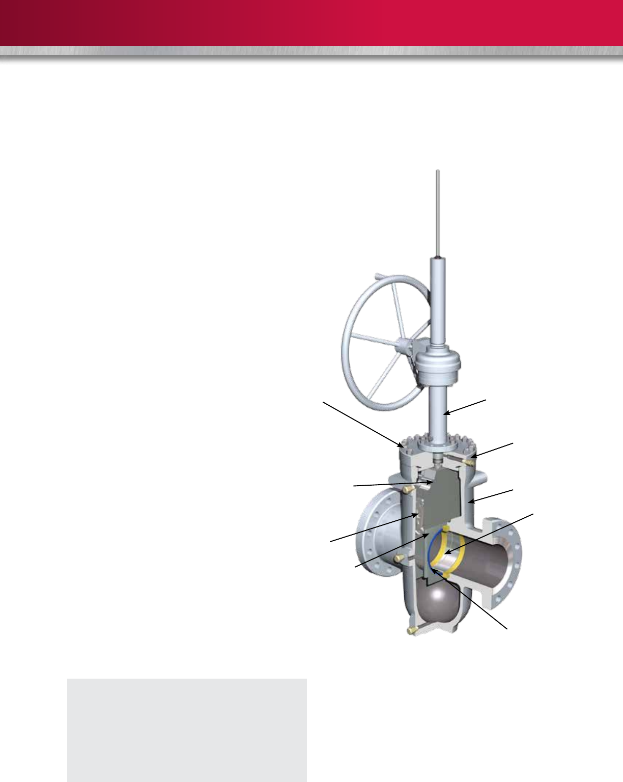
Bonnet stud and nut
Parallel expanding gate
(gate and segment)
Gate centralizer provides
positive control for
improved operation
Seat Skirt
Hardened stainless
steel stem
Body
Protected seat faces
Full-bore, through-
conduit design
reduces turbulence
and pressure drop
Bonnet
Commonly Used Applications
• Pumps station isolation
• Launchers and receivers
• Decoking systems
• Gathering lines
DESIGN

4
1. Through-Conduit Parallel Expanding Gate Valve
• Provides a tight mechanical seal
• Full-bore design reduces pressure drop and allows passage of all types of scrapers (pigs)
• Nickel-plated gate and segment standard
2. Fugitive Emissions-Tested SLS Stem Seal*
• Stem seal is completely contained in the bonnet
• Stem is centralized by bearings
• Nickel-plated stem standard
• Seal is self-adjusting and does not depend on plastic packing
• PTFE compound resists virtually all ladings
• Pedestal supports the seal and acts as a stem scraper
• 6” to 24” (150 mm to 600 mm) Class 300 to 900 valves are fire-tested to API 6FA 3rd Edition
3. Interference Fit Seats
• Double sealing and in-line replaceable
• Upstream and downstream sealing
• Block-and-bleed per API 6D standards
• Simple design is resistant to dirty service
• Insert initiates the seal and helps clean the gate**
• Seals are compatible with virtually all ladings
• Seats may be lubricated to promote long life, reduce operating torques or effect a seal in an emergency
• Fire-tested to API 6FA 3rd Edition
4. Bolted Bonnet Valve is In-Line Repairable
• Bonnet seal resists virtually all landings
• Design provides metal-to-metal, tight sealing ideal for high temperature applications
5. Yoke-Tube Upper Flanges Comply with MSS-SP102 Standards
• Simplifies operator mounting
• Can also be manufactured to comply with ISO 5240
6. Single-Piece Cast Body Center Section
• Provides the necessary strength to resist pipeline bending
• Smooth shape reduces stress concentrations
• Made from pressure vessel quality steel
7. Valve Stroke is Established by Manufacturing Tolerances
• Stays in adjustment
8. LeverLock® Gate Centralizer***
• Retains gate and segment assembly in a neutral position during opening and closing travel
• Permits expansion of the assembly at the proper moment for seating
* For Model E-1C; does not apply to high-temperature valves. In-house FE testing only.
** High-temperature valves do not have insert
*** Standard on 6” and larger valves
FEATURES
5
Bonnet Seal
• 6” to 12” (150 mm to 300 mm): flat metal gasket
• 14” to 24” (350 mm to 600 mm): O-ring seal
• High-temperature valves: spiral-wound metal gasket with a non-asbestos filler
Options
• Lubrication, packing, drain extensions
• Stem and yoke tube extensions
• Variety of coatings (coal tar epoxy for buried service, two- to three-part coating
systems for marine environment, inorganic zinc rich epoxy, etc.)
• HF-6 overlay is available on request for the gate segment assembly and seat sealing surfaces
• Handwheel operator* (position indicator standard)
• Bevel gear operator (position indicator standard)
• Less gearing (bare stem)
• Electric motor operator
• Several types of body cavity thermal relief systems available
• Variety of paint and coatings
* 6” through 10” (150 mm through 250 mm) Class 300 to 900 valves and 12” ( 300 mm) Class 300 to 600 valves only are available in selected sizes.
OPTIONS
6
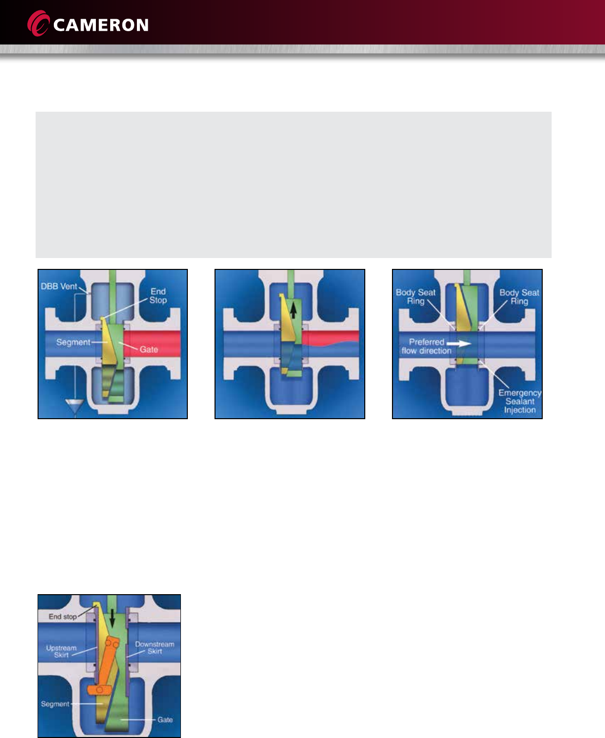
Sealed Closed
In the fully closed position, the
segment has engaged with an end
stop and the gate is wedged
downward, expanding the segment
and gate so that they form a tight
mechanical closure against the
upstream and downstream seats.
Venting the body cavity will provide
total, tight shutoff.
LeverLock Mechanism
The lever arm is held parallel to the gate faces by the skirt
plates while the assembly is moving through its stroke.
Near end-of-travel, the skirt allows the lever to tilt. The
gate and segment slide against their angled faces,
creating the expanding seal action. In their final position,
the gate and segment are mechanically secured in place.
The skirt plates are guide rails at the sides of the gate.
The skirts align the gate and segments with the seats.
60 years of worldwide service in oil, gas, chemicals,
water, slurry, and multiproduct applications has
established the WKM Pow-R-Seal valve as one of the
most trusted gate valves, where safety and seal
reliability are critical.
The parallel expanding gate design provides a tight
mechanical seal which is normally unaffected by
vibrations or pressure variations.
The rigid, cast steel body resists pipeline bending
moments which could affect seat sealing in other
valves.
PTFE seals on both faces of the valve provide drop
tight sealing, while metal-to-metal contact between
the seals and gate mechanism provides tight
shutoff.
All-metal seals also are available for service to
1000° F (538° C), where leakage rates comply
with API 6D and ISO 5208 standards.
Mid-Travel
During travel towards opening, the
gate slides across the wedge angle
of the segment, collapsing the
assembly so that it travels freely
between the seal faces. The
patented LeverLock gate centralizer
holds the mechanism in the neutral
position until seal expansion
is required.
Fully Open
When the bore in the segment is
aligned with the conduit bore, an
end stop prevents further travel
and the gate slides across the
wedge angle, expanding the gate
and the segment, isolating the flow
from the body. The preferred flow
direction ensures easier operation.
OPERATION
7
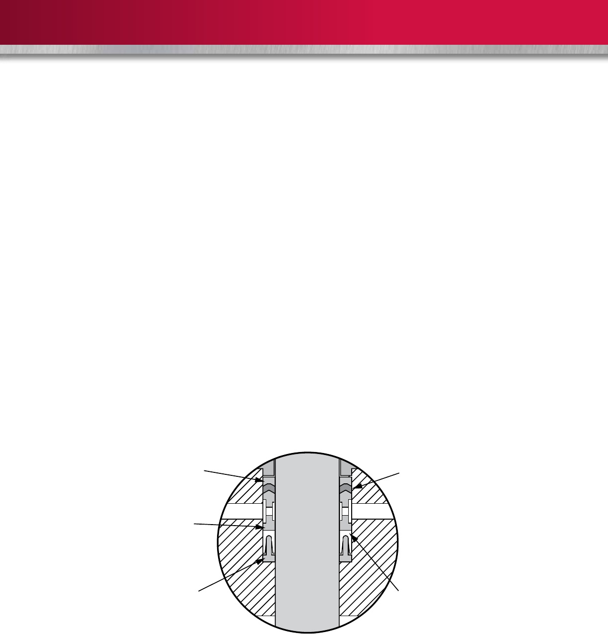
The SLS stem seal system is designed to provide
optimum performance while requiring minimal
maintenance. Our in-house lab tests have shown
FE leak rates below 500 ppm.
Testing and Certifications
• Fire tests per API 6FA, BS 6755 Part 11
• ISO 10497
Design
• Single spring-loaded lip seal
• Lantern ring
• Chevron ring(s)
• Lower pedestal
• Upper adapter
Features
• Self-adjusting seal designed to reduce maintenance
• No plastic packing required to establish an effective seal
• Four separate sealing bands to promote reliability
• Filled PTFE shell backed with a corrosion-resistant alloy
spring (making it suitable for virtually all line media)
• Metal spring provides an initial seal and uniform loading
over a wide temperature range
• Lantern ring acts as a spacer in conjunction with the upper
adapter as a bearing to center the stem
• Lower pedestal support seal acts as a stem wiper to keep
contaminants away from sealing members
• Chevron ring(s) act as an emergency seal, should it be
necessary to inject plastic packing, and keeps foreign
matter away from the seal
Pedestal supports the SLS
stem seal and acts as a wiper
to keep contaminants away
from the seals
SLS seal is hydrocarbon
fugitive emissions-tested,
compatible with most
media and ladings, and is
fire-tested to API 6FA
Chevron vee ring(s) act as a
wiper and provide a seal,
should it be necessary to
inject plastic packing
Metal upper adapter
centers the stem
Metal lantern ring centers
the stem and acts as a spacer
FEATURES AND BENEFITS
Single Spring-Loaded (SLS) Seal
8
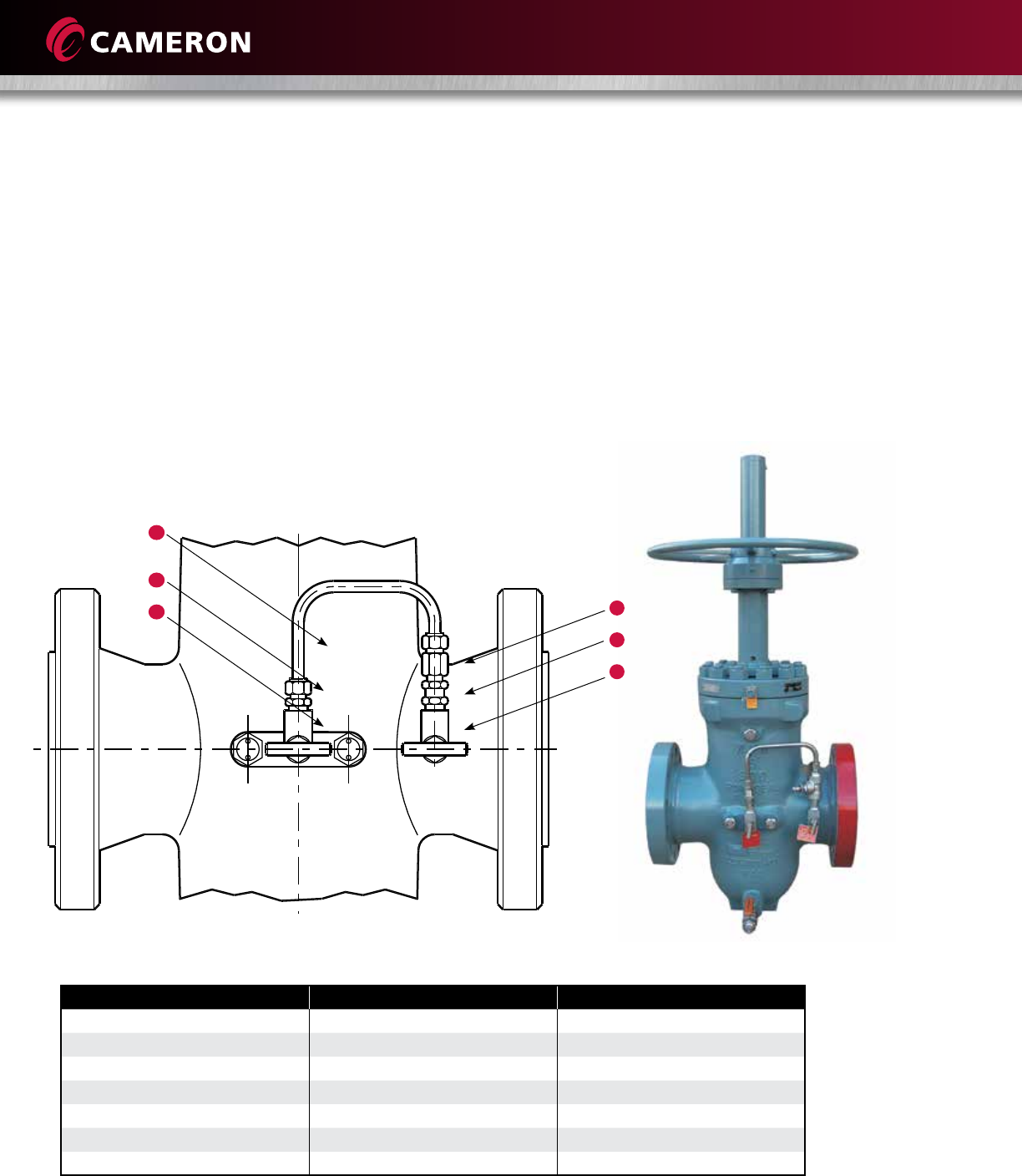
Because of the split gate design, it is possible for excess
body pressure to develop in the body cavities of closed
valves. This usually results from heating that takes place in
the valves while in liquid service. A thermal body cavity
relief system is provided to relieve this excess body
pressure. Thermal relief systems which direct excess body
pressure to the upstream conduit are standard. This
system consists of two needle valves, a check valve,
tubing and two fittings. Body pressure greater than
the segment conduit pressure causes the check valve
to unseat and relieve excess pressure to the upstream
conduit. The needle valves must be kept open while the
valve is in service. These needle valves can be used to
isolate the line pressure to service the relief systems,
as needed.
Typical Thermal Body Cavity Relief Arrangement
Item Part Qty.
1 Needle Valve 2
2 Female Tubing Connector 1
3 Check Valve 1
4 Male Tubing Connector 1
5 Tubing 1
Tag (Not Shown) 2
Wire (Not Shown) 1
Notes: These items are on the lettered side of the valve (letters not shown in diagram above).
Special thermal relief systems are available upon request.
2
3
1
5
4
1
Thermal Relief System
OPERATION
9
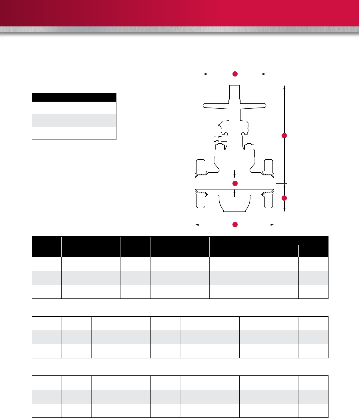
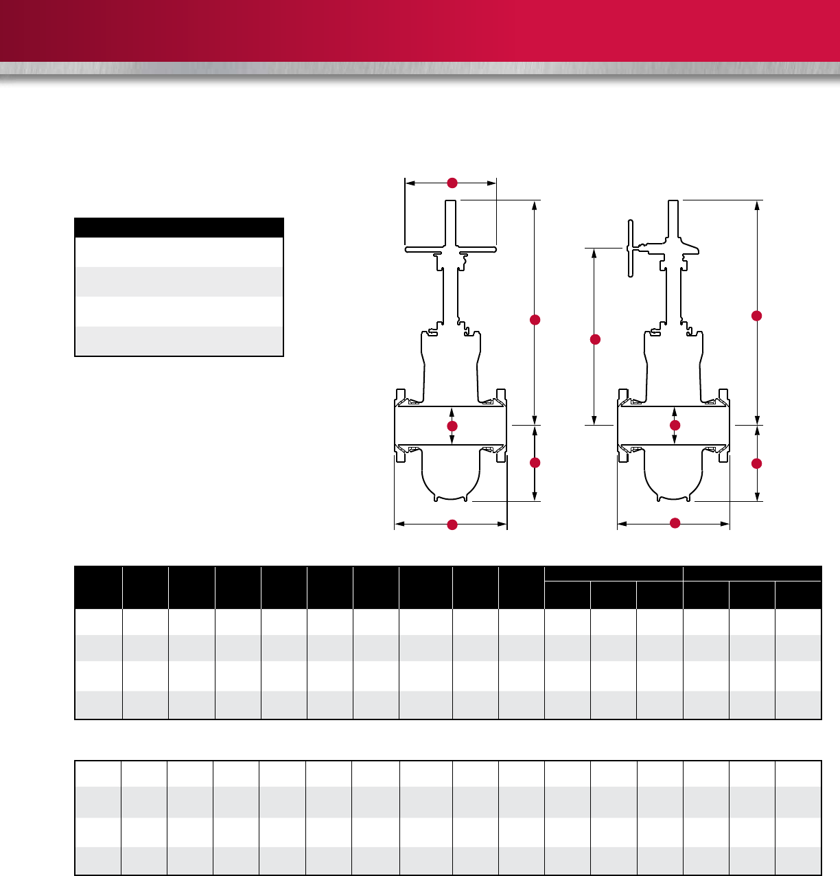
H
G
B
F
A
Max. WP at 100˚ F (38˚ C)
Class 600: 1500 psi CWP
2250 psi Test
Class 900: 2250 psi CWP
3375 psi Test
Class 1500: 3750 psi CWP
5625 psi Test
PRINCIPAL DIMENSIONS
N = Number of turns to fully open or close valve
Flange dimensions conform to American National Standards Institute Standard B16.5, 1981. Information on power-actuated and other types of valves
available on application.
Class 900
Class 1500
2 14-1/2 2-1/16 5-1/16 17-3/4 12 16 150 72 105
(50) (368) (52) (129) (451) (305) - (68) (33) (48)
3 15 3-3/16 7-5/16 23-7/8 12 20 265 193 247
(80) (381) (81) (186) (606) (305) - (120) (88) (112)
4 18 4-1/8 9-1/16 28-1/2 18 20 515 390 417
(100) (457) (105) (230) (724) (457) - (234) (177) (189)
2 14-1/2 2-1/16 5-1/16 17-3/4 12 16 150 72 105
(50) (368) (52) (129) (451) (305) - (68) (33) (48)
3 18-1/2 3-3/16 7-5/16 23-7/8 12 20 295 215 242
(80) (470) (81) (186) (606) (305) - (134) (98) (110)
4 21-1/2 4-1/8 9-1/16 28-1/2 18 20 530 403 325
(100) (546) (105) (230) (724) (457) - (240) (183) (147)
Class 600
Size in.
(mm) A B F G H N
Weight lb (kg)
FE WE F x W
2 11-1/2 2-1/16 4-13/16 17-3/4 12 16 90 72 84
(50) (292) (52) (122) (451) (305) - (41) (33) (38)
3 14 3-3/16 6-15/16 23-7/8 12 20 180 144 155
(80) (356) (81) (176) (606) (305) - (82) 1(65) (70)
4 17 4-1/8 8-5/8 27 14 20 345 259 245
(100) (432) (105) (219) (686) (356) - (156) (117) (111)
MODELS M (HANDWHEEL OPERATED)
2” to 4” (50 mm to 100 mm) Classes 600, 900, and 1500
10
Max. WP at 100˚ F (38˚ C)
Class 300: 750 psi CWP
1125 psi Test
Class 600: 1500 psi CWP
2250 psi Test
Class 900: 2250 psi CWP
3375 psi Test
Class 1500: 3750 psi CWP
5625 psi Test
* 12” (300 mm) Class 300 valves have Class 400 end-to-end dimensions.
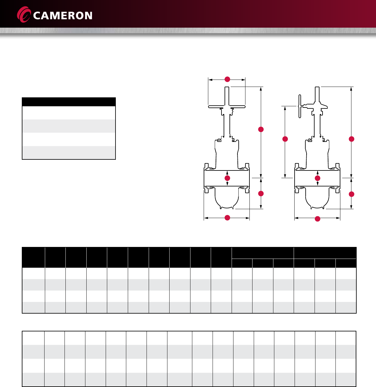
PRINCIPAL DIMENSIONS
N = Number of turns of handwheel or bevel gear
operator handwheel to fully open or close valve.
GK
Handwheel Operated Bevel Gear Operated
H
G
B
A
F
B
A
F
Class 600
Size in.
(mm) A B F G
HWO
G
BGO HKN
HWO
N
BGO
Weight lb (kg) HWO Weight lb (kg) BGO
FE WE F x W FE WE F x W
6
(150)
15-7/8
(403)
6
(152)
12-1/2
(318)
45-1/4
(1149)
46-1/4
(1175)
24
(610)
30-11/16
(779)
29
-
114
-
472
(214)
397
(180)
400
(181)
500
(227)
445
(202)
470
(213)
8
(200)
16-1/2
(419)
8
(203)
16
(406)
57-1/4
(1454)
56-1/4
(1429)
24
(610)
36-11/16
(932)
37
-
146
-
853
(387)
751
(341)
805
(365)
903
(410)
845
(383)
895
(406)
10
(250)
18
(457)
10
(254)
20
(508)
63-1/4
(1607)
64-1/4
(1632)
24
(610)
44-11/16
(1135)
45
-
180
-
1345
(610)
1200
(544)
1273
(577)
1475
(669)
1380
(626)
1448
(657)
12*
(300)
30
(762)
12
(305)
22-3/4
(578)
73-3/8
(1864)
74-5/8
(1895)
30
(762)
51-11/16
(1313)
40
-
239
----1950
(885)
1670
(757)
1880
(853)
6
(150)
22
(559)
6
(152)
12-5/8
(321)
45-1/4
(1149)
46-1/4
(1175)
24
(610)
30-11/16
(779)
29
-
114
-
595
(270)
495
(225)
545
(247)
695
(315)
575
(261)
635
(288)
8
(200)
26
(660)
8
(203)
15-1/2
(394)
57-1/4
(1454)
56-1/4
(1429)
24
(610)
36-11/16
(932)
37
-
146
-
1028
(466)
730
(331)
865
(392)
1075
(488)
895
(406)
990
(449)
10
(250)
31
(787)
10
(254)
19-3/4
(502)
64-7/8
(1648)
66-1/8
(1680)
24
(610)
45-3/16
(1148)
34
-
203
-
1735
(787)
1370
(621)
1505
(683)
1895
(860)
1585
(719)
1835
(832)
12
(300)
33
(838)
12
(305)
23
(584)
73-3/8
(1864)
74-5/8
(1895)
30
(762)
51-11/16
(1313)
40
-
239
-
2525
(1145)
2360
(1070)
2480
(1125)
3030
(1374)
2250
(1021)
2360
(1070)
Class 300
6” to 12” (150 mm to 300 mm) Classes 300 and 600
MODELS E1C
(HANDWHEEL AND BEVEL GEAR OPERATED)
11
* 12” (300 mm) Class 300 valves have Class 400 end-to-end dimensions.
Class 1500 (RTJ)
Size in.
(mm) A B F G
HWO
G
BGO HKN
HWO
N
BGO
Weight lb (kg) HWO Weight lb (kg) BGO
FE WE F x W FE WE F x W
6
(150)
24
(610)
6
(152)
12-7/8
(327)
45-1/4
(1149)
46-1/4
(1175)
24
(610)
30-3/4
(781)
29
-
114
-
743
(337)
577
(262)
625
(283)
805
(365)
565
(256)
680
(308)
8
(200)
29
(737)
8
(203)
15-3/4
(400)
57-1/4
(1454)
56-1/4
(1429)
24
(610)
36-3/4
(933)
37
-
146
-
1272
(577)
1040
(472)
1180
(535)
1329
(603)
1180
(535)
1238
(562)
10
(250)
33
(838)
10
(254)
20-1/8
(511)
64-7/8
(1648)
66-1/8
(1680)
30
(762)
45-1/4
(1149)
34
-
203
-
2250
(1021)
1930
(875)
2085
(946)
2315
(1050)
1875
(850)
2185
(991)
12
(300)
38
(965)
12
(305)
23-1/2
(597) -73-3/4
(1873)
30
(762)
56-5/8
(1438)
40
-
318
-
3392
(1539)
2725
(1236)
2860
(1297)
3600
(1633)
2880
(1306)
3276
(1486)
6
(150)
28
(711)
5-3/4
(146)
14-5/8
(371) -61
(1549) -49
(1245)
22
-----1735
(788)
1486
(676)
1611
(732)
8
(200)
33-1/8
(841)
7-5/8
(194)
18-1/4
(464) -66-1/2
(1689) -54-1/2
(1384)
29
-----3181
(1446)
2979
(1354)
3080
(1400)
10
(250)
39-3/8
(1000)
9-1/2
(241)
22-1/4
(565) -79
(2007) -67
(1702)
36
-----4094
(1861)
3492
(1587)
3793
(1724)
12
(300)
45-1/8
(1146)
11-3/8
(289)
26-3/8
(670) -90
(2286) -72
(1829) -----7603
(3456)
6443
(2929)
7028
(3195)
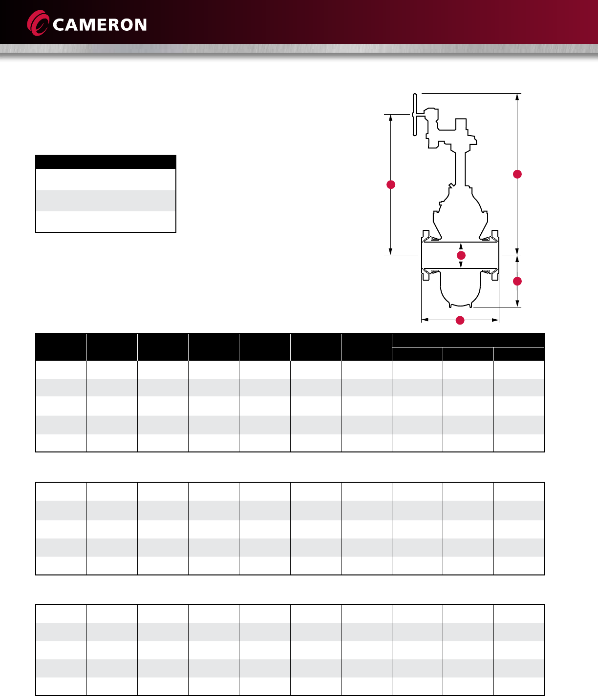
PRINCIPAL DIMENSIONS
N = Number of turns of handwheel or bevel gear
operator handwheel to fully open or close valve.
Max. WP at 100˚ F (38˚ C)
Class 300: 750 psi CWP
1125 psi Test
Class 600: 1500 psi CWP
2250 psi Test
Class 900: 2250 psi CWP
3375 psi Test
Class 1500: 3750 psi CWP
5625 psi Test
Class 900
H
G
F
B
A
G
F
K
B
A
Handwheel-Operated Bevel-Gear Operated
MODELS E1C
(HANDWHEEL AND BEVEL GEAR OPERATED)
6” to 12” (150 mm to 300 mm) Classes 900 and 1500 (RTJ)
12
Size in.
(mm) A B F G K N Weight lb (kg)
FE WE F x W
14*
(350)
32-1/2
(826)
13-1/4
(337)
25-1/4
(641)
65-7/8
(1673)
53
(1346)
177
-
2632
(1194)
2230
(1012)
2500
(1134)
16
(400)
33
(838)
15-1/4
(387)
28-1/8
(714)
83-9/16
(2122)
58-3/8
(1483)
167
-
3450
(1565)
3015
(1368)
3310
(1501)
18
(450)
36
(914)
17-1/4
(438)
31
(787)
86-13/16
(2205)
65-5/16
(1659)
190
-
4650
(2109)
4260
(1932)
4375
(1984)
20
(500)
39
(991)
19-1/4
(489)
35-1/4
(895)
106-1/4
(2699)
73-7/8
(1876)
211
-
6248
(2834)
5780
(2622)
6000
(2722)
24*
(600)
48-1/2
(1232)
23-1/4
(591)
42
(1067)
115-3/4
(2940)
86-3/8
(2194)
253
-
10,678
(4843)
9550
(4332)
10,240
(4645)
PRINCIPAL DIMENSIONS
N = Number of turns of handwheel or bevel gear
operator handwheel to fully open or close valve.
G
B
A
K
F
14
(350)
35
(889)
13-1/4
(337)
25-9/16
(649)
69-3/4
(1772)
53-1/2
(1359)
177
-
3240
(1470)
2931
(1329)
3000
(1361)
16
(400)
39
(991)
15-1/4
(387)
28-1/8
(714)
81-1/8
(2061)
61-1/4
(1556)
167
-
4420
(2005)
3950
(1792)
4160
(1887)
18
(450)
43
(1092)
17-1/4
(438)
31-5/8
(803)
86-1/2
(2197)
66-5/8
(1692)
190
-
5705
(2588)
5115
(2320)
5200
(2359)
20
(500)
47
(1194)
19-1/4
(489)
36
(914)
98-1/8
(2492)
73-7/8
(1876)
211
-
7595
(3445)
7115
(3227)
6605
(2996)
24
(600)
55
(1397)
23-1/4
(591)
42-1/4
(1073)
113-1/2
(2883)
87-7/8
(2232)
253
-
12,994
(5894)
11,380
(5162)
12,730
(5774)
Max. WP at 100˚ F (38˚ C)
Class 300: 750 psi CWP
1125 psi Test
Class 600: 1500 psi CWP
2250 psi Test
Class 900: 2250 psi CWP
3375 psi Test
14
(350)
40-1/2
(1029)
12-3/4
(324)
26-1/8
(664)
69-3/4
(1772)
53-1/2
(1359) -5200
(2359)
4902
(2224)
4902
(2224)
16
(400)
44-1/2
(130)
14-3/4
(375)
30-1/4
(768)
81-1/8
(2061)
66-5/8
(1692)
174
-
7346
(3332)
6435
(2919)
6959
(3155)
18
(450)
48
(1219)
16-3/4
(425)
33
(838)
92
(2337) - - 11,814
(5359)
10,226
(4638)
11,020
(4999)
20
(500)
52
(1321)
18-5/8
(473)
36
(914)
103
(2616) - - 15,581
(7067)
14,265
(6470)
14,866
(6743)
24
(600)
61
(1549)
22-1/2
(572)
44-1/2
(1130)
113-1/2
(2883)
87-7/8
(2232) -20,467
(9284)
18,561
(8419)
19,887
(9021)
*14” to 24” (350 mm to 600 mm) Class 300 valves have Class 400 end-to-end dimensions.
Note: 30” and 36” (750 mm and 900 mm). Class 300 and 600 prices are available upon request.
Class 300
Class 600
Class 900
14” to 24” (350 mm to 600 mm) Classes 300, 600, and 900
MODELS E1C
(BEVEL GEAR OPERATED)
13
Valve
Size
in.
(mm)
ASME
Class
ASME
Working
Pressure
(psig)
Stem Thread Recommended
Operating
Thrust
(lbf)
Recommended
Operating
Torque
(ft-lbf)
Block-
and-
Bleed
Thrust
(lbf)
Block-
and-
Bleed
Torque
(ft-lbf)
Maximum
Allowable
Thrust
(lbf)
Maximum
Allowable
Torque
(ft-lbf)
Total
Stem
Travel
in. (mm)
Stem Nut
Turns-to-
Open
Valve
Size
in.
Pitch
in.
Lead
in.
2 (50) 150 290 0.875 0.167 0.167 457 3 535 4 12,597 93 2.63 (67) 16
2 (50) 300 750 0.875 0.167 0.167 1183 9 1383 10 12,597 93 2.63 (67) 16
2 (50) 600 1500 0.875 0.167 0.167 2366 17 2766 20 12,597 93 2.63 (67) 16
2 (50) 900 2250 0.875 0.167 0.167 3549 26 4149 30 12,597 93 2.63 (67) 16
2 (50) 1500 3750 0.875 0.167 0.167 5914 43 6915 51 12,597 93 2.63 (67) 16
3 (80) 150 290 1.000 0.200 0.200 803 7 1115 9 16,027 136 4.03 (102) 21
3 (80) 300 750 1.000 0.200 0.200 2078 18 2884 25 16,027 136 4.03 (102) 21
3 (80) 600 1500 1.000 0.200 0.200 4155 35 5769 49 16,027 136 4.03 (102) 21
3 (80) 900 2250 1.000 0.200 0.200 6233 53 8653 74 16,027 136 4.03 (102) 21
3 (80) 1500 3750 1.000 0.200 0.200 10,388 88 14,422 123 16,027 136 4.03 (102) 21
4 (100) 150 290 1.250 0.250 0.250 1327 14 1783 19 25,442 271 4.88 (124) 20
4 (100) 300 750 1.250 0.250 0.250 3432 37 4610 49 25,442 271 4.88 (124) 20
4 (100) 600 1500 1.250 0.250 0.250 6864 73 9221 98 25,442 271 4.88 (124) 20
4 (100) 900 2250 1.250 0.250 0.250 10,297 110 13,831 147 25,442 271 4.88 (124) 20
4 (100) 1500 3750 1.250 0.250 0.250 17,161 183 23,052 245 25,442 271 4.88 (124) 20
Valve
Size
in.
(mm)
ASME
Class
ASME
Working
Pressure
(psig)
Stem Thread Recommended
Operating
Thrust
(lbf)
Recommended
Operating
Torque
(ft-lbf)
Block-
and-
Bleed
Thrust
(lbf)
Block-
and-
Bleed
Torque
(ft-lbf)
Maximum
Allowable
Thrust
(lbf)
Maximum
Allowable
Torque
(ft-lbf)
Total
Stem
Travel
in. (mm)
Stem Nut
Turns-to-
Open
Valve
Size
in.
Pitch
in.
Lead
in.
6 (150) 300 750 1.50 0.250 0.250 6626 82 8179 101 21,711 267 7.19 (183) 29
6 (150) 600 1500 1.50 0.250 0.250 13,252 163 16,358 201 21,711 267 7.19 (183) 29
6 (150) 900 2250 1.50 0.250 0.250 19,878 245 24,538 302 33,158 408 7.19 (183) 29
8 (200) 300 750 1.75 0.250 0.250 10,705 149 12,626 176 23,678 329 9.12 (232) 36
8 (200) 600 1500 1.75 0.250 0.250 21,410 298 25,253 351 26,577 370 9.12 (232) 36
8 (200) 900 2250 1.75 0.250 0.250 32,115 447 37,879 527 42,377 590 9.12 (232) 36
10 (250) 300 750 2.25 0.333 0.333 16,462 296 19,385 349 36,141 651 11.31 (287) 34
10 (250) 600 1500 2.25 0.333 0.333 32,924 593 3871 698 46,433 836 11.31 (287) 34
10 (250) 900 2250 2.25 0.333 0.333 49,386 889 58,156 1047 76,635 1380 11.31 (287) 34
12 (300) 300 750 2.25 0.333 0.333 21,911 395 27,588 497 52,472 945 13.38 (340) 40
12 (300) 600 1500 2.25 0.333 0.333 43,822 789 55,175 994 64,733 1166 13.38 (340) 40
12 (300) 900 2250 2.25 0.333 0.333 65,732 1184 82,763 1490 84,560 1523 13.38 (340) 40
14 (350) 300 750 2.00 0.250 0.500 25,138 477 32,355 614 78,209 1485 14.88 (378) 30
14 (350) 600 1500 2.00 0.250 0.500 50,276 955 64,709 1229 78,209 1485 14.88 (378) 30
14 (350) 900 2250 2.25 0.333 0.333 72,608 1308 101,857 1835 110,039 1982 14.88 (378) 45
16 (400) 300 750 2.50 0.400 0.800 33,517 868 39,174 1015 108,946 2822 16.88 (429) 21
16 (400) 600 1500 2.50 0.400 0.800 67,035 1736 78,348 2029 108,946 2822 16.88 (429) 21
16 (400) 900 2250 2.75 0.400 0.800 97,481 2681 146,275 4022 162,485 4468 17.38 (441) 22
18 (450) 300 750 2.50 0.400 0.800 41,440 1073 48,846 1265 113,120 2930 18.94 (481) 24
18 (450) 600 1500 2.50 0.400 0.800 82,881 2147 97,691 2530 113,120 2930 18.94 (481) 24
18 (450) 900 2250 3.00 0.400 0.400 123,194 2901 173,424 4084 185,236 4362 19.88 (505) 50
20 (500) 300 750 2.75 0.400 0.800 51,116 1406 60,201 1655 113,120 3111 21.12 (536) 27
20 (500) 600 1500 2.75 0.400 0.800 102,231 2811 120,401 3311 129,553 3562 21.12 (536) 27
20 (500) 900 2250 3.5 0.400 0.800 153,347 4953 248,075 8031 253,737 8196 21.12 27
22 (550) 300 No Design
22 (550) 600 1500 3.00 0.400 0.800 123,768 3601 149,487 4349 118,661 3453 23.25 (591) 29
22 (550) 900 No Design
24 (600) 300 750 3.00 0.400 0.800 72,557 2111 91,789 2671 113,120 3291 25.25 (641) 32
24 (600) 600 1500 3.00 0.400 0.800 145,115 4222 183,577 5341 203,038 5908 25.25 (641) 32
24 (600) 900 2250 3.75 0.400 0.800 214,524 7273 356,572 12,089 351,789 11,927
Model M – 2” to 4” (50 mm to 100 mm) ASME Classes 150 to 1500
Model E1C – 6” to 24” (150 mm to 600 mm) ASME Classes 300 to 900
Note: 1. Use recommended operating thrust and torques for sizing bevel gear operators.
2. Use block-and-bleed thrusts and torques for sizing power operators (electric, gas, hydraulic, etc.).
3. Maximum operating thrust and torques are the maximum allowable for the valve.
OPERATOR SIZING REQUIREMENTS
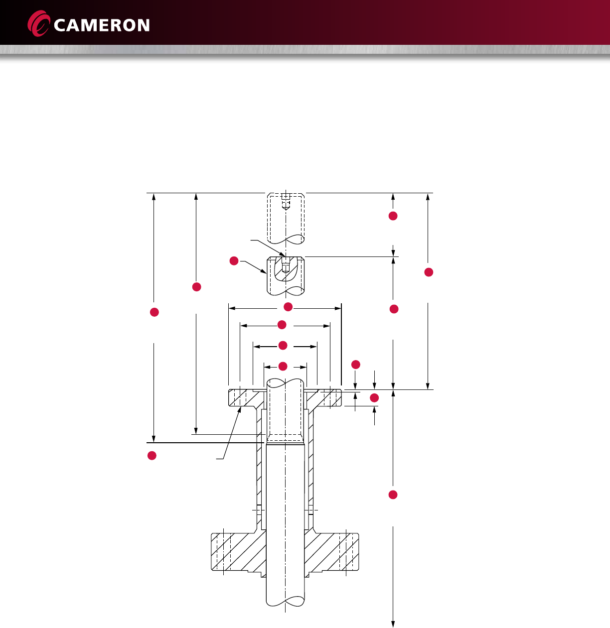
14
The operator interface on 6” through 12” (150 mm through 300 mm) valves is manufactured to comply
with ISO 5210 and MSS-SP-102.
The operator interface on 14” (350 mm) and larger valves is manufactured to comply with MSS-SP-102.
A
H
J
L
MP
N
K
G
To Centerline
of Valve Bore
= Number and
Size of Holes
E
End of Stem
THD. DIA
F
Minimum
Full THD.
1/4” - 18NPT
D
Total Stem
Travel
C
Top of
Stem Open
B
Top of
Stem Closed
ø
ø
ø
ø
OPERATOR INTERFACE

15
Size in. Class MSS A-NA-2G-L.H. B C D E F G H J K L M N P
FLG
63-9C FA14 1-1/2-.250P-.250L
Single Lead Thread
8.31 15.50 7.19 16.44 16.06 26.88 7.00 5.50 4-0.69 3.955
3.945
2.50 1.03 0.178
83-9C FA14 1-3/4-.250P-.250L
Single Lead Thread
8.44 17.56 9.12 18.94 18.56 32.00 7.00 5.50 4-0.69 3.955
3.945
2.50 1.03 0.178
10 3-9C FA16 2.25-.333P--.333L
Single Lead Thread
9.38 20.69 11.31 24.38 24.00 42.13 8.38 6.50 4-0.81 5.230
5.220
3.12
3.75
1.50
2.75
0.230
12 3-6C FA16 2.25-.333P-.333L
Single Lead Thread
11.50 24.88 13.38 26.06 25.69 45.44 8.38 6.50 4-0.81 5.230
5.220
3.12 1.50 0.230
9C FA16 2.25-.333P-.333L
Single Lead Thread
11.34 24.75 13.38 26.06 25.69 45.56 8.38 6.50 4-0.81 5.230
5.220
3.12 1.50 0.230
14 3-6C FA16 2-.250P-.500L
Double Lead Thread
9.56 24.38 14.81 27.50 26.88 50.44 8.38 6.50 4-0.81 5.230
5.220
3.12 1.50 0.230
16 3-6C FA25 2-1/2-.400P-.800L
Double Lead Thread
10.19 27.06 16.88 31.19 30.56 56.50 11.50 10.00 8-0.69 6.020
6.010
3.75 2.00 0.230
18 3-6C FA25 2-1/2-.400P-.800L
Double Lead Thread
9.31 28.25 18.94 32.69 32.19 63.88 11.50 10.00 8-0.69 6.020
6.010
3.75 2.00 0.230
20 3C FA25 2-3/4-.400P-.800L
Double Lead Thread
11.50 32.62 21.12 37.00 36.44 70.31 11.50 10.00 8.-0.69 6.020
6.010
3.75 2.00 0.230
6C FA30 2-3/4-.400P-.800L
Double Lead Thread
11.50 32.62 21.12 37.00 36.44 70.31 13.62 11.75 8-0.81 7.020
7.010 3.75 2.75 0.230
24 3C FA25 3-.400P-.800L
Double Lead Thread
12.37 37.62 25.25 43.06 42.56 85.19 11.50 10.00 8-.069 6.020
6.010
3.75 2.00 0.230
6C FA35 3-.400P-.800L
Double Lead Thread
12.37 37.62 25.25 43.06 42.56 85.19 16.12 14.00 8-1.12 8.520
8.510
4.00 3.25 0.230
Size
mm Class MSS A-NA-2G-L.H. B C D E F G H J K L M N P
FLG
150 3-9C FA14 38.1-.250P-.250L
Single Lead Thread
211 394 183 418 408 683 178 140 4-17.53 100.46
100.20
63.5 26.16 4.52
200 3-9C FA14 44.45-.250P-.250L
Single Lead Thread
214 446 232 481 471 813 178 140 4-17.53 100.46
100.20
63.5 26.16 4.52
250 3-9C FA16 57.15-.333P-.333L
Single Lead Thread
238 526 287 619 610 1070 213 165 4-20.57 132.84
132.59
79.25
95.25
38.1
69.85
5.84
300 3-6C FA16 57.15-.333P-.333L
Single Lead Thread
292 632 340 662 653 1154 213 165 4-20.57 132.84
132.59
79.25 38.1 5.84
9C FA16 57.15-.333P-.333L
Single Lead Thread
288 629 340 662 653 1157 213 165 4-20.57 132.84
132.59
79.25 38.1 5.84
350 3-6C FA16 50.8-.250P-.500L
Double Lead Thread
243 619 376 699 683 1281 213 165 4-20.57 132.84
132.59
79.25 38.1 5.84
400 3-6C FA25 63.5-.400P-.800L
Double Lead Thread
259 687 429 792 776 1435 292 254 8-17.53 152.91
152.65
95.25 50.8 5.84
450 3-6C FA25 63.5-.400P-.800L
Double Lead Thread
9.31 718 481 830 818 1623 292 254 8-17.53 152.91
152.65
95.25 50.8 5.84
500 3C FA25 69.85-.400P-.800L
Double Lead Thread
292 829 536 940 926 1786 292 254 8-17.53 152.91
152.65
95.25 50.8 5.84
6C FA30 69.85-.400P-.800L
Double Lead Thread
292 829 536 940 926 1786 346 298 8-20.57 178.31
178.10
95.25 69.85 5.84
600 3C FA25 76.2-.400P-.800L
Double Lead Thread
314 956 641 1094 1081 2164 292 254 8-17.53 152.91
152.65
95.25 50.8 5.84
6C FA35 76.2-.400P-.800L
Double Lead Thread
314 956 641 1094 1081 2164 409 356 8-28.45 216.41
216.15
101.6 82.55 5.84
Imperial
Metric
OPERATOR INTERFACE DIMENSIONS TOPWORKS DATA

16
Valve Size in.
(mm) 300 400 600 900 1500 2500
2 (50) 432 378 378 337 337 218
3 x 2 (80 x 50) - 165 165 203 239 -
2-1/2 (65) - 682 682 558 558 305
3 (80) 1155 1053 1109 1072 966 474
4 x 3 (100 x 80) - 534 529 597 677 624
4 (100) 2176 1925 1944 1890 1730 725
6 x 4 (150 x 100) - 886 944 943 1231 -
6 (150) 5300 4860 4577 4383 3622 2510
8 x 6 (200 x 150) 2499 - 3240 3588 2137 -
8 (200) 11,054 9345 8886 8416 6879 5227
10 x 8 (250 x 200) 5218 - 5036 7975 4859 -
12 x 8 (300 x 200) 3302 - 3892 ---
10 (250) 18,856 15,771 14,533 14,087 11,283 8313
12 (300) (Note 1) 228,980 23,834 22,729 21,025 16,843 12,282
12 x 10 (300 x 250) - - 12,799 7299 - -
14 (350) (Note 1) 30,883 29,921 28,837 23,846 20,336 -
16 x 14 (400 x 350) - - 21,096 - - -
16 (400) 42,224 41,022 39,144 33,358 27,548 21,396
20 x 16 (500 x 400) - 15,761 - - - -
18 (450) 55,740 54,277 51,368 45,004 - -
20 (500) 70,386 68,680 64,559 56,871 - -
22 (550) 86,869 85,422 80,279 ---
24 (600) (Note 1) 106,835 103,504 97,240 84,836 - -
26 (650) 123,222 120,829 114,905 ---
28 (700) 144,355 142,391 135,267 - - -
30 (750) 170,229 163,776 157,401 133,706 - -
36 (900) 245,362 236,147 224,424 ---
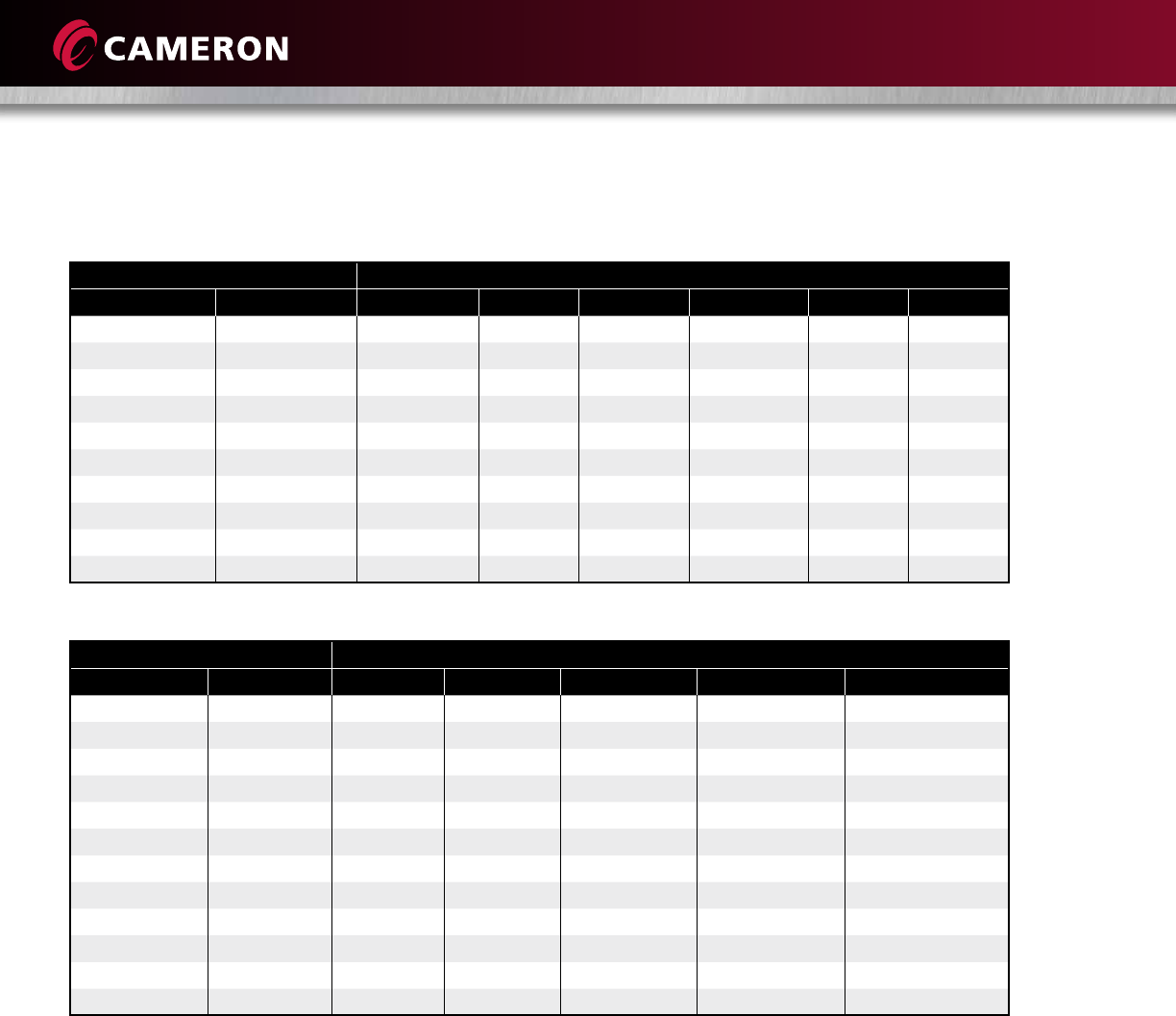
The following chart outlines the CV for through conduit gate valves having end-to-end dimensions and bore diameters in
compliance with API 6D.*
Since CV is a calculated number, the actual value may vary.
* As Applicable.
Notes: 1. Class 300 valves have Class 400 end-to-ends in these size Pow-R-Seal designs. Use the Class 400 CV.
FLOW COEFFICIENTS (CV)

17
Valve Size in.
(mm) 300 400 600 900 1500 2500
2 (50) 373 327 327 291 291 188
3 x 2 (80 x 50) - 142 145 175 207 -
2-1/2 (65) - 590 590 483 483 264
3 (80) 999 911 959 927 835 410
4 x 3 (100 x 80) - 462 458 516 585 540
4 (100) 1882 1665 1682 1635 1496 627
6 x 4 (150 x 100) - 766 817 816 1065 -
6 (150) 4585 4204 3959 3792 3133 2172
8 x 6 (200 x 150) 2162 - 2803 3103 1849 -
8 (200) 9562 8084 7687 7280 5951 4522
10 x 8 (250 x 200) 4514 - 4356 6898 4204 -
12 x 8 (300 x 200) 2857 - 3367 - - -
10 (250) 16,312 13,643 12,572 12,186 9761 7191
12 (300) (Note 1) 25,070 20,617 19,662 18,188 14,570 10,624
12 x 10 (300 x 250) - - 11,072 6314 - -
14 (350) (Note 1) 26,715 25,883 24,945 20,628 17,591 -
16 x 14 (400 x 350) ------
16 (400) - - 18,249 - - -
20 x 16 (500 x 400) 36,526 35,486 33,862 28,856 23,831 18,509
18 (450) - 13,634 - - - -
20 (500) 48,218 46,953 44,436 38,930 - -
22 (550) 60,888 59,412 55,847 49,196 - -
24 (600) (Note 1) 75,147 73,894 69,445 - - -
26 (650) 92,417 89,536 84,117 73,388 - -
28 (700) 106,593 104,523 99,399 - - -
30 (750) 124,874 123,175 117,013 ---
36 (900) 147,257 141,674 136,160 115,662 - -
40 x 30
(1000 x 750) - - - 60,464 - -
36 (900) 212,251 204,279 194,138 - - -
42 x 36
(1050 x 900) 70,357 - - - - -
40 (1000) 266,697 265,814 265,814 - - -
42 (1050) - 302,576 293,854 ---
48 (1200) - - 408,871 - - -
The following chart outlines the KV for through conduit gate valves having end-to-end dimensions and bore diameters in
compliance with API 6D.*
Since KV is a calculated number, the actual value may vary.
* As Applicable.
Notes: 1. Class 300 valves have Class 400 end-to-ends in these size Pow-R-Seal designs. Use the Class 400 KV.
FLOW COEFFICIENTS (KV)
18
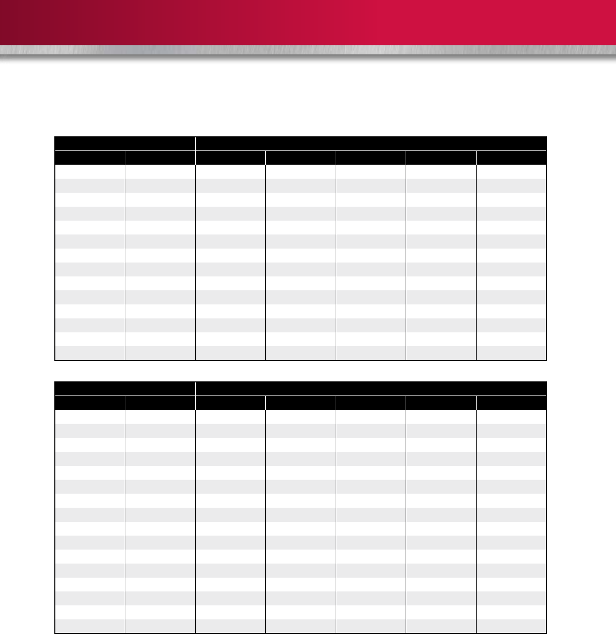
Temperature Working Pressure by Class, psig
°C °F 150 300 400 600 900 1500
29° C to 38° C 20° F to 100° F 290 750 1000 1500 2250 3750
93° C 200° F 260 750 1000 1500 2250 3750
149° C 300° F 230 730 970 1455 2185 3640
204° C 400° F 200 705 940 1410 2115 3530
260° C 500° F 170 665 885 1330 1995 3325
316° C 600° F 140 605 805 1210 1815 3025
343° C 650° F 125 590 785 1175 1765 2940
371° C 700° F 110 570 755 1135 1705 2840
399° C 750° F 95 505 670 1010 1510 2520
427° C 800° F 80 410 550 825 1235 2060
Temperature Working Pressure by Class, psig
°C °F 150 300 600 900 1500
-29° C to 38° C -20° F to 100° F 19.8 51.7 103.4 155.1 258.6
50° C 122° F 19.5 51.7 103.4 155.1 258.6
100° C 212° F 17.7 51.5 103.0 154.6 257.6
150° C 302° F 15.8 50.2 100.3 150.5 250.8
200° C 392° F 13.8 48.6 97.2 145.8 243.2
250° C 482° F 12.1 46.3 97.2 139.0 231.8
300° C 572° F 10.2 42.9 85.7 128.6 214.4
325° C 617° F 9.3 41.4 82.6 124.0 206.6
350° C 662° F 8.4 40.0 80.0 120.1 200.1
375° C 707° F 7.4 37.8 75.7 113.5 189.2
400° C 752° F 6.5 34.7 69.4 104.2 173.6
425° C 797° F 5.5 28.8 57.5 86.3 143.8
Ref.: API 6D, ASME B16.34
General Notes: (a) Flanged end valve ratings terminate at 1000° F (538° C).
Standard WCC Material
PRESSURE TEMPERATURE RATINGS
19
Temperature Working Pressure by Class, psig
°C °F 150 300 600 900 1500
-29° C to 38° C -20° F to 100° F 290 750 1500 2250 3750
93° C 200° F 260 750 1500 2250 3750
149° C 300° F 230 720 1445 2165 3610
204° C 400° F 200 695 1385 2080 3465
260° C 500° F 170 665 1330 1995 3325
316° C 600° F 140 605 1210 1815 3025
343° C 650° F 125 590 1175 1765 2940
371° C 700° F 110 570 1135 1705 2840
399° C 750° F 95 530 1065 1595 2660
427° C 800° F 80 510 1015 1460 2540
454° C 850° F 65 485 975 1350 2435
482° C 900° F 50 450 900 955 2245
510° C 950° F 35 320 640 650 1595
538° C 1000° F 20 215 430 430 1080
Temperature Working Pressure by Class, psig
°C °F 150 300 600 900 1500
-28° C to 38° C -20° F to 100° F 19.8 51.7 103.4 155.1 258.6
50° C 122° F 19.5 51.7 103.4 155.1 258.6
100° C 212° F 17.7 51.5 103.0 154.4 257.4
150° C 302° F 15.8 49.7 99.5 149.2 248.7
200° C 392° F 13.8 48.0 95.9 143.9 239.8
250° C 482° F 12.1 46.3 92.7 139.0 231.8
300° C 572° F 10.2 42.9 85.7 128.6 214.4
325° C 617° F 9.3 41.4 82.6 124.0 206.6
350° C 662° F 8.4 40.3 80.4 120.7 201.1
375° C 707° F 7.4 38.9 77.6 116.5 194.1
400° C 752° F 6.5 36.5 73.3 109.8 183.1
425° C 797° F 5.5 35.2 70.0 105.1 175.1
450° C 842° F 4.6 33.7 67.7 101.4 169.0
475° C 887° F 3.7 31.7 63.4 95.1 158.2
500° C 932° F 2.8 25.7 51.5 77.2 128.6
538° C 1000° F 1.4 14.9 29.8 44.7 74.5
General Notes: (a) Flanged end valve ratings terminate at 1000° F (538° C).
Standard WC6 Material
PRESSURE TEMPERATURE RATINGS

20
Service Trim
Code
Body and
Bonnet
Gate and
Segment Seat Stem
Seal Stem Bolting Fittings Temperature
Range
Waterflood,
Corrosive T-10
WCC Carbon
Steel, Nickel-
Plated
Carbon Steel 300-
600, Low Alloy 900
Nickel-Plated
Carbon Steel,
Nickel-Plated
PTFE Insert
PTFE
Low Alloy
Steel, Nickel-
Plated
Alloy Steel
NACE Stainless Steel -20° F to 250° F
(-29° C to 121° C)
Standard
2”- 4” only T-11 WCC
Carbon Steel
Carbon Steel, Low
Alloy Steel, Nickel-
Plated
Carbon Steel,
Nickel-Plated
PTFE Insert
FKM
Viton
Low Alloy
Steel, Nickel-
Plated
Alloy Steel Carbon Steel -20° F to 250° F
(-29° C to 121° C)
Sour, Mildly
Corrosive
2” and larger
T-24 WCC
Carbon Steel
Carbon Steel 300-
600, Low Alloy 900
Nickel-Plated
Carbon Steel,
Nickel-Plated
PTFE Insert
PTFE
Low Alloy
Steel, Nickel-
Plated
Alloy Steel
NACE Stainless Steel -20° F to 250° F
(-29° C to 121° C)
High-Temperature T-30 WCC
Carbon Steel
CA6NM Stainless
Steel, HF-6 Hard
Faced
Carbon Steel,
HF-6 Hard
Faced
Flexible
Graphite
400 Series
Stainless Steel Alloy Steel Stainless Steel -20° F to 650° F
(-29° C to 343° C)
High-Temperature T-31 WC6
Carbon Steel
CA6NM Stainless
Steel, HF-6 Hard
Faced
A182 F11
Carbon Steel,
HF-6 Hard
Faced
Flexible
Graphite
400 Series
Stainless Steel Alloy Steel Stainless Steel -20° F to 1000° F
(-29° C to 538° C)
Low-Temperature,
Non-Sour T-36
LCC Carbon
Steel Impact-
Tested
Nickel-Plated Carbon
Steel 300-600 Low
Alloy Steel 900 Class
Carbon Steel,
Nickel-Plated
PTFE Insert
PTFE
Low Alloy
Steel, Impact
Nickel-Plated
Alloy Steel,
Impact-
Tested
Stainless Steel -50° F to 250° F
(-46° C to 121° C)
Low-Temperature,
Sour T-37
LCC Carbon
Steel Impact-
Tested
Nickel-Plated Carbon
Steel 300-600 Low
Alloy Steel 900 Class
Carbon Steel,
Nickel-Plated
PTFE Insert
PTFE
Low Alloy
Steel, Impact
Nickel-Plated
Alloy Steel,
Impact-
Tested
Stainless Steel -50° F to 250° F
(-46° C to 121° C)
Standard
6” and larger T-101 WCC Carbon
Steel
Carbon Steel 300-
600, Low Alloy 900
Nickel-Plated
Carbon Steel,
Nickel-Plated
PTFE Insert
PTFE
Low Alloy
Steel, Impact
Nickel-Plated
Alloy Steel Carbon Steel -20° F to 250° F
(-29° C to 121° C)
Standard Special
Services
6” and larger
T-102 WCC Carbon
Steel
Carbon Steel 300-
600, Low Alloy 900
Nickel-Plated
Carbon Steel,
Nickel-Plated
PTFE Insert
PTFE
Low Alloy
Steel, Impact
Nickel-Plated
Alloy Steel Carbon Steel -20° F to 250° F
(-29° C to 121° C)
TRIM CHART

21
Waterflood (Uninhibited) (T-10) – Carbon steel body/bonnet with wetted surface, ENP-plated, internal parts of
corrosion-resistant materials.
Model M (Sizes 2” to 4”, (50 mm to 100 mm), Classes 600 through 1500) Standard (T-11) – For non-corrosive aromatic
service with concentration of MTBE to 100%.
Sour Gas and Oil (NACE MR0175) (T-24) – Primarily for sour gas and oil (NACE MR0175) where resistance to H2S
embrittlement is required. Also suitable for other chemicals, products or hydrocarbons when H2S is present. May be used
when CO2 is present in smaller amounts than H2S.
High-Temperature -20° F to 650° F (-29° C to 343° C) (T-30) – For higher temperature service where the corrosion
resistance and wire drawing resistance of the stainless internals with stellite overlay are suitable. The limiting temperature is a
function of the body material which follows the appropriate pressure rating table. (Ref. ASME Std. B16.34, 1977).
High-Temperature Up to 1000° F (538° C) (T-31) – For service above 550° F (288° C). Same qualifications as T-30, except
metal-to-metal seating is only required for temperatures from 650° F to 1000° F (343° C to 538° C).
Low-Temperature -50° F (-46° C) NACE (T-36) – For essentially non-corrosive ladings, either liquid or gaseous. The pressure-
retaining components (body, bonnet and bolting) are of impact-tested materials.
Low-Temperature Sour -50° F (-46° C) NACE (T-37) – Primarily for sour gas and oil (NACE MR0175) where resistance to H2S
embrittlement is required at -50° F (-46° C) service. The pressure-retaining components (body, bonnet and bolting) are of
impact-tested materials. Also suitable for other chemicals, products or hydrocarbons when H2S is present. Can be used when
CO2 is present in smaller amounts than H2S.
Aromatic (to 40% MTBE, Fire-Tested API 6FA or ISO 10497) (T-101) – For essentially non-corrosive, non-sour aromatic or
non-aromatic service with methanol or ethanol based corrosion inhibitors where up to 40% MTBE may be present.
High-Aromatic (Special Services for 6” to 24” [150 mm to 600 mm], Classes 300 to 1500) (T-102) – For non-corrosive
aromatic service with concentration of MTBE, Ethanol, Methanol to 100 percent.
COMMON TRIMS
22
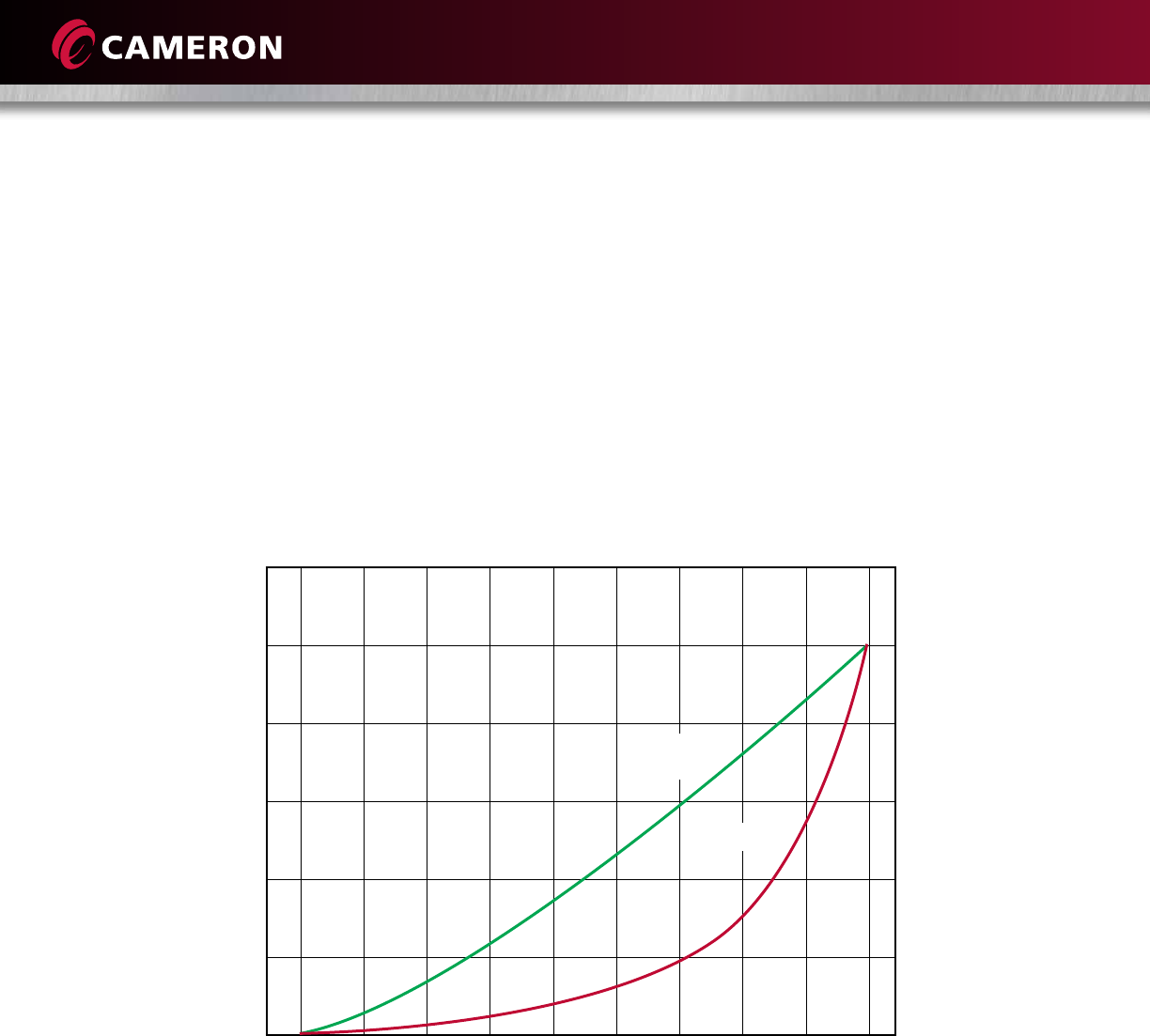
The following graph approximates the flow coefficient, CV or KV, of gate valves as a function of the valve stroke going
from closed to open. Note that this is an estimation only because of assumptions made in the valve stroke, as well as
unpredictable flow characteristics around the gate-seat bore in the partially open position.
Gate valves are intended for on-off service. Intermittent throttling such as pressure equalization service is acceptable.
Continuous throttling is not recommended. This information is provided only to facilitate the engineering of systems in
the transition between open and closed positions of the valves. One example might be to evaluate the possibility of water
hammer in liquid pipelines.
Partial Open Flow Characteristics (Through-Conduit Gate Valves)
Percent of Valve Stroke
120%
100%
80%
60%
40%
20%
0%
10% 20% 30% 40% 50% 60% 70% 80% 90% 100%
% of Total
Flow Area
% of CV
PARTIAL OPEN FLOW CHARACTERISTICS

23
WE BUILD IT. WE BACK IT.
CAMSERV™ Aftermarket Services for Valves and Actuation
Global Network and Local Support
Cameron is well-positioned to deliver total aftermarket
support, quickly and efficiently, with unmatched OEM
expertise. Our highly skilled engineers and technicians are
available around the clock, seven days a week, to respond
to customer queries, troubleshoot problems, and offer
reliable solutions.
Easily Accessible Parts and Spare Valves
• OEM spare valves, actuators, and parts
(including non-Cameron brands)
• Handling, storage, packaging, and delivery
• Dedicated stocking program
Comprehensive Aftermarket Services Portfolio
• Parts and spare valves
• Repair
• Field services
• Preventative maintenance
• Equipment testing and diagnostics
• Remanufacturing
• Asset preservation
• Customer property management
• Training and recertification services
• Warranty
Customized Total Valve CareSM (TVC) Programs
Customized asset management plans that optimize
uptime, availability, and dedicated services.
• Engineering consultancy
• Site management
• Flange management
• Startup and commissioning
• Spare parts and asset management
• Operational support
USA • CANADA • LATIN AMERICA • EUROPE • RUSSIA • AFRICA • MIDDLE EAST • ASIA PACIFIC


©2014 Cameron | GROVE, CAMERON, RING-O, TOM WHEATLEY, TK and WKM are registered brands of Cameron. CAMSERV, TBV, TEXSTEAM, Saf-T-Seal and Saf-T-Gard are trademarks
of Cameron. Total Valve Care is a service mark of Cameron. Viton and all other brands listed are trademarks of their respective companies. | SWP 1.M 06/14 AD01061V
3250 Briarpark Drive, Suite 300
Houston, TX 77042
USA
Toll Free 1 800 323 9160
Learn more about WKM gate valves at:
www.c-a-m.com/WKM/gate
WKM@c-a-m.com
HSE Policy Statement
At Cameron, we are committed ethically, financially and personally to a
working environment where no one gets hurt and nothing gets harmed.
H
E
A
L
T
H
S
A
F
E
T
Y
A
N
D
E
N
V
I
R
O
N
M
E
N
T
A
L
E
X
C
E
L
L
E
N
C
E
C
A
M
E
R
O
N
