Product Detail Manual WT
User Manual: wt
Open the PDF directly: View PDF ![]() .
.
Page Count: 36
- QUICK REFERENCE INDEX
- Table of Contents
- PRECAUTIONS
- PREPARATION
- NOISE, VIBRATION, AND HARSHNESS (NVH) TROUBLESHOOTING
- WHEEL
- WHEEL AND TIRE ASSEMBLY
- LOW TIRE PRESSURE WARNING SYSTEM
- CAN COMMUNICATION
- TROUBLE DIAGNOSES
- TROUBLE DIAGNOSIS FOR SELF-DIAGNOSTIC ITEMS
- TROUBLE DIAGNOSIS FOR SYMPTOMS
- Inspection 1: Warning Lamp Does Not Come On When Ignition Switch Is Turned On.
- Inspection 2: Warning Lamp Stays On When Ignition Switch Is Turned On.
- Inspection 3: Warning Lamp Flashes When Ignition Switch Is Turned On.
- Inspection 4: Hazard Warning Lamp Flashes When Ignition Switch Is Turned On.
- Inspection 5: “TIRE PRESSURE” Information In Display Unit Does Not Exist.
- Inspection 6: ID Registration Cannot Be Completed
- REMOVAL AND INSTALLATION
- SERVICE DATA AND SPECIFICATIONS (SDS)
- POWER SUPPLY ROUTING CIRCUIT
- ELECTRICAL UNITS
- SUPER MULTIPLE JUNCTION (SMJ)
- FUSE BLOCK-JUNCTION BOX (J/B)
- FUSE AND FUSIBLE LINK BOX

WT-1
ROAD WHEELS & TIRES
E SUSPENSION
CONTENTS
C
D
F
G
H
I
J
K
L
M
SECTION
A
B
WT
Revision: July 2006 2006 Quest
PRECAUTIONS .......................................................... 2
Precautions for Supplemental Restraint System
(SRS) “AIR BAG” and “SEAT BELT PRE-TEN-
SIONER” .................................................................. 2
PREPARATION ........................................................... 3
Special Service Tool ................................................. 3
Commercial Service Tools ........................................ 3
NOISE, VIBRATION, AND HARSHNESS (NVH)
TROUBLESHOOTING ................................................ 4
NVH Troubleshooting Chart ..................................... 4
WHEEL ....................................................................... 5
Inspection ................................................................. 5
WHEEL AND TIRE ASSEMBLY ................................. 6
PAX Run Flat Tires and Wheels ............................... 6
Conventional Tire and Wheel ................................... 6
BALANCING WHEELS ......................................... 6
ROTATION ............................................................ 7
LOW TIRE PRESSURE WARNING SYSTEM ............ 8
System Components ................................................ 8
System Description .................................................. 8
TRANSMITTER ..................................................... 8
REMOTE KEYLESS ENTRY RECEIVER ............. 9
BCM (BODY CONTROL MODULE) ...................... 9
COMBINATION METER ....................................... 9
DISPLAY UNIT ...................................................... 9
CAN COMMUNICATION ...........................................11
System Description .................................................11
TROUBLE DIAGNOSES .......................................... 12
Wiring Diagram — T/WARN — .............................. 12
Terminals and Reference Value for BCM ............... 13
ID Registration Procedure ...................................... 14
ID REGISTRATION WITH TRANSMITTER
ACTIVATION TOOL ............................................ 14
ID REGISTRATION WITHOUT TRANSMITTER
ACTIVATION TOOL ............................................ 16
Transmitter Wake Up Operation ............................. 18
WITH TRANSMITTER ACTIVATION TOOL ........ 18
CONSULT-II Function (BCM) ................................. 19
Self-Diagnosis ........................................................ 20
DESCRIPTION .................................................... 20
FUNCTION .......................................................... 20
How to Perform Trouble Diagnosis for Quick and
Accurate Repair ...................................................... 22
INTRODUCTION ................................................. 22
WORK FLOW ...................................................... 22
Preliminary Check .................................................. 23
Malfunction Code/Symptom Chart .......................... 24
TROUBLE DIAGNOSIS FOR SELF-DIAGNOSTIC
ITEMS ........................................................................ 26
Inspection 1: Transmitter or BCM ........................... 26
MALFUNCTION CODE NO. 21, 22, 23 OR 24
(DTC C1708, C1709, C1710 OR C1711) ............ 26
Inspection 2: Transmitter - 1 ................................... 26
MALFUNCTION CODE NO. 31, 32, 33, 34, 41,
42, 43, 44, 45, 46, 47 OR 48 ............................... 26
Inspection 3: Transmitter - 2 ................................... 27
MALFUNCTION CODE NO. 35, 36, 37 OR 38 ... 27
Inspection 4: Vehicle Speed Signal ........................ 28
MALFUNCTION CODE NO. 52 [DTC C1729] ..... 28
TROUBLE DIAGNOSIS FOR SYMPTOMS .............. 29
Inspection 1: Warning Lamp Does Not Come On
When Ignition Switch Is Turned On. ....................... 29
Inspection 2: Warning Lamp Stays On When Ignition
Switch Is Turned On. .............................................. 30
Inspection 3: Warning Lamp Flashes When Ignition
Switch Is Turned On. .............................................. 31
Inspection 4: Hazard Warning Lamp Flashes When
Ignition Switch Is Turned On. ................................. 32
Inspection 5: “TIRE PRESSURE” Information In
Display Unit Does Not Exist. ................................... 33
Inspection 6: ID Registration Cannot Be Completed ... 33
REMOVAL AND INSTALLATION ............................. 34
Transmitter ............................................................. 34
REMOVAL ........................................................... 34
INSTALLATION ................................................... 34
SERVICE DATA AND SPECIFICATIONS (SDS) ...... 36
Road Wheel ............................................................ 36
Tire ......................................................................... 36

WT-2
PRECAUTIONS
Revision: July 2006 2006 Quest
PRECAUTIONS PFP:00001
Precautions for Supplemental Restraint System (SRS) “AIR BAG” and “SEAT
BELT PRE-TENSIONER”
EES0022N
The Supplemental Restraint System such as “AIR BAG” and “SEAT BELT PRE-TENSIONER”, used along
with a front seat belt, helps to reduce the risk or severity of injury to the driver and front passenger for certain
types of collision. This system includes seat belt switch inputs and dual stage front air bag modules. The SRS
system uses the seat belt switches to determine the front air bag deployment, and may only deploy one front
air bag, depending on the severity of a collision and whether the front occupants are belted or unbelted.
Information necessary to service the system safely is included in the SRS and SB section of this Service Man-
ual.
WARNING:
●To avoid rendering the SRS inoperative, which could increase the risk of personal injury or death
in the event of a collision which would result in air bag inflation, all maintenance must be per-
formed by an authorized NISSAN/INFINITI dealer.
●Improper maintenance, including incorrect removal and installation of the SRS, can lead to per-
sonal injury caused by unintentional activation of the system. For removal of Spiral Cable and Air
Bag Module, see the SRS section.
●Do not use electrical test equipment on any circuit related to the SRS unless instructed to in this
Service Manual. SRS wiring harnesses can be identified by yellow and/or orange harnesses or
harness connectors.
PREPARATION
WT-3
C
D
F
G
H
I
J
K
L
M
A
B
WT
Revision: July 2006 2006 Quest
PREPARATION PFP:00002
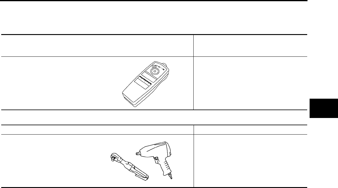
Special Service Tool
EES0021F
The actual shapes of Kent-Moore tools may differ from those of special service tools illustrated here.
Commercial Service Tools
EES0021G
Tool number
(Kent-Moore No.)
Tool name
Description
KV991 B1000
(J - 45295)
Transmitter activation tool
●Wake up
●ID registration
WEIA0144E
Tool name Description
Power tool Removing wheel nuts
PBIC0190E
WT-4
NOISE, VIBRATION, AND HARSHNESS (NVH) TROUBLESHOOTING
Revision: July 2006 2006 Quest
NOISE, VIBRATION, AND HARSHNESS (NVH) TROUBLESHOOTING PFP:00003
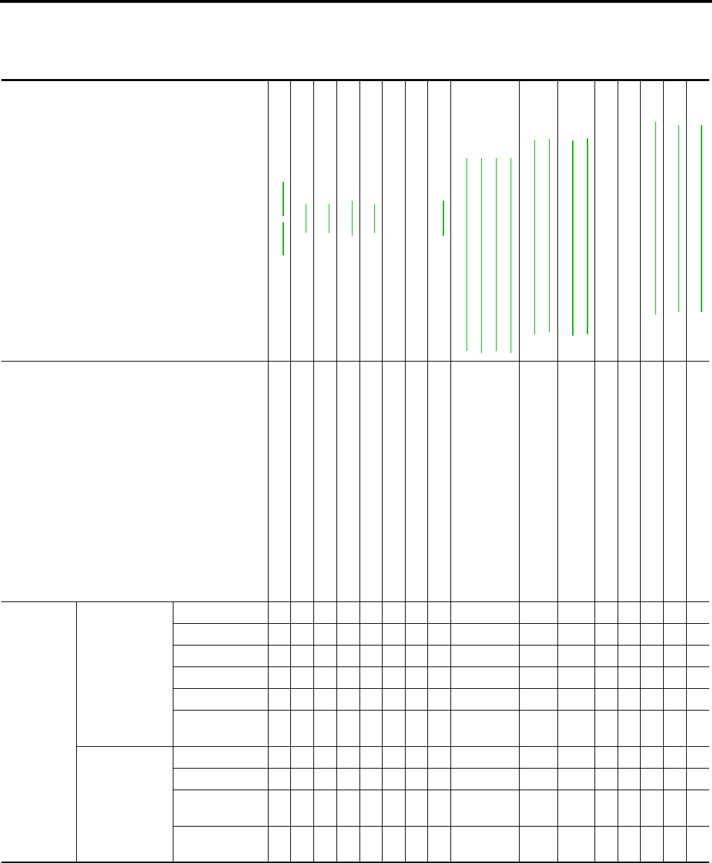
NVH Troubleshooting Chart
EES0021H
Use the chart below to help you find the cause of the symptom. If necessary, repair or replace these parts.
×: Applicable
Reference page
FAX-5, FSU-5
WT-5
WT-6
WT-36
WT-7
—
—
WT-36
FAX-4, "NVH Troubleshooting Chart" (FFD. 4 A/T),
RAX-4, "NVH Troubleshooting Chart" (RFD, 4 A/T)
FAX-4, "NVH Troubleshooting Chart" (FFD, 5 A/T),
RAX-4, "NVH Troubleshooting Chart" (RFD, 5 A/T)
FSU-4, "NVH Troubleshooting Chart" (FAX),
FAX-4, "NVH Troubleshooting Chart" (FSU)
RAX-4, "NVH Troubleshooting Chart" (RAX),
RSU-4, "NVH Troubleshooting Chart" (RSU)
Refer to TIRES in this chart.
Refer to ROAD WHEEL in this chart.
FAX-4, "NVH Troubleshooting Chart"
BR-5, "NVH Troubleshooting Chart"
PS-5, "NVH Troubleshooting Chart"
Possible cause and SUSPECTED PARTS
Improper installation, looseness
Out-of-round
Imbalance
Incorrect tire pressure
Uneven tire wear
Deformation or damage
Non-uniformity
Incorrect tire size
DIFFERENTIAL
FRONT AXLE AND FRONT SUSPENSION
REAR AXLE AND REAR SUSPENSION
TIRES
ROAD WHEEL
DRIVESHAFT
BRAKE
STEERING
Symptom
TIRES
Noise ××××××× × × × ××××
Shake ×××××× × × × ××××
Vibration ×× ××××
Shimmy ×××××××× × × × ××
shudder ×××××× × × × × ××
Poor quality
ride or handling ×××××× × × × ×
ROAD WHEEL
Noise ××× × × × × × ×××
Shake ××× × × × × ×××
Shimmy, shud-
der ××× × × × × ××
Poor quality
ride or handling ××× × × × ×
WHEEL
WT-5
C
D
F
G
H
I
J
K
L
M
A
B
WT
Revision: July 2006 2006 Quest
WHEEL PFP:40300
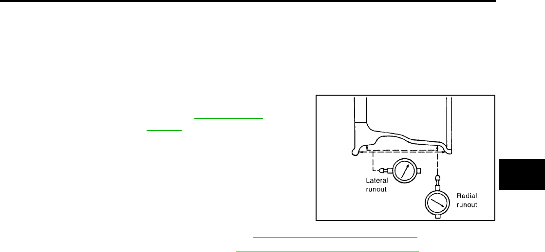
Inspection
EES0022L
1. Check tires for wear and improper inflation.
2. Check wheels for deformation, cracks and other damage. If deformed, remove wheel and check wheel
runout.
a. Remove tire from aluminum wheel and mount on a tire balance machine.
b. Set dial indicator as shown.
3. Check front wheel bearings for looseness. Refer to FAX-5, "FRONT WHEEL BEARING" .
4. Check front suspension for looseness. Refer to FSU-6, "FRONT SUSPENSION PARTS" .
Wheel runout
(Dial indicator value) : Refer to WT-36, "Road
Wheel" .
SFA975B
WT-6
WHEEL AND TIRE ASSEMBLY
Revision: July 2006 2006 Quest
WHEEL AND TIRE ASSEMBLY PFP:40300
PAX Run Flat Tires and Wheels
EES0022M
CAUTION:
●Servicing PAX run flat tires and wheels requires special tire equipment and training. DO NOT ser-
vice PAX Run Flat tires and wheels with conventional tire servicing equipment or damage to the
tire and wheel will result.
●If a PAX run flat tire and wheel [or transmitter (pressure sensor)] requires service, and the proper
servicing equipment is not available, then replace the complete PAX tire and wheel assembly.
Conventional Tire and Wheel
EES0021J
BALANCING WHEELS
1. Remove inner and outer balance weights from the road wheel.
CAUTION:
Be careful not to scratch the road wheel during removal.
2. Using releasing agent, remove double-faced adhesive tape from the road wheel.
CAUTION:
●Be careful not to scratch the road wheel during removal.
●After removing double-faced adhesive tape, wipe clean traces of releasing agent from the road
wheel.
3. Set road wheel on wheel balancer using the center hole as a guide. Start the tire balance machine.
●If a tire balance machine has adhesion balance weight mode settings and drive-in weight mode setting,
select and adjust a drive-in weight mode suitable for road wheels.
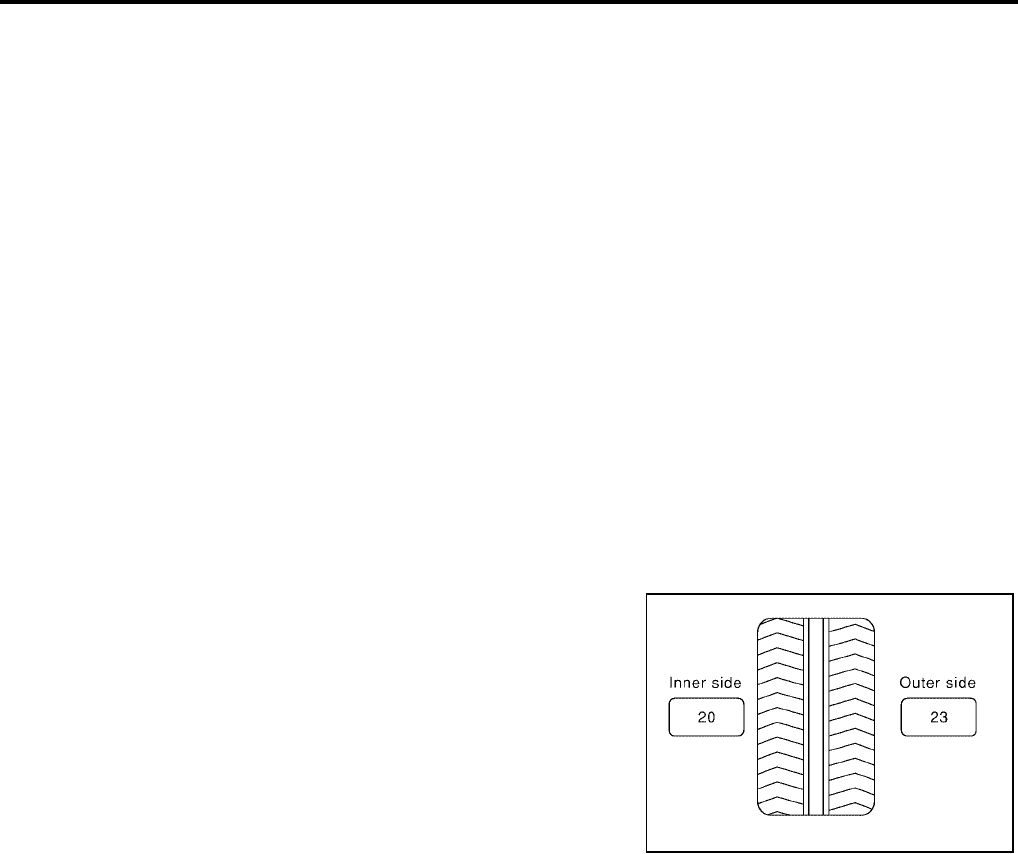
4. When inner and outer unbalance values are shown on the wheel
balancer indicator, multiply outer unbalance value by 1.6 to
determine balance weight that should be used. Select the outer
balance weight with a value closest to the calculated value
above and install it to the designated outer position of, or at the
designated angle in relation to the road wheel.
CAUTION:
●Do not install the inner balance weight before installing
the outer balance weight.
●Before installing the balance weight, be sure to clean the
mating surface of the road wheel.
Calculation:
Indicated unbalance value × 1.6 = balance weight to be installed
Calculation example:
23 g (0.81 oz) × 1.6 = 38.33 g (1.35 oz) = 40 g (1.41 oz) balance weight (closer to calculated balance
weight value)
NOTE:
The selected balance weight value must be the closest balance weight available to the calculated balance
weight value.
Example:
37.4 = 35 g (1.23 oz)
37.5 = 40 g (1.41 oz)
SMA054D
WHEEL AND TIRE ASSEMBLY
WT-7
C
D
F
G
H
I
J
K
L
M
A
B
WT
Revision: July 2006 2006 Quest
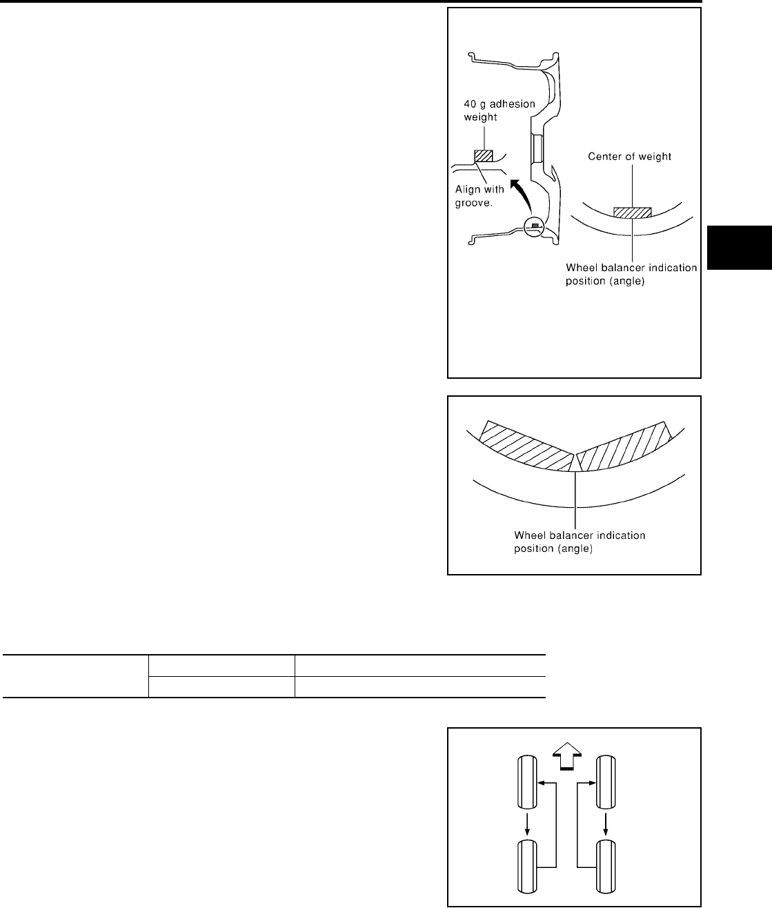
a. Install balance weight in the position shown.
b. When installing balance weight to road wheels, set it into the
grooved area on the inner wall of the road wheel as shown in the
figure so that the balance weight center is aligned with the wheel
balancer indication position (angle).
CAUTION:
●Always use Genuine NISSAN adhesion balance weights.
●Balance weights are not reusable; always replace with
new ones.
●Do not install more than three pieces of balance weight.
c. If calculated balance weight value exceeds 50 g (1.76 oz), install
two balance weight pieces in line with each other (as shown in
the figure).
CAUTION:
Do not install one balance weight piece on top of another.
5. Start wheel balancer again.
6. Install drive-in balance weight on inner side of road wheel in the
wheel balancer indication position (angle).
CAUTION:
Do not install more than two balance weights.
7. Start wheel balancer. Make sure that inner and outer residual
unbalance values are 5 g (0.18 oz) each or less.
●If either residual unbalance value exceeds 5 g (0.18 oz), repeat installation procedures.
Wheel balance (Maximum allowable unbalance):
ROTATION
●After rotating the tires, adjust the tire pressure.
●Retighten the wheel nuts when the vehicle has been driven for
1,000 km (600 miles) (also in cases of a flat tire, etc.).
CAUTION:
When installing wheels, tighten them diagonally by dividing
the work two to three times in order to prevent the wheels
from developing any distortion.
SMA055D
Maximum allowable
unbalance
Dynamic (At rim flange) Less than 5 g (0.18 oz) (per side)
Static (At rim flange) Less than 10 g (0.35 oz.)
SMA056D
Tightening torque
of wheel nut : 112 N·m (11 kg-m, 83 ft-lb)
WEIA0044E
WT-8
LOW TIRE PRESSURE WARNING SYSTEM
Revision: July 2006 2006 Quest
LOW TIRE PRESSURE WARNING SYSTEM PFP:40300
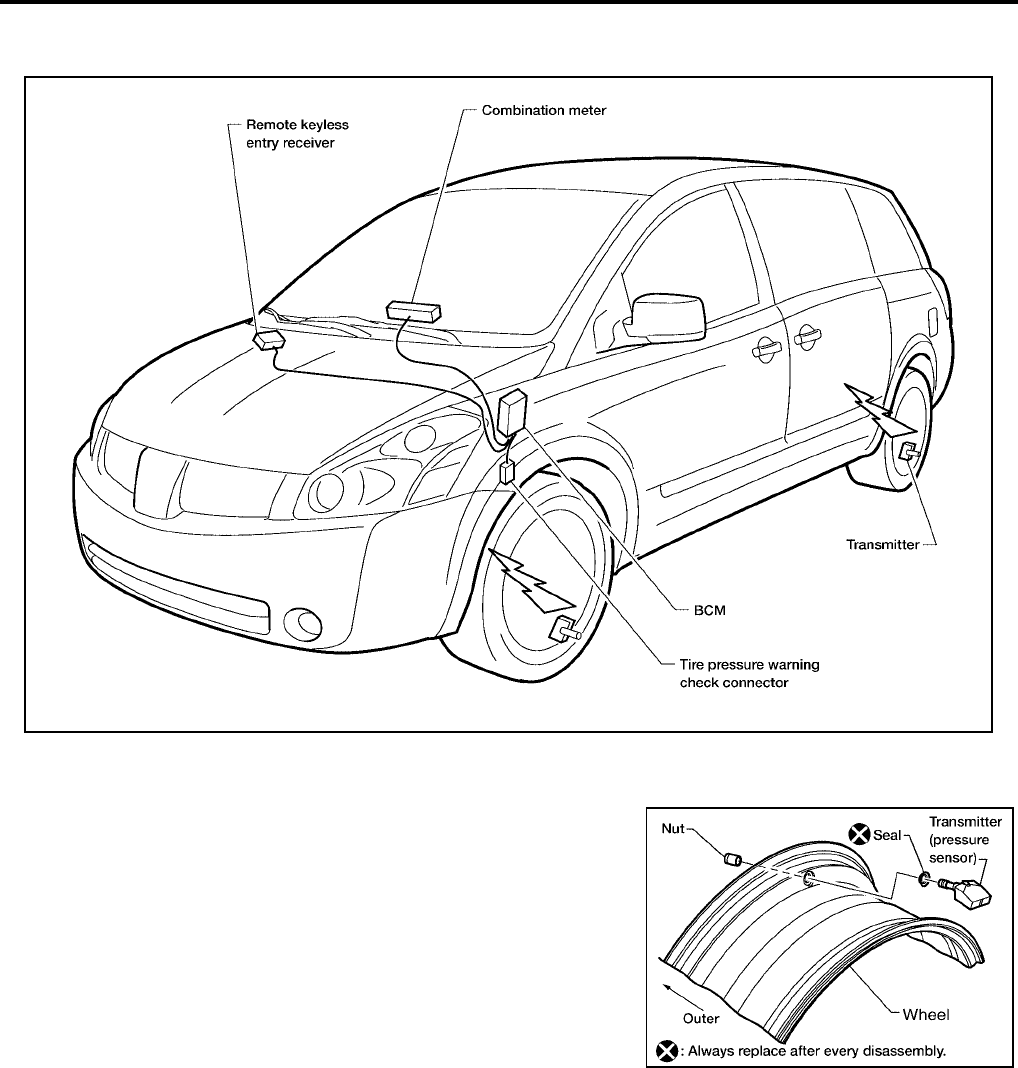
System Components
EES0021L
System Description
EES0021M
TRANSMITTER
A sensor-transmitter integrated with a valve is installed on a wheel,
and transmits a detected air pressure signal in the form of a radio
wave.
LEIA0051E
WEIA0137E
LOW TIRE PRESSURE WARNING SYSTEM
WT-9
C
D
F
G
H
I
J
K
L
M
A
B
WT
Revision: July 2006 2006 Quest
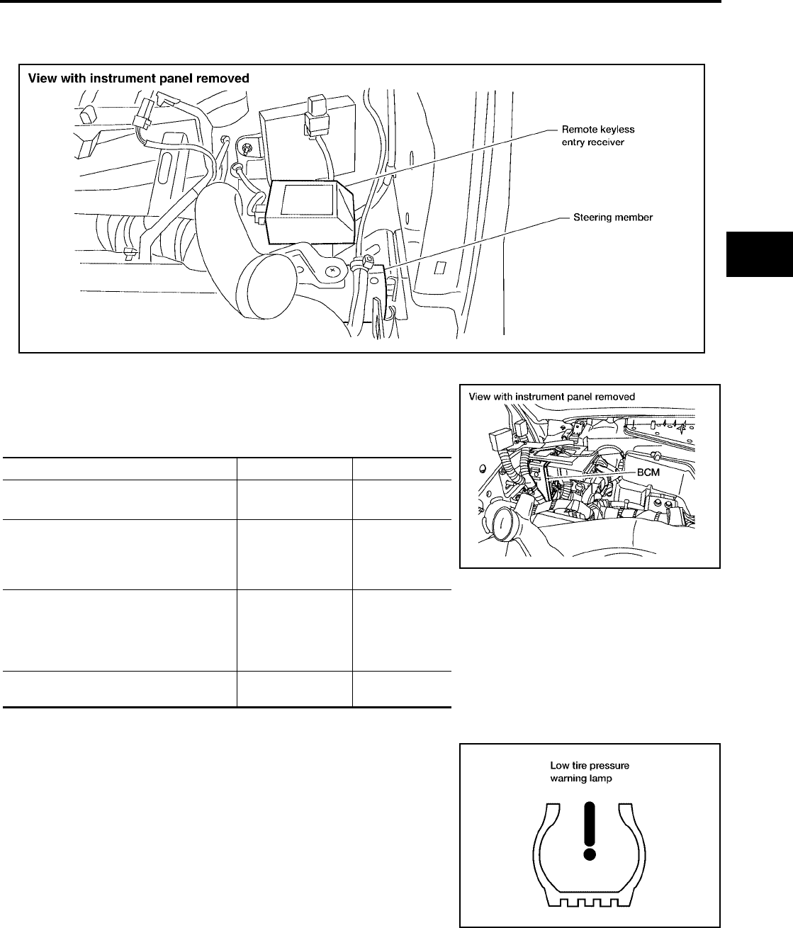
REMOTE KEYLESS ENTRY RECEIVER
The remote keyless entry receiver receives the air pressure signal transmitted by the transmitter in each
wheel.
BCM (BODY CONTROL MODULE)
The BCM reads the air pressure signal received by the remote key-
less entry receiver, and controls the combination meter warning
lamp and the buzzer operations as shown below. It also has a judge-
ment function to detect a system malfunction.
COMBINATION METER
The combination meter receives tire pressure status from the BCM
using CAN communication. When a low tire pressure condition is
sensed by the BCM, the combination meter low tire pressure warn-
ing lamp and buzzer are activated.
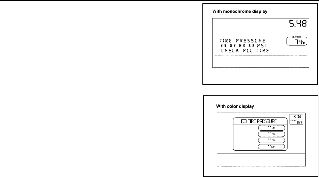
DISPLAY UNIT
Displays the air pressure of each tire.
LEIA0053E
Condition Warning lamp Buzzer
Less than 193 kPa (2.0 kg/cm2 , 28 psi)
[Flat tire] ON OFF
Less than 121 kPa (1.23 kg/cm2 , 17.5
psi)
[Flat tire]
(With PAX Run Flat tire and wheel)
Flash
(Twice per second)
ON
(10 seconds
after ignition
switch ON)
System malfunction
After key ON,
flashes once per
second for 1
minute, then stays
ON.
OFF
System normal On for 1 second
after ignition ON. OFF
LEIA0054E
LEIA0055E
WT-10
LOW TIRE PRESSURE WARNING SYSTEM
Revision: July 2006 2006 Quest
●After the ignition switch is turned ON, the pressure values are
not displayed until the data of each wheel is received.
WEIA0142E
WEIA0143E

CAN COMMUNICATION
WT-11
C
D
F
G
H
I
J
K
L
M
A
B
WT
Revision: July 2006 2006 Quest
CAN COMMUNICATION PFP:23710
System Description
EES0021N
Refer to LAN-24, "CAN COMMUNICATION" .
WT-12
TROUBLE DIAGNOSES
Revision: July 2006 2006 Quest
TROUBLE DIAGNOSES PFP:00004
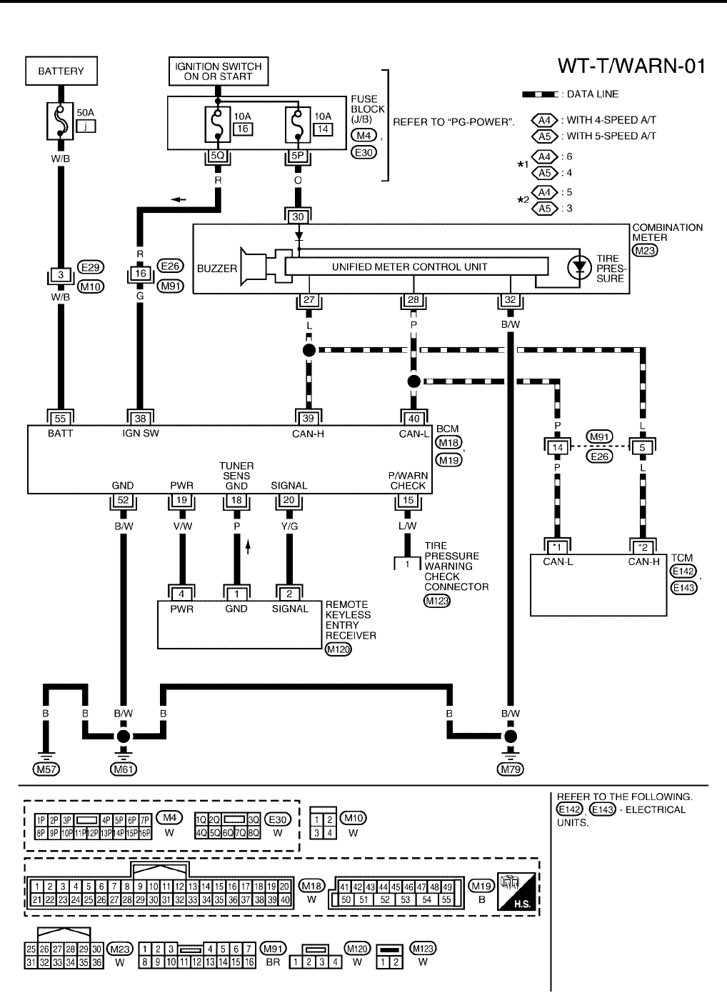
Wiring Diagram — T/WARN —
EES0021O
WEWA0043E
TROUBLE DIAGNOSES
WT-13
C
D
F
G
H
I
J
K
L
M
A
B
WT
Revision: July 2006 2006 Quest
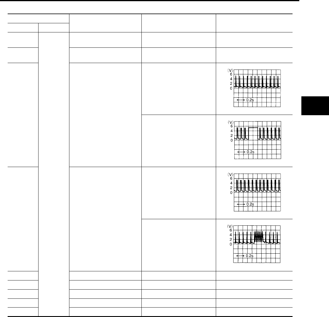
Terminals and Reference Value for BCM
EES0021P
( ) : Wire color
Terminal Item Condition Voltage (V)
(Approx.)
+–
15 (L/W)
Ground
Tire pressure warning check
connector —5V
18 (P) Remote keyless entry receiver
(Ground) —0V
19 (V/W) Remote keyless entry receiver
(Power supply)
Stand-by
Press any of the electronic
switches
20 (Y/G) Remote keyless entry receiver
(Signal)
Stand-by
Press any of the electronic
switches
38 (G) Ignition switch Ignition switch ON or START Battery voltage
39 (L) (CAN-H) ——
40 (P) (CAN-L) ——
52 (B/W) GND —0V
55 (W/B) Battery power supply —Battery voltage
OCC3879D
OCC3882D
OCC3881D
OCC3880D
WT-14
TROUBLE DIAGNOSES
Revision: July 2006 2006 Quest
ID Registration Procedure
EES0021Q
ID REGISTRATION WITH TRANSMITTER ACTIVATION TOOL
NOTE:
This procedure must be done after replacement of a low tire pressure warning transmitter or BCM.
New replacement transmitters are provided "asleep" and must first be "woken up" using Transmitter
Activation Tool J-45295 before ID registration can be performed.
CAUTION:
If CONSULT-II is used with no connection of CONSULT-II CONVERTER, malfunction might be detected
during self-diagnosis depending on control unit which carries out CAN communication.
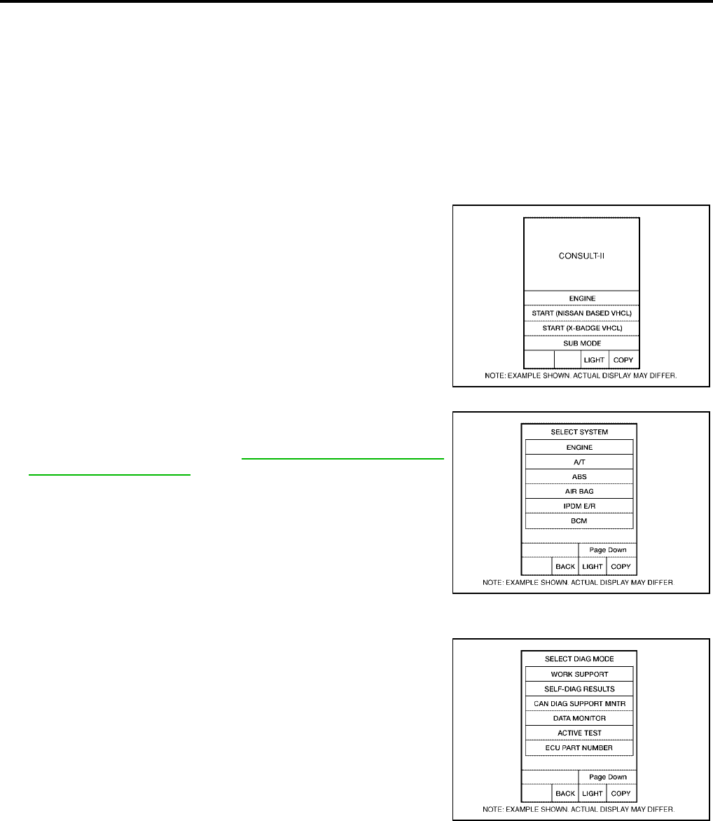
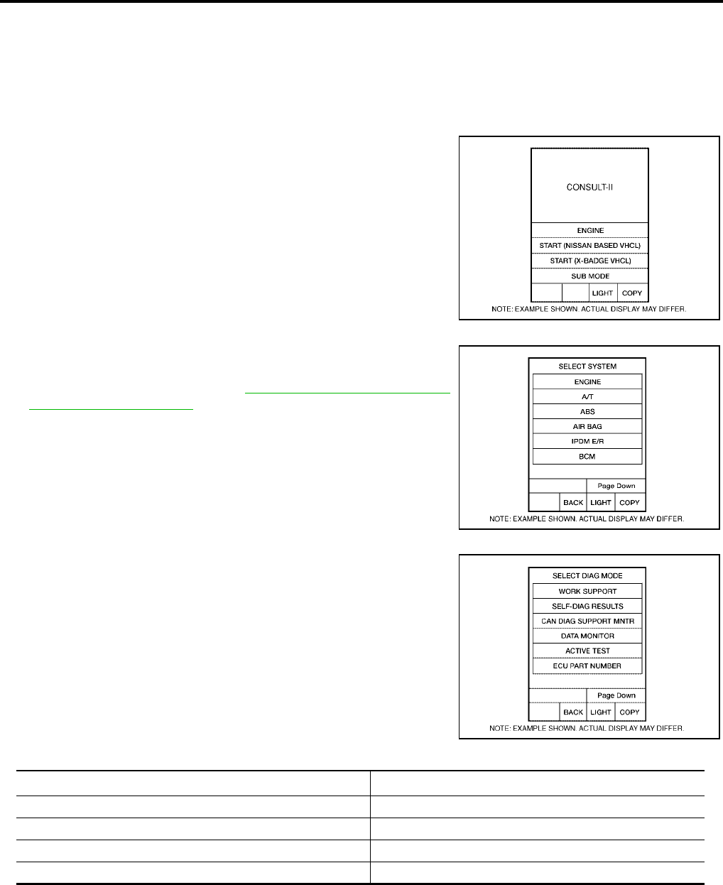
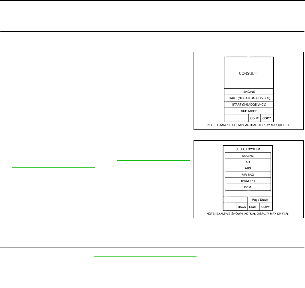
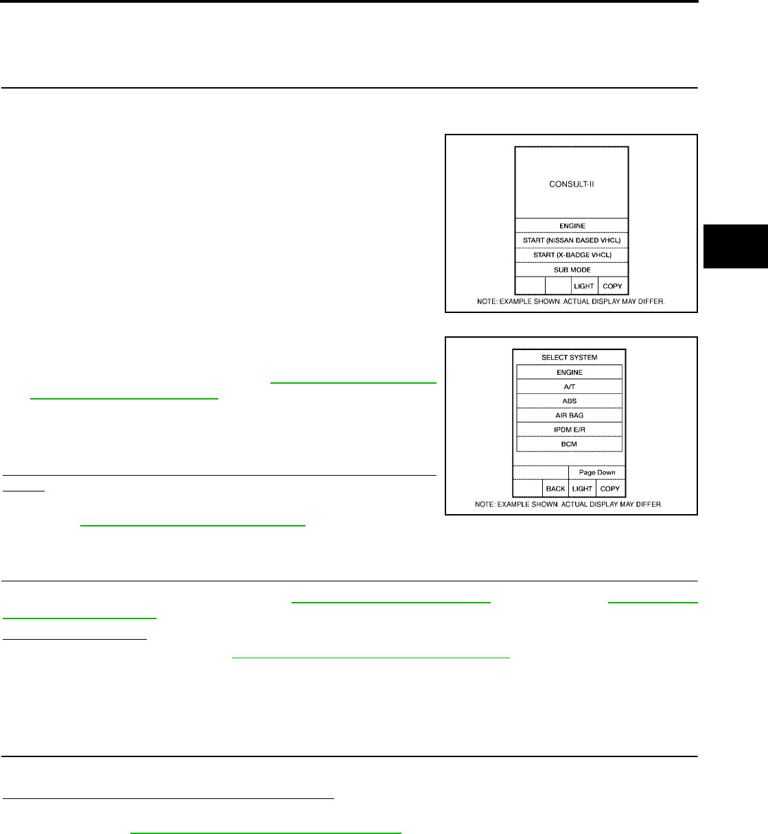
1. With the ignition switch OFF, connect CONSULT-II and CONSULT-II CONVERTER to the data link con-
nector, then turn the ignition switch ON.
2. Select "START (NISSAN BASED VHCL)".
3. Touch “BCM” on "SELECT SYSTEM" screen.
NOTE:
If "BCM" is not indicated, go to GI-38, "CONSULT-II Data Link
Connector (DLC) Circuit" .
4. Select “AIR PRESSURE MONITOR” on "SELECT TEST ITEM" screen.
5. Select “WORK SUPPORT” on "SELECT DIAG MODE" screen,
and select "ID REGIST".
BCIA0029E
BCIA0030E
BCIA0031E
TROUBLE DIAGNOSES
WT-15
C
D
F
G
H
I
J
K
L
M
A
B
WT
Revision: July 2006 2006 Quest
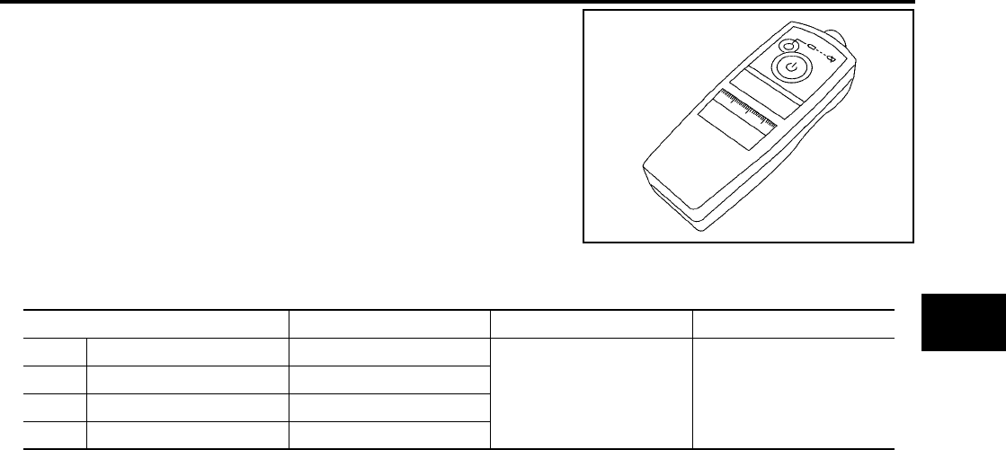
6. Push the transmitter activation tool against the tire near the front
left transmitter. Press the button for 5 seconds.
7. Register the IDs in order from FR LH, FR RH, RR RH and RR LH. When ID registration of each wheel has
been completed, a buzzer sounds and the hazard warning lamps flash.
8. After completing all ID registrations, press “END” to complete the procedure.
NOTE:
Be sure to register the IDs in order from FR LH, FR RH, RR RH, to RR LH, or the self-diagnostic results dis-
play will not function properly.
Tool number : (J-45295)
LEIA0036E
Activation tire position Buzzer Hazard warning lamp CONSULT-II
1 Front LH Once
2 times flashing
“YET”
↓
“DONE”
2Front RH 2 times
3Rear RH 3 times
4 Rear LH 4 times
WT-16
TROUBLE DIAGNOSES
Revision: July 2006 2006 Quest
ID REGISTRATION WITHOUT TRANSMITTER ACTIVATION TOOL
NOTE:
This procedure must be done after replacement of a low tire pressure warning transmitter or BCM.
New replacement transmitters are provided "asleep" and must first be "woken up" using Transmitter
Activation Tool J-45295 before ID registration can be performed.
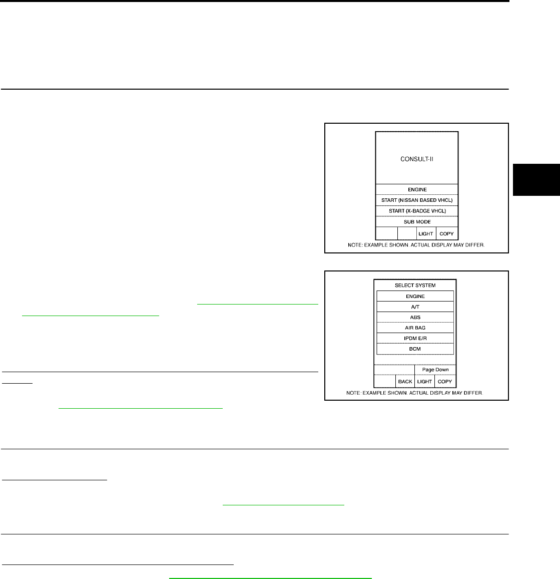
1. With the ignition switch OFF, connect CONSULT-II and CONSULT-II CONVERTER to the data link con-
nector, then turn the ignition switch ON.
2. Select "START (NISSAN BASED VHCL)".
3. Touch “BCM” on "SELECT SYSTEM" screen.
NOTE:
If "BCM" is not indicated, go to GI-38, "CONSULT-II Data Link
Connector (DLC) Circuit" .
4. Select “AIR PRESSURE MONITOR” on “SELECT TEST ITEM"
screen.
5. Select “WORK SUPPORT” on “SELECT DIAG MODE" screen,
and select "ID REGIST".
6. Adjust the tire pressure to the values shown in the table below
for ID registration, and drive the vehicle at 15 km/h (9.4 MPH) or
more for a few minutes.
7. After completing all ID registrations, press “END” to complete the procedure.
BCIA0029E
BCIA0030E
BCIA0031E
Tire position Tire pressure kPa (kg/cm2 , psi)
Front – Left 250 (2.5, 36)
Front – Right 230 (2.3, 33)
Rear – Right 210 (2.1, 30)
Rear – Left 190 (1.9, 27)

WT-18
TROUBLE DIAGNOSES
Revision: July 2006 2006 Quest
Transmitter Wake Up Operation
EES0021R
WITH TRANSMITTER ACTIVATION TOOL
NOTE:
This procedure must be done after replacement of a low tire pressure warning transmitter or BCM.
New replacement transmitters are provided "asleep" and must first be "woken up" using Transmitter
Activation Tool J-45295 before ID registration can be performed.
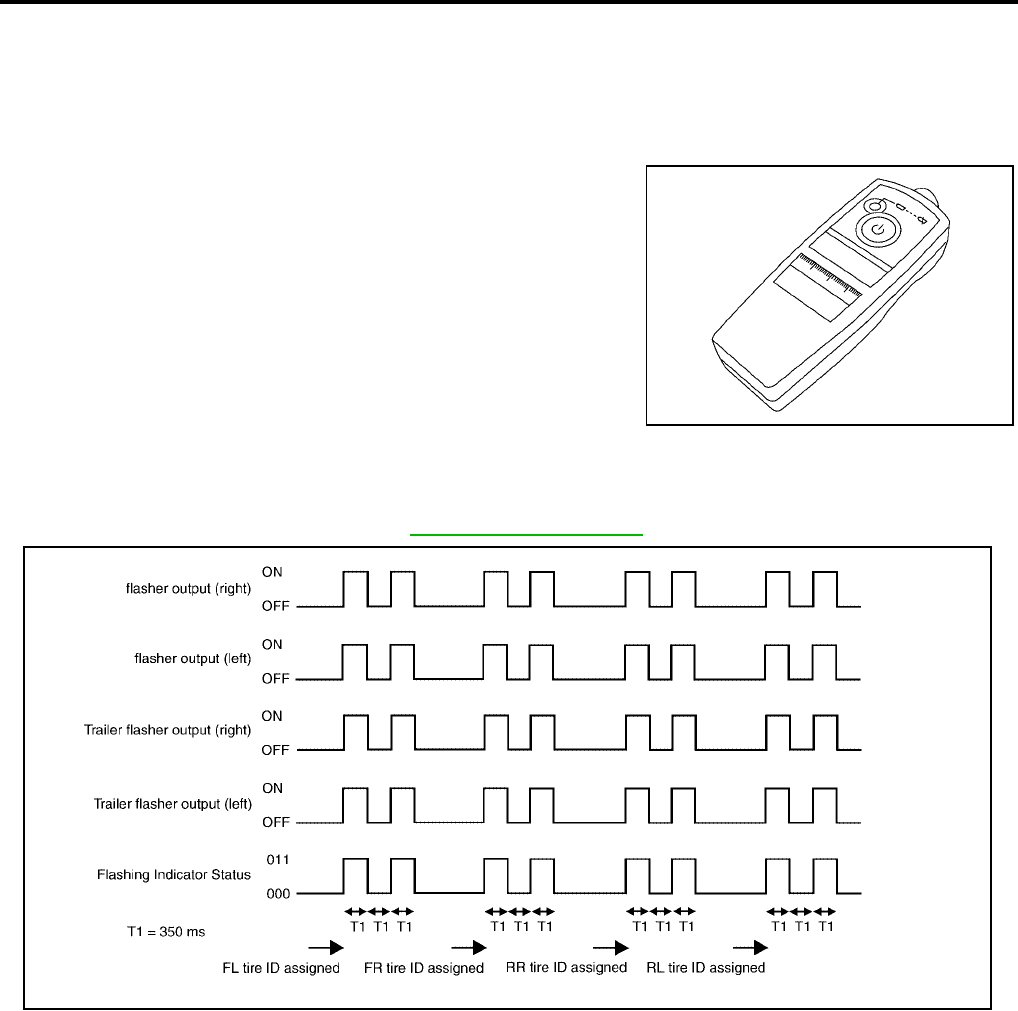
1. Push the transmitter activation tool against the tire near the front
left transmitter. Press the button for 5 seconds.
●With ignition switch ON, as the hazard warning lamp flashes
per the follow diagram, the respective transmitter then must
be woken up.
2. When the BCM finishes assigning each tire ID, the BCM flashes the hazard warning lamps and trailer
flasher lamps (if equipped) and sends flashing indicator status by CAN according to the following time
chart. Please see trailer flasher specification details of trailer flashing lamps since the BCM controls trailer
flasher lamps as brake lamps. Refer to LT-132, "TRAILER TOW" .
3. After completing wake up of all transmitters, make sure low tire pressure warning lamp goes out.
Tool number : (J-45295)
LEIA0036E
LEIA0059E

TROUBLE DIAGNOSES
WT-19
C
D
F
G
H
I
J
K
L
M
A
B
WT
Revision: July 2006 2006 Quest
CONSULT-II Function (BCM)
EES0021S
CONSULT-II can display each diagnostic item using the diagnostic test modes shown following.
BCM
diagnostic test item Diagnostic mode Description
Inspection by part
WORK SUPPORT
Supports inspections and adjustments. Commands are transmit-
ted to the BCM for setting the status suitable for required opera-
tion, input/output signals are received from the BCM and received
data is displayed.
DATA MONITOR Displays BCM input/output data in real time.
ACTIVE TEST Operation of electrical loads can be checked by sending drive sig-
nal to them.
SELF-DIAG RESULTS Displays BCM self-diagnosis results.
CAN DIAG SUPPORT MNTR The result of transmit/receive diagnosis of CAN communication
can be read.
ECU PART NUMBER BCM part number can be read.
CONFIGURATION Performs BCM configuration read/write functions.

WT-20
TROUBLE DIAGNOSES
Revision: July 2006 2006 Quest
Self-Diagnosis
EES0021T
DESCRIPTION
During driving, the low tire pressure warning system receives the signal transmitted from the transmitter
installed in each wheel, and gives alarms when the tire pressure becomes low. The control unit (BCM) for this
system has pressure judgement and trouble diagnosis functions.
FUNCTION
When the low tire pressure warning system detects low inflation pressure, the warning lamp in the combina-
tion meter comes on and the buzzer may sound (with PAX tires). To start the self-diagnostic results mode,
ground the terminal of the tire pressure warning check connector. The malfunction location is indicated by the
warning lamp flashing.
CONSULT-II Application to Low Tire Pressure Warning System
× : Applicable
– : Not applicable
Self-Diagnostic Results Mode
ITEM SELF-DIAGNOSTIC RESULTS DATA MONITOR
Front - Left transmitter ××
Front - Right transmitter ××
Rear - Left transmitter ××
Rear - Right transmitter ××
Warning lamp —×
Vehicle speed ××
Buzzer (in combination meter) —×
CAN Communication ×—
Diagnostic item Diagnostic item is detected when ··· Reference
page
PAX - FAIL - FL [C1730]
PAX - FAIL - FR [C1731]
PAX - FAIL - RR [C1732]
PAX - FAIL - RL [C1733]
Front-left tire pressure drops to 121 kPa (1.23 kg/cm2 , 17.5 psi) or less
Front-right tire pressure drops to 121 kPa (1.23 kg/cm2 , 17.5 psi) or less
Rear-right tire pressure drops to 121 kPa (1.23 kg/cm2 , 17.5 psi) or less
Rear-left tire pressure drops to 121 kPa (1.23 kg/cm2 , 17.5 psi) or less
—
FLAT - TIRE - FL [C1704]
FLAT - TIRE - FR [C1705]
FLAT - TIRE - RR [C1706]
FLAT - TIRE - RL [C1707]
Front-left tire pressure drops to 193 kPa (2.0 kg/cm2 , 28 psi) or less
Front-right tire pressure drops to 193 kPa (2.0 kg/cm2 , 28 psi) or less
Rear-right tire pressure drops to 193 kPa (2.0 kg/cm2 , 28 psi) or less
Rear-left tire pressure drops to 193 kPa (2.0 kg/cm2 , 28 psi) or less
—
[NO-DATA] - FL [C1708]
[NO-DATA] - FR [C1709]
[NO-DATA] - RR [C1710]
[NO-DATA] - RL [C1711]
Data from front-left transmitter cannot be received.
Data from front-right transmitter cannot be received.
Data from rear-right transmitter cannot be received.
Data from rear-left transmitter cannot be received.
WT-26,
"Inspection 1:
Transmitter or
BCM"
[CHECKSUM- ERR] - FL
[CHECKSUM- ERR] - FR
[CHECKSUM- ERR] - RR
[CHECKSUM- ERR] - RL
Checksum data from front-left transmitter is malfunctioning.
Checksum data from front-right transmitter is malfunctioning.
Checksum data from rear-right transmitter is malfunctioning.
Checksum data from rear-left transmitter is malfunctioning.
WT-26,
"Inspection 2:
Transmitter -
1"
[PRESSDATA- ERR] - FL
[PRESSDATA- ERR] - FR
[PRESSDATA- ERR] - RR
[PRESSDATA- ERR] - RL
Air pressure data from front-left transmitter is malfunctioning.
Air pressure data from front-right transmitter is malfunctioning.
Air pressure data from rear-right transmitter is malfunctioning.
Air pressure data from rear-left transmitter is malfunctioning.
WT-27,
"Inspection 3:
Transmitter -
2"
[CODE- ERR] - FL
[CODE- ERR] - FR
[CODE- ERR] - RR
[CODE- ERR] - RL
Function code data from front-left transmitter is malfunctioning.
Function code data from front-right transmitter is malfunctioning.
Function code data from rear-right transmitter is malfunctioning.
Function code data from rear-left transmitter is malfunctioning.
WT-26,
"Inspection 2:
Transmitter -
1"

TROUBLE DIAGNOSES
WT-21
C
D
F
G
H
I
J
K
L
M
A
B
WT
Revision: July 2006 2006 Quest
NOTE:
Before performing the self-diagnosis, be sure to register the ID or else the actual malfunction location may be different from that dis-
played on CONSULT-II.
Data Monitor Mode
NOTE:
Before performing the self-diagnosis, be sure to register the ID, or else the actual malfunction location may be different from that dis-
played on CONSULT-II.
[BATT - VOLT - LOW] - FL
[BATT - VOLT - LOW] - FR
[BATT - VOLT - LOW] - RR
[BATT - VOLT - LOW] - RL
Battery voltage of front-left transmitter drops.
Battery voltage of front-right transmitter drops.
Battery voltage of rear-right transmitter drops.
Battery voltage of rear-left transmitter drops.
WT-26,
"Inspection 2:
Transmitter -
1"
VHCL_SPEED_SIG_ERR [C1729] Vehicle speed signal is in error.
WT-28,
"Inspection 4:
Vehicle Speed
Signal"
Diagnostic item Diagnostic item is detected when ··· Reference
page
MONITOR CONDITION SPECIFICATION
VHCL SPEED Drive vehicle. Vehicle speed (km/h or MPH)
AIR PRESS FL
AIR PRESS FR
AIR PRESS RR
AIR PRESS RL
●Drive vehicle for a few minutes.
Tire pressure (kPa or psi)
or
●Ignition switch ON and activation tool
is transmitting activation signals.
ID REGST FL1
ID REGST FR1
ID REGST RR1
ID REGST RL1 Ignition switch ON
Registration ID: DONE
No registration ID: YET
WARNING LAMP Low tire pressure warning lamp on: ON
Low tire pressure warning lamp off: OFF
BUZZER Buzzer in combination meter on: ON
Buzzer in combination meter off: OFF
WT-22
TROUBLE DIAGNOSES
Revision: July 2006 2006 Quest
How to Perform Trouble Diagnosis for Quick and Accurate Repair
EES0021U
INTRODUCTION
●Before troubleshooting, verify customer complaints.
●If a vehicle malfunction is difficult to reproduce, harnesses, harness connectors or terminals may be mal-
functioning. Hold and shake these parts to make sure they are securely connected.
●When using a circuit tester to measure voltage or resistance of each circuit, be careful not to damage or
deform connector terminals.
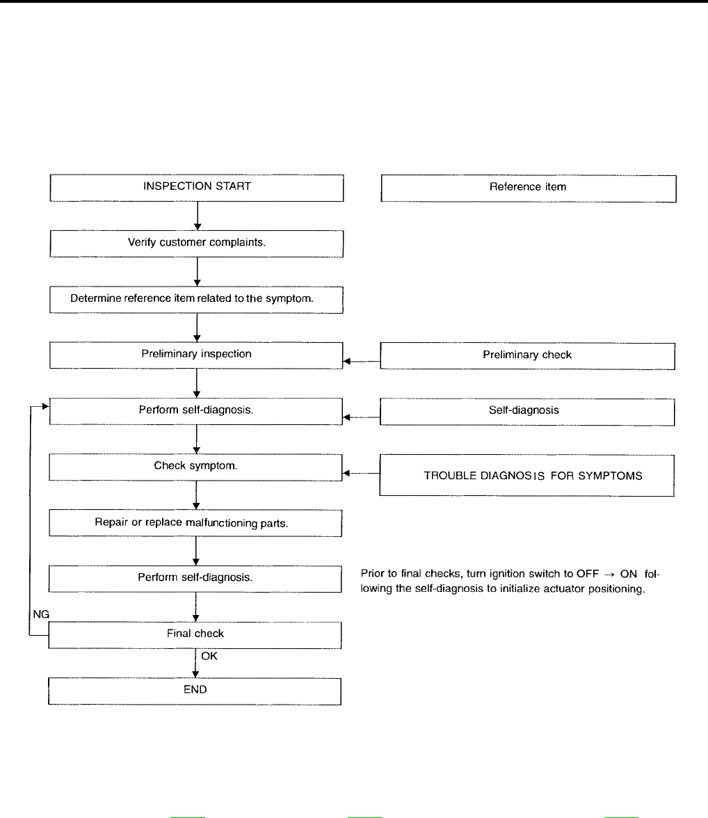
WORK FLOW
Preliminary check: WT-23 Self-diagnosis: WT-20 Trouble diagnosis for symptoms: WT-29
SEIA0100E

TROUBLE DIAGNOSES
WT-23
C
D
F
G
H
I
J
K
L
M
A
B
WT
Revision: July 2006 2006 Quest
Preliminary Check
EES0021V
BASIC INSPECTION
1. CHECK ALL TIRE PRESSURES
Check all tire pressures. Refer to WT-36, "Tire" .
OK or NG
OK >> GO TO 2.
NG >> Adjust tire pressure to specified value.
2. CHECK LOW TIRE PRESSURE WARNING LAMP ACTIVATION
1. Check low tire pressure warning lamp activation.
2. Does low tire pressure warning lamp activate for 1 second when ignition switch is turned ON?
Does warning lamp activate?
YES >> GO TO 3.
NO >> Check fuse and combination meter.
3. CHECK CONNECTOR
1. Disconnect BCM harness connector.
2. Check terminals for damage or loose connection.
3. Reconnect harness connector.
OK or NG
OK >> GO TO 4.
NG >> Repair or replace damaged parts.
4. CHECK TRANSMITTER ACTIVATION TOOL
Check transmitter activation tool battery.
OK or NG
OK >> Carry out self-diagnosis.
NG >> Replace transmitter activation tool battery.

WT-24
TROUBLE DIAGNOSES
Revision: July 2006 2006 Quest
Malfunction Code/Symptom Chart
EES0021W
Code/Symptom Malfunction part Reference
page
06
07
08
09
PAX fail FL. Pressure drops to 121 kPa (1.23 kg/cm2 , 17.5 psi) or less
PAX fail FR. Pressure drops to 121 kPa (1.23 kg/cm2 , 17.5 psi) or less
PAX fail RR. Pressure drops to 121 kPa (1.23 kg/cm2 , 17.5 psi) or less
PAX fail RL. Pressure drops to 121 kPa (1.23 kg/cm2 , 17.5 psi) or less
—
15
16
17
18
Front-left tire pressure drops to 193 kPa (2.0 kg/cm2 , 28 psi) or less
Front-right tire pressure drops to 193 kPa (2.0 kg/cm2 , 28 psi) or less
Rear-right tire pressure drops to 193 kPa (2.0 kg/cm2 , 28 psi) or less
Rear-left tire pressure drops to 193 kPa (2.0 kg/cm2 , 28 psi) or less
—
21
22
23
24
Transmitter no data (front - left)
Transmitter no data (front - right)
Transmitter no data (rear - right)
Transmitter no data (rear - left)
WT-26,
"Inspection 1:
Transmitter or
BCM"
31
32
33
34
Transmitter checksum error (front - left)
Transmitter checksum error (front - right)
Transmitter checksum error (rear - right)
Transmitter checksum error (rear - left)
WT-26,
"Inspection 2:
Transmitter -
1"
35
36
37
38
Transmitter pressure data error (front - left)
Transmitter pressure data error (front - right)
Transmitter pressure data error (rear - right)
Transmitter pressure data error (rear - left)
WT-27,
"Inspection 3:
Transmitter -
2"
41
42
43
44
Transmitter function code error (front - left)
Transmitter function code error (front - right)
Transmitter function code error (rear - right)
Transmitter function code error (rear - left)
WT-26,
"Inspection 2:
Transmitter -
1"
45
46
47
48
Transmitter battery voltage low (front - left)
Transmitter battery voltage low (front - right)
Transmitter battery voltage low (rear - right)
Transmitter battery voltage low (rear - left)
WT-26,
"Inspection 2:
Transmitter -
1"
52 Vehicle speed signal
WT-28,
"Inspection 4:
Vehicle Speed
Signal"
Low tire pressure warning lamp
does not come on when ignition
switch is turned on.
Fuse or combination meter
BCM connector or circuit
BCM
WT-29,
"Inspection 1:
Warning
Lamp Does
Not Come On
When Ignition
Switch Is
Turned On."
Low tire pressure warning lamp
stays on when ignition switch is
turned on.
Fuse or combination meter
BCM connector or circuit
BCM
WT-30,
"Inspection 2:
Warning
Lamp Stays
On When
Ignition
Switch Is
Turned On."
Low tire pressure warning lamp
flashes when ignition switch is
turned on.
BCM harness connector or circuit
BCM
Transmitter's mode off
ID registration not yet completed
WT-31,
"Inspection 3:
Warning
Lamp Flashes
When Ignition
Switch Is
Turned On."

TROUBLE DIAGNOSES
WT-25
C
D
F
G
H
I
J
K
L
M
A
B
WT
Revision: July 2006 2006 Quest
Hazard warning lamp flashes
when ignition switch is turned on.
BCM harness connector or circuit
BCM
WT-32,
"Inspection 4:
Hazard Warn-
ing Lamp
Flashes When
Ignition
Switch Is
Turned On."
“TIRE PRESSURE” information in
display unit does not exist.
Fuse
Display unit
BCM
WT-33,
"Inspection 5:
“TIRE PRES-
SURE” Infor-
mation In
Display Unit
Does Not
Exist."
ID registration cannot be com-
pleted.
Transmitter
Remote keyless entry receiver harness connector or circuit
Remote keyless entry receiver
WT-33,
"Inspection 6:
ID Registra-
tion Cannot
Be Com-
pleted"
Code/Symptom Malfunction part Reference
page

WT-26
TROUBLE DIAGNOSIS FOR SELF-DIAGNOSTIC ITEMS
Revision: July 2006 2006 Quest
TROUBLE DIAGNOSIS FOR SELF-DIAGNOSTIC ITEMS PFP:00000
Inspection 1: Transmitter or BCM
EES0021X
MALFUNCTION CODE NO. 21, 22, 23 OR 24 (DTC C1708, C1709, C1710 OR C1711)
1. CHECK CONTROL UNIT
Drive for several minutes. Check all tire pressures with CONSULT-II “DATA MONITOR ITEM”.
Are all tire pressures displayed as 0 kPa?
YES >> GO TO 2.
NO >> GO TO 3.
2. CHECK REMOTE KEYLESS ENTRY RECEIVER CONNECTOR
Check remote keyless entry receiver connector for damage or loose connections.
OK or NG
OK >> Replace BCM, then GO TO 3. Refer to BCS-20, "Removal and Installation of BCM" .
NG >> Repair or replace remote keyless entry receiver connector.
3. ID REGISTRATION
Carry out ID registration of all transmitters.
Is there a tire that cannot register ID?
YES >> Replace transmitter of the tire, then GO TO 5.
NO >> GO TO 4.
4. VEHICLE DRIVING
1. Drive at a speed of 40 km/h (25 MPH) or more for several minutes without stopping.
2. Check all tire pressures with CONSULT-II “DATA MONITOR ITEM” within 15 minutes after vehicle speed
becomes 17 km/h (11 MPH).
Does “DATA MONITOR ITEM” display tire pressure as normal without any warning lamp?
YES >> Inspection End.
NO >> GO TO 5.
5. ID REGISTRATION AND VEHICLE DRIVING
1. Carry out ID registration of all transmitters.
2. Drive at a speed of 40 km/h (25 MPH) or more for 3 minutes, and then drive the vehicle at any speed for
10 minutes. Then check all tire pressures with CONSULT-II “DATA MONITOR ITEM” within 5 minutes.
Does “DATA MONITOR ITEM” display tire pressure as normal without any warning lamp?
YES >> Inspection End.
NO >> GO TO the inspection applicable to DTC.
Inspection 2: Transmitter - 1
EES0021Y
MALFUNCTION CODE NO. 31, 32, 33, 34, 41, 42, 43, 44, 45, 46, 47 OR 48
1. ID REGISTRATION (CORRECTION OF TRANSMITTER LOCATION)
1. Carry out ID registration of all transmitters.
2. Drive at a speed of 40 km/h (25 MPH) or more for 3 minutes, and then drive the vehicle at any speed for
10 minutes.
>> GO TO 2.
TROUBLE DIAGNOSIS FOR SELF-DIAGNOSTIC ITEMS
WT-27
C
D
F
G
H
I
J
K
L
M
A
B
WT
Revision: July 2006 2006 Quest
2. REPLACE TRANSMITTER
1. Check low tire pressure warning lamp again for flashing, replace malfunctioning transmitter.
2. Carry out ID registration of all transmitters.
Can ID registration of all transmitters be completed?
YES >> GO TO 3.
NO >> GO TO Inspection 1. Refer to WT-26, "Inspection 1: Transmitter or BCM" .
3. VEHICLE DRIVING
Drive at a speed of 40 km/h (25 MPH) or more for 3 minutes, and then drive the vehicle at any speed for 10
minutes. Then check all tire pressures with CONSULT-II “DATA MONITOR ITEM” within 5 minutes.
Does “DATA MONITOR ITEM” display tire pressure as normal without any warning lamp?
YES >> Inspection End.
NO >> Replace malfunctioning transmitter, and perform “Step 3” again.
Inspection 3: Transmitter - 2
EES0021Z
MALFUNCTION CODE NO. 35, 36, 37 OR 38
1. CHECK ALL TIRE PRESSURES
Check all tire pressures. Refer to WT-36, "Tire" .
Are there any tires with pressure of 64 psi or more?
NO >> GO TO 2.
YES >> Adjust tire pressure to specified value.
2. VEHICLE DRIVING
1. Carry out ID registration of all transmitters.
2. Drive at a speed of 40 km/h (25 MPH) or more for several minutes without stopping.
Check all tire pressures with CONSULT-II “DATA MONITOR ITEM” within 15 minutes after vehicle speed
becomes 17 km/h (11 MPH).
>> Replace transmitter with new one if “DATA MONITOR ITEM” displays 64 psi or more. Then GO
TO 3.
3. ID REGISTRATION AND VEHICLE DRIVING
●Carry out ID registration of all transmitters.
●Drive at a speed of 40 km/h (25 MPH) or more for 3 minutes, and then drive the vehicle at any speed for
10 minutes. Then check all tire pressures with CONSULT-II “DATA MONITOR ITEM” within 5 minutes.
Does “DATA MONITOR ITEM” display tire pressure as normal without any warning lamp?
YES >> Inspection End.
NO >> GO TO the inspection applicable to DTC.
WT-28
TROUBLE DIAGNOSIS FOR SELF-DIAGNOSTIC ITEMS
Revision: July 2006 2006 Quest
Inspection 4: Vehicle Speed Signal
EES00220
MALFUNCTION CODE NO. 52 [DTC C1729]
1. SELF-DIAGNOSTIC RESULT CHECK
1. With the ignition switch OFF, connect CONSULT-II and CONSULT-II CONVERTER to the data link con-
nector, then turn the ignition switch ON.
2. Select “START (NISSAN BASED VHCL)”.
3. Select "BCM" on “SELECT SYSTEM” screen.
NOTE:
If the BCM is not indicated, refer to GI-38, "CONSULT-II Data
Link Connector (DLC) Circuit" .
4. Select "BCM" on "SELECT TEST ITEM" screen, and select
"SELF-DIAG RESULTS".
5. Check display contents in self-diagnostic results.
Is " CAN COMM CIRCUIT" displayed in the self-diagnosis display
items?
YES >> Malfunction in CAN communication system. GO TO
LAN-24, "CAN COMMUNICATION" .
NO >> GO TO 2.
2. CHECK BCM
Perform BCM diagnosis. Refer to BCS-11, "CONSULT-II OPERATION" .
Inspection results OK?
OK >> Perform Vehicle Speed Sensor Inspection. Refer to AT-122, "Diagnostic Procedure" for 4-speed
A/T or AT-477, "Diagnostic Procedure" for 5-speed A/T.
NG >> Replace BCM. Refer to BCS-20, "Removal and Installation of BCM" .
BCIA0029E
BCIA0030E
TROUBLE DIAGNOSIS FOR SYMPTOMS
WT-29
C
D
F
G
H
I
J
K
L
M
A
B
WT
Revision: July 2006 2006 Quest
TROUBLE DIAGNOSIS FOR SYMPTOMS PFP:00007
Inspection 1: Warning Lamp Does Not Come On When Ignition Switch Is Turned
On.
EES00221
DIAGNOSTIC PROCEDURE
1. SELF-DIAGNOSTIC RESULT CHECK
1. With the ignition switch OFF, connect CONSULT-II and CONSULT-II CONVERTER to the data link con-
nector, then turn the ignition switch ON.
2. Select “START (NISSAN BASED VHCL)”.
3. Select "BCM" on “SELECT SYSTEM” screen.
NOTE:
If the BCM is not indicated, refer to GI-38, "CONSULT-II Data
Link Connector (DLC) Circuit" .
4. Select "BCM" on "SELECT TEST ITEM" screen, and select
"SELF-DIAG RESULTS".
5. Check display contents in self-diagnostic results.
Is "CAN COMM CIRCUIT " displayed in the self-diagnosis display
items?
YES >> Malfunction in CAN communication system. GO TO
LAN-24, "CAN COMMUNICATION" .
NO >> GO TO 2.
2. CHECK COMBINATION METER
Check combination meter operation.
Inspection results OK?
OK >> GO TO 3.
NG >> Check combination meter. Refer to DI-7, "Combination Meter" .
3. CHECK LOW TIRE PRESSURE WARNING LAMP
Disconnect BCM harness connector.
Does the low tire pressure warning lamp activate?
YES >> Replace BCM. Refer to BCS-20, "Removal and Installation of BCM" .
NO >> Check combination meter and repair or replace.
BCIA0029E
BCIA0030E
WT-30
TROUBLE DIAGNOSIS FOR SYMPTOMS
Revision: July 2006 2006 Quest
Inspection 2: Warning Lamp Stays On When Ignition Switch Is Turned On.
EES00222
DIAGNOSTIC PROCEDURE
1. CHECK CONNECTOR
1. Turn ignition switch OFF.
2. Disconnect BCM harness connectors M18, M19 and M20.
3. Check terminals for damage or loose connections.
Inspection results OK?
OK >> GO TO 2.
NG >> Repair or replace damaged parts.
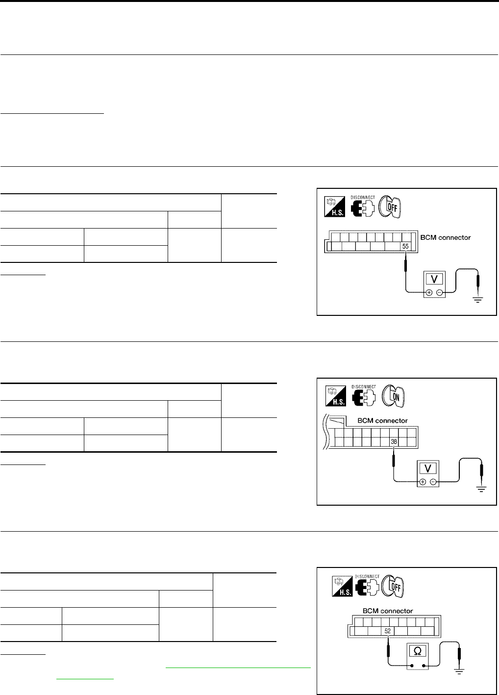
2. CHECK POWER SUPPLY CIRCUIT (BAT)
Check voltage between BCM harness connector M19 terminal 55 and ground.
1.
OK or NG
OK >> GO TO 3.
NG >> Check BCM power supply circuit for open or short.
3. CHECK POWER SUPPLY CIRCUIT (IGN)
1. Turn ignition switch ON.
2. Check voltage between BCM harness connector M18 terminal 38 and ground.
OK or NG
OK >> GO TO 4.
NG >> Check BCM power supply circuit for open or short.
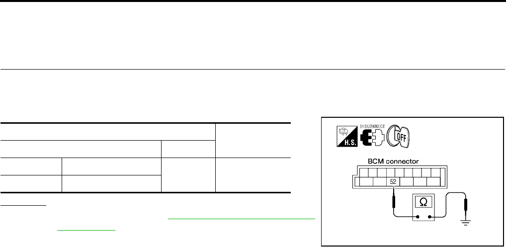
4. CHECK GROUND CIRCUIT
1. Turn ignition switch OFF.
2. Check continuity between BCM harness connector M19 terminal 52 and ground.
OK or NG
OK >> Replace BCM. Refer to BCS-20, "Removal and Installa-
tion of BCM" .
NG >> Repair or replace BCM ground circuit.
Terminals Voltage
(Approx.)
(+) (–)
Connector Terminal Ground 12V
M19 55
WEIA0039E
Terminals Voltage
(Approx.)
(+) (–)
Connector Terminal Ground 12V
M18 38
WEIA0038E
Terminals Continuity
(+) (–)
Connector Terminal Ground Yes
M19 52
WKIA2973E
TROUBLE DIAGNOSIS FOR SYMPTOMS
WT-31
C
D
F
G
H
I
J
K
L
M
A
B
WT
Revision: July 2006 2006 Quest
Inspection 3: Warning Lamp Flashes When Ignition Switch Is Turned On.
EES00223
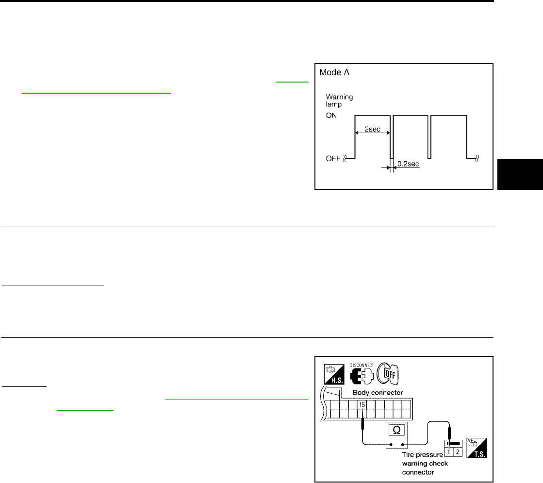
NOTE:
If warning lamp flashes as shown, the system is normal.
Flash Mode A
●This mode shows transmitter status is OFF-mode.
Carry out transmitter wake up operation. Refer to WT-18,
"Transmitter Wake Up Operation" .
DIAGNOSTIC PROCEDURE
1. CHECK CONNECTOR
1. Turn ignition switch OFF.
2. Disconnect BCM harness connectors M18, M19 and M20.
3. Check terminals for damage or loose connections.
Inspection results OK?
OK >> GO TO 2.
NG >> Repair or replace damaged parts.
2. CHECK TIRE PRESSURE WARNING CHECK CONNECTOR CIRCUIT
Check continuity between BCM harness connector M18 terminal 15 and check connector M123 terminal 1.
OK or NG
OK >> Replace BCM. Refer to BCS-20, "Removal and Installa-
tion of BCM" .
NG >> Repair or replace harness connector.
SEIA0347E
Continuity should exist.
WEIA0041E
WT-32
TROUBLE DIAGNOSIS FOR SYMPTOMS
Revision: July 2006 2006 Quest
Inspection 4: Hazard Warning Lamp Flashes When Ignition Switch Is Turned
On.
EES00224
DIAGNOSTIC PROCEDURE
1. CHECK GROUND CIRCUIT
1. Turn ignition switch OFF.
2. Disconnect BCM harness connector M19.
3. Check continuity between BCM harness connector M19 terminal 52 and ground.
OK or NG
OK >> Replace BCM. Refer to BCS-20, "Removal and Installa-
tion of BCM" .
NG >> Repair or replace BCM ground circuit.
Terminals Continuity
(+) (–)
Connector Terminal Ground Yes
M19 52
WKIA2973E
TROUBLE DIAGNOSIS FOR SYMPTOMS
WT-33
C
D
F
G
H
I
J
K
L
M
A
B
WT
Revision: July 2006 2006 Quest
Inspection 5: “TIRE PRESSURE” Information In Display Unit Does Not Exist.
EES00225
DIAGNOSTIC PROCEDURE
1. SELF-DIAGNOSTIC RESULT CHECK
1. With the ignition switch OFF, connect CONSULT-II and CONSULT-II CONVERTER to the data link con-
nector, then turn the ignition switch ON.
2. Select “START (NISSAN BASED VHCL)”.
3. Select "BCM" on “SELECT SYSTEM” screen.
NOTE:
If the BCM is not indicated, refer to GI-38, "CONSULT-II Data
Link Connector (DLC) Circuit" .
4. Select "BCM" on "SELECT TEST ITEM" screen, and select
"SELF-DIAG RESULTS".
5. Check display contents in self-diagnostic results.
Is "CAN COMM CIRCUIT" displayed in the self-diagnosis display
items?
YES >> Malfunction in CAN communication system. GO TO
LAN-24, "CAN COMMUNICATION" .
NO >> GO TO 2.
2. CHECK DISPLAY UNIT
Perform display unit self-diagnosis. Refer to AV-130, "Self-Diagnosis Mode" without NAVI or AV-194, "Self-
Diagnosis Mode (NAVI)" with NAVI.
Inspection results OK?
OK >> Replace BCM. Refer to BCS-20, "Removal and Installation of BCM" .
NG >> Repair or replace malfunctioning parts.
Inspection 6: ID Registration Cannot Be Completed
EES00226
DIAGNOSTIC PROCEDURE
1. ID REGISTRATION (ALL)
Carry out ID registration of all transmitters.
Can ID registration of all transmitters be completed?
YES >> Inspection End.
NO >> GO TO WT-26, "Inspection 1: Transmitter or BCM" .
BCIA0029E
BCIA0030E
WT-34
REMOVAL AND INSTALLATION
Revision: July 2006 2006 Quest
REMOVAL AND INSTALLATION PFP:00000
Transmitter
EES00227
CAUTION:
●Servicing PAX run flat tires and wheels requires special tire equipment and training. DO NOT ser-
vice PAX Run Flat tires and wheels with conventional tire servicing equipment or damage to the
tire and wheel will result.
●If a PAX run flat tire and wheel [or transmitter (pressure sensor)] requires service, and the proper
servicing equipment is not available, then replace the complete PAX tire and wheel assembly.
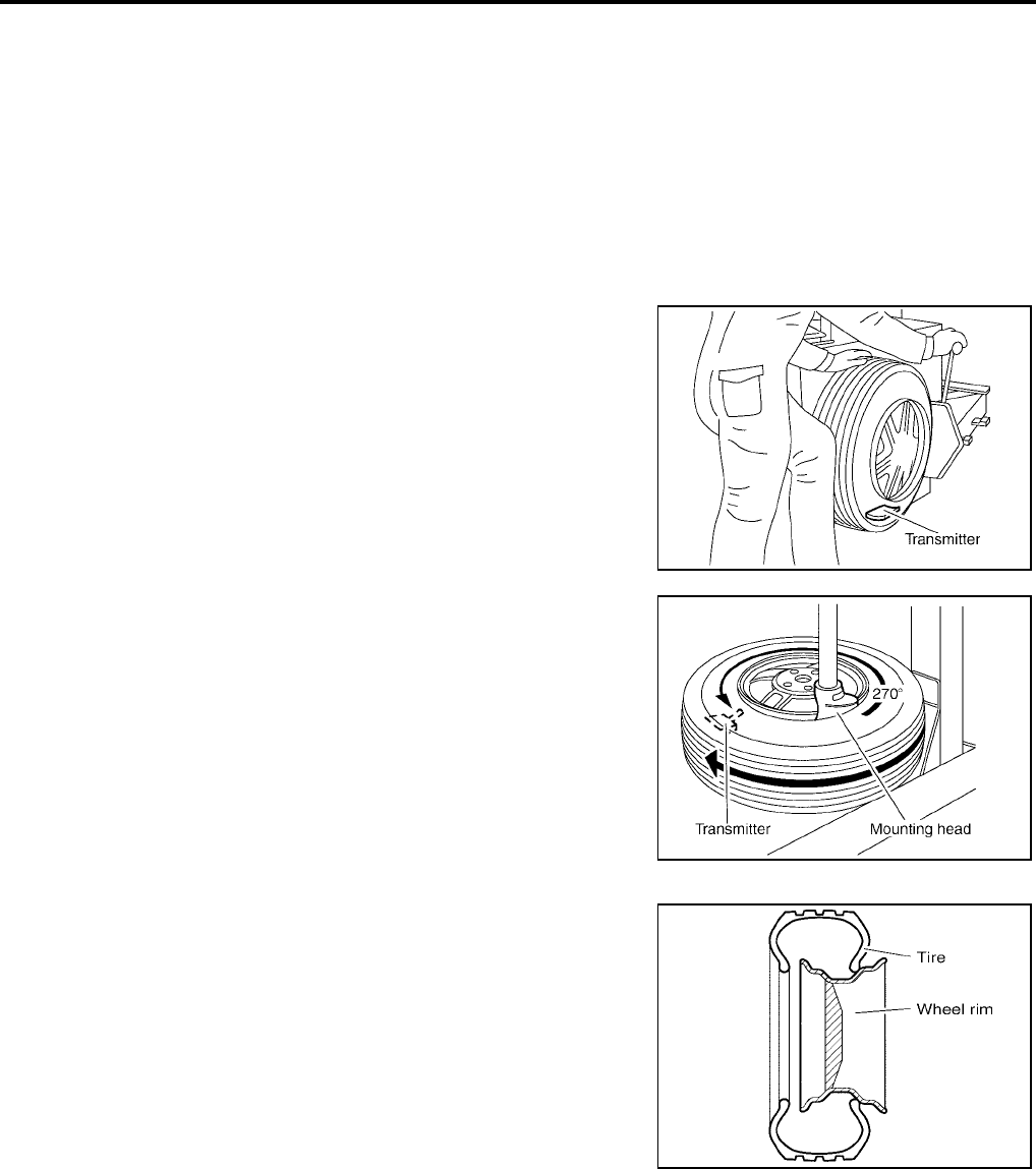
REMOVAL
1. Deflate tire. Unscrew transmitter retaining nut and allow transmitter to fall into tire.
2. Gently bounce tire so that transmitter falls to bottom of tire.
Place on tire changing machine and break both tire beads
ensuring that the transmitter remains at the bottom of the tire.
3. Turn tire so that valve hole is at bottom and bounce so that
transmitter is near valve hole. Carefully lift tire onto turntable and
position valve hole (and transmitter) 270 degrees from mount-
ing/dismounting head.
4. Lubricate tire well and remove first side of the tire. Reach inside
the tire and remove the transmitter.
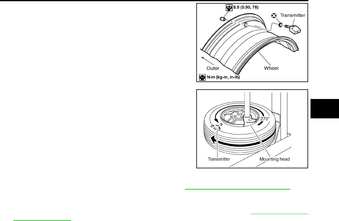
INSTALLATION
1. Put first side of tire onto rim.
SEIA0047E
WEIA0046E
SEIA0049E
REMOVAL AND INSTALLATION
WT-35
C
D
F
G
H
I
J
K
L
M
A
B
WT
Revision: July 2006 2006 Quest
2. Mount transmitter on rim and tighten nut to the specification
shown.
3. Place wheel on turntable of tire machine. Ensure that transmitter
is 270 degrees from mounting head when second side of tire is
fitted.
NOTE:
Do not touch transmitter at mounting head.
4. Lubricate tire well, and install second side of tire as normal. Ensure that tire does not rotate relative to rim.
5. Inflate tire and balance the wheel and tire assembly. Refer to WT-6, "Conventional Tire and Wheel" .
6. Install wheel and tire assembly in appropriate wheel position on vehicle.
NOTE:
If replacing transmitter, transmitter wake up operation must be performed. Refer to WT-18, "Transmitter
Wake Up Operation" .
WEIA0045E
WEIA0046E
WT-36
SERVICE DATA AND SPECIFICATIONS (SDS)
Revision: July 2006 2006 Quest
SERVICE DATA AND SPECIFICATIONS (SDS) PFP:00030
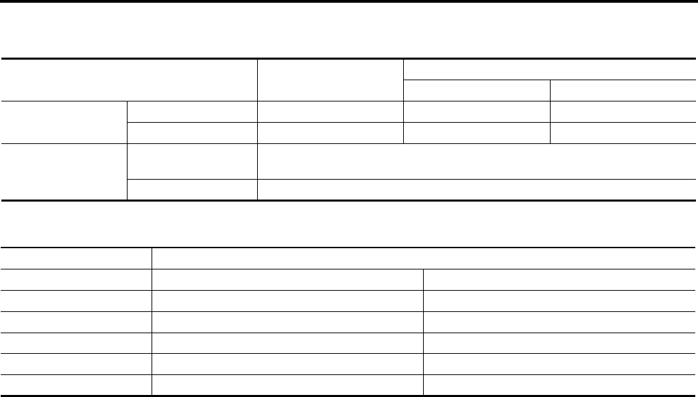
Road Wheel
EES0022G
Tire
EES0022H
Unit: kPa (kg/cm2 , psi)
*: D or R depending on manufacturer.
Wheel type Aluminum Steel
Inside Outside
Maximum radial
runout limit
Lateral mm (in) 0.3 (0.012) or less 1.0 (0.039) or less 0.9 (0.035) or less
Radial mm (in) 0.3 (0.012) or less 0.8 (0.031) or less 0.4 (0.016) or less
Maximum residual
imbalance
Dynamic
(at rim flange) Less than 5 g (0.18 oz) (per side)
Static (at rim flange) Less than 10 g (0.35 oz)
Tire size Air pressure
Conventional tire Spare tire
T135/80*16 —420 (4.2, 60)
P225/65R16 240 (2.4, 35) —
P225/60R17 240 (2.4, 35) —
225-700R480A 240 (2.4, 35) —
Speed Rating H —
