Xerox Phaser 3435 Service Manual. Www.s Manuals.com. Manual
User Manual: Laser Printer Xerox Phaser 3435 - Service manuals and Schematics, Disassembly / Assembly. Free.
Open the PDF directly: View PDF ![]() .
.
Page Count: 248 [warning: Documents this large are best viewed by clicking the View PDF Link!]
- Phaser 3435
- Introduction
- 1 Service Call Procedures
- 2 Status Indicator RAPs
- RAP 1 LED Status Error
- RAP 2 Error Messages
- RAP 3 Nothing Displayed on LCD
- RAP 4 Paper Jams
- RAP 5 JAM 0
- RAP 6 JAM 1
- RAP 7 JAM 2
- RAP 8 JAM Duplex 1
- RAP 9 JAM Duplex 2
- RAP 10 Multi-Feeding
- RAP 11 Paper Rolled in the Fuser
- RAP 12 Paper Rolled on the OPC Drum
- RAP 13 Fuser Error
- RAP 14 LSU Error
- RAP 15 Fuser Drive Gear Damage
- RAP 16 Paper Empty
- RAP 17 Paper Empty Without Indication
- RAP 18 Cover Open
- RAP 19 No Error Message When the Cover is Open
- RAP 20 Defective Motor Operation
- RAP 21 No Power
- RAP 22 Printer Not Working (1)
- RAP 23 Printer Not Working (2)
- RAP 24 Abnormal Printing
- RAP 25 SPOOL Error
- RAP 26 Multi-Feed Error
- RAP 27 No Paper/Add Paper Error
- RAP 28 Open Cover Error
- RAP 29 Fuser Door Open
- RAP 30 Audible Noise
- RAP 31 Scan Lock Error
- 3 Image Quality
- IQ 1 Test Patterns
- IQ 2 Abnormal Image Printing and Defective Roller
- IQ 3 Vertical Black Line and Band
- IQ 4 Vertical White Line
- IQ 5 Horizontal Black Band
- IQ 6 Black/White Spot
- IQ 7 Light Image
- IQ 8 Dark Image or a Black Page
- IQ 9 Uneven Density
- IQ 10 Background
- IQ 11 Ghost (1)
- IQ 12 Ghost (2)
- IQ 13 Ghost (3): Fuser
- IQ 14 Stains on the Face of Page
- IQ 15 Stains on Back of Page
- IQ 16 Blank Page Print Out (1)
- IQ 17 Blank Page Print Out (2)
- IQ 18 Wrong Print Position
- IQ 19 Curved Vertical Line
- IQ 20 Signs and Measures of Poor Print Cartridge
- IQ 21 Low Toner
- 4 Repairs and Adjustments
- REP 1 Front Cover
- REP 2 MP Tray Assembly
- REP 3 Rear Cover
- REP 4 Fuser Assembly
- REP 5 Top Cover
- REP 6 OPE Unit
- REP 7 Side Cover (Left, Right)
- REP 8 Shield Controller Assembly
- REP 9 Drive Assembly
- REP 10 Duplex Drive Assembly
- REP 11 Shield SMPS Assembly
- REP 12 Connection PCB
- REP 13 Fuser Drive Assembly
- REP 14 Fans
- REP 15 Pick-up Roller Assembly
- REP 16 Duplex Guide Housing (With Feed Roller)
- REP 17 HVPS Housing
- REP 18 Cover Mid Front
- REP 19 MPF Housing
- REP 20 Feed Roller Parts
- REP 21 Pick Up Gear Assembly & Solenoids
- REP 22 Exit Roller
- REP 23 LSU
- REP 24 Terminal
- REP 25 Transfer Roller Parts
- 5 Parts List
- PL 1 Main Parts List
- PL 2 Cover Assembly
- PL 3 Front Cover Assembly
- PL 4 Rear Cover Assembly
- PL 5 OPE Cover Assembly
- PL 6 Frame (1 of 3)
- PL 7 Frame (2 of 3)
- PL 8 Frame (3 of 3)
- PL 9 MP Assembly
- PL 10 Main Drive Assembly
- PL 11 Fuser Drive Assembly
- PL 12 Duplex Unit
- PL 13 Fuser Unit (1 of 2)
- PL 14 Fuser Unit (2 of 2)
- PL 15 Cassette Unit
- 6 General Procedures and Information
- GP 1 Product Specifications
- GP 2 System Overview
- GP 3 Mechanical Parts Specifications
- GP 4 Screws Used in the Printer
- GP 5 System Set-up
- GP 6 Download and Reset Firmware
- GP 7 Tips for Avoiding Paper Jams
- GP 8 Acronyms and Abbreviations
- GP 9 Selecting Printer Locations
- GP 10 Parts Life Cycle Maintenance Table
- GP 11 Print Cartridge Service
- GP 12 Control Panel
- GP 13 Service Log
- 7 Wiring Data
- Log Sheet
- Health and Safety Incident Report Form
- Publication Comment Sheet
05/08
Phaser 3435
SERVICE MANUAL
708P89105
05/08 Phaser 3435
Phaser 3435
Service Documentation
708P89105
05/08
Prepared by:
Xerox Europe,
Global Knowledge & Language Services,
Enterprise Centre,
P.O. Box 17,
Bessemer Road,
Welwyn Garden City,
Hertfordshire,
AL7 1BU, England.
© 2008 Xerox Corporation. All rights reserved. Xerox®, the sphere of connectivity design and
Phaser® are trademarks of Xerox Corporation in the United States and/or other countries.
NOTICE
While every care has been taken in the preparation of this manual, no liability will be accepted by
Xerox Europe arising out of any inaccuracies or omissions.
All service documentation is supplied to Xerox external customers for informational purposes
only. Xerox service documentation is intended for use by certified, product trained service per-
sonnel only. Xerox does not warrant or represent that it will notify or provide to such customer
any future change to this documentation. Customer performed service of equipment, or modules,
components or parts of such equipment may affect whether Xerox is responsible to fix machine
defects under the warranty offered by Xerox with respect to such equipment. You should consult
the applicable warranty for its terms regarding customer or third-party provided service.

Service Call Procedures
Phaser 3435 - Xerox Confidential - Draft 2 5/08 i
Introduction
Safety Precautions ..................................................................................................................... iii
ESD Precautions ........................................................................................................................ vi
Translated Warnings ................................................................................................................. viiH
Health and Safety Incident Reporting ......................................................................................... ix
1 Service Call Procedures
Section Contents....................................................................................................................... 1-1
2 Repair Analysis Procedures
Section Contents....................................................................................................................... 2-1
3 Image Quality
Section Contents....................................................................................................................... 3-1
4 Repairs and Adjustments
Section Contents....................................................................................................................... 4-1
5 Parts List
Section Contents....................................................................................................................... 5-1
6 General Procedures and Information
Section Contents....................................................................................................................... 6-1
7 Wiring Data
Section Contents....................................................................................................................... 7-1

Service Call Procedures
ii 5/08 Phaser 3435 - Xerox Confidential - Draft 2
This page is intentionally blank

Introduction
Phaser 3435 5/08 iii
Safety Precautions
In order to prevent accidents and to prevent damage to the equipment, please read the precau-
tions listed below carefully before servicing the machine and follow them closely.
Warnings, Cautions and Notes
WARNING
A warning is used whenever an operating or maintenance procedure, practice, condition or state-
ment, if not strictly observed, could result in personal injury.
CAUTION
A caution is used whenever an operation or maintenance procedure, practice, condition or state-
ment, if not strictly observed, could result in damage to the equipment.
Note: A note is used where it is essential to highlight a procedure, practice, condition or
statement.
Safety Warning
1. Only to be serviced by appropriately qualified service engineers.
High voltages and lasers inside this product are dangerous. This machine should only be ser-
viced by a suitably trained and qualified service engineer.
2. Use only Xerox replacement parts
There are no user serviceable parts inside the machine. Do not make any unauthorized
changes or additions to the machine, these could cause the machine to malfunction and cre-
ate electric shock or fire hazards.
3. Laser Safety Statement
The machine is certified in the U.S. to conform to the requirements of DHHS 21 CFR, chapter
1 Subchapter J for Class 1(1) laser products, and elsewhere, it is certified as a Class I laser
product conforming to the requirements of IEC 825. Class I laser products are not considered
to be hazardous. The laser system and machine are designed so there is never any human
access to laser radiation above a Class I level during normal operation, user maintenance, or
prescribed service condition.
WARNING
Follow the service procedure exactly as written. Use of controls or adjustments other than those
specified in this manual, may result in an exposure to invisible laser radiation. During servicing,
the invisible laser radiation can cause eye damage if looked at directly.

Introduction
iv 5/08 Phaser 3435
Materials
1. If the LCD control panel is damaged, it is possible for the liquid inside the display to leak.
Contact with skin should be avoided, wash any splashes from eyes or skin immediately and
contact your doctor. If the liquid gets into the mouth or is swallowed see a doctor immediately.
2. Please keep print cartridges away from children.
Electric Shock and Fire Safety Precautions
Failure to follow the following instructions could cause electric shock or potentially cause a fire.
1. Use only the correct voltage, failure to do so could damage the machine and potentially
cause a fire or electric shock.
2. Use only the power cable supplied with the machine. Use of an incorrectly specified cable
could cause the cable to overheat and potentially cause a fire.
3. Do not overload the power socket, this could lead to overheating of the cables inside the wall
and could lead to a fire.
4. Do not allow water or other liquids to spill into the machine, this can cause electric shock. Do
not allow paper clips, pins or other foreign objects to fall into the machine these could cause a
short circuit leading to an electric shock or fire hazard.
5. Never touch the plugs on either end of the power cable with wet hands, this can cause elec-
tric shock. When servicing the machine, remove the power plug from the wall socket.
6. Use caution when inserting or removing the power connector. The power connector must be
inserted completely otherwise a poor contact could cause overheating and possibly leading to
a fire. When removing the power connector grip it firmly and pull.
7. Take care of the power cable. Do not allow it to become twisted, bent sharply round corners
or otherwise damaged. Do not place objects on top of the power cable. If the power cable is
damaged, it could overheat and cause a fire or exposed wires could cause an electric shock.
Replace a damaged power cable immediately, do not reuse or repair the damaged cable.
Some chemicals can corrode the coating on the power cable, weaken the cover or exposing
wires causing fire and shock risks.
8. Ensure that the power sockets and plugs are not cracked or broken in any way. Any such
defects should be repaired immediately. Take care not to cut or damage the power cable or
plugs when moving the machine.
9. Avoid damp or dusty areas, install the machine in a clean well ventilated location. Do not
position the machine near a humidifier. Moisture and dust build up inside the machine can
lead to overheating and cause a fire.
10.Do not position the machine in direct sunlight.
11.Do not insert any metal objects into the machine through the ventilator fan or other part of the
casing, it could make contact with a high voltage conductor inside the machine and cause an
electric shock.
Handling Precautions
The following instructions are for your own personal safety, to avoid injury and so as not to dam-
age the machine
1. Ensure the machine is installed on a level surface, capable of supporting its weight. Failure to
do so could cause the machine to tip or fall.

Introduction
Phaser 3435 5/08 v
2. The machine contains many rollers, gears and fans. Take great care to ensure that you do
not catch your fingers, hair or clothing in any of these rotating devices.
3. Do not place any small metal objects, containers of water, chemicals or other liquids close to
the machine which if spilled could get into the machine and cause damage or a shock or fire
hazard.
4. Do not install the machine in areas with high dust or moisture levels, beside an open window
or close to a humidifier or heater. Damage could be caused to the machine in such areas.
5. Do not place candles, burning cigarettes, etc. on the machine, these could cause a fire.
6. The fuser unit works at a high temperature. Use caution when working on the machine. Wait
for the fuser to cool down before disassembly.
Assembly / Disassembly Precautions
Replace parts carefully, always use Xerox parts. Take care to note the exact location of parts and
also cable routing before dismantling any part of the machine. Ensure all parts and cables are re-
placed correctly.
Please carry out the following procedures before dismantling the machine or replacing any parts.
1. Check the contents of the machine memory and make a note of any user settings. These will
be erased if the mainboard is replaced.
2. Ensure that power is disconnected before servicing or replacing any electrical parts.
3. Disconnect printer interface cables and power cables.
4. Be sure to remove the print cartridge before you disassemble any parts.
5. Only use approved spare parts. Ensure that part number, product name, any voltage, current
or temperature rating are correct.
6. When removing or re-fitting any parts do not use excessive force, especially when fitting
screws into plastic.
7. Take care not to drop any small parts into the machine.
8. Handling of the OPC Drum
- The OPC Drum can be irreparably damaged if it exposed to light.
Take care not to expose the OPC Drum either to direct sunlight or to fluorescent or incandes-
cent room lighting. Exposure for as little as 5 minutes can damage the surface’s photocon-
ductive properties and will result in print quality degradation. Take extra care when servicing
the machine. Remove the OPC Drum and store it in a black bag or other lightproof container.
Take care when working with the covers (especially the top cover) open as light is admitted to
the OPC area and can damage the OPC Drum.
- Take care not to scratch the green surface of OPC Drum Unit.
If the green surface of the Drum Cartridge is scratched or touched the print quality will be
compromised.

Introduction
vi 5/08 Phaser 3435
ESD Precautions
Certain semiconductor devices can be easily damaged by static electricity. Such components are
commonly called “Electrostatically Sensitive (ES) Devices”, or ESDs. Examples of typical ESDs
are: integrated circuits, some field effect transistors, and semiconductor “chip” components.
The techniques outlined below should be followed to help reduce the incidence of component
damage caused by static electricity. CAUTION
Be sure no power is applied to the chassis or circuit, and observe all other safety precautions.
1. Immediately before handling a semiconductor component or semiconductor-equipped
assembly, drain off any electrostatic charge on your body by touching a known earth ground.
Alternatively, employ a commercially available wrist strap device, which should be removed
for your personal safety reasons prior to applying power to the unit under test.
2. After removing an electrical assembly equipped with ESDs, place the assembly on a conduc-
tive surface, such as aluminium or copper foil, or conductive foam, to prevent electrostatic
charge buildup in the vicinity of the assembly.
3. Use only a grounded tip soldering iron to solder or desolder ESDs.
4. Use only an “anti-static” solder removal device. Some solder removal devices not classified
as “anti-static” can generate electrical charges sufficient to damage ESDs.
5. Do not use Freon-propelled chemicals. When sprayed, these can generate electrical charges
sufficient to damage ESDs.
6. Do not remove a replacement ESD from its protective packaging until immediately before
installing it. Most replacement ESDs are packaged with all leads shorted together by conduc-
tive foam, aluminium foil, or a comparable conductive material.
7. Immediately before removing the protective shorting material from the leads of a replacement
ESD, touch the protective material to the chassis or circuit assembly into which the device will
be installed.
8. Maintain continuous electrical contact between the ESD and the assembly into which it will be
installed, until completely plugged or soldered into the circuit.
9. Minimize bodily motions when handling unpackaged replacement ESDs. Normal motions,
such as the brushing together of clothing fabric and lifting one’s foot from a carpeted floor,
can generate static electricity sufficient to damage an ESD.

Introduction
Phaser 3435 5/08 vii
Translated Warnings
The following is a list of all warnings used in this manual translated into French, Italian, German
and Spanish.
WARNING
A warning is used whenever an operating or maintenance procedure, practice, condition or state-
ment, if not strictly observed, could result in personal injury.
DANGER: Une note Danger est utilisée chaque fois qu'une procédure d'utilisation ou de mainte-
nance peut être cause de blessure si elle n'est pas strictement respectée.
AVVERTENZA: Un segnale di avvertenza è utilizzato ogni volta che una procedura operativa o
di manutenzione, una pratica, una condizione o un'istruzione, se non strettamente osservata,
potrebbe causare lesioni personali.
VORSICHT: Weist darauf hin, dass ein Abweichen von den angeführten Arbeits- und Wartung-
sanweisungen gesundheitliche Schäden, möglicherweise sogar schwere Verletzungen zur Folge
haben kann.
AVISO:Un aviso se utiliza siempre que un procedimiento de operación o mantenimiento, prác-
tica o condición puede causar daños personales si no se respetan estrictamente.
WARNING
Switch off the electricity to the machine. Disconnect the power cord from the customer supply
while performing tasks that do not need electricity. Electricity can cause death or injury. Moving
parts can cause injury.
DANGER: Mettez la machine hors tension. Déconnectez le cordon d'alimentation de l'alimenta-
tion du client lorsque vous réalisez des tâches qui ne nécessitent pas d'électricité. L'électricité
peut être à l'origine de blessures, voire d'un accident mortel. Les pièces amovibles peuvent être
à l'origine de blessures.
AVVERTENZA: Spegnere la macchina. Scollegare il cavo di alimentazione dall'alimentatore
quando si eseguono attività che non richiedono elettricità. L'elettricità può causare morte o
lesioni personali. Le parti in movimento possono causare lesioni personali.
VORSICHT: Schalten Sie die Stromversorgung der Maschine ab. Ziehen Sie das Stromkabel ab,
wenn Sie Aufgaben ausführen, für die keine Stromversorgung benötigt wird. Stromschläge kön-
nen Todesfällen oder Verletzungen verursachen. Bewegliche Teile können zu Verletzungen
führen.
AVISO: Apague la electricidad de la máquina. Desconecte el cable de alimentación eléctrica de
la toma de pared mientras esté realizando tareas que no necesiten corriente. La electricidad
puede causar daños o la muerte. Las partes móviles pueden causar daños.
WARNING
Follow the service procedure exactly as written. Use of controls or adjustments other than those
specified in this manual, may result in an exposure to invisible laser radiation. During servicing,
the invisible laser radiation can cause eye damage if looked at directly.

Introduction
viii 5/08 Phaser 3435
DANGER: Les procédures de dépannage doivent être suivies à la lettre. Si les réglages ou véri-
fications ne sont pas effectués suivant les instructions de ce manuel, il peut y avoir un risque
d'exposition dangereuse au faisceau laser. Celui-ci peut provoquer des lésions oculaires s'il est
observé directement.
AVVERTENZA: Eseguire le procedure di servizio esattamente come descritto. L'utilizzo di dis-
positivi di controllo o di registrazione diversi da quelli riportati in questo manuale potrebbe com-
portare un'esposizione a radiazioni laser invisibili. Tali radiazioni possono danneggiare gli occhi
se si guarda direttamente il fascio laser durante gli interventi di servizio.
VORSICHT: Die Wartungsarbeiten genau den Anweisungen entsprechend durchführen. Der
Umgang mit Steuer- oder Bedienelementen, deren Verwendung nicht ausdrücklich in diesem
Handbuch angewiesen wurde, kann dazu führen, dass unsichtbare Laserstrahlung frei gesetzt
wird. Direkter Blickkontakt mit dem Laserstrahl kann bleibende Augenschäden verursachen.
AVISO: Siga los procedimientos de mantenimiento tal como están descritos. El uso de controles
o ajustes no especificados en este manual puede tener como resultado la exposición a radiación
láser invisible. Durante las operaciones de mantenimiento, la radiación de láser invisible puede
causar daños en los ojos si se mira directamente a ella.
WARNING
Avoid exposure to laser beam. Invisible laser radiation.
DANGER: Eviter toute exposition au faisceau laser. Radiation laser invisible.
AVVERTENZA: Evitare l'esposizione al fascio laser. Radiazioni laser invisibili.
VORSICHT: Nicht in den Laserstrahl blicken. Verletzungsgefahr durch unsichtbare Laserstrahl-
ung.
AVISO: Evite la exposición al rayo láser. Radiación de láser invisible.
WARNING
Do not touch the fuser while it is hot.
DANGER: Ne pas toucher au four pendant qu'il est encore chaud.
AVVERTENZA: Non toccare il fonditore quando è caldo.
VORSICHT: Fixierbereich erst berühren, wenn dieser abgekühlt ist.
AVISO: No toque el fusor mientras está caliente.

Introduction
Phaser 3435 5/08 ix
Health and Safety Incident Reporting
I. Summary
This section defines requirements for notification of health and safety incidents involving Xerox
products (equipment and materials) at customer locations.
II. Scope
Xerox Corporation and subsidiaries worldwide.
III. Objective
To enable prompt resolution of health and safety incidents involving Xerox products and to ensure
Xerox regulatory compliance.
IV. Definitions
Incident:
An event or condition occurring in a customer account that has resulted in injury, illness or prop-
erty damage. Examples of incidents include machine fires, smoke generation, physical injury to
an operator or service representative. Alleged events and product conditions are included in this
definition.
V. Requirements
Initial Report:
1. Xerox organisations shall establish a process for individuals to report product incidents to
Xerox Environment Health & Safety within 24 hours of becoming aware of the event.
2. The information to be provided at the time of reporting is contained in Appendix A (Health and
Safety Incident Report involving a Xerox product).
3. The initial notification may be made by any of the following methods:
• For incidents in North America and Developing Markets West (Brazil, Mexico, Latin Amer-
ican North and Latin American South):
- Phone* Xerox EH&S at: 1-800-828-6571.
- Electronic mail Xerox EH&S at: Doris.Bush@usa.xerox.com.
- Fax Xerox EH&S at: 1-585-422-6449 [intelnet 8*222 6449].
• For incidents in Europe and Developing Markets East (Middle East, Africa, India, China
and Hong Kong):
- Phone* Xerox EH&S at: +44 (0) 1707 353434.
- Electronic mail Xerox EH&S at: Elaine.Grange@GBR.xerox.com.
- Fax Xerox EH&S at: +44 (0) 1707 353914 [intelnet 8*668 3914].
*Initial notification made by phone must be followed within 24 hours by a completed incident
report and sent to the indicated electronic mail address or fax number.
Note: If sending a fax, please also send the original via internal mail.

Introduction
x 5/08 Phaser 3435
Responsibilities for Resolution:
1. Business Groups/Product Design Teams responsible for the product involved in the incident
shall:
a. Manage field bulletins, customer correspondence, product recalls, safety retrofits.
b. Fund all field retrofits.
2. Field Service Operations shall:
a. Preserve the Xerox product involved and the scene of the incident inclusive of any associ-
ated equipment located in the vicinity of the incident.
b. Return any affected equipment/part(s) to the location designated by Xerox EH&S and/or
the Business Division.
c. Implement all safety retrofits.
3. Xerox EH&S shall:
a. Manage and report all incident investigation activities.
b. Review and approve proposed product corrective actions and retrofits, if necessary.
c. Manage all communications and correspondence with government agencies.
d. Define actions to correct confirmed incidents.
VI. Appendices
The Health and Safety Incident Report involving a Xerox Product (Form # EH&S-700) is available
at the end of the manual.

Service Call Procedures
Phaser 3435 5/08 1-1
1 Service Call Procedures
SCP 1 Service Call Actions ...................................................................................................... 1-3
SCP 2 Cleaning ........................................................................................................................ 1-4
SCP 3 Troubleshooting ............................................................................................................ 1-5
SCP 4 Final Actions ................................................................................................................. 1-6
SCP 5 Consumables and Replacement Parts .......................................................................... 1-7

Service Call Procedures
1-2 5/08 Phaser 3435
This page is intentionally blank

Service Call Procedures
Phaser 3435 5/08 1-3
SCP 1 Service Call Actions
Procedure
WARNING
Switch off the electricity to the machine. Disconnect the power cord from the customer supply
while performing tasks that do not need electricity. Electricity can cause death or injury. Moving
parts can cause injury.
1. Take note of symptoms or error messages.
2. Ask the operator to describe or demonstrate the problem.
3. Make sure that:
• The power cord is connected to the wall outlet and to the machine.
• All cables are connected correctly.
• If necessary perform SCP 2 Cleaning.
4. If available, check the machine service log book for any previous actions that may be relevant
to the call.
5. Review any defective print or copy samples.
6. Refer to RAP 2 Error Messages for a list of error messages and possible solutions.

Service Call Procedures
1-4 5/08 Phaser 3435
SCP 2 Cleaning
To keep the terminal in good working condition, the following operations should be carried out
regularly:
Front Panel Keys and Covers
Cleaning the Front Panel Keys
1. Set the On/off switch to Off (position 0).
2. Clean the top of the front panel and the keys with a lint-free cloth moistened with isopropyl
alcohol or a spray-on cleaning product.
3. Leave the product on for a few seconds before wiping it off.
Cleaning the Covers
It is advisable to clean all the covers during a maintenance visit.
1. Set the On/Off switch to Off (position 0).
2. Clean the external areas of the covers with a lint-free cloth moistened with isopropyl alcohol
or a spray-on cleaning product.
3. Leave the product on for a few seconds before wiping it off.
Service Call Procedures
Phaser 3435 5/08 1-5
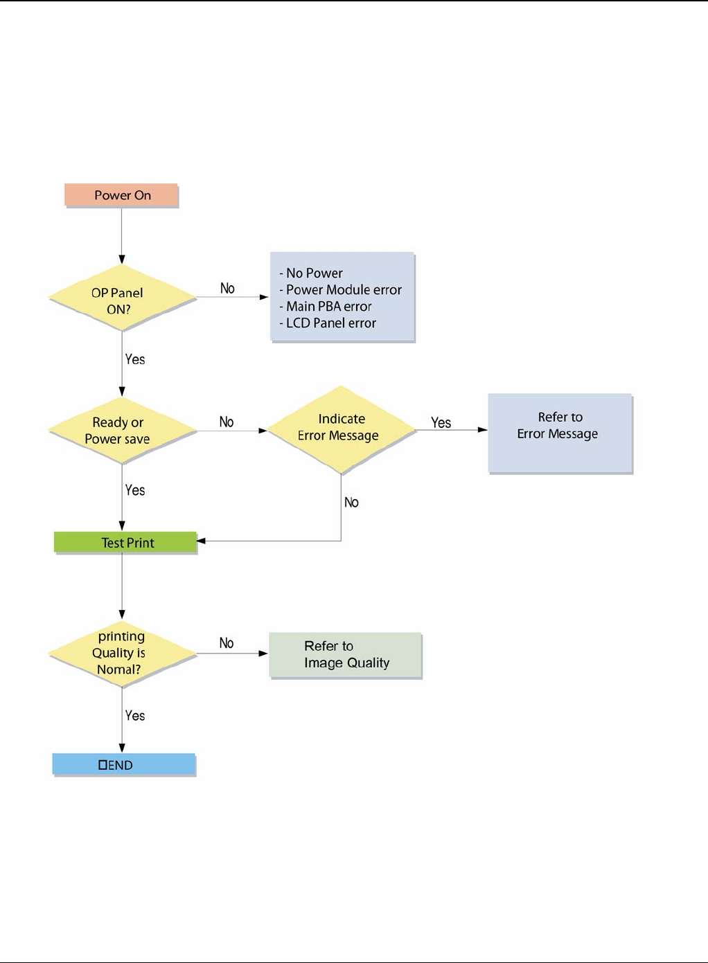
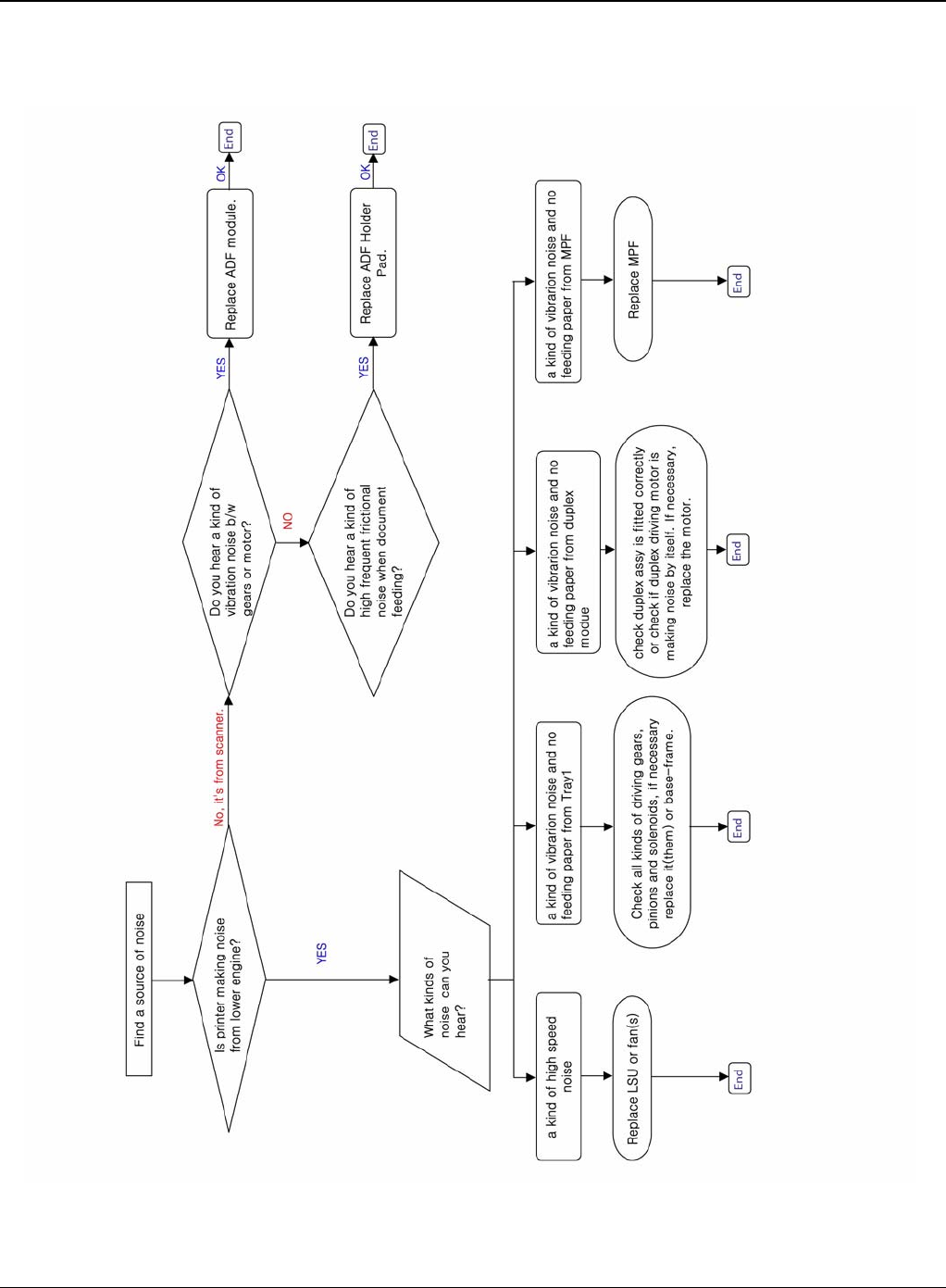
SCP 3 Troubleshooting
Procedure of Checking the Symptoms
Before attempting to repair the printer first obtain a detailed description of the problem from the
customer.
Figure 1

Service Call Procedures
1-6 5/08 Phaser 3435
SCP 4 Final Actions
After the machine has been re-assembled, perform the steps that follow:
1. Exercise the machine in all modes.
2. Make a proof copy or print of a customer document.
3. If any of the customers selections were changed, return them to the customers preferred set-
tings.
4. Mark off any hardware/software options and modifications installed and/or enabled in the
Service Log Book. Refer to GP 13.
5. At the first service and at any subsequent service where changes are made or options are
added, print the configuration report and store it with the machine log book. Discard any pre-
vious versions of the configuration report.
6. Remove and destroy any copies of test patterns.
7. Complete the machine service log book, refer to GP 13 Service Log.
8. Ensure the machine and service area are clean before leaving the customer premises.
9. Provide customer training if required.

Service Call Procedures
Phaser 3435 5/08 1-7
SCP 5 Consumables and Replacement Parts
To avoid print quality and paper feed problems resulting from worn parts and to maintain the print-
er in top working condition the following items will need to be replaced at the specified number of
pages or when the life span of each item has expired.
COMPONENT REPLACEMENT CYCLE
Pick-up Roller 150K Pages
Transfer Roller 70K Pages
Fuser 80K Pages
Print Cartridge 10K Pages (Sales), 4K Pages (Initial)

Service Call Procedures
1-8 5/08 Phaser 3435
This page is intentionally blank

Status Indicator RAPs
Phaser 3435 5/08 2-1
2 Status Indicator RAPs
RAP 1 LED Status Error ........................................................................................................... 2-3
RAP 2 Error Messages ............................................................................................................. 2-4
RAP 3 Nothing Displayed on LCD ............................................................................................ 2-6
RAP 4 Paper Jams ................................................................................................................... 2-7
RAP 5 JAM 0 .......................................................................................................................... 2-17
RAP 6 JAM 1 ......................................................................................................................... 2-19
RAP 7 JAM 2 .......................................................................................................................... 2-21
RAP 8 JAM Duplex 1 .............................................................................................................. 2-22
RAP 9 JAM Duplex 2 .............................................................................................................. 2-23
RAP 10 Multi-Feeding ............................................................................................................ 2-24
RAP 11 Paper Rolled in the Fuser ......................................................................................... 2-25
RAP 12 Paper Rolled on the OPC Drum ................................................................................ 2-26
RAP 13 Fuser Error ................................................................................................................ 2-27
RAP 14 LSU Error .................................................................................................................. 2-28
RAP 15 Fuser Drive Gear Damage ........................................................................................ 2-30
RAP 16 Paper Empty ............................................................................................................. 2-31
RAP 17 Paper Empty Without Indication ................................................................................ 2-32
RAP 18 Cover Open ............................................................................................................... 2-33
RAP 19 No Error Message When the Cover is Open ............................................................ 2-34
RAP 20 Defective Motor Operation ........................................................................................ 2-35
RAP 21 No Power .................................................................................................................. 2-36
RAP 22 Printer Not Working (1) ............................................................................................. 2-37
RAP 23 Printer Not Working (2) ............................................................................................. 2-38
RAP 24 Abnormal Printing .................................................................................................... 2-39
RAP 25 SPOOL Error ............................................................................................................. 2-40
RAP 26 Multi-Feed Error ........................................................................................................ 2-41
RAP 27 No Paper/Add Paper Error ........................................................................................ 2-42
RAP 28 Open Cover Error ...................................................................................................... 2-43
RAP 29 Fuser Door Open ...................................................................................................... 2-44
RAP 30 Audible Noise ............................................................................................................ 2-45
RAP 31 Scan Lock Error ........................................................................................................ 2-46

Status Indicator RAPs
2-2 5/08 Phaser 3435
This page is intentionally blank

Status Indicator RAPs
Phaser 3435 5/08 2-3
RAP 1 LED Status Error
Status Description
Off • The printer is off-line and cannot print.
• The printer is in power save mode. When data is received, it switches to on-
line automatically.
Green On The printer is on-line and can receive data from the computer.
Blinking • When the backlight blinks slowly, the printer is receiving data from the com-
puter.
• When the backlight blinks quickly, the printer is receiving and printing data.
Red On • The print cartridge is totally exhausted. Remove the old print cartridge and
install a new one.
• A paper jam has occurred. To solve the problem, go to RAP 4 Paper Jams.
• The front cover is open. Close the front cover.
• There is no paper in the tray. Load paper in the tray.
• The printer has stopped printing due to a major error. Check the display mes-
sage. for details on the meaning of the error message.
Blinking • A minor error is occurring and the printer is waiting for the error to be cleared.
Check the display message. When the problem is cleared, the printer resumes
printing.
• The print cartridge is low. Order a new print cartridge. You can temporarily
improve print quality by redistributing the toner.

Status Indicator RAPs
2-4 5/08 Phaser 3435
RAP 2 Error Messages
Message Meaning Suggested solutions
Door Open The front cover or rear cover is not
securely latched. Close the cover until it locks into place.
Duplex Jam 0 Check
Inside Paper has jammed during duplex
printing. Clear the jam.
Duplex Jam 1 Open/
Close Door Paper has jammed during duplex
printing. Clear the jam.
Fuser Door Open The fuser door is not securely
latched. Open the rear cover and close the fuser door
until it locks into place. For the location of the
fuser door.
Install Toner A print cartridge is not installed. Install a print cartridge.
Invalid Toner The print cartridge you have installed
is not for your printer. Install a genuine print cartridge, designed for
your printer.
Load Manual Press
Stop Key The multi-purpose tray is empty in
manual feed mode. Load a sheet of print material and press OK.
Low Heat Error Cycle
Power There is a problem in the fuser unit. Replace to Fuser Unit.
LSU Hsync Error Cycle
Power A problem has occurred in the LSU
(Laser Scanning Unit). Replace to LSU Unit.
LSU Motor Error Cycle
Power A problem has occurred in the LSU
(Laser Scanning Unit). Replace to LSU Unit.
Main Motor Locked There is a problem in the main motor. Open and then close the front cover.
Open Heat Error Cycle
Power There is a problem in the fuser unit. Unplug the power cord and plug it back in. If
the problem persists, please call for service.
Over Heat Error Cycle
Power There is a problem in the fuser unit. Unplug the power cord and plug it back in. If
the problem persists, please call for service.
Paper Jam 0 Open/
Close Door Paper has jammed in the feeding
area of the tray. Clear the jam.
Paper Jam 1 Open/
Close Door Paper has jammed in the fuser area. Clear the jam.
Paper Jam 2 Check
Inside Paper has jammed in the paper exit
area. Clear the jam.
Printing... The printer is printing jobs using the
displayed language. Complete your printing.
Ready The printer is on-line and ready to
printer. Use your printer.
Replace Toner This message appears between the
Toner Empty and Toner Low status. Replace the print cartridge with a new one.

Status Indicator RAPs
Phaser 3435 5/08 2-5
Self Diagnostic... The engine in your printer is checking
some problems detected. Please wait a few minutes.
Sleeping... The printer is on power save mode. When data is received, it switches to on-line
automatically.
Toner Empty The print cartridge has run out. The
printer stops printing. Replace the print cartridge with a new one.
Toner Low The print cartridge is almost empty. Take out the print cartridge and thoroughly
shake it. By doing this, you can temporarily
reestablish printing operations.
Tray 1 Paper Empty There is no paper in the tray 1. Load paper in the tray 1.
Tray 2 Paper Empty There is no paper in the optional tray
2. Load paper in the optional tray 2.
Status Indicator RAPs
2-6 5/08 Phaser 3435
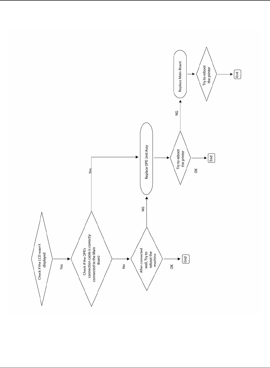
RAP 3 Nothing Displayed on LCD
Figure 1
Status Indicator RAPs
Phaser 3435 5/08 2-7
RAP 4 Paper Jams
Clearing Paper Jams
Jams in the Paper Feed Area
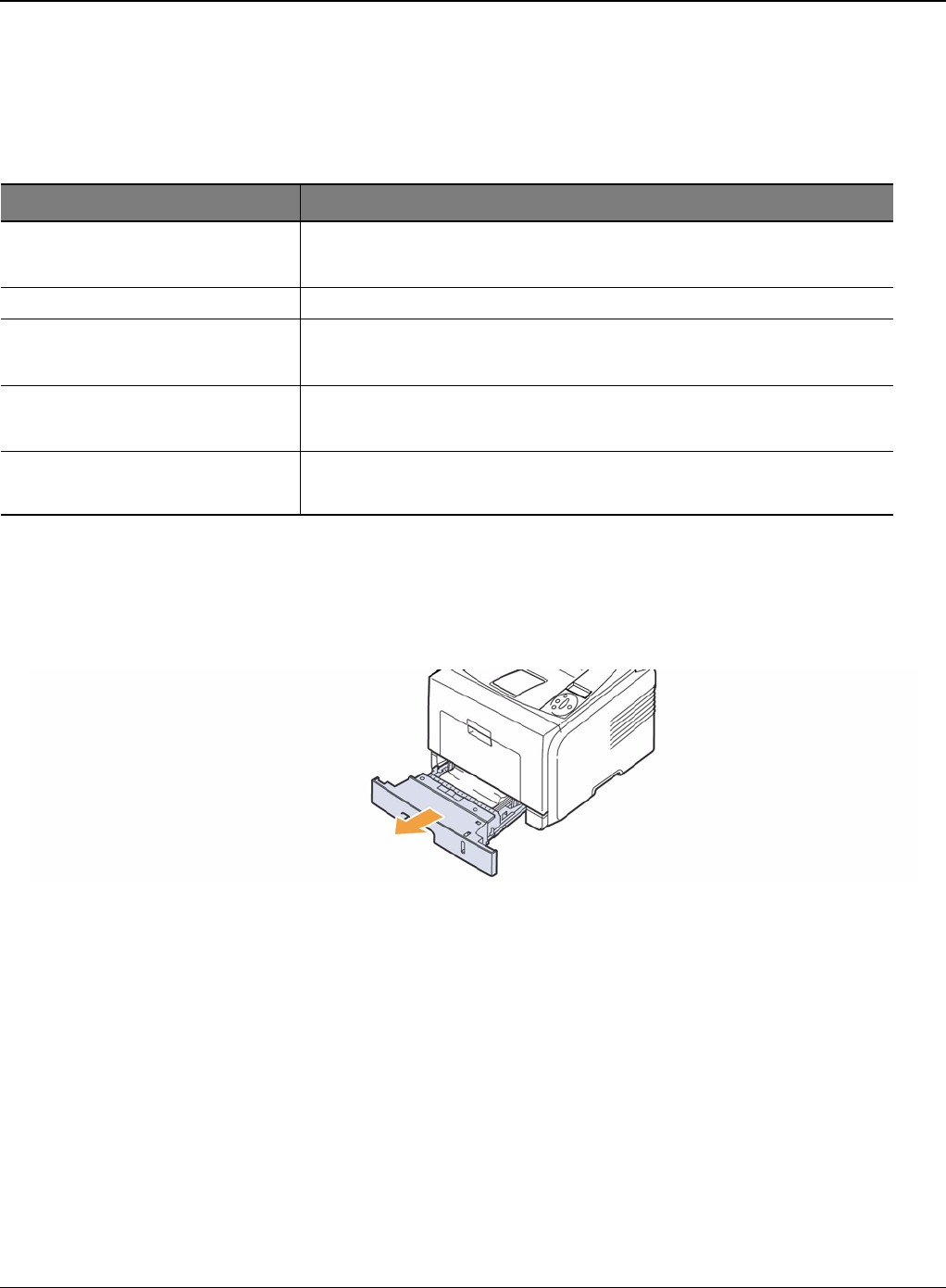
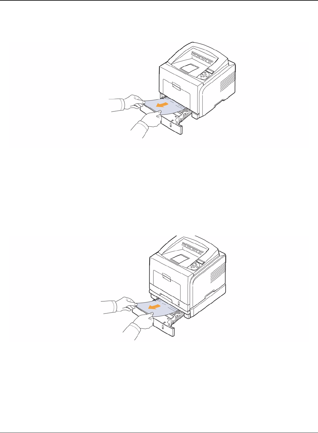
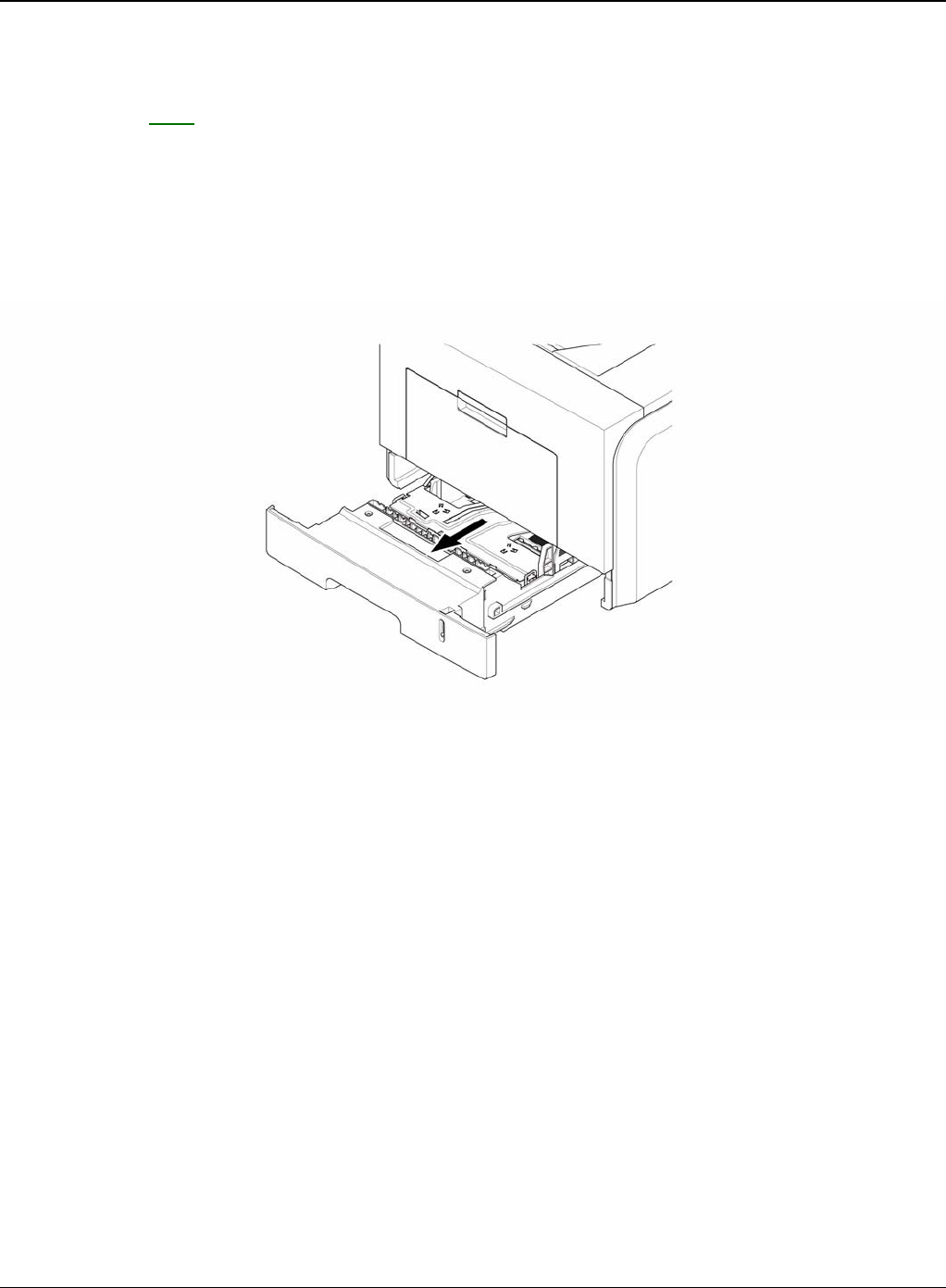
In the Tray
1. Pull the tray 1
Figure 1
Message Location of Jam
Paper Jam 0 Open/Close Door In the paper feed area (tray 1, optional tray 2, multi-purpose tray)
Paper Jam 1 Around the print cartridge
Open/Close Door Paper Jam 2 Check Inside In the paper exit area
Duplex Jam 0 Check Inside In the duplex area
Duplex Jam 1 Open/Close Door Between the duplex unit and fuser area
Status Indicator RAPs
2-8 5/08 Phaser 3435
2. Remove the jammed paper by gently pulling it straight out. Make sure that all of the paper is
properly aligned in the tray 1.
Figure 2
If the paper is not move when you pull, or if you do not see the paper in this area, check the
fuser area around the print cartridge.
3. Insert the tray 1 into the printer until it snaps into place. Printing automatically resumes.
In the Optional Tray 2
1. Pull the optional tray 2 open.
2. Remove the jammed paper from the printer.
Figure 3
If the paper is not move when you pull, or if you do not see the paper in this area, stop and go
to step 3.
3. Pull the tray 1 half.
4. Pull the paper straight up and out.
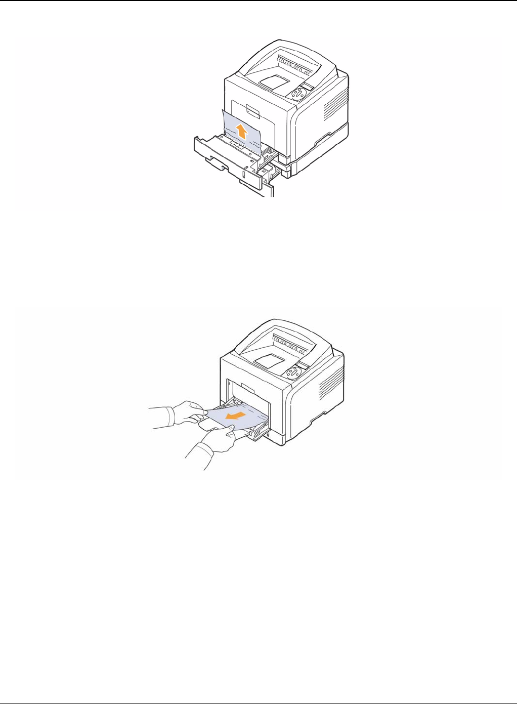
Status Indicator RAPs
Phaser 3435 5/08 2-9
Figure 4
5. Insert the trays back into the printer. Printing automatically resumes.
In the Multi-Purpose Tray
1. If the paper is not feeding properly, pull the paper out of the printer.
Figure 5
2. Open and close the front cover to resume printing.
Around the Print Cartridge
1. Open the front cover and pull the print cartridge out.
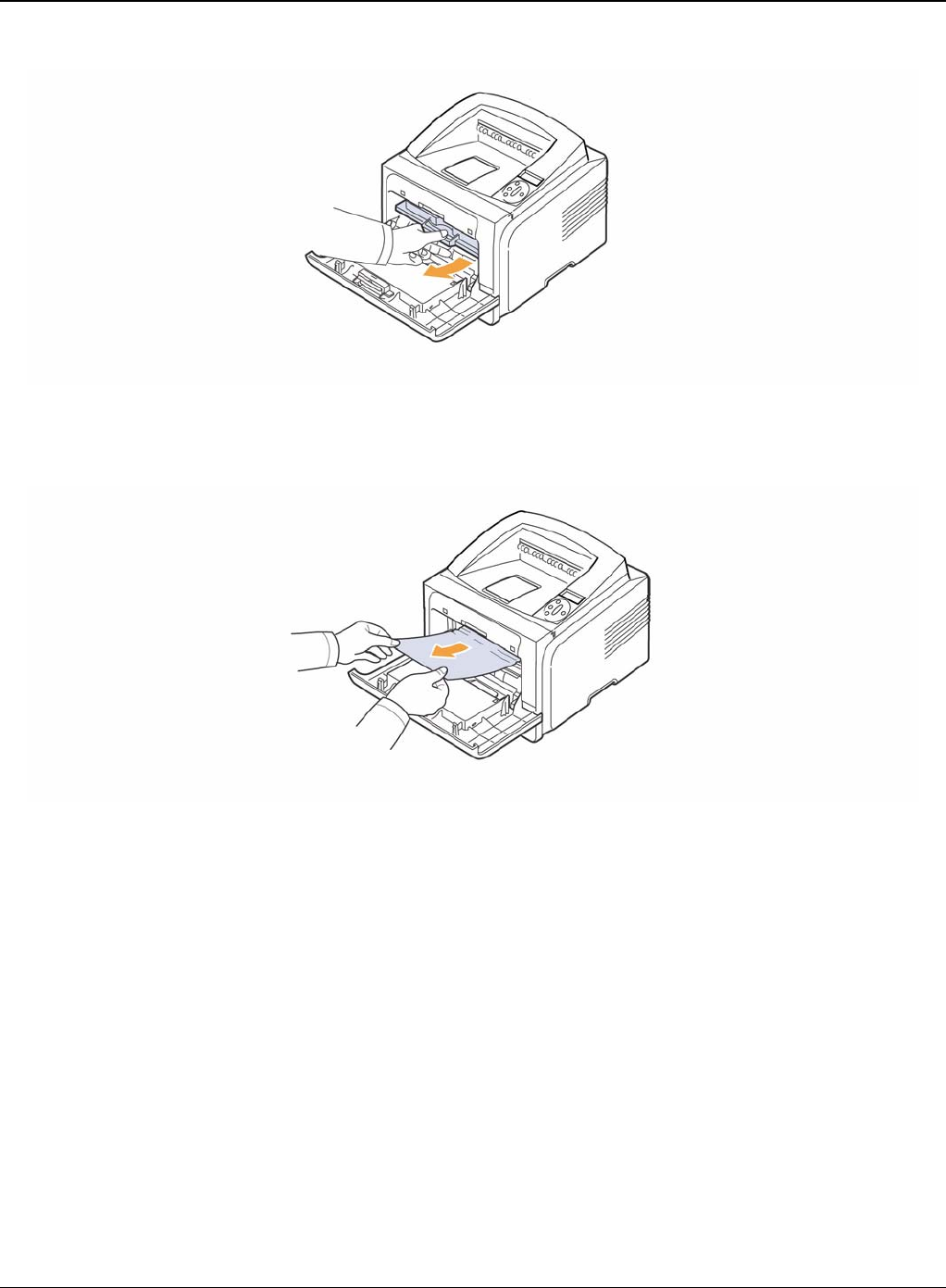
Status Indicator RAPs
2-10 5/08 Phaser 3435
Figure 1
2. Remove the jammed paper by gently pulling it straight out.
Figure 2
3. Replace the print cartridge and close the front cover. Printing automatically resumes.
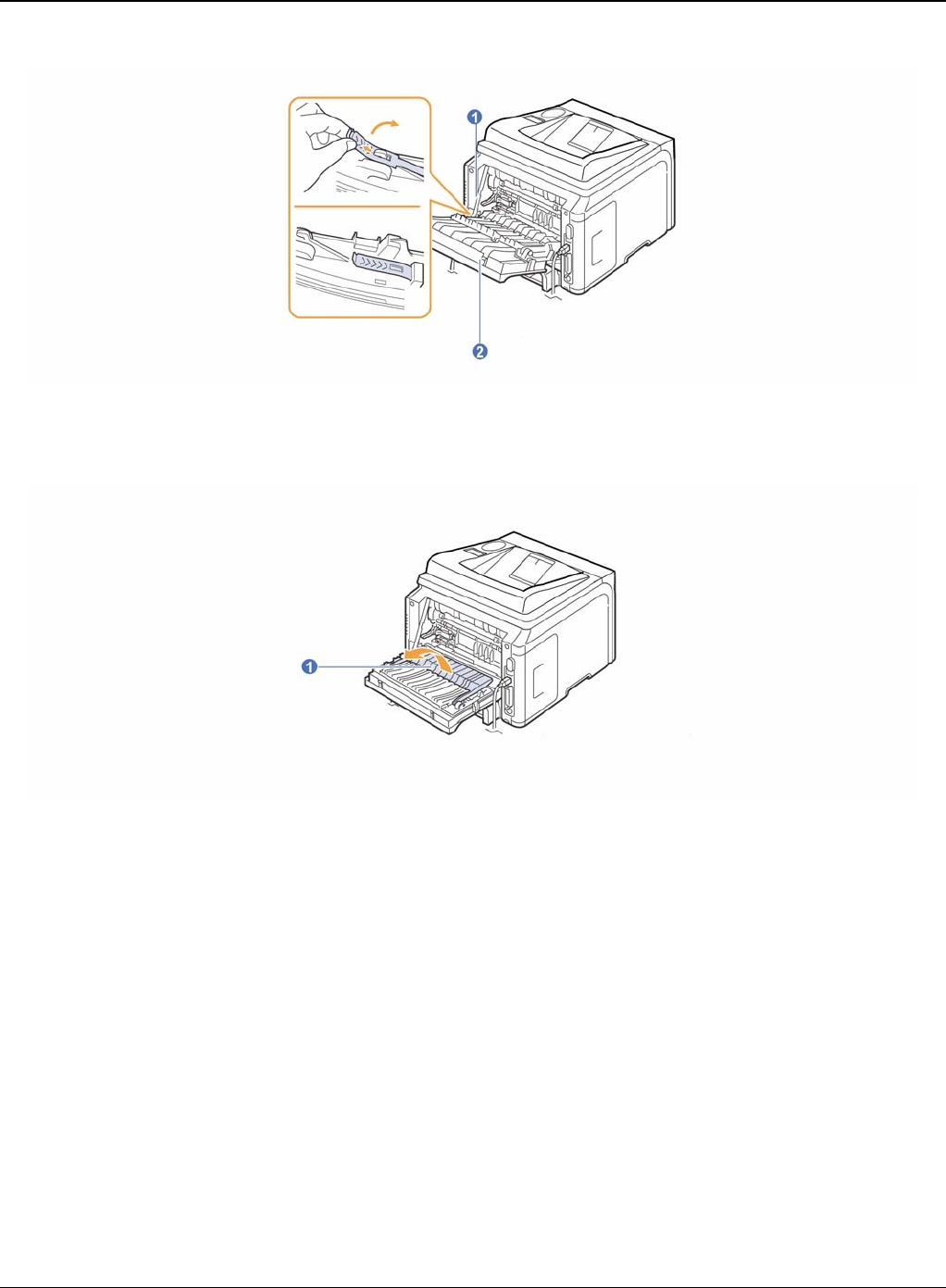
In the Paper Exit Area
1. Open and close the front cover. The jammed paper is automatically ejected from the printer.
2. Gently pull the paper out of the output tray.
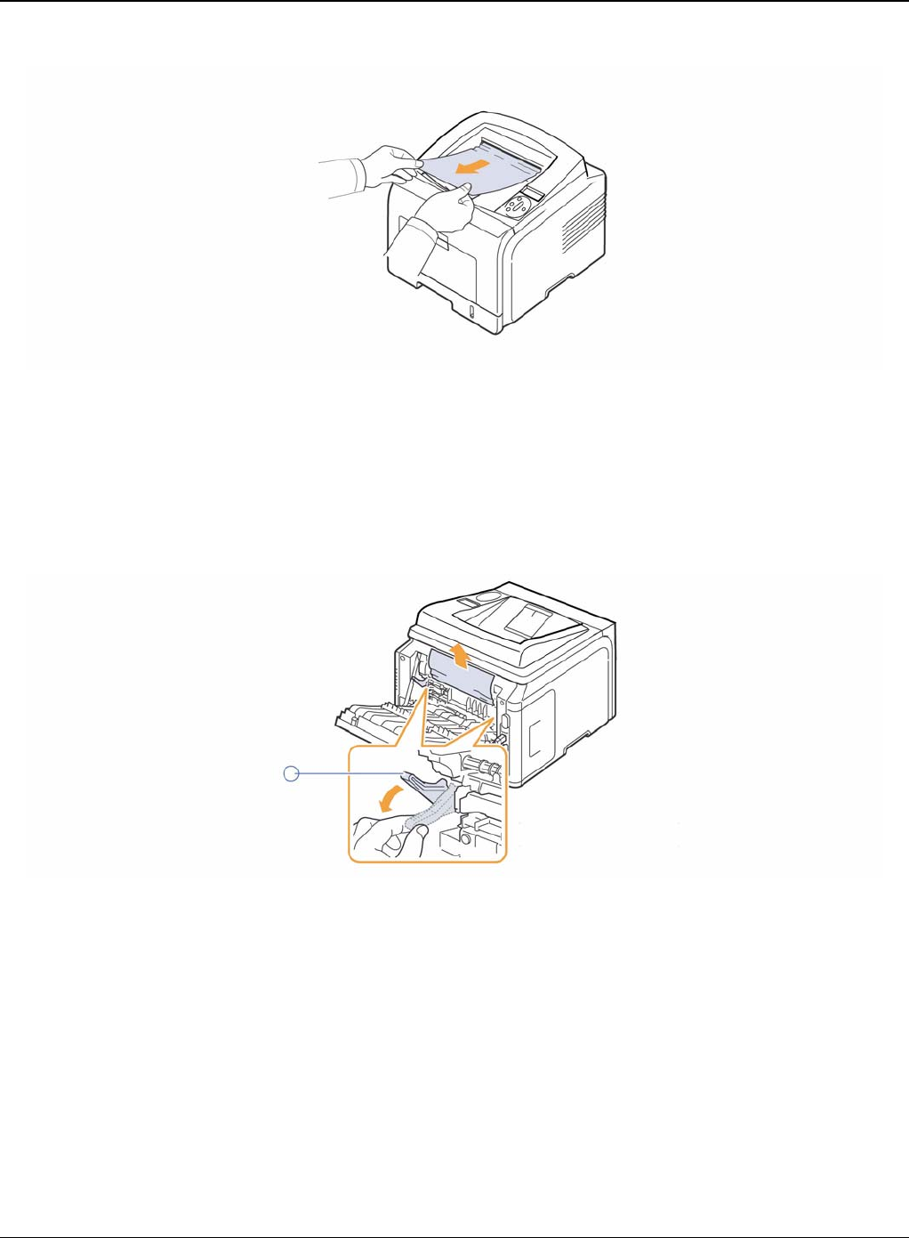
Status Indicator RAPs
Phaser 3435 5/08 2-11
Figure 1
If you do not see the jammed paper or if there is any resistance when you pull, stop and go to
the next step.
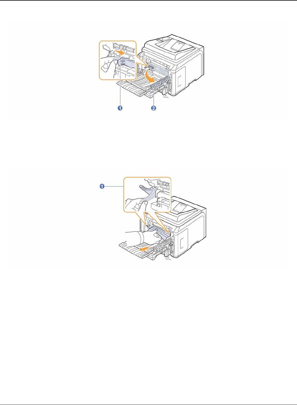
3. Open the rear cover.
4. If you see the jammed paper, push the pressure lever on each side up and remove the paper.
Return the pressure lever to its original position.
Figure 2
If you still do not see the paper, go to the next step.
5. Release the blue strap, the rear cover stopper, and fully open the rear cover, as shown.
Status Indicator RAPs
2-12 5/08 Phaser 3435
Figure 3
6. Unfold the duplex guide fully.
Figure 4
7. While pushing the fuser lever to the right, open the fuser door.
Status Indicator RAPs
Phaser 3435 5/08 2-13
Figure 5
8. Pull the jammed paper out.
If the jammed paper does not move when you pull, push the pressure lever on each side up
to loose the paper, and then remove it.
Figure 6
1
9. Return the lever, door, stopper, and guide to their original position.
10.Close the rear cover. Printing automatically resumes.
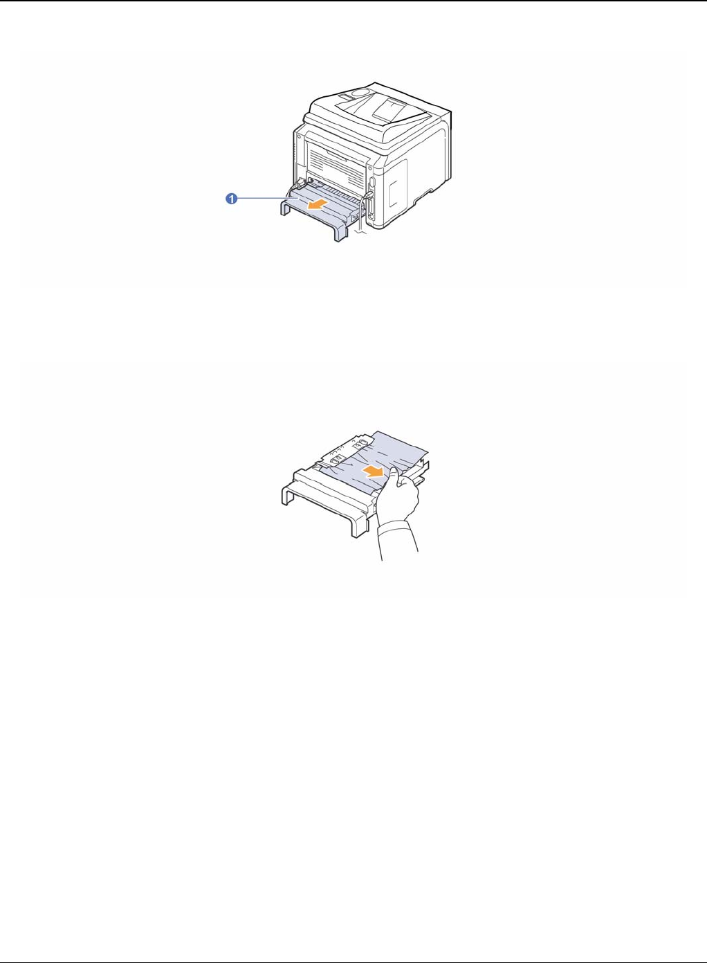
In the Duplex Unit Area
If the duplex unit is not inserted correctly, paper jam may occur. Make sure that the duplex unit is
inserted correctly.
Duplex jam 0
1. Pull the duplex unit out of the printer.
Status Indicator RAPs
2-14 5/08 Phaser 3435
Figure 1
2. Remove the jammed paper from the duplex unit.
Figure 2
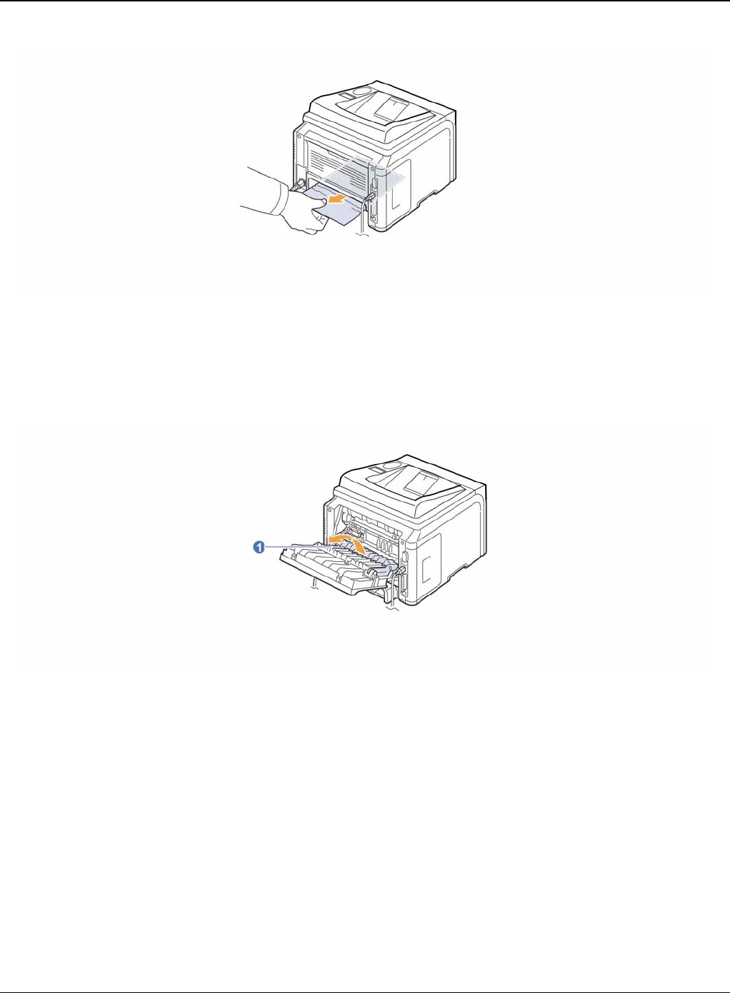
If the paper does not come out with the duplex unit, remove the paper from the bottom of the print-
er.
Status Indicator RAPs
Phaser 3435 5/08 2-15
Figure 3
Duplex jam 1
1. Open the rear cover.
2. Unfold the duplex guide fully.
Figure 4

Status Indicator RAPs
2-16 5/08 Phaser 3435
3. Pull the jammed paper out.
Figure 5
Status Indicator RAPs
Phaser 3435 5/08 2-17
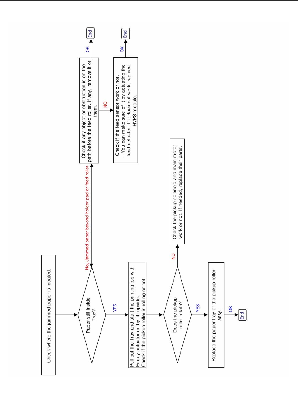
RAP 5 JAM 0
1. Paper is not exited from the cassette.
2. Jam-0 occurs when the paper feeds into the printer.
Figure 1
Status Indicator RAPs
2-18 5/08 Phaser 3435
Figure 2
Status Indicator RAPs
Phaser 3435 5/08 2-19
RAP 6 JAM 1
Description
1. Paper is jammed in front of or inside the fuser.
2. Paper is stuck in the discharge roller and in the fuser just after passing through the feed sen-
sor actuator.
Figure 1
Status Indicator RAPs
2-20 5/08 Phaser 3435
Figure 2
Status Indicator RAPs
Phaser 3435 5/08 2-21
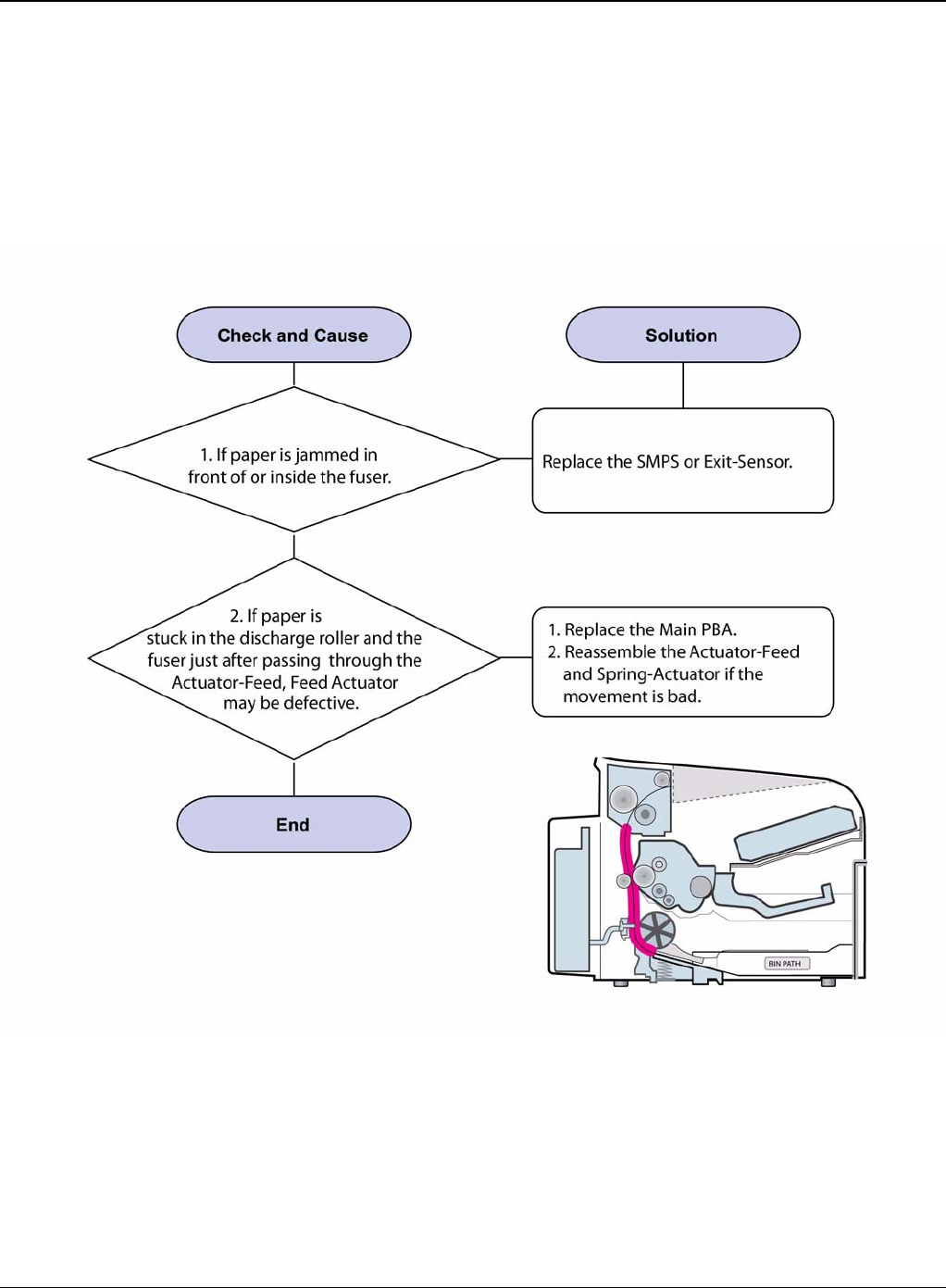
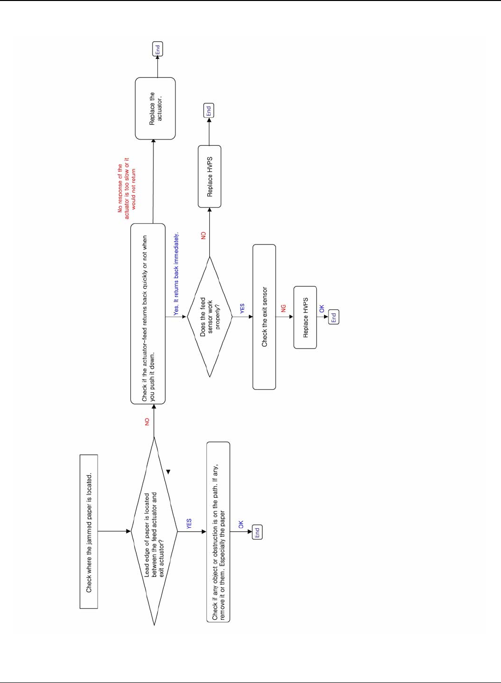
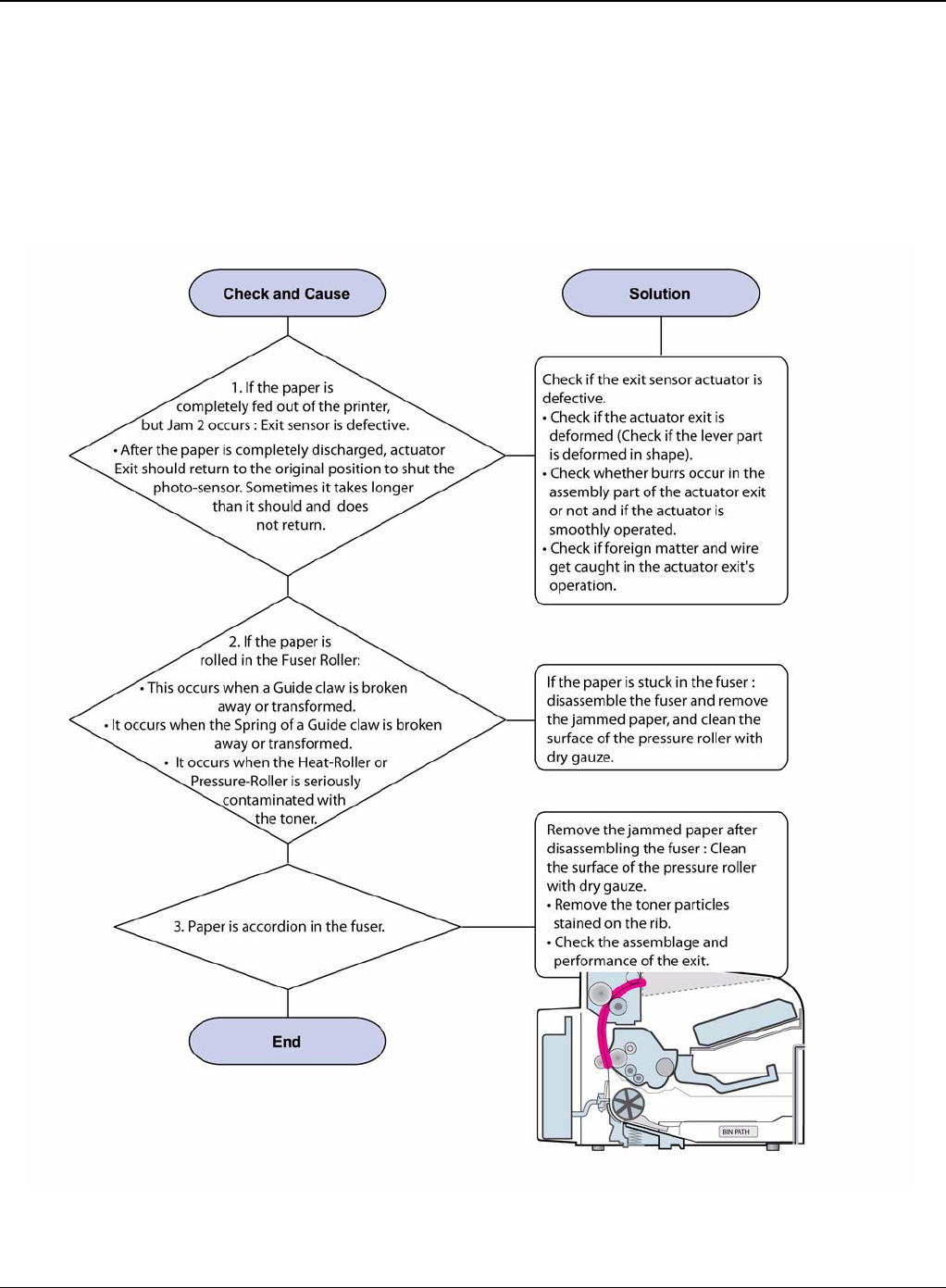
RAP 7 JAM 2
Description
1. Paper is jammed in front of or inside the fuser.
2. Paper is stuck in the discharge roller and in the fuser just after passing through the Actuator-
Feed.
Figure 1
Status Indicator RAPs
2-22 5/08 Phaser 3435
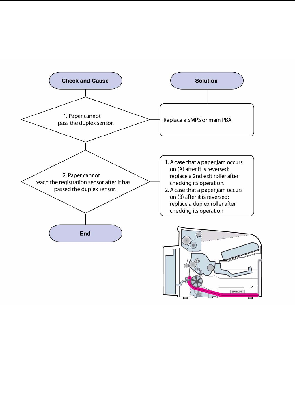
RAP 8 JAM Duplex 1
Description
A message “Jam Duplex 1” is displayed in a LCD window.
Figure 1
Status Indicator RAPs
Phaser 3435 5/08 2-23
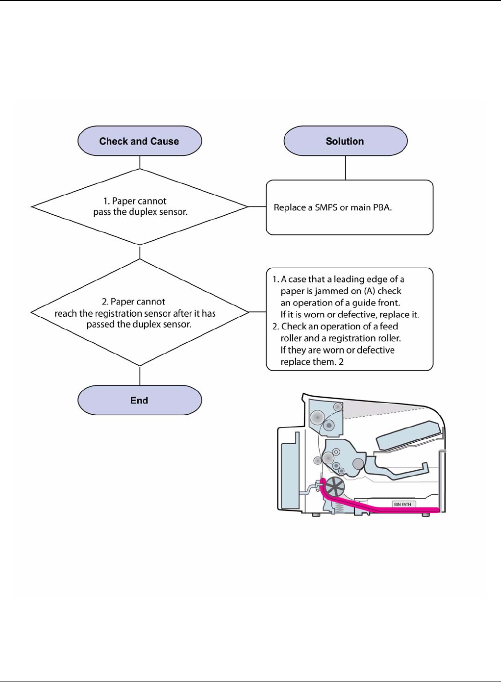
RAP 9 JAM Duplex 2
Description
A message “Jam Duplex 2” is displayed in a LCD window.
Figure 1
Status Indicator RAPs
2-24 5/08 Phaser 3435
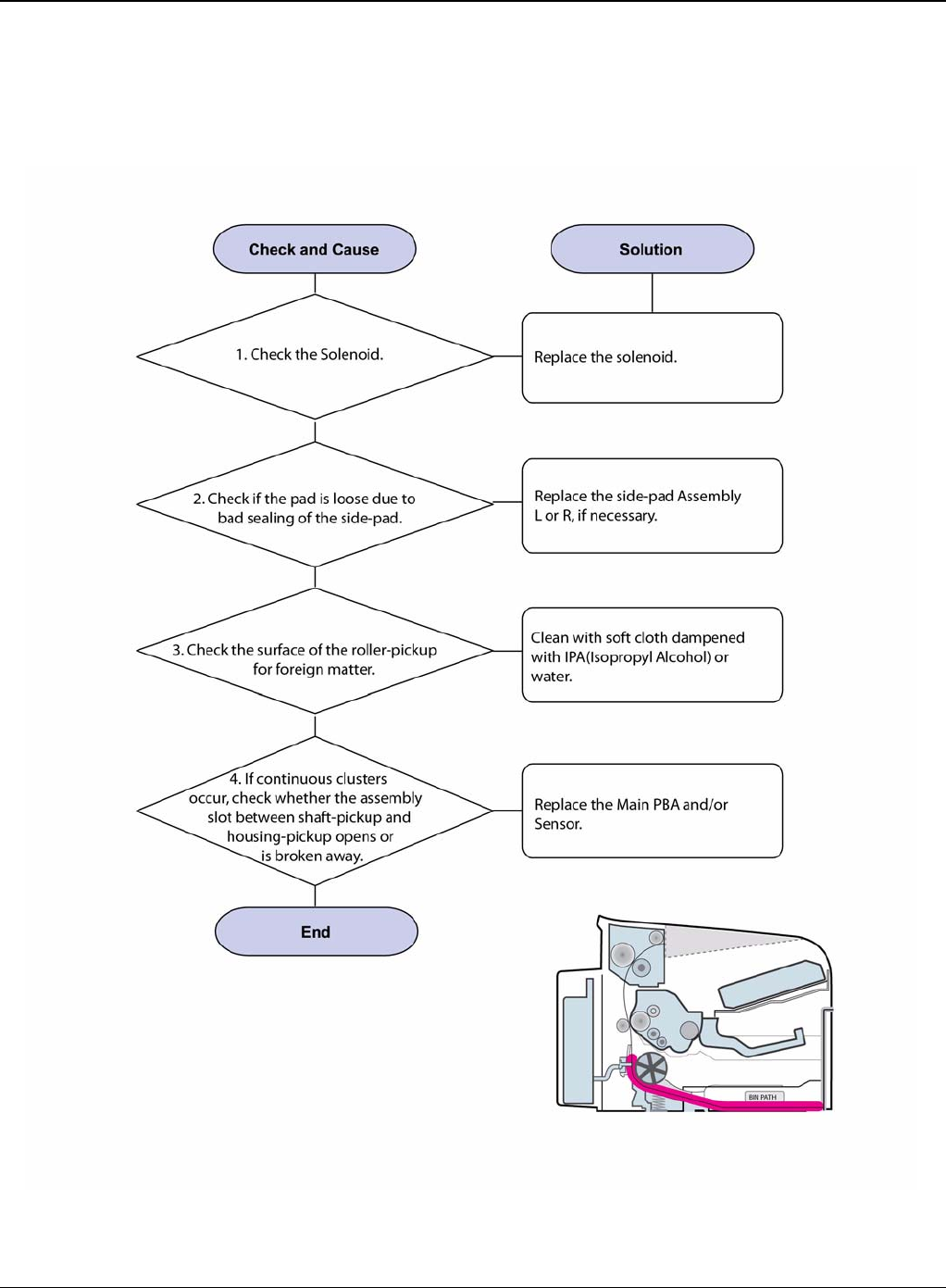
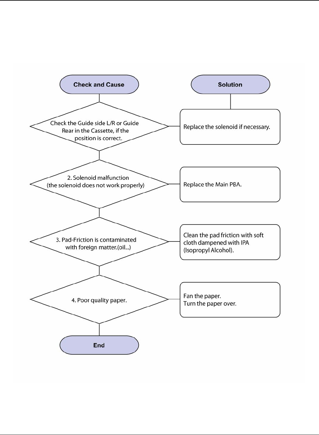
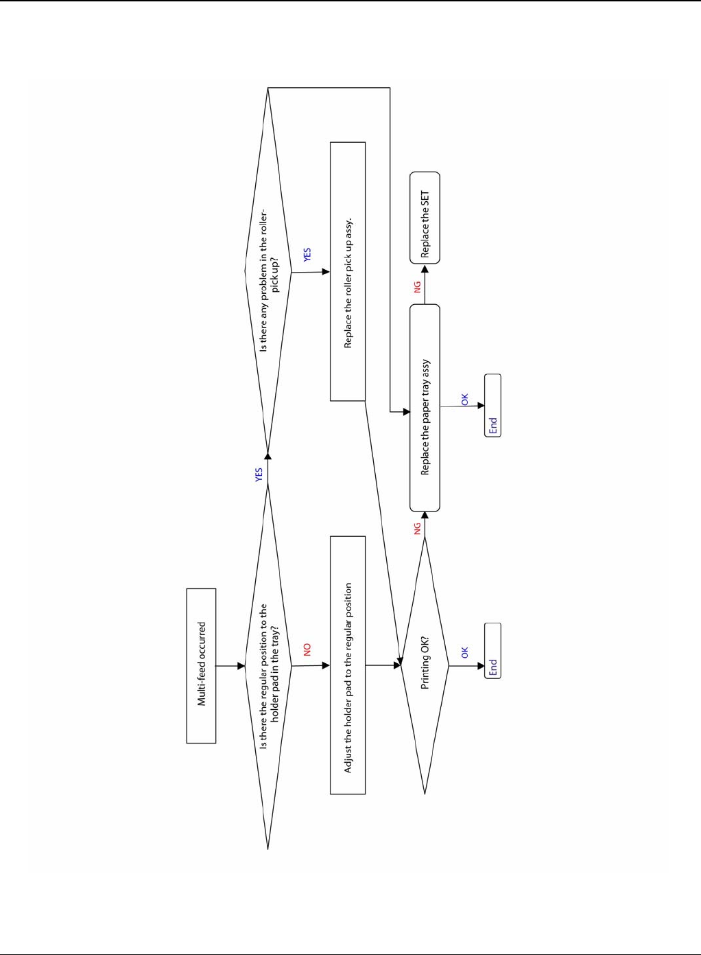
RAP 10 Multi-Feeding
Description
Multiple sheets of paper are fed at once.
Figure 1
Status Indicator RAPs
Phaser 3435 5/08 2-25
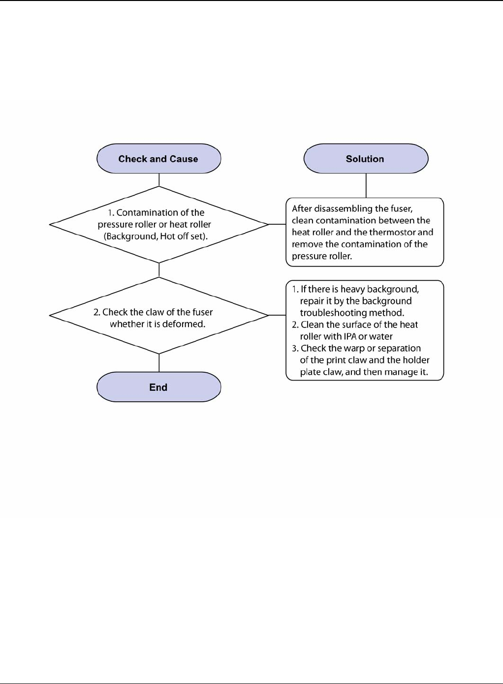
RAP 11 Paper Rolled in the Fuser
Description
Paper is jammed in the fuser.
Figure 1
Status Indicator RAPs
2-26 5/08 Phaser 3435
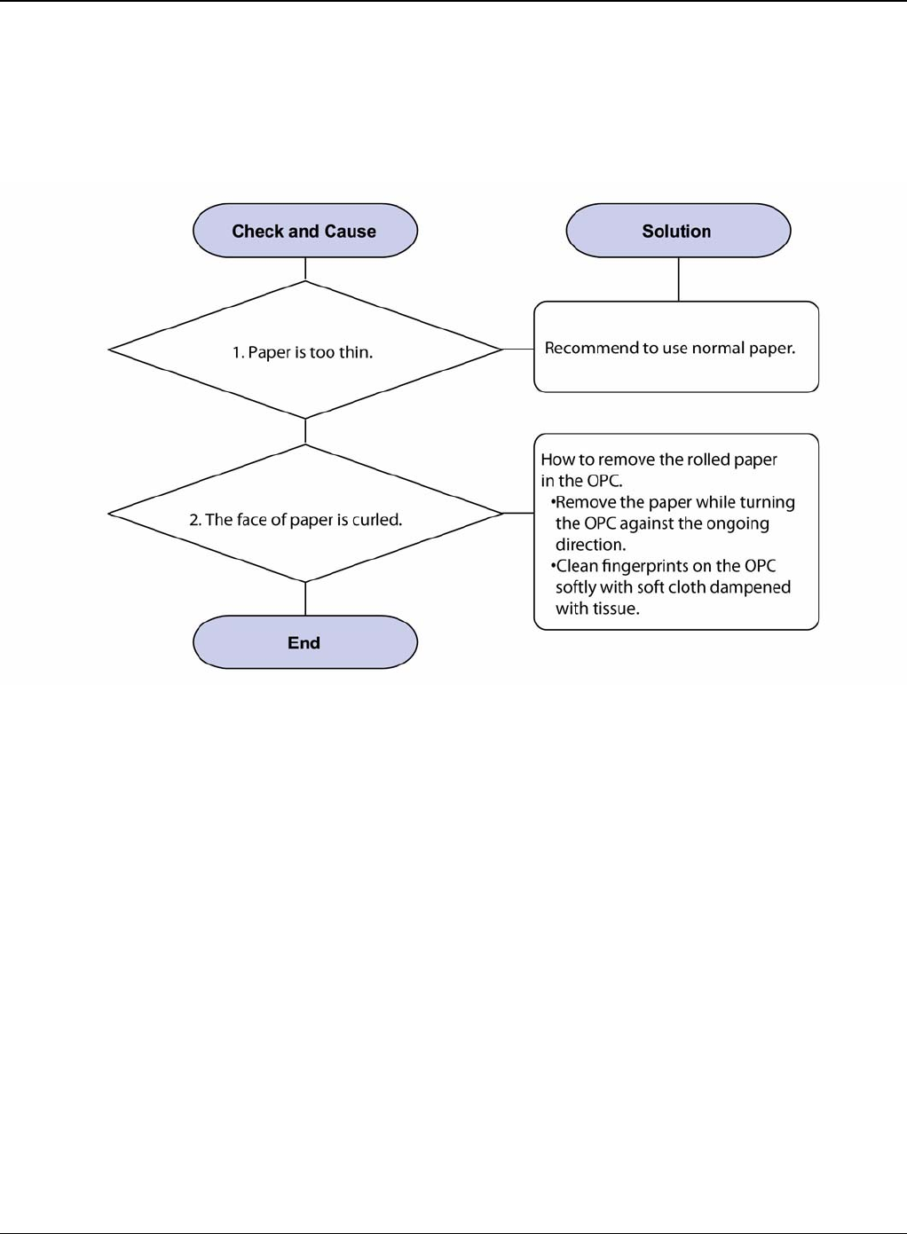
RAP 12 Paper Rolled on the OPC Drum
Description
Paper is rolled up in the OPC.
Figure 1
Status Indicator RAPs
Phaser 3435 5/08 2-27
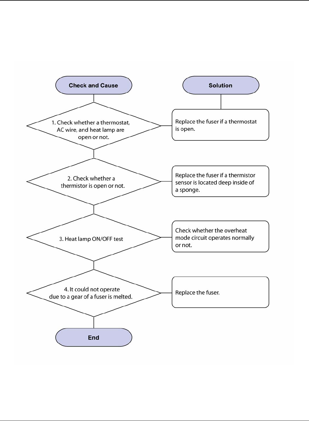
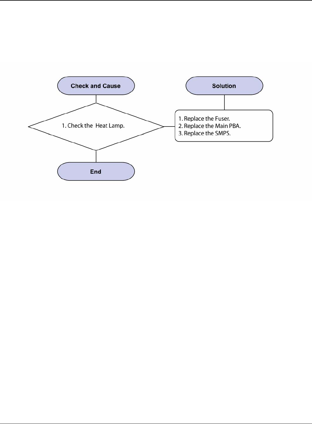
RAP 13 Fuser Error
Description
A message “Open fuser/Over heat/Low heat” is displace in a LCD panel.
Figure 1
Status Indicator RAPs
2-28 5/08 Phaser 3435
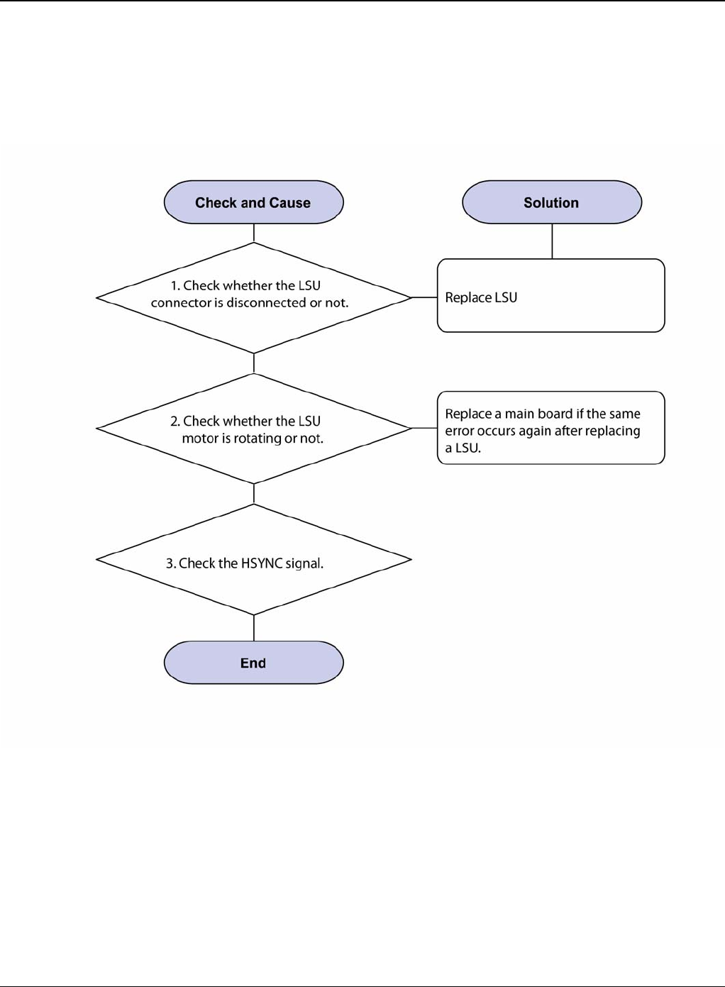
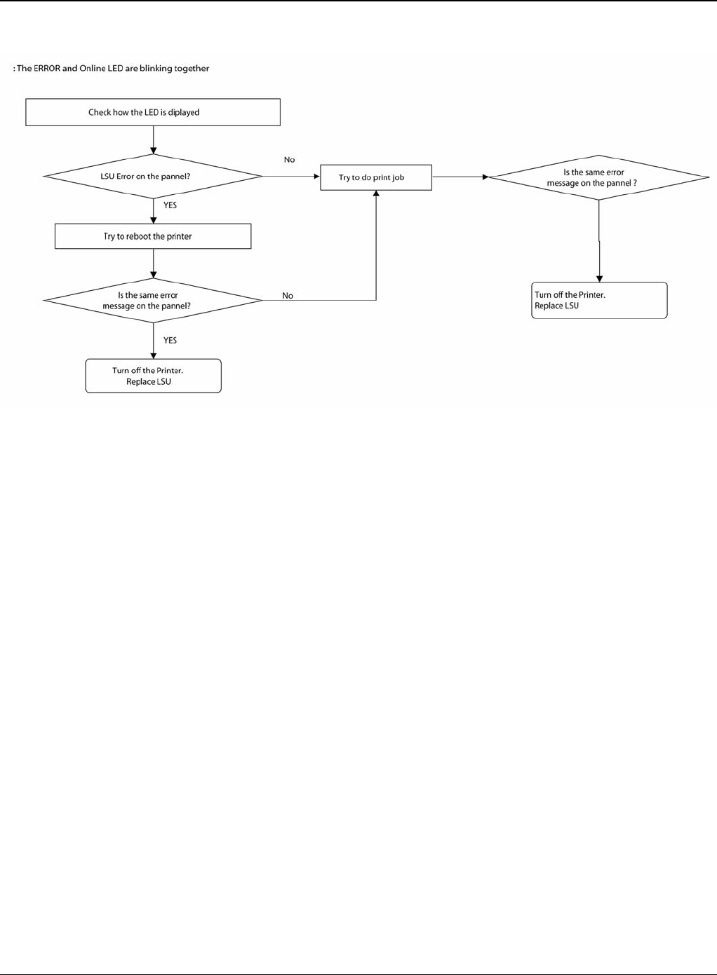
RAP 14 LSU Error
Description
A message “PMOTOR ERROR/HSYNC ERROR” is displayed in a LCD panel.
Figure 1
Status Indicator RAPs
Phaser 3435 5/08 2-29
Figure 2
Status Indicator RAPs
2-30 5/08 Phaser 3435
RAP 15 Fuser Drive Gear Damage
Description
The motor breaks away from its place due to gear melting away.
Figure 1
Status Indicator RAPs
Phaser 3435 5/08 2-31
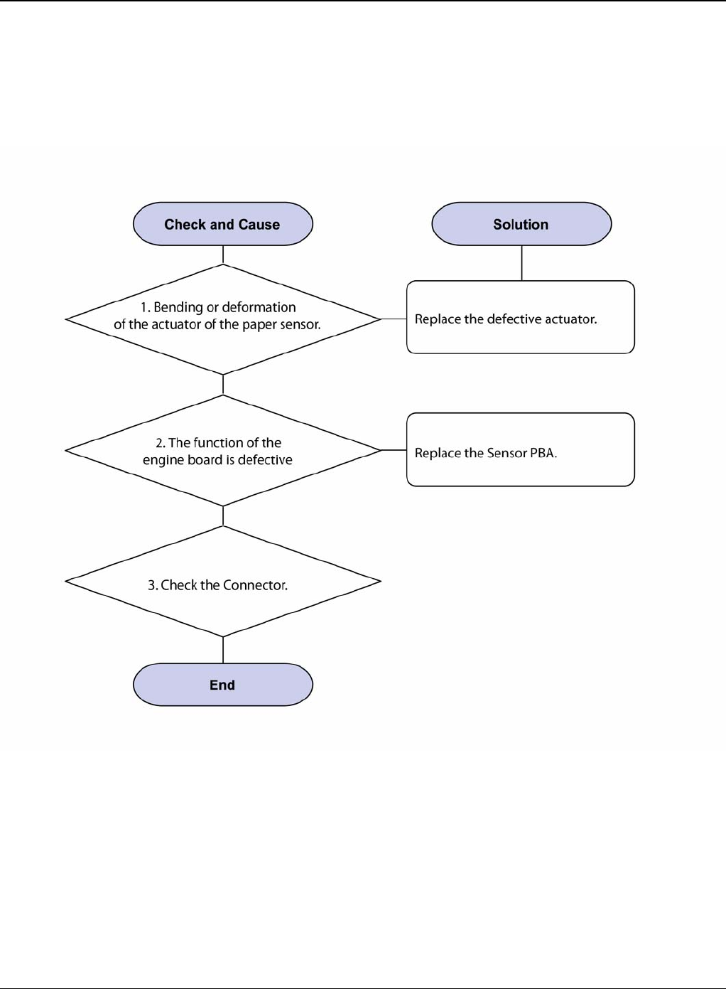
RAP 16 Paper Empty
Description
The paper lamp on the operator panel is on even when paper is loaded in the cassette.
Figure 1
Status Indicator RAPs
2-32 5/08 Phaser 3435
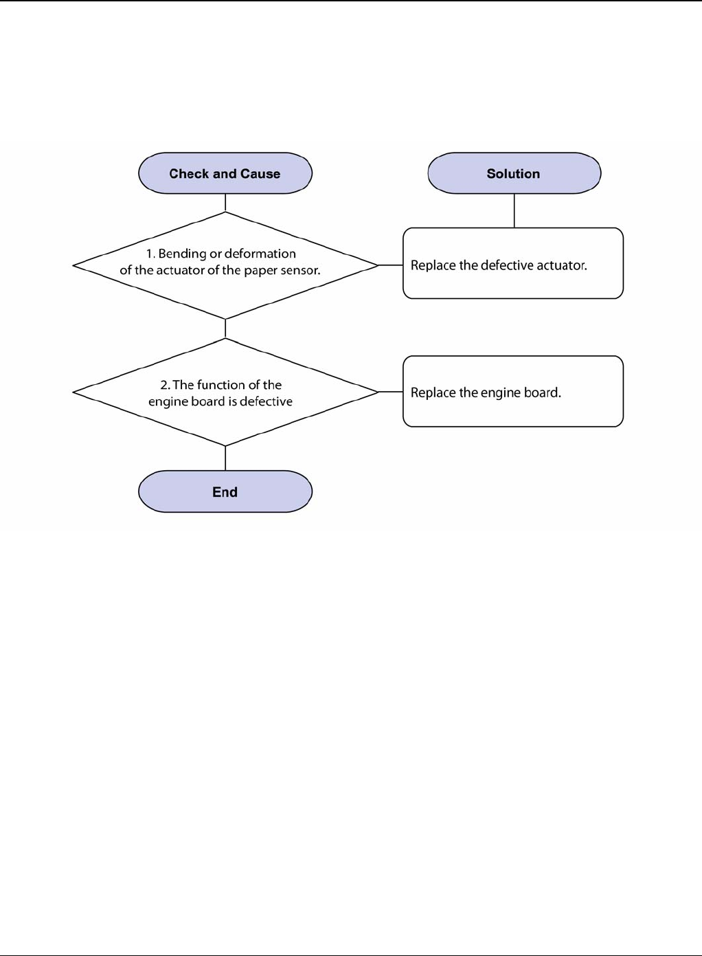
RAP 17 Paper Empty Without Indication
Description
The paper lamp on the operator panel does not come on when the paper cassette is empty.
Figure 1
Status Indicator RAPs
Phaser 3435 5/08 2-33
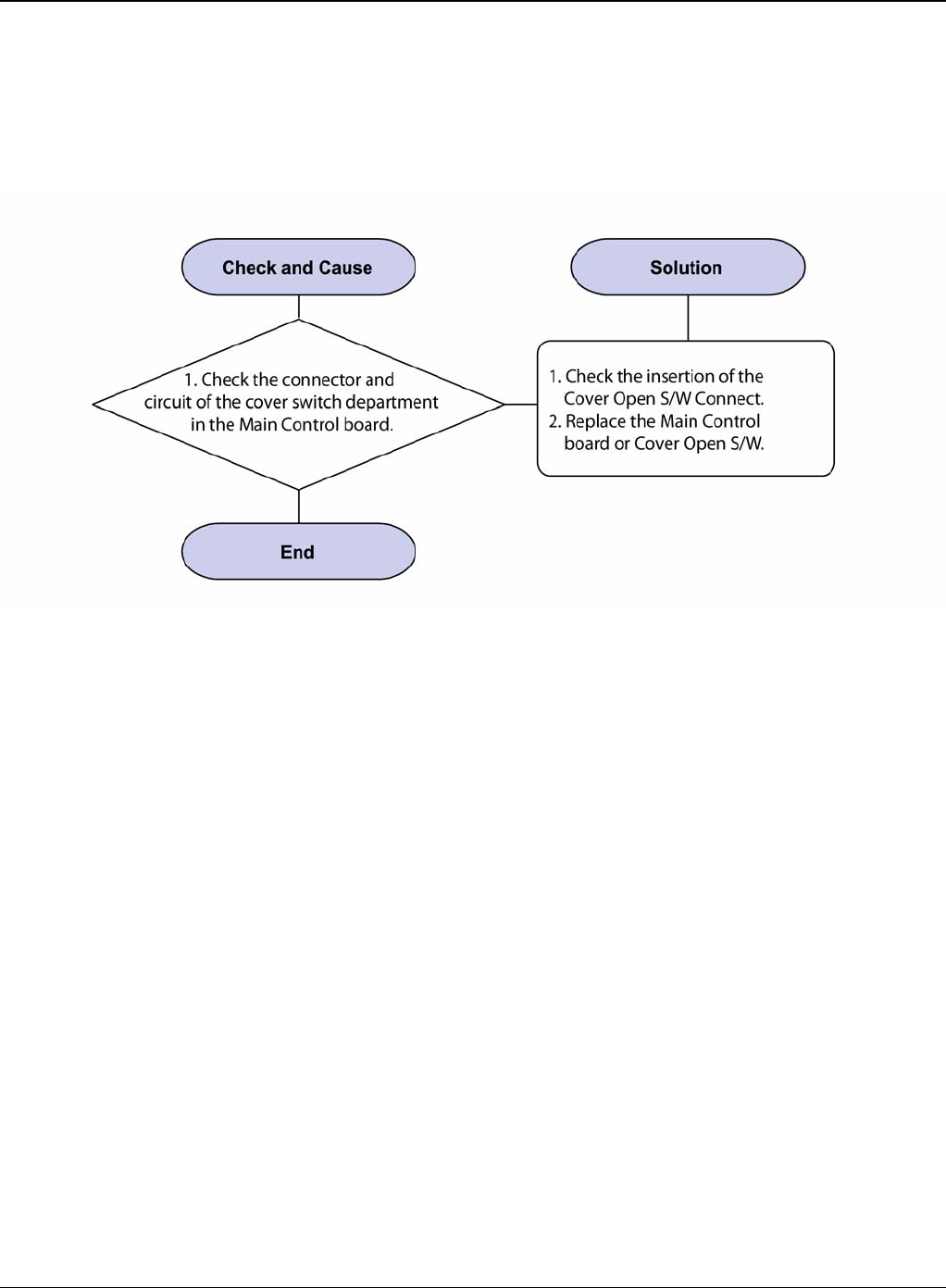
RAP 18 Cover Open
Description
The ERROR lamp is on even when the print cover is closed.
Figure 1
Status Indicator RAPs
2-34 5/08 Phaser 3435
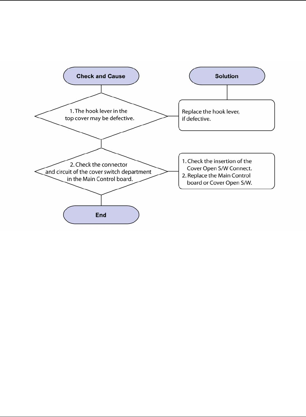
RAP 19 No Error Message When the Cover is Open
Description
The ERROR message does not come on even when the printer cover is open.
Figure 1
Status Indicator RAPs
Phaser 3435 5/08 2-35
RAP 20 Defective Motor Operation
Description
Main motor is not driving when printing and paper does not feed into the printer.
Figure 1
Status Indicator RAPs
2-36 5/08 Phaser 3435
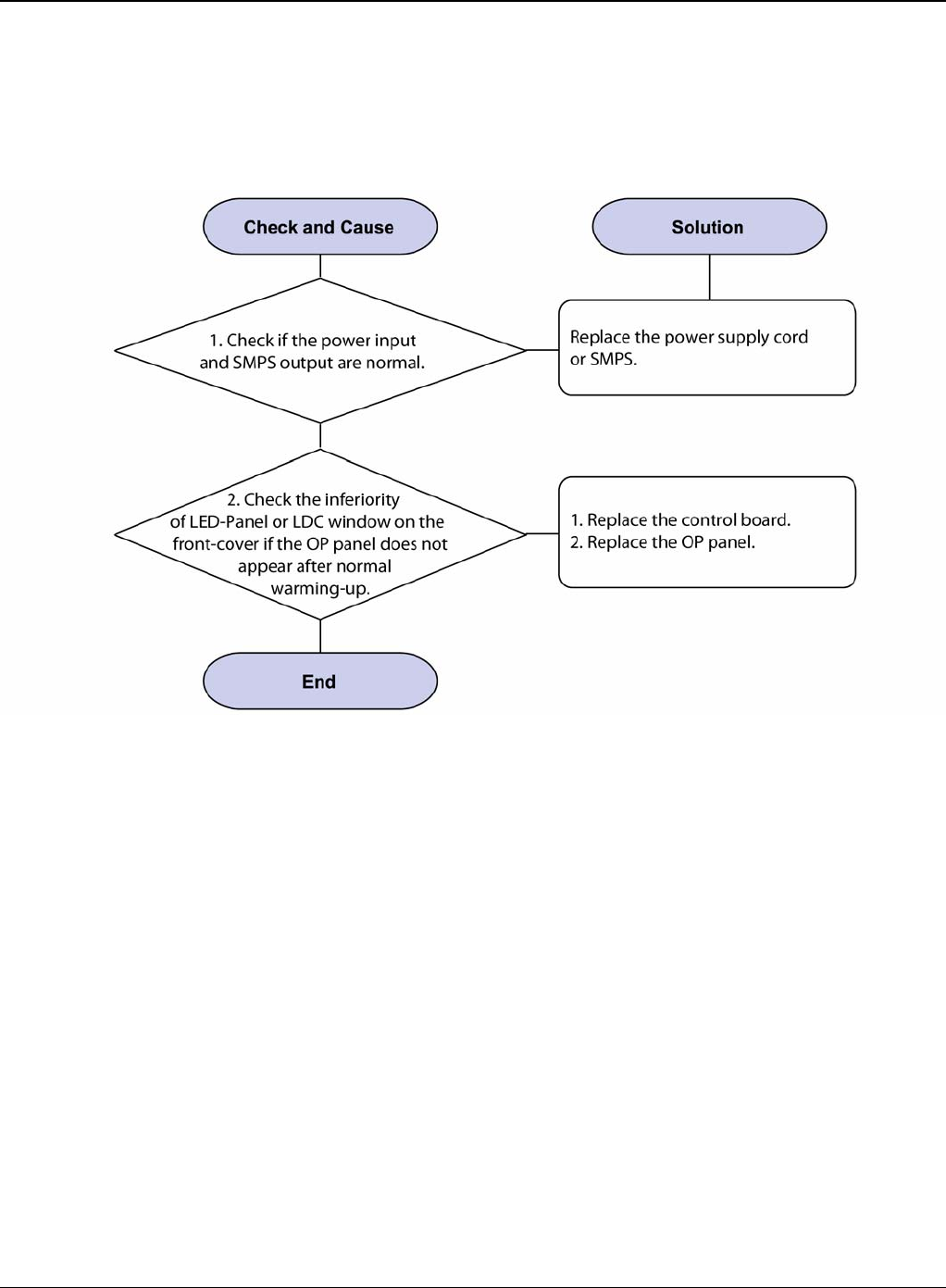
RAP 21 No Power
Description
When system power is turned on, all lamps on the operator panel do not come on.
Figure 1
Status Indicator RAPs
Phaser 3435 5/08 2-37
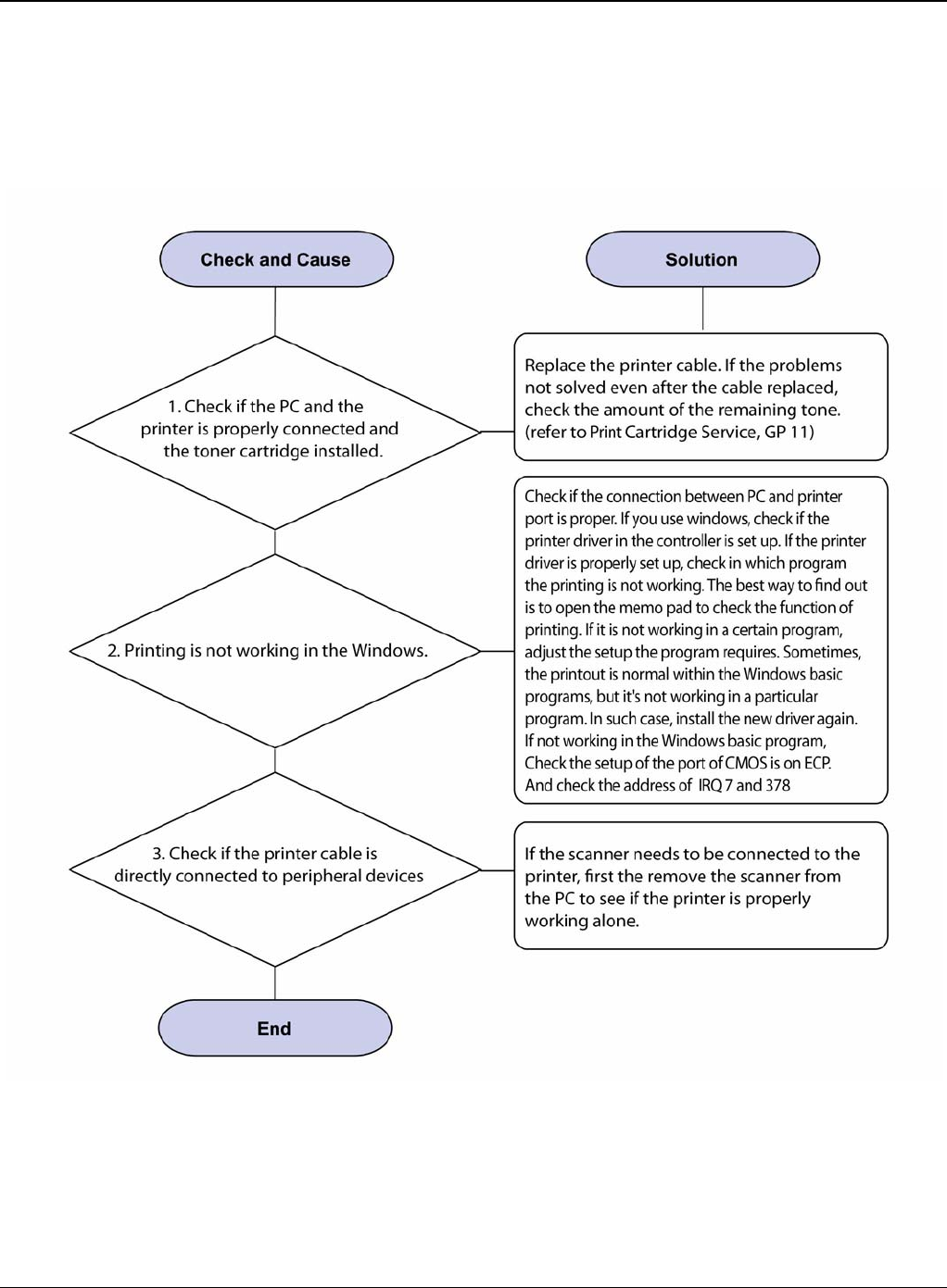
RAP 22 Printer Not Working (1)
Description
While Power turned on, the printer is not working in the printing mode.
Figure 1
Status Indicator RAPs
2-38 5/08 Phaser 3435
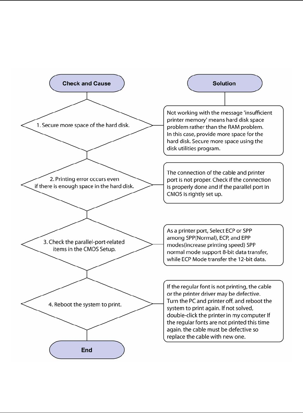
RAP 23 Printer Not Working (2)
Description
After receiving the printing order, no response at all or the low speed of printing occurs due to
wrong setup of the environment rather than malfunction of the printer itself.
Figure 1
Status Indicator RAPs
Phaser 3435 5/08 2-39
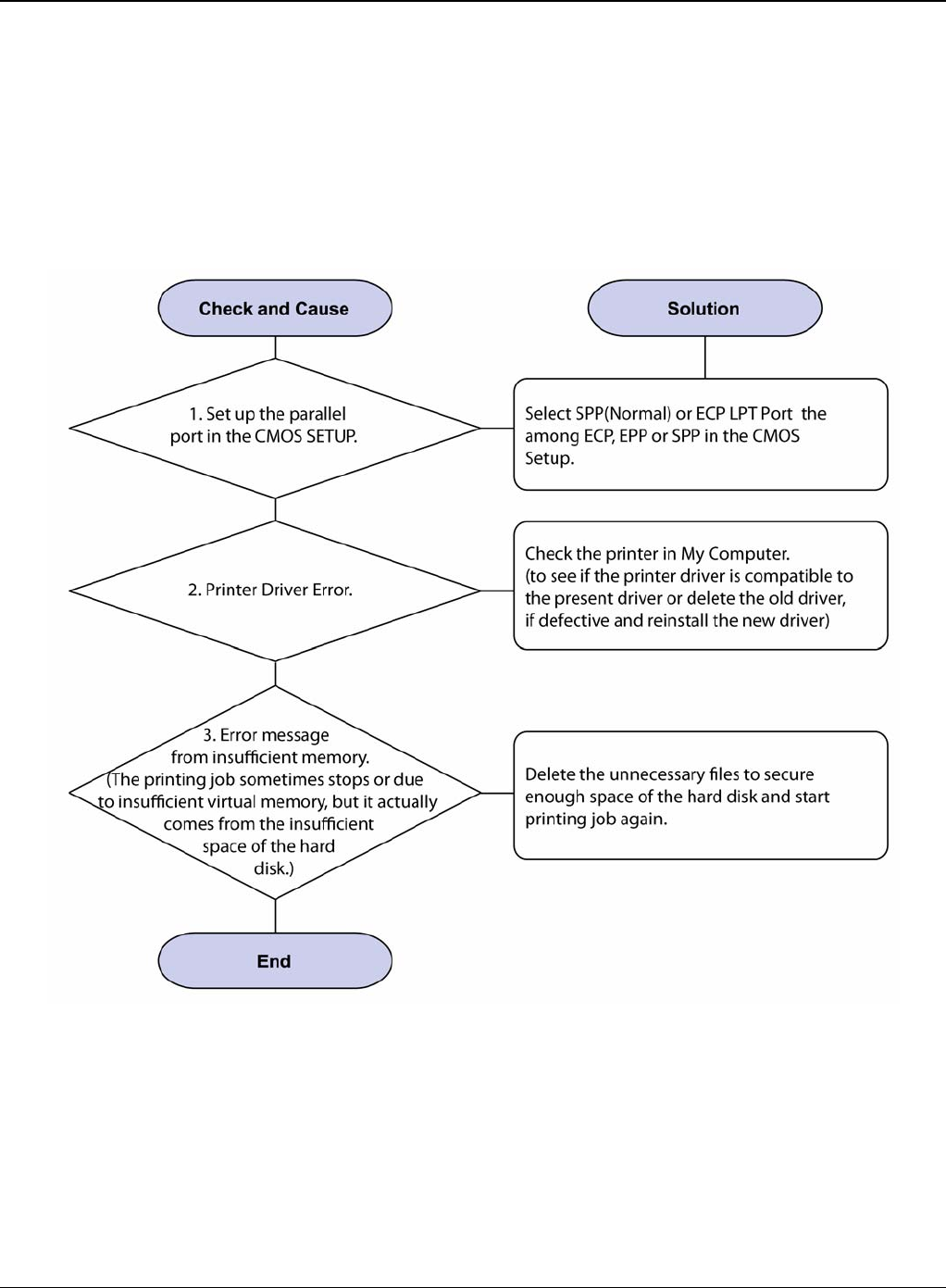
RAP 24 Abnormal Printing
Description
The printer is not working properly even when the cable has no problem (even after the cable is
replaced).
If the printer won’t work at all or the strange fonts are repeated, the printer driver may be defective
or setup in the CMOS Setup.
Figure 1
Status Indicator RAPs
2-40 5/08 Phaser 3435
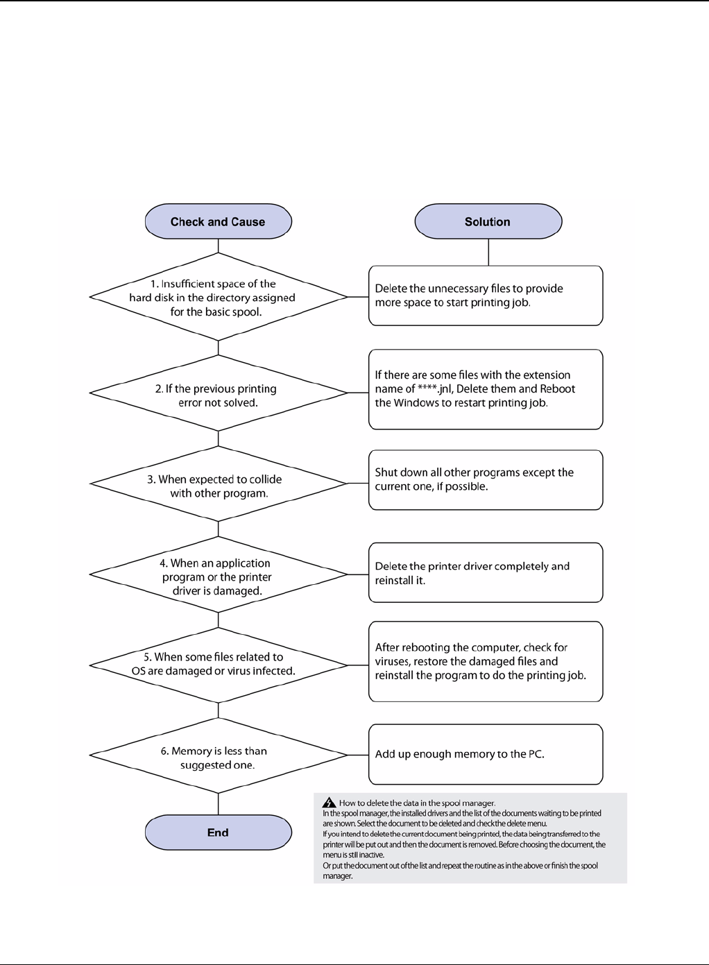
RAP 25 SPOOL Error
Description
To spool which stands for "simultaneous peripheral operations online" a computer document or
task list (or "job") is to read it and store it, usually on a hard disk or larger storage medium so that
it can be printed or otherwise processed at a more convenient time (for example, when a printer
is finished printing its current document).
Figure 1
Status Indicator RAPs
Phaser 3435 5/08 2-41
RAP 26 Multi-Feed Error
Figure 1
Status Indicator RAPs
2-42 5/08 Phaser 3435
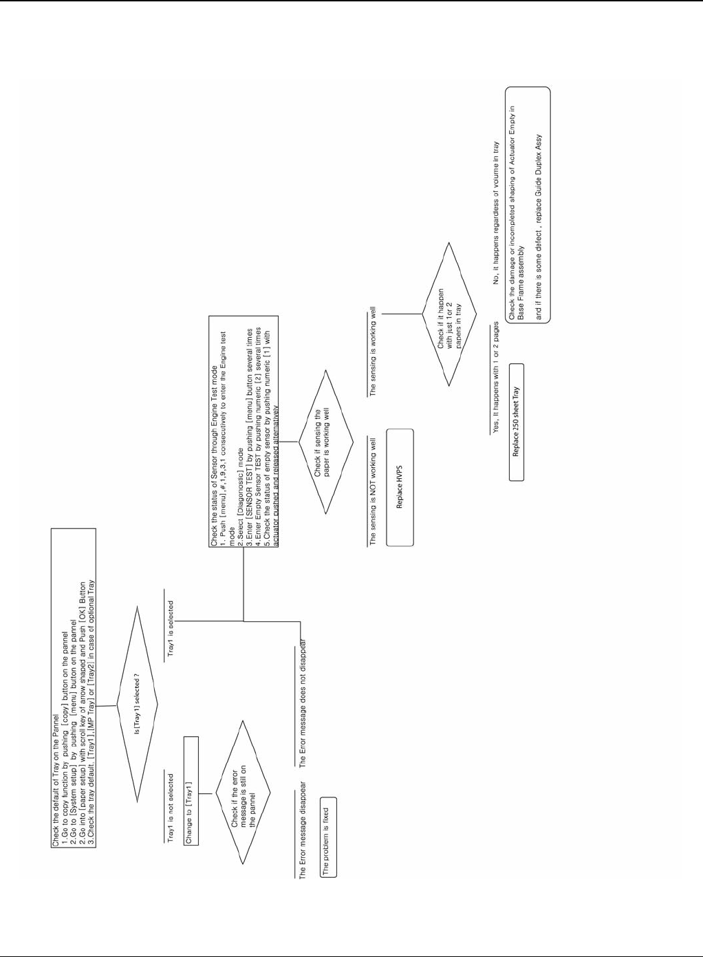
RAP 27 No Paper/Add Paper Error
Figure 1
Status Indicator RAPs
Phaser 3435 5/08 2-43
RAP 28 Open Cover Error
Figure 1
Status Indicator RAPs
2-44 5/08 Phaser 3435
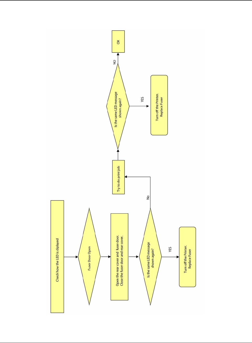
RAP 29 Fuser Door Open
Figure 1
Status Indicator RAPs
Phaser 3435 5/08 2-45
RAP 30 Audible Noise
Figure 1
Status Indicator RAPs
2-46 5/08 Phaser 3435
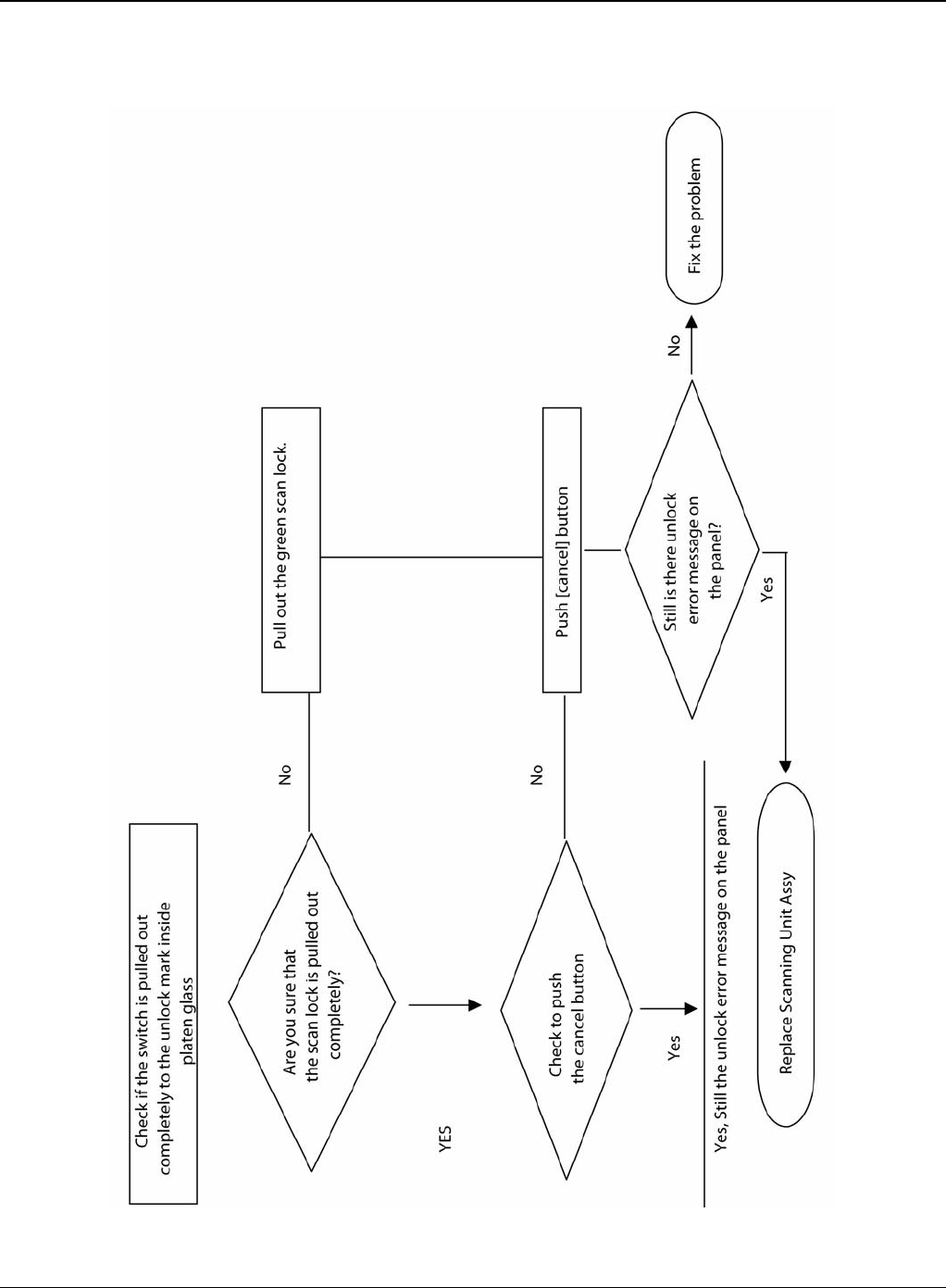
RAP 31 Scan Lock Error
Figure 1

Image Quality
Phaser 3435 5/08 3-1
3 Image Quality
IQ 1 Test Patterns .................................................................................................................... 3-3
IQ 2 Abnormal Image Printing and Defective Roller ................................................................. 3-5
IQ 3 Vertical Black Line and Band ............................................................................................ 3-6
IQ 4 Vertical White Line ............................................................................................................ 3-7
IQ 5 Horizontal Black Band ...................................................................................................... 3-8
IQ 6 Black/White Spot .............................................................................................................. 3-9
IQ 7 Light Image ..................................................................................................................... 3-10
IQ 8 Dark Image or a Black Page ........................................................................................... 3-11
IQ 9 Uneven Density .............................................................................................................. 3-12
IQ 10 Background .................................................................................................................. 3-13
IQ 11 Ghost (1) ....................................................................................................................... 3-14
IQ 12 Ghost (2) ....................................................................................................................... 3-16
IQ 13 Ghost (3): Fuser ........................................................................................................... 3-17
IQ 14 Stains on the Face of Page .......................................................................................... 3-18
IQ 15 Stains on Back of Page ................................................................................................ 3-19
IQ 16 Blank Page Print Out (1) ............................................................................................... 3-20
IQ 17 Blank Page Print Out (2) ............................................................................................... 3-21
IQ 18 Wrong Print Position ..................................................................................................... 3-22
IQ 19 Curved Vertical Line ..................................................................................................... 3-23
IQ 20 Signs and Measures of Poor Toner Cartridge .............................................................. 3-24
IQ 21 Low Toner ..................................................................................................................... 3-27

Image Quality
3-2 5/08 Phaser 3435
This page is intentionally blank

Image Quality
Phaser 3435 5/08 3-3
IQ 1 Test Patterns
This product has the several sample patterns for maintenance. With the sample patterns, check
the existence of the abnormality. The patterns help to regularly maintain the product.
Printing a Demo Page
Print a demo page or a configuration sheet to make sure that the printer is operating correctly.
Press the Menu button to select (Information -> Demo Page).
Figure 1
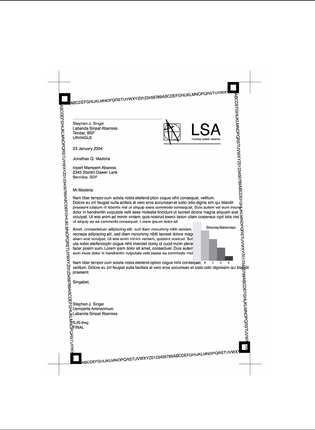
Image Quality
3-4 5/08 Phaser 3435
Sample Tests Patterns
The sample patterns shown below are the standard test patterns used in the factory.The life of the
print cartridge, developer cartridge and printing speed are measured with the pattern shown below
(5%). The A4 ISO 19752 standard pattern samples are reproduced reduced to 70% of the actual
A4size.
Figure 2
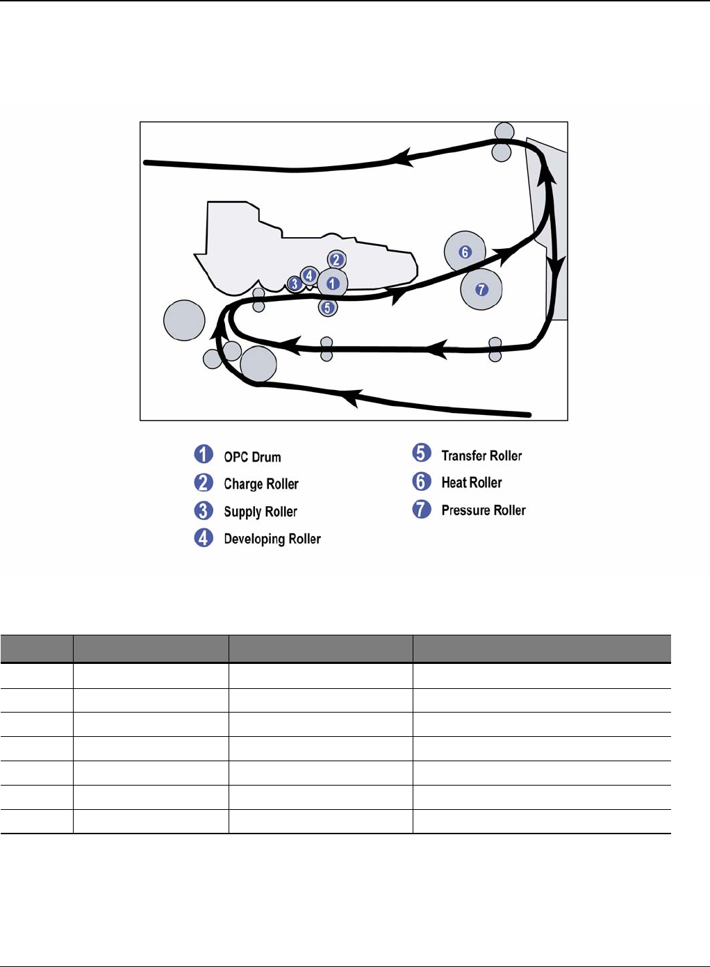
Image Quality
Phaser 3435 5/08 3-5
IQ 2 Abnormal Image Printing and Defective Roller
If abnormal image prints periodically, check the parts shown below.
Figure 1
No Roller Abnormal image period Kind of abnormal image
1 OPC Drum 75.5mm White spot, Block spot
2 Charge Roller 37.7mm Black spot
3 Supply Roller 44.9mm Horizontal density band
4 Develop Roller 35.2mm Horizontal density band
5 Transfer Roller 47.1mm Black side contamination/transfer fault
6 Heat Roller 77.8mm Black spot and fuser ghost
7 Pressure Roller 62.8mm / 50.24mm Black side contamination
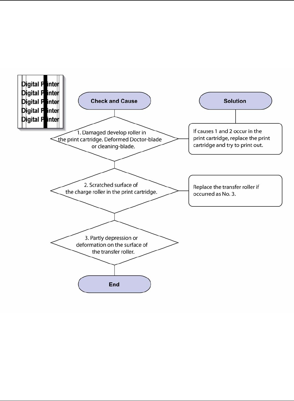
Image Quality
3-6 5/08 Phaser 3435
IQ 3 Vertical Black Line and Band
Description
1. Straight thin black vertical line occurs in the printing.
2. Dark black vertical band occur in the printing.
Figure 1
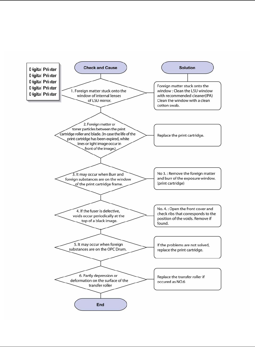
Image Quality
Phaser 3435 5/08 3-7
IQ 4 Vertical White Line
Description
White vertical voids in the image.
Figure 1
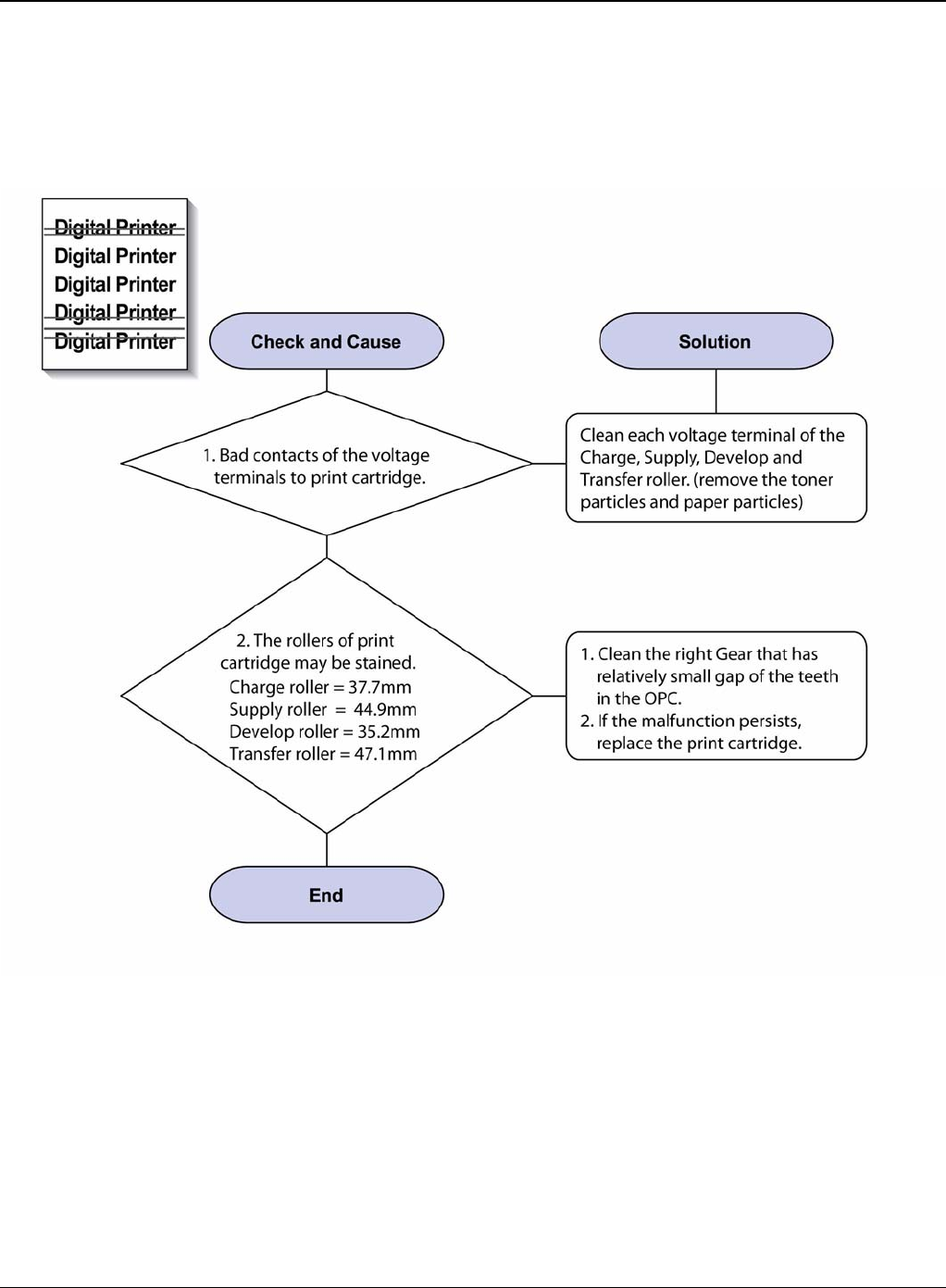
Image Quality
3-8 5/08 Phaser 3435
IQ 5 Horizontal Black Band
Description
Dark or blurry horizontal stripes occur in the printing.
Figure 1
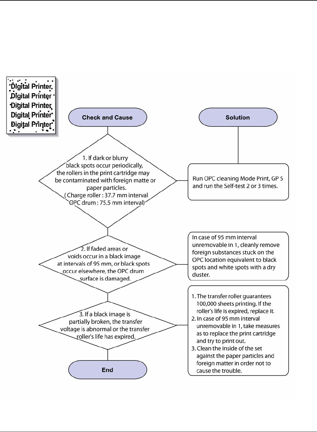
Image Quality
Phaser 3435 5/08 3-9
IQ 6 Black/White Spot
Description
1. Dark or blurry spots occur periodically in the printing
2. White spots occur periodically in the printing.
Figure 1
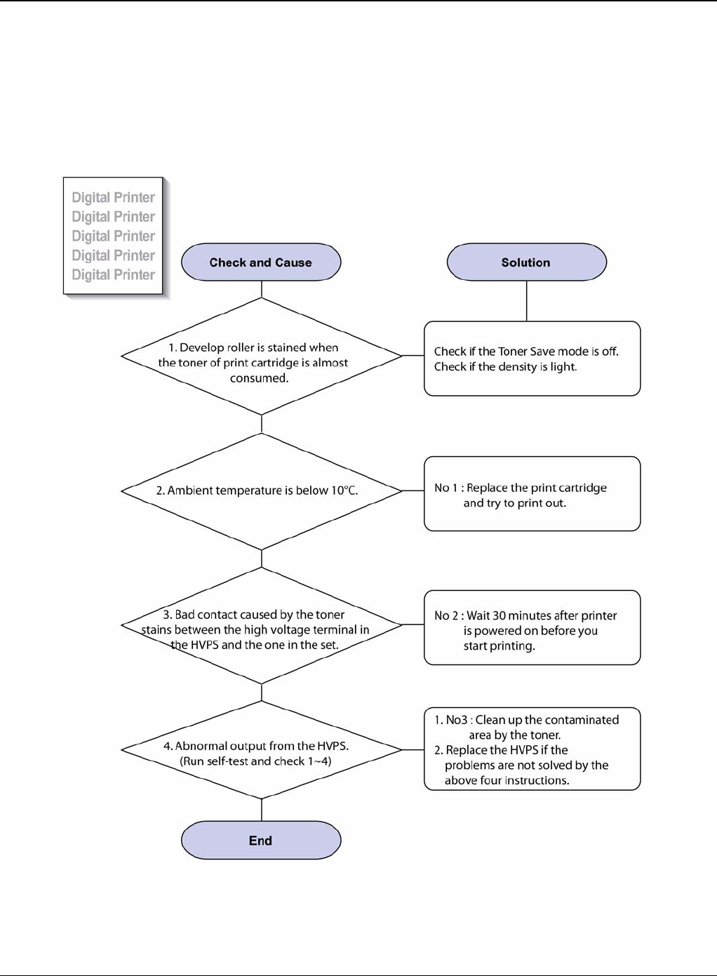
Image Quality
3-10 5/08 Phaser 3435
IQ 7 Light Image
Description
The printed image is light, with no ghost.
Figure 1
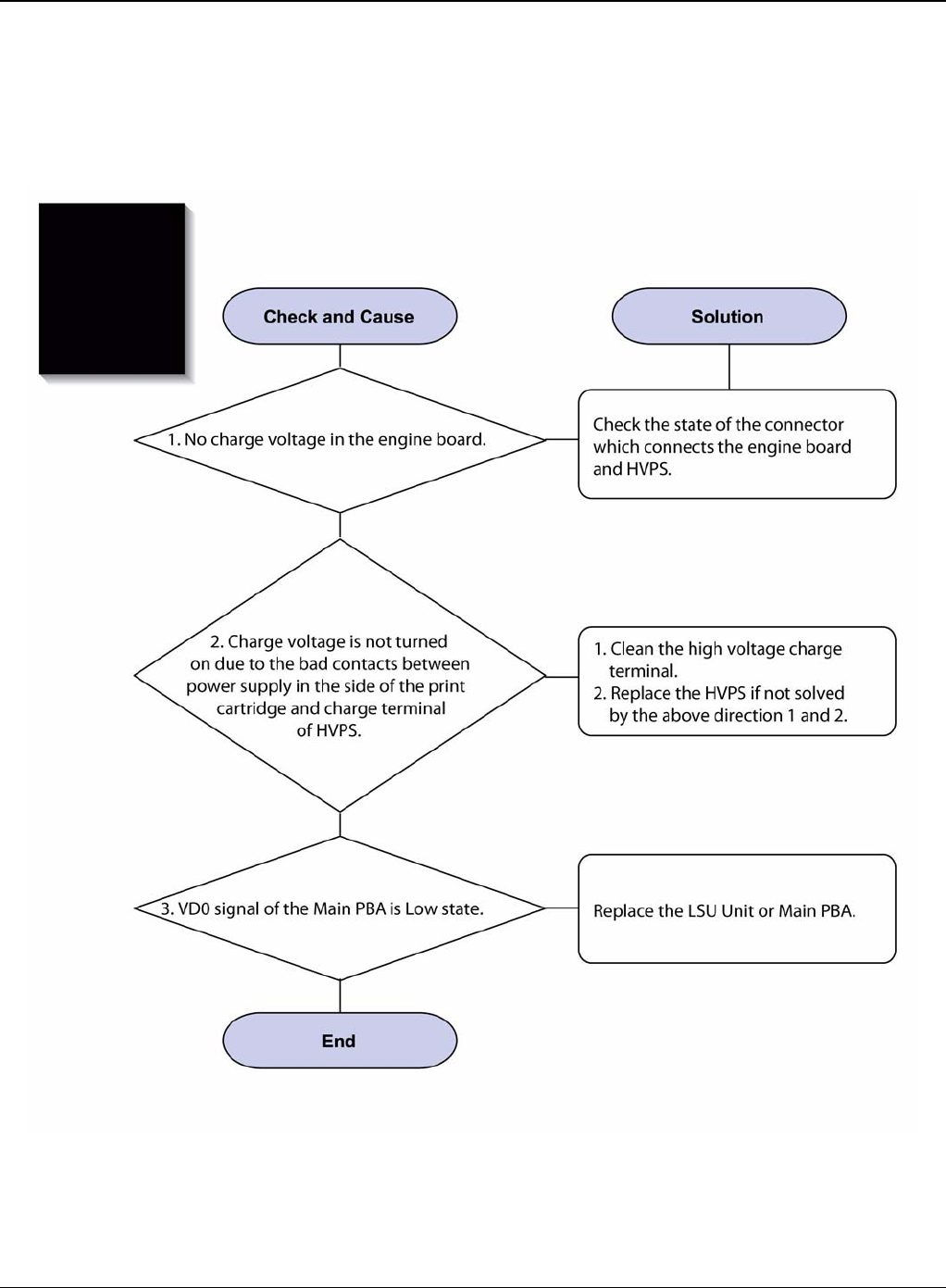
Image Quality
Phaser 3435 5/08 3-11
IQ 8 Dark Image or a Black Page
Description
The printed image is dark.
Figure 1
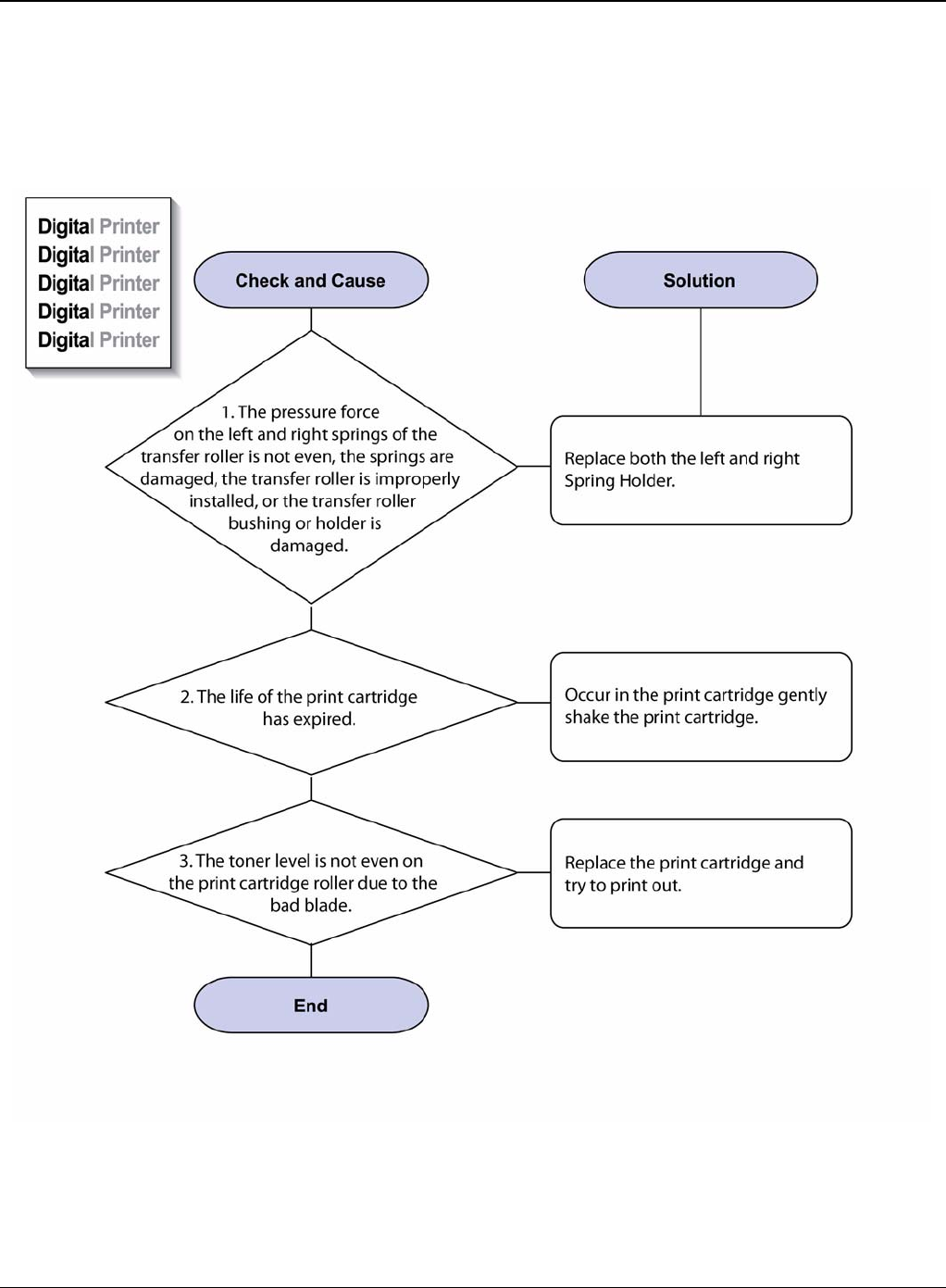
Image Quality
3-12 5/08 Phaser 3435
IQ 9 Uneven Density
Description
Print density is uneven between left and right.
Figure 1
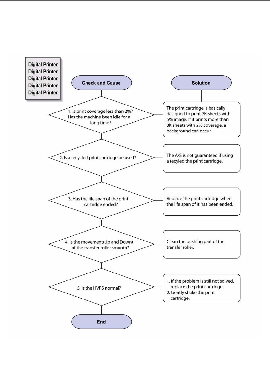
Image Quality
Phaser 3435 5/08 3-13
IQ 10 Background
Description
Light dark background appears in whole area of the printing.
Figure 1
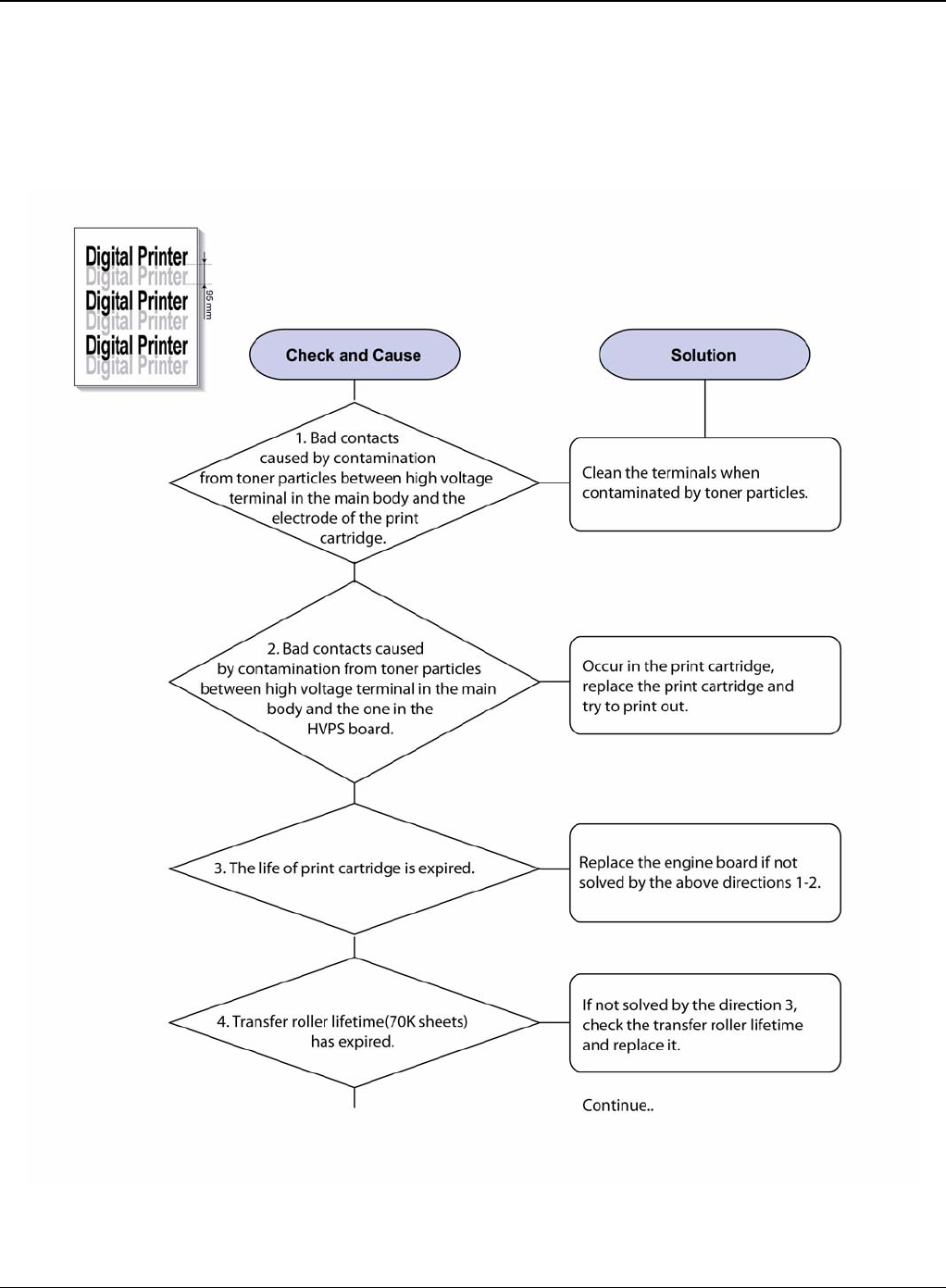
Image Quality
3-14 5/08 Phaser 3435
IQ 11 Ghost (1)
Description
Ghost occurs at 95 mm intervals of the OPC drum in the whole printing.
Figure 1
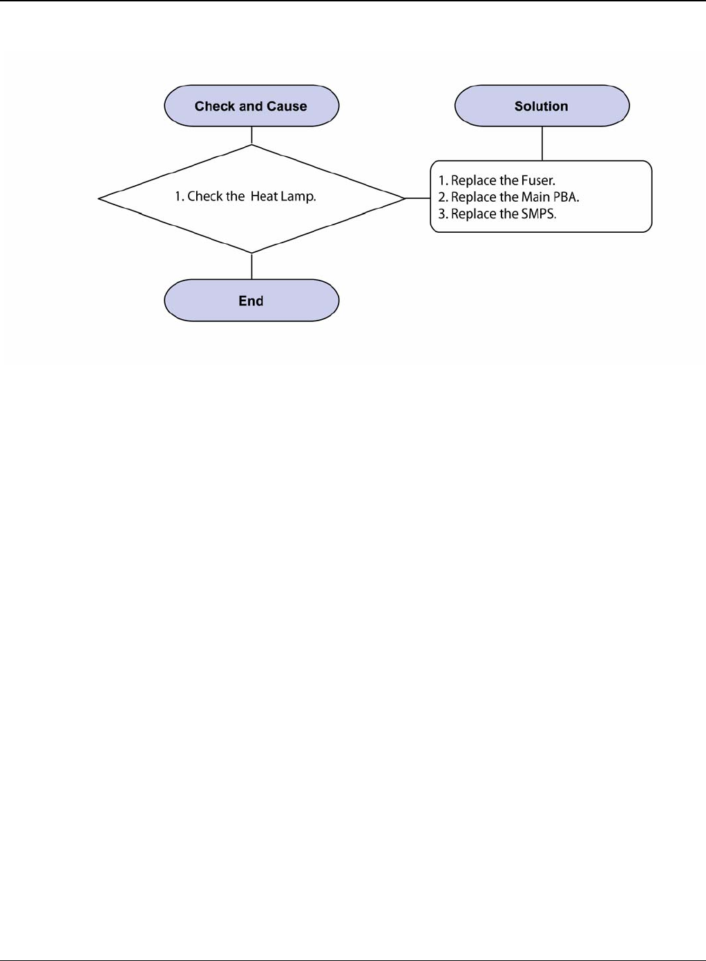
Image Quality
Phaser 3435 5/08 3-15
Figure 2
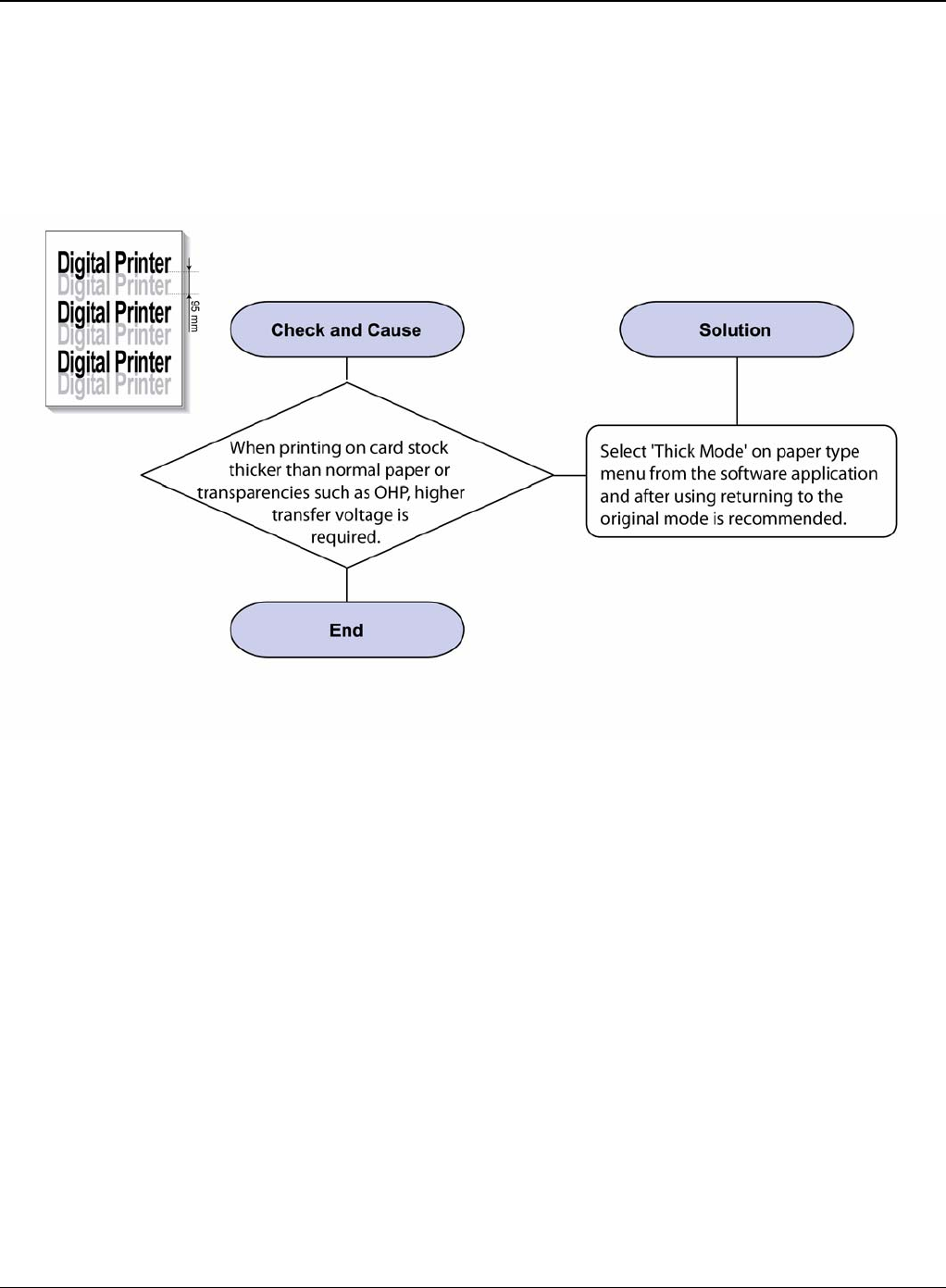
Image Quality
3-16 5/08 Phaser 3435
IQ 12 Ghost (2)
Description
Ghost occurs at 95 mm intervals of the OPC drum in the whole printing. (When printing on card
stock or transparencies using manual feeder)
Figure 1
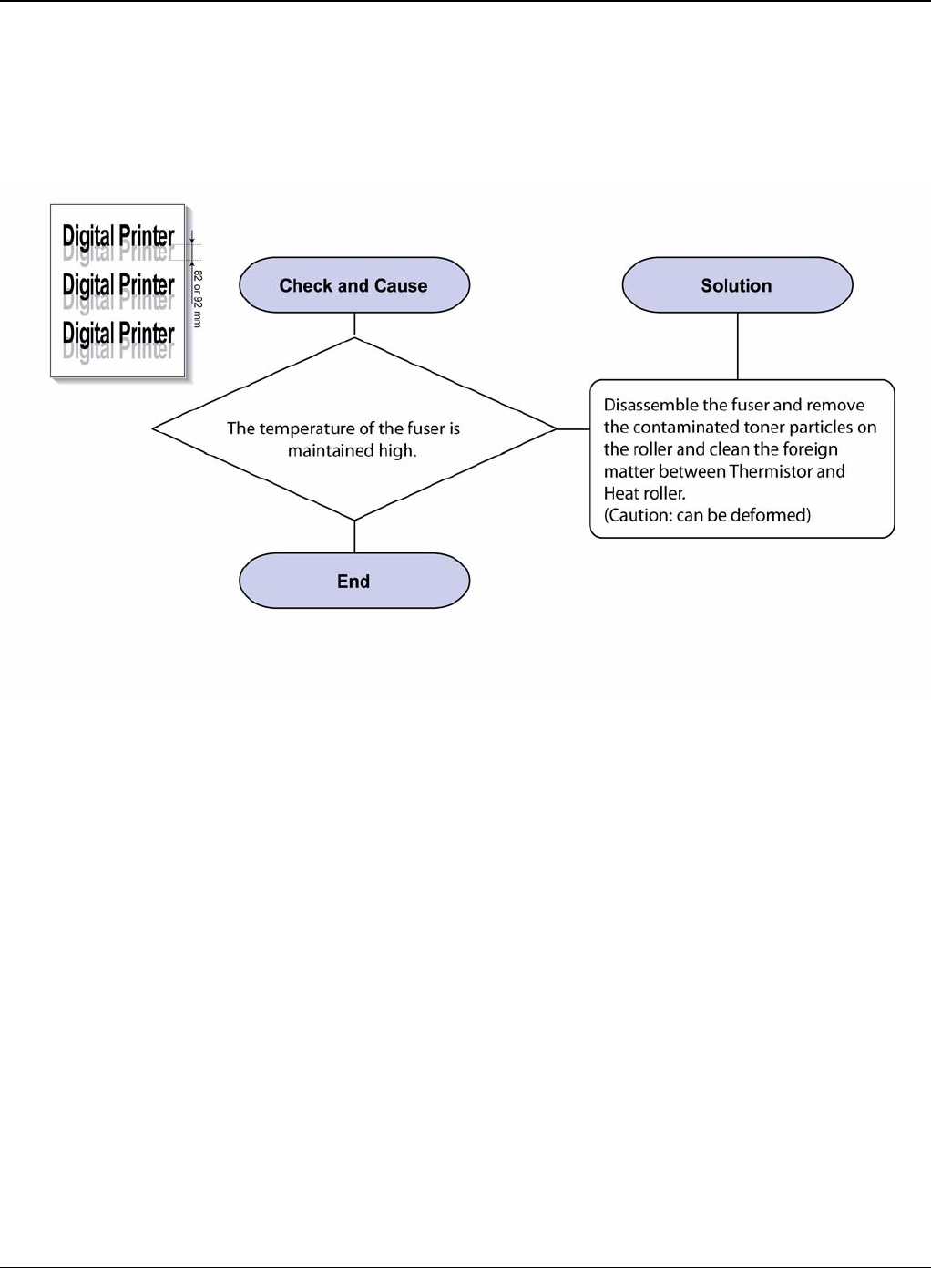
Image Quality
Phaser 3435 5/08 3-17
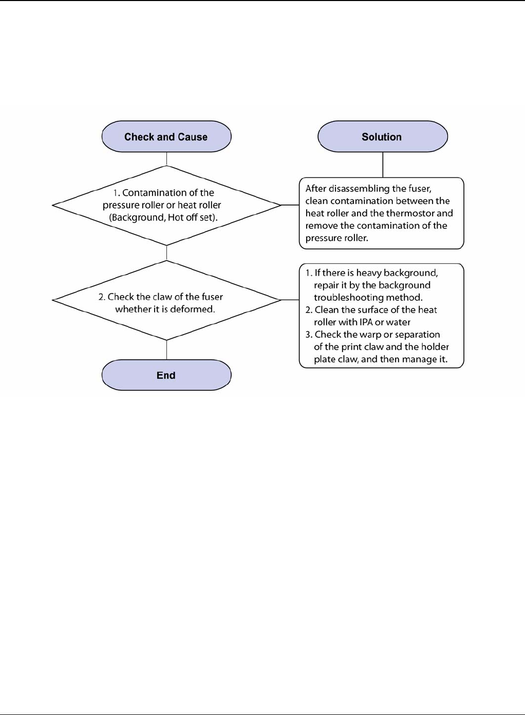
IQ 13 Ghost (3): Fuser
Description
Ghost occurs at 82 or 92 mm intervals.
Figure 1
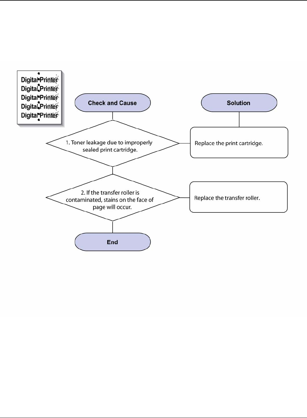
Image Quality
3-18 5/08 Phaser 3435
IQ 14 Stains on the Face of Page
Description
The background on the face of the printed page is stained.
Figure 1
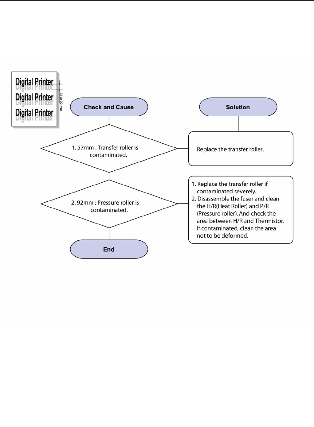
Image Quality
Phaser 3435 5/08 3-19
IQ 15 Stains on Back of Page
Description
The back of the page is stained at 57 or 92 mm intervals.
Figure 1
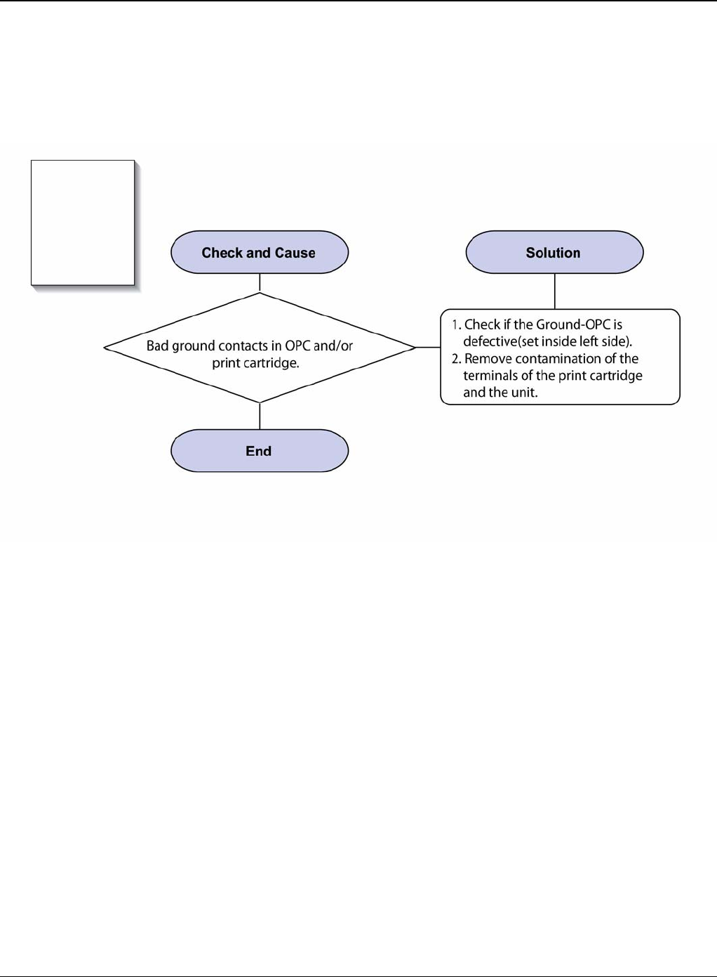
Image Quality
3-20 5/08 Phaser 3435
IQ 16 Blank Page Print Out (1)
Description
Blank page is printed.
Figure 1
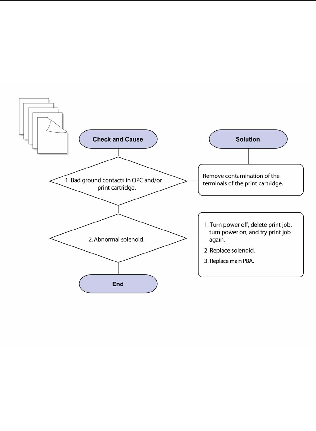
Image Quality
Phaser 3435 5/08 3-21
IQ 17 Blank Page Print Out (2)
Description
1. Blank page is printed.
2. One or several blank pages are printed
3. When the printer turns on, several blank pages print.
Figure 1
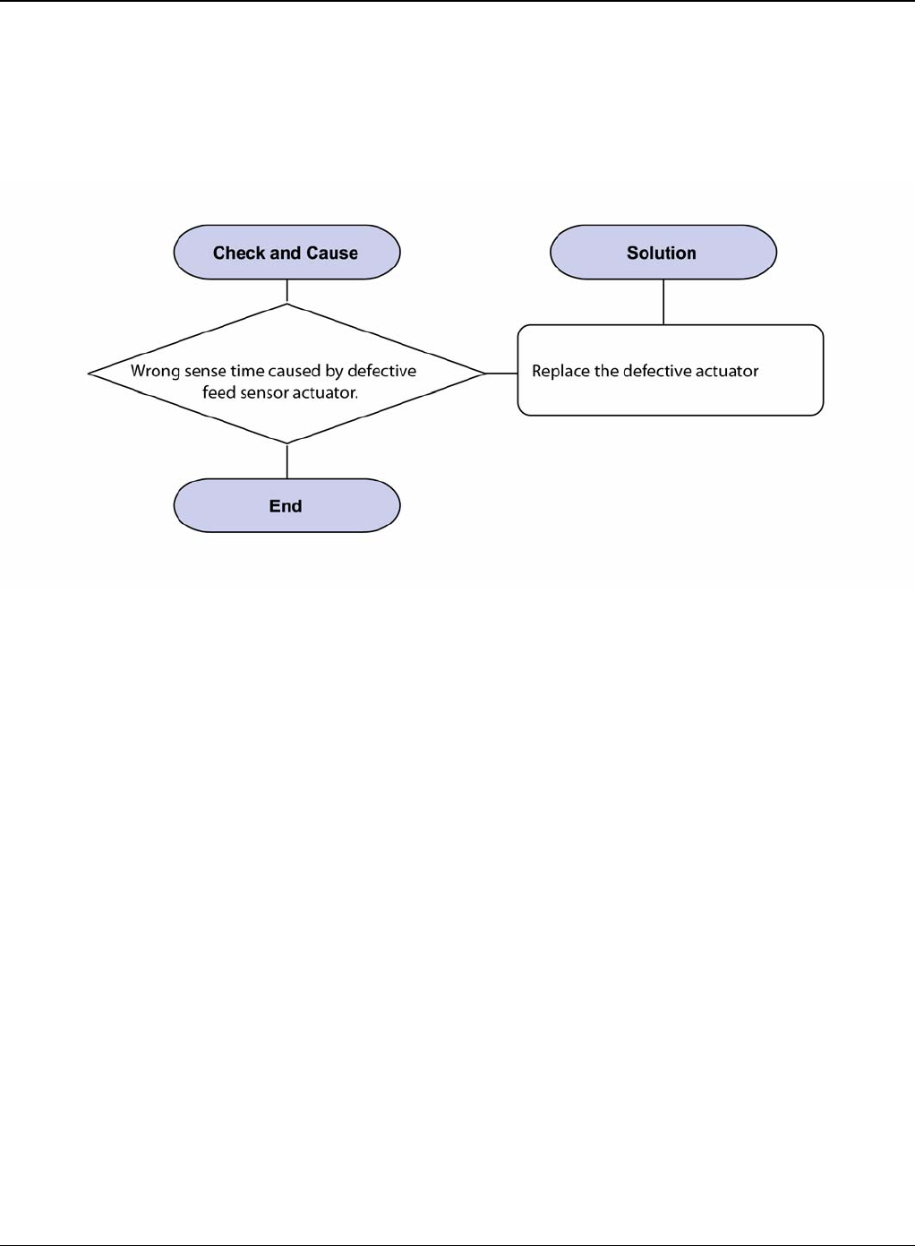
Image Quality
3-22 5/08 Phaser 3435
IQ 18 Wrong Print Position
Description
Printing begins at wrong position on the paper.
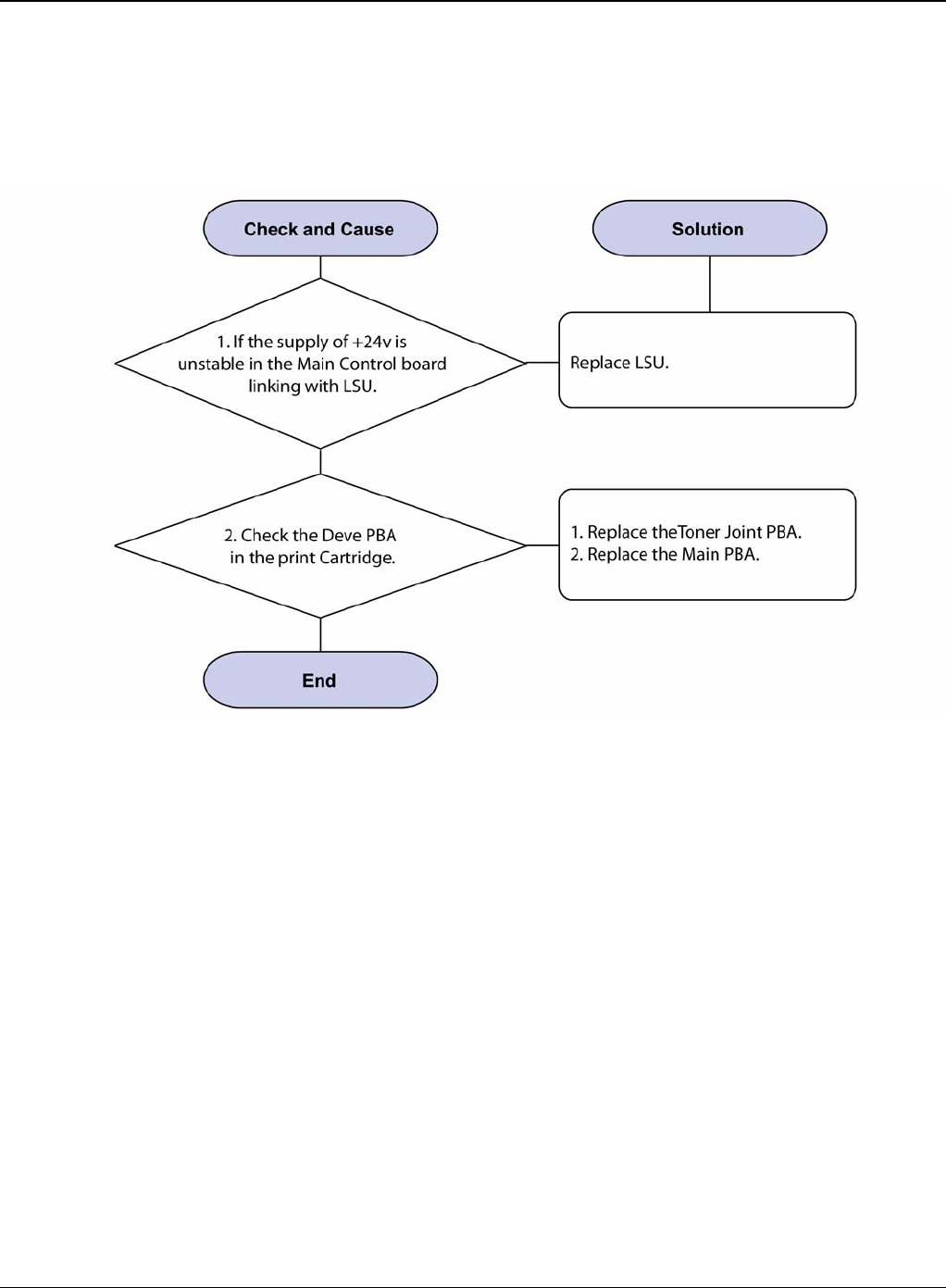
Image Quality
Phaser 3435 5/08 3-23
IQ 19 Curved Vertical Line
Description
When printing, vertical line get curved.
Figure 1

Image Quality
3-24 5/08 Phaser 3435
IQ 20 Signs and Measures of Poor Print Cartridge
Table 1:
Fault Signs Cause & Check Solution
Light image and par-
tially blank image
(The life is ended.)
• The printed image
is light or unclean
and untidy.
• Some part of the
image is not printed.
• Periodically a noise
as "tick tick" occurs.
1. If the image is light or
unclean and untidy printed
image -Shake the print car-
tridge and then recheck.
(1)NG: Check the weight of
the print cartridge
(2)OK: Lack of toner, so the
life is nearly closed.
2. Some part of image is not
printed -Shake the print car-
tridge and then recheck.
(1)NG: Check the weight of
the print cartridge and clean
the LSU window with a cotton
swab, then recheck.
(2)OK: Lack of toner, so the
life is nearly closed.
3. Periodically a noise as "tick
tick" occurs - Measure the
cycle and the weight of the
print cartridge.
4. White vertical stripes on the
whole screen or partly: Check
the weight of the print car-
tridge.
1. All of 1, 2, 3 above-If it
become better by shaking,
replace with a new print car-
tridge after 50-100 sheets in the
closing state of the life span.
2. In case of 2-If it becomes bet-
ter after cleaning the LSU win-
dow, then the print cartridge is
normal. (Because of foreign
substance on the LSU window,
the image has not been printed
partly.)
3. In case of 3-If the cycle of
noise is about 2 seconds, the
toner inside the print cartridge
has been nearly exhausted.
(Purchase and replace with a
new print cartridge after using
about 200 sheets at the point of
occurrence)
4. In case of 3-This is a phe-
nomenon caused by lack of
toner, so replace with a new
print cartridge.
Toner Contamina-
tion • Toner is fallen on
the papers periodi-
cally.
• Contaminated with
toner on prints partly
or over the whole
surface.
1. Toner is fallen on the paper
periodically.
(1)Check the cycle of the fall-
ing of the toner.
(2)Check the appearance of
both ends of the print car-
tridge OPC drum.
2.The centre of the printed
matter is contaminated with
toner.
(1)Check whether foreign
substances or toner are stuck
to the terminal (contact point)
of the print cartridge.
(2)Check whether the state of
the terminal assembly is nor-
mal.
1. If both ends of the OPC drum
are contaminated with toner:
Check the life of the print car-
tridge.
2. Check whether it could be
recycled.
3. If it cannot be recycled:
Replace the print cartridge.

Image Quality
Phaser 3435 5/08 3-25
White Black spot • Light or dark black
dots on the image
occur periodically. •
White spots occur in
the image periodi-
cally.
1. If light or dark periodical
black dots occur, this is
because the print cartridge
rollers are contaminated with
foreign substance or paper
particles.
(1)38mm interval: Charged
roller
(2)95mm interval: OPC cycle
2. If white spots occur in a
black image at intervals of
95mm, or black spots occur
elsewhere, the OPC drum is
damaged or foreign sub-
stance is stuck to the surface.
3. If a black and white or
graphic image is partially bro-
ken at irregular intervals, the
transfer roller's life has been
expired or the transfer voltage
is abnormal.
1. In case of 1 above -Run OPC
Cleaning Mode Print 4-5 times
repeatedly to remove, refer to
GP 5. Especially check foreign
substance on the OPC surface,
then remove them with a clean
gauze moistened with IPA (Iso-
propyl Alcohol) not to damage
OPC if necessary. Never use
usual alcohol.
2. In case of 2 If they are not
disappeared by running OPC
Cleaning Mode Print 4-5 times.:
at intervals of 38mm -Replace
the print cartridge.: at intervals
of 95mm - Remove foreign sub-
stance.: Broken image -Replace
the print cartridge according to
carelessness.
3. In case of 3 -Exchange the
transfer roller because the life of
the transfer roller in use has
been expired. (Check the trans-
fer voltage and readjust if differ-
ent.)
Recycled product • Poor appearance
of the print cartridge.
• Unclean and rough
printouts. • Bad
background in the
image.
1. Poor appearance of the
print cartridge.
(1)Check the damage to label
and whether different materi-
als are used.
(2)Check the appearance of
parts of the print cartridge,
such as frame, hopper.
2. Unclean and rough print-
outs.
(1)Check whether foreign
substance or toner are stuck
to the terminal (contact point)
of the print cartridge.
(2)Check whether the state of
the terminal assembly is nor-
mal.
1. In case of 1
(1)If there is an evidence of dis-
assembling the print cartridge.
(2)If materials other than normal
parts of the print cartridge are
added or substituted.
2. In case of 2 -If there are any
abnormality in connection with
the situation of 1.
(1)It occurs when the print car-
tridge is recycled over 2 times.
(2)If toner nearly being expired
are collected to use, it is judged
as the recycled print cartridge.
Table 1:
Fault Signs Cause & Check Solution

Image Quality
3-26 5/08 Phaser 3435
Ghost & Image Con-
tamination • The printed image
is too light or dark, or
partially contami-
nated black. • Totally
contaminated black.
(Black image printed
out) • The density of
printouts is too dark
and ghost occurs.
1. The printed image is too
light or dark, or partially con-
taminated black.
(1)Check whether foreign
substance or toner are stuck
to the terminal (point of con-
tact) of the print cartridge.
(2)Check whether the terminal
assembly is normal.
2. Totally contaminated black.
(Black image printed out)
(1)Check whether foreign
substances are stuck to the
terminal (point of contact) of
the print cartridge and the
state of assembly. (Espe-
cially check the charged roller
terminal.)
3. The printed image is dark
and ghost occurs.
(1)Check foreign substance
attached to the terminal (point
of contact) of the print car-
tridge and the state of assem-
bly. (Especially check the
developing roller terminal.)
1. All of 1, 2, 3 above
(1)Remove toner and foreign
substances adhered to the con-
tact point of the print cartridge.
(2)The contact point of the unit
facing that of the print cartridge
also must be cleaned.
(3)If the terminal assembly is
unsafe: • Fully stick the terminal
to or reassemble it after disas-
sembling. • Disassemble the
side plate and push the terminal
to be stuck, then reassemble it.
2. In case of 2 It is a phenome-
non when the OPC drum of the
print cartridge is not electrically
charged. Clean the terminals of
the charged roller, then recheck
it.
3. In case of 3 It is a phenome-
non as the developing bias volt-
age of the print cartridge. Clean
the terminals of the developing
roller, then recheck it.
Table 1:
Fault Signs Cause & Check Solution
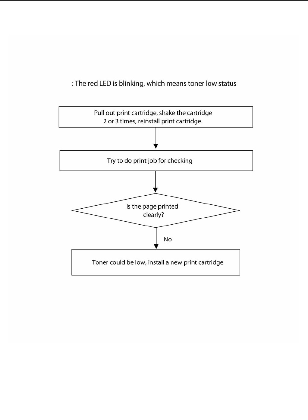
Image Quality
Phaser 3435 5/08 3-27
IQ 21 Low Toner
Figure 1

Image Quality
3-28 5/08 Phaser 3435
This page is intentionally blank

Repairs and Adjustments
Phaser 3435 5/08 4-1
4 Repairs and Adjustments
REP 1 Front Cover ................................................................................................................... 4-3
REP 2 MP Tray Assembly ....................................................................................................... 4-6
REP 3 Rear Cover ................................................................................................................... 4-8
REP 4 Fuser Assembly ......................................................................................................... 4-11
REP 5 Top Cover .................................................................................................................. 4-17
REP 6 OPE Unit .................................................................................................................... 4-19
REP 7 Side Cover (Left, Right) ............................................................................................. 4-21
REP 8 Shield Controller Assembly ........................................................................................ 4-25
REP 9 Drive Assembly .......................................................................................................... 4-28
REP 10 Duplex Drive Assembly ............................................................................................ 4-30
REP 11 Shield SMPS Assembly ........................................................................................... 4-32
REP 12 Connection PCB ...................................................................................................... 4-34
REP 13 Fuser Drive Assembly ............................................................................................... 4-36
REP 14 Fans .......................................................................................................................... 4-38
REP 15 Pick-up Roller Assembly ........................................................................................... 4-40
REP 16 Duplex Guide Housing (With Feed Roller) ................................................................ 4-42
REP 17 HVPS Housing ......................................................................................................... 4-44
REP 18 Cover Mid Front ....................................................................................................... 4-46
REP 19 MPF Housing ........................................................................................................... 4-47
REP 20 Feed Roller Parts ..................................................................................................... 4-49
REP 21 Pick Up Gear Assembly & Solenoids ........................................................................ 4-53
REP 22 Exit Roller ................................................................................................................. 4-55
REP 23 LSU .......................................................................................................................... 4-56
REP 24 Terminal ................................................................................................................... 4-57
REP 25 Transfer Roller Parts ................................................................................................ 4-58

Repairs and Adjustments
4-2 5/08 Phaser 3435
This page is intentionally blank
Repairs and Adjustments
Phaser 3435 5/08 4-3
REP 1 Front Cover
Parts List on: PL 3
WARNING
Switch off the electricity to the machine. Disconnect the power cord from the customer supply
while performing tasks that do not need electricity. Electricity can cause death or injury. Moving
parts can cause injury.
1. Take out the Cassette.
Figure 1
Repairs and Adjustments
4-4 5/08 Phaser 3435
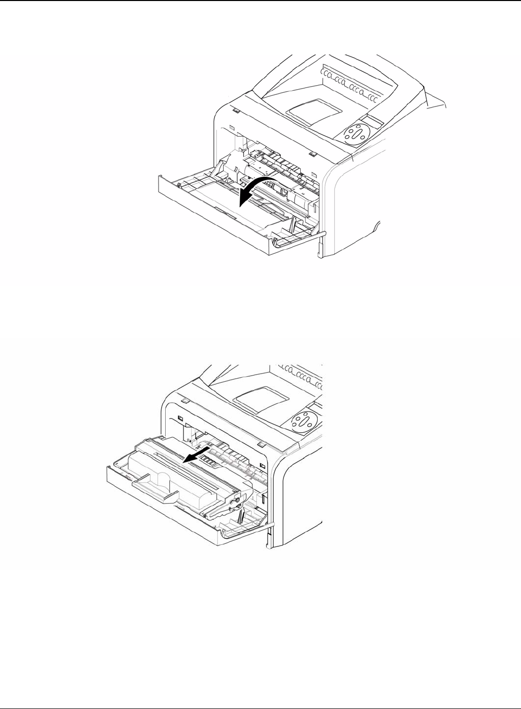
2. Open the Cover.
Figure 2
3. If necessary, remove the print cartridge.
Figure 3
Repairs and Adjustments
Phaser 3435 5/08 4-5
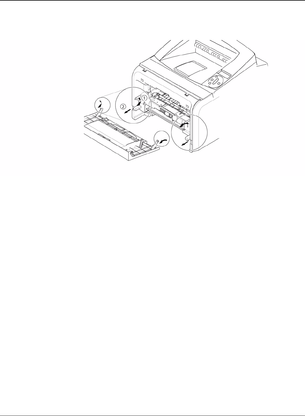
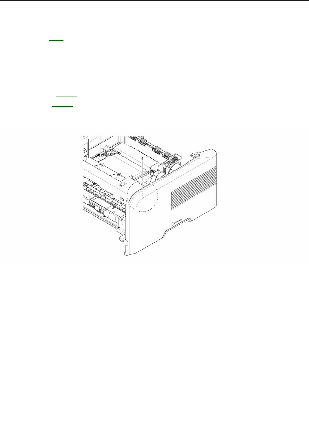
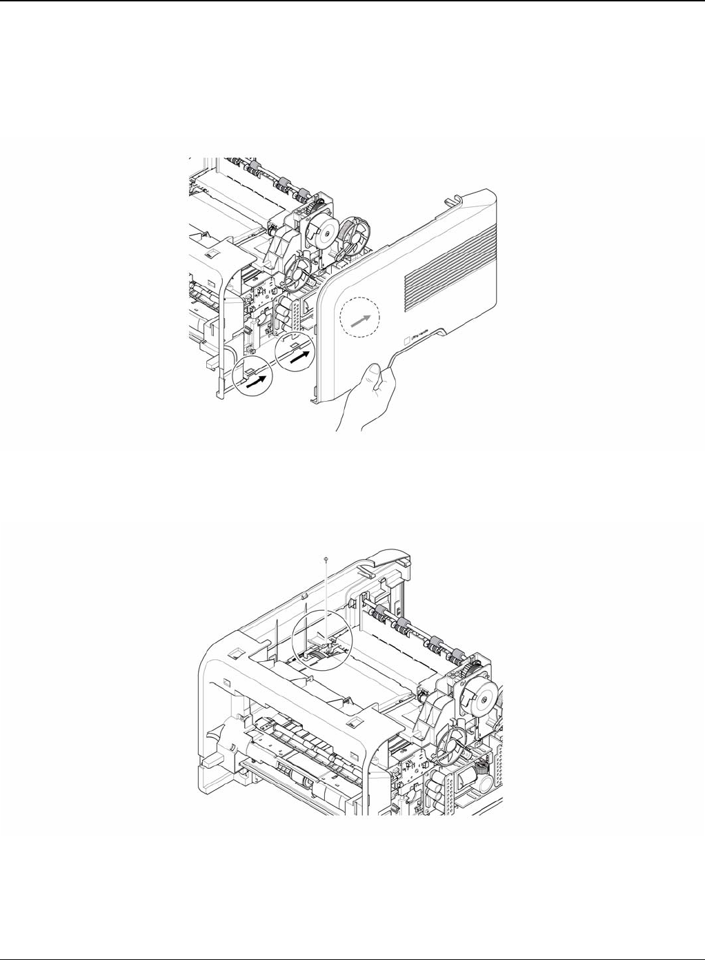
4. To remove the Front Cover, first pull the part below the both side of the Front Cover with a
light pressure to the direction of arrow.
Figure 4
Repairs and Adjustments
4-6 5/08 Phaser 3435
REP 2 MP Tray Assembly
Parts List on: PL 3
WARNING
Switch off the electricity to the machine. Disconnect the power cord from the customer supply
while performing tasks that do not need electricity. Electricity can cause death or injury. Moving
parts can cause injury.
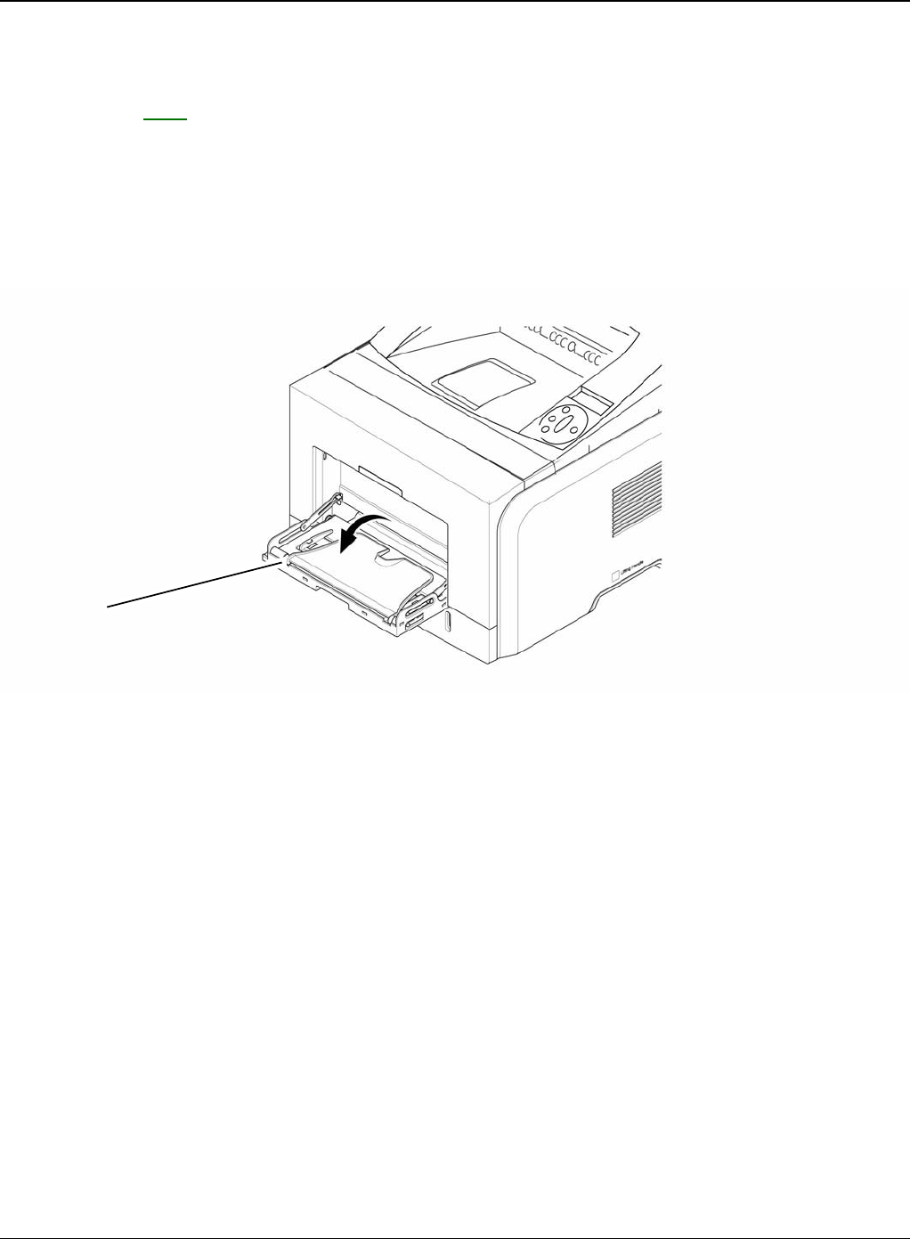
1. Open the MP Tray Assembly
Figure 1
MP tray assembly
Repairs and Adjustments
Phaser 3435 5/08 4-7
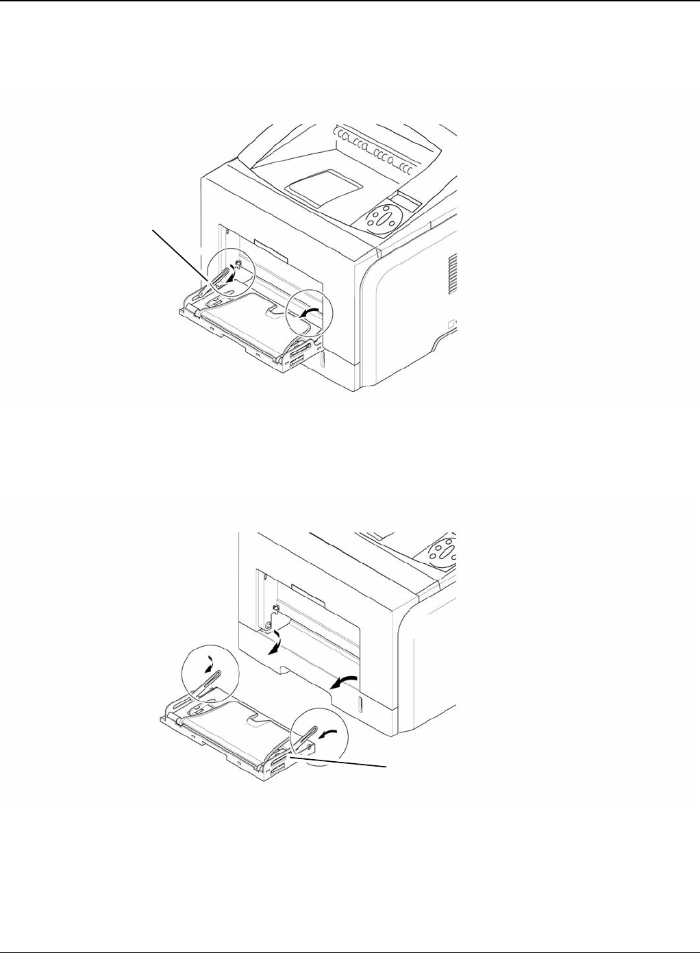
2. Pull the Tray Links from the both side of the Front Cover with a light pressure to the direction
of arrow.
Figure 2
3. Apply light pressure to the both side of the MP Tray Assembly and pull it in the direction of
arrow, as shown below.
Figure 3
Tray link
MP tray assembly
Repairs and Adjustments
4-8 5/08 Phaser 3435
REP 3 Rear Cover
Parts List on: PL 2
WARNING
Switch off the electricity to the machine. Disconnect the power cord from the customer supply
while performing tasks that do not need electricity. Electricity can cause death or injury. Moving
parts can cause injury.
1. Take out the Duplex Unit.
Figure 1
Duplex unit
Repairs and Adjustments
Phaser 3435 5/08 4-9
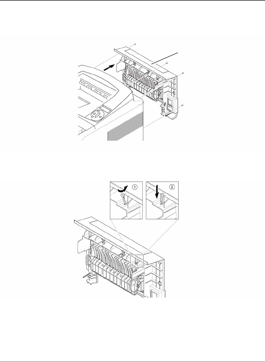
2. Remove the four screws securing the Rear Cover and then Release the Rear Cover from the
machine.
Figure 2
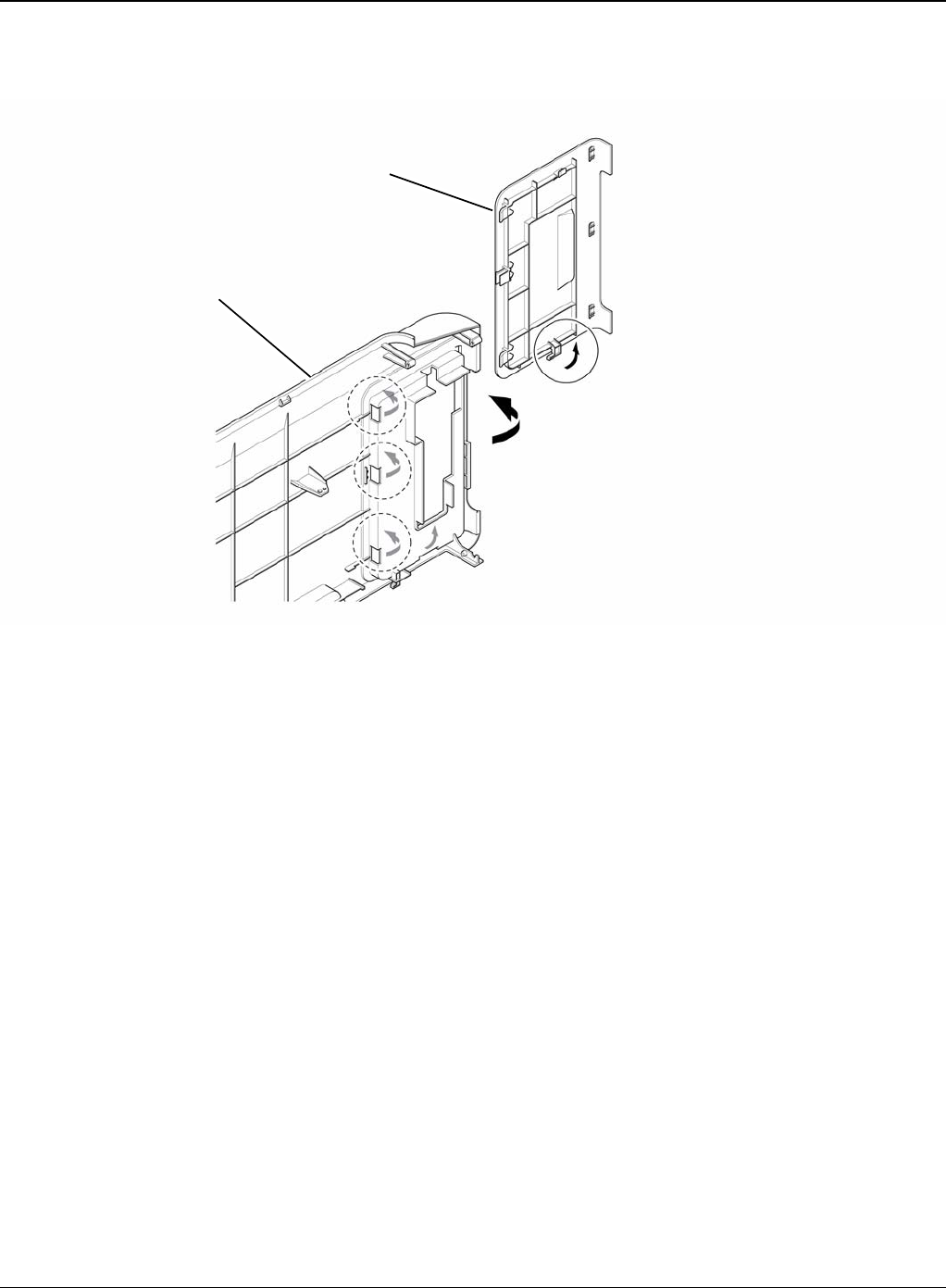
3. To remove the Face Up Cover, first release the Stopper Strap in the direction of arrow.
Figure 3
Rear cover
Stopper strap
Repairs and Adjustments
4-10 5/08 Phaser 3435
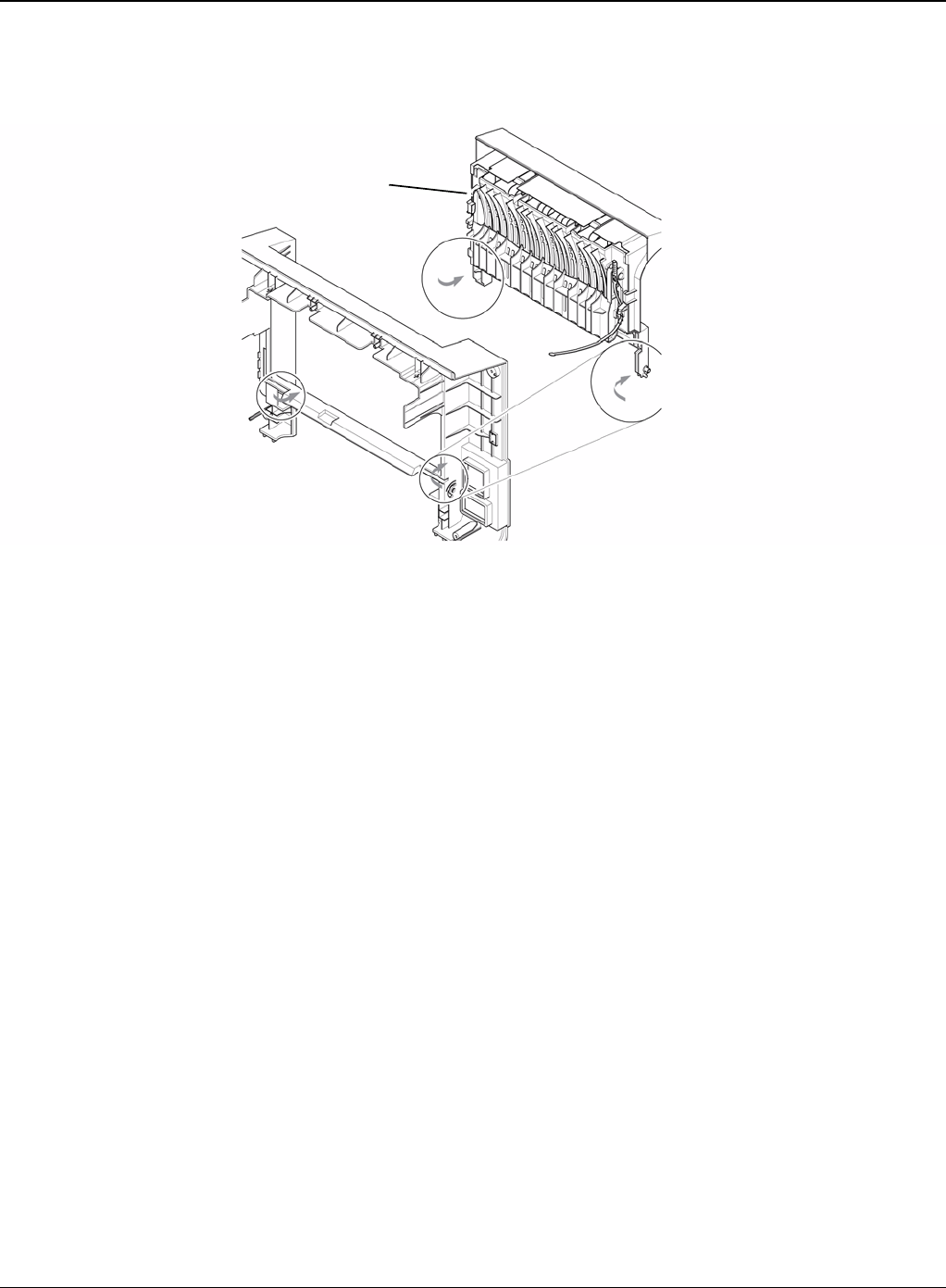
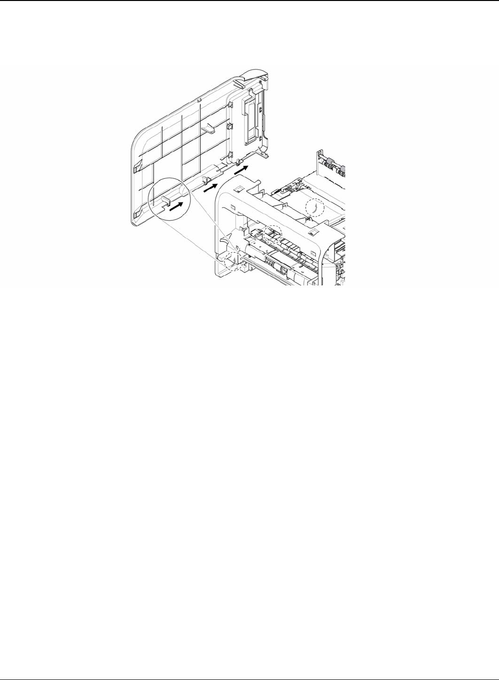
4. Unlatch the Face Up Cover from the Rear Cover and then release the Face Up Cover, as
shown below.
Figure 4
Face up cover
Repairs and Adjustments
Phaser 3435 5/08 4-11
REP 4 Fuser Assembly
Parts List on: PL 13 and PL 14
WARNING
Switch off the electricity to the machine. Disconnect the power cord from the customer supply
while performing tasks that do not need electricity. Electricity can cause death or injury. Moving
parts can cause injury. WARNING
Do not touch the fuser while it is hot.
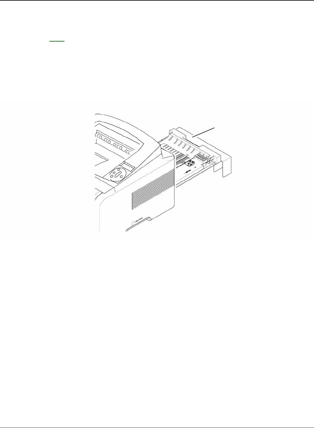
1. Before removing the Fuser Assembly, open the face up cover and open the guide output
fuser. Rear Cover, REP 3.
2. Remove the four screws securing the Fuser Assembly and then pull the Fuser Assembly.
Figure 1
Fuser assembly
Repairs and Adjustments
4-12 5/08 Phaser 3435
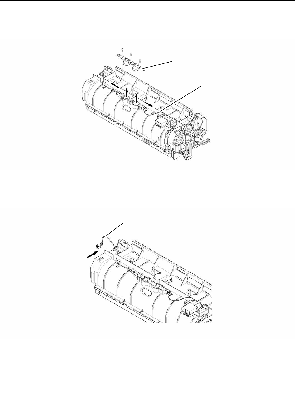
3. Release the CON Harness and REC Harness from the Thermostat and then remove the
three screws securing the Thermostat and remove it.
Figure 2
4. To remove the Electrodes, first release REC Harness from the left side of the Electrode and
then release the CON Harness from the right side of the Electrode, as shown below.
Figure 3
Thermostat
CON harness
REC harness
Repairs and Adjustments
Phaser 3435 5/08 4-13
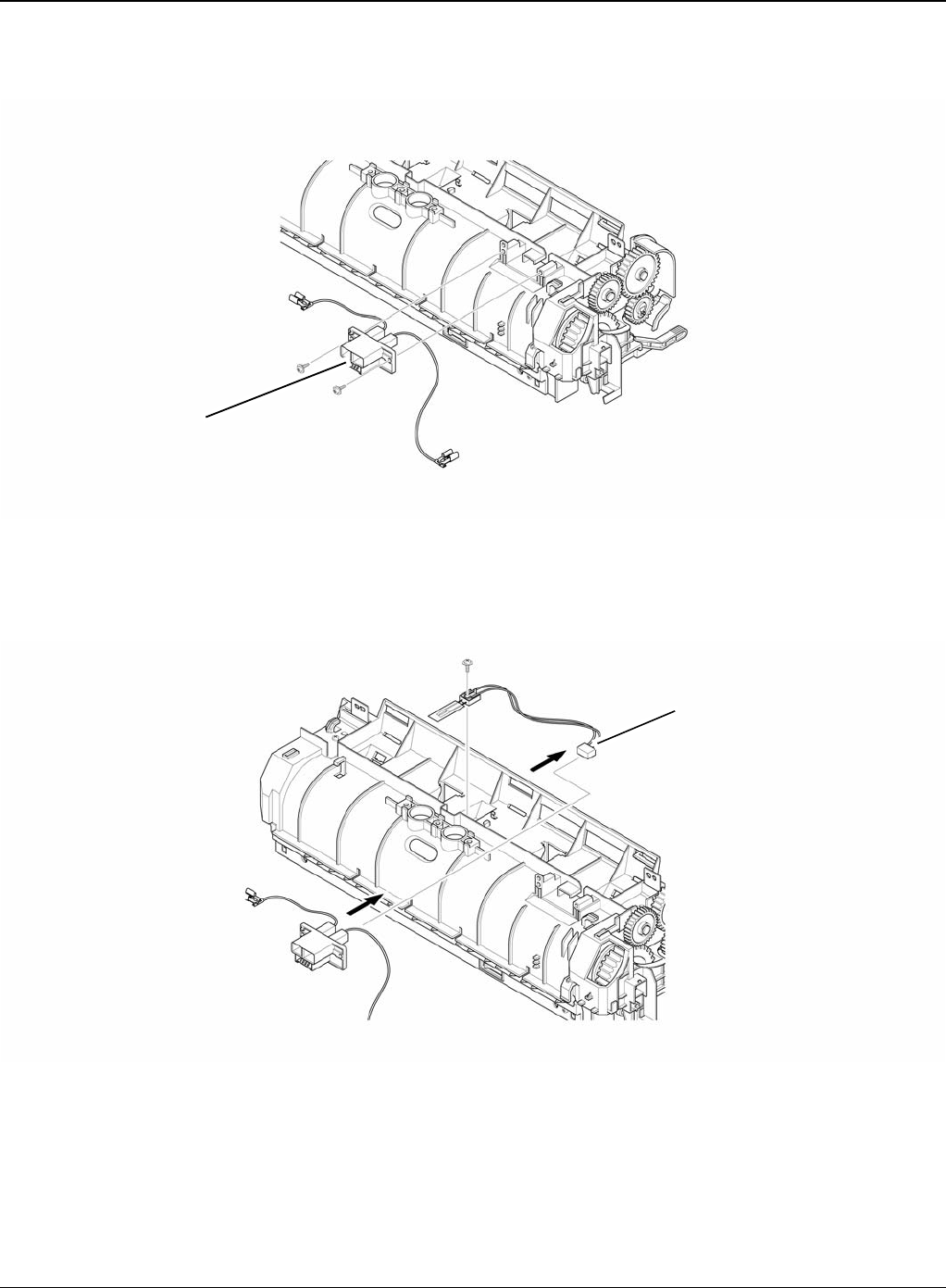
5. Remove the two screws securing the Input Guide and remove it.
Figure 4
6. Unplug the connector from the Input Guide and remove the one screw securing the Thermis-
tor and remove it.
Figure 5
Input guide
Thermistor
Repairs and Adjustments
4-14 5/08 Phaser 3435
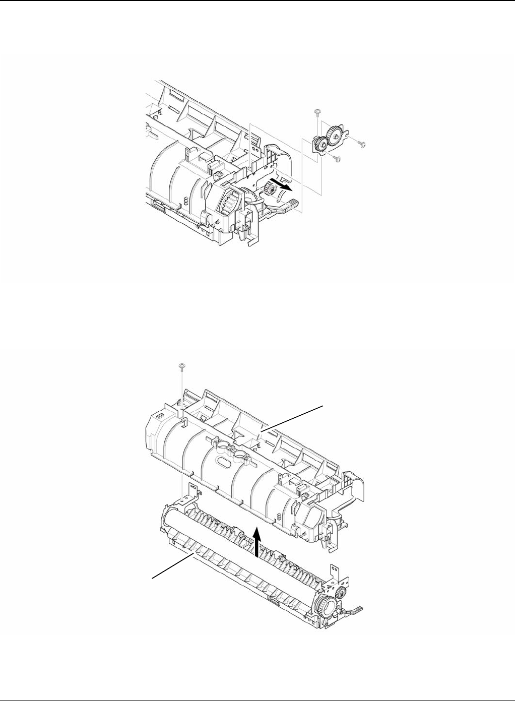
7. Remove the three screws securing the Idle Gear Bracket and remove it.
Figure 6
8. Remove the one screw securing the Fuser Cover and release the Fuser Cover from the
Fuser Frame.
Figure 7
Idle gear bracket
Fuser cover
Fuser frame
Repairs and Adjustments
Phaser 3435 5/08 4-15
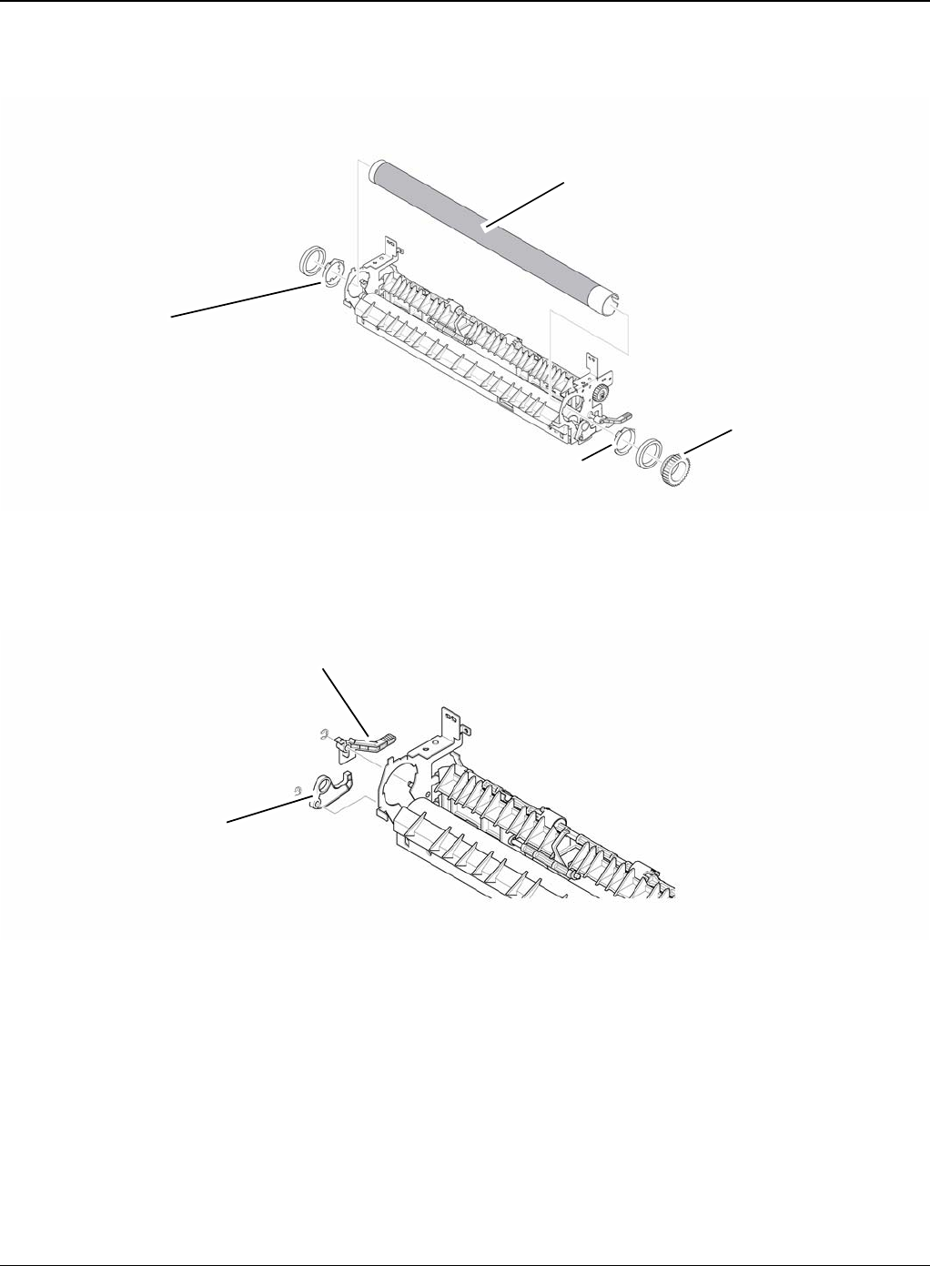
9. Release the Fuser Gear and HR Bush and then remove the Heat Roller, as shown below.
Figure 8
10.Remove the Jam Link Lever (L,R) and Jam Holder (L,R) and then remove the Pressure
Roller, as shown in figures 9 and 10.
Figure 9
Heat roller
HR bush
HR bush
Fuser gear
Jam holder
Jam link lever

Repairs and Adjustments
4-16 5/08 Phaser 3435
Figure 10
Jam holder
Jam link lever
Repairs and Adjustments
Phaser 3435 5/08 4-17
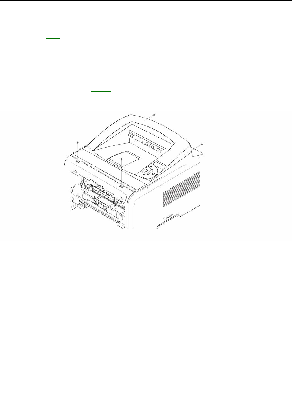
REP 5 Top Cover
Parts List on: PL 2
WARNING
Switch off the electricity to the machine. Disconnect the power cord from the customer supply
while performing tasks that do not need electricity. Electricity can cause death or injury. Moving
parts can cause injury.
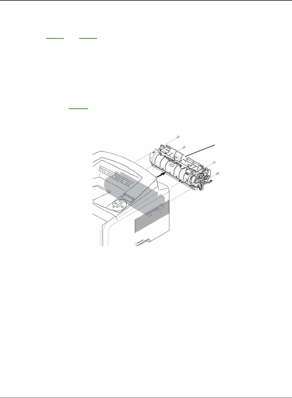
1. Before removing the Top Cover, remove the:
- Rear Cover (Left, Right), REP 3.
2. Remove the four screws securing the Top Cover, as shown below.
Figure 1
Repairs and Adjustments
4-18 5/08 Phaser 3435
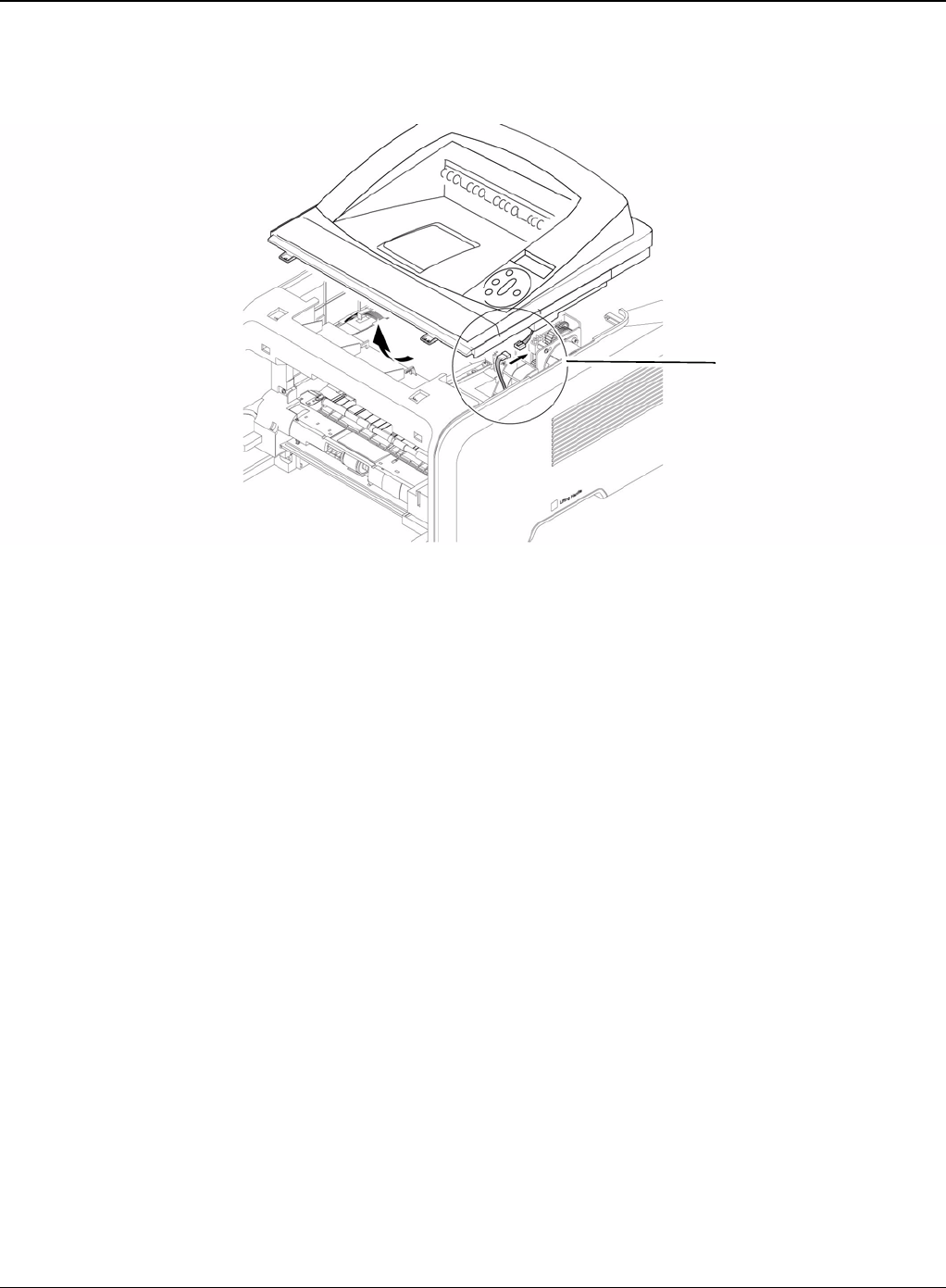
3. To remove the Top Cover, first lift the Top Cover with a light pressure to the direction of
arrow. Then unplug the OPE Harness, as shown below.
Figure 2
OPE harness
Repairs and Adjustments
Phaser 3435 5/08 4-19
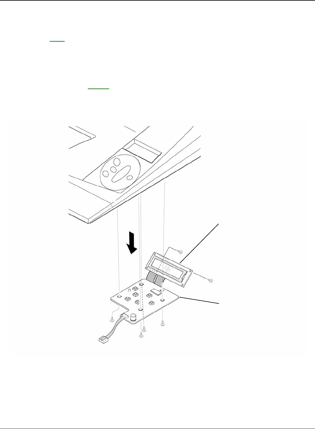
REP 6 OPE Unit
Parts List on: PL 5
WARNING
Switch off the electricity to the machine. Disconnect the power cord from the customer supply
while performing tasks that do not need electricity. Electricity can cause death or injury. Moving
parts can cause injury.
1. Remove the top cover, REP 5.
2. Remove the six screws securing the OPE PBA and LCD Panel to the Top Cover and remove
it, as shown below.
Figure 1
LCD panel
OPE PBA
Repairs and Adjustments
4-20 5/08 Phaser 3435
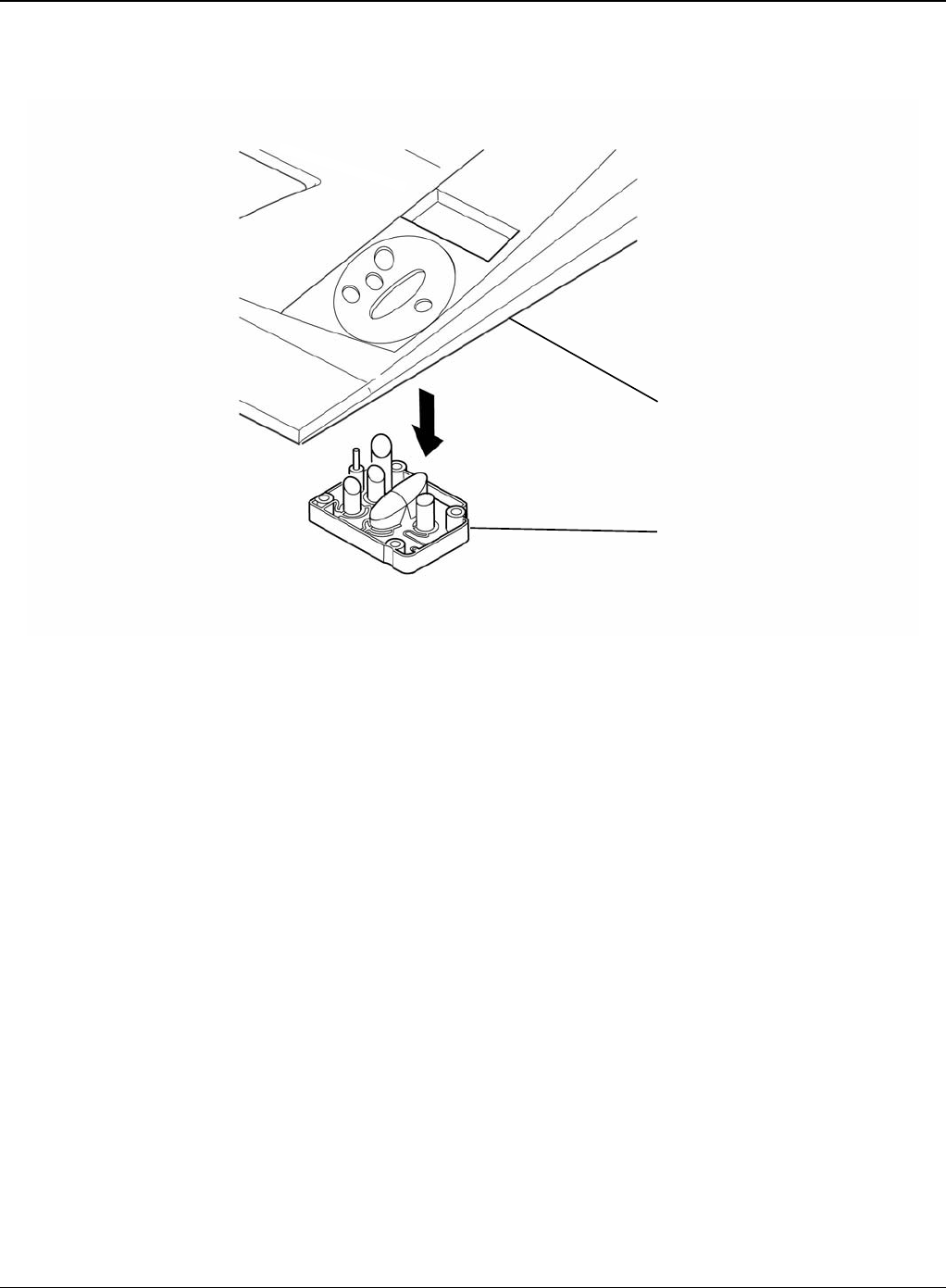
3. Release the key assembly.
Figure 2
Top cover
Key assembly
Repairs and Adjustments
Phaser 3435 5/08 4-21
REP 7 Side Cover (Left, Right)
Parts List on: PL 2
WARNING
Switch off the electricity to the machine. Disconnect the power cord from the customer supply
while performing tasks that do not need electricity. Electricity can cause death or injury. Moving
parts can cause injury.
1. Before removing the Side Cover (Left, Right), remove the:
- Rear Cover, REP 3.
- Top Cover, REP 5.
2. Remove the one screw securing the Right Side Cover, as shown below.
Figure 1
Repairs and Adjustments
4-22 5/08 Phaser 3435
3. Apply light pressure to the bottom of the Right Side Cover and pull it to the right side in the
direction of arrows, as shown below. CAUTION
Be careful not to damage the hooks when remove the Side Cover (Left, Right).
Figure 2
4. Remove the one screw securing the Left Side Cover, as shown below.
Figure 3
Repairs and Adjustments
Phaser 3435 5/08 4-23
5. Apply light pressure to the bottom of the Left Side Cover and pull it to the left side in the direc-
tion of arrows, as shown below.
Figure 4
Repairs and Adjustments
4-24 5/08 Phaser 3435
6. If necessary, pull the DIMM Cover in the direction of arrow and remove it, as shown below.
Figure 5
Left side cover
DIMM cover
Repairs and Adjustments
Phaser 3435 5/08 4-25
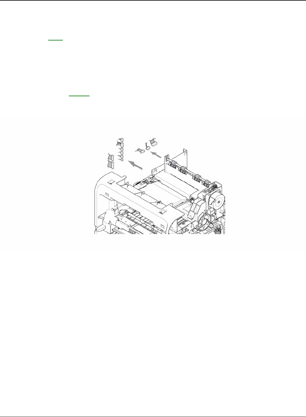
REP 8 Shield Controller Assembly
Parts List on: PL 1
WARNING
Switch off the electricity to the machine. Disconnect the power cord from the customer supply
while performing tasks that do not need electricity. Electricity can cause death or injury. Moving
parts can cause injury.
1. Before removing the Shield Controller Assembly, remove the:
- Side Cover Left, REP 7.
2. Unplug the all connectors from the Main PBA.
Figure 1
Repairs and Adjustments
4-26 5/08 Phaser 3435
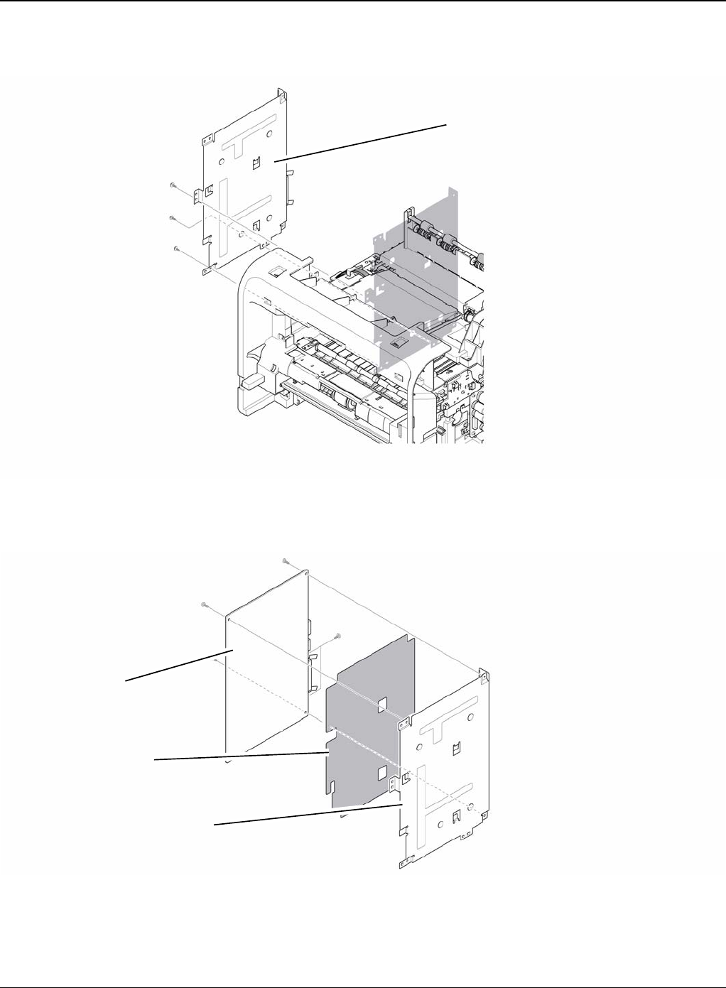
3. Remove the three screws securing the Shield Controller Assembly and remove it.
Figure 2
4. Remove the five screws securing the Main PBA to the Shield and remove it.
Figure 3
Shield controller assembly
Insulator sheet
Shield
Main PBA
Repairs and Adjustments
Phaser 3435 5/08 4-27
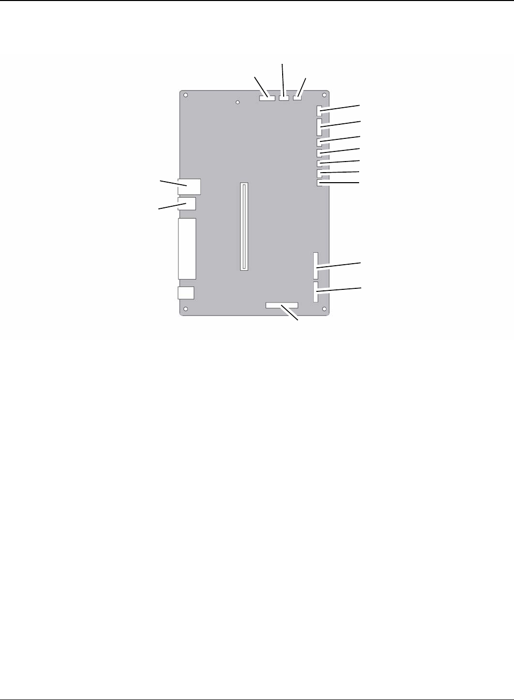
5. The connectors are located, as shown below.
Figure 4
LED OPE
LCD OPE
Cartridge
LSU
Thermistor
MPF SEN
MPF
REGI
Pick up
LSU S/W
BLDC
Duplex
USB
Line
Engine
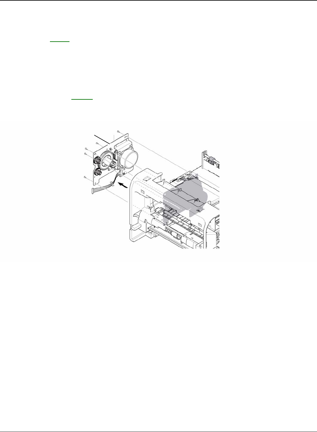
Repairs and Adjustments
4-28 5/08 Phaser 3435
REP 9 Drive Assembly
Parts List on: PL 10
WARNING
Switch off the electricity to the machine. Disconnect the power cord from the customer supply
while performing tasks that do not need electricity. Electricity can cause death or injury. Moving
parts can cause injury.
1. Before removing the Drive Assembly, remove the:
- Side Cover Left, REP 7.
2. Remove the six screws securing the Drive Assembly and remove it.
Figure 1
Note: The six screws have numbers stamped into the Drive Assembly base plate. When refitting
the Drive Assembly tighten the screws the order they are numbered. Only screws numbered 1 to
5 are fitted at this stage. Screw 6 is fitted when the Shield Controller Assembly is refitted.
Drive assembly
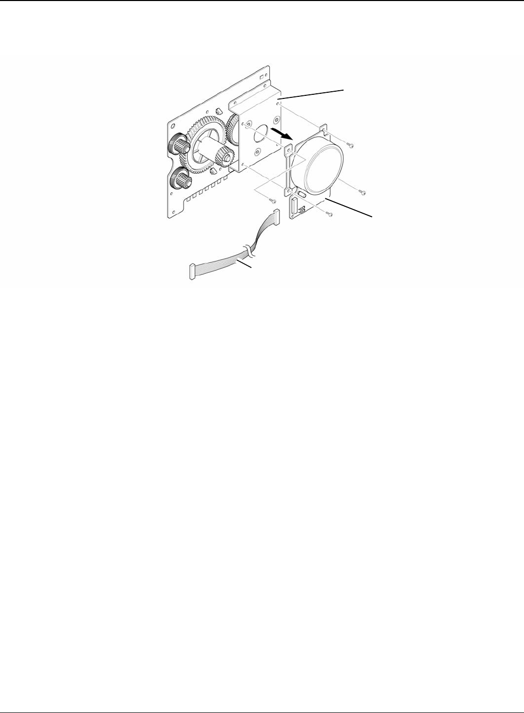
Repairs and Adjustments
Phaser 3435 5/08 4-29
3. If necessary, remove the four screws securing the BLDC Motor Assembly and remove it.
Figure 2
Gear bracket assembly
Harness
BLDC motor assembly
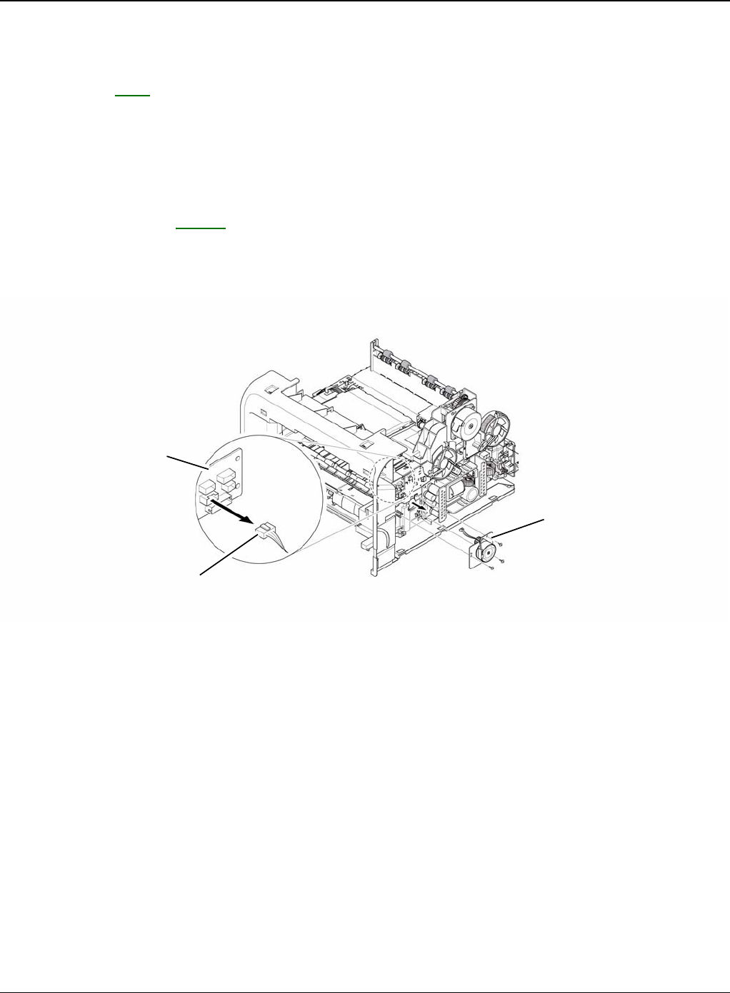
Repairs and Adjustments
4-30 5/08 Phaser 3435
REP 10 Duplex Drive Assembly
Parts List on: PL 1
WARNING
Switch off the electricity to the machine. Disconnect the power cord from the customer supply
while performing tasks that do not need electricity. Electricity can cause death or injury. Moving
parts can cause injury.
1. Before removing the Duplex Drive Assembly, remove the:
- Side Cover Right, REP 7.
2. Unplug the connector from the Connection PCB and remove the three screws securing the
Duplex Drive Unit and remove it.
Figure 1
Connection PCB
Duplex motor
Duplex drive assembly
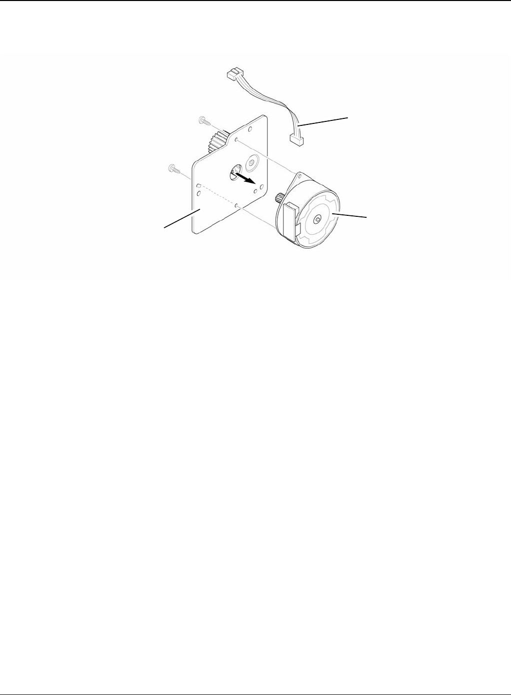
Repairs and Adjustments
Phaser 3435 5/08 4-31
3. If necessary, remove the two screws securing the Duplex Motor and remove it.
Figure 2
Harness
Bracket assembly
Duplex motor
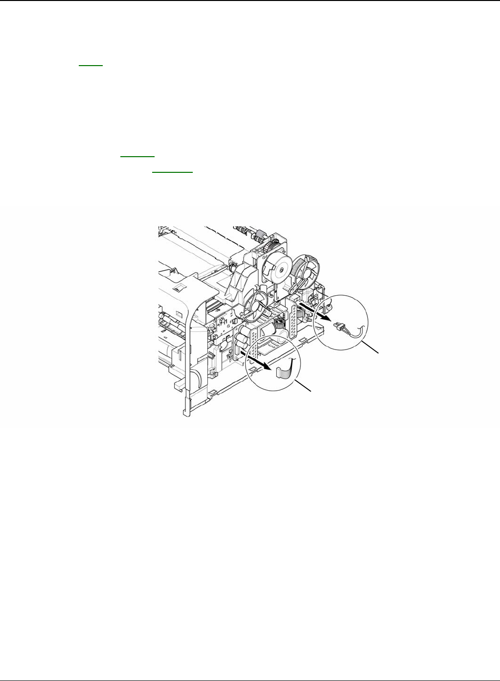
Repairs and Adjustments
4-32 5/08 Phaser 3435
REP 11 Shield SMPS Assembly
Parts List on: PL 1
WARNING
Switch off the electricity to the machine. Disconnect the power cord from the customer supply
while performing tasks that do not need electricity. Electricity can cause death or injury. Moving
parts can cause injury.
1. Before removing the Shield SMPS Assembly, remove the:
- Side Cover Right, REP 7.
- Duplex Drive Assembly, REP 10.
2. Unplug the two connectors (HVPS, Fuser).
Figure 1
Fuser connector
HVPS connector
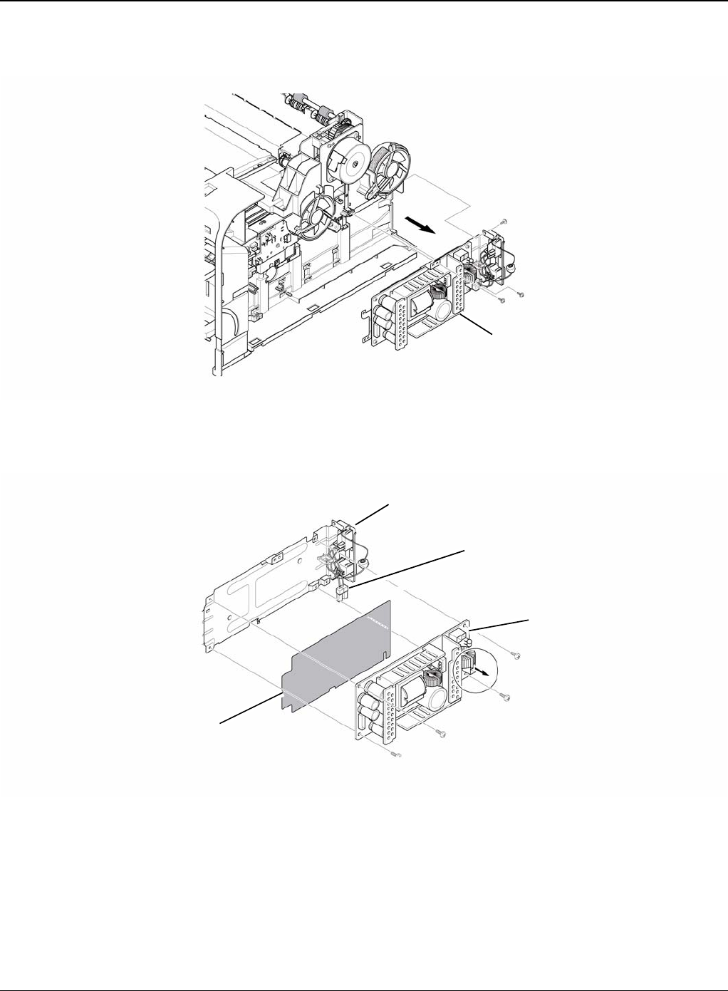
Repairs and Adjustments
Phaser 3435 5/08 4-33
3. Remove the three screws securing the Shield SMPS Assembly and remove it.
Figure 2
4. Unplug the connector (AC Inlet) and remove the four screws securing SMPS and remove it.
Figure 3
Shield SMPS assembly
AC inlet connector
SMPS
Insulator sheet
Shield SMPS (with AC inlet)
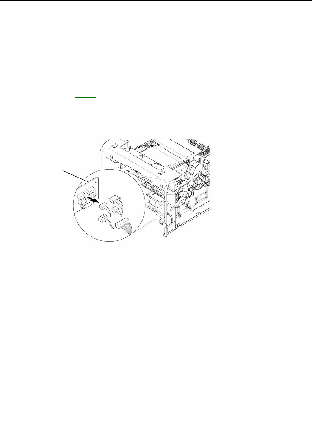
Repairs and Adjustments
4-34 5/08 Phaser 3435
REP 12 Connection PCB
Parts List on: PL 8
WARNING
Switch off the electricity to the machine. Disconnect the power cord from the customer supply
while performing tasks that do not need electricity. Electricity can cause death or injury. Moving
parts can cause injury.
1. Before removing the Connection PCB, remove the:
- Side Cover Right, REP 7.
2. Unplug the all connectors.
Figure 1
Connection PCB
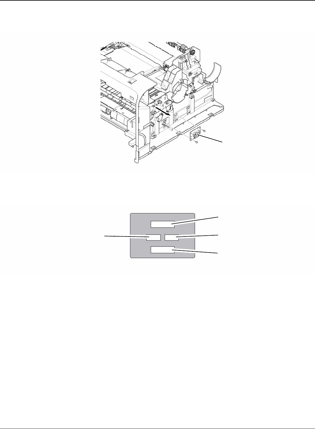
Repairs and Adjustments
Phaser 3435 5/08 4-35
3. Remove the two screws securing the Connection PCB and remove it.
Figure 2
4. The connectors are located, as shown below.
Figure 3
Connection PCB
HVPS
FAN duplex exit motor
Duplex motor Fan main
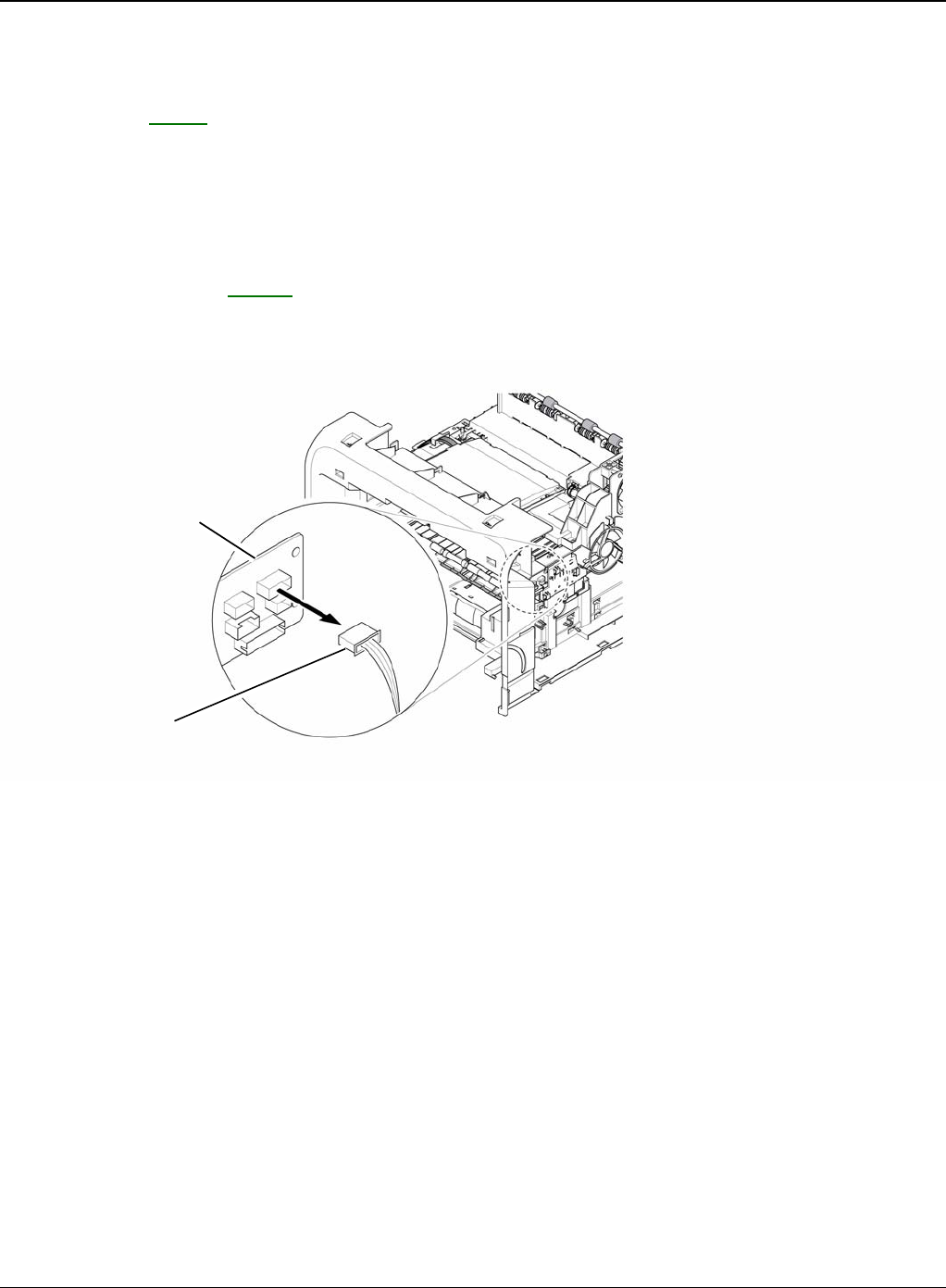
Repairs and Adjustments
4-36 5/08 Phaser 3435
REP 13 Fuser Drive Assembly
Parts List on: PL 13
WARNING
Switch off the electricity to the machine. Disconnect the power cord from the customer supply
while performing tasks that do not need electricity. Electricity can cause death or injury. Moving
parts can cause injury.
1. Before removing the Fuser Drive Assembly, remove the:
- Side Cover Right, REP 7.
2. Unplug the connector from the Connection PCB.
Figure 1
Connection PCB
Fuser drive
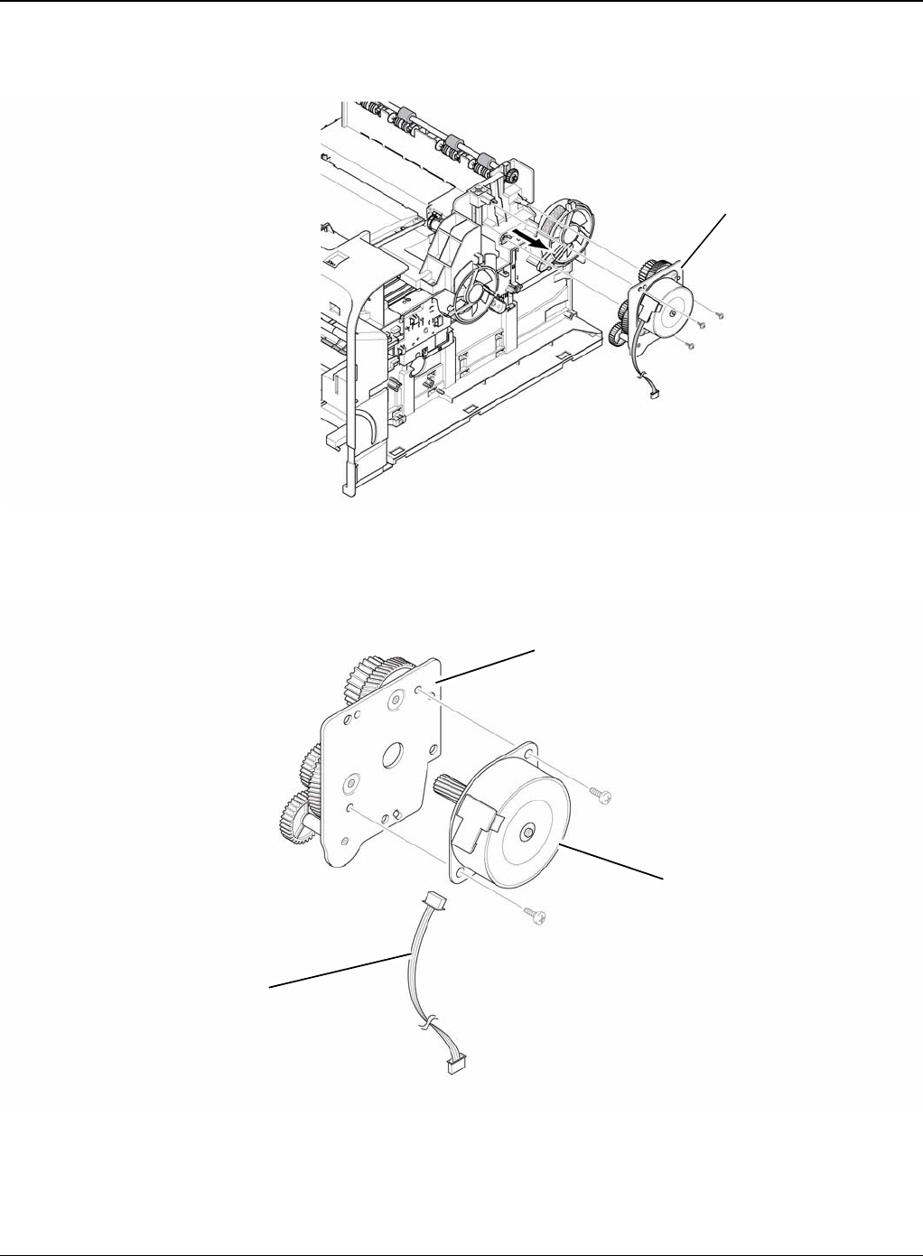
Repairs and Adjustments
Phaser 3435 5/08 4-37
3. Remove the three screws securing the Fuser Drive Assembly and remove it.
Figure 2
4. If necessary, remove the two screws securing the Step Motor and remove it.
Figure 3
Fuser drive assembly
Step motor
Harness
Fuser exit bracket assembly
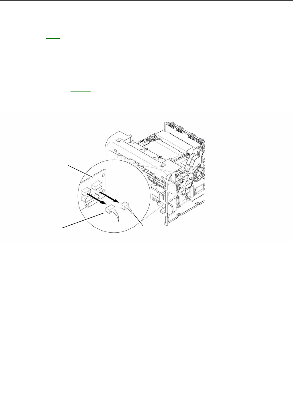
Repairs and Adjustments
4-38 5/08 Phaser 3435
REP 14 Fans
Parts List on: PL 1
WARNING
Switch off the electricity to the machine. Disconnect the power cord from the customer supply
while performing tasks that do not need electricity. Electricity can cause death or injury. Moving
parts can cause injury.
1. Before removing the Fan, remove the:
- Side Cover Right, REP 7.
2. Unplug the two connectors from the Connection PCB, as shown below.
Figure 1
Connection PCB
Main fan Duplex fan
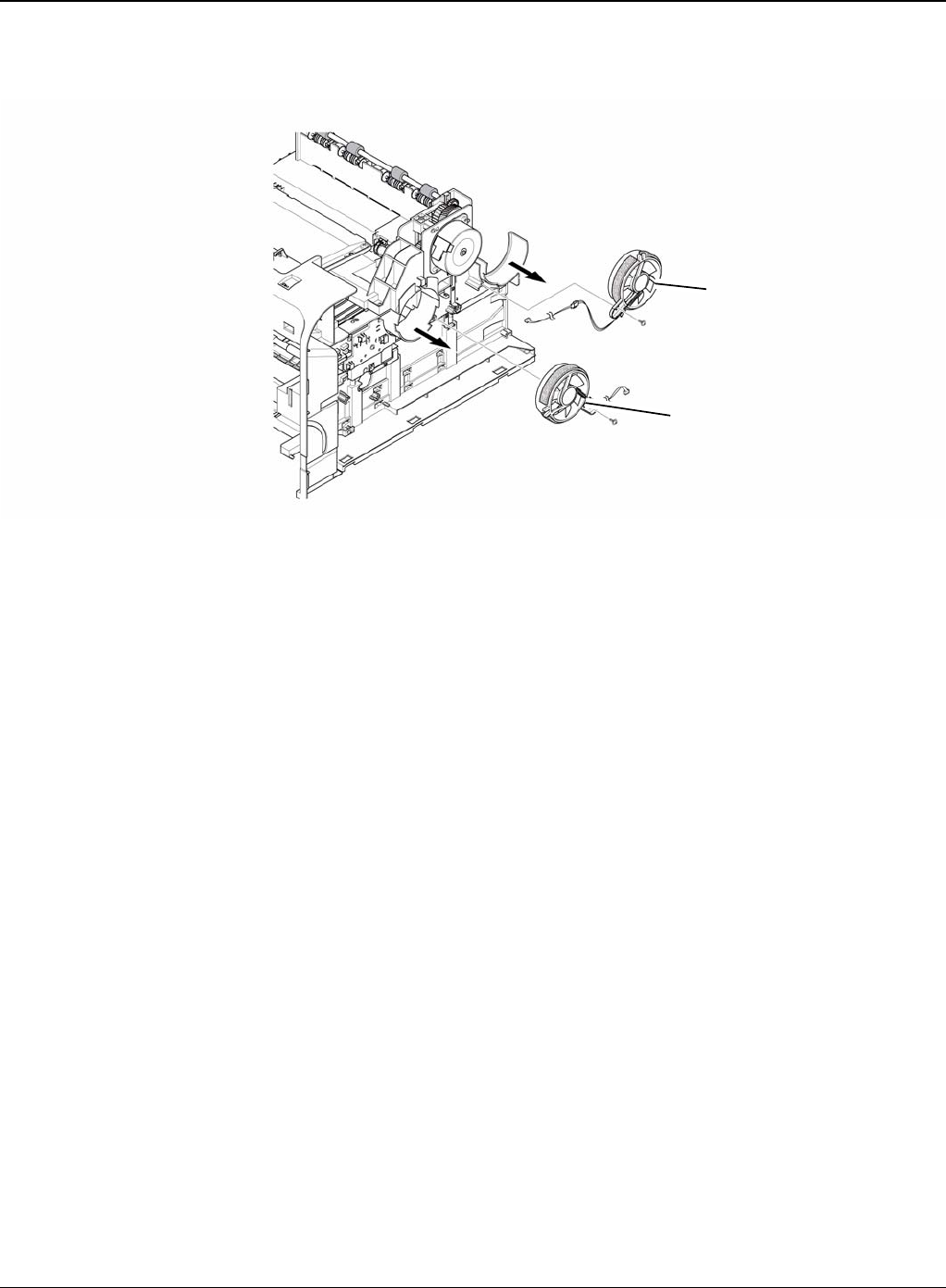
Repairs and Adjustments
Phaser 3435 5/08 4-39
3. Remove the two screws securing the Fans and then pull the Fans (Main, Duplex).
Figure 2
Duplex fan
Main fan
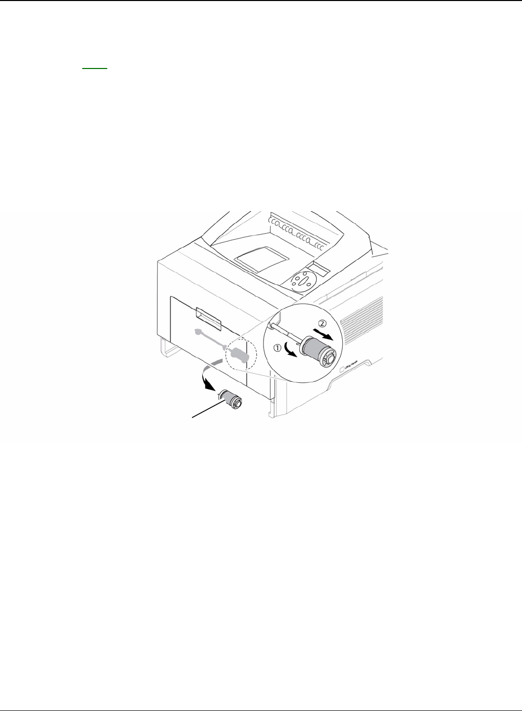
Repairs and Adjustments
4-40 5/08 Phaser 3435
REP 15 Pick-up Roller Assembly
Parts List on: PL 6
WARNING
Switch off the electricity to the machine. Disconnect the power cord from the customer supply
while performing tasks that do not need electricity. Electricity can cause death or injury. Moving
parts can cause injury.
1. Take out the Cassette.
2. To remove the Pick Up Roller Assembly, first lift the notch attached to the Pick Up Roller
Assembly from the Shaft, then slide the Pick Up Roller Assembly from left to right and it will
be released completely, as shown below.
Figure 1
3. To remove the Shaft, first release the locker and slide the Shaft from left to right, then lift the
notch attached to the Cam so that it's released from the Shaft. Then release the Bush from
the Shaft and remove the Shaft from the Duplex Guide Housing, as shown in Figure 2.
Pick up roller assembly
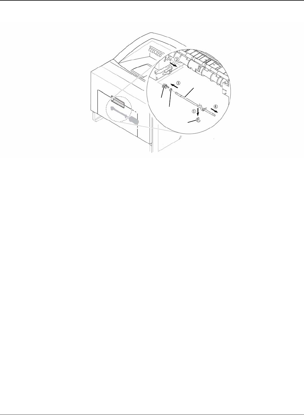
Repairs and Adjustments
Phaser 3435 5/08 4-41
Figure 2
Cam
Bush
Locker
Shaft
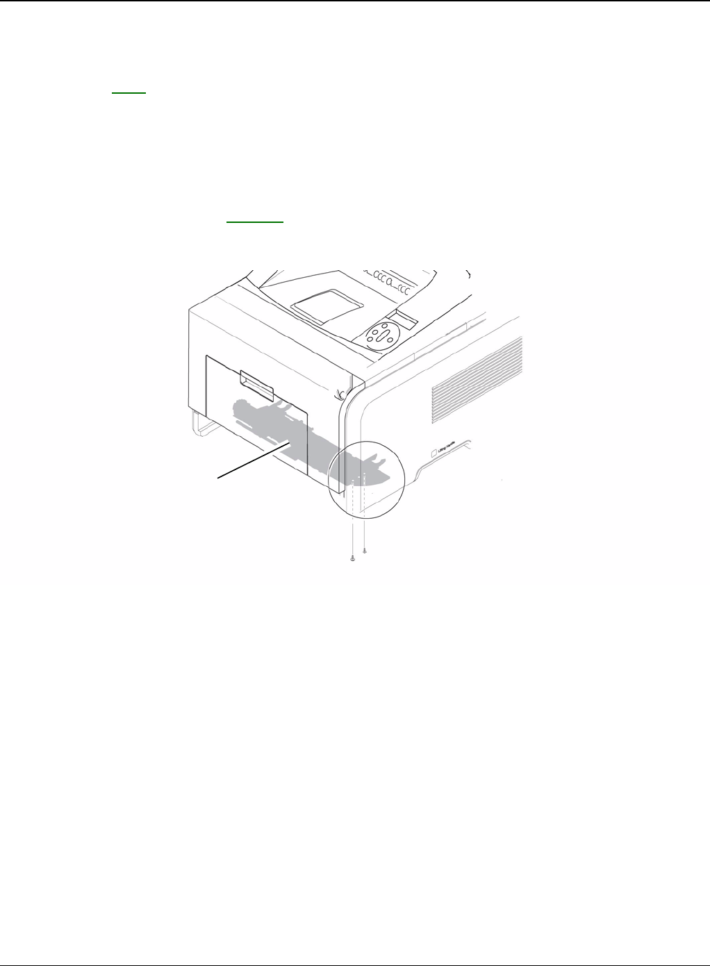
Repairs and Adjustments
4-42 5/08 Phaser 3435
REP 16 Duplex Guide Housing (With Feed Roller)
Parts List on: PL 6
WARNING
Switch off the electricity to the machine. Disconnect the power cord from the customer supply
while performing tasks that do not need electricity. Electricity can cause death or injury. Moving
parts can cause injury.
1. Before removing the Duplex Guide Housing, remove the:
- Pick Up Roller Assembly, REP 15.
2. Remove the two screws securing the Duplex Guide Housing.
Figure 1
Duplex guide housing
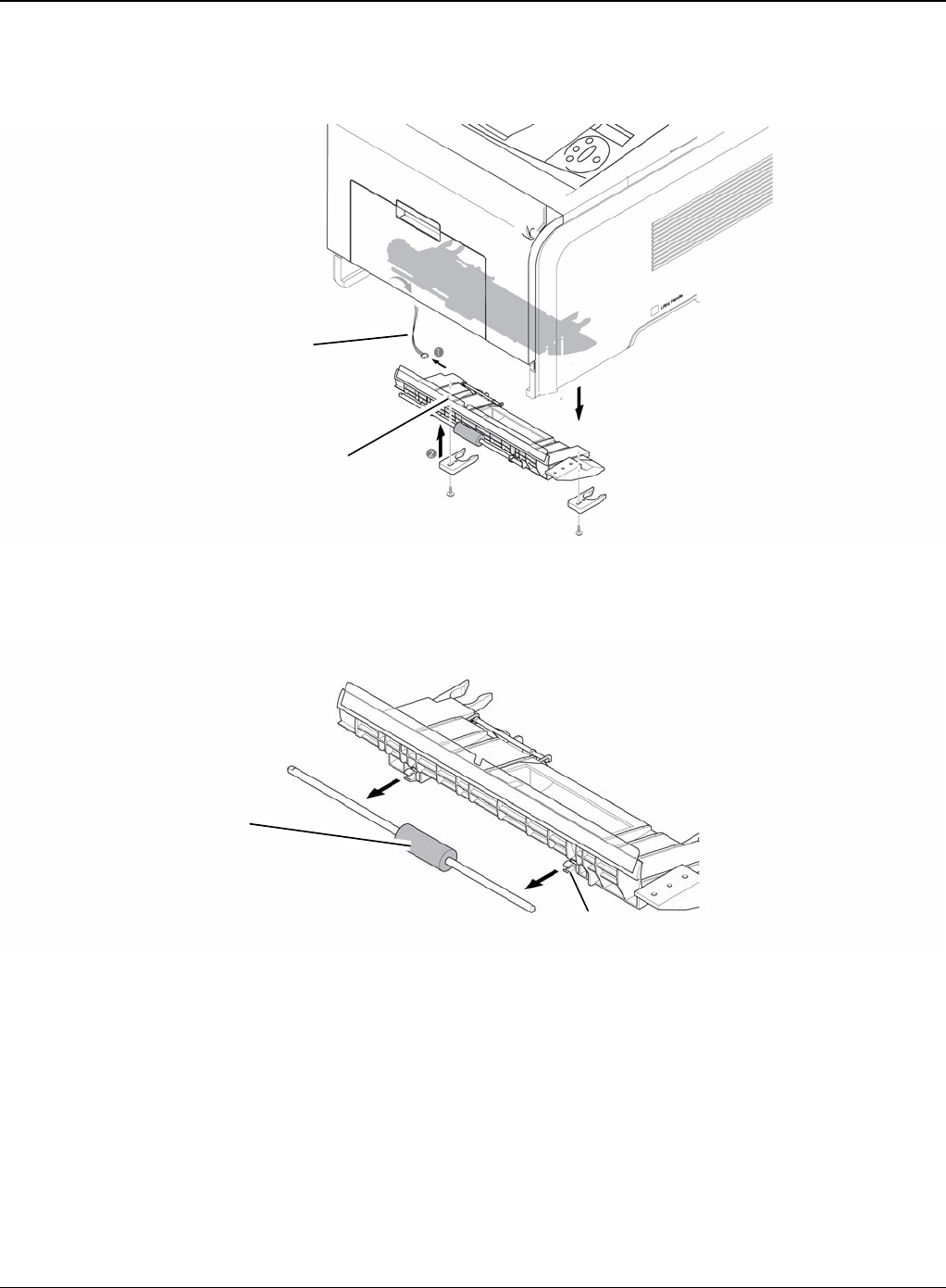
Repairs and Adjustments
Phaser 3435 5/08 4-43
3. Unplug the one connector (Photo Interrupter) and remove the Duplex Guide Housing (with
Feed Roller), as shown below.
Figure 2
4. Pull the Feed Roller from the Bushing.
Figure 3
Photo interrupter connector
Duplex guide housing
Feed roller
Bushing
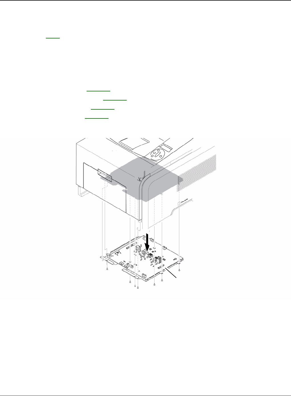
Repairs and Adjustments
4-44 5/08 Phaser 3435
REP 17 HVPS Housing
Parts List on: PL 6
WARNING
Switch off the electricity to the machine. Disconnect the power cord from the customer supply
while performing tasks that do not need electricity. Electricity can cause death or injury. Moving
parts can cause injury.
1. Before removing the HVPS Housing, remove the:
-Duplex Drive Assembly, REP 10.
-Unplug the HVPS Connector, REP 11.
-Pick Up Roller Assembly, REP 15.
-Duplex Guide Housing, REP 16.
2. Remove the eight screws securing the HVPS Housing, as shown below.
Figure 1
HVPS housing
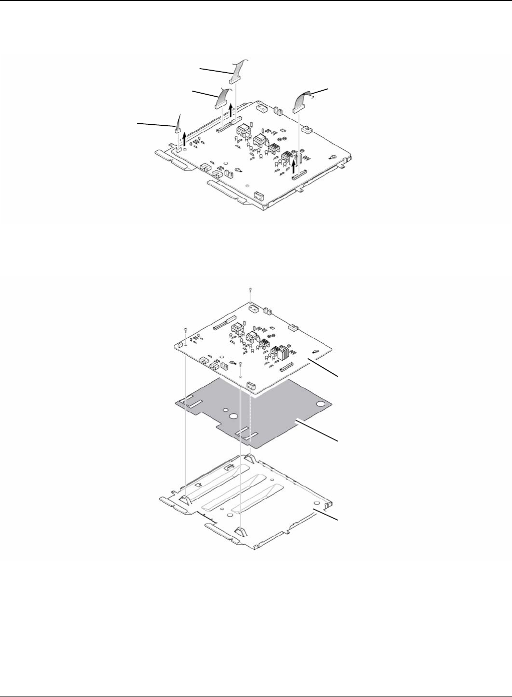
Repairs and Adjustments
Phaser 3435 5/08 4-45
3. Unplug the connector for connector PBA and SMPS first. Unplug the other Connections.
Figure 2
4. If necessary, remove the three screws securing the HVPS and remove it.
Figure 3
Duplex motor
Duplex guide housing
Engine Connection PBA & SMPS
HVPS
Insulator sheet
Shield
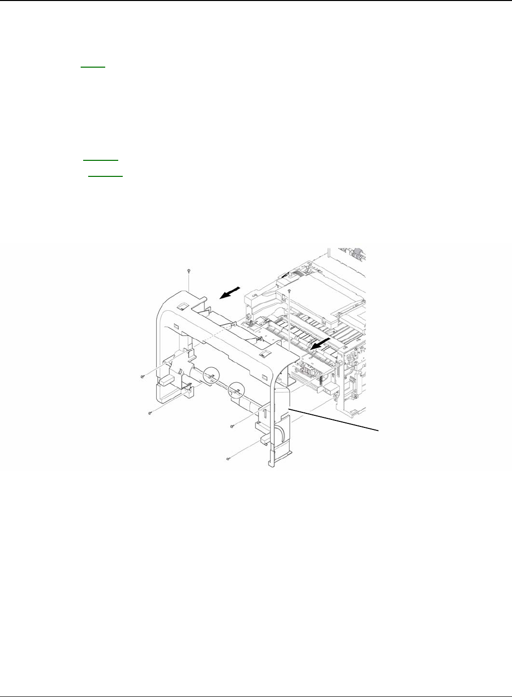
Repairs and Adjustments
4-46 5/08 Phaser 3435
REP 18 Cover Mid Front
Parts List on: PL 2
WARNING
Switch off the electricity to the machine. Disconnect the power cord from the customer supply
while performing tasks that do not need electricity. Electricity can cause death or injury. Moving
parts can cause injury.
1. Before removing the Cover Mid Front, remove the:
-Top Cover, REP 5.
-Side Cover, REP 7.
2. Remove the six screws securing the Cover Mid Front and release two hooks in the centre.
CAUTION
This cover is fragile take care when removing it
Figure 1
Cover mid front
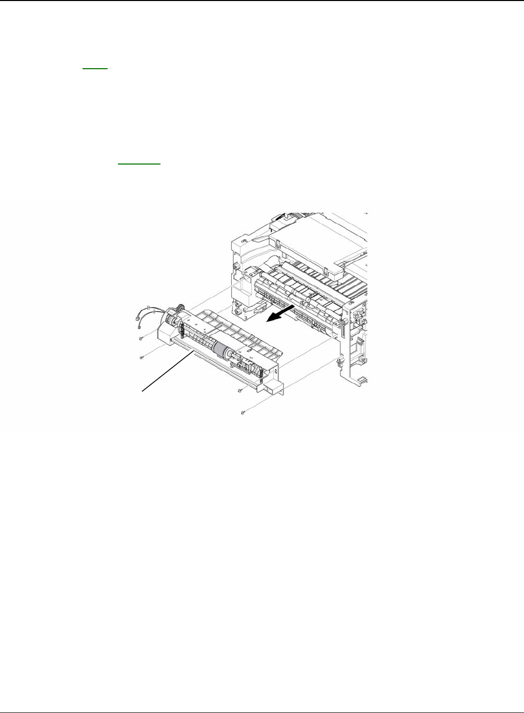
Repairs and Adjustments
Phaser 3435 5/08 4-47
REP 19 MPF Housing
Parts List on: PL 9
WARNING
Switch off the electricity to the machine. Disconnect the power cord from the customer supply
while performing tasks that do not need electricity. Electricity can cause death or injury. Moving
parts can cause injury.
1. Before removing the MPF Housing, remove the:
-Cover Mid Front, REP 18.
2. Remove the four screws securing the MPF Housing and remove it.
Figure 1
MFP housing
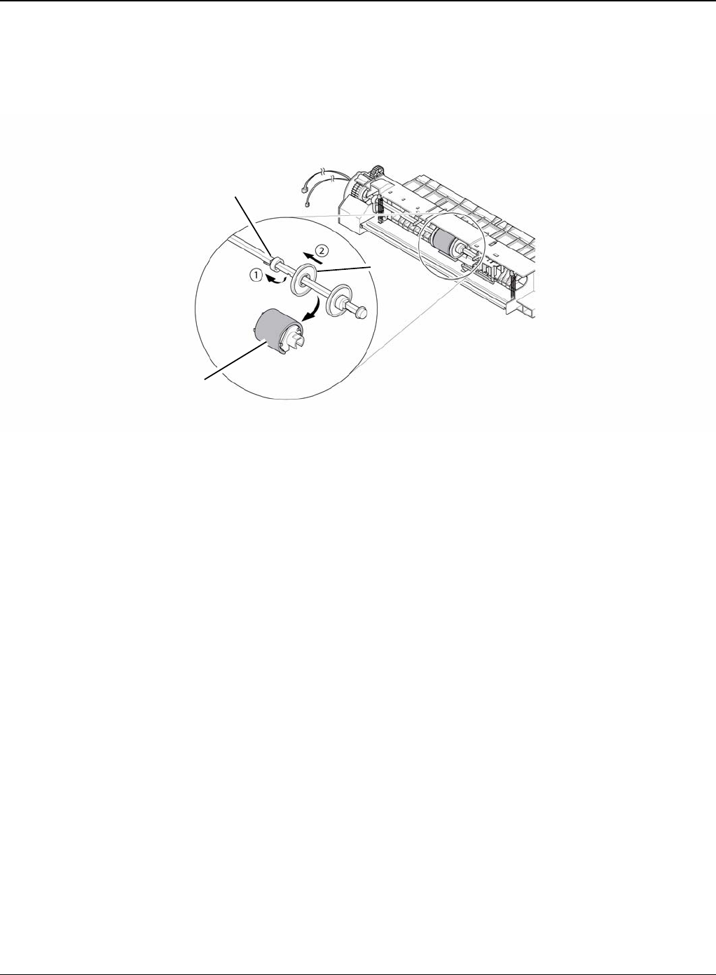
Repairs and Adjustments
4-48 5/08 Phaser 3435
3. To remove the MP Pick Up Assembly, first lift the notch attached to the left side Stopper so
that it's slide the right to left from the Shaft, then left side Idler slid the right to left from the
Shaft and take out the MP Pick Up Assembly, as shown below.
Figure 2
Idler
Stopper
MP pick up assembly
MPF housing
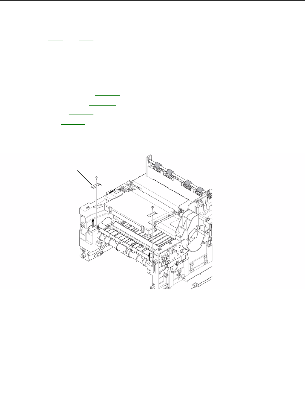
Repairs and Adjustments
Phaser 3435 5/08 4-49
REP 20 Feed Roller Parts
Parts List on: PL 6 and PL 7
WARNING
Switch off the electricity to the machine. Disconnect the power cord from the customer supply
while performing tasks that do not need electricity. Electricity can cause death or injury. Moving
parts can cause injury.
1. Before removing the Feed Roller Parts, remove the:
-Pick Up Roller Assembly, REP 15.
-Duplex Guide Housing, REP 16.
-Cover Mid Front, REP 18.
-MPF Housing, REP 19.
2. Remove the two screws securing the both side of the Guide Paper and then remove the
Guides.
Figure 1
Guide paper
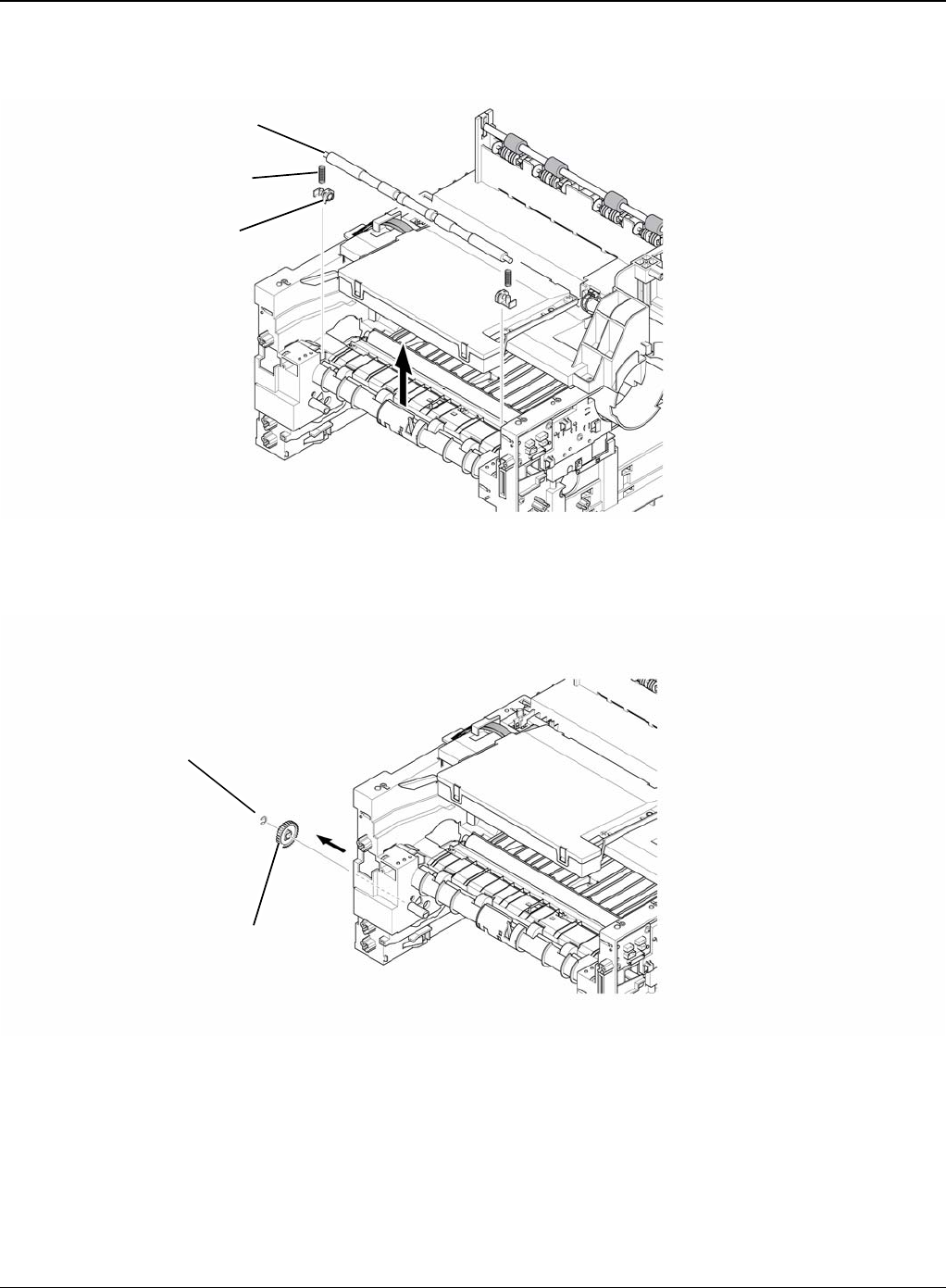
Repairs and Adjustments
4-50 5/08 Phaser 3435
3. Pull up the Feed Idle Shaft and the Bushes (with Spring).
Figure 2
4. Release the E-Ring securing the Feed 2 Gear and remove it.
Figure 3
Feed idle shaft
Spring
Bush
E-ring
Feed 2 gear
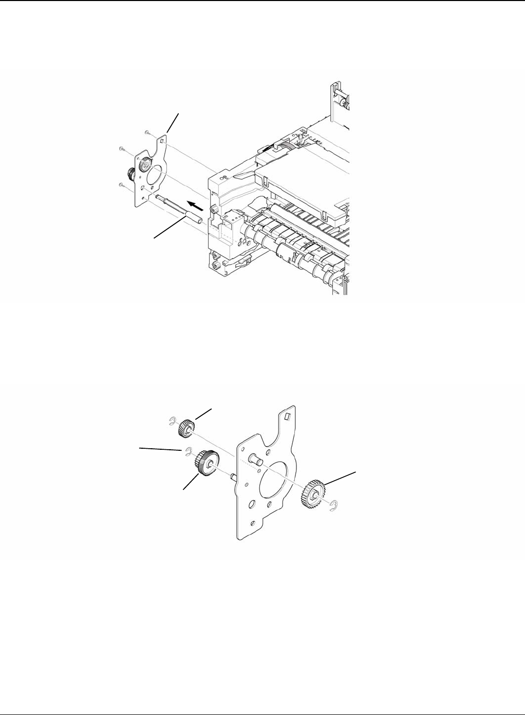
Repairs and Adjustments
Phaser 3435 5/08 4-51
5. Remove the three screws securing the Feed Bracket Unit and then remove the Feed Bracket
Unit and Feed 2 Shaft.
Figure 4
6. If necessary, release the three E-Rings. Pull up the Feed 1 Roller from the Bushing, as the
Gears (T2 Idle, Retard, Idle) and then remove the Gears from the Feed Bracket, as shown
below.
Figure 5
Feed bracket unit
Feed2 shaft
Idle gear
E-ring
Retard gear
T2 idle gear
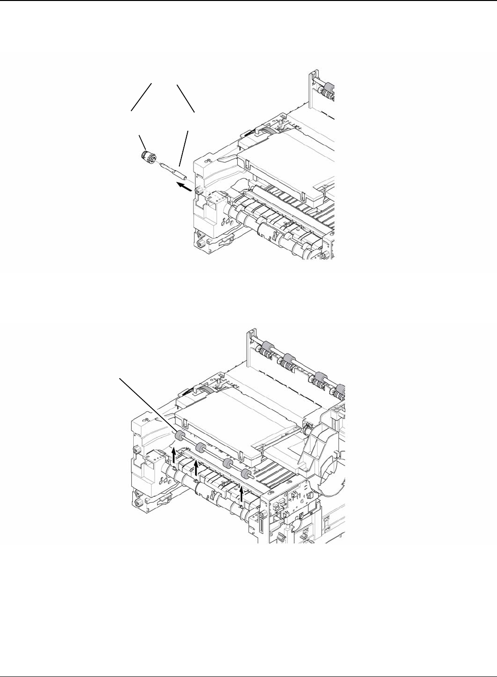
Repairs and Adjustments
4-52 5/08 Phaser 3435
7. Remove the Clutch Unit, as shown below.
Figure 6
8. Pull up the Feed 1 Roller from the Bushing, as shown below.
Figure 7
Clutch unit
Feed shaft
Feed 1 gear
assembly
Feed 1 roller
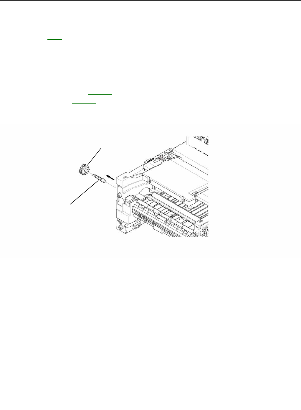
Repairs and Adjustments
Phaser 3435 5/08 4-53
REP 21 Pick Up Gear Assembly & Solenoids
Parts List on: PL 6
WARNING
Switch off the electricity to the machine. Disconnect the power cord from the customer supply
while performing tasks that do not need electricity. Electricity can cause death or injury. Moving
parts can cause injury.
1. Before removing the Pick Up Gear Assembly & Solenoids, remove the:
-Duplex Guide Housing, REP 16.
-Feed Bracket Unit REP 20.
2. Release the Pick Up Gear Assembly and Pick Up Gear Shaft, as shown below.
Figure 1
Pickup gear assembly
Pick up gear shaft
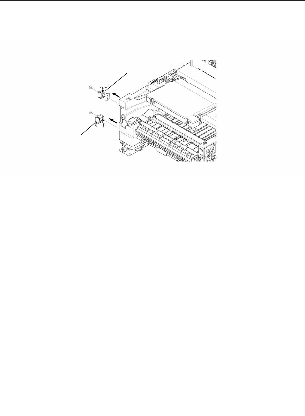
Repairs and Adjustments
4-54 5/08 Phaser 3435
3. Remove the two screws securing the Manual Solenoid and Feed Solenoid and then remove
the Solenoids, as shown below.
Figure 2
Feed solenoid
Manual solenoid
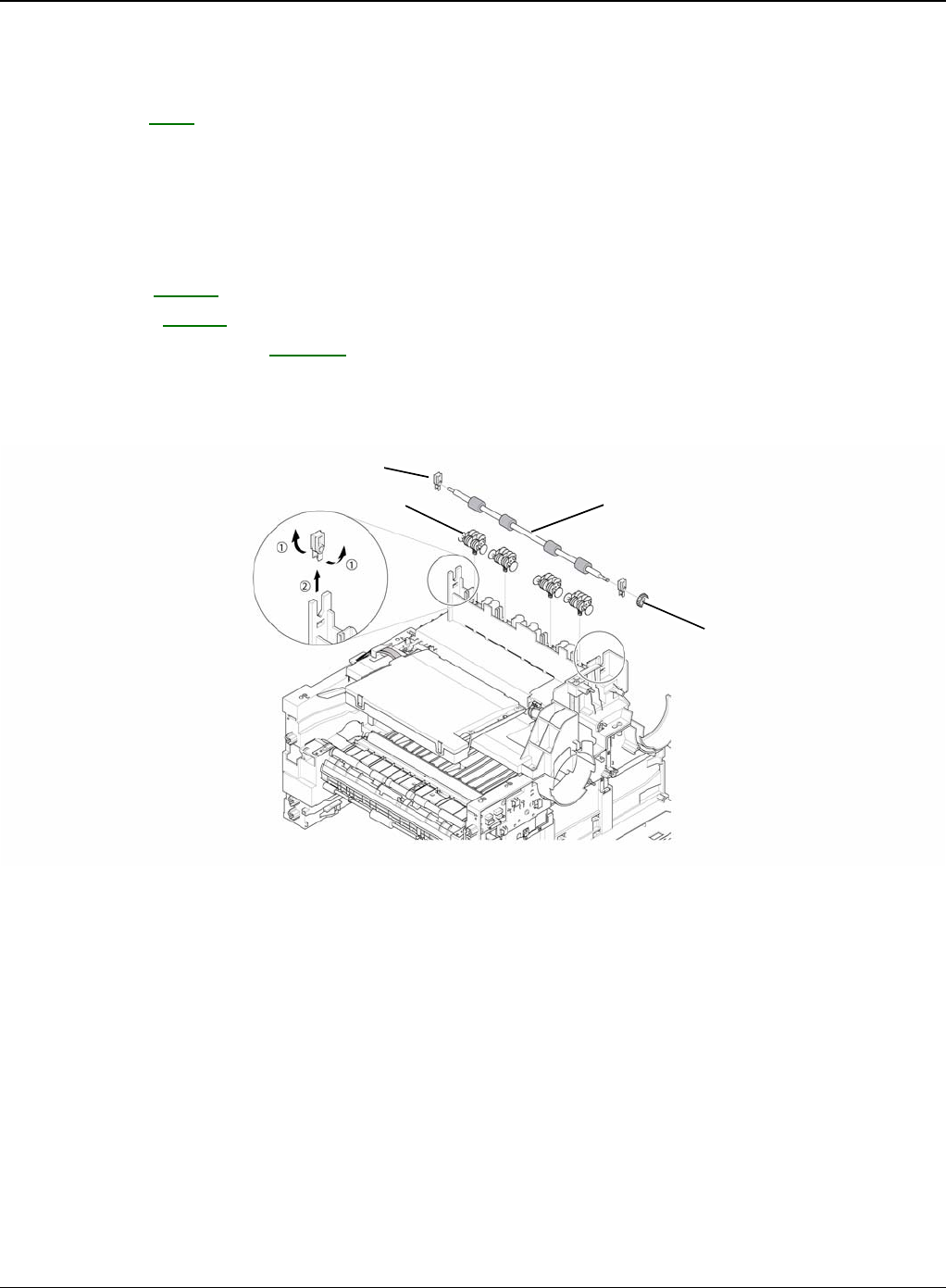
Repairs and Adjustments
Phaser 3435 5/08 4-55
REP 22 Exit Roller
Parts List on: PL 7
WARNING
Switch off the electricity to the machine. Disconnect the power cord from the customer supply
while performing tasks that do not need electricity. Electricity can cause death or injury. Moving
parts can cause injury.
1. Before removing the Exit Roller, you remove the:
-Top Cover, REP 5.
-Side Cover, REP 7.
-Fuser Drive Assembly, REP 13.
2. Remove the Exit Gear, and release the Bearing at one end then remove the Roller Exit F/
Down and Exit Roller Rack, as shown below.
Figure 1
Exit gear
Roller exit F/down
Exit roller rack
Bearing
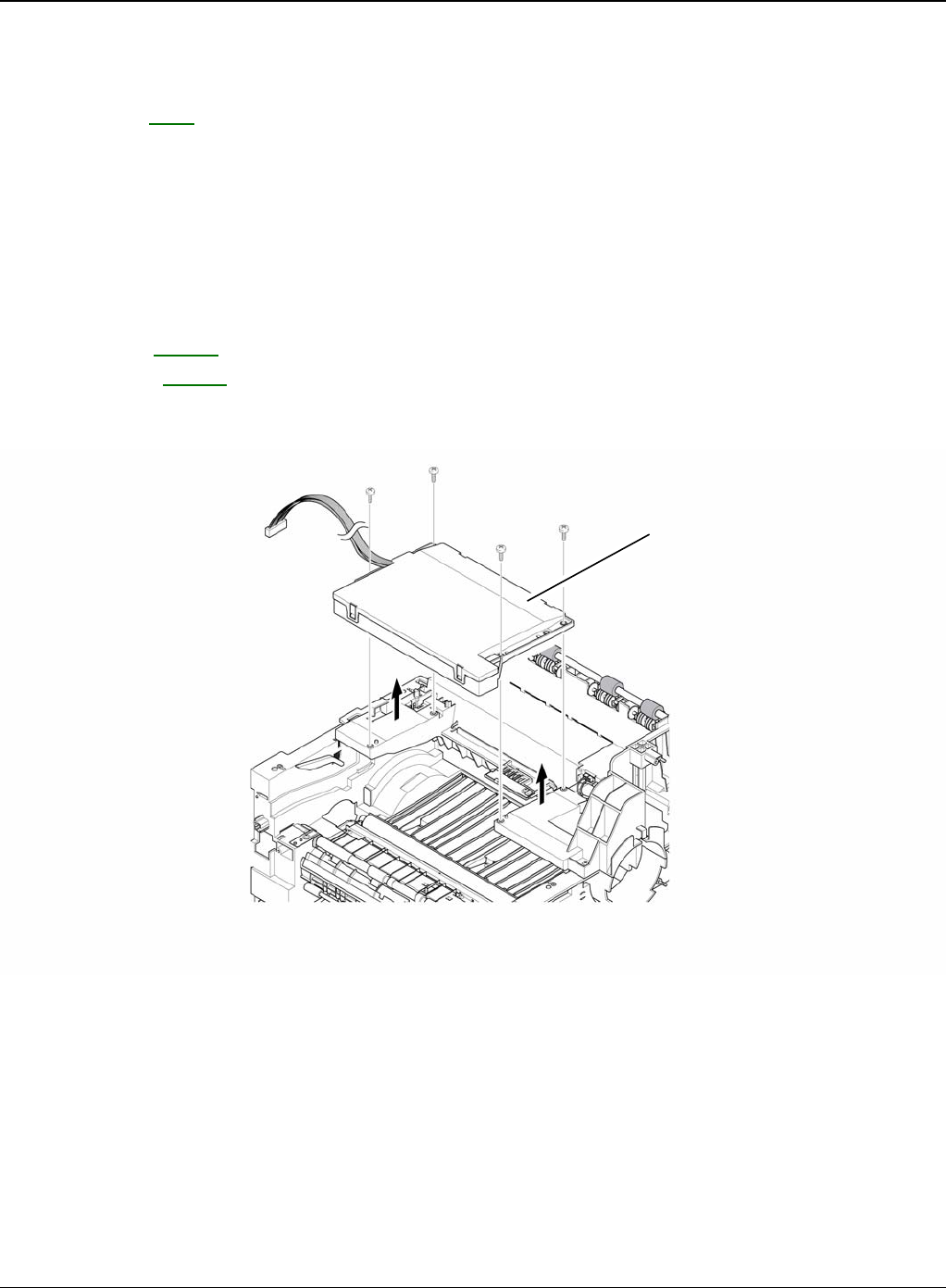
Repairs and Adjustments
4-56 5/08 Phaser 3435
REP 23 LSU
Parts List on: PL 1
WARNING
Switch off the electricity to the machine. Disconnect the power cord from the customer supply
while performing tasks that do not need electricity. Electricity can cause death or injury. Moving
parts can cause injury. WARNING
Avoid exposure to laser beam. Invisible laser radiation.
1. Before removing the LSU, remove the:
-Top Cover, REP 5.
-Side Cover, REP 7.
2. Remove the four screws securing the LSU and remove it.
Figure 1
LSU
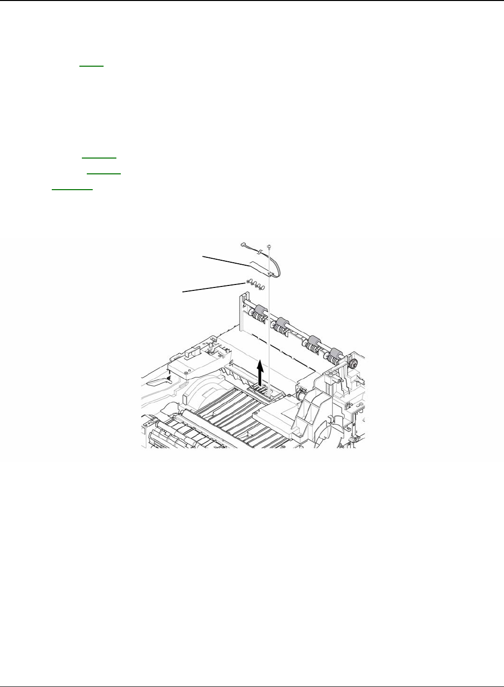
Repairs and Adjustments
Phaser 3435 5/08 4-57
REP 24 Terminal
Parts List on: PL 7
WARNING
Switch off the electricity to the machine. Disconnect the power cord from the customer supply
while performing tasks that do not need electricity. Electricity can cause death or injury. Moving
parts can cause injury.
1. Before removing the CRUM 2 PBA, remove the:
-Top Cover, REP 5.
-Side Cover, REP 7.
-LSU, REP 23.
2. Remove the one screw securing the CRUM 2 PBA and remove it and then release the four
Terminals, as shown below.
Figure 1
Note: Be aware of the Terminals to ensure they are not lost.
3-28
CRUM2 PBA
Terminal
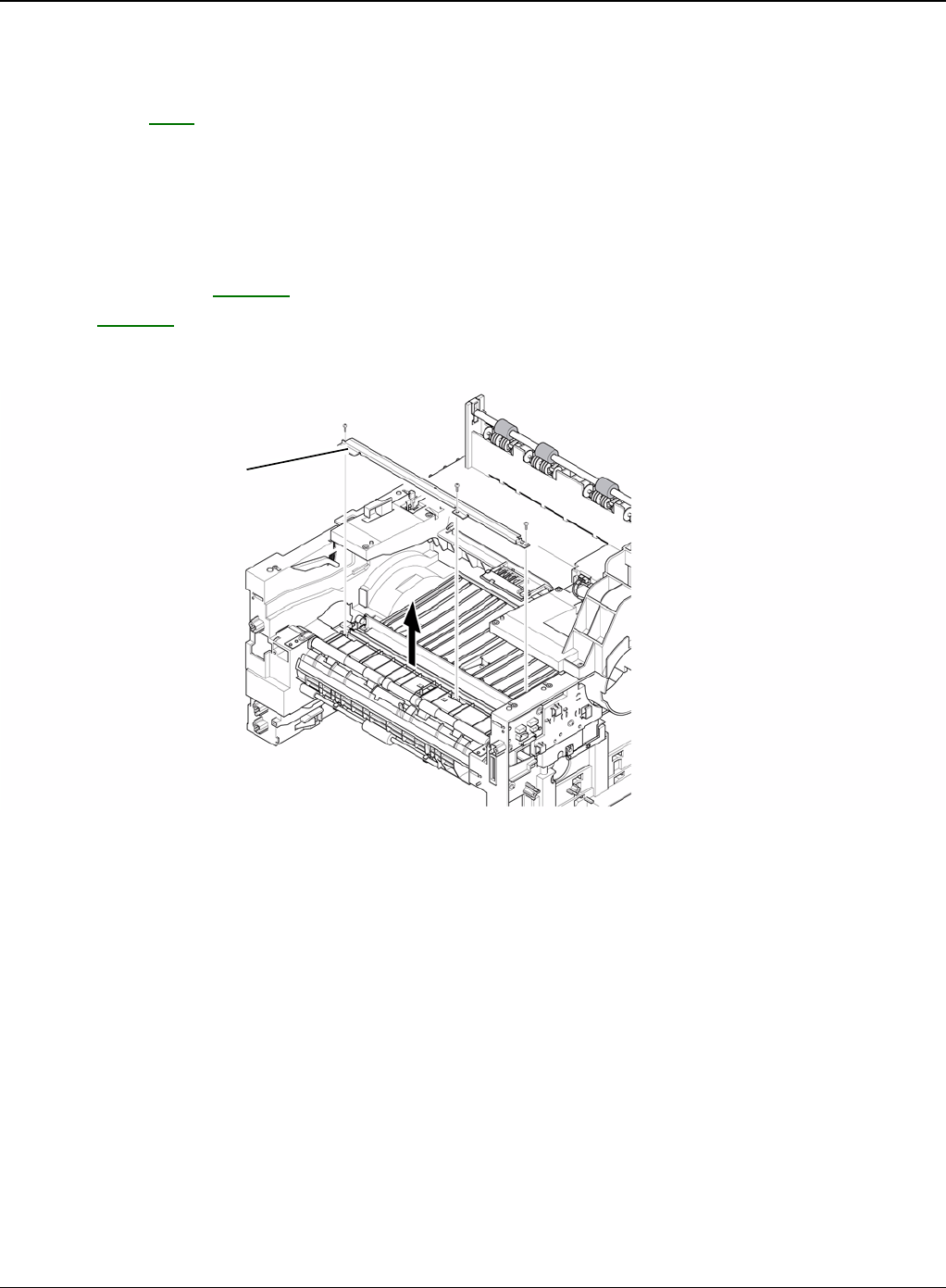
Repairs and Adjustments
4-58 5/08 Phaser 3435
REP 25 Transfer Roller Parts
Parts List on: PL 8
WARNING
Switch off the electricity to the machine. Disconnect the power cord from the customer supply
while performing tasks that do not need electricity. Electricity can cause death or injury. Moving
parts can cause injury.
1. Before removing the Transfer Roller Parts, remove the:
-Cover Mid Front, REP 18.
-LSU, REP 23.
2. Remove the three screws securing the Transfer Earth and remove it.
Figure 1
Transfer earth
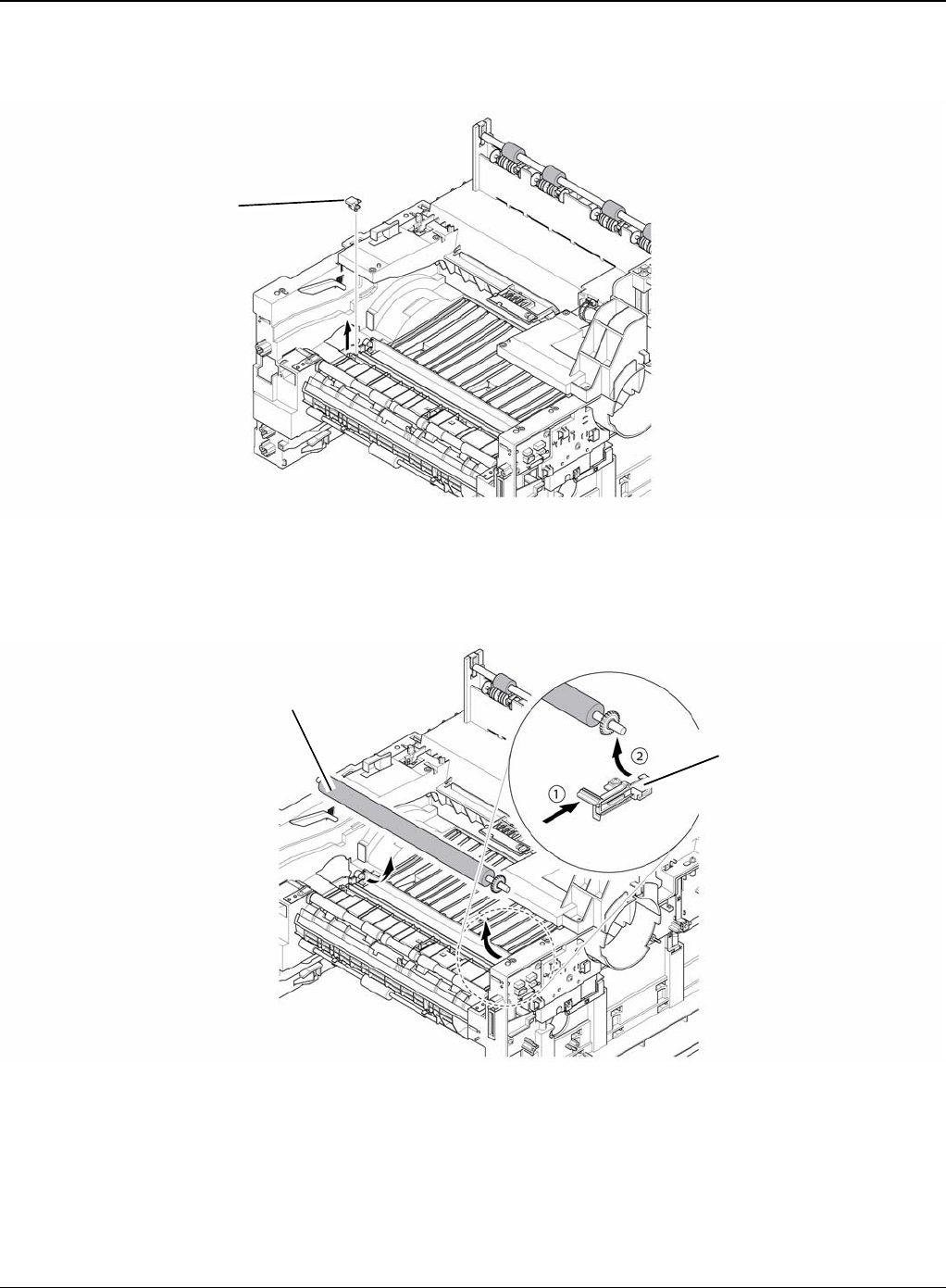
Repairs and Adjustments
Phaser 3435 5/08 4-59
3. Release the PTL Holder, as shown below.
Figure 2
4. To remove the Transfer Roller, first pull the TR Holder and then take out the Transfer Roller,
as shown below.
Figure 3
Note: Do not grab the rubber part of the Transfer Roller, it may cause a malfunction due to a
foreign object. HolD the both side of the Transfer Roller when replacing it.
PTL holder
Transfer roller
TR holder

Repairs and Adjustments
4-60 5/08 Phaser 3435
This page is intentionally blank

Parts List
5-1 5/08 Phaser 3435
5 Parts List
PL 1 Main Parts List ................................................................................................................. 5-2
PL 2 Cover Assembly .............................................................................................................. 5-4
PL 3 Front Cover Assembly .................................................................................................... 5-6
PL 4 Rear Cover Assembly ...................................................................................................... 5-8
PL 5 OPE Cover Assembly .................................................................................................... 5-10
PL 6 Frame (1 of 3) ................................................................................................................ 5-12
PL 7 Frame (2 of 3) ................................................................................................................ 5-14
PL 8 Frame (3 of 3) ................................................................................................................ 5-16
PL 9 MP Assembly ................................................................................................................. 5-18
PL 10 Main Drive Assembly .................................................................................................. 5-20
PL 11 Fuser Drive Assembly .................................................................................................. 5-22
PL 12 Duplex Unit (Optional) ................................................................................................. 5-24
PL 13 Fuser Unit (1 of 2) ........................................................................................................ 5-26
PL 14 Fuser Unit (2 of 2) ........................................................................................................ 5-28
PL 15 Cassette Unit ............................................................................................................... 5-30
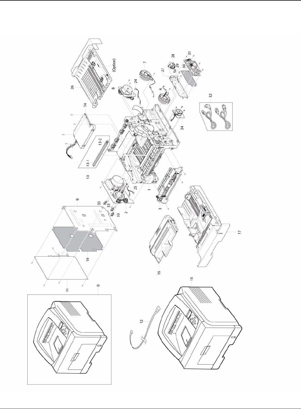
Parts List
5-2 5/08 Phaser 3435
PL 1 Main Parts List

Parts List
Phaser 3435 5/08 5-3
PL 1 Main Parts List
No. Part No. Description QT’y Remark
5.1-0 - MACHINE
5.1-1 - ELA HOU-FRAME 220V 1
5.1-1 - ELA HOU-FRAME 110V 1
5.1-2 007N01561 ELA UNIT-MAIN DRIVE 1
5.1-3 002N02783 ELA HOU-MPF 1
5.1-6 127N07328 FAN-DC 1 REP 14
5.1-7 127N07485 FAN-DC 1 REP 14
5.1-8 - ELA UNIT-FUSER DRIVE 1
5.1-9 - MEA-SHIELD CONTROLLER 1 REP 8
5.1-10 - SHEET-INSULATOR_PBA 1 REP 8
5.1-11 140N63345 PBA MAIN-CONTROLLER 1 REP 8
5.1-12 - CBF HARNESS-LCD_OPE 1
5.1-13 002N02628 MEA-TRANSFER ROLLER 1
5.1-13-1 - ROLLER-TRANSFER 1
5.1-13-2 - GEAR-TRANSFER 1
5.1-14 122N00259 UNIT-LSU 1 REP 23
5.1-15 - MEA-COVER 1
5.1-16 - ELA UNIT-INITIAL DEVE (CARTRIDGE-PRINT) 1
5.1-17 050N00535 MEA UNIT-CASSETTE 1
5.1-24 - CBF HARNESS-EXIT MTR 1
5.1-25 - CBF HARNESS-MAIN MTR 1
5.1-26 101N01422 MEA UNIT-DUPLEX 1
5.1-27 - SHIELD-P-SMPS 1 REP 11
5.1-28 - CBF HARNESS-AC INLET 1
5.1-29 - CABLE CLAMP 3
5.1-30 - SHEET-INSULATOR_SMPS 1 REP 11
5.1-31 112N00229 SMPS (220V) 1 REP 11
5.1-31 112N00228 SMPS (110V) 1 REP 11
5.1-32 117N01769 CBF-POWER CORD(220V) 1
5.1-32 105N02072 CBF-POWER CORD(110V) 1
5.1-33 - CABLE CLAMP 3
5.1-34 - ELA UNIT-DUPLEX DRIVE 1 REP 10
097N01539 OPTIONAL TRAY (NOT SHOWN) 1
144N00159 OPTIONAL MEMORY (128Mb) (NOT SHOWN) 1
144N00139 OPTIONAL MEMORY (256Mb) (NOT SHOWN) 1
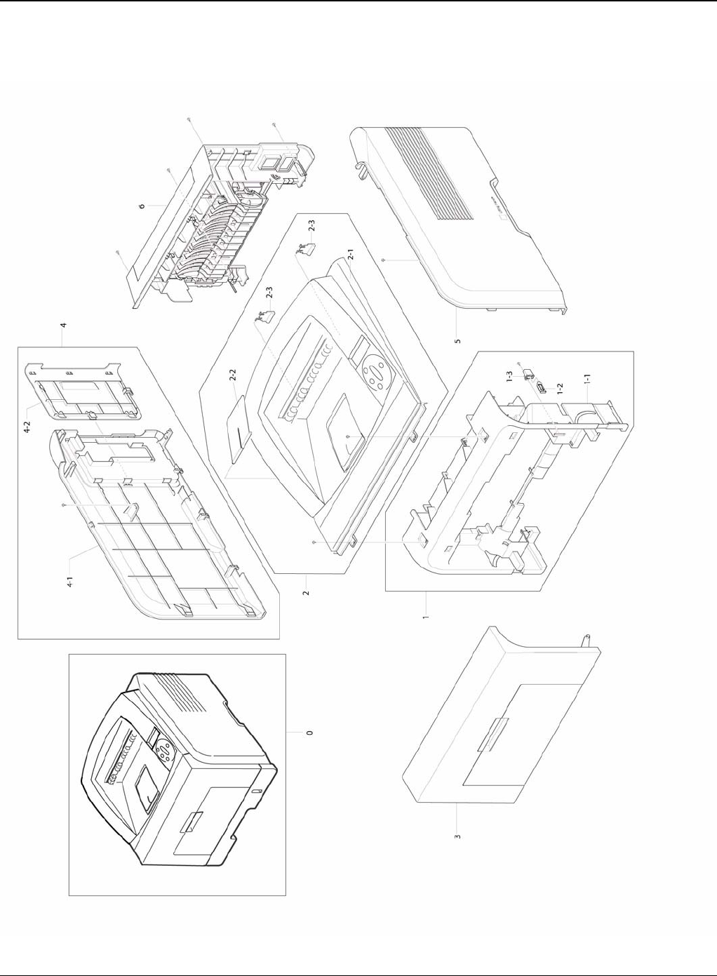
Parts List
5-4 5/08 Phaser 3435
PL 2 Cover Assembly

Parts List
Phaser 3435 5/08 5-5
PL 2 Cover Assembly
No. Part No. Description QT’y Remark
5.2-0 - MEA-COVER 1
5.2-0 - MEA-COVER 1
5.2-1 - MEA-COVER MIDDLE 1 REP 18
5.2-1-1 - COVER-M_MIDDLE 1
5.2-1-2 - PMO-M-SUB ACTUATOR 1
5.2-1-3 - CAP-M_SUB ACTUATOR 1
5.2-2 - MEA-COVER TOP 1 REP 5
5.2-2-1 - COVER-M_TOP 1
5.2-2-2 - PMO-STACKER RX 1
5.2-2-3 - PMO-SUB STACKER 2
5.2-3 - MEA-COVER FRONT 1
5.2-4 - MEA-COVER SIDE L 1 REP 7
5.2-4-1 - COVER-M_SIDE L 1
5.2-4-2 - COVER-M_DIMM 1
5.2-5 - MEA-COVER SIDE R 1 REP 7
5.2-6 - MEA-COVER REAR 1 REP 3
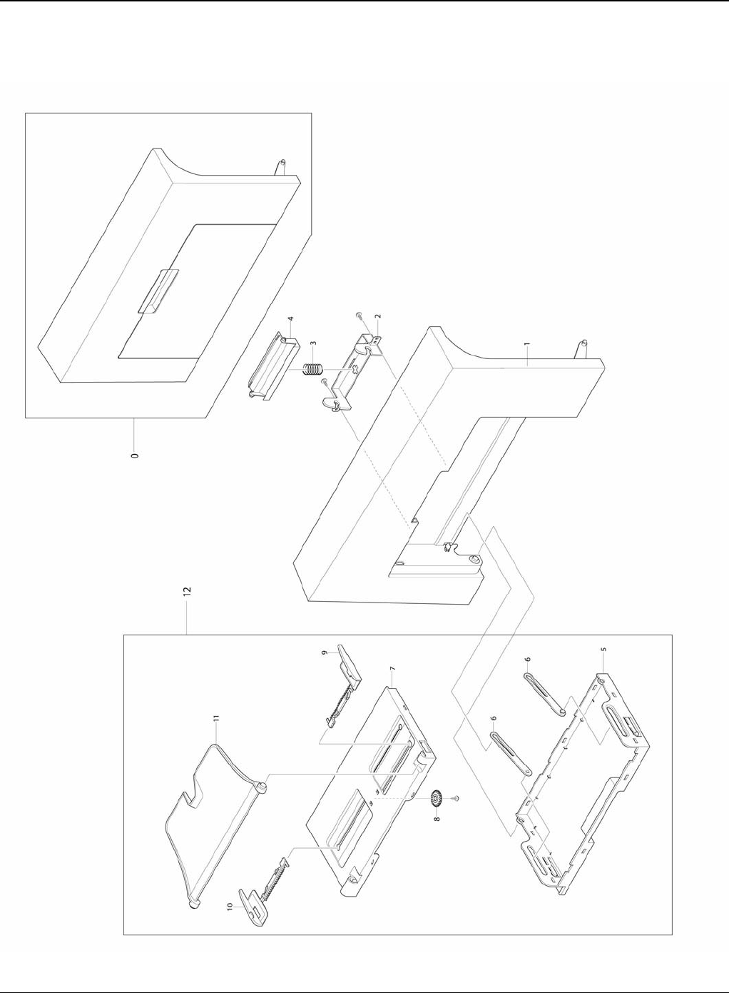
Parts List
5-6 5/08 Phaser 3435
PL 3 Front Cover Assembly

Parts List
Phaser 3435 5/08 5-7
PL 3 Front Cover Assembly
No. Part No. Description QT’y Remark
5.3-0 - MEA-COVER FRONT 1 REP 1
5.3-1 - COVER-M_FRONT 1
5.3-2 - HOLDER-M_LOCKER 1
5.3-3 - SPRING ETC-CIS(C2) 1
5.3-4 - KNOB-M_LOCKER 1
5.3-5 - TRAY-M-ASF_INPUT 1
5.3-6 - TRAY-M-LINK_MP 2
5.3-7 - TRAY-M-ASF_INPUT UPPER 1
5.3-8 - GEAR-PINION 1
5.3-9 - ADJUST-M_MP R 1
5.3-10 - ADJUST-M_MP L 1
5.3-11 - TRAY-M-ASF_FOLDER 1
5.3-12 - MP TRAY ASSEMBLY 1 REP 2
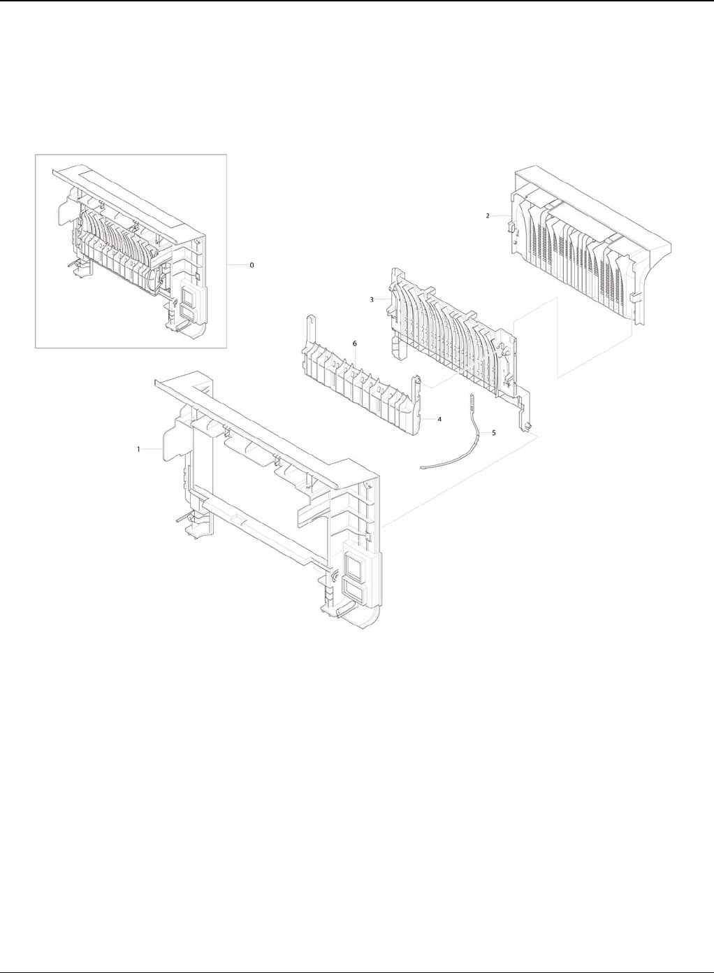
Parts List
5-8 5/08 Phaser 3435
PL 4 Rear Cover Assembly

Parts List
Phaser 3435 5/08 5-9
PL 4 Rear Cover Assembly
No. SEC.Code Description QT’y Remark
5-8
No. Part No. Description QT’y Remark
5.4-0 - MEA-COVER REAR 1
5.4-1 - COVER-REAR 1
5.4-2 - COVER-M_FACE UP 1
5.4-3 - COVER-M STACKER REAR 1
5.4-4 - GUIDE-OUTPUT FUSER 1
5.4-5 - STOPPER-M-STRAP 1
5.4-6 - GUIDE-OUTPUT F UPPER 1
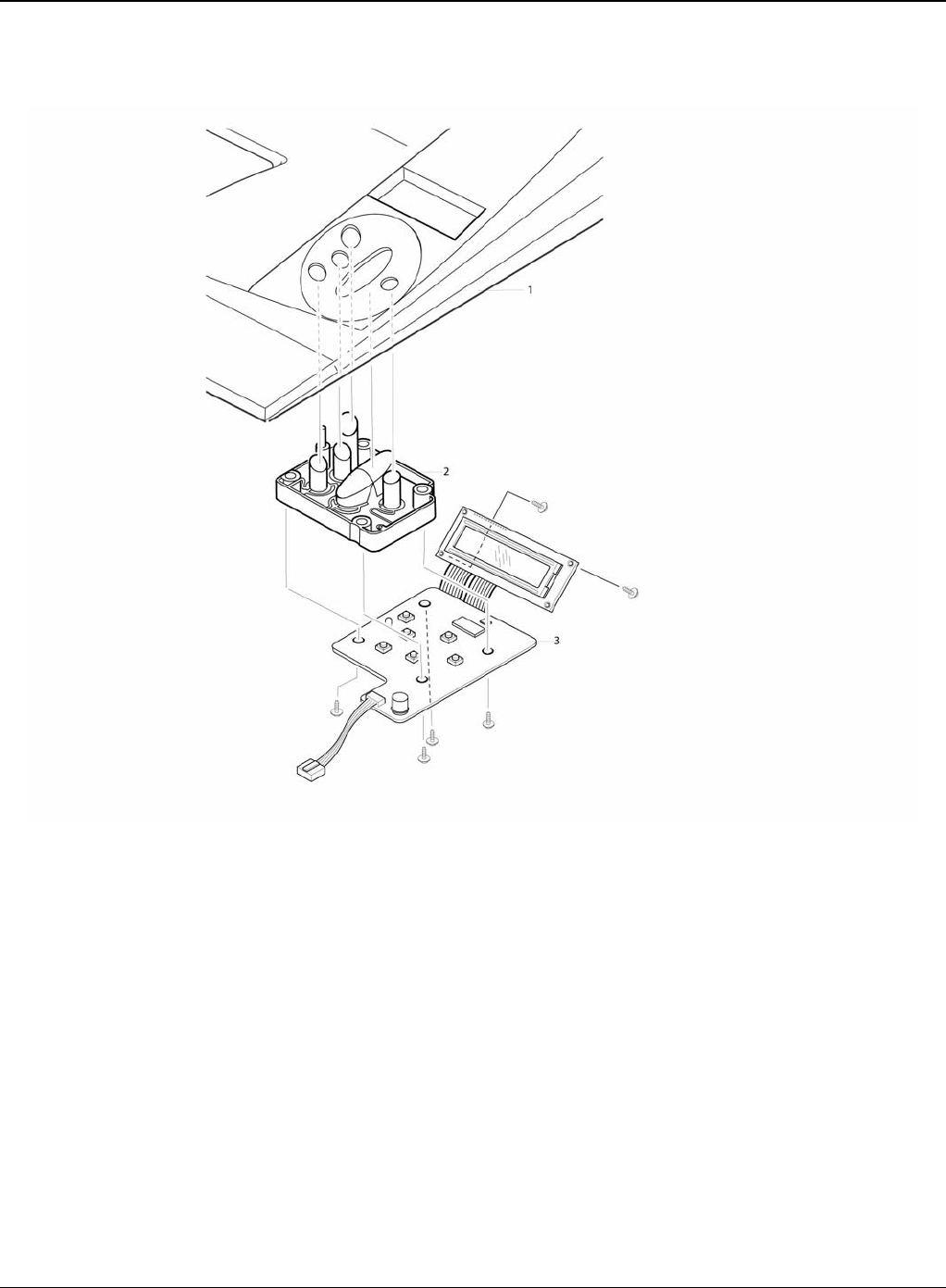
Parts List
5-10 5/08 Phaser 3435
PL 5 OPE Cover Assembly


Parts List
5-12 5/08 Phaser 3435
PL 6 Frame (1 of 3)

Parts List
Phaser 3435 5/08 5-13
PL 6 Frame (1 of 3)
No. Part No. Description QT’y Remark
5.6-0 - ELA HOU-FRAME 220V 1
5.6-0 - ELA HOU-FRAME 110V 1
5.6-1 - FRAME-M_BASE 1
5.6-2 - FRAME-M_EXIT 1
5.6-3 - ELA HOU-GUIDE DUP F 1 REP 16
5.6-3-1 - GUIDE-M_FRONT DUPLEX 1
5.6-3-2 - LEVER-ACTUATOR EMPTY 1
5.6-3-3 - PHOTO-INTERRUPTER 1
5.6-3-5 - SHEET-GUIDE FRONT DU 1
5.6-3-6 - CAM-CATCH 2
5.6-3-7 - PMO-BUSHING FEED 2
5.6-3-9 022N02292 MEA-ROLLER PICK UP 1 REP 15
5.6-3-9-1 - ROLLER-IDLE PICK UP 2
5.6-3-9-2 - HOUSING-M_PICK UP 1
5.6-3-9-3 - ROLLER-PICK UP 1
5.6-3-10 - SHAFT-PICK UP 1
5.6-3-11 - CAM-SHAFT PICK UP 1
5.6-3-12 - PMO-BUSHING_P/U,MP 1
5.6-3-13 022N02293 ROLLER-FEED 1
5.6-4 - SHAFT-FEED IDLE 1 REP 20
5.6-5 - BUSH-M-FEED IDLE 2
5.6-8 005N01031 MEA UNIT-CLUTCH 1 REP 20
5.6-8-1 - SHAFT-FEED 1
5.6-8-2 - PMO-HUB CLUTCH 1
5.6-8-3 - SPRING-TS 1
5.6-8-4 - PMO-COLLAR_SPRING 1
5.6-8-5 - GEAR-FEED 1 1
5.6-9 - MEA UNIT-BRACKET FEED 1 REP 20
5.6-9-1 - BRACKET-P-FEED 1
5.6-9-2 - GEAR-IDLE Z29 HELICAL 1
5.6-9-3 - RING-E 1
5.6-9-4 - GEAR-RETARD 39/19 1
5.6-9-5 - GEAR-T2 IDEL_Z27 1
5.6-9-6 - RING-E 2
5.6-10 - MEA UNIT-GEAR PICK UP 1
5.6-10-1 - GEAR-PICK UP_INNER 1
5.6-10-2 - GEAR-PICK UP_OUTER 1
5.6-10-3 - SPRING-CS 1
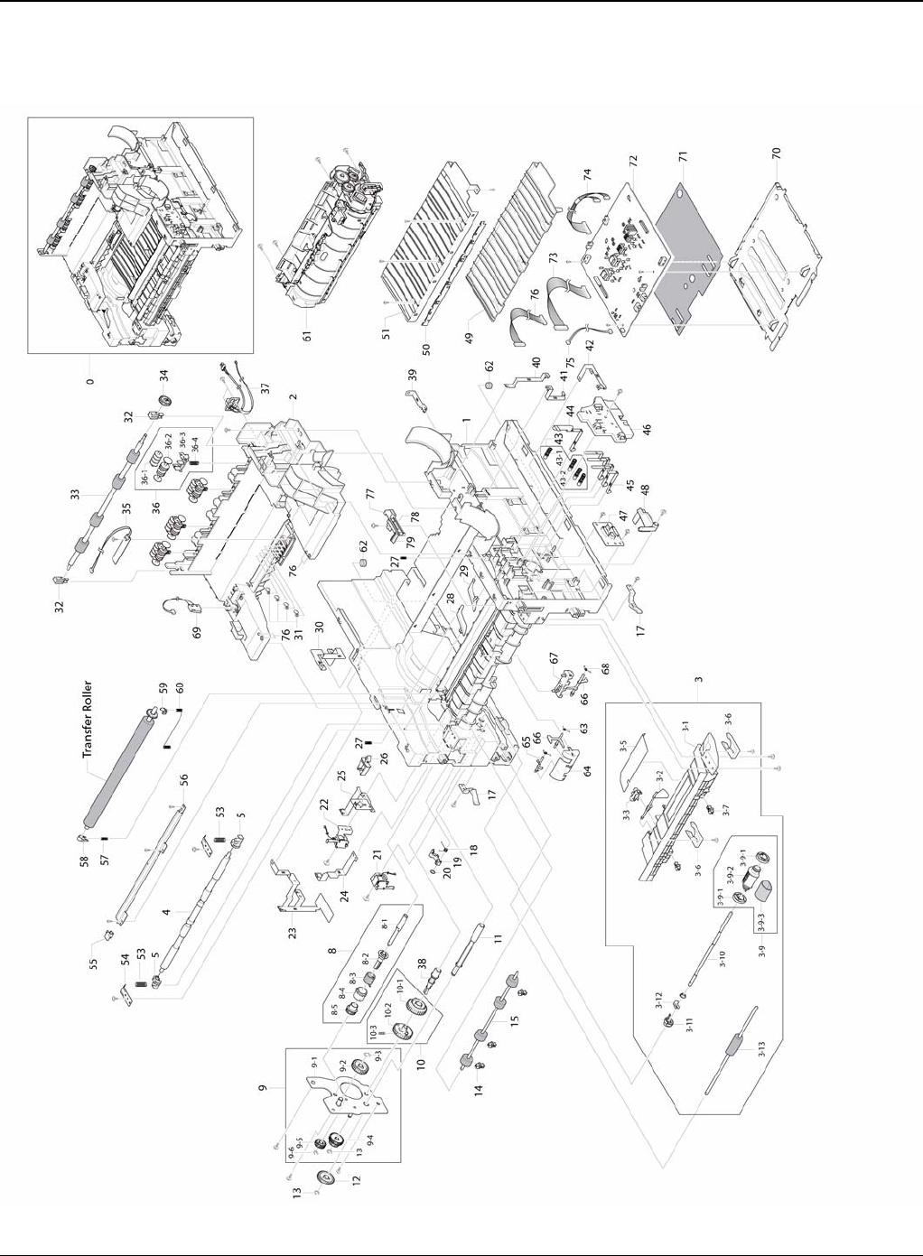
Parts List
5-14 5/08 Phaser 3435
PL 7 Frame (2 of 3)

Parts List
Phaser 3435 5/08 5-15
PL 7 Frame (2 of 3)
No. Part No. Description QT’y Remark
5.6-11 - SHAFT-M_FEED2 1
5.6-12 - GEAR-FEED2 Z27 1
5.6-13 - RING-E 1
5.6-14 -PMO-BUSHING FEED 3
5.6-15 022N02080 ROLLER-FEED ROLLER 1 1 REP 20
5.6-17 - PMO-LOCKER CST 2
5.6-18 - SPRING-TS 1
5.6-19 - CAM-M-PICK_UP 1
5.6-20 - RING-CS 1
5.6-21 - SOLENOID-MANUAL 1 REP 21
5.6-22 - SOLENOID-FEED 1 REP 21
5.6-23 - GROUND-P-DRIVE 1
5.6-24 - GROUND-P-PUSH BUSHING 1
5.6-25 - GROUND-P-DRIVE2 1
5.6-26 - CABLE CLAMP 1
5.6-27 - SPRING ETC-GUIDE DEVE 2
5.6-28 - PMO-PLATE GUIDE DEVE_L 1
5.6-29 - PMO-PLATE GUIDE DEVE_R 1
5.6-30 - GROUND-P-SHIELD 1
5.6-31 - TERMINAL-P_CRUM 4
5.6-32 - HOLDER-BEARING EXIT F/DOWN 2
5.6-33 022N02081 MEA RACK-EXIT ROLLER 1 REP 22
5.6-34 - ROLLER-EXIT F/DOWN 1
5.6-35 - PBA SUB-TERMINAL 1 REP 24
5.6-36 022N02081 MEA RACK-EXIT ROLLER 4
5.6-36-1 - PMO-ROLLER FD R 1
5.6-36-2 - PMO-ROLLER FD F 1
5.6-36-3 - PMO-HOLDER EXIT ROLL 1
5.6-36-4 - SPRING ETC-EXIT ROLL FD 1

Parts List
5-16 5/08 Phaser 3435
PL 8 Frame (3 of 3)

Parts List
Phaser 3435 5/08 5-17
PL 8 Frame (3 of 3)
No. Part No. Description QT’y Remark
5.6-39 - GROUND-P-FUSER 1
5.6-40 - GROUND-P-MOTOR FUSER 1
5.6-41 - GROUND-P-SHIELD SMPS 1
5.6-42 - GROUND-P-GUIDE TR 1
5.6-43 - MEC-TERMINAL 4
5.6-43-1 - SPRING ETC-HV APOLLO 1
5.6-43-2 - IPR-TERMINAL 1
5.6-44 - TERMINAL-P-HV CR
5.6-45 - IPR-P-TERMINAL CON 1
5.6-46 - HOUSING-M_TERMINAL 3
5.6-47 - PBA-CONNECTION 1 REP 12
5.6-48 - PMO-ACTUATOR CVR OPEN 1
5.6-49 - GUIDE-TR RIB 1
5.6-50 - PLATE-E_SAW 1
5.6-51 - GUIDE-P-TR 1
5.6-53 - SPRING ETC-TR 2
5.6-54 - PLATE-P-PUSH BUSHING 2
5.6-55 - HOLDER-M-PTL R2 1
5.6-56 - IPR-P-EARTH TRANSFER 1 REP 25
5.6-57 - SPRING ETC-TR L HAWK 1
5.6-58 - BUSH-M-TR L 1
5.6-59 - PMO-BUSHING_TR(L) 1
5.6-60 - GROUND-P-EARTH TR 1
5.6-61 - ELA UNIT-FUSER(220V) 1
5.6-61 - ELA UNIT-FUSER(110V) 1
5.6-62 - FOOT-BACK 2
5.6-63 - SPRING-TS 3
5.6-64 - HOLDER-M_ACT REGI 1
5.6-65 - LEVER-M_ACTUATOR REGI 1
5.6-66 - LEVER-M_ACT DUP OUT 1
5.6-67 - HOLDER-M_ACT FEED 1
5.6-68 - SPRING-TS 3
5.6-69 - CBF HARNESS-LSU S/W 1
5.6-70 - SHIELD-P-HVPS 1 REP 17
5.6-71 - SHEET-INSULATOR_HVPS 1 REP 17
5.6-72 112N00230 HVPS 1 REP 17
5.6-73 - CBF HARNESS-SMPS 1
5.6-74 - CBF HARNESS-ENGINE 1
5.6-75 - CBF HARNESS-PAPER EMP 1
5.6-76 - PLATE-LSU SUPPORT 1
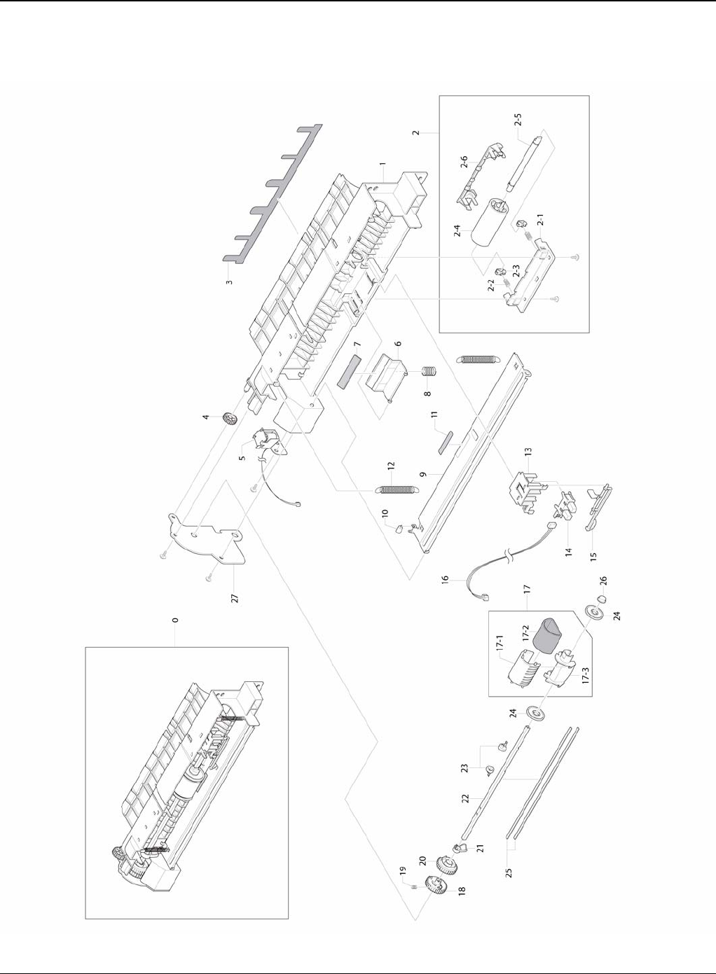
Parts List
5-18 5/08 Phaser 3435
PL 9 MP Assembly

Parts List
Phaser 3435 5/08 5-19
PL 9 MP Assembly
No. Part No. Description QT’y Remark
5.9-0 - ELA HOU-MPF 1 REP 19
5.9-1 - FRAME-M_MP 1
5.9-2 - MEA-IDLE FEED 1
5.9-2-1 - HOLDER-M_IDLE FEED 1
5.9-2-2 - SPRING ETC-EXIT LOWER IDLE 2
5.9-2-3 - HOLDER-M_SHAFT IDLE 2
5.9-2-4 - ROLLER-IDLE FEED 1
5.9-2-5 - SHAFT-IDLE FEED 1
5.9-2-6 - COVER-M_IDLE FEED 1
5.9-3 - SHEET-GUIDE MP 1
5.9-4 - GEAR-IDLE 23 1
5.9-5 121N01173 SOLENOID-MP 1
5.9-6 - HOLDER-M-PAD_MP 1
5.9-7 019N00742 RPR-FRICTION PAD 1
5.9-8 - SPRING ETC-EXIT ROLL FD 1
5.9-9 - PLATE-P-KNOCK UP_MP 1
5.9-10 - PMO-ROLLER CAM.MP 1
5.9-11 - RPR-PAD CASSETTE 1
5.9-12 - SPRING-ES 2
5.9-13 - HOLDER-M-SENSOR_MP 1
5.9-14 - PHOTO-INTERRUPTER 1
5.9-15 - PMO-M-ACT EMPTY MP 1
5.9-16 - CBF HARNESS-MPF SEN 1
5.9-17 130N01366 MEA-PICK UP_MP 1 REP 19
5.9-17-1 130N01534 RUBBER-PICK UP MP 1
5.9-17-2 - HOUSING-M_PICK UP_MP 1
5.9-17-3 - HOUSING-M-PICK UP2_R2 1
5.9-18 - GEAR-M-PICK UP_MP 1
5.9-19 - SPRING-CS 1
5.9-20 - GEAR-M-HOLDER_MP 1
5.9-21 - CAM-M_PICK UP MP 1
5.9-22 - SHAFT-P-PICK_UP 1
5.9-23 - STOPPER-M-PICK UP_R2 2
5.9-24 - PMO-IDLE PICK_UP 2
5.9-25 - SHAFT-P-CORE 2
5.9-26 - BUSH-M-PICK_UP R 1
5.9-27 - BRACKET-P-PICKUP_MP 1
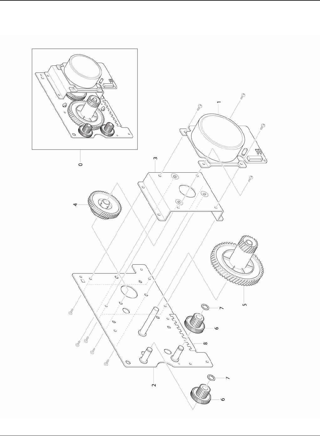
Parts List
5-20 5/08 Phaser 3435
PL 10 Main Drive Assembly

Parts List
Phaser 3435 5/08 5-21
PL 10 Main Drive Assembly
No. Part No. Description QT’y Remark
5.10-0 007N01561 ELA UNIT-MAIN DRIVE 1 REP 9
5.10-1 - MOTOR DC-BLDC MAIN 1 REP 9
5.10-2 - BRACKET-P-GEAR MAIN 1
5.10-3 - BRACKET-P-MOTOR MAIN 1
5.10-4 - GEAR-OPC RDCN 93/61 1
5.10-5 - GEAR-OPC DRV 113/33 1
5.10-6 - GEAR-FEED RDCN 55/18 2
5.10-7 - WASHER-PLAIN 2
5.10-8 - GASKET 2
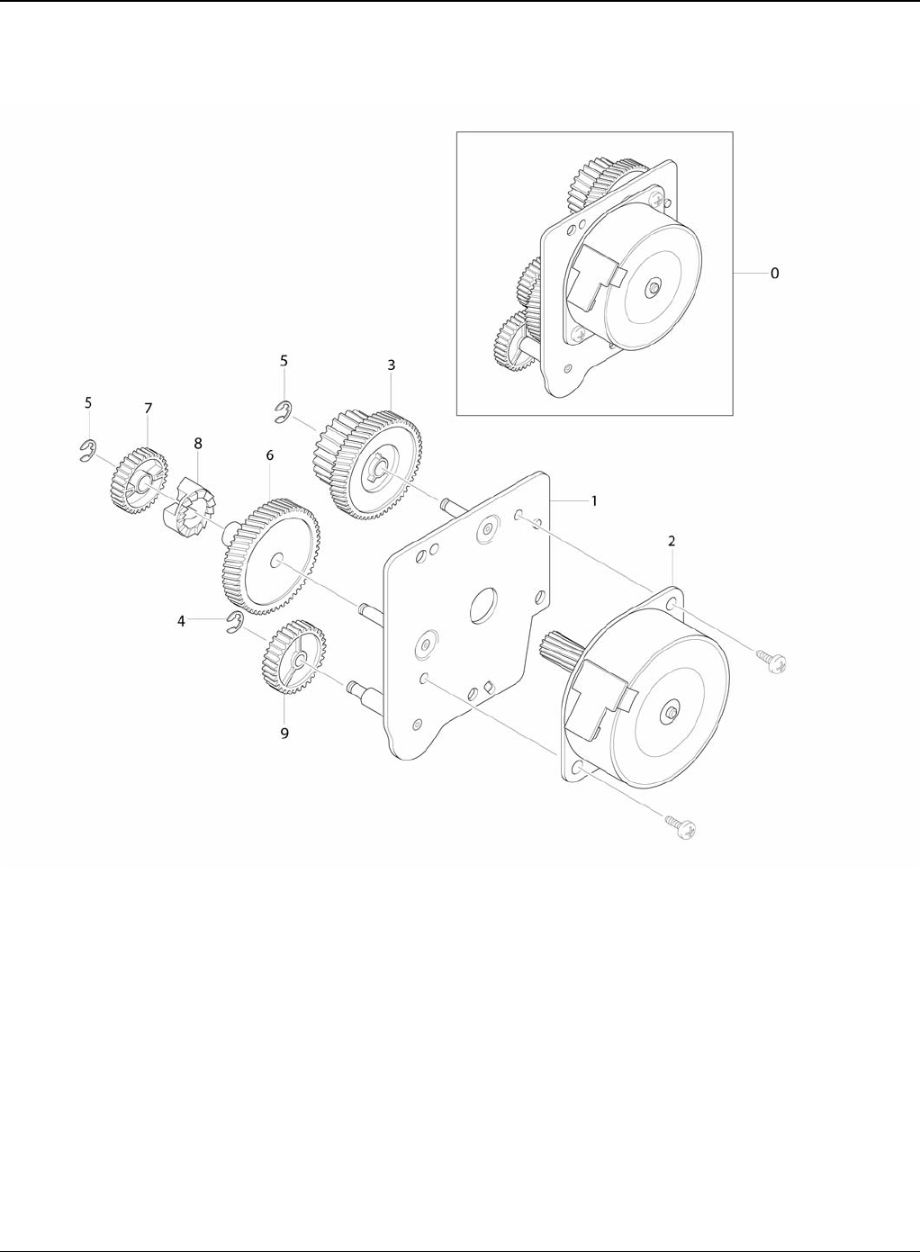
Parts List
5-22 5/08 Phaser 3435
PL 11 Fuser Drive Assembly

Parts List
Phaser 3435 5/08 5-23
PL 11 Fuser Drive Assembly
Exploded Views & Parts List
No. Part No. Description QT’y Remark
5.11-0 - ELA HOU-FUSER DRIVE 1 REP 13
5.11-1 - BRACKET-P-FUSER EXIT 1
5.11-2 127N07560 MOTOR STEP-MAIN 1 REP 13
5.11-3 - GEAR-EXIT RDCN 87/24 1
5.11-4 - RING-E 1
5.11-5 - RING-E 2
5.11-6 - GEAR-FUSER RDCN IN 95 1
5.11-7 - GEAR-RDCN FUSER OUT 1
5.11-8 - GEAR-HUB CLUTCH 1
5.11-9 - GEAR-FUSER IDLE FR 1
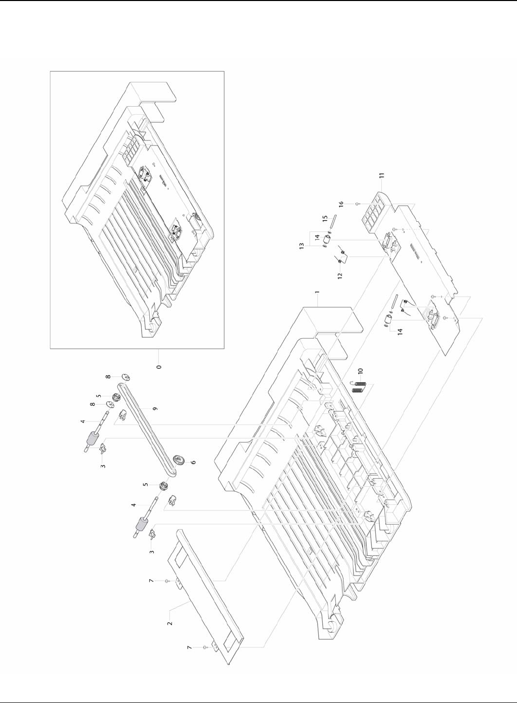
Parts List
5-24 5/08 Phaser 3435
PL 12 Duplex Unit

Parts List
Phaser 3435 5/08 5-25
PL 12 Duplex Unit
Exploded Views & Parts
List
No. Part No. Description QT’y Remark
5.12-0 - MEA UNIT-DUPLEX 1
5.12-1 - FRAME-M_DUP 1
5.12-2 - BRACKET-P-ALIGN DUP 1
5.12-3 - BUSH-M-FEED, DUP 4
5.12-4 - ROLLER-FEED_DUP2 1
5.12-4 - ROLLER-FEED_DUP 1
5.12-5 - PULLEY-18_DUP 2
5.12-6 - GEAR-EXIT F/DOWN 1
5.12-7 - SCREW-TAPTITE 2
5.12-8 - RING-C 1
5.12-9 - BELT-TIMMING 1
5.12-10 - TERMINAL-P-GND DUP 2
5.12-11 - GUIDE-M_UPPER DUP 1
5.12-12 - SPRING-TS 2
5.12-13 - PCT-SILP WASHER 4
5.12-14 - ROLLER-M-IDLE_ DUP 2
5.12-15 - SHAFT-IDLE ROLL, DUP 2
5.12-16 - SCREW-TAPTITE 4
- - ELA UNIT-ROLLER_DUP2 1
- - ELA UNIT-ROLLER_DUP 1

Parts List
5-26 5/08 Phaser 3435
PL 13 Fuser Unit (1 of 2)

Parts List
Phaser 3435 5/08 5-27
PL 13 Fuser Unit (1 of 2)
No. Part No. Description QT’y Remark
5.13-0 126N00291 ELA UNIT-FUSER (110V) 1 REP 4
5.13-0 126N00290 ELA UNIT-FUSER (220V) 1 REP 4
5.13-1 - COVER-FUSER_UPPER 1
5.13-2 - GEAR-EXIT 1
5.13-3 022N02365 ROLLER-PRESSURE 1
5.13-4 022N02301 ROLLER-PRESSURE 1
5.13-5 022N02366 ROLLER-HEAT 1
5.13-6 - BUSH-HR_R 2
5.13-7 - GEAR-FUSER 1
5.13-8 - BEARING-BALL 2
5.13-9 - SPRING-TS 2
5.13-10 - GUIDE-INPUT 1
5.13-11 - CAP-LAMP_L 1
5.13-12 - FRAME-FUSER 1
5.13-13 - GUIDE-REAR 1
5.13-14 - LEVER-LINK JAM 2
5.13-15 - SPRING-ES 1
5.13-16 - HOLDER-JAM 2
5.13-17 - BRACKET-FUSER 1
5.13-18 - CAP-LAMP_R 1
5.13-19 - HOLDER-M_REAR_LEVER 1
5.13-20 - SPRING-CS 2
5.13-21 - SPRING-CS 2
5.13-22 - SPRING ETC-ACTUATOR 1
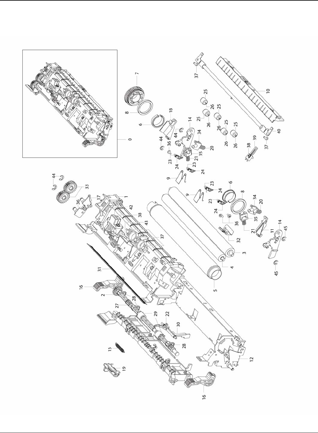
Parts List
5-28 5/08 Phaser 3435
PL 14 Fuser Unit (2 of 2)

Parts List
Phaser 3435 5/08 5-29
PL 14 Fuser Unit (2 of 2)
No. Part No. Description QT’y Remark
5.14-23 - GUIDE-CLAW 4
5.14-24 - SPRING ETC-CLAW 4
5.14-25 - PEX-ROLLER F/UP(2) 5
5.14-26 - IEX-SHAFT IDLE,F/UP 5
5.14-27 - SHAFT-EXIT_F/UP 1
5.14-28 - BUSH-TX 3
5.14-29 - RUBBER-EXIT_F/UP 2
5.14-30 - ACTUATOR-EXIT 1
5.14-31 - MEC-BRUSH ANTISTATIC 1
5.14-32 - ELECTRODE-EARTH 1
5.14-33 - GEAR-IDLE 23 FUSER 2
5.14-34 - BUSH-PR_1ST 2
5.14-35 - BUSH-PR_2ND 2
5.14-36 - SCREW-TAPTITE 4
5.14-37 - SCREW-TAPTITE 5
5.14-38 - SCREW-TAPTITE 3
5.14-39 130N01489 THERMISTOR-NTC ASSY 1
5.14-40 130N01490 THERMOSTAT 1
5.14-41 122N00260 LAMP-HALOGEN (110V) 1
5.14-41 122N00261 LAMP-HALOGEN (220V) 1
5.14-42 - CBF HARNESS-FUSER CON 1
5.14-43 - CBF HARNESS-FUSER (220V) 1
5.14-43 - CBF HARNESS-FUSER (110V) 1
5.14-44 - RING-E 2
5.14-45 - RING-E 4
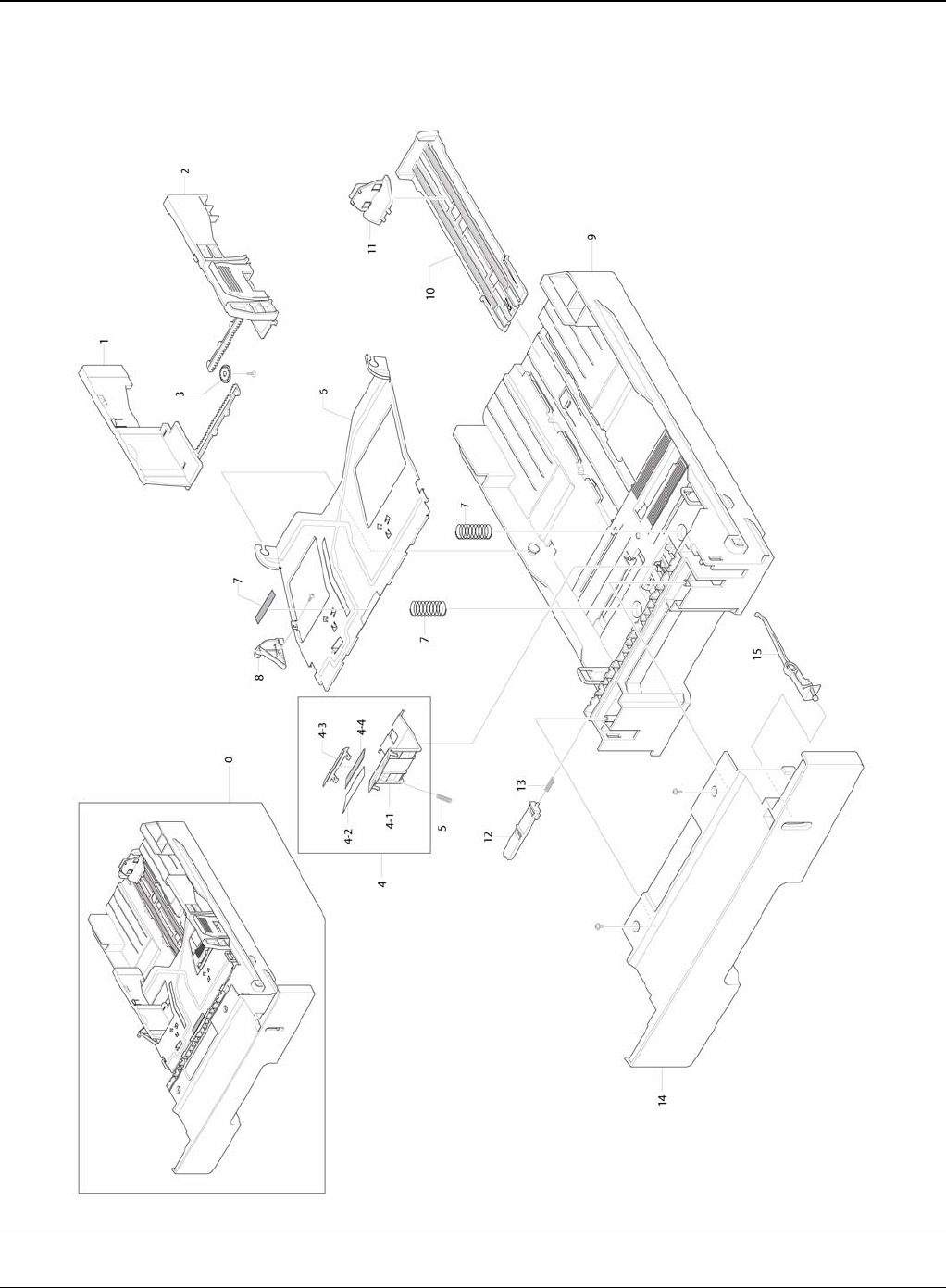
Parts List
5-30 5/08 Phaser 3435
PL 15 Cassette Unit

Parts List
Phaser 3435 5/08 5-31
PL 15 Cassette Unit
No. Part No. Description QT’y Remark
5.15-0 - MEA UNIT-CASSETTE 1
5.15-1 - ADJUST-M-CASSETTE_L 1
5.15-2 - ADJUST-M-CASSETTE_R 1
5.15-3 - GEAR-PINION 1
5.15-4 - MEA UNIT-HOLDER PAD 1
5.15-4-1 - HOLDER-M-PAD 1
5.15-4-2 - SHEET-HOLDER PAD R2 1
5.15-4-3 - IPR-PLATE PAD 1
5.15-4-4 - RPR-FRICTION PAD 1
5.15-5 - SPRING ETC-EXIT ROLL FD 1
5.15-6 - PLATE-P-KNOCK_UP 1
5.15-7 - SPRING-CS 2
5.15-7 - RPR-PAD CASSETTE 1
5.15-8 - CAM-M-KNOCK UP 1
5.15-9 - FRAME-M_CASSETTE 1
5.15-10 - GUIDE-M-EXTENSION L2 1
5.15-11 - PMO-EXTENSION SMALL 1
5.15-12 - PMO-PLATE_LOCKER 1
5.15-13 - SPRING ETC-LOCKER,PLATE 1
5.15-14 - COVER-M_SUB CST 1
5.15-15 - INDICATOR-M_CASSETTE 1

Parts List
5-32 5/08 Phaser 3435
This page is intentionally blank

General Procedures and Information
Phaser 3435 5/08 6-1
6 General Procedures and Information
GP 1 Product Specifications .................................................................................................... 6-3
GP 2 System Overview ........................................................................................................... 6-8
GP 3 Mechanical Parts Specifications .................................................................................. 6-15
GP 4 Screws Used in the Printer ............................................................................................ 6-34
GP 5 System Set-up .............................................................................................................. 6-37
GP 6 Download and Reset Firmware ..................................................................................... 6-41
GP 7 Tips for Avoiding Paper Jams ....................................................................................... 6-43
GP 8 Acronyms and Abbreviations ....................................................................................... 6-44
GP 9 Selecting Printer Locations .......................................................................................... 6-47
GP 10 Parts Life Cycle Maintenance Table .......................................................................... 6-48
GP 11 Print Cartridge Service ................................................................................................ 6-49
GP 12 Control Panel .............................................................................................................. 6-51
GP 13 Service Log ................................................................................................................. 6-52

General Procedures and Information
6-2 5/08 Phaser 3435
This page is intentionally blank

General Procedures and Information
Phaser 3435 5/08 6-3
GP 1 Product Specifications
Overview
Up to 33ppm (Ltr. 35ppm)
USB 2.0, IEEE1284
10K Print Cartridge (4K Standard)
PCL6, PS3, 1200x1200dpi
Built in Duplex
-250 sheet Cassette
-50 sheet MP
-250 sheet Opt. SCF
400 MHz, 64MB Standard
-10/100 Base TX
-Opt. 802.11b/g Wireless N/W
Specifications
Product Specifications are subject to change without notice. See below for product specifications.
General Print Engine
Controller & S/W
Item Condition Description
Engine Speed Simplex Up to 33 ppm in A4 (35 ppm in Letter)
Duplex Up to 17 ipm in A4 (17.5 ipm in Letter)
Warmup time From Sleep Less than 15 sec, Cold warm-Up time: 15sec
FPOT From Ready Less than 8.5 sec
From Idle Less than 23.5 sec
From Coldboot Less than 30 sec
Resolution - Up to 1,200 x 1,200 dpi effective output
Item Condition Description
Processor 400 MHz
Memory Std. 64 MB
Max. 320 MB
Printer Languages - PostScript3, PCL6, SPL, IBM ProPrinter, EPSON
Fonts - 45 scalable, 1 bitmap, 136 PostScript3 fonts

General Procedures and Information
6-4 5/08 Phaser 3435
Paper Handling
Driver Default Driver SPL
Supporting OS Windows 2000/XP/2003/Vista
Various Linux OS including Red Hat, Caldera, Debian, Mandrake,
Slackware,SuSE and Turbo Linux
Mac OS 8.6~9.2/10.1~10.4
WHQL Windows XP/2000/2003
Compatibility PCL6: Win95/98/NT4.0/2000/Me/XP/2003PS3: Win9x/NT4.0/2000/Me/
XP/2003 PPD, Mac PPD, Linux PPDKS/KSSM: DOS
Wired Network Protocol External: SPX/IPX, TCP/IP, SNMP, HTTP 1.1
Supporting OS Microsoft Windows 98/ME/2000/XP/2003 Microsoft Windows NT
4.xMac OS8.6 and above Various Linux OS including Red Hat, Cal-
dera, Debian, Mandrake, Slackware, SuSE and Turbo LinuxNovell
4.x,5.x,6.x
Wireless Network Protocol External: SPX/IPX, TCP/IP, SNMP, HTTP 1.1
Supporting OS Microsoft Windows 98/ME/2000/XP/2003 Microsoft Windows NT
4.xMac OS8.6 and above. Various Linux OS including Red Hat, Cal-
dera, Debian, Mandrake, Slackware, SuSE and Turbo LinuxNovell
4.x,5.x,6.x
Application RCP N/A
Status Monitor N/A
Smart Panel YES (RCP,SM)
Network Management SAS, SetIP
Interface
Parallel USB - IEEE 1284
- USB 2.0
Wired Network - Ethernet 10/100 Base TX (Internal)
Wireless Network - Optional (Internal) Optional (Internal) 802.11b/g Wireless
LAN (Internal)
User Interface
LCD - 2 x 16 Character without backlit
LED - 3 LED (Status, Toner Save, N-Up)
Key - 8 Key: Stop, Toner Save, N-Up<, OK, >, Menu, Back
Item Condition Description
Standard Capacity - 250-sheet Cassette Tray, 50-sheet Multi Purpose Tray @ 75g/
Max. Capacity - 550 sheets @ 75g/
Printing Max. Size 216 x 356 mm (8.5" x 14")
Min. Size 76 x 127 mm (3.0" x 5.0")
Multi-purpose tray
Capacity - 50 sheets @ 75g/ (20lb bond)

General Procedures and Information
Phaser 3435 5/08 6-5
Media sizes - A4, A5, A6, Letter, Legal, Folio, Oficio, Executive,ISO B5, JIS
B5,3"x5",Monarch, No.10, DL, C5, C6
Media type - Plain Paper, Transparency, Envelope, Labels, Post Card, Card
stock
Media weight - 16~43lb (60 to 163g/)
Sensing - Paper empty sensor
Standard Cassette
Tray
Capacity - 250 sheets @ 75g/
Media sizes - A4, A5, Letter, Legal, Executive, Folio, Oficio, ISO B5, JIS B5
Media types - Plain paper, Thick, Thin, Recycled, Archive
Media weight - 16~28lb (60 to 105g/)
Sensing - Paper empty sensor
Optional Cassette
Tray
Capacity - 250 sheets @ 75g/
Media sizes - A4, A5, Letter, Legal, Executive, Folio, Oficio, ISO B5, JIS B5
Media types - Plain paper, Thick, Thin, Recycled, Archive
Media weight - 16~28lb (60 to 105g/)
Sensing - Paper empty sensor
Output Stacking
Capacity Face-Down 150 sheets @ 75g/
Face-Up 1 sheet @ 75g/
Output Full sensing - N/A
Capacity Face-Down 150 sheets @ 75g/
Face-Up 1 sheet @ 75g/
Output Full sensing - N/A
Duplex
Supporting - Built-in
Media sizes - A4, Letter, Legal, Folio, Oficio
Media types - Plain Paper
Media weight - 20~24lb (75 to 90g/)

General Procedures and Information
6-6 5/08 Phaser 3435
Consumables
Reliability & Service
Environment
Memory
The Phaser 3435 has 64MB of memory which can be expanded to 320MB.
Item Condition Description
Toner Black 4,000 pages @ ISO 19752 Coverage (Standard 4,000 pages,
High Yield10,000 pages)
Key Electronic key (CRUM) Only
Life detect Toner gauge sensor by dot count
Drum Yield 12,000 Images
Item Condition Description
Printing Volume (SET
AMPV) - 9,200 sheets-per year / 767 sheets-per month / 38 sheets-per
day
5.2 Max. Monthly
Duty - 35,000 sheets
5.3 MPBF - 100,000 sheets
5.4 MTTR - 30 min.
5.5 SET Life Cycle - 250,000 sheets or 5 years (whichever comes first)
5.6 RDS Comm. Mode Yes
Operation Yes
Item Condition Description
Acoustic Noise Level
(Sound Power/Pres-
sure)
Printing Less than 52.0 dBA
Standby Less than 26.0 dBA
Sleep Back Ground Level
Power Consumption Ready Less than 130W
AVG. Less than 400W
Max/Peak Less than 700W
Sleep/Power Off Less than 11W / Less than 0.4W
Dimension (W x D x H) SET 400 x 433 x 285 mm (15.7 x 17 x 11.2 inches)
Weight SET 10.5 kg (23.15 Pounds)
Gross 14.5kg (31.9 Pounds)

General Procedures and Information
Phaser 3435 5/08 6-7
Others
Item Condition Description
Memory Upgradable Mem.
Slot 1 EA
Upgradable Mem.
Type 100 Pin SDRAM DIMM
Upgradable Mem.
Unit 128MB, 256MB
Sensor Paper Empty YES
Paper Size NO
Media Type NO
Paper Full NO
Service Service Item &
Period 1. Transfer Roller: 70K pages
2. Fuser Unit: 80K pages
3. Pick-up Roller: 150K pages
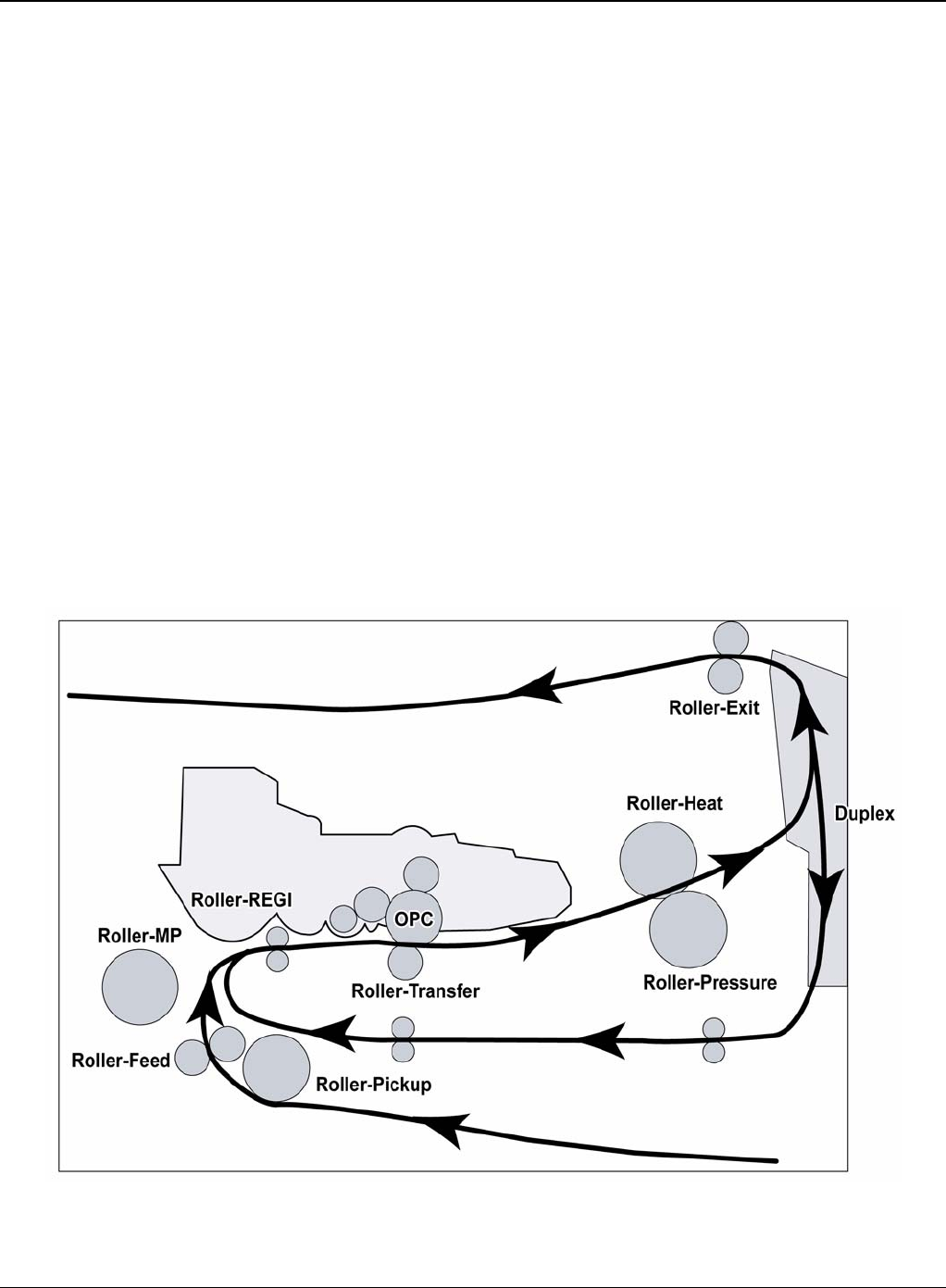
General Procedures and Information
6-8 5/08 Phaser 3435
GP 2 System Overview
Construction
Summary
The Phaser 3435 is consisted of the Engine parts and F/W, and said engine parts is consisted of
the mechanical parts comprising Frame, Feeding, Developing, Driving, Transferring, Fusing, Cab-
inet and H/W comprising the main control board, power board, operation panel, PC Interface.
• The main controller is consisted of Asic(SPGPv3) parts, Memory parts, Engine Interface parts
and it functions as Bus Control, I/O Handling, drivers & PC Interface by CPU.
Memory Access supports 16bit Operation, and Program Memory 32MB and Working Memory
as well.
• The paper path is consisted of 250 sheets Cassette containing friction Pad, pickup-roller,
feed-roller for functioning as registration, Earth-transfer for guiding the transfer inlet, Guide-Tr
for guiding sheets
between transferring and fixing, Fuser, Exit Assy.
• The driving device is consisted of f55 BLDC motor, OPC, Pick-up, Feed, Gear-Train con-
nected with Mounting member.
System Layout
Figure 1
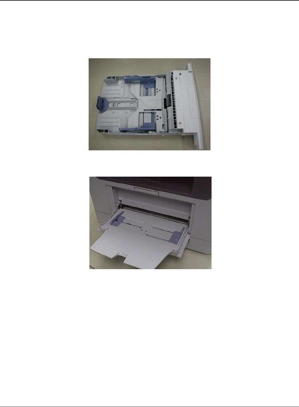
General Procedures and Information
Phaser 3435 5/08 6-9
Feeding Section
• Feeding Method: Universal Cassette Type
• Feeding Standard: Centre Loading
• Feeding Capacity: Cassette 250 Sheets (75g/20lb Standard Paper)
Figure 2
Figure 3
Transfer Assembly
• In Warranty (Life time): Within 70,000 sheets printing
Cassette
MPF
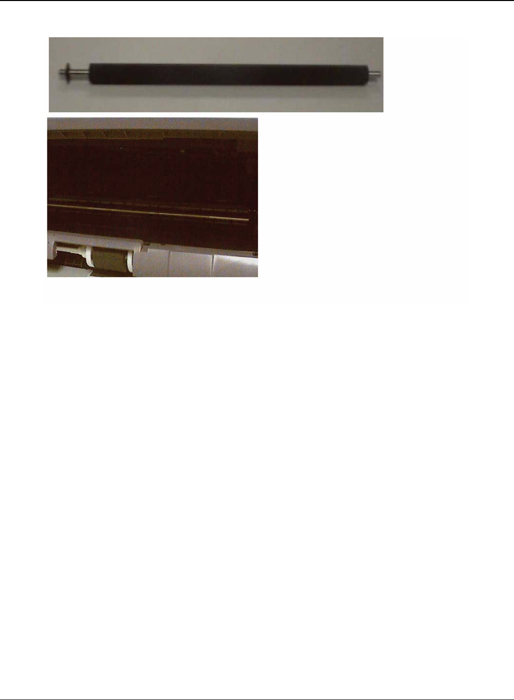
General Procedures and Information
6-10 5/08 Phaser 3435
Figure 4
Product specification and feature
Driver Assembly
• MAIN Motor assembly is for Cassette, MPF and Print Cartridge.
• EXIT Motor assembly is for fuser, exit roller and the initial duplex feeding.
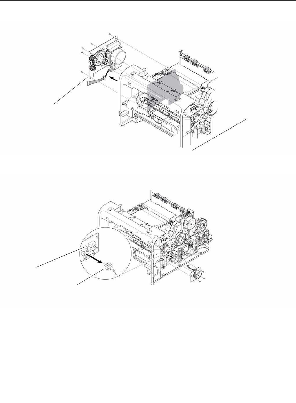
General Procedures and Information
Phaser 3435 5/08 6-11
Figure 5
Figure 6
Fuser Assembly
• Fusing Type: Lamp Type
• Heat Roller: [28.3 with 0.1 Crown]
• Pressure Roller Pressure Roller 2: [electrically conductive]
• Thermistor - Temperature Detecting Sensor
• Thermostat - Overheat Protection Device
Drive assembly
Connection PCB
Duplex motor
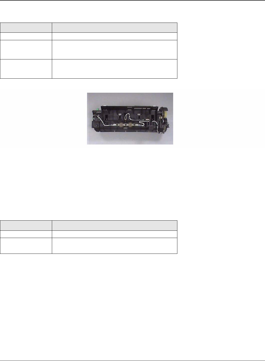
General Procedures and Information
6-12 5/08 Phaser 3435
Figure 7
LSU
• LSU is consist of LD (Laser Diode) and polygon motor control. When the controller generate
the printing signal LD will turn on and Polygon motor starts. If the receiving part in LSU detect
the beam and then Hsync is generated. When the rotation of polygon motor is steady, it is
time of LSU ready status for printing. If either of two condition is not satisfied, LSU error is
expected.
Print Cartridge
• OPC Cleaning: Mechanical Cleaning by the cleaning blade.
• The recycled toner: Trash room for the recycled toner
• No shutter for protecting the OPC Drum
Trouble Temperature Control Concept
Open Heat Error 50 degrees C for 20 sec at warm up
Over Heat Error 240 degrees C over for 2 sec or 220 degrees C over
for 20 sec at ready or printing.
200 degrees C over for 10 sec at standby.
Low Heat Error Standby: 130 degrees C below for 10 sec.
Printing: It 30 degrees C lower than target tempera-
ture for 20 sec.
Trouble Failure Analysis
Polygon Motor Error No steady rotation of Polygon Motor
Hsync Error In spite of steady rotation of Polygon Motor, There is
no generation of the Hsync signal
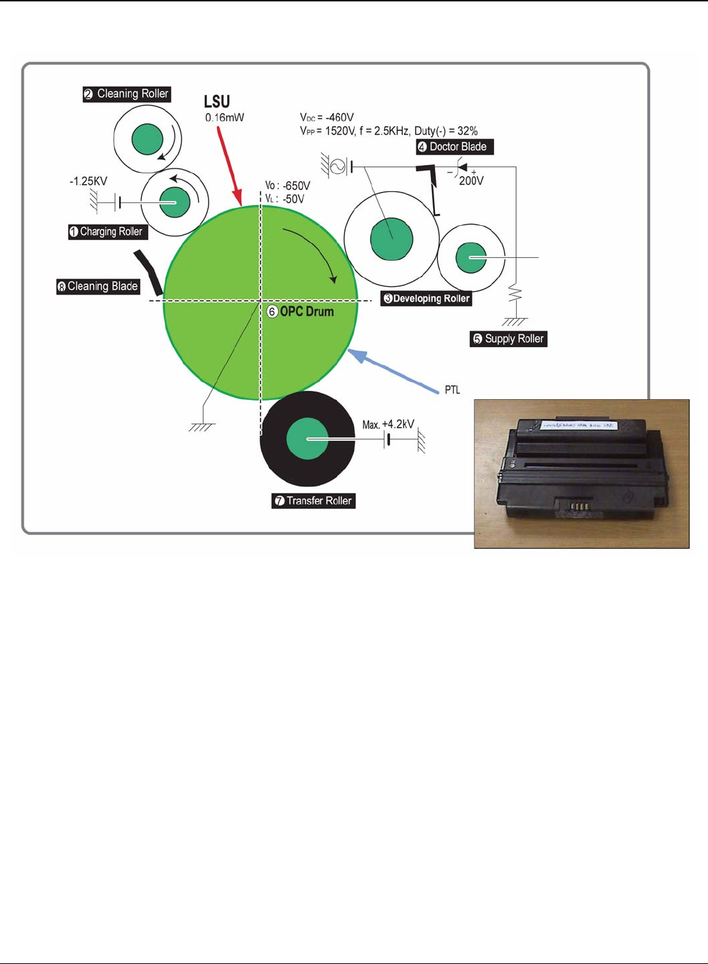
General Procedures and Information
Phaser 3435 5/08 6-13
Figure 8
Duplex Unit
• Available Paper: Letter, Legal, Folio, Oficio and A4.
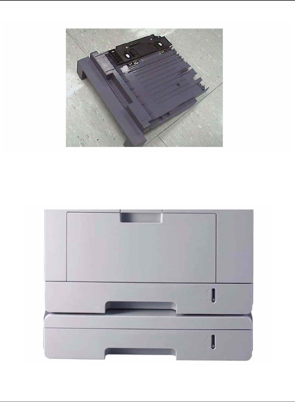
General Procedures and Information
6-14 5/08 Phaser 3435
Figure 9
Optional Tray (SCF)
• For customer convenience in managing paper
• Capacity: 250 sheets
Figure 10

General Procedures and Information
Phaser 3435 5/08 6-15
GP 3 Mechanical Parts Specifications
Frame
• Material: PC + ABS V0 NH-1000T(Cheil Industries)
• Weight: 1.0kg
Feeding Part
• Feeding Type: Universal Cassette Type
• Feeding Standard: Centre Loading
• Feeding Qty: Cassette 250 sheets (75g/20Ib paper standard) MPF 50 sheets (75g/20Ib paper
standard) Special Media 5 sheets in MPF (OHP, Envelope, Label, Post Card, Index Paper
etc.)
• Separating Type: Cassette-Friction Pad Type MPF-Friction Pad Type
• Driver Type: Driving by Gearing from Main Motor
• Pick Up Roller Driver: Solenoid
• Pick Up Roller Rubber Material: EPDM + IR = 1.6 or more
• Paper detecting Sensor: Photo Sensor
• Paper Size Sensor: None
• Paper Separating Pad Material: NBB 52 = 0.8~1.2
• Separating Pad Pressure: 190gf
• Feeding Pressure (Cassette): 250 gf 10% (SPRING H mm, based on 1 sheet 320 gf 10%
(SPRING H mm, based on 250 sheet)
• Paper Exit Type: Face Down
• Feed Roller Driver: Solenoid
Transfer Assembly
It is consisted of PTL (pre-transfer lamp) and Transfer Roller. The PTL sends a light to the OPC
drum, makes the current on the drum surface to low, and improve the transfer efficiency.The trans-
fer roller delivers the toner of the OPC drum to the paper
• TR Voltage: +1.3KV +/-5%
-1.20KV +/-10% (In cleaning)
• Transfer Trigger Current: 6.5 micro amps +/- 5%
• Transfer Efficiency: 85% or more (All environment: preferable media)
• Voltage System: Voltage PWM Control System
• Transfer Roller
-Material: NBR FOAM ROLL
-Structure: Mono layer
-Resistance: 3E +07 ~ 8E +07 ohms (N/N)
- Hardness: 40 3% (ASKER-C)
-Valid length: 224.2 +0.5/-0mm
- OD: 15.0 +/-0.5mm
-SHAFT Material: SUM -24L + Non-electrolysis Ni. Coating
• Life Span: Print over 70,000 sheets (in 15~30 degrees C)

General Procedures and Information
6-16 5/08 Phaser 3435
Driver Assembly
Motor
• Spec: BLDC 62 dia + PM 55 dia Motor (2-2 Bipolar) + PM 42 dia Motor (2-2 Bipolar)
• Pull-Out Torque:
BLDC 62 dia: 1500 gf.cm(based on actual value) or more (1342.4rpm, 1.8A)
PM 55 dia: 1490gf.cm(based on actual value) or more (711pps, 0.9A)
PM 42 dia: 240gf.cm(based on actual value) or more (1850pps, 0.6A)
• TORQUE MARGIN (Tp/o Tsys): BLDC 62 dia Motor: 1500/1100 gf.cm=1.36
PM 55 dia Motor: 1490/1053 gf.cm = 1.41
PM 42 dia Motor: 240/165 gf.cm = 1.45
Driving Frequency: BLDC 62 dia Motor: 1342.4 rpm(1006.8 Clock)
PM 55 dia Motor: 888.75 rpm(711 pps)
PM 42 dia Motor: 1156. 25rpm(1850 pps)
• It is a power delivery unit by gearing: BLDC 62 dia Motor -> Pickup/Feeder/Developer PM 55
dia Motor -> Fuser/Exit PM 42 dia Motor -> Duplex
Process Speed
• Print Speed: 33/35 PPM (based on A4/LTR)
• Process Speed: 211.78 mm/sec
• Jitter
Vertical: 0.018 or less in Vision System
Horizontal: within 2% of partial magnificence error
• Orthogonality: SPEC: +/-1.0 mm or less
Acoustic Noise
• Warming Up: 43dB or less
• Printing: 52dB or less
• Stand-by: 26dB or less
Fixing Part (Fuser)
The fuser consists of a halogen lamp, 2 pressure rolls, Thermistor and Themostat. It adheres the
toner to the paper with pressure and a heat to complete the printing job.
Halogen Lamp
• Voltage: 120V: 115 +/-5%
220V: 230 +/-5%
• Capacity: 800 Watt 25W
• Temp. Distribution: 120%

General Procedures and Information
Phaser 3435 5/08 6-17
Temperature-Interception Device (Thermostat)
• Thermostat Type: Non-Contact type THERMOSTAT
• Control Temperature: 170 degrees C +/-5 degrees C
• THERMOSTAT-ROLLER Gap: 1.6 +/-0.2mm
Temperature Detecting Sensor (Thermistor)
• Thermistor Type: HF-R0060 (SEMITEC 364FL Type)
• Temperature Resistance: 7k ohms (180 degrees C)
• SYSTEM Temperature SETTING
-Stand by: 165 +/-5 degrees C
- Printing: 189 +/-5 degrees C (5 minutes before)
184 +/-5 degrees C (5 minutes after)
-Overshoot: 200 degrees C less
-Overheat: 210 degrees C less
Heat Roller
• Length: 247.5mm
• Valid length: 224mm
• OD: 28.3 + 0.05, -0.03 (Tubing incl., Crown 0.09~-0.15)
• Material: AL(AL5052) + PFA Tubing
• Thickness: 0.9mm
• Coating Material: PFA 100% Coating Thickness: 20um (Thickness after abrasion) GND
• Type: H/R Bearing Grounding type By SECC Fuser lower frame
Pressure Roller
• Shaft
-Length: 251.3mm
-Material: SUM
- Thickness: 6 dia (14 dia - RUBBER portion)
• Rubber 1
- Material: Silicon Rubber (Tubing Type: 20 dia)
-Length: 226.4mm
-Thickness: 5mm (one-side)
• Rubber 2
- Material: Silicon Rubber (Tubing Type: 16 dia)
-Length: 226.4mm
-Thickness: 5mm(one-side)
• OD: 1) 20 +/-0.2(Center part Crown -0.2)
2) 16 +/-0.2(Center part Crown -0.15)
Media Separating System
PI Coating with PPS Claw System

General Procedures and Information
6-18 5/08 Phaser 3435
Safety Relevant Facts
• Protecting device when overheating
-1st protecting device: H/W cuts off when detecting an overheating
-2st protecting device: S/W cuts off when detecting overheating
-3st protecting device: Thermostat cuts off the power
• Safety device
-The power of Fuser is cut-off after front cover is open
-The overheating safety device for customer
-The surface temperature of the Fuser Cover is under 80 degrees C
LSU (Laser Scanner Unit)
The LSU unit is controlled by video controller. It scans the video data received from video control-
ler with laser beam by
using the rotation principle of the polygon mirror to create the latent image on the OPC drum. It is
the core part of LBP. The OPC drum rotates as the same speed as the paper feeding speed. It
creates the /HSYNC signal and sends it to the engine when the laser beam of the LSU reaches
the end of the polygon mirror, and the engine detects the /HSYNC signal to arrange the vertical
line of the image on the paper. After detecting the /HSYNC signal, the image data is sent to the
LSU to arrange the its margin on the paper.
The one side of the polygon mirror is one line for scanning.
Print Cartridge
In the print cartridge, the OPC unit and the developer unit are in a body.
The OPC unit has OPC drum and charging roller, and the developer unit has toner, print cartridge,
supply roller, developing roller, and the blade.
Summary
• Developing Method: Non magnetic 1 element contacting method
• Toner: Non magnetic 1 element shatter type toner
• Charging capacity: -39.1+/-3 C/g (KAO meas. method)
•Average OD: 8.5 +/-0.5 (Toner)
• Toner Qty: 125 gf/250gf (4k / 10k)
• The life span of print cartridge: 4k/10k sheets (ISO 19752 Pattern / A4 standard)
• Toner Residual Sensor: Dot count with CRUM (CRU Monitor)
• OPC Cleaning: Collect the toner by using cleaning blade+ FILM OPC
• Handling of wasted toner: Collect the wasted toner in the cleaning frame by using cleaning
blade
• OPC Drum Protecting Shutter: None
• Classifying device for print cartridge: ID is classified by interruption of the frame channel.

General Procedures and Information
Phaser 3435 5/08 6-19
Developing Roller
• Roller type: conductive elastic roller
• Rotary Speed: 203.06 mm/sec
• Roller Bias: -220V ~ -400 20V
• Control Type: Bias PWM Control type
• Roller material: Conductive NBR + Surface UV process
-Structure: Mono layer
-Resistance: 1.0E+03~ 1.5E+06 ohms (N/N Condition)
- Hardness: 52 degrees +/-5 degrees
-Valid Length: 228 mm
- OD: 14.07 mm +/-0.05
-Shaft material: SUS 303
-Surface roughness (Ra): Ra 2.0 ~ 2.5 (Circular-direction)
-Friction coefficient (u): 0.1 ~ 0.5 (70gf, 50mm/min, OHP (3M,#CG3300))
-Life: 100,000 sheets or more
Supply Roller
• Rotary Speed: 131.98 mm/sec
• Roller Bias: -370V ~ -550V
• Control Type: Bias
• Roller material: Nylon Fur
-Structure: Closed cell
- Resistance: 0.6E+05 ~ 3.0E+06 ohms (N/N cond.)
- Hardness: 16 ~ 25 degrees (Asker "C")
- Valid Length: 218 mm
- OD: 11.2 +/-0.1 mm
- Shaft material: SUM 24L Non-electrolysis Ni. Coating
- Shaft OD: 8.2 mm + 0 / -0.05
- Driver: Gear Driver (in a direction opposed to D/R)
- Sponge Density: 0.45, +/-0.1 g
- Life: 10,000 sheets or more
Regulating Blade
• Type: Regulating toner layer by pressure
• Material: SUS 301 1/2H CSP t0.08
• Valid Length: 228mm
• Voltage: -420V ~ -600V
• Regulating edge R value: 0.3 +/-0.02mm
• Pressure: 42 gf/cm

General Procedures and Information
6-20 5/08 Phaser 3435
Charging Portion
• Type: Conductive Roller Contact-Charge
• Rotary Velocity: 179.7 mm/sec
• Surface potential: -760 +/-70V (based on OPC, N/N cond.)
• Residual potential: -130 V or less (initial)
• Control Type: Bias PWM Control
• Roller material: Conductive elastic roller (Conductive NBR + SBR)
-Structure: Mono layer (Surface UV process)
-Resistance: 0.75E+06 ~ 5.0E+06 (N/N cond.)
-Hardness: 50 degrees +/-3 degrees
-Length: 230 mm
- OD: 12.0 +/-0.05 mm
-Shaft Material: SUM-24L + Non-electrolysis Ni Coating
- Shaft OD: 6 +0 / -0.05 mm
-Driver: Gear Driver
-Pressure: L:300 gf / R:350 gf
-Roller surface roughness: Ra 1.8 um or less (shaft direction)
-Roller life: 10,000 sheets or more
• Roller Voltage: -1.25 ~ -1.70 KV
Engine H/W Specifications
Main Board
The Engine Board and the Controller Board are in one united board, and it is consisted of CPU
part and print part in functional aspect. The CPU is functioned as the bus control, I/O handling,
drivers, and PC interface. The main board sends the Current Image of Video data to the LSU and
manages the conduct of Electrophotography for printing. It is consisted of the circuits of the motor
(paper feed, pass) driving, clutch driving, pre-transfer lamp driving, current driving,
and fan driving. The signals from the paper feed jam sensor and paper empty sensor are directly
inputted to the main board.

General Procedures and Information
Phaser 3435 5/08 6-21
Asic(SPGPv3)
• CPU Core: ARM1020E
-32KB instruction cache and 32KB data cache
• Operating Frequency
-CPU Core: over 300MHz
-System Bus: 100MHz
•SDRAMC
-32Bits Only, 100MHz
-5 Banks (Up to 128MB per Bank)
• ROMC
-4 Banks (Up to 16MB per Bank)
• IOC
-6 Banks (Up to 16MB per Bank
• DMAC
-4 Channels
• HPVC
-Dual/Single Beam
-LVDS Pad (VDO, HSYNC)
• UART
-5 Channels (1 Channels Supports DMA Operation)
• PCI Controller
-32Bits, 33/66MHz
-PCI Local Bus Specification rev2.2 Complaint
-Host / Agent Mode (Support 4 Devices in Host Mode)
• NAND Flash Controller
-8/16Bits, H/W EEC Generation
-Auto Boot Mode (Using Internal SRAM, 4KB)
•MAC
-10M/100Mbps
-Full IEEE 802.3 Compatibility
• Engine Controller
-LSU Interface Unit
-Step Motor: 2 Channels
-PWM: 8 Channels
-ADC: 6 Channels
• I2C Controller
-I2C(S-BUS) Slave Device Support(I2C Version 2.1)
• RTC
-RTC Core Voltage: 3V PLL
-3 PLL: MAIN, PCI, PVC
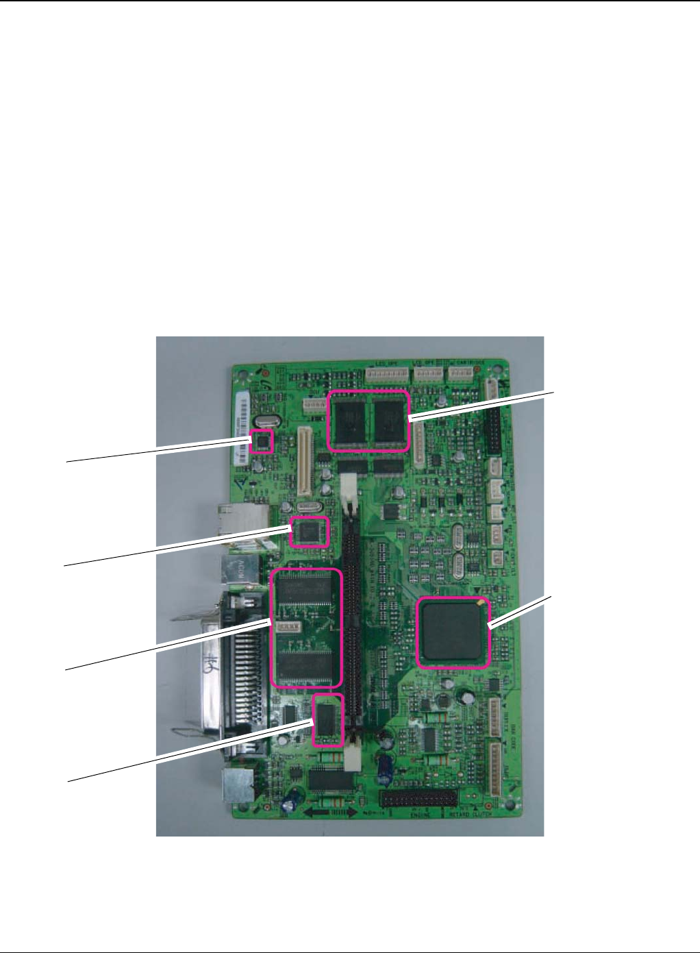
General Procedures and Information
6-22 5/08 Phaser 3435
Memory
• Flash Memory: It stores System Program and downloads the System Program through PC
Interface, and in case of model for export it compresses the PCL font, then stores it.
-Capacity: 32M Byte (NAND Flash)
-Random Access Time: 10 us (Max)
-Serial Page Access Time: 50ns (Min)
• DRAM: It is used as Swath Buffer, System Working Memory Area, etc. when printing.
It stores Font List, compressed into Flash memory, on DRAM and uses it as PCL font in case
of model for export.
-Capacity: 64M Byte (Basic), up to 320Mbyte (User Option)
-Type: SDRAM 100MHz/133MHz, 16bit
Others
The Option PBA can be mounted for supporting the serial communication.
Figure 1
Flash ROM
SPGPv3
(ASIC)
PHY IC
USB IC
SDRAM
SRAM

General Procedures and Information
Phaser 3435 5/08 6-23
Flash Memory
It stores the system program and downloads system program through the PC Interface.
• Capacity: 16M Byte (NOR Flash)
• Access Time: 90ns
• Page read Time: 25ns
SDRAM
It is used as swath buffer, system working memory area, etc. while Printing.
• Capacity: The 64M Bytes is for this model (64M: Printing System Working Memory Area)
Sensor Input Circuit
• Paper Empty Sensing
The Paper empty sensor (Photo Interrupter) on the HVPS informs the state of paper to
CPU whether it is empty or not with operation of the actuator.
When cassette is empty, it detects the fact by reading the E20 of CPU, and then informs
the fact by displaying the RED.
• MP Sensing
By operation of Actuator on the frame, an individual MP Sensor (Photo interrupter)
informs the state of paper to CPU whether it is empty or not. It reads the D17 of CPU for
recognizing paper in MP, and paper is fed from MP if there is.
• Paper Feeding/With Print Cartridge Sensing
When paper passes the actuator (feed sensor part), it detects the signal of Photo inter-
rupter, informs the paper feeding state to CPU, and then sprays the image data after cer-
tain time. If it doesn’t detect the feed sensor within 1sec. after paper is fed, paper Jam0 is
occurred (LED will be display RED color). The fact whether the developer is inserted or
not is detected by CRUM. After the developer is mounted, the sub-CRUM can read the
information of print cartridge from contact with CRUM involved in print cartridge. If the
information of print cartridge is invalid, it will show invalid sign on a LCD or LED.
• Paper Exit Sensing
It detects paper state whether paper gets out from the set with operation of exit sensor on
the HVPS and actuator on the frame. Paper detects the on/off time of exit sensor by read-
ing D22 of CPU, and the normal operation or jam information is informed to the CPU.
The paper JAM2 is informed. (LED will be display RED color)
• Cover Open Sensing
The Cover open sensor is located on the HVPS. After the front cover is opened, +24VS
(DC fan, Solenoid, Main Motor, Polygon motor part of LSU and HVPS), which is supplied
to the each unit, is cut off. The cover-open sensing is operated by the D23 of CPU. In
case, the red will be ON for informing the facts to user.
• DC FAN / Solenoid Driving
It is driven by transistor and controlled by D14(FAN MAIN), E16(FAN DUPLEX),
C23(PICK-UP CLUTCH), C18(REGICLUTCH), D15(MPF CLUTCH) of CPU. When it is
high, the fan is driving by turning on the TR, and it is off when the sleep mode is selected.
There are three solenoids, and they are driven by paper pick-up, regi and MPF signal. It is
turned on or off by C23, C18, D15 of CPU. The diode protects the driving TR from the
noise pulse, which is flown when the solenoid id de-energizing. FAN Driving Circuit is
driven by Transistor, and controlled by D14, E16 of CPU.

General Procedures and Information
6-24 5/08 Phaser 3435
• Motor Driving
The main motor driving circuits is on the BLDC Motor Assembly Unit. Main Controller has
the interfacing circuits. There is motor driver IC on the motor control board of Motor
Assembly Unit.
The exit motor driving circuits is formed when the driver IC is selected. The AN44060A
Motor Driver IC is used in this case. The resistance Rs value for sensing and voltage
value for the V reference can be changed by motor driving voltage value. The motor driv-
ing voltage is calculated with the following formula.
The motor driving circuit is formed when the Driver IC is selected. The A3977 Motor Driver
IC is used in this case. The resistance Rs value for sensing and voltage value for the V
reference can be changed by motor driving voltage value. The motor driving voltage is cal-
culated with the following formula.
I = Vref / Rs, wherein Vref is (R1 x 5V) / (R1+R2)
SMPS & HVPS board
The SMPS supplies DC Power to the System.It takes 110V/220V and outputs the +5V, +24V to
supply the power to the main board. The HVPS board creates the high voltage of THV/MHV/Sup-
ply/Dev and supplies it to the developer part for making best condition to display the image. The
HVPS part takes the 24V and outputs the high voltage for THV/MHV/BIAS. The high voltage out-
put is supplied to the toner, OPC cartridge, and transfer roller.
HVPS (High Voltage Power Supply)
• Transfer High Voltage (THV+)
-Input Voltage: 24 V DC 15%
-Output Voltage: MAX +5.0KV 5%,(Duty Variable, no loading)
->1.2KV 15% (when cleaning,200)
-Output Voltage Trigger: 6.5
-Input contrast of the Voltage stability degree: under 5% (fluctuating input 21.6V ~ 26.4V)
Loading contrast: 5% or less
-Output Voltage Rising Time: 100 ms Max
-Output Voltage Falling Time: 100 ms Max
-Fluctuating transfer voltage with environmental various: +650 V(Duty 10%) ~ 5 KV (Duty
90%)
-Environment Recognition Control Method: The THV-PWM ACTIVE is transfer active signal. It
detects the resistance by recognizing the voltage value, F/B, while permits the environmental
recognition voltage.
IN 0, 2 IN 1, 3 Output Current
L L Vref / (10*Rs) = Iout
H L Vref / (15*Rs) = Iout * 2/3
L H Vref / (30*Rs) = Iout * 1/3
H H 0

General Procedures and Information
Phaser 3435 5/08 6-25
-Output Voltage Control Method: Transfer Output Voltage is outputted and controlled by
changing Duty of THVPWM Signal. 10% Duty: +650V, 90% Duty: +5KV 5%
• Charge Voltage (MHV)
-Input Voltage: 24 V DC 15%
-Output Voltage: -1.3KV ~ -1.8KV DC 50V
-Output Voltage Rising Time: 50 ms Max
-Output Voltage Falling Time: 50 ms Max
-Output Loading range: 30 M ~ 1000 M
-Output Control Signal(MHV-PWM): CPU is HV output when PWM is Low
• Cleaning Voltage (THV-)
-The (+) Transfer Voltage is not outputted because the THV PWM is controlled with high.
-The (-) Transfer Voltage is outputted because the THV-Enable Signal is controlled with low
-The output fluctuation range is big because there is no Feedback control.
• Developing Voltage (DEV)
-Input Voltage: 24 V DC 15%
-Output Voltage: -200V ~ -600V DC 20 V
-Output Voltage Fluctuation range: PWM Control
-Input contrast of the output stability degree: 5% or less
Loading contrast: 5% or less
-Output Voltage Rising Time: 50 ms Max
-Output Voltage Falling Time: 50 ms Max
-Output Loading range: 10M ~ 1000 M
-Output Control Signal (BIAS-PWM): the CPU output is HV output when PWM is low.
• Supply
- Output Voltage: -400 V ~ -800V DC 50 V(ZENER using, DEV)
-Input contrast of the output stability degree: under 5% Loading contrast: 5% or less
-Output Voltage Rising Time: 50 ms Max
-Output Voltage Falling Time: 50 ms Max
-Output Loading range: 10 M ~ 1000 M
-Output Control Signal (BIAS-PWM): the CPU is HV output when PWM is low.
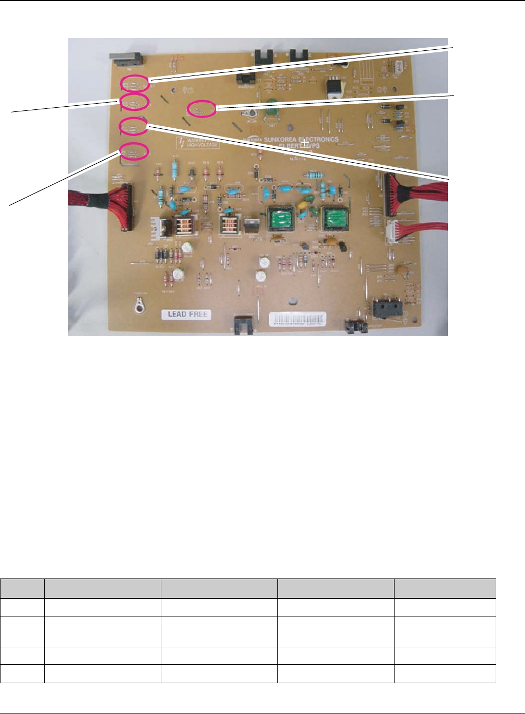
General Procedures and Information
6-26 5/08 Phaser 3435
Figure 2
SMPS (Switching Mode Power Supply)
It is the power source of entire system. It is assembled by an independent module, so it is possible
to use for common use. It is mounted at the side of the machine. It is consisted of the SMPS part,
which supplies the DC power for driving the system, and the AC heater control part, which sup-
plies the power to fuser. SMPS has two output channels. Which are +5V and +24V.
• AC Input
-Input Rated Voltage: AC 220V ~ 240V AC 110V ~ 127V
-Input Voltage fluctuating range: AC 198V ~ 264V AC 99V ~ 135V
-Rated Frequency: 50/60 Hz
-Frequency Fluctuating range: 47 ~ 63 Hz
-Input Current: Under 4.0Arms / 2.0Arms (But, the status when e-coil is off or rated voltage is
inputted/outputted)
Table 1: Rated output power
NO ITEM CH1 CH2 Remark
1 Channel Name +5V +24.0V
2 Connector Pin CON 35V PIN: 11,13,15
GND PIN: 12,14,16 CON 324V PIN:3,5,7,9
GND PIN:4,6,8,10
3 Rated Output +5V 5%(4.75 5.25V) +24V 10%(21.6 26.4V)
4 Max. Output Current 3 A 4.4 A
SUPPLY
-630 +/-3%
OPC
-130 +/-15.4%
DEV
-430 +/-3%
MHV
-1350 +/-3%
THV
+1300 +/-3%
-1200 +/-3%
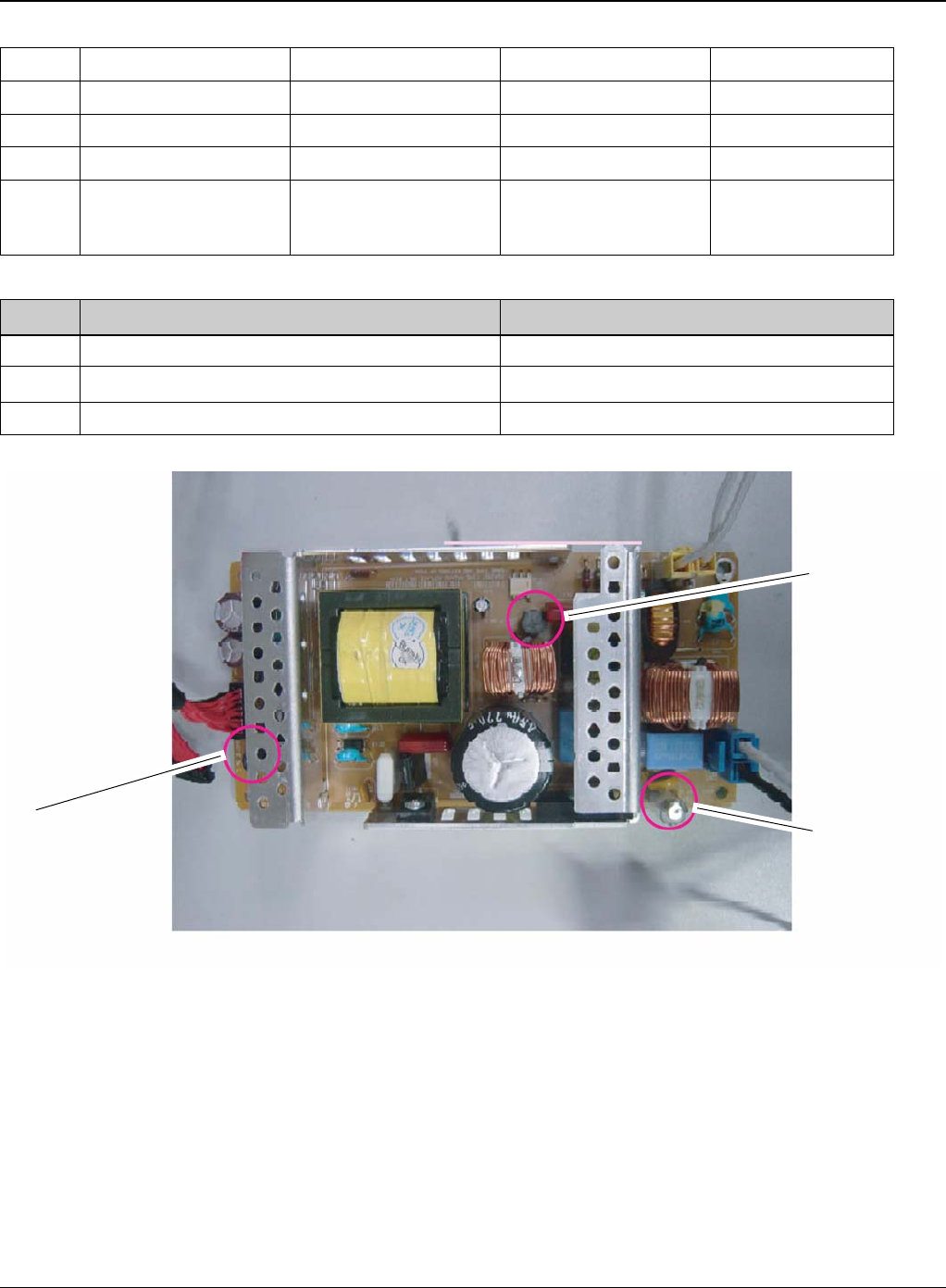
General Procedures and Information
Phaser 3435 5/08 6-27
Table 2: Consumption power
Figure 3
• Length of Power Cord: 1830 50mm
• Power Switch: Use
•Feature
-Insulating Resistance: 100 or more (at DC 500V)
-Withstanding Voltage: Must be no problem within 1 min.(at 1000V-LV model / 1500Vac-HV
model,10mA)
-Leaking Current: under 3.5mA
-Running Current: under 40A PEAK (AT 25, COLD START) under 60A PEAK (In other condi-
5 Peak Loading Current 3.6 A 5.3 A 1ms
6 Ripple Noise Voltage 100mVp-p Under 500mVp-p
7 Maximum output 15W 105.6W
8 Peak output 18W 127.2W 1ms
9 Protection for loading
shortage and overflow-
ing current
Shut down or Fuse Pro-
tection Shut down or Output
Voltage Drop
NO ITEM System
1 Stand-By Less than 130W
2 Printing Less than 400W
3 Sleep-Mode Less than 11W
Fuse 5V Fuse 5V
Fuse 24V

General Procedures and Information
6-28 5/08 Phaser 3435
tions)
-Rising Time: within 2Sec
-Falling Time: over 20ms
-Surge: Bi-Wave 3kV Normal, 6KV - Common
• Environment Condition
- Operating temperature range: 0 40
- Maintaining temperature range: -25 85
- Preserving Humidity Condition: 30% 90% RH
-Operating atmospheric pressure range: 1atm
• EMI Requirement: CISPR,FCC, CE, MIC, C-Tick,
• Safety Requirement:IEC950 UL1950, CSA950, C-UL,NOM, TUV, Semko, Nemko, iK, CB,
CCC(CCIB), GOST, EPA, Power Save
Fuser AC Power Control
Fuser (e-coil) gets heat from AC power. The AV power controls the switch with the Triac, a sem-
iconductor switch. The ON/OFF control is operated when the gate of the Triac is turned on/off by
Phototriac (insulting part). In other words, the AC control part is passive circuit, so it turns the heat-
er on/off with taking signal from engine control part. When the HEATER ON signal is turned on at
engine, the LED of PC501 (Photo Triac) takes the voltage and flashes.From the flashing light, the
Triac part (light receiving part) takes the voltage, and the voltage is supplied to the gate of Triac
and flows into the Triac. As a result, the AC current flows in the e-coil, and heat is occurred. On
the other hand, when the signal is off, the PC501 is off, the voltage is cut off at the gate of Triac,
the Triac becomes off, and then the e-coil is turned off.
• Triac (Q501) feature: 24A-LV model / 16A-HV model, 600V SWITCHING
• Phototriac Coupler (PC501)
-Turn On If Current: 15mA ~ 50mA(Design: 16mA)
-High Repetitive Peak Off State Voltage: Min 600V
Engine F/W
Control Algorithm
• Feeding
If feeding from a cassette, the drive of the pickup roller is controlled by controlling the sole-
noid. The on/off of the solenoid is controlled by controlling the general output port or the
external output port. While paper moves, occurrence of Jam is judged as below.

General Procedures and Information
Phaser 3435 5/08 6-29
Table 4:
•Transfer
The charging voltage, developing voltage and the transfer voltage are controlled by PWM
(Pulse Width Modulation). The each output voltage is changeable due to the PWM duty.
The transfer voltage admitted when the paper passes the transfer roller is decided by
environment recognition. The resistance value of the transfer roller is changed due to the
surrounding environment or the environment of the machine, and the voltage value, which
changes due to the environments, is changed through AD converter. The voltage value for
impressing to the transfer roller is decided by the changed value.
•Fusing
The temperature change of the heat rollers surface is changed to the resistance value
through the thermistor. By converting the voltage value, which impressed to the resis-
tance, to the digital value through the AD converter, the temperature is decided. The AC
power is controller by comparing the target temperature to the value from the thermistor.If
the value from the thermistor is out of controlling range while controlling the fusing, the
error stated in the below table occurs.
• Open Heat Error
When the engine operates the warm-up process, if the temperature of the fixing unit is not
higher than a specified temperature, the engine defines Open Heat Error. When this error
is broken out, the engine stops all functions and keeps the error state. Also, the engine
informs the error status of the main system. And then the error message is displayed at
LCD window or LED informing the error status of the user.
• Low Heat Error
When the engine is at stand-by, printing or warm-up mode, if the temperature of the fixing
unit is lower than the specified temperature at each state and the lower temperature state
is maintained during the specified time, the engine defines Low Heat Error. When this
error is broken out, the engine stops all functions and keeps it at the error state. Also the
ITEM Description
JAM 0 - After picking up, paper cannot be entered due to paper is not fed.
- After picking up, paper entered but it cannot reach to the feed sensor in certain time due to slip,
etc.
-After picking up, if the feed sensor is not on, re-pick up. After re-picking up, if the feed sensor is
not on after certain time, it is JAM 0.
*It is a status that the leading edge of the paper doesn’t pass the feed sensor.
-Even though the paper reaches to the feed sensor, the feed sensor doesn’t be ON.
*It is a status that the leading edge of the paper already passes the feed sensor.
JAM 1 -After the leading edge of the paper passes the feed sensor, the trailing edge of the paper can-
not pass the feed sensor after a certain time. (The feed sensor cannot be OFF)
- After the leading edge of the paper passes the feed sensor, the paper cannot reach the exit
sensor after certain time. (The exit sensor cannot be ON)
*The paper exists between the feed sensor and the exit sensor.
JAM 2 -After the trailing edge of the paper passes the feed sensor, the paper cannot pass the exit sen-
sor after certain time.

General Procedures and Information
6-30 5/08 Phaser 3435
engine informs the error status of the main system. And then the error message is dis-
played at LCD window or LED informing the error status of the user.
• Over Heat Error
For overall engine state, if the temperature of the fixing unit is higher than the specified
temperature and the temperature state is kept during the specified time, the engine
defines Over Heat Error. When this error is broken out, the engine stops all functions and
keeps it at the error state. Also, the engine informs the error status of the main system.
And then the error message is displayed at LCD window or LED to inform the error status
of the user.
* To recover the heat error: The heat error recovery is operated automatically when the
error is only caused by Low Heat Error, not the Heat Errors in Warm-up state and the Over
Heat Error. If an error happens, then the engine memorizes a present temperature. In
case of Low Heat Error, the maximum heat is supplied to the fixing unit. When a specified
time is elapsed, the engine detects the temperature again. If the present temperature is
higher than the memorized temperature, the error is recovered. In case of Over Heat
Error, no heat is supplied to the fixing unit. When a specified time is elapsed, the engine
detects a present temperature again. If the present temperature is a specified degree
lower than the memorized temperature, the error is recovered.
•LSU
LSU receives the image data from PVC or HPVC and make the latent image on OPC sur-
face.
It uses the dual beam, LD1 and LD2. But the control method of them is the same.
Just in comparison with the single beam, the dual beam has the half of LSUs frequency.
->The frequency of the dual beam = the frequency of the single beam /2.
The errors related to LSU are as follows:
* By LReady: When the printing is started, the engine drives the polygon motor of LSU.
After the specified time is elapsed, if the motor is not in a ready status, the engine detects
the error that the polygon motor is not in a ready status. If this error happens, the engine
stops all functions and keeps it at the error state. Also, the engine informs the error status
of the main system and the error message is displayed at LCD window to inform the error
status of the user.
* By Hsync: When the polygon motor is ready, the LSU sends out the signal called Hsync
and used to synchronize with each image line. So, if the engine does not detect consecu-
tively the signal for a fixed time, it defines the Hsync Error. If this error happens, the
engine stops all functions and keeps it at the error state. Also, the engine informs the error
status of the main system and then the error message is displayed at LCD window to
inform the error status of the user.
LSU Error Recovery: If the LReady or Hsync error happens, the paper exits out before
hand. The engine mode is changed to recovery mode and the engine informs the main
system of the engine mode. And the engine checks the LSU error. If the error doesn’t hap-
pen, the printing job will be proceeding.
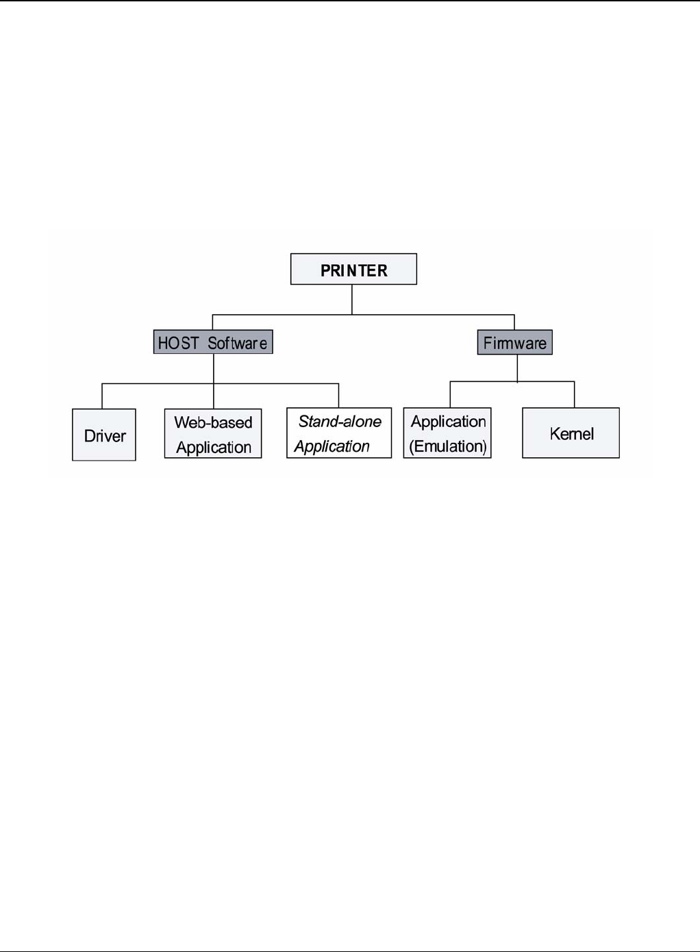
General Procedures and Information
Phaser 3435 5/08 6-31
S/W Descriptions
Overview
The software of the system is constructed with
1. Host Software part that the application software operated in Window and Web Environment,
and
2. Firmware parts that is a Embedded software controls printing job.
Architecture
Figure 5
Host Software is made up of
1. Graphic User Interface that offers the various editing functions to user in Host,
2. Driver that translates the received document to a Printing Command language which printer
can understand and transfers data to spooler,
3. Stand-alone Application that offers the various printing application, DMS (Document Manage-
ment System), RCP (Remote Control Panel), Printer Status Monitor, Network Management in
Window system,
4. Web-based-Application that offers the same functions as Stand-alone Application and RDC
(Remote Diagnosis Control) in Web environment.
Firmware is made up of
1. Application (Emulation) that is a interpreter translate data received from Host to a printing lan-
guage (PCL, PS, GDI, etc.) to be able to make the user to take same output as originally one
what composed in Host.
2. Kernel that control and management the whole procedure include of Control flow and Printing
Job before transfer to Engine system.
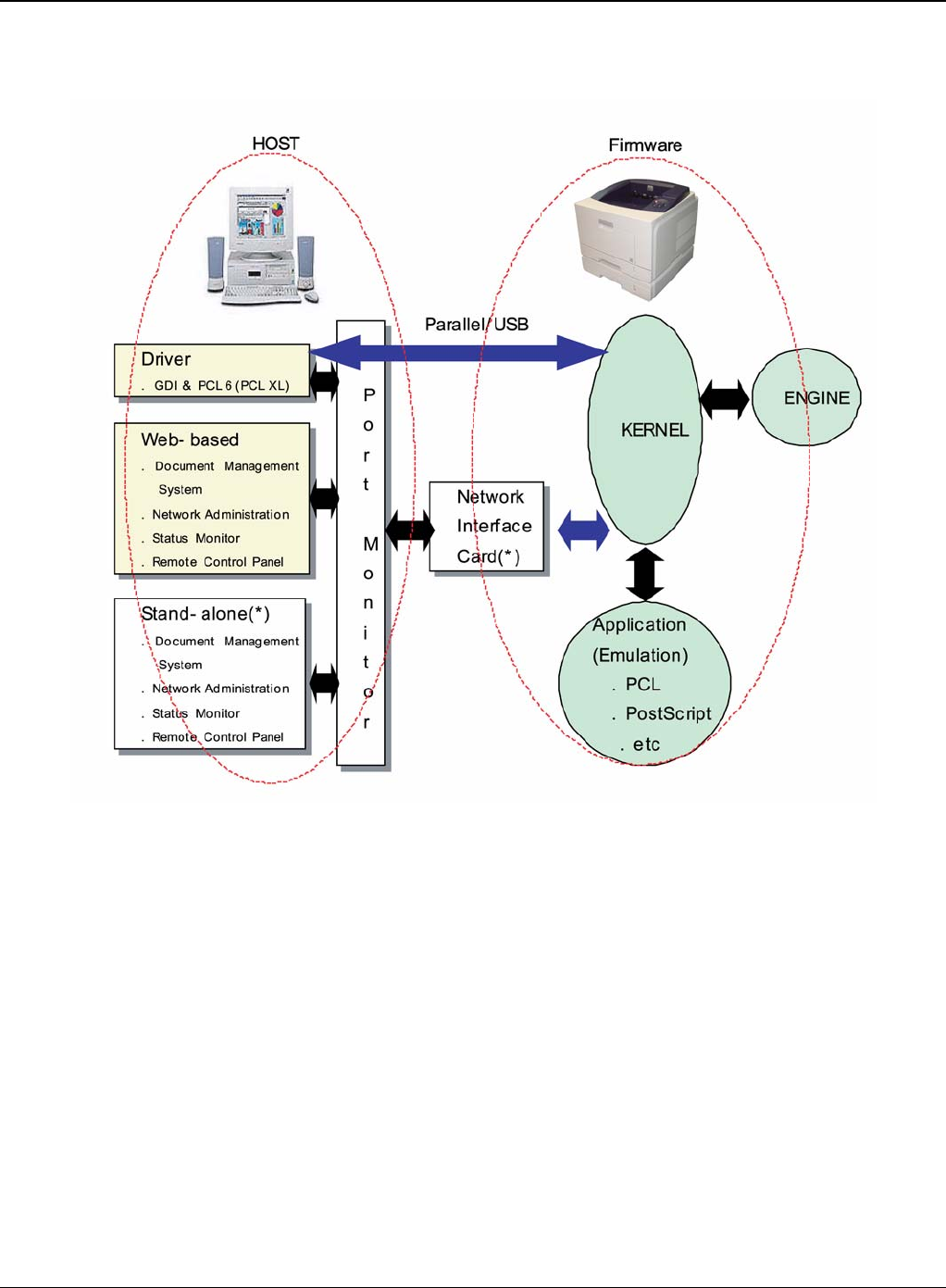
General Procedures and Information
6-32 5/08 Phaser 3435
Data and Control Flow
Figure 6
The above Block Diagram is explained that:
Host Side is made up of
1. Driver that is Windows application software translate printed data to one of printer language
and create spooler file.
2. Web-based Application that offer a various printer additional functions, management of print-
ing job, printer administration, Status monitor to monitoring the printer status by real time in
Web, independent environment on OS.
3. Stand-alone Application that is a similar Window software as same as above 2.
4. Port Monitor that manages the network communication between spooler and Network Inter-
face Card, or various additional application and Network Interface Card, (this is, at first, make
communication logical port, manage the data, transfer them from spooler to network port, and
offer the result of printing).

General Procedures and Information
Phaser 3435 5/08 6-33
Firmware Side is made up of
1. Network Interface Card is that relay the communication between Host and kernel using vari-
ous network protocol,
2. Kernel is that manages the flow control of emulation procedure, receiving data from Host or
Network card and printing with engine & rendering job,
3. Emulation is that interprets the various output data from selected emulation,
4. Engine is that prints rendered bit-map data to paper with required size and type by Kernel.
And then, for Job Spooling function for Multi-User, Multi-Printing that is occurred in Network print-
ing and various additional printing functions, this Kernel use max. 10 Queuing systems in a mem-
ory.
In Printing, the two procedures are
1. Case of using USB Port
• After user start to print the wanted document to PCL string or compressed GDI bit-map
data, Driver translate the all graphic data of it and send data to host spooler. And then the
spooler sends the data stream to the printer via USB port.
• Kernel receives this data from Host, and then select emulation fit to data and start
selected one. After emulation job end, Kernel sends the output bit-map data to Engine
using Printer Video Controller (by clock type for LSU).
• Engine print the received data to required paper with the sequential developing process.
2. Case of using Network Interface Card
• After user start to print the wanted document to PCL string or compressed GDI bit-map
data, Driver translate the all graphic data of it and send data to host spooler.
• If so, Port monitor managing network port receives data from spooler and sends a data
stream to the Network Interface Card.
• Network interface card receives it and send to Kernel part,
• Kernel receives this data from Host, and then select emulation fit to data and start
selected one. After emulation job end, Kernel sends the output bit-map data to Engine
using Printer Video Controller (by clock type for LSU).
• Engine print the received data to required paper with the sequential developing process.
The additional printing function are realized in
(1) Web environment
(2) Window environment.
On addition, Kernel informs a status of printing status and printer status to user made printing job
with the Status Monitor.

General Procedures and Information
6-34 5/08 Phaser 3435
GP 4 Screws Used in the Printer
No. Location Description & Specification QT’y
S1(BH
Short) SCREW-
MACHINE;BH,+,M3,L6,ZPC(WHT),SWRCH18
A,-,
3
SCREW-
MACHINE;BH,+,M3,L6,ZPC(WHT),SWRCH18
A,-,
2
S2(PH
Long) SHIELD+PARRALLEL
PORT SCREW-MACHINE;PH,+,M3,L8,NI
PLT,SWRCH18A,FP, 2
S3(WH
Long) SCREW-TAPPING;PWH,+,-
,2,M3,L8,ZPC(BLK),SWRCH18A, 4
SCREW-TAPPING;PWH,+,-
,2,M3,L8,ZPC(BLK),SWRCH18A, 1
S4(WH
Long) COVER MIDDLE+FRAME
BASE SCREW-TAPTITE;PWH,+,B,M3,L10,NI
PLT,SWRCH18A 6
COVER REAR SCREW-TAPTITE;PWH,+,B,M3,L10,NI
PLT,SWRCH18A 4
COVER SIDE L SCREW-TAPTITE;PWH,+,B,M3,L10,NI
PLT,SWRCH18A 1
COVER SIDE R SCREW-TAPTITE;PWH,+,B,M3,L10,NI
PLT,SWRCH18A 1
COVER TOP SCREW-TAPTITE;PWH,+,B,M3,L10,NI
PLT,SWRCH18A 4
DUP DRIVE ASS'Y+FRAME
BASE SCREW-TAPTITE;PWH,+,B,M3,L10,NI
PLT,SWRCH18A 3
DUP FAN+FRAME BASE SCREW-TAPTITE;PWH,+,B,M3,L10,NI
PLT,SWRCH18A 1
MAIN DRIVE
ASS'Y+FRAME BASE SCREW-TAPTITE;PWH,+,B,M3,L10,NI
PLT,SWRCH18A 6
SHIELD CONTROL-
LER+FRAME BASE SCREW-TAPTITE;PWH,+,B,M3,L10,NI
PLT,SWRCH18A 3
SHIELD SMPS+FRAME
BASE SCREW-TAPTITE;PWH,+,B,M3,L10,NI
PLT,SWRCH18A 3
Frame Base+Fuser SCREW-TAPTITE;PWH,+,B,M3,L10,NI
PLT,SWRCH18A 4
frame assy SCREW-TAPTITE;PWH,+,B,M3,L10,NI
PLT,SWRCH18A 33
SCREW-TAPTITE;PWH,+,B,M3,L10,NI
PLT,SWRCH18A 1
FRAME MP+BRACKET
FEED SCREW-TAPTITE;PWH,+,B,M3,L10,NI
PLT,SWRCH18A 2
FRAME MP+HOLDER IDLE
FEED SCREW-TAPTITE;PWH,+,B,M3,L10,NI
PLT,SWRCH18A 2
FRAME MP+SOLENOID SCREW-TAPTITE;PWH,+,B,M3,L10,NI
PLT,SWRCH18A 1

General Procedures and Information
Phaser 3435 5/08 6-35
SCREW-TAPTITE;PWH,+,B,M3,L10,NI
PLT,SWRCH18A 3
Frame Dup+Bracket Align
Dup SCREW-TAPTITE;PWH,+,B,M3,L10,NI
PLT,SWRCH18A 2
Frame Dup+Guide Upper
Dup SCREW-TAPTITE;PWH,+,B,M3,L10,NI
PLT,SWRCH18A 4
COVER FRONT+HOLDER
LOCKER SCREW-TAPTITE;PWH,+,B,M3,L10,NI
PLT,SWRCH18A 2
COVER MIDDLE+CAP SUB
ACTUATOR SCREW-TAPTITE;PWH,+,B,M3,L10,NI
PLT,SWRCH18A 1
PBA+COVER KEY
MENU_LCD SCREW-TAPTITE;PWH,+,B,M3,L10,NI
PLT,SWRCH18A 4
COVER CAS-
SETTE+FRAME CASSETTE SCREW-TAPTITE;PWH,+,B,M3,L10,NI
PLT,SWRCH18A 2
S5(WH
Long) BLDC MOTOR+BRKT
MOTOR SCREW-TAPTITE;PWH,+,-
,S,M4,L8,ZPC(WHT),SWRCH18A, 4
S6(BH
Short) PLATE KNOCKUP+CAM
KNOCKUP SCREW-TAPTITE;BH,+,-
,B,M3,L6,ZPC(WHT),SWRCH18A, 1
S7(WH
Short) TRAY ASF INPUT
UPPER+GEAR PINION SCREW-TAPTITE;PWH,+,-
,B,M3,L6,ZPC(WHT),SWRCH18A, 1
SCREW-TAPTITE;PWH,+,-
,B,M3,L6,ZPC(WHT),SWRCH18A, 2
LCD+COVER KEY
MENU_LCD SCREW-TAPTITE;PWH,+,-
,B,M3,L6,ZPC(WHT),SWRCH18A, 2
GEAR PINION+FRAME
CASSETTE SCREW-TAPTITE;PWH,+,-
,B,M3,L6,ZPC(WHT),SWRCH18A, 1
S8(BH
Short) BRKT MOTOR+BRKT GEAR SCREW-TAPTITE;BH,+,-
,S,M3,L6,ZPC(WHT),SWRCH18A, 4
SHIELD CONTROL-
LER+PBA SCREW-TAPTITE;BH,+,-
,S,M3,L6,ZPC(WHT),SWRCH18A, 3
SHIELD SMPS+SMPS SCREW-TAPTITE;BH,+,-
,S,M3,L6,ZPC(WHT),SWRCH18A, 4
HVPS+SHIELD HVPS SCREW-TAPTITE;BH,+,-
,S,M3,L6,ZPC(WHT),SWRCH18A, 3
SCREW-TAPTITE;BH,+,-
,S,M3,L6,ZPC(WHT),SWRCH18A, 2
SCREW-TAPTITE;BH,+,-
,S,M3,L6,ZPC(WHT),SWRCH18A, 4
S9(BH
Short) SCREW-TAPTITE;BH,+,-
,B,M3,L8,ZPC(BLK),SWRCH18A, 8
SCREW-TAPTITE;BH,+,-
,B,M3,L8,ZPC(BLK),SWRCH18A, 5
SCREW-TAPTITE;BH,+,-
,B,M3,L8,ZPC(BLK),SWRCH18A, 10
S10(BH
Long) SHIELD SMPS+EARTH
HARNESS SCREW-TAPTITE;BH,+,-
,S,M4,L6,ZPC(WHT),SWRCH18A, 1

General Procedures and Information
6-36 5/08 Phaser 3435
S11(BH
Short) LSU+FRAME BASE SCREW-TAPTITE;BH,+,B,M4,L10,NI
PLT,SWRCH18A 4
S12(BH
Long) SCREW-TAP-
TITE;PH,+,WSP,B,M3,L10,ZPC(WHT),SWRCH
18A,
3

General Procedures and Information
Phaser 3435 5/08 6-37
GP 5 System Set-up
This chapter provides step by step information on setting up the printer.This chapter includes:
• Using control panel menus
• Menu overview
• Printing a demo page
• Changing the display language
• Using toner save mode
Using control panel menus
A number of menus are available to make it easy for to change the printer settings. The diagram
shows the menus and all of the menu items available in each menu.
Accessing control panel menus
The printer can be controlled from the control panel. The control panel menus can be set while the
printer is in use.
1. Press Menu until the valid menu appears on the bottom line of the display and press OK.
2. Press the Scroll buttons until the desired menu item appears and press OK.
3. If the menu item has sub menus, repeat step 2.
4. Press the Scroll buttons to access the desired setting option or the required value.
5. Press OK to save the selection. An asterisk (*) appears next to the selection on the display,
indicating that it is now the default.
6. Press Stop to return to Standby mode. After 60 seconds of inactivity (no key being pressed),
the printer automatically returns to Standby mode.
Menu overview
The control panel menus are used to configure the printer. The control panel provides access to
the following menus:
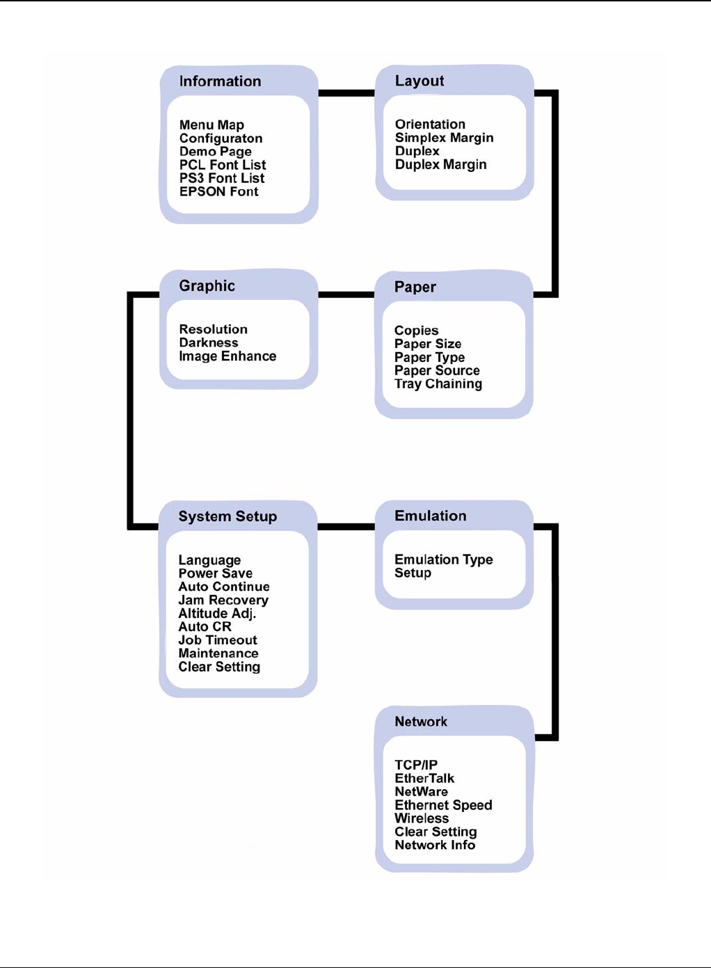
General Procedures and Information
6-38 5/08 Phaser 3435
Figure 1

General Procedures and Information
Phaser 3435 5/08 6-39
Basic Operation of Panel
Status” LED Description
Off Power Off / Sleep Mode (When data receive it’ll Wake-up)
Green On Ready status
Blink Blink Slowly: Data Comm. status Blink Fast: Printing status
Red On Error which needs user action (Toner Empty, Paper Jam, Paper Empty,
Cover Open etc.)
Blink Recoverable Error (Paper Mismatching, Manual printing in MP Tray)
Warning status Warning just like supplies exchange (Toner Low etc.)
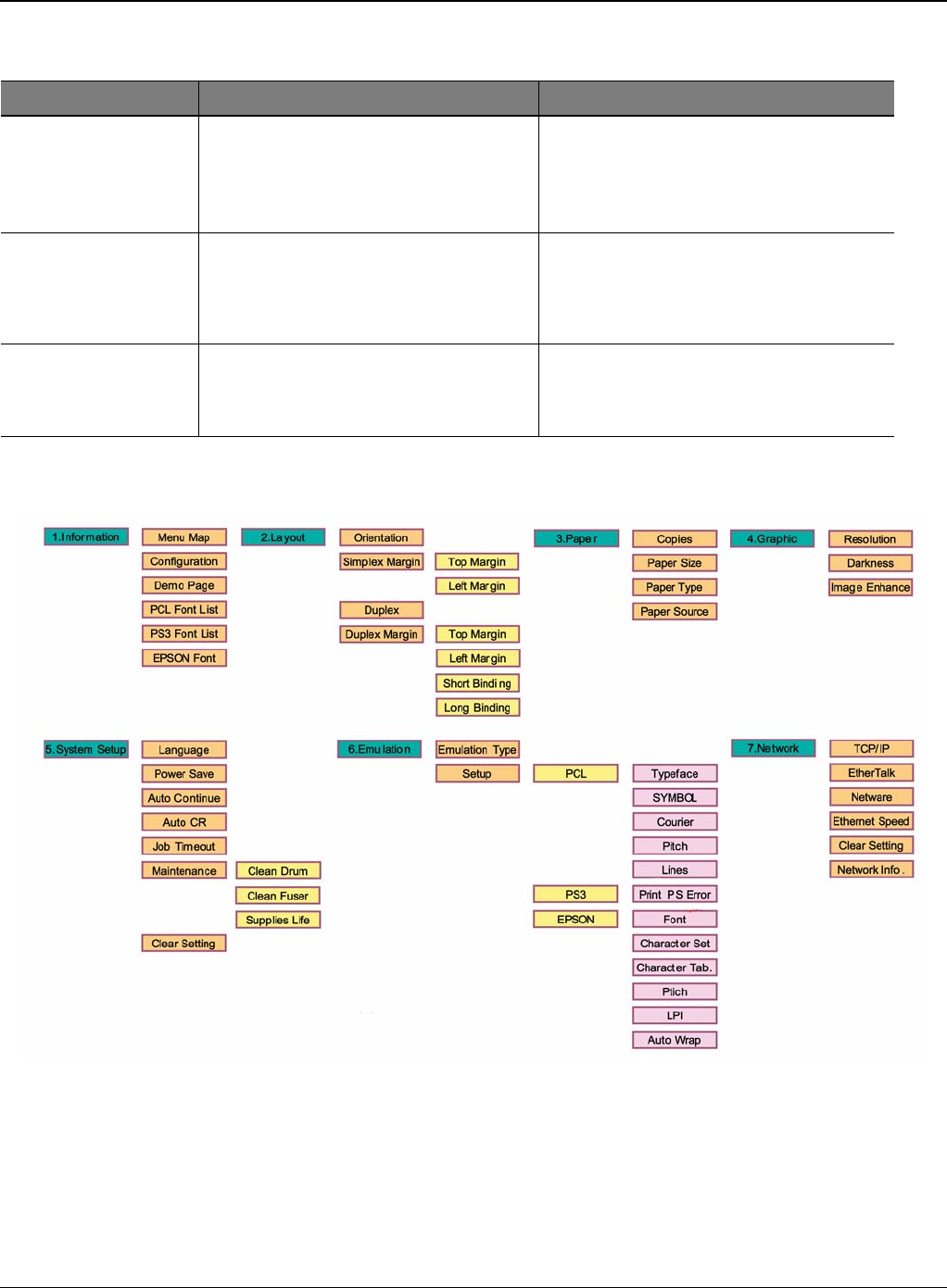
General Procedures and Information
6-40 5/08 Phaser 3435
Operation Map
Figure 2
Error Type Legacy models Error Platform model Error
Recoverable Error Error which can be recoverable Ex) Jam,
Paper Empty, etc. Error which doesn’t need any special user
actions Ex) Paper Mismatching, Manual
printing in MP Tray
Error Just like hardware error which can not be
fixed even if user does special action Ex)
Hsync Error, LSU Error, etc.
Including provider service error which
need some special user or provider action
sEx) Toner Empty, Paper Jam, Paper
Empty, Cover Open, etc.
Assert behaviour LCD model - It shows the task name and
the lines in LCD display LCD model - It shows the task name and
the lines in LCD display
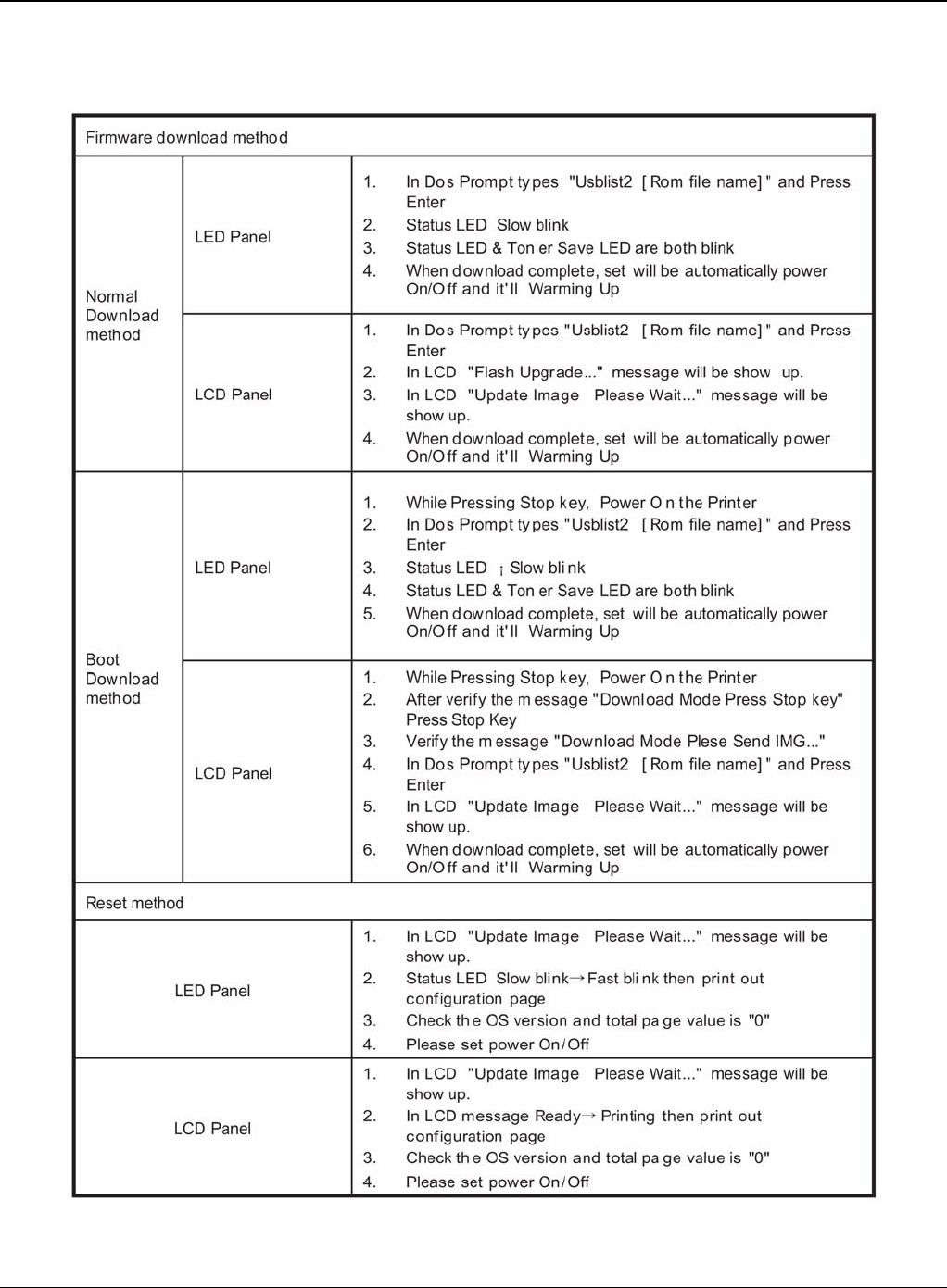
General Procedures and Information
Phaser 3435 5/08 6-41
GP 6 Download and Reset Firmware
Figure 1

General Procedures and Information
6-42 5/08 Phaser 3435
Firmware Upgrade Method
If the firmware needs to be upgraded, the firmware file and usbprn file are requested.
Check that the machine is in a "Ready" condition with the power on. The firmware can be upgrad-
ed by the following methods:
1. CentreWare Internet Services
2. USB Cable
• Save the firmware file to the laptop.
• Connect a USB cable between the port on the rear of the machine and the laptop.
• Drag and drop the upgrade file (.hd) onto the dltool.exe icon.
• A DOS command window will open and the upgrade file will be submitted to the machine.
• The upgrade should complete in approximately 5 minutes.
3. USB Cable Case (Save attached file at certain directory)
• Start Download Rom file "usbprbs b255_706.fls" on Dos Mode and push the enter key.
• Once Download is finished, "Reset Printer" is indicated on LCD window.
• Download finished, power ON/OFF.
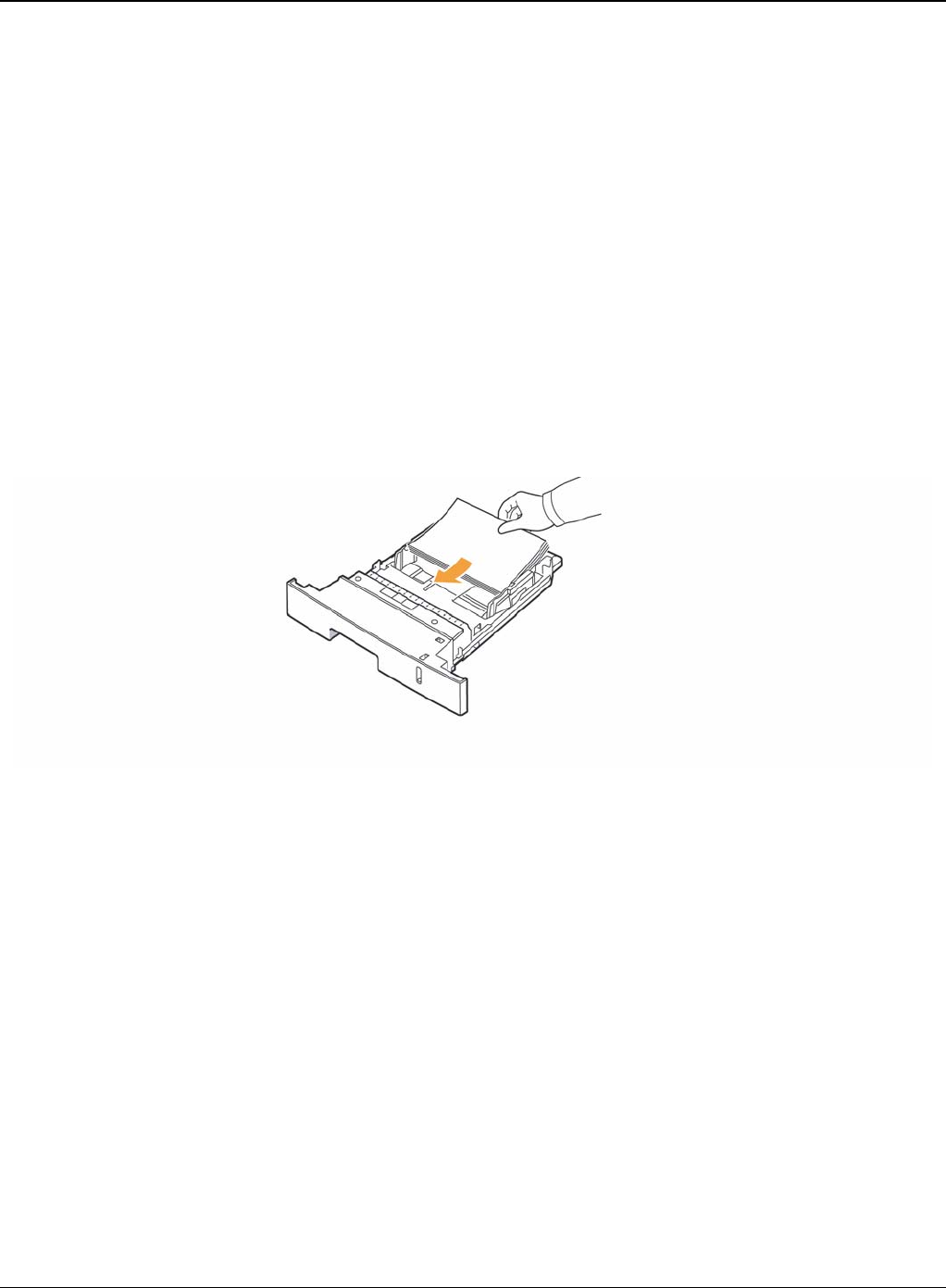
General Procedures and Information
Phaser 3435 5/08 6-43
GP 7 Tips for Avoiding Paper Jams
By selecting the correct media types, most paper jams can be avoided.
• Ensure that the adjustable guides are positioned correctly.
• Do not overload the tray. Ensure that the paper level is below the paper capacity mark on the
inside wall of the tray.
• Do not remove paper from the tray while your printer is printing.
• Flex, fan, and straighten paper before loading.
• Do not use creased, damp, or highly curled paper.
• Do not mix paper types in a tray.
• Use only recommended print media.
• Ensure that the recommended print side of print media is facing down in the tray, or facing up
in the multi-purpose tray.
• If paper jams occur frequently when you print on A5-sized paper: Load the paper into the tray
with the long edge facing the front of the tray.
Figure 1
In the printer properties window, set the page orientation to be rotated 90 degrees.

General Procedures and Information
6-44 5/08 Phaser 3435
GP 8 Acronyms and Abbreviations
The table below explains the abbreviations and acronyms used in this service manual. Where ab-
breviations or acronyms are used in the text please refer to this table.
Table 1: Acronyms and Abbreviations
Abbreviations Explanation
AP Access Point
AC Alternating Current
APC Auto Power Control
ASIC Application Specific Integrated Circuit
ASSY Assembly
BIOS Basic Input Output System
BLDC Brush-less Direct Current
CMOS Complementary Metal Oxide Semiconductor
CN Connector
CON Connector
CPU Central Processing Unit
dB decibel
dbA decibel A
dBM decibel milliwatt
DC Direct Current
DCU Diagnostic Control Unit
DPI Dot per Inch
DRAM Dynamic Random Access Memory
DVM Digital Voltmeter
ECP Enhanced Capability Port
EDC Embedded Diagnostic control
EEPROM Electronically Erasable Programmable Read Only Memory
EMI Electro Magnetic Interference
EP electrophotographic
EPP Enhanced Parallel Port
FPOT First Printout Time
F/W Firmware

General Procedures and Information
Phaser 3435 5/08 6-45
GDI Graphics device interface
GND Ground
HBP Host Based Printing
HDD Hard Disk Drive
H/H High temperature and high marshy place
HV High voltage
HVPS High voltage power supply
I/F Interface
I/O Input and Output
IC Integrated circuit
IDE Intelligent Drive electronics or Imbedded Drive Electronics
IEEE Institute of Electrical and Electronics Engineers. Inc
IPA Isopropy Alcohol
IPM Images Per Minute
LAN Local Area Network
lb pound(s)
LBP Laser Beam Printer
LCD Liquid Crystal Display
LED Light Emitting Diode
L/L Low temperature and low marshy place
LSU Laser Scanning Unit
MB megabyte
MHz megahertz
MPF Multi Purpose Feeder
NIC Network Interface Card
N/N Normal temperature and normal mashy place
NVRAM nonvolatile random access memory
OPC Organic Photo Conductor
OPE Operate Panel Equipment
PBA Printed Board Assembly
Table 1: Acronyms and Abbreviations
Abbreviations Explanation

General Procedures and Information
6-46 5/08 Phaser 3435
PCL Printer Command Language, Printer Control Language
PDL Page Description Language
PPM Page Per Minute
PPS Pulse Per Second
PS Post Script
PTL Pre-Transfer Lamp
PWM Pulse Width Modulation
Q-PID Quick Printer Initiating Device
Q’ty quantity
RAM Random Access Memory
ROM Read Only Memory
SCF Second Cassette Feeder
SMPS Switching Mode Power Supply
Spool Simultaneous Peripheral Operation Online
SW switch
Sync syncronous or syncronization
USB Universal Serial Bus
WECA Wireless Ethernet Compatibility Alliance
Table 1: Acronyms and Abbreviations
Abbreviations Explanation
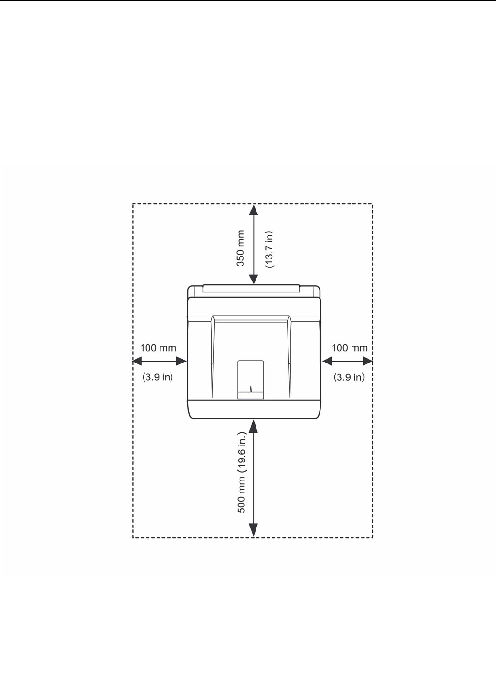
General Procedures and Information
Phaser 3435 5/08 6-47
GP 9 Selecting Printer Locations
Leave enough room to open the printer trays, covers, and allow for proper ventilation. (see dia-
gram below)
Provide the proper environment:
-A firm, level surface
-Away from the direct airflow of air conditioners, heaters, or ventilators
-Free of extreme fluctuations of temperature, sunlight, or humidity
-Clean, dry, and free of dust
Figure 1

General Procedures and Information
6-48 5/08 Phaser 3435
GP 10 Parts Life Cycle Maintenance Table
Print Cartridge
1. Print Cartridge Main Defects
- White Point, Black Point: White or Black point on printing image
- Image contamination: Dirty printing image
- Image Fainted: Entire Image is fainted and vertical white line emerge
- Black Line: Vertical black line emerge on printing image
2. Defect Symptoms
Supplies Life Cycle Condition Engine
Condition LCD
Indication
Customer
Panel
Manage Responding
Print Car-
tridge 4K: For Prod-
uct Toner Low Warning Ready Low
Toner - 10% Remains
10K: For Sale Toner Empty Warning Ready Toner - Initialized at toner
change
Toner unin-
stalled
Fuser 80K(page):
Simplex Exhausted No Indication No Indication Replaced at
Exhausted
Transfer
Roller 70K(page):
Simplex Exhausted No Indication No Indication Replaced at
Exhausted
PickUP Roller 150K(page):
Simplex Exhausted No Indication No Indication Replaced at
Exhausted
Symptoms Criterion Remarks
White, Black Point Clean Up OPC (10 times), if disappeared, no failure.
- If continuous, failure System Setup ->
Maintenance-> Clean Drum
Image contamina-
tion (Toner leak-
age)
Dirty printing image or contaminated reverse side
- Clean up OPC (10 times) and inside of machine with cloth, if
disappeared, no failure.
Image Fainted After shake cartridge right and left 5~6 times, if printing image is
not fainted, no failure. (Toner Exhausted)
Vertical Black Line Vertical thin line emerge, if cartridge is scratched.
- (Customer fault)
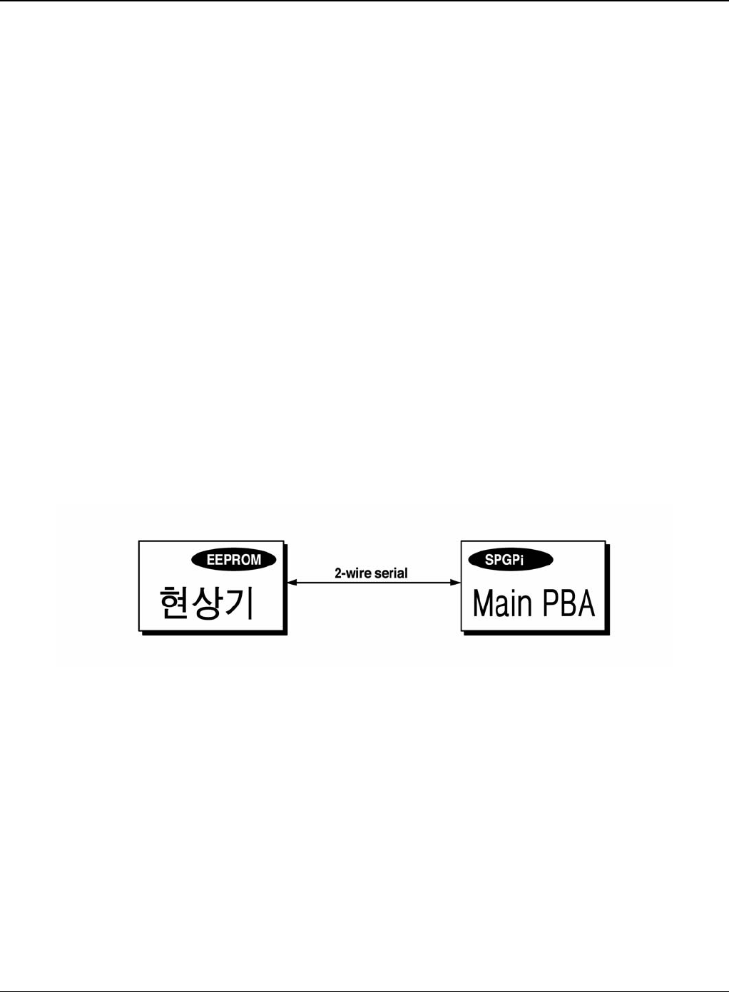
General Procedures and Information
Phaser 3435 5/08 6-49
GP 11 Print Cartridge Service
It is not guaranteed for the default caused by using other print cartridge other than the cartridge
supplied by Xerox or caused by non-licensed refill production.
Precautions on Safe Keeping of Print Cartridge
Excessive exposure to direct light more than a few minutes may cause damage to the cartridge.
Service for the Life of Print Cartridge
If the printed image is light due to the life of the toner, you can temporarily improve the print quality
by redistributing the toner (Shake the print cartridge), however, you should replace the print car-
tridge to solve the problem thoroughly.
Distinguish Function for Choice Cartridge
An EEPROM is mounted to a cartridge for distinguishing a choice print cartridge. Items written in
below are detected by checking up memory information. If the data of the EEPROM is broken, it
cannot be detected.
1. Detecting existence of a print cartridge: It detects whether a print cartridge is mounted or not.
2. Detecting a serial number of a print cartridge.
3. Detecting a print cartridge supplying company: If it is not original, it is not operated.
4. Detecting an OPC rotating counter: It detects the life span of an OPC drum.
Figure 1
Distinguish a refilled cartridge
1. Check whether One-way screw is damaged or not
2. Check the cartridge on configuration sheet (Print out the self-test configuration): Manufacture
date and serial number of print cartridge are different (permissible range: +/- 1).
Error message (LCD window) related in a toner sensor
It explains a message related in toner sensor in a LCD.
Invalid Toner
- Contents: It is displayed when a supplier is different between a print cartridge and a
machine. If this message is shown up, a printing process cannot operate.

General Procedures and Information
6-50 5/08 Phaser 3435
-Solution: Install a suitable print cartridge (the same supplier's). (A unique key has been
applied.)
Low Toner
- Contents: This message shows up when a message "remaining toner: 10%" is displayed in
a cartridge count information.
-Solution: It means that a toner in the print cartridge has been almost ended. Prepare the new
print cartridge.
Replace Cartridge
- Contents: It means the life span of a print cartridge (except a toner part) has been ended.
Even though a case that a toner is refilled, the rest of major parts have been ended, so entire
print cartridge might be replaced.
- Solution: If an Print Cartridge Life cycle Problem, in a worst case, a toner overflows and it
may cause a system fail. Therefore, recommend a user to replace a print cartridge.
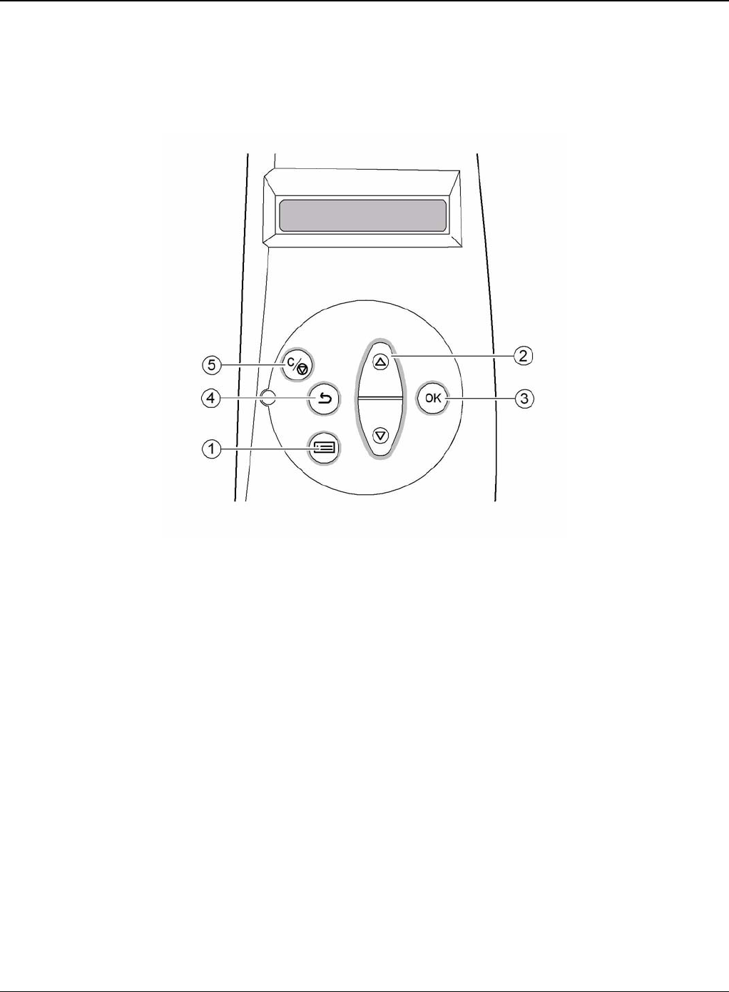
General Procedures and Information
Phaser 3435 5/08 6-51
GP 12 Control Panel
Control Panel Functions
1. Menu: Enters menu mode and scrolls through the available menus.
2. Scroll Buttons: Scroll through the options available in the selected menu and increase or
decrease values.
3. OK: Confirms the selection on the display.
4. Back: Sends you back to the upper menu level.
5. Stop: Stops an operation at any time.

General Procedures and Information
6-52 5/08 Phaser 3435
GP 13 Service Log
Service Log
Use the service log to record all service procedures. The service log is included at the end of the
manual.

Wiring Data
Phaser 3435 5/08 7-1
7 Wiring Data
WD 1 Block Diagram ................................................................................................................ 7-3
WD 2 Connection Diagram ....................................................................................................... 7-4

Wiring Data
7-2 5/08 Phaser 3435
This page is intentionally blank
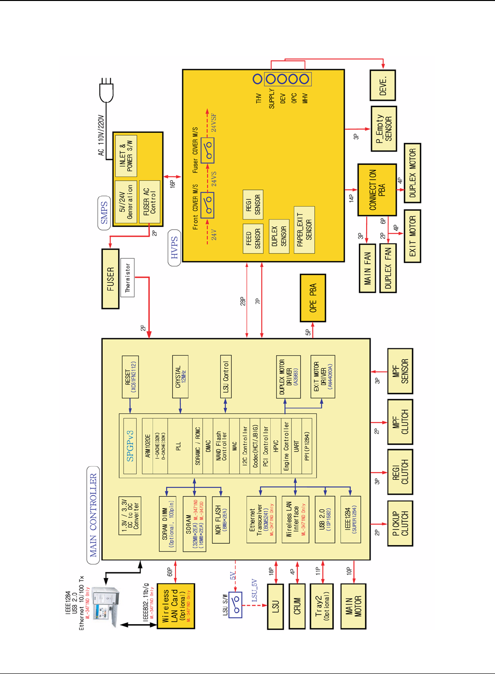
Wiring Data
Phaser 3435 5/08 7-3
WD 1 Block Diagram
Figure 1
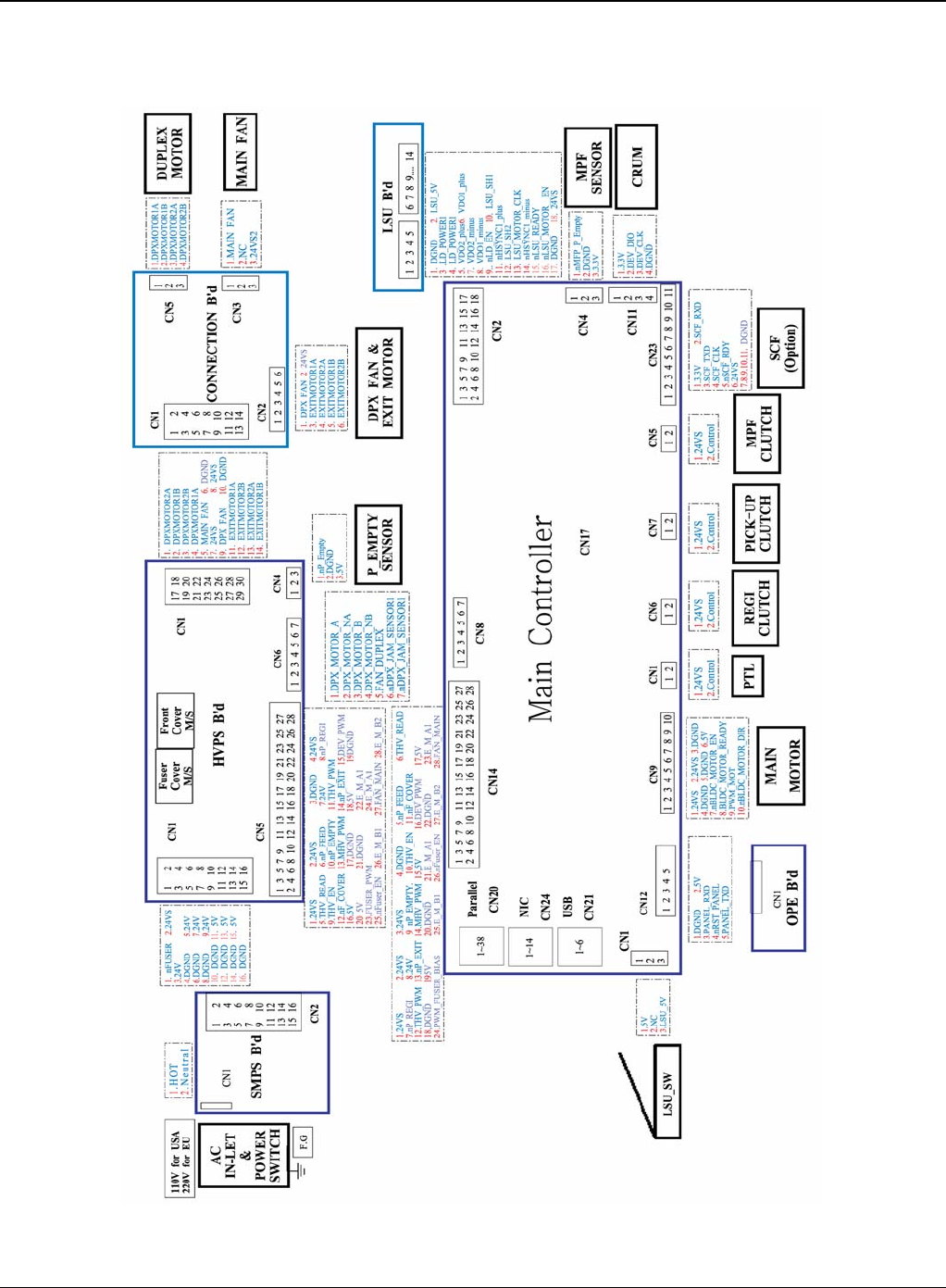
Wiring Data
7-4 5/08 Phaser 3435
WD 2 Connection Diagram
Figure 2
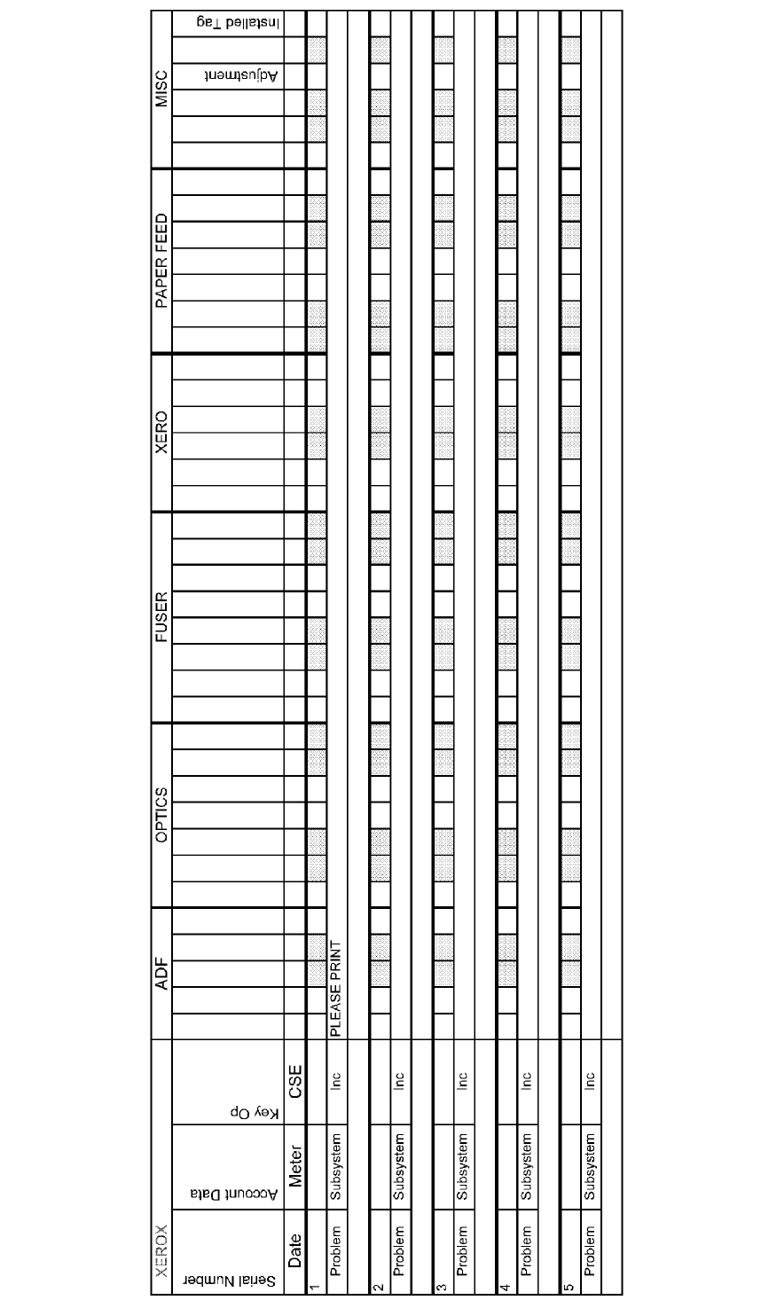
Form EH&S-700 Rev 2.0 (21 February 2008) North America Letter Format
EHS 700 - Health & Safety Incident Report Form
for Incidents Involving a Xerox Product
For incidents in Canada:
PIPEDA consent given YES NO EH&S Office Use ONLY
EH&S Incident Reference Number:
PIPEDA is the Canadian “Personal Information Protection and Electronic Documents Act.”
*Date Of Incident (mm / dd / yy):
Product Description
*Model No. or Product Name:
Product Serial Number:
Serial Number(s) of Accessory (ies):
Installation Date:
Total Copy Meter:
Date of last service maintenance:
List damaged and affected part(s) of the machine by description and part number:
*Description
Part Number
*Location of product and affected part(s):
Customer Identification
*Customer Name:
*Name of Customer Contact Person:
*Telephone:
*Address:
E-mail:
Fax:
Customer Service Engineer Identification
*Name (required for Xerox serviced equipment):
Employee:
E-mail:
Location:
*Phone (required for Xerox serviced equipment):
Individual Providing Notification
*Name: *Title: *Telephone Number:
*Organization:
E-Mail:
Mailing Address:
*Date Report Submitted:
* Required information is preceeded by asterisk, title shown in red, turquoise wash background

EHS 700 - Health & Safety Incident Report Form for Page 2
Incidents Involving a Xerox Product
Form EH&S-700 Rev 2.0 (21 February 2008) North America Letter Format
Details of Incident
*Description Of Incident: (Check all that apply)
Smoke
Describe quantity and duration of smoke:
Fire with open flames seen
Electric shock to operator or service representative
Physical injury/illness to operator or service representative
Describe:
Other, Describe:
MANDATORY DESCRIPTION (above): Provide a detailed description of all valid factors that may have
contributed to the incident. Hardware involved in the incident should be preserved and retained for further
investigation should investigation be deemed necessary by EH&S.
LIST INCIDENT DESCRIPTIONS AND SUPPORT DIAGRAMS/DATA INCLUDED OR ATTACHED:
*Any damage to customer property? No Yes Describe:
*Did external emergency response provider(s) such as fire department, ambulance, etc. respond?
No Yes Identify: (i.e., source, names of individuals)
Apparent cause of incident (identify part that is suspect to be responsible for the incident)
*Preliminary actions taken to mitigate incident:
Instructions: E-mail or fax both pages of this completed form to EH&S:
• For incidents in Xerox Europe and Developing Markets East
(Middle East, Africa, India, China, and Hong Kong)
Submit to Elaine Grange
e-mail: ehs-europe@xerox.com or fax: +44 (0) 1707 35 3914 [Intelnet 8*668 3914]
• For incidents in North America and Developing Markets West
(Brazil, Mexico, Latin America North and Latin America South,
Submit form to Doris Bush
e-mail: usa.xerox.ehs@xerox.com or fax 888-845-0908 [1-585-422-7918 / Intelnet 8*222-7734]
* Required information is preceeded by asterisk, title shown in red, turquoise wash background
XEROX EUROPE
PUBLICATION COMMENT SHEET
Please copy this master sheet and use it to help us to improve this publication. We would like you to tell us about
improvements to its accuracy, format and quality.
Please give specific references, i.e.: page numbers and figure numbers and attach marked up photocopies wher-
ever possible. If you have identified a solution please include your suggestions with your reply.
Please also answer the customer satisfaction question set.
When you have completed the PCS, send it by internal mail to the address below. You will receive an acknowl-
edgement and feedback on your comments. Please ensure that your name and CBU/District location code are
fully completed.
NAME:
JOB TITLE:
ENGINEER NUMBER:
CONTACT TELEPHONE NUMBER:
DATE:
OPERATING COMPANY:
CBU/DISTRICT LOCATION CODE:
PRODUCT AND PUBLICATION
TITLE: PUBLICATION REVISION
DATE: SOFTWARE REVISION LEVEL:
PAGE NUMBER: COMMENT
Please submit a marked-up photocopy of the relevant pages
CUSTOMER SATISFACTION QUESTION SET
QUESTION NOT
APPLICABLE VERY
SATISFIED SATISFIED NEITHER
SATISFIED
NOR
DISSATISFIED
DISSATISFIED VERY
DISSATISFIED
DO YOU FIND THE MANUAL IS TECHNICALLY
ACCURATE?
DO YOU FIND THE FORMAT OF THE MANUAL EASY
TO USE?
WHAT IS YOUR OVERALL SATISFACTION LEVEL
WITH THE MANUAL
FOR OFFICE USE ONLY Global Knowledge & Language Services
Xerox Europe
Enterprise Centre
Bessemer Road
Welwyn Garden City
Hertfordshire AL7 1HE
England
Attention: Phil Hayes
RECEIVED DATE:
PCS. NUMBER:
MANAGER:
DUE DATE:
XEROX EUROPE