Introduction To Xilinx ISE Guide
xilinx_guide
User Manual:
Open the PDF directly: View PDF ![]() .
.
Page Count: 7
Introduction to Xilinx ISE
CS141 Spring 2019
Getting around in Xilinx ISE
Xilinx ISE (integrated synthesis environment) is an industry tool for developing and conguring FPGAs.
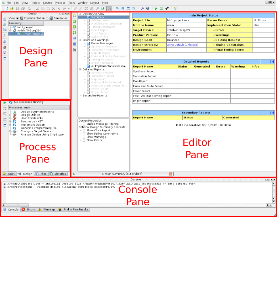
You can open a project le using File->Open Project. The above diagram shows the main areas of
the program.
The Design Pane organizes all of the conguration and source (HDL) les in your project. It has
two modes (radio box at the top) - Implementation and Simulation. Use the Simulation mode for
simulating, and the implementation mode for synthesizing your project (running on the FPGA). The
rest of the program will change options depending on which mode you are in.
The Process Pane will show the dierent operations you can do based on what is selected in the design
1
Introduction to Xilinx ISE CS141 Spring 2019
pane. This is where you can launch simulations or start synthesizing your design.
The Editor Pane is where you do most of your work, writing the Verilog HDL code that describes your
design, and viewing results about the synthesis process.
Verilog is a hardware description language (HDL), not a standard programming language. The impor-
tant thing to remember with Verilog is that every line you write creates actual digital hardware, and
does not execute sequentially. Read sections 1-5 of the cheatsheet (available on the course website)
and refer back to them as you complete the assignment.
To get started, launch Xilinx ISE, open the lab1.tar.gz, and double click the main.v le in the design
pane - this will open it up in the editor pane and allow you to edit it. The starting module here is
very bare - all it does is dene the inputs and outputs for the module.
Let’s try modifying the module so that the switch controls the LED in the opposite way (on in the
down position). Change the line to read
assign led = ~switch;
The “~” operator is the bitwise inverse operator; it assigns each bit in led to be the inverse of the
corresponding bit in switch (connects each bit of led to switch through a NOT gate). Let’s make sure
our change actually worked how we wanted it to, rst by simulation, and then through syntehsis.
Simulation
We’ll learn more about how to create good testbenches in future programming assignments, but for now,
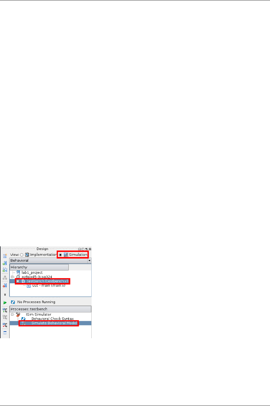
we just want to start the simulation environment and use it to verify our designs. Open the included
testbench.v le by going into the design pane, selecting Simulation mode, and double-clicking the
testbench.v le:
Make sure that testbench.v is highlighted, not main.v. The testbench has the necessary code to
run a simulation, while main.v just won’t do anything. This is a very common mistake, so if your
simulation isn’t doing anything, double check that you did this properly.
This starter testbench just runs through all of the possible input congurations for the switches and
prints the values of the switches and LEDs. It also checks to make sure you did part 1 correctly, but
it is up to you to write the remaining pieces of the testbench.
You can run the simulation by selecting both Simulation mode and the testbench.v le in the Design
Pane, and double clicking Simulate Behavioral Model in the Process Pane. This will launch isim,
Xilinx’s HDL simulation tool.
2
Introduction to Xilinx ISE CS141 Spring 2019
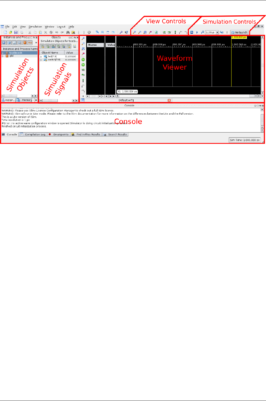
Isim will start out by running the simulation for 1us. By default, the inputs and outputs of your
module being tested (commonly referred to as the Unit Under Test, or UUT) will automatically show
up on the waveform viewer. To add more signals, make sure that the UUT is selected in the Simulation
Objects Pane. Every signal in main (only switch and led) will show up in the Simulation Signals pane.
You can drag and drop signals from the Simulation Signals pane to the Waveform Viewer. Only signals
added before the simulation starts will show.
In simulation, every net or wire can have one of four values - 0, 1, Z (unconnected), and X (undened).
Z’s will show up as blue in the waveform viewer, and X’s as red. This is a very easy way to catch
wiring issues!
If your simulation requires more than 1us of simulated time, you can continue the simulation by hitting
the play button in the Simulation Controls toolbar. If the testbench does not have a $nish directive,
this will continue for as long as you let it. This testbench does, but if you ever want to stop the
simulation, click the pause button. If you add more signals, you’ll need to rerun the simulation (press
the back arrow, followed by the play button). Lastly, the play button with an hourglass will step the
simulation forward by whatever time is the box next to it.
If you modify your HDL design, you need to tell Isim to recompile the simulation. You can do this
with the relaunch button. It is in general a good idea to relaunch the simulation every now and then
to make sure Isim is working with the latest design changes.
You should be able to see that at every time step, led is equal to the bitwise inverse of switch. This is
what we expected, so we can move on to synthesis.
For more information on Isim, check out the ocial tutorial here.
Creating a Xilinx Project
To create a new Xilinx Project, open ISE and entire File->New Project... to start the new project
wizard.
Enter the project’s name and location, and make sure the Top-level source type is set to “HDL”.
3

Introduction to Xilinx ISE CS141 Spring 2019
Modify the project settings as follows to make sure that the generated bitles work with the Atlys
board.
Hit Finish on the next window to complete your project.
Add New Source Files to a Project
Be sure to have a separate source le for each module you create. It might seem a bit verbose, but it
is both good HDL design practice and it can make debugging much easier.
1. Click on Project->New Source... to start the wizard
2. Select “Verilog Module” as the source type, and ll in the name of the module in the File Name
eld.
3. You can enter all of your ports on the next window, or do so manually once the source has been
generated.
4. Conrm the module’s details, and the le will be created.
The New Source wizard has been customized for this class to add the default_nettype none directive
in a way that does not break Xilinx’s built in Verilog modules. Without this directive you can get
many hard to nd bugs as Xilinx will automatically turn any typo into a new one bit wire. Please use
the New Source wizard to create new modules!
Add Existing Source Files to a Project
If you want to add an existing Verilog le to your project, copy it into the project directory, and use
Project->Add Source to let Xilinx know that it is there.
Create a Testbench From an Existing Source File
1. Click on Project->New Source... to start the wizard
2. Select “Verilog Test Fixture” as the source type, and ll in the name of the testbench
3. Pick the source le that you are buildiing a testbench for
4. Conrm the summary
This will generate a stub testbench. Fill it in with a test vector (see cheatsheet) and a checker if
necessary.
Programming the Board
Loading the bitle onto the FPGA
1. Connect the power supply to the board from an outlet
2. Connect the board’s PROG port to your computer via the USB cable
3. Switch the power on your board ON (you should see an LED turn on)
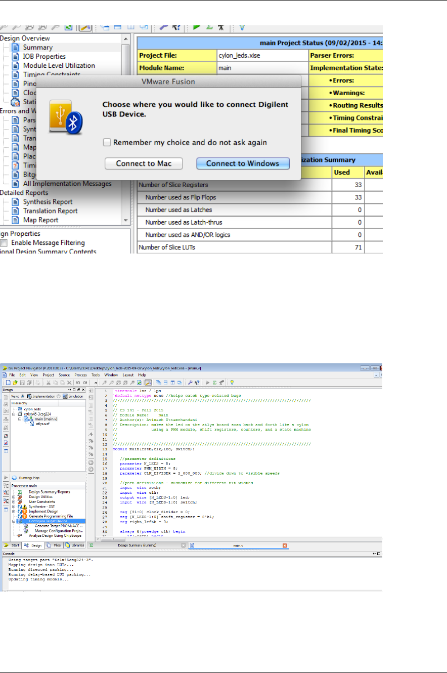
4. VMWare Fusion Only: you should see this message pop up:
4
Introduction to Xilinx ISE CS141 Spring 2019
Be sure to connect the board to Windows! If you don’t see this message contact a TF to
make sure that the virtual machine is seeing the connected board.
From Within ISE
1. Now we can congure the board to blink the LEDs in sequency like a Cylon. Double click the
“Congure Target Device” as shown:
2. You should see the LEDs blink in sequence. Congratulations, you have all of the tools you need
for the course. If you don’t, check out the other way of programming the board…
5
Introduction to Xilinx ISE CS141 Spring 2019
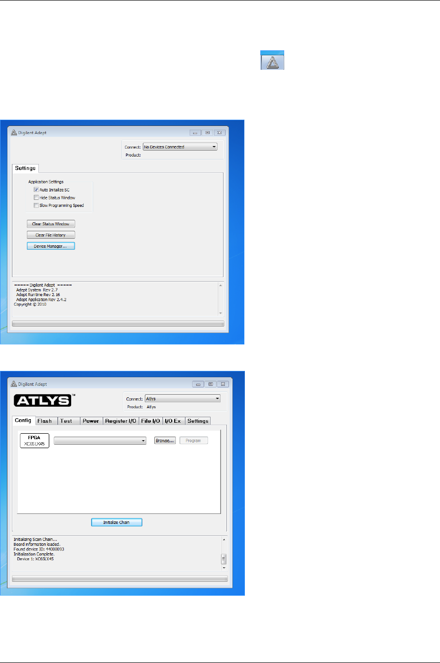
From Digilent’s Adept Tool
1. Launch the Digilent Adept Tool by clicking this icon:
2. Connect to the Atlys device (contact an instructor if you don’t see the device listed) by clicking
on the No Devices Connected drop down:
and selecting the Atlys board:
3. Click the Initialize Chain button.
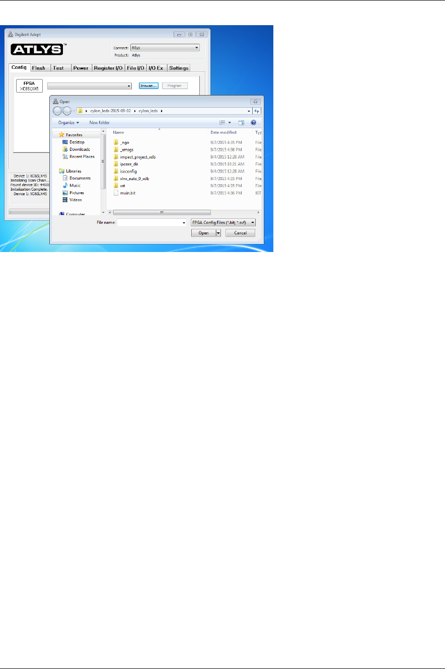
4. From the Cong tab, click on the Browse button and navigate to your project. Select the main.bit
le that’s there (this is the bitstream that congures the FPGA to our hardware).
6
Introduction to Xilinx ISE CS141 Spring 2019
5. Click the Program button. Your board should be programmed!
Modied by Zach Yedidia on January 28, 2019 7
