Vivado Design Suite User Guide: High Level Synthesis (UG902) Xilinx HLS Guide
User Manual:
Open the PDF directly: View PDF ![]() .
.
Page Count: 672 [warning: Documents this large are best viewed by clicking the View PDF Link!]
- Vivado Design Suite User Guide: High-Level Synthesis
- Revision History
- Table of Contents
- Ch. 1: High-Level Synthesis
- Introduction to C-Based FPGA Design
- Understanding Vivado HLS
- Using Vivado HLS
- Creating a New Synthesis Project
- Simulating the C Code
- Synthesizing the C Code
- Verifying the RTL is Correct
- Packaging the IP
- Archiving the Project
- Using the Command Prompt and Tcl Interface
- Improving Run Time and Capacity
- Design Examples and References
- Data Types for Efficient Hardware
- Managing Interfaces
- Interface Synthesis
- Specifying Manual Interface
- Using AXI4 Interfaces
- Managing Interfaces with SSI Technology Devices
- Optimizing the Design
- Clock, Reset, and RTL Output
- Optimizing for Throughput
- Optimizing for Latency
- Optimizing for Area
- Optimizing Logic
- Verifying the RTL
- Exporting the RTL Design
- Ch. 2: High-Level Synthesis C Libraries
- Introduction to the Vivado HLS C Libraries
- Arbitrary Precision Data Types Library
- HLS Stream Library
- HLS Math Library
- HLS Video Library
- HLS IP Libraries
- HLS Linear Algebra Library
- HLS DSP Library
- Ch. 3: High-Level Synthesis Coding Styles
- Introduction to Coding Styles
- Unsupported C Constructs
- C Test Bench
- Functions
- Loops
- Arrays
- Data Types
- C Builtin Functions
- Hardware Efficient C Code
- C++ Classes and Templates
- Assertions
- SystemC Synthesis
- Ch. 4: High-Level Synthesis Reference Guide
- Command Reference
- add_files
- close_project
- close_solution
- config_array_partition
- config_bind
- config_compile
- config_core
- config_dataflow
- config_interface
- config_rtl
- config_schedule
- config_unroll
- cosim_design
- create_clock
- csim_design
- csynth_design
- delete_project
- delete_solution
- export_design
- help
- list_core
- list_part
- open_project
- open_solution
- set_clock_uncertainty
- set_directive_allocation
- set_directive_array_map
- set_directive_array_partition
- set_directive_array_reshape
- set_directive_clock
- set_directive_dataflow
- set_directive_data_pack
- set_directive_dependence
- set_directive_expression_balance
- set_directive_function_instantiate
- set_directive_inline
- set_directive_interface
- set_directive_latency
- set_directive_loop_flatten
- set_directive_loop_merge
- set_directive_loop_tripcount
- set_directive_occurrence
- set_directive_pipeline
- set_directive_protocol
- set_directive_reset
- set_directive_resource
- set_directive_stream
- set_directive_top
- set_directive_unroll
- set_part
- set_top
- GUI Reference
- Interface Synthesis Reference
- AXI4-Lite Slave C Driver Reference
- XDut_Initialize
- XDut_CfgInitialize
- XDut_LookupConfig
- XDut_Release
- XDut_Start
- XDut_IsDone
- XDut_IsIdle
- XDut_IsReady
- XDut_Continue
- XDut_EnableAutoRestart
- XDut_DisableAutoRestart
- XDut_Set_ARG
- XDut_Set_ARG_vld
- XDut_Set_ARG_ack
- XDut_Get_ARG
- XDut_Get_ARG_vld
- XDut_Get_ARG_ack
- XDut_Get_ARG_BaseAddress
- XDut_Get_ARG_HighAddress
- XDut_Get_ARG_TotalBytes
- XDut_Get_ARG_BitWidth
- XDut_Get_ARG_Depth
- XDut_Write_ARG_Words
- XDut_Read_ARG_Words
- XDut_Write_ARG_Bytes
- XDut_Read_ARG_Bytes
- XDut_InterruptGlobalEnable
- XDut_InterruptGlobalDisable
- XDut_InterruptEnable
- XDut_InterruptDisable
- XDut_InterruptClear
- XDut_InterruptGetEnabled
- XDut_InterruptGetStatus
- HLS Video Functions Library
- OpenCV Interface Functions
- AXI4-Interface I/O Functions
- Video Processing Functions
- hls::AbsDiff
- hls::AddS
- hls::AddWeighted
- hls::And
- hls::Avg
- hls::AvgSdv
- hls::Cmp
- hls::CmpS
- hls::CornerHarris
- hls::CvtColor
- hls::Dilate
- hls::Duplicate
- hls::EqualizeHist
- hls::Erode
- hls::FASTX
- hls::Filter2D
- hls::FindStereoCorrespondenceBM
- hls::GaussianBlur
- hls::Harris
- hls::HoughLines2
- hls::Integral
- hls::InitUndistortRectifyMap
- hls::Max
- hls::MaxS
- hls::Mean
- hls::Merge
- hls::Min
- hls::MinMaxLoc
- hls::MinS
- hls::Mul
- hls::Not
- hls::PaintMask
- hls::PyrDown
- hls::PyrUp
- hls::Range
- hls::Remap
- hls::Reduce
- hls::Resize
- hls::Set
- hls::Scale
- hls::Sobel
- hls::Split
- hls::SubRS
- hls::SubS
- hls::Sum
- hls::Threshold
- hls::Zero
- HLS Linear Algebra Library Functions
- HLS DSP Library Functions
- C Arbitrary Precision Types
- Compiling [u]int#W Types
- Declaring/Defining [u]int#W Variables
- Initialization and Assignment from Constants (Literals)
- Support for console I/O (Printing)
- Expressions Involving [u]int#W types
- Bit-Level Operation: Support Function
- C++ Arbitrary Precision Types
- Compiling ap_[u]int<> Types
- Declaring/Defining ap_[u] Variables
- Initialization and Assignment from Constants (Literals)
- Support for Console I/O (Printing)
- Expressions Involving ap_[u]<> types
- Class Methods and Operators
- Other Class Methods, Operators, and Data Members
- C++ Arbitrary Precision Fixed-Point Types
- ap_[u]fixed Representation
- Quantization Modes
- Overflow Modes
- Compiling ap_[u]fixed<> Types
- Declaring and Defining ap_[u]fixed<> Variables
- Initialization and Assignment from Constants (Literals)
- Support for Console I/O (Printing)
- Expressions Involving ap_[u]fixed<> types
- Class Methods, Operators, and Data Members
- Comparison of SystemC and Vivado HLS Types
- Command Reference
- Appx. A: Additional Resources and Legal Notices

Vivado Design Suite
User Guide
High-Level Synthesis
UG902 (v2017.1) April 5, 2017

High-Level Synthesis 2
UG902 (v2017.1) April 5, 2017 www.xilinx.com
Revision History
The following table shows the revision history for this document.
Date Version Revision
04/05/2017 2017.1 Added new section HLS Math Library in Chapter 2.
Updated code examples in Pointers, apint_print(), Invert Bit, Dependencies with
Vivado HLS, and Cholesky Inverse and QR Inverse.
Removed -avg option for TRIPCOUNT throughout document.
Updated Specifying Arrays as Block RAM or FIFOs and set_directive_stream with
information about -depth.
Clarified C/RTL co-simulation halting conditions in Interface Synthesis
Requirements.
Updated Half-Precision Floating-Point Data Types.
Added Off mode information to AXI4-Stream Interfaces.
Updated AXI4-Lite Interface.
Updated C Modeling and RTL Implementation.
Updated Non-Blocking Reads and Writes.
Removed Table 3-2 (Floating Point Cores and Device Support) from Standard Types.
Added support information for Function Pointers to Pointer Limitations.
Updated -register_mode in set_directive_interface.

High-Level Synthesis 3
UG902 (v2017.1) April 5, 2017 www.xilinx.com
Table of Contents
Revision History . . . . . . . . . . . . . . . . . . . . . . . . . . . . . . . . . . . . . . . . . . . . . . . . . . . . . . . . . . . . . . . . . . . 2
Chapter 1: High-Level Synthesis
Introduction to C-Based FPGA Design . . . . . . . . . . . . . . . . . . . . . . . . . . . . . . . . . . . . . . . . . . . . . . . . . 5
Understanding Vivado HLS . . . . . . . . . . . . . . . . . . . . . . . . . . . . . . . . . . . . . . . . . . . . . . . . . . . . . . . . . 13
Using Vivado HLS . . . . . . . . . . . . . . . . . . . . . . . . . . . . . . . . . . . . . . . . . . . . . . . . . . . . . . . . . . . . . . . . . 22
Data Types for Efficient Hardware . . . . . . . . . . . . . . . . . . . . . . . . . . . . . . . . . . . . . . . . . . . . . . . . . . . 76
Managing Interfaces . . . . . . . . . . . . . . . . . . . . . . . . . . . . . . . . . . . . . . . . . . . . . . . . . . . . . . . . . . . . . . 84
Optimizing the Design . . . . . . . . . . . . . . . . . . . . . . . . . . . . . . . . . . . . . . . . . . . . . . . . . . . . . . . . . . . . 131
Verifying the RTL . . . . . . . . . . . . . . . . . . . . . . . . . . . . . . . . . . . . . . . . . . . . . . . . . . . . . . . . . . . . . . . . 188
Exporting the RTL Design. . . . . . . . . . . . . . . . . . . . . . . . . . . . . . . . . . . . . . . . . . . . . . . . . . . . . . . . . . 199
Chapter 2: High-Level Synthesis C Libraries
Introduction to the Vivado HLS C Libraries . . . . . . . . . . . . . . . . . . . . . . . . . . . . . . . . . . . . . . . . . . . 206
Arbitrary Precision Data Types Library. . . . . . . . . . . . . . . . . . . . . . . . . . . . . . . . . . . . . . . . . . . . . . . 206
HLS Stream Library. . . . . . . . . . . . . . . . . . . . . . . . . . . . . . . . . . . . . . . . . . . . . . . . . . . . . . . . . . . . . . . 223
HLS Math Library . . . . . . . . . . . . . . . . . . . . . . . . . . . . . . . . . . . . . . . . . . . . . . . . . . . . . . . . . . . . . . . . 231
HLS Video Library . . . . . . . . . . . . . . . . . . . . . . . . . . . . . . . . . . . . . . . . . . . . . . . . . . . . . . . . . . . . . . . . 241
HLS IP Libraries . . . . . . . . . . . . . . . . . . . . . . . . . . . . . . . . . . . . . . . . . . . . . . . . . . . . . . . . . . . . . . . . . . 256
HLS Linear Algebra Library. . . . . . . . . . . . . . . . . . . . . . . . . . . . . . . . . . . . . . . . . . . . . . . . . . . . . . . . . 281
HLS DSP Library . . . . . . . . . . . . . . . . . . . . . . . . . . . . . . . . . . . . . . . . . . . . . . . . . . . . . . . . . . . . . . . . . 298
Chapter 3: High-Level Synthesis Coding Styles
Introduction to Coding Styles . . . . . . . . . . . . . . . . . . . . . . . . . . . . . . . . . . . . . . . . . . . . . . . . . . . . . . 300
Unsupported C Constructs. . . . . . . . . . . . . . . . . . . . . . . . . . . . . . . . . . . . . . . . . . . . . . . . . . . . . . . . . 300
C Test Bench . . . . . . . . . . . . . . . . . . . . . . . . . . . . . . . . . . . . . . . . . . . . . . . . . . . . . . . . . . . . . . . . . . . . 305
Functions . . . . . . . . . . . . . . . . . . . . . . . . . . . . . . . . . . . . . . . . . . . . . . . . . . . . . . . . . . . . . . . . . . . . . . 315
Loops. . . . . . . . . . . . . . . . . . . . . . . . . . . . . . . . . . . . . . . . . . . . . . . . . . . . . . . . . . . . . . . . . . . . . . . . . . 316
Arrays . . . . . . . . . . . . . . . . . . . . . . . . . . . . . . . . . . . . . . . . . . . . . . . . . . . . . . . . . . . . . . . . . . . . . . . . . 324
Data Types . . . . . . . . . . . . . . . . . . . . . . . . . . . . . . . . . . . . . . . . . . . . . . . . . . . . . . . . . . . . . . . . . . . . . 333
C Builtin Functions . . . . . . . . . . . . . . . . . . . . . . . . . . . . . . . . . . . . . . . . . . . . . . . . . . . . . . . . . . . . . . . 361
Hardware Efficient C Code. . . . . . . . . . . . . . . . . . . . . . . . . . . . . . . . . . . . . . . . . . . . . . . . . . . . . . . . . 361
C++ Classes and Templates . . . . . . . . . . . . . . . . . . . . . . . . . . . . . . . . . . . . . . . . . . . . . . . . . . . . . . . . 380

High-Level Synthesis 4
UG902 (v2017.1) April 5, 2017 www.xilinx.com
Assertions . . . . . . . . . . . . . . . . . . . . . . . . . . . . . . . . . . . . . . . . . . . . . . . . . . . . . . . . . . . . . . . . . . . . . . 388
SystemC Synthesis . . . . . . . . . . . . . . . . . . . . . . . . . . . . . . . . . . . . . . . . . . . . . . . . . . . . . . . . . . . . . . . 391
Chapter 4: High-Level Synthesis Reference Guide
Command Reference . . . . . . . . . . . . . . . . . . . . . . . . . . . . . . . . . . . . . . . . . . . . . . . . . . . . . . . . . . . . . 412
GUI Reference . . . . . . . . . . . . . . . . . . . . . . . . . . . . . . . . . . . . . . . . . . . . . . . . . . . . . . . . . . . . . . . . . . 482
Interface Synthesis Reference. . . . . . . . . . . . . . . . . . . . . . . . . . . . . . . . . . . . . . . . . . . . . . . . . . . . . . 486
AXI4-Lite Slave C Driver Reference . . . . . . . . . . . . . . . . . . . . . . . . . . . . . . . . . . . . . . . . . . . . . . . . . . 505
HLS Video Functions Library . . . . . . . . . . . . . . . . . . . . . . . . . . . . . . . . . . . . . . . . . . . . . . . . . . . . . . . 519
HLS Linear Algebra Library Functions . . . . . . . . . . . . . . . . . . . . . . . . . . . . . . . . . . . . . . . . . . . . . . . . 580
HLS DSP Library Functions . . . . . . . . . . . . . . . . . . . . . . . . . . . . . . . . . . . . . . . . . . . . . . . . . . . . . . . . . 589
C Arbitrary Precision Types . . . . . . . . . . . . . . . . . . . . . . . . . . . . . . . . . . . . . . . . . . . . . . . . . . . . . . . . 605
C++ Arbitrary Precision Types . . . . . . . . . . . . . . . . . . . . . . . . . . . . . . . . . . . . . . . . . . . . . . . . . . . . . . 619
C++ Arbitrary Precision Fixed-Point Types . . . . . . . . . . . . . . . . . . . . . . . . . . . . . . . . . . . . . . . . . . . . 638
Comparison of SystemC and Vivado HLS Types . . . . . . . . . . . . . . . . . . . . . . . . . . . . . . . . . . . . . . . . 662
Appendix A: Additional Resources and Legal Notices
Xilinx Resources . . . . . . . . . . . . . . . . . . . . . . . . . . . . . . . . . . . . . . . . . . . . . . . . . . . . . . . . . . . . . . . . . 670
Solution Centers. . . . . . . . . . . . . . . . . . . . . . . . . . . . . . . . . . . . . . . . . . . . . . . . . . . . . . . . . . . . . . . . . 670
Documentation Navigator and Design Hubs . . . . . . . . . . . . . . . . . . . . . . . . . . . . . . . . . . . . . . . . . . 670
References . . . . . . . . . . . . . . . . . . . . . . . . . . . . . . . . . . . . . . . . . . . . . . . . . . . . . . . . . . . . . . . . . . . . . 671
Training Resources. . . . . . . . . . . . . . . . . . . . . . . . . . . . . . . . . . . . . . . . . . . . . . . . . . . . . . . . . . . . . . . 671
Please Read: Important Legal Notices . . . . . . . . . . . . . . . . . . . . . . . . . . . . . . . . . . . . . . . . . . . . . . . 672

High-Level Synthesis 5
UG902 (v2017.1) April 5, 2017 www.xilinx.com
Chapter 1
High-Level Synthesis
Introduction to C-Based FPGA Design
The Xilinx® Vivado® High-Level Synthesis (HLS) tool transforms a C specification into a
register transfer level (RTL) implementation that you can synthesize into a Xilinx field
programmable gate array (FPGA). You can write C specifications in C, C++, SystemC, or as
an Open Computing Language (OpenCL™) API C kernel, and the FPGA provides a massively
parallel architecture with benefits in performance, cost, and power over traditional
processors. This chapter provides an overview of high-level synthesis.
Note: For more information on FPGA architectures and Vivado HLS basic concepts, see the
Introduction to FPGA Design with Vivado High-Level Synthesis (UG998) [Ref 1].
High-Level Synthesis Benefits
High-level synthesis bridges hardware and software domains, providing the following
primary benefits:
• Improved productivity for hardware designers
Hardware designers can work at a higher level of abstraction while creating
high-performance hardware.
• Improved system performance for software designers
Software developers can accelerate the computationally intensive parts of their
algorithms on a new compilation target, the FPGA.
Using a high-level synthesis design methodology allows you to:
• Develop algorithms at the C-level
Work at a level that is abstract from the implementation details, which consume
development time.
• Verify at the C-level
Validate the functional correctness of the design more quickly than with traditional
hardware description languages.

High-Level Synthesis 6
UG902 (v2017.1) April 5, 2017 www.xilinx.com
Chapter 1: High-Level Synthesis
• Control the C synthesis process through optimization directives
Create specific high-performance hardware implementations.
• Create multiple implementations from the C source code using optimization directives
Explore the design space, which increases the likelihood of finding an optimal
implementation.
• Create readable and portable C source code
Retarget the C source into different devices as well as incorporate the C source into new
projects.
High-Level Synthesis Basics
High-level synthesis includes the following phases:
• Scheduling
Determines which operations occur during each clock cycle based on:
°Length of the clock cycle or clock frequency
°Time it takes for the operation to complete, as defined by the target device
°User-specified optimization directives
If the clock period is longer or a faster FPGA is targeted, more operations are completed
within a single clock cycle, and all operations might complete in one clock cycle.
Conversely, if the clock period is shorter or a slower FPGA is targeted, high-level
synthesis automatically schedules the operations over more clock cycles, and some
operations might need to be implemented as multicycle resources.
•Binding
Determines which hardware resource implements each scheduled operation. To
implement the optimal solution, high-level synthesis uses information about the target
device.
• Control logic extraction
Extracts the control logic to create a finite state machine (FSM) that sequences the
operations in the RTL design.

High-Level Synthesis 7
UG902 (v2017.1) April 5, 2017 www.xilinx.com
Chapter 1: High-Level Synthesis
High-level synthesis synthesizes the C code as follows:
• Top-level function arguments synthesize into RTL I/O ports
• C functions synthesize into blocks in the RTL hierarchy
If the C code includes a hierarchy of sub-functions, the final RTL design includes a
hierarchy of modules or entities that have a one-to-one correspondence with the
original C function hierarchy. All instances of a function use the same RTL
implementation or block.
• Loops in the C functions are kept rolled by default
When loops are rolled, synthesis creates the logic for one iteration of the loop, and the
RTL design executes this logic for each iteration of the loop in sequence. Using
optimization directives, you can unroll loops, which allows all iterations to occur in
parallel.
• Arrays in the C code synthesize into block RAM or UltraRAM in the final FPGA design
If the array is on the top-level function interface, high-level synthesis implements the
array as ports to access a block RAM outside the design.
High-level synthesis creates the optimal implementation based on default behavior,
constraints, and any optimization directives you specify. You can use optimization directives
to modify and control the default behavior of the internal logic and I/O ports. This allows
you to generate variations of the hardware implementation from the same C code.
To determine if the design meets your requirements, you can review the performance
metrics in the synthesis report generated by high-level synthesis. After analyzing the
report, you can use optimization directives to refine the implementation. The synthesis
report contains information on the following performance metrics:
• Area: Amount of hardware resources required to implement the design based on the
resources available in the FPGA, including look-up tables (LUT), registers, block RAMs,
and DSP48s.
• Latency: Number of clock cycles required for the function to compute all output values.
• Initiation interval (II): Number of clock cycles before the function can accept new input
data.
• Loop iteration latency: Number of clock cycles it takes to complete one iteration of the
loop.
• Loop initiation interval: Number of clock cycle before the next iteration of the loop
starts to process data.
• Loop latency: Number of cycles to execute all iterations of the loop.
High-Level Synthesis 8
UG902 (v2017.1) April 5, 2017 www.xilinx.com
Chapter 1: High-Level Synthesis
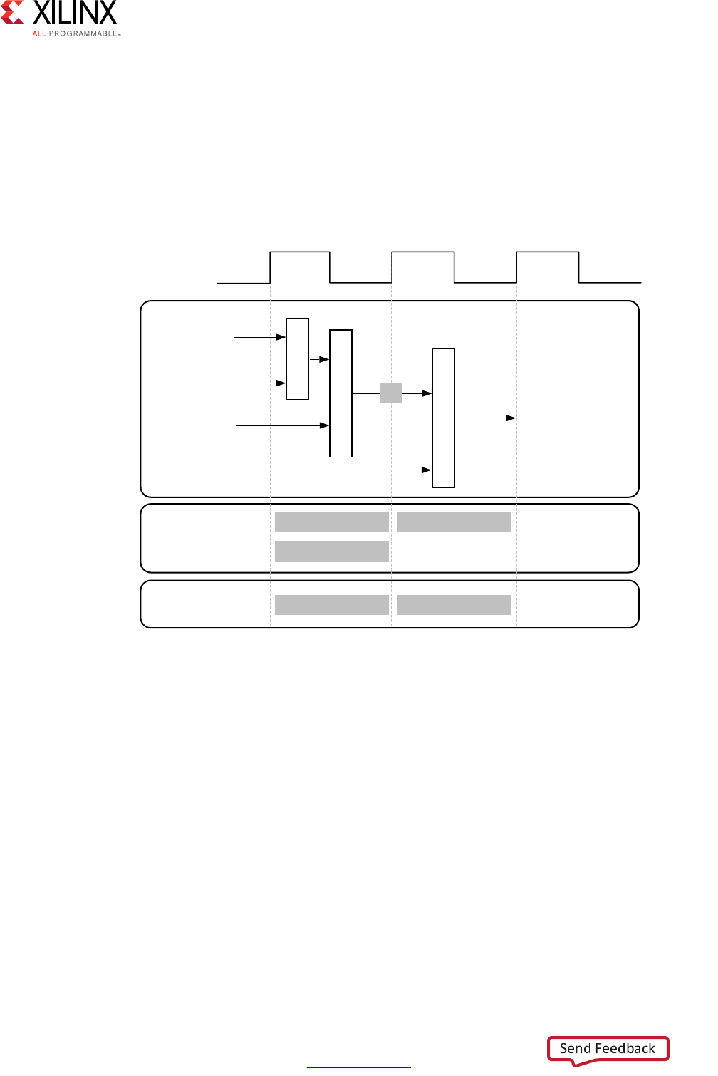
Scheduling and Binding Example
The following figure shows an example of the scheduling and binding phases for this code
example:
int foo(char x, char a, char b, char c) {
char y;
y = x*a+b+c;
return y
}
In the scheduling phase of this example, high-level synthesis schedules the following
operations to occur during each clock cycle:
• First clock cycle: Multiplication and the first addition
• Second clock cycle: Second addition and output generation
Note: In the preceding figure, the square between the first and second clock cycles indicates when
an internal register stores a variable. In this example, high-level synthesis only requires that the
output of the addition is registered across a clock cycle. The first cycle reads x, a, and b data ports.
The second cycle reads data port c and generates output y.
X-Ref Target - Figure 1-1
Figure 1-1: Scheduling and Binding Example
7DUJHW%LQGLQJ
3KDVH '63 $GG6XE
,QLWLDO%LQGLQJ
3KDVH
6FKHGXOLQJ
3KDVH
;
&ORFN&\FOH
D
[
E
F
\
0XO $GG6XE
$GG6XE

High-Level Synthesis 9
UG902 (v2017.1) April 5, 2017 www.xilinx.com
Chapter 1: High-Level Synthesis
In the final hardware implementation, high-level synthesis implements the arguments to
the top-level function as input and output (I/O) ports. In this example, the arguments are
simple data ports. Because each input variables is a char type, the input data ports are all
8-bits wide. The function return is a 32-bit int data type, and the output data port is
32-bits wide.
IMPORTANT: The advantage of implementing the C code in the hardware is that all operations finish
in a shorter number of clock cycles. In this example, the operations complete in only two clock cycles.
In a central processing unit (CPU), even this simple code example takes more clock cycles to complete.
In the initial binding phase of this example, high-level synthesis implements the multiplier
operation using a combinational multiplier (Mul) and implements both add operations
using a combinational adder/subtractor (AddSub).
In the target binding phase, high-level synthesis implements both the multiplier and one of
the addition operations using a DSP48 resource. The DSP48 resource is a computational
block available in the FPGA architecture that provides the ideal balance of
high-performance and efficient implementation.
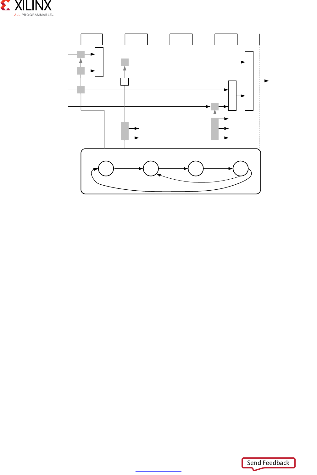
Extracting Control Logic and Implementing I/O Ports Example
The following figure shows the extraction of control logic and implementation of I/O ports
for this code example:
void foo(int in[3], char a, char b, char c, int out[3]) {
int x,y;
for(int i = 0; i < 3; i++) {
x = in[i];
y = a*x + b + c;
out[i] = y;
}
}
High-Level Synthesis 10
UG902 (v2017.1) April 5, 2017 www.xilinx.com
Chapter 1: High-Level Synthesis
This code example performs the same operations as the previous example. However, it
performs the operations inside a for-loop, and two of the function arguments are arrays.
The resulting design executes the logic inside the for-loop three times when the code is
scheduled. High-level synthesis automatically extracts the control logic from the C code
and creates an FSM in the RTL design to sequence these operations. High-level synthesis
implements the top-level function arguments as ports in the final RTL design. The scalar
variable of type char maps into a standard 8-bit data bus port. Array arguments, such as in
and out, contain an entire collection of data.
In high-level synthesis, arrays are synthesized into block RAM by default, but other options
are possible, such as FIFOs, distributed RAM, and individual registers. When using arrays as
arguments in the top-level function, high-level synthesis assumes that the block RAM is
outside the top-level function and automatically creates ports to access a block RAM
outside the design, such as data ports, address ports, and any required chip-enable or
write-enable signals.
The FSM controls when the registers store data and controls the state of any I/O control
signals. The FSM starts in the state C0. On the next clock, it enters state C1, then state C2,
and then state C3. It returns to state C1 (and C2, C3) a total of three times before returning
to state C0.
Note: This closely resembles the control structure in the C code for-loop. The full sequence of states
are: C0,{C1, C2, C3}, {C1, C2, C3}, {C1, C2, C3}, and return to C0.
X-Ref Target - Figure 1-2
Figure 1-2: Control Logic Extraction and I/O Port Implementation Example
&ORFN
E
F
D
LQBGDWD
RXWBFH
RXWBZH
RXWBDGGU
LQBDGGU
LQBFH
[
\
)LQLWH6WDWH0DFKLQH)60
& & & &
[
;
RXWBGDWD

High-Level Synthesis 11
UG902 (v2017.1) April 5, 2017 www.xilinx.com
Chapter 1: High-Level Synthesis
The design requires the addition of b and c only one time. High-level synthesis moves the
operation outside the for-loop and into state C0. Each time the design enters state C3, it
reuses the result of the addition.
The design reads the data from in and stores the data in x. The FSM generates the address
for the first element in state C1. In addition, in state C1, an adder increments to keep track
of how many times the design must iterate around states C1, C2, and C3. In state C2, the
block RAM returns the data for in and stores it as variable x.
High-level synthesis reads the data from port a with other values to perform the calculation
and generates the first y output. The FSM ensures that the correct address and control
signals are generated to store this value outside the block. The design then returns to state
C1 to read the next value from the array/block RAM in. This process continues until all
output is written. The design then returns to state C0 to read the next values of b and c to
start the process again.
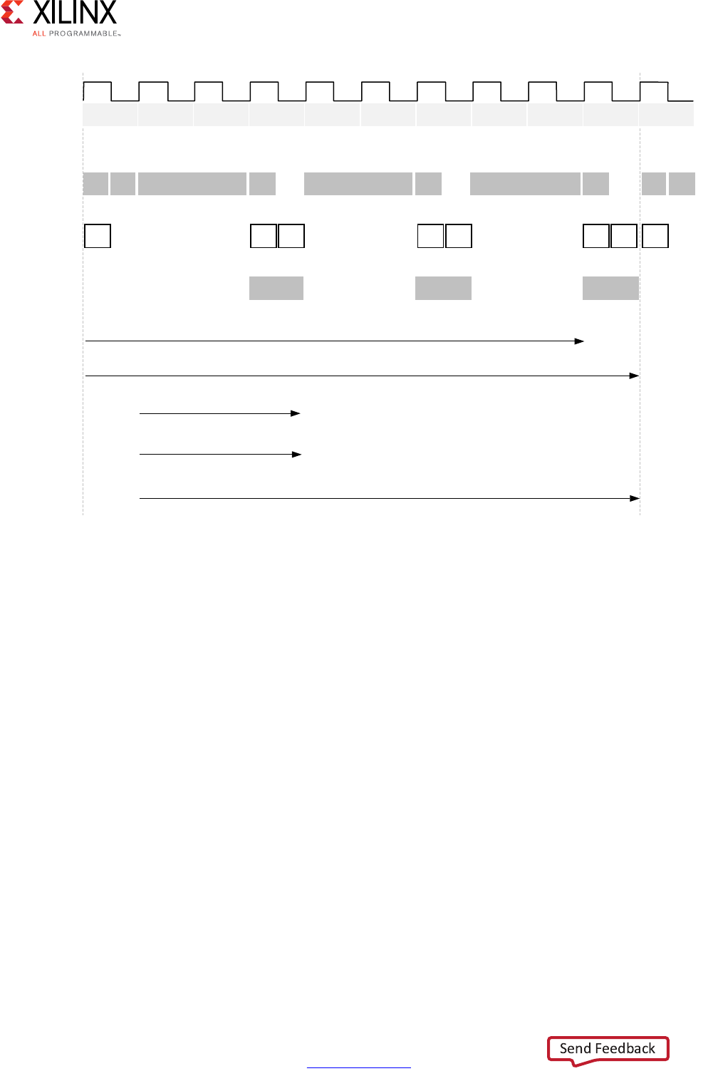
Performance Metrics Example
The following figure shows the complete cycle-by-cycle execution for the code in the
Extracting Control Logic and Implementing I/O Ports Example, including the states for each
clock cycle, read operations, computation operations, and write operations.
High-Level Synthesis 12
UG902 (v2017.1) April 5, 2017 www.xilinx.com
Chapter 1: High-Level Synthesis
Following are the performance metrics for this example:
• Latency: It takes the function 9 clock cycles to output all values.
Note: When the output is an array, the latency is measured to the last array value output.
• II: The II is 10, which means it takes 10 clock cycles before the function can initiate a
new set of input reads and start to process the next set of input data.
Note: The time to perform one complete execution of a function is referred to as one
transaction. In this example, it takes 11 clock cycles before the function can accept data for the
next transaction.
• Loop iteration latency: The latency of each loop iteration is 3 clock cycles.
• Loop II: The interval is 3.
• Loop latency: The latency is 9 clock cycles.
X-Ref Target - Figure 1-3
Figure 1-3: Latency and Initiation Interval Example
E
& & & & & & & & & & &
5HDG%
DQG&
$GGU
LQ>@
5HDG
LQ>@
&DOF
RXW>@
$GGU
LQ>@
5HDG
LQ>@
&DOF
RXW>@
$GGU
LQ>@
5HDG
LQ>@
&DOF
RXW>@
5HDG%
DQG&
F $GGU[ 'DWD D $GGU[ 'DWD D $GGU[ 'DWD D E F
<>@ <>@ <>@
)XQFWLRQ/DWHQF\
)XQFWLRQ,QLWLDWLRQ,QWHUYDO
/RRS,WHUDWLRQ/DWHQF\
/RRS,WHUDWLRQ,QWHUYDO
/RRS/DWHQF\
;

High-Level Synthesis 13
UG902 (v2017.1) April 5, 2017 www.xilinx.com
Chapter 1: High-Level Synthesis
Understanding Vivado HLS
The Xilinx Vivado HLS tool synthesizes a C function into an IP block that you can integrate
into a hardware system. It is tightly integrated with the rest of the Xilinx design tools and
provides comprehensive language support and features for creating the optimal
implementation for your C algorithm.
Following is the Vivado HLS design flow:
1. Compile, execute (simulate), and debug the C algorithm.
Note: In high-level synthesis, running the compiled C program is referred to as C simulation.
Executing the C algorithm simulates the function to validate that the algorithm is functionally
correct.
2. Synthesize the C algorithm into an RTL implementation, optionally using user
optimization directives.
3. Generate comprehensive reports and analyze the design.
4. Verify the RTL implementation using a pushbutton flow.
5. Package the RTL implementation into a selection of IP formats.
Inputs and Outputs
Following are the inputs to Vivado HLS:
• C function written in C, C++, SystemC, or an OpenCL API C kernel
This is the primary input to Vivado HLS. The function can contain a hierarchy of
sub-functions.
•Constraints
Constraints are required and include the clock period, clock uncertainty, and FPGA
target. The clock uncertainty defaults to 12.5% of the clock period if not specified.
•Directives
Directives are optional and direct the synthesis process to implement a specific
behavior or optimization.
• C test bench and any associated files
Vivado HLS uses the C test bench to simulate the C function prior to synthesis and to
verify the RTL output using C/RTL Cosimulation.

High-Level Synthesis 14
UG902 (v2017.1) April 5, 2017 www.xilinx.com
Chapter 1: High-Level Synthesis
You can add the C input files, directives, and constraints to a Vivado HLS project
interactively using the Vivado HLS graphical user interface (GUI) or using Tcl commands at
the command prompt. You can also create a Tcl file and execute the commands in batch
mode.
Following are the outputs from Vivado HLS:
• RTL implementation files in hardware description language (HDL) formats
This is the primary output from Vivado HLS. Using Vivado synthesis, you can synthesize
the RTL into a gate-level implementation and an FPGA bitstream file. The RTL is available
in the following industry standard formats:
°VHDL (IEEE 1076-2000)
°Verilog (IEEE 1364-2001)
Vivado HLS packages the implementation files as an IP block for use with other tools in
the Xilinx design flow. Using logic synthesis, you can synthesize the packaged IP into an
FPGA bitstream.
•Report files
This output is the result of synthesis, C/RTL co-simulation, and IP packaging.
High-Level Synthesis 15
UG902 (v2017.1) April 5, 2017 www.xilinx.com
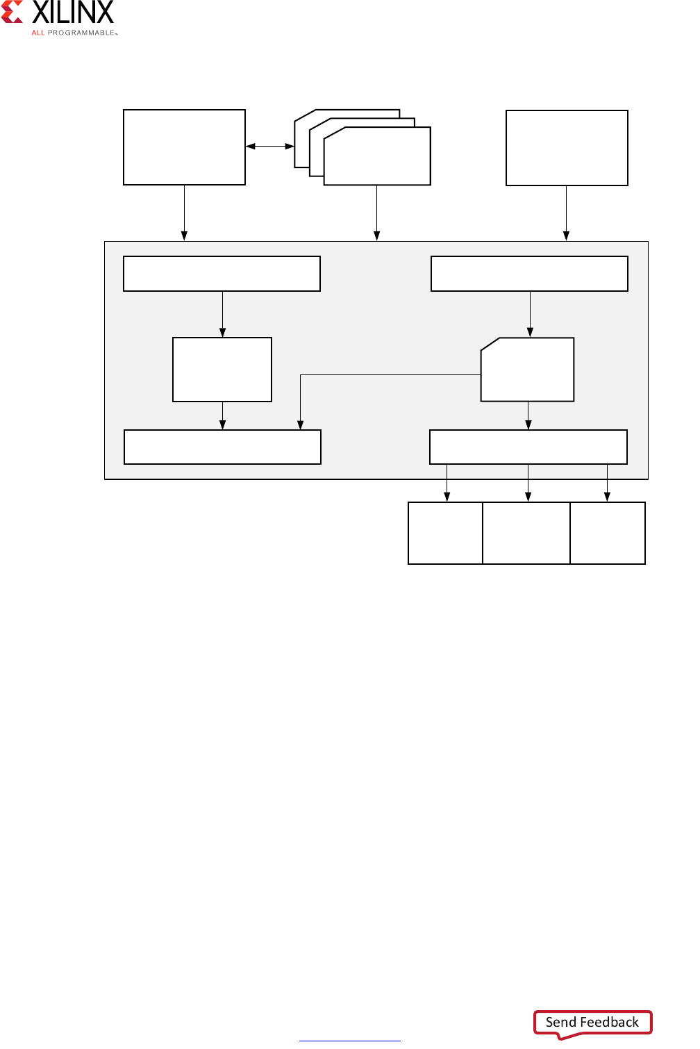
Chapter 1: High-Level Synthesis
The following figure shows an overview of the Vivado HLS input and output files.
Test Bench, Language Support, and C Libraries
In any C program, the top-level function is called main(). In the Vivado HLS design flow,
you can specify any sub-function below main() as the top-level function for synthesis. You
cannot synthesize the top-level function main(). Following are additional rules:
• Only one function is allowed as the top-level function for synthesis.
• Any sub-functions in the hierarchy under the top-level function for synthesis are also
synthesized.
• If you want to synthesize functions that are not in the hierarchy under the top-level
function for synthesis, you must merge the functions into a single top-level function for
synthesis.
• The verification flow for OpenCL API C kernels requires special handling in the Vivado
HLS flow. For more information, see OpenCL API C Test Benches in Chapter 3.
X-Ref Target - Figure 1-4
Figure 1-4: Vivado HLS Design Flow
7HVW
%HQFK
&RQVWUDLQWV
'LUHFWLYHV
9LYDGR+/6
&6LPXODWLRQ &6\QWKHVLV
57/
$GDSWHU
9+'/
9HULORJ
57/6LPXODWLRQ 3DFNDJHG,3
9LYDGR
'HVLJQ
6XLWH
6\VWHP
*HQHUDWRU
;LOLQ[
3ODWIRUP
6WXGLR
;
&&
6\VWHP&
2SHQ&/$3,&
High-Level Synthesis 16
UG902 (v2017.1) April 5, 2017 www.xilinx.com
Chapter 1: High-Level Synthesis
Test Bench
When using the Vivado HLS design flow, it is time consuming to synthesize a functionally
incorrect C function and then analyze the implementation details to determine why the
function does not perform as expected. To improve productivity, use a test bench to
validate that the C function is functionally correct prior to synthesis.
The C test bench includes the function main() and any sub-functions that are not in the
hierarchy under the top-level function for synthesis. These functions verify that the
top-level function for synthesis is functionally correct by providing stimuli to the function
for synthesis and by consuming its output.
Vivado HLS uses the test bench to compile and execute the C simulation. During the
compilation process, you can select the Launch Debugger option to open a full C-debug
environment, which enables you to analyze the C simulation. For more information on test
benches, see C Test Bench in Chapter 3.
RECOMMENDED: Because Vivado HLS uses the test bench to both verify the C function prior to
synthesis and to automatically verify the RTL output, using a test bench is highly recommended.
Language Support
Vivado HLS supports the following standards for C compilation/simulation:
• ANSI-C (GCC 4.6)
• C++ (G++ 4.6)
• OpenCL API (1.0 embedded profile)
• SystemC (IEEE 1666-2006, version 2.2)
C, C++, and SystemC Language Constructs
Vivado HLS supports many C, C++, and SystemC language constructs and all native data
types for each language, including float and double types. However, synthesis is not
supported for some constructs, including:
• Dynamic memory allocation
An FPGA has a fixed set of resources, and the dynamic creation and freeing of memory
resources is not supported.
• Operating system (OS) operations
All data to and from the FPGA must be read from the input ports or written to output
ports. OS operations, such as file read/write or OS queries like time and date, are not
supported. Instead, the C test bench can perform these operations and pass the data
into the function for synthesis as function arguments.

High-Level Synthesis 17
UG902 (v2017.1) April 5, 2017 www.xilinx.com
Chapter 1: High-Level Synthesis
For details on the supported and unsupported C constructs and examples of each of the
main constructs, see Chapter 3, High-Level Synthesis Coding Styles.
OpenCL API C Language Constructs
Vivado HLS supports the OpenCL API C language constructs and built-in functions from the
OpenCL API C 1.0 embedded profile.
C Libraries
C libraries contain functions and constructs that are optimized for implementation in an
FPGA. Using these libraries helps to ensure high quality of results (QoR), that is, the final
output is a high-performance design that makes optimal use of the resources. Because the
libraries are provided in C, C++, OpenCL API C, or SystemC, you can incorporate the
libraries into the C function and simulate them to verify the functional correctness before
synthesis.
Vivado HLS provides the following C libraries to extend the standard C languages:
• Arbitrary precision data types
• Half-precision (16-bit) floating-point data types
•Math operations
• Video functions
• Xilinx IP functions, including fast fourier transform (FFT) and finite impulse response
(FIR)
• FPGA resource functions to help maximize the use of shift register LUT (SRL) resources
For more information on the C libraries provided by Vivado HLS, see Chapter 2, High-Level
Synthesis C Libraries.
C Library Example
C libraries ensure a higher QoR than standard C types. Standard C types are based on 8-bit
boundaries (8-bit, 16-bit, 32-bit, 64-bit). However, when targeting a hardware platform, it is
often more efficient to use data types of a specific width.
For example, a design with a filter function for a communications protocol requires 10-bit
input data and 18-bit output data to satisfy the data transmission requirements. Using
standard C data types, the input data must be at least 16-bits and the output data must be
at least 32-bits. In the final hardware, this creates a datapath between the input and output
that is wider than necessary, uses more resources, has longer delays (for example, a 32-bit
by 32-bit multiplication takes longer than an 18-bit by 18-bit multiplication), and requires
more clock cycles to complete.

High-Level Synthesis 18
UG902 (v2017.1) April 5, 2017 www.xilinx.com
Chapter 1: High-Level Synthesis
Using an arbitrary precision data type in this design instead, you can specify the exact
bit-sizes to be specified in the C code prior to synthesis, simulate the updated C code, and
verify the quality of the output using C simulation prior to synthesis. Arbitrary precision
data types are provided for C and C++ and allow you to model data types of any width from
1 to 1024-bit. For example, you can model some C++ types up to 32768 bits. For more
information on arbitrary precision data types, see Data Types for Efficient Hardware.
Note: Arbitrary precision types are only required on the function boundaries, because Vivado HLS
optimizes the internal logic and removes data bits and logic that do not fanout to the output ports.
Synthesis, Optimization, and Analysis
Vivado HLS is project based. Each project holds one set of C code and can contain multiple
solutions. Each solution can have different constraints and optimization directives. You can
analyze and compare the results from each solution in the Vivado HLS GUI.
Following are the synthesis, optimization, and analysis steps in the Vivado HLS design
process:
1. Create a project with an initial solution.
2. Verify the C simulation executes without error.
3. Run synthesis to obtain a set of results.
4. Analyze the results.
After analyzing the results, you can create a new solution for the project with different
constraints and optimization directives and synthesize the new solution. You can repeat this
process until the design has the desired performance characteristics. Using multiple
solutions allows you to proceed with development while still retaining the previous results.
Optimization
Using Vivado HLS, you can apply different optimization directives to the design, including:
• Instruct a task to execute in a pipeline, allowing the next execution of the task to begin
before the current execution is complete.
• Specify a latency for the completion of functions, loops, and regions.
• Specify a limit on the number of resources used.
• Override the inherent or implied dependencies in the code and permit specified
operations. For example, if it is acceptable to discard or ignore the initial data values,
such as in a video stream, allow a memory read before write if it results in better
performance.
• Select the I/O protocol to ensure the final design can be connected to other hardware
blocks with the same I/O protocol.
High-Level Synthesis 19
UG902 (v2017.1) April 5, 2017 www.xilinx.com
Chapter 1: High-Level Synthesis
Note: Vivado HLS automatically determines the I/O protocol used by any sub-functions. You
cannot control these ports except to specify whether the port is registered. For more information
on working with I/O interfaces, see Managing Interfaces.
You can use the Vivado HLS GUI to place optimization directives directly into the source
code. Alternatively, you can use Tcl commands to apply optimization directives. For more
information on the various optimizations, see Optimizing the Design.
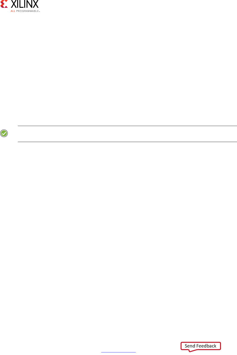
Analysis
When synthesis completes, Vivado HLS automatically creates synthesis reports to help you
understand the performance of the implementation. In the Vivado HLS GUI, the Analysis
Perspective includes the Performance tab, which allows you to interactively analyze the
results in detail. The following figure shows the Performance tab for the Extracting Control
Logic and Implementing I/O Ports Example.
The Performance tab shows the following for each state:
•C0: The first state includes read operations on ports a, b, and c and the addition
operation.
•C1 and C2: The design enters a loop and checks the loop increment counter and exit
condition. The design then reads data into variable x, which requires two clock cycles.
Two clock cycles are required, because the design is accessing a block RAM, requiring
an address in one cycle and a data read in the next.
•C3: The design performs the calculations and writes output to port y. Then, the loop
returns to the start.
X-Ref Target - Figure 1-5
Figure 1-5: Vivado HLS Analysis Example

High-Level Synthesis 20
UG902 (v2017.1) April 5, 2017 www.xilinx.com
Chapter 1: High-Level Synthesis
OpenCL API C Kernel Synthesis
IMPORTANT: For OpenCL API C kernels, Vivado HLS always synthesizes logic for the entire work group.
You cannot apply the standard Vivado HLS interface directives to an OpenCL API C kernel.
The following OpenCL API C kernel code shows a vector addition design where two arrays
of data are summed into a third. The required size of the work group is 16, that is, this kernel
must execute a minimum of 16 times to produce a valid result.
#include <clc.h>
// For VHLS OpenCL C kernels, the full work group is synthesized
__kernel void __attribute__ ((reqd_work_group_size(16, 1, 1)))
vadd(__global int* a,
__global int* b,
__global int* c)
{
int idx = get_global_id(0);
c[idx] = a[idx] + b[idx];
}
Vivado HLS synthesizes this design into hardware that performs the following:
• 16 reads from interface a and b
• 16 additions and 16 writes to output interface c
RTL Verification
If you added a C test bench to the project, you can use it to verify that the RTL is functionally
identical to the original C. The C test bench verifies the output from the top-level function
for synthesis and returns zero to the top-level function main() if the RTL is functionally
identical. Vivado HLS uses this return value for both C simulation and C/RTL co-simulation
to determine if the results are correct. If the C test bench returns a non-zero value, Vivado
HLS reports that the simulation failed.
IMPORTANT: Even if the output data is correct and valid, Vivado HLS reports a simulation failure if the
test bench does not return the value zero to function main().
TIP: For test bench examples that you can use for reference, see Design Examples and References.

High-Level Synthesis 21
UG902 (v2017.1) April 5, 2017 www.xilinx.com
Chapter 1: High-Level Synthesis
Vivado HLS automatically creates the infrastructure to perform the C/RTL co-simulation and
automatically executes the simulation using one of the following supported RTL simulators:
• Vivado Simulator (XSim)
• ModelSim simulator
•VCS
•NCSim
• Riviera
If you select Verilog or VHDL HDL for simulation, Vivado HLS uses the HDL simulator you
specify. The Xilinx design tools include Vivado Simulator. Third-party HDL simulators
require a license from the third-party vendor. The VCS and NCSim simulators are only
supported on the Linux operating system. For more information, see Using C/RTL
Co-Simulation.
RTL Export
Using Vivado HLS, you can export the RTL and package the final RTL output files as IP in any
of the following Xilinx IP formats:
• Vivado IP Catalog
Import into the Vivado IP catalog for use in the Vivado Design Suite.
• System Generator for DSP
Import the HLS design into System Generator.
• Synthesized Checkpoint (.dcp)
Import directly into the Vivado Design Suite the same way you import any Vivado
Design Suite checkpoint.
Note: The synthesized checkpoint format invokes logic synthesis and compiles the RTL
implementation into a gate-level implementation, which is included in the IP package.

High-Level Synthesis 22
UG902 (v2017.1) April 5, 2017 www.xilinx.com
Chapter 1: High-Level Synthesis
For all IP formats except the synthesized checkpoint, you can optionally execute logic
synthesis from within Vivado HLS to evaluate the results of RTL synthesis or
implementation. This optional step allows you to confirm the estimates provided by Vivado
HLS for timing and area before handing off the IP package. These gate-level results are not
included in the packaged IP.
Note: Vivado HLS estimates the timing and area resources based on built-in libraries for each FPGA.
When you use logic synthesis to compile the RTL into a gate-level implementation, perform physical
placement of the gates in the FPGA, and perform routing of the inter-connections between gates,
logic synthesis might make additional optimizations that change the Vivado HLS estimates.
For more information, see Exporting the RTL Design.
Using Vivado HLS
To invoke Vivado HLS on a Windows platform double-click the desktop button as shown in
the following figure.
To invoke Vivado HLS on a Linux platform (or from the Vivado HLS Command Prompt on
Windows) execute the following command at the command prompt.
$ vivado_hls
The Vivado HLS GUI opens as shown in the following figure.
X-Ref Target - Figure 1-6
Figure 1-6: Vivado HLS GUI Button
High-Level Synthesis 23
UG902 (v2017.1) April 5, 2017 www.xilinx.com
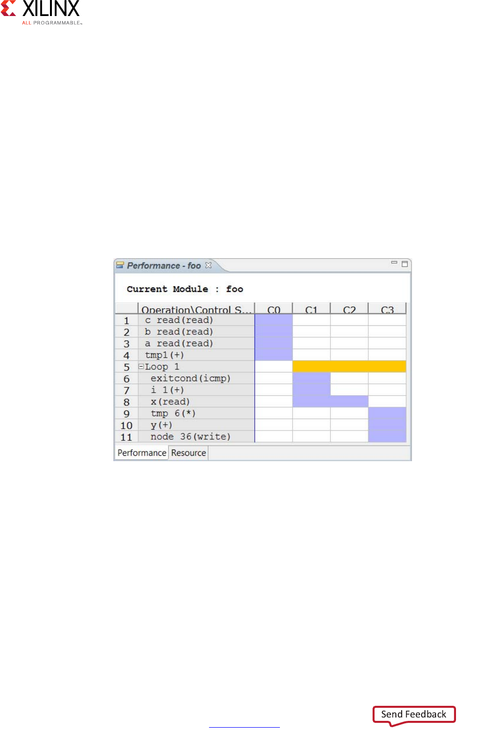
Chapter 1: High-Level Synthesis
You can use the Quick Start options to perform the following tasks:
•Create New Project: Launch the project setup wizard.
•Open Project: Navigate to an existing project or select from a list of recent projects.
•Open Example Project: Open Vivado HLS examples. For details on these examples, see
Design Examples and References.
You can use the Documentation options to perform the following tasks:
•Tutorials: Opens the Vivado Design Suite Tutorial: High-Level Synthesis (UG871) [Ref 2].
For details on the tutorial examples, see Design Examples and References.
•User Guide: Opens this document, the Vivado Design Suite User Guide: High-Level
Synthesis (UG902).
•Release Notes Guide: Opens the Vivado Design Suite User Guide: Release Notes,
Installation, and Licensing (UG973) [Ref 3] for the latest software version.
X-Ref Target - Figure 1-7
Figure 1-7: Vivado HLS GUI Welcome Page
High-Level Synthesis 24
UG902 (v2017.1) April 5, 2017 www.xilinx.com
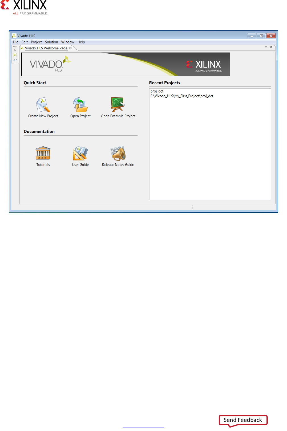
Chapter 1: High-Level Synthesis
The primary controls for using Vivado HLS are shown in the toolbar in the following figure.
Project control ensures only commands that can be currently executed are highlighted. For
example, synthesis must be performed before C/RTL co-simulation can be executed. The
C/RTL co-simulation toolbar buttons remain gray until synthesis completes.
In the Project Management section, the buttons are (from left to right):
•Create New Project opens the new project wizard.
•Project Settings allows the current project settings to be modified.
•New Solution opens the new solution dialog box.
•Solution Settings allows the current solution settings to be modified.
The next group of toolbar buttons control the tool operation (from left to right):
•Index C Source refreshes the annotations in the C source.
•Run C Simulation opens the C Simulation dialog box.
•C Synthesis starts C source code in Vivado HLS.
•Run C/RTL Cosimulation verifies the RTL output.
•Export RTL packages the RTL into the desired IP output format.
The final group of toolbar buttons are for design analysis (from left to right):
•Open Report opens the C synthesis report or drops down to open other reports.
•Compare Reports allows the reports from different solutions to be compared.
X-Ref Target - Figure 1-8
Figure 1-8: Vivado HLS Controls
High-Level Synthesis 25
UG902 (v2017.1) April 5, 2017 www.xilinx.com
Chapter 1: High-Level Synthesis
Each of the buttons on the toolbar has an equivalent command in the menus. In addition,
Vivado HLS GUI provides three perspectives. When you select a perspective, the windows
automatically adjust to a more suitable layout for the selected task.
•The Debug perspective opens the C debugger.
•The Synthesis perspective is the default perspective and arranges the windows for
performing synthesis.
•The Analysis perspective is used after synthesis completes to analyze the design in
detail. This perspective provides considerable more detail than the synthesis report.
Changing between perspectives can be done at any time by selecting the desired
perspective button.
The remainder of this chapter discusses how to use Vivado HLS. The following topics are
discussed:
• How to create a Vivado HLS synthesis project.
• How to simulate and debug the C code.
• How to synthesize the design, create new solutions and add optimizations.
• How to perform design analysis.
• How to verify and package the RTL output.
• How to use the Vivado HLS Tcl commands and batch mode.
This chapter ends with a review of the design examples, tutorials, and resources for more
information.
Creating a New Synthesis Project
To create a new project, click the Create New Project link on the Welcome page shown in
Figure 1-7, or select the File > New Project menu command. This opens the project wizard
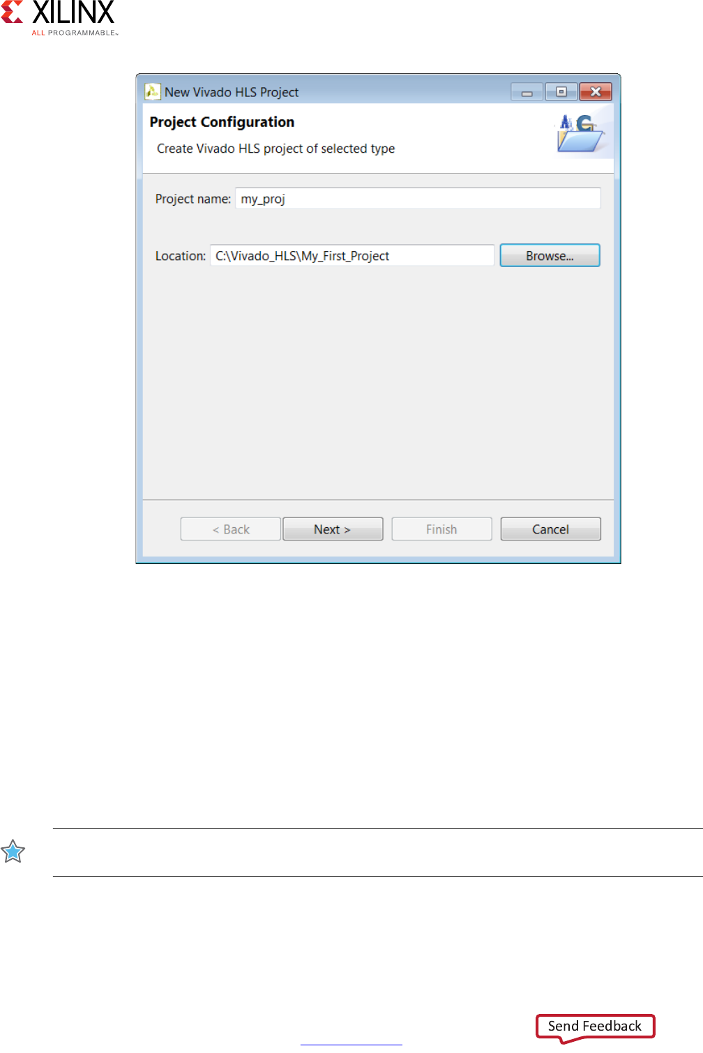
shown in Figure 1-9, which allows you to specify the following:
•Project Name: Specifies the project name, which is also the name of the directory in
which the project details are stored.
•Location: Specifies where to store the project.
CAUTION! The Windows operating system has a 260-character limit for path lengths, which can affect
the Vivado tools. To avoid this issue, use the shortest possible names and directory locations when
creating projects, defining IP or managed IP projects, and creating block designs.
High-Level Synthesis 26
UG902 (v2017.1) April 5, 2017 www.xilinx.com
Chapter 1: High-Level Synthesis
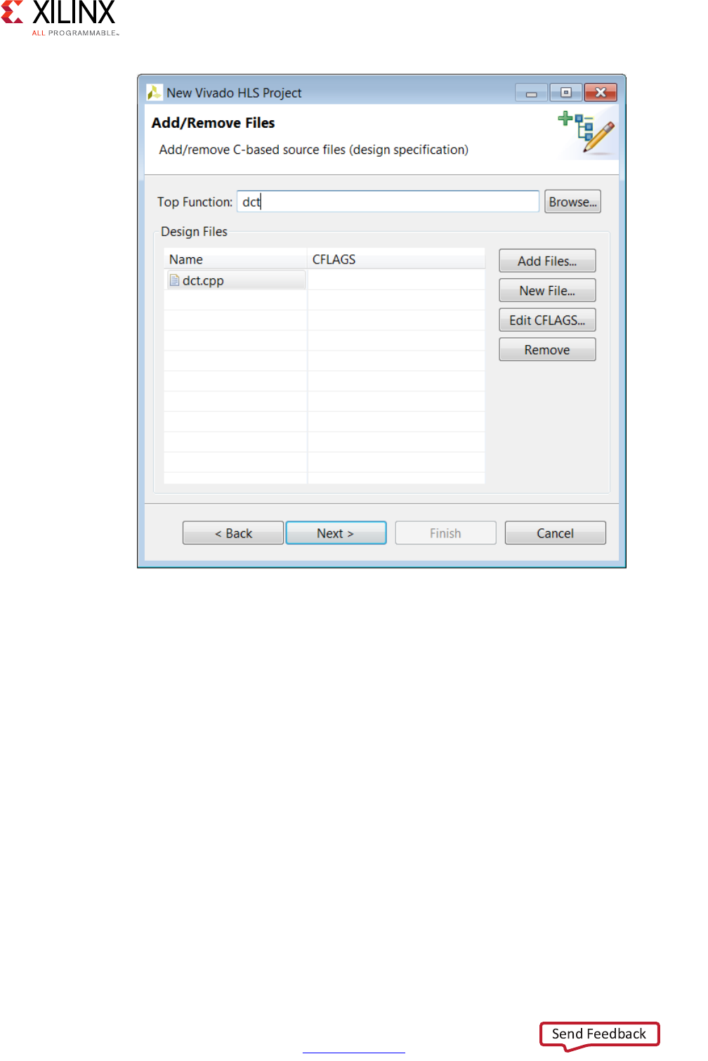
Selecting the Next > button moves the wizard to the second screen where you can enter
details in the project C source files (Figure 1-10).
•Top Function: Specifies the name of the top-level function to be synthesized. If you
add the C files first, you can use the Browse button to review the C hierarchy, and then
select the top-level function for synthesis. The Browse button remains grayed out until
you add the source files.
Note: This step is not required when the project is specified as SystemC, because Vivado HLS
automatically identifies the top-level functions.
Use the Add Files button to add the source code files to the project.
IMPORTANT: Do not add header files (with the .h suffix) to the project using the Add Files button (or
with the associated add_files Tcl command).
X-Ref Target - Figure 1-9
Figure 1-9: Project Specification
High-Level Synthesis 27
UG902 (v2017.1) April 5, 2017 www.xilinx.com
Chapter 1: High-Level Synthesis
Vivado HLS automatically adds the following directories to the search path:
• Working directory
Note: The working directory contains the Vivado HLS project directory.
• Any directory that contains C files added to the project
Header files that reside in these directories are automatically included in the project. You
must specify the path to all other header files using the Edit CFLAGS button.
The Edit CFLAGS button specifies the C compiler flags options required to compile the C
code. These compiler flag options are the same used in gcc or g++. C compiler flags include
the path name to header files, macro specifications, and compiler directives, as shown in
the following examples:
•-I/project/source/headers: Provides the search path to associated header files
Note: You must specify relative path names in relation to the working directory not the project
directory.
•-DMACRO_1: Defines macro MACRO_1 during compilation
•-fnested-functions: Defines directives required for any design that contains nested
functions
TIP: For a complete list of supported Edit CFLAGS options, see the Option Summary page
(gcc.gnu.org/onlinedocs/gcc/Option-Summary.html) on the GNU Compiler Collection (GCC) website.
TIP: You can use $::env(MY_ENV_VAR) to specify environment variables in CFLAGS.
For example, to include the directory $MY_ENV_VAR/include for compilation, you can specify
-I$::env(MY_ENV_VAR)/include in CFLAGS.
High-Level Synthesis 28
UG902 (v2017.1) April 5, 2017 www.xilinx.com
Chapter 1: High-Level Synthesis
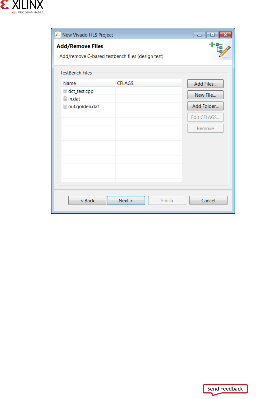
The next window in the project wizard allows you to add the files associated with the test
bench to the project.
Note: For SystemC designs with header files associated with the test bench but not the design file,
you must use the Add Files button to add the header files to the project.
In most of the example designs provided with Vivado HLS, the test bench is in a separate
file from the design. Having the test bench and the function to be synthesized in separate
files keeps a clean separation between the process of simulation and synthesis. If the test
bench is in the same file as the function to be synthesized, the file should be added as a
source file and, as shown in the next step, a test bench file.
X-Ref Target - Figure 1-10
Figure 1-10: Project Source Files
High-Level Synthesis 29
UG902 (v2017.1) April 5, 2017 www.xilinx.com
Chapter 1: High-Level Synthesis
As with the C source files, click the Add Files button to add the C test bench and the Edit
CFLAGS button to include any C compiler options.
In addition to the C source files, all files read by the test bench must be added to the
project. In the example shown in Figure 1-11, the test bench opens file in.dat to supply
input stimuli to the design and file out.golden.dat to read the expected results.
Because the test bench accesses these files, both files must be included in the project.
If the test bench files exist in a directory, the entire directory might be added to the project,
rather than the individual files, using the Add Folders button.
If there is no C test bench, there is no requirement to enter any information here and the
Next > button opens the final window of the project wizard, which allows you to specify the
details for the first solution, as shown in the following figure.
X-Ref Target - Figure 1-11
Figure 1-11: Project Test Bench Files
High-Level Synthesis 30
UG902 (v2017.1) April 5, 2017 www.xilinx.com
Chapter 1: High-Level Synthesis
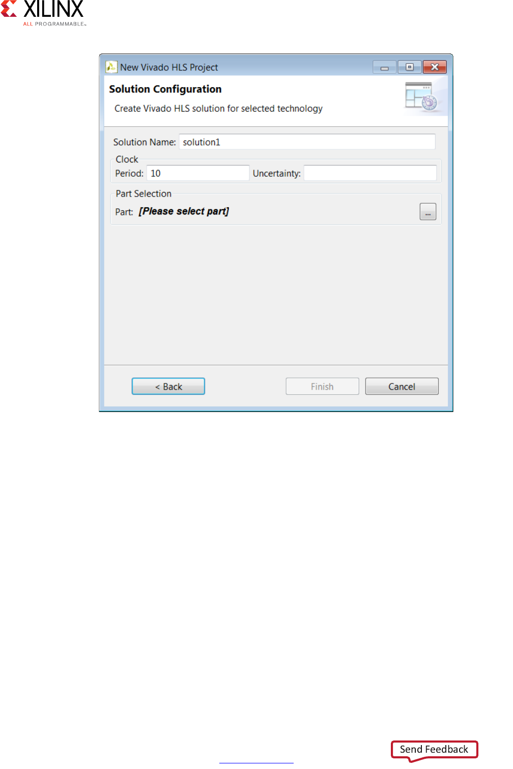
The final window in the new project wizard allows you to specify the details of the first
solution:
•Solution Name: Vivado HLS provides the initial default name solution1, but you can
specify any name for the solution.
•Clock Period: The clock period specified in units of ns or a frequency value specified
with the MHz suffix (For example, 150MHz).
•Uncertainty: The clock period used for synthesis is the clock period minus the clock
uncertainty. Vivado HLS uses internal models to estimate the delay of the operations
for each FPGA. The clock uncertainty value provides a controllable margin to account
for any increases in net delays due to RTL logic synthesis, place, and route. If not
specified in nanoseconds (ns) or a percentage, the clock uncertainty defaults to 12.5%
of the clock period.
•Part: Click to select the appropriate technology, as shown in the following figure.
X-Ref Target - Figure 1-12
Figure 1-12: Initial Solution Settings
High-Level Synthesis 31
UG902 (v2017.1) April 5, 2017 www.xilinx.com
Chapter 1: High-Level Synthesis
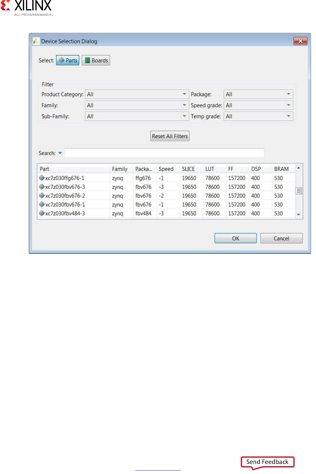
Select the FPGA to be targeted. You can use the filter to reduce the number of device in the
device list. If the target is a board, specify boards in the top-left corner and the device list
is replaced by a list of the supported boards (and Vivado HLS automatically selects the
correct target device).
Clicking Finish opens the project as shown in the following figure.
X-Ref Target - Figure 1-13
Figure 1-13: Part Selection
High-Level Synthesis 32
UG902 (v2017.1) April 5, 2017 www.xilinx.com
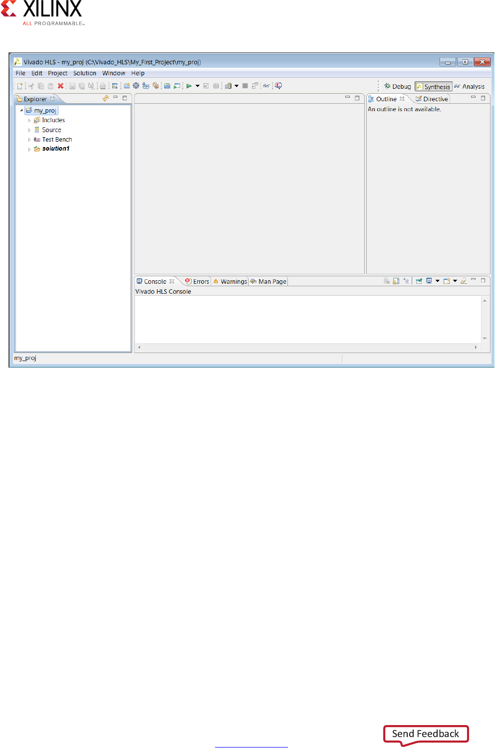
Chapter 1: High-Level Synthesis
The Vivado HLS GUI consists of four panes:
• On the left hand side, the Explorer pane lets you navigate through the project
hierarchy. A similar hierarchy exists in the project directory on the disk.
• In the center, the Information pane displays files. Files can be opened by
double-clicking on them in the Explorer Pane.
• On the right, the Auxiliary pane shows information relevant to whatever file is open in
the Information pane,
• At the bottom, the Console Pane displays the output when Vivado HLS is running.
Simulating the C Code
Verification in the Vivado HLS flow can be separated into two distinct processes.
• Pre-synthesis validation that validates the C program correctly implements the required
functionality.
• Post-synthesis verification that verifies the RTL is correct.
X-Ref Target - Figure 1-14
Figure 1-14: New Project in the Vivado HLS GUI
High-Level Synthesis 33
UG902 (v2017.1) April 5, 2017 www.xilinx.com
Chapter 1: High-Level Synthesis
Both processes are referred to as simulation: C simulation and C/RTL co-simulation.
Before synthesis, the function to be synthesized should be validated with a test bench using
C simulation. A C test bench includes a top-level function main() and the function to be
synthesized. It might include other functions. An ideal test bench has the following
attributes:
• The test bench is self-checking and verifies the results from the function to be
synthesized are correct.
• If the results are correct the test bench returns a value of 0 to main(). Otherwise, the
test bench should return any non-zero values
Vivado HLS synthesizes an OpenCL API C kernel. To simulate an OpenCL API C kernel, you
must use a standard C test bench. You cannot use the OpenCL API C host code as the C test
bench. For more information on test benches, see C Test Bench in Chapter 3.
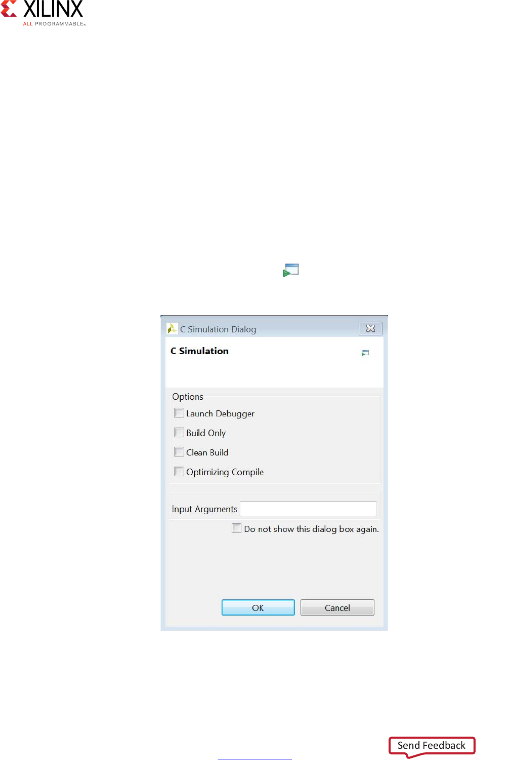
Clicking the Run C Simulation toolbar button opens the C Simulation Dialog box,
shown in the following figure.
If no option is selected in the dialog box, the C code is compiled and the C simulation is
automatically executed. The results are shown in the following figure. When the C code
X-Ref Target - Figure 1-15
Figure 1-15: C Simulation Dialog Box
High-Level Synthesis 34
UG902 (v2017.1) April 5, 2017 www.xilinx.com
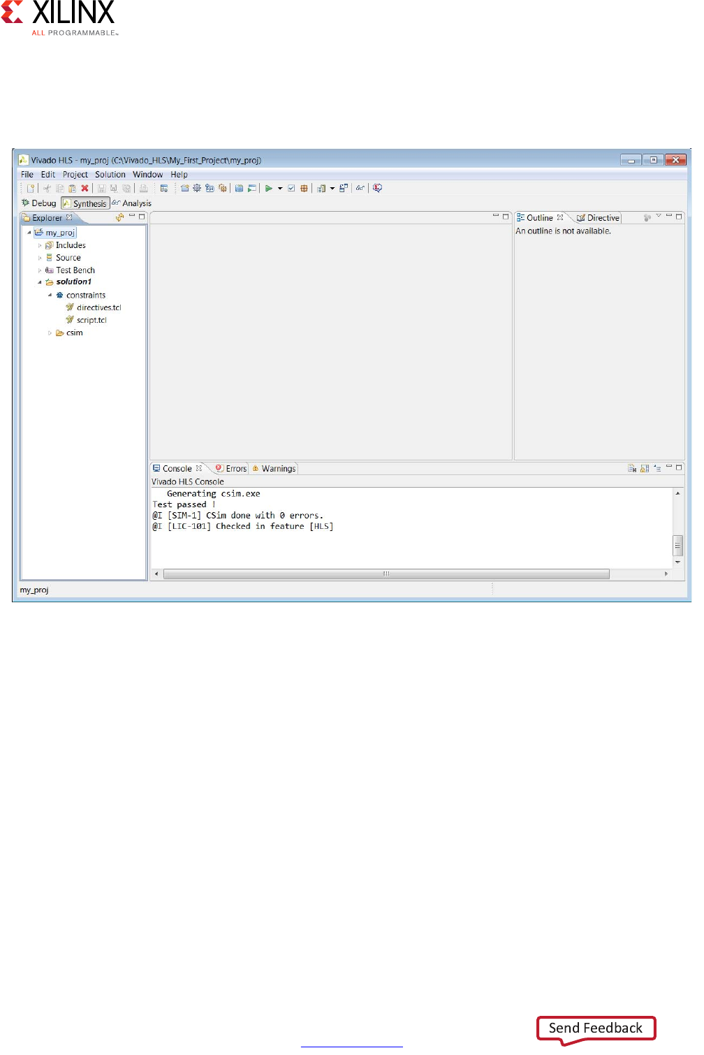
Chapter 1: High-Level Synthesis
simulates successfully, the console window displays a message, as shown in the following
figure. The test bench echoes to the console any printf commands used with the
message “Test Passed!”
The other options in the C Simulation dialog box are:
•Launch Debugger: This compiles the C code and automatically opens the debug
perspective. From within the debug perspective the Synthesis perspective button (top
left) can be used to return the windows to synthesis perspective.
•Build Only: The C code compiles, but the simulation does not run. Details on executing
the C simulation are covered in Reviewing the Output of C Simulation.
•Clean Build: Remove any existing executable and object files from the project before
compiling the code.
•Optimized Compile: By default the design is compiled with debug information,
allowing the compilation to be analyzed in the debug perspective. This option uses a
higher level of optimization effort when compiling the design but removes all
information required by the debugger. This increases the compile time but should
reduce the simulation run time.
X-Ref Target - Figure 1-16
Figure 1-16: C Compiled with Build
High-Level Synthesis 35
UG902 (v2017.1) April 5, 2017 www.xilinx.com
Chapter 1: High-Level Synthesis
•Compiler: Allows you to select between using gcc/g++ or clang to compile the code.
Using clang to compile the code automatically invoke additional code checking
(including the gcc/g++ equivalent -wall option) and optionally allows out-of-range
memory-access and undefined behavior checking through the -clang_sanitizer
option. Use of the sanitizer option increases the memory required to compile the code.
Note: The Compiler option is Linux only and not shown above in Figure 1-15, which displays
the Windows dialog box.
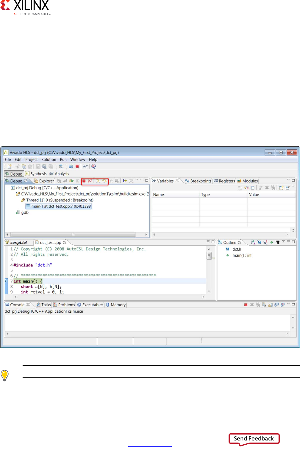
If you select the Launch Debugger option, the windows automatically switch to the debug
perspective and the debug environment opens as shown in the following figure. This is a
full featured C debug environment. The step buttons (red box in the following figure) allow
you to step through code, breakpoints can be set and the value of the variables can be
directly viewed.
TIP: Click the Synthesis perspective button to return to the standard synthesis windows.
X-Ref Target - Figure 1-17
Figure 1-17: C Debug Environment
High-Level Synthesis 36
UG902 (v2017.1) April 5, 2017 www.xilinx.com
Chapter 1: High-Level Synthesis
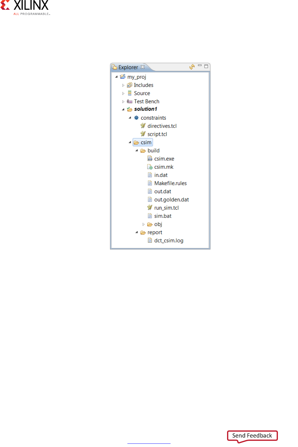
Reviewing the Output of C Simulation
When C simulation completes, a folder csim is created inside the solution folder as shown.
.
The folder csim/build is the primary location for all files related to the C simulation.
• Any files read by the test bench are copied to this folder.
• The C executable file csim.exe is created and run in this folder.
• Any files written by the test bench are created in this folder.
If the Build Only option is selected in the C simulation dialog box, the file csim.exe is
created in this folder but the file is not executed. The C simulation is run manually by
executing this file from a command shell. On Windows the Vivado HLS command shell is
available through the start menu.
The folder csim/report contains a log file of the C simulation.
The next step in the Vivado HLS design flow is to execute synthesis.
X-Ref Target - Figure 1-18
Figure 1-18: C Simulation Output Files
High-Level Synthesis 37
UG902 (v2017.1) April 5, 2017 www.xilinx.com
Chapter 1: High-Level Synthesis
Synthesizing the C Code
The following topics are discussed in this section:
• Creating an Initial Solution.
• Reviewing the Output of C Synthesis.
• Analyzing the Results of Synthesis.
• Creating a New Solution.
• Applying Optimization Directives.
Creating an Initial Solution
Use the C Synthesis toolbar button or the menu Solution > Run C Synthesis to
synthesize the design to an RTL implementation. During the synthesis process messages are
echoed to the console window.
The message include information messages showing how the synthesis process is
proceeding:
INFO: [HLS 200-10] Opening and resetting project
'C:/Vivado_HLS/My_First_Project/proj_dct'.
INFO: [HLS 200-10] Adding design file 'dct.cpp' to the project
INFO: [HLS 200-10] Adding test bench file 'dct_test.cpp' to the project
INFO: [HLS 200-10] Adding test bench file 'in.dat' to the project
INFO: [HLS 200-10] Adding test bench file 'out.golden.dat' to the project
INFO: [HLS 200-10] Opening and resetting solution
'C:/Vivado_HLS/My_First_Project/proj_dct/solution1'.
INFO: [HLS 200-10] Cleaning up the solution database.
INFO: [HLS 200-10] Setting target device to 'xc7k160tfbg484-1'
INFO: [SYN 201-201] Setting up clock 'default' with a period of 4ns.
Within the GUI, some messages may contain links to enhanced information. In the following
example, message XFORM 203-602 is underlined indicating the presence of a hyperlink.
Clicking on this message provides more details on why the message was issued and
possible resolutions. In this case, Vivado HLS automatically inlines small functions and using
the INLINE directive with the -off option may be used to prevent this automatic inlining.
INFO: [XFORM 203-602] Inlining function 'read_data' into 'dct' (dct.cpp:85) automatically.
INFO: [XFORM 203-602] Inlining function 'write_data' into 'dct' (dct.cpp:90) automatically.
High-Level Synthesis 38
UG902 (v2017.1) April 5, 2017 www.xilinx.com
Chapter 1: High-Level Synthesis
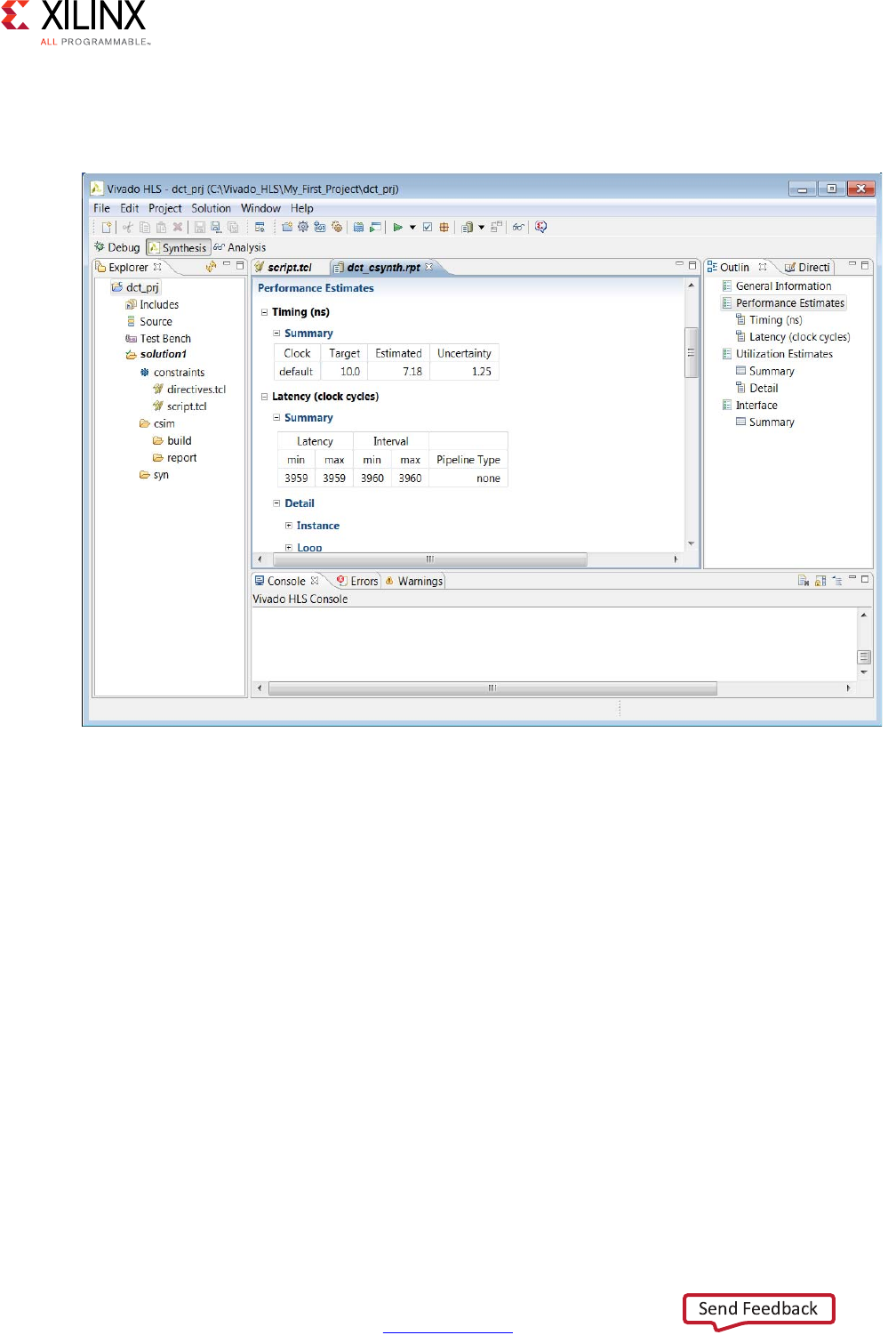
When synthesis completes, the synthesis report for the top-level function opens
automatically in the information pane as shown in the following figure.
Reviewing the Output of C Synthesis
When synthesis completes, the folder syn is now available in the solution folder.
X-Ref Target - Figure 1-19
Figure 1-19: Synthesis Report
High-Level Synthesis 39
UG902 (v2017.1) April 5, 2017 www.xilinx.com
Chapter 1: High-Level Synthesis
The syn folder contains 4 sub-folders. A report folder and one folder for each of the RTL
output formats.
The report folder contains a report file for the top-level function and one for every
sub-function in the design: provided the function was not inlined using the INLINE directive
or inlined automatically by Vivado HLS. The report for the top-level function provides
details on the entire design.
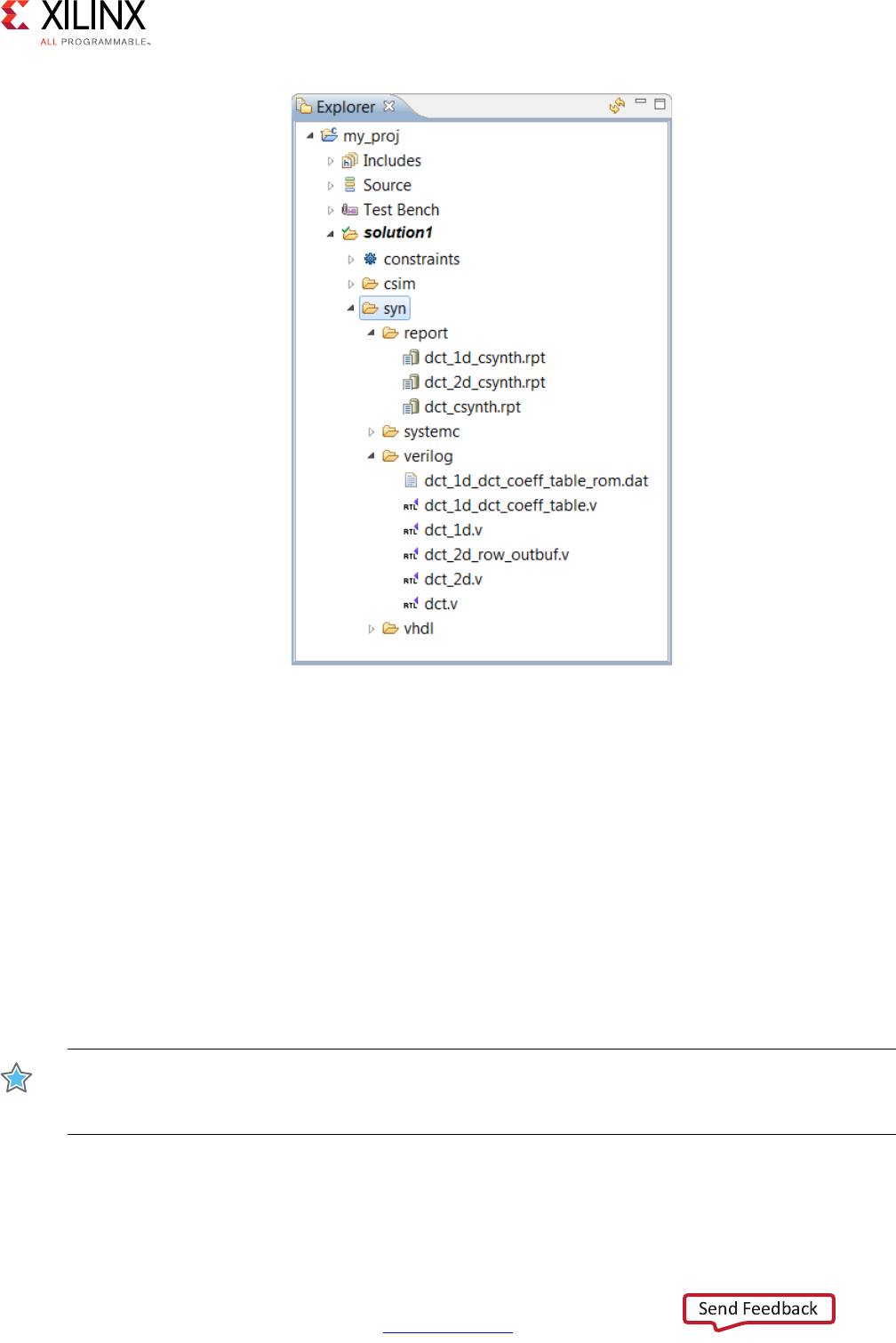
The verilog, vhdl, and systemc folders contain the output RTL files. Figure 1-20 shows
the verilog folder expanded. The top-level file has the same name as the top-level
function for synthesis. In the C design there is one RTL file for each function (not inlined).
There might be additional RTL files to implement sub-blocks (block RAM, pipelined
multipliers, etc).
IMPORTANT: Xilinx does not recommend using these files for RTL synthesis. Instead, Xilinx
recommends using the packaged IP output files discussed later in this design flow. Carefully read the
text that immediately follows this note.
X-Ref Target - Figure 1-20
Figure 1-20: C Synthesis Output Files

High-Level Synthesis 40
UG902 (v2017.1) April 5, 2017 www.xilinx.com
Chapter 1: High-Level Synthesis
In cases where Vivado HLS uses Xilinx IP in the design, such as with floating point designs,
the RTL directory includes a script to create the IP during RTL synthesis. If the files in the
syn folder are used for RTL synthesis, it is your responsibility to correctly use any script files
present in those folders. If the package IP is used, this process is performed automatically
by the design Xilinx tools.
Analyzing the Results of C Synthesis
The two primary features provided to analyze the RTL design are:
•Synthesis reports
• Analysis Perspective
In addition, if you are more comfortable working in an RTL environment, Vivado HLS creates
two projects during the IP packaging process:
• Vivado Design Suite project
• Vivado IP Integrator project
Synthesis Reports
The RTL projects are discussed in Reviewing the Output of IP Packaging.
When synthesis completes, the synthesis report for the top-level function opens
automatically in the information pane (Figure 1-19). The report provides details on both the
performance and area of the RTL design. The outline tab on the right-hand side can be used
to navigate through the report.

High-Level Synthesis 41
UG902 (v2017.1) April 5, 2017 www.xilinx.com
Chapter 1: High-Level Synthesis
The following table explains the categories in the synthesis report.
Table 1-1: Synthesis Report Categories
Category Description
General Information Details on when the results were generated, the version of the software
used, the project name, the solution name, and the technology details.
Performance Estimates >
Timing
The target clock frequency, clock uncertainty, and the estimate of the
fastest achievable clock frequency.
Performance Estimates >
Latency > Summary
Reports the latency and initiation interval for this block and any sub-blocks
instantiated in this block.
Each sub-function called at this level in the C source is an instance in this
RTL block, unless it was inlined.
The latency is the number of cycles it takes to produce the output. The
initiation interval is the number of clock cycles before new inputs can be
applied.
In the absence of any PIPELINE directives, the latency is one cycle less than
the initiation interval (the next input is read when the final output is
written).
Performance Estimates >
Latency > Detail
The latency and initiation interval for the instances (sub-functions) and
loops in this block. If any loops contain sub-loops, the loop hierarchy is
shown.
The min and max latency values indicate the latency to execute all iterations
of the loop. The presence of conditional branches in the code might make
the min and max different.
The Iteration Latency is the latency for a single iteration of the loop.
If the loop has a variable latency, the latency values cannot be determined
and are shown as a question mark (?). See the text after this table.
Any specified target initiation interval is shown beside the actual initiation
interval achieved.
The tripcount shows the total number of loop iterations.
Utilization Estimates >
Summary
This part of the report shows the resources (LUTS, Flip-Flops, DSP48s) used
to implement the design.

High-Level Synthesis 42
UG902 (v2017.1) April 5, 2017 www.xilinx.com
Chapter 1: High-Level Synthesis
Certain Xilinx devices use stacked silicon interconnect (SSI) technology. In these devices, the
total available resources are divided over multiple super logic regions (SLRs). When you
select an SSI technology device as the target technology, the utilization report includes
details on both the SLR usage and the total device usage.
IMPORTANT: When using SSI technology devices, it is important to ensure that the logic created by
Vivado HLS fits within a single SLR. For information on using SSI technology devices, see Managing
Interfaces with SSI Technology Devices.
Utilization Estimates >
Details > Instance
The resources specified here are used by the sub-blocks instantiated at this
level of the hierarchy.
If the design only has no RTL hierarchy, there are no instances reported.
If any instances are present, clicking on the name of the instance opens the
synthesis report for that instance.
Utilization Estimates >
Details > Memory
The resources listed here are those used in the implementation of
memories at this level of the hierarchy.
Vivado HLS reports a single-port BRAM as using one bank of memory and
reports a dual-port BRAM as using two banks of memory.
Utilization Estimates >
Details > FIFO
The resources listed here are those used in the implementation of any FIFOs
implemented at this level of the hierarchy.
Utilization Estimates >
Details > Shift Register
A summary of all shift registers mapped into Xilinx SRL components.
Additional mapping into SRL components can occur during RTL synthesis.
Utilization Estimates >
Details > Expressions
This category shows the resources used by any expressions such as
multipliers, adders, and comparators at the current level of hierarchy.
The bit-widths of the input ports to the expressions are shown.
Utilization Estimates >
Details > Multiplexors
This section of the report shows the resources used to implement
multiplexors at this level of hierarchy.
The input widths of the multiplexors are shown.
Utilization Estimates >
Details > Register
A list of all registers at this level of hierarchy is shown here. The report
includes the register bit-widths.
Interface Summary >
Interface
This section shows how the function arguments have been synthesized into
RTL ports.
The RTL port names are grouped with their protocol and source object:
these are the RTL ports created when that source object is synthesized with
the stated I/O protocol.
Table 1-1: Synthesis Report Categories (Cont’d)
Category Description
High-Level Synthesis 43
UG902 (v2017.1) April 5, 2017 www.xilinx.com
Chapter 1: High-Level Synthesis
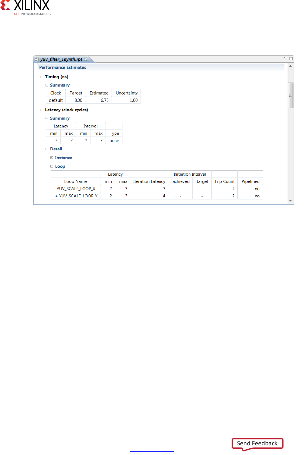
A common issue for new users of Vivado HLS is seeing a synthesis report similar to the
following figure. The latency values are all shown as a “?” (question mark).
Vivado HLS performs analysis to determine the number of iteration of each loop. If the loop
iteration limit is a variable, Vivado HLS cannot determine the maximum upper limit.
In the following example, the maximum iteration of the for-loop is determined by the value
of input num_samples. The value of num_samples is not defined in the C function, but
comes into the function from the outside.
void foo (char num_samples, ...);
void foo (num_samples, ...) {
int i;
...
loop_1: for(i=0;i< num_samples;i++) {
...
result = a + b;
}
}
If the latency or throughput of the design is dependent on a loop with a variable index,
Vivado HLS reports the latency of the loop as being unknown (represented in the reports by
a question mark “?”).
X-Ref Target - Figure 1-21
Figure 1-21: Synthesis Report
High-Level Synthesis 44
UG902 (v2017.1) April 5, 2017 www.xilinx.com
Chapter 1: High-Level Synthesis
The TRIPCOUNT directive can be applied to the loop to manually specify the number of
loop iterations and ensure the report contains useful numbers. The -max option tells
Vivado HLS the maximum number of iterations that the loop iterates over and the -min
option specifies the minimum number of iterations performed.
Note: The TRIPCOUNT directive does not impact the results of synthesis.
The tripcount values are used only for reporting, to ensure the reports generated by Vivado
HLS show meaningful ranges for latency and interval. This also allows a meaningful
comparison between different solutions.
If the C assert macro is used in the code, Vivado HLS can use it to both determine the loop
limits automatically and create hardware that is exactly sized to these limits. See Assertions
in Chapter 3 for more information.
Analysis Perspective
In addition to the synthesis report, you can use the Analysis Perspective to analyze the
results. To open the Analysis Perspective, click the Analysis button as shown in the
following figure.
The Analysis Perspective provides both a tabular and graphical view of the design
performance and resources and supports cross-referencing between both views. The
following figure shows the default window configuration when the Analysis Perspective is
first opened.
The Module Hierarchy pane provides an overview of the entire RTL design.
• This view can navigate throughout the design hierarchy.
• The Module Hierarchy pane shows the resources and latency contribution for each
block in the RTL hierarchy.
The following figure shows the dct design uses 6 block RAMs, approximately 300 LUTs and
has a latency of around 3000 clock cycles. Sub-block dct_2b contributes 4 block RAMs,
approximately 250 LUTs and about 2600 cycle of latency to the total. It is immediately clear
that most of the resources and latency in this design are due to sub-block dct_2d and this
block should be analyzed first.
X-Ref Target - Figure 1-22
Figure 1-22: Analysis Perspective
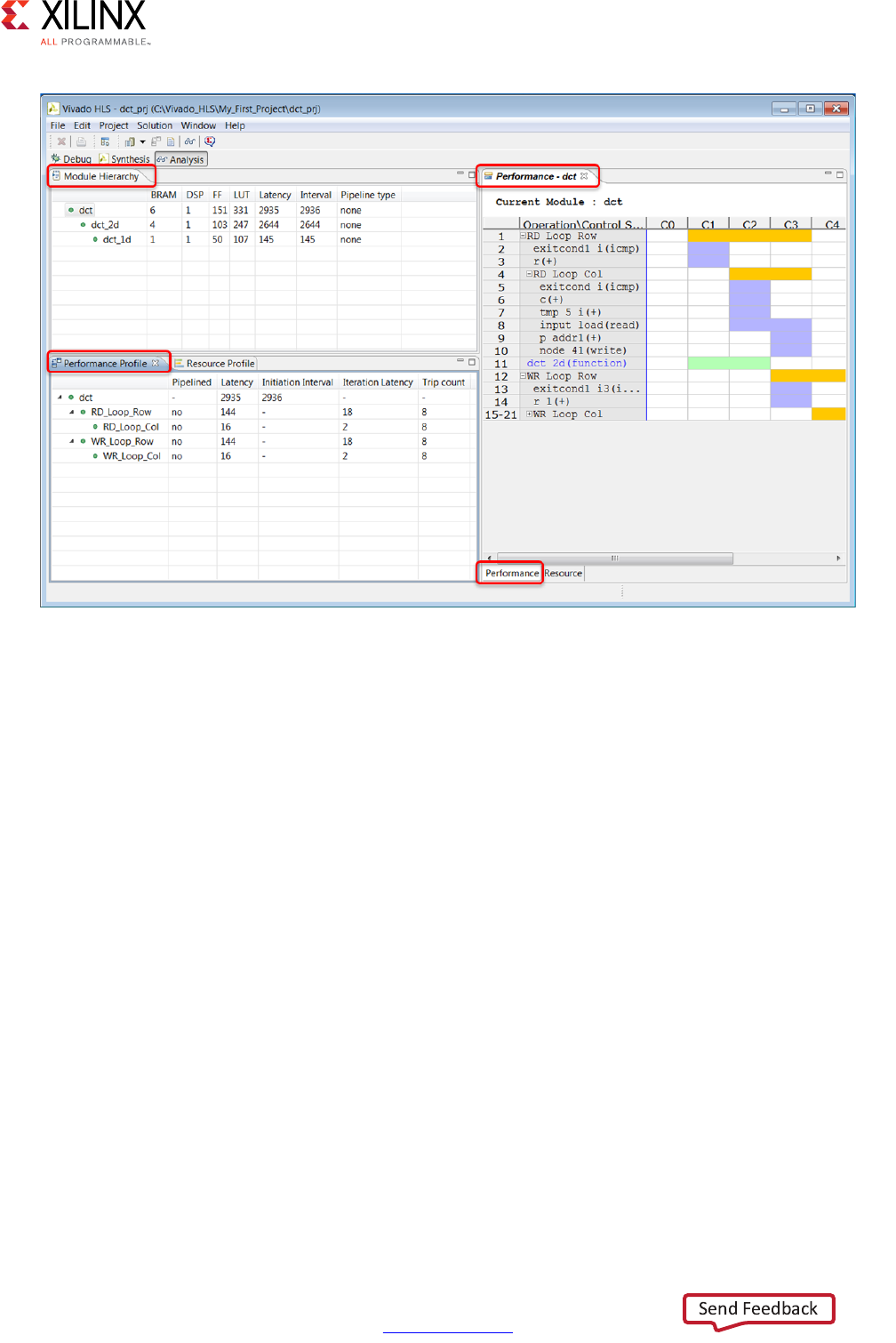
High-Level Synthesis 45
UG902 (v2017.1) April 5, 2017 www.xilinx.com
Chapter 1: High-Level Synthesis
The Performance Profile pane provides details on the performance of the block currently
selected in the Module Hierarchy pane, in this case, the dct block highlighted in the Module
Hierarchy pane.
• The performance of the block is a function of the sub-blocks it contains and any logic
within this level of hierarchy. The Performance Profile pane shows items at this level of
hierarchy that contribute to the overall performance.
• Performance is measured in terms of latency and the initiation interval. This pane also
includes details on whether the block was pipelined or not.
• In this example, you can see that two loops (RD_Loop_Row and WR_Loop_Row) are
implemented as logic at this level of hierarchy and both contain sub-loops and both
contribute 144 clock cycles to the latency. Add the latency of both loops to the latency
of dct_2d which is also inside dct and you get the total latency for the dct block.
X-Ref Target - Figure 1-23
Figure 1-23: Analysis Perspective in the Vivado HLS GUI

High-Level Synthesis 46
UG902 (v2017.1) April 5, 2017 www.xilinx.com
Chapter 1: High-Level Synthesis
The Schedule View pane shows how the operations in this particular block are scheduled
into clock cycles. The default view is the Performance view.
• The left-hand column lists the resources.
°Sub-blocks are green.
°Operations resulting from loops in the source are colored yellow.
°Standard operations are purple.
• The dct has three main resources:
°A loop called RD_Loop_Row. In Figure 1-23 the loop hierarchy for loop
RD_Loop_Row has been expanded.
°A sub-block called dct_2d.
°A loop called WR_Loop_Row. The plus symbol “+” indicates this loop has hierarchy
and the loop can be expanded to view it.
• The top row lists the control states in the design. Control states are the internal states
used by Vivado HLS to schedule operations into clock cycles. There is a close
correlation between the control states and the final states in the RTL FSM, but there is
no one-to-one mapping.
The information presented in the Schedule View is explained here by reviewing the first set
of resources to be execute: the RD_Loop_Row loop.
• The design starts in the C0 state.
• It then starts to execute the logic in loop RD_Loop_Row.
Note: In the first state of the loop, the exit condition is checked and there is an add operation.
• The loop executes over 3 states: C1, C2, and C3.
• The Performance Profile pane shows this loop has a tripcount of 8: it therefore iterates
around these 3 states 8 times.
• The Performance Profile pane shows loop RD_Loop_Rows takes 144 clock cycles to
execute.
°One cycle at the start of loop RD_Loop_Row.
°The Performance Profile pane indicates it takes 16 clock cycles to execute all
operations of loop RD_Loop_Cols.
°Plus a clock cycle to return to the start of loop RD_Loop_Row for a total of 18 cycles
per loop iteration.
°8 iterations of 18 cycles is why it takes 144 clock cycles to complete.
• Within loop RD_Loop_Col you can see there are some adders, a 2 cycle read operation
and a write operation.
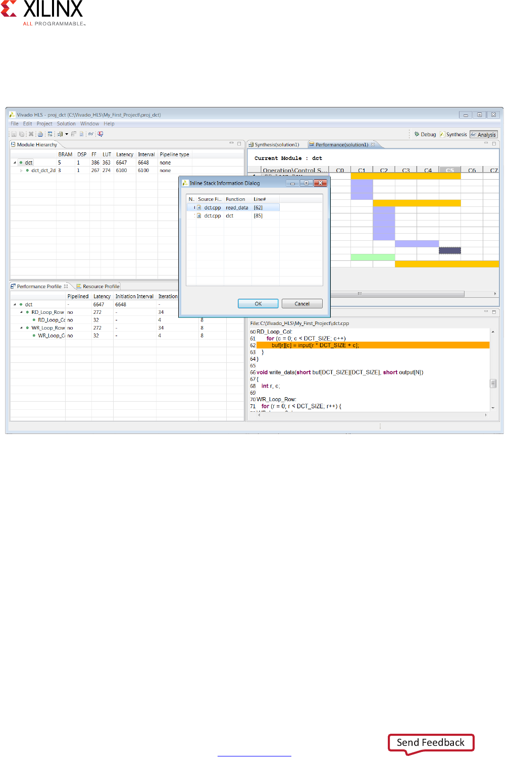
High-Level Synthesis 47
UG902 (v2017.1) April 5, 2017 www.xilinx.com
Chapter 1: High-Level Synthesis
The following figure shows that you can select an operation and right-click the mouse to
open the associated variable in the source code view. You can see that the write operation
is implementing the writing of data into the buf array from the input array variable.
X-Ref Target - Figure 1-24
Figure 1-24: C Source Code Correlation
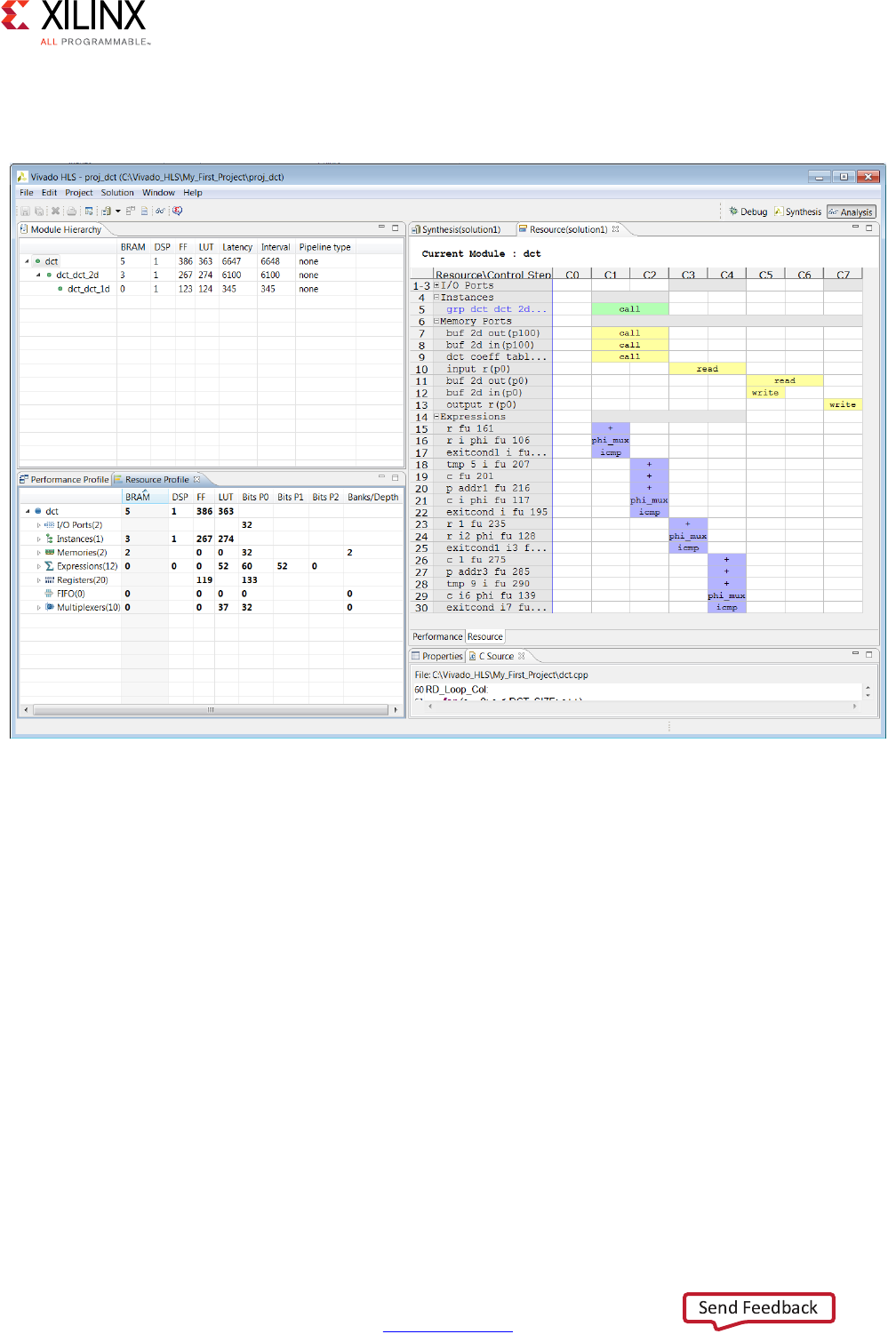
High-Level Synthesis 48
UG902 (v2017.1) April 5, 2017 www.xilinx.com
Chapter 1: High-Level Synthesis
The Analysis Perspective also allows you to analyze resource usage. The following figure
shows the resource profile and the resource panes.
The Resource Profile pane shows the resources used at this level of hierarchy. In this
example, you can see that most of the resources are due to the instances: blocks that are
instantiated inside this block.
You can see by expanding the Expressions that most of the resources at this level of
hierarchy are used to implement adders.
The Resource pane shows the control state of the operations used. In this example, all the
adder operations are associated with a different adder resource. There is no sharing of the
adders. More than one add operation on each horizontal line indicates the same resource is
used multiple times in different states or clock cycles.
The adders are used in the same cycles that are memory accessed and are dedicated to each
memory. Cross correlation with the C code can be used to confirm.
If the DATAFLOW directive has been applied to a function, the Analysis Perspective provides
a dataflow viewer which shows the structure of the design. This may be used to ensure data
flows from one task to the next.
X-Ref Target - Figure 1-25
Figure 1-25: Analysis Perspective with Resource Profile
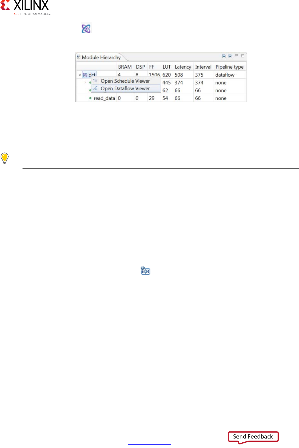
High-Level Synthesis 49
UG902 (v2017.1) April 5, 2017 www.xilinx.com
Chapter 1: High-Level Synthesis
In Figure 1-26, the icon beside the dct function indicates a dataflow view is available.
Right-click the function to open the dataflow view.
The Analysis Perspective is a highly interactive feature. More information on the Analysis
Perspective can be found in the Design Analysis section of the Vivado Design Suite Tutorial:
High-Level Synthesis (UG871) [Ref 2].
TIP: Remember, even if a Tcl flow is used to create designs, the project can still be opened in the GUI
and the Analysis Perspective used to analyze the design.
Use the Synthesis perspective button to return to the synthesis view.
Generally after design analysis you can create a new solution to apply optimization
directives. Using a new solution for this allows the different solutions to be compared.
Creating a New Solution
The most typical use of Vivado HLS is to create an initial design, then perform optimizations
to meet the desired area and performance goals. Solutions offer a convenient way to ensure
the results from earlier synthesis runs can be both preserved and compared.
Use the New Solution toolbar button or the menu Project > New Solution to create
a new solution. This opens the Solution Wizard as shown in the following figure.
X-Ref Target - Figure 1-26
Figure 1-26: Dataflow View
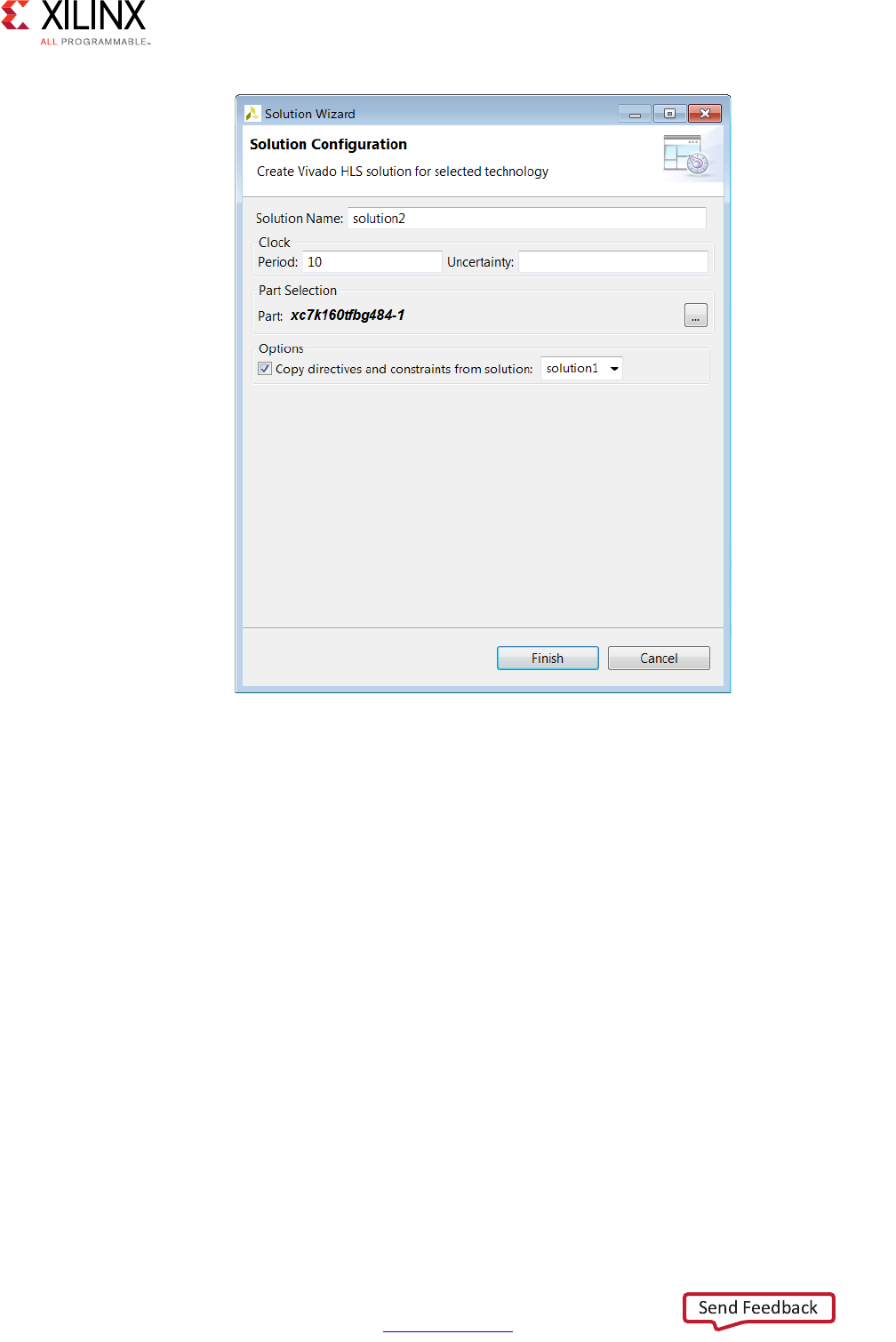
High-Level Synthesis 50
UG902 (v2017.1) April 5, 2017 www.xilinx.com
Chapter 1: High-Level Synthesis
The Solution Wizard has the same options as the final window in the New Project wizard
(Figure 1-12) plus an additional option that allow any directives and customs constraints
applied to an existing solution to be conveniently copied to the new solution, where they
can be modified or removed.
After the new solution has been created, optimization directives can be added (or modified
if they were copied from the previous solution). The next section explains how directives
can be added to solutions. Custom constraints are applied using the configuration options
and are discussed in Optimizing the Design.
Applying Optimization Directives
The first step in adding optimization directives is to open the source code in the
Information pane. As shown in the following figure, expand the Source container located at
the top of the Explorer pane, and double-click the source file to open it for editing in the
Information pane.
X-Ref Target - Figure 1-27
Figure 1-27: New Solution Wizard
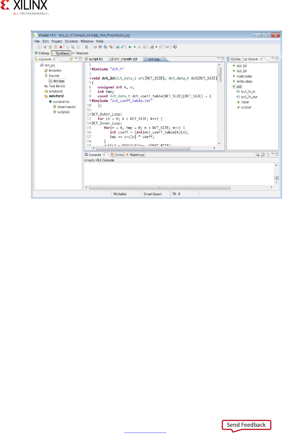
High-Level Synthesis 51
UG902 (v2017.1) April 5, 2017 www.xilinx.com
Chapter 1: High-Level Synthesis
With the source code active in the Information pane, select the Directives tab on the right
to display and modify directives for the file. The Directives tab contains all the objects and
scopes in the currently opened source code to which you can apply directives.
Note: To apply directives to objects in other C files, you must open the file and make it active in the
Information pane.
Although you can select objects in the Vivado HLS GUI and apply directives, Vivado HLS
applies all directives to the scope that contains the object. For example, you can apply an
INTERFACE directive to an interface object in the Vivado HLS GUI. Vivado HLS applies the
directive to the top-level function (scope), and the interface port (object) is identified in the
directive. In the following example, port data_in on function foo is specified as an
AXI4-Lite interface:
set_directive_interface -mode s_axilite "foo" adata_in
You can apply optimization directives to the following objects and scopes:
•Interfaces
When you apply directives to an interface, Vivado HLS applies the directive to the
top-level function, because the top-level function is the scope that contains the
interface.
X-Ref Target - Figure 1-28
Figure 1-28: Source and Directive

High-Level Synthesis 52
UG902 (v2017.1) April 5, 2017 www.xilinx.com
Chapter 1: High-Level Synthesis
• Functions
When you apply directives to functions, Vivado HLS applies the directive to all objects
within the scope of the function. The effect of any directive stops at the next level of
function hierarchy. The only exception is a directive that supports or uses a recursive
option, such as the PIPELINE directive that recursively unrolls all loops in the hierarchy.
•Loops
When you apply directives to loops, Vivado HLS applies the directive to all objects
within the scope of the loop. For example, if you apply a LOOP_MERGE directive to a
loop, Vivado HLS applies the directive to any sub-loops within the loop but not to the
loop itself.
Note: The loop to which the directive is applied is not merged with siblings at the same level of
hierarchy.
• Arrays
When you apply directives to arrays, Vivado HLS applies the directive to the scope that
contains the array.
•Regions
When you apply directives to regions, Vivado HLS applies the directive to the entire
scope of the region. A region is any area enclosed within two braces. For example:
{
the scope between these braces is a region
}
Note: You can apply directives to a region in the same way you apply directives to functions and
loops.
To apply a directive, select an object in the Directives tab, right-click, and select Insert
Directive to open the Directives Editor dialog box. From the drop-down menu, select the
appropriate directive. The drop-down menu only shows directives that you can add to the
selected object or scope. For example, if you select an array object, the drop-down menu
does not show the PIPELINE directive, because an array cannot be pipelined. The following
figure shows the addition of the DATAFLOW directive to the DCT function.
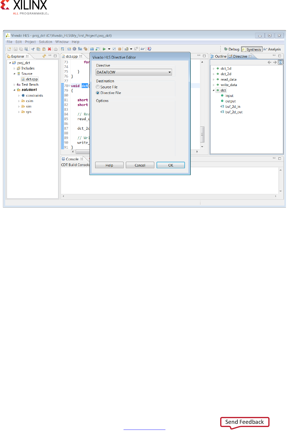
High-Level Synthesis 53
UG902 (v2017.1) April 5, 2017 www.xilinx.com
Chapter 1: High-Level Synthesis
Using Tcl Commands or Embedded Pragmas
In the Vivado HLS Directive Editor dialog box, you can specify either of the following
Destination settings:
•Directive File: Vivado HLS inserts the directive as a Tcl command into the file
directives.tcl in the solution directory.
•Source File: Vivado HLS inserts the directive directly into the C source file as a pragma.
X-Ref Target - Figure 1-29
Figure 1-29: Adding Directives

High-Level Synthesis 54
UG902 (v2017.1) April 5, 2017 www.xilinx.com
Chapter 1: High-Level Synthesis
The following table describes the advantages and disadvantages of both approaches.
The following figure shows the DATAFLOW directive being added to the Directive File. The
directives.tcl file is located in the solution constraints folder and opened in the
Information pane using the resulting Tcl command.
Table 1-2: Tcl Commands Versus Pragmas
Directive Format Advantages Disadvantages
Directives file (Tcl
Command)
• Each solution has independent
directives. This approach is ideal
for design exploration.
• If any solution is re-synthesized,
only the directives specified in
that solution are applied.
• If the C source files are transferred
to a third-party or archived, the
directives.tcl file must be
included.
•The directives.tcl file is
required if the results are to be
re-created.
Source Code (Pragma) • The optimization directives are
embedded into the C source code.
• Ideal when the C sources files are
shipped to a third-party as C IP.
No other files are required to
recreate the same results.
• Useful approach for directives
that are unlikely to change, such
as TRIPCOUNT and INTERFACE.
• If the optimization directives are
embedded in the code, they are
automatically applied to every
solution when re-synthesized.
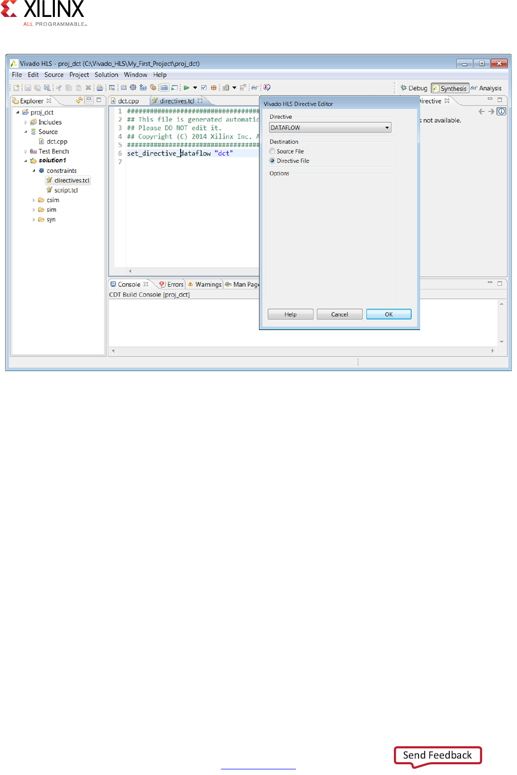
High-Level Synthesis 55
UG902 (v2017.1) April 5, 2017 www.xilinx.com
Chapter 1: High-Level Synthesis
When directives are applied as a Tcl command, the Tcl command specifies the scope or the
scope and object within that scope. In the case of loops and regions, the Tcl command
requires that these scopes be labeled. If the loop or region does not currently have a label,
a pop-up dialog box asks for a label (Assigns a default name for the label).
X-Ref Target - Figure 1-30
Figure 1-30: Adding Tcl Directives
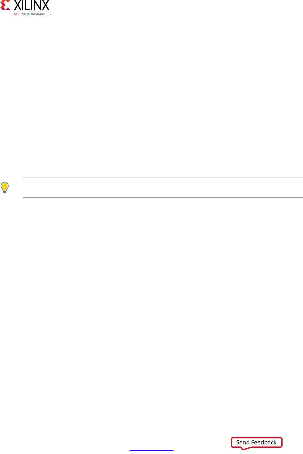
High-Level Synthesis 56
UG902 (v2017.1) April 5, 2017 www.xilinx.com
Chapter 1: High-Level Synthesis
The following shows examples of labeled and unlabeled loops and regions.
// Example of a loop with no label
for(i=0; i<3;i++ {
printf(“This is loop WITHOUT a label \n”);
}
// Example of a loop with a label
My_For_Loop:for(i=0; i<3;i++ {
printf(“This loop has the label My_For_Loop \n”);
}
// Example of an region with no label
{
printf(“The scope between these braces has NO label”);
}
// Example of a NAMED region
My_Region:{
printf(“The scope between these braces HAS the label My_Region”);
}
TIP: Named loops allow the synthesis report to be easily read. An auto-generated label is assigned to
loops without a label.
The following figure shows the DATAFLOW directive added to the Source File and the
resultant source code open in the information pane. The source code now contains a
pragma which specifies the optimization directive.
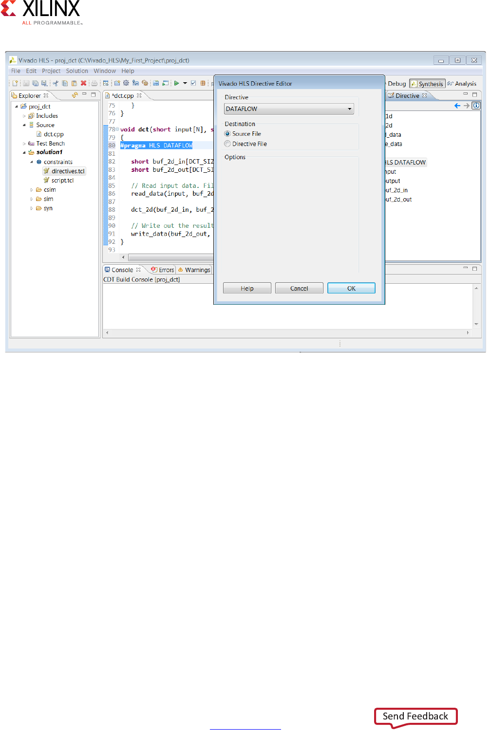
High-Level Synthesis 57
UG902 (v2017.1) April 5, 2017 www.xilinx.com
Chapter 1: High-Level Synthesis
In both cases, the directive is applied and the optimization performed when synthesis is
executed. If the code was modified, either by inserting a label or pragma, a pop-up dialog
box reminds you to save the code before synthesis.
A complete list of all directives and custom constraints can be found in Optimizing the
Design. For information on directives and custom constraints, see Chapter 4, High-Level
Synthesis Reference Guide.
Applying Optimization Directives to Global Variables
Directives can only be applied to scopes or objects within a scope. As such, they cannot be
directly applied to global variables which are declared outside the scope of any function.
To apply a directive to a global variable, apply the directive to the scope (function, loop or
region) where the global variable is used. Open the directives tab on a scope were the
variable is used, apply the directive and enter the variable name manually in Directives
Editor.
X-Ref Target - Figure 1-31
Figure 1-31: Adding Pragma Directives
High-Level Synthesis 58
UG902 (v2017.1) April 5, 2017 www.xilinx.com
Chapter 1: High-Level Synthesis
Applying Optimization Directives to Class Objects
Optimization directives can be also applied to objects or scopes defined in a class. The
difference is typically that classes are defined in a header file. Use one of the following
actions to open the header file:
• From the Explorer pane, open the Includes folder, navigate to the header file, and
double-click the file to open it.
• From within the C source, place the cursor over the header file (the #include
statement), to open hold down the Ctrl key, and click the header file.
The directives tab is then populated with the objects in the header file and directives can be
applied.
CAUTION! Care should be taken when applying directives as pragmas to a header file. The file might be
used by other people or used in other projects. Any directives added as a pragma are applied each time
the header file is included in a design.
Applying Optimization Directives to Templates
To apply optimization directives manually on templates when using Tcl commands, specify
the template arguments and class when referring to class methods. For example, given the
following C++ code:
template <uint32 SIZE, uint32 RATE>
void DES10<SIZE,RATE>::calcRUN() {…}
The following Tcl command is used to specify the INLINE directive on the function:
set_directive_inline DES10<SIZE,RATE>::calcRUN

High-Level Synthesis 59
UG902 (v2017.1) April 5, 2017 www.xilinx.com
Chapter 1: High-Level Synthesis
Using #Define with Pragma Directives
Pragma directives do not natively support the use of values specified by the define
statement. The following code seeks to specify the depth of a stream using the define
statement and will not compile.
TIP: Specify the depth argument with an explicit value.
#include <hls_stream.h>
using namespace hls;
#define STREAM_IN_DEPTH 8
void foo (stream<int> &InStream, stream<int> &OutStream) {
// Illegal pragma
#pragma HLS stream depth=STREAM_IN_DEPTH variable=InStream
// Legal pragma
#pragma HLS stream depth=8 variable=OutStream
}
You can use macros in the C code to implement this functionality. The key to using macros
is to use a level of hierarchy in the macro. This allows the expansion to be correctly
performed. The code can be made to compile as follows:
#include <hls_stream.h>
using namespace hls;
#define PRAGMA_SUB(x) _Pragma (#x)
#define PRAGMA_HLS(x) PRAGMA_SUB(x)
#define STREAM_IN_DEPTH 8
void foo (stream<int> &InStream, stream<int> &OutStream) {
// Legal pragmas
PRAGMA_HLS(HLS stream depth=STREAM_IN_DEPTH variable=InStream)
#pragma HLS stream depth=8 variable=OutStream
}

High-Level Synthesis 60
UG902 (v2017.1) April 5, 2017 www.xilinx.com
Chapter 1: High-Level Synthesis
Failure to Satisfy Optimization Directives
When optimization directives are applied, Vivado HLS outputs information to the console
(and log file) detailing the progress. In the following example the PIPELINE directives was
applied to the C function with an II=1 (iteration interval of 1) but synthesis failed to satisfy
this objective.
INFO: [SCHED 11] Starting scheduling ...
INFO: [SCHED 61] Pipelining function 'array_RAM'.
WARNING: [SCHED 63] Unable to schedule the whole 2 cycles 'load' operation
('d_i_load', array_RAM.c:98) on array 'd_i' within the first cycle (II = 1).
WARNING: [SCHED 63] Please consider increasing the target initiation interval of the
pipeline.
WARNING: [SCHED 69] Unable to schedule 'load' operation ('idx_load_2',
array_RAM.c:98) on array 'idx' due to limited memory ports.
INFO: [SCHED 61] Pipelining result: Target II: 1, Final II: 4, Depth: 6.
INFO: [SCHED 11] Finished scheduling.
IMPORTANT: If Vivado HLS fails to satisfy an optimization directive, it automatically relaxes the
optimization target and seeks to create a design with a lower performance target. If it cannot relax the
target, it will halt with an error.
By seeking to create a design which satisfies a lower optimization target, Vivado HLS is able
to provide three important types of information:
• What target performance can be achieved with the current C code and optimization
directives.
• A list of the reasons why it was unable to satisfy the higher performance target.
• A design which can be analyzed to provide more insight and help understand the
reason for the failure.
In message SCHED-69, the reason given for failing to reach the target II is due to limited
ports. The design must access a block RAM, and a block RAM only has a maximum of two
ports.
The next step after a failure such as this is to analyze what the issue is. In this example,
analyze line 52 of the code and/or use the Analysis perspective to determine the bottleneck
and if the requirement for more than two ports can be reduced or determine how the
number of ports can be increased. More details on how to optimize designs for higher
performance are provided in Optimizing the Design.
After the design is optimized and the desired performance achieved, the RTL can be verified
and the results of synthesis packaged as IP.
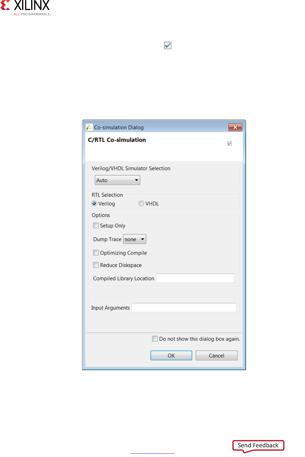
High-Level Synthesis 61
UG902 (v2017.1) April 5, 2017 www.xilinx.com
Chapter 1: High-Level Synthesis
Verifying the RTL is Correct
Use the C/RTL cosimulation toolbar button or the menu Solution > Run C/RTL
cosimulation verify the RTL results.
The C/RTL co-simulation dialog box shown in the following figure allows you to select
which type of RTL output to use for verification (Verilog or VHDL) and which HDL simulator
to use for the simulation.
A complete description of all C/RTL co-simulation options are provided in Verifying the RTL.
X-Ref Target - Figure 1-32
Figure 1-32: C/RTL Co-Simulation Dialog Box

High-Level Synthesis 62
UG902 (v2017.1) April 5, 2017 www.xilinx.com
Chapter 1: High-Level Synthesis
When verification completes, the console displays message SIM-1000 to confirm the
verification was successful. The result of any printf commands in the C test bench are
echoed to the console.
INFO: [COSIM 316] Starting C post checking ...
Test passed !
INFO: [COSIM 1000] *** C/RTL co-simulation finished: PASS ***
The simulation report opens automatically in the Information pane, showing the pass or fail
status and the measured statistics on latency and II.
IMPORTANT: The C/RTL co-simulation only passes if the C test bench returns a value of zero.
Reviewing the Output of C/RTL Co-Simulation
A sim directory is created in the solution folder when RTL verification completes. The
following figure shows the sub-folders created.
• The report folders contains the report and log file for each type of RTL simulated.
• A verification folder is created for each type of RTL which is verified. The verification
folder is named verilog or vhdl. If an RTL format is not verified, no folder is created.
• The RTL files used for simulation are stored in the verification folder.
• The RTL simulation is executed in the verification folder.
• Any outputs, such as trace files, are written to the verification folder.
•Folders autowrap, tv, wrap and wrap_pc are work folders used by Vivado HLS. There
are no user files in these folders.
If the Setup Only option was selected in the C/RTL Co-Simulation dialog boxes, an
executable is created in the verification folder but the simulation is not run. The simulation
can be manually run by executing the simulation executable at the command prompt.
Note: For more information on the RTL verification process, see Verifying the RTL.
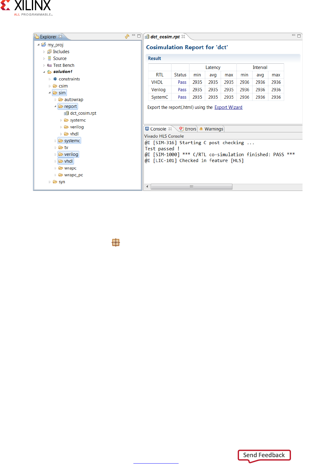
High-Level Synthesis 63
UG902 (v2017.1) April 5, 2017 www.xilinx.com
Chapter 1: High-Level Synthesis
Packaging the IP
The final step in the Vivado HLS design flow is to package the RTL output as IP. Use the
Export RTL toolbar button or the menu Solution > Export RTL to open the Export RTL
dialog box shown in the following figure.
X-Ref Target - Figure 1-33
Figure 1-33: RTL Verification Output
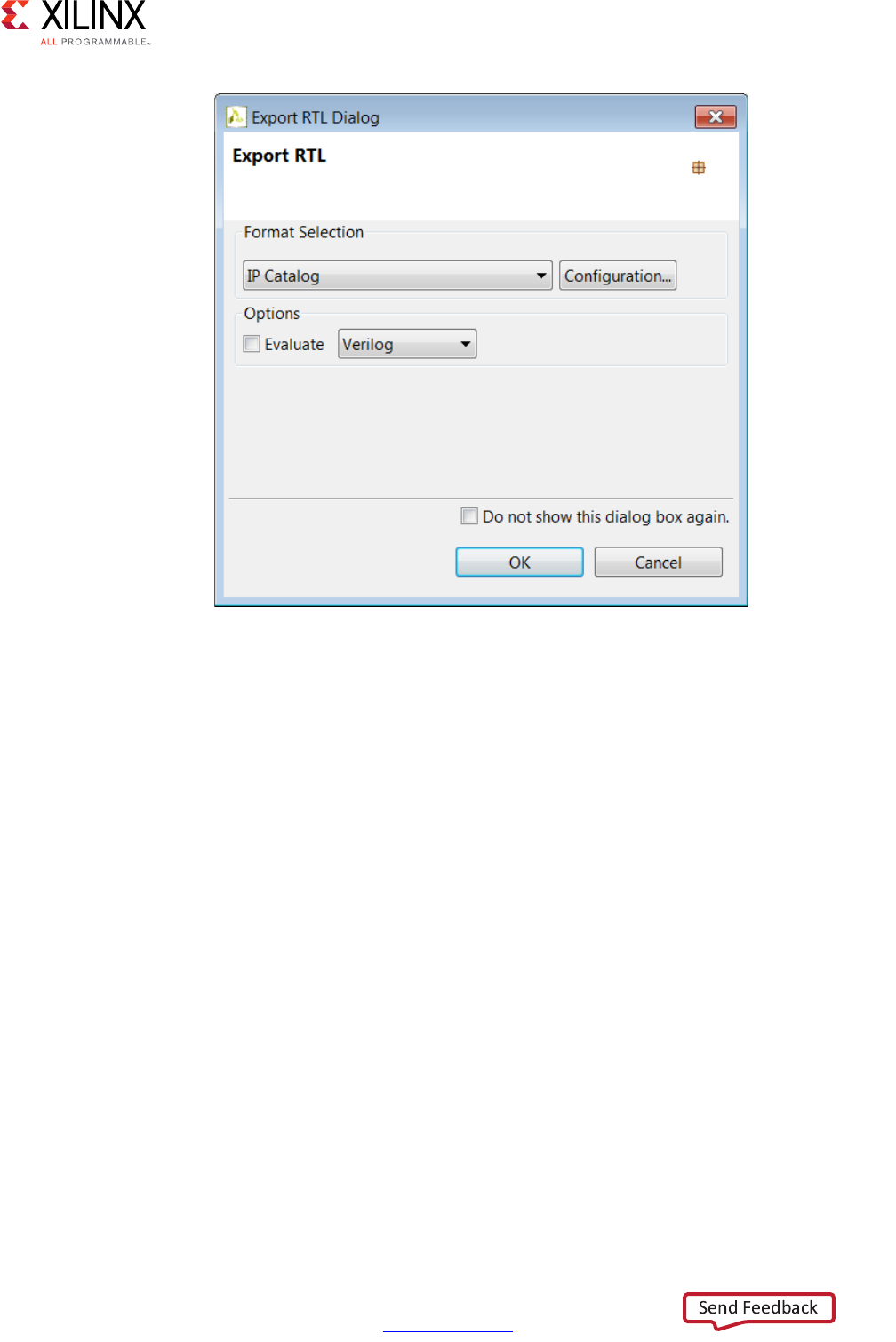
High-Level Synthesis 64
UG902 (v2017.1) April 5, 2017 www.xilinx.com
Chapter 1: High-Level Synthesis
The selections available in the drop-down Format Selection menu depend on the FPGA
device targeted for synthesis. More details on the IP packaging options is provided in
Exporting the RTL Design.
Reviewing the Output of IP Packaging
The folder impl is created in the solution folder when the Export RTL process completes.
X-Ref Target - Figure 1-34
Figure 1-34: RTL Export Dialog Box
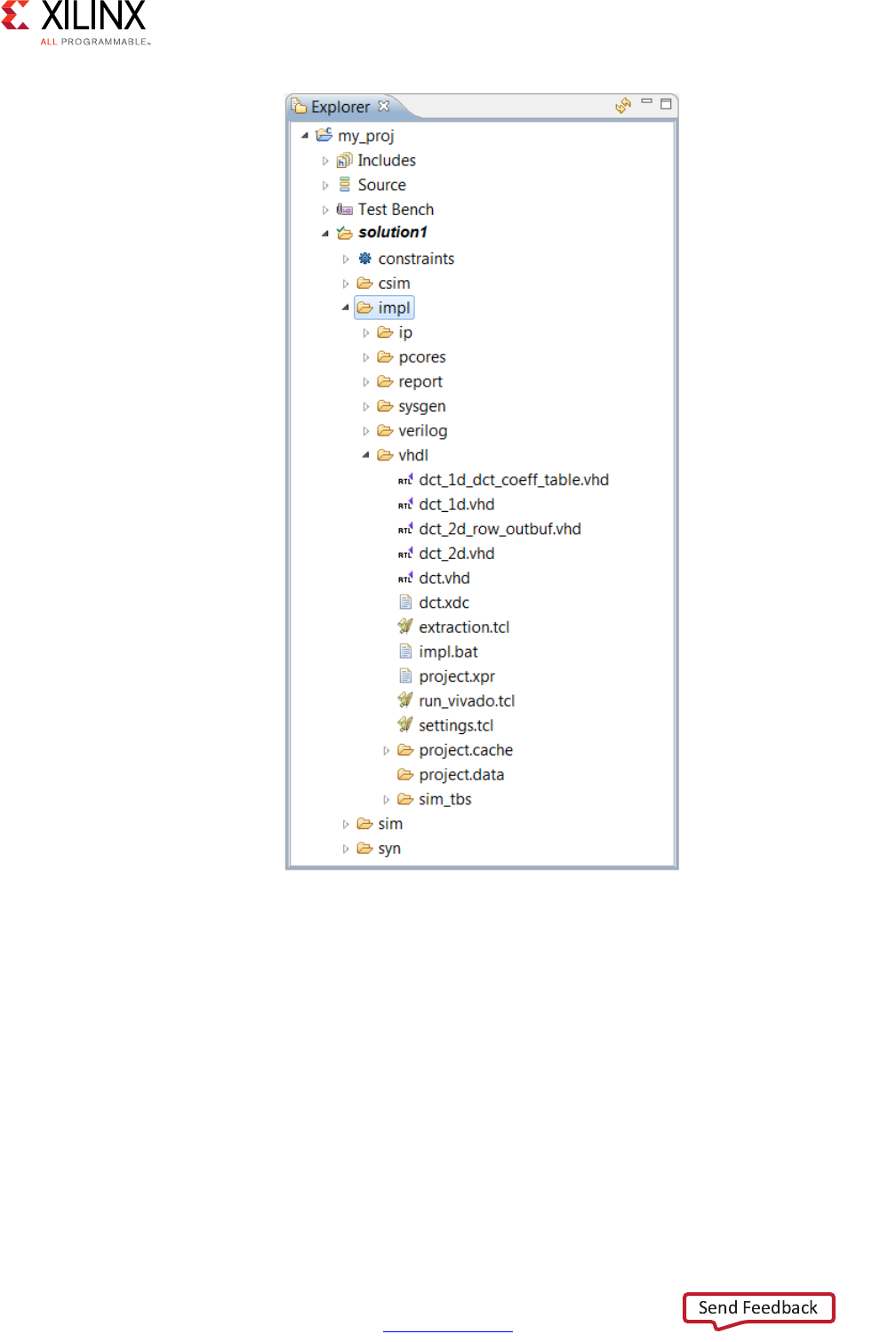
High-Level Synthesis 65
UG902 (v2017.1) April 5, 2017 www.xilinx.com
Chapter 1: High-Level Synthesis
In all cases the output includes:
•The report folder. If the flow option is selected, the report for Verilog and VHDL
synthesis or implementation is placed in this folder.
•The verilog folder. This contains the Verilog format RTL output files. If the flow
option is selected, RTL synthesis or implementation is performed in this folder.
•The vhdl folder. This contains the VHDL format RTL output files. If the flow option is
selected, RTL synthesis or implementation is performed in this folder.
X-Ref Target - Figure 1-35
Figure 1-35: Export RTL Output

High-Level Synthesis 66
UG902 (v2017.1) April 5, 2017 www.xilinx.com
Chapter 1: High-Level Synthesis
IMPORTANT: Xilinx does not recommend directly using the files in the verilog or vhdl folders for
your own RTL synthesis project. Instead, Xilinx recommends using the packaged IP output files
discussed next. Please carefully read the text that immediately follows this note.
In cases where Vivado HLS uses Xilinx IP in the design, such as with floating point designs,
the RTL directory includes a script to create the IP during RTL synthesis. If the files in the
verilog or vhdl folders are copied out and used for RTL synthesis, it is your responsibility
to correctly use any script files present in those folders. If the package IP is used, this
process is performed automatically by the design Xilinx tools.
The Format Selection drop-down determines which other folders are created. The
following formats are provided: IP Catalog, System Generator for DSP, and Synthesized
Checkpoint (.dcp). For more details, see Exporting the RTL Design.
Example Vivado RTL Project
The Export RTL process automatically creates a Vivado RTL project. For hardware designers
more familiar with RTL design and working in the Vivado RTL environment, this provides a
convenient way to analyze the RTL.
As shown in Figure 1-35 a project.xpr file is created in the verilog and vhdl folders. This
file can be used to directly open the RTL output inside the Vivado Design Suite.
Table 1-3: RTL Export Selections
Format Selection Sub-Folder Comments
IP Catalog ip Contains a ZIP file which can be added to the Vivado IP
Catalog. The ip folder also contains the contents of the
ZIP file (unzipped).
This option is not available for FPGA devices older than 7
series or Zynq-7000 AP SoC.
System Generator for DSP sysgen This output can be added to the Vivado edition of System
Generator for DSP.
This option is not available for FPGA devices older than 7
series or Zynq-7000 AP SoC.
Synthesized Checkpoint
(.dcp)
ip This option creates Vivado checkpoint files which can be
added directly into a design in the Vivado Design Suite.
This option requires RTL synthesis to be performed. When
this option is selected, the flow option and setting syn is
automatically selected.
The output includes an HDL wrapper you can use to
instantiate the IP into an HDL file.

High-Level Synthesis 67
UG902 (v2017.1) April 5, 2017 www.xilinx.com
Chapter 1: High-Level Synthesis
If C/RTL co-simulation has been executed in Vivado HLS, the Vivado project contains an RTL
test bench and the design can be simulated.
Note: The Vivado RTL project has the RTL output from Vivado HLS as the top-level design. Typically,
this design should be incorporated as IP into a larger Vivado RTL project. This Vivado project is
provided solely as a means for design analysis and is not intended as a path to implementation.
Example IP Integrator Project
If IP Catalog is selected as the output format, the output folder impl/ip/example is
created. This folder contains an executable (ipi_example.bat or ipi_example.csh) which can
be used to create a project for IP Integrator.
To create the IP Integrator project, execute the ipi_example.* file at the command
prompt then open the Vivado IPI project file which is created.
Archiving the Project
To archive the Vivado HLS project to an industry-standard ZIP file, select File > Archive.
Use the Archive Name option to name the specified ZIP file. You can modify the default
settings as follows:
• By default, only the current active solution is archived. To ensure all solutions are
archived, deselect the Active Solution Only option.
• By default, the archive contains all of the output results from the archived solutions. If
you want to archive the input files only, deselect the Include Run Results option.
Using the Command Prompt and Tcl Interface
On Windows the Vivado HLS Command Prompt can be invoked from the start menu:
Xilinx Design Tools > Vivado 2017.x > Vivado HLS > Vivado HLS 2017.x
Command Prompt.
On Windows and Linux, using the -i option with the vivado_hls command opens Vivado
HLS in interactive mode. Vivado HLS then waits for Tcl commands to be entered.
$ vivado_hls -i [-l <log_file>]
vivado_hls>
By default, Vivado HLS creates a vivado_hls.log file in the current directory. To specify
a different name for the log file, the -1 <log_file>option can be used.

High-Level Synthesis 68
UG902 (v2017.1) April 5, 2017 www.xilinx.com
Chapter 1: High-Level Synthesis
The help command is used to access documentation on the commands. A complete list of
all commands is provided using:
vivado_hls> help
Help on any individual command is provided by using the command name.
vivado_hls> help <command>
Any command or command option can be completed using the auto-complete feature.
After a single character has been specified, pressing the tab key causes Vivado HLS to list
the possible options to complete the command or command option. Entering more
characters improves the filtering of the possible options. For example, pressing the tab key
after typing “open” lists all commands that start with “open”.
vivado_hls> open <press tab key>
open
open_project
open_solution
Selecting the Tab Key after typing open_p auto-completes the command open_project,
because there are no other possible options.
Type the exit command to quit interactive mode and return to the shell prompt:
vivado_hls> exit
Additional options for Vivado HLS are:
•vivado_hls -p: open the specified project
•vivado_hls -nosplash: open the GUI without the Vivado HLS splash screen
•vivado_hls -r: return the path to the installation root directory
•vivado_hls -s: return the type of system (for example: Linux, Win)
•vivado_hls -v: return the release version number.
Commands embedded in a Tcl script are executed in batch mode with the -f
<script_file>option.
$ vivado_hls -f script.tcl
All the Tcl commands for creating a project in GUI are stored in the script.tcl file within
the solution. If you wish to develop Tcl batch scripts, the script.tcl file is an ideal
starting point.
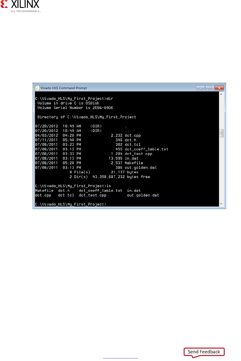
High-Level Synthesis 69
UG902 (v2017.1) April 5, 2017 www.xilinx.com
Chapter 1: High-Level Synthesis
Understanding the Windows Command Prompt
On the Windows OS, the Vivado HLS Command prompt is implemented using the
Minimalist GNU for Windows (minGW) environment, that allows both standard Windows
DOS commands to be used and/or a subset of Linux commands.
The following figure shows that both (or either) the Linux ls command and the DOS dir
command is used to list the contents of a directory.
Be aware that not all Linux commands and behaviors are supported in the minGW
environment. The following represent some known common differences in support:
• The Linux which command is not supported.
• Linux paths in a Makefile expand into minGW paths. In all Makefile files, replace any
Linux style path name assignments such as FOO := :/ with versions in which the path
name is quoted such as FOO := “:/” to prevent any path substitutions.
Improving Run Time and Capacity
If the issue is with C/RTL co-simulation, refer to the reduce_diskspace option discussed
in Verifying the RTL. The remainder of this section reviews issues with synthesis run time.
X-Ref Target - Figure 1-36
Figure 1-36: Vivado HLS Command Prompt

High-Level Synthesis 70
UG902 (v2017.1) April 5, 2017 www.xilinx.com
Chapter 1: High-Level Synthesis
Vivado HLS schedules operations hierarchically. The operations within a loop are scheduled,
then the loop, the sub-functions and operations with a function are scheduled. Run time for
Vivado HLS increases when:
• There are more objects to schedule.
• There is more freedom and more possibilities to explore.
Vivado HLS schedules objects. Whether the object is a floating-point multiply operation or
a single register, it is still an object to be scheduled. The floating-point multiply may take
multiple cycles to complete and use many resources to implement but at the level of
scheduling it is still one object.
Unrolling loops and partitioning arrays creates more objects to schedule and potentially
increases the run time. Inlining functions creates more objects to schedule at this level of
hierarchy and also increases run time. These optimizations may be required to meet
performance but be very careful about simply partitioning all arrays, unrolling all loops and
inlining all functions: you can expect a run time increase. Use the optimization strategies
provided earlier and judiciously apply these optimizations.
If the arrays must be partitioned to achieve performance, consider using the
throughput_driven option for config_array_partition to only partition the arrays
based on throughput requirements.
If the loops must be unrolled, or if the use of the PIPELINE directive in the hierarchy above
has automatically unrolled the loops, consider capturing the loop body as a separate
function. This will capture all the logic into one function instead of creating multiple copies
of the logic when the loop is unrolled: one set of objects in a defined hierarchy will be
scheduled faster. Remember to pipeline this function if the unrolled loop is used in
pipelined region.
The degrees of freedom in the code can also impact run time. Consider Vivado HLS to be an
expert designer who by default is given the task of finding the design with the highest
throughput, lowest latency and minimum area. The more constrained Vivado HLS is, the
fewer options it has to explore and the faster it will run. Consider using latency constraints
over scopes within the code: loops, functions or regions. Setting a LATENCY directive with
the same minimum and maximum values reduces the possible optimization searches within
that scope.
Finally, the config_schedule configuration controls the effort level used during
scheduling. This generally has less impact than the techniques mentioned above, but it is
worth considering. The default strategy is set to Medium.
If this setting is set to Low, Vivado HLS will reduce the amount of time it spends on trying
to improve on the initial result. In some cases, especially if there are many operations and
hence combinations to explore, it may be worth using the low setting. The design may not
be ideal but it may satisfy the requirements and be very close to the ideal. You can proceed

High-Level Synthesis 71
UG902 (v2017.1) April 5, 2017 www.xilinx.com
Chapter 1: High-Level Synthesis
to make progress with the low setting and then use the default setting before you create
your final result.
With a run strategy set to High, Vivado HLS uses additional CPU cycles and memory, even
after satisfying the constraints, to determine if it can create an even smaller or faster design.
This exploration may, or may not, result in a better quality design but it does take more time
and memory to complete. For designs that are just failing to meet their goals or for designs
where many different optimization combinations are possible, this could be a useful
strategy. In general, it is a better practice to leave the run strategies at the Medium default
setting.
Design Examples and References
Vivado HLS provides many tutorials and design examples.
Tutorials
Tutorials are available in the Vivado Design Suite Tutorial: High-Level Synthesis (UG871)
[Ref 2]. The following table shows a list of the tutorial exercises.
Table 1-4: Vivado HLS Tutorial Exercises
Tutorial Exercise Description
Vivado HLS Introductory
Tutorial
An introduction to the operation and primary features of Vivado HLS using
an FIR design.
C Validation This tutorial uses a Hamming window design to explain C simulation and
using the C debug environment to validate your C algorithm.
Interface Synthesis Exercises on how to create various types of RTL interface ports using
interface synthesis.
Arbitrary Precision Types Shows how a floating-point winding function is implemented using
fixed-point arbitrary precision types to produce more optimal hardware.
Design Analysis Shows how the Analysis perspective is used to improve the performance of
a DCT block.
Design Optimization Uses a matrix multiplication example to show how an algorithm in
optimized. This tutorial demonstrates how changes to the initial might be
required for a specific hardware implementation.
RTL Verification How to use the RTL verification features and analyze the RTL signals
waveforms.
Using HLS IP in IP
Integrator
Shows how two HLS pre and post processing blocks for an FFT can be
connected to an FFT IP block using IP integrator.
Using HLS IP in a
Zynq-7000 AP SoC
Processor Design
Shows how the CPU can be used to control a Vivado HLS block through the
AXI4-Lite interface and DMA streaming data from DDR memory to and
from a Vivado HLS block. Includes the CPU source code and required steps
in SDK.
Using HLS IP in System
Generator for DSP
A tutorial on how to use an HLS block and inside a System Generator for
DSP design.

High-Level Synthesis 72
UG902 (v2017.1) April 5, 2017 www.xilinx.com
Chapter 1: High-Level Synthesis
Design Examples
To open the Vivado HLS design examples from the Welcome Page, click Open Example
Project. In the Examples wizard, select a design from the Design Examples folder.
Note: The Welcome Page appears when you invoke the Vivado HLS GUI. You can access it at any
time by selecting Help > Welcome.
You can also open the design examples directly from the Vivado Design Suite installation
area: Vivado_HLS\2017.x\examples\design.
The following table provides a description for each design example.
Table 1-5: Vivado HLS Design Examples
Design Example Description
2D_convolution_with_linebuffer 2D convolution implemented using hls::streams and a line
buffer to conserve resources.
FFT > fft_ifft Inverse FFT using FFT IP.
FFT > fft_single Single 1024 point forward FFT with pipelined streaming I/O.
FIR > fir_2ch_int FIR filter with 2 interleaved channels.
FIR > fir_3stage FIR chain with 3 FIRs connected in series: Half band FIR to
Half band FIR to a square root raise cosine (SRRC) FIR.
FIR > fir_config FIR filter with coefficients updated using the FIR CONFIG
channel.
FIR > fir_srrc SRRC FIR filter.
__builtin_ctz Priority encoder (32- and 64-bit versions) implemented
using gcc built-in ‘count trailing zero’ function.
axi_lite AXI4-Lite interface.
axi_master AXI4 master interface.
axi_stream_no_side_channel_data AXI4-Stream interface with no side-channel data in the C
code.
axi_stream_side_channel_data AXI4-Stream interfaces using side-channel data.
dds > dds_mode_fixed DDS IP created with both phase offset and phase increment
used in fixed mode.
dds > dds_mode_none DDS IP created with phase offset in fixed mode and no phase
increment (mode=none).
dsp > atan2 arctan function from the HLS DSP library.
dsp > awgn Additive white Gaussian noise (awgn) function from the HLS
DSP library.
dsp > cmpy_complex Fixed-point complex multiplier using complex data types.
dsp > cmpy_scalar Fixed-point complex multiplier using separate scalar data
types for the real and imaginary components.

High-Level Synthesis 73
UG902 (v2017.1) April 5, 2017 www.xilinx.com
Chapter 1: High-Level Synthesis
dsp > convolution_encoder Convolution_encoder function from the HLS DSP library,
which performs convolutional encoding of an input data
stream based on user-defined convolution codes and
constraint length.
dsp > nco Numerically controlled oscillator (NCO) function from the
HLS DSP library.
dsp > qam_demod QAM demodulator function from the HLS DSP library.
dsp > qam_mod QAM modulator function from the HLS DSP library.
dsp > sqrt Fixed-point coordinate rotation digital computer (CORDIC)
implementation of the square root function from the HLS
DSP library.
dsp > viterbi_decoder Viterbi decoder from the HLS DSP library.
fp_mul_pow2 Efficient (area and timing) floating point multiplication
implementation using power-of-two, which uses a small
adder and some optional limit checks instead of a
floating-point core and DSP resources.
fxp_sqrt Square-root implementation for ap_fixed types
implemented in a bit-serial, fully pipelineable manner.
hls_stream Multirate dataflow (8-bit I/O, 32-bit data processing and
decimation) design using hls::stream.
linear_algebra > cholesky Parameterized Cholesky function.
linear_algebra > cholesky_alt Alternative Cholesky implementation.
linear_algebra > cholesky_alt_inverse Cholesky function with a customized trait class to select
different implementations.
linear_algebra > cholesky_complex Cholesky function with a complex data type.
linear_algebra > cholesky_inverse Parameterized Cholesky Inverse function.
linear_algebra > implementation_targets Implementation target examples.
Note: For details, see Optimizing the Linear Algebra Functions in
Chapter 2.
linear_algebra > matrix_multiply Parameterized matrix multiply function.
linear_algebra > matrix_multiply_alt Alternative matrix multiply function.
linear_algebra > qr_inverse Parameterized QR Inverse function.
linear_algebra > qrf Parameterized QRF function.
linear_algebra > qrf_alt Alternative parameterized QRF function.
linear_algebra > svd Parameterized SVD function.
linear_algebra > svd_pairs Parameterized SVD function with alternative “pairs” SVD
implementation.
loop_labels > loop_label Loop with a label.
loop_labels > no_loop_label Loop without a label.
Table 1-5: Vivado HLS Design Examples (Cont’d)
Design Example Description
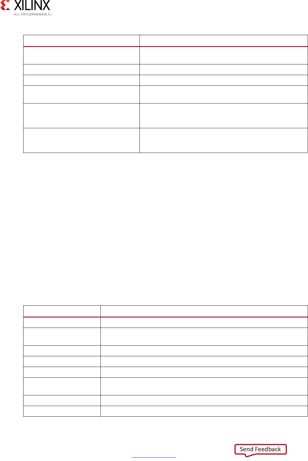
High-Level Synthesis 74
UG902 (v2017.1) April 5, 2017 www.xilinx.com
Chapter 1: High-Level Synthesis
Coding Examples
The Vivado HLS coding examples provide examples of various coding techniques. These are
small examples intended to highlight the results of Vivado HLS synthesis on various C, C++,
and SystemC constructs.
To open the Vivado HLS coding examples from the Welcome Page, click Open Example
Project. In the Examples wizard, select a design from the Coding Style Examples folder.
Note: The Welcome Page appears when you invoke the Vivado HLS GUI. You can access it at any
time by selecting Help > Welcome.
You can also open the design examples directly from the Vivado Design Suite installation
area: Vivado_HLS\2017.x\examples\coding.
The following table provides a description for each coding example.
memory_porting_and_ii Initiation interval improved using array partitioning
directives.
perfect_loop > perfect Perfect loop.
perfect_loop > semi_perfect Semi-perfect loop.
rom_init_c Array coded using a sub-function to guarantee a ROM
implementation.
window_fn_float Single-precision floating point windowing function. C++
template class example with compile time selection between
Rectangular (none), Hann, Hamming, or Gaussian windows.
window_fn_fxpt Fixed-point windowing function. C++ template class
example with compile time selection between Rectangular
(none), Hann, Hamming, or Gaussian windows.
Table 1-6: Vivado HLS Coding Examples
Coding Example Description
apint_arith Using C ap_cint types.
apint_promotion Highlights the casting required to avoid integer promotion issues with C
ap_cint types.
array_arith Using arithmetic in interface arrays.
array_FIFO Implementing a FIFO interface.
array_mem_bottleneck Demonstrates how access to arrays can create a performance bottleneck.
array_mem_perform A solution for the performance bottleneck shown by example
array_mem_bottleneck.
array_RAM Implementing a block RAM interface.
array_ROM Example demonstrating how a ROM is automatically inferred.
Table 1-5: Vivado HLS Design Examples (Cont’d)
Design Example Description

High-Level Synthesis 75
UG902 (v2017.1) April 5, 2017 www.xilinx.com
Chapter 1: High-Level Synthesis
array_ROM_math_init Example demonstrating how to infer a ROM in more complex cases.
cpp_ap_fixed Using C++ ap_int types.
cpp_ap_int_arith Using C++ ap_int types for arithmetic.
cpp_FIR An example C++ design using object orientated coding style.
cpp_math An example floating point math design that shows how to use a tolerance
in the test bench when comparing results for operations that are not IEEE
exact.
cpp_template C++ template example.
func_sized Fixing the size of operation by defining the data widths at the interface.
hier_func An example of adding files as test bench and design files.
hier_func2 An example of adding files as test bench and design files. An example of
synthesizing a lower-level block in the hierarchy.
hier_func3 An example of combining test bench and design functions into the same
file.
hier_func4 Using the pre-defined macro __SYNTHESIS__ to prevent code being
synthesized.
Note: Only use the __SYNTHESIS__ macro in the code to be synthesized. Do not use
this macro in the test bench, because it is not obeyed by C simulation or C RTL
co-simulation.
loop_functions Converting loops into functions for parallel execution.
loop_imperfect An imperfect loop example.
loop_max_bounds Using a maximum bounds to allow loops be unrolled.
loop_perfect An perfect loop example.
loop_pipeline Example of loop pipelining.
loop_sequential Sequential loops.
loop_sequential_assert Using assert statements.
loop_var A loop with variable bounds.
malloc_removed Example on removing mallocs from the code.
opencl_kernel Example of synthesizing an OpenCL API C kernel using Vivado HLS,
including the implementation of the test bench for verification.
pointer_arith Pointer arithmetic example.
pointer_array An array of pointers.
pointer_basic Basic pointer example.
pointer_cast_native Pointer casting between native C types.
pointer_double Pointer-to-Pointer example.
pointer_multi An example of using multiple pointer targets.
pointer_stream_better Example showing how the volatile keyword is used on interfaces.
pointer_stream_good Multi-read pointer example using explicit pointer arithmetic.
Table 1-6: Vivado HLS Coding Examples (Cont’d)
Coding Example Description
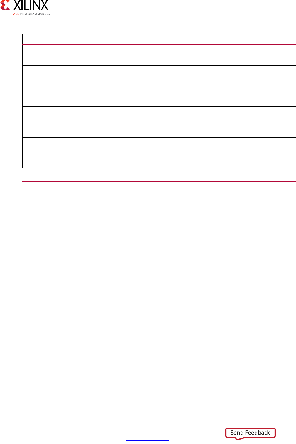
High-Level Synthesis 76
UG902 (v2017.1) April 5, 2017 www.xilinx.com
Chapter 1: High-Level Synthesis
Data Types for Efficient Hardware
C-based native data types are all on 8-bit boundaries (8, 16, 32, 64 bits). RTL buses
(corresponding to hardware) support arbitrary data lengths. Using the standard C data
types can result in inefficient hardware. For example the basic multiplication unit in an FPGA
is the DSP48 macro. This provides a multiplier which is 18*18-bit. If a 17-bit multiplication
is required, you should not be forced to implement this with a 32-bit C data type: this would
require 3 DSP48 macros to implement a multiplier when only 1 is required.
The advantage of arbitrary precision data types is that they allow the C code to be updated
to use variables with smaller bit-widths and then for the C simulation to be re-executed to
validate the functionality remains identical or acceptable. The smaller bit-widths result in
hardware operators which are in turn smaller and faster. This is in turn allows more logic to
be place in the FPGA and for the logic to execute at higher clock frequencies.
sc_combo_method SystemC combinational design example.
sc_FIFO_port SystemC FIFO port example.
sc_multi_clock SystemC example with multiple clocks.
sc_RAM_port SystemC block RAM port example.
sc_sequ_cthread SystemC sequential design example.
struct_port Using structs on the interface.
sum_io Example of top-level interface ports.
types_composite Composite types.
types_float_double Float types to double type conversion.
types_global Using global variables.
types_standard Example with standard C types.
types_union Example with unions.
Table 1-6: Vivado HLS Coding Examples (Cont’d)
Coding Example Description

High-Level Synthesis 77
UG902 (v2017.1) April 5, 2017 www.xilinx.com
Chapter 1: High-Level Synthesis
Advantages of Hardware Efficient Data Types
The following code performs some basic arithmetic operations:
#include "types.h"
void apint_arith(dinA_t inA, dinB_t inB, dinC_t inC, dinD_t inD,
dout1_t *out1, dout2_t *out2, dout3_t *out3, dout4_t *out4
) {
// Basic arithmetic operations
*out1 = inA * inB;
*out2 = inB + inA;
*out3 = inC / inA;
*out4 = inD % inA;
}
The data types dinA_t, dinB_t etc. are defined in the header file types.h. It is highly
recommended to use a project wide header file such as types.h as this allows for the easy
migration from standard C types to arbitrary precision types and helps in refining the
arbitrary precision types to the optimal size.
If the data types in the above example are defined as:
typedef char dinA_t;
typedef short dinB_t;
typedef int dinC_t;
typedef long long dinD_t;
typedef int dout1_t;
typedef unsigned int dout2_t;
typedef int32_t dout3_t;
typedef int64_t dout4_t;

High-Level Synthesis 78
UG902 (v2017.1) April 5, 2017 www.xilinx.com
Chapter 1: High-Level Synthesis
The design gives the following results after synthesis:
+ Timing (ns):
* Summary:
+---------+-------+----------+------------+
| Clock | Target| Estimated| Uncertainty|
+---------+-------+----------+------------+
|default | 4.00| 3.85| 0.50|
+---------+-------+----------+------------+
+ Latency (clock cycles):
* Summary:
+-----+-----+-----+-----+---------+
| Latency | Interval | Pipeline|
| min | max | min | max | Type |
+-----+-----+-----+-----+---------+
| 66| 66| 67| 67| none |
+-----+-----+-----+-----+---------+
* Summary:
+-----------------+---------+-------+--------+--------+
| Name | BRAM_18K| DSP48E| FF | LUT |
+-----------------+---------+-------+--------+--------+
|Expression | -| -| 0| 17|
|FIFO | -| -| -| -|
|Instance | -| 1| 17920| 17152|
|Memory | -| -| -| -|
|Multiplexer | -| -| -| -|
|Register | -| -| 7| -|
+-----------------+---------+-------+--------+--------+
|Total | 0| 1| 17927| 17169|
+-----------------+---------+-------+--------+--------+
|Available | 650| 600| 202800| 101400|
+-----------------+---------+-------+--------+--------+
|Utilization (%) | 0| ~0 | 8| 16|
+-----------------+---------+-------+--------+--------+
If the width of the data is not required to be implemented using standard C types but in
some width which is smaller, but still greater than the next smallest standard C type, such as
the following,
typedef int6 dinA_t;
typedef int12 dinB_t;
typedef int22 dinC_t;
typedef int33 dinD_t;
typedef int18 dout1_t;
typedef uint13 dout2_t;
typedef int22 dout3_t;
typedef int6 dout4_t;

High-Level Synthesis 79
UG902 (v2017.1) April 5, 2017 www.xilinx.com
Chapter 1: High-Level Synthesis
The results after synthesis shown an improvement to the maximum clock frequency, the
latency and a significant reduction in area of 75%.
+ Timing (ns):
* Summary:
+---------+-------+----------+------------+
| Clock | Target| Estimated| Uncertainty|
+---------+-------+----------+------------+
|default | 4.00| 3.49| 0.50|
+---------+-------+----------+------------+
+ Latency (clock cycles):
* Summary:
+-----+-----+-----+-----+---------+
| Latency | Interval | Pipeline|
| min | max | min | max | Type |
+-----+-----+-----+-----+---------+
| 35| 35| 36| 36| none |
+-----+-----+-----+-----+---------+
* Summary:
+-----------------+---------+-------+--------+--------+
| Name | BRAM_18K| DSP48E| FF | LUT |
+-----------------+---------+-------+--------+--------+
|Expression | -| -| 0| 13|
|FIFO | -| -| -| -|
|Instance | -| 1| 4764| 4560|
|Memory | -| -| -| -|
|Multiplexer | -| -| -| -|
|Register | -| -| 6| -|
+-----------------+---------+-------+--------+--------+
|Total | 0| 1| 4770| 4573|
+-----------------+---------+-------+--------+--------+
|Available | 650| 600| 202800| 101400|
+-----------------+---------+-------+--------+--------+
|Utilization (%) | 0| ~0 | 2| 4|
+-----------------+---------+-------+--------+--------+
The large difference in latency between both design is due to the division and remainder
operations which take multiple cycles to complete. Using accurate data types, rather than
force fitting the design into standard C data types, results in a higher quality FPGA
implementation: the same accuracy, running faster with less resources.

High-Level Synthesis 80
UG902 (v2017.1) April 5, 2017 www.xilinx.com
Chapter 1: High-Level Synthesis
Overview of Arbitrary Precision Integer Data Types
Vivado HLS provides integer and fixed-point arbitrary precision data types for C, C++ and
supports the arbitrary precision data types that are part of SystemC.
The header files which define the arbitrary precision types are also provided with Vivado
HLS as a standalone package with the rights to use them in your own source code. The
package, xilinx_hls_lib_<release_number>.tgz is provided in the include
directory in the Vivado HLS installation area. The package does not include the C arbitrary
precision types defined in ap_cint.h. These types cannot be used with standard C
compilers - only with Vivado HLS.
Arbitrary Precision Integer Types with C
For the C language, the header file ap_cint.h defines the arbitrary precision integer data
types [u]int. To use arbitrary precision integer data types in a C function:
• Add header file ap_cint.h to the source code.
• Change the bit types to intN or uintN, where N is a bit-size from 1 to 1024.
Arbitrary Precision Types with C++
For the C++ language ap_[u]int data types the header file ap_int.h defines the
arbitrary precision integer data type. To use arbitrary precision integer data types in a C++
function:
• Add header file ap_int.h to the source code.
• Change the bit types to ap_int<N> or ap_uint<N>, where N is a bit-size from 1 to
1024.
Table 1-7: Arbitrary Precision Data Types
Language Integer Data Type Required Header
C [u]int<W> (1024 bits) #include “ap_cint.h”
C++ ap_[u]int<W> (1024 bits)
Can be extended to 32K bits wide.
#include “ap_int.h”
C++ ap_[u]fixed<W,I,Q,O,N> #include “ap_fixed.h”
System C sc_[u]int<W> (64 bits)
sc_[u]bigint<W> (512 bits)
#include “systemc.h”
System C sc_[u]fixed<W,I,Q,O,N> #define SC_INCLUDE_FX
[#define SC_FX_EXCLUDE_OTHER]
#include “systemc.h”
High-Level Synthesis 81
UG902 (v2017.1) April 5, 2017 www.xilinx.com
Chapter 1: High-Level Synthesis
The following example shows how the header file is added and two variables implemented
to use 9-bit integer and 10-bit unsigned integer types:
#include "ap_int.h"
void foo_top (…) {
ap_int<9> var1; // 9-bit
ap_uint<10> var2; // 10-bit unsigned
The default maximum width allowed for ap_[u]int data types is 1024 bits. This default
may be overridden by defining the macro AP_INT_MAX_W with a positive integer value less
than or equal to 32768 before inclusion of the ap_int.h header file.
CAUTION! Setting the value of AP_INT_MAX_W too High may cause slow software compile and run
times.
Following is an example of overriding AP_INT_MAX_W:
#define AP_INT_MAX_W 4096 // Must be defined before next line
#include "ap_int.h"
ap_int<4096> very_wide_var;
Arbitrary Precision Types with SystemC
The arbitrary precision types used by SystemC are defined in the systemc.h header file
that is required to be included in all SystemC designs. The header file includes the SystemC
sc_int<>, sc_uint<>, sc_bigint<> and sc_biguint<> types.
Overview of Arbitrary Precision Fixed-Point Data Types
Fixed-point data types model the data as an integer and fraction bits. In this example the
Vivado HLS ap_fixed type is used to define an 18-bit variable with 6 bits representing the
numbers above the binary point and 12-bits representing the value below the decimal
point. The variable is specified as signed, the quantization mode is set to round to plus
infinity. Since the overflow mode is not specified, the default wrap-around mode is used for
overflow.
#include <ap_fixed.h>
...
ap_fixed<18,6,AP_RND > my_type;
...
When performing calculations where the variables have different number of bits or different
precision, the binary point is automatically aligned.
The behavior of the C++/SystemC simulations performed using fixed-point matches the
resulting hardware. This allows you to analyze the bit-accurate, quantization, and overflow
behaviors using fast C-level simulation.

High-Level Synthesis 82
UG902 (v2017.1) April 5, 2017 www.xilinx.com
Chapter 1: High-Level Synthesis
Fixed-point types are a useful replacement for floating point types which require many
clock cycle to complete. Unless the entire range of the floating-point type is required, the
same accuracy can often be implemented with a fixed-point type resulting in the same
accuracy with smaller and faster hardware.
A summary of the ap_fixed type identifiers is provided in the following table.
The default maximum width allowed for ap_[u]fixed data types is 1024 bits. This default
may be overridden by defining the macro AP_INT_MAX_W with a positive integer value less
than or equal to 32768 before inclusion of the ap_int.h header file.
Table 1-8: Fixed-Point Identifier Summary
Identifier Description
WWord length in bits
IThe number of bits used to represent the integer value (the number of bits above the
binary point)
QQuantization mode
This dictates the behavior when greater precision is generated than can be defined by
smallest fractional bit in the variable used to store the result.
SystemC Types ap_fixed Types Description
SC_RND AP_RND Round to plus infinity
SC_RND_ZERO AP_RND_ZERO Round to zero
SC_RND_MIN_INF AP_RND_MIN_INF Round to minus infinity
SC_RND_INF AP_RND_INF Round to infinity
SC_RND_CONV AP_RND_CONV Convergent rounding
SC_TRN AP_TRN Truncation to minus infinity
(default)
SC_TRN_ZERO AP_TRN_ZERO Truncation to zero
OOverflow mode.
This dictates the behavior when the result of an operation exceeds the maximum (or
minimum in the case of negative numbers) value which can be stored in the result variable.
SystemC Types ap_fixed Types Description
SC_SAT AP_SAT Saturation
SC_SAT_ZERO AP_SAT_ZERO Saturation to zero
SC_SAT_SYM AP_SAT_SYM Symmetrical saturation
SC_WRAP AP_WRAP Wrap around (default)
SC_WRAP_SM AP_WRAP_SM Sign magnitude wrap
around
NThis defines the number of saturation bits in the overflow wrap modes.

High-Level Synthesis 83
UG902 (v2017.1) April 5, 2017 www.xilinx.com
Chapter 1: High-Level Synthesis
CAUTION! Setting the value of AP_INT_MAX_W too High may cause slow software compile and run
times.
Following is an example of overriding AP_INT_MAX_W:
#define AP_INT_MAX_W 4096 // Must be defined before next line
#include "ap_fixed.h"
ap_fixed<4096> very_wide_var;
Arbitrary precision data types are highly recommend when using Vivado HLS. As shown in
the earlier example, they typically have a significant positive benefit on the quality of the
hardware implementation. Complete details on the Vivado HLS arbitrary precision data
types are provided in the Chapter 4, High-Level Synthesis Reference Guide.
Half-Precision Floating-Point Data Types
Vivado HLS provides a half-precision (16-bit) floating-point data type. This data type
provides many of the advantages of standard C float types but uses fewer hardware
resources when synthesized. The half-precision floating-point data type provides a smaller
dynamic range than the standard 32-bit float type. From the MSB to the LSB, the
half-precision floating-point data type provides the following:
•1 signed bit
• 5 exponent bits
• 10 mantissa bits
The following example shows how Vivado HLS uses the half-precision floating-point data
type:
// Include half-float header file
#include “hls_half.h”
// Use data-type “half”
typedef half data_t;
// Use typedef or “half” on arrays and pointers
void top( data_t in[SIZE], half &out_sum);
Vivado HLS supports the following arithmetic operations for the half-precision
floating-point data type:
• Addition
• Division
•Multiplication
•Subtraction

High-Level Synthesis 84
UG902 (v2017.1) April 5, 2017 www.xilinx.com
Chapter 1: High-Level Synthesis
For details on the arithmetic operations supported for half-precision floating-point data
types, refer to Chapter 2, High-Level Synthesis C Libraries.
Often with VHLS designs, unions are used to convert the raw bits from one data type to
another data type. Generally, this raw bit conversion is needed when using floating point
values at the top-level port interface. For one example, see below:
typedef float T;
unsigned int value; // the “input” of the conversion
T myhalfvalue; // the “output” of the conversion
union
{
unsigned int as_uint32;
T as_floatingpoint;
} my_converter;
my_converter.as_uint32 = value;
myhalfvalue = my_converter. as_floatingpoint;
This type of code is fine for float C data types and with modification, it is also fine for
double data types. Changing the typedef and the int to short will not work for half data
types, however, because half is a class and cannot be used in a union. Instead, the following
code can be used:
typedef half T;
short value;
T myhalfvalue = static_cast<T>(value);
Similarly, the conversion the other way around uses value=static_cast<ap_uint<16>
>(myhalfvalue) or static_cast< unsigned short >(myhalfvalue).
Another method is to use the helper class fp_struct<half> to make conversions using
the methods data() or to_int(). Use the header file hls/utils/x_hls_utils.h.
Managing Interfaces
In C based design, all input and output operations are performed, in zero time, through
formal function arguments. In an RTL design these same input and output operations must
be performed through a port in the design interface and typically operates using a specific
I/O (input-output) protocol.
Vivado HLS supports two solutions for specifying the type of I/O protocol used:
• Interface Synthesis, where the port interface is created based on efficient industry
standard interfaces.
• Manual interface specification where the interface behavior is explicitly described in
the input source code. This allows any arbitrary I/O protocol to be used.
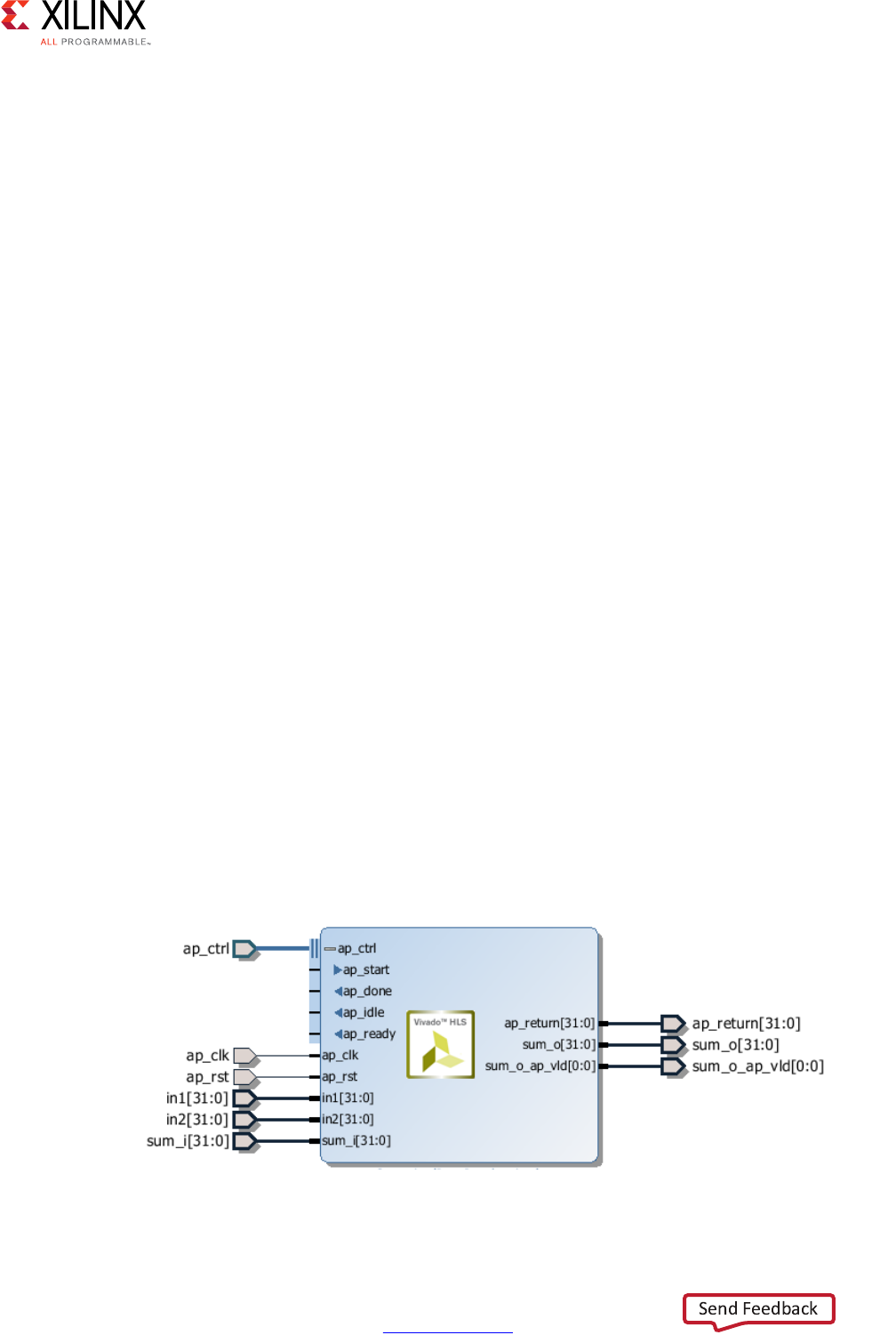
High-Level Synthesis 85
UG902 (v2017.1) April 5, 2017 www.xilinx.com
Chapter 1: High-Level Synthesis
°This solution is provided through SystemC designs, where the I/O control signals
are specified in the interface declaration and their behavior specified in the code.
°Vivado HLS also supports this mode of interface specification for C and C++
designs.
Interface Synthesis
When the top-level function is synthesized, the arguments (or parameters) to the function
are synthesized into RTL ports. This process is called interface synthesis.
Interface Synthesis Overview
The following code provides a comprehensive overview of interface synthesis.
#include "sum_io.h"
dout_t sum_io(din_t in1, din_t in2, dio_t *sum) {
dout_t temp;
*sum = in1 + in2 + *sum;
temp = in1 + in2;
return temp;
}
This example above includes:
• Two pass-by-value inputs in1 and in2.
•A pointer sum that is both read from and written to.
•A function return, the value of temp.
With the default interface synthesis settings, the design is synthesized into an RTL block
with the ports shown in the following figure.
X-Ref Target - Figure 1-37
Figure 1-37: RTL Ports After Default Interface Synthesis

High-Level Synthesis 86
UG902 (v2017.1) April 5, 2017 www.xilinx.com
Chapter 1: High-Level Synthesis
Vivado HLS creates three types of ports on the RTL design:
•Clock and Reset ports: ap_clk and ap_rst.
• Block-Level interface protocol. These are shown expanded in the preceding figure:
ap_start, ap_done, ap_ready, and ap_idle.
• Port Level interface protocols. These are created for each argument in the top-level
function and the function return (if the function returns a value). In this example, these
ports are: in1, in2, sum_i, sum_o, sum_o_ap_vld, and ap_return.
Clock and Reset Ports
If the design takes more than 1 cycle to complete operation.
A chip-enable port can optionally be added to the entire block using Solution > Solution
Settings > General and config_interface configuration.
The operation of the reset is controlled by the config_rtl configuration. More details on the
reset configuration are provided in Clock, Reset, and RTL Output.
Block-Level Interface Protocol
By default, a block-level interface protocol is added to the design. These signal control the
block, independently of any port-level I/O protocols. These ports control when the block
can start processing data (ap_start), indicate when it is ready to accept new inputs
(ap_ready) and indicate if the design is idle (ap_idle) or has completed operation
(ap_done).
Port-Level Interface Protocol
The final group of signals are the data ports. The I/O protocol created depends on the type
of C argument and on the default. A complete list of all possible I/O protocols is shown in
Figure 1-39. After the block-level protocol has been used to start the operation of the
block, the port-level IO protocols are used to sequence data into and out of the block.
By default input pass-by-value arguments and pointers are implemented as simple wire
ports with no associated handshaking signal. In the above example, the input ports are
therefore implemented without an I/O protocol, only a data port. If the port has no I/O
protocol, (by default or by design) the input data must be held stable until it is read.
By default output pointers are implemented with an associated output valid signal to
indicate when the output data is valid. In the above example, the output port is
implemented with an associated output valid port (sum_o_ap_vld) which indicates when the
data on the port is valid and can be read. If there is no I/O protocol associated with the
output port, it is difficult to know when to read the data. It is always a good idea to use an
I/O protocol on an output.
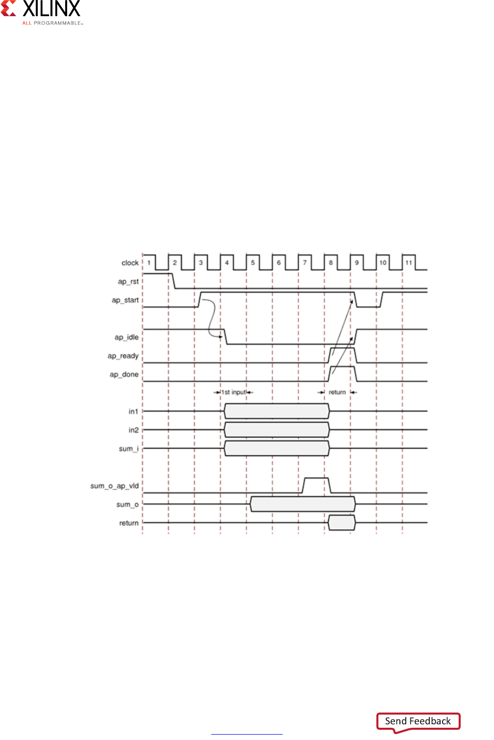
High-Level Synthesis 87
UG902 (v2017.1) April 5, 2017 www.xilinx.com
Chapter 1: High-Level Synthesis
Function arguments which are both read from and writes to are split into separate input and
output ports. In the above example, sum is implemented as input port sum_i and output
port sum_o with associated I/O protocol port sum_o_ap_vld.
If the function has a return value, an output port ap_return is implemented to provide the
return value. When the design completes one transaction - this is equivalent to one
execution of the C function - the block-level protocols indicate the function is complete
with the ap_done signal. This also indicates the data on port ap_return is valid and can
be read.
Note: The return value to the top-level function cannot be a pointer.
For the example code shown the timing behavior is shown in the following figure (assuming
that the target technology and clock frequency allow a single addition per clock cycle).
X-Ref Target - Figure 1-38
Figure 1-38: RTL Port Timing with Default Synthesis

High-Level Synthesis 88
UG902 (v2017.1) April 5, 2017 www.xilinx.com
Chapter 1: High-Level Synthesis
•The design starts when ap_start is asserted High.
•The ap_idle signal is asserted Low to indicate the design is operating.
• The input data is read at any clock after the first cycle. Vivado HLS schedules when the
reads occur. The ap_ready signal is asserted high when all inputs have been read.
• When output sum is calculated, the associated output handshake (sum_o_ap_vld)
indicates that the data is valid.
• When the function completes, ap_done is asserted. This also indicates that the data on
ap_return is valid.
•Port ap_idle is asserted High to indicate that the design is waiting start again.
Interface Synthesis and OpenCL API C
During synthesis, Vivado HLS groups all interfaces in OpenCL API C as follows:
• All scalar interfaces and the block-level interface into a single AXI4-Lite interface
• All arrays and pointers into a single AXI4 interface
Note: No other interface specifications are allowed for OpenCL API C kernels.
Interface Synthesis I/O Protocols
The type of interfaces that are created by interface synthesis depend on the type of C
argument, the default interface mode, and the INTERFACE optimization directive. The
following figure shows the interface protocol mode you can specify on each type of C
argument. This figure uses the following abbreviations:
•D: Default interface mode for each type.
Note: If you specify an illegal interface, Vivado HLS issues a message and implements the
default interface mode.
•I: Input arguments, which are only read.
•O: Output arguments, which are only written to.
•I/O: Input/Output arguments, which are both read and written.
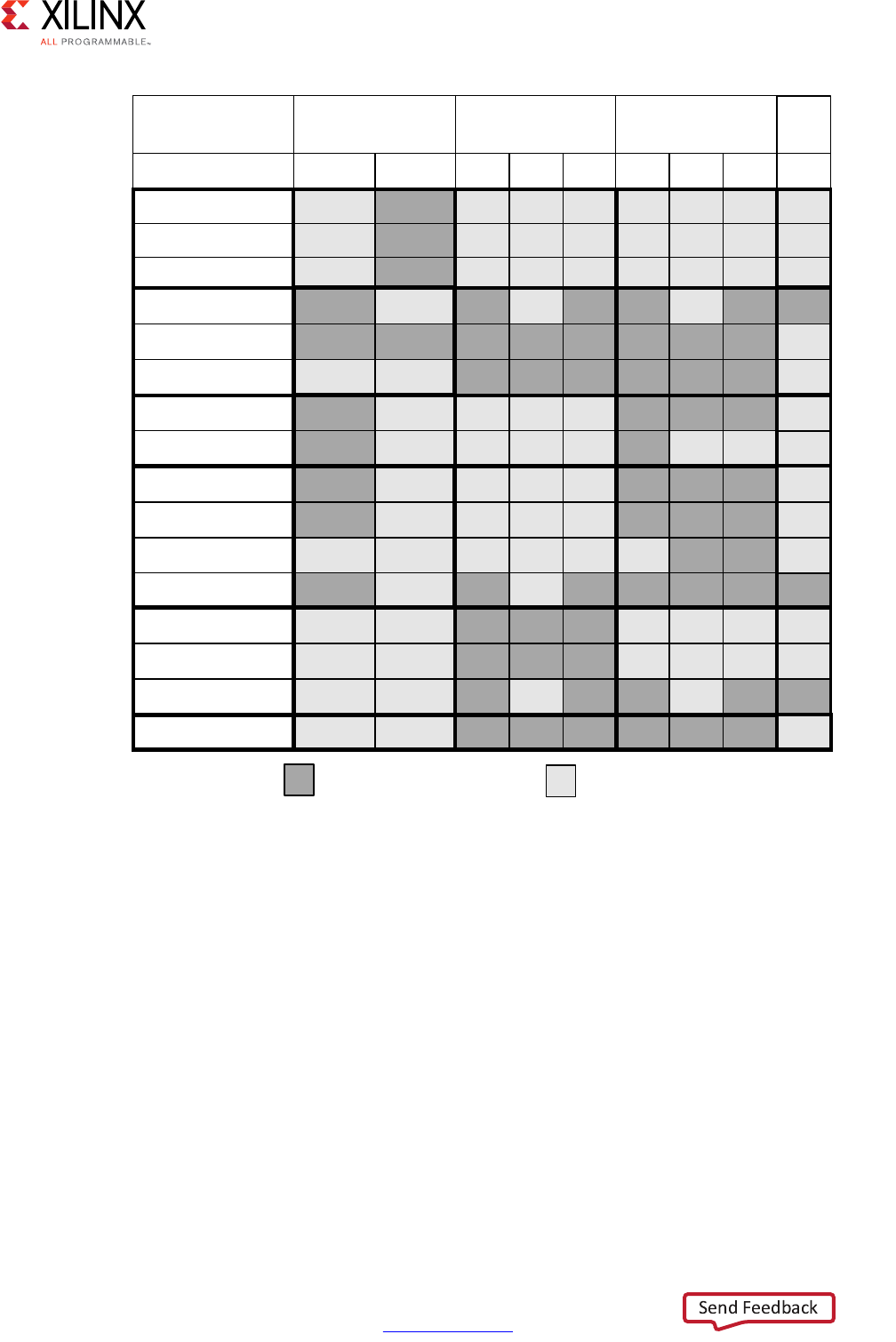
High-Level Synthesis 89
UG902 (v2017.1) April 5, 2017 www.xilinx.com
Chapter 1: High-Level Synthesis
Full details on the interfaces protocols, including waveform diagrams, are include in
Interface Synthesis Reference in Chapter 4. The following provides an overview of each
interface mode.
Block-Level Interface Protocols
The block-level interface protocols are ap_ctrl_none, ap_ctrl_hs, and
ap_ctrl_chain. These are specified, and can only be specified, on the function or the
function return. When the directive is specified in the GUI it will apply these protocols to the
function return. Even if the function does not use a return value, the block-level protocol
may be specified on the function return.
X-Ref Target - Figure 1-39
Figure 1-39: Data Type and Interface Synthesis Support
D
D
Input Return
Scalar
I I/O O
Array
D
D
D
I I/O O
Pointer or Reference
ap_ctrl_chain
axis
s_axilite
m_axi
ap_none
ap_stable
ap_ack
ap_vld
ap_ovld
ap_ctrl_hs
ap_ctrl_none
Interface Mode
Argument
Type
Supported D = Default Interface Not Supported
ap_hs
D D Dap_memory
bram
ap_fifo
ap_bus
;
I and O
D
HLS::
Stream

High-Level Synthesis 90
UG902 (v2017.1) April 5, 2017 www.xilinx.com
Chapter 1: High-Level Synthesis
The ap_ctrl_hs mode described in the previous example is the default protocol. The
ap_ctrl_chain protocol is similar to ap_ctrl_hs but has an additional input port
ap_continue which provides back pressure from blocks consuming the data from this
block. If the ap_continue port is logic 0 when the function completes, the block will halt
operation and the next transaction will not proceed. The next transaction will only proceed
when the ap_continue is asserted to logic 1.
The ap_ctrl_none mode implements the design without any block-level I/O protocol.
If the function return is also specified as an AXI4-Lite interface (s_axilite) all the ports in
the block-level interface are grouped into the AXI4-Lite interface. This is a common practice
when another device, such as a CPU, is used to configure and control when this block starts
and stops operation.
Port-Level Interface Protocols: AXI4 Interfaces
The AXI4 interfaces supported by Vivado HLS include the AXI4-Stream (axis), AXI4-Lite
(s_axilite), and AXI4 master (m_axi) interfaces, which you can specify as follows:
• AXI4-Stream interface: Specify on input arguments or output arguments only, not on
input/output arguments.
• AXI4-Lite interface: Specify on any type of argument except arrays. You can group
multiple arguments into the same AXI4-Lite interface.
• AXI4 master interface: Specify on arrays and pointers (and references in C++) only. You
can group multiple arguments into the same AXI4 interface.
For information on additional functionality provided by the AXI4 interface, see Using AXI4
Interfaces.
Port-Level Interface Protocols: No I/O Protocol
The ap_none and ap_stable modes specify that no I/O protocol be added to the port.
When these modes are specified the argument is implemented as a data port with no other
associated signals. The ap_none mode is the default for scalar inputs. The ap_stable
mode is intended for configuration inputs which only change when the device is in reset
mode.
Port-Level Interface Protocols: Wire Handshakes
Interface mode ap_hs includes a two-way handshake signal with the data port. The
handshake is an industry standard valid and acknowledge handshake. Mode ap_vld is the
same but only has a valid port and ap_ack only has a acknowledge port.

High-Level Synthesis 91
UG902 (v2017.1) April 5, 2017 www.xilinx.com
Chapter 1: High-Level Synthesis
Mode ap_ovld is for use with in-out arguments. When the in-out is split into separate
input and output ports, mode ap_none is applied to the input port and ap_vld applied to
the output port. This is the default for pointer arguments which are both read and written.
The ap_hs mode can be applied to arrays which are read or written in sequential order. If
Vivado HLS can determine the read or write accesses are not sequential it will halt synthesis
with an error. If the access order cannot be determined Vivado HLS will issue a warning.
Port-Level Interface Protocols: Memory Interfaces
Array arguments are implemented by default as an ap_memory interface. This is a standard
block RAM interface with data, address, chip-enable and write-enable ports.
An ap_memory interface may be implemented as a single-port of dual-port interface. If
Vivado HLS can determine that a using a dual-port interface will reduce the initial interval
it will automatically implement a dual-port interface. The RESOURE directive is used to
specify the memory resource and if this directive is specified on the array with a single-port
block RAM, a single-port interface will be implemented. Conversely, if a dual-port interface
is specified using the RESOURCE directive and Vivado HLS determines this interface
provides no benefit it will automatically implement a single-port interface.
The bram interface mode is functional identical to the ap_memory interface. The only
difference is how the ports are implemented when the design is used in Vivado IP
Integrator:
•An ap_memory interface is displayed as multiple and separate ports.
•A bram interface is displayed as a single grouped port which can be connected to a
Xilinx block RAM using a single point-to-point connection.
If the array is accessed in a sequential manner an ap_fifo interface can be used. As with
the ap_hs interface, Vivado HLS will halt if determines the data access is not sequential,
report a warning if it cannot determine if the access is sequential or issue no message if it
determines the access is sequential. The ap_fifo interface can only be used for reading or
writing, not both.
The ap_bus interface can communicate with a bus bridge. The interface does not adhere to
any specific bus standard but is generic enough to be used with a bus bridge that in-turn
arbitrates with the system bus. The bus bridge must be able to cache all burst writes.
Interface Synthesis and Structs
Structs on the interface are by default de-composed into their member elements and ports
are implemented separately for each member element. Each member element of the struct
will be implemented, in the absence of any INTERFACE directive, as shown in Figure 1-39.
Arrays of structs are implemented as multiple arrays, with a separate array for each member
of the struct.

High-Level Synthesis 92
UG902 (v2017.1) April 5, 2017 www.xilinx.com
Chapter 1: High-Level Synthesis
The DATA_PACK optimization directive is used for packing all the elements of a struct into a
single wide vector. This allows all members of the struct to be read and written to
simultaneously. The member elements of the struct are placed into the vector in the order
the appear in the C code: the first element of the struct is aligned on the LSB of the vector
and the final element of the struct is aligned with the MSB of the vector. Any arrays in the
struct are partitioned into individual array elements and placed in the vector from lowest to
highest, in order.
Care should be taken when using the DATA_PACK optimization on structs with large arrays.
If an array has 4096 elements of type int, this will result in a vector (and port) of width
4096*32=131072 bits. Vivado HLS can create this RTL design, however it is very unlikely
logic synthesis will be able to route this during the FPGA implementation.
The single wide-vector created by using the DATA_PACK directive allows more data to be
accessed in a single clock cycle. This is the case when the struct contains an array. When
data can be accessed in a single clock cycle, Vivado HLS automatically unrolls any loops
consuming this data, if doing so improves the throughput. The loop can be fully or partially
unrolled to create enough hardware to consume the additional data in a single clock cycle.
This feature is controlled using the config_unroll command and the option
tripcount_threshold. In the following example, any loops with a tripcount of less than
16 will be automatically unrolled if doing so improves the throughput.
config_unroll -tripcount_threshold 16
If a struct port using DATA_PACK is to be implemented with an AXI4 interface you may wish
to consider using the DATA_PACK byte_pad option. The byte_pad option is used to
automatically align the member elements to 8-bit boundaries. This alignment is sometimes
required by Xilinx IP. If an AXI4 port using DATA_PACK is to be implemented, refer to the
documentation for the Xilinx IP it will connect to and determine if byte alignment is
required.
For the following example code, the options for implementing a struct port are shown in
the following figure.
typedef struct{
int12 A;
int18 B[4];
int6 C;
} my_data;
void foo(my_data *a )
• By default, the members are implemented as individual ports. The array has multiple
ports (data, addr, etc.)
• Using DATA_PACK results in a single wide port.
•Using DATA_PACK with struct_level byte padding aligns entire struct to the next
8-bit boundary.
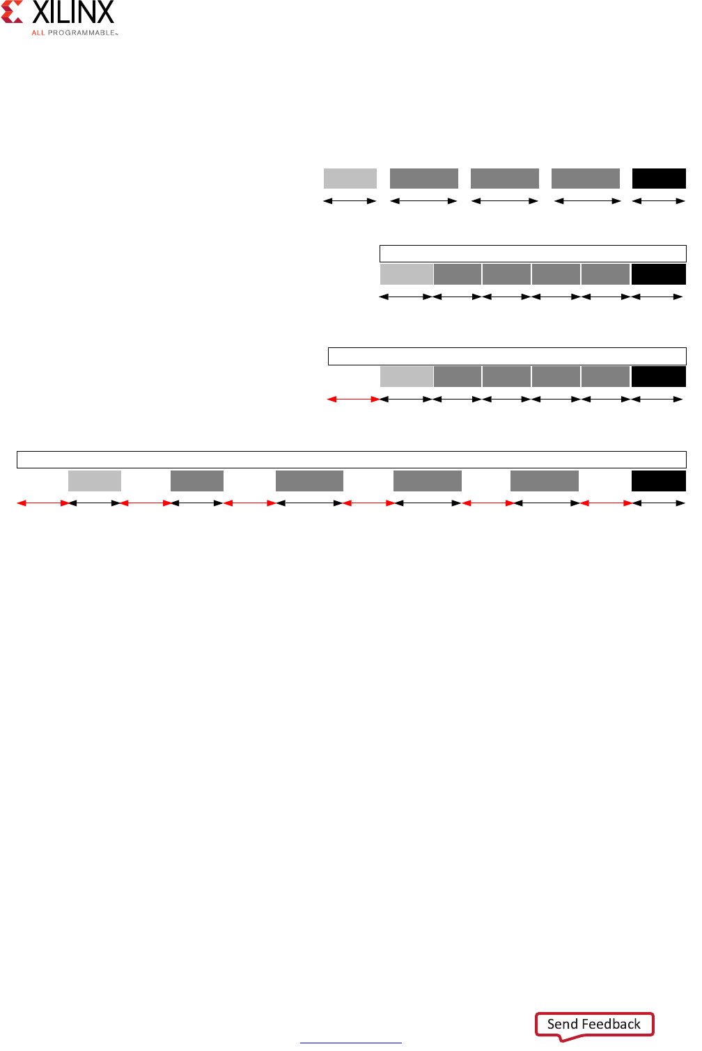
High-Level Synthesis 93
UG902 (v2017.1) April 5, 2017 www.xilinx.com
Chapter 1: High-Level Synthesis
•Using DATA_PACK with field_level byte padding aligns each struct member to the
next 8-bit boundary.
Note: The maximum bit-width of any port or bus created by data packing is 8192 bits.
If a struct contains arrays, those arrays can be optimized using the ARRAY_PARTITION
directive to partition the array or the ARRAY_RESHAPE directive to partition the array and
re-combine the partitioned elements into a wider array. The DATA_PACK directive performs
a similar operation as ARRAY_RESHAPE and combines the reshaped array with the other
elements in the struct.
A struct cannot be optimized with DATA_PACK and then partitioned or reshaped. The
DATA_PACK, ARRAY_PARTITION and ARRAY_RESHAPE directives are mutually exclusive.
X-Ref Target - Figure 1-40
Figure 1-40: DATA_PACK byte_pad Alignment Options
ELW
%BDGGU $%BFH %BGDWD&
6WUXFW3RUW,PSOHPHQWDWLRQ
ELW ELW ELW ELW
ELW
%>@ $&
'$7$B3$&.RSWLPL]DWLRQ
ELW
$
6LQJOHSDFNHGYHFWRU>@
'$7$B3$&.RSWLPL]DWLRQZLWKE\WHBSDGRQWKHVWUXFWBOHYHO
$
6LQJOHSDFNHGYHFWRUSRUW>@
'$7$B3$&.RSWLPL]DWLRQZLWKE\WHBSDGRQWKHILHOGBOHYHO
ELW
%>@ $%>@ %>@%>@
ELW ELW ELW ELW
$
6LQJOHSDFNHGYHFWRUSRUW>@
ELW
ELW
ELW
ELW
ELW
;
%>@ %>@ %>@
ELW ELW ELW ELW
ELW
%>@ $&
ELW
%>@ %>@ %>@
ELW ELW ELW ELW
ELW
ELW
&
ELW

High-Level Synthesis 94
UG902 (v2017.1) April 5, 2017 www.xilinx.com
Chapter 1: High-Level Synthesis
Interface Synthesis and Multi-Access Pointers
Using pointers which are accessed multiple times can introduce unexpected behavior after
synthesis. In the following example pointer d_i is read four times and pointer d_o is
written to twice: the pointers perform multiple accesses.
#include "pointer_stream_bad.h"
void pointer_stream_bad ( dout_t *d_o, din_t *d_i) {
din_t acc = 0;
acc += *d_i;
acc += *d_i;
*d_o = acc;
acc += *d_i;
acc += *d_i;
*d_o = acc;
}
After synthesis this code will result in an RTL design which reads the input port once and
writes to the output port once. As with any standard C compiler, Vivado HLS will optimize
away the redundant pointer accesses. To implement the above code with the “anticipated”
4 reads on d_i and 2 writes to the d_o the pointers must be specified as volatile as
shown in the next example.
#include "pointer_stream_better.h"
void pointer_stream_better ( volatile dout_t *d_o, volatile din_t *d_i) {
din_t acc = 0;
acc += *d_i;
acc += *d_i;
*d_o = acc;
acc += *d_i;
acc += *d_i;
*d_o = acc;
}
Even this C code is problematic. Using a test bench, there is no way to supply anything but
a single value to d_i or verify any write to d_o other than the final write. Although
multi-access pointers are supported, it is highly recommended to implement the behavior
required using the hls::stream class. Details on the hls::stream class are in HLS
Stream Library in Chapter 2.
Specifying Interfaces
Interface synthesis is controlled by the INTERFACE directive or by using a configuration
setting. To specify the interface mode on ports, select the port in the GUI Directives tab and
right-click the mouse to open the Vivado HLS Directive Editor as shown in the following
figure.
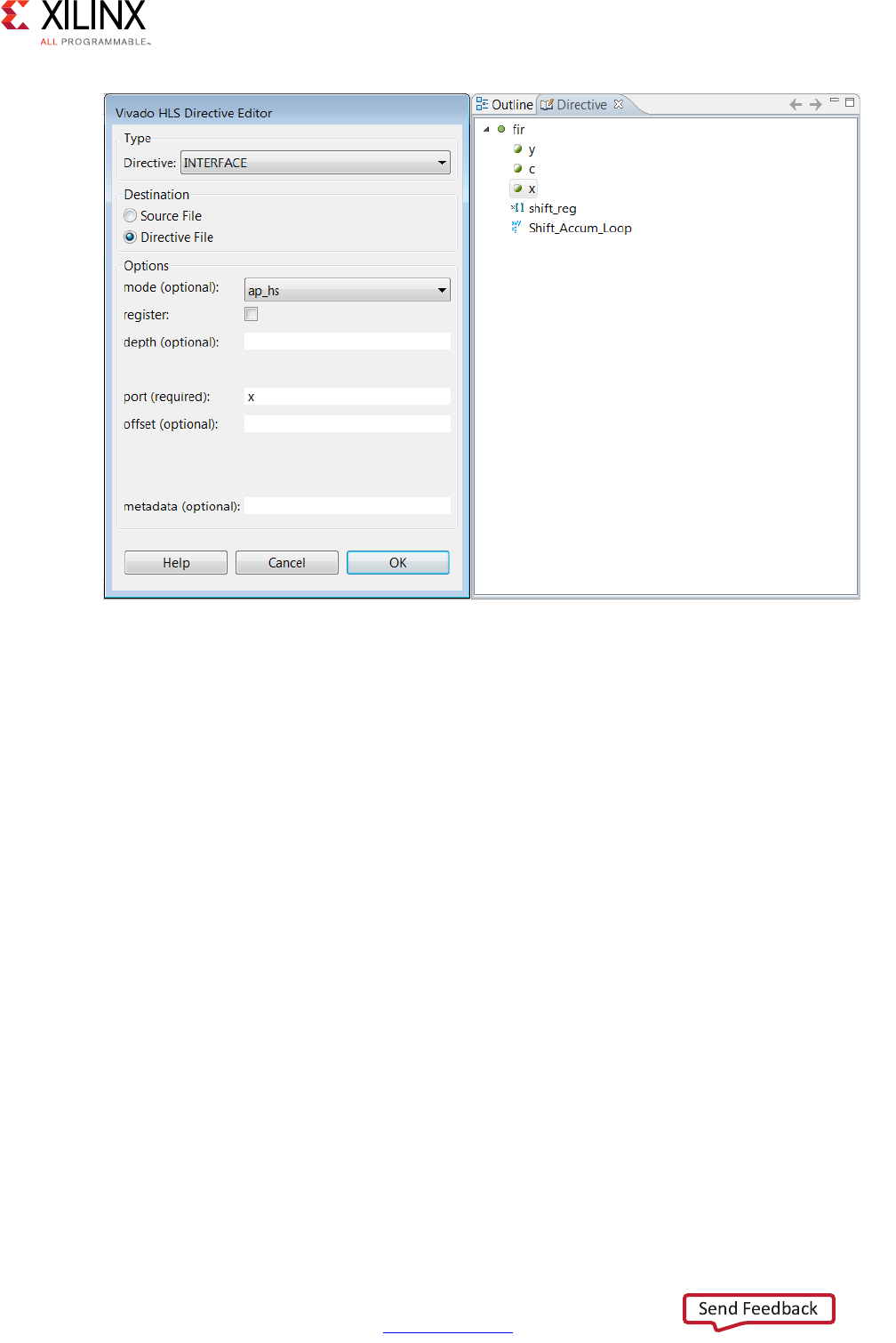
High-Level Synthesis 95
UG902 (v2017.1) April 5, 2017 www.xilinx.com
Chapter 1: High-Level Synthesis
In the Vivado HLS Directives Editor, set the following options:
•mode
Select the interface mode from the drop-down menu.
• register
If you select this option, all pass-by-value reads are performed in the first cycle of
operation. For output ports, the register option guarantees the output is registered. You
can apply the register option to any function in the design. For memory, FIFO, and AXI4
interfaces, the register option has no effect.
•depth
This option specifies how many samples are provided to the design by the test bench
and how many output values the test bench must store. Use whichever number is
greater.
Note: For cases in which a pointer is read from or written to multiple times within a single
transaction, the depth option is required for C/RTL co-simulation. The depth option is not
required for arrays or when using the hls::stream construct. It is only required when using
pointers on the interface.
X-Ref Target - Figure 1-41
Figure 1-41: Specifying Port Interfaces

High-Level Synthesis 96
UG902 (v2017.1) April 5, 2017 www.xilinx.com
Chapter 1: High-Level Synthesis
If the depth option is set too small, the C/RTL co-simulation might deadlock as follows:
°The input reads might stall waiting for data that the test bench cannot provide.
°The output writes might stall when trying to write data, because the storage is full.
•port
This option is required. By default, Vivado HLS does not register ports.
Note: To specify a block-level I/O protocol, select the top-level function in the Vivado HLS GUI,
and specify the port as the function return.
•offset
This option is used for AXI4 interfaces. For information, see Using AXI4 Interfaces.
To set the interface configuration, select Solution > Solution Settings > General >
config_interface. You can use configuration settings to:
• Add a global clock enable to the RTL design.
• Remove dangling ports, such as those created by elements of a struct that are not used
in the design.
• Create RTL ports for any global variables.
Any C function can use global variables: those variables defined outside the scope of any
function. By default, global variables do not result in the creation of RTL ports: Vivado HLS
assumes the global variable is inside the final design. The config_interface
configuration setting expose_global instructs Vivado HLS to create a ports for global
variables. For more information on the synthesis of global variables, see Global Variables in
Chapter 3.
Interface Synthesis for SystemC
In general, interface synthesis is not supported for SystemC designs. The I/O ports for
SystemC designs are fully specified in the SC_MODULE interface and the behavior of the
ports fully described in the source code. Interface synthesis is provided to support:
•Memory block RAM interfaces
• AXI4-Stream interfaces
• AXI4-Lite interfaces
• AXI4 master interfaces

High-Level Synthesis 97
UG902 (v2017.1) April 5, 2017 www.xilinx.com
Chapter 1: High-Level Synthesis
The processes for performing interface synthesis on a SystemC design is different from
adding the same interfaces to C or C++ designs.
• Memory block RAM and AXI4 master interfaces require the SystemC data port is
replaced with a Vivado HLS port.
• AXI4-Stream and AXI4-Lite slave interfaces only require directives but there is a
different process for adding directives to a SystemC design.
Applying Interface Directives with SystemC
When adding directives as pragmas to SystemC source code, the pragma directives cannot
be added where the ports are specified in the SC_MODULE declaration, they must be added
inside a function called by the SC_MODULE.
When adding directives using the GUI:
• Open the C source code and directives tab.
• Select the function which requires a directive.
• Right-click with the mouse and the INTERFACE directive to the function.
The directives can be applied to any member function of the SC_MODULE, however it is a
good design practice to add them to the function where the variables are used.
Block RAM Memory Ports
Given a SystemC design with an array port on the interface:
SC_MODULE(my_design) {
//”RAM” Port
sc_uint<20> my_array[256];
…
The port my_array is synthesized into an internal block RAM, not a block RAM interface
port.
Including the Vivado HLS header file ap_mem_if.h allows the same port to be specified as
an ap_mem_port<data_width, address_bits> port. The ap_mem_port data type is
synthesized into a standard block RAM interface with the specified data and address
bus-widths and using the ap_memory port protocol.
#include "ap_mem_if.h"
SC_MODULE(my_design) {
//”RAM” Port
ap_mem_port<sc_uint<20>,sc_uint<8>, 256> my_array;
…

High-Level Synthesis 98
UG902 (v2017.1) April 5, 2017 www.xilinx.com
Chapter 1: High-Level Synthesis
When an ap_mem_port is added to a SystemC design, an associated ap_mem_chn must be
added to the SystemC test bench to drive the ap_mem_port. In the test bench, an
ap_mem_chn is defined and attached to the instance as shown:
#include "ap_mem_if.h"
ap_mem_chn<int,int, 68> bus_mem;
…
// Instantiate the top-level module
my_design U_dut (“U_dut”)
U_dut.my_array.bind(bus_mem);
…
The header file ap_mem_if.h is located in the include directory located in the Vivado HLS
installation area and must be included if simulation is performed outside Vivado HLS.
SystemC AXI4-Stream Interface
An AXI4-Stream interface can be added to any SystemC ports that are of the sc_fifo_in
or sc_fifo_out type. The following shows the top-level of a typical SystemC design. As is
typical, the SC_MODULE and ports are defined in a header file:
SC_MODULE(sc_FIFO_port)
{
//Ports
sc_in <bool> clock;
sc_in <bool> reset;
sc_in <bool> start;
sc_out<bool> done;
sc_fifo_out<int> dout;
sc_fifo_in<int> din;
//Variables
int share_mem[100];
bool write_done;
//Process Declaration
void Prc1();
void Prc2();
//Constructor
SC_CTOR(sc_FIFO_port)
{
//Process Registration
SC_CTHREAD(Prc1,clock.pos());
reset_signal_is(reset,true);
SC_CTHREAD(Prc2,clock.pos());
reset_signal_is(reset,true);
}
};

High-Level Synthesis 99
UG902 (v2017.1) April 5, 2017 www.xilinx.com
Chapter 1: High-Level Synthesis
To create an AXI4-Stream interface the RESOURCE directive must be used to specify the
ports are connected an AXI4-Stream resource. For the example interface shown above, the
directives are shown added in the function called by the SC_MODULE: ports din and dout
are specified to have an AXI4-Stream resource.
#include "sc_FIFO_port.h"
void sc_FIFO_port::Prc1()
{
//Initialization
write_done = false;
wait();
while(true)
{
while (!start.read()) wait();
write_done = false;
for(int i=0;i<100; i++)
share_mem[i] = i;
write_done = true;
wait();
} //end of while(true)
}
void sc_FIFO_port::Prc2()
{
#pragma HLS resource core=AXI4Stream variable=din
#pragma HLS resource core=AXI4Stream variable=dout
//Initialization
done = false;
wait();
while(true)
{
while (!start.read()) wait();
wait();
while (!write_done) wait();
for(int i=0;i<100; i++)
{
dout.write(share_mem[i]+din.read());
}
done = true;
wait();
} //end of while(true)
}
When the SystemC design is synthesized, it results in an RTL design with standard RTL FIFO
ports. When the design is packaged as IP using the Export RTL toolbar button , the
output is a design with an AXI4-Stream interfaces.

High-Level Synthesis 100
UG902 (v2017.1) April 5, 2017 www.xilinx.com
Chapter 1: High-Level Synthesis
SystemC AXI4-Lite Interface
An AXI4-Lite slave interface can be added to any SystemC ports of type sc_in or sc_out.
The following example shows the top-level of a typical SystemC design. In this case, as is
typical, the SC_MODULE and ports are defined in a header file:
SC_MODULE(sc_sequ_cthread){
//Ports
sc_in <bool> clk;
sc_in <bool> reset;
sc_in <bool> start;
sc_in<sc_uint<16> > a;
sc_in<bool> en;
sc_out<sc_uint<16> > sum;
sc_out<bool> vld;
//Variables
sc_uint<16> acc;
//Process Declaration
void accum();
//Constructor
SC_CTOR(sc_sequ_cthread){
//Process Registration
SC_CTHREAD(accum,clk.pos());
reset_signal_is(reset,true);
}
};
To create an AXI4-Lite interface the RESOURCE directive must be used to specify the ports
are connected to an AXI4-Lite resource. For the example interface shown above, the
following example shows how ports start, a, en, sum and vld are grouped into the same
AXI4-Lite interface slv0: all the ports are specified with the same bus_bundle name and
are grouped into the same AXI4-Lite interface.

High-Level Synthesis 101
UG902 (v2017.1) April 5, 2017 www.xilinx.com
Chapter 1: High-Level Synthesis
#include "sc_sequ_cthread.h"
void sc_sequ_cthread::accum(){
//Group ports into AXI4 slave slv0
#pragma HLS resource core=AXI4LiteS metadata="-bus_bundle slv0" variable=start
#pragma HLS resource core=AXI4LiteS metadata="-bus_bundle slv0" variable=a
#pragma HLS resource core=AXI4LiteS metadata="-bus_bundle slv0" variable=en
#pragma HLS resource core=AXI4LiteS metadata="-bus_bundle slv0" variable=sum
#pragma HLS resource core=AXI4LiteS metadata="-bus_bundle slv0" variable=vld
//Initialization
acc=0;
sum.write(0);
vld.write(false);
wait();
// Process the data
while(true) {
// Wait for start
wait();
while (!start.read()) wait();
// Read if valid input available
if (en) {
acc = acc + a.read();
sum.write(acc);
vld.write(true);
} else {
vld.write(false);
}
}
}
When the SystemC design is synthesized, it results in an RTL design with standard RTL ports.
When the design is packaged as IP using Export RTL toolbar button , the output is a
design with an AXI4-Lite interface.
SystemC AXI4 Master Interface
In most standard SystemC designs, you have no need to specify a port with the behavior of
the Vivado HLS ap_bus I/O protocol. However, if the design requires an AXI4 master bus
interface the ap_bus I/O protocol is required.

High-Level Synthesis 102
UG902 (v2017.1) April 5, 2017 www.xilinx.com
Chapter 1: High-Level Synthesis
To specify an AXI4 master interface on a SystemC design:
• Use the Vivado HLS type AXI4M_bus_port to create an interface with the ap_bus I/O
protocol.
• Assign an AXI4M resource to the port.
The following example shows how an AXI4M_bus_port called bus_if is added to a
SystemC design.
• The header file AXI4_if.h must be added to the design.
• The port is defined as AXI4M_bus_port<type>, where type specifies the data type to
be used (in this example, an sc_fixed type is used).
Note: The data type used in the AXI4M_bus_port must be multiples of 8-bit. In addition, structs
are not supported for this data type.
#include "systemc.h"
#include "AXI4_if.h"
#include "tlm.h"
using namespace tlm;
#define DT sc_fixed<32, 8>
SC_MODULE(dut)
{
//Ports
sc_in<bool> clock; //clock input
sc_in<bool> reset;
sc_in<bool> start;
sc_out<int> dout;
AXI4M_bus_port<sc_fixed<32, 8> > bus_if;
//Variables
//Constructor
SC_CTOR(dut)
//:bus_if ("bus_if")
{
//Process Registration
SC_CTHREAD(P1,clock.pos());
reset_signal_is(reset,true);
}
}

High-Level Synthesis 103
UG902 (v2017.1) April 5, 2017 www.xilinx.com
Chapter 1: High-Level Synthesis
The following shows how the variable bus_if can be accessed in the SystemC function to
produce standard or burst read and write operations.
//Process Declaration
void P1() {
//Initialization
dout.write(10);
int addr = 10;
DT tmp[10];
wait();
while(1) {
tmp[0]=10;
tmp[1]=11;
tmp[2]=12;
while (!start.read()) wait();
// Port read
tmp[0] = bus_if->read(addr);
// Port burst read
bus_if->burst_read(addr,2,tmp);
// Port write
bus_if->write(addr, tmp);
// Port burst write
bus_if->burst_write(addr,2,tmp);
dout.write(tmp[0].to_int());
addr+=2;
wait();
}
}
When the port class AXI4M_bus_port is used in a design, it must have a matching HLS bus
interface channel hls_bus_chn<start_addr > in the test bench, as shown in the
following example:
#include <systemc.h>
#include "tlm.h"
using namespace tlm;
#include "hls_bus_if.h"
#include "AE_clock.h"
#include "driver.h"
#ifdef __RTL_SIMULATION__
#include "dut_rtl_wrapper.h"
#define dut dut_rtl_wrapper
#else
#include "dut.h"
#endif
int sc_main (int argc , char *argv[])
{
sc_report_handler::set_actions("/IEEE_Std_1666/deprecated", SC_DO_NOTHING);
sc_report_handler::set_actions( SC_ID_LOGIC_X_TO_BOOL_, SC_LOG);

High-Level Synthesis 104
UG902 (v2017.1) April 5, 2017 www.xilinx.com
Chapter 1: High-Level Synthesis
sc_report_handler::set_actions( SC_ID_VECTOR_CONTAINS_LOGIC_VALUE_, SC_LOG);
sc_report_handler::set_actions( SC_ID_OBJECT_EXISTS_, SC_LOG);
// hls_bus_chan<type>
// bus_variable(“name”, start_addr, end_addr)
//
hls_bus_chn<sc_fixed<32, 8> > bus_mem("bus_mem",0,1024);
sc_signal<bool> s_clk;
sc_signal<bool> reset;
sc_signal<bool> start;
sc_signal<int> dout;
AE_Clock U_AE_Clock("U_AE_Clock", 10);
dut U_dut("U_dut");
driver U_driver("U_driver");
U_AE_Clock.reset(reset);
U_AE_Clock.clk(s_clk);
U_dut.clock(s_clk);
U_dut.reset(reset);
U_dut.start(start);
U_dut.dout(dout);
U_dut.bus_if(bus_mem);
U_driver.clk(s_clk);
U_driver.start(start);
U_driver.dout(dout);
int end_time = 8000;
cout << "INFO: Simulating " << endl;
// start simulation
sc_start(end_time, SC_NS);
return U_driver.ret;
};
The synthesized RTL design contains an interface with the ap_bus I/O protocol.
When the AXI4M_bus_port class is used, it results in an RTL design with an ap_bus
interface. When the design is packaged as IP using Export RTL the output is a design with an
AXI4 master port.
Specifying Manual Interface
You can use Vivado HLS to identify blocks of code that define a specific I/O protocol. This
allows you to specify an I/O protocol using a directive instead of using Interface Synthesis
or SystemC.
Note: You can also specify an I/O protocol with SystemC designs to provide greater I/O control.

High-Level Synthesis 105
UG902 (v2017.1) April 5, 2017 www.xilinx.com
Chapter 1: High-Level Synthesis
The following examples show the requirements and advantages of manual interface
specifications. In the first code example, the following occurs:
1. Input response[0] is read.
2. Output request is written.
3. Input response[1] is read.
void test (
int *z1,
int a,
int b,
int *mode,
volatile int *request,
volatile int response[2],
int *z2
) {
int read1, read2;
int opcode;
int i;
P1: {
read1 = response[0];
opcode = 5;
*request = opcode;
read2 = response[1];
}
C1: {
*z1 = a + b;
*z2 = read1 + read2;
}
}
When Vivado HLS implements this code, the write to request does not need to occur
between the two reads on response. The code uses this I/O behavior, but there are no
dependencies in the code enforce the I/O behavior. Vivado HLS might schedule the I/O
accesses using the same access pattern as the C code or use a different access pattern.
If there is an external requirement that the I/O accesses must occur in this order, you can
use a protocol block to enforce a specific I/O protocol behavior. Because the accesses occur
in the scope defined by block P1, you can apply an I/O protocol as follows:
1. Include the ap_utils.h header file that defines applet().
2. Place an ap_wait() statement after the write to request but before the read on
response[1].
Note: The ap_wait() statement does not alter the behavior of the C simulation. It instructs
Vivado HLS to insert a clock between the I/O accesses during synthesis.

High-Level Synthesis 106
UG902 (v2017.1) April 5, 2017 www.xilinx.com
Chapter 1: High-Level Synthesis
The modified code now contains the header file and ap_wait() statements:
#include "ap_utils.h" // Added include file
void test (
int *z1,
int a,
int b,
int *mode,
volatile int *request,
volatile int response[2],
int *z2
) {
int read1, read2;
int opcode;
int i;
P1: {
read1 = response[0];
opcode = 5;
ap_wait();// Added ap_wait statement
*request = opcode;
read2 = response[1];
}
C1: {
*z1 = a + b;
*z2 = read1 + read2;
}
}
3. Specify that block P1 is a protocol region using the PROTOCOL directive:
set_directive_protocol test P1 -mode floating
This instructs Vivado HLS to schedule the code within this region as is. There is no
reordering of the I/O or ap_wait() statements.
This results in the following exact I/O behavior specified in the code:
1. Input response[0] is read.
2. Output request is written.
3. Input response[1] is read.
Note: If allowed by data dependencies, the -mode floating option allows other code to execute in
parallel with this block. The -fixed mode prevents this.

High-Level Synthesis 107
UG902 (v2017.1) April 5, 2017 www.xilinx.com
Chapter 1: High-Level Synthesis
Use the following guidelines when manually specifying I/O protocols:
• Do not use an I/O protocol on the ports used in a manual interface. Explicitly set all
ports to I/O protocol ap_none to ensure interface synthesis does not add any
additional protocol signals.
• You must specify all the control signals used in a manually specified interface in the C
code with volatile type qualifier. These signals typically change value multiple times
within the function (for example, typically set to 0, then 1, then back to zero). Without
the volatile qualifier, Vivado HLS follows standard C semantics and optimizes out all
intermediate operations, leaving only the first read and final write.
•Use the volatile qualifier to specify data signals with values that will be updated
multiples times.
• If multiple clocks are required, use ap_wait_n(<value>) to specify multiple cycles.
Do not use multiple ap_wait() statements.
• Group signals that need to change in the same clock cycle using the latency directive.
For example:
{
#pragma HLS PROTOCOL fixed
// A protocol block may span multiple clock cycles
// To ensure both these signals are scheduled in the exact same clock cycle.
// create a region { } with a latency = 0
{
#pragma HLS LATENCY max=0 min=0
*data = 0xFF;
*data_vld = 1;
}
ap_wait_n(2);
}
Using AXI4 Interfaces
AXI4-Stream Interfaces
An AXI4-Stream interface can be applied to any input argument and any array or pointer
output argument. Since an AXI4-Stream interface transfers data in a sequential streaming
manner it cannot be used with arguments which are both read and written. An AXI4-Stream
interface is always sign-extended to the next byte. For example, a 12-bit data value is
sign-extended to 16-bit.

High-Level Synthesis 108
UG902 (v2017.1) April 5, 2017 www.xilinx.com
Chapter 1: High-Level Synthesis
AXI4-Stream interfaces are always implemented as registered interfaces to ensure no
combinational feedback paths are created when multiple HLS IP blocks with AXI-Stream
interfaces are integrated into a larger design. For AXI-Stream interfaces, four types of
register modes are provided to control how the AXI-Stream interface registers are
implemented.
•Forward: Only the TDATA and TVALID signals are registered.
• Reverse: Only the TREADY signal is registered.
• Both: All signals (TDATA, TREADY and TVALID) are registered. This is the default.
• Off: None of the port signals are registered.
The AXI-Stream side-channel signals, discussed later in AXI4-Stream Interfaces with
Side-Channels, are considered to be data signals and are registered whenever TDATA is
registered.
RECOMMENDED: When connecting HLS generated IP blocks with AXI4-Stream interfaces at
least one interface should be implemented as a registered interface or the blocks should be
connected via an AXI4-Stream Register Slice.
There are two basic ways to use an AXI4-Stream in your design.
• Use an AXI4-Stream without side-channels.
• Use an AXI4-Stream with side-channels.
This second use model provides additional functionality, allowing the optional
side-channels which are part of the AXI4-Stream standard, to be used directly in the C code.
AXI4-Stream Interfaces without Side-Channels
An AXI4-Stream is used without side-channels when the function argument does not
contain any AXI4 side-channel elements. The following example shown a design where the
data type is a standard C int type. In this example, both interfaces are implemented using
an AXI4-Stream.
void example(int A[50], int B[50]) {
//Set the HLS native interface types
#pragma HLS INTERFACE axis port=A
#pragma HLS INTERFACE axis port=B
int i;
for(i = 0; i < 50; i++){
B[i] = A[i] + 5;
}
}
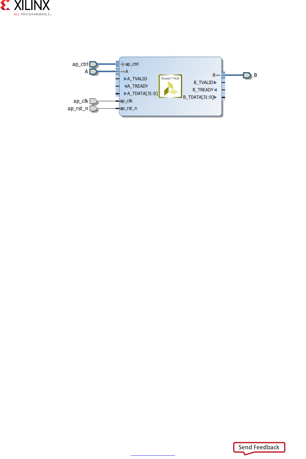
High-Level Synthesis 109
UG902 (v2017.1) April 5, 2017 www.xilinx.com
Chapter 1: High-Level Synthesis
After synthesis, both arguments are implemented with a data port and the standard
AXI4-Stream TVALID and TREADY protocol ports as shown in the following figure.
Multiple variables can be combined into the same AXI4-Stream interface by using a struct
and the DATA_PACK directive. If an argument to the top-level function is a struct, Vivado
HLS by default partitions the struct into separate elements and implements each member of
the struct as a separate port. However, the DATA_PACK directive may be used to pack the
elements of a struct into a single wide-vector, allowing all elements of the struct to be
implemented in the same AXI4-Stream interface. Complete details on packing structs and
using the byte padding option to align the data fields in the wide-vector are provided in
Interface Synthesis and Structs.
AXI4-Stream Interfaces with Side-Channels
Side-channels are optional signals which are part of the AXI4-Stream standard. The
side-channel signals may be directly referenced and controlled in the C code using a struct,
provided the member elements of the struct match the names of the AXI4-Stream
side-channel signals. The AXI-Stream side-channel signals are considered data signals and
are registered whenever TDATA is registered. An example of this is provided with Vivado
HLS. The Vivado HLS include directory contains the file ap_axi_sdata.h. This header
file contains the following structs:
X-Ref Target - Figure 1-42
Figure 1-42: AXI4-Stream Interfaces Without Side-Channels

High-Level Synthesis 110
UG902 (v2017.1) April 5, 2017 www.xilinx.com
Chapter 1: High-Level Synthesis
#include "ap_int.h"
template<int D,int U,int TI,int TD>
struct ap_axis{
ap_int<D> data;
ap_uint<D/8> keep;
ap_uint<D/8> strb;
ap_uint<U> user;
ap_uint<1> last;
ap_uint<TI> id;
ap_uint<TD> dest;
};
template<int D,int U,int TI,int TD>
struct ap_axiu{
ap_uint<D> data;
ap_uint<D/8> keep;
ap_uint<D/8> strb;
ap_uint<U> user;
ap_uint<1> last;
ap_uint<TI> id;
ap_uint<TD> dest;
};
Both structs contain as top-level members, variables whose names match those of the
optional AXI4-Stream side-channel signals. Provided the struct contains elements with
these names, there is no requirement to use the header file provided. You can create your
own user defined structs. Since the structs shown above use ap_int types and templates,
this header file is only for use in C++ designs.
Note: The valid and ready signals are mandatory signals in an AXI4-Stream and will always be
implemented by Vivado HLS. These cannot be controlled using a struct.
The following example shows how the side-channels can be used directly in the C code and
implemented on the interface. In this example a signed 32-bit data type is used.
#include "ap_axi_sdata.h"
void example(ap_axis<32,2,5,6> A[50], ap_axis<32,2,5,6> B[50]){
//Map ports to Vivado HLS interfaces
#pragma HLS INTERFACE axis port=A
#pragma HLS INTERFACE axis port=B
int i;
for(i = 0; i < 50; i++){
B[i].data = A[i].data.to_int() + 5;
B[i].keep = A[i].keep;
B[i].strb = A[i].strb;
B[i].user = A[i].user;
B[i].last = A[i].last;
B[i].id = A[i].id;
B[i].dest = A[i].dest;
}
}
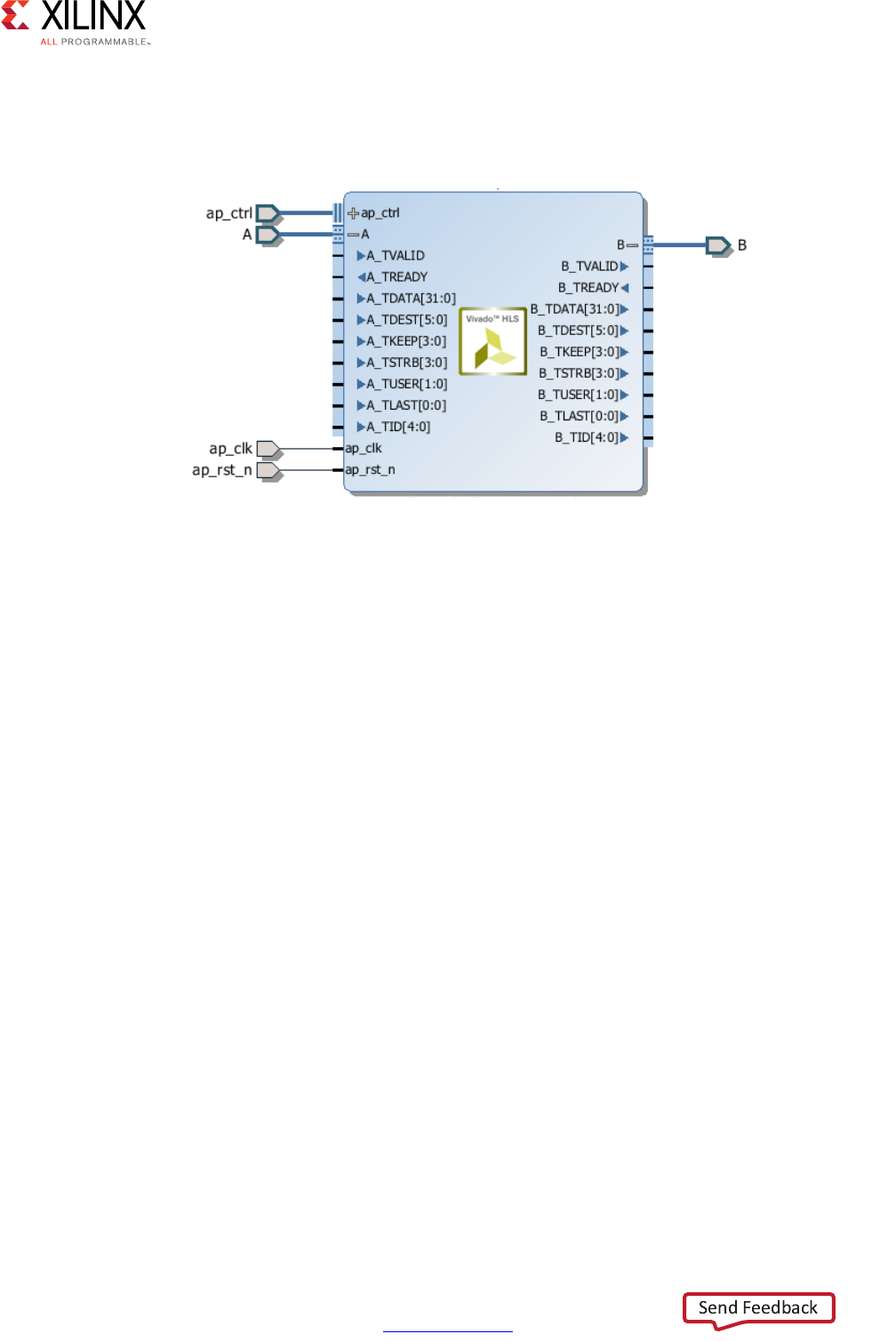
High-Level Synthesis 111
UG902 (v2017.1) April 5, 2017 www.xilinx.com
Chapter 1: High-Level Synthesis
After synthesis, both arguments are implemented with data ports, the standard
AXI4-Stream TVALID and TREADY protocol ports and all of the optional ports described in
the struct.
Packing Structs into AXI4-Stream Interfaces
There is a difference in the default synthesis behavior when using structs with AXI4-Stream
interfaces. The default synthesis behavior for struct is described in Interface Synthesis and
Structs in Chapter 1.
When using AXI4-Stream interfaces without side-channels and the function argument is a
struct:
• Vivado HLS automatically applies the DATA_PACK directive and all elements of the
struct are combined into a single wide-data vector. The interface is implemented as a
single wide-data vector with associated TVALID and TREADY signals.
•If the DATA_PACK directive is manually applied to the struct, all elements of the struct
are combined into a single wide-data vector and the AXI alignment options to the
DATA_PACK directive may be applied. The interface is implemented as a single
wide-data vector with associated TVALID and TREADY signals.
When using AXI4-Stream interfaces with side-channels, the function argument is itself a
struct (AXI-Stream struct). It can contain data which is itself a struct (data struct) along with
the side-channels:
• Vivado HLS automatically applies the DATA_PACK directive to the data struct and all
elements of the data struct are combined into a single wide-data vector. The interface is
implemented as a single wide-data vector with associated side-channels, TVALID and
TREADY signals.
X-Ref Target - Figure 1-43
Figure 1-43: AXI4-Stream Interfaces With Side-Channels

High-Level Synthesis 112
UG902 (v2017.1) April 5, 2017 www.xilinx.com
Chapter 1: High-Level Synthesis
•If the DATA_PACK directive is manually applied to the data struct, all elements of the
data struct are combined into a single wide-data vector and the AXI alignment options
to the DATA_PACK directive may be applied. The interface is implement as a single
wide-data vector with associated side-channels, TVALID and TREADY signals.
•If the DATA_PACK directive is applied to AXI-Stream struct, the function argument, the
data struct and the side-channel signals are combined into a single wide-vector. The
interface is implemented as a single wide-data vector with TVALID and TREADY
signals.
AXI4-Lite Interface
You can use an AXI4-Lite interface to allow the design to be controlled by a CPU or
microcontroller. Using the Vivado HLS AXI4-Lite interface, you can:
• Group multiple ports into the same AXI4-Lite interface.
• Output C driver files for use with the code running on a processor.
Note: This provides a set of C application program interface (API) functions, which allows you to
easily control the hardware from the software. This is useful when the design is exported to the
IP Catalog.
The following example shows how Vivado HLS implements multiple arguments, including
the function return, as an AXI4-Lite interface. Because each directive uses the same name
for the bundle option, each of the ports is grouped into the same AXI4-Lite interface.
void example(char *a, char *b, char *c)
{
#pragma HLS INTERFACE s_axilite port=return bundle=BUS_A
#pragma HLS INTERFACE s_axilite port=a bundle=BUS_A
#pragma HLS INTERFACE s_axilite port=b bundle=BUS_A
#pragma HLS INTERFACE s_axilite port=c bundle=BUS_A offset=0x0400
#pragma HLS INTERFACE ap_vld port=b
*c += *a + *b;
}
Note: If you do not use the bundle option, Vivado HLS groups all arguments specified with an
AXI4-Lite interface into the same default bundle and automatically names the port.
You can also assign an I/O protocol to ports grouped into an AXI4-Lite interface. In the
example above, Vivado HLS implements port b as an ap_vld interface and groups port b
into the AXI4-Lite interface. As a result, the AXI4-Lite interface contains a register for the
port b data, a register for the output to acknowledge that port b was read, and a register
for the port b input valid signal.
Each time port b is read, Vivado HLS automatically clears the input valid register and resets
the register to logic 0. If the input valid register is not set to logic 1, the data in the b data
register is not considered valid, and the design stalls and waits for the valid register to be
set.

High-Level Synthesis 113
UG902 (v2017.1) April 5, 2017 www.xilinx.com
Chapter 1: High-Level Synthesis
RECOMMENDED: For ease of use during the operation of the design, Xilinx recommends that you do not
include additional I/O protocols in the ports grouped into an AXI4-Lite interface. However, Xilinx
recommends that you include the block-level I/O protocol associated with the return port in the
AXI4-Lite interface.
You cannot assign arrays to an AXI4-Lite interface using the bram interface. You can only
assign arrays to an AXI4-Lite interface using the default ap_memory interface. You also
cannot assign any argument specified with ap_stable I/O protocol to an AXI4-Lite
interface.
Since the variables grouped into an AXI-Lite interface are function arguments, which
themselves cannot be assigned a default value in the C code, none of the registers in an
AXI-Lite interface may be assigned a default value. The registers can be implemented with
a reset with the config_rtl command, but they cannot be assigned any other default
value.
By default, Vivado HLS automatically assigns the address for each port that is grouped into
an AXI4-Lite interface. Vivado HLS provides the assigned addresses in the C driver files. For
more information, see C Driver Files. To explicitly define the address, you can use the
offset option, as shown for argument c in the example above.
IMPORTANT: In an AXI4-Lite interface, Vivado HLS reserves addresses 0x0000 through 0x000C for the
block-level I/O protocol signals and interrupt controls.
After synthesis, Vivado HLS implements the ports in the AXI4-Lite port, as shown in the
following figure. Vivado HLS creates the interrupt port by including the function return in
the AXI4-Lite interface. You can program the interrupt through the AXI4-Lite interface. You
can also drive the interrupt from the following block-level protocols:
•ap_done: Indicates when the function completes all operations.
•ap_ready: Indicates when the function is ready for new input data.
You can program the interface using the C driver files.
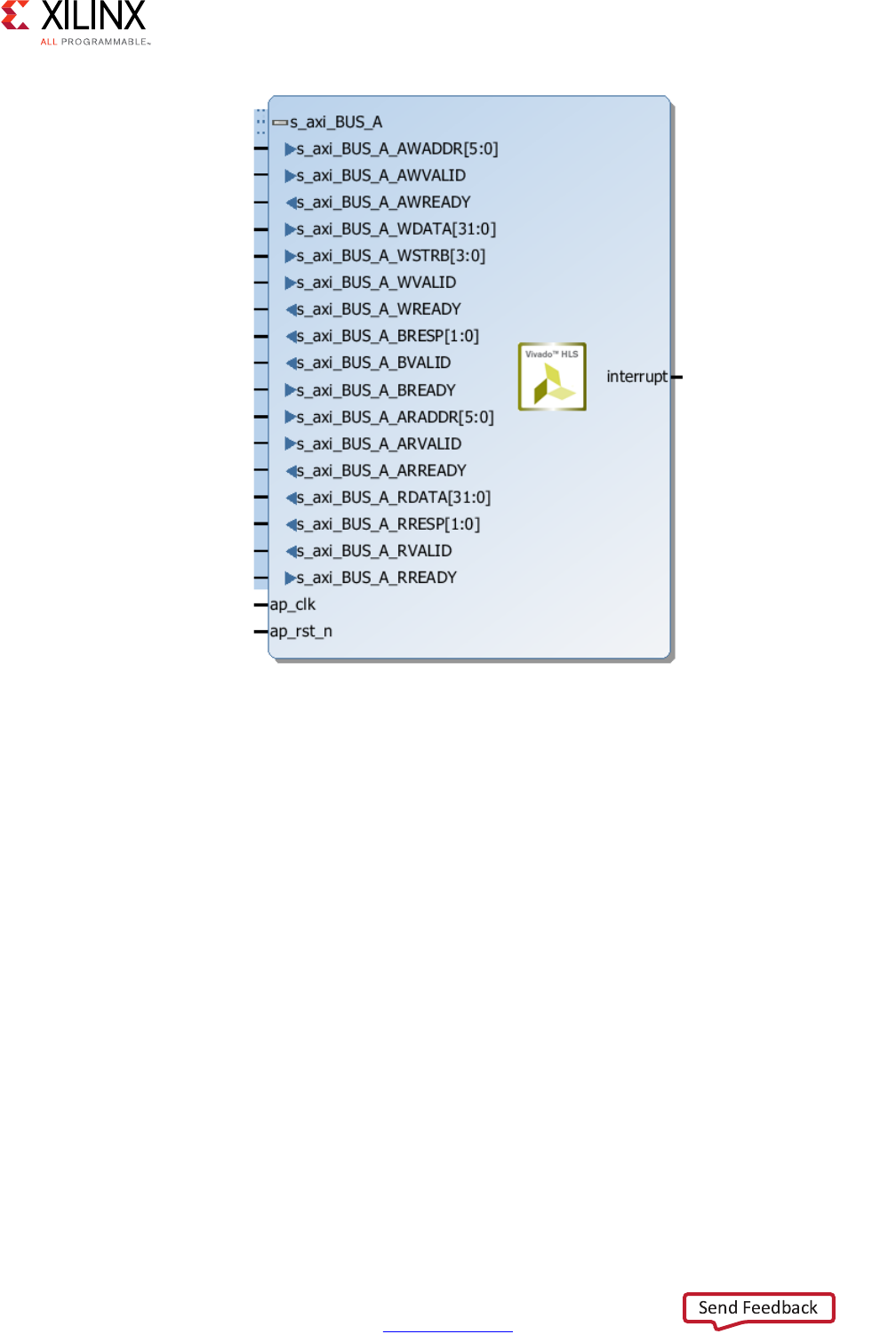
High-Level Synthesis 114
UG902 (v2017.1) April 5, 2017 www.xilinx.com
Chapter 1: High-Level Synthesis
Control Clock and Reset in AXI4-Lite Interfaces
By default, Vivado HLS uses the same clock for the AXI4-Lite interface and the synthesized
design. Vivado HLS connects all registers in the AXI4-Lite interface to the clock used for the
synthesized logic (ap_clk).
Optionally, you can use the INTERFACE directive clock option to specify a separate clock
for each AXI4-Lite port. When connecting the clock to the AXI4-Lite interface, you must use
the following protocols:
• AXI4-Lite interface clock must be synchronous to the clock used for the synthesized
logic (ap_clk). That is, both clocks must be derived from the same master generator
clock.
• AXI4-Lite interface clock frequency must be equal to or less than the frequency of the
clock used for the synthesized logic (ap_clk).
X-Ref Target - Figure 1-44
Figure 1-44: AXI4-Lite Slave Interfaces with Grouped RTL Ports

High-Level Synthesis 115
UG902 (v2017.1) April 5, 2017 www.xilinx.com
Chapter 1: High-Level Synthesis
If you use the clock option with the interface directive, you only need to specify the
clock option on one function argument in each bundle. Vivado HLS implements all other
function arguments in the bundle with the same clock and reset. Vivado HLS names the
generated reset signal with the prefix ap_rst_ followed by the clock name. The generated
reset signal is active Low independent of the config_rtl command. For more
information, see Controlling the Reset Behavior.
The following example shows how Vivado HLS groups function arguments a and b into an
AXI4-Lite port with a clock named AXI_clk1 and an associated reset port.
// Default AXI-Lite interface implemented with independent clock called AXI_clk1
#pragma HLS interface s_axilite port=a clock=AXI_clk1
#pragma HLS interface s_axilite port=b
In the following example, Vivado HLS groups function arguments c and d into AXI4-Lite
port CTRL1 with a separate clock called AXI_clk2 and an associated reset port.
// CTRL1 AXI-Lite bundle implemented with a separate clock (called AXI_clk2)
#pragma HLS interface s_axilite port=c bundle=CTRL1 clock=AXI_clk2
#pragma HLS interface s_axilite port=d bundle=CTRL1
C Driver Files
When an AXI4-Lite slave interface is implemented, a set of C driver files are automatically
created. These C driver files provide a set of APIs that can be integrated into any software
running on a CPU and used to communicate with the device via the AXI4-Lite slave
interface.
The C driver files are created when the design is packaged as IP in the IP Catalog. For more
details on packing IP, see Exporting the RTL Design.
Driver files are created for standalone and Linux modes. In standalone mode the drivers are
used in the same way as any other Xilinx standalone drivers. In Linux mode, copy all the C
files (.c) and header files (.h) files into the software project.
High-Level Synthesis 116
UG902 (v2017.1) April 5, 2017 www.xilinx.com
Chapter 1: High-Level Synthesis
The driver files and API functions derive their name from the top-level function for
synthesis. In the above example, the top-level function is called “example”. If the top-level
function was named “DUT” the name “example” would be replaced by “DUT” in the
following description. The driver files are created in the packaged IP (located in the impl
directory inside the solution).
In file xexample.h, two structs are defined.
•XExample_Config: This is used to hold the configuration information (base address of
each AXI4-Lite slave interface) of the IP instance.
•XExample: This is used to hold the IP instance pointer. Most APIs take this instance
pointer as the first argument.
The standard API implementations are provided in files xexample.c,
xexample_sinit.c,xexample_linux.c, and provide functions to perform the
following operations.
• Initialize the device
• Control the device and query its status
• Read/write to the registers
• Set up, monitor, and control the interrupts
Table 1-9: C Driver Files for a Design Named example
File Path Usage Mode Description
data/example.mdd Standalone Driver definition file.
data/example.tcl Standalone Used by SDK to integrate the software into an SDK
project.
src/xexample_hw.h Both Defines address offsets for all internal registers.
src/xexample.h Both API definitions
src/xexample.c Both Standard API implementations
src/xexample_sinit.c Standalone Initialization API implementations
src/xexample_linux.c Linux Initialization API implementations
src/Makefile Standalone Makefile

High-Level Synthesis 117
UG902 (v2017.1) April 5, 2017 www.xilinx.com
Chapter 1: High-Level Synthesis
The following table lists each of the API function provided in the C driver files.
Table 1-10: C Driver API Functions
API Function Description
XExample_Initialize This API will write value to InstancePtr which then can be used
in other APIs. It is recommended to call this API to initialize a
device except when an MMU is used in the system.
XExample_CfgInitialize Initialize a device configuration. When a MMU is used in the
system, replace the base address in the XDut_Config variable
with virtual base address before calling this function. Not for
use on Linux systems.
XExample_LookupConfig Used to obtain the configuration information of the device by
ID. The configuration information contain the physical base
address. Not for user on Linux.
XExample_Release Release the uio device in linux. Delete the mappings by
munmap: the mapping will automatically be deleted if the
process terminated. Only for use on Linux systems.
XExample_Start Start the device. This function will assert the ap_start port on
the device. Available only if there is ap_start port on the
device.
XExample_IsDone Check if the device has finished the previous execution: this
function will return the value of the ap_done port on the device.
Available only if there is an ap_done port on the device.
XExample_IsIdle Check if the device is in idle state: this function will return the
value of the ap_idle port. Available only if there is an ap_idle
port on the device.
XExample_IsReady Check if the device is ready for the next input: this function will
return the value of the ap_ready port. Available only if there is
an ap_ready port on the device.
XExample_Continue Assert port ap_continue. Available only if there is an
ap_continue port on the device.
XExample_EnableAutoRestart Enables “auto restart” on device. When this is set the device will
automatically start the next transaction when the current
transaction completes.
XExample_DisableAutoRestart Disable the “auto restart” function.
XExample_Set_ARG Write a value to port ARG (a scalar argument of the top
function). Available only if ARG is input port.
XExample_Set_ARG_vld Assert port ARG_vld. Available only if ARG is an input port and
implemented with an ap_hs or ap_vld interface protocol.
XExample_Set_ARG_ack Assert port ARG_ack. Available only if ARG is an output port and
implemented with an ap_hs or ap_ack interface protocol.
XExample_Get_ARG Read a value from ARG. Only available if port ARG is an output
port on the device.
XExample_Get_ARG_vld Read a value from ARG_vld. Only available if port ARG is an
output port on the device and implemented with an ap_hs or
ap_vld interface protocol.

High-Level Synthesis 118
UG902 (v2017.1) April 5, 2017 www.xilinx.com
Chapter 1: High-Level Synthesis
XExample_Get_ARG_ack Read a value from ARG_ack. Only available if port ARG is an
input port on the device and implemented with an ap_hs or
ap_ack interface protocol.
XExample_Get_ARG_BaseAddress Return the base address of the array inside the interface. Only
available when ARG is an array grouped into the AXI4-Lite
interface.
XExample_Get_ARG_HighAddress Return the address of the uppermost element of the array. Only
available when ARG is an array grouped into the AXI4-Lite
interface.
XExample_Get_ARG_TotalBytes Return the total number of bytes used to store the array. Only
available when ARG is an array grouped into the AXI4-Lite
interface.
Note: If the elements in the array are less than 16-bit, Vivado HLS
groups multiple elements into the 32-bit data width of the AXI4-Lite
interface. If the bit width of the elements exceeds 32-bit, Vivado HLS
stores each element over multiple consecutive addresses.
XExample_Get_ARG_BitWidth Return the bit width of each element in the array. Only available
when ARG is an array grouped into the AXI4-Lite interface.
Note: If the elements in the array are less than 16-bit, Vivado HLS
groups multiple elements into the 32-bit data width of the AXI4-Lite
interface. If the bit width of the elements exceeds 32-bit, Vivado HLS
stores each element over multiple consecutive addresses.
XExample_Get_ARG_Depth Return the total number of elements in the array. Only available
when ARG is an array grouped into the AXI4-Lite interface.
Note: If the elements in the array are less than 16-bit, Vivado HLS
groups multiple elements into the 32-bit data width of the AXI4-Lite
interface. If the bit width of the elements exceeds 32-bit, Vivado HLS
stores each element over multiple consecutive addresses.
XExample_Write_ARG_Words Write the length of a 32-bit word into the specified address of
the AXI4-Lite interface. This API requires the offset address
from BaseAddress and the length of the data to be stored. Only
available when ARG is an array grouped into the AXI4-Lite
interface.
XExample_Read_ARG_Words Read the length of a 32-bit word from the array. This API
requires the data target, the offset address from BaseAddress,
and the length of the data to be stored. Only available when
ARG is an array grouped into the AXI4-Lite interface.
XExample_Write_ARG_Bytes Write the length of bytes into the specified address of the
AXI4-Lite interface. This API requires the offset address from
BaseAddress and the length of the data to be stored. Only
available when ARG is an array grouped into the AXI4-Lite
interface.
XExample_Read_ARG_Bytes Read the length of bytes from the array. This API requires the
data target, the offset address from BaseAddress, and the
length of data to be loaded. Only available when ARG is an array
grouped into the AXI4-Lite interface.
Table 1-10: C Driver API Functions (Cont’d)
API Function Description

High-Level Synthesis 119
UG902 (v2017.1) April 5, 2017 www.xilinx.com
Chapter 1: High-Level Synthesis
IMPORTANT: The C driver APIs always use an unsigned 32-bit type (U32). You might be required to cast
the data in the C code into the expected type.
C Driver Files and Float Types
C driver files always use a data 32-bit unsigned integer (U32) for data transfers. In the
following example, the function uses float type arguments a and r1. It sets the value of a
and returns the value of r1:
float caculate(float a, float *r1)
{
#pragma HLS INTERFACE ap_vld register port=r1
#pragma HLS INTERFACE s_axilite port=a
#pragma HLS INTERFACE s_axilite port=r1
#pragma HLS INTERFACE s_axilite port=return
*r1 = 0.5f*a;
return (a>0);
}
XExample_InterruptGlobalEnable Enable the interrupt output. Interrupt functions are available
only if there is ap_start.
XExample_InterruptGlobalDisable Disable the interrupt output.
XExample_InterruptEnable Enable the interrupt source. There may be at most 2 interrupt
sources (source 0 for ap_done and source 1 for ap_ready)
XExample_InterruptDisable Disable the interrupt source.
XExample_InterruptClear Clear the interrupt status.
XExample_InterruptGetEnabled Check which interrupt sources are enabled.
XExample_InterruptGetStatus Check which interrupt sources are triggered.
Table 1-10: C Driver API Functions (Cont’d)
API Function Description

High-Level Synthesis 120
UG902 (v2017.1) April 5, 2017 www.xilinx.com
Chapter 1: High-Level Synthesis
After synthesis, Vivado HLS groups all ports into the default AXI4-Lite interface and creates
C driver files. However, as shown in the following example, the driver files use type U32:
// API to set the value of A
void XCaculate_SetA(XCaculate *InstancePtr, u32 Data) {
Xil_AssertVoid(InstancePtr != NULL);
Xil_AssertVoid(InstancePtr->IsReady == XIL_COMPONENT_IS_READY);
XCaculate_WriteReg(InstancePtr->Hls_periph_bus_BaseAddress,
XCACULATE_HLS_PERIPH_BUS_ADDR_A_DATA, Data);
}
// API to get the value of R1
u32 XCaculate_GetR1(XCaculate *InstancePtr) {
u32 Data;
Xil_AssertNonvoid(InstancePtr != NULL);
Xil_AssertNonvoid(InstancePtr->IsReady == XIL_COMPONENT_IS_READY);
Data = XCaculate_ReadReg(InstancePtr->Hls_periph_bus_BaseAddress,
XCACULATE_HLS_PERIPH_BUS_ADDR_R1_DATA);
return Data;
}
If these functions work directly with float types, the write and read values are not consistent
with expected float type. When using these functions in software, you can use the following
casts in the code:
float a=3.0f,r1;
u32 ua,ur1;
// cast float “a” to type U32
XCaculate_SetA(&calculate,*((u32*)&a));
ur1=XCaculate_GetR1(&caculate);
// cast return type U32 to float type for “r1”
r1=*((float*)&ur1);
For a complete description of the API functions, see AXI4-Lite Slave C Driver Reference in
Chapter 4.

High-Level Synthesis 121
UG902 (v2017.1) April 5, 2017 www.xilinx.com
Chapter 1: High-Level Synthesis
Controlling Hardware
The hardware header file xexample_hw.h (in this example) provides a complete list of the
memory mapped locations for the ports grouped into the AXI4-Lite slave interface.
// 0x00 : Control signals
// bit 0 - ap_start (Read/Write/SC)
// bit 1 - ap_done (Read/COR)
// bit 2 - ap_idle (Read)
// bit 3 - ap_ready (Read)
// bit 7 - auto_restart (Read/Write)
// others - reserved
// 0x04 : Global Interrupt Enable Register
// bit 0 - Global Interrupt Enable (Read/Write)
// others - reserved
// 0x08 : IP Interrupt Enable Register (Read/Write)
// bit 0 - Channel 0 (ap_done)
// bit 1 - Channel 1 (ap_ready)
// 0x0c : IP Interrupt Status Register (Read/TOW)
// bit 0 - Channel 0 (ap_done)
// others - reserved
// 0x10 : Data signal of a
// bit 7~0 - a[7:0] (Read/Write)
// others - reserved
// 0x14 : reserved
// 0x18 : Data signal of b
// bit 7~0 - b[7:0] (Read/Write)
// others - reserved
// 0x1c : reserved
// 0x20 : Data signal of c_i
// bit 7~0 - c_i[7:0] (Read/Write)
// others - reserved
// 0x24 : reserved
// 0x28 : Data signal of c_o
// bit 7~0 - c_o[7:0] (Read)
// others - reserved
// 0x2c : Control signal of c_o
// bit 0 - c_o_ap_vld (Read/COR)
// others - reserved
// (SC = Self Clear, COR = Clear on Read, TOW = Toggle on Write, COH = Clear on
Handshake)
To correctly program the registers in the AXI4-Lite slave interface, there is some
requirement to understand how the hardware ports operate. The block will operate with the
same port protocols described in Interface Synthesis.
For example, to start the block operation the ap_start register must be set to 1. The
device will then proceed and read any inputs grouped into the AXI4-Lite slave interface
from the register in the interface. When the block completes operation, the ap_done,
ap_idle and ap_ready registers will be set by the hardware output ports and the results
for any output ports grouped into the AXI4-Lite slave interface read from the appropriate
register. This is the same operation described in Figure 1-38.

High-Level Synthesis 122
UG902 (v2017.1) April 5, 2017 www.xilinx.com
Chapter 1: High-Level Synthesis
The implementation of function argument c in the example above also highlights the
importance of some understanding how the hardware ports are operate. Function
argument c is both read and written to, and is therefore implemented as separate input and
output ports c_i and c_o, as explained in Interface Synthesis.
The first recommended flow for programing the AXI4-Lite slave interface is for a one-time
execution of the function:
• Use the interrupt function to determine how you wish the interrupt to operate.
• Load the register values for the block input ports. In the above example this is
performed using API functions XExample_Set_a, XExample_Set_b, and
XExample_Set_c_i.
• Set the ap_start bit to 1 using XExample_Start to start executing the function.
This register is self-clearing as noted in the header file above. After one transaction, the
block will suspend operation.
• Allow the function to execute. Address any interrupts which are generated.
• Read the output registers. In the above example this is performed using API functions
XExample_Get_c_o_vld, to confirm the data is valid, and XExample_Get_c_o.
Note: The registers in the AXI4-Lite slave interface obey the same I/O protocol as the ports. In
this case, the output valid is set to logic 1 to indicate if the data is valid.
• Repeat for the next transaction.
The second recommended flow is for continuous execution of the block. In this mode, the
input ports included in the AXI4-Lite slave interface should only be ports which perform
configuration. The block will typically run must faster than a CPU. If the block must wait for
inputs, the block will spend most of its time waiting:
• Use the interrupt function to determine how you wish the interrupt to operate.
• Load the register values for the block input ports. In the above example this is
performed using API functions XExample_Set_a, XExample_Set_a and
XExample_Set_c_i.
• Set the auto-start function using API XExample_EnableAutoRestart
• Allow the function to execute. The individual port I/O protocols will synchronize the
data being processed through the block.
• Address any interrupts which are generated. The output registers could be accessed
during this operation but the data may change often.
• Use the API function XExample_DisableAutoRestart to prevent any more
executions.
• Read the output registers. In the above example this is performed using API functions
XExample_Get_c_o and XExample_Set_c_o_vld.

High-Level Synthesis 123
UG902 (v2017.1) April 5, 2017 www.xilinx.com
Chapter 1: High-Level Synthesis
Controlling Software
The API functions can be used in the software running on the CPU to control the hardware
block. An overview of the process is:
• Create an instance of the HW instance
• Look Up the device configuration
• Initialize the Device
• Set the input parameters of the HLS block
• Start the device and read the results
An abstracted versions of this process is shown below. Complete examples of the software
control are provided in the Zynq-7000 AP SoC tutorials noted in Table 1-4.
#include "xexample.h" // Device driver for HLS HW block
#include "xparameters.h"
// HLS HW instance
XExample HlsExample;
XExample_Config *ExamplePtr
int main() {
int res_hw;
// Look Up the device configuration
ExamplePtr = XExample_LookupConfig(XPAR_XEXAMPLE_0_DEVICE_ID);
if (!ExamplePtr) {
print("ERROR: Lookup of accelerator configuration failed.\n\r");
return XST_FAILURE;
}
// Initialize the Device
status = XExample_CfgInitialize(&HlsExample, ExamplePtr);
if (status != XST_SUCCESS) {
print("ERROR: Could not initialize accelerator.\n\r");
exit(-1);
}
//Set the input parameters of the HLS block
XExample_Set_a(&HlsExample, 42);
XExample_Set_b(&HlsExample, 12);
XExample_Set_c_i(&HlsExample, 1);
// Start the device and read the results
XExample_Start(&HlsExample);
do {
res_hw = XExample_Get_c_o(&HlsExample);
} while (XExample_Get_c_o(&HlsExample) == 0); // wait for valid data output
print("Detected HLS peripheral complete. Result received.\n\r");
}
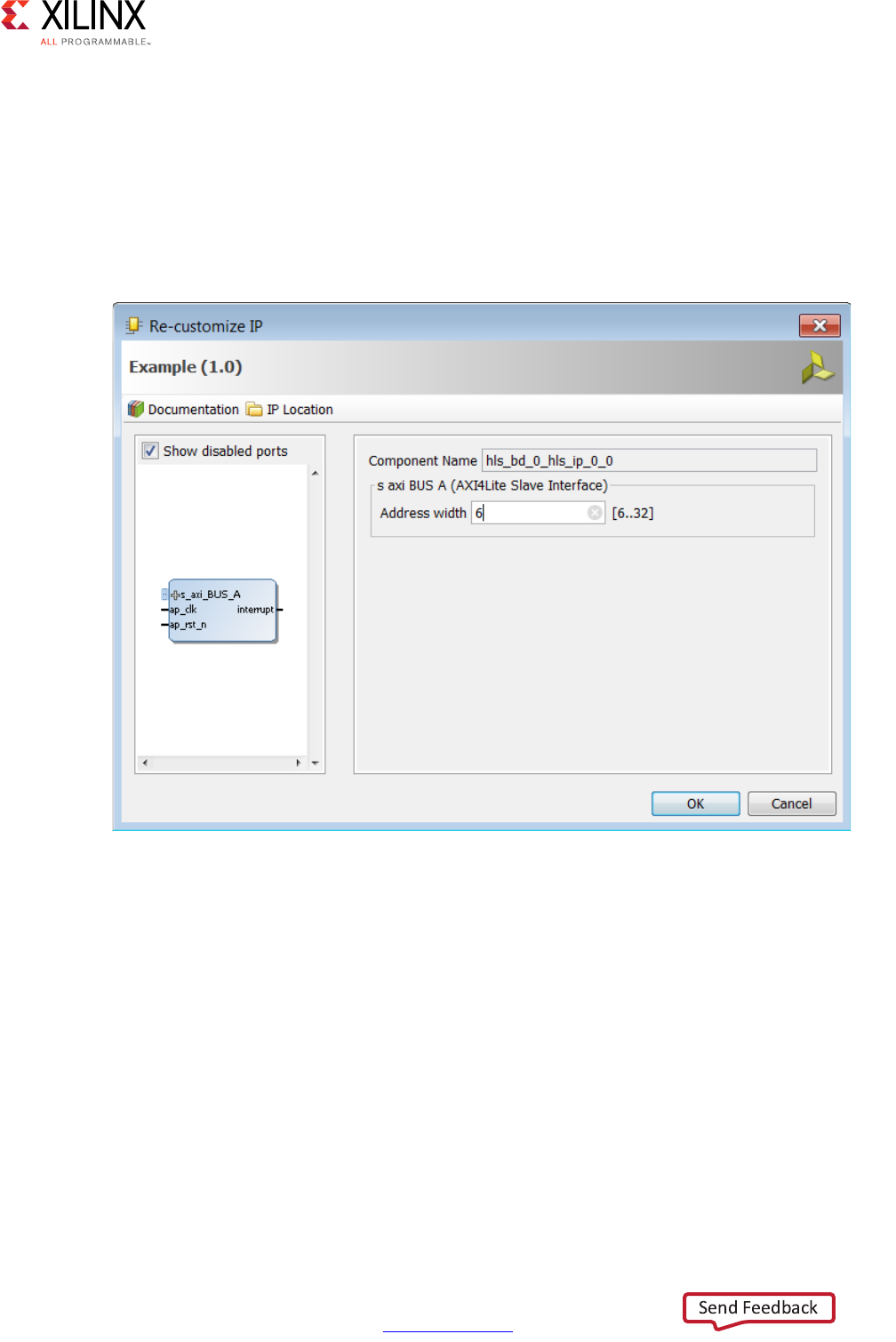
High-Level Synthesis 124
UG902 (v2017.1) April 5, 2017 www.xilinx.com
Chapter 1: High-Level Synthesis
Customizing AXI4-Lite Slave Interfaces in IP Integrator
When an HLS RTL design using an AXI4-Lite slave interface is incorporated into a design in
Vivado IP Integrator, you can customize the block. From the block diagram in IP Integrator,
select the HLS block, right-click with the mouse button and select Customize Block.
The address width is by default configured to the minimum required size. Modify this to
connect to blocks with address sizes less than 32-bit.
AXI4 Master Interface
You can use an AXI4 master interface on array or pointer/reference arguments, which
Vivado HLS implements in one of the following modes:
• Individual data transfers
• Burst mode data transfers
X-Ref Target - Figure 1-45
Figure 1-45: Customizing AXI4-Lite Slave Interfaces in IP Integrator

High-Level Synthesis 125
UG902 (v2017.1) April 5, 2017 www.xilinx.com
Chapter 1: High-Level Synthesis
With individual data transfers, Vivado HLS reads or writes a single element of data for each
address. The following example shows a single read and single write operation. In this
example, Vivado HLS generates an address on the AXI interface to read a single data value
and an address to write a single data value. The interface transfers one data value per
address.
void bus (int *d) {
static int acc = 0;
acc += *d;
*d = acc;
}
With burst mode transfers, Vivado HLS reads or writes data using a single base address
followed by multiple sequential data samples, which makes this mode capable of higher
data throughput. Burst mode of operation is possible when you use the C memcpy function
or a pipelined for loop.
Note: The C memcpy function is only supported for synthesis when used to transfer data to or from
a top-level function argument specified with an AXI4 master interface.
The following example shows a copy of burst mode using the memcpy function. The
top-level function argument a is specified as an AXI4 master interface.
void example(volatile int *a){
#pragma HLS INTERFACE m_axi depth=50 port=a
#pragma HLS INTERFACE s_axilite port=return
//Port a is assigned to an AXI4 master interface
int i;
int buff[50];
//memcpy creates a burst access to memory
memcpy(buff,(const int*)a,50*sizeof(int));
for(i=0; i < 50; i++){
buff[i] = buff[i] + 100;
}
memcpy((int *)a,buff,50*sizeof(int));
}
When this example is synthesized, it results in the interface shown in the following figure.
Note: In this figure, the AXI4 interfaces are collapsed.
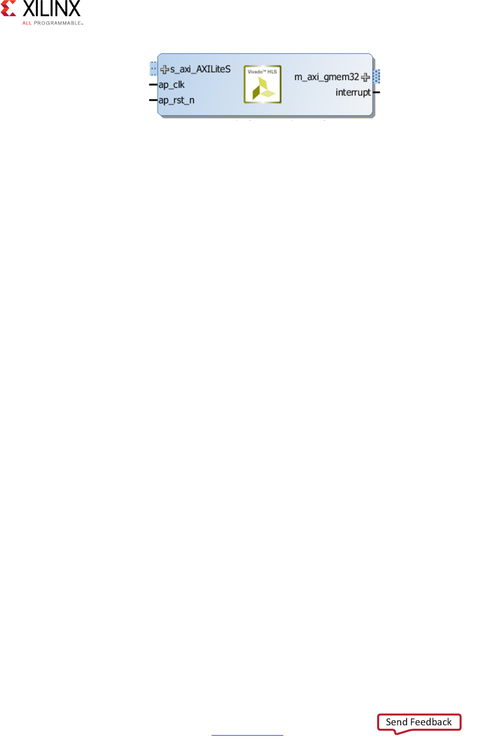
High-Level Synthesis 126
UG902 (v2017.1) April 5, 2017 www.xilinx.com
Chapter 1: High-Level Synthesis
The following example shows the same code as the preceding example but uses a for loop
to copy the data out:
void example(volatile int *a){
#pragma HLS INTERFACE m_axi depth=50 port=a
#pragma HLS INTERFACE s_axilite port=return
//Port a is assigned to an AXI4 master interface
int i;
int buff[50];
//memcpy creates a burst access to memory
memcpy(buff,(const int*)a,50*sizeof(int));
for(i=0; i < 50; i++){
buff[i] = buff[i] + 100;
}
for(i=0; i < 50; i++){
#pragma HLS PIPELINE
a[i] = buff[i];
}
}
When using a for loop to implement burst reads or writes, follow these requirements:
• Pipeline the loop
• Access addresses in increasing order
• Do not place accesses inside a conditional statement
• For nested loops, do not flatten loops, because this inhibits the burst operation
Note: Only one read and one write is allowed in a for loop unless the ports are bundled in different
AXI ports. The following example shows how to perform two reads in burst mode using different AXI
interfaces.
X-Ref Target - Figure 1-46
Figure 1-46: AXI4 Interface

High-Level Synthesis 127
UG902 (v2017.1) April 5, 2017 www.xilinx.com
Chapter 1: High-Level Synthesis
In the following example, Vivado HLS implements the port reads as burst transfers. Port a
is specified without using the bundle option and is implemented in the default AXI
interface. Port b is specified using a named bundle and is implemented in a separate AXI
interface called d2_port.
void example(volatile int *a, int *b){
#pragma HLS INTERFACE s_axilite port=return
#pragma HLS INTERFACE m_axi depth=50 port=a
#pragma HLS INTERFACE m_axi depth=50 port=b bundle=d2_port
int i;
int buff[50];
//copy data in
for(i=0; i < 50; i++){
#pragma HLS PIPELINE
buff[i] = a[i] + b[i];
}
...
}
Controlling AXI4 Burst Behavior
An optimal AXI4 interface is one in which the design never stalls while waiting to access the
bus, and after bus access is granted, the bus never stalls while waiting for the design to
read/write. To create the optimal AXI4 interface, the following options are provided in the
INTERFACE directive to specify the behavior of the bursts and optimize the efficiency of the
AXI4 interface.
Some of these options use internal storage to buffer data and may have an impact on area
and resources:
•latency: Specifies the expected latency of the AXI4 interface, allowing the design to
initiate a bus request a number of cycles (latency) before the read or write is expected.
If this figure it too low, the design will be ready too soon and may stall waiting for the
bus. If this figure is too high, bus access may be granted but the bus may stall waiting
on the design to start the access.
•max_read_burst_length: Specifies the maximum number of data values read
during a burst transfer.
•num_read_outstanding: Specifies how many read requests can be made to the AXI4
bus, without a response, before the design stalls. This implies internal storage in the
design, a FIFO of size:
num_read_outstanding*max_read_burst_length*word_size.
•max_write_burst_length: Specifies the maximum number of data values written
during a burst transfer.

High-Level Synthesis 128
UG902 (v2017.1) April 5, 2017 www.xilinx.com
Chapter 1: High-Level Synthesis
•num_write_outstanding: Specifies how many write requests can be made to the
AXI4 bus, without a response, before the design stalls. This implies internal storage in
the design, a FIFO of size:
num_read_outstanding*max_read_burst_length*word_size
The following example can be used to help explain these options:
#pragma HLS interface m_axi port=input offset=slave bundle=gmem0
depth=1024*1024*16/(512/8)
latency=100
num_read_outstanding=32
num_write_outstanding=32
max_read_burst_length=16
max_write_burst_length=16
The interface is specified as having a latency of 100. Vivado HLS seeks to schedule the
request for burst access 100 clock cycles before the design is ready to access the AXI4 bus.
To further improve bus efficiency, the options num_write_outstanding and
num_read_outstanding ensure the design contains enough buffering to store up to 32
read and write accesses. This allows the design to continue processing until the bus
requests are serviced. Finally, the options max_read_burst_length and
max_write_burst_length ensure the maximum burst size is 16 and that the AXI4
interface does not hold the bus for longer than this.
These options allow the behavior of the AXI4 interface to be optimized for the system in
which it will operate. The efficiency of the operation does depend on these values being set
accuracy.
Creating an AXI4 Interface with 64-bit Address Capability
By default, Vivado HLS implements the AXI4 port with a 32-bit address bus. Optionally, you
can implement the AXI4 interface with a 64-bit address bus using the m_axi_addr64
interface configuration option as follows:
1. Select Solution > Solution Settings.
2. In the Solution Settings dialog box, click the General category, and click Add.
3. In the Add Command dialog box, select config_interface, and enable m_axi_addr64.
IMPORTANT: When you select the m_axi_addr64 option, Vivado HLS implements all AXI4 interfaces in
the design with a 64-bit address bus.

High-Level Synthesis 129
UG902 (v2017.1) April 5, 2017 www.xilinx.com
Chapter 1: High-Level Synthesis
Controlling the Address Offset in an AXI4 Interface
By default, the AXI4 master interface starts all read and write operations from address
0x00000000. For example, given the following code, the design reads data from addresses
0x00000000 to 0x000000c7 (50 32-bit words, gives 200 bytes), which represents 50 address
values. The design then writes data back to the same addresses.
void example(volatile int *a){
#pragma HLS INTERFACE m_axi depth=50 port=a
#pragma HLS INTERFACE s_axilite port=return bundle=AXILiteS
int i;
int buff[50];
memcpy(buff,(const int*)a,50*sizeof(int));
for(i=0; i < 50; i++){
buff[i] = buff[i] + 100;
}
memcpy((int *)a,buff,50*sizeof(int));
}
To apply an address offset, use the -offset option with the INTERFACE directive, and
specify one of the following options:
•off: Does not apply an offset address. This is the default.
•direct: Adds a 32-bit port to the design for applying an address offset.
•slave: Adds a 32-bit register inside the AXI4-Lite interface for applying an address
offset.
In the final RTL, Vivado HLS applies the address offset directly to any read or write address
generated by the AXI4 master interface. This allows the design to access any address
location in the system.
If you use the slave option in an AXI interface, you must use an AXI4-Lite port on the
design interface. Xilinx recommends that you implement the AXI4-Lite interface using the
following pragma:
#pragma HLS INTERFACE s_axilite port=return
In addition, if you use the slave option and you used several AXI4-Lite interfaces, you
must ensure that the AXI master port offset register is bundled into the correct AXI4-Lite
interface. In the following example, port a is implemented as an AXI master interface with
an offset and AXI4-Lite interfaces called AXI_Lite_1 and AXI_Lite_2:
#pragma HLS INTERFACE m_axi port=a depth=50 offset=slave
#pragma HLS INTERFACE s_axilite port=return bundle=AXI_Lite_1
#pragma HLS INTERFACE s_axilite port=b bundle=AXI_Lite_2
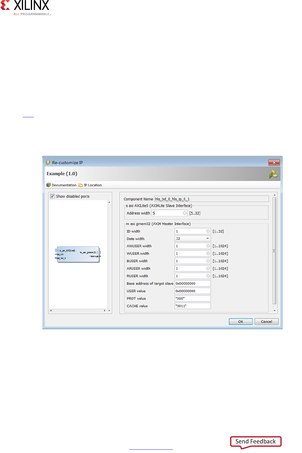
High-Level Synthesis 130
UG902 (v2017.1) April 5, 2017 www.xilinx.com
Chapter 1: High-Level Synthesis
The following INTERFACE directive is required to ensure that the offset register for port a is
bundled into the AXI4-Lite interface called AXI_Lite_1:
#pragma HLS INTERFACE s_axilite port=a bundle=AXI_Lite_1
Customizing AXI4 Master Interfaces in IP Integrator
When you incorporate an HLS RTL design that uses an AXI4 master interface into a design
in the Vivado IP Integrator, you can customize the block. From the block diagram in IP
Integrator, select the HLS block, right-click, and select Customize Block to customize any
of the settings provided. A complete description of the AXI4 parameters is provided in this
link in the AXI Reference Guide (UG1037)[Ref 8].
The following figure shows the Re-Customize IP dialog box for the design shown in
Figure 1-46. This design includes an AXI4-Lite port.
X-Ref Target - Figure 1-47
Figure 1-47: Customizing AXI4 Master Interfaces in IP Integrator

High-Level Synthesis 131
UG902 (v2017.1) April 5, 2017 www.xilinx.com
Chapter 1: High-Level Synthesis
Managing Interfaces with SSI Technology Devices
Certain Xilinx devices use stacked silicon interconnect (SSI) technology. In these devices, the
total available resources are divided over multiple super logic regions (SLRs). The
connections between SLRs use super long line (SSL) routes. SSL routes incur delays costs
that are typically greater than standard FPGA routing. To ensure designs operate at
maximum performance, use the following guidelines:
• Register all signals that cross between SLRs at both the SLR output and SLR input.
• You do not need to register a signal if it enters or exits an SLR via an I/O buffer.
• Ensure that the logic created by Vivado HLS fits within a single SLR.
Note: When you select an SSI technology device as the target technology, the utilization report
includes details on both the SLR usage and the total device usage.
If the logic is contained within a single SLR device, Vivado HLS provides a register_io
option to the config_interface command. This option provides a way to automatically
register all block inputs, outputs, or both. This option is only required for scalars. All array
ports are automatically registered.
The settings for the register_io option are:
•off: None of the input or outputs are registered.
•scalar_in: All inputs are registered.
•scalar_out: All outputs are registered.
•scalar_all: All input and outputs are registered.
Note: Using the register_io option with block-level floorplanning of the RTL ensures that logic
targeted to an SSI technology device executes at the maximum clock rate.
Optimizing the Design
This section outlines the various optimizations and techniques you can use to direct Vivado
HLS to produce a micro-architecture that satisfies the desired performance and area goals.

High-Level Synthesis 132
UG902 (v2017.1) April 5, 2017 www.xilinx.com
Chapter 1: High-Level Synthesis
The following table lists the optimization directives provided by Vivado HLS.
Table 1-11: Vivado HLS Optimization Directives
Directive Description
ALLOCATION Specify a limit for the number of operations, cores or
functions used. This can force the sharing or hardware
resources and may increase latency
ARRAY_MAP Combines multiple smaller arrays into a single large array
to help reduce block RAM resources.
ARRAY_PARTITION Partitions large arrays into multiple smaller arrays or into
individual registers, to improve access to data and remove
block RAM bottlenecks.
ARRAY_RESHAPE Reshape an array from one with many elements to one with
greater word-width. Useful for improving block RAM
accesses without using more block RAM.
CLOCK For SystemC designs multiple named clocks can be
specified using the create_clock command and applied
to individual SC_MODULEs using this directive.
DATA_PACK Packs the data fields of a struct into a single scalar with a
wider word width.
DATAFLOW Enables task level pipelining, allowing functions and loops
to execute concurrently. Used to minimize interval.
DEPENDENCE Used to provide additional information that can overcome
loop-carry dependencies and allow loops to be pipelined
(or pipelined with lower intervals).
EXPRESSION_BALANCE Allows automatic expression balancing to be turned off.
FUNCTION_INSTANTIATE Allows different instances of the same function to be locally
optimized.
INLINE Inlines a function, removing all function hierarchy. Used to
enable logic optimization across function boundaries and
improve latency/interval by reducing function call
overhead.
INTERFACE Specifies how RTL ports are created from the function
description.
LATENCY Allows a minimum and maximum latency constraint to be
specified.
LOOP_FLATTEN Allows nested loops to be collapsed into a single loop with
improved latency.
LOOP_MERGE Merge consecutive loops to reduce overall latency, increase
sharing and improve logic optimization.
LOOP_TRIPCOUNT Used for loops which have variables bounds. Provides an
estimate for the loop iteration count. This has no impact on
synthesis, only on reporting.
OCCURRENCE Used when pipelining functions or loops, to specify that the
code in a location is executed at a lesser rate than the code
in the enclosing function or loop.

High-Level Synthesis 133
UG902 (v2017.1) April 5, 2017 www.xilinx.com
Chapter 1: High-Level Synthesis
In addition to the optimization directives, Vivado HLS provides a number of configuration
settings. Configurations settings are used to change the default behavior of synthesis. The
configuration settings are shown in the following table.
PIPELINE Reduces the initiation interval by allowing the concurrent
execution of operations within a loop or function.
PROTOCOL This commands specifies a region of the code to be a
protocol region. A protocol region can be used to manually
specify an interface protocol.
RESET This directive is used to add or remove reset on a specific
state variable (global or static).
RESOURCE Specify that a specific library resource (core) is used to
implement a variable (array, arithmetic operation or
function argument) in the RTL.
STREAM Specifies that a specific array is to be implemented as a
FIFO or RAM memory channel during dataflow
optimization.
TOP The top-level function for synthesis is specified in the
project settings. This directive may be used to specify any
function as the top-level for synthesis. This then allows
different solutions within the same project to be specified
as the top-level function for synthesis without needing to
create a new project.
UNROLL Unroll for-loops to create multiple independent operations
rather than a single collection of operations.
Table 1-12: Vivado HLS Configurations
GUI Directive Description
Config Array Partition This configuration determines how arrays are partitioned,
including global arrays and if the partitioning impacts array
ports.
Config Bind Determines the effort level to use during the synthesis
binding phase and can be used to globally minimize the
number of operations used.
Config Compile Controls synthesis specific optimizations such as the
automatic loop pipelining and floating point math
optimizations.
Config Dataflow This configuration specifies the default memory channel
and FIFO depth in dataflow optimization.
Config Interface This configuration controls I/O ports not associated with
the top-level function arguments and allows unused ports
to be eliminated from the final RTL.
Table 1-11: Vivado HLS Optimization Directives (Cont’d)
Directive Description

High-Level Synthesis 134
UG902 (v2017.1) April 5, 2017 www.xilinx.com
Chapter 1: High-Level Synthesis
Details on how to apply the optimizations and configurations is provided in Applying
Optimization Directives. The configurations are accessed using the menu Solution >
Solution Settings > General and selecting the configuration using the Add button.
The optimizations are presented in the context of how they are typically applied on a
design.
The Clock, Reset and RTL output are discussed together. The clock frequency along with the
target device is the primary constraint which drives optimization. Vivado HLS seeks to place
as many operations from the target device into each clock cycle. The reset style used in the
final RTL is controlled, along setting such as the FSM encoding style, using the config_rtl
configuration.
The primary optimizations for Optimizing for Throughput are presented together in the
manner in which they are typically used: pipeline the tasks to improve performance,
improve the data flow between tasks and optimize structures to improve address issues
which may limit performance.
Optimizing for Latency uses the techniques of latency constraints and the removal of loop
transitions to reduce the number of clock cycles required to complete.
A focus on how operations are implemented - controlling the number of operations and
how those operations are implemented in hardware - is the principal technique for
improving the area.
Clock, Reset, and RTL Output
Specifying the Clock Frequency
For C and C++ designs only a single clock is supported. The same clock is applied to all
functions in the design.
For SystemC designs, each SC_MODULE may be specified with a different clock. To specify
multiple clocks in a SystemC design, use the -name option of the create_clock
command to create multiple named clocks and use the CLOCK directive or pragma to
specify which function contains the SC_MODULE to be synthesized with the specified clock.
Each SC_MODULE can only be synthesized using a single clock: clocks may be distributed
through functions, such as when multiple clocks are connected from the top-level ports to
individual blocks, but each SC_MODULE can only be sensitive to a single clock.
Config RTL Provides control over the output RTL including file and
module naming, reset style and FSM encoding.
Config Schedule Determines the effort level to use during the synthesis
scheduling phase and the verbosity of the output
messages
Table 1-12: Vivado HLS Configurations (Cont’d)
GUI Directive Description
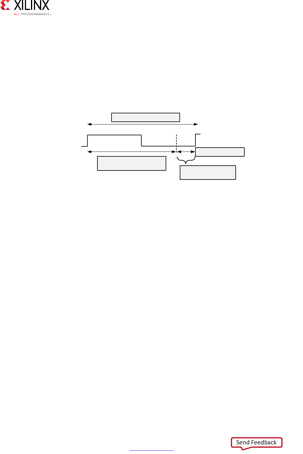
High-Level Synthesis 135
UG902 (v2017.1) April 5, 2017 www.xilinx.com
Chapter 1: High-Level Synthesis
The clock period, in ns, is set in the Solutions > Solutions Setting. Vivado HLS uses the
concept of a clock uncertainty to provide a user defined timing margin. Using the clock
frequency and device target information Vivado HLS estimates the timing of operations in
the design but it cannot know the final component placement and net routing: these
operations are performed by logic synthesis of the output RTL. As such, Vivado HLS cannot
know the exact delays.
To calculate the clock period used for synthesis, Vivado HLS subtracts the clock uncertainty
from the clock period, as shown in the following figure.
This provides a user specified margin to ensure downstream processes, such as logic
synthesis and place & route, have enough timing margin to complete their operations. If
the FPGA device is mostly utilized the placement of cells and routing of nets to connect the
cells might not be ideal and might result in a design with larger than expected timing
delays. For a situation such as this, an increased timing margin ensures Vivado HLS does not
create a design with too much logic packed into each clock cycle and allows RTL synthesis
to satisfy timing in cases with less than ideal placement and routing options.
By default, the clock uncertainty is 12.5% of the cycle time. The value can be explicitly
specified beside the clock period.
Vivado HLS aims to satisfy all constraints: timing, throughput, latency. However, if a
constraints cannot be satisfied, Vivado HLS always outputs an RTL design.
If the timing constraints inferred by the clock period cannot be met Vivado HLS issues
message SCHED-644, as shown below, and creates a design with the best achievable
performance.
@W [SCHED-644] Max operation delay (<operation_name> 2.39ns) exceeds the effective
cycle time
Even if Vivado HLS cannot satisfy the timing requirements for a particular path, it still
achieves timing on all other paths. This behavior allows you to evaluate if higher
optimization levels or special handling of those failing paths by downstream logic
syntheses can pull-in and ultimately satisfy the timing.
X-Ref Target - Figure 1-48
Figure 1-48: Clock Period and Margin
&ORFN3HULRG
(IIHFWLYH&ORFN3HULRG
XVHGE\9LYDGR+/6
&ORFN8QFHUWDLQW\
0DUJLQIRU/RJLF
6\QWKHVLVDQG35
;

High-Level Synthesis 136
UG902 (v2017.1) April 5, 2017 www.xilinx.com
Chapter 1: High-Level Synthesis
IMPORTANT: It is important to review the constraint report after synthesis to determine if all
constraints is met: the fact that Vivado HLS produces an output design does not guarantee the design
meets all performance constraints. Review the “Performance Estimates” section of the design report.
The option relax_ii_for_timing of the config_schedule command can be used to
change the default timing behavior. When this option is specified, Vivado HLS automatically
relaxes the II for any pipeline directive when it detects a path is failing to meet the clock
period. This option only applies to cases where the PIPELINE directive is specified without
an II value (and an II=1 is implied). If the II value is explicitly specified in the PIPELINE
directive, the relax_ii_for_timing option has no effect.
A design report is generated for each function in the hierarchy when synthesis completes
and can be viewed in the solution reports folder. The worse case timing for the entire design
is reported as the worst case in each function report. There is no need to review every
report in the hierarchy.
If the timing violations are too severe to be further optimized and corrected by downstream
processes, review the techniques for specifying an exact latency and specifying exact
implementation cores before considering a faster target technology.
Specifying the Reset
Typically the most important aspect of RTL configuration is selecting the reset behavior.
When discussing reset behavior it is important to understand the difference between
initialization and reset.
Initialization Behavior
In C, variables defined with the static qualifier and those defined in the global scope, are by
default initialized to zero. Optionally, these variables may be assigned a specific initial
value. For these type of variables, the initial value in the C code is assigned at compile time
(at time zero) and never again. In both cases, the same initial value is implemented in the
RTL.
• During RTL simulation the variables are initialized with the same values as the C code.
• The same variables are initialized in the bitstream used to program the FPGA. When the
device powers up, the variables will start in their initialized state.
The variables start with the same initial state as the C code. However, there is no way to
force a return to this initial state. To return to their initial state the variables must be
implemented with a reset.
IMPORTANT: Top-level function arguments may be implemented in an AXI4-Lite interface. Since there
is no way to provide an initial value in C/C++ for function arguments, these variable cannot be
initialized in the RTL as doing so would create an RTL design with different functional behavior from the
C/C++ code which would fail to verify during C/RTL co-simulation.
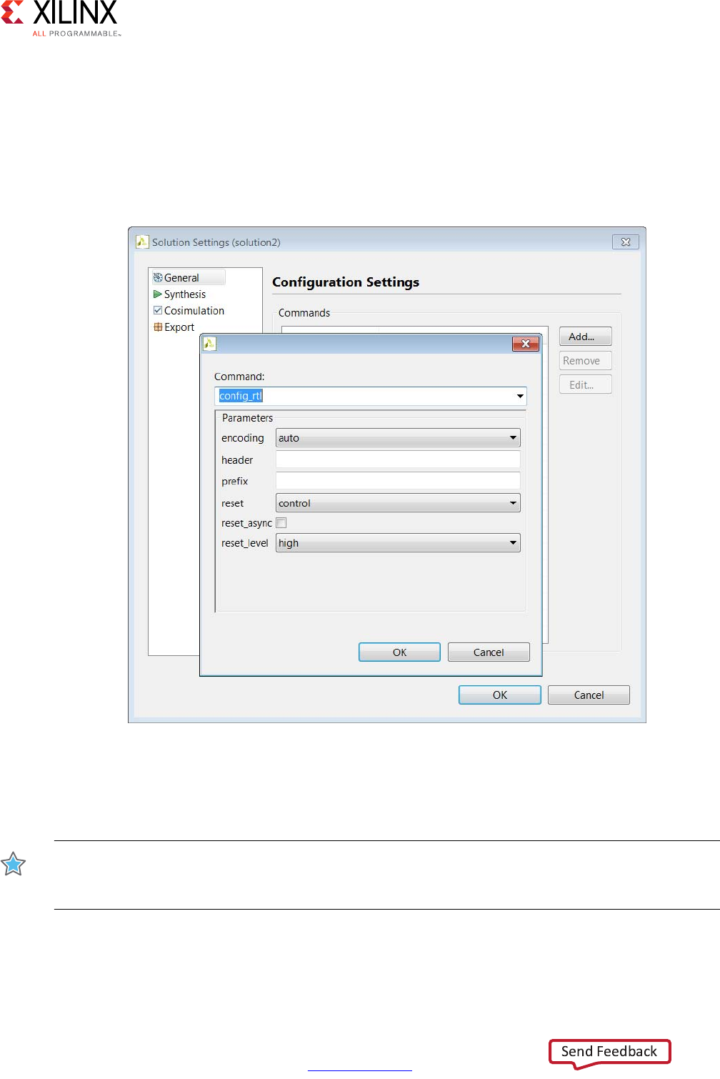
High-Level Synthesis 137
UG902 (v2017.1) April 5, 2017 www.xilinx.com
Chapter 1: High-Level Synthesis
Controlling the Reset Behavior
The reset port is used in an FPGA to return the registers and block RAM connected to the
reset port to an initial value any time the reset signal is applied. The presence and behavior
of the RTL reset port is controlled using the config_rtl configuration shown in the
following figure. To access this configuration, select Solution > Solution Settings >
General > Add > config_rtl.
The reset settings include the ability to set the polarity of the reset and whether the reset is
synchronous or asynchronous but more importantly it controls, through the reset option,
which registers are reset when the reset signal is applied.
IMPORTANT: When AXI4 interfaces are used on a design the reset polarity is automatically changed to
active-Low irrespective of the setting in the config_rtl configuration. This is required by the AXI4
standard.
X-Ref Target - Figure 1-49
Figure 1-49: RTL Configurations

High-Level Synthesis 138
UG902 (v2017.1) April 5, 2017 www.xilinx.com
Chapter 1: High-Level Synthesis
The reset option has four settings:
•none: No reset is added to the design.
•control: This is the default and ensures all control registers are reset. Control registers
are those used in state machines and to generate I/O protocol signals. This setting
ensures the design can immediately start its operation state.
•state: This option adds a reset to control registers (as in the control setting) plus any
registers or memories derived from static and global variables in the C code. This
setting ensures static and global variable initialized in the C code are reset to their
initialized value after the reset is applied.
•all: This adds a reset to all registers and memories in the design.
Finer grain control over reset is provided through the RESET directive. If a variable is a static
or global, the RESET directive is used to explicitly add a reset, or the variable can be
removed from those being reset by using the RESET directive’s off option. This can be
particularly useful when static or global arrays are present in the design.
IMPORTANT: Is is important when using the reset state or all option to consider the effect on
arrays.
Initializing and Resetting Arrays
Arrays are often defined as static variables, which implies all elements be initialized to zero,
and arrays are typically implemented as block RAM. When reset options state or all are
used, it forces all arrays implemented as block RAM to be returned to their initialized state
after reset. This may result in two very undesirable conditions in the RTL design:
• Unlike a power-up initialization, an explicit reset requires the RTL design iterate
through each address in the block RAM to set the value: this can take many clock cycles
if N is large and require more area resources to implement.
• A reset is added to every array in the design.
To prevent placing reset logic onto every such block RAM and incurring the cycle overhead
to reset all elements in the RAM:
•Use the default control reset mode and use the RESET directive to specify individual
static or global variables to be reset.
• Alternatively, use reset mode state and remove the reset from specific static or global
variables using the off option to the RESET directive.

High-Level Synthesis 139
UG902 (v2017.1) April 5, 2017 www.xilinx.com
Chapter 1: High-Level Synthesis
RTL Output
Various characteristics of the RTL output by Vivado HLS can be controlled using the
config_rtl configuration shown in Figure 1-49.
• Specify the type of FSM encoding used in the RTL state machines.
• Add an arbitrary comment string, such as a copyright notice, to all RTL files using the
-header option.
• Specify a unique name with the prefix option which is added to all RTL output file
names.
• Force the RTL ports to use lower case names.
The default FSM coding is style is onehot. Other possible options are auto, binary, and
gray. If you select auto, Vivado HLS implements the style of encoding using the onehot
default, but Vivado Design Suite might extract and re-implement the FSM style during logic
synthesis. If you select any other encoding style (binary, onehot, gray), the encoding
style cannot be re-optimized by Xilinx logic synthesis tools.
The names of the RTL output files are derived from the name of the top-level function for
synthesis. If different RTL blocks are created from the same top-level function, the RTL files
will have the same name and cannot be combined in the same RTL project. The prefix
option allows RTL files generated from the same top-level function (and which by default
have the same name as the top-level function) to be easily combined in the same directory.
The lower_case_name option ensures the only lower case names are used in the output
RTL. This option ensures the IO protocol ports created by Vivado HLS, such as those for AXI
interfaces, are specified as s_axis_<port>_tdata in the final RTL rather than the default
port name of s_axis_<port>_TDATA.
Optimizing for Throughput
Use the following optimizations to improve throughput or reduce the initiation interval.
Task Pipelining
Pipelining allows operations to happen concurrently: the task does not have to complete all
operations before it begin the next operation. Pipelining is applied to functions and loops.
The throughput improvements in function pipelining are shown in the following figure.
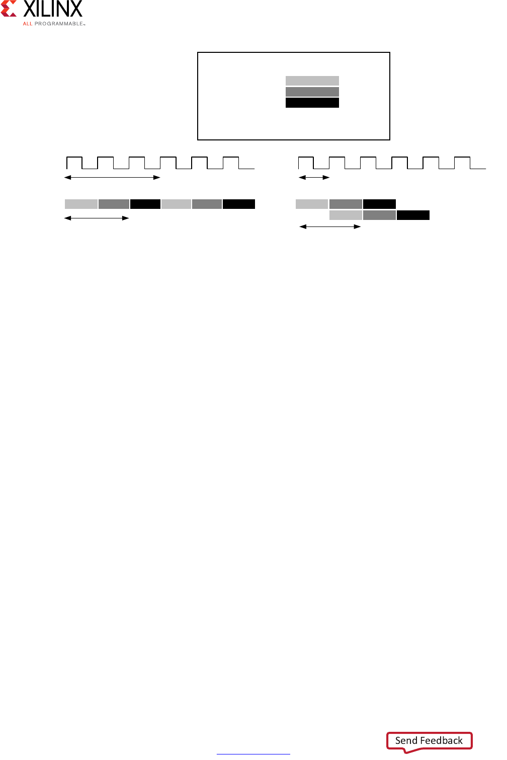
High-Level Synthesis 140
UG902 (v2017.1) April 5, 2017 www.xilinx.com
Chapter 1: High-Level Synthesis
Without pipelining the function reads an input every 3 clock cycles and outputs a value
every 2 clock cycles. The function has an Initiation Interval (II) of 3 and a latency of 2. With
pipelining, a new input is read every cycle (II=1) with no change to the output latency or
resources used.
Loop pipelining allows the operations in a loop to be implemented in a concurrent manner
as shown in the following figure. In this figure, (A) shows the default sequential operation
where there are 3 clock cycles between each input read (II=3), and it requires 8 clock cycles
before the last output write is performed.
In the pipelined version of the loop shown in (B), a new input sample is read every cycle
(II=1) and the final output is written after only 4 clock cycles: substantially improving both
the II and latency while using the same hardware resources.
X-Ref Target - Figure 1-50
Figure 1-50: Function Pipelining Behavior
void func(…) {
op_Read;
op_Compute;
op_Write;
}
RD
CMP
WR
3 cycles
RD CMP WR RD CMP WR
1 cycle
RD CMP WR
2 cycles
RD CMP WR
2 cycles
(A) Without Function Pipelining (B) With Function Pipelining
;
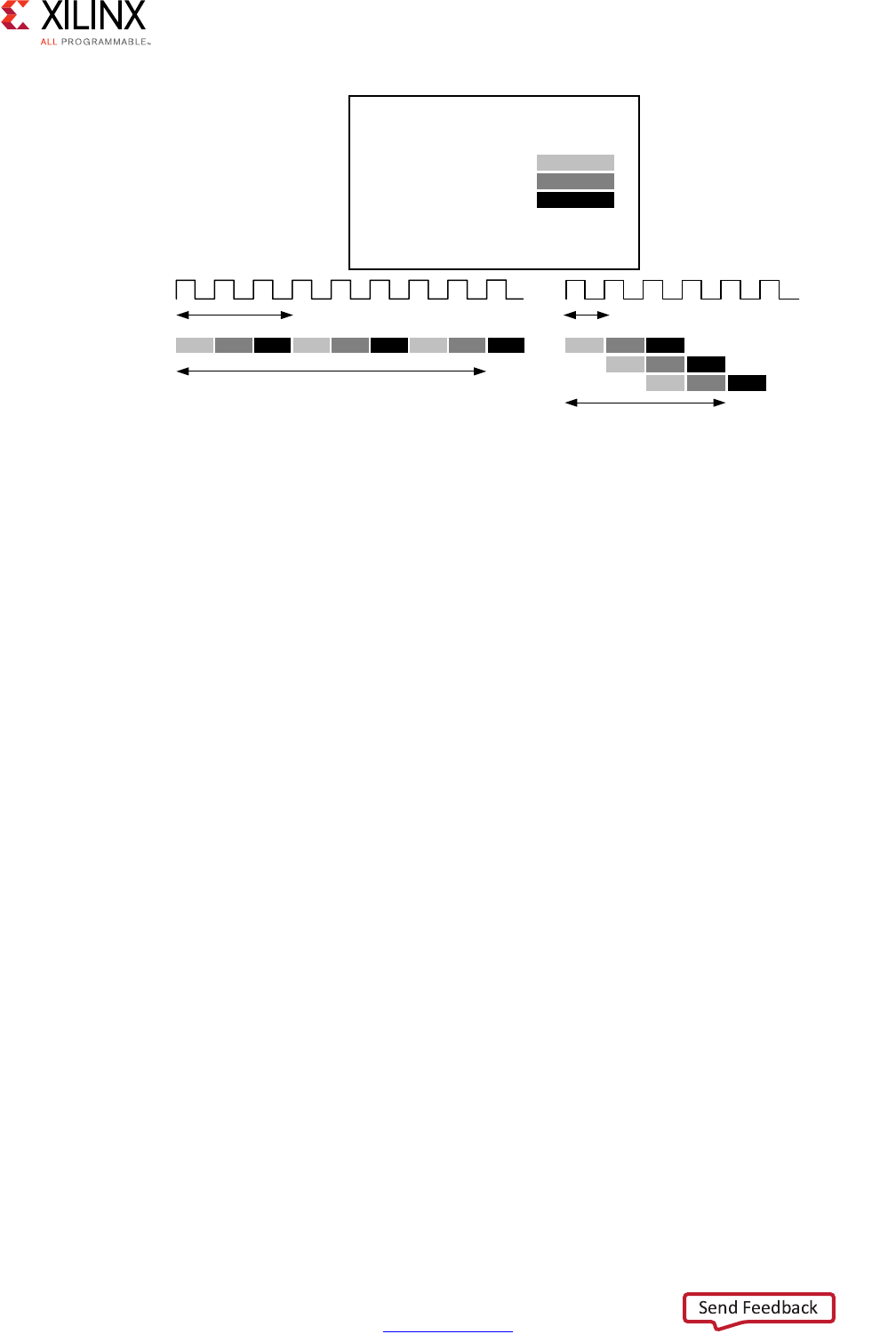
High-Level Synthesis 141
UG902 (v2017.1) April 5, 2017 www.xilinx.com
Chapter 1: High-Level Synthesis
Tasks are pipelined using the PIPELINE directive. The initiation interval defaults to 1 if not
specified but may be explicitly specified.
Pipelining is applied to the specified task not to the hierarchy below: all loops in the
hierarchy below are automatically unrolled. Any sub-functions in the hierarchy below the
specified task must be pipelined individually. If the sub-functions are pipelined, the
pipelined tasks above it can take advantage of the pipeline performance. Conversely, any
sub-function below the pipelined task that is not pipelined, may be the limiting factor in the
performance of the pipeline.
There is a difference in how pipelined functions and loops behave.
• In the case of functions, the pipeline runs forever and never ends.
• In the case of loops, the pipeline executes until all iterations of the loop are completed.
This difference in behavior is summarized in the following figure.
X-Ref Target - Figure 1-51
Figure 1-51: Loop Pipelining
void func(m,n,o) {
for (i=2;i>=0;i--) {
op_Read;
op_Compute;
op_Write;
}
}
F\FOHV
5'
F\FOHV
F\FOHV
F\FOH
5' &03 :5
5' &03 :5
5' &03 :5
$:LWKRXW/RRS3LSHOLQLQJ %:LWK/RRS3LSHOLQLQJ
;
&03 :5 5' &03 :5 5' &03 :5
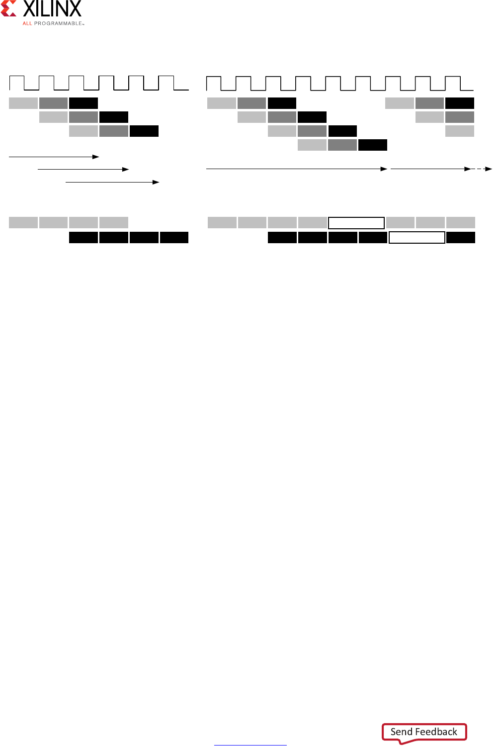
High-Level Synthesis 142
UG902 (v2017.1) April 5, 2017 www.xilinx.com
Chapter 1: High-Level Synthesis
An implication from the difference in behavior is the difference in how inputs and outputs
to the pipeline are processed. As seen the figure above, a pipelined function will
continuously read new inputs and write new outputs. By contrast, because a loop must first
finish all operations in the loop before starting the next loop, a pipelined loop causes a
“bubble” in the data stream: a point when no new inputs are read as the loop completes the
execution of the final iterations, and a point when no new outputs are written as the loop
starts new loop iterations.
Rewinding Pipelined Loops for Performance
Loops which are the top-level loop in a function or are used in a region where the
DATAFLOW optimization is used can be made to continuously execute using the PIPELINE
directive with the rewind option.
The following figure shows the operation when the rewind option is used when pipelining
a loop. At the end of the loop iteration count, the loop immediately starts to re-execute.
X-Ref Target - Figure 1-52
Figure 1-52: Function and Loop Pipelining Behavior
([HFXWH)XQFWLRQ
3LSHOLQHG)XQFWLRQ 3LSHOLQHG/RRS
([HFXWH1H[W
([HFXWH1H[W ([HFXWH/RRS ([HFXWH1H[W
/RRS
3LSHOLQHG)XQFWLRQ,2$FFHVVHV 3LSHOLQHG/RRS,2$FFHVVHV
;
5' &03 :5
5' &03 :5
5' &03 :5
5' &03 :5
5' &03 :5
5' &03 :5
5' &03 :5
5' &03
5'
5' 5' 5' 5'1
:5 :5 :5 :51
5' 5' 5' 5'1
:5 :5 :5 :51 :5
5' 5' 5'
%XEEOH
%XEEOH
5'1 &03 :51
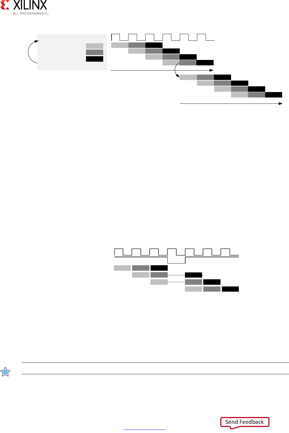
High-Level Synthesis 143
UG902 (v2017.1) April 5, 2017 www.xilinx.com
Chapter 1: High-Level Synthesis
If the loop is the top-level loop in a function, the C code before the loop cannot perform
any operations on the data. The result of the function must be the same if the function is
executed again or if the loop immediately re-executes.
If the loop is used in a region with the DATAFLOW optimization, Vivado HLS automatically
implements the loop as if it is in a function hierarchy.
Flushing Pipelines
Pipelines continue to execute as long as data is available at the input of the pipeline. If there
is no data available to process, the pipeline will stall. This is shown in the following figure,
where the input data valid signal goes low to indicate there is no more data. Once there is
new data available to process, the pipeline will continue operation.
In some cases, it is desirable to have a pipeline that can be “emptied” or “flushed”. The
flush option is provided to perform this. When a pipeline is “flushed” the pipeline stops
reading new inputs when none are available (as determined by a data valid signal at the
start of the pipeline) but continues processing, shutting down each successive pipeline
stage, until the final input has been processed through to the output of the pipeline.
IMPORTANT: The pipeline flush feature is only supported for pipelined functions.
X-Ref Target - Figure 1-53
Figure 1-53: Loop Pipelining with Rewind Option
X-Ref Target - Figure 1-54
Figure 1-54: Loop Pipelining with Stall
5' &03 :5
5' &03 :5
5' &03 :5
([HFXWH/RRS
5'1 &03 :51
5' &03 :5
5' &03 :5
5' &03 :5
5'1 &03 :51
([HFXWH1H[W/RRS
Loop:for(i=1;i<N;i++){
op_Read;
op_Compute;
op_Write;
}
5'
&03
:5
;
5' &03 :5
,QSXW'DWD9DOLG
5' &03
5'
5'1 &03 :51
&03
:5
:5
;

High-Level Synthesis 144
UG902 (v2017.1) April 5, 2017 www.xilinx.com
Chapter 1: High-Level Synthesis
Automatic Loop Pipelining
The config_compile configuration enables loops to be pipelined automatically based on
the iteration count. This configuration is accessed through the menu Solution > Solution
Settings > General > Add > config_compile.
The pipeline_loops option set the iteration limit. All loops with an iteration count below
this limit are automatically pipelined. The default is 0: no automatic loop pipelining is
performed.
Given the following example code:
for (y = 0; y < 480; y++) {
for (x = 0; x < 640; x++) {
for (i = 0; i < 5; i++) {
// do something 5 times
…
}
}
}
If the pipeline_loops option is set to 10 (a value above 5 but below 5*640), the
following pipelining is performed automatically:
for (y = 0; y < 480; y++) {
for (x = 0; x < 640; x++) {
#pragma HLS PIPELINE II=1
for (i = 0; i < 5; i++) {
// This loop will be automatically unrolled
// do something 5 times in parallel
…
}
}
}
If there are loops in the design that you do not want to use automatic pipelining, apply the
PIPELINE directive with the off option to that loop. The off option prevents automatic
loop pipelining.
IMPORTANT: Vivado HLS applies the config_compile pipeline_loops option after performing
all user-specified directives. For example, if Vivado HLS applies a user-specified UNROLL directive to a
loop, the loop is first unrolled, and automatic loop pipelining cannot be applied.
Addressing Failure to Pipeline
When a task is pipelined, all loops in the hierarchy are automatically unrolled. This is a
requirement for pipelining to proceed. If a loop has variables bounds it cannot be unrolled.
This will prevent the task from being pipelined. Refer to Variable Loop Bounds in Chapter 3
for techniques to remove such loops from the design.

High-Level Synthesis 145
UG902 (v2017.1) April 5, 2017 www.xilinx.com
Chapter 1: High-Level Synthesis
Partitioning Arrays to Improve Pipelining
A common issue when pipelining tasks is the following message:
INFO: [SCHED 204-61] Pipelining loop 'SUM_LOOP'.
WARNING: [SCHED 204-69] Unable to schedule 'load' operation ('mem_load_2',
bottleneck.c:62) on array 'mem' due to limited memory ports.
WARNING: [SCHED 204-69] The resource limit of core:RAM:mem:p0 is 1, current
assignments:
WARNING: [SCHED 204-69] 'load' operation ('mem_load', bottleneck.c:62) on array
'mem',
WARNING: [SCHED 204-69] The resource limit of core:RAM:mem:p1 is 1, current
assignments:
WARNING: [SCHED 204-69] 'load' operation ('mem_load_1', bottleneck.c:62) on array
'mem',
INFO: [SCHED 204-61] Pipelining result: Target II: 1, Final II: 2, Depth: 3.
In this example, Vivado HLS states it cannot reach the specified initiation interval (II) of 1
because it cannot schedule a load (read) operation onto the memory because of limited
memory ports. The above message notes that the resource limit for "core:RAM:mem:p0
is 1" which is used by the operation on line 64. The 2nd port of the BlockRAM also only
has 1 resource which is also used. It reports a final II of 2 instead of the desired 1.
This issue is typically caused by arrays. Arrays are implemented as block RAM which only
has a maximum of two data ports. This can limit the throughput of a read/write (or
load/store) intensive algorithm. The bandwidth can be improved by splitting the array (a
single block RAM resource) into multiple smaller arrays (multiple block RAMs), effectively
increasing the number of ports.
Arrays are partitioned using the ARRAY_PARTITION directive. Vivado HLS provides three
types of array partitioning, as shown in the following figure. The three styles of partitioning
are:
•block: The original array is split into equally sized blocks of consecutive elements of
the original array.
•cyclic: The original array is split into equally sized blocks interleaving the elements of
the original array.
•complete: The default operation is to split the array into its individual elements. This
corresponds to resolving a memory into registers.
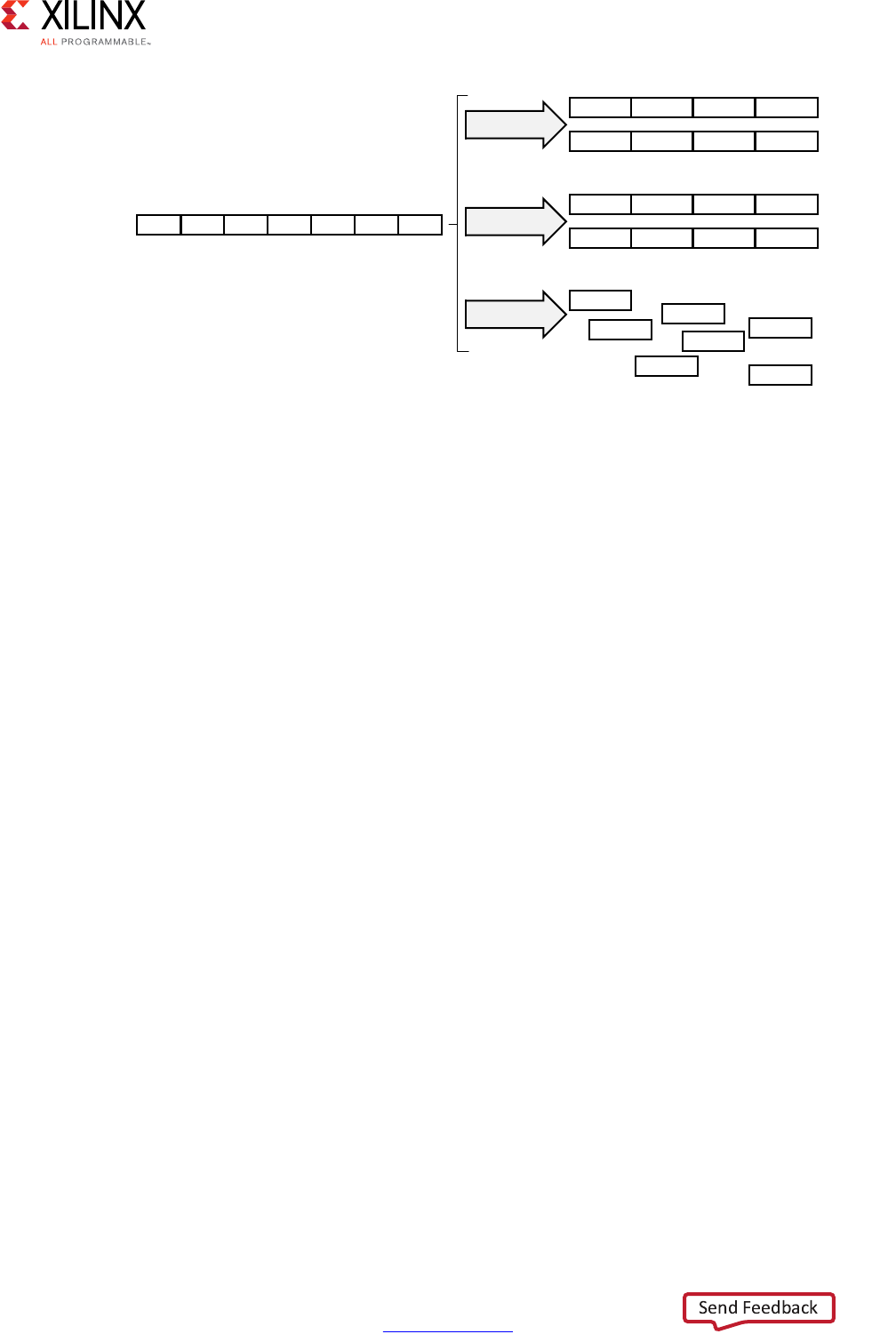
High-Level Synthesis 146
UG902 (v2017.1) April 5, 2017 www.xilinx.com
Chapter 1: High-Level Synthesis
For block and cyclic partitioning the factor option specifies the number of arrays that are
created. In the preceding figure, a factor of 2 is used, that is, the array is divided into two
smaller arrays. If the number of elements in the array is not an integer multiple of the factor,
the final array has fewer elements.
When partitioning multi-dimensional arrays, the dimension option is used to specify
which dimension is partitioned. The following figure shows how the dimension option is
used to partition the following example code:
void foo (...) {
int my_array[10][6][4];
...
}
The examples in the figure demonstrate how partitioning dimension 3 results in 4 separate
arrays and partitioning dimension 1 results in 10 separate arrays. If zero is specified as the
dimension, all dimensions are partitioned.
X-Ref Target - Figure 1-55
Figure 1-55: Array Partitioning
1 1 1
1
1 1 1
1
1 1
1
1
1
EORFN
F\FOLF
FRPSOHWH
;

High-Level Synthesis 147
UG902 (v2017.1) April 5, 2017 www.xilinx.com
Chapter 1: High-Level Synthesis
Automatic Array Partitioning
The config_array_partition configuration determines how arrays are automatically
partitioned based on the number of elements. This configuration is accessed through the
menu Solution > Solution Settings > General > Add > config_array_partition.
The partition thresholds can be adjusted and partitioning can be fully automated with the
throughput_driven option. When the throughput_driven option is selected Vivado
HLS automatically partitions arrays to achieve the specified throughput.
Dependencies with Vivado HLS
Vivado HLS constructs a hardware datapath that corresponds to the C source code.
When there is no pipeline directive, the execution is sequential so there is no dependencies
to take into account but when the design has been pipelined, the tool needs to deal with
the same dependencies as found in processor architectures for the hardware that Vivado
HLS generates.
The data dependencies or memory dependencies are when a read or a write occurs after a
previous read or write.
• A read-after-write (RAW) is a true dependency when an instruction (and data it
reads/uses) depends on the result of a previous operation.
°I1: t = a * b;
°I2: c = t + 1;
The read in I2 depends on the write of t in I1. If the instructions are reordered, it uses the
previous value of t.
X-Ref Target - Figure 1-56
Figure 1-56: Partitioning Array Dimensions
my_array_0[10][6]
my_array_1[10][6]
my_array_2[10][6]
my_array_3[10][6]
my_array_0[6][4]
my_array_1[6][4]
my_array_2[6][4]
my_array_3[6][4]
my_array_4[6][4]
my_array_5[6][4]
my_array_6[6][4]
my_array_7[6][4]
my_array_8[6][4]
my_array_9[6][4]
my_array[10][6][4] partition dimension 3
my_array[10][6][4] partition dimension 1
my_array[10][6][4] partition dimension 0 10x6x4 = 240 registers
;

High-Level Synthesis 148
UG902 (v2017.1) April 5, 2017 www.xilinx.com
Chapter 1: High-Level Synthesis
• A write-after-read (WAR) is an anti-dependence when an instruction cannot update a
register or memory (by a write) before a previous instruction has read the data.
°I1: b = t + a;
°I2: t = 3;
The write in I2 cannot execute before I1 otherwise the result of b is invalid: this is a
write-after-read dependence.
• A write-after-write (WAW) is a dependence when a register or memory must be written
in specific order otherwise other instructions might be corrupted.
°I1: t = a * b;
°I2: c = t + 1;
°I3: t = 1;
The write in I3 must happen after the write in I1. Otherwise, the I2 result is incorrect.
• A read-after-read has no dependency as instructions can be freely reordered.
For example, when a pipeline is generated, the tool needs to take care that a register or
memory location read at a later stage has not been modified by a previous write. This is a
true dependency or read-after-write (RAW) dependency. A specific example is:
int top(int a, int b) {
int t,c;
I1: t = a * b;
I2: c = t + 1;
return c;
}
Instruction I2 cannot start before instruction I1 has completed because there is a
dependency on variable t. In hardware, if the multiplication takes 3 clock cycles, then I2 is
delayed for that amount of time. It would be incorrect for VHLS to generate hardware that
takes the previous value of t. If this datapath is pipelined, then the latency would be 3 but
the initiation interval II would be 1 as this is a strict feed-forward datapath.
Memory dependencies arise when the example applies to an array and not just variables.
int top(int a) {
int r=1,rnext,m,i,out;
static int mem[256];
L1: for(i=0;i<=254;i++) {
#pragma HLS PIPELINE II=1
I1: m = r * a , mem[i+1]=m; // line 7
I2: rnext = mem[i], r = rnext; // line 8
}
return r;
}
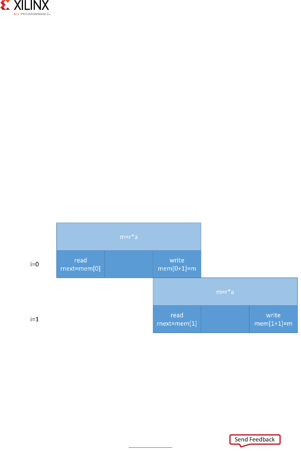
High-Level Synthesis 149
UG902 (v2017.1) April 5, 2017 www.xilinx.com
Chapter 1: High-Level Synthesis
In the above example, scheduling of loop L1 leads to a scheduling warning message:
WARNING: [SCHED 204-68] Unable to enforce a carried dependency constraint (II = 1,
distance = 1)
between 'store' operation (top.cpp:7) of variable 'm', top.cpp:7 on array 'mem' and
'load' operation ('rnext', top.cpp:8) on array 'mem'.
INFO: [SCHED 204-61] Pipelining result: Target II: 1, Final II: 2, Depth: 3.
There are no issues within the same iteration of the loop as you write an index and read
another one. The two instructions could execute at the same time, concurrently. However,
observe the read and writes over a few iterations:
// Iteration for i=0
I1: m = r * a , mem[1]=m; // line 7
I2: rnext = mem[0], r = rnext; // line 8
// Iteration for i=1
I1: m = r * a , mem[2]=m; // line 7
I2: rnext = mem[1], r = rnext; // line 8
// Iteration for i=2
I1: m = r * a , mem[3]=m; // line 7
I2: rnext = mem[2], r = rnext; // line 8
When considering 2 successive iterations, the multiplication result m (with a latency = 2)
from I1 is written to a location that is read by I2 of the next iteration of the loop into
rnext. In this situation, there is a RAW true dependence as the next loop iteration cannot
start reading mem[i] before the previous computation's write completes.
Note that if the clock frequency is increased, then the multiplier needs more pipeline stages
and increased latency. This will force II to increase as well.
X-Ref Target - Figure 1-57
Figure 1-57: Dependency Example

High-Level Synthesis 150
UG902 (v2017.1) April 5, 2017 www.xilinx.com
Chapter 1: High-Level Synthesis
int top(int a) {
int r,m,i;
static int mem[256];
L1: for(i=0;i<=254;i++) {
#pragma HLS PIPELINE II=1
I1: r = mem[i]; // line 7
I2: m = r * a , mem[i+1]=m; // line 8
}
return r;
}
In the above example, the operations are swapped, changing the functionality. The
scheduling warning is:
INFO: [SCHED 204-61] Pipelining loop 'L1'.
WARNING: [SCHED 204-68] Unable to enforce a carried dependency constraint (II = 1,
distance = 1)
between 'store' operation (top.cpp:8) of variable 'm', top.cpp:8 on array 'mem'
and 'load' operation ('r', top.cpp:7) on array 'mem'.
WARNING: [SCHED 204-68] Unable to enforce a carried dependency constraint (II = 2,
distance = 1)
between 'store' operation (top.cpp:8) of variable 'm', top.cpp:8 on array 'mem'
and 'load' operation ('r', top.cpp:7) on array 'mem'.
WARNING: [SCHED 204-68] Unable to enforce a carried dependency constraint (II = 3,
distance = 1)
between 'store' operation (top.cpp:8) of variable 'm', top.cpp:8 on array 'mem'
and 'load' operation ('r', top.cpp:7) on array 'mem'.
INFO: [SCHED 204-61] Pipelining result: Target II: 1, Final II: 4, Depth: 4.
However, observe the continued read and writes over a few iterations:
Iteration with i=0
I1: r = mem[0]; // line 7
I2: m = r * a , mem[1]=m; // line 8
Iteration with i=1
I1: r = mem[1]; // line 7
I2: m = r * a , mem[2]=m; // line 8
Iteration with i=2
I1: r = mem[2]; // line 7
I2: m = r * a , mem[3]=m; // line 8
The longer II is needed because the WAR dependence is via reading r from mem[i],
performing the multiplication, and writing to mem[i+1].
Removing False Dependencies to Improve Loop Pipelining
Loop pipelining can be prevented by loop carry dependencies. Under certain complex
scenarios automatic dependence analysis can be too conservative and fail to filter out false
dependencies.
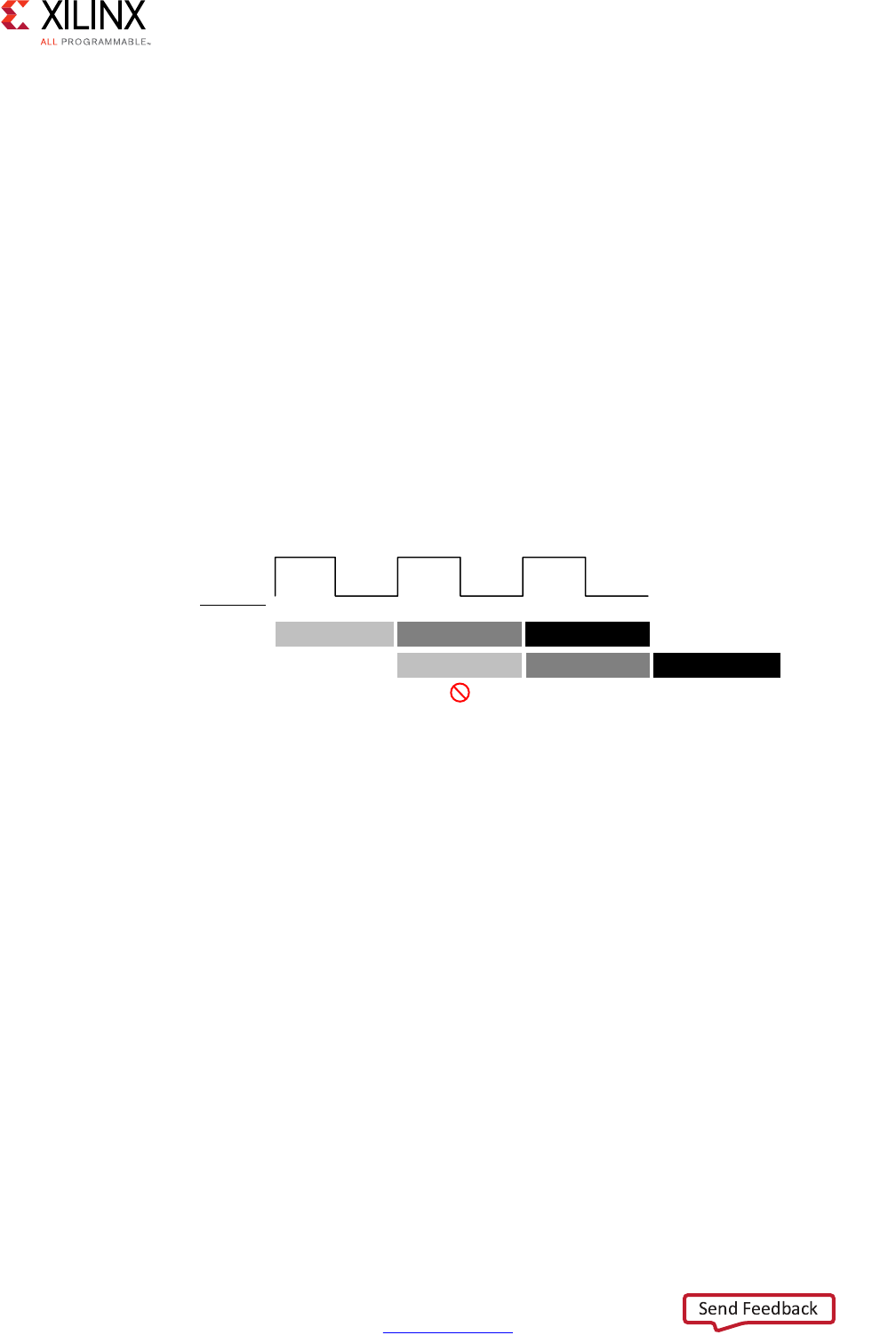
High-Level Synthesis 151
UG902 (v2017.1) April 5, 2017 www.xilinx.com
Chapter 1: High-Level Synthesis
In this example, the Vivado HLS does not have any knowledge about the value of cols and
conservatively assumes that there is always a dependence between the write to
buff_A[1][col]and the read from buff_A[1][col].
void foo(int rows, int cols, ...)
for (row = 0; row < rows + 1; row++) {
for (col = 0; col < cols + 1; col++) {
#pragma HLS PIPELINE II=1
if (col < cols) {
buff_A[2][col] = buff_A[1][col]; // read from buff_A[1][col]
buff_A[1][col] = buff_A[0][col]; // write to buff_A[1][col]
buff_B[1][col] = buff_B[0][col];
temp = buff_A[0][col];
}
The issue is highlighted in the following figure. If cols=0, the next iteration of the rows
loop starts immediately, and the read from buff_A[0][cols] cannot happen at the same
time as the write.
In an algorithm such as this, it is unlikely cols will ever be zero but Vivado HLS cannot
make assumptions about data dependencies. To overcome this deficiency, you can use the
DEPENDENCE directive to provide Vivado HLS with additional information about the
dependencies. In this case, state there is no dependence between loop iterations (in this
case, for both buff_A and buff_B).
void foo(int rows, int cols, ...)
for (row = 0; row < rows + 1; row++) {
for (col = 0; col < cols + 1; col++) {
#pragma HLS PIPELINE II=1
#pragma HLS dependence variable=buff_A inter false
#pragma HLS dependence variable=buff_B inter false
if (col < cols) {
buff_A[2][col] = buff_A[1][col]; // read from buff_A[1][col]
buff_A[1][col] = buff_A[0][col]; // write to buff_A[1][col]
buff_B[1][col] = buff_B[0][col];
temp = buff_A[0][col];
}
Note: Specifying a false dependency, when in fact the dependency is not false, can result in
incorrect hardware. Be sure dependencies are correct (true or false) before specifying them.
X-Ref Target - Figure 1-58
Figure 1-58: Partitioning Array Dimensions
5RZ&RO
5HDG
%XII>@>FRO@DFFHVVHVLIFROV
:ULWH (WF
:ULWH5HDG (WF
;
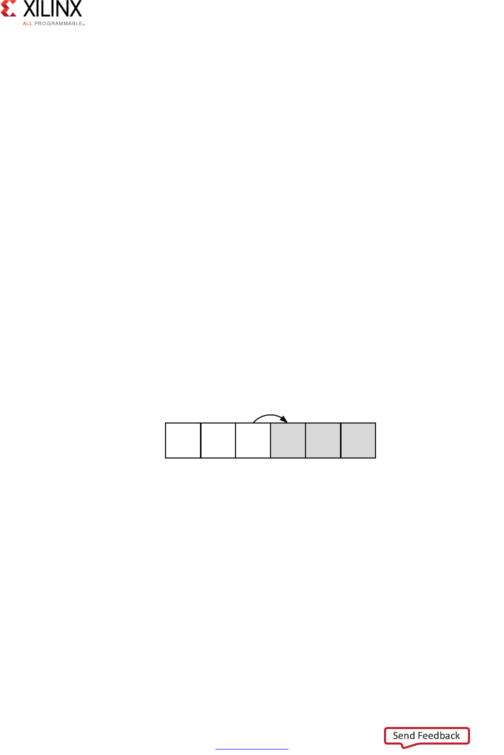
High-Level Synthesis 152
UG902 (v2017.1) April 5, 2017 www.xilinx.com
Chapter 1: High-Level Synthesis
When specifying dependencies there are two main types:
•Inter: Specifies the dependency is between different iterations of the same loop.
If this is specified as false it allows Vivado HLS to perform operations in parallel if the
pipelined or loop is unrolled or partially unrolled and prevents such concurrent
operation when specified as true.
•Intra: Specifies dependence within the same iteration of a loop, for example an array
being accessed at the start and end of the same iteration.
When intra dependencies are specified as false Vivado HLS may move operations freely
within the loop, increasing their mobility and potentially improving performance or
area. When the dependency is specified as true, the operations must be performed in
the order specified.
Data dependencies are a much harder issues to resolve and often require changes to the
source code. A scalar data dependency could look like the following:
while (a != b) {
if (a > b) a -= b;
else b -= a;
}
The next iteration of this loop cannot start until the current iteration has calculated the
updated the values of a and b, as shown in the following figure.
If the result of the previous loop iteration must be available before the current iteration can
begin, loop pipelining is not possible. If Vivado HLS cannot pipeline with the specified
initiation interval it increases the initiation internal. If it cannot pipeline at all, as shown by
the above example, it halts pipelining and proceeds to output a non-pipelined design.
Optimal Loop Unrolling to Improve Pipelining
By default loops are kept rolled in Vivado HLS. That is to say that the loops are treated as a
single entity: all operations in the loop are implemented using the same hardware resources
for iteration of the loop.
X-Ref Target - Figure 1-59
Figure 1-59: Scalar Dependency
! !
;
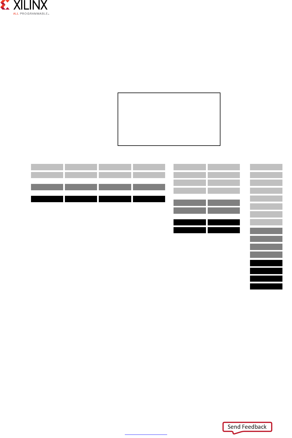
High-Level Synthesis 153
UG902 (v2017.1) April 5, 2017 www.xilinx.com
Chapter 1: High-Level Synthesis
Vivado HLS provides the ability to unroll or partially unroll for-loops using the UNROLL
directive.
The following figure shows both the powerful advantages of loop unrolling and the
implications that must be considered when unrolling loops. This example assumes the
arrays a[i], b[i] and c[i] are mapped to block RAMs. This example shows how easy
it is to create many different implementations by the simple application of loop unrolling.
•Rolled Loop: When the loop is rolled, each iteration is performed in a separate clock
cycle. This implementation takes four clock cycles, only requires one multiplier and
each block RAM can be a single-port block RAM.
•Partially Unrolled Loop: In this example, the loop is partially unrolled by a factor of 2.
This implementation required two multipliers and dual-port RAMs to support two reads
or writes to each RAM in the same clock cycle. This implementation does however only
take 2 clock cycles to complete: half the initiation interval and half the latency of the
rolled loop version.
X-Ref Target - Figure 1-60
Figure 1-60: Loop Unrolling Details
void top(...) {
...
for_mult:for (i=3;i>0;i--) {
a[i] = b[i] * c[i];
}
...
}
5HDGE>@
:ULWHD>@
5ROOHG/RRS
5HDGF>@
5HDGE>@
:ULWHD>@
5HDGF>@
5HDGE>@
:ULWHD>@
5HDGF>@
5HDGE>@
:ULWHD>@
5HDGF>@
5HDGE>@
:ULWHD>@
5HDGF>@
5HDGE>@
:ULWHD>@
5HDGF>@
3DUWLDOO\8QUROOHG/RRS
5HDGE>@
5HDGF>@
5HDGE>@
5HDGF>@
:ULWHD>@ :ULWHD>@
5HDGE>@
:ULWHD>@
5HDGF>@
8QUROOHG/RRS
5HDGE>@
5HDGF>@
:ULWHD>@
5HDGE>@
5HDGF>@
5HDGE>@
5HDGF>@
:ULWHD>@
:ULWHD>@
;

High-Level Synthesis 154
UG902 (v2017.1) April 5, 2017 www.xilinx.com
Chapter 1: High-Level Synthesis
•Unrolled loop: In the fully unrolled version all loop operation can be performed in a
single clock cycle. This implementation however requires four multipliers. More
importantly, this implementation requires the ability to perform 4 reads and 4 write
operations in the same clock cycle. Because a block RAM only has a maximum of two
ports, this implementation requires the arrays be partitioned.
To perform loop unrolling, you can apply the UNROLL directives to individual loops in the
design. Alternatively, you can apply the UNROLL directive to a function, which unrolls all
loops within the scope of the function.
If a loop is completely unrolled, all operations will be performed in parallel: if data
dependencies allow. If operations in one iteration of the loop require the result from a
previous iteration, they cannot execute in parallel but will execute as soon as the data is
available. A completely unrolled loop will mean multiple copies of the logic in the loop
body.
The following example code demonstrates how loop unrolling can be used to create an
optimal design. In this example, the data is stored in the arrays as interleaved channels. If
the loop is pipelined with II=1 each channel is only read and written every 8th block cycle.
// Array Order : 0 1 2 3 4 5 6 7 8 9 10 etc. 16 etc...
// Sample Order: A0 B0 C0 D0 E0 F0 G0 H0 A1 B1 C2 etc. A2 etc...
// Output Order: A0 B0 C0 D0 E0 F0 G0 H0 A0+A1 B0+B1 C0+C2 etc. A0+A1+A2 etc...
#define CHANNELS 8
#define SAMPLES 400
#define N CHANNELS * SAMPLES
void foo (dout_t d_o[N], din_t d_i[N]) {
int i, rem;
// Store accumulated data
static dacc_t acc[CHANNELS];
// Accumulate each channel
For_Loop: for (i=0;i<N;i++) {
rem=i%CHANNELS;
acc[rem] = acc[rem] + d_i[i];
d_o[i] = acc[rem];
}
}
Partially unrolling the loop by a factor of 8 will allow each of the channels (every 8th
sample) to be processed in parallel (if the input and output arrays are also partitioned in a
cyclic manner to allow multiple accesses per clock cycle). If the loop is also pipelined with
the rewind option, this design will continuously process all 8 channels in parallel.

High-Level Synthesis 155
UG902 (v2017.1) April 5, 2017 www.xilinx.com
Chapter 1: High-Level Synthesis
void foo (dout_t d_o[N], din_t d_i[N]) {
#pragma HLS ARRAY_PARTITION variable=d_i cyclic factor=8 dim=1 partition
#pragma HLS ARRAY_PARTITION variable=d_o cyclic factor=8 dim=1 partition
int i, rem;
// Store accumulated data
static dacc_t acc[CHANNELS];
// Accumulate each channel
For_Loop: for (i=0;i<N;i++) {
#pragma HLS PIPELINE rewind
#pragma HLS UNROLL factor=8
rem=i%CHANNELS;
acc[rem] = acc[rem] + d_i[i];
d_o[i] = acc[rem];
}
}
Partial loop unrolling does not require the unroll factor to be an integer multiple of the
maximum iteration count. Vivado HLS adds an exit checks to ensure partially unrolled loops
are functionally identical to the original loop. For example, given the following code:
for(int i = 0; i < N; i++) {
a[i] = b[i] + c[i];
}
Loop unrolling by a factor of 2 effectively transforms the code to look like the following
example where the break construct is used to ensure the functionality remains the same:
for(int i = 0; i < N; i += 2) {
a[i] = b[i] + c[i];
if (i+1 >= N) break;
a[i+1] = b[i+1] + c[i+1];
}
Because N is a variable, Vivado HLS may not be able to determine its maximum value (it
could be driven from an input port). If you know the unrolling factor, 2 in this case, is an
integer factor of the maximum iteration count N, the skip_exit_check option removes
the exit check and associated logic. The effect of unrolling can now be represented as:
for(int i = 0; i < N; i += 2) {
a[i] = b[i] + c[i];
a[i+1] = b[i+1] + c[i+1];
}
This helps minimize the area and simplify the control logic.
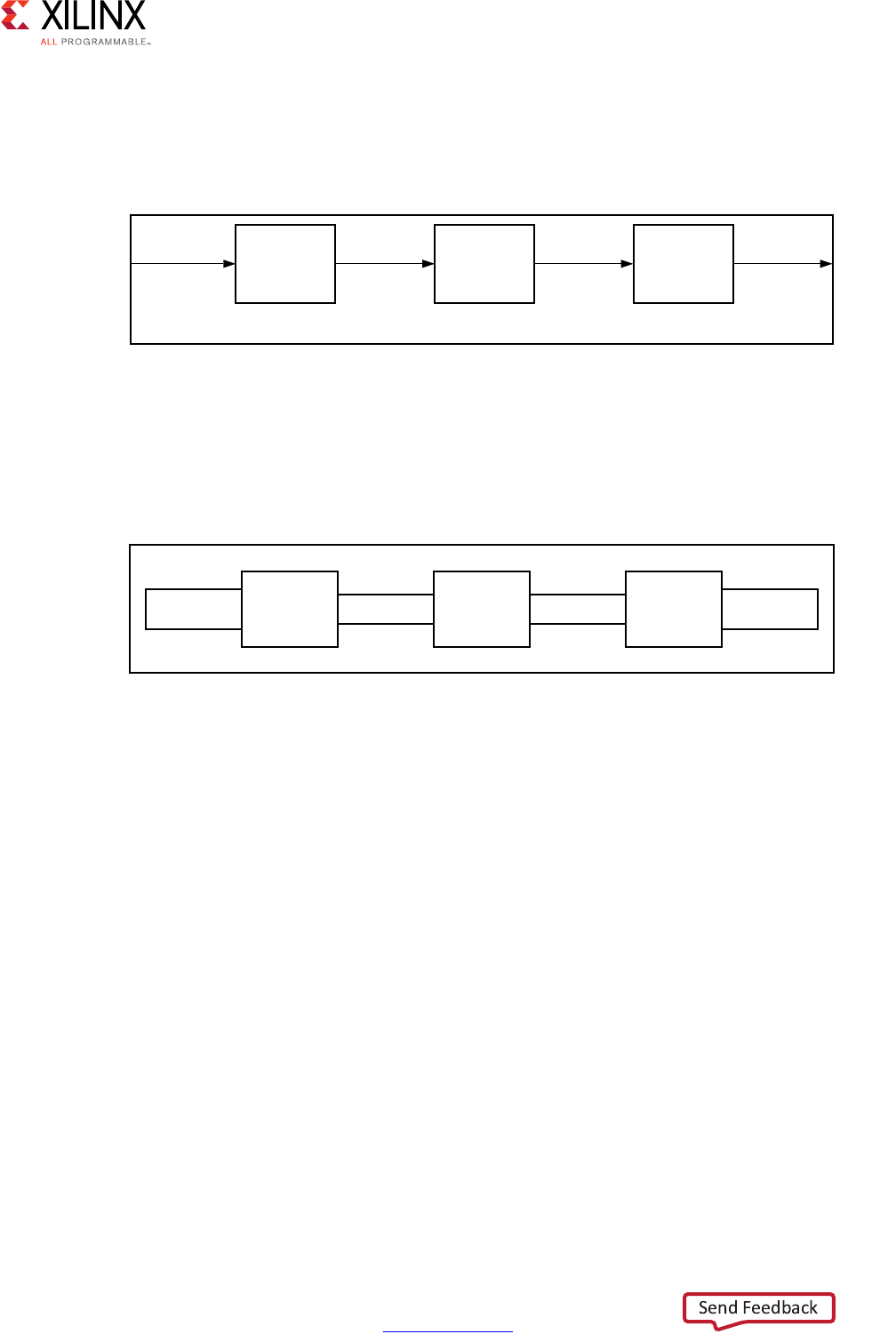
High-Level Synthesis 156
UG902 (v2017.1) April 5, 2017 www.xilinx.com
Chapter 1: High-Level Synthesis
Task Level Pipelining: Dataflow Optimization
The DATAFLOW optimization starts with a series of sequential tasks (functions, loops, or
both) as shown in the following figure.
Using this series of sequential tasks, DATAFLOW optimization creates a parallel process
architecture as shown in the following figure. Dataflow optimization is a powerful method
for improving design throughput.
The channels shown in the preceding figure ensure a task is not required to wait until the
previous task has completed all operations before it can begin. The following figure shows
how DATAFLOW optimization allows the execution of tasks to overlap, increasing the overall
throughput of the design and reducing latency.
In the example without dataflow pipelining (A) in the following figure, the implementation
requires 8 cycles before a new input can be processed by func_A and 8 cycles before an
output is written by func_C.
In the example with dataflow pipelining (B) in the following figure, func_A can begin
processing a new input every 3 clock cycles (lower initiation interval) and it now only
requires 5 clocks to output a final value (shorter latency).
X-Ref Target - Figure 1-61
Figure 1-61: Sequential Functional Description
X-Ref Target - Figure 1-62
Figure 1-62: Parallel Process Architecture
IXQFWLRQB IXQFWLRQB1
723
LQ LQ RXW WPS WPS RXW
LQ RXW LQ RXW
;
;
723
,QWHUIDFH 3URFHVVB &KDQQHO &KDQQHO 3URFHVVB1 ,QWHUIDFH
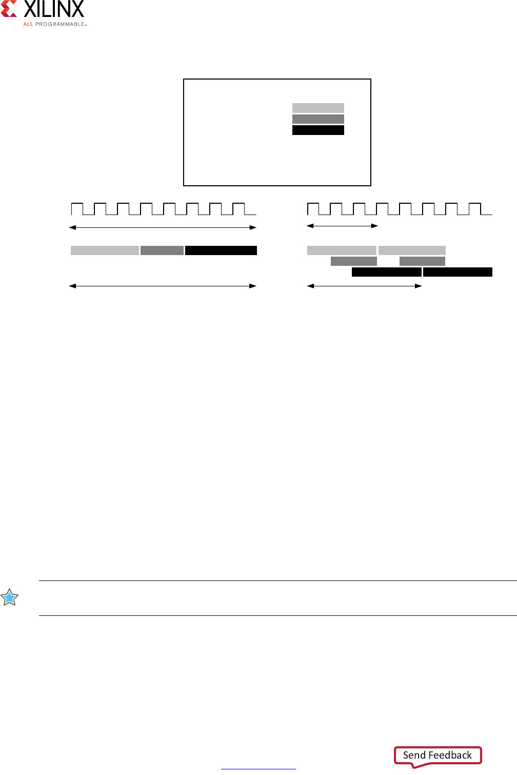
High-Level Synthesis 157
UG902 (v2017.1) April 5, 2017 www.xilinx.com
Chapter 1: High-Level Synthesis
Dataflow Optimization Limitations
For the DATAFLOW optimization to work, the data must flow through the design from one
task to the next. The following coding styles prevent Vivado HLS from performing the
DATAFLOW optimization:
• Single-producer-consumer violations
• Bypassing tasks
• Feedback between tasks
• Conditional execution of tasks
• Loops with multiple exit conditions
IMPORTANT: If any of these coding styles are present, Vivado HLS issues a message and does not
perform DATAFLOW optimization.
Note: The dataflow viewer in the Analysis Perspective may be used to view the structure when the
DATAFLOW directive is applied. Refer to Analysis Perspective for more details.
X-Ref Target - Figure 1-63
Figure 1-63: Dataflow Optimization
void top (a,b,c,d) {
...
func_A(a,b,i1);
func_B(c,i1,i2);
func_C(i2,d)
return d;
}
IXQFB$
IXQFB%
IXQFB&
F\FOHV
IXQFB$ IXQFB% IXQFB&
F\FOHV
F\FOHV
IXQFB$
IXQFB%
IXQFB&
IXQFB$
IXQFB%
IXQFB&
F\FOHV
$:LWKRXW'DWDIORZ3LSHOLQLQJ %:LWK'DWDIORZ3LSHOLQLQJ
;

High-Level Synthesis 158
UG902 (v2017.1) April 5, 2017 www.xilinx.com
Chapter 1: High-Level Synthesis
For Vivado HLS to perform the DATAFLOW optimization, all elements passed between tasks
must follow a single-producer-consumer model. Each variable must be driven from a single
task and only be consumed by a single task. In the following code example, temp1 fans out
and is consumed by both Loop2 and Loop3. This violates the single-producer-consumer
model.
void foo(int data_in[N], int scale, int data_out1[N], int data_out2[N]) {
int temp1[N];
Loop1: for(int i = 0; i < N; i++) {
temp1[i] = data_in[i] * scale;
}
Loop2: for(int j = 0; j < N; j++) {
data_out1[j] = temp1[j] * 123;
}
Loop3: for(int k = 0; k < N; k++) {
data_out2[k] = temp1[k] * 456;
}
}
A modified version of this code uses function Split to create a single-producer-consumer
design. In this case, data flows from Loop1 to function Split and then to Loop2 and
Loop3. The data now flows between all four tasks, and Vivado HLS can perform the
DATAFLOW optimization.
void Split (in[N], out1[N], out2[N]) {
// Duplicated data
L1:for(int i=1;i<N;i++) {
out1[i] = in[i];
out2[i] = in[i];
}
}
void foo(int data_in[N], int scale, int data_out1[N], int data_out2[N]) {
int temp1[N], temp2[N]. temp3[N];
Loop1: for(int i = 0; i < N; i++) {
temp1[i] = data_in[i] * scale;
}
Split(temp1, temp2, temp3);
Loop2: for(int j = 0; j < N; j++) {
data_out1[j] = temp2[j] * 123;
}
Loop3: for(int k = 0; k < N; k++) {
data_out2[k] = temp3[k] * 456;
}
}

High-Level Synthesis 159
UG902 (v2017.1) April 5, 2017 www.xilinx.com
Chapter 1: High-Level Synthesis
In addition, data must flow from one task into the next task. If you bypass tasks, this inhibits
the DATAFLOW optimization. In this example, Loop1 generates the values for temp1 and
temp2. However, the next task, Loop2, only uses the value of temp1. The value of temp2 is
not consumed until after Loop2. Therefore, temp2 bypasses the next task in the sequence,
which prevents Vivado HLS from performing the DATFLOW optimization.
void foo(int data_in[N], int scale, int data_out1[N], int data_out2[N]) {
int temp1[N], temp2[N]. temp3[N];
Loop1: for(int i = 0; i < N; i++) {
temp1[i] = data_in[i] * scale;
temp2[i] = data_in[i] >> scale;
}
Loop2: for(int j = 0; j < N; j++) {
temp3[j] = temp1[j] + 123;
}
Loop3: for(int k = 0; k < N; k++) {
data_out[k] = temp2[k] + temp3[k];
}
}
Because the loop iteration limits are all the same in this example, you can modify the code
so that Loop2 consumes temp2 and produces temp4 as follows. This ensures that the data
flows from one task to the next.
void foo(int data_in[N], int scale, int data_out1[N], int data_out2[N]) {
int temp1[N], temp2[N]. temp3[N], temp4[N];
Loop1: for(int i = 0; i < N; i++) {
temp1[i] = data_in[i] * scale;
temp2[i] = data_in[i] >> scale;
}
Loop2: for(int j = 0; j < N; j++) {
temp3[j] = temp1[j] + 123;
temp4[j] = temp2[j];
}
Loop3: for(int k = 0; k < N; k++) {
data_out[k] = temp4[k] + temp3[k];
}
}
Feedback occurs when the output from a task is consumed by a previous task in the
DATAFLOW region. Feedback between tasks is not permitted in a DATAFLOW region. When
Vivado HLS detects feedback, it issues a warning and does not perform the DATAFLOW
optimization.

High-Level Synthesis 160
UG902 (v2017.1) April 5, 2017 www.xilinx.com
Chapter 1: High-Level Synthesis
The DATAFLOW optimization does not optimize tasks that are conditionally executed. The
following example highlights this limitation. In this example, the conditional execution of
Loop1 and Loop2 prevents Vivado HLS from optimizing the data flow between these loops,
because the data does not flow from one loop into the next.
void foo(int data_in1[N], int data_out[N], int sel) {
int temp1[N], temp2[N];
if (sel) {
Loop1: for(int i = 0; i < N; i++) {
temp1[i] = data_in[i] * 123;
temp2[i] = data_in[i];
}
} else {
Loop2: for(int j = 0; j < N; j++) {
temp1[j] = data_in[j] * 321;
temp2[j] = data_in[j];
}
}
Loop3: for(int k = 0; k < N; k++) {
data_out[k] = temp1[k] * temp2[k];
}
}
To ensure each loop is executed in all cases, you must transform the code as shown in the
following example. In this example, the conditional statement is moved into the first loop.
Both loops are always executed, and data always flows from one loop to the next.
void foo(int data_in[N], int data_out[N], int sel) {
int temp1[N], temp2[N];
Loop1: for(int i = 0; i < N; i++) {
if (sel) {
temp1[i] = data_in[i] * 123;
} else {
temp1[i] = data_in[i] * 321;
}
}
Loop2: for(int j = 0; j < N; j++) {
temp2[j] = data_in[j];
}
Loop3: for(int k = 0; k < N; k++) {
data_out[k] = temp1[k] * temp2[k];
}
}
Loops with multiple exit points cannot be used in a DATAFLOW region. In the following
example, Loop2 has three exit conditions:
• An exit defined by the value of N; the loop will exit when k>=N.
• An exit defined by the break statement.
• An exit defined by the continue statement.

High-Level Synthesis 161
UG902 (v2017.1) April 5, 2017 www.xilinx.com
Chapter 1: High-Level Synthesis
#include "ap_cint.h"
#define N 16
typedef int8 din_t;
typedef int15 dout_t;
typedef uint8 dsc_t;
typedef uint1 dsel_t;
void multi_exit(din_t data_in[N], dsc_t scale, dsel_t select, dout_t data_out[N]) {
dout_t temp1[N], temp2[N];
int i,k;
Loop1: for(i = 0; i < N; i++) {
temp1[i] = data_in[i] * scale;
temp2[i] = data_in[i] >> scale;
}
Loop2: for(k = 0; k < N; k++) {
switch(select) {
case 0: data_out[k] = temp1[k] + temp2[k];
case 1: continue;
default: break;
}
}
}
Because a loop’s exit condition is always defined by the loop bounds, the use of break or
continue statements will prohibit the loop being used in a DATAFLOW region.
Finally, the DATAFLOW optimization has no hierarchical implementation. If a sub-function or
loop contains additional tasks that might benefit from the DATAFLOW optimization, you
must apply the DATAFLOW optimization to the loop, the sub-function, or inline the
sub-function.
Configuring Dataflow Memory Channels
Vivado HLS implements channels between the tasks as either ping-pong or FIFO buffers,
depending on the access patterns of the producer and the consumer of the data:
• For scalar, pointer, and reference parameters as well as the function return, Vivado HLS
implements the channel as a FIFO.
Note: For scalar values, the maximum channel size is one, that is, only one value is passed from
one function to another.
• If the parameter (producer or consumer) is an array, Vivado HLS implements the
channel as a ping-pong buffer or a FIFO as follows:
°If Vivado HLS determines the data is accessed in sequential order, Vivado HLS
implements the memory channel as a FIFO channel of depth 1.

High-Level Synthesis 162
UG902 (v2017.1) April 5, 2017 www.xilinx.com
Chapter 1: High-Level Synthesis
°If Vivado HLS is unable to determine that the data is accessed in sequential order or
determines the data is accessed in an arbitrary manner, Vivado HLS implements the
memory channel as a ping-pong buffer, that is, as two block RAMs each defined by
the maximum size of the consumer or producer array.
Note: A ping-pong buffer ensures that the channel always has the capacity to hold all
samples without a loss. However, this might be an overly conservative approach in some
cases. For example, if tasks are pipelined with an interval of 1 and use data in a streaming,
sequential manner but Vivado HLS is unable to automatically determine the sequential data
usage, Vivado HLS implements a ping-pong buffer. In this case, the channel only requires a
single register and not 2 block RAM defined by the size of the array.
To explicitly specify the default channel used between tasks, use the config_dataflow
configuration. This configuration sets the default channel for all channels in a design. To
reduce the size of the memory used in the channel, you can use a FIFO. To explicitly set the
depth or number of elements in the FIFO, use the fifo_depth option.
Specifying the size of the FIFO channels overrides the default safe approach. If any task in
the design can produce or consume samples at a greater rate than the specified size of the
FIFO, the FIFOs might become empty (or full). In this case, the design halts operation,
because it is unable to read (or write). This might result in a stalled, unrecoverable state.
Note: This issue only appears when executing C/RTL co-simulation or when the block is used in a
complete system.
When setting the depth of the FIFOs, it is recommended that you use FIFOs with the default
depth, confirm the design passes C/RTL co-simulation, and then reduce the size of the
FIFOs and confirm C/RTL co-simulation still completes without issues. If RTL co-simulation
fails, the size of the FIFO is likely too small to prevent stalling.
Specifying Arrays as Block RAM or FIFOs
By default all arrays are implemented as block RAM elements, unless complete partitioning
reduces them to individual registers. To use a FIFO instead of a block RAM, the array must
be specified as streaming using the STREAM directive.
The following arrays are automatically specified as streaming:
• If an array on the top-level function interface is set as interface type ap_fifo, axis or
ap_hs it is automatically set as streaming.
• The arrays used in a region where the DATAFLOW optimization is applied are
automatically set to streaming if Vivado HLS determines the data is streaming between
the tasks or if the config_dataflow configuration sets the default memory channel
as FIFO.
All other arrays must be specified as streaming using the STREAM directive if a FIFO is
required for the implementation.

High-Level Synthesis 163
UG902 (v2017.1) April 5, 2017 www.xilinx.com
Chapter 1: High-Level Synthesis
Note: When the STREAM directive is applied to an array, the resulting FIFO implemented in the
hardware contains as many elements as the array. The -depth option can be used to specify the size
of the FIFO.
The STREAM directive is also used to change any arrays in a DATAFLOW region from the
default implementation specified by the config_dataflow configuration.
•If the config_dataflow default_channel is set as ping-pong, any array can be
implemented as a FIFO by applying the STREAM directive to the array.
Note: To use a FIFO implementation, the array must be accessed in a streaming manner.
•If the config_dataflow default_channel is set to FIFO or Vivado HLS has
automatically determined the data in a DATAFLOW region is accessed in a streaming
manner, any array can be implemented as a ping-pong implementation by applying the
STREAM directive to the array with the off option.
When an array in a DATAFLOW region is specified as streaming and implemented as a FIFO,
the FIFO is typically not required to hold the same number of elements as the original array.
The tasks in a DATAFLOW region consume each data sample as soon as it becomes
available. The config_dataflow command with the -fifo_depth option or the
STREAM directive with the -depth can be used to reduce the size of the FIFO to the
minimum number of elements required to ensure flow of data never stalls.
Optimizing for Latency
Using Latency Constraints
Vivado HLS supports the use of a latency constraint on any scope. Latency constraints are
specified using the LATENCY directive.
When a maximum and/or minimum LATENCY constraint is placed on a scope, Vivado HLS
tries to ensure all operations in the function complete within the range of clock cycles
specified.
The latency directive applied to a loop specifies the required latency for a single iteration of
the loop: it specifies the latency for the loop body, as the following examples shows:
Loop_A: for (i=0; i<N; i++) {
#pragma HLS latency max=10
..Loop Body...
}
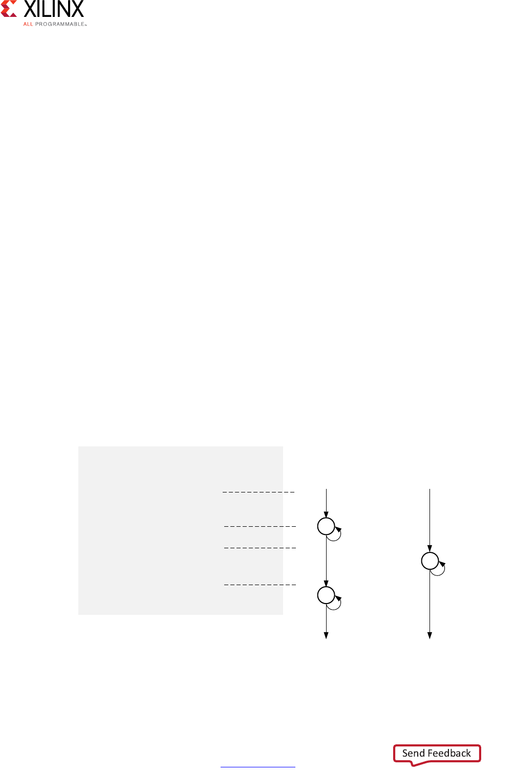
High-Level Synthesis 164
UG902 (v2017.1) April 5, 2017 www.xilinx.com
Chapter 1: High-Level Synthesis
If the intention is to limit the total latency of all loop iterations, the latency directive should
be applied to a region that encompasses the entire loop, as in this example:
Region_All_Loop_A: {
#pragma HLS latency max=10
Loop_A: for (i=0; i<N; i++)
{
..Loop Body...
}
}
In this case, even if the loop is unrolled, the latency directive sets a maximum limit on all
loop operations.
If Vivado HLS cannot meet a maximum latency constraint it relaxes the latency constraint
and tries to achieve the best possible result.
If a minimum latency constraint is set and Vivado HLS can produce a design with a lower
latency than the minimum required it inserts dummy clock cycles to meet the minimum
latency.
Merging Sequential Loops to Reduce Latency
All rolled loops imply and create at least one state in the design FSM. When there are
multiple sequential loops it can create additional unnecessary clock cycles and prevent
further optimizations.
The following figure shows a simple example where a seemingly intuitive coding style has
a negative impact on the performance of the RTL design.
X-Ref Target - Figure 1-64
Figure 1-64: Loop Directives
void top (a[4],b[4],c[4],d[4]...) {
...
Add: for (i=3;i>=0;i--) {
if (d[i])
a[i] = b[i] + c[i];
}
Sub: for (i=3;i>=0;i--) {
if (!d[i])
a[i] = b[i] - c[i];
}
...
}
$:LWKRXW/RRS
0HUJLQJ
F\FOH
F\FOHV
F\FOH
F\FOHV
F\FOH
F\FOH
F\FOH
F\FOH
$
%:LWK/RRS
0HUJLQJ
;

High-Level Synthesis 165
UG902 (v2017.1) April 5, 2017 www.xilinx.com
Chapter 1: High-Level Synthesis
In the preceding figure, (A) shows how, by default, each rolled loop in the design creates at
least one state in the FSM. Moving between those states costs clock cycles: assuming each
loop iteration requires one clock cycle, it take a total of 11 cycles to execute both loops:
• 1 clock cycle to enter the ADD loop.
• 4 clock cycles to execute the add loop.
• 1 clock cycle to exit ADD and enter SUB.
• 4 clock cycles to execute the SUB loop.
• 1 clock cycle to exit the SUB loop.
• For a total of 11 clock cycles.
In this simple example it is obvious that an else branch in the ADD loop would also solve the
issue but in a more complex example it may be less obvious and the more intuitive coding
style may have greater advantages.
The LOOP_MERGE optimization directive is used to automatically merge loops. The
LOOP_MERGE directive will seek so to merge all loops within the scope it is placed. In the
above example, merging the loops creates a control structure similar to that shown in (B) in
the preceding figure, which requires only 6 clocks to complete.
Merging loops allows the logic within the loops to be optimized together. In the example
above, using a dual-port block RAM allows the add and subtraction operations to be
performed in parallel.
Currently, loop merging in Vivado HLS has the following restrictions:
• If loop bounds are all variables, they must have the same value.
• If loops bounds are constants, the maximum constant value is used as the bound of the
merged loop.
• Loops with both variable bound and constant bound cannot be merged.
• The code between loops to be merged cannot have side effects: multiple execution of
this code should generate the same results (a=b is allowed, a=a+1 is not).
• Loops cannot be merged when they contain FIFO accesses: merging would change the
order of the reads and writes from a FIFO: these must always occur in sequence.
Flattening Nested Loops to Improve Latency
In a similar manner to the consecutive loops discussed in the previous section, it requires
additional clock cycles to move between rolled nested loops. It requires one clock cycle to
move from an outer loop to an inner loop and from an inner loop to an outer loop.

High-Level Synthesis 166
UG902 (v2017.1) April 5, 2017 www.xilinx.com
Chapter 1: High-Level Synthesis
In the small example shown here, this implies 200 extra clock cycles to execute loop Outer.
void foo_top { a, b, c, d} {
...
Outer: while(j<100)
Inner: while(i<6)// 1 cycle to enter inner
...
LOOP_BODY
...
} // 1 cycle to exit inner
}
...
}
Vivado HLS provides the set_directive_loop_flatten command to allow labeled perfect and
semi-perfect nested loops to be flattened, removing the need to re-code for optimal
hardware performance and reducing the number of cycles it takes to perform the
operations in the loop.
•Perfect loop nest: only the innermost loop has loop body content, there is no logic
specified between the loop statements and all the loop bounds are constant.
•Semi-perfect loop nest: only the innermost loop has loop body content, there is no
logic specified between the loop statements but the outermost loop bound can be a
variable.
For imperfect loop nests, where the inner loop has variables bounds or the loop body is not
exclusively inside the inner loop, designers should try to restructure the code, or unroll the
loops in the loop body to create a perfect loop nest.
When the directive is applied to a set of nested loops it should be applied to the inner most
loop that contains the loop body.
set_directive_loop_flatten top/Inner
Loop flattening can also be performed using the directive tab in the GUI, either by applying
it to individual loops or applying it to all loops in a function by applying the directive at the
function level.
Optimizing for Area
Data Types and Bit-Widths
The bit-widths of the variables in the C function directly impact the size of the storage
elements and operators used in the RTL implementation. If a variables only requires 12-bits
but is specified as an integer type (32-bit) it will result in larger and slower 32-bit operators
being used, reducing the number of operations that can be performed in a clock cycle and
potentially increasing initiation interval and latency.

High-Level Synthesis 167
UG902 (v2017.1) April 5, 2017 www.xilinx.com
Chapter 1: High-Level Synthesis
• Use the appropriate precision for the data types. Refer to Data Types for Efficient
Hardware.
• Confirm the size of any arrays that are to be implemented as RAMs or registers. The
area impact of any over-sized elements is wasteful in hardware resources.
• Pay special attention to multiplications, divisions, modulus or other complex arithmetic
operations. If these variables are larger than they need to be, they negatively impact
both area and performance.
Function Inlining
Function inlining removes the function hierarchy. A function is inlined using the INLINE
directive. Inlining a function may improve area by allowing the components within the
function to be better shared or optimized with the logic in the calling function. This type of
function inlining is also performed automatically by Vivado HLS. Small functions are
automatically inlined.
Inlining allows functions sharing to be better controlled. For functions to be shared they
must be used within the same level of hierarchy. In this code example, function foo_top
calls foo twice and function foo_sub.
foo_sub (p, q) {
int q1 = q + 10;
foo(p1,q);// foo_3
...
}
void foo_top { a, b, c, d} {
...
foo(a,b);//foo_1
foo(a,c);//foo_2
foo_sub(a,d);
...
}
Inlining function foo_sub and using the ALLOCATION directive to specify only 1 instance
of function foo is used, results in a design which only has one instance of function foo:
one-third the area of the example above.
foo_sub (p, q) {
#pragma HLS INLINE
int q1 = q + 10;
foo(p1,q);// foo_3
...
}
void foo_top { a, b, c, d} {
#pragma HLS ALLOCATION instances=foo limit=1 function
...
foo(a,b);//foo_1
foo(a,c);//foo_2
foo_sub(a,d);
...
}

High-Level Synthesis 168
UG902 (v2017.1) April 5, 2017 www.xilinx.com
Chapter 1: High-Level Synthesis
The INLINE directive optionally allows all functions below the specified function to be
recursively inlined by using the recursive option. If the recursive option is used on the
top-level function, all function hierarchy in the design is removed.
The INLINE off option can optionally be applied to functions to prevent them being
inlined. This option may be used to prevent Vivado HLS from automatically inlining a
function.
The INLINE directive is a powerful way to substantially modify the structure of the code
without actually performing any modifications to the source code and provides a very
powerful method for architectural exploration.
Mapping Many Arrays into One Large Array
When there are many small arrays in the C Code, mapping them into a single larger array
typically reduces the number of block RAM required.
Each array is mapped into a block RAM or UltraRAM, when supported by the device. The
basic block RAM unit provide in an FPGA is 18K. If many small arrays do not use the full 18K,
a better use of the block RAM resources is map many of the small arrays into a larger array.
If a block RAM is larger than 18K, they are automatically mapped into multiple 18K units. In
the synthesis report, review Utilization Report > Details > Memory for a complete
understanding of the block RAMs in your design.
The ARRAY_MAP directive supports two ways of mapping small arrays into a larger one:
•Horizontal mapping: this corresponds to creating a new array by concatenating the
original arrays. Physically, this gets implemented as a single array with more elements.
•Vertical mapping: this corresponds to creating a new array by concatenating the
original words in the array. Physically, this gets implemented by a single array with a
larger bit-width.
Horizontal Array Mapping
The following code example has two arrays that would result in two RAM components.
void foo (...) {
int8 array1[M];
int12 array2[N];
...
loop_1: for(i=0;i<M;i++) {
array1[i] = ...;
array2[i] = ...;
...
}
...
}
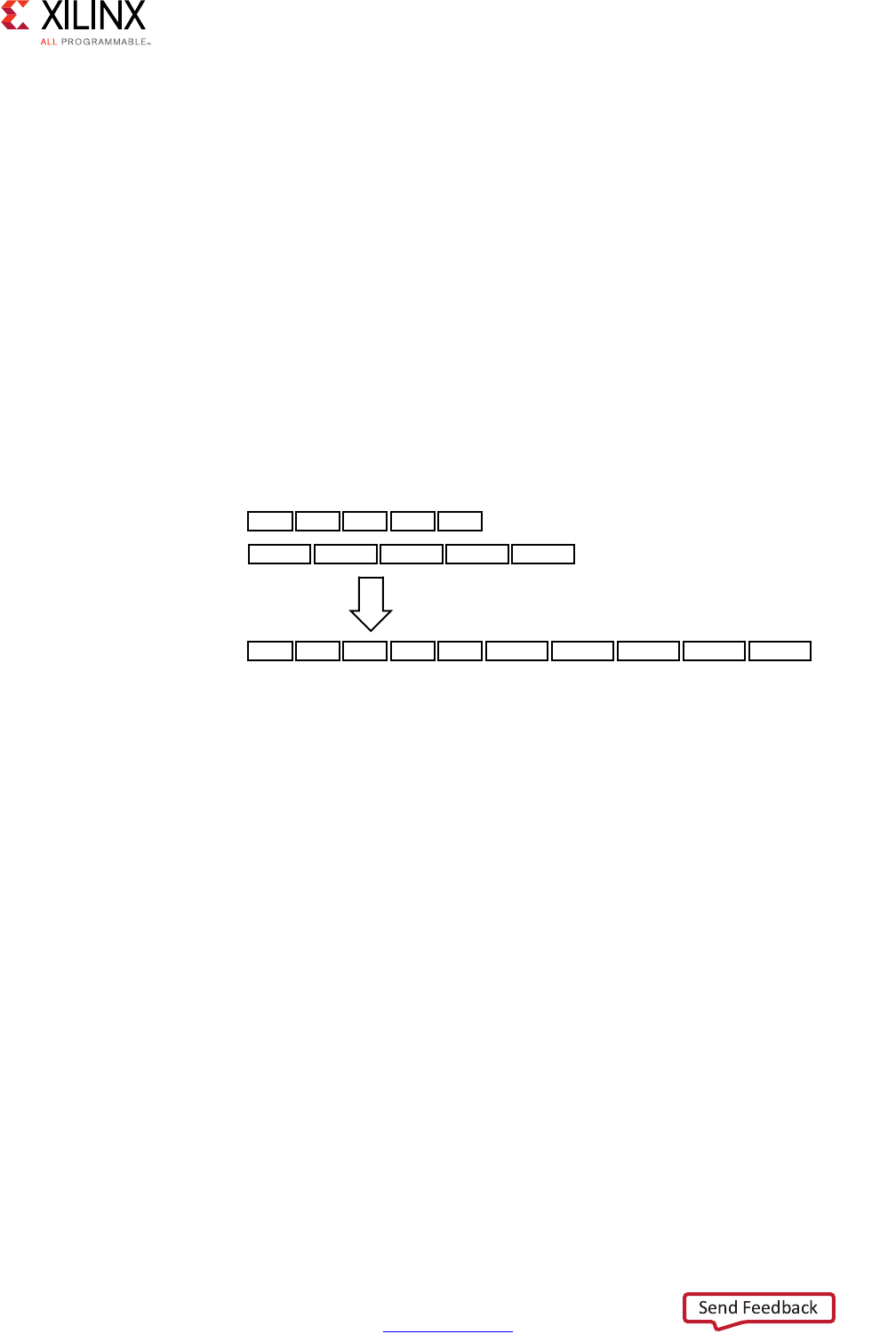
High-Level Synthesis 169
UG902 (v2017.1) April 5, 2017 www.xilinx.com
Chapter 1: High-Level Synthesis
Arrays array1 and array2 can be combined into a single array, specified as array3 in
the following example:
void foo (...) {
int8 array1[M];
int12 array2[N];
#pragma HLS ARRAY_MAP variable=array1 instance=array3 horizontal
#pragma HLS ARRAY_MAP variable=array2 instance=array3 horizontal
...
loop_1: for(i=0;i<M;i++) {
array1[i] = ...;
array2[i] = ...;
...
}
...
}
In this example, the ARRAY_MAP directive transforms the arrays as shown in the following
figure.
When using horizontal mapping, the smaller arrays are mapped into a larger array. The
mapping starts at location 0 in the larger array and follows in the order the commands are
specified. In the Vivado HLS GUI, this is based on the order the arrays are specified using
the menu commands. In the Tcl environment, this is based on the order the commands are
issued.
X-Ref Target - Figure 1-65
Figure 1-65: Horizontal Mapping
DUUD\>0@
1 1
DUUD\>1@
DUUD\>01@
/RQJHUDUUD\
KRUL]RQWDOH[SDQVLRQ
ZLWKPRUHHOHPHQWV
0 0
;
0 0 1 1
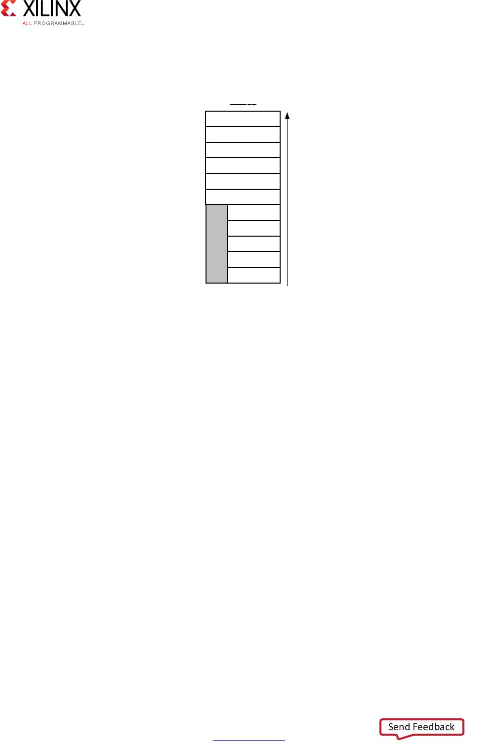
High-Level Synthesis 170
UG902 (v2017.1) April 5, 2017 www.xilinx.com
Chapter 1: High-Level Synthesis
When you use the horizontal mapping shown in Figure 1-65, the implementation in the
block RAM appears as shown in the following figure.
The offset option to the ARRAY_MAP directive is used to specify at which location
subsequent arrays are added when using the horizontal option. Repeating the previous
example, but reversing the order of the commands (specifying array2 then array1) and
adding an offset, as shown below:
void foo (...) {
int8 array1[M];
int12 array2[N];
#pragma HLS ARRAY_MAP variable=array2 instance=array3 horizontal
#pragma HLS ARRAY_MAP variable=array1 instance=array3 horizontal offset=2
...
loop_1: for(i=0;i<M;i++) {
array1[i] = ...;
array2[i] = ...;
...
}
...
}
This results in the transformation shown in the following figure.
X-Ref Target - Figure 1-66
Figure 1-66: Memory for Horizontal Mapping
N-1
RAM1P
N-2
1
0
M-1
M-2
1
0
M+N-1
Addresses
0
MSB LSB ;
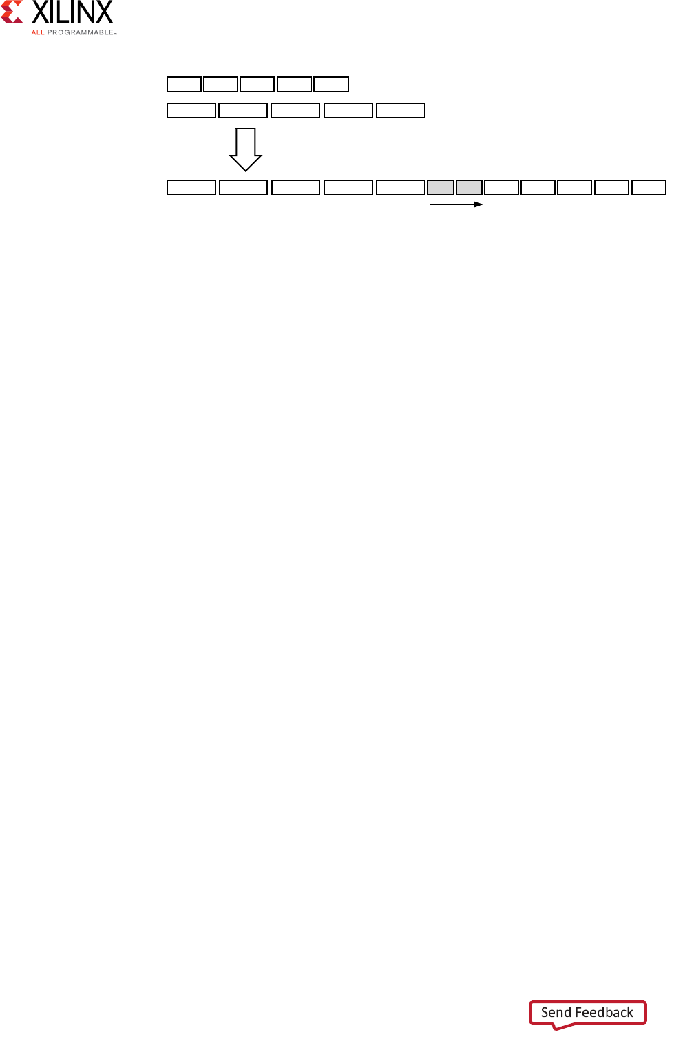
High-Level Synthesis 171
UG902 (v2017.1) April 5, 2017 www.xilinx.com
Chapter 1: High-Level Synthesis
After mapping, the newly formed array, array3 in the above examples, can be targeted
into a specific block RAM or UltraRAM by applying the RESOURCE directive to any of the
variables mapped into the new instance.
Although horizontal mapping can result in using less block RAM components and therefore
improve area, it does have an impact on the throughput and performance as there are now
fewer block RAM ports. To overcome this limitation, Vivado HLS also provides vertical
mapping.
Mapping Vertical Arrays
In vertical mapping, arrays are concatenated by to produce an array with higher
bit-widths.Vertical mapping is applied using the vertical option to the INLINE directive. The
following figure shows how the same example as before transformed when vertical
mapping mode is applied.
void foo (...) {
int8 array1[M];
int12 array2[N];
#pragma HLS ARRAY_MAP variable=array2 instance=array3 vertical
#pragma HLS ARRAY_MAP variable=array1 instance=array3 vertical
...
loop_1: for(i=0;i<M;i++) {
array1[i] = ...;
array2[i] = ...;
...
}
...
}
X-Ref Target - Figure 1-67
Figure 1-67: Horizontal Mapping with Offset
0 0
DUUD\>0@
1 1
DUUD\>1@
1 1
DUUD\>10@ 2 2
/RQJHUDUUD\
KRUL]RQWDOH[SDQVLRQ
ZLWKPRUHHOHPHQWV
2IIVHWRIIURPWKHHQG
RIDUUD\HOHPHQWV
0 0
;
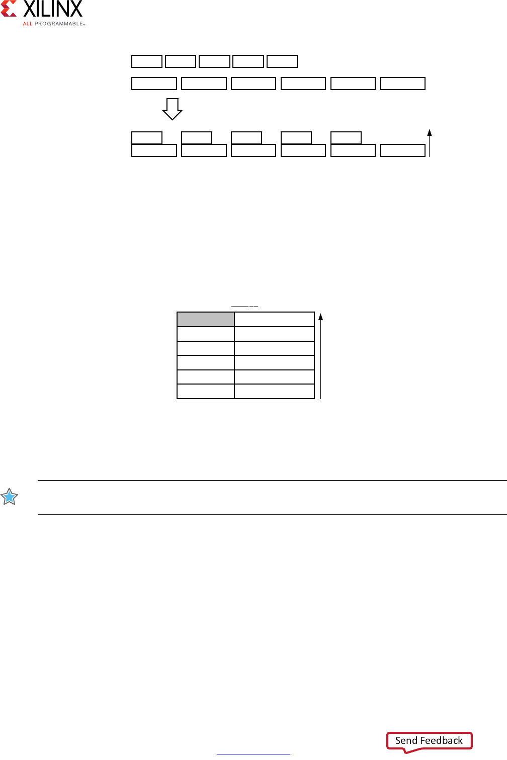
High-Level Synthesis 172
UG902 (v2017.1) April 5, 2017 www.xilinx.com
Chapter 1: High-Level Synthesis
In vertical mapping, the arrays are concatenated in the order specified by the command,
with the first arrays starting at the LSB and the last array specified ending at the MSB. After
vertical mapping the newly formed array, is implemented in a single block RAM component
as shown in the following figure.
Array Mapping and Special Considerations
IMPORTANT: The object for an array transformation must be in the source code prior to any other
directives being applied.
To map elements from a partitioned array into a single array with horizontal mapping,
the individual elements of the array to be partitioned must be specified in the ARRAY_MAP
directive. For example, the following Tcl commands partition array accum and map the
resulting elements back together.
#pragma HLS array_partition variable=m_accum cyclic factor=2 dim=1
#pragma HLS array_partition variable=v_accum cyclic factor=2 dim=1
#pragma HLS array_map variable=m_accum[0] instance=_accum horizontal
#pragma HLS array_map variable=v_accum[0] instance=mv_accum horizontal
#pragma HLS array_map variable=m_accum[1] instance=mv_accum_1 horizontal
#pragma HLS array_map variable=v_accum[1] instance=mv_accum_1 horizontal
X-Ref Target - Figure 1-68
Figure 1-68: Vertical Mapping
X-Ref Target - Figure 1-69
Figure 1-69: Memory for Vertical Mapping
DUUD\>0@ 0 0
DUUD\>1@ 1 1
9HUWLFDOH[SDQVLRQ
ZLWKPRUHELWV
DUUD\>1@
1 1
0 0
;
06%
/6%
1
5$03
1
1
$GGUHVVHV
06% /6%
0
0
;
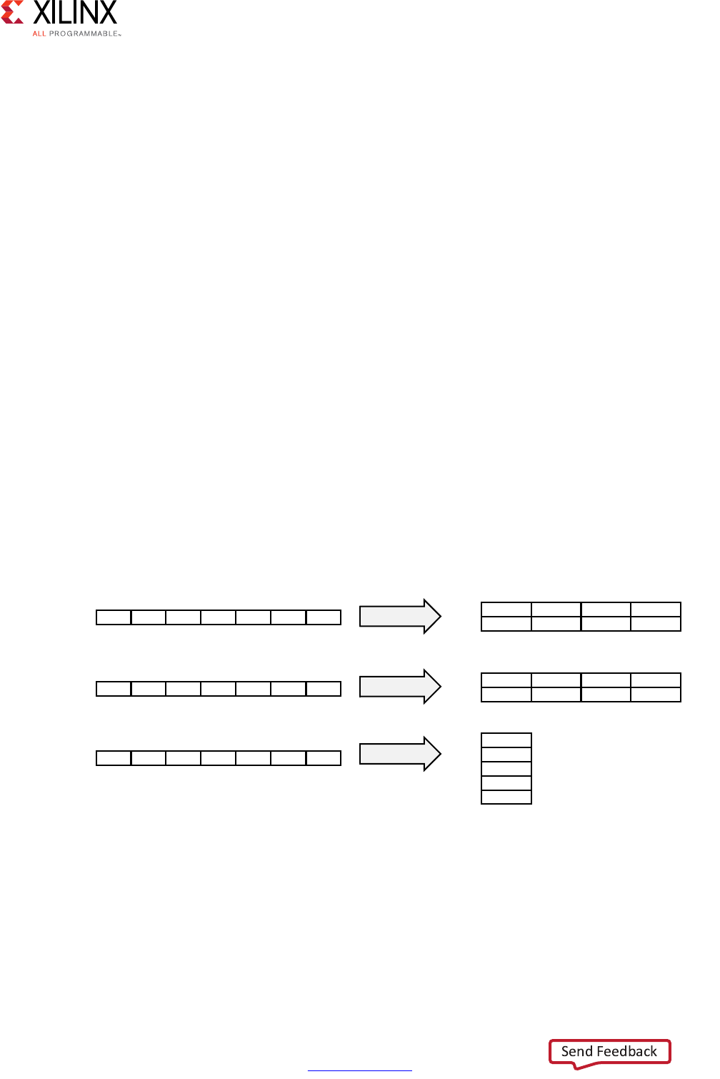
High-Level Synthesis 173
UG902 (v2017.1) April 5, 2017 www.xilinx.com
Chapter 1: High-Level Synthesis
It is possible to map a global array. However, the resulting array instance is global and any
local arrays mapped onto this same array instance become global. When local arrays of
different functions get mapped onto the same target array, then the target array instance
becomes global.
Array function arguments may only be mapped if they are arguments to the same function.
Array Reshaping
The ARRAY_RESHAPE directive combines ARRAY_PARTITIONING with the vertical mode of
ARRAY_MAP and is used to reduce the number of block RAM while still allowing the
beneficial attributes of partitioning: parallel access to the data.
Given the following example code:
void foo (...) {
int array1[N];
int array2[N];
int array3[N];
#pragma HLS ARRAY_RESHAPE variable=array1 block factor=2 dim=1
#pragma HLS ARRAY_RESHAPE variable=array2 cycle factor=2 dim=1
#pragma HLS ARRAY_RESHAPE variable=array3 complete dim=1
...
}
The ARRAY_RESHAPE directive transforms the arrays into the form shown in the following
figure.
The ARRAY_RESHAPE directive allows more data to be accessed in a single clock cycle. In
cases where more data can be accessed in a single clock cycle, Vivado HLS may
automatically unroll any loops consuming this data, if doing so will improve the throughput.
The loop can be fully or partially unrolled to create enough hardware to consume the
additional data in a single clock cycle. This feature is controlled using the config_unroll
command and the option tripcount_threshold. In the following example, any loops
X-Ref Target - Figure 1-70
Figure 1-70: Array Reshaping
1 1 1
1 1 1
1
1 1
1
EORFN
F\FOLF
FRPSOHWH
;
1 1 1
1 1 1
DUUD\>1@
DUUD\>1@
DUUD\>1@ 1
1
06%
/6%
06%
/6%
06%
/6%
DUUD\>1@
DUUD\>1@
DUUD\>@

High-Level Synthesis 174
UG902 (v2017.1) April 5, 2017 www.xilinx.com
Chapter 1: High-Level Synthesis
with a tripcount of less than 16 will be automatically unrolled if doing so improves the
throughput.
config_unroll -tripcount_threshold 16
Function Instantiation
Function instantiation is an optimization technique that has the area benefits of
maintaining the function hierarchy but provides an additional powerful option: performing
targeted local optimizations on specific instances of a function. This can simplify the control
logic around the function call and potentially improve latency and throughput.
The FUNCTION_INSTANTIATE directive exploits the fact that some inputs to a function may
be a constant value when the function is called and uses this to both simplify the
surrounding control structures and produce smaller more optimized function blocks. This is
best explained by example.
Given the following code:
void foo_sub(bool mode){
#pragma HLS FUNCTION_INSTANTIATE variable=mode
if (mode) {
// code segment 1
} else {
// code segment 2
}
}
void foo(){
#pragma HLS FUNCTION_INSTANTIATE variable=select
foo_sub(true);
foo_sub(false);
}
It is clear that function foo_sub has been written to perform multiple but exclusive
operations (depending on whether mode is true or not). Each instance of function foo_sub
is implemented in an identical manner: this is great for function reuse and area optimization
but means that the control logic inside the function must be more complex.

High-Level Synthesis 175
UG902 (v2017.1) April 5, 2017 www.xilinx.com
Chapter 1: High-Level Synthesis
The FUNCTION_INSTANTIATE optimization allows each instance to be independently
optimized, reducing the functionality and area. After FUNCTION_INSTANTIATE
optimization, the code above can effectively be transformed to have two separate
functions, each optimized for different possible values of mode, as shown:
void foo_sub1() {
// code segment 1
}
void foo_sub1() {
// code segment 2
}
void A(){
B1();
B2();
}
If the function is used at different levels of hierarchy such that function sharing is difficult
without extensive inlining or code modifications, function instantiation can provide the
best means of improving area: many small locally optimized copies are better than many
large copies that cannot be shared.
Controlling Hardware Resources
During synthesis Vivado HLS performs the following basic tasks:
• First, elaborates the C, C++ or SystemC source code into an internal database
containing operators.
The operators represent operations in the C code such as additions, multiplications,
array reads, and writes.
• Then, maps the operators on to cores which implement the hardware operations.
Cores are the specific hardware components used to create the design (such as adders,
multipliers, pipelined multipliers, and block RAM).
Control is provided over each of these steps, allowing you to control the hardware
implementation at a fine level of granularity.
Limiting the Number of Operators
Explicitly limiting the number of operators to reduce area may be required in some cases:
the default operation of Vivado HLS is to first maximize performance. Limiting the number
of operators in a design is a useful technique to reduce the area: it helps reduce area by
forcing sharing of the operations.

High-Level Synthesis 176
UG902 (v2017.1) April 5, 2017 www.xilinx.com
Chapter 1: High-Level Synthesis
The ALLOCATION directive allows you to limit how many operators, or cores or functions
are used in a design. For example, if a design called foo has 317 multiplications but the
FPGA only has 256 multiplier resources (DSP48s). The ALLOCATION directive shown below
directs Vivado HLS to create a design with maximum of 256 multiplication (mul) operators:
dout_t array_arith (dio_t d[317]) {
static int acc;
int i;
#pragma HLS ALLOCATION instances=mul limit=256 operation
for (i=0;i<317;i++) {
#pragma HLS UNROLL
acc += acc * d[i];
}
rerun acc;
}
Note: If you specify an ALLOCATION limit that is greater than needed, Vivado HLS attempts to use
the number of resources specified by the limit, or the maximum necessary, which reduces the
amount of sharing.

High-Level Synthesis 177
UG902 (v2017.1) April 5, 2017 www.xilinx.com
Chapter 1: High-Level Synthesis
You can use the type option to specify if the ALLOCATION directives limits operations,
cores, or functions. The following table lists all the operations that can be controlled using
the ALLOCATION directive.
Table 1-13: Vivado HLS Operators
Operator Description
add Integer Addition
ashr Arithmetic Shift-Right
dadd Double-precision floating point addition
dcmp Double -precision floating point comparison
ddiv Double -precision floating point division
dmul Double -precision floating point multiplication
drecip Double -precision floating point reciprocal
drem Double -precision floating point remainder
drsqrt Double -precision floating point reciprocal square root
dsub Double -precision floating point subtraction
dsqrt Double -precision floating point square root
fadd Single-precision floating point addition
fcmp Single-precision floating point comparison
fdiv Single-precision floating point division
fmul Single-precision floating point multiplication
frecip Single-precision floating point reciprocal
frem Single-precision floating point remainder
frsqrt Single-precision floating point reciprocal square root
fsub Single-precision floating point subtraction
fsqrt Single-precision floating point square root
icmp Integer Compare
lshr Logical Shift-Right
mul Multiplication
sdiv Signed Divider
shl Shift-Left
srem Signed Remainder
sub Subtraction
udiv Unsigned Division
urem Unsigned Remainder

High-Level Synthesis 178
UG902 (v2017.1) April 5, 2017 www.xilinx.com
Chapter 1: High-Level Synthesis
Globally Minimizing Operators
The ALLOCATION directive, like all directives, is specified inside a scope: a function, a loop
or a region. The config_bind configuration allows the operators to be minimized
throughout the entire design.
The minimization of operators through the design is performed using the min_op option in
the config_bind configuration. An any of the operators listed in Table 1-13 can be
limited in this fashion.
After the configuration is applied it applies to all synthesis operations performed in the
solution: if the solution is closed and re-opened the specified configuration still applies to
any new synthesis operations.
Any configurations applied with the config_bind configuration can be removed by using
the reset option or by using open_solution -reset to open the solution.
Controlling the Hardware Cores
When synthesis is performed, Vivado HLS uses the timing constraints specified by the clock,
the delays specified by the target device together with any directives specified by you, to
determine which core is used to implement the operators. For example, to implement a
multiplier operation Vivado HLS could use the combinational multiplier core or use a
pipeline multiplier core.
The cores which are mapped to operators during synthesis can be limited in the same
manner as the operators. Instead of limiting the total number of multiplication operations,
you can choose to limit the number of combinational multiplier cores, forcing any
remaining multiplications to be performed using pipelined multipliers (or vice versa). This is
performed by specifying the ALLOCATION directive type option to be core.
The RESOURCE directive is used to explicitly specify which core to use for specific
operations. In the following example, a 2-stage pipelined multiplier is specified to
implement the multiplication for variable The following command informs Vivado HLS to
use a 2-stage pipelined multiplier for variable c. It is left to Vivado HLS which core to use for
variable d.
int foo (int a, int b) {
int c, d;
#pragma HLS RESOURCE variable=c latency=2
c = a*b;
d = a*c;
return d;
}

High-Level Synthesis 179
UG902 (v2017.1) April 5, 2017 www.xilinx.com
Chapter 1: High-Level Synthesis
In the following example, the RESOURCE directives specify that the add operation for
variable temp and is implemented using the AddSub_DSP core. This ensures that the
operation is implemented using a DSP48 primitive in the final design - by default, add
operations are implemented using LUTs.
void apint_arith(dinA_t inA, dinB_t inB,
dout1_t *out1
) {
dout2_t temp;
#pragma HLS RESOURCE variable=temp core=AddSub_DSP
temp = inB + inA;
*out1 = temp;
}
The list_core command is used to obtain details on the cores available in the library. The
list_core can only be used in the Tcl command interface and a device must be specified
using the set_part command. If a device has not been selected, the command does not
have any effect.
The -operation option of the list_core command lists all the cores in the library that
can be implemented with the specified operation.The following table lists the cores used to
implement standard RTL logic operations (such as add, multiply, and compare).
Table 1-14: Functional Cores
Core Description
AddSub This core is used to implement both adders and subtractors.
AddSubnS N-stage pipelined adder or subtractor. Vivado HLS determines how many pipeline
stages are required.
AddSub_DSP This core ensures that the add or sub operation is implemented using a DSP48 (Using
the adder or subtractor inside the DSP48).
DivnS N-stage pipelined divider.
DSP48 Multiplications with bit-widths that allow implementation in a single DSP48
macrocell. This can include pipelined multiplications and multiplications grouped
with a pre-adder, post-adder, or both. This core can only be pipelined with a maximum
latency of 4. Values above 4 saturate at 4.
Mul Combinational multiplier with bit-widths that exceed the size of a standard DSP48
macrocell.
Note: Multipliers that can be implemented with a single DSP48 macrocell are mapped to the
DSP48 core.
MulnS N-stage pipelined multiplier with bit-widths that exceed the size of a standard DSP48
macrocell.
Note: Multipliers that can be implemented with a single DSP48 macrocell are mapped to the
DSP48 core.
Mul_LUT Multiplier implemented with LUTs.

High-Level Synthesis 180
UG902 (v2017.1) April 5, 2017 www.xilinx.com
Chapter 1: High-Level Synthesis
In addition to the standard cores, the following floating point cores are used when the
operation uses floating-point types. Refer to the documentation for each device to
determine if the floating-point core is supported in the device.
Table 1-15: Floating Point Cores
Core Description
FAddSub_nodsp Floating-point adder or subtractor implemented without any DSP48
primitives.
FAddSub_fulldsp Floating-point adder or subtractor implemented using only DSP48s
primitives.
FDiv Floating-point divider.
FExp_nodsp Floating-point exponential operation implemented without any DSP48
primitives.
FExp_meddsp Floating-point exponential operation implemented with balance of DSP48
primitives.
FExp_fulldsp Floating-point exponential operation implemented with only DSP48
primitives.
FLog_nodsp Floating-point logarithmic operation implemented without any DSP48
primitives.
FLog_meddsp Floating-point logarithmic operation with balance of DSP48 primitives.
FLog_fulldsp Floating-point logarithmic operation with only DSP48 primitives.
FMul_nodsp Floating-point multiplier implemented without any DSP48 primitives.
FMul_meddsp Floating-point multiplier implemented with balance of DSP48 primitives.
FMul_fulldsp Floating-point multiplier implemented with only DSP48 primitives.
FMul_maxdsp Floating-point multiplier implemented the maximum number of DSP48
primitives.
FRSqrt_nodsp Floating-point reciprocal square root implemented without any DSP48
primitives.
FRSqrt_fulldsp Floating-point reciprocal square root implemented with only DSP48
primitives.
FRecip_nodsp Floating-point reciprocal implemented without any DSP48 primitives.
FRecip_fulldsp Floating-point reciprocal implemented with only DSP48 primitives.
FSqrt Floating-point square root.
DAddSub_nodsp Double precision floating-point adder or subtractor implemented without
any DSP48 primitives.
DAddSub_fulldsp Double precision floating-point adder or subtractor implemented using
only DSP48s primitives.
DDiv Double precision floating-point divider.
DExp_nodsp Double precision floating-point exponential operation implemented
without any DSP48 primitives.
DExp_meddsp Double precision floating-point exponential operation implemented with
balance of DSP48 primitives.

High-Level Synthesis 181
UG902 (v2017.1) April 5, 2017 www.xilinx.com
Chapter 1: High-Level Synthesis
DExp_fulldsp Double precision floating-point exponential operation implemented with
only DSP48 primitives.
DLog_nodsp Double precision floating-point logarithmic operation implemented
without any DSP48 primitives.
DLog_meddsp Double precision floating-point logarithmic operation with balance of
DSP48 primitives.
DLog_fulldsp Double precision floating-point logarithmic operation with only DSP48
primitives.
DMul_nodsp Double precision floating-point multiplier implemented without any DSP48
primitives.
DMul_meddsp Double precision floating-point multiplier implemented with a balance of
DSP48 primitives.
DMul_fulldsp Double precision floating-point multiplier implemented with only DSP48
primitives.
DMul_maxdsp Double precision floating-point multiplier implemented with a maximum
number of DSP48 primitives.
DRSqrt Double precision floating-point reciprocal square root.
DRecip Double precision floating-point reciprocal.
DSqrt Double precision floating-point square root.
HAddSub_nodsp Half-precision floating-point adder or subtractor implemented without
DSP48 primitives.
HDiv Half-precision floating-point divider.
HMul_nodsp Half-precision floating-point multiplier implemented without DSP48
primitives.
HMul_fulldsp Half-precision floating-point multiplier implemented with only DSP48
primitives.
HMul_maxdsp Half-precision floating-point multiplier implemented with a maximum
number of DSP48 primitives.
HSqrt Half-precision floating-point square root.
Table 1-15: Floating Point Cores (Cont’d)
Core Description
FAddSub_nodsp Floating-point adder or subtractor implemented without any DSP48
primitives.

High-Level Synthesis 182
UG902 (v2017.1) April 5, 2017 www.xilinx.com
Chapter 1: High-Level Synthesis
The following table lists the cores used to implement storage elements, such as registers or
memories.
Table 1-16: Storage Cores
Core Description
FIFO A FIFO. Vivado HLS determines whether to implement this in the RTL with a
block RAM or as distributed RAM.
FIFO_ BRAM A FIFO implemented with a block RAM.
FIFO_LUTRAM A FIFO implemented as distributed RAM.
FIFO_SRL A FIFO implemented as with an SRL.
RAM_1P A single-port RAM. Vivado HLS determines whether to implement this in the
RTL with a block RAM or as distributed RAM.
RAM_1P_BRAM A single-port RAM implemented with a block RAM.
RAM_1P_LUTRAM A single-port RAM implemented as distributed RAM.
RAM_2P A dual-port RAM that allows read operations on one port and both read and
write operations on the other port. Vivado HLS determines whether to
implement this in the RTL with a block RAM or as distributed RAM.
RAM_2P_BRAM A dual-port RAM implemented with a block RAM that allows read operations
on one port and both read and write operations on the other port.
RAM_2P_LUTRAM A dual-port RAM implemented as distributed RAM that allows read operations
on one port and both read and write operations on the other port.
RAM_S2P_BRAM A dual-port RAM implemented with a block RAM that allows read operations
on one port and write operations on the other port.
RAM_S2P_LUTRAM A dual-port RAM implemented as distributed RAM that allows read operations
on one port and write operations on the other port.
RAM_T2P_BRAM A true dual-port RAM with support for both read and write on both ports
implemented with a block RAM.
ROM_1P A single-port ROM. Vivado HLS determines whether to implement this in the
RTL with a block RAM or with LUTs.
ROM_1P_BRAM A single-port ROM implemented with a block RAM.
ROM_nP_BRAM A multi-port ROM implemented with a block RAM. Vivado HLS automatically
determines the number of ports.
ROM_1P_LUTRAM A single-port ROM implemented with distributed RAM.
ROM_nP_LUTRAM A multi-port ROM implemented with distributed RAM. Vivado HLS
automatically determines the number of ports.
ROM_2P A dual-port ROM. Vivado HLS determines whether to implement this in the RTL
with a block RAM or as distributed ROM.
ROM_2P_BRAM A dual-port ROM implemented with a block RAM.
ROM_2P_LUTRAM A dual-port ROM implemented as distributed ROM.
XPM_MEMORY Specifies the array is to be implemented with an UltraRAM. This core is only
usable with devices supporting UltraRAM blocks.

High-Level Synthesis 183
UG902 (v2017.1) April 5, 2017 www.xilinx.com
Chapter 1: High-Level Synthesis
The resource directives uses the assigned variable as the target for the resource. Given the
code, the RESOURCE directive specifies the multiplication for out1 is implemented with a
3-stage pipelined multiplier.
void foo(...) {
#pragma HLS RESOURCE variable=out1 latency=3
// Basic arithmetic operations
*out1 = inA * inB;
*out2 = inB + inA;
*out3 = inC / inA;
*out4 = inD % inA;
}
If the assignment specifies multiple identical operators, the code must be modified to
ensure there is a single variable for each operator to be controlled. For example if only the
first multiplication in this example (inA * inB) is to be implemented with a pipelined
multiplier:
*out1 = inA * inB * inC;
The code should be changed to the following with the directive specified on the
Result_tmp variable:
#pragma HLS RESOURCE variable=Result_tmp latency=3
Result_tmp = inA * inB;
*out1 = Result_tmp * inC;
Globally Optimizing Hardware Cores
The config_bind configuration provides control over the binding process. The
configuration allows you to direct how much effort is spent when binding cores to
operators. By default Vivado HLS chooses cores which are the best balance between timing
and area. The config_bind influences which operators are used.
config_bind -effort [low | medium | high] -min_op <list>
The config_bind command can only be issued inside an active solution. The default run
strategies for the binding operation is medium.
•Low Effort: Spend less timing sharing, run time is faster but the final RTL may be
larger. Useful for cases when the designer knows there is little sharing possible or
desirable and does not wish to waste CPU cycles exploring possibilities.
•Medium Effort: The default, where Vivado HLS tries to share operations but endeavors
to finish in a reasonable time.
•High Effort: Try to maximize sharing and do not limit run time. Vivado HLS keeps
trying until all possible combinations of sharing is explored.

High-Level Synthesis 184
UG902 (v2017.1) April 5, 2017 www.xilinx.com
Chapter 1: High-Level Synthesis
Optimizing Logic
Controlling Operator Pipelining
Vivado HLS automatically determines the level of pipelining to use for internal operations.
You can use the RESOURCE directive with the -latency option to explicitly specify the
number of pipeline stages and override the number determined by Vivado HLS.
RTL synthesis might use the additional pipeline registers to help improve timing issues that
might result after place and route. Registers added to the output of the operation typically
help improve timing in the output datapath. Registers added to the input of the operation
typically help improve timing in both the input datapath and the control logic from the
FSM.
The rules for adding these additional pipeline stages are:
• If the latency is specified as 1 cycle more than the latency decided by Vivado HLS,
Vivado HLS adds new output registers to the output of the operation.
• If the latency is specified as 2 more than the latency decided by Vivado HLS, Vivado
HLS adds registers to the output of the operation and to the input side of the
operation.
• If the latency is specified as 3 or more cycles than the latency decided by Vivado HLS,
Vivado HLS adds registers to the output of the operation and to the input side of the
operation. Vivado HLS automatically determines the location of any additional
registers.
You can use the config_core configuration to pipeline all instances of a specific core
used in the design that have the same pipeline depth. To set this configuration:
1. Select Solutions > Solution Settings.
2. In the Solution Settings dialog box, select the General category, and click Add.
3. In the Add Command dialog box, select the config_core command, and specify the
parameters.
For example, the following configuration specifies that all operations implemented with
the DSP48 core are pipelined with a latency of 4, which is the maximum latency allowed
by this core:
config_core DSP48 -latency 4
The following configuration specifies that all block RAM implemented with the
RAM_1P_BRAM core are pipelined with a latency of 3:
config_core RAM_1P_BRAM -latency 3

High-Level Synthesis 185
UG902 (v2017.1) April 5, 2017 www.xilinx.com
Chapter 1: High-Level Synthesis
IMPORTANT: Vivado HLS only applies the core configuration to block RAM with an explicit RESOURCE
directive that specifies the core used to implemented the array. If an array is implemented using a
default core, the core configuration does not affect the block RAM.
See Table 1-16 for a list of all the cores you can use to implement arrays.
Optimizing Logic Expressions
During synthesis several optimizations, such as strength reduction and bit-width
minimization are performed. Included in the list of automatic optimizations is expression
balancing.
Expression balancing rearranges operators to construct a balanced tree and reduce latency.
• For integer operations expression balancing is on by default but may be disabled.
• For floating-point operations, expression balancing is off by default but may be
enabled.
Given the highly sequential code using assignment operators such as += and *= in the
following example:
data_t foo_top (data_t a, data_t b, data_t c, data_t d)
{
data_t sum;
sum = 0;
sum += a;
sum += b;
sum += c;
sum += d;
return sum;
}
Without expression balancing, and assuming each addition requires one clock cycle, the
complete computation for sum requires four clock cycles shown in the following figure.
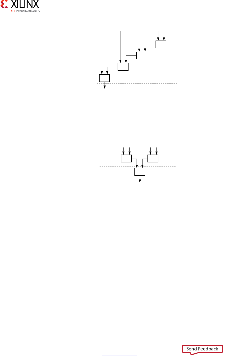
High-Level Synthesis 186
UG902 (v2017.1) April 5, 2017 www.xilinx.com
Chapter 1: High-Level Synthesis
However additions a+b and c+d can be executed in parallel allowing the latency to be
reduced. After balancing the computation completes in two clock cycles as shown in the
following figure. Expression balancing prohibits sharing and results in increased area.
For integers, you can disable expression balancing using the EXPRESSION_BALANCE
optimization directive with the off option. By default, Vivado HLS does not perform the
EXPRESSION_BALANCE optimization for operations of type float or double. When
synthesizing float and double types, Vivado HLS maintains the order of operations
performed in the C code to ensure that the results are the same as the C simulation. For
example, in the following code example, all variables are of type float or double. The
values of O1 and O2 are not the same even though they appear to perform the same basic
calculation.
A=B*C; A=B*F;
D=E*F; D=E*C;
O1=A*D O2=A*D;
This behavior is a function of the saturation and rounding in the C standard when
performing operation with types float or double. Therefore, Vivado HLS always
maintains the exact order of operations when variables of type float or double are
present and does not perform expression balancing by default.
X-Ref Target - Figure 1-71
Figure 1-71: Adder Tree
X-Ref Target - Figure 1-72
Figure 1-72: Adder Tree After Balancing
&\FOH
&\FOH
F
&\FOH
&\FOH
VXP
ED
ಯರ
;
G
&\FOH
&\FOH
EG
VXP ;
DF

High-Level Synthesis 187
UG902 (v2017.1) April 5, 2017 www.xilinx.com
Chapter 1: High-Level Synthesis
You can enable expression balancing with float and double types using the
configuration config_compile option as follows:
1. Select Solution > Solution Settings.
2. In the Solution Settings dialog box, click the General category, and click Add.
3. In the Add Command dialog box, select config_compile, and enable
unsafe_math_operations.
With this setting enabled, Vivado HLS might change the order of operations to produce a
more optimal design. However, the results of C/RTL cosimulation might differ from the C
simulation.
The unsafe_math_operations feature also enables the no_signed_zeros
optimization. The no_signed_zeros optimization ensures that the following expressions
used with float and double types are identical:
x - 0.0 = x;
x + 0.0 = x;
0.0 - x = -x;
x - x = 0.0;
x*0.0 = 0.0;
Without the no_signed_zeros optimization the expressions above would not be
equivalent due to rounding. The optimization may be optionally used without expression
balancing by selecting only this option in the config_compile configuration.
TIP: When the unsafe_math_operations and no_signed_zero optimizations are used, the RTL
implementation will have different results than the C simulation. The test bench should be capable of
ignoring minor differences in the result: check for a range, do not perform an exact comparison.

High-Level Synthesis 188
UG902 (v2017.1) April 5, 2017 www.xilinx.com
Chapter 1: High-Level Synthesis
Verifying the RTL
Post-synthesis verification is automated through the C/RTL co-simulation feature which
reuses the pre-synthesis C test bench to perform verification on the output RTL.
Automatically Verifying the RTL
C/RTL co-simulation uses the C test bench to automatically verify the RTL design. The
verification process consists of three phases, shown in Figure 1-73.
• The C simulation is executed and the inputs to the top-level function, or the
Device-Under-Test (DUT), are saved as “input vectors”.
• The “input vectors” are used in an RTL simulation using the RTL created by Vivado HLS.
The outputs from the RTL are save as “output vectors”.
• The “output vectors” from the RTL simulation are applied to C test bench, after the
function for synthesis, to verify the results are correct. The C test bench performs the
verification of the results.
The following messages are output by Vivado HLS to show the progress of the verification.
C simulation:
[SIM-14] Instrumenting C test bench (wrapc)
[SIM-302] Generating test vectors(wrapc)
At this stage, since the C simulation was executed, any messages written by the C test bench
will be output in console window or log file.
RTL simulation:
[SIM-333] Generating C post check test bench
[SIM-12] Generating RTL test bench
[SIM-323] Starting Verilog simulation (Issued when Verilog is the RTL verified)
[SIM-322] Starting VHDL simulation (Issued when VHDL is the RTL verified)
At this stage, any messages from the RTL simulation are output in console window or log
file.
C test bench results checking:
[SIM-316] Starting C post checking
[SIM-1000] C/RTL co-simulation finished: PASS (If test bench returns a 0)
[SIM-4] C/RTL co-simulation finished: FAIL (If the test bench returns non-zero)
The importance of the C test bench in the C/RTL co-simulation flow is discussed below.
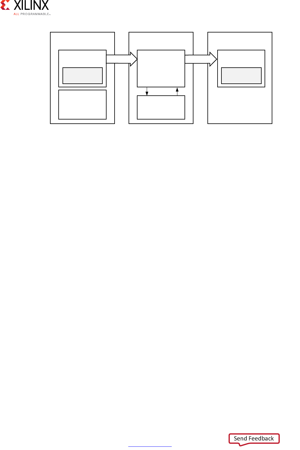
High-Level Synthesis 189
UG902 (v2017.1) April 5, 2017 www.xilinx.com
Chapter 1: High-Level Synthesis
The following is required to use C/RTL co-simulation feature successfully:
• The test bench must be self-checking and return a value of 0 if the test passes or
returns a non-zero value if the test fails.
• The correct interface synthesis options must be selected.
• Any 3rd-party simulators must be available in the search path.
• Any arrays or structs on the design interface cannot use the optimization directives or
combinations of optimization directives listed in Unsupported Optimizations for
Cosimulation.
X-Ref Target - Figure 1-73
Figure 1-73: RTL Verification Flow
:UDS&6LPXODWLRQ
7HVW%HQFK
'87
57/6LPXODWLRQ
$XWR7%
79,QGDW
57/0RGXOH
3RVW&KHFNLQJ
6LPXODWLRQ
792XWGDW
5HVXOW
&KHFNLQJ
7HVW%HQFK
5HVXOW
&KHFNLQJ
;
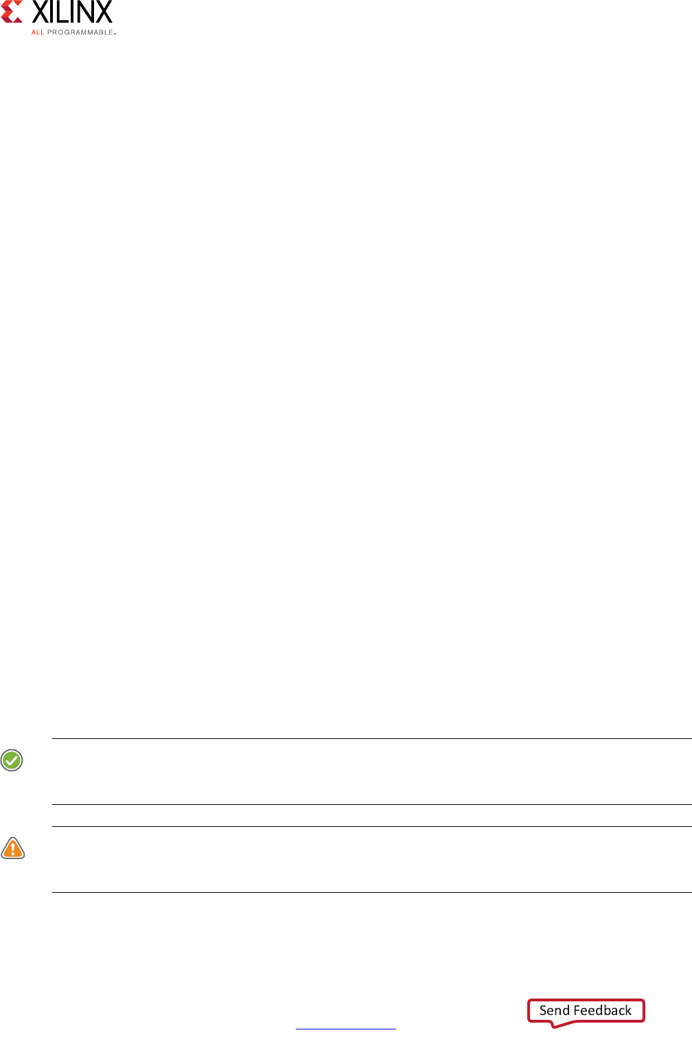
High-Level Synthesis 190
UG902 (v2017.1) April 5, 2017 www.xilinx.com
Chapter 1: High-Level Synthesis
Test Bench Requirements
To verify the RTL design produces the same results as the original C code, use a
self-checking test bench to execute the verification. The following code example shows the
important features of a self-checking test bench:
int main () {
int ret=0;
…
// Execute (DUT) Function
…
// Write the output results to a file
…
// Check the results
ret = system("diff --brief -w output.dat output.golden.dat");
if (ret != 0) {
printf("Test failed !!!\n");
ret=1;
} else {
printf("Test passed !\n");
}
…
return ret;
}
This self-checking test bench compares the results against known good results in the
output.golden.dat file.
Note: There are many ways to perform this checking. This is just one example.
In the Vivado HLS design flow, the return value to function main() indicates the following:
• Zero: Results are correct.
• Non-zero value: Results are incorrect.
Note: The test bench can return any non-zero value. A complex test bench can return different
values depending on the type of difference or failure. If the test bench returns a non-zero value
after C simulation or C/RTL co-simulation, Vivado HLS reports an error and simulation fails.
RECOMMENDED: Because the system environment (for example, Linux, Windows, or Tcl) interprets the
return value of the main() function, it is recommended that you constrain the return value to an 8-bit
range for portability and safety.
CAUTION! You are responsible for ensuring that the test bench checks the results. If the test bench does
not check the results but returns zero, Vivado HLS indicates that the simulation test passed even though
the results were not actually checked.

High-Level Synthesis 191
UG902 (v2017.1) April 5, 2017 www.xilinx.com
Chapter 1: High-Level Synthesis
Interface Synthesis Requirements
To use the C/RTL cosimulation feature to verify the RTL design, one or more of the following
conditions must be true:
• Top-level function must be synthesized using an ap_ctrl_hs or ap_ctrl_chain
block-level interface.
• Design must be purely combinational.
• Top-level function must have an initiation interval of 1.
• Interface must be all arrays that are streaming and implemented with ap_fifo, ap_hs,
or axis interface modes.
Note: The hls::stream variables are automatically implemented as ap_fifo interfaces.
If at least one of these conditions is not met, C/RTL co-simulation halts with the following
message:
@E [SIM-345] Cosim only supports the following 'ap_ctrl_none' designs: (1)
combinational designs; (2) pipelined design with task interval of 1; (3) designs with
array streaming or hls_stream ports.
@E [SIM-4] *** C/RTL co-simulation finished: FAIL ***
IMPORTANT: If the design is specified to use the block-level IO protocol ap_ctrl_none and the design
contains any hls::stream variables which employ non-blocking behavior, C/RTL co-simulation is not
guaranteed to complete.
If any top-level function argument is specified as an AXI-Lite interface, the function return
must also be specified as an AXI-Lite interface.
RTL Simulator Support
After ensuring that the preceding requirements are met, you can use C/RTL co-simulation to
verify the RTL design using Verilog or VHDL. The default simulation language is Verilog.
However, you can also specify VHDL. For information on changing the defaults, see Using
C/RTL Co-Simulation. While the default simulator is Vivado Simulator (XSim), you can use
any of the following simulators to run C/RTL co-simulation:
• Vivado Simulator (XSim)
• ModelSim simulator
• VCS simulator (Linux only)
• NC-Sim simulator (Linux only)
• Riviera simulator (PC only)

High-Level Synthesis 192
UG902 (v2017.1) April 5, 2017 www.xilinx.com
Chapter 1: High-Level Synthesis
IMPORTANT: To verify an RTL design using the third-party simulators (for example, ModelSim, VCS,
Riviera), you must include the executable to the simulator in the system search path, and the
appropriate license must be available. See the third-party vendor documentation for details on
configuring these simulators.
IMPORTANT: When verifying a SystemC design, you must select the ModelSim simulator and ensure it
includes C compiler capabilities with appropriate licensing.
Unsupported Optimizations for Cosimulation
The automatic RTL verification does not support cases where multiple transformations that
are performed upon arrays or arrays within structs on the interface.
In order for automatic verification to be performed, arrays on the function interface, or
array inside structs on the function interface, can use any of the following optimizations,
but not two or more:
• Vertical mapping on arrays of the same size
•Reshape
•Partition
• Data Pack on structs
Verification by C/RTL co-simulation cannot be performed when the following optimizations
are used on top-level function interface.
• Horizontal Mapping
• Vertical Mapping of arrays of different sizes
• Data Pack on structs containing other structs as members
Simulating IP Cores
When the design is implemented with floating-point cores, bit-accurate models of the
floating-point cores must be made available to the RTL simulator. This is automatically
accomplished if the RTL simulation is performed using the following:
• Verilog and VHDL using the Xilinx Vivado Simulator
• Verilog and VHDL using the Mentor Graphics Questa Advanced Simulator
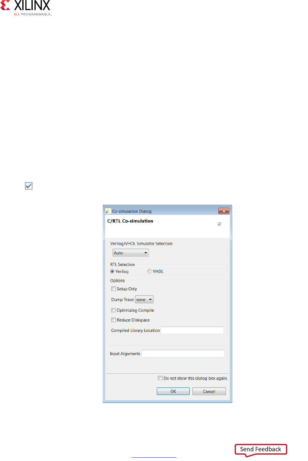
High-Level Synthesis 193
UG902 (v2017.1) April 5, 2017 www.xilinx.com
Chapter 1: High-Level Synthesis
For other supported HDL simulators the Xilinx floating point library must be pre-compiled
and added to the simulator libraries. The following example steps demonstrate how the
floating point library may be compiled in verilog for use with the VCS simulator:
1. Open Vivado (not Vivado HLS) and issue the following command in the Tcl console
window:
compile_simlib -simulator vcs_mx -family all -language verilog
2. This command creates floating-point library in the current directory.
3. Refer to the Vivado console window for directory name, example ./rev3_1
This library may then be referred to from within Vivado HLS:
cosim_design -trace_level all -tool vcs -compiled_library_dir/
<path_to_compile_library>/rev3_1
Using C/RTL Co-Simulation
To perform C/RTL co-simulation from the GUI, click the C/RTL Cosimulation toolbar button
. This opens the simulation wizard window shown in the following figure.
X-Ref Target - Figure 1-74
Figure 1-74: C/RTL Co-Simulation Wizard

High-Level Synthesis 194
UG902 (v2017.1) April 5, 2017 www.xilinx.com
Chapter 1: High-Level Synthesis
Select the RTL that is simulated (Verilog or VHDL). The drop-down menu allows the
simulator to be selected. The defaults and possible selections are noted above in RTL
Simulator Support.
Following are the options:
• Setup Only: This creates all the files (wrappers, adapters, and scripts) required to run
the simulation but does not execute the simulator. The simulation can be run in the
command shell from within the appropriate RTL simulation folder
<solution_name>/sim/<RTL>.
• Dump Trace: This generates a trace file for every function, which is saved to the
<solution>/sim/<RTL> folder. The drop-down menu allows you to select which
signals are saved to the trace file. You can choose to trace all signals in the design,
trace just the top-level ports, or trace no signals. For details on using the trace file, see
the documentation for the selected RTL simulator.
• Optimizing Compile: This ensures a high level of optimization is used to compile the C
test bench. Using this option increases the compile time but the simulation executes
faster.
• Reduce Disk Space: The flow shown Figure 1-73 in saves the results for all transactions
before executing RTL simulation. In some cases, this can result in large data files. The
reduce_diskspace option can be used to execute one transaction at a time and
reduce the amount of disk space required for the file. If the function is executed N
times in the C test bench, the reduce_diskspace option ensure N separate RTL
simulations are performed. This causes the simulation to run slower.
• Compiled Library Location: This specifies the location of the compiled library for a
third-party RTL simulator.
Note: If you are simulating with a third-party RTL simulator and the design uses IP, you must use
an RTL simulation model for the IP before performing RTL simulation. To create or obtain the RTL
simulation model, contact your IP provider.
• Input Arguments: This allows the specification of any arguments required by the test
bench.
Executing RTL Simulation
Vivado HLS executes the RTL simulation in the project sub-directory:
<SOLUTION>/sim/<RTL>
where
• SOLUTION is the name of the solution.
• RTL is the RTL type chosen for simulation.

High-Level Synthesis 195
UG902 (v2017.1) April 5, 2017 www.xilinx.com
Chapter 1: High-Level Synthesis
Any files written by the C test bench during co-simulation and any trace files generated by
the simulator are written to this directory. For example, if the C test bench save the output
results for comparison, review the output file in this directory and compare it with the
expected results.
Verification of Directives
C/RTL co-simulation automatically verifies aspects of the DEPENDENCE and DATAFLOW
directives.
If the DATAFLOW directive is used to pipeline tasks, it inserts channels between the tasks to
facilitate the flow of data between them. It is typical for the channels to be implemented
with FIFOs and the FIFO depth specified using the STREAM directive or the
config_dataflow command. If a FIFO depth is sized too small, the RTL simulation can
stall. For example, if a FIFO is specified with a depth of 2 but the producer task writes three
values before any data values are read by the consumer task, the FIFO blocks the producer.
In some conditions this can cause the entire design to stall.
C/RTL co-simulation issues a message, as shown below, indicating the channel in the
DATAFLOW region is causing the RTL simulation to stall.
//////////////////////////////////////////////////////////////////////////////
// ERROR!!! DEADLOCK DETECTED at 1292000 ns! SIMULATION WILL BE STOPPED! //
//////////////////////////////////////////////////////////////////////////////
/////////////////////////
// Dependence circle 1:
// (1): Process: hls_fft_1kxburst.fft_rank_rad2_nr_man_9_U0
// Channel: hls_fft_1kxburst.stage_chan_in1_0_V_s_U, FULL
// Channel: hls_fft_1kxburst.stage_chan_in1_1_V_s_U, FULL
// Channel: hls_fft_1kxburst.stage_chan_in1_0_V_1_U, FULL
// Channel: hls_fft_1kxburst.stage_chan_in1_1_V_1_U, FULL
// (2): Process: hls_fft_1kxburst.fft_rank_rad2_nr_man_6_U0
// Channel: hls_fft_1kxburst.stage_chan_in1_2_V_s_U, EMPTY
// Channel: hls_fft_1kxburst.stage_chan_in1_2_V_1_U, EMPTY
/////////////////////////////////
// Totally 1 circles detected!
/////////////////////////////////////////////////////////////
In this case, review the implementation of the channels between the tasks and ensure any
FIFOs are large enough to hold the data being generated.
In a similar manner, the RTL test bench is also configured to automatically confirm false
dependencies specified using the DEPENDENCE directive. This indicates the dependency is
not false and must be removed to achieve a functionally valid design.
Analyzing RTL Simulations
When the C/RTL cosimulation completes, the simulation report opens and shows the
measured latency and II. These results may differ from the values reported after HLS
synthesis which are based on the absolute shortest and longest paths through the design.

High-Level Synthesis 196
UG902 (v2017.1) April 5, 2017 www.xilinx.com
Chapter 1: High-Level Synthesis
The results provided after C/RTL cosimulation show the actual values of latency and II for
the given simulation data set (and may change if different input stimuli is used).
In non-pipelined designs, C/RTL Cosimulation measures latency between ap_start and
ap_done signals. The II is 1 more than the latency, because the design reads new inputs 1
cycle after all operations are complete. The design only starts the next transaction after the
current transaction is complete.
In pipelined designs, the design might read new inputs before the first transaction
completes, and there might be multiple ap_start and ap_ready signals before a
transaction completes. In this case, C/RTL cosimulation measures the latency as the number
of cycles between data input values and data output values. The II is the number of cycles
between ap_ready signals, which the design uses to requests new inputs.
Note: For pipelined designs, the II value for C/RTL cosimulation is only valid if the design is
simulated for multiple transactions.
Optionally, you can review the waveform from C/RTL cosimulation using the Open Wave
Viewer toolbar button. To view RTL waveforms, you must select the following options
before executing C/RTL cosimulation:
• Verilog/VHDL Simulator Selection: Select Vivado Simulator. For Xilinx 7 series and
later devices, you can alternatively select Auto.
•Dump Trace: Select all or port.
When C/RTL cosimulation completes, the Open Wave Viewer toolbar button opens the RTL
waveforms in the Vivado IDE.
Note: When you open the Vivado IDE using this method, you can only use the waveform analysis
features, such as zoom, pan, and waveform radix.
Debugging C/RTL Cosimulation
When C/RTL cosimulation completes, Vivado HLS typically indicates that the simulations
passed and the functionality of the RTL design matches the initial C code. When the C/RTL
cosimulation fails, Vivado HLS issues the following message:
@E [SIM-4] *** C/RTL co-simulation finished: FAIL ***
Following are the primary reasons for a C/RTL cosimulation failure:
• Incorrect environment setup
• Unsupported or incorrectly applied optimization directives
• Issues with the C test bench or the C source code

High-Level Synthesis 197
UG902 (v2017.1) April 5, 2017 www.xilinx.com
Chapter 1: High-Level Synthesis
To debug a C/RTL cosimulation failure, run the checks described in the following sections.
If you are unable to resolve the C/RTL cosimulation failure, see Xilinx Support for support
resources, such as answers, documentation, downloads, and forums.
Setting up the Environment
Check the environment setup as shown in the following table.
Optimization Directives
Check the optimization directives as shown in the following table.
Table 1-17: Debugging Environment Setup
Questions Actions to Take
Are you using a third-party simulator? Ensure the path to the simulator executable is specified in the system
search path.
Note: When using the Vivado simulator, you do not need to specify a search
path.
Are you running Linux? Ensure that your setup files (for example .cshrc or .bashrc) do not
have a change directory command. When C/RTL cosimulation starts, it
spawns a new shell process. If there is a cd command in your setup files,
it causes the shell to run in a different location and eventually C/RTL
cosimulation fails.
Table 1-18: Debugging Optimization Directives
Questions Actions to Take
Are you using the DEPENDENCE
directive?
Remove the DEPENDENCE directives from the design to see if C/RTL
cosimulation passes. If cosimulation passes, it likely indicates that the
TRUE or FALSE setting for the DEPENDENCE directive is incorrect.
Does the design use volatile pointers
on the top-level interface?
Ensure the DEPTH option is specified on the INTERFACE directive. When
volatile pointers are used on the interface, you must specify the number
of read/writes performed on the port in each transaction or each
execution of the C function.
Are you using FIFOs with the
DATAFLOW optimization?
• Check to see if C/RTL cosimulation passes with the standard
ping-pong buffers.
• Check to see if C/RTL cosimulation passes without specifying the size
for the FIFO channels. This ensures that the channel defaults to the
size of the array in the C code.
• Reduce the size of the FIFO channels until C/RTL cosimulation stalls.
Stalling indicates a channel size that is too small. Review your design
to determine the optimal size for the FIFOs. You can use the STREAM
directive to specify the size of individual FIFOs.

High-Level Synthesis 198
UG902 (v2017.1) April 5, 2017 www.xilinx.com
Chapter 1: High-Level Synthesis
C Test Bench and C Source Code
Check the C test bench and C source code as shown in the following table.
Are you using supported interfaces? Ensure you are using supported interface modes. For details, see
Interface Synthesis Requirements.
Are you applying multiple
optimization directives to arrays on
the interface?
Ensure you are using optimizations that are designed to work together.
For details, see Unsupported Optimizations for Cosimulation.
Table 1-18: Debugging Optimization Directives (Cont’d)
Questions Actions to Take
Table 1-19: Debugging the C Test Bench and C Source Code
Questions Actions to Take
Does the C test bench check the results
and return the value 0 (zero) if the
results are correct?
Ensure the C test bench returns the value 0 for C/RTL cosimulation. Even
if the results are correct, the C/RTL cosimulation feature reports a failure
if the C test bench fails to return the value 0.
Is the C test bench creating input data
based on a random number?
Change the test bench to use a fixed seed for any random number
generation. If the seed for random number generation is based on a
variable, such as a time-based seed, the data used for simulation is
different each time the test bench is executed, and the results are
different.
Are you using pointers on the top-level
interface that are accessed multiple
times?
Use a volatile pointer for any pointer that is accessed multiple times
within a single transaction (one execution of the C function). If you do
not use a volatile pointer, everything except the first read and last
write is optimized out to adhere to the C standard.
Does the C code contain undefined
values or perform out-of-bounds array
accesses?
• Confirm all arrays are correctly sized to match all accesses. Loop
bounds that exceed the size of the array are a common source of
issues (for example, N accesses for an array sized at N-1).
• Confirm that the results of the C simulation are as expected and that
output values were not assigned random data values.
• Consider using the industry-standard Valgrind application outside of
the Vivado HLS design environment to confirm that the C code does
not have undefined or out-of-bounds issues.
Note: It is possible for a C function to execute and complete even if some
variables are undefined or are out-of-bounds. In the C simulation, undefined
values are assigned a random number. In the RTL simulation, undefined values
are assigned an unknown or X value.
Are you using floating-point math
operations in the design?
• Check that the C test bench results are within an acceptable error
range instead of performing an exact comparison. For some of the
floating point math operations, the RTL implementation is not
identical to the C. For details, see Verification and Math Functions in
Chapter 2.
• Ensure that the RTL simulation models for the floating-point cores are
provided to the third-party simulator. For details, see Simulating IP
Cores.

High-Level Synthesis 199
UG902 (v2017.1) April 5, 2017 www.xilinx.com
Chapter 1: High-Level Synthesis
Exporting the RTL Design
The final step in the Vivado HLS flow is to export the RTL design as a block of Intellectual
Property (IP) which can be used by other tools in the Xilinx design flow. The RTL design can
be packaged into the following output formats:
• IP Catalog formatted IP for use with the Vivado Design Suite
• System Generator for DSP IP for use with Vivado System Generator for DSP
• Synthesized Checkpoint (.dcp)
Are you using Xilinx IP blocks and a
third-party simulator?
Ensure that the path to the Xilinx IP HDL models is provided to the
third-party simulator.
Are you using the hls::stream
construct in the design that changes
the data rate (for example, decimation
or interpolation)?
Analyze the design and use the STREAM directive to increase the size of
the FIFOs used to implement the hls::stream.
Note: By default, an hls::stream is implemented as a FIFO with a depth of 1.
If the design results in an increase in the data rate (for example, an interpolation
operation), a default FIFO size of 1 might be too small and cause the C/RTL
cosimulation to stall.
Are you using very large data sets in
the simulation?
Use the reduce_diskspace option when executing C/RTL
cosimulation. In this mode, Vivado HLS only executes 1 transaction at a
time. The simulation might run marginally slower, but this limits storage
and system capacity issues.
Note: The C/RTL cosimulation feature verifies all transaction at one time. If the
top-level function is called multiple times (for example, to simulate multiple
frames of video), the data for the entire simulation input and output is stored on
disk. Depending on the machine setup and OS, this might cause performance or
execution issues.
Table 1-19: Debugging the C Test Bench and C Source Code (Cont’d)
Questions Actions to Take

High-Level Synthesis 200
UG902 (v2017.1) April 5, 2017 www.xilinx.com
Chapter 1: High-Level Synthesis
The following table shows the formats you can export with details about each.
In addition to the packaged output formats, the RTL files are available as standalone files
(not part of a packaged format) in the verilog and vhdl directories located within the
implementation directory <project_name>/<solution_name>/impl.
In addition to the RTL files, these directories also contain project files for the Vivado Design
Suite. Opening the file project.xpr causes the design (Verilog or VHDL) to be opened in
a Vivado project where the design may be analyzed. If C/RTL Cosimulation was executed in
the Vivado HLS project, the C/RTL C/RTL Cosimulation files are available inside the Vivado
project.
Table 1-20: RTL Export Selections
Format Selection Subfolder Comments
IP Catalog ip Contains a ZIP file which can be added to the Vivado IP
Catalog. The ip folder also contains the contents of the
ZIP file (unzipped).
This option is not available for FPGA devices older than
7-series or Zynq-7000 AP SoC.
System Generator for DSP sysgen This output can be added to the Vivado edition of System
Generator for DSP.
This option is not available for FPGA devices older than
7-series or Zynq-7000 AP SoC.
Synthesized Checkpoint
(.dcp)
ip This option creates Vivado checkpoint files which can be
added directly into a design in the Vivado Design Suite.
This option requires RTL synthesis to be performed. When
this option is selected, the flow option with setting syn
is automatically selected.
The output includes an HDL wrapper you can use to
instantiate the IP into an HDL file.
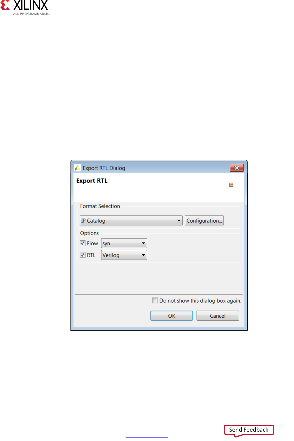
High-Level Synthesis 201
UG902 (v2017.1) April 5, 2017 www.xilinx.com
Chapter 1: High-Level Synthesis
Synthesizing the RTL
When Vivado HLS reports on the results of synthesis, it provides an estimation of the results
expected after RTL synthesis: the expected clock frequency, the expected number of
registers, LUTs and block RAMs. These results are estimations because Vivado HLS cannot
know what exact optimizations RTL synthesis performs or what the actual routing delays
will be, and hence cannot know the final area and timing values.
Before exporting a design, you have the opportunity to execute logic synthesis and confirm
the accuracy of the estimates. The flow option shown the following figure invokes RTL
synthesis with the syn option or RTL synthesis and implementation with the impl option.
during the export process and synthesizes the RTL design to gates or the placed and routed
implementation.
Note: The RTL synthesis option is provided to confirm the reported estimates. In most cases, these
RTL results are not included in the packaged IP.
For most export formats, the RTL synthesis is executed in the verilog or vhdl directories,
whichever HDL was chosen for RTL synthesis using the drop-down menu in the preceding
figure, but the results of RTL synthesis are not included in the packaged IP.
Synthesized Checkpoint (.dcp), a design checkpoint, is always exported as synthesized RTL.
The flow option may be used to evaluate the results of synthesis or implementation, but the
exported package always contains a synthesized netlist.
X-Ref Target - Figure 1-75
Figure 1-75: Export RTL Dialog Box

High-Level Synthesis 202
UG902 (v2017.1) April 5, 2017 www.xilinx.com
Chapter 1: High-Level Synthesis
Packaging IP Catalog Format
Upon completion of synthesis and RTL verification, open the Export RTL dialog box by
clicking the Export RTL toolbar button .
Select the IP Catalog format in the Format Selection section.
The configuration options allow the following identification tags to be embedded in
the exported package. These fields can be used to help identify the packaged RTL inside the
Vivado IP Catalog.
The configuration information is used to differentiate between multiple instances of the
same design when the design is loaded into the IP Catalog. For example, if an
implementation is packaged for the IP Catalog and then a new solution is created and
packaged as IP, the new solution by default has the same name and configuration
information. If the new solution is also added to the IP Catalog, the IP Catalog will identify
it as an updated version of the same IP and the last version added to the IP Catalog will be
used.
An alternative method is to use the prefix option in the config_rtl configuration to
rename the output design and files with a unique prefix.
If no values are provided in the configuration setting the following values are used:
• Vendor: xilinx.com
• Library: hls
• Version: 1.0
• Description: An IP generated by Vivado HLS
•Display Name: This field is left blank by default
• Taxonomy: This field is left blank by default
After the packaging process is complete, the.zip file archive in directory
<project_name>/<solution_name>/impl/ip can be imported into the Vivado IP
catalog and used in any Vivado design (RTL or IP Integrator).
Software Driver Files
For designs that include AXI4-Lite slave interfaces, a set of software driver files is created
during the export process. These C driver files can be included in an SDK C project and used
to access the AXI4-Lite slave port.
The software driver files are written to directory
<project_name>/<solution_name>/impl/ip/drivers and are included in the
package .zip archive. Refer to AXI4-Lite Interface for details on the C driver files.
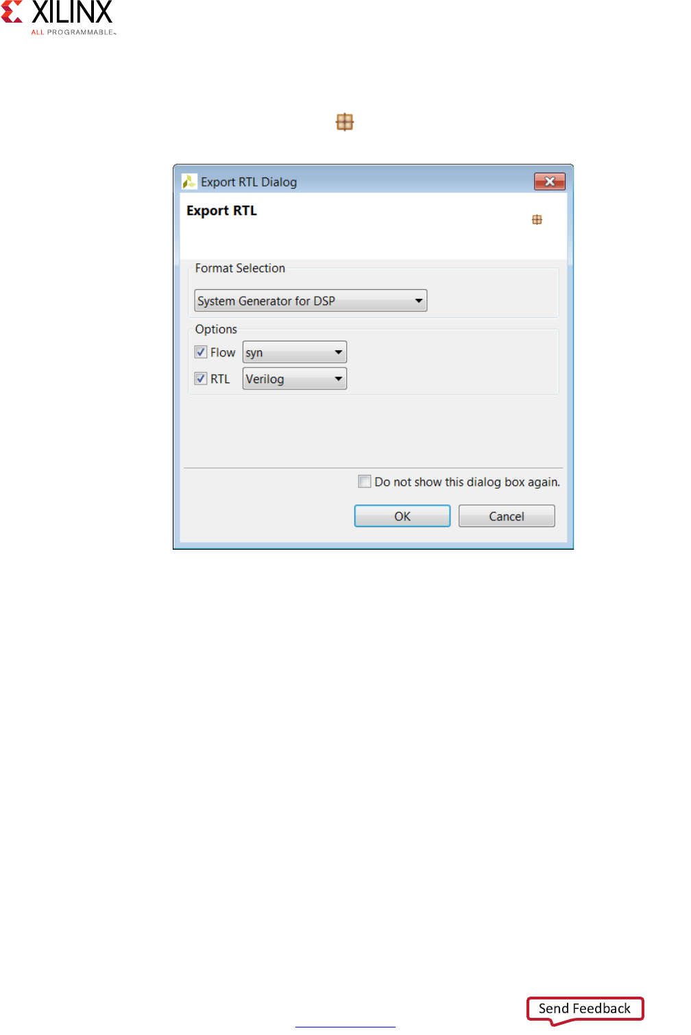
High-Level Synthesis 203
UG902 (v2017.1) April 5, 2017 www.xilinx.com
Chapter 1: High-Level Synthesis
Exporting IP to System Generator
Upon completion of synthesis and RTL verification, open the Export RTL dialog box by
clicking the Export RTL toolbar button .
If post-place-and-route resource and timing statistic for the IP block are desired then select
the Flow option and select the desired RTL language.
Pressing OK generates the IP package. This package is written to the
<project_name>/<solution_name>/impl/sysgen directory. And contains
everything need to import the design to System Generator.
If the Flow option was selected, RTL synthesis is executed and the final timing and
resources reported but not included in the IP package. See the RTL synthesis section above
for more details on this process.
Importing the RTL into System Generator
A Vivado HLS generated System Generator package may be imported into System Generator
using the following steps:
1. Inside the System Generator design, right-click and use option XilinxBlockAdd to
instantiate new block.
X-Ref Target - Figure 1-76
Figure 1-76: Export RTL to System Generator

High-Level Synthesis 204
UG902 (v2017.1) April 5, 2017 www.xilinx.com
Chapter 1: High-Level Synthesis
2. Scroll down the list in dialog box and select Vivado HLS.
3. Double-click on the newly instantiated Vivado HLS block to open the Block Parameters
dialog box.
4. Browse to the solution directory where the Vivado HLS block was exported. Using the
example, <project_name>/<solution_name>/impl/sysgen, browse to the
<project_name>/<solution_name> directory and select apply.
Optimizing Ports
If any top-level function arguments are transformed during the synthesis process into a
composite port, the type information for that port cannot be determined and included in
the System Generator IP block.
The implication for this limitation is that any design that uses the reshape, mapping or data
packing optimization on ports must have the port type information, for these composite
ports, manually specified in System Generator.
To manually specify the type information in System Generator, you should know how the
composite ports were created and then use slice and reinterpretation blocks inside System
Generator when connecting the Vivado HLS block to other blocks in the system.
For example:
• If three 8-bit in-out ports R, G and B are packed into a 24-bit input port (RGB_in) and a
24-bit output port (RGB_out) ports.
After the IP block has been included in System Generator:
• The 24-bit input port (RGB_in) would need to be driven by a System Generator block
that correctly groups three 8-bit input signals (Rin, Gin and Bin) into a 24-bit input bus.
• The 24-bit output bus (RGB_out) would need to be correctly split into three 8-bit
signals (Rout, Bout and Gout).
See the System Generator documentation for details on how to use the slice and
reinterpretation blocks for connecting to composite type ports.
Exporting a Synthesized Checkpoint
Upon completion of synthesis and RTL verification, open the Export RTL dialog box by
clicking the Export RTL toolbar button .
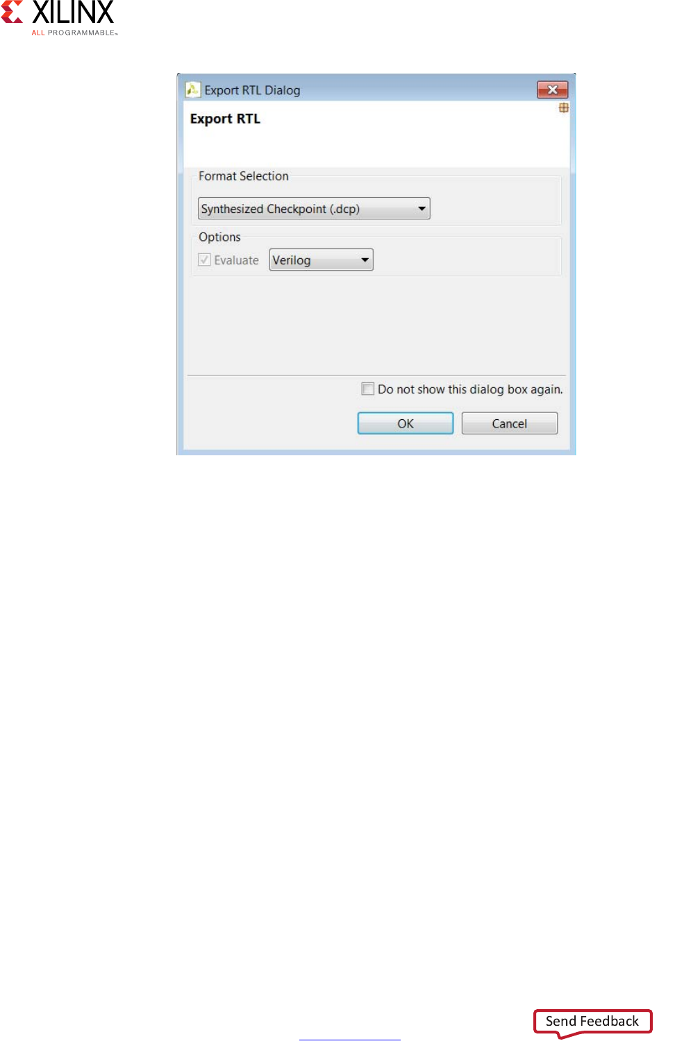
High-Level Synthesis 205
UG902 (v2017.1) April 5, 2017 www.xilinx.com
Chapter 1: High-Level Synthesis
When the design is packaged as a design checkpoint IP, the design is first synthesized
before being packaged.
Selecting OK generates the design checkpoint package. This package is written to the
<project_name>/<solution_name>/impl/ip directory. The design checkpoint files
can be used in a Vivado Design Suite project in the same manner as any other design
checkpoint.
X-Ref Target - Figure 1-77
Figure 1-77: Export RTL to Synthesized Checkpoint

High-Level Synthesis 206
UG902 (v2017.1) April 5, 2017 www.xilinx.com
Chapter 2
High-Level Synthesis C Libraries
Introduction to the Vivado HLS C Libraries
Vivado® HLS C libraries allow common hardware design constructs and function to be
easily modeled in C and synthesized to RTL. The following C libraries are provided with
Vivado HLS:
• Arbitrary Precision Data Types Library
•HLS Stream Library
•HLS Math Library
•HLS Video Library
• HLS IP Library
• HLS Linear Algebra Library
•HLS DSP Library
You can use each of the C libraries in your design by including the library header file. These
header files are located in the include directory in the Vivado HLS installation area.
IMPORTANT: The header files for the Vivado HLS C libraries do not have to be in the include path if the
design is used in Vivado HLS. The paths to the library header files are automatically added.
Arbitrary Precision Data Types Library
C-based native data types are on 8-bit boundaries (8, 16, 32, 64 bits). RTL buses
(corresponding to hardware) support arbitrary lengths. HLS needs a mechanism to allow
the specification of arbitrary precision bit-width and not rely on the artificial boundaries of
native C data types: if a 17-bit multiplier is required, you should not be forced to implement
this with a 32-bit multiplier.
Vivado HLS provides both integer and fixed-point arbitrary precision data types for C, C++
and supports the arbitrary precision data types which are part of SystemC.

High-Level Synthesis 207
UG902 (v2017.1) April 5, 2017 www.xilinx.com
Chapter 2: High-Level Synthesis C Libraries
The advantage of arbitrary precision data types is that they allow the C code to be updated
to use variables with smaller bit-widths and then for the C simulation to be re-executed to
validate the functionality remains identical or acceptable.
Using Arbitrary Precision Data Types
Vivado HLS provides arbitrary precision integer data types that manage the value of the
integer numbers within the boundaries of the specified width, as shown in the following
table.
Note: The header files define the arbitrary precision types are also provided with Vivado HLS as a
standalone package with the rights to use them in your own source code. The package,
xilinx_hls_lib_<release_number>.tgz is provided in the include directory in the Vivado
HLS installation area.
Arbitrary Integer Precision Types with C
For the C language, the header file ap_cint.h defines the arbitrary precision integer data
types [u]int.
Note: The package xilinx_hls_lib_<release_number>.tgz does not include the C arbitrary
precision types defined in ap_cint.h. These types cannot be used with standard C compilers, only
with the Vivado HLS cpcc compiler. More details on this are provided in Validating Arbitrary Precision
Types in C.
To use arbitrary precision integer data types in a C function:
• Add header file ap_cint.h to the source code.
• Change the bit types to intN for signed types or uintN for unsigned types, where N is
a bit-size from 1 to 1024.
The following example shows how the header file is added and two variables implemented
to use 9-bit integer and 10-bit unsigned integer types:
#include "ap_cint.h"
void foo_top (…) {
int9 var1; // 9-bit
uint10 var2; // 10-bit unsigned
Table 2-1: Integer Data Types
Language Integer Data Type Required Header
C [u]int<precision> (1024 bits) gcc #include “ap_cint.h”
C++ ap_[u]int<W> (1024 bits) #include “ap_int.h”
System C sc_[u]int<W> (64 bits)
sc_[u]bigint<W> (512 bits)
#include “systemc.h”

High-Level Synthesis 208
UG902 (v2017.1) April 5, 2017 www.xilinx.com
Chapter 2: High-Level Synthesis C Libraries
Arbitrary Integer Precision Types with C++
The header file ap_int.h defines the arbitrary precision integer data type for the C++
ap_[u]int data types listed in Table 2-2. To use arbitrary precision integer data types in a
C++ function:
• Add header file ap_int.h to the source code.
• Change the bit types to ap_int<N> for signed types or ap_uint<N> for unsigned
types, where N is a bit-size from 1 to 1024.
The following example shows how the header file is added and two variables implemented
to use 9-bit integer and 10-bit unsigned integer types:
#include "ap_int.h"
void foo_top (…) {
ap_int<9> var1; // 9-bit
ap_uint<10> var2; // 10-bit unsigned
Arbitrary Precision Integer Types with SystemC
The arbitrary precision types used by SystemC are defined in the systemc.h header file
that is required to be included in all SystemC designs. The header file includes the SystemC
sc_int<>, sc_uint<>, sc_bigint<> and sc_biguint<> types.
Arbitrary Precision Fixed-Point Data Types
In Vivado HLS, it is important to use fixed-point data types, because the behavior of the
C++/SystemC simulations performed using fixed-point data types match that of the
resulting hardware created by synthesis. This allows you to analyze the effects of
bit-accuracy, quantization, and overflow with fast C-level simulation.
Vivado HLS offers arbitrary precision fixed-point data types for use with C++ and SystemC
functions as shown in the following table.
Table 2-2: Fixed-Point Data Types
Language Fixed-Point Data Type Required Header
C -- Not Applicable -- -- Not Applicable --
C++ ap_[u]fixed<W,I,Q,O,N> #include “ap_fixed.h”
System C sc_[u]fixed<W,I,Q,O,N> #define SC_INCLUDE_FX
[#define SC_FX_EXCLUDE_OTHER]
#include “systemc.h”
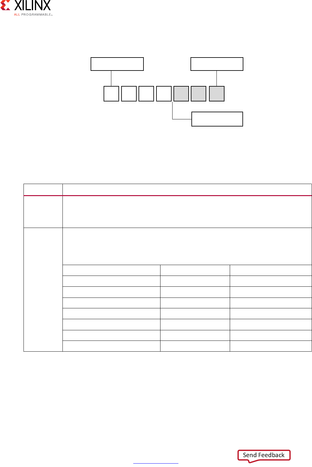
High-Level Synthesis 209
UG902 (v2017.1) April 5, 2017 www.xilinx.com
Chapter 2: High-Level Synthesis C Libraries
These data types manage the value of real (non-integer) numbers within the boundaries of
a specified total width and integer width, as shown in the following figure.
The following table provides a brief overview of operations supported by fixed-point types.
X-Ref Target - Figure 2-1
Figure 2-1: Fixed-Point Data Type
Table 2-3: Fixed-Point Identifier Summary
Identifier Description
W
I
Word length in bits
The number of bits used to represent the integer value (the number of bits above the
decimal point)
QQuantization mode
This dictates the behavior when greater precision is generated than can be defined by
smallest fractional bit in the variable used to store the result.
SystemC Types ap_fixed Types Description
SC_RND AP_RND Round to plus infinity
SC_RND_ZERO AP_RND_ZERO Round to zero
SC_RND_MIN_INF AP_RND_MIN_INF Round to minus infinity
SC_RND_INF AP_RND_INF Round to infinity
SC_RND_CONV AP_RND_CONV Convergent rounding
SC_TRN AP_TRN Truncation to minus infinity
SC_TRN_ZERO AP_TRN_ZERO Truncation to zero (default)
I-1 ... 1 0 -1 ... -B
MSB
Binary point
W = I+ B
LSB
;
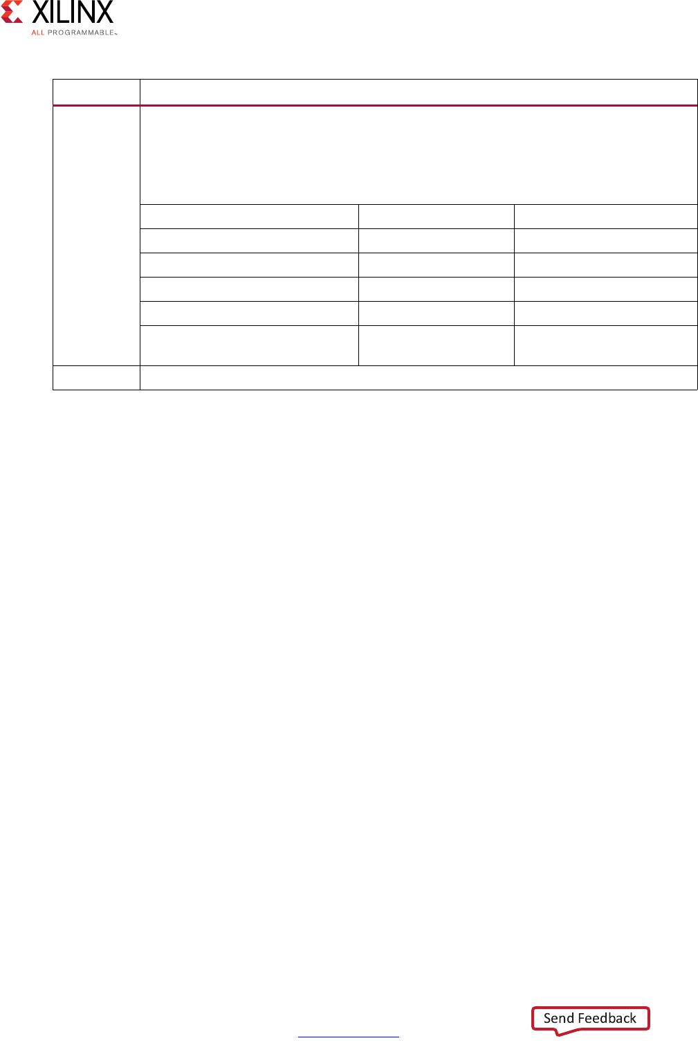
High-Level Synthesis 210
UG902 (v2017.1) April 5, 2017 www.xilinx.com
Chapter 2: High-Level Synthesis C Libraries
Example Using ap_fixed
In this example the Vivado HLS ap_fixed type is used to define an 18-bit variable with 6
bits representing the numbers above the decimal point and 12-bits representing the value
below the decimal point. The variable is specified as signed, the quantization mode is set to
round to plus infinity and the default wrap-around mode is used for overflow.
#include <ap_fixed.h>
...
ap_fixed<18,6,AP_RND > my_type;
...
Example Using sc_fixed
In this sc_fixed example a 22-bit variable is shown with 21 bits representing the numbers
above the decimal point: enabling only a minimum accuracy of 0.5. Rounding to zero is
used, such that any result less than 0.5 rounds to 0 and saturation is specified.
#define SC_INCLUDE_FX
#define SC_FX_EXCLUDE_OTHER
#include <systemc.h>
...
sc_fixed<22,21,SC_RND_ZERO,SC_SAT> my_type;
...
C Arbitrary Precision Integer Data Types
The native data types in C are on 8-bit boundaries (8, 16, 32 and 64 bits). RTL signals and
operations support arbitrary bit-lengths. Vivado HLS provides arbitrary precision data types
for C to allow variables and operations in the C code to be specified with any arbitrary
bit-widths: for example, 6-bit, 17-bit, and 234-bit, up to 1024 bits.
OOverflow mode.
This dictates the behavior when the result of an operation exceeds the maximum (or
minimum in the case of negative numbers) possible value that can be stored in the
variable used to store the result.
SystemC Types ap_fixed Types Description
SC_SAT AP_SAT Saturation
SC_SAT_ZERO AP_SAT_ZERO Saturation to zero
SC_SAT_SYM AP_SAT_SYM Symmetrical saturation
SC_WRAP AP_WRAP Wrap around (default)
SC_WRAP_SM AP_WRAP_SM Sign magnitude wrap
around
NThis defines the number of saturation bits in overflow wrap modes.
Table 2-3: Fixed-Point Identifier Summary (Cont’d)
Identifier Description

High-Level Synthesis 211
UG902 (v2017.1) April 5, 2017 www.xilinx.com
Chapter 2: High-Level Synthesis C Libraries
Vivado HLS also provides arbitrary precision data types in C++ and supports the arbitrary
precision data types that are part of SystemC. These types are discussed in the respective
C++ and SystemC coding.
Advantages of C Arbitrary Precision Data Types
The primary advantages of arbitrary precision data types are:
• Better quality hardware
If, for example, a 17-bit multiplier is required, you can use arbitrary precision types to
require exactly 17 bits in the calculation.
Without arbitrary precision data types, a multiplication such as 17 bits must be
implemented using 32-bit integer data types. This results in the multiplication being
implemented with multiple DSP48 components.
• Accurate C simulation and analysis
Arbitrary precision data types in the C code allows the C simulation to be executed using
accurate bit-widths and for the C simulation to validate the functionality (and accuracy)
of the algorithm before synthesis.
For the C language, the header file ap_cint.h defines the arbitrary precision integer data
types [u]int#W. For example:
•int8 represents an 8-bit signed integer data type.
•uint234 represents a 234-bit unsigned integer type.
The ap_cint.h file is located in the directory:
$HLS_ROOT/include
where
•$HLS_ROOT is the Vivado HLS installation directory.

High-Level Synthesis 212
UG902 (v2017.1) April 5, 2017 www.xilinx.com
Chapter 2: High-Level Synthesis C Libraries
The code shown in the following example is a repeat of the code shown in the Example 3-20
on basic arithmetic. In both examples, the data types in the top-level function to be
synthesized are specified as dinA_t, dinB_t, etc.
#include "apint_arith.h"
void apint_arith(din_A inA, din_B inB, din_C inC, din_D inD,
out_1 *out1, dout_2 *out2, dout_3 *out3, dout_4 *out4
) {
// Basic arithmetic operations
*out1 = inA * inB;
*out2 = inB + inA;
*out3 = inC / inA;
*out4 = inD % inA;
}
Example 2-1: Basic Arithmetic Revisited
The real difference between the two examples is in how the data types are defined. To use
arbitrary precision integer data types in a C function:
• Add header file ap_cint.h to the source code.
• Change the native C types to arbitrary precision types:
°intN
or
°uintN
where
-N is a bit size from 1 to 1024.
The data types are defined in the header apint_arith.h. See the following example
compared with Example 3-20:
• The input data types have been reduced to represent the maximum size of the real
input data. For example, 8-bit input inA is reduced to 6-bit input.

High-Level Synthesis 213
UG902 (v2017.1) April 5, 2017 www.xilinx.com
Chapter 2: High-Level Synthesis C Libraries
• The output types have been refined to be more accurate. For example, out2 (the sum
of inA and inB) needs to be only 13-bit, not 32-bit.
#include <stdio.h>
#include ap_cint.h
// Previous data types
//typedef char dinA_t;
//typedef short dinB_t;
//typedef int dinC_t;
//typedef long long dinD_t;
//typedef int dout1_t;
//typedef unsigned int dout2_t;
//typedef int32_t dout3_t;
//typedef int64_t dout4_t;
typedef int6 dinA_t;
typedef int12 dinB_t;
typedef int22 dinC_t;
typedef int33 dinD_t;
typedef int18 dout1_t;
typedef uint13 dout2_t;
typedef int22 dout3_t;
typedef int6 dout4_t;
void apint_arith(dinA_t inA,dinB_t inB,dinC_t inC,dinD_t inD,dout1_t
*out1,dout2_t *out2,dout3_t *out3,dout4_t *out4);
Example 2-2: Basic Arithmetic apint Types
Synthesizing the preceding example results in a design that is functionally identical to
Example 3-20 (given data in the range specified by the preceding example). The final RTL
design is smaller in area and has a faster clock speed, because smaller bit-widths result in
reduced logic.
The function must be compiled and validated before synthesis.
Validating Arbitrary Precision Types in C
To create arbitrary precision types, attributes are added to define the bit-sizes in file
ap_cint.h. Standard C compilers such as gcc compile the attributes used in the header
file, but they do not know what the attributes mean. This results in computations that do
not reflect the bit-accurate behavior of the code. For example, a 3-bit integer value with
binary representation 100 is treated by gcc (or any other third-party C compiler) as having
a decimal value 4 and not -4.
Note: This issue is only present when using C arbitrary precision types. There are no such issues with
C++ or SystemC arbitrary precision types.

High-Level Synthesis 214
UG902 (v2017.1) April 5, 2017 www.xilinx.com
Chapter 2: High-Level Synthesis C Libraries
Vivado HLS solves this issue by automatically using its own built-in C compiler apcc, when
it recognizes arbitrary precision C types are being used. This compiler is gcc compatible
but correctly interprets arbitrary precision types and arithmetic. You can invoke the apcc
compiler at the command prompt by replacing “gcc” by “apcc”.
$ apcc -o foo_top foo_top.c tb_foo_top.c
$ ./foo_top
When arbitrary precision types are used in C, the design can no longer be analyzed using
the Vivado HLS C debugger. If it is necessary to debug the design, Xilinx recommends one
of the following methodologies:
•Use the printf or fprintf functions to output the data values for analysis.
• Replace the arbitrary precision types with native C types (int, char, short, etc). This
approach helps debug the operation of the algorithm itself but does not help when you
must analyze the bit-accurate results of the algorithm.
• Change the C function to C++ and use C++ arbitrary precision types for which there
are no debugger limitations.
Integer Promotion
Take care when the result of arbitrary precision operations crosses the native 8, 16, 32 and
64-bit boundaries. In the following example, the intent is that two 18-bit values are
multiplied and the result stored in a 36-bit number:
#include "ap_cint.h"
int18 a,b;
int36 tmp;
tmp = a * b;
Integer promotion occurs when using this method. The result might not be as expected.
In integer promotion, the C compiler:
• Promotes the multiplication inputs to the native integer size (32-bit).
• Performs multiplication, which generates a 32-bit result.
• Assigns the result to the 36-bit variable tmp.
High-Level Synthesis 215
UG902 (v2017.1) April 5, 2017 www.xilinx.com
Chapter 2: High-Level Synthesis C Libraries
This results in the behavior and incorrect result shown in the following figure.
Because Vivado HLS produces the same results as C simulation, Vivado HLS creates
hardware in which a 32-bit multiplier result is sign-extended to a 36-bit result.
To overcome the integer promotion issue, cast operator inputs to the output size. The
following example shows where the inputs to the multiplier are cast to 36-bit value before
the multiplication. This results in the correct (expected) results during C simulation and the
expected 36-bit multiplication in the RTL.
#include "ap_cint.h"
typedef int18 din_t;
typedef int36 dout_t;
dout_t apint_promotion(din_t a,din_t b) {
dout_t tmp;
tmp = (dout_t)a * (dout_t)b;
return tmp;
}
Example 2-3: Cast to Avoid Integer Promotion
Casting to avoid integer promotion issue is required only when the result of an operation is
greater than the next native boundary (8, 16, 32, or 64). This behavior is more typical with
multipliers than with addition and subtraction operations.
There are no integer promotion issues when using C++ or SystemC arbitrary precision
types.
X-Ref Target - Figure 2-2
Figure 2-2: Integer Promotion
5HVXOWLQ+H[
5HVXOWಯSURPRWHGರWRELW
WPS
D
E
0XOWLSOLFDWLRQ5HVXOW
;

High-Level Synthesis 216
UG902 (v2017.1) April 5, 2017 www.xilinx.com
Chapter 2: High-Level Synthesis C Libraries
C Arbitrary Precision Integer Types: Reference Information
The information in C Arbitrary Precision Types in Chapter 4 provides information on:
• Techniques for assigning constant and initialization values to arbitrary precision
integers (including values greater than 64-bit).
• A description of Vivado HLS helper functions, such as printing, concatenating,
bit-slicing and range selection functions.
• A description of operator behavior, including a description of shift operations (a
negative shift values, results in a shift in the opposite direction).
C++ Arbitrary Precision Integer Types
The native data types in C++ are on 8-bit boundaries (8, 16, 32 and 64 bits). RTL signals and
operations support arbitrary bit-lengths.
Vivado HLS provides arbitrary precision data types for C++ to allow variables and
operations in the C++ code to be specified with any arbitrary bit-widths: 6-bit, 17-bit,
234-bit, up to 1024 bits.
TIP: The default maximum width allowed is 1024 bits. You can override this default by defining the
macro AP_INT_MAX_W with a positive integer value less than or equal to 32768 before inclusion of the
ap_int.h header file.
C++ supports use of the arbitrary precision types defined in the SystemC standard. Include
the SystemC header file systemc.h, and use SystemC data types. For more information on
SystemC types, see SystemC Synthesis in Chapter 3.
Arbitrary precision data types have are two primary advantages over the native C++ types:
• Better quality hardware: If for example, a 17-bit multiplier is required, arbitrary
precision types can specify that exactly 17-bit are used in the calculation.
Without arbitrary precision data types, such a multiplication (17-bit) must be
implemented using 32-bit integer data types and result in the multiplication being
implemented with multiple DSP48 components.
• Accurate C++ simulation/analysis: Arbitrary precision data types in the C++ code
allows the C++ simulation to be performed using accurate bit-widths and for the C++
simulation to validate the functionality (and accuracy) of the algorithm before
synthesis.

High-Level Synthesis 217
UG902 (v2017.1) April 5, 2017 www.xilinx.com
Chapter 2: High-Level Synthesis C Libraries
The arbitrary precision types in C++ have none of the disadvantages of those in C:
• C++ arbitrary types can be compiled with standard C++ compilers (there is no C++
equivalent of apcc, as discussed in Validating Arbitrary Precision Types in C).
• C++ arbitrary precision types do not suffer from Integer Promotion Issues.
It is not uncommon for users to change a file extension from .c to .cpp so the file can be
compiled as C++, where neither of these issues are present.
For the C++ language, the header file ap_int.h defines the arbitrary precision integer
data types ap_(u)int<W>. For example, ap_int<8> represents an 8-bit signed integer
data type and ap_uint<234> represents a 234-bit unsigned integer type.
The ap_int.h file is located in the directory $HLS_ROOT/include, where $HLS_ROOT is the
Vivado HLS installation directory.
The code shown in the following example, is a repeat of the code shown in the earlier
example on basic arithmetic (Example 3-20 and again in Example 2-1). In this example the
data types in the top-level function to be synthesized are specified as dinA_t, dinB_t ...
#include "cpp_ap_int_arith.h"
void cpp_ap_int_arith(din_A inA, din_B inB, din_C inC, din_D inD,
dout_1 *out1, dout_2 *out2, dout_3 *out3, dout_4 *out4
) {
// Basic arithmetic operations
*out1 = inA * inB;
*out2 = inB + inA;
*out3 = inC / inA;
*out4 = inD % inA;
}
Example 2-4: Basic Arithmetic Revisited with C++ Types
In this latest update to this example, the C++ arbitrary precision types are used:
• Add header file ap_int.h to the source code.
• Change the native C++ types to arbitrary precision types ap_int<N> or ap_uint<N>,
where N is a bit-size from 1 to 1024 (as noted above, this can be extended to 32K-bits is
required).
The data types are defined in the header cpp_ap_int_arith.h as shown in Example 2-2.
Compared with Example 3-20, the input data types have simply been reduced to represent
the maximum size of the real input data (for example, 8-bit input inA is reduced to 6-bit
input). The output types have been refined to be more accurate, for example, out2, the
sum of inA and inB, need only be 13-bit and not 32-bit.

High-Level Synthesis 218
UG902 (v2017.1) April 5, 2017 www.xilinx.com
Chapter 2: High-Level Synthesis C Libraries
#ifndef _CPP_AP_INT_ARITH_H_
#define _CPP_AP_INT_ARITH_H_
#include <stdio.h>
#include "ap_int.h"
#define N 9
// Old data types
//typedef char dinA_t;
//typedef short dinB_t;
//typedef int dinC_t;
//typedef long long dinD_t;
//typedef int dout1_t;
//typedef unsigned int dout2_t;
//typedef int32_t dout3_t;
//typedef int64_t dout4_t;
typedef ap_int<6> dinA_t;
typedef ap_int<12> dinB_t;
typedef ap_int<22> dinC_t;
typedef ap_int<33> dinD_t;
typedef ap_int<18> dout1_t;
typedef ap_uint<13> dout2_t;
typedef ap_int<22> dout3_t;
typedef ap_int<6> dout4_t;
void cpp_ap_int_arith(dinA_t inA,dinB_t inB,dinC_t inC,dinD_t inD,dout1_t
*out1,dout2_t *out2,dout3_t *out3,dout4_t *out4);
#endif
Example 2-5: Basic Arithmetic with C++ Arbitrary Precision Types
If Example 2-4 is synthesized, it results in a design that is functionally identical to
Example 3-20 and Example 2-2. It keeps the test bench as similar as possible to
Example 2-2, rather than use the C++ cout operator to output the results to a file, the
built-in ap_int method .to_int() is used to convert the ap_int results to integer types
used with the standard fprintf function.
fprintf(fp, %d*%d=%d; %d+%d=%d; %d/%d=%d; %d mod %d=%d;\n,
inA.to_int(), inB.to_int(), out1.to_int(),
inB.to_int(), inA.to_int(), out2.to_int(),
inC.to_int(), inA.to_int(), out3.to_int(),
inD.to_int(), inA.to_int(), out4.to_int());
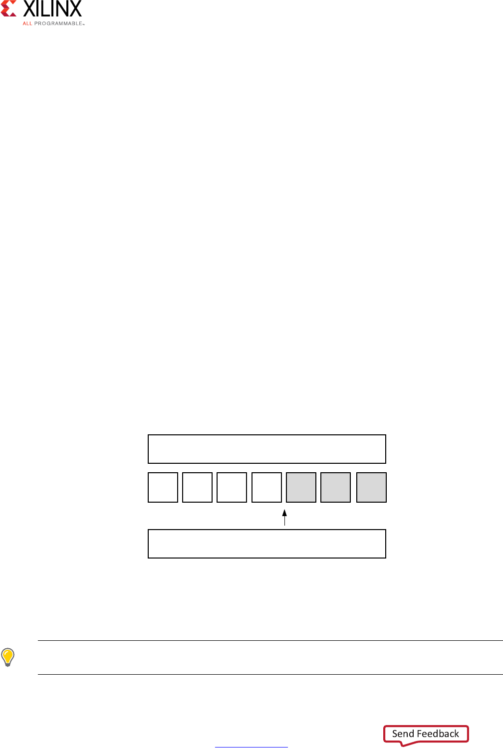
High-Level Synthesis 219
UG902 (v2017.1) April 5, 2017 www.xilinx.com
Chapter 2: High-Level Synthesis C Libraries
C++ Arbitrary Precision Integer Types: Reference Information
For comprehensive information on the methods, synthesis behavior, and all aspects of using
the ap_(u)int<N> arbitrary precision data types, see C++ Arbitrary Precision Types in
Chapter 4. This section includes:
• Techniques for assigning constant and initialization values to arbitrary precision
integers (including values greater than 1024-bit).
• A description of Vivado HLS helper methods, such as printing, concatenating,
bit-slicing and range selection functions.
• A description of operator behavior, including a description of shift operations (a
negative shift values, results in a shift in the opposite direction).
C++ Arbitrary Precision Fixed-Point Types
C++ functions can take advantage of the arbitrary precision fixed-point types included with
Vivado HLS. The following figure summarizes the basic features of these fixed-point types:
• The word can be signed (ap_fixed) or unsigned (ap_ufixed).
• A word with of any arbitrary size W can be defined.
• The number of places above the decimal point I, also defines the number of decimal
places in the word, W-I (represented by B in the following figure).
• The type of rounding or quantization (Q) can be selected.
• The overflow behavior (O and N) can be selected.
The arbitrary precision fixed-point types can be used when header file ap_fixed.h is
included in the code.
TIP: Arbitrary precision fixed-point types use more memory during C simulation. If using very large
arrays of ap_[u]fixed types, refer to the discussion of C simulation in Arrays in Chapter 3.
X-Ref Target - Figure 2-3
Figure 2-3: Arbitrary Precision Fixed-Point Types
, %
DSB>X@IL[HG:,421!
%LQDU\SRLQW: ,%
;

High-Level Synthesis 220
UG902 (v2017.1) April 5, 2017 www.xilinx.com
Chapter 2: High-Level Synthesis C Libraries
The advantages of using fixed-point types are:
• They allow fractional number to be easily represented.
• When variables have a different number of integer and decimal place bits, the
alignment of the decimal point is handled.
• There are numerous options to handle how rounding should happen: when there are
too few decimal bits to represent the precision of the result.
• There are numerous options to handle how variables should overflow: when the result
is greater than the number of integer bits can represent.
These attributes are summarized by examining the code in Example 2-6. First, the header
file ap_fixed.h is included. The ap_fixed types are then defined using the typedef
statement:
• A 10-bit input: 8-bit integer value with 2 decimal places.
• A 6-bit input: 3-bit integer value with 3 decimal places.
• A 22-bit variable for the accumulation: 17-bit integer value with 5 decimal places.
• A 36-bit variable for the result: 30-bit integer value with 6 decimal places.
The function contains no code to manage the alignment of the decimal point after
operations are performed. The alignment is done automatically.
#include "ap_fixed.h"
typedef ap_ufixed<10,8, AP_RND, AP_SAT> din1_t;
typedef ap_fixed<6,3, AP_RND, AP_WRAP> din2_t;
typedef ap_fixed<22,17, AP_TRN, AP_SAT> dint_t;
typedef ap_fixed<36,30> dout_t;
dout_t cpp_ap_fixed(din1_t d_in1, din2_t d_in2) {
static dint_t sum;
sum += d_in1;
return sum * d_in2;
}
Example 2-6: ap_fixed Type Example
The following table shows the quantization and overflow modes. For detailed information,
see C++ Arbitrary Precision Fixed-Point Types in Chapter 4.
TIP: Quantization and overflow modes that do more than the default behavior of standard hardware
arithmetic (wrap and truncate) result in operators with more associated hardware. It costs logic (LUTs)
to implement the more advanced modes, such as round to minus infinity or saturate symmetrically.

High-Level Synthesis 221
UG902 (v2017.1) April 5, 2017 www.xilinx.com
Chapter 2: High-Level Synthesis C Libraries
Using ap_(u)fixed types, the C++ simulation is bit accurate. Fast simulation can validate
the algorithm and its accuracy. After synthesis, the RTL exhibits the identical bit-accurate
behavior.
Arbitrary precision fixed-point types can be freely assigned literal values in the code. See
shown the test bench (Example 2-7) used with Example 2-6, in which the values of in1 and
in2 are declared and assigned constant values.
When assigning literal values involving operators, the literal values must first be cast to
ap_(u)fixed types. Otherwise, the C compiler and Vivado HLS interpret the literal as an
integer or float/double type and may fail to find a suitable operator. As shown in the
following example, in the assignment of in1 = in1 + din1_t(0.25), the literal 0.25 is
cast to an ap_fixed type.
Table 2-4: Fixed-Point Identifier Summary
Identifier Description
WWord length in bits
IThe number of bits used to represent the integer value (the number of bits above the
decimal point)
QQuantization mode dictates the behavior when greater precision is generated than can
be defined by smallest fractional bit in the variable used to store the result.
Mode Description
AP_RND Rounding to plus infinity
AP_RND_ZERO Rounding to zero
AP_RND_MIN_INF Rounding to minus infinity
AP_RND_INF Rounding to infinity
AP_RND_CONV Convergent rounding
AP_TRN Truncation to minus infinity
AP_TRN_ZERO Truncation to zero (default)
OOverflow mode dictates the behavior when more bits are generated than the variable to
store the result contains.
Mode Description
AP_SAT Saturation
AP_SAT_ZERO Saturation to zero
AP_SAT_SYM Symmetrical saturation
AP_WRAP Wrap around (default)
AP_WRAP_SM Sign magnitude wrap around
NThe number of saturation bits in wrap modes.

High-Level Synthesis 222
UG902 (v2017.1) April 5, 2017 www.xilinx.com
Chapter 2: High-Level Synthesis C Libraries
#include <cmath>
#include <fstream>
#include <iostream>
#include <iomanip>
#include <cstdlib>
using namespace std;
#include "ap_fixed.h"
typedef ap_ufixed<10,8, AP_RND, AP_SAT> din1_t;
typedef ap_fixed<6,3, AP_RND, AP_WRAP> din2_t;
typedef ap_fixed<22,17, AP_TRN, AP_SAT> dint_t;
typedef ap_fixed<36,30> dout_t;
dout_t cpp_ap_fixed(din1_t d_in1, din2_t d_in2);
int main()
{
ofstream result;
din1_t in1 = 0.25;
din2_t in2 = 2.125;
dout_t output;
int retval=0;
result.open(result.dat);
// Persistent manipulators
result << right << fixed << setbase(10) << setprecision(15);
for (int i = 0; i <= 250; i++)
{
output = cpp_ap_fixed(in1,in2);
result << setw(10) << i;
result << setw(20) << in1;
result << setw(20) << in2;
result << setw(20) << output;
result << endl;
in1 = in1 + din1_t(0.25);
in2 = in2 - din2_t(0.125);
}
result.close();
// Compare the results file with the golden results
retval = system(diff --brief -w result.dat result.golden.dat);
if (retval != 0) {
printf(Test failed !!!\n);
retval=1;
} else {
printf(Test passed !\n);
}
// Return 0 if the test passes
return retval;
}
Example 2-7: ap_fixed Type Test Bench Coding Example

High-Level Synthesis 223
UG902 (v2017.1) April 5, 2017 www.xilinx.com
Chapter 2: High-Level Synthesis C Libraries
C++ Arbitrary Precision Fixed-Point Types: Reference Information
For comprehensive information on the methods, synthesis behavior, and all aspects of using
the ap_(u)fixed<N> arbitrary precision fixed-point data types, see C++ Arbitrary
Precision Fixed-Point Types in Chapter 4. This section includes:
• Techniques for assigning constant and initialization values to arbitrary precision
integers (including values greater than 1024-bit).
• A detailed description of the overflow and saturation modes.
• A description of Vivado HLS helper methods, such as printing, concatenating,
bit-slicing and range selection functions.
• A description of operator behavior, including a description of shift operations (a
negative shift values, results in a shift in the opposite direction).
HLS Stream Library
Streaming data is a type of data transfer in which data samples are sent in sequential order
starting from the first sample. Streaming requires no address management.
Modeling designs that use streaming data can be difficult in C. As discussed in Multi-Access
Pointer Interfaces: Streaming Data in Chapter 3, the approach of using pointers to perform
multiple read and/or write accesses can introduce issues, because there are implications for
the type qualifier and how the test bench is constructed.
Vivado HLS provides a C++ template class hls::stream<> for modeling streaming data
structures. The streams implemented with the hls::stream<> class have the following
attributes.
•In the C code, an hls::stream<> behaves like a FIFO of infinite depth. There is no
requirement to define the size of an hls::stream<>.
• They are read from and written to sequentially. That is, after data is read from an
hls::stream<>, it cannot be read again.
•An hls::stream<> on the top-level interface is by default implemented with an
ap_fifo interface.
•An hls::stream<> internal to the design is implemented as a FIFO with a depth of 1.
The optimization directive STREAM is used to change this default size.
High-Level Synthesis 224
UG902 (v2017.1) April 5, 2017 www.xilinx.com
Chapter 2: High-Level Synthesis C Libraries
This section shows how the hls::stream<> class can more easily model designs with
streaming data. The topics in this section provide:
• An overview of modeling with streams and the RTL implementation of streams.
• Rules for global stream variables.
•How to use streams.
• Blocking reads and writes.
• Non-Blocking Reads and writes.
• Controlling the FIFO depth.
Note: The hls::stream class should always be passed between functions as a C++ reference
argument. For example, &my_stream.
IMPORTANT: The hls::stream class is only used in C++ designs.
C Modeling and RTL Implementation
Streams are modeled as an infinite queue in software (and in the test bench during RTL
co-simulation). There is no need to specify any depth to simulate streams in C++. Streams
can be used inside functions and on the interface to functions. Internal streams may be
passed as function parameters.
Streams can be used only in C++ based designs. Each hls::stream<> object must be
written by a single process and read by a single process.
If an hls::stream is used on the top-level interface, it is by default implemented in the
RTL as a FIFO interface (ap_fifo) but may be optionally implemented as a handshake
interface (ap_hs) or an AXI-Stream interface (axis).
If an hls::steam is used inside the design function and synthesized into hardware, it is
implemented as a FIFO with a default depth of 1. In some cases, such as when interpolation
is used, the depth of the FIFO might have to be increased to ensure the FIFO can hold all the
elements produced by the hardware. Failure to ensure the FIFO is large enough to hold all
the data samples generated by the hardware can result in a stall in the design (seen in C/RTL
co-simulation and in the hardware implementation). The depth of the FIFO can be adjusted
using the STREAM directive with the depth option. An example of this is provided in the
example design hls_stream, as shown in Table 1-5.
IMPORTANT: Ensure hls::stream variables are correctly sized when used in the default
non-DATAFLOW regions.
If an hls::stream is used to transfer data between tasks (sub-functions or loops), you
should immediately consider implementing the tasks in a DATAFLOW region where data
streams from one task to the next. The default (non-DATAFLOW) behavior is to complete

High-Level Synthesis 225
UG902 (v2017.1) April 5, 2017 www.xilinx.com
Chapter 2: High-Level Synthesis C Libraries
each task before starting the next task, in which case the FIFOs used to implement the
hls::stream variables must be sized to ensure they are large enough to hold all the data
samples generated by the producer task. Failure to increase the size of the hls::stream
variables results in the error below:
ERROR: [XFORM 203-733] An internal stream xxxx.xxxx.V.user.V' with default size is
used in a non-dataflow region, which may result in deadlock. Please consider to
resize the stream using the directive 'set_directive_stream' or the 'HLS stream'
pragma.
This error informs you that in a non-DATAFLOW region (the default FIFOs of depth of 1) may
not be large enough to hold all the data samples written to the FIFO by the producer task.
Global and Local Streams
Streams may be defined either locally or globally. Local streams are always implemented as
internal FIFOs. Global streams can be implemented as internal FIFOs or ports:
• Globally-defined streams that are only read from, or only written to, are inferred as
external ports of the top-level RTL block.
• Globally-defined streams that are both read from and written to (in the hierarchy below
the top-level function) are implemented as internal FIFOs.
Streams defined in the global scope follow the same rules as any other global variables. For
more information on the synthesis of global variables, see Data Types and Bit-Widths in
Chapter 1.
Using HLS Streams
To use hls::stream<> objects, include the header file hls_stream.h. Streaming data
objects are defined by specifying the type and variable name. In this example, a 128-bit
unsigned integer type is defined and used to create a stream variable called
my_wide_stream.
#include "ap_int.h"
#include "hls_stream.h"
typedef ap_uint<128> uint128_t; // 128-bit user defined type
hls::stream<uint128_t> my_wide_stream; // A stream declaration
Streams must use scoped naming. Xilinx recommends using the scoped hls:: naming
shown in the example above. However, if you want to use the hls namespace, you can
rewrite the preceding example as:
#include <ap_int.h>
#include <hls_stream.h>
using namespace hls;
typedef ap_uint<128> uint128_t; // 128-bit user defined type
stream<uint128_t> my_wide_stream; // hls:: no longer required

High-Level Synthesis 226
UG902 (v2017.1) April 5, 2017 www.xilinx.com
Chapter 2: High-Level Synthesis C Libraries
Given a stream specified as hls::stream<T>, the type T may be:
• Any C++ native data type
• A Vivado HLS arbitrary precision type (for example, ap_int<>, ap_ufixed<>)
• A user-defined struct containing either of the above types
Note: General user-defined classes (or structures) that contain methods (member functions) should
not be used as the type (T) for a stream variable.
Streams may be optional named. Providing a name for the stream allows the name to be
used in reporting. For example, Vivado HLS automatically checks to ensure all elements
from an input stream are read during simulation. Given the following two streams:
stream<uint8_t> bytestr_in1;
stream<uint8_t> bytestr_in2("input_stream2");
Any warning on elements left in the streams are reported as follows, where it is clear which
message relates to bytetr_in2:
WARNING: Hls::stream 'hls::stream<unsigned char>.1' contains leftover data, which
may result in RTL simulation hanging.
WARNING: Hls::stream 'input_stream2' contains leftover data, which may result in RTL
simulation hanging.
When streams are passed into and out of functions, they must be passed-by-reference as in
the following example:
void stream_function (
hls::stream<uint8_t> &strm_out,
hls::stream<uint8_t> &strm_in,
uint16_t strm_len
)
Vivado HLS supports both blocking and non-blocking access methods.
• Non-blocking accesses can be implemented only as FIFO interfaces.
• Streaming ports that are implemented as ap_fifo ports and that are defined with an
AXI4-Stream resource must not use non-blocking accesses.
A complete design example using streams is provided in the Vivado HLS examples. Refer to
the hls_stream example in the design examples available from the GUI welcome screen.
Blocking Reads and Writes
The basic accesses to an hls::stream<> object are blocking reads and writes. These are
accomplished using class methods. These methods stall (block) execution if a read is
attempted on an empty stream FIFO, a write is attempted to a full stream FIFO, or until a full
handshake is accomplished for a stream mapped to an ap_hs interface protocol.

High-Level Synthesis 227
UG902 (v2017.1) April 5, 2017 www.xilinx.com
Chapter 2: High-Level Synthesis C Libraries
A stall can be observed in C/RTL co-simulation as the continued execution of the simulator
without any progress in the transactions. The following shows a classic example of a stall
situation, where the RTL simulation time keeps increasing, but there is no progress in the
inter or intra transactions:
// RTL Simulation : "Inter-Transaction Progress" ["Intra-Transaction Progress"] @
"Simulation Time"
///////////////////////////////////////////////////////////////////////////////////
// RTL Simulation : 0 / 1 [0.00%] @ "110000"
// RTL Simulation : 0 / 1 [0.00%] @ "202000"
// RTL Simulation : 0 / 1 [0.00%] @ "404000"
Blocking Write Methods
In this example, the value of variable src_var is pushed into the stream.
// Usage of void write(const T & wdata)
hls::stream<int> my_stream;
int src_var = 42;
my_stream.write(src_var);
The << operator is overloaded such that it may be used in a similar fashion to the stream
insertion operators for C++ stream (for example, iostreams and filestreams). The
hls::stream<> object to be written to is supplied as the left-hand side argument and the
value to be written as the right-hand side.
// Usage of void operator << (T & wdata)
hls::stream<int> my_stream;
int src_var = 42;
my_stream << src_var;
Blocking Read Methods
This method reads from the head of the stream and assigns the values to the variable
dst_var.
// Usage of void read(T &rdata)
hls::stream<int> my_stream;
int dst_var;
my_stream.read(dst_var);

High-Level Synthesis 228
UG902 (v2017.1) April 5, 2017 www.xilinx.com
Chapter 2: High-Level Synthesis C Libraries
Alternatively, the next object in the stream can be read by assigning (using for example =,
+=) the stream to an object on the left-hand side:
// Usage of T read(void)
hls::stream<int> my_stream;
int dst_var = my_stream.read();
The '>>' operator is overloaded to allow use similar to the stream extraction operator for
C++ stream (for example, iostreams and filestreams). The hls::stream is supplied as the
LHS argument and the destination variable the RHS.
// Usage of void operator >> (T & rdata)
hls::stream<int> my_stream;
int dst_var;
my_stream >> dst_var;
Non-Blocking Reads and Writes
Non-blocking write and read methods are also provided. These allow execution to continue
even when a read is attempted on an empty stream or a write to a full stream.
These methods return a Boolean value indicating the status of the access (true if
successful, false otherwise). Additional methods are included for testing the status of an
hls::stream<> stream.
IMPORTANT: Non-blocking behavior is only supported on interfaces using the ap_fifo protocol.
More specifically, the AXI-Stream standard and the Xilinx ap_hs IO protocol do not support
non-blocking accesses.
During C simulation, streams have an infinite size. It is therefore not possible to validate
with C simulation if the stream is full. These methods can be verified only during RTL
simulation when the FIFO sizes are defined (either the default size of 1, or an arbitrary size
defined with the STREAM directive).
IMPORTANT: If the design is specified to use the block-level I/O protocol ap_ctrl_none and the design
contains any hls::stream variables that employ non-blocking behavior, C/RTL co-simulation is not
guaranteed to complete.

High-Level Synthesis 229
UG902 (v2017.1) April 5, 2017 www.xilinx.com
Chapter 2: High-Level Synthesis C Libraries
Non-Blocking Writes
This method attempts to push variable src_var into the stream my_stream, returning a
boolean true if successful. Otherwise, false is returned and the queue is unaffected.
// Usage of void write_nb(const T & wdata)
hls::stream<int> my_stream;
int src_var = 42;
if (my_stream.write_nb(src_var)) {
// Perform standard operations
...
} else {
// Write did not occur
return;
}
Fullness Test
bool full(void)
Returns true, if and only if the hls::stream<> object is full.
// Usage of bool full(void)
hls::stream<int> my_stream;
int src_var = 42;
bool stream_full;
stream_full = my_stream.full();
Non-Blocking Read
bool read_nb(T & rdata)
This method attempts to read a value from the stream, returning true if successful.
Otherwise, false is returned and the queue is unaffected.
// Usage of void read_nb(const T & wdata)
hls::stream<int> my_stream;
int dst_var;
if (my_stream.read_nb(dst_var)) {
// Perform standard operations
...
} else {
// Read did not occur
return;
}

High-Level Synthesis 230
UG902 (v2017.1) April 5, 2017 www.xilinx.com
Chapter 2: High-Level Synthesis C Libraries
Emptiness Test
bool empty(void)
Returns true if the hls::stream<> is empty.
// Usage of bool empty(void)
hls::stream<int> my_stream;
int dst_var;
bool stream_empty;
stream_empty = my_stream.empty();
The following example shows how a combination of non-blocking accesses and full/empty
tests can provide error handling functionality when the RTL FIFOs are full or empty:
#include "hls_stream.h"
using namespace hls;
typedef struct {
short data;
bool valid;
bool invert;
} input_interface;
bool invert(stream<input_interface>& in_data_1,
stream<input_interface>& in_data_2,
stream<short>& output
) {
input_interface in;
bool full_n;
// Read an input value or return
if (!in_data_1.read_nb(in))
if (!in_data_2.read_nb(in))
return false;
// If the valid data is written, return not-full (full_n) as true
if (in.valid) {
if (in.invert)
full_n = output.write_nb(~in.data);
else
full_n = output.write_nb(in.data);
}
return full_n;
}
Controlling the RTL FIFO Depth
For most designs using streaming data, the default RTL FIFO depth of 1 is sufficient.
Streaming data is generally processed one sample at a time.

High-Level Synthesis 231
UG902 (v2017.1) April 5, 2017 www.xilinx.com
Chapter 2: High-Level Synthesis C Libraries
For multirate designs in which the implementation requires a FIFO with a depth greater than
1, you must determine (and set using the STREAM directive) the depth necessary for the RTL
simulation to complete. If the FIFO depth is insufficient, RTL co-simulation stalls.
Because stream objects cannot be viewed in the GUI directives pane, the STREAM directive
cannot be applied directly in that pane.
Right-click the function in which an hls::stream<> object is declared (or is used, or exists
in the argument list) to:
• Select the STREAM directive.
•Populate the variable field manually with name of the stream variable.
Alternatively, you can:
• Specify the STREAM directive manually in the directives.tcl file, or
• Add it as a pragma in source.
C/RTL Co-Simulation Support
The Vivado HLS C/RTL co-simulation feature does not support structures or classes
containing hls::stream<> members in the top-level interface. Vivado HLS supports
these structures or classes for synthesis.
typedef struct {
hls::stream<uint8_t> a;
hls::stream<uint16_t> b;
} strm_strct_t;
void dut_top(strm_strct_t indata, strm_strct_t outdata) { … }
These restrictions apply to both top-level function arguments and globally declared
objects. If structs of streams are used for synthesis, the design must be verified using an
external RTL simulator and user-created HDL test bench. There are no such restrictions on
hls::stream<> objects with strictly internal linkage.
HLS Math Library
The Vivado HLS Math Library (hls_math.h) provides support for the synthesis of the
standard C (math.h) and C++ (cmath.h) libraries and is automatically used to specify the
math operations during synthesis. The support includes floating point (single-precision,
double-precision and half-precision) for all functions and fixed-point support for some
functions.

High-Level Synthesis 232
UG902 (v2017.1) April 5, 2017 www.xilinx.com
Chapter 2: High-Level Synthesis C Libraries
The hls_math.h library can optionally be used in the C source in place of the standard C
math library. The difference between using the standard C math library and using the
hls_math.h math library in the C source is the accuracy of the results reported in C
simulation and C/RTL co-simulation.
HLS Math Library Accuracy
The HLS math functions are implemented as synthesizable bit-approximate functions from
the hls_math.h library. Bit-approximate HLS math library functions do not provide the
same accuracy as the standard C function. To achieve the desired result, the bit-approximate
implementation may use a different underlying algorithm than the standard C math library
version. The accuracy of the function is specified in terms of ULP (Unit of Least Precision).
This difference in accuracy has implications for both C simulation and C/RTL co-simulation.
The ULP difference is typically in the range of 1-4 ULP.
• If the standard C math library is used in the C source code, there may be a difference
between the C simulation and the C/RTL co-simulation due to the fact that some
functions exhibit a ULP difference from the standard C math library.
• If the HLS math library is used in the C source code, there will be no difference between
the C simulation and the C/RTL co-simulation. A C simulation using the HLS math
library, may however differ from a C simulation using the standard C math library.
The Verification and Math Functions section below details a number of options for verifying
the synthesized design will perform with the required accuracy.
In addition, the following seven functions might show some differences, depending on the
C standard used to compile and run the C simulation:
•copysign
• fpclassify
•isinf
• isfinite
•isnan
• isnormal
• signbit
C90 mode
Only isinf, isnan, and copysign are usually provided by the system header files, and
they operate on doubles. In particular, copysign always returns a double result. This might
result in unexpected results after synthesis if it must be returned to a float, because a
double-to-float conversion block is introduced into the hardware.

High-Level Synthesis 233
UG902 (v2017.1) April 5, 2017 www.xilinx.com
Chapter 2: High-Level Synthesis C Libraries
C99 mode (-std=c99)
All seven functions are usually provided under the expectation that the system header files
will redirect them to __isnan(double) and __isnan(float). The usual GCC header
files do not redirect isnormal, but implement it in terms of fpclassify.
C++ Using math.h
All seven are provided by the system header files, and they operate on doubles.
copysign always returns a double result. This might cause unexpected results after
synthesis if it must be returned to a float, because a double-to-float conversion block is
introduced into the hardware.
C++ Using cmath
Similar to C99 mode(-std=c99), except that:
°The system header files are usually different.
°The functions are properly overloaded for:
-float(). snan(double)
-isinf(double)
copysign and copysignf are handled as built-ins even when using namespace std;.
C++ Using cmath and namespace std
No issues. Xilinx recommends using the following for best results:
•-std=c99 for C
•-fno-builtin for C and C++
Note: To specify the C compile options, such as -std=c99, use the Tcl command add_files with
the -cflags option. Alternatively, use the Edit CFLAGs button in the Project Settings dialog box.
The HLS Math Library
The following functions are provided in the HLS math library. Each function supports
half-precision (type half), single-precision (type float) and double precision (type
double).
IMPORTANT: For each function func listed below, there is also an associated half-precision
only function named half_func and single-precision only function named funcf
provided in the library.

High-Level Synthesis 234
UG902 (v2017.1) April 5, 2017 www.xilinx.com
Chapter 2: High-Level Synthesis C Libraries
When mixing half-precision, single-precision and double-precision data types, review
Common Synthesis Errors to prevent introducing type-conversion hardware in the final
FPGA implementation.
Trigonometric Functions
Hyperbolic Functions
Exponential Functions
Logarithmic Functions
Power Functions
Error Functions
Gamma Functions
acos acospi asin asinpi
atan atan2 atan2pi asinpi
cos cospi sin sincos
sinpi tan tanpi
acosh asinh atanh cosh
sinh tanh
exp exp10 exp2 expm1
frexp ldexp modf scalbln
scalbn
ilogb log log10 log1p
log2 logb
cbrt hypot pow pown
powr rootn rsqrt sqrt
erf erfc
lgamma lgamma_r tgamma

High-Level Synthesis 235
UG902 (v2017.1) April 5, 2017 www.xilinx.com
Chapter 2: High-Level Synthesis C Libraries
Rounding Functions
Remainder Functions
Floating-point
Difference Functions
Other Functions
Classification Functions
Comparison Functions
Relational Functions
ceil floor llrint llround
lrint lround nearbyint rint
round trunc
fmod remainder remquo
copysign nan nextafter nexttoward
fdim fmax fmin maxmag
minmag
abs divide fabs fma
fract mad recip
fpclassify isfinite isinf isnan
isnormal signbit
isgreater isgreaterequal isless islessequal
islessgreater isunordered

High-Level Synthesis 236
UG902 (v2017.1) April 5, 2017 www.xilinx.com
Chapter 2: High-Level Synthesis C Libraries
Fixed-Point Math Functions
Fixed-point implementations are also provided for the following math functions:
Trigonometric Functions
These are supported for ap_fixed data types with bit-width specification
ap_fixed<W,2> where W<=32:
Exponential Functions
These are supported for ap_fixed data types with bit-width specifications
ap_fixed<16,8> and ap_fixed<8,4>:
Power Functions
These are supported for ap_fixed data types with bit-width specification
ap_fixed<W,I> where W<=32 :
The fixed-point type provides a slightly-less accurate version of the function value, but a
smaller and faster RTL implementation.
The methodology for implementing a math function with a fixed-point data types is:
1. Determine if a fixed-point implementation is supported.
2. Update the math functions to use ap_fixed types.
3. Perform C simulation to validate the design still operates with the required precision.
The C simulation is performed using the same bit-accurate types as the RTL
implementation.
4. Synthesize the design.
all any bitselect isequal
isnotequal isordered select
cos cospi sin sinpi
exp
sqrt

High-Level Synthesis 237
UG902 (v2017.1) April 5, 2017 www.xilinx.com
Chapter 2: High-Level Synthesis C Libraries
For example, a fixed-point implementation of the function sin is specified by using
fixed-point types with the math function as follows:
#include "hls_math.h"
#include "ap_fixed.h"
ap_fixed<32,2> my_input, my_output;
my_input = 24.675;
my_output = sin(my_input);
When using fixed-point math functions, the result type must have the same width and
integer bits as the input
Verification and Math Functions
If the standard C math library is used in the C source code, the C simulation results and the
C/RTL co-simulation results may be different: if any of the math functions in the source code
have an ULP difference from the standard C math library it may result in differences when
the RTL is simulated.
If the hls_math.h library is used in the C source code, the C simulation and C/RTL
co-simulation results are identical. However, the results of C simulation using hls_math.h
are not the same as those using the standard C libraries. The hls_math.h library simply
ensures the C simulation matches the C/RTL co-simulation results. In both cases, the same
RTL implementation is created. The following explains each of the possible options which
are used to perform verification when using math functions.
Verification Option 1: Standard Math Library and Verify Differences
In this option, the standard C math libraries are used in the source code. If any of the
functions synthesized do have exact accuracy the C/RTL co-simulation is different than the
C simulation. The following example highlights this approach.
#include <cmath>
#include <fstream>
#include <iostream>
#include <iomanip>
#include <cstdlib>
using namespace std;
typedef float data_t;
data_t cpp_math(data_t angle) {
data_t s = sinf(angle);
data_t c = cosf(angle);
return sqrtf(s*s+c*c);
}
Example 2-8: Standard C Math Library Example
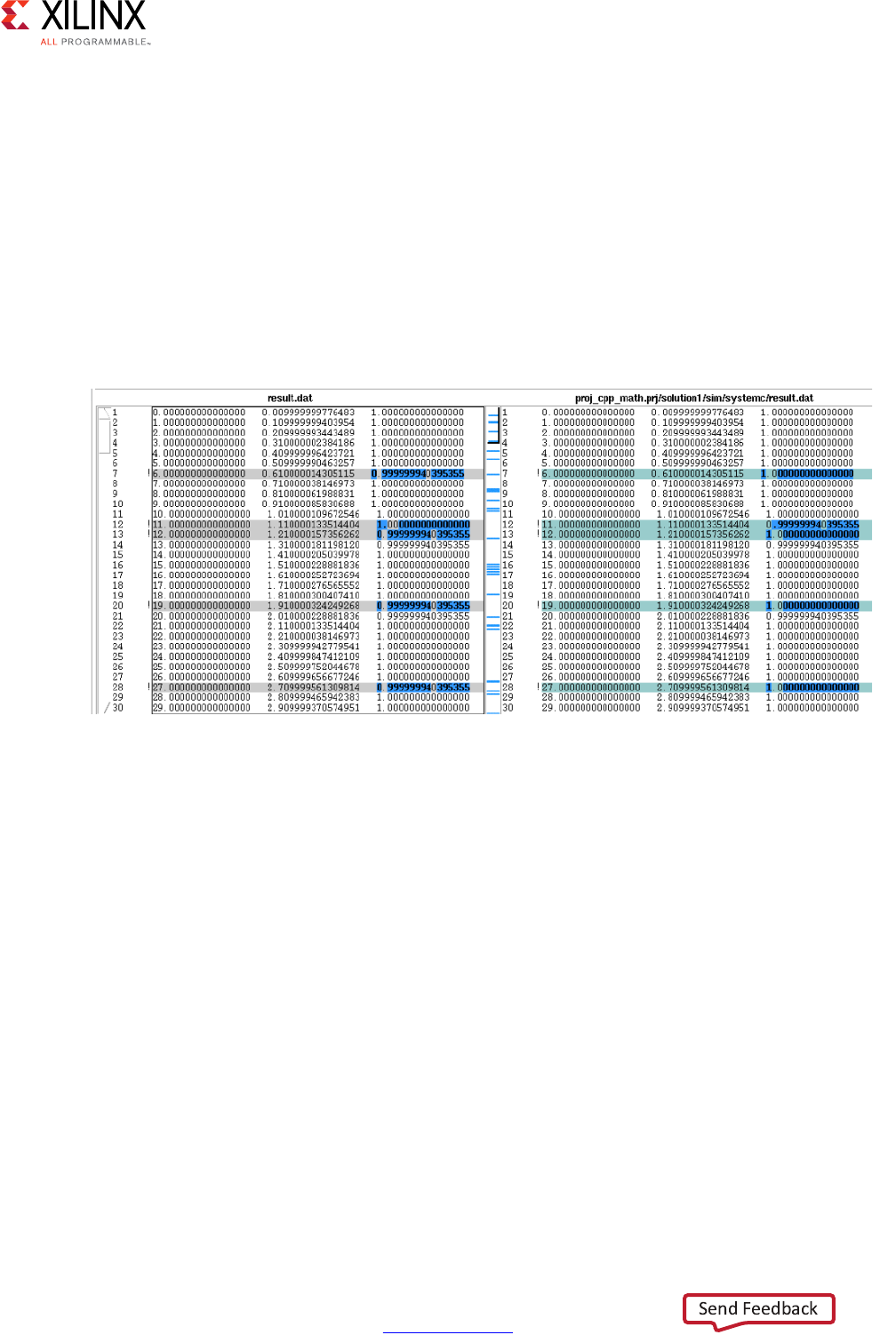
High-Level Synthesis 238
UG902 (v2017.1) April 5, 2017 www.xilinx.com
Chapter 2: High-Level Synthesis C Libraries
In this case, the results between C simulation and C/RTL co-simulation are different. Keep in
mind when comparing the outputs of simulation, any results written from the test bench are
written to the working directory where the simulation executes:
• C simulation: Folder <project>/<solution>/csim/build
• C/RTL co-simulation: Folder <project>/<solution>/sim/<RTL>
where <project> is the project folder, <solution> is the name of the solution folder and
<RTL> is the type of RTL verified (verilog or vhdl). The following figure shows a typical
comparison of the pre-synthesis results file on the left-hand side and the post-synthesis RTL
results file on the right-hand side. The output is shown in the third column.
The results of pre-synthesis simulation and post-synthesis simulation differ by fractional
amounts. You must decide whether these fractional amounts are acceptable in the final RTL
implementation.
The recommended flow for handling these differences is using a test bench that checks the
results to ensure that they lie within an acceptable error range. This can be accomplished by
creating two versions of the same function, one for synthesis and one as a reference
version. In this example, only function cpp_math is synthesized.
#include <cmath>
#include <fstream>
#include <iostream>
#include <iomanip>
#include <cstdlib>
using namespace std;
typedef float data_t;
data_t cpp_math(data_t angle) {
data_t s = sinf(angle);
data_t c = cosf(angle);
X-Ref Target - Figure 2-4
Figure 2-4: Pre-Synthesis and Post-Synthesis Simulation Differences

High-Level Synthesis 239
UG902 (v2017.1) April 5, 2017 www.xilinx.com
Chapter 2: High-Level Synthesis C Libraries
return sqrtf(s*s+c*c);
}
data_t cpp_math_sw(data_t angle) {
data_t s = sinf(angle);
data_t c = cosf(angle);
return sqrtf(s*s+c*c);
}
The test bench to verify the design compares the outputs of both functions to determine
the difference, using variable diff in the following example. During C simulation both
functions produce identical outputs. During C/RTL co-simulation function cpp_math
produces different results and the difference in results are checked.
int main() {
data_t angle = 0.01;
data_t output, exp_output, diff;
int retval=0;
for (data_t i = 0; i <= 250; i++) {
output = cpp_math(angle);
exp_output = cpp_math_sw(angle);
// Check for differences
diff = ( (exp_output > output) ? exp_output - output : output - exp_output);
if (diff > 0.0000005) {
printf("Difference %.10f exceeds tolerance at angle %.10f \n", diff, angle);
retval=1;
}
angle = angle + .1;
}
if (retval != 0) {
printf("Test failed !!!\n");
retval=1;
} else {
printf("Test passed !\n");
}
// Return 0 if the test passes
return retval;
}
If the margin of difference is lowered to 0.00000005, this test bench highlights the margin
of error during C/RTL co-simulation:
Difference 0.0000000596 at angle 1.1100001335
Difference 0.0000000596 at angle 1.2100001574
Difference 0.0000000596 at angle 1.5100002289
Difference 0.0000000596 at angle 1.6100002527
etc..
When using the standard C math libraries (math.h and cmath.h) create a “smart” test
bench to verify any differences in accuracy are acceptable.

High-Level Synthesis 240
UG902 (v2017.1) April 5, 2017 www.xilinx.com
Chapter 2: High-Level Synthesis C Libraries
Verification Option 2: HLS Math Library and Validate Differences
An alternative verification option is to convert the source code to use the HLS math library.
With this option, there are no differences between the C simulation and C/RTL
co-simulation results. The following example shows how the code above is modified to use
the hls_math.h library.
Note: This option is only available in C++.
•Include the hls_math.h header file.
• Replace the math functions with the equivalent hls:: function.
#include <cmath>
#include "hls_math.h"
#include <fstream>
#include <iostream>
#include <iomanip>
#include <cstdlib>
using namespace std;
typedef float data_t;
data_t cpp_math(data_t angle) {
data_t s = hls::sinf(angle);
data_t c = hls::cosf(angle);
return hls::sqrtf(s*s+c*c);
}
With this verification option there is now a difference between the C simulation results
using the HLS math library and those previously obtained using the standard C math
libraries. These difference should be validated with C simulation using a “smart” test bench
similar to option 1.
In cases where there are many math functions and updating the code is painful, a third
option can be used.
Verification Option 3: HLS Math Library File and Validate Differences
Including the HLS math library file lib_hlsm.cpp as a design file ensures Vivado HLS uses
the HLS math library for C simulation. This option is identical to option2 however it does
not require the C code to be modified.
The HLS math library file is located in the src directory in the Vivado HLS installation area.
Simply copy the file to your local folder and add the file as a standard design file.
Note: This option is only available in C++.
As with option 2, with this option there is now a difference between the C simulation results
using the HLS math library file and those previously obtained without adding this file.
These difference should be validated with C simulation using a “smart” test bench similar to
option 1.

High-Level Synthesis 241
UG902 (v2017.1) April 5, 2017 www.xilinx.com
Chapter 2: High-Level Synthesis C Libraries
Common Synthesis Errors
The following are common use errors when synthesizing math functions. These are often
(but not exclusively) caused by converting C functions to C++ to take advantage of
synthesis for math functions.
C++ cmath.h
If the C++ cmath.h header file is used, the floating point functions (for example, sinf
and cosf) can be used. These result in 32-bit operations in hardware. The cmath.h header
file also overloads the standard functions (for example, sin and cos) so they can be used
for float and double types.
C math.h
If the C math.h library is used, the single-precision functions (for example, sinf and
cosf) are required to synthesize 32-bit floating point operations. All standard function calls
(for example, sin and cos) result in doubles and 64-bit double-precision operations being
synthesized.
Cautions
When converting C functions to C++ to take advantage of math.h support, be sure that the
new C++ code compiles correctly before synthesizing with Vivado HLS. For example, if
sqrtf() is used in the code with math.h, it requires the following code extern added to
the C++ code to support it:
#include <math.h>
extern “C” float sqrtf(float);
To avoid unnecessary hardware caused by type conversion, follow the warnings on mixing
double and float types discussed in Floats and Doubles in Chapter 3.
HLS Video Library
The video library contains functions to help address several aspects of modeling video
design in C++. The following topics are addressed in this section:
• Video Functions
• Data Types
• Memory Line Buffer
•Memory Window
High-Level Synthesis 242
UG902 (v2017.1) April 5, 2017 www.xilinx.com
Chapter 2: High-Level Synthesis C Libraries
Using the Video Library
The Vivado HLS video library requires the hls_video.h header file. This file includes all
image and video processing specific video types and functions provided by Vivado HLS.
When using the Vivado HLS video library, the only additional usage requirement is as
follows.
The design is written in C++ and uses the hls namespace:
#include <hls_video.h>
hls::rgb_8 video_data[1920][1080]
You can use alternatively scoped naming as shown in the following example:
#include <hls_video.h>
using namespace hls;
rgb_8 video_data[1920][1080]
Video Data Types
The data types provided in the HLS Video Library are used to ensure the output RTL created
by synthesis can be seamlessly integrated with any Xilinx® Video IP blocks used in the
system.
When using any Xilinx Video IP in your system, refer to the IP data sheet and determine the
format used to send or receive the video data. Use the appropriate video data type in the C
code and the RTL created by synthesis may be connected to the Xilinx Video IP.
The library includes the following data types. All data types support 8-bit data only.
Table 2-5: Video Data Types
Data Type
Name Field 0 (8 bits) Field 1 (8 bits) Field 2 (8 bits) Field 3 (8 bits)
yuv422_8 Y UV Not Used Not Used
yuv444_8 Y U V Not Used
rgb_8 G B R Not Used
yuva422_8 Y UV A Not Used
yuva444_8 Y U V A
rgba_8 G B R A
yuva420_8 Y AUV Not Used Not Used
yuvd422_8 U UV D Not Used
yuvd444_8 Y U V D
rgbd_8 G B R D
High-Level Synthesis 243
UG902 (v2017.1) April 5, 2017 www.xilinx.com
Chapter 2: High-Level Synthesis C Libraries
After the hls_video.h library is included, the data types can be freely used in the source
code.
#include "hls_video.h"
hls::rgb_8 video_data[1920][1080]
Memory Line Buffer
The LineBuffer class is a C++ class that allows you to easily declare and manage line buffers
within your algorithmic code. This class provides all the methods required for instantiating
and working with line buffers. The LineBuffer class works with all data types.
The main features of the LineBuffer class are:
• Support for all data types through parameterization
• User-defined number of rows and columns
• Automatic banking of rows into separate memory banks for increased memory
bandwidth
• Provides all the methods for using and debugging line buffers in an algorithmic design
The LineBuffer class has the following methods, explained below:
•shift_pixels_up()
•shift_pixels_down()
• insert_bottom_row()
• insert_top_row()
• getval(row,column)
To illustrate the usage of the LineBuffer class, the following data set is assumed at the start
of all examples.
bayer_8 RGB Not Used Not Used Not Used
luma_8 Y Not Used Not Used Not Used
Table 2-5: Video Data Types (Cont’d)
Data Type
Name Field 0 (8 bits) Field 1 (8 bits) Field 2 (8 bits) Field 3 (8 bits)
Table 2-6: Data Set for LineBuffer Examples
Row Column 0 Column 1 Column 2 Column 3 Column 4
Row 012345
Row 1678910
Row 21112131415
High-Level Synthesis 244
UG902 (v2017.1) April 5, 2017 www.xilinx.com
Chapter 2: High-Level Synthesis C Libraries
A line buffer can be instantiated in an algorithm by using the LineBuffer data type,
shown in this example specifying a LineBuffer variable for the data in the table above:
// hls::LineBuffer<rows, columns, type> variable;
hls::LineBuffer<3,5, char> Buff_A;
The LineBuffer class assumes the data entering the block instantiating the line buffer is
arranged in raster scan order. Each new data item is therefore stored in a different column
than the previous data item.
Inserting new values, while preserving a finite number of previous values in a column,
requires a vertical shift between rows for a given column. After the shift is complete, a new
data value can be inserted at either the top or the bottom of the column.
For example, to insert the value 100 to the top of column 2 of the line buffer set:
Buff_A.shift_pixels_down(2);
Buff_A.insert_top_row(100,2);
This results in the new data set shown in the following table.
To insert the value 100 to the bottom of column 2 of the line buffer set in Table 2-6 use of
the following:
Buff_A.shift_pixels_up(2);
Buff_A.insert_bottom_row(100,2);
This results in the new data set shown in the following table.
The shift and insert methods both require the column value on which to operate.
All values stored by a LineBuffer instance are available using the getval(row,column)
method. Returns the value of any location inside the line buffer. For example, the following
results in variable Value being assigned the value 9:
Value = Buff_A.getval(1,3);
Table 2-7: Data Set After Shift Down and Insert Top Classes Used
Line Column 0 Column 1 Column 2 Column 3 Column 4
Row 0 1 2 100 4 5
Row 1673910
Row 2111281415
Table 2-8: Data Set After Shift Up and Insert Bottom Classes Used
Line Column 0 Column 1 Column 2 Column 3 Column 4
Row 012845
Row 16 713910
Row 2 11 12 100 14 15
High-Level Synthesis 245
UG902 (v2017.1) April 5, 2017 www.xilinx.com
Chapter 2: High-Level Synthesis C Libraries
Memory Window Buffer
The memory window C++ class allows you to declare and manage two-dimensional
memory windows. The main features of this class are:
• Support for all data types through parametrization
• User-defined number of rows and columns
• Automatic partitioning into individual registers for maximum bandwidth
• Provides all the methods to use and debug memory windows in the context of an
algorithm
The memory window class is supported by the following methods, explained below:
• shift_pixels_up()
• shift_pixels_down()
• shift_pixels_left()
• shift_pixels_right()
• insert_pixel(value,row,colum)
• insert_row()
• insert_bottom_row()
• insert_top_row()
• insert_col()
• insert_left_col()
• insert_right_col()
•getval(row, column)
You can instantiate a memory window in an algorithm by specifying a Window variable for
the following data type:
// hls::Window<row, column, type> variable;
hls::Window<3,3,char> Buff_B;
The memory window class examples in this section use the data set in the following table.
Table 2-9: Data Set for Memory Window Examples
Column 0 Column 1 Column 2 Row
123Row 0
678Row 1
11 12 13 Row 2
High-Level Synthesis 246
UG902 (v2017.1) April 5, 2017 www.xilinx.com
Chapter 2: High-Level Synthesis C Libraries
The Window class provides methods for moving data stored within the memory window up,
down, left, and right. Each shift operation clears space in the memory window for new data.
Buff_B.shift_pixels_up(); produces the following results.
Note: The New data has undefined, arbitrary values.
Buff_B.shift_pixels_down(); produces the following results.
Note: The New data has undefined, arbitrary values.
Buff_B.shift_pixels_left(); produces the following results.
Note: The New data has undefined, arbitrary values.
Buff_B.shift_pixels_right(); produces the following results.
Note: The New data has undefined, arbitrary values.
Table 2-10: Memory Window Data Set After Shift Up
Column 0 Column 1 Column 2 Row
678Row 0
11 12 13 Row 1
New New New Row 2
Table 2-11: Memory Window Data Set After Shift Down
Column 0 Column 1 Column 2 Row
New New New Row 0
123Row 1
678Row 2
Table 2-12: Memory Window Data Set After Shift Left
Column 0 Column 1 Column 2 Row
23NewRow 0
78NewRow 1
12 13 New Row 2
Table 2-13: Memory Window Data Set After Shift Right
Column 0 Column 1 Column 2 Row
New 1 2 Row 0
New 6 7 Row 1
New 11 12 Row 2
High-Level Synthesis 247
UG902 (v2017.1) April 5, 2017 www.xilinx.com
Chapter 2: High-Level Synthesis C Libraries
The Window class allows you to insert and retrieve data from any location within the
memory window. It also supports block insertion of data on the boundaries of the memory
window.
To insert data into any location of the memory window, use the following:
insert_pixel(value,row,column);
For example, you can place the value 100 into row 1, column 1 of the memory window
using:
Buff_B.insert_pixel(100,1,1);
This operation produces the following results.
Block level insertion requires that you provide an array of data elements to insert on a
boundary. The methods provided by the window class are:
•insert_row()
• insert_bottom_row()
• insert_top_row()
•insert_col()
•insert_left_col()
•insert_right_col()
The insert_row and insert_col methods take an array and a row or col location arguments
and place the contents in the specified row or column. The insert-row method:
char C[3] = {50, 50, 50};
Buff_B.insert_row(C,1);
results in the following:
Table 2-14: Memory Window Data Set After Insertion Operation at Location 1,1
Column 0 Column 1 Column 2 Row
123Row 0
6 100 8 Row 1
11 12 13 Row 2
Table 2-15: Memory Window Data Set After the Insertion at Row 1 Using an Array
Column 0 Column 1 Column 2 Row
123Row 0
50 50 50 Row 1
11 12 13 Row 2
High-Level Synthesis 248
UG902 (v2017.1) April 5, 2017 www.xilinx.com
Chapter 2: High-Level Synthesis C Libraries
The insert_bottom_row, insert_top_row, insert_left_col and insert_right_col methods, simply
take an array argument. For example, when C is an array of three elements in which each
element has the value of 50, you can insert the value 50 across the bottom boundary of the
memory window using the following operation:
char C[3] = {50, 50, 50};
Buff_B.insert_bottom_row(C);
This operation produces the following results.
The other edge insertion methods for the window class work in the same way as the
insert_bottom_row() method.
To retrieve data can from a memory window, use:
getval(row,column)
For example:
A = Buff_B.getval(0,1);
results in:
A = 50
Video Functions
The video processing functions included in the HLS Video library are compatible with
existing OpenCV functions and are similarly named. They do not directly replace existing
OpenCV video library functions. The video processing functions use a data type hls::Mat.
This data type allows the functions to be synthesized and implemented as high
performance hardware.
Three types of functions are provided in the HLS Video Library:
• OpenCV Interface Functions: Converts data to and from the AXI4 streaming data type
and the standard OpenCV data types. These functions allow any OpenCV functions
executed in software to transfer data, via the AXI4 streaming functions, to and from the
hardware block created by HLS.
• AXI Interface Functions: These functions are used to convert the video data to and from
the hls::Mat data type used in the Video functions.
Table 2-16: Memory Window Data Set After Insert Bottom Operation Using an Array
Column 0 Column 1 Column 2 Row
123Row 0
678Row 1
50 50 50 Row 2

High-Level Synthesis 249
UG902 (v2017.1) April 5, 2017 www.xilinx.com
Chapter 2: High-Level Synthesis C Libraries
• Video Processing Functions: Compatible with standard OpenCV functions for
manipulating and processing video images. These functions use the hls::mat data
type and are synthesized by Vivado HLS.
OpenCV Interface Functions
In a typical video system using OpenCV functions, most of the algorithm remains on the
CPU using OpenCV functions. Only those parts of the algorithm that require acceleration in
the FPGA fabric are synthesized and therefore updated to use the Vivado HLS video
functions.
Because the AXI4 streaming protocol is commonly used as the interface between the code
that remains on the CPU and the functions to be synthesized, the OpenCV interface
functions are provided to enable the data transfer between the OpenCV code running on
the CPU and the synthesized hardware function running on FPGA fabric.
Using the interface functions to transform the data before passing it to the function to be
synthesized ensures a high-performance system. In addition to transforming the data, the
functions also include the means of converting OpenCV data formats to and from the
Vivado HLS Video Library data types, for example hls::Mat.
To use the OpenCV interface functions, you must include the header file hls_opencv.h.
These functions are used in the code that remains on the CPU.
AXI4-Interface Functions
The AXI4-Interface functions are used to transfer data into and out of the function to be
synthesized. The video functions to be synthesized use the hls::Mat data type for an
image.
The AXI4-Interface I/O functions discussed below allow you to convert the hls::Mat data
type.
Video Processing Functions
The video processing functions included in the Vivado HLS Video Library are specifically for
manipulating video images. Most of these functions are designed for accelerating
corresponding OpenCV functions, which have a similar signature and usage.
Using Video Functions
The following example demonstrates how each of three types of video functions are used.
In the test bench shown below:
• The data starts as standard OpenCV image data.
• This is converted to AXI4-Stream format using one of the OpenCV Interface Functions.

High-Level Synthesis 250
UG902 (v2017.1) April 5, 2017 www.xilinx.com
Chapter 2: High-Level Synthesis C Libraries
• The AXI4-Stream format is used for the input and output to the function for synthesis.
• Finally, the data is converted back into standard OpenCV formatted data.
This process ensures the test bench operates using the standard OpenCV functions used in
many software applications. The test bench may be executed on a CPU with the following:
#include "hls_video.h"
int main (int argc, char** argv) {
// Load data in OpenCV image format
IplImage* src = cvLoadImage(INPUT_IMAGE);
IplImage* dst = cvCreateImage(cvGetSize(src), src->depth, src->nChannels);
AXI_STREAM src_axi, dst_axi;
// Convert OpenCV format to AXI4 Stream format
IplImage2AXIvideo(src, src_axi);
// Call the function to be synthesized
image_filter(src_axi, dst_axi, src->height, src->width);
// Convert the AXI4 Stream data to OpenCV format
AXIvideo2IplImage(dst_axi, dst);
// Standard OpenCV image functions
cvSaveImage(OUTPUT_IMAGE, dst);
opencv_image_filter(src, dst);
cvSaveImage(OUTPUT_IMAGE_GOLDEN, dst);
cvReleaseImage(&src);
cvReleaseImage(&dst);
char tempbuf[2000];
sprintf(tempbuf, "diff --brief -w %s %s", OUTPUT_IMAGE, OUTPUT_IMAGE_GOLDEN);
int ret = system(tempbuf);
if (ret != 0) {
printf("Test Failed!\n");
ret = 1;
} else {
printf("Test Passed!\n");
}
return ret;
}
The function to be synthesized, image_filter, is shown below. The characteristics of this
function are:
• The input data type is the AXI4-Interface formatted data.
• The AXI4-Interface formatted data is converted to hls::Mat format using an the
AXI4-Interface function.
• The Video Processing Functions, named in a similar manner to their equivalent OpenCV
functions, process the image and will synthesize into a high-quality FPGA
implementation.
High-Level Synthesis 251
UG902 (v2017.1) April 5, 2017 www.xilinx.com
Chapter 2: High-Level Synthesis C Libraries
• The data is converted back to AXI4-Stream format and output.
#include "hls_video.h"
typedef hls::stream<ap_axiu<32,1,1,1> > AXI_STREAM;
typedef hls::Scalar<3, unsigned char> RGB_PIXEL;
typedef hls::Mat<MAX_HEIGHT, MAX_WIDTH, HLS_8UC3> RGB_IMAGE;
void image_filter(AXI_STREAM& INPUT_STREAM, AXI_STREAM& OUTPUT_STREAM, int rows, int
cols) {
//Create AXI streaming interfaces for the core
RGB_IMAGE img_0(rows, cols);
RGB_IMAGE img_1(rows, cols);
RGB_IMAGE img_2(rows, cols);
RGB_IMAGE img_3(rows, cols);
RGB_IMAGE img_4(rows, cols);
RGB_IMAGE img_5(rows, cols);
RGB_PIXEL pix(50, 50, 50);
// Convert AXI4 Stream data to hls::mat format
hls::AXIvideo2Mat(INPUT_STREAM, img_0);
// Execute the video pipelines
hls::Sobel<1,0,3>(img_0, img_1);
hls::SubS(img_1, pix, img_2);
hls::Scale(img_2, img_3, 2, 0);
hls::Erode(img_3, img_4);
hls::Dilate(img_4, img_5);
// Convert the hls::mat format to AXI4 Stream format
hls::Mat2AXIvideo(img_5, OUTPUT_STREAM);
}
Using all three types of functions allows you to implement video functions on an FPGA and
maintain a seamless transfer of data between the video functions optimized for synthesis
and the OpenCV functions and data which remain in the test bench (executing on the CPU).
The following table summarizes the functions provided in the HLS Video Library.
Table 2-17: HLS Video Library
Function Type Function Description
OpenCV
Interface
AXIvideo2cvMat Converts data from AXI4 video stream (hls::stream)
format to OpenCV cv::Mat format
OpenCV
Interface
AXIvideo2CvMat Converts data from AXI4 video stream (hls::stream)
format to OpenCV CvMat format2
OpenCV
Interface
AXIvideo2IplImage Converts data from AXI4 video stream (hls::stream)
format to OpenCV IplImage format
OpenCV
Interface
cvMat2AXIvideo Converts data from OpenCV cv::Mat format to AXI4 video
stream (hls::stream) format
OpenCV
Interface
CvMat2AXIvideo Converts data from OpenCV CvMat format to AXI4 video
stream (hls::stream) format

High-Level Synthesis 252
UG902 (v2017.1) April 5, 2017 www.xilinx.com
Chapter 2: High-Level Synthesis C Libraries
OpenCV
Interface
cvMat2hlsMat Converts data from OpenCV cv::Mat format to hls::Mat
format
OpenCV
Interface
CvMat2hlsMat Converts data from OpenCV CvMat format to hls::Mat
format
OpenCV
Interface
CvMat2hlsWindow Converts data from OpenCV CvMat format to
hls::Window format
OpenCV
Interface
hlsMat2cvMat Converts data from hls::Mat format to OpenCV cv::Mat
format
OpenCV
Interface
hlsMat2CvMat Converts data from hls::Mat format to OpenCV CvMat
format
OpenCV
Interface
hlsMat2IplImage Converts data from hls::Mat format to OpenCV IplImage
format
OpenCV
Interface
hlsWindow2CvMat Converts data from hls::Window format to OpenCV
CvMat format
OpenCV
Interface
IplImage2AXIvideo Converts data from OpenCV IplImage format to AXI4
video stream (hls::stream) format
OpenCV
Interface
IplImage2hlsMat Converts data from OpenCV IplImage format to hls::Mat
format
AXI4-Interface AXIvideo2Mat Converts image data stored in hls::Mat format to an AXI4
video stream (hls::stream) format
AXI4-Interface Mat2AXIvideo Converts image data stored in AXI4 video stream
(hls::stream) format to an image of hls::Mat format
AX-Interface Array2Mat Converts image data stored in an array to an image of
hls::Mat format.
AX-Interface Array2Mat Converts image data stored hls::Mat format to an array.
Video
Processing
AbsDiff Computes the absolute difference between two input
images src1 and src2 and saves the result in dst
Video
Processing
AddS Computes the per-element sum of an image src and a
scalar scl
Video
Processing
AddWeighted Computes the weighted per-element sum of two image
src1 and src2
Video
Processing
And Calculates the per-element bitwise logical conjunction of
two images src1 and src2
Video
Processing
Avg Calculates an average of elements in image src
Video
Processing
AvgSdv Calculates an average of elements in image src
Video
Processing
Cmp Performs the per-element comparison of two input
images src1 and src2
Video
Processing
CmpS Performs the comparison between the elements of input
images src and the input value and saves the result in dst
Table 2-17: HLS Video Library (Cont’d)
Function Type Function Description

High-Level Synthesis 253
UG902 (v2017.1) April 5, 2017 www.xilinx.com
Chapter 2: High-Level Synthesis C Libraries
Video
Processing
CornerHarris This function implements a Harris edge/corner detector
Video
Processing
CvtColor Converts a color image from or to a grayscale image
Video
Processing
Dilate Dilates the image src using the specified structuring
element constructed within the kernel
Video
Processing
Duplicate Copies the input image src to two output images dst1
and dst2, for divergent point of two datapaths
Video
Processing
EqualizeHist Computes a histogram of each frame and uses it to
normalize the range of the following frame
Video
Processing
Erode Erodes the image src using the specified structuring
element constructed within kernel
Video
Processing
FASTX Implements the FAST corner detector, generating either a
mask of corners, or an array of coordinates
Video
Processing
Filter2D Applies an arbitrary linear filter to the image src using the
specified kernel
Video
Processing
GaussianBlur Applies a normalized 2D Gaussian Blur filter to the input
Video
Processing
Harris This function implements a Harris edge or corner
detector
Video
Processing
HoughLines2 Implements the Hough line transform
Video
Processing
Integral Implements the computation of an integral image
Video
Processing
InitUndistortRectifyMap Generates map1 and map2, based on a set of parameters,
where map1 and map2 are suitable inputs for
hls::Remap()
Video
Processing
Max Calculates per-element maximum of two input images
src1 and src2 and saves the result in dst
Video
Processing
MaxS Calculates the maximum between the elements of input
images src and the input value and saves the result in dst
Video
Processing
Mean Calculates an average of elements in image src, and
return the value of first channel of result scalar
Video
Processing
Merge Composes a multichannel image dst from several
single-channel images
Video
Processing
Min Calculates per-element minimum of two input images
src1 and src2 and saves the result in dst
Video
Processing
MinMaxLoc Finds the global minimum and maximum and their
locations in input image src
Video
Processing
MinS Calculates the minimum between the elements of input
images src and the input value and saves the result in dst
Table 2-17: HLS Video Library (Cont’d)
Function Type Function Description

High-Level Synthesis 254
UG902 (v2017.1) April 5, 2017 www.xilinx.com
Chapter 2: High-Level Synthesis C Libraries
As shown in the example above, the video functions are not direct replacements for
OpenCV functions. They use input and output arrays to process the data and typically use
template parameters.
Video
Processing
Mul Calculates the per-element product of two input images
src1 and src2
Video
Processing
Not Performs per-element bitwise inversion of image src
Video
Processing
PaintMask Each pixel of the destination image is either set to color
(if mask is not zero) or the corresponding pixel from the
input image
Video
Processing
PyrDown Blurs the image and then reduces the size by a factor of 2.
Video
Processing
PyrUp Upsamples the image by a factor of 2 and then blurs the
image.
Video
Processing
Range Sets all value in image src by the following rule and return
the result as image dst
Video
Processing
Remap Remaps the source image src to the destination image dst
according to the given remapping
Video
Processing
Reduce Reduces 2D image src along dimension dim to a vector
dst
Video
Processing
Resize Resizes the input image to the size of the output image
using bilinear interpolation
Video
Processing
Set Sets elements in image src to a given scalar value scl
Video
Processing
Scale Converts an input image src with optional linear
transformation
Video
Processing
Sobel Computes a horizontal or vertical Sobel filter, returning
an estimate of the horizontal or vertical derivative, using
a filter
Video
Processing
Split Divides a multichannel image src from several
single-channel images
Video
Processing
SubRS Computes the differences between scalar value scl and
elements of image src
Video
Processing
SubS Computes the differences between elements of image src
and scalar value scl
Video
Processing
Sum Sums the elements of an image
Video
Processing
Threshold Performs a fixed-level threshold to each element in a
single-channel image
Video
Processing
Zero Sets elements in image src to 0
Table 2-17: HLS Video Library (Cont’d)
Function Type Function Description

High-Level Synthesis 255
UG902 (v2017.1) April 5, 2017 www.xilinx.com
Chapter 2: High-Level Synthesis C Libraries
A complete description of all functions in the HLS video library is provided in Chapter 4,
High-Level Synthesis Reference Guide.
Optimizing Video Functions for Performance
The HLS video functions are pre-optimized to ensure a high-quality and high-performance
implementation. The functions already include the optimization directives required to
process data at a rate of one sample per clock.
The exact performance metrics of the video functions depends upon the clock rate and the
target device specifications. Refer to the synthesis report for complete details on the final
performance achieved after synthesis.
The previous example is repeated below to highlight the only optimizations required to
achieve a complete high-performance design.
• Because the functions are already pipelined, adding the DATAFLOW optimization
ensures the pipelined functions will execute in parallel.
• In this example, the data type is an hls::stream which is automatically implemented
as a FIFO of depth 1: there is no requirement to use the config_dataflow
configuration to control the size of the dataflow memory channels.
• Implementing the input and output ports with an AXI4-Stream interface (axis) ensures a
high-performance streaming interface.
• Optionally, implementing the block-level protocol with an AXI4-Lite slave interface
would allow the synthesized block to be controlled from a CPU.
#include "hls_video.h"
typedef hls::stream<ap_axiu<32,1,1,1> > AXI_STREAM;
typedef hls::Scalar<3, unsigned char> RGB_PIXEL;
typedef hls::Mat<MAX_HEIGHT, MAX_WIDTH, HLS_8UC3> RGB_IMAGE;
void image_filter(AXI_STREAM& INPUT_STREAM, AXI_STREAM& OUTPUT_STREAM, int rows, int
cols) {
#pragma HLS INTERFACE axis port=INPUT_STREAM
#pragma HLS INTERFACE axis port=OUTPUT_STREAM
#pragma HLS dataflow
//Create AXI streaming interfaces for the core
RGB_IMAGE img_0(rows, cols);
RGB_IMAGE img_1(rows, cols);
RGB_IMAGE img_2(rows, cols);
RGB_IMAGE img_3(rows, cols);
RGB_IMAGE img_4(rows, cols);
RGB_IMAGE img_5(rows, cols);
RGB_PIXEL pix(50, 50, 50);
// Convert AXI4 Stream data to hls::mat format
hls::AXIvideo2Mat(INPUT_STREAM, img_0);
// Execute the video pipelines
High-Level Synthesis 256
UG902 (v2017.1) April 5, 2017 www.xilinx.com
Chapter 2: High-Level Synthesis C Libraries
hls::Sobel<1,0,3>(img_0, img_1);
hls::SubS(img_1, pix, img_2);
hls::Scale(img_2, img_3, 2, 0);
hls::Erode(img_3, img_4);
hls::Dilate(img_4, img_5);
// Convert the hls::mat format to AXI4 Stream format
hls::Mat2AXIvideo(img_5, OUTPUT_STREAM);
}
HLS IP Libraries
Vivado HLS provides C libraries to implement a number of Xilinx IP blocks. The C libraries
allow the following Xilinx IP blocks to be directly inferred from the C source code ensuring
a high-quality implementation in the FPGA.
FFT IP Library
The Xilinx FFT IP block can be called within a C++ design using the library hls_fft.h. This
section explains how the FFT can be configured in your C++ code.
RECOMMENDED: Xilinx highly recommends that you review the LogiCORE IP Fast Fourier Transform
Product Guide (PG109) [Ref 5] for information on how to implement and use the features of the IP.
To use the FFT in your C++ code:
1. Include the hls_fft.h library in the code
2. Set the default parameters using the pre-defined struct hls::ip_fft::params_t
3. Define the run time configuration
4. Call the FFT function
5. Optionally, check the run time status
Table 2-18: HLS IP Libraries
Library Header File Description
hls_fft.h Allows the Xilinx LogiCORE IP FFT to be simulated in C and implemented using
the Xilinx LogiCORE block.
hls_fir.h Allows the Xilinx LogiCORE IP FIR to be simulated in C and implemented using
the Xilinx LogiCORE block.
hls_dds.h Allows the Xilinx LogiCORE IP DDS to be simulated in C and implemented
using the Xilinx LogiCORE block.
ap_shift_reg.h Provides a C++ class to implement a shift register which is implemented
directly using a Xilinx SRL primitive.

High-Level Synthesis 257
UG902 (v2017.1) April 5, 2017 www.xilinx.com
Chapter 2: High-Level Synthesis C Libraries
The following code examples provide a summary of how each of these steps is performed.
Each step is discussed in more detail below.
First, include the FFT library in the source code. This header file resides in the include
directory in the Vivado HLS installation area which is automatically searched when Vivado
HLS executes.
#include "hls_fft.h"
Define the static parameters of the FFT. This includes such things as input width, number of
channels, type of architecture. which do not change dynamically. The FFT library includes a
parameterization struct hls::ip_fft::params_t, which can be used to initialize all
static parameters with default values.
In this example, the default values for output ordering and the widths of the configuration
and status ports are over-ridden using a user-defined struct param1 based on the
pre-defined struct.
struct param1 : hls::ip_fft::params_t {
static const unsigned ordering_opt = hls::ip_fft::natural_order;
static const unsigned config_width = FFT_CONFIG_WIDTH;
static const unsigned status_width = FFT_STATUS_WIDTH;
};
Define types and variables for both the run time configuration and run time status. These
values can be dynamic and are therefore defined as variables in the C code which can
change and are accessed through APIs.
typedef hls::ip_fft::config_t<param1> config_t;
typedef hls::ip_fft::status_t<param1> status_t;
config_t fft_config1;
status_t fft_status1;
Next, set the run time configuration. This example sets the direction of the FFT (Forward or
Inverse) based on the value of variable “direction” and also set the value of the scaling
schedule.
fft_config1.setDir(direction);
fft_config1.setSch(0x2AB);
Call the FFT function using the HLS namespace with the defined static configuration
(param1 in this example). The function parameters are, in order, input data, output data,
output status and input configuration.
hls::fft<param1> (xn1, xk1, &fft_status1, &fft_config1);
Finally, check the output status. This example checks the overflow flag and stores the results
in variable “ovflo”.
*ovflo = fft_status1->getOvflo();

High-Level Synthesis 258
UG902 (v2017.1) April 5, 2017 www.xilinx.com
Chapter 2: High-Level Synthesis C Libraries
Design examples using the FFT C library are provided in the Vivado HLS examples and can
be accessed using menu option Help > Welcome > Open Example Project > Design
Examples > FFT.
FFT Static Parameters
The static parameters of the FFT define how the FFT is configured and specifies the fixed
parameters such as the size of the FFT, whether the size can be changed dynamically,
whether the implementation is pipelined or radix_4_burst_io.
The hls_fft.h header file defines a struct hls::ip_fft::params_t which can be used
to set default values for the static parameters. If the default values are to be used, the
parameterization struct can be used directly with the FFT function.
hls::fft<hls::ip_fft::params_t >
(xn1, xk1, &fft_status1, &fft_config1);
A more typical use is to change some of the parameters to non-default values. This is
performed by creating a new user-define parameterization struct based on the default
parameterization struct and changing some of the default values.
In this example, a new user struct my_fft_config is defined and with a new value for the
output ordering (changed to natural_order). All other static parameters to the FFT use the
default values (shown below in Table 2-20).
struct my_fft_config : hls::ip_fft::params_t {
static const unsigned ordering_opt = hls::ip_fft::natural_order;
};
hls::fft<my_fft_config >
(xn1, xk1, &fft_status1, &fft_config1);
The values used for the parameterization struct hls::ip_fft::params_t are explained
in the following table. The default values for the parameters and a list of possible values is
provided in Table 2-20.
RECOMMENDED: Xilinx highly recommends that you review the LogiCORE IP Fast Fourier Transform
Product Guide (PG109) [Ref 5] for details on the parameters and the implication for their settings.

High-Level Synthesis 259
UG902 (v2017.1) April 5, 2017 www.xilinx.com
Chapter 2: High-Level Synthesis C Libraries
When specifying parameter values which are not integer or boolean, the HLS FFT
namespace should be used.
For example the possible values for parameter butterfly_type in the following table are
use_luts and use_xtremedsp_slices. The values used in the C program should be
butterfly_type = hls::ip_fft::use_luts and butterfly_type =
hls::ip_fft::use_xtremedsp_slices.
The following table covers all features and functionality of the FFT IP. Features and
functionality not described in this table are not supported in the Vivado HLS
implementation.
Table 2-19: FFT Struct Parameters
Parameter Description
input_width Data input port width.
output_width Data output port width.
status_width Output status port width.
config_width Input configuration port width.
max_nfft The size of the FFT data set is specified as 1 << max_nfft.
has_nfft Determines if the size of the FFT can be run time configurable.
channels Number of channels.
arch_opt The implementation architecture.
phase_factor_width Configure the internal phase factor precision.
ordering_opt The output ordering mode.
ovflo Enable overflow mode.
scaling_opt Define the scaling options.
rounding_opt Define the rounding modes.
mem_data Specify using block or distributed RAM for data memory.
mem_phase_factors Specify using block or distributed RAM for phase factors memory.
mem_reorder Specify using block or distributed RAM for output reorder memory.
stages_block_ram Defines the number of block RAM stages used in the implementation.
mem_hybrid When block RAMs are specified for data, phase factor, or reorder buffer,
mem_hybrid specifies where or not to use a hybrid of block and distributed RAMs
to reduce block RAM count in certain configurations.
complex_mult_type Defines the types of multiplier to use for complex multiplications.
butterfly_type Defines the implementation used for the FFT butterfly.

High-Level Synthesis 260
UG902 (v2017.1) April 5, 2017 www.xilinx.com
Chapter 2: High-Level Synthesis C Libraries
Table 2-20: FFT Struct Parameters Values
Parameter C Type Default Value Valid Values
input_width unsigned 16 8-34
output_width unsigned 16 input_width to (input_width + max_nfft
+ 1)
status_width unsigned 8 Depends on FFT configuration
config_width unsigned 16 Depends on FFT configuration
max_nfft unsigned 10 3-16
has_nfft bool false True, False
channels unsigned 1 1-12
arch_opt unsigned pipelined_streaming_io automatically_select
pipelined_streaming_io
radix_4_burst_io
radix_2_burst_io
radix_2_lite_burst_io
phase_factor_width unsigned 16 8-34
ordering_opt unsigned bit_reversed_order bit_reversed_order
natural_order
ovflo bool true false
true
scaling_opt unsigned scaled scaled
unscaled
block_floating_point
rounding_opt unsigned truncation truncation
convergent_rounding
mem_data unsigned block_ram block_ram
distributed_ram
mem_phase_factors unsigned block_ram block_ram
distributed_ram
mem_reorder unsigned block_ram block_ram
distributed_ram
stages_block_ram unsigned (max_nfft < 10) ? 0 :
(max_nfft - 9)
0-11
mem_hybrid bool false false
true

High-Level Synthesis 261
UG902 (v2017.1) April 5, 2017 www.xilinx.com
Chapter 2: High-Level Synthesis C Libraries
FFT Run Time Configuration and Status
The FFT supports run time configuration and run time status monitoring through the
configuration and status ports. These ports are defined as arguments to the FFT function,
shown here as variables fft_status1 and fft_config1:
hls::fft<param1> (xn1, xk1, &fft_status1, &fft_config1);
The run time configuration and status can be accessed using the predefined structs from
the FFT C library:
• hls::ip_fft::config_t<param1>
• hls::ip_fft::status_t<param1>
Note: In both cases, the struct requires the name of the static parameterization struct, shown in
these examples as param1. Refer to the previous section for details on defining the static
parameterization struct.
The run time configuration struct allows the following actions to be performed in the C
code:
• Set the FFT length, if run time configuration is enabled
• Set the FFT direction as forward or inverse
• Set the scaling schedule
The FFT length can be set as follows:
typedef hls::ip_fft::config_t<param1> config_t;
config_t fft_config1;
// Set FFT length to 512 => log2(512) =>9
fft_config1-> setNfft(9);
IMPORTANT: The length specified during run time cannot exceed the size defined by max_nfft in the
static configuration.
complex_mult_type unsigned use_mults_resources use_luts
use_mults_resources
use_mults_performance
butterfly_type unsigned use_luts use_luts
use_xtremedsp_slices
Table 2-20: FFT Struct Parameters Values (Cont’d)

High-Level Synthesis 262
UG902 (v2017.1) April 5, 2017 www.xilinx.com
Chapter 2: High-Level Synthesis C Libraries
The FFT direction can be set as follows:
typedef hls::ip_fft::config_t<param1> config_t;
config_t fft_config1;
// Forward FFT
fft_config1->setDir(1);
// Inverse FFT
fft_config1->setDir(0);
The FFT scaling schedule can be set as follows:
typedef hls::ip_fft::config_t<param1> config_t;
config_t fft_config1;
fft_config1->setSch(0x2AB);
The output status port can be accessed using the pre-defined struct to determine:
• If any overflow occurred during the FFT
• The value of the block exponent
The FFT overflow mode can be checked as follows:
typedef hls::ip_fft::status_t<param1> status_t;
status_t fft_status1;
// Check the overflow flag
bool *ovflo = fft_status1->getOvflo();
IMPORTANT: After each transaction completes, check the overflow status to confirm the correct
operation of the FFT.
And the block exponent value can be obtained using:
typedef hls::ip_fft::status_t<param1> status_t;
status_t fft_status1;
// Obtain the block exponent
unsigned int *blk_exp = fft_status1-> getBlkExp();
Using the FFT Function
The FFT function is defined in the HLS namespace and can be called as follows:
hls::fft<STATIC_PARAM> (
INPUT_DATA_ARRAY,
OUTPUT_DATA_ARRAY,
OUTPUT_STATUS,
INPUT_RUN_TIME_CONFIGURATION);
The STATIC_PARAM is the static parameterization struct discussed in the earlier section FFT
Static Parameters. This defines the static parameters for the FFT.

High-Level Synthesis 263
UG902 (v2017.1) April 5, 2017 www.xilinx.com
Chapter 2: High-Level Synthesis C Libraries
Both the input and output data are supplied to the function as arrays (INPUT_DATA_ARRAY
and OUTPUT_DATA_ARRAY). In the final implementation, the ports on the FFT RTL block will
be implemented as AXI4-Stream ports. Xilinx recommends always using the FFT function in
a region using dataflow optimization (set_directive_dataflow), because this ensures
the arrays are implemented as streaming arrays. An alternative is to specify both arrays as
streaming using the set_directive_stream command.
IMPORTANT: The FFT cannot be used in a region which is pipelined. If high-performance operation is
required, pipeline the loops or functions before and after the FFT then use dataflow optimization on all
loops and functions in the region.
The data types for the arrays can be float or ap_fixed.
typedef float data_t;
complex<data_t> xn[FFT_LENGTH];
complex<data_t> xk[FFT_LENGTH];
To use fixed-point data types, the Vivado HLS arbitrary precision type ap_fixed should be
used.
#include "ap_fixed.h"
typedef ap_fixed<FFT_INPUT_WIDTH,1> data_in_t;
typedef ap_fixed<FFT_OUTPUT_WIDTH,FFT_OUTPUT_WIDTH-FFT_INPUT_WIDTH+1> data_out_t;
#include <complex>
typedef std::complex<data_in_t> cmpxData;
typedef std::complex<data_out_t> cmpxDataOut;
In both cases, the FFT should be parameterized with the same correct data sizes. In the case
of floating point data, the data widths will always be 32-bit and any other specified size will
be considered invalid.
TIP: The input and output width of the FFT can be configured to any arbitrary value within the
supported range. The variables which connect to the input and output parameters must be defined in
increments of 8-bit. For example, if the output width is configured as 33-bit, the output variable must
be defined as a 40-bit variable.
The multichannel functionality of the FFT can be used by using two-dimensional arrays for
the input and output data. In this case, the array data should be configured with the first
dimension representing each channel and the second dimension representing the FFT data.
typedef float data_t;
static complex<data_t> xn[CHANNEL][FFT_LENGTH];
static complex<data_t> xk[CHANELL][FFT_LENGTH];
High-Level Synthesis 264
UG902 (v2017.1) April 5, 2017 www.xilinx.com
Chapter 2: High-Level Synthesis C Libraries
The FFT core consumes and produces data as interleaved channels (for example, ch0-data0,
ch1-data0, ch2-data0, etc, ch0-data1, ch1-data1, ch2-data2, etc.). Therefore, to stream the
input or output arrays of the FFT using the same sequential order that the data was read or
written, you must fill or empty the two-dimensional arrays for multiple channels by
iterating through the channel index first, as shown in the following example:
cmpxData in_fft[FFT_CHANNELS][FFT_LENGTH];
cmpxData out_fft[FFT_CHANNELS][FFT_LENGTH];
// Write to FFT Input Array
for (unsigned i = 0; i < FFT_LENGTH; i++) {
for (unsigned j = 0; j < FFT_CHANNELS; ++j) {
in_fft[j][i] = in.read().data;
}
}
// Read from FFT Output Array
for (unsigned i = 0; i < FFT_LENGTH; i++) {
for (unsigned j = 0; j < FFT_CHANNELS; ++j) {
out.data = out_fft[j][i];
}
}
The OUTPUT_STATUS and INPUT_RUN_TIME_CONFIGURATION are the structs discussed in
the earlier section FFT Run Time Configuration.
Design examples using the FFT C library are provided in the Vivado HLS examples and can
be accessed using menu option Help > Welcome > Open Example Project > Design
Examples > FFT.
FIR Filter IP Library
The Xilinx FIR IP block can be called within a C++ design using the library hls_fir.h. This
section explains how the FIR can be configured in your C++ code.
RECOMMENDED: Xilinx highly recommends that you review the LogiCORE IP FIR Compiler Product
Guide (PG149) [Ref 6] for information on how to implement and use the features of the IP.
To use the FIR in your C++ code:
1. Include the hls_fir.h library in the code.
2. Set the static parameters using the pre-defined struct hls::ip_fir::params_t.
3. Call the FIR function.
4. Optionally, define a run time input configuration to modify some parameters
dynamically.
The following code examples provide a summary of how each of these steps is performed.
Each step is discussed in more detail below.

High-Level Synthesis 265
UG902 (v2017.1) April 5, 2017 www.xilinx.com
Chapter 2: High-Level Synthesis C Libraries
First, include the FIR library in the source code. This header file resides in the include
directory in the Vivado HLS installation area. This directory is automatically searched when
Vivado HLS executes. There is no need to specify the path to this directory if compiling
inside Vivado HLS.
#include "hls_fir.h"
Define the static parameters of the FIR. This includes such static attributes such as the input
width, the coefficients, the filter rate (single, decimation, hilbert). The FIR library includes a
parameterization struct hls::ip_fir::params_t which can be used to initialize all
static parameters with default values.
In this example, the coefficients are defined as residing in array coeff_vec and the default
values for the number of coefficients, the input width and the quantization mode are
over-ridden using a user a user-defined struct myconfig based on the pre-defined struct.
struct myconfig : hls::ip_fir::params_t {
static const double coeff_vec[sg_fir_srrc_coeffs_len];
static const unsigned num_coeffs = sg_fir_srrc_coeffs_len;
static const unsigned input_width = INPUT_WIDTH;
static const unsigned quantization = hls::ip_fir::quantize_only;
};
Create an instance of the FIR function using the HLS namespace with the defined static
parameters (myconfig in this example) and then call the function with the run method to
execute the function. The function arguments are, in order, input data and output data.
static hls::FIR<param1> fir1;
fir1.run(fir_in, fir_out);
Optionally, a run time input configuration can be used. In some modes of the FIR, the data
on this input determines how the coefficients are used during interleaved channels or when
coefficient reloading is required. This configuration can be dynamic and is therefore
defined as a variable. For a complete description of which modes require this input
configuration, refer to the LogiCORE IP FIR Compiler Product Guide (PG149) [Ref 6].
When the run time input configuration is used, the FIR function is called with three
arguments: input data, output data and input configuration.
// Define the configuration type
typedef ap_uint<8> config_t;
// Define the configuration variable
config_t fir_config = 8;
// Use the configuration in the FFT
static hls::FIR<param1> fir1;
fir1.run(fir_in, fir_out, &fir_config);
Design examples using the FIR C library are provided in the Vivado HLS examples and can
be accessed using menu option Help > Welcome > Open Example Project > Design
Examples > FIR.

High-Level Synthesis 266
UG902 (v2017.1) April 5, 2017 www.xilinx.com
Chapter 2: High-Level Synthesis C Libraries
FIR Static Parameters
The static parameters of the FIR define how the FIR IP is parameterized and specifies
non-dynamic items such as the input and output widths, the number of fractional bits, the
coefficient values, the interpolation and decimation rates. Most of these configurations
have default values: there are no default values for the coefficients.
The hls_fir.h header file defines a struct hls::ip_fir::params_t that can be
used to set the default values for most of the static parameters.
IMPORTANT: There are no defaults defined for the coefficients. Therefore, Xilinx does not recommend
using the pre-defined struct to directly initialize the FIR. A new user defined struct which specifies the
coefficients should always be used to perform the static parameterization.
In this example, a new user struct my_config is defined and with a new value for the
coefficients. The coefficients are specified as residing in array coeff_vec. All other
parameters to the FIR will use the default values (shown below in Table 2-22).
struct myconfig : hls::ip_fir::params_t {
static const double coeff_vec[sg_fir_srrc_coeffs_len];
};
static hls::FIR<myconfig> fir1;
fir1.run(fir_in, fir_out);
The following table describes the parameters used for the parametrization struct
hls::ip_fir::params_t. Table 2-22 provides the default values for the parameters and
a list of possible values.
RECOMMENDED: Xilinx highly recommends that you refer to the LogiCORE IP FIR Compiler Product
Guide (PG149) [Ref 6] for details on the parameters and the implication for their settings.
High-Level Synthesis 267
UG902 (v2017.1) April 5, 2017 www.xilinx.com
Chapter 2: High-Level Synthesis C Libraries
Table 2-21: FIR Struct Parameters
Parameter Description
input_width Data input port width
input_fractional_bits Number of fractional bits on the input port
output_width Data output port width
output_fractional_bits Number of fractional bits on the output port
coeff_width Bit-width of the coefficients
coeff_fractional_bits Number of fractional bits in the coefficients
num_coeffs Number of coefficients
coeff_sets Number of coefficient sets
input_length Number of samples in the input data
output_length Number of samples in the output data
num_channels Specify the number of channels of data to process
total_number_coeff Total number of coefficients
coeff_vec[total_num_coeff] The coefficient array
filter_type The type implementation used for the filter
rate_change Specifies integer or fractional rate changes
interp_rate The interpolation rate
decim_rate The decimation rate
zero_pack_factor Number of zero coefficients used in interpolation
rate_specification Specify the rate as frequency or period
hardware_oversampling_rate Specify the rate of over-sampling
sample_period The hardware oversample period
sample_frequency The hardware oversample frequency
quantization The quantization method to be used
best_precision Enable or disable the best precision
coeff_structure The type of coefficient structure to be used
output_rounding_mode Type of rounding used on the output
filter_arch Selects a systolic or transposed architecture
optimization_goal Specify a speed or area goal for optimization
inter_column_pipe_length The pipeline length required between DSP columns
column_config Specifies the number of DSP48 column
config_method Specifies how the DSP48 columns are configured
coeff_padding Number of zero padding added to the front of the filter

High-Level Synthesis 268
UG902 (v2017.1) April 5, 2017 www.xilinx.com
Chapter 2: High-Level Synthesis C Libraries
When specifying parameter values that are not integer or boolean, the HLS FIR namespace
should be used.
For example the possible values for rate_change are shown in the following table to be
integer and fixed_fractional. The values used in the C program should be
rate_change = hls::ip_fir::integer and rate_change =
hls::ip_fir::fixed_fractional.
The following table covers all features and functionality of the FIR IP. Features and
functionality not described in this table are not supported in the Vivado HLS
implementation.
Table 2-22: FIR Struct Parameters Values
Parameter C Type Default Value Valid Values
input_width unsigned 16 No limitation
input_fractional_bits unsigned 0 Limited by size of input_width
output_width unsigned 24 No limitation
output_fractional_bits unsigned 0 Limited by size of output_width
coeff_width unsigned 16 No limitation
coeff_fractional_bits unsigned 0 Limited by size of coeff_width
num_coeffs bool 21 Full
coeff_sets unsigned 1 1-1024
input_length unsigned 21 No limitation
output_length unsigned 21 No limitation
num_channels unsigned 1 1-1024
total_number_coeff unsigned 21 num_coeffs * coeff_sets
coeff_vec[total_num_coeff] double
array
None Not applicable
filter_type unsigned single_rate single_rate, interpolation,
decimation, hilbert_filter,
interpolated
rate_change unsigned integer integer, fixed_fractional
interp_rate unsigned 1 1-1024
decim_rate unsigned 1 1-1024
zero_pack_factor unsigned 1 1-8
rate_specification unsigned period frequency, period
hardware_oversampling_rate unsigned 1 No Limitation
sample_period bool 1 No Limitation
sample_frequency unsigned 0.001 No Limitation

High-Level Synthesis 269
UG902 (v2017.1) April 5, 2017 www.xilinx.com
Chapter 2: High-Level Synthesis C Libraries
Using the FIR Function
The FIR function is defined in the HLS namespace and can be called as follows:
// Create an instance of the FIR
static hls::FIR<STATIC_PARAM> fir1;
// Execute the FIR instance fir1
fir1.run(INPUT_DATA_ARRAY, OUTPUT_DATA_ARRAY);
The STATIC_PARAM is the static parameterization struct discussed in the earlier section
FIR Static Parameters. This defines most static parameters for the FIR.
Both the input and output data are supplied to the function as arrays (INPUT_DATA_ARRAY
and OUTPUT_DATA_ARRAY). In the final implementation, these ports on the FIR IP will be
implemented as AXI4-Stream ports. Xilinx recommends always using the FIR function in a
region using the dataflow optimization (set_directive_dataflow), because this
ensures the arrays are implemented as streaming arrays. An alternative is to specify both
arrays as streaming using the set_directive_stream command.
quantization unsigned integer_coefficients integer_coefficients,
quantize_only,
maximize_dynamic_range
best_precision unsigned false false
true
coeff_structure unsigned non_symmetric inferred, non_symmetric,
symmetric, negative_symmetric,
half_band, hilbert
output_rounding_mode unsigned full_precision full_precision, truncate_lsbs,
non_symmetric_rounding_down,
non_symmetric_rounding_up,
s y m m e t r i c _ r o u n d i n g _ t o _ z e r o ,
symmetric_rounding_to_infinity,
convergent_rounding_to_even,
convergent_rounding_to_odd
filter_arch unsigned systolic_multiply_accumulate systolic_multiply_accumulate,
transpose_multiply_accumulate
optimization_goal unsigned area area, speed
inter_column_pipe_length unsigned 4 1-16
column_config unsigned 1 Limited by number of DSP48s
used
config_method unsigned single single, by_channel
coeff_padding bool false false
true
Table 2-22: FIR Struct Parameters Values (Cont’d)

High-Level Synthesis 270
UG902 (v2017.1) April 5, 2017 www.xilinx.com
Chapter 2: High-Level Synthesis C Libraries
IMPORTANT: The FIR cannot be used in a region which is pipelined. If high-performance operation is
required, pipeline the loops or functions before and after the FIR then use dataflow optimization on all
loops and functions in the region.
The multichannel functionality of the FIR is supported through interleaving the data in a
single input and single output array.
• The size of the input array should be large enough to accommodate all samples:
num_channels * input_length.
• The output array size should be specified to contain all output samples: num_channels
* output_length.
The following code example demonstrates, for two channels, how the data is interleaved. In
this example, the top-level function has two channels of input data (din_i, din_q) and
two channels of output data (dout_i, dout_q). Two functions, at the front-end (fe) and
back-end (be) are used to correctly order the data in the FIR input array and extract it from
the FIR output array.
void dummy_fe(din_t din_i[LENGTH], din_t din_q[LENGTH], din_t out[FIR_LENGTH]) {
for (unsigned i = 0; i < LENGTH; ++i) {
out[2*i] = din_i[i];
out[2*i + 1] = din_q[i];
}
}
void dummy_be(dout_t in[FIR_LENGTH], dout_t dout_i[LENGTH], dout_t dout_q[LENGTH]) {
for(unsigned i = 0; i < LENGTH; ++i) {
dout_i[i] = in[2*i];
dout_q[i] = in[2*i+1];
}
}
void fir_top(din_t din_i[LENGTH], din_t din_q[LENGTH],
dout_t dout_i[LENGTH], dout_t dout_q[LENGTH]) {
din_t fir_in[FIR_LENGTH];
dout_t fir_out[FIR_LENGTH];
static hls::FIR<myconfig> fir1;
dummy_fe(din_i, din_q, fir_in);
fir1.run(fir_in, fir_out);
dummy_be(fir_out, dout_i, dout_q);
}

High-Level Synthesis 271
UG902 (v2017.1) April 5, 2017 www.xilinx.com
Chapter 2: High-Level Synthesis C Libraries
Optional FIR Run Time Configuration
In some modes of operation, the FIR requires an additional input to configure how the
coefficients are used. For a complete description of which modes require this input
configuration, refer to the LogiCORE IP FIR Compiler Product Guide (PG149) [Ref 6].
This input configuration can be performed in the C code using a standard ap_int.h 8-bit
data type. In this example, the header file fir_top.h specifies the use of the FIR and
ap_fixed libraries, defines a number of the design parameter values and then defines
some fixed-point types based on these:
#include "ap_fixed.h"
#include "hls_fir.h"
const unsigned FIR_LENGTH = 21;
const unsigned INPUT_WIDTH = 16;
const unsigned INPUT_FRACTIONAL_BITS = 0;
const unsigned OUTPUT_WIDTH = 24;
const unsigned OUTPUT_FRACTIONAL_BITS = 0;
const unsigned COEFF_WIDTH = 16;
const unsigned COEFF_FRACTIONAL_BITS = 0;
const unsigned COEFF_NUM = 7;
const unsigned COEFF_SETS = 3;
const unsigned INPUT_LENGTH = FIR_LENGTH;
const unsigned OUTPUT_LENGTH = FIR_LENGTH;
const unsigned CHAN_NUM = 1;
typedef ap_fixed<INPUT_WIDTH, INPUT_WIDTH - INPUT_FRACTIONAL_BITS> s_data_t;
typedef ap_fixed<OUTPUT_WIDTH, OUTPUT_WIDTH - OUTPUT_FRACTIONAL_BITS> m_data_t;
typedef ap_uint<8> config_t;

High-Level Synthesis 272
UG902 (v2017.1) April 5, 2017 www.xilinx.com
Chapter 2: High-Level Synthesis C Libraries
In the top-level code, the information in the header file is included, the static
parameterization struct is created using the same constant values used to specify the
bit-widths, ensuring the C code and FIR configuration match, and the coefficients are
specified. At the top-level, an input configuration, defined in the header file as 8-bit data,
is passed into the FIR.
#include "fir_top.h"
struct param1 : hls::ip_fir::params_t {
static const double coeff_vec[total_num_coeff];
static const unsigned input_length = INPUT_LENGTH;
static const unsigned output_length = OUTPUT_LENGTH;
static const unsigned num_coeffs = COEFF_NUM;
static const unsigned coeff_sets = COEFF_SETS;
};
const double param1::coeff_vec[total_num_coeff] =
{6,0,-4,-3,5,6,-6,-13,7,44,64,44,7,-13,-6,6,5,-3,-4,0,6};
void dummy_fe(s_data_t in[INPUT_LENGTH], s_data_t out[INPUT_LENGTH],
config_t* config_in, config_t* config_out)
{
*config_out = *config_in;
for(unsigned i = 0; i < INPUT_LENGTH; ++i)
out[i] = in[i];
}
void dummy_be(m_data_t in[OUTPUT_LENGTH], m_data_t out[OUTPUT_LENGTH])
{
for(unsigned i = 0; i < OUTPUT_LENGTH; ++i)
out[i] = in[i];
}
// DUT
void fir_top(s_data_t in[INPUT_LENGTH],
m_data_t out[OUTPUT_LENGTH],
config_t* config)
{
s_data_t fir_in[INPUT_LENGTH];
m_data_t fir_out[OUTPUT_LENGTH];
config_t fir_config;
// Create struct for config
static hls::FIR<param1> fir1;
//==================================================
// Dataflow process
dummy_fe(in, fir_in, config, &fir_config);
fir1.run(fir_in, fir_out, &fir_config);
dummy_be(fir_out, out);
//==================================================
}
Design examples using the FIR C library are provided in the Vivado HLS examples and can
be accessed using menu option Help > Welcome > Open Example Project > Design
Examples > FIR.

High-Level Synthesis 273
UG902 (v2017.1) April 5, 2017 www.xilinx.com
Chapter 2: High-Level Synthesis C Libraries
DDS IP Library
You can use the Xilinx Direct Digital Synthesizer (DDS) IP block within a C++ design using
the hls_dds.h library. This section explains how to configure DDS IP in your C++ code.
RECOMMENDED: Xilinx highly recommends that you review the LogiCORE IP DDS Compiler Product
Guide (PG141) [Ref 7] for information on how to implement and use the features of the IP.
IMPORTANT: The C IP implementation of the DDS IP core supports the fixed mode for the
Phase_Increment and Phase_Offset parameters and supports the none mode for Phase_Offset, but it
does not support programmable and streaming modes for these parameters.
To use the DDS in the C++ code:
1. Include the hls_dds.h library in the code.
2. Set the default parameters using the pre-defined struct hls::ip_dds::params_t.
3. Call the DDS function.
First, include the DDS library in the source code. This header file resides in the include
directory in the Vivado HLS installation area, which is automatically searched when Vivado
HLS executes.
#include "hls_dds.h"
Define the static parameters of the DDS. For example, define the phase width, clock rate,
and phase and increment offsets. The DDS C library includes a parameterization struct
hls::ip_dds::params_t, which is used to initialize all static parameters with default
values. By redefining any of the values in this struct, you can customize the implementation.
The following example shows how to override the default values for the phase width, clock
rate, phase offset, and the number of channels using a user-defined struct param1, which
is based on the existing predefined struct hls::ip_dds::params_t:
struct param1 : hls::ip_dds::params_t {
static const unsigned Phase_Width = PHASEWIDTH;
static const double DDS_Clock_Rate = 25.0;
static const double PINC[16];
static const double POFF[16];
};
Create an instance of the DDS function using the HLS namespace with the defined static
parameters (for example, param1). Then, call the function with the run method to execute
the function. Following are the data and phase function arguments shown in order:
static hls::DDS<config1> dds1;
dds1.run(data_channel, phase_channel);
High-Level Synthesis 274
UG902 (v2017.1) April 5, 2017 www.xilinx.com
Chapter 2: High-Level Synthesis C Libraries
To access design examples that use the DDS C library, select Help > Welcome > Open
Example Project > Design Examples > DDS.
DDS Static Parameters
The static parameters of the DDS define how to configure the DDS, such as the clock rate,
phase interval, and modes. The hls_dds.h header file defines an
hls::ip_dds::params_t struct, which sets the default values for the static parameters.
To use the default values, you can use the parameterization struct directly with the DDS
function.
static hls::DDS< hls::ip_dds::params_t > dds1;
dds1.run(data_channel, phase_channel);
The following table describes the parameters for the hls::ip_dds::params_t
parameterization struct. For a list of possible values for the parameters, including default
values, see Table 2-24.
RECOMMENDED: Xilinx highly recommends that you review the LogiCORE IP DDS Compiler Product
Guide (PG141) [Ref 7] for details on the parameters and values.
Table 2-23: DDS Struct Parameters
Parameter Description
DDS_Clock_Rate Specifies the clock rate for the DDS output.
Channels Specifies the number of channels. The DDS and phase generator
can support up to 16 channels. The channels are time-multiplexed,
which reduces the effective clock frequency per channel.
Mode_of_Operation Specifies one of the following operation modes:
• Standard mode for use when the accumulated phase can be
truncated before it is used to access the SIN/COS LUT.
• Rasterized mode for use when the desired frequencies and
system clock are related by a rational fraction.
Modulus Describes the relationship between the system clock frequency and
the desired frequencies.
Note: Use this parameter in rasterized mode only.
Spurious_Free_Dynamic_Range Specifies the targeted purity of the tone produced by the DDS.
Frequency_Resolution Specifies the minimum frequency resolution in Hz and determines
the Phase Width used by the phase accumulator, including
associated phase increment (PINC) and phase offset (POFF) values.
Noise_Shaping Controls whether to use phase truncation, dithering, or Taylor
series correction.

High-Level Synthesis 275
UG902 (v2017.1) April 5, 2017 www.xilinx.com
Chapter 2: High-Level Synthesis C Libraries
Phase_Width Sets the width of the following:
•PHASE_OUT field within m_axis_phase_tdata
• Phase field within s_axis_phase_tdata when the DDS is
configured to be a SIN/COS LUT only
• Phase accumulator
• Associated phase increment and offset registers
• Phase field in s_axis_config_tdata
Note: For rasterized mode, the phase width is fixed as the number of bits
required to describe the valid input range [0, Modulus-1], that is, log2
(Modulus-1) rounded up.
Output_Width Sets the width of SINE and COSINE fields within
m_axis_data_tdata. The SFDR provided by this parameter
depends on the selected Noise Shaping option.
Phase_Increment Selects the phase increment value.
Phase_Offset Selects the phase offset value.
Output_Selection Sets the output selection to SINE, COSINE, or both in the
m_axis_data_tdata bus.
Negative_Sine Negates the SINE field at run time.
Negative_Cosine Negates the COSINE field at run time.
Amplitude_Mode Sets the amplitude to full range or unit circle.
Memory_Type Controls the implementation of the SIN/COS LUT.
Optimization_Goal Controls whether the implementation decisions target highest
speed or lowest resource.
DSP48_Use Controls the implementation of the phase accumulator and
addition stages for phase offset, dither noise addition, or both.
Latency_Configuration Sets the latency of the core to the optimum value based upon the
Optimization Goal.
Latency Specifies the manual latency value.
Output_Form Sets the output form to two’s complement or to sign and
magnitude. In general, the output of SINE and COSINE is in two’s
complement form. However, when quadrant symmetry is used, the
output form can be changed to sign and magnitude.
PINC[XIP_DDS_CHANNELS_MAX] Sets the values for the phase increment for each output channel.
POFF[XIP_DDS_CHANNELS_MAX] Sets the values for the phase offset for each output channel.
Table 2-23: DDS Struct Parameters (Cont’d)

High-Level Synthesis 276
UG902 (v2017.1) April 5, 2017 www.xilinx.com
Chapter 2: High-Level Synthesis C Libraries
The following table shows the possible values for the hls::ip_dds::params_t
parameterization struct parameters.
Table 2-24: DDS Struct Parameters Values
Parameter C Type Default Value Valid Values
DDS_Clock_Rate double 20.0 Any double value
Channels unsigned 1 1 to 16
Mode_of_Operation unsigned XIP_DDS_MOO_CONVE
NTIONAL
• XIP_DDS_MOO_CONVENTIONAL
truncates the accumulated
phase.
• XIP_DDS_MOO_RASTERIZED
selects rasterized mode.
Modulus unsigned 200 129 to 256
Spurious_Free_Dynamic_Range double 20.0 18.0 to 150.0
Frequency_Resolution double 10.0 0.000000001 to 125000000
Noise_Shaping unsigned XIP_DDS_NS_NONE • XIP_DDS_NS_NONE produces
phase truncation DDS.
• XIP_DDS_NS_DITHER uses phase
dither to improve SFDR at the
expense of increased noise floor.
• XIP_DDS_NS_TAYLOR
interpolates sine/cosine values
using the otherwise discarded
bits from phase truncation
•XIP_DDS_NS_AUTO
automatically determines
noise-shaping.
Phase_Width unsigned 16 Must be an integer multiple of 8
Output_Width unsigned 16 Must be an integer multiple of 8
Phase_Increment unsigned XIP_DDS_PINCPOFF_FIX
ED
XIP_DDS_PINCPOFF_FIXED fixes
PINC at generation time, and PINC
cannot be changed at run time.
Note: This is the only value
supported.
Phase_Offset unsigned XIP_DDS_PINCPOFF_NO
NE
• XIP_DDS_PINCPOFF_NONE does
not generate phase offset.
• XIP_DDS_PINCPOFF_FIXED fixes
POFF at generation time, and
POFF cannot be changed at run
time.

High-Level Synthesis 277
UG902 (v2017.1) April 5, 2017 www.xilinx.com
Chapter 2: High-Level Synthesis C Libraries
Output_Selection unsigned XIP_DDS_OUT_SIN_AND
_COS
• XIP_DDS_OUT_SIN_ONLY
produces sine output only.
• XIP_DDS_OUT_COS_ONLY
produces cosine output only.
• XIP_DDS_OUT_SIN_AND_COS
produces both sin and cosine
output.
Negative_Sine unsigned XIP_DDS_ABSENT • XIP_DDS_ABSENT produces
standard sine wave.
• XIP_DDS_PRESENT negates sine
wave.
Negative_Cosine bool XIP_DDS_ABSENT • XIP_DDS_ABSENT produces
standard sine wave.
• XIP_DDS_PRESENT negates sine
wave.
Amplitude_Mode unsigned XIP_DDS_FULL_RANGE • XIP_DDS_FULL_RANGE
normalizes amplitude to the
output width with the binary
point in the first place. For
example, an 8-bit output has a
binary amplitude of 100000000
- 10 giving values between
01111110 and 11111110, which
corresponds to just less than 1
and just more than -1
respectively.
• XIP_DDS_UNIT_CIRCLE
normalizes amplitude to half full
range, that is, values range from
01000 .. (+0.5). to 110000 ..
(-0.5).
Memory_Type unsigned XIP_DDS_MEM_AUTO • XIP_DDS_MEM_AUTO selects
distributed ROM for small cases
where the table can be
contained in a single layer of
memory and selects block ROM
for larger cases.
• XIP_DDS_MEM_BLOCK always
uses block RAM.
• XIP_DDS_MEM_DIST always uses
distributed RAM.
Optimization_Goal unsigned XIP_DDS_OPTGOAL_AUT
O
• XIP_DDS_OPTGOAL_AUTO
automatically selects the
optimization goal.
• XIP_DDS_OPTGOAL_AREA
optimizes for area.
• XIP_DDS_OPTGOAL_SPEED
optimizes for performance.
Table 2-24: DDS Struct Parameters Values (Cont’d)

High-Level Synthesis 278
UG902 (v2017.1) April 5, 2017 www.xilinx.com
Chapter 2: High-Level Synthesis C Libraries
SRL IP Library
C code is written to satisfy several different requirements: reuse, readability, and
performance. Until now, it is unlikely that the C code was written to result in the most ideal
hardware after high-level synthesis.
Like the requirements for reuse, readability, and performance, certain coding techniques or
pre-defined constructs can ensure that the synthesis output results in more optimal
hardware or to better model hardware in C for easier validation of the algorithm.
Mapping Directly into SRL Resources
Many C algorithms sequentially shift data through arrays. They add a new value to the start
of the array, shift the existing data through array, and drop the oldest data value. This
operation is implemented in hardware as a shift register.
DSP48_Use unsigned XIP_DDS_DSP_MIN • XIP_DDS_DSP_MIN implements
the phase accumulator and the
stages for phase offset, dither
noise addition, or both in FPGA
logic.
• XIP_DDS_DSP_MAX implements
the phase accumulator and the
phase offset, dither noise
addition, or both using DSP
slices. In the case of single
channel, the DSP slice can also
provide the register to store
programmable phase increment,
phase offset, or both and
thereby, save further fabric
resources.
Latency_Configuration unsigned XIP_DDS_LATENCY_AUT
O
• XIP_DDS_LATENCY_AUTO
automatically determines he
latency.
• XIP_DDS_LATENCY_MANUAL
manually specifies the latency
using the Latency option.
Latency unsigned 5 Any value
Output_Form unsigned XIP_DDS_OUTPUT_TWO
S
• XIP_DDS_OUTPUT_TWOS
outputs two's complement.
• XIP_DDS_OUTPUT_SIGN_MAG
outputs signed magnitude.
PINC[XIP_DDS_CHANNELS_MAX] unsigned
array
{0} Any value for the phase increment
for each channel
POFF[XIP_DDS_CHANNELS_MAX] unsigned
array
{0} Any value for the phase offset for
each channel
Table 2-24: DDS Struct Parameters Values (Cont’d)

High-Level Synthesis 279
UG902 (v2017.1) April 5, 2017 www.xilinx.com
Chapter 2: High-Level Synthesis C Libraries
This most common way to implement a shift register from C into hardware is to completely
partition the array into individual elements, and allow the data dependencies between the
elements in the RTL to imply a shift register.
Logic synthesis typically implements the RTL shift register into a Xilinx SRL resource, which
efficiently implements shift registers. The issue is that sometimes logic synthesis does not
implement the RTL shift register using an SRL component:
• When data is accessed in the middle of the shift register, logic synthesis cannot directly
infer an SRL.
• Sometimes, even when the SRL is ideal, logic synthesis may implement the shift-resister
in flip-flops, due to other factors. (Logic synthesis is also a complex process).
Vivado HLS provides a C++ class (ap_shift_reg) to ensure that the shift register defined
in the C code is always implemented using an SRL resource. The ap_shift_reg class has
two methods to perform the various read and write accesses supported by an SRL
component.
Read from the Shifter
The read method allows a specified location to be read from the shifter register.
The ap_shift_reg.h header file that defines the ap_shift_reg class is also included
with Vivado HLS as a standalone package. You have the right to use it in your own source
code. The package xilinx_hls_lib_<release_number>.tgz is located in the
include directory in the Vivado HLS installation area.
// Include the Class
#include "ap_shift_reg.h"
// Define a variable of type ap_shift_reg<type, depth>
// - Sreg must use the static qualifier
// - Sreg will hold integer data types
// - Sreg will hold 4 data values
static ap_shift_reg<int, 4> Sreg;
int var1;
// Read location 2 of Sreg into var1
var1 = Sreg.read(2);

High-Level Synthesis 280
UG902 (v2017.1) April 5, 2017 www.xilinx.com
Chapter 2: High-Level Synthesis C Libraries
Read, Write, and Shift Data
A shift method allows a read, write, and shift operation to be performed.
// Include the Class
#include "ap_shift_reg.h"
// Define a variable of type ap_shift_reg<type, depth>
// - Sreg must use the static qualifier
// - Sreg will hold integer data types
// - Sreg will hold 4 data values
static ap_shift_reg<int, 4> Sreg;
int var1;
// Read location 3 of Sreg into var1
// THEN shift all values up one and load In1 into location 0
var1 = Sreg.shift(In1,3);
Read, Write, and Enable-Shift
The shift method also supports an enabled input, allowing the shift process to be
controlled and enabled by a variable.
// Include the Class
#include "ap_shift_reg.h"
// Define a variable of type ap_shift_reg<type, depth>
// - Sreg must use the static qualifier
// - Sreg will hold integer data types
// - Sreg will hold 4 data values
static ap_shift_reg<int, 4> Sreg;
int var1, In1;
bool En;
// Read location 3 of Sreg into var1
// THEN if En=1
// Shift all values up one and load In1 into location 0
var1 = Sreg.shift(In1,3,En);
When using the ap_shift_reg class, Vivado HLS creates a unique RTL component for
each shifter. When logic synthesis is performed, this component is synthesized into an SRL
resource.

High-Level Synthesis 281
UG902 (v2017.1) April 5, 2017 www.xilinx.com
Chapter 2: High-Level Synthesis C Libraries
HLS Linear Algebra Library
The HLS Linear Algebra Library provides a number of commonly used linear algebra
functions. The functions in the HLS Linear Algebra Library all use two-dimensional arrays to
represent matrices and are listed in the following table.
The linear algebra functions all use two-dimensional arrays to represent matrices. All
functions support float (single precision) inputs, for real and complex data. A subset of the
functions support ap_fixed (fixed-point) inputs, for real and complex data. The precision
and rounding behavior of the ap_fixed types may be user defined, if desired.
A complete description of all linear algebra functions is provided in the HLS Linear Algebra
Library Functions in Chapter 4.
Table 2-25: HLS Linear Algebra Library
Function Data Type Implementation Style
cholesky float
ap_fixed
x_complex<float>
x_complex<ap_fixed>
Synthesized
cholesky_inverse float
ap_fixed
x_complex<float>
x_complex<ap_fixed>
Synthesized
matrix_multiply float
ap_fixed
x_complex<float>
x_complex<ap_fixed>
Synthesized
qrf float
x_complex<float>
Synthesized
qr_inverse float
x_complex<float>
Synthesized
svd float
x_complex<float>
Synthesized

High-Level Synthesis 282
UG902 (v2017.1) April 5, 2017 www.xilinx.com
Chapter 2: High-Level Synthesis C Libraries
Using the Linear Algebra Library
You can reference the HLS linear algebra functions using one of the following methods:
• Using scoped naming:
#include "hls_linear_algebra.h"
hls::cholesky(In_Array,Out_Array);
•Using the hls namespace:
#include "hls_linear_algebra.h"
using namespace hls;// Namespace specified after the header files
cholesky(In_Array,Out_Array);
Optimizing the Linear Algebra Functions
When using linear algebra functions, you must determine the level of optimization for the
RTL implementation. The level and type of optimization depend on how the C code is
written and how the Vivado HLS directives are applied to the C code.
To simplify the process of optimization, Vivado HLS provides the linear algebra library
functions, which include several C code architectures and embedded optimization
directives. Using a C++ configuration class, you can select the C code to use and the
optimization directives to apply.
Although the exact optimizations vary from function to function, the configuration class
typically allows you to specify the level of optimization for the RTL implementation as
follows:
• Small: Lower resources and throughput
• Balanced: Compromise between resources and throughput
• Fast: Higher throughput at the expense of higher resources
Vivado HLS provides example projects that show how to use the configuration class for
each function in the linear algebra library. You can use these examples as templates to learn
how to configure Vivado HLS for each of the functions for a specific implementation target.
Each example provides a C++ source file with multiple C code architectures as different
C++ functions.
Note: To identify the top-level C++ function, look for the TOP directive in the directives.tcl
file or the Vivado HLS GUI Directive tab.
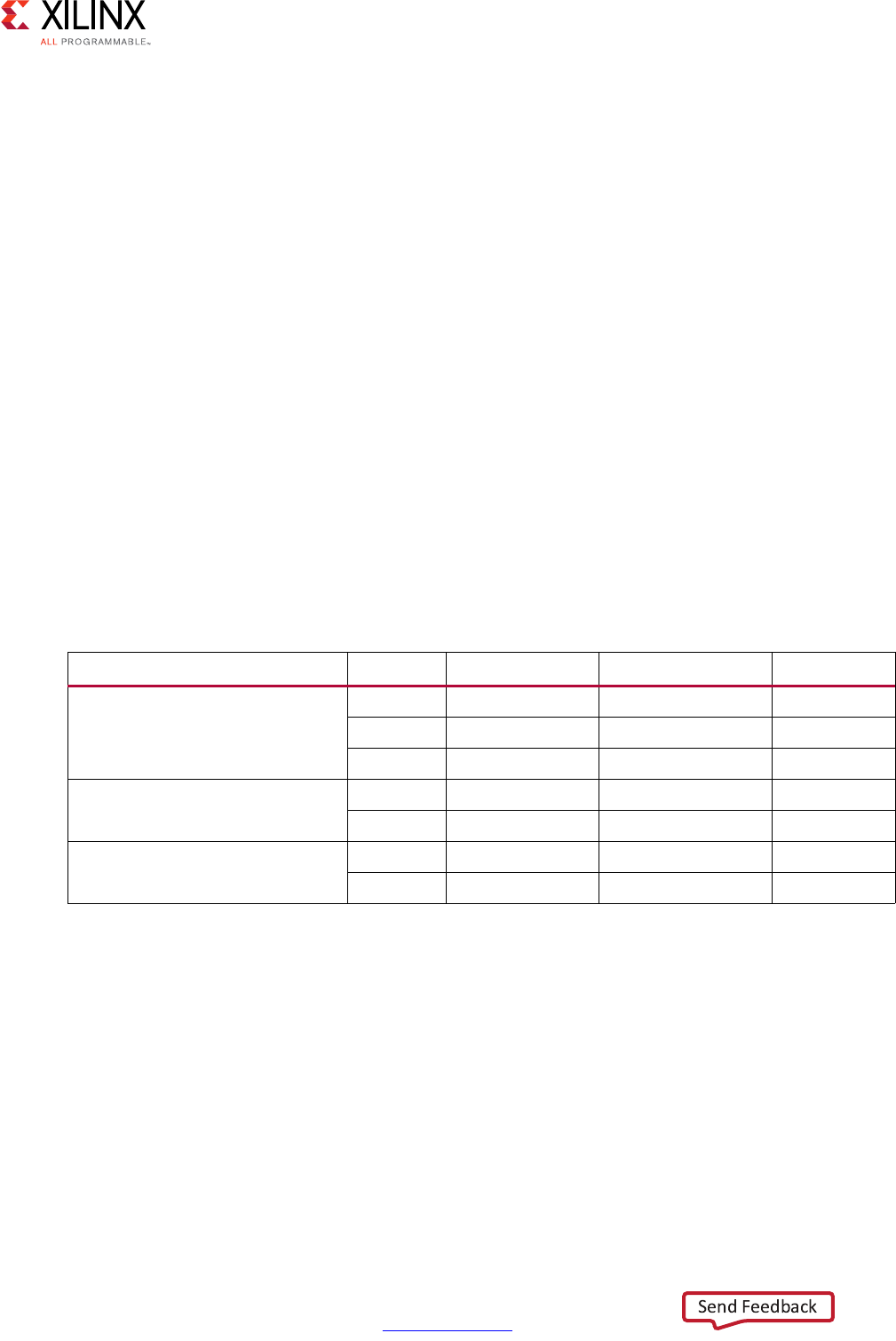
High-Level Synthesis 283
UG902 (v2017.1) April 5, 2017 www.xilinx.com
Chapter 2: High-Level Synthesis C Libraries
You can open these examples from the Vivado HLS Welcome screen:
1. Click Open Example Project.
2. In the Examples dialog box, expand Design Examples > linear_algebra >
implementation_targets.
Note: The Welcome Page appears when you invoke the Vivado HLS GUI. You can access it at any
time by selecting Help > Welcome.
To determine which optimization works best for your design, you can compare the
performance and utilization estimates for each solution using the Vivado HLS Compare
Reports feature. To compare the estimates, you must run synthesis for all of the project
solutions by selecting Solution > Run C Synthesis > All Solutions. Then, use the Compare
Reports toolbar button.
Cholesky
Implementation Controls
The following table summarizes the key factors that influence resource utilization, function
throughput (initiation interval), and function latency. The values of Low, Medium, and High
are relative to the other key factors.
Table 2-26: Cholesky Key Factor Summary
Key Factor Value Resources Throughput Latency
Architecture
(ARCH)
0Low Low High
1 Medium Medium Medium
2 High High Low
Inner loop pipelining
(INNER_II)
1 High High Low
>1 Low Low High
Inner loop unrolling
(UNROLL_FACTOR)
1Low Low High
>1 High High Low

High-Level Synthesis 284
UG902 (v2017.1) April 5, 2017 www.xilinx.com
Chapter 2: High-Level Synthesis C Libraries
Key Factors
Following is additional information about the key factors in the preceding table:
• Architecture
°0: Uses the lowest DSP utilization and lowest throughput.
°1: Uses higher DSP utilization but minimized memory utilization with increased
throughput. This value does not support inner loop unrolling to further increase
throughput.
°2: Uses highest DSP and memory utilization. This value supports inner loop
unrolling to improve overall throughput with a limited increase in DSP resources.
This is the most flexible architecture for design exploration.
• Inner loop pipelining
°>1: For ARCH 2, enables Vivado HLS to resource share and reduce the DSP
utilization. When using complex floating-point data types, setting the value to 2 or
4 significantly reduces DSP utilization.
• Inner loop unrolling
°For ARCH 2, duplicates the hardware required to implement the loop processing by
a specified factor, executes the corresponding number of loop iterations in parallel,
and increases throughput but also increases DSP and memory utilization.
Specifications
You can specify all factors using a configuration class derived from the following
hls::cholesky_traits base class by redefining the appropriate class member:
struct MY_CONFIG :
hls::cholesky_traits<LOWER_TRIANGULAR,ROWS_COLS_A,MAT_IN_T,MAT_OUT_T>{
static const int ARCH = 2;
static const int INNER_II = 2;
static const int UNROLL_FACTOR = 1;
};
The configuration class is supplied to the hls::cholesky_top function as a template
parameter as follows:
hls::cholesky_top<LOWER_TRIANGULAR,ROWS_COLS_A,MY_CONFIG,MAT_IN_T,MAT_OUT_T>(A,L);
The hls::cholesky function uses the following default configuration:
hls::cholesky<LOWER_TRIANGULAR,ROWS_COLS_A,MAT_IN_T,MAT_OUT_T>(A,L);
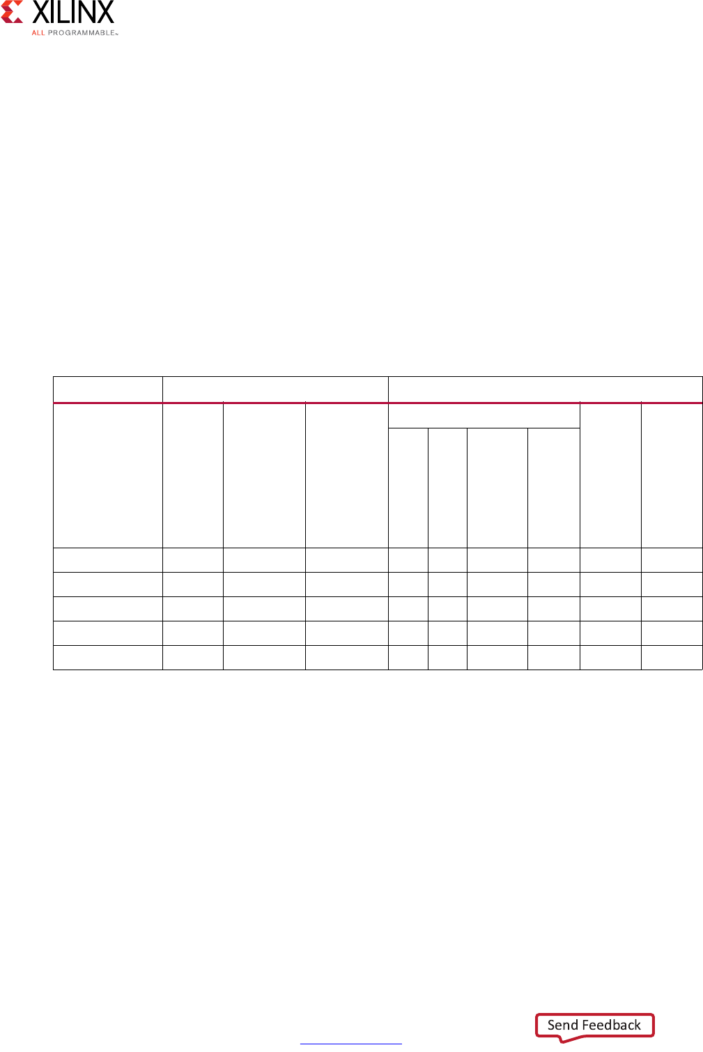
High-Level Synthesis 285
UG902 (v2017.1) April 5, 2017 www.xilinx.com
Chapter 2: High-Level Synthesis C Libraries
Examples
The following table shows example implementation solutions for the Cholesky function. The
performance metrics are generated using the Cholesky example project, which defines a
solution for each implementation target. The throughput and latency figures are based on
post-synthesis simulation.
The example project uses the following specifications:
• A input: 16x16 floating point complex matrix
• Synthesis wrapper: Local arrays for the input and output matrix
• Device: Kintex®-7 (xc7k160tfbg484-1)
• Nominal clock period: 4 ns
Table 2-27: Cholesky Implementation Targets
Solution Key Factor Performance Metric
Architecture
(ARCH)
Inner loop
pipelining
(INNER_II)
Inner loop
unrolling
(UNROLL_FACTOR)
Resources
Throughput cycles
Latency cycles
DSP
BRAM
FF
LUT
small 0 N/A N/A 8 8 5850 4271 33724 33724
balanced 1 N/A N/A 10 8 4582 3367 14466 14466
alt_balanced 2 4 1 10 6 5115 3552 15412 15412
fast 2 1 1 36 6 7820 5288 9322 9322
faster 2 1 2 72 12 12569 8494 8370 8370
Notes:
1. Bold row indicates the default configuration.
2. N/A indicates key factors that are not utilized or have a limited effect.
3. Values are representative only and are not intended to be exact.
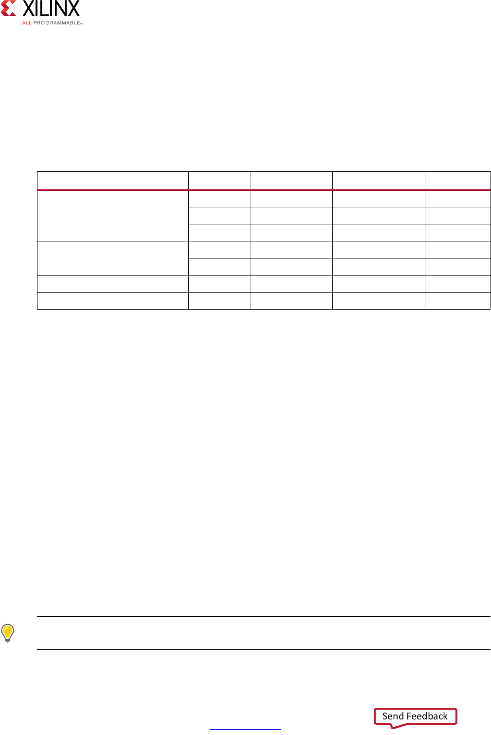
High-Level Synthesis 286
UG902 (v2017.1) April 5, 2017 www.xilinx.com
Chapter 2: High-Level Synthesis C Libraries
Cholesky Inverse and QR Inverse
Implementation Controls
The following table summarizes the key factors that influence resource utilization, function
throughput (initiation interval), and function latency. The values of Low, Medium, and High
are relative to the other key factors.
Key Factors
Following is additional information about the key factors shown in the preceding table:
• Sub-function implementation
°Utilizes the following sub-functions executed sequentially: Cholesky or QRF, back
substitution, and matrix multiply. The implementation selected for these
sub-functions determines the resource utilization and function throughput/latency
of the Inverse function.
• Back substitution inner and diagonal loop pipelining
°>1: Enables Vivado HLS to resource share and reduce the DSP utilization.
•DATAFLOW directive
°Pipelines sequential tasks, which increases the function throughput to an initiation
interval based on the maximum sub-function latency rather than the sum of the
individual sub-function latencies. The function throughput substantially increases
along with an increase in overall latency. Additional memory resources are required.
•INLINE directive
°Removes the sub-function hierarchy and allows Vivado HLS to better share
resources and can reduce DSP and memory utilization.
TIP: You can adjust the resources and throughput of the Inverse functions to meet specific requirements
by combining the DATAFLOW directive with the appropriate sub-function implementations.
Table 2-28: Inverse Key Factor Summary
Key Factor Value Resources Throughput Latency
Sub-function implementation
target (Cholesky/QRF and matrix
multiply)
Small Low Low High
Balanced Medium Medium Medium
Fast High High Low
Back substitution inner and
diagonal loop pipelining
1 High High Low
>1 Low Low High
DATAFLOW directive Yes Medium High High
INLINE directive Yes Low Low High

High-Level Synthesis 287
UG902 (v2017.1) April 5, 2017 www.xilinx.com
Chapter 2: High-Level Synthesis C Libraries
Specifications
The DATAFLOW directive is applied to the hls::cholesky_inverse_top or
hls::qr_inverse_top function as follows:
set_directive_dataflow "cholesky_inverse_top"
The INLINE directive is applied in the same manner:
set_directive_inline -recursive "cholesky_inverse_top"
You can specify the individual sub-function implementations using a configuration class
derived from the following hls::cholesky_inverse_traits or
hls::qr_inverse_traits base class by redefining the appropriate class member:
typedef hls::cholesky_inverse_traits<ROWS_COLS_A,
MAT_IN_T,
MAT_OUT_T> MY_DFLT_CFG;
struct MY_CONFIG : MY_DFLT_CFG {
struct CHOLESKY_TRAITS :
hls::cholesky_traits<false,
ROWS_COLS_A,
MAT_IN_T,
MY_DFLT_CFG::CHOLESKY_OUT> {
static const int ARCH = 1;
};
struct BACK_SUB_CONFIG :
hls::back_substitute_traits<ROWS_COLS_A,
MY_DFLT_CFG::CHOLESKY_OUT,
MY_DFLT_CFG::BACK_SUBSTITUTE_OUT> {
static const int INNER_II = 2;
static const int DIAG_II = 2;
};
struct MULTIPLIER_CONFIG :
hls::matrix_multiply_traits<hls::NoTranspose,
hls::ConjugateTranspose,
ROWS_COLS_A,
ROWS_COLS_A,
ROWS_COLS_A,
ROWS_COLS_A,
MY_DFLT_CFG::BACK_SUBSTITUTE_OUT,
MAT_OUT_T> {
static const int INNER_II = 2;
};
};
The configuration class is supplied to the hls::cholesky_inverse_top or
hls::qr_inverse_top function as a template parameter as follows:
hls::cholesky_inverse_top<ROWS_COLS_A,MY_CONFIG,MAT_IN_T,MAT_OUT_T>(A,INVERSE_A,inv
erse_OK);
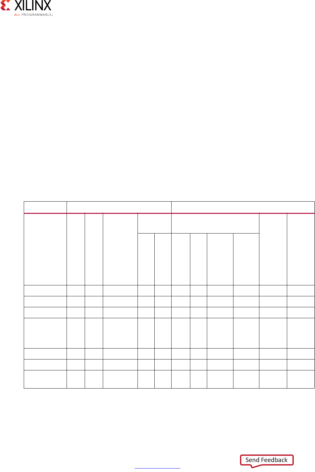
High-Level Synthesis 288
UG902 (v2017.1) April 5, 2017 www.xilinx.com
Chapter 2: High-Level Synthesis C Libraries
The hls::cholesky_inverse or hls::qr_inverse function uses the following
default configuration:
hls::cholesky_inverse<ROWS_COLS_A,MAT_IN_T,MAT_OUT_T>(A,INVERSE_A,inverse_OK);
Examples
The following table shows example implementation solutions for the Cholesky and matrix
multiply sub-functions. The performance metrics are generated using the Cholesky
Inverse example project, which defines a solution for each implementation target. The
throughput and latency figures are based on post-synthesis simulation.
The example projects use the following specifications:
• A input: 8x8 floating point complex matrix
• Synthesis wrapper: Local arrays for the input and output matrix
• Device: Kintex-7 (xc7k160tfbg484-1)
• Nominal clock period: 4 ns
Table 2-29: Cholesky Inverse Implementation Targets
Solution Key Factor Performance Metric
INLINE directive
DATAFLOW directive
Cholesky and Multiply
Target
Back
Subst. Resources
Throughput cycles
Latency cycles
DIAG_II
INNER_II
DSP
BRAM
FF
LUT
smaller ✓N/A Small 8 8 8 17 6786 5268 13972 13972
small N/A N/A Small 8 8 18 21 9924 6887 11762 11762
balanced N/A N/A Balanced 2 2 38 16 10625 7808 2181 10182
balanced_
high_
throughput
N/A ✓Balanced 2 2 38 26 10566 7708 5820 5820
default N/A N/A Default 1 1 66 16 13464 9286 4885 4885
fast N/A N/A Fast 1 1 92 18 16588 11179 4533 4533
fast_high_
throughput
N/A ✓Fast 1 1 92 28 16562 11112 1900 8428
Notes:
1. Bold row indicates the default configuration.
2. N/A indicates key factors that are not utilized or have a limited effect.
3. Values are representative only and are not intended to be exact.
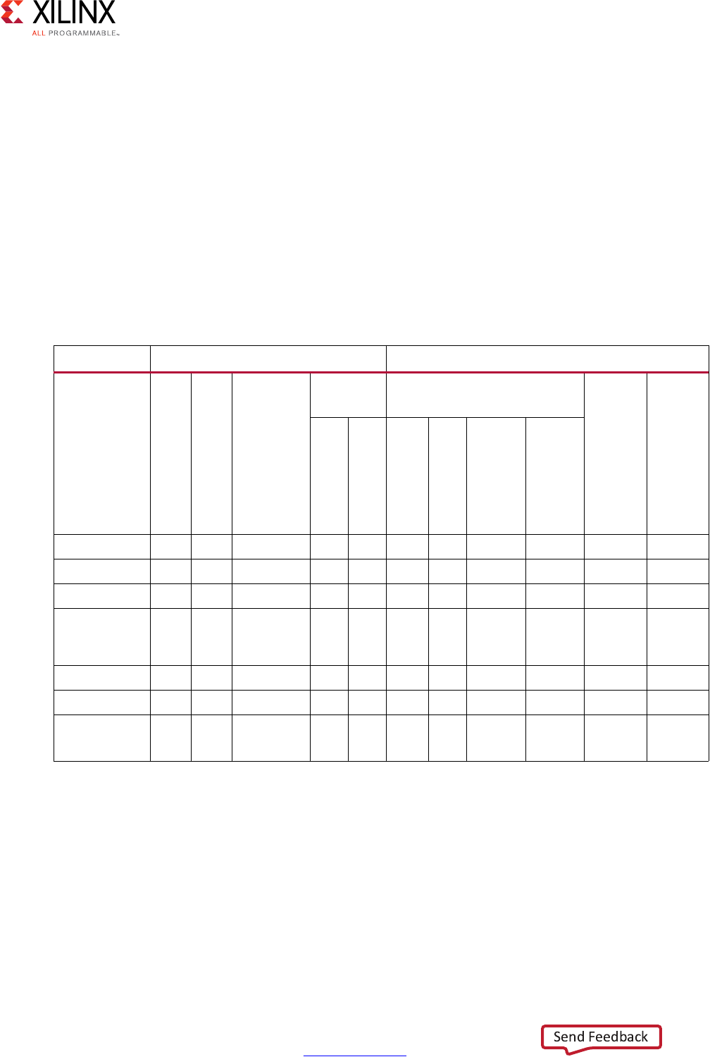
High-Level Synthesis 289
UG902 (v2017.1) April 5, 2017 www.xilinx.com
Chapter 2: High-Level Synthesis C Libraries
The following table shows example implementation solutions for the QRF and matrix
multiply sub-functions. The performance metrics are generated using the QR Inverse
example project, which defines a solution for each implementation target. The throughput
and latency figures are based on post-synthesis simulation.
The example projects use the following specifications:
• A input: 8x8 floating point complex matrix
• Synthesis wrapper: Local arrays for the input and output matrix
• Device: Kintex-7 (xc7k160tfbg484-1)
• Nominal clock period: 4 ns
Table 2-30: QRF Inverse Implementation Targets
Solution Key Factor Performance Metric
INLINE directive
DATAFLOW directive
QRF and Multiply
Target
Back
Subst. Resources
Throughput cycles
Latency cycles
DIAG_II
INNER_II
DSP
BRAM
FF
LUT
smaller ✓N/A Small 8 8 18 23 13530 9715 10734 10734
small N/A N/A Small 8 8 33 25 16249 11721 10705 10705
balanced N/A N/A Balanced 2 2 92 26 39436 21675 6277 6277
balanced_
high_
throughput
N/A ✓Balanced 2 2 92 38 39461 21653 2975 12458
default N/A N/A Default 1 1 110 26 41254 22532 5982 5982
fast N/A N/A Fast 1 1 146 26 45026 25471 5576 5576
fast_high_
throughput
N/A ✓Fast 1 1 146 38 45051 25449 2650 11066
Notes:
1. Bold row indicates the default configuration.
2. N/A indicates key factors that are not utilized or have a limited effect.
3. Values are representative only and are not intended to be exact.
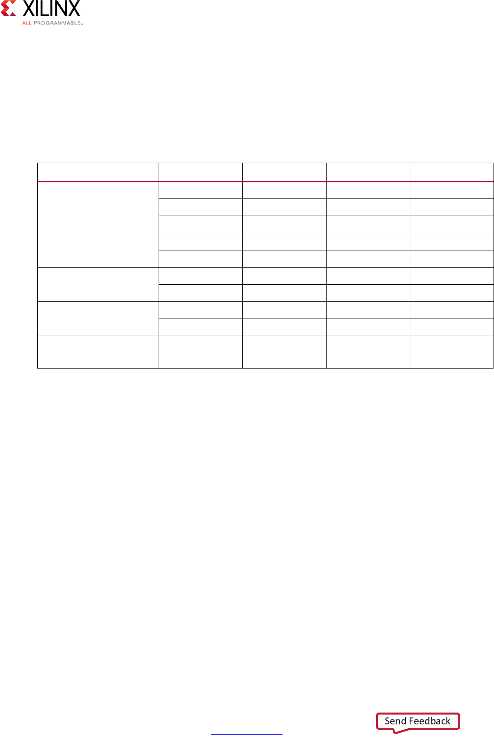
High-Level Synthesis 290
UG902 (v2017.1) April 5, 2017 www.xilinx.com
Chapter 2: High-Level Synthesis C Libraries
Matrix Multiply
Implementation Controls
The following table summarizes the key factors that influence resource utilization, function
throughput (initiation interval), and function latency. The values of Low, Medium, and High
are relative to the other key factors.
Key Factors
Following is additional information about the key factors in the preceding table:
• Architecture
The ARCH key factor selects the architecture based on the implementation data type.
°Floating-point data types
- 2: Ensures the inner accumulation loop achieves the maximum throughput with
an II of 1. This value supports inner loop partial unrolling, which improves
overall throughput with a limited increase in DSP resources.
- 3: Implements a fully unrolled inner accumulation loop, which uses the highest
number of DSP resources and highest throughput.
°Fixed-point data types
- 0: Uses the lowest resource utilization and lowest throughput.
- 2: Supports inner loop partial unrolling to improve overall throughput with a
limited increase in DSP resource.
Table 2-31: Matrix Multiply Key Factor Summary
Key Factor Value Resources Throughput Latency
Architecture
(ARCH)
2 (Floating Point) Low Low High
3 (Floating Point) High High Low
0 (Fixed Point) Low Low High
2 (Fixed Point) Medium Medium Medium
4 (Fixed Point) High High Low
Inner loop pipelining
(INNER_II)
1 High High Low
>1 Low Low High
Inner loop unrolling
(UNROLL_FACTOR)
1LowLowHigh
>1 High High Low
Resource directive
(RESOURCE)
LUTRAM Medium N/A N/A

High-Level Synthesis 291
UG902 (v2017.1) April 5, 2017 www.xilinx.com
Chapter 2: High-Level Synthesis C Libraries
- 4: Implements a fully unrolled inner accumulation loop, which uses the highest
number of DSP resources and highest throughput.
• Inner loop pipelining
°>1: When using complex floating-point data types, shares resources and reduces
DSP utilization. Setting the value to 2 or 4 significantly reduces DSP utilization.
• Inner loop unrolling
°For ARCH 2, duplicates the hardware required to implement the loop processing by
a specified factor, executes the corresponding number of loop iterations in parallel,
and increases throughput but also increases DSP and memory utilization.
°For ARCH 3 or 4, fully unrolls the accumulation loop.
• Resource directive
By default, Vivado HLS uses Block RAM to implement arrays.
°For ARCH 2, partially unrolling the accumulation loop results in Vivado HLS splitting
the sum_mult array across multiple Block RAM.
°When the partitioned size does not require using a Block RAM, use the RESOURCE
directive to specify a LUTRAM.
Specifications
Except for the RESOURCE directive, you can specify all factors using a configuration class
derived from the following hls::matrix_multiply_traits base class by redefining
the appropriate class member:
struct MY_CONFIG: hls::matrix_multiply_traits<hls::NoTranspose,
hls::NoTranspose,
A_ROWS,
A_COLS,
B_ROWS,
B_COLS,
MATRIX_T,
MATRIX_T>{
static const int ARCH = 2;
static const int INNER_II = 1;
static const int UNROLL_FACTOR = 2;
};
The configuration class is supplied to the hls::matrix_multiply_top function as a
template parameter as follows:
hls::matrix_multiply_top<hls::NoTranspose,hls::NoTranspose,A_ROWS,A_COLS,B_ROWS,B_C
OLS,C_ROWS,C_COLS,MY_CONFIG,MATRIX_T,MATRIX_T>(A,B,C);
The hls::matrix_multiply function uses the following default configuration:
hls::matrix_multiply<hls::NoTranspose,hls::NoTranspose,A_ROWS,A_COLS,B_ROWS,B_COLS,
C_ROWS,C_COLS,MATRIX_T,MATRIX_T>(A,B,C);
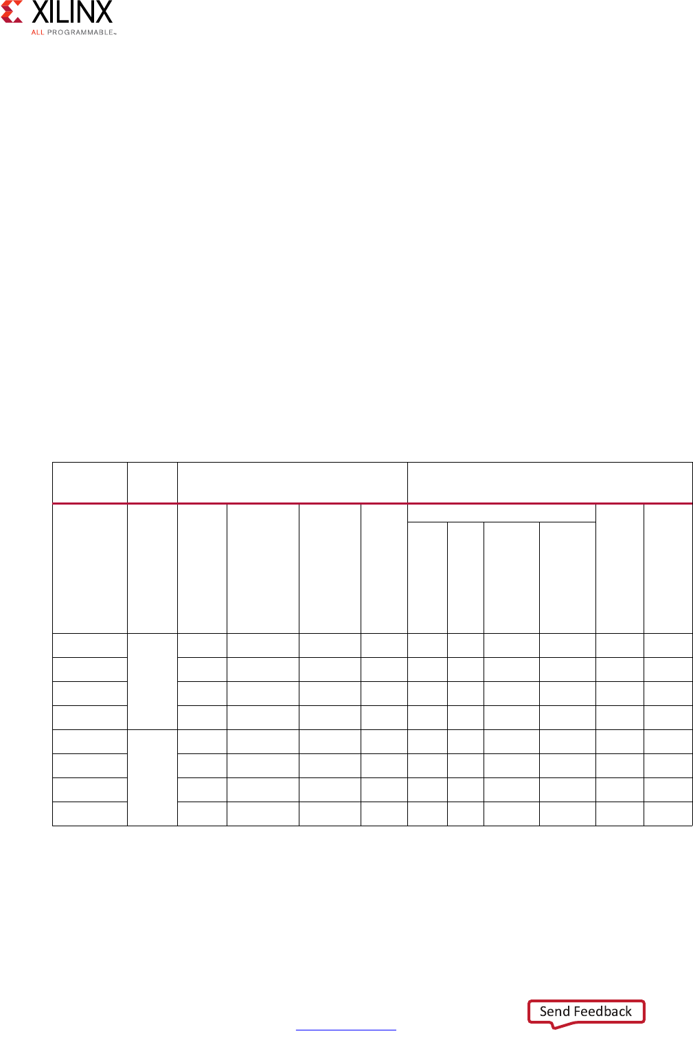
High-Level Synthesis 292
UG902 (v2017.1) April 5, 2017 www.xilinx.com
Chapter 2: High-Level Synthesis C Libraries
If you select ARCH 2, the RESOURCE directive is applied to the sum_mult array in function
hls::matrix_multiply_alt2 as follows:
set_directive_resource -core RAM_S2P_LUTRAM "matrix_multiply_alt2" sum_mult
Examples
The following table shows example implementation solutions for the matrix multiply
function. The performance metrics are generated using the Matrix Multiply Float
and Matrix Multiply Fixed example projects, which define a solution for each
implementation target. The throughput and latency values are based on post-synthesis
simulation.
The example projects use the following specifications:
• A and B inputs: 8x8 complex matrices
• Synthesis wrapper: Local arrays for the input and output matrix
• Device: Kintex-7 (xc7k160tfbg484-1)
• Nominal clock period: 4 ns
Table 2-32: Matrix Multiply Implementation Targets
Solution Data
type Key Factor Performance Metric
Architecture
(ARCH)
Inner loop
pipelining
(INNER_II)
Inner loop
unrolling
(INNER_UNROLL
RESOURCE
directive
Resources
Throughput cycles
Latency cycles
DSP
BRAM
FF
LUT
small Fixed 0 4 1 N/A 4 6 693 509 2194 2194
default 0 1 1 N/A 4 6 627 491 659 659
fast 2 1 4 ✓16 2 3164 1369 401 401
faster 4 N/A N/A N/A 32 2 2869 713 210 210
small Float 2 4 1 N/A 5 9 1401 948 2217 2217
default 2 1 1 N/A 20 10 3023 1993 683 683
fast 2 1 4 ✓40 2 7842 4885 425 425
faster 3 N/A N/A N/A 156 2 21680 12506 251 251
Notes:
1. Bold row indicates the default configuration.
2. N/A indicates key factors that are not utilized or have a limited effect.
3. Values are representative only and are not intended to be exact.
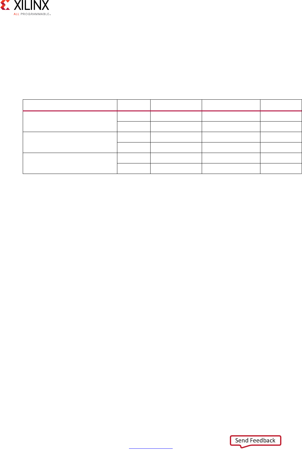
High-Level Synthesis 293
UG902 (v2017.1) April 5, 2017 www.xilinx.com
Chapter 2: High-Level Synthesis C Libraries
QRF
Implementation Controls
The following table summarizes the key factors that influence resource utilization, function
throughput (initiation interval), and function latency. The values of Low, Medium, and High
are relative to the other key factors.
Key Factors
Following is additional information about the key factors in the preceding table:
• Q and R update loop pipelining
°2: Sets the minimum achievable initiation interval (II) of 2, which satisfies the Q and
R matrix array requirement of two writes every iteration of the update loop.
°>2: Enables Vivado HLS to further resource share and reduce the DSP utilization.
With complex-floating point data types, setting the value to 4 or 8 significantly
reduces DSP utilization.
• Q and R update loop unrolling
°Duplicates the hardware required to implement the loop processing by a specified
factor, executes the corresponding number of loop iterations in parallel, and
increases throughput but also increases DSP and memory utilization.
• Rotation loop pipelining
°Enables Vivado HLS to resource share and reduce the DSP utilization.
Specifications
You can specify all factors using a configuration class derived from the following
hls::qrf_traits base class by redefining the appropriate class member:
struct MY_CONFIG : hls::qrf_traits<A_ROWS,A_COLS,MAT_IN_T,MAT_OUT_T>{
static const int CALC_ROT_II = 4;
static const int UPDATE_II= 4;
static const int UNROLL_FACTOR= 2;
};
Table 2-33: QRF Key Factor Summary
Key Factor Value Resources Throughput Latency
Q and R update loop pipelining
(UPDATE_II)
2 High High Low
>2 Low Low High
Q and R update loop unrolling
(UNROLL_FACTOR)
1Low Low High
>1 High High Low
Rotation loop pipelining
(CALC_ROT_II)
1 High High Low
>1 Low Low High
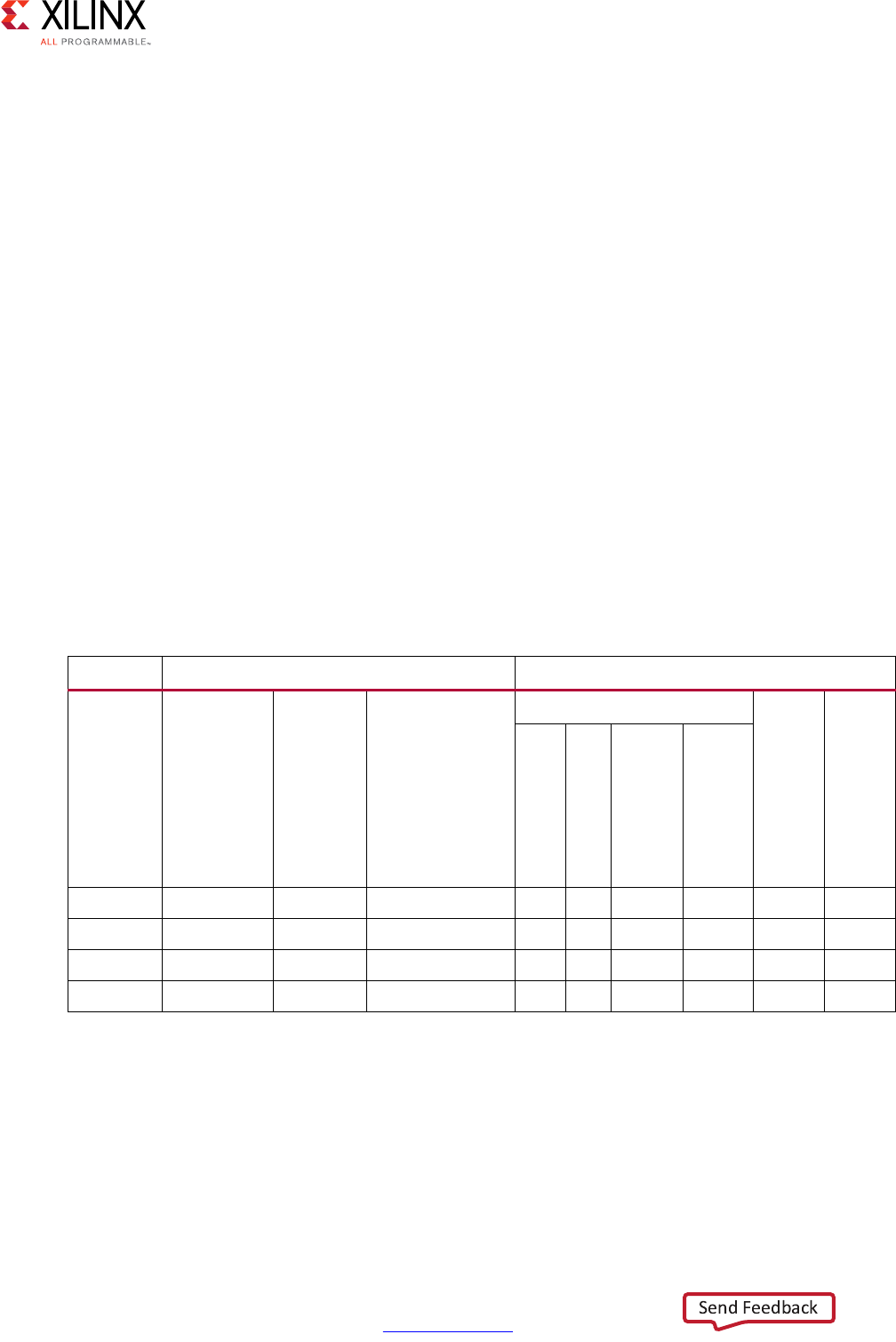
High-Level Synthesis 294
UG902 (v2017.1) April 5, 2017 www.xilinx.com
Chapter 2: High-Level Synthesis C Libraries
The configuration class is supplied to the hls::qrf_top function as a template parameter
as follows:
hls::qrf_top<TRANSPOSED_Q,A_ROWS,A_COLS,MY_CONFIG,MAT_IN_T,MAT_OUT_T>(A,Q,R);
The hls::qrf function uses the following default configuration:
hls::qrf<TRANSPOSED_Q,A_ROWS,A_COLS,MAT_IN_T,MAT_OUT_T>(A,Q,R);
Examples
The following table shows example implementation solutions for the QRF function. The
performance metrics are generated using the QRF example project, which defines a solution
for each implementation target. The throughput and latency figures are based on
post-synthesis simulation.
The example project uses the following specifications:
• A input: 16x16 floating-point complex matrix
• Synthesis wrapper: Local arrays for the input and output matrix
• Device: Kintex-7 (xc7k160tfbg484-1)
• Nominal clock period: 4 ns
Table 2-34: QRF Implementation Targets
Solution Key Factor Performance Metric
Rotation loop
pipelining
(CALC_ROT_II)
Q and R update loop
pipelining
(UPDATE_II)
Q and R update loop
unrolling
(UNROLL_FACTOR)
Resources
Throughput cycles
Latency cycles
DSP
BRAM
FF
LUT
small 8 8 N/A 23 14 12252 9203 25620 25620
balanced 1 4 1 54 14 32624 16825 16746 16746
fast 1 2 1 90 14 36396 19764 13116 13116
faster 1 2 2 162 22 46004 27043 11180 11180
Notes:
1. Bold row indicates the default configuration.
2. N/A indicates key factors that are not utilized or have a limited effect.
3. Values are representative only and are not intended to be exact.
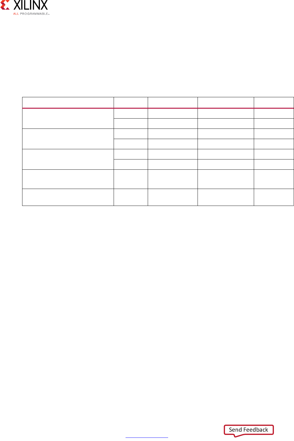
High-Level Synthesis 295
UG902 (v2017.1) April 5, 2017 www.xilinx.com
Chapter 2: High-Level Synthesis C Libraries
SVD
Implementation Controls
The following table summarizes the key factors that influence resource utilization, function
throughput (initiation interval), and function latency. The values of Low, Medium, and High
are relative to the other key factors.
Key Factors
Following is additional information about the key factors in the preceding table:
•ALLOCATION directive
°Limits the number of implemented 2x1 vector dot products. Vivado HLS schedules
the SVD function to use the specified number 2x1 vector dot product kernels.
Note: The SVD algorithm is computationally intensive, particularly for complex data types.
The ALLOCATION directive is the most effective method to balance resource utilization and
throughput.
• Off-diagonal loop pipelining
°4: Sets the minimum achievable initiation interval (II) of 4, which satisfies the S, U,
and V array requirement of four writes every iteration of the off-diagonal loop.
°>4: Enables Vivado HLS to further resource share and reduce the DSP utilization.
• Diagonal loop pipelining
°>1: Enables Vivado HLS to resource share.
Table 2-35: SVD Key Factor Summary
Key Factor Value Resources Throughput Latency
ALLOCATION directive
(vm2x1_base limit)
1Low Low High
>1 High High Low
Off-diagonal loop pipelining
(OFF_DIAG_II)
4 High High Low
>4 Low Low High
Diagonal loop pipelining
(DIAG_II)
1 High High Low
>1 Low Low High
Iterations
(NUM_SWEEP)
<10 N/A High Low
Reciprocal Square Root operator Combined
operator
Medium High Low

High-Level Synthesis 296
UG902 (v2017.1) April 5, 2017 www.xilinx.com
Chapter 2: High-Level Synthesis C Libraries
• Iterations
The SVD function uses the iterative two-sided Jacobi method.
°10: Sets the default number of iterations.
°<10: Maximizes the function throughput by setting the minimum number of
iterations that meets the desired performance.
• Reciprocal Square Root operator
°Ensures a much lower latency than the discrete operators.
Note: By default, Vivado HLS does not use the combined rsqrt operator but uses discrete
divide and sqrt operators. Selecting the -unsafe_math_optimizations compiler
option enables the use of the rsqrt operator.
Specifications
You can apply the ALLOCATION directive to the hls::svd_pairs function in combination
with the INLINE directive as follows:
set_directive_inline -off "vm2x1_base"
set_directive_allocation -limit 1 -type function "svd_pairs" vm2x1_base
You can select the -unsafe_math_optimizations compiler option as follows:
config_compile -unsafe_math_optimizations
You can specify all other factors using a configuration class derived from the following
hls::svd_traits base class by redefining the appropriate class member:
struct MY_CONFIG : hls::svd_traits<A_ROWS,A_COLS,MATRIX_IN_T,MATRIX_OUT_T>{
static const int NUM_SWEEPS = 6;
static const int DIAG_II = 4;
static const int OFF_DIAG_II = 4;
};
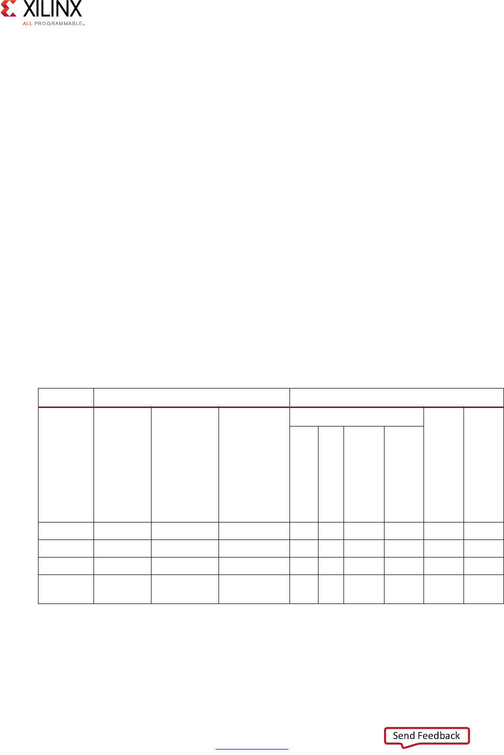
High-Level Synthesis 297
UG902 (v2017.1) April 5, 2017 www.xilinx.com
Chapter 2: High-Level Synthesis C Libraries
The configuration class is supplied to the hls::svd_top function as a template parameter
as follows:
hls::svd_top<A_ROWS,A_COLS,MY_CONFIG,MATRIX_IN_T,MATRIX_OUT_T>(A,S,U,V);
The hls::svd function uses the following default configuration:
hls::svd<A_ROWS,A_COLS,MATRIX_IN_T,MATRIX_OUT_T>(A,S,U,V);
Examples
The following table shows example implementation solutions for the SVD function. The
performance metrics are generated using the SVD example project, which defines a solution
for each implementation target. The throughput and latency figures are based on
post-synthesis simulation.
The example project uses the following specifications:
• A input: 8x8 floating point complex matrix
• Synthesis wrapper: Local arrays for the input and output matrix
• Device: Kintex-7 (xc7k160tfbg484-1)
• Nominal clock period: 4 ns
Note: You can set the DIAG_II and OFF_DIAG_II class members to different values.
Table 2-36: SVD Implementation Targets
Solution Key Factor Performance Metric
ALLOCATION
directive
(vm2x1_base limit)
Diagonal and
Off-diagonal loop
pipelining (DIAG_II /
OFF_DIAG_II1)
Iterations
(NUM_SWEEP)
Resources
Throughput cycles
Latency cycles
DSP
BRAM
FF
LUT
small 1 N/A 10 63 42 24467 21045 93464 93464
balanced None 8 10 108 42 32362 32080 68684 68684
fast None 4 10 207 42 45086 40905 63434 63434
fast_lower
_iterations
None 4 6 207 42 45055 40905 38150 38150
Notes:
1. Bold row indicates the default configuration.
2. N/A indicates key factors that are not utilized or have a limited effect.
3. Values are representative only and are not intended to be exact.
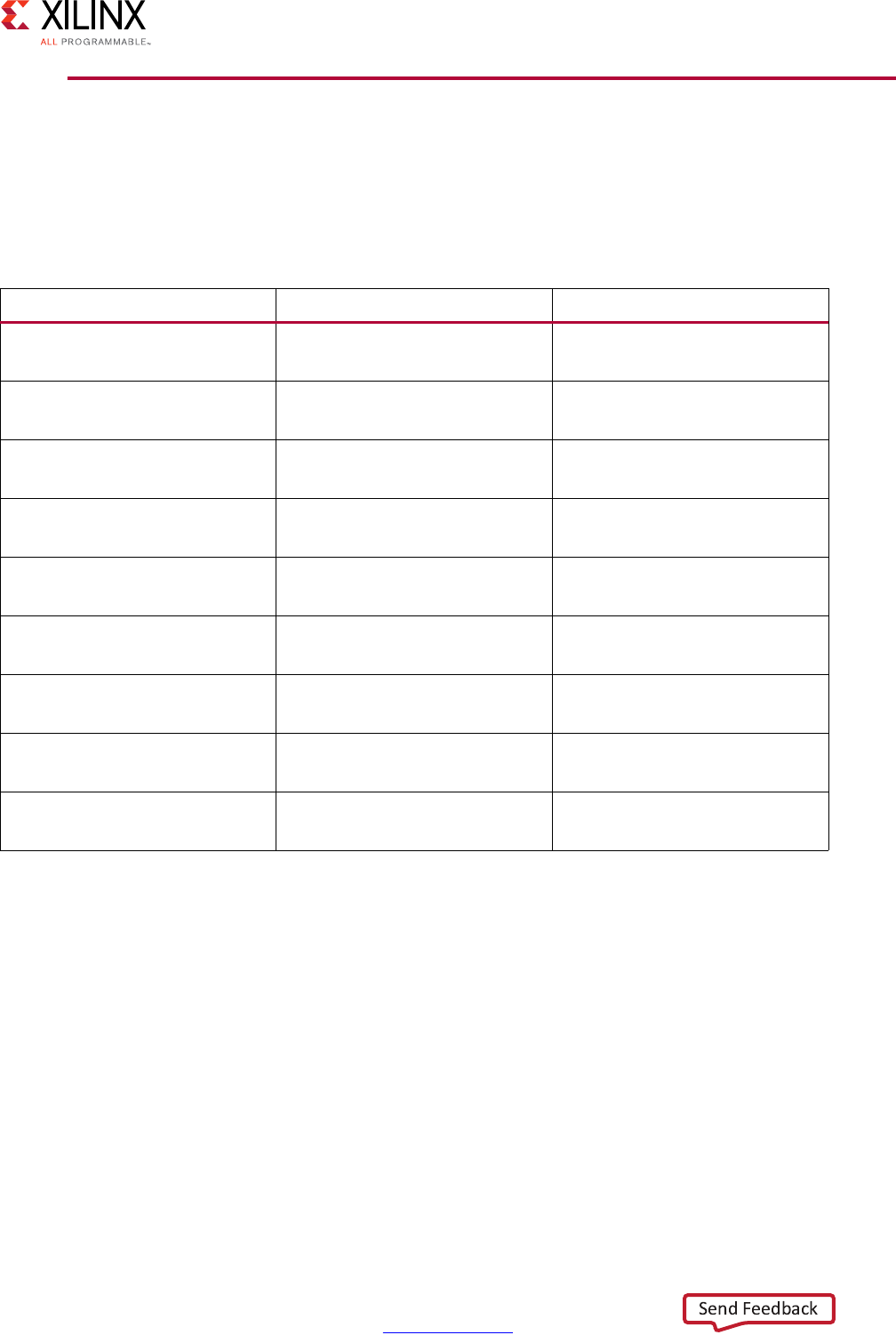
High-Level Synthesis 298
UG902 (v2017.1) April 5, 2017 www.xilinx.com
Chapter 2: High-Level Synthesis C Libraries
HLS DSP Library
The HLS DSP library contains building-block functions for DSP system modeling in C++
with an emphasis on functions used in SDR applications. The following table shows the
functions in the HLS DSP library.
Functions use the Vivado HLS fixed precision types ap_[u]int and ap_[u]fixed to
describe input and output data as needed. The functions have the minimum viable interface
type to maximize flexibility. For example, functions with a simple throughput model, such as
one sample out for one sample in, use pointer interfaces. Functions that perform a rate
change, such as viterbi_decoder, use the type hls::stream on the interfaces.
You can copy the existing library and make the interfaces more complex, such as creating
hls::streams for the pointer interfaces and AXI4-Stream interfaces for any function.
However, complex interfaces require more resources.
Vivado HLS provides most library elements as templated C++ classes, which are fully
described in the header file (hls_dsp.h) with constructor, destructor, and operator access
functions.
Table 2-37: HLS DSP Library
Function Data Type Implementation Style
atan2 input: std::complex< ap_fixed >
output: ap_ufixed
Synthesized
awgn input: ap_ufixed
output: ap_int
Synthesized
cmpy input: std::complex< ap_fixed >
output: std::complex< ap_fixed >
Synthesized
convolution_encoder input: ap_uint
output: ap_uint
Synthesized
nco input: ap_uint
output: std::complex< ap_int >
Synthesized
qam_demod input: std::complex< ap_int >
output: ap_uint
Synthesized
qam_mod input: ap_uint
output: std::complex< ap_int >
Synthesized
sqrt input: ap_ufixed, ap_int
output: ap_ufixed, ap_int
Synthesized
viterbi_decoder input: ap_uint
output: ap_uint
Synthesized

High-Level Synthesis 299
UG902 (v2017.1) April 5, 2017 www.xilinx.com
Chapter 2: High-Level Synthesis C Libraries
For a complete description of all DSP functions, see the HLS DSP Library Functions in
Chapter 4.
Using the DSP Library
You can reference the DSP functions using one of the following methods:
• Using scoped naming:
#include <hls_dsp.h>
static hls::awgn<output_width> my_awgn(seed);
my_awgn(snr, noise);
•Using the hls namespace:
#include <hls_dsp.h>
using namespace hls;
static awgn<output_width> my_awgn(seed);
my_awgn(snr, noise);
Functions in the DSP Library include synthesis directives as pragmas in the source code,
which guide Vivado HLS in synthesizing the function to meet typical requirements. The
functions are optimized for maximal throughput, which is the most common use case. For
example, arrays might be completely partitioned to ensure that an Initiation Interval of 1 is
achieved regardless of template parameter configuration.
You can remove existing optimizations or apply additional optimizations as follows:
• To apply optimizations on the DSP functions, open the header file hls_dsp.h in the
Vivado HLS GUI, and do one of the following:
°Press the Ctrl key and click #include “hls_dsp.h”
°Use the Explorer Pane and navigate to the file using the Includes folder.
• To add or remove an optimization as a directive, open the header file in the Information
pane, and use the Directives tab.
Note: If you add the optimization as a pragma, Vivado HLS places the optimization in the library
and applies it every time you add the header to a design. File write permissions might be
required to add the optimization as a pragma.
TIP: If you want to modify a function to modify its RTL implementation, look for comments in the
library source code with the prefix TIP, which indicate where it might be useful to place a pragma or
apply a directive.

High-Level Synthesis 300
UG902 (v2017.1) April 5, 2017 www.xilinx.com
Chapter 3
High-Level Synthesis Coding Styles
Introduction to Coding Styles
This chapter explains how various constructs of C, C++, SystemC, and OpenCL™ API C are
synthesized into an FPGA hardware implementation.
IMPORTANT: The term “C code” as used in this guide refers to code written in C, C++, SystemC, and
OpenCL API C, unless otherwise specifically noted.
The coding examples in this guide are part of the Vivado® HLS release. Access the coding
examples using one of the following methods:
• From the Welcome screen, click Open Example Project.
Note: To view the Welcome screen at any time, select Help > Welcome.
•In the examples/coding directory in the Vivado HLS installation area.
For more information, see Coding Examples in Chapter 1.
Unsupported C Constructs
While Vivado HLS supports a wide range of the C language, some constructs are not
synthesizable, or can result in errors further down the design flow. This section discusses
areas in which coding changes must be made for the function to be synthesized and
implemented in a device.
To be synthesized:
• The C function must contain the entire functionality of the design.
• None of the functionality can be performed by system calls to the operating system.
• The C constructs must be of a fixed or bounded size.
• The implementation of those constructs must be unambiguous.

High-Level Synthesis 301
UG902 (v2017.1) April 5, 2017 www.xilinx.com
Chapter 3: High-Level Synthesis Coding Styles
System Calls
System calls cannot be synthesized because they are actions that relate to performing some
task upon the operating system in which the C program is running.
Vivado HLS ignores commonly-used system calls that display only data and that have no
impact on the execution of the algorithm, such as printf() and fprintf(stdout,). In
general, calls to the system cannot be synthesized and should be removed from the
function before synthesis. Other examples of such calls are getc(), time(), sleep(), all
of which make calls to the operating system.
Vivado HLS defines the macro __SYNTHESIS__ when synthesis is performed. This allows
the __SYNTHESIS__ macro to exclude non-synthesizable code from the design.
Note: Only use the __SYNTHESIS__ macro in the code to be synthesized. Do not use this macro in the
test bench, because it is not obeyed by C simulation or C RTL co-simulation.
In the following code example, the intermediate results from a sub-function are saved to a
file on the hard drive. The macro __SYNTHESIS__ is used to ensure the non-synthesizable
files writes are ignored during synthesis.
#include "hier_func4.h"
int sumsub_func(din_t *in1, din_t *in2, dint_t *outSum, dint_t *outSub)
{
*outSum = *in1 + *in2;
*outSub = *in1 - *in2;
}
int shift_func(dint_t *in1, dint_t *in2, dout_t *outA, dout_t *outB)
{
*outA = *in1 >> 1;
*outB = *in2 >> 2;
}
void hier_func4(din_t A, din_t B, dout_t *C, dout_t *D)
{
dint_t apb, amb;
sumsub_func(&A,&B,&apb,&amb);
#ifndef __SYNTHESIS__
FILE *fp1;// The following code is ignored for synthesis
char filename[255];
sprintf(filename,Out_apb_%03d.dat,apb);
fp1=fopen(filename,w);
fprintf(fp1, %d \n, apb);
fclose(fp1);
#endif
shift_func(&apb,&amb,C,D);
}
Example 3-1: File Writes for Debug

High-Level Synthesis 302
UG902 (v2017.1) April 5, 2017 www.xilinx.com
Chapter 3: High-Level Synthesis Coding Styles
The __SYNTHESIS__ macro is a convenient way to exclude non-synthesizable code
without removing the code itself from the C function. Using such a macro does mean that
the C code for simulation and the C code for synthesis are now different.
CAUTION! If the __SYNTHESIS__ macro is used to change the functionality of the C code, it can
result in different results between C simulation and C synthesis. Errors in such code are inherently
difficult to debug. Do not use the __SYNTHESIS__ macro to change functionality.
Dynamic Memory Usage
Any system calls that manage memory allocation within the system, for example,
malloc(), alloc(), and free() are using resources that exist in the memory of the
operating system and are created and released during run time: to be able to synthesize a
hardware implementation the design must be fully self-contained, specifying all required
resources.
Memory allocation system calls must be removed from the design code before synthesis.
Because dynamic memory operations are used to define the functionality of the design,
they must be transformed into equivalent bounded representations. The following code
example shows how a design using malloc() can be transformed into a synthesizable
version and highlights two useful coding style techniques:
• The design does not use the __SYNTHESIS__ macro.
The user-defined macro NO_SYNTH is used to select between the synthesizable and
non-synthesizable versions. This ensures that the same code is simulated in C and
synthesized in Vivado HLS.
• The pointers in the original design using malloc() do not need to be rewritten to
work with fixed sized elements.
Fixed sized resources can be created and the existing pointer can simply be made to
point to the fixed sized resource. This technique can prevent manual re-coding of the
existing design.

High-Level Synthesis 303
UG902 (v2017.1) April 5, 2017 www.xilinx.com
Chapter 3: High-Level Synthesis Coding Styles
#include "malloc_removed.h"
#include <stdlib.h>
//#define NO_SYNTH
dout_t malloc_removed(din_t din[N], dsel_t width) {
#ifdef NO_SYNTH
long long *out_accum = malloc (sizeof(long long));
int* array_local = malloc (64 * sizeof(int));
#else
long long _out_accum;
long long *out_accum = &_out_accum;
int _array_local[64];
int* array_local = &_array_local[0];
#endif
int i,j;
LOOP_SHIFT:for (i=0;i<N-1; i++) {
if (i<width)
*(array_local+i)=din[i];
else
*(array_local+i)=din[i]>>2;
}
*out_accum=0;
LOOP_ACCUM:for (j=0;j<N-1; j++) {
*out_accum += *(array_local+j);
}
return *out_accum;
}
Example 3-2: Transforming malloc() to Fixed Resources
Because the coding changes here impact the functionality of the design, Xilinx does not
recommend using the __SYNTHESIS__ macro. Xilinx recommends that you perform the
following steps:
1. Add the user-defined macro NO_SYNTH to the code and modify the code.
2. Enable macro NO_SYNTH, execute the C simulation, and save the results.
3. Disable the macro NO_SYNTH, and execute the C simulation to verify that the results are
identical.
4. Perform synthesis with the user-defined macro disabled.
This methodology ensures that the updated code is validated with C simulation and that the
identical code is then synthesized.
As with restrictions on dynamic memory usage in C, Vivado HLS does not support (for
synthesis) C++ objects that are dynamically created or destroyed. This includes dynamic
polymorphism and dynamic virtual function calls.

High-Level Synthesis 304
UG902 (v2017.1) April 5, 2017 www.xilinx.com
Chapter 3: High-Level Synthesis Coding Styles
The following code cannot be synthesized because it creates a new function at run time.
Class A {
public:
virtual void bar() {…};
};
void fun(A* a) {
a->bar();
}
A* a = 0;
if (base)
a = new A();
else
a = new B();
foo(a);
Example 3-3: Unsynthesizable Code Coding Example
Pointer Limitations
General Pointer Casting
Vivado HLS does not support general pointer casting, but supports pointer casting between
native C types. For more information on pointer casting, see Example 3-34.
Pointer Arrays
Vivado HLS supports pointer arrays for synthesis, provided that each pointer points to a
scalar or an array of scalars. Arrays of pointers cannot point to additional pointers. For more
information on pointer arrays, see Example 3-33.
Function Pointers
Function pointers are not supported.
Recursive Functions
Recursive functions cannot be synthesized. This applies to functions that can form endless
recursion, where endless:
unsigned foo (unsigned n)
{
if (n == 0 || n == 1) return 1;
return (foo(n-2) + foo(n-1));
}

High-Level Synthesis 305
UG902 (v2017.1) April 5, 2017 www.xilinx.com
Chapter 3: High-Level Synthesis Coding Styles
Vivado HLS does not support tail recursion in which there is a finite number of function
calls.
unsigned foo (unsigned m, unsigned n)
{
if (m == 0) return n;
if (n == 0) return m;
return foo(n, m%n);
}
In C++, templates can implement tail recursion. C++ is addressed next.
Standard Template Libraries
Many of the C++ Standard Template Libraries (STLs) contain function recursion and use
dynamic memory allocation. For this reason, the STLs cannot be synthesized. The solution
with STLs is to create a local function with identical functionality that does not exhibit these
characteristics of recursion, dynamic memory allocation or the dynamic creation and
destruction of objects.
Note: Standard data types, such as std::complex, are supported for synthesis.
C Test Bench
The first step in the synthesis of any block is to validate that the C function is correct. This
step is performed by the test bench. Writing a good test bench can greatly increase your
productivity.
C functions execute in orders of magnitude faster than RTL simulations. Using C to develop
and validate the algorithm before synthesis is more productive than developing at the RTL.
• The key to taking advantage of C development times is to have a test bench that checks
the results of the function against known good results. Because the algorithm is known
to be correct, any code changes can be validated before synthesis.
• Vivado HLS reuses the C test bench to verify the RTL design. No RTL test bench needs
to be created when using Vivado HLS. If the test bench checks the results from the
top-level function, the RTL can be verified by simulation.
Note: To provide input arguments to the test bench, select Project > Project Settings, click
Simulation, and use the Input Arguments option. The test bench must not require the execution of
interactive user inputs. Vivado HLS GUI does not have a command console and cannot accept user
inputs while the test bench executes.
Xilinx recommends that you separate the top-level function for synthesis from the test
bench, and that you use header files. The following code example shows a design in which
the function hier_func calls two sub-functions:

High-Level Synthesis 306
UG902 (v2017.1) April 5, 2017 www.xilinx.com
Chapter 3: High-Level Synthesis Coding Styles
•sumsub_func performs addition and subtraction.
•shift_func performs shift.
The data types are defined in the header file (hier_func.h), which is also described:
#include "hier_func.h"
int sumsub_func(din_t *in1, din_t *in2, dint_t *outSum, dint_t *outSub)
{
*outSum = *in1 + *in2;
*outSub = *in1 - *in2;
}
int shift_func(dint_t *in1, dint_t *in2, dout_t *outA, dout_t *outB)
{
*outA = *in1 >> 1;
*outB = *in2 >> 2;
}
void hier_func(din_t A, din_t B, dout_t *C, dout_t *D)
{
dint_t apb, amb;
sumsub_func(&A,&B,&apb,&amb);
shift_func(&apb,&amb,C,D);
}
Example 3-4: Hierarchical Design Coding Example
The top-level function can contain multiple sub-functions. There can be only a single
top-level function for synthesis. To synthesize multiple functions, group them into a single
top-level function.
To synthesize function hier_func:
1. Add the file shown in Example 3-4 to a Vivado HLS project as a design file.
2. Specify the top-level function as hier_func.
After synthesis:
• The arguments to the top-level function (A, B, C, and D in Example 3-4) are synthesized
into RTL ports.
• The functions within the top-level (sumsub_func and shift_func in Example 3-4)
are synthesized into hierarchical blocks.
The header file (hier_func.h) in Example 3-4 shows how to use macros and how
typedef statements can make the code more portable and readable. Later sections show
how the typedef statement allows the types and therefore the bit-widths of the variables
to be refined for both area and performance improvements in the final FPGA
implementation.

High-Level Synthesis 307
UG902 (v2017.1) April 5, 2017 www.xilinx.com
Chapter 3: High-Level Synthesis Coding Styles
#ifndef _HIER_FUNC_H_
#define _HIER_FUNC_H_
#include <stdio.h>
#define NUM_TRANS 40
typedef int din_t;
typedef int dint_t;
typedef int dout_t;
void hier_func(din_t A, din_t B, dout_t *C, dout_t *D);
#endif
Example 3-5: Hierarchical Design Example Header File
The header file in this example includes some definitions (such as NUM_TRANS) that are not
required in the design file. These definitions are used by the test bench which also includes
the same header file.
The following code example shows the test bench for the design shown in Example 3-4.
#include "hier_func.h"
int main() {
// Data storage
int a[NUM_TRANS], b[NUM_TRANS];
int c_expected[NUM_TRANS], d_expected[NUM_TRANS];
int c[NUM_TRANS], d[NUM_TRANS];
//Function data (to/from function)
int a_actual, b_actual;
int c_actual, d_actual;
// Misc
int retval=0, i, i_trans, tmp;
FILE *fp;
// Load input data from files
fp=fopen(tb_data/inA.dat,r);
for (i=0; i<NUM_TRANS; i++){
fscanf(fp, %d, &tmp);
a[i] = tmp;
}
fclose(fp);
fp=fopen(tb_data/inB.dat,r);
for (i=0; i<NUM_TRANS; i++){
fscanf(fp, %d, &tmp);
b[i] = tmp;
}
fclose(fp);
// Execute the function multiple times (multiple transactions)
for(i_trans=0; i_trans<NUM_TRANS-1; i_trans++){

High-Level Synthesis 308
UG902 (v2017.1) April 5, 2017 www.xilinx.com
Chapter 3: High-Level Synthesis Coding Styles
//Apply next data values
a_actual = a[i_trans];
b_actual = b[i_trans];
hier_func(a_actual, b_actual, &c_actual, &d_actual);
//Store outputs
c[i_trans] = c_actual;
d[i_trans] = d_actual;
}
// Load expected output data from files
fp=fopen(tb_data/outC.golden.dat,r);
for (i=0; i<NUM_TRANS; i++){
fscanf(fp, %d, &tmp);
c_expected[i] = tmp;
}
fclose(fp);
fp=fopen(tb_data/outD.golden.dat,r);
for (i=0; i<NUM_TRANS; i++){
fscanf(fp, %d, &tmp);
d_expected[i] = tmp;
}
fclose(fp);
// Check outputs against expected
for (i = 0; i < NUM_TRANS-1; ++i) {
if(c[i] != c_expected[i]){
retval = 1;
}
if(d[i] != d_expected[i]){
retval = 1;
}
}
// Print Results
if(retval == 0){
printf( *** *** *** *** \n);
printf( Results are good \n);
printf( *** *** *** *** \n);
} else {
printf( *** *** *** *** \n);
printf( Mismatch: retval=%d \n, retval);
printf( *** *** *** *** \n);
}
// Return 0 if outputs are corre
return retval;
}
Example 3-6: Test Bench Example
High-Level Synthesis 309
UG902 (v2017.1) April 5, 2017 www.xilinx.com
Chapter 3: High-Level Synthesis Coding Styles
Productive Test Benches
Example 3-6 highlights some of the attributes of a productive test bench, such as:
• The top-level function for synthesis (hier_func) is executed for multiple transactions,
as defined by macro NUM_TRANS (specified in the header file Example 3-5). This
execution allows many different data values to be applied and verified. The test bench
is only as good as the variety of tests it performs.
• The function outputs are compared against known good values. The known good
values are read from a file in this example, but can also be computed as part of the test
bench.
• The return value of main() function is set to:
°Zero: Results are correct.
°Non-zero value: Results are incorrect.
Note: The test bench can return any non-zero value. A complex test bench can return
different values depending on the type of difference or failure. If the test bench returns a
non-zero value after C simulation or C/RTL co-simulation, Vivado HLS reports an error and
simulation fails.
RECOMMENDED: Because the system environment (for example, Linux, Windows, or Tcl) interprets the
return value of the main() function, Xilinx recommends that you constrain the return value to an 8-bit
range for portability and safety.
CAUTION! You are responsible for ensuring that the test bench checks the results. If the test bench does
not check the results but returns zero, Vivado HLS indicates that the simulation test passed even though
the results were not actually checked.
A test bench that exhibits these attributes quickly tests and validates any changes made to
the C functions before synthesis and is re-usable at RTL, allowing easier verification of the
RTL.
Design Files and Test Bench Files
Because Vivado HLS reuses the C test bench for RTL verification, it requires that the test
bench and any associated files be denoted as test bench files when they are added to the
Vivado HLS project.
Files associated with the test bench are any files that are:
• Accessed by the test bench; and
• Required for the test bench to operate correctly.

High-Level Synthesis 310
UG902 (v2017.1) April 5, 2017 www.xilinx.com
Chapter 3: High-Level Synthesis Coding Styles
Examples of such files include the data files inA.dat and inB.dat in Example 3-6. You
must add these to the Vivado HLS project as test bench files.
The requirement for identifying test bench files in a Vivado HLS project does not require
that the design and test bench to be in separate files (although separate files are
recommended).
The same design from Example 3-4 is repeated in Example 3-7. The only difference is that
the top-level function is renamed hier_func2, to differentiate the examples.
Using the same header file and test bench (other than the change from hier_func to
hier_func2), the only changes required in Vivado HLS to synthesize function
sumsub_func as the top-level function are:
•Set sumsub_func as the top-level function in the Vivado HLS project.
• Add the file in Example 3-7 as both a design file and project file. The level above
sumsub_func (function hier_func2) is now part of the test bench. It must be
included in the RTL simulation.
Even though function sumsub_func is not explicitly instantiated inside the main()
function, the remainder of the functions (hier_func2 and shift_func) confirm that it is
operating correctly, and thus is part of the test bench.
#include "hier_func2.h"
int sumsub_func(din_t *in1, din_t *in2, dint_t *outSum, dint_t *outSub)
{
*outSum = *in1 + *in2;
*outSub = *in1 - *in2;
}
int shift_func(dint_t *in1, dint_t *in2, dout_t *outA, dout_t *outB)
{
*outA = *in1 >> 1;
*outB = *in2 >> 2;
}
void hier_func2(din_t A, din_t B, dout_t *C, dout_t *D)
{
dint_t apb, amb;
sumsub_func(&A,&B,&apb,&amb);
shift_func(&apb,&amb,C,D);
}
Example 3-7: New Top-Level Design

High-Level Synthesis 311
UG902 (v2017.1) April 5, 2017 www.xilinx.com
Chapter 3: High-Level Synthesis Coding Styles
Combining Test Bench and Design Files
You can also include the design and test bench into a single design file. Example 3-8 has the
same functionality as Example 3-4 through Example 3-6, except that everything is captured
in a single file. Function hier_func is renamed hier_func3 to ensure that the examples
are unique.
IMPORTANT: If the test bench and design are in a single file, you must add the file to a Vivado HLS
project as both a design file and a test bench file.
#include <stdio.h>
#define NUM_TRANS 40
typedef int din_t;
typedef int dint_t;
typedef int dout_t;
int sumsub_func(din_t *in1, din_t *in2, dint_t *outSum, dint_t *outSub)
{
*outSum = *in1 + *in2;
*outSub = *in1 - *in2;
}
int shift_func(dint_t *in1, dint_t *in2, dout_t *outA, dout_t *outB)
{
*outA = *in1 >> 1;
*outB = *in2 >> 2;
}
void hier_func3(din_t A, din_t B, dout_t *C, dout_t *D)
{
dint_t apb, amb;
sumsub_func(&A,&B,&apb,&amb);
shift_func(&apb,&amb,C,D);
}
int main() {
// Data storage
int a[NUM_TRANS], b[NUM_TRANS];
int c_expected[NUM_TRANS], d_expected[NUM_TRANS];
int c[NUM_TRANS], d[NUM_TRANS];
//Function data (to/from function)
int a_actual, b_actual;
int c_actual, d_actual;
// Misc
int retval=0, i, i_trans, tmp;
FILE *fp;
// Load input data from files
fp=fopen(tb_data/inA.dat,r);
for (i=0; i<NUM_TRANS; i++){
fscanf(fp, %d, &tmp);

High-Level Synthesis 312
UG902 (v2017.1) April 5, 2017 www.xilinx.com
Chapter 3: High-Level Synthesis Coding Styles
a[i] = tmp;
}
fclose(fp);
fp=fopen(tb_data/inB.dat,r);
for (i=0; i<NUM_TRANS; i++){
fscanf(fp, %d, &tmp);
b[i] = tmp;
}
fclose(fp);
// Execute the function multiple times (multiple transactions)
for(i_trans=0; i_trans<NUM_TRANS-1; i_trans++){
//Apply next data values
a_actual = a[i_trans];
b_actual = b[i_trans];
hier_func3(a_actual, b_actual, &c_actual, &d_actual);
//Store outputs
c[i_trans] = c_actual;
d[i_trans] = d_actual;
}
// Load expected output data from files
fp=fopen(tb_data/outC.golden.dat,r);
for (i=0; i<NUM_TRANS; i++){
fscanf(fp, %d, &tmp);
c_expected[i] = tmp;
}
fclose(fp);
fp=fopen(tb_data/outD.golden.dat,r);
for (i=0; i<NUM_TRANS; i++){
fscanf(fp, %d, &tmp);
d_expected[i] = tmp;
}
fclose(fp);
// Check outputs against expected
for (i = 0; i < NUM_TRANS-1; ++i) {
if(c[i] != c_expected[i]){
retval = 1;
}
if(d[i] != d_expected[i]){
retval = 1;
}
}
// Print Results
if(retval == 0){
printf( *** *** *** *** \n);
printf( Results are good \n);
printf( *** *** *** *** \n);
} else {
printf( *** *** *** *** \n);
printf( Mismatch: retval=%d \n, retval);
printf( *** *** *** *** \n);

High-Level Synthesis 313
UG902 (v2017.1) April 5, 2017 www.xilinx.com
Chapter 3: High-Level Synthesis Coding Styles
}
// Return 0 if outputs are correct
return retval;
}
Example 3-8: Test Bench and Top-Level Design
OpenCL API C Test Benches
Vivado HLS synthesizes an OpenCL API C kernel. However, it cannot use the remaining
OpenCL API C code, typically referred to as the host code, as the design test bench. Instead,
Vivado HLS uses a standard C test bench to verify the OpenCL API C kernel.
Following are the primary advantages of using a test bench:
• Confirms the correct operation of the OpenCL API C kernel
• Automatically verifies the output RTL after synthesis
Use the following methodology to create an OpenCL API C test bench:
1. Create a standard C test bench with top-level function main().
2. Create input stimuli to verify the operation of the OpenCL API C kernel.
3. Use API function hls_run_kernel() to execute the OpenCL API C kernel.
4. Check the output results against known good values. If the output is correct, the test
bench returns a value of 0 to main().
The following example shows this methodology. This OpenCL API C kernel code shows a
vector addition design where two arrays of data are summed into a third. The required size
of the work group is 16, that is, this kernel must execute a minium of 16 times to produce a
valid result.
#include <clc.h>
// For VHLS OpenCL C kernels, the full work group is synthesized
__kernel void __attribute__ ((reqd_work_group_size(16, 1, 1)))
vadd(__global int* a,
__global int* b,
__global int* c)
{
int idx = get_global_id(0);
c[idx] = a[idx] + b[idx];
}

High-Level Synthesis 314
UG902 (v2017.1) April 5, 2017 www.xilinx.com
Chapter 3: High-Level Synthesis Coding Styles
The following C test bench example is used to verify the preceding example. The following
code is similar to any other C test bench except that it includes the API function
hls_run_kernel. Vivado HLS provides the following function signature to execute the
OpenCL API C kernel:
void hls_run_kernel(
const char *KernelName,
ScalarType0 *Arg0, int size0,
ScalarType1 *Arg1, int size1, …)
Where:
• Arg0 is the first argument of the OpenCL API C kernel.
• ScalarType0 is the type of the first argument of the OpenCL API C kernel.
• Size0 is the number of data samples to be read or written.
The number of arguments used in the API must match the number of arguments in the
OpenCL API C kernel. The example design vadd includes three arguments (a, b and c) that
read or write 16 data values. The following test bench verifies this function:
#define LENGTH 16
int main(int argc, char** argv)
{
int errors=0, i;
int a[LENGTH];
int b[LENGTH];
int hw_c[LENGTH];
int swref_c[LENGTH];
// Create input stimuli and compute the expected result
for(i = 0; i < LENGTH; i++) {
a[i] = i;
b[i] = i;
swref_c[i]= a[i] + b[i];
hw_c[i] = 0;
}
// Call the OpenCL C simulation run kernel
//
hls_run_kernel("vadd", a, LENGTH, b, LENGTH, hw_c, LENGTH);
// Check the results against the expected results
for (i=0; i<LENGTH; i++) {
int diff = hw_c[i] != swref_c[i];
if(diff) {
errors+=diff;
}
}
printf("There are %d error(s) -> test %s\n", errors, errors ? "FAILED" : "PASSED");
// Return a 0 if the results are correct
return errors;
}

High-Level Synthesis 315
UG902 (v2017.1) April 5, 2017 www.xilinx.com
Chapter 3: High-Level Synthesis Coding Styles
TIP: Vivado HLS provides OpenCL API C project examples. For an explanation of each design example,
see Table 1-5.
Functions
The top-level function becomes the top level of the RTL design after synthesis.
Sub-functions are synthesized into blocks in the RTL design.
IMPORTANT: The top-level function cannot be a static function.
After synthesis, each function in the design has its own synthesis report and RTL HDL file
(Verilog and VHDL).
Inlining functions
Sub-functions can optionally be inlined to merge their logic with the logic of the
surrounding function. While inlining functions can result in better optimizations, it can also
increase run time. More logic and more possibilities must be kept in memory and analyzed.
TIP: Vivado HLS may perform automatic inlining of small functions. To disable automatic inlining of a
small function, set the inline directive to off for that function.
If a function is inlined, there is no report or separate RTL file for that function. The logic and
loops are merged with the function above it in the hierarchy.
Impact of Coding Style
The primary impact of a coding style on functions is on the function arguments and
interface.
If the arguments to a function are sized accurately, Vivado HLS can propagate this
information through the design. There is no need to create arbitrary precision types for
every variable. In the following example, two integers are multiplied, but only the bottom
24 bits are used for the result.
#include "ap_cint.h"
int24 foo(int x, int y) {
int tmp;
tmp = (x * y);
return tmp
}

High-Level Synthesis 316
UG902 (v2017.1) April 5, 2017 www.xilinx.com
Chapter 3: High-Level Synthesis Coding Styles
When this code is synthesized, the result is a 32-bit multiplier with the output truncated to
24-bit.
If the inputs are correctly sized to 12-bit types (int12) as shown in the following code
example, the final RTL uses a 24-bit multiplier.
#include "ap_cint.h"
typedef int12 din_t;
typedef int24 dout_t;
dout_t func_sized(din_t x, din_t y) {
int tmp;
tmp = (x * y);
return tmp
}
Example 3-9: Sizing Function Arguments
Using arbitrary precision types for the two function inputs is enough to ensure Vivado HLS
creates a design using a 24-bit multiplier. The 12-bit types are propagated through the
design. Xilinx recommends that you correctly size the arguments of all functions in the
hierarchy.
In general, when variables are driven directly from the function interface, especially from
the top-level function interface, they can prevent some optimizations from taking place. A
typical case of this is when an input is used as the upper limit for a loop index.
Loops
Loops provide a very intuitive and concise way of capturing the behavior of an algorithm
and are used often in C code. Loops are very well supported by synthesis: loops can be
pipelined, unrolled, partially unrolled, merged and flattened.
The optimizations unroll, partially unroll, flatten and merge effectively make changes to the
loop structure, as if the code was changed. These optimizations ensure limited coding
changes are required when optimizing loops. Some optimizations can be applied only in
certain conditions. Some coding changes might be required.
RECOMMENDED: Avoid use of global variables for loop index variables, as this can inhibit some
optimizations.

High-Level Synthesis 317
UG902 (v2017.1) April 5, 2017 www.xilinx.com
Chapter 3: High-Level Synthesis Coding Styles
Variable Loop Bounds
Some of the optimizations that Vivado HLS can apply are prevented when the loop has
variable bounds. In the following code example, the loop bounds are determined by
variable width, which is driven from a top-level input. In this case, the loop is considered
to have variables bounds, because Vivado HLS cannot know when the loop will complete.
#include "ap_cint.h"
#define N 32
typedef int8 din_t;
typedef int13 dout_t;
typedef uint5 dsel_t;
dout_t code028(din_t A[N], dsel_t width) {
dout_t out_accum=0;
dsel_t x;
LOOP_X:for (x=0;x<width; x++) {
out_accum += A[x];
}
return out_accum;
}
Example 3-10: Variable Loop Bounds
Attempting to optimize the design in Example 3-10 reveals the issues created by variable
loop bounds.
The first issue with variable loop bounds is that they prevent Vivado HLS from determining
the latency of the loop. Vivado HLS can determine the latency to complete one iteration of
the loop, but because it cannot statically determine the exact value of variable width, it does
not know how many iteration are performed and thus cannot report the loop latency (the
number of cycles to completely execute every iteration of the loop).
When variable loop bounds are present, Vivado HLS reports the latency as a question mark
(?) instead of using exact values. The following shows the result after synthesis of
Example 3-10.
+ Summary of overall latency (clock cycles):
* Best-case latency: ?
* Worst-case latency: ?
+ Summary of loop latency (clock cycles):
+ LOOP_X:
* Trip count: ?
* Latency: ?
Another issue with variable loop bounds is that the performance of the design is unknown.

High-Level Synthesis 318
UG902 (v2017.1) April 5, 2017 www.xilinx.com
Chapter 3: High-Level Synthesis Coding Styles
The two ways to overcome this issue are:
• Use the Tripcount directive. The details on this approach are explained here.
• Use an assert macro in the C code. for more information, see C++ Classes and
Templates.
The tripcount directive allows a minimum and/or maximum tripcount to be specified
for the loop. The tripcount is the number of loop iterations. If a maximum tripcount of 32 is
applied to LOOP_X in Example 3-10, the report is updated to the following:
+ Summary of overall latency (clock cycles):
* Best-case latency: 2
* Worst-case latency: 34
+ Summary of loop latency (clock cycles):
+ LOOP_X:
* Trip count: 0 ~ 32
* Latency: 0 ~ 32
Tripcount directive has no impact on the results of synthesis, only reporting. The
user-provided values for the Tripcount directive are used only for reporting. The Tripcount
value allows Vivado HLS to report number in the report, allowing the reports from different
solutions to be compared. To have this same loop-bound information used for synthesis,
the C code must be updated. For more information, see C++ Classes and Templates.
Tripcount directives have no impact on the results of synthesis, only reporting.
The next steps in optimizing Example 3-10 for a lower initiation interval are:
• Unroll the loop and allow the accumulations to occur in parallel.
• Partition the array input, or the parallel accumulations are limited, by a single memory
port.
If these optimizations are applied, the output from Vivado HLS highlights the most
significant issue with variable bound loops:
@W [XFORM-503] Cannot unroll loop 'LOOP_X' in function 'code028': cannot completely
unroll a loop with a variable trip count.
Because variable bounds loops cannot be unrolled, they not only prevent the unroll
directive being applied, they also prevent pipelining of the levels above the loop.
IMPORTANT: When a loop or function is pipelined, Vivado HLS unrolls all loops in the hierarchy below
the function or loop. If there is a loop with variable bounds in this hierarchy, it prevents pipelining.
The solution to loops with variable bounds is to make the number of loop iteration a fixed
value with conditional executions inside the loop. The code from Example 3-10 can be
rewritten as shown in the following code example. Here, the loop bounds are explicitly set
to the maximum value of variable width and the loop body is conditionally executed.

High-Level Synthesis 319
UG902 (v2017.1) April 5, 2017 www.xilinx.com
Chapter 3: High-Level Synthesis Coding Styles
#include "ap_cint.h"
#define N 32
typedef int8 din_t;
typedef int13 dout_t;
typedef uint5 dsel_t;
dout_t loop_max_bounds(din_t A[N], dsel_t width) {
dout_t out_accum=0;
dsel_t x;
LOOP_X:for (x=0;x<N; x++) {
if (x<width) {
out_accum += A[x];
}
}
return out_accum;
}
Example 3-11: Variable Loop Bounds Rewritten
The for-loop (LOOP_X) in Example 3-11 can be unrolled. Because the loop has fixed upper
bounds, Vivado HLS knows how much hardware to create. There are N(32) copies of the
loop body in the RTL design. Each copy of the loop body has conditional logic associated
with it and is executed depending on the value of variable width.
Loop Pipelining
When pipelining loops, the most optimum balance between area and performance is
typically found by pipelining the inner most loop. This is also results in the fastest run time.
The following code example demonstrates the trade-offs when pipelining loops and
functions.
#include "loop_pipeline.h"
dout_t loop_pipeline(din_t A[N]) {
int i,j;
static dout_t acc;
LOOP_I:for(i=0; i < 20; i++){
LOOP_J: for(j=0; j < 20; j++){
acc += A[i] * j;
}
}
return acc;
}
Example 3-12: Loop Pipeline

High-Level Synthesis 320
UG902 (v2017.1) April 5, 2017 www.xilinx.com
Chapter 3: High-Level Synthesis Coding Styles
If the inner-most (LOOP_J) is pipelined, there is one copy of LOOP_J in hardware, (a single
multiplier). Vivado HLS automatically flattens the loops when possible, as in this case, and
effectively creates a new single loop of 20*20 iterations. Only 1 multiplier operation and 1
array access need to be scheduled, then the loop iterations can be scheduled as single
loop-body entity (20x20 loop iterations).
TIP: When a loop or function is pipelined, any loop in the hierarchy below the loop or function being
pipelined must be unrolled.
If the outer-loop (LOOP_I) is pipelined, inner-loop (LOOP_J) is unrolled creating 20 copies
of the loop body: 20 multipliers and 20 array accesses must now be scheduled. Then each
iteration of LOOP_I can be scheduled as a single entity.
If the top-level function is pipelined, both loops must be unrolled: 400 multipliers and 400
arrays accessed must now be scheduled. It is very unlikely that Vivado HLS will produce a
design with 400 multiplications because in most designs data dependencies often prevent
maximal parallelism, for example, in this case, even if a dual-port RAM is used for A[N] the
design can only access two values of A[N] in any clock cycle.
The concept to appreciate when selecting at which level of the hierarchy to pipeline is to
understand that pipelining the inner-most loop gives the smallest hardware with generally
acceptable throughput for most applications. Pipelining the upper-levels of the hierarchy
unrolls all sub-loops and can create many more operations to schedule (which could impact
run time and memory capacity), but typically gives the highest performance design in terms
of throughput and latency.
To summarize the above options:
• Pipeline LOOP_J
Latency is approximately 400 cycles (20x20) and requires less than 100 LUTs and
registers (the I/O control and FSM are always present).
• Pipeline LOOP_I
Latency is approximately 20 cycles but requires a few hundred LUTs and registers. About
20 times the logic as first option, minus any logic optimizations that can be made.
• Pipeline function loop_pipeline
Latency is approximately 10 (20 dual-port accesses) but requires thousands of LUTs and
registers (about 400 times the logic of the first option minus any optimizations that can
be made).

High-Level Synthesis 321
UG902 (v2017.1) April 5, 2017 www.xilinx.com
Chapter 3: High-Level Synthesis Coding Styles
Imperfect Nested Loops
When the inner-loop of a loop hierarchy is pipelined, Vivado HLS flattens the nested loops,
to reduce latency and improve overall throughput by removing any cycles caused by loop
transitioning (the checks performed on the loop index when entering and exiting loops).
Such checks can result in a clock delay when transitioning from one loop to the next (entry
and/or exit).
Imperfect loop nests, or the inability to flatten loop them, results in additional clock cycles
to enter and exit the loops. When the design contains nested loops, analyze the results to
ensure as many nested loops as possible have been flattened: review the log file or look in
the synthesis report for cases, as shown above, where the loop labels have been merged
(LOOP_I and LOOP_J are now reported as LOOP_I_LOOP_J).
Loop Parallelism
Vivado HLS schedules logic and functions are early as possible to reduce latency. To
perform this, it schedules as many logic operations and functions as possible in parallel. It
does not schedule loops to execute in parallel.
If the following code example is synthesized, loop SUM_X is scheduled and then loop
SUM_Y is scheduled: even though loop SUM_Y does not need to wait for loop SUM_X to
complete before it can begin its operation, it is scheduled after SUM_X.
#include "loop_sequential.h"
void loop_sequential(din_t A[N], din_t B[N], dout_t X[N], dout_t Y[N],
dsel_t xlimit, dsel_t ylimit) {
dout_t X_accum=0;
dout_t Y_accum=0;
int i,j;
SUM_X:for (i=0;i<xlimit; i++) {
X_accum += A[i];
X[i] = X_accum;
}
SUM_Y:for (i=0;i<ylimit; i++) {
Y_accum += B[i];
Y[i] = Y_accum;
}
}
Example 3-13: Sequential Loops
Because the loops have different bounds (xlimit and ylimit), they cannot be merged. By
placing the loops in separate functions, as shown in the following code example, the
identical functionality can be achieved and both loops (inside the functions), can be
scheduled in parallel.

High-Level Synthesis 322
UG902 (v2017.1) April 5, 2017 www.xilinx.com
Chapter 3: High-Level Synthesis Coding Styles
#include "loop_functions.h"
void sub_func(din_t I[N], dout_t O[N], dsel_t limit) {
int i;
dout_t accum=0;
SUM:for (i=0;i<limit; i++) {
accum += I[i];
O[i] = accum;
}
}
void loop_functions(din_t A[N], din_t B[N], dout_t X[N], dout_t Y[N],
dsel_t xlimit, dsel_t ylimit) {
sub_func(A,X,xlimit);
sub_func(B,Y,ylimit);
}
Example 3-14: Sequential Loops as Functions
If Example 3-14 is synthesized, the latency is half the latency of Example 3-13 because the
loops (as functions) can now execute in parallel.
The dataflow optimization could also be used in Example 3-13. The principle of capturing
loops in functions to exploit parallelism is presented here for cases in which dataflow
optimization cannot be used. For example, in a larger example, dataflow optimization is
applied to all loops and functions at the top-level and memories placed between every
top-level loop and function.
Loop Dependencies
Loop dependencies are data dependencies that prevent optimization of loops, typically
pipelining. They can be within a single iteration of a loop and or between different iteration
of a loop.
The easiest way to understand loop dependencies is to examine an extreme example. In the
following example, the result of the loop is used as the loop continuation or exit condition.
Each iteration of the loop must finish before the next can start.
Minim_Loop: while (a != b) {
if (a > b)
a -= b;
else
b -= a;
}
This loop cannot be pipelined. The next iteration of the loop cannot begin until the previous
iteration ends.

High-Level Synthesis 323
UG902 (v2017.1) April 5, 2017 www.xilinx.com
Chapter 3: High-Level Synthesis Coding Styles
Not all loop dependencies are as extreme as this, but this example highlights the issue:
some operation cannot begin until some other operation has completed. The solution is to
try ensure the initial operation is performed as early as possible.
Loop dependencies can occur with any and all types of data. They are particularly common
when using arrays, which are discussed in Arrays.
Unrolling Loops in C++ Classes
When loops are used in C++ classes, care should be taken to ensure the loop induction
variable is not a data member of the class as this prevents the loop for being unrolled.
In this example, loop induction variable “k” is a member of class “foo_class”.
template <typename T0, typename T1, typename T2, typename T3, int N>
class foo_class {
private:
pe_mac<T0, T1, T2> mac;
public:
T0 areg;
T0 breg;
T2 mreg;
T1 preg;
T0 shift[N];
int k; // Class Member
T0 shift_output;
void exec(T1 *pcout, T0 *dataOut, T1 pcin, T3 coeff, T0 data, int col)
{
Function_label0:;
#pragma HLS inline off
SRL:for (k = N-1; k >= 0; --k) {
#pragma HLS unroll// Loop will fail UNROLL
if (k > 0)
shift[k] = shift[k-1];
else
shift[k] = data;
}
*dataOut = shift_output;
shift_output = shift[N-1];
}
*pcout = mac.exec1(shift[4*col], coeff, pcin);
};

High-Level Synthesis 324
UG902 (v2017.1) April 5, 2017 www.xilinx.com
Chapter 3: High-Level Synthesis Coding Styles
For Vivado HLS to be able to unroll the loop as specified by the UNROLL pragma directive,
the code should be rewritten to remove “k” as a class member.
template <typename T0, typename T1, typename T2, typename T3, int N>
class foo_class {
private:
pe_mac<T0, T1, T2> mac;
public:
T0 areg;
T0 breg;
T2 mreg;
T1 preg;
T0 shift[N];
T0 shift_output;
void exec(T1 *pcout, T0 *dataOut, T1 pcin, T3 coeff, T0 data, int col)
{
Function_label0:;
int k; // Local variable
#pragma HLS inline off
SRL:for (k = N-1; k >= 0; --k) {
#pragma HLS unroll// Loop will unroll
if (k > 0)
shift[k] = shift[k-1];
else
shift[k] = data;
}
*dataOut = shift_output;
shift_output = shift[N-1];
}
*pcout = mac.exec1(shift[4*col], coeff, pcin);
};
Arrays
Before discussing how the coding style can impact the implementation of arrays after
synthesis it is worthwhile discussing a situation where arrays can introduce issues even
before synthesis is performed, for example, during C simulation.
If you specify a very large array, it might cause C simulation to run out of memory and fail,
as shown in the following example:
#include "ap_cint.h"
int i, acc;
// Use an arbitrary precision type
int32 la0[10000000], la1[10000000];
for (i=0 ; i < 10000000; i++) {
acc = acc + la0[i] + la1[i];
}

High-Level Synthesis 325
UG902 (v2017.1) April 5, 2017 www.xilinx.com
Chapter 3: High-Level Synthesis Coding Styles
The simulation might fail by running out of memory, because the array is placed on the
stack that exists in memory rather than the heap that is managed by the OS and can use
local disk space to grow.
This might mean the design runs out of memory when running and certain issues might
make this issue more likely:
• On PCs, the available memory is often less than large Linux boxes and there might be
less memory available.
• Using arbitrary precision types, as shown above, could make this issue worse as they
require more memory than standard C types.
• Using the more complex fixed-point arbitrary precision types found in C++ and
SystemC might make the issue even more likely as they require even more memory.
A solution is to use dynamic memory allocation for simulation but a fixed sized array for
synthesis, as shown in the next example. This means that the memory required for this is
allocated on the heap, managed by the OS, and which can use local disk space to grow.
A change such as this to the code is not ideal, because the code simulated and the code
synthesized are now different, but this might sometimes be the only way to move the
design process forward. If this is done, be sure that the C test bench covers all aspects of
accessing the array. The RTL simulation performed by cosim_design will verify that the
memory accesses are correct.
#include "ap_cint.h"
int i, acc;
#ifdef __SYNTHESIS__
// Use an arbitrary precision type & array for synthesis
int32 la0[10000000], la1[10000000];
#else
// Use an arbitrary precision type & dynamic memory for simulation
int32 *la0 = malloc(10000000 * sizeof(int32));
int32 *la1 = malloc(10000000 * sizeof(int32));
#endif
for (i=0 ; i < 10000000; i++) {
acc = acc + la0[i] + la1[i];
}
Note: Only use the __SYNTHESIS__ macro in the code to be synthesized. Do not use this macro in the
test bench, because it is not obeyed by C simulation or C RTL co-simulation.
Arrays are typically implemented as a memory (RAM, ROM or FIFO) after synthesis. As
discussed in Arrays on the Interface, arrays on the top-level function interface are
synthesized as RTL ports that access a memory outside. Arrays internal to the design are
synthesized to internal block RAM, LUTRAM, UltraRAM, or registers, depending on the
optimization settings.

High-Level Synthesis 326
UG902 (v2017.1) April 5, 2017 www.xilinx.com
Chapter 3: High-Level Synthesis Coding Styles
Like loops, arrays are an intuitive coding construct and so they are often found in C
programs. Also like loops, Vivado HLS includes optimizations and directives that can be
applied to optimize their implementation in RTL without any need to modify the code.
Cases in which arrays can create issues in the RTL include:
• Array accesses can often create bottlenecks to performance. When implemented as a
memory, the number of memory ports limits access to the data.
• Array initialization, if not performed carefully, can result in undesirably long reset and
initialization in the RTL.
• Some care must be taken to ensure arrays that only require read accesses are
implemented as ROMs in the RTL.
Vivado HLS supports arrays of pointers. See Pointers. Each pointer can point only to a scalar
or an array of scalars.
Note: Arrays must be sized. For example, sized arrays are supported, for example: Array[10];
However, unsized arrays are not supported, for example: Array[];.
Array Accesses and Performance
The following code example shows a case in which accesses to an array can limit
performance in the final RTL design. In this example, there are three accesses to the array
mem[N] to create a summed result.
#include "array_mem_bottleneck.h"
dout_t array_mem_bottleneck(din_t mem[N]) {
dout_t sum=0;
int i;
SUM_LOOP:for(i=2;i<N;++i)
sum += mem[i] + mem[i-1] + mem[i-2];
return sum;
}
Example 3-15: Array-Memory Bottleneck
During synthesis, the array is implemented as a RAM. If the RAM is specified as a
single-port RAM it is impossible to pipeline loop SUM_LOOP to process a new loop iteration
every clock cycle.
High-Level Synthesis 327
UG902 (v2017.1) April 5, 2017 www.xilinx.com
Chapter 3: High-Level Synthesis Coding Styles
Trying to pipeline SUM_LOOP with an initiation interval of 1 results in the following message
(after failing to achieve a throughput of 1, Vivado HLS relaxes the constraint):
INFO: [SCHED 61] Pipelining loop 'SUM_LOOP'.
WARNING: [SCHED 69] Unable to schedule 'load' operation ('mem_load_2',
bottleneck.c:62) on array 'mem' due to limited memory ports.
INFO: [SCHED 61] Pipelining result: Target II: 1, Final II: 2, Depth: 3.
The issue here is that the single-port RAM has only a single data port: only 1 read (and 1
write) can be performed in each clock cycle.
• SUM_LOOP Cycle1: read mem[i];
• SUM_LOOP Cycle2: read mem[i-1], sum values;
• SUM_LOOP Cycle3: read mem[i-2], sum values;
A dual-port RAM could be used, but this allows only two accesses per clock cycle. Three
reads are required to calculate the value of sum, and so three accesses per clock cycle are
required to pipeline the loop with an new iteration every clock cycle.
CAUTION! Arrays implemented as memory or memory ports, can often become bottlenecks to
performance.
The code in Example 3-15 can be rewritten as shown in the following code example to allow
the code to be pipelined with a throughput of 1. In the following code example, by
performing pre-reads and manually pipelining the data accesses, there is only one array
read specified in each iteration of the loop. This ensures that only a single-port RAM is
required to achieve the performance.
#include "array_mem_perform.h"
dout_t array_mem_perform(din_t mem[N]) {
din_t tmp0, tmp1, tmp2;
dout_t sum=0;
int i;
tmp0 = mem[0];
tmp1 = mem[1];
SUM_LOOP:for (i = 2; i < N; i++) {
tmp2 = mem[i];
sum += tmp2 + tmp1 + tmp0;
tmp0 = tmp1;
tmp1 = tmp2;
}
return sum;
}
Example 3-16: Array-Memory with Performance Access

High-Level Synthesis 328
UG902 (v2017.1) April 5, 2017 www.xilinx.com
Chapter 3: High-Level Synthesis Coding Styles
Vivado HLS includes optimization directives for changing how arrays are implemented and
accessed. It is typically the case that directives can be used, and changes to the code are not
required. Arrays can be partitioned into blocks or into their individual elements. In some
cases, Vivado HLS partitions arrays into individual elements. This is controllable using the
configuration settings for auto-partitioning.
When an array is partitioned into multiple blocks, the single array is implemented as
multiple RTL RAM blocks. When partitioned into elements, each element is implemented as
a register in the RTL. In both cases, partitioning allows more elements to be accessed in
parallel and can help with performance; the design trade-off is between performance and
the number of RAMs or registers required to achieve it.
FIFO Accesses
A special care of arrays accesses are when arrays are implemented as FIFOs. This is often the
case when dataflow optimization is used.
Accesses to a FIFO must be in sequential order starting from location zero. In addition, if an
array is read in multiple locations, the code must strictly enforce the order of the FIFO
accesses. It is often the case that arrays with multiple fanout cannot be implemented as
FIFOs without additional code to enforce the order of the accesses.
Arrays on the Interface
Vivado HLS synthesizes arrays into memory elements by default. When you use an array as
an argument to the top-level function, Vivado HLS assumes the following:
• Memory is off-chip
Vivado HLS synthesizes interface ports to access the memory.
•Memory is standard block RAM with a latency of 1
The data is ready 1 clock cycle after the address is supplied.
To configure how Vivado HLS creates these ports:
• Specify the interface as a RAM or FIFO interface using the INTERFACE directive.
• Specify the RAM as a single or dual-port RAM using the RESOURCE directive.
• Specify the RAM latency using the RESOURCE directive.
• Use array optimization directives (Array_Partition, Array_Map, or
Array_Reshape) to reconfigure the structure of the array and therefore, the number
of I/O ports.

High-Level Synthesis 329
UG902 (v2017.1) April 5, 2017 www.xilinx.com
Chapter 3: High-Level Synthesis Coding Styles
TIP: Because access to the data is limited through a memory (RAM or FIFO) port, arrays on the
interface can create a performance bottleneck. Typically, you can overcome these bottlenecks using
directives.
Arrays must be sized when using arrays in synthesizable code. If, for example, the
declaration d_i[4] in Example 3-17 is changed to d_i[], Vivado HLS issues a message
that the design cannot be synthesized.
@E [SYNCHK-61] array_RAM.c:52: unsupported memory access on
variable 'd_i' which is (or contains) an array with unknown size
at compile time.
Array Interfaces
The resource directive can explicitly specify which type of RAM is used, and therefore which
RAM ports are created (single-port or dual-port). If no resource is specified, Vivado HLS
uses:
• A single-port RAM by default.
• A dual-port RAM if it reduces the initiation interval or reduces latency.
The partition, map, and reshape directives can re-configure arrays on the interface.
Arrays can be partitioned into multiple smaller arrays, each implemented with its own
interface. This includes the ability to partition every element of the array into its own scalar
element. On the function interface, this results in a unique port for every element in the
array. This provides maximum parallel access, but creates many more ports and might
introduce routing issues in the hierarchy above.
Similarly, smaller arrays can be combined into a single larger array, resulting in a single
interface. While this might map better to an off-chip block RAM, it might also introduce a
performance bottleneck. These trade-offs can be made using Vivado HLS optimization
directives and do not impact coding.
By default, the array arguments in the function shown in the following code example are
synthesized into a single-port RAM interface.
#include "array_RAM.h"
void array_RAM (dout_t d_o[4], din_t d_i[4], didx_t idx[4]) {
int i;
For_Loop: for (i=0;i<4;i++) {
d_o[i] = d_i[idx[i]];
}
}
Example 3-17: RAM Interface

High-Level Synthesis 330
UG902 (v2017.1) April 5, 2017 www.xilinx.com
Chapter 3: High-Level Synthesis Coding Styles
A single-port RAM interface is used because the for-loop ensures that only one element
can be read and written in each clock cycle. There is no advantage in using a dual-port RAM
interface.
If the for-loop is unrolled, Vivado HLS uses a dual-port. Doing so allows multiple elements
to be read at the same time and improves the initiation interval. The type of RAM interface
can be explicitly set by applying the resource directive.
Issues related to arrays on the interface are typically related to throughput. They can be
handled with optimization directives. For example, if the arrays in Example 3-17 are
partitioned into individual elements and the for-loop unrolled, all four elements in each
array are accessed simultaneously.
You can also use the RESOURCE directive to specify the latency of the RAM. This allows
Vivado HLS to model external SRAMs with a latency of greater than 1 at the interface.
FIFO Interfaces
Vivado HLS allows array arguments to be implemented as FIFO ports in the RTL. If a FIFO
ports is to be used, be sure that the accesses to and from the array are sequential. Vivado
HLS determines whether the accesses are sequential.
Note: If the accesses are in fact not sequential, there is an RTL simulation mismatch.
The following code example shows a case in which Vivado HLS cannot determine whether
the accesses are sequential. In this example, both d_i and d_o are specified to be
implemented with a FIFO interface during synthesis.
#include "array_FIFO.h"
void array_FIFO (dout_t d_o[4], din_t d_i[4], didx_t idx[4]) {
int i;
#pragma HLS INTERFACE ap_fifo port=d_i
#pragma HLS INTERFACE ap_fifo port=d_o
// Breaks FIFO interface d_o[3] = d_i[2];
For_Loop: for (i=0;i<4;i++) {
d_o[i] = d_i[idx[i]];
}
}
Example 3-18: Streaming FIFO Interface
Table 3-1: Vivado HLS Analysis of Sequential Access
Accesses Sequential? Vivado HLS Action
Yes • Implements the FIFO port.
No • Issues an error message.
• Halts synthesis.
Indeterminate • Issues a warning.
• Implements the FIFO port.

High-Level Synthesis 331
UG902 (v2017.1) April 5, 2017 www.xilinx.com
Chapter 3: High-Level Synthesis Coding Styles
In this case, the behavior of variable idx determines whether or not a FIFO interface can be
successfully created.
•If idx is incremented sequentially, a FIFO interface can be created.
• If random values are used for idx, a FIFO interface fails when implemented in RTL.
Because this interface might not work, Vivado HLS issues a message during synthesis and
creates a FIFO interface.
@W [XFORM-124] Array 'd_i': may have improper streaming access(es).
If the “//Breaks FIFO interface” comment in Example 3-18 is removed, Vivado HLS
can determine that the accesses to the arrays are not sequential, and it halts with an error
message if a FIFO interface is specified.
Note: FIFO ports cannot be synthesized for arrays that are read from and written to. Separate input
and output arrays (as in Example 3-18) must be created.
The following general rules apply to arrays that are to be streamed (implemented with a
FIFO interface):
• The array must be written and read in only one loop or function. This can be
transformed into a point-to-point connection that matches the characteristics of FIFO
links.
• The array reads must be in the same order as the array write. Because random access is
not supported for FIFO channels, the array must be used in the program following first
in, first out semantics.
• The index used to read and write from the FIFO must be analyzable at compile time.
Array addressing based on run time computations cannot be analyzed for FIFO
semantics and prevent the tool from converting an array into a FIFO.
Code changes are generally not required to implement or optimize arrays in the top-level
interface. The only time arrays on the interface may need coding changes is when the array
is part of a struct.
Array Initialization
RECOMMENDED: As discussed in Type Qualifiers, although not a requirement, Xilinx recommends
specifying arrays that are to be implemented as memories with the static qualifier. This not only
ensures that Vivado HLS implements the array with a memory in the RTL, it also allows the
initialization behavior of static types to be used.
In the following code, an array is initialized with a set of values. Each time the function is
executed, array coeff is assigned these values. After synthesis, each time the design
executes the RAM that implements coeff is loaded with these values. For a single-port

High-Level Synthesis 332
UG902 (v2017.1) April 5, 2017 www.xilinx.com
Chapter 3: High-Level Synthesis Coding Styles
RAM this would take 8 clock cycles. For an array of 1024, it would of course, take 1024 clock
cycles, during which time no operations depending on coeff could occur.
int coeff[8] = {-2, 8, -4, 10, 14, 10, -4, 8, -2};
The following code uses the static qualifier to define array coeff. The array is initialized
with the specified values at start of execution. Each time the function is executed, array
coeff remembers its values from the previous execution. A static array behaves in C code
as a memory does in RTL.
static int coeff[8] = {-2, 8, -4, 10, 14, 10, -4, 8, -2};
In addition, if the variable has the static qualifier, Vivado HLS initializes the variable in the
RTL design and in the FPGA bitstream. This removes the need for multiple clock cycles to
initialize the memory and ensures that initializing large memories is not an operational
overhead.
The RTL configuration command can specify if static variables return to their initial state
after a reset is applied (not the default). If a memory is to be returned to its initial state after
a reset operation, this incurs an operational overhead and requires multiple cycles to reset
the values. Each value must be written into each memory address.
Implementing ROMs
Vivado HLS does not require that an array be specified with the static qualifier to
synthesize a memory or the const qualifier to infer that the memory should be a ROM.
Vivado HLS analyzes the design and attempts to create the most optimal hardware.
Xilinx highly recommends using the static qualifier for arrays that are intended to be
memories. As noted in Array Initialization, a static type behaves in an almost identical
manner as a memory in RTL.
The const qualifier is also recommended when arrays are only read, because Vivado HLS
cannot always infer that a ROM should be used by analysis of the design. The general rule
for the automatic inference of a ROM is that a local, static (non-global) array is written to
before being read. The following practices in the code can help infer a ROM:
• Initialize the array as early as possible in the function that uses it.
• Group writes together.
•Do not interleave array(ROM) initialization writes with non-initialization code.
• Do not store different values to the same array element (group all writes together in
the code).
• Element value computation must not depend on any non-constant (at compile-time)
design variables, other than the initialization loop counter variable.
High-Level Synthesis 333
UG902 (v2017.1) April 5, 2017 www.xilinx.com
Chapter 3: High-Level Synthesis Coding Styles
If complex assignments are used to initialize a ROM (for example, functions from the
math.h library), placing the array initialization into a separate function allows a ROM to be
inferred. In the following example, array sin_table[256] is inferred as a memory and
implemented as a ROM after RTL synthesis.
#include "array_ROM_math_init.h"
#include <math.h>
void init_sin_table(din1_t sin_table[256])
{
int i;
for (i = 0; i < 256; i++) {
dint_t real_val = sin(M_PI * (dint_t)(i - 128) / 256.0);
sin_table[i] = (din1_t)(32768.0 * real_val);
}
}
dout_t array_ROM_math_init(din1_t inval, din2_t idx)
{
short sin_table[256];
init_sin_table(sin_table);
return (int)inval * (int)sin_table[idx];
}
Example 3-19: ROM Initialization with math.h
TIP: Because the result of the sin() function results in constant values, no core is required in the RTL
design to implement the sin() function.
Data Types
The data types used in a C function compiled into an executable impact the accuracy of the
result and the memory requirements, and can impact the performance.
• A 32-bit integer int data type can hold more data and therefore provide more precision
than an 8-bit char type, but it requires more storage.
• If 64-bit long long types are used on a 32-bit system, the run time is impacted
because it typically requires multiple accesses to read and write those values.
Similarly, when the C function is to be synthesized to an RTL implementation, the types
impact the precision, the area, and the performance of the RTL design. The data types used
for variables determine the size of the operators required and therefore the area and
performance of the RTL.

High-Level Synthesis 334
UG902 (v2017.1) April 5, 2017 www.xilinx.com
Chapter 3: High-Level Synthesis Coding Styles
Vivado HLS supports the synthesis of all standard C types, including exact-width integer
types.
•(unsigned) char, (unsigned) short, (unsigned) int
•(unsigned) long, (unsigned) long long
•(unsigned) intN_t (where N is 8,16,32 and 64, as defined in stdint.h)
•float, double
Exact-width integers types are useful for ensuring designs are portable across all types of
system.
The C standard dictates Integer type (unsigned)long is implemented as 64 bits on 64-bit
operating systems and as 32 bits on 32-bit operating systems. Synthesis matches this
behavior and produces different sized operators, and therefore different RTL designs,
depending on the type of operating system on which Vivado HLS is run. On Windows OS,
Microsoft defines type long as 32-bit, regardless of the OS.
• Use data type (unsigned)int or (unsigned)int32_tUs instead of type
(unsigned)long for 32-bit.
• Use data type (unsigned)long long or (unsigned)int64_t instead of type
(unsigned)long for 64-bit.
Note: The C/C++ compile option -m32 may be used to specify that the code is compiled for C
simulation and synthesized to the specification of a 32-bit architecture. This ensures the long data
type is implemented as a 32-bit value. This option is applied using the -CFLAGS option to the
add_files command.
Xilinx highly recommends defining the data types for all variables in a common header file,
which can be included in all source files.
• During the course of a typical Vivado HLS project, some of the data types might be
refined, for example to reduce their size and allow a more efficient hardware
implementation.
• One of the benefits of working at a higher level of abstraction is the ability to quickly
create new design implementations. The same files typically are used in later projects
but might use different (smaller or larger or more accurate) data types.
Both of these tasks are more easily achieved when the data types can be changed in a single
location: the alternative is to edit multiple files.
TIP: When using macros in header files, always use unique names. For example, if a macro named
_TYPES_H is defined in your header file, it is likely that such a common name might be defined in other
system files, and it might enable or disable some other code, causing unforeseen side-effects.

High-Level Synthesis 335
UG902 (v2017.1) April 5, 2017 www.xilinx.com
Chapter 3: High-Level Synthesis Coding Styles
Standard Types
The following code example shows some basic arithmetic operations being performed.
#include "types_standard.h"
void types_standard(din_A inA, din_B inB, din_C inC, din_D inD,
dout_1 *out1, dout_2 *out2, dout_3 *out3, dout_4 *out4
){
// Basic arithmetic operations
*out1 = inA * inB;
*out2 = inB + inA;
*out3 = inC / inA;
*out4 = inD % inA;
}
Example 3-20: Basic Arithmetic
The data types in Example 3-20 are defined in the header file types_standard.h shown
in the following code example. They show how the following types can be used:
• Standard signed types
•Unsigned types
• Exact-width integer types (with the inclusion of header file stdint.h)
#include <stdio.h>
#include <stdint.h>
#define N 9
typedef char din_A;
typedef short din_B;
typedef int din_C;
typedef long long din_D;
typedef int dout_1;
typedef unsigned char dout_2;
typedef int32_t dout_3;
typedef int64_t dout_4;
void types_standard(din_A inA,din_B inB,din_C inC,din_D inD,dout_1
*out1,dout_2 *out2,dout_3 *out3,dout_4 *out4);
Example 3-21: Basic Arithmetic Type Definitions

High-Level Synthesis 336
UG902 (v2017.1) April 5, 2017 www.xilinx.com
Chapter 3: High-Level Synthesis Coding Styles
These different types result in the following operator and port sizes after synthesis:
• The multiplier used to calculate result out1 is a 24-bit multiplier. An 8-bit char type
multiplied by a 16-bit short type requires a 24-bit multiplier. The result is
sign-extended to 32-bit to match the output port width.
• The adder used for out2 is 8-bit. Because the output is an 8-bit unsigned char type,
only the bottom 8-bits of inB (a 16-bit short) are added to 8-bit char type inA.
• For output out3 (32-bit exact width type), 8-bit char type inA is sign-extended to
32-bit value and a 32-bit division operation is performed with the 32-bit (int type)
inC input.
• A 64-bit modulus operation is performed using the 64-bit long long type inD and
8-bit char type inA sign-extended to 64-bit, to create a 64-bit output result out4.
As the result of out1 indicates, Vivado HLS uses the smallest operator it can and extends
the result to match the required output bit-width. For result out2, even though one of the
inputs is 16-bit, an 8-bit adder can be used because only an 8-bit output is required. As the
results for out3 and out4 show, if all bits are required, a full sized operator is synthesized.
Floats and Doubles
Vivado HLS supports float and double types for synthesis. Both data types are
synthesized with IEEE-754 standard compliance.
• Single-precision 32 bit
°24-bit fraction
°8-bit exponent
• Double-precision 64 bit
°53-bit fraction
°11-bit exponent
RECOMMENDED: When using floating-point data types, Xilinx highly recommends that you review
Floating-Point Design with Vivado HLS (XAPP599) [Ref 4].
In addition to using floats and doubles for standard arithmetic operations (such as +, -, * )
floats and doubles are commonly used with the math.h (and cmath.h for C++). This
section discusses support for standard operators. For more information on synthesizing the
C and C++ math libraries, see HLS Math Library in Chapter 2.
The following code example shows the header file used with Example 3-20 updated to
define the data types to be double and float types.

High-Level Synthesis 337
UG902 (v2017.1) April 5, 2017 www.xilinx.com
Chapter 3: High-Level Synthesis Coding Styles
#include <stdio.h>
#include <stdint.h>
#include <math.h>
#define N 9
typedef double din_A;
typedef double din_B;
typedef double din_C;
typedef float din_D;
typedef double dout_1;
typedef double dout_2;
typedef double dout_3;
typedef float dout_4;
void types_float_double(din_A inA,din_B inB,din_C inC,din_D inD,dout_1
*out1,dout_2 *out2,dout_3 *out3,dout_4 *out4);
Example 3-22: Float and Double Types
This updated header file is used with the following code example where a sqrtf()
function is used.
#include "types_float_double.h"
void types_float_double(
din_A inA,
din_B inB,
din_C inC,
din_D inD,
dout_1 *out1,
dout_2 *out2,
dout_3 *out3,
dout_4 *out4
) {
// Basic arithmetic & math.h sqrtf()
*out1 = inA * inB;
*out2 = inB + inA;
*out3 = inC / inA;
*out4 = sqrtf(inD);
}
Example 3-23: Use of Floats and Doubles

High-Level Synthesis 338
UG902 (v2017.1) April 5, 2017 www.xilinx.com
Chapter 3: High-Level Synthesis Coding Styles
When Example 3-23 is synthesized, it results in 64-bit double-precision multiplier, adder,
and divider operators. These operators are implemented by the appropriate floating-point
Xilinx® CORE Generator™ tool cores.
The square-root function used sqrtf() is implemented using a 32-bit single-precision
floating-point core.
If the double-precision square-root function sqrt() was used, it would result in additional
logic to cast to and from the 32-bit single-precision float types used for inD and out4:
sqrt() is a double-precision (double) function, while sqrtf() is a single precision
(float) function.
In C functions, be careful when mixing float and double types as float-to-double and
double-to-float conversion units are inferred in the hardware.
This code:
float foo_f = 3.1459;
float var_f = sqrt(foo_f);
Results in the following hardware:
wire(foo_t)
Float-to-Double Converter unit
Double-Precision Square Root unit
Double-to-Float Converter unit
wire (var_f)
Using a sqrtf() function:
• Removes the need for the type converters in hardware.
• Saves area.
• Improves timing.
When synthesizing float and double types, Vivado HLS maintains the order of operations
performed in the C code to ensure that the results are the same as the C simulation. Due to
saturation and truncation, the following are not guaranteed to be the same in single and
double precision operations:
A=B*C; A=B*F;
D=E*F; D=E*C;
O1=A*D O2=A*D;
With float and double types, O1 and O2 are not guaranteed to be the same.

High-Level Synthesis 339
UG902 (v2017.1) April 5, 2017 www.xilinx.com
Chapter 3: High-Level Synthesis Coding Styles
TIP: In some cases (design dependent), optimizations such as unrolling or partial unrolling of loops,
might not be able to take full advantage of parallel computations as Vivado HLS maintains the strict
order of the operations when synthesizing float and double types.
For C++ designs, Vivado HLS provides a bit-approximate implementation of the most
commonly used math functions.
Arbitrary Precision Data Types
Vivado HLS provides arbitrary precision data types as described in Arbitrary Precision Data
Types Library in Chapter 2.
Composite Data Types
Vivado HLS supports composite data types for synthesis:
•struct
•enum
• union
Structs
When structs are used as arguments to the top-level function, the ports created by
synthesis are a direct reflection of the struct members. Scalar members are implemented as
standard scalar ports and arrays are implemented, by default, as memory ports.
In this design example, struct data_t is defined in the header file shown in the
following code example. This struct has two data members:
• An unsigned vector A of type short (16-bit).
•An array B of four unsigned char types (8-bit).
typedef struct {
unsigned short A;
unsigned char B[4];
} data_t;
data_t struct_port(data_t i_val, data_t *i_pt, data_t *o_pt);
Example 3-24: Struct Declaration in Header file

High-Level Synthesis 340
UG902 (v2017.1) April 5, 2017 www.xilinx.com
Chapter 3: High-Level Synthesis Coding Styles
In the following code example, the struct is used as both a pass-by-value argument (from
i_val to the return of o_val) and as a pointer (*i_pt to *o_pt).
#include "struct_port.h"
data_t struct_port(
data_t i_val,
data_t *i_pt,
data_t *o_pt
) {
data_t o_val;
int i;
// Transfer pass-by-value structs
o_val.A = i_val.A+2;
for (i=0;i<4;i++) {
o_val.B[i] = i_val.B[i]+2;
}
// Transfer pointer structs
o_pt->A = i_pt->A+3;
for (i=0;i<4;i++) {
o_pt->B[i] = i_pt->B[i]+3;
}
return o_val;
}
Example 3-25: Struct as Pass-by-Value and Pointer
All function arguments and the function return are synthesized into ports as follows:
•Struct element A results in a 16-bit port.
•Struct element B results in a RAM port, accessing 4 elements.
There are no limitations in the size or complexity of structs that can be synthesized by
Vivado HLS. There can be as many array dimensions and as many members in a struct as
required. The only limitation with the implementation of structs occurs when arrays are to
be implemented as streaming (such as a FIFO interface). In this case, follow the same
general rules that apply to arrays on the interface (FIFO Interfaces).
The elements on a struct can be packed into a single vector by the data packing
optimization. For more information, see the set_directive_data_pack command on
performing this optimization. Additionally, unused elements of a struct can be removed
from the interface by the -trim_dangling_ports option of the config_interface
command.

High-Level Synthesis 341
UG902 (v2017.1) April 5, 2017 www.xilinx.com
Chapter 3: High-Level Synthesis Coding Styles
Enumerated Types
The header file in the following code example defines some enum types and uses them in
a struct. The struct is used in turn in another struct. This allows an intuitive
description of a complex type to be captured.
The following code example shows how a complex define (MAD_NSBSAMPLES) statement
can be specified and synthesized.
#include <stdio.h>
enum mad_layer {
MAD_LAYER_I = 1,
MAD_LAYER_II = 2,
MAD_LAYER_III = 3
};
enum mad_mode {
MAD_MODE_SINGLE_CHANNEL = 0,
MAD_MODE_DUAL_CHANNEL = 1,
MAD_MODE_JOINT_STEREO = 2,
MAD_MODE_STEREO = 3
};
enum mad_emphasis {
MAD_EMPHASIS_NONE = 0,
MAD_EMPHASIS_50_15_US = 1,
MAD_EMPHASIS_CCITT_J_17 = 3
};
typedef signed int mad_fixed_t;
typedef struct mad_header {
enum mad_layer layer;
enum mad_mode mode;
int mode_extension;
enum mad_emphasis emphasis;
unsigned long long bitrate;
unsigned int samplerate;
unsigned short crc_check;
unsigned short crc_target;
int flags;
int private_bits;
} header_t;
typedef struct mad_frame {
header_t header;
int options;
mad_fixed_t sbsample[2][36][32];
} frame_t;
# define MAD_NSBSAMPLES(header) \
((header)->layer == MAD_LAYER_I ? 12 : \

High-Level Synthesis 342
UG902 (v2017.1) April 5, 2017 www.xilinx.com
Chapter 3: High-Level Synthesis Coding Styles
(((header)->layer == MAD_LAYER_III && \
((header)->flags & 17)) ? 18 : 36))
void types_composite(frame_t *frame);
Example 3-26: Enum, Struct, and Complex Define
The struct and enum types defined in Example 3-26 are used in the following code
example. If the enum is used in an argument to the top-level function, it is synthesized as a
32-bit value to comply with the standard C compilation behavior. If the enum types are
internal to the design, Vivado HLS optimizes them down to the only the required number of
bits.
The following code example shows how printf statements are ignored during synthesis.
#include "types_composite.h"
void types_composite(frame_t *frame)
{
if (frame->header.mode != MAD_MODE_SINGLE_CHANNEL) {
unsigned int ns, s, sb;
mad_fixed_t left, right;
ns = MAD_NSBSAMPLES(&frame->header);
printf("Samples from header %d \n", ns);
for (s = 0; s < ns; ++s) {
for (sb = 0; sb < 32; ++sb) {
left = frame->sbsample[0][s][sb];
right = frame->sbsample[1][s][sb];
frame->sbsample[0][s][sb] = (left + right) / 2;
}
}
frame->header.mode = MAD_MODE_SINGLE_CHANNEL;
}
}
Example 3-27: Use Complex Types
Unions
In the following code example, a union is created with a double and a struct. Unlike C
compilation, synthesis does not guarantee using the same memory (in the case of synthesis,
registers) for all fields in the union. Vivado HLS perform the optimization that provides the
most optimal hardware.
#include "types_union.h"
dout_t types_union(din_t N, dinfp_t F)
{
union {
struct {int a; int b; } intval;
double fpval;

High-Level Synthesis 343
UG902 (v2017.1) April 5, 2017 www.xilinx.com
Chapter 3: High-Level Synthesis Coding Styles
} intfp;
unsigned long long one, exp;
// Set a floating-point value in union intfp
intfp.fpval = F;
// Slice out lower bits and add to shifted input
one = intfp.intval.a;
exp = (N & 0x7FF);
return ((exp << 52) + one) & (0x7fffffffffffffffLL);
}
Example 3-28: Unions
Vivado HLS does not support the following:
• Unions on the top-level function interface.
• Pointer reinterpretation for synthesis. Therefore, a union cannot hold pointers to
different types or to arrays of different types.
• Access to a union through another variable. Using the same union as the previous
example, the following is not supported:
for (int i = 0; i < 6; ++i)
if (i<3)
A[i] = intfp.intval.a + B[i];
else
A[i] = intfp.intval.b + B[i];
}
However, it can be explicitly re-coded as:
A[0] = intfp.intval.a + B[0];
A[1] = intfp.intval.a + B[1];
A[2] = intfp.intval.a + B[2];
A[3] = intfp.intval.b + B[3];
A[4] = intfp.intval.b + B[4];
A[5] = intfp.intval.b + B[5];
The synthesis of unions does not support casting between native C types and user-defined
types.
Type Qualifiers
The type qualifiers can directly impact the hardware created by high-level synthesis. In
general, the qualifiers influence the synthesis results in a predictable manner, as discussed
below. Vivado HLS is limited only by the interpretation of the qualifier as it affects
functional behavior and can perform optimizations to create a more optimal hardware
design. Examples of this are shown after an overview of each qualifier.

High-Level Synthesis 344
UG902 (v2017.1) April 5, 2017 www.xilinx.com
Chapter 3: High-Level Synthesis Coding Styles
Volatile
The volatile qualifier impacts how many reads or writes are performed in the RTL when
pointers are accessed multiple times on function interfaces. Although the volatile
qualifier impacts this behavior in all functions in the hierarchy, the impact of the volatile
qualifier is primarily discussed in the section on top-level interfaces. See Understanding
Volatile Data.
Arbitrary precision types do not support the volatile qualifier for arithmetic operations. Any
arbitrary precision data types using the volatile qualifier must be assigned to a non-volatile
data type before being used in arithmetic expression.
Statics
Static types in a function hold their value between function calls. The equivalent behavior in
a hardware design is a registered variable (a flip-flop or memory). If a variable is required to
be a static type for the C function to execute correctly, it will certainly be a register in the
final RTL design. The value must be maintained across invocations of the function and
design.
It is not true that only static types result in a register after synthesis. Vivado HLS
determines which variables are required to be implemented as registers in the RTL design.
For example, if a variable assignment must be held over multiple cycles, Vivado HLS creates
a register to hold the value, even if the original variable in the C function was not a static
type.
Vivado HLS obeys the initialization behavior of statics and assigns the value to zero (or any
explicitly initialized value) to the register during initialization. This means that the static
variable is initialized in the RTL code and in the FPGA bitstream. It does not mean that the
variable is re-initialized each time the reset signal is.
See the RTL configuration (config_rtl command) to determine how static initialization
values are implemented with regard to the system reset.
Const
A const type specifies that the value of the variable is never updated. The variable is read
but never written to and therefore must be initialized. For most const variables, this
typically means that they are reduced to constants in the RTL design. Vivado HLS performs
constant propagation and removes any unnecessary hardware).
In the case of arrays, the const variable is implemented as a ROM in the final RTL design
(in the absence of any auto-partitioning performed by Vivado HLS on small arrays). Arrays
specified with the const qualifier are (like statics) initialized in the RTL and in the FPGA
bitstream. There is no need to reset them, because they are never written to.

High-Level Synthesis 345
UG902 (v2017.1) April 5, 2017 www.xilinx.com
Chapter 3: High-Level Synthesis Coding Styles
Vivado HLS Optimizations
The following code example shows a case in which Vivado HLS implements a ROM even
though the array is not specified with a static or const qualifier. This highlights how
Vivado HLS analyzes the design and determines the most optimal implementation. The
qualifiers, or lack of them, influence but do not dictate the final RTL.
#include "array_ROM.h"
dout_t array_ROM(din1_t inval, din2_t idx)
{
din1_t lookup_table[256];
dint_t i;
for (i = 0; i < 256; i++) {
lookup_table[i] = 256 * (i - 128);
}
return (dout_t)inval * (dout_t)lookup_table[idx];
}
Example 3-29: Non-Static, Non-Const ROM Implementation Coding Example
In the case of Example 3-29, Vivado HLS is able to determine that the implementation is
best served by having the variable lookup_table as a memory element in the final RTL.
For more information on how this achieved for arrays, see Implementing ROMs.
Global Variables
Global variables can be freely used in the code and are fully synthesizable. By default, global
variables are not exposed as ports on the RTL interface.
The following code example shows the default synthesis behavior of global variables. It uses
three global variables. Although this example uses arrays, Vivado HLS supports all types of
global variables.
• Values are read from array Ain.
• Array Aint is used to transform and pass values from Ain to Aout.
• The outputs are written to array Aout.

High-Level Synthesis 346
UG902 (v2017.1) April 5, 2017 www.xilinx.com
Chapter 3: High-Level Synthesis Coding Styles
din_t Ain[N];
din_t Aint[N];
dout_t Aout[N/2];
void types_global(din1_t idx) {
int i,lidx;
// Move elements in the input array
for (i=0; i<N; ++i) {
lidx=i;
if(lidx+idx>N-1)
lidx=i-N;
Aint[lidx] = Ain[lidx+idx] + Ain[lidx];
}
// Sum to half the elements
for (i=0; i<(N/2); i++) {
Aout[i] = (Aint[i] + Aint[i+1])/2;
}
}
Example 3-30: Global Variables Coding Example
By default, after synthesis, the only port on the RTL design is port idx. Global variables are
not exposed as RTL ports by default. In the default case:
• Array Ain is an internal RAM that is read from.
• Array Aout is an internal RAM that is written to.
Exposing Global Variables as I/O Ports
While global variables are not exposed as I/O ports by default, they can be exposed as I/O
ports by one of following three methods:
• If the global variable is defined with the external qualifier, the variable is exposed as an
I/O port.
• If an I/O protocol is specified on the global variable (using the INTERFACE directive),
the variable is synthesized to an I/O port with the specified interface protocol.
•The expose_global option in the interface configuration can expose all global
variables as ports on the RTL interface. The interface configuration can be set by:
°Solution Settings > General, or
°The config_interface Tcl command
When global variables are exposed using the interface configuration, all global variables in
the design are exposed as I/O ports, including those that are accessed exclusively inside the
design.

High-Level Synthesis 347
UG902 (v2017.1) April 5, 2017 www.xilinx.com
Chapter 3: High-Level Synthesis Coding Styles
Finally, if any global variable is specified with the static qualifier, it cannot be synthesized to
an I/O port.
In summary, while Vivado HLS supports global variables for synthesis, Xilinx does not
recommend a coding style that uses global variables extensively.
Pointers
Pointers are used extensively in C code and are well-supported for synthesis. When using
pointers, be careful in the following cases:
• When pointers are accessed (read or written) multiple times in the same function.
For more information, see Multi-Access Pointer Interfaces: Streaming Data.
• When using arrays of pointers, each pointer must point to a scalar or a scalar array (not
another pointer).
• Pointer casting is supported only when casting between standard C types, as shown.
The following code example shows synthesis support for pointers that point to multiple
objects.
#include "pointer_multi.h"
dout_t pointer_multi (sel_t sel, din_t pos) {
static const dout_t a[8] = {1, 2, 3, 4, 5, 6, 7, 8};
static const dout_t b[8] = {8, 7, 6, 5, 4, 3, 2, 1};
dout_t* ptr;
if (sel)
ptr = a;
else
ptr = b;
return ptr[pos];
}
Example 3-31: Multiple Pointer Targets

High-Level Synthesis 348
UG902 (v2017.1) April 5, 2017 www.xilinx.com
Chapter 3: High-Level Synthesis Coding Styles
Vivado HLS supports pointers to pointers for synthesis but does not support them on the
top-level interface, that is, as argument to the top-level function. If you use a pointer to
pointer in multiple functions, Vivado HLS inlines all functions that use the pointer to
pointer. Inlining multiple functions can increase run time.
#include "pointer_double.h"
data_t sub(data_t ptr[10], data_t size, data_t**flagPtr)
{
data_t x, i;
x = 0;
// Sum x if AND of local index and pointer to pointer index is true
for(i=0; i<size; ++i)
if (**flagPtr & i)
x += *(ptr+i);
return x;
}
data_t pointer_double(data_t pos, data_t x, data_t* flag)
{
data_t array[10] = {1, 2, 3, 4, 5, 6, 7, 8, 9, 10};
data_t* ptrFlag;
data_t i;
ptrFlag = flag;
// Write x into index position pos
if (pos >=0 & pos < 10)
*(array+pos) = x;
// Pass same index (as pos) as pointer to another function
return sub(array, 10, &ptrFlag);
}
Example 3-32: Pointer to Pointer
Arrays of pointers can also be synthesized. See the following code example in which an
array of pointers is used to store the start location of the second dimension of a global
array. The pointers in an array of pointers can point only to a scalar or to an array of scalars.
They cannot point to other pointers.

High-Level Synthesis 349
UG902 (v2017.1) April 5, 2017 www.xilinx.com
Chapter 3: High-Level Synthesis Coding Styles
#include "pointer_array.h"
data_t A[N][10];
data_t pointer_array(data_t B[N*10]) {
data_t i,j;
data_t sum1;
// Array of pointers
data_t* PtrA[N];
// Store global array locations in temp pointer array
for (i=0; i<N; ++i)
PtrA[i] = &(A[i][0]);
// Copy input array using pointers
for(i=0; i<N; ++i)
for(j=0; j<10; ++j)
*(PtrA[i]+j) = B[i*10 + j];
// Sum input array
sum1 = 0;
for(i=0; i<N; ++i)
for(j=0; j<10; ++j)
sum1 += *(PtrA[i] + j);
return sum1;
}
Example 3-33: Pointer Arrays Coding Example
Pointer casting is supported for synthesis if native C types are used. In the following code
example, type int is cast to type char.
#define N 1024
typedef int data_t;
typedef char dint_t;
data_t pointer_cast_native (data_t index, data_t A[N]) {
dint_t* ptr;
data_t i =0, result = 0;
ptr = (dint_t*)(&A[index]);
// Sum from the indexed value as a different type
for (i = 0; i < 4*(N/10); ++i) {
result += *ptr;
ptr+=1;
}
return result;
}
Example 3-34: Pointer Casting with Native Types

High-Level Synthesis 350
UG902 (v2017.1) April 5, 2017 www.xilinx.com
Chapter 3: High-Level Synthesis Coding Styles
Vivado HLS does not support pointer casting between general types. For example, if a
(struct) composite type of signed values is created, the pointer cannot be cast to assign
unsigned values.
struct {
short first;
short second;
} pair;
// Not supported for synthesis
*(unsigned*)(&pair) = -1U;
In such cases, the values must be assigned using the native types.
struct {
short first;
short second;
} pair;
// Assigned value
pair.first = -1U;
pair.second = -1U;
Pointers on the Interface
Pointers can be used as arguments to the top-level function. It is important to understand
how pointers are implemented during synthesis, because they can sometimes cause issues
in achieving the desired RTL interface and design after synthesis.
Basic Pointers
A function with basic pointers on the top-level interface, such as shown in the following
code example, produces no issues for Vivado HLS. The pointer can be synthesized to either
a simple wire interface or an interface protocol using handshakes.
TIP: To be synthesized as a FIFO interface, a pointer must be read-only or write-only.
#include "pointer_basic.h"
void pointer_basic (dio_t *d) {
static dio_t acc = 0;
acc += *d;
*d = acc;
}
Example 3-35: Basic Pointer Interface

High-Level Synthesis 351
UG902 (v2017.1) April 5, 2017 www.xilinx.com
Chapter 3: High-Level Synthesis Coding Styles
The pointer on the interface is read or written only once per function call. The test bench
shown in the following code example.
#include "pointer_basic.h"
int main () {
dio_t d;
int i, retval=0;
FILE *fp;
// Save the results to a file
fp=fopen(result.dat,w);
printf( Din Dout\n, i, d);
// Create input data
// Call the function to operate on the data
for (i=0;i<4;i++) {
d = i;
pointer_basic(&d);
fprintf(fp, %d \n, d);
printf( %d %d\n, i, d);
}
fclose(fp);
// Compare the results file with the golden results
retval = system(diff --brief -w result.dat result.golden.dat);
if (retval != 0) {
printf(Test failed!!!\n);
retval=1;
} else {
printf(Test passed!\n);
}
// Return 0 if the test
return retval;
}
Example 3-36: Basic Pointer Interface Test Bench
C and RTL simulation verify the correct operation (although not all possible cases) with this
simple data set:
Din Dout
0 0
1 1
2 3
3 6
Test passed!
Pointer Arithmetic
Introducing pointer arithmetic limits the possible interfaces that can be synthesized in RTL.
The following code example shows the same code, but in this instance simple pointer
arithmetic is used to accumulate the data values (starting from the second value).

High-Level Synthesis 352
UG902 (v2017.1) April 5, 2017 www.xilinx.com
Chapter 3: High-Level Synthesis Coding Styles
#include "pointer_arith.h"
void pointer_arith (dio_t *d) {
static int acc = 0;
int i;
for (i=0;i<4;i++) {
acc += *(d+i+1);
*(d+i) = acc;
}
}
Example 3-37: Interface with Pointer Arithmetic
The following code example shows the test bench that supports this example. Because the
loop to perform the accumulations is now inside function pointer_arith, the test bench
populates the address space specified by array d[5] with the appropriate values.
#include "pointer_arith.h"
int main () {
dio_t d[5], ref[5];
int i, retval=0;
FILE *fp;
// Create input data
for (i=0;i<5;i++) {
d[i] = i;
ref[i] = i;
}
// Call the function to operate on the data
pointer_arith(d);
// Save the results to a file
fp=fopen(result.dat,w);
printf( Din Dout\n, i, d);
for (i=0;i<4;i++) {
fprintf(fp, %d \n, d[i]);
printf( %d %d\n, ref[i], d[i]);
}
fclose(fp);
// Compare the results file with the golden results
retval = system(diff --brief -w result.dat result.golden.dat);
if (retval != 0) {
printf(Test failed!!!\n);
retval=1;
} else {
printf(Test passed!\n);
}
// Return 0 if the test
return retval;
}
Example 3-38: Test Bench for Pointer Arithmetic Function

High-Level Synthesis 353
UG902 (v2017.1) April 5, 2017 www.xilinx.com
Chapter 3: High-Level Synthesis Coding Styles
When simulated, this results in the following output:
Din Dout
0 1
1 3
2 6
3 10
Test passed!
The pointer arithmetic does not access the pointer data in sequence. Wire, handshake, or
FIFO interfaces have no way of accessing data out of order:
• A wire interface reads data when the design is ready to consume the data or write the
data when the data is ready.
• Handshake and FIFO interfaces read and write when the control signals permit the
operation to proceed.
In both cases, the data must arrive (and is written) in order, starting from element zero. In
Example 3-37, the code states the first data value read is from index 1 (i starts at 0, 0+1=1).
This is the second element from array d[5] in the test bench.
When this is implemented in hardware, some form of data indexing is required. Vivado HLS
does not support this with wire, handshake, or FIFO interfaces. The code in Example 3-37
can be synthesized only with an ap_bus interface. This interface supplies an address with
which to index the data when the data is accessed (read or write).
Alternatively, the code must be modified with an array on the interface instead of a pointer.
See Example 3-39. This can be implemented in synthesis with a RAM (ap_memory)
interface. This interface can index the data with an address and can perform out-of-order, or
non-sequential, accesses.
Wire, handshake, or FIFO interfaces can be used only on streaming data. It cannot be used
in conjunction with pointer arithmetic (unless it indexes the data starting at zero and then
proceeds sequentially).
For more information on the ap_bus and ap_memory interface types, see Chapter 1,
High-Level Synthesis and Chapter 4, High-Level Synthesis Reference Guide.
#include "array_arith.h"
void array_arith (dio_t d[5]) {
static int acc = 0;
int i;
for (i=0;i<4;i++) {
acc += d[i+1];
d[i] = acc;
}
}
Example 3-39: Array Arithmetic
High-Level Synthesis 354
UG902 (v2017.1) April 5, 2017 www.xilinx.com
Chapter 3: High-Level Synthesis Coding Styles
Multi-Access Pointer Interfaces: Streaming Data
Designs that use pointers in the argument list of the top-level function need special
consideration when multiple accesses are performed using pointers. Multiple accesses
occur when a pointer is read from or written to multiple times in the same function.
• You must use the volatile qualifier on any function argument accessed multiple times.
• On the top-level function, any such argument must have the number of accesses on the
port interface specified if you are verifying the RTL using co-simulation within Vivado
HLS.
• Be sure to validate the C before synthesis to confirm the intent and that the C model is
correct.
If modeling the design requires that an function argument be accessed multiple times,
Xilinx recommends that you model the design using streams. See HLS Stream Library in
Chapter 2. Use streams to ensure that you do not encounter the issues discussed in this
section. The designs in the following table use the Coding Examples in Chapter 1.
In the following code example, input pointer d_i is read from four times and output d_o is
written to twice, with the intent that the accesses are implemented by FIFO interfaces
(streaming data into and out of the final RTL implementation).
#include "pointer_stream_bad.h"
void pointer_stream_bad ( dout_t *d_o, din_t *d_i) {
din_t acc = 0;
acc += *d_i;
acc += *d_i;
*d_o = acc;
acc += *d_i;
acc += *d_i;
*d_o = acc;
}
Example 3-40: Multi-Access Pointer Interface
Table 3-2: Example Design Scenarios
Example Design Shows
pointer_stream_bad Why the volatile qualifier is required when accessing pointers
multiple times within the same function.
pointer_stream_better Why any design with such pointers on the top-level interface should
be verified with a C test bench to ensure that the intended behavior
is correctly modeled.

High-Level Synthesis 355
UG902 (v2017.1) April 5, 2017 www.xilinx.com
Chapter 3: High-Level Synthesis Coding Styles
The test bench to verify this design is shown in the following code example.
#include "pointer_stream_bad.h"
int main () {
din_t d_i;
dout_t d_o;
int retval=0;
FILE *fp;
// Open a file for the output results
fp=fopen(result.dat,w);
// Call the function to operate on the data
for (d_i=0;d_i<4;d_i++) {
pointer_stream_bad(&d_o,&d_i);
fprintf(fp, %d %d\n, d_i, d_o);
}
fclose(fp);
// Compare the results file with the golden results
retval = system(diff --brief -w result.dat result.golden.dat);
if (retval != 0) {
printf(Test failed !!!\n);
retval=1;
} else {
printf(Test passed !\n);
}
// Return 0 if the test
return retval;
}
Example 3-41: Multi-Access Pointer Test Bench
Understanding Volatile Data
The code in Example 3-40 is written with intent that input pointer d_i and output pointer
d_o are implemented in RTL as FIFO (or handshake) interfaces to ensure that:
• Upstream producer blocks supply new data each time a read is performed on RTL port
d_i.
• Downstream consumer blocks accept new data each time there is a write to RTL port
d_o.
When this code is compiled by standard C compilers, the multiple accesses to each pointer
is reduced to a single access. As far as the compiler is concerned, there is no indication that
the data on d_i changes during the execution of the function and only the final write to
d_o is relevant. The other writes are overwritten by the time the function completes.
Vivado HLS matches the behavior of the gcc compiler and optimizes these reads and writes
into a single read operation and a single write operation. When the RTL is examined, there
is only a single read and write operation on each port.

High-Level Synthesis 356
UG902 (v2017.1) April 5, 2017 www.xilinx.com
Chapter 3: High-Level Synthesis Coding Styles
The fundamental issue with this design is that the test bench and design do not adequately
model how you expect the RTL ports to be implemented:
• You expect RTL ports that read and write multiple times during a transaction (and can
stream the data in and out).
• The test bench supplies only a single input value and returns only a single output value.
A C simulation of Example 3-40 shows the following results, which demonstrates that
each input is being accumulated four times. The same value is being read once and
accumulated each time. It is not four separate reads.
Din Dout
0 0
1 4
2 8
3 12
To make this design read and write to the RTL ports multiple times, use a volatile
qualifier. See the following code example.
The volatile qualifier tells the C compiler (and Vivado HLS) to make no assumptions
about the pointer accesses. That is, the data is volatile and might change.
TIP: Do not optimize pointer accesses.
#include "pointer_stream_better.h"
void pointer_stream_better ( volatile dout_t *d_o, volatile din_t *d_i) {
din_t acc = 0;
acc += *d_i;
acc += *d_i;
*d_o = acc;
acc += *d_i;
acc += *d_i;
*d_o = acc;
}
Example 3-42: Multi-Access Volatile Pointer Interface
Example 3-42 simulates the same as Example 3-40, but the volatile qualifier:
• Prevents pointer access optimizations.
• Results in an RTL design that performs the expected four reads on input port d_i and
two writes to output port d_o.
Even if the volatile keyword is used, this coding style (accessing a pointer multiple
times) still has an issue in that the function and test bench do not adequately model
multiple distinct reads and writes.

High-Level Synthesis 357
UG902 (v2017.1) April 5, 2017 www.xilinx.com
Chapter 3: High-Level Synthesis Coding Styles
In this case, four reads are performed, but the same data is read four times. There are two
separate writes, each with the correct data, but the test bench captures data only for the
final write.
TIP: To see the intermediate accesses, enable cosim_design to create a trace file during RTL
simulation and view the trace file in the appropriate viewer).
Example 3-42 can be implemented with wire interfaces. If a FIFO interface is specified,
Vivado HLS creates an RTL test bench to stream new data on each read. Because no new
data is available from the test bench, the RTL fails to verify. The test bench does not
correctly model the reads and writes.
Modeling Streaming Data Interfaces
Unlike software, the concurrent nature of hardware systems allows them to take advantage
of streaming data. Data is continuously supplied to the design and the design continuously
outputs data. An RTL design can accept new data before the design has finished processing
the existing data.
As the Example 3-42 has shown, modeling streaming data in software is non-trivial,
especially when writing software to model an existing hardware implementation (where the
concurrent/streaming nature already exists and needs to be modeled).
There are several possible approaches:
• Add the volatile qualifier as shown in Example 3-42. The test bench does not model
unique reads and writes, and RTL simulation using the original C test bench might fail,
but viewing the trace file waveforms shows that the correct reads and writes are being
performed.
• Modify the code to model explicit unique reads and writes. See Example 3-43.
• Modify the code to using a streaming data type. A streaming data type allows hardware
using streaming data to be accurately modeled. See Chapter 1, High-Level Synthesis.

High-Level Synthesis 358
UG902 (v2017.1) April 5, 2017 www.xilinx.com
Chapter 3: High-Level Synthesis Coding Styles
The following code example has been updated to ensure that it reads four unique values
from the test bench and write two unique values. Because the pointer accesses are
sequential and start at location zero, a streaming interface type can be used during
synthesis.
#include "pointer_stream_good.h"
void pointer_stream_good ( volatile dout_t *d_o, volatile din_t *d_i) {
din_t acc = 0;
acc += *d_i;
acc += *(d_i+1);
*d_o = acc;
acc += *(d_i+2);
acc += *(d_i+3);
*(d_o+1) = acc;
}
Example 3-43: Explicit Multi-Access Volatile Pointer Interface
The test bench is updated to model the fact that the function reads four unique values in
each transaction. This new test bench models only a single transaction. To model multiple
transactions, the input data set must be increased and the function called multiple times.

High-Level Synthesis 359
UG902 (v2017.1) April 5, 2017 www.xilinx.com
Chapter 3: High-Level Synthesis Coding Styles
#include "pointer_stream_good.h"
int main () {
din_t d_i[4];
dout_t d_o[4];
int i, retval=0;
FILE *fp;
// Create input data
for (i=0;i<4;i++) {
d_i[i] = i;
}
// Call the function to operate on the data
pointer_stream_good(d_o,d_i);
// Save the results to a file
fp=fopen(result.dat,w);
for (i=0;i<4;i++) {
if (i<2)
fprintf(fp, %d %d\n, d_i[i], d_o[i]);
else
fprintf(fp, %d \n, d_i[i]);
}
fclose(fp);
// Compare the results file with the golden results
retval = system(diff --brief -w result.dat result.golden.dat);
if (retval != 0) {
printf(Test failed !!!\n);
retval=1;
} else {
printf(Test passed !\n);
}
// Return 0 if the test
return retval;
}
Example 3-44: Explicit Multi-Access Volatile Pointer Test Bench
The test bench validates the algorithm with the following results, showing that:
• There are two outputs from a single transaction.
• The outputs are an accumulation of the first two input reads, plus an accumulation of
the next two input reads and the previous accumulation.
Din Dout
0 1
1 6
2
3
The final issue to be aware of when pointers are accessed multiple time at the function
interface is RTL simulation modeling.
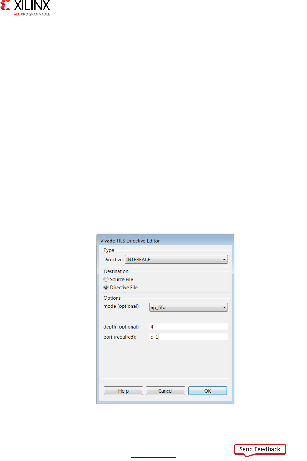
High-Level Synthesis 360
UG902 (v2017.1) April 5, 2017 www.xilinx.com
Chapter 3: High-Level Synthesis Coding Styles
Multi-Access Pointers and RTL Simulation
When pointers on the interface are accessed multiple times, to read or write, Vivado HLS
cannot determine from the function interface how many reads or writes are performed.
Neither of the arguments in the function interface informs Vivado HLS how many values are
read or written.
void pointer_stream_good (volatile dout_t *d_o, volatile din_t *d_i)
Example 3-45: Volatile Pointer Interface
Unless the interface informs Vivado HLS how many values are required (for example, the
maximum size of an array), Vivado HLS assumes a single value and creates C/RTL
co-simulation for only a single input and a single output.
If the RTL ports are actually reading or writing multiple values, the RTL co-simulation stalls.
RTL co-simulation models the producer and consumer blocks that are connected to the RTL
design. If it models requires more than a single value, the RTL design stalls when trying to
read or write more than one value (because there is currently no value to read or no space
to write).
When multi-access pointers are used at the interface, Vivado HLS must be informed of the
maximum number of reads or writes on the interface. When specifying the interface, use the
depth option on the INTERFACE directive as shown in the following figure.
X-Ref Target - Figure 3-1
Figure 3-1: Vivado HLS Directive Editor with Depth Option

High-Level Synthesis 361
UG902 (v2017.1) April 5, 2017 www.xilinx.com
Chapter 3: High-Level Synthesis Coding Styles
In the above example, argument or port d_i is set to have a FIFO interface with a depth of
four. This ensures RTL co-simulation provides enough values to correctly verify the RTL.
C Builtin Functions
Vivado HLS supports the following C bultin functions:
•__builtin_clz(unsigned int x): Returns the number of leading 0-bits in x,
starting at the most significant bit position. If x is 0, the result is undefined.
•__builtin_ctz(unsigned int x): Returns the number of trailing 0-bits in x,
starting at the least significant bit position. If x is 0, the result is undefined.
The following example shows these functions may be used. This example returns the sum of
the number of leading zeros in in0 and training zeros in in1:
int foo (int in0, int in1) {
int ldz0 = __builtin_clz(in0);
int ldz1 = __builtin_ctz(in1);
return (ldz0 + ldz1);
}
Hardware Efficient C Code
When C code is compiled for a CPU, the complier transforms and optimizes the C code into
a set of CPU machine instructions. In many cases, the developers work is done at this stage.
If however, there is a need for performance the developer will seek to perform some or all
of the following:
• Understand if any additional optimizations can be performed by the compiler.
• Seek to better understand the processor architecture and modify the code to take
advantage of any architecture specific behaviors (for example, reducing conditional
branching to improve instruction pipelining)
• Modify the C code to use CPU-specific intrinsics to perform key operations in parallel.
(for example, ARM NEON intrinsics)
The same methodology applies to code written for a DSP or a GPU, and when using an
FPGA: an FPGA device is simply another target.
C code synthesized by Vivado HLS will execute on an FPGA and provide the same
functionality as the C simulation. In some cases, the developers work is done at this stage.

High-Level Synthesis 362
UG902 (v2017.1) April 5, 2017 www.xilinx.com
Chapter 3: High-Level Synthesis Coding Styles
Typically however, an FPGA is selected to implement the C code due to the superior
performance of the FPGA device - the massively parallel architecture of an FPGA allows it to
perform operations much faster than the inherently sequential operations of a processor -
and users typically wish to take advantage of that performance.
The focus here is on understanding the impact of the C code on the results which can be
achieved and how modifications to the C code can be used to extract the maximum
advantage from the first three items in this list.
Typical C Code for a Convolution Function
A standard convolution function applied to an image is used here to demonstrate how the
C code can negatively impact the performance which is possible from an FPGA. In this
example, a horizontal and then vertical convolution is performed on the data. Since the data
at edge of the image lies outside the convolution windows, the final step is to address the
data around the border.
The algorithm structure can be summarized as follows:
template<typename T, int K>
static void convolution_orig(
int width,
int height,
const T *src,
T *dst,
const T *hcoeff,
const T *vcoeff) {
T local[MAX_IMG_ROWS*MAX_IMG_COLS];
// Horizontal convolution
HconvH:for(int col = 0; col < height; col++){
HconvWfor(int row = border_width; row < width - border_width; row++){
Hconv:for(int i = - border_width; i <= border_width; i++){
}
}
// Vertical convolution
VconvH:for(int col = border_width; col < height - border_width; col++){
VconvW:for(int row = 0; row < width; row++){
Vconv:for(int i = - border_width; i <= border_width; i++){
}
}
// Border pixels
Top_Border:for(int col = 0; col < border_width; col++){
}
Side_Border:for(int col = border_width; col < height - border_width; col++){
}
Bottom_Border:for(int col = height - border_width; col < height; col++){
}
}
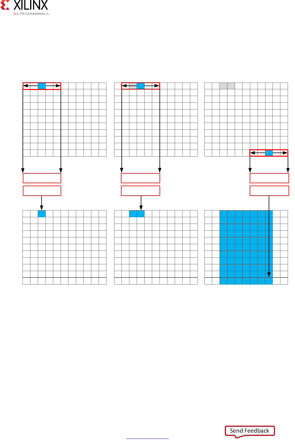
High-Level Synthesis 363
UG902 (v2017.1) April 5, 2017 www.xilinx.com
Chapter 3: High-Level Synthesis Coding Styles
Horizontal Convolution
The first step in this is to perform the convolution in the horizontal direction as shown in
the following figure.
The convolution is performed using K samples of data and K convolution coefficients. In the
figure above, K is shown as 5 however the value of K is defined in the code. To perform the
convolution, a minimum of K data samples are required. The convolution window cannot
start at the first pixel, since the window would need to include pixels which are outside the
image.
By performing a symmetric convolution, the first K data samples from input src can be
convolved with the horizontal coefficients and the first output calculated. To calculate the
second output, the next set of K data samples are used. This calculation proceeds along
each row until the final output is written.
X-Ref Target - Figure 3-2
Figure 3-2: Horizontal Convolution
)LUVW2XWSXW 6HFRQG2XWSXW )LQDO2XWSXW
VUF
+VDPS
ORFDO
+FRHII
+VDPS
+FRHII
+VDPS
+FRHII
;

High-Level Synthesis 364
UG902 (v2017.1) April 5, 2017 www.xilinx.com
Chapter 3: High-Level Synthesis Coding Styles
The final result is a smaller image, shown above in blue. The pixels along the vertical border
are addressed later.
The C code for performing this operation is shown below.
const int conv_size = K;
const int border_width = int(conv_size / 2);
#ifndef __SYNTHESIS__
T * const local = new T[MAX_IMG_ROWS*MAX_IMG_COLS];
#else // Static storage allocation for HLS, dynamic otherwise
T local[MAX_IMG_ROWS*MAX_IMG_COLS];
#endif
Clear_Local:for(int i = 0; i < height * width; i++){
local[i]=0;
}
// Horizontal convolution
HconvH:for(int col = 0; col < height; col++){
HconvWfor(int row = border_width; row < width - border_width; row++){
int pixel = col * width + row;
Hconv:for(int i = - border_width; i <= border_width; i++){
local[pixel] += src[pixel + i] * hcoeff[i + border_width];
}
}
}
Note: Only use the __SYNTHESIS__ macro in the code to be synthesized. Do not use this macro in the
test bench, because it is not obeyed by C simulation or C RTL co-simulation.
The code is straight forward and intuitive. There are already however some issues with this
C code and three which will negatively impact the quality of the hardware results.
The first issue is the requirement for two separate storage requirements. The results are
stored in an internal local array. This requires an array of HEIGHT*WIDTH which for a
standard video image of 1920*1080 will hold 2,073,600 vales. On some Windows systems, it
is not uncommon for this amount of local storage to create issues. The data for a local array
is placed on the stack and not the heap which is managed by the OS.
A useful way to avoid such issues is to use the __SYNTHESIS__ macro. This macro is
automatically defined when synthesis is executed. The code shown above will use the
dynamic memory allocation during C simulation to avoid any compilation issues and only
use the static storage during synthesis. A downside of using this macro is the code verified
by C simulation is not the same code which is synthesized. In this case however, the code is
not complex and the behavior will be the same.

High-Level Synthesis 365
UG902 (v2017.1) April 5, 2017 www.xilinx.com
Chapter 3: High-Level Synthesis Coding Styles
The first issue for the quality of the FPGA implementation is the array local. Since this is
an array it will be implemented using internal FPGA block RAM. This is a very large memory
to implement inside the FPGA. It may require a larger and more costly FPGA device. The use
of block RAM can be minimized by using the DATAFLOW optimization and streaming the
data through small efficient FIFOs, but this will require the data to be used in a streaming
manner.
The next issue is the initialization for array local. The loop Clear_Local is used to set
the values in array local to zero. Even if this loop is pipelined, this operation will require
approximately 2 million clock cycles (HEIGHT*WIDTH) to implement. This same initialization
of the data could be performed using a temporary variable inside loop HConv to initialize
the accumulation before the write.
Finally, the throughput of the data is limited by the data access pattern.
• For the first output, the first K values are read from the input.
• To calculate the second output, the same K-1 values are re-read through the data input
port.
• This process of re-reading the data is repeated for the entire image.
One of the keys to a high-performance FPGA is to minimize the access to and from the
top-level function arguments. The top-level function arguments become the data ports on
the RTL block. With the code shown above, the data cannot be streamed directly from a
processor using a DMA operation, since the data is required to be re-read time and again.
Re-reading inputs also limits the rate at which the FPGA can process samples.
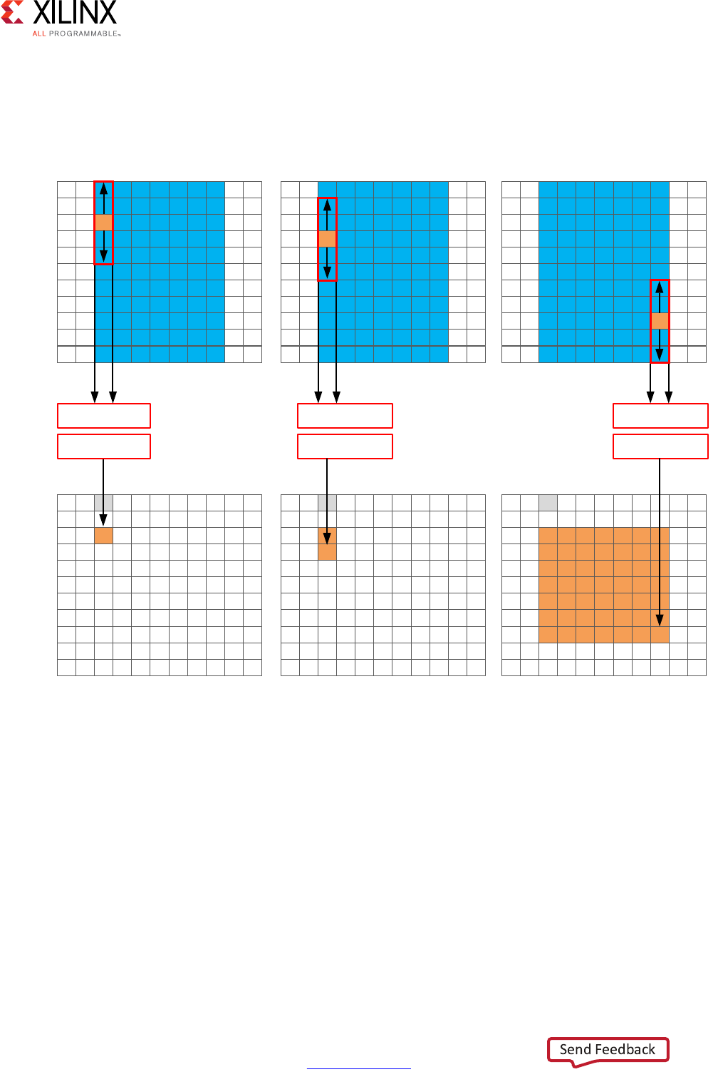
High-Level Synthesis 366
UG902 (v2017.1) April 5, 2017 www.xilinx.com
Chapter 3: High-Level Synthesis Coding Styles
Vertical Convolution
The next step is to perform the vertical convolution shown in the following figure.
The process for the vertical convolution is similar to the horizontal convolution. A set of K
data samples is required to convolve with the convolution coefficients, Vcoeff in this case.
After the first output is created using the first K samples in the vertical direction, the next
set K values are used to create the second output. The process continues down through
each column until the final output is created.
After the vertical convolution, the image is now smaller then the source image src due to
both the horizontal and vertical border effect.
X-Ref Target - Figure 3-3
Figure 3-3: Vertical Convolution
)LUVW2XWSXW 6HFRQG2XWSXW )LQDO2XWSXW
ORFDO
9VDPS
GVW
9FRHII
9VDPS
9FRHII
9VDPS
9FRQY
;

High-Level Synthesis 367
UG902 (v2017.1) April 5, 2017 www.xilinx.com
Chapter 3: High-Level Synthesis Coding Styles
The code for performing these operations is:
Clear_Dst:for(int i = 0; i < height * width; i++){
dst[i]=0;
}
// Vertical convolution
VconvH:for(int col = border_width; col < height - border_width; col++){
VconvW:for(int row = 0; row < width; row++){
int pixel = col * width + row;
Vconv:for(int i = - border_width; i <= border_width; i++){
int offset = i * width;
dst[pixel] += local[pixel + offset] * vcoeff[i + border_width];
}
}
}
This code highlights similar issues to those already discussed with the horizontal
convolution code.
• Many clock cycles are spent to set the values in the output image dst to zero. In this
case, approximately another 2 million cycles for a 1920*1080 image size.
• There are multiple accesses per pixel to re-read data stored in array local.
• There are multiple writes per pixel to the output array/port dst.
Another issue with the code above is the access pattern into array local. The algorithm
requires the data on row K to be available to perform the first calculation. Processing data
down the rows before proceeding to the next column requires the entire image to be stored
locally. In addition, because the data is not streamed out of array local, a FIFO cannot be
used to implement the memory channels created by DATAFLOW optimization. If DATAFLOW
optimization is used on this design, this memory channel requires a ping-pong buffer: this
doubles the memory requirements for the implementation to approximately 4 million data
samples all stored locally on the FPGA.
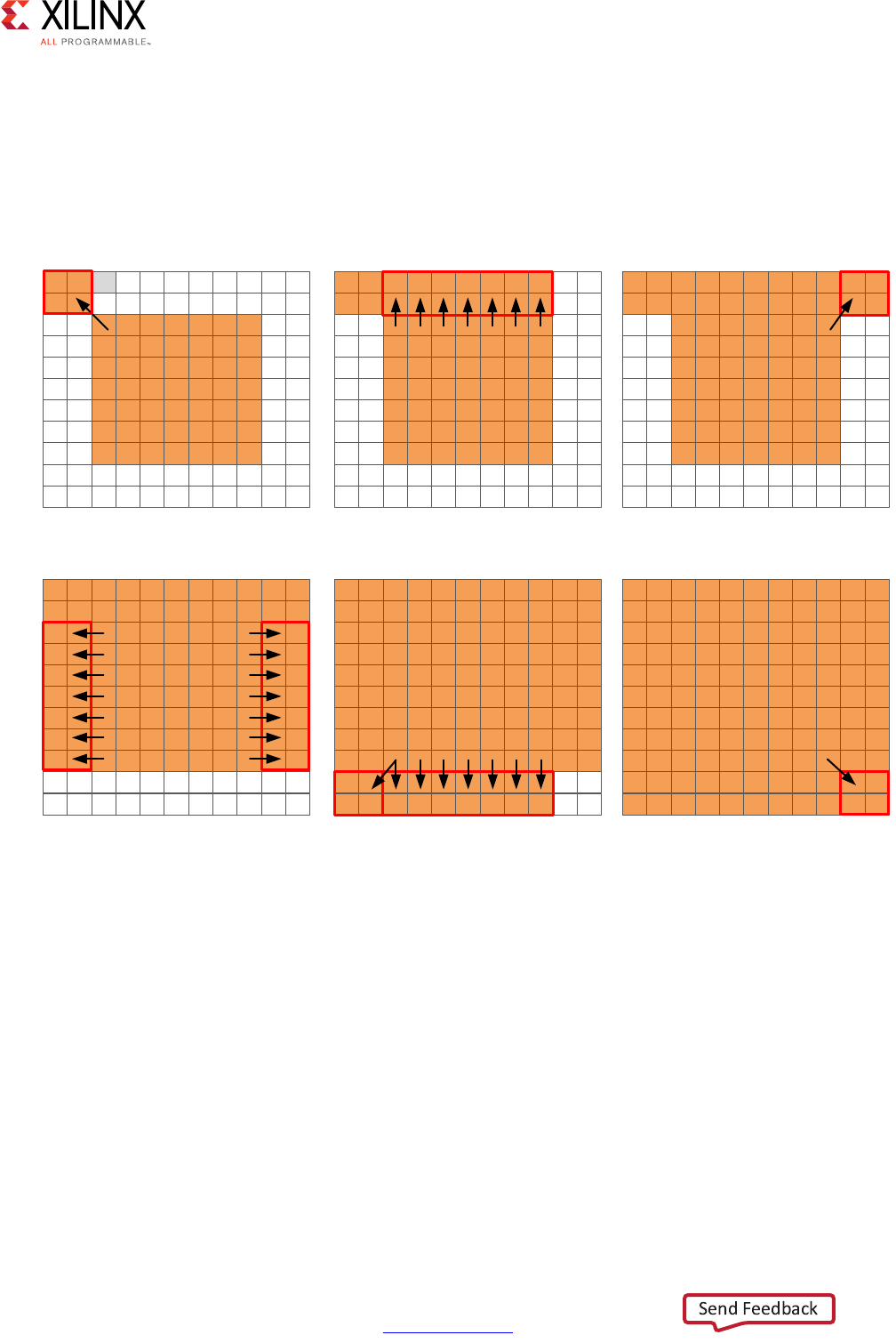
High-Level Synthesis 368
UG902 (v2017.1) April 5, 2017 www.xilinx.com
Chapter 3: High-Level Synthesis Coding Styles
Border Pixels
The final step in performing the convolution is to create the data around the border. These
pixels can be created by simply re-using the nearest pixel in the convolved output. The
following figures shows how this is achieved.
X-Ref Target - Figure 3-4
Figure 3-4: Convolution Border Samples
7RS/HIW 7RS5RZ 7RS5LJKW
/HIWDQG5LJKW(GJHV %RWWRP/HIWDQG%RWWRP5RZ %RWWRP5LJKW
GVW
GVW
;

High-Level Synthesis 369
UG902 (v2017.1) April 5, 2017 www.xilinx.com
Chapter 3: High-Level Synthesis Coding Styles
The border region is populated with the nearest valid value. The following code performs
the operations shown in the figure.
int border_width_offset = border_width * width;
int border_height_offset = (height - border_width - 1) * width;
// Border pixels
Top_Border:for(int col = 0; col < border_width; col++){
int offset = col * width;
for(int row = 0; row < border_width; row++){
int pixel = offset + row;
dst[pixel] = dst[border_width_offset + border_width];
}
for(int row = border_width; row < width - border_width; row++){
int pixel = offset + row;
dst[pixel] = dst[border_width_offset + row];
}
for(int row = width - border_width; row < width; row++){
int pixel = offset + row;
dst[pixel] = dst[border_width_offset + width - border_width - 1];
}
}
Side_Border:for(int col = border_width; col < height - border_width; col++){
int offset = col * width;
for(int row = 0; row < border_width; row++){
int pixel = offset + row;
dst[pixel] = dst[offset + border_width];
}
for(int row = width - border_width; row < width; row++){
int pixel = offset + row;
dst[pixel] = dst[offset + width - border_width - 1];
}
}
Bottom_Border:for(int col = height - border_width; col < height; col++){
int offset = col * width;
for(int row = 0; row < border_width; row++){
int pixel = offset + row;
dst[pixel] = dst[border_height_offset + border_width];
}
for(int row = border_width; row < width - border_width; row++){
int pixel = offset + row;
dst[pixel] = dst[border_height_offset + row];
}
for(int row = width - border_width; row < width; row++){
int pixel = offset + row;
dst[pixel] = dst[border_height_offset + width - border_width - 1];
}
}
The code suffers from the same repeated access for data. The data stored outside the FPGA
in array dst must now be available to be read as input data re-read multiple time. Even in
the first loop, dst[border_width_offset + border_width] is read multiple times but the
values of border_width_offset and border_width do not change.

High-Level Synthesis 370
UG902 (v2017.1) April 5, 2017 www.xilinx.com
Chapter 3: High-Level Synthesis Coding Styles
The final aspect where this coding style negatively impact the performance and quality of
the FPGA implementation is the structure of how the different conditions is address. A
for-loop processes the operations for each condition: top-left, top-row, etc. The
optimization choice here is to:
Pipelining the top-level loops, (Top_Border, Side_Border, Bottom_Border) is not
possible in this case because some of the sub-loops have variable bounds (based on the
value of input width). In this case you must pipeline the sub-loops and execute each set of
pipelined loops serially.
The question of whether to pipeline the top-level loop and unroll the sub-loops or pipeline
the sub-loops individually is determined by the loop limits and how many resources are
available on the FPGA device. If the top-level loop limit is small, unroll the loops to replicate
the hardware and meet performance. If the top-level loop limit is large, pipeline the lower
level loops and lose some performance by executing them sequentially in a loop
(Top_Border, Side_Border, Bottom_Border).
As shown in this review of a standard convolution algorithm, the following coding styles
negatively impact the performance and size of the FPGA implementation:
• Setting default values in arrays costs clock cycles and performance.
• Multiple accesses to read and then re-read data costs clock cycles and performance.
• Accessing data in an arbitrary or random access manner requires the data to be stored
locally in arrays and costs resources.
Ensuring the Continuous Flow of Data and Data Reuse
The key to implementing the convolution example reviewed in the previous section as a
high-performance design with minimal resources is to consider how the FPGA
implementation will be used in the overall system. The ideal behavior is to have the data
samples constantly flow through the FPGA.
• Maximize the flow of data through the system. Refrain from using any coding
techniques or algorithm behavior which limits the flow of data.
• Maximize the reuse of data. Use local caches to ensure there are no requirements to
re-read data and the incoming data can keep flowing.
The first step is to ensure you perform optimal I/O operations into and out of the FPGA. The
convolution algorithm is performed on an image. When data from an image is produced
and consumed, it is transferred in a standard raster-scan manner as shown in the following
figure.
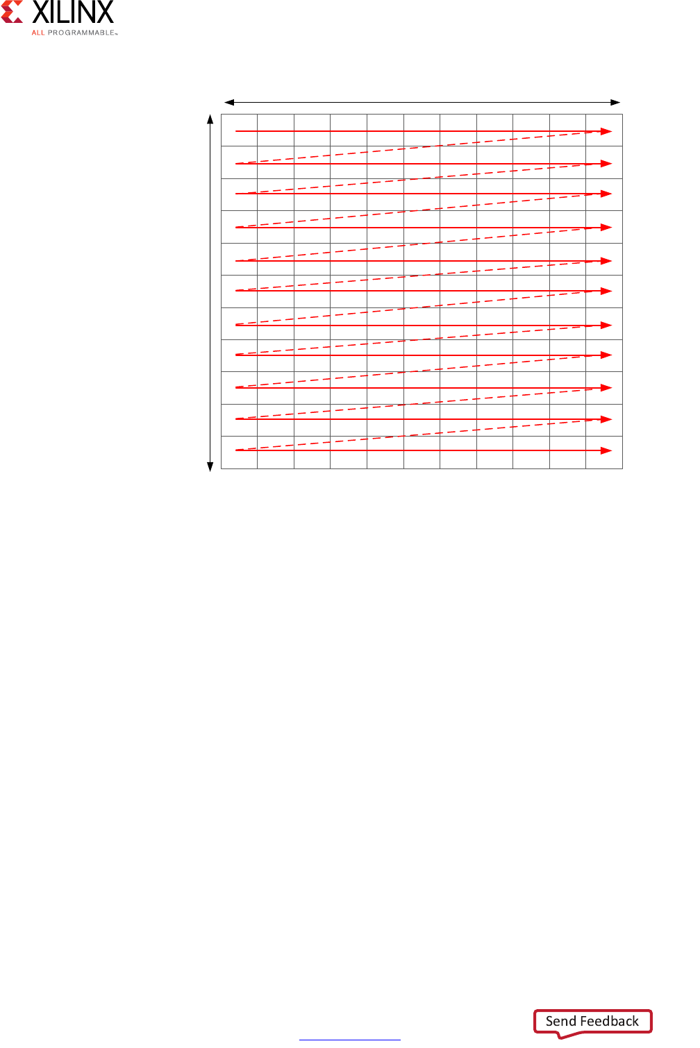
High-Level Synthesis 371
UG902 (v2017.1) April 5, 2017 www.xilinx.com
Chapter 3: High-Level Synthesis Coding Styles
If the data is transferred from the CPU or system memory to the FPGA it will typically be
transferred in this streaming manner. The data transferred from the FPGA back to the
system should also be performed in this manner.
Using HLS Streams for Streaming Data
One of the first enhancements which can be made to the earlier code is to use the HLS
stream construct, typically referred to as an hls::stream. An hls::stream object can be used to
store data samples in the same manner as an array. The data in an hls::stream can only be
accessed sequentially. In the C code, the hls::stream behaves like a FIFO of infinite depth.
Code written using hls::streams will generally create designs in an FPGA which have
high-performance and use few resources because an hls::stream enforces a coding style
which is ideal for implementation in an FPGA.
Multiple reads of the same data from an hls::stream are impossible. Once the data has been
read from an hls::stream it no longer exists in the stream. This helps remove this coding
practice.
If the data from an hls::stream is required again, it must be cached. This is another good
practice when writing code to be synthesized on an FPGA.
X-Ref Target - Figure 3-5
Figure 3-5: Raster Scan Order
:LGWK
+HLJKW
;

High-Level Synthesis 372
UG902 (v2017.1) April 5, 2017 www.xilinx.com
Chapter 3: High-Level Synthesis Coding Styles
The hls::stream forces the C code to be developed in a manner which ideal for an FPGA
implementation.
When an hls::stream is synthesized it is automatically implemented as a FIFO channel which
is 1 element deep. This is the ideal hardware for connecting pipelined tasks.
There is no requirement to use hls::streams and the same implementation can be performed
using arrays in the C code. The hls::stream construct does help enforce good coding
practices. More details on hls::streams are provided in HLS Stream Library in Chapter 2.
With an hls::stream construct the outline of the new optimized code is as follows:
template<typename T, int K>
static void convolution_strm(
int width,
int height,
hls::stream<T> &src,
hls::stream<T> &dst,
const T *hcoeff,
const T *vcoeff)
{
hls::stream<T> hconv("hconv");
hls::stream<T> vconv("vconv");
// These assertions let HLS know the upper bounds of loops
assert(height < MAX_IMG_ROWS);
assert(width < MAX_IMG_COLS);
assert(vconv_xlim < MAX_IMG_COLS - (K - 1));
// Horizontal convolution
HConvH:for(int col = 0; col < height; col++) {
HConvW:for(int row = 0; row < width; row++) {
HConv:for(int i = 0; i < K; i++) {
}
}
}
// Vertical convolution
VConvH:for(int col = 0; col < height; col++) {
VConvW:for(int row = 0; row < vconv_xlim; row++) {
VConv:for(int i = 0; i < K; i++) {
}
}
Border:for (int i = 0; i < height; i++) {
for (int j = 0; j < width; j++) {
}
}
Some noticeable differences compared to the earlier code are:
• The input and output data is now modelled as hls::streams.
• Instead of a single local array of size HEIGHT*WDITH there are two internal hls::streams
used to save the output of the horizontal and vertical convolutions.
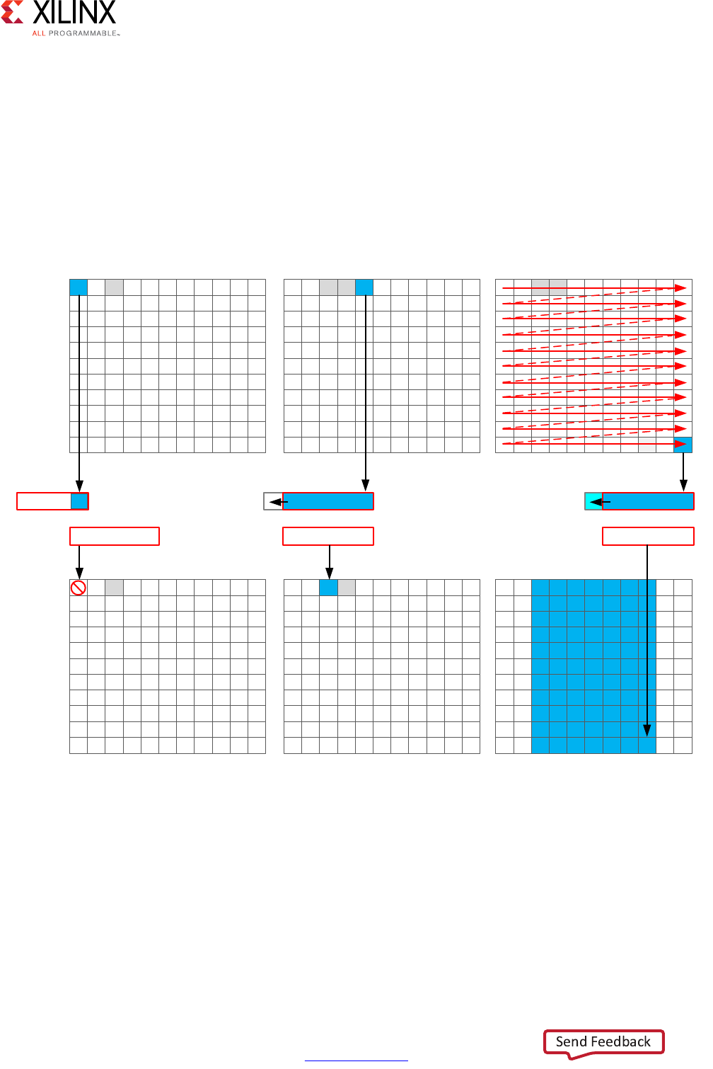
High-Level Synthesis 373
UG902 (v2017.1) April 5, 2017 www.xilinx.com
Chapter 3: High-Level Synthesis Coding Styles
In addition, some assert statements are used to specify the maximize of loop bounds. This
is a good coding style which allows HLS to automatically report on the latencies of variable
bounded loops and optimize the loop bounds.
Horizontal Convolution
To perform the calculation in a more efficient manner for FPGA implementation, the
horizontal convolution is computed as shown in the following figure.
Using an hls::stream enforces the good algorithm practice of forcing you to start by reading
the first sample first, as opposed to performing a random access into data. The algorithm
must use the K previous samples to compute the convolution result, it therefore copies the
sample into a temporary cache hwin. For the first calculation there are not enough values
in hwin to compute a result, so no output values are written.
X-Ref Target - Figure 3-6
Figure 3-6: Streaming Horizontal Convolution
)LUVW&DOFXODWLRQ )LUVW2XWSXW )LQDO2XWSXW
VUF
+ZLQ
KFRQY
+FRQY
+VDPS
+FRQY
+VDPS
+FRQY
;

High-Level Synthesis 374
UG902 (v2017.1) April 5, 2017 www.xilinx.com
Chapter 3: High-Level Synthesis Coding Styles
The algorithm keeps reading input samples a caching them into hwin. Each time is reads a
new sample, it pushes an unneeded sample out of hwin. The first time an output value can
be written is after the Kth input has been read. Now an output value can be written.
The algorithm proceeds in this manner along the rows until the final sample has been read.
At point, only the last K samples are stored in hwin: all that is required to compute the
convolution.
The code to perform these operations is shown below.
// Horizontal convolution
HConvW:for(int row = 0; row < width; row++) {
HconvW:for(int row = border_width; row < width - border_width; row++){
T in_val = src.read();
T out_val = 0;
HConv:for(int i = 0; i < K; i++) {
hwin[i] = i < K - 1 ? hwin[i + 1] : in_val;
out_val += hwin[i] * hcoeff[i];
}
if (row >= K - 1)
hconv << out_val;
}
}
An interesting point to note in the code above is use of the temporary variable out_val to
perform the convolution calculation. This variable is set to zero before the calculation is
performed, negating the need to spend 2 million clocks cycle to reset the values, as in the
pervious example.
Throughout the entire process, the samples in the src input are processed in a
raster-streaming manner. Every sample is read in turn. The outputs from the task are either
discarded or used, but the task keeps constantly computing. This represents a difference
from code written to perform on a CPU.
In a CPU architecture, conditional or branch operations are often avoided. When the
program needs to branch it loses any instructions stored in the CPU fetch pipeline. In an
FPGA architecture, a separate path already exists in the hardware for each conditional
branch and there is no performance penalty associated with branching inside a pipelined
task. It is simply a case of selecting which branch to use.
The outputs are stored in the hls::stream hconv for use by the vertical convolution loop.
Vertical Convolution
The vertical convolution represents a challenge to the streaming data model preferred by
an FPGA. The data must be accessed by column but you do not wish to store the entire
image. The solution is to use line buffers, as shown in the following figure.
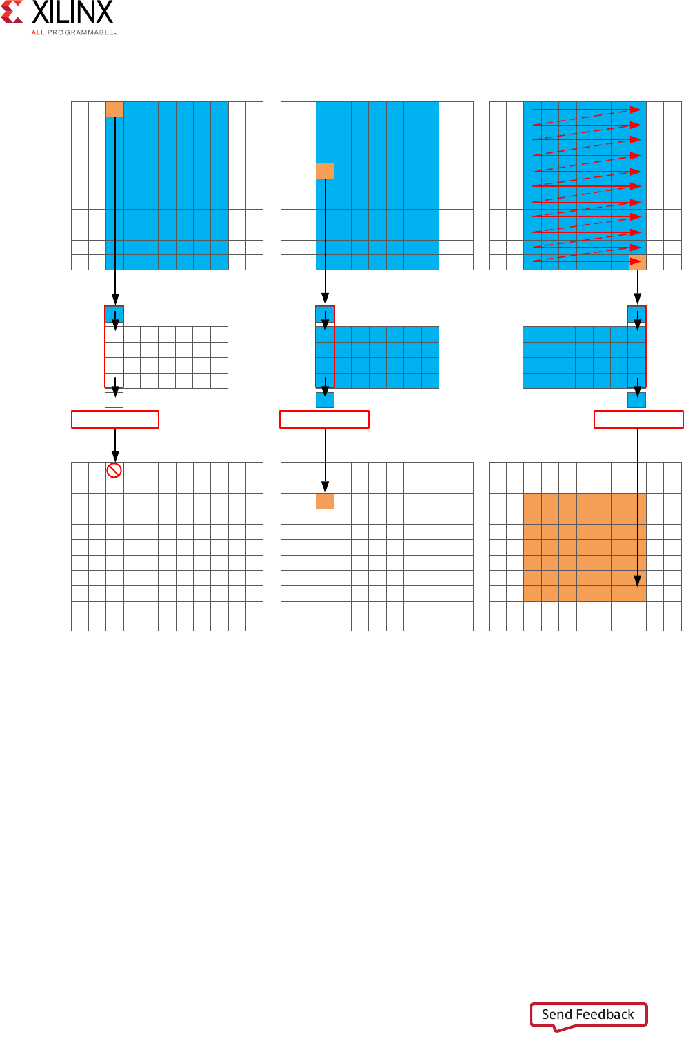
High-Level Synthesis 375
UG902 (v2017.1) April 5, 2017 www.xilinx.com
Chapter 3: High-Level Synthesis Coding Styles
Once again, the samples are read in a streaming manner, this time from the hls::stream
hconv. The algorithm requires at least K-1 lines of data before it can process the first
sample. All the calculations performed before this are discarded.
A line buffer allows K-1 lines of data to be stored. Each time a new sample is read, another
sample is pushed out the line buffer. An interesting point to note here is that the newest
sample is used in the calculation and then the sample is stored into the line buffer and the
old sample ejected out. This ensure only K-1 lines are required to be cached, rather than K
lines. Although a line buffer does require multiple lines to be stored locally, the convolution
kernel size K is always much less than the 1080 lines in a full video image.
X-Ref Target - Figure 3-7
Figure 3-7: Streaming Vertical Convolution
)LUVW&DOFXODWLRQ )LUVW2XWSXW )LQDO2XWSXW
KFRQY
YFRQY
9FRQY 9FRQY 9FRQY
;

High-Level Synthesis 376
UG902 (v2017.1) April 5, 2017 www.xilinx.com
Chapter 3: High-Level Synthesis Coding Styles
The first calculation can be performed when the first sample on the Kth line is read. The
algorithm then proceeds to output values until the final pixel is read.
// Vertical convolution
VConvH:for(int col = 0; col < height; col++) {
VConvW:for(int row = 0; row < vconv_xlim; row++) {
#pragma HLS DEPENDENCE variable=linebuf inter false
#pragma HLS PIPELINE
T in_val = hconv.read();
T out_val = 0;
VConv:for(int i = 0; i < K; i++) {
T vwin_val = i < K - 1 ? linebuf[i][row] : in_val;
out_val += vwin_val * vcoeff[i];
if (i > 0)
linebuf[i - 1][row] = vwin_val;
}
if (col >= K - 1)
vconv << out_val;
}
}
The code above once again process all the samples in the design in a streaming manner.
The task is constantly running. The use of the hls::stream construct forces you to cache the
data locally. This is an ideal strategy when targeting an FPGA.
Border Pixels
The final step in the algorithm is to replicate the edge pixels into the border region. Once
again, to ensure the constant flow or data and data reuse the algorithm makes use of an
hls::stream and caching.
The following figure shows how the border samples are aligned into the image.
• Each sample is read from the vconv output from the vertical convolution.
• The sample is then cached as one of 4 possible pixel types.
• The sample is then written to the output stream.
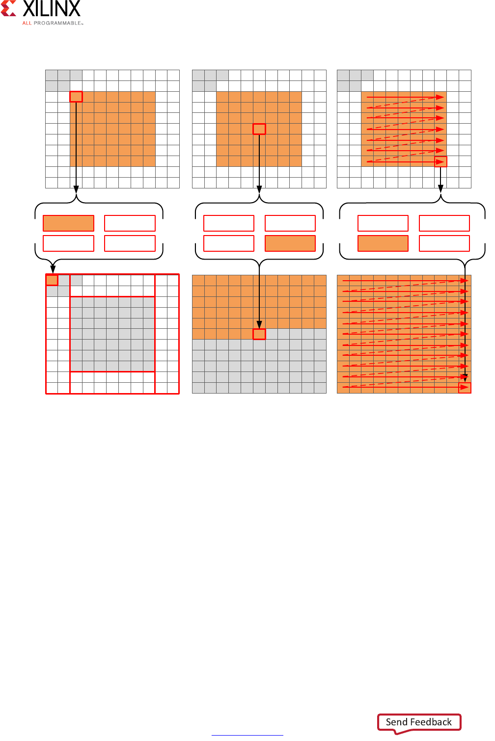
High-Level Synthesis 377
UG902 (v2017.1) April 5, 2017 www.xilinx.com
Chapter 3: High-Level Synthesis Coding Styles
X-Ref Target - Figure 3-8
Figure 3-8: Streaming Border Samples
)LUVW2XWSXW 0LGGOH2XWSXW )LQDO2XWSXW
YFRQY
/HIW(GJH %RUGHU
GVW
5LJKW(GJH 5DZ3L[HO
/HIW(GJH %RUGHU
5LJKW(GJH 5DZ3L[HO
/HIW(GJH %RUGHU
5LJKW(GJH 5DZ3L[HO
%RUGHU
5DZ3L[HO
%RUGHU
5LJKW(GJH
/HIW(GJH
;

High-Level Synthesis 378
UG902 (v2017.1) April 5, 2017 www.xilinx.com
Chapter 3: High-Level Synthesis Coding Styles
The code for determining the location of the border pixels is:
Border:for (int i = 0; i < height; i++) {
for (int j = 0; j < width; j++) {
T pix_in, l_edge_pix, r_edge_pix, pix_out;
#pragma HLS PIPELINE
if (i == 0 || (i > border_width && i < height - border_width)) {
if (j < width - (K - 1)) {
pix_in = vconv.read();
borderbuf[j] = pix_in;
}
if (j == 0) {
l_edge_pix = pix_in;
}
if (j == width - K) {
r_edge_pix = pix_in;
}
}
if (j <= border_width) {
pix_out = l_edge_pix;
} else if (j >= width - border_width - 1) {
pix_out = r_edge_pix;
} else {
pix_out = borderbuf[j - border_width];
}
dst << pix_out;
}
}
}
A notable difference with this new code is the extensive use of conditionals inside the tasks.
This allows the task, once it is pipelined, to continuously process data and the result of the
conditionals does not impact the execution of the pipeline: the result will impact the output
values but the pipeline with keep processing so long as input samples are available.

High-Level Synthesis 379
UG902 (v2017.1) April 5, 2017 www.xilinx.com
Chapter 3: High-Level Synthesis Coding Styles
The final code for this FPGA-friendly algorithm has the following optimization directives
used.
template<typename T, int K>
static void convolution_strm(
int width,
int height,
hls::stream<T> &src,
hls::stream<T> &dst,
const T *hcoeff,
const T *vcoeff)
{
#pragma HLS DATAFLOW
#pragma HLS ARRAY_PARTITION variable=linebuf dim=1 complete
hls::stream<T> hconv("hconv");
hls::stream<T> vconv("vconv");
// These assertions let HLS know the upper bounds of loops
assert(height < MAX_IMG_ROWS);
assert(width < MAX_IMG_COLS);
assert(vconv_xlim < MAX_IMG_COLS - (K - 1));
// Horizontal convolution
HConvH:for(int col = 0; col < height; col++) {
HConvW:for(int row = 0; row < width; row++) {
#pragma HLS PIPELINE
HConv:for(int i = 0; i < K; i++) {
}
}
}
// Vertical convolution
VConvH:for(int col = 0; col < height; col++) {
VConvW:for(int row = 0; row < vconv_xlim; row++) {
#pragma HLS PIPELINE
#pragma HLS DEPENDENCE variable=linebuf inter false
VConv:for(int i = 0; i < K; i++) {
}
}
Border:for (int i = 0; i < height; i++) {
for (int j = 0; j < width; j++) {
#pragma HLS PIPELINE
}
}
Each of the tasks are pipelined at the sample level. The line buffer is full partitioned into
registers to ensure there are no read or write limitations due to insufficient block RAM
ports. The line buffer also requires a dependence directive. All of the tasks execute in a
dataflow region which will ensure the tasks run concurrently. The hls::streams are
automatically implemented as FIFOs with 1 element.

High-Level Synthesis 380
UG902 (v2017.1) April 5, 2017 www.xilinx.com
Chapter 3: High-Level Synthesis Coding Styles
Summary of C for Efficient Hardware
Minimize data input reads. Once data has been read into the block it can easily feed many
parallel paths but the input ports can be bottlenecks to performance. Read data once and
use a local cache if the data must be reused.
Minimize accesses to arrays, especially large arrays. Arrays are implemented in block RAM
which like I/O ports only have a limited number of ports and can be bottlenecks to
performance. Arrays can be partitioned into smaller arrays and even individual registers but
partitioning large arrays will result in many registers being used. Use small localized caches
to hold results such as accumulations and then write the final result to the array.
Seek to perform conditional branching inside pipelined tasks rather than conditionally
execute tasks, even pipelined tasks. Conditionals will be implemented as separate paths in
the pipeline. Allowing the data from one task to flow into with the conditional performed
inside the next task will result in a higher performing system.
Minimize output writes for the same reason as input reads: ports are bottlenecks.
Replicating addition ports simply pushes the issue further out into the system.
For C code which processes data in a streaming manner, consider using hls::streams as
these will enforce good coding practices. It is much more productive to design an algorithm
in C which will result in a high-performance FPGA implementation than debug why the
FPGA is not operating at the performance required.
C++ Classes and Templates
C++ classes are fully supported for synthesis with Vivado HLS. The top-level for synthesis
must be a function. A class cannot be the top-level for synthesis. To synthesize a class
member function, instantiate the class itself into function. Do not simply instantiate the
top-level class into the test bench. The following code example shows how class CFir
(defined in the header file discussed next) is instantiated in the top-level function cpp_FIR
and used to implement an FIR filter.
#include "cpp_FIR.h"
// Top-level function with class instantiated
data_t cpp_FIR(data_t x)
{
static CFir<coef_t, data_t, acc_t> fir1;
cout << fir1;
return fir1(x);
}
Example 3-46: C++ FIR Filter

High-Level Synthesis 381
UG902 (v2017.1) April 5, 2017 www.xilinx.com
Chapter 3: High-Level Synthesis Coding Styles
IMPORTANT: Classes and class member functions cannot be the top-level for synthesis. Instantiate the
class in a top-level function.
Before examining the class used to implement the design in Example 3-46, it is worth
noting Vivado HLS ignores the standard output stream cout during synthesis. When
synthesized, Vivado HLS issues the following warnings:
INFO [SYNCHK-101] Discarding unsynthesizable system call:
'std::ostream::operator<<' (cpp_FIR.h:108)
INFO [SYNCHK-101] Discarding unsynthesizable system call:
'std::ostream::operator<<' (cpp_FIR.h:108)
INFO [SYNCHK-101] Discarding unsynthesizable system call: 'std::operator<<
<std::char_traits<char> >' (cpp_FIR.h:110)
The following code example shows the header file cpp_FIR.h, including the definition of
class CFir and its associated member functions. In this example the operator member
functions () and << are overloaded operators, which are respectively used to execute the
main algorithm and used with cout to format the data for display during C simulation.
#include <fstream>
#include <iostream>
#include <iomanip>
#include <cstdlib>
using namespace std;
#define N 85
typedef int coef_t;
typedef int data_t;
typedef int acc_t;
// Class CFir definition
template<class coef_T, class data_T, class acc_T>
class CFir {
protected:
static const coef_T c[N];
data_T shift_reg[N-1];
private:
public:
data_T operator()(data_T x);
template<class coef_TT, class data_TT, class acc_TT>
friend ostream&
operator<<(ostream& o, const CFir<coef_TT, data_TT, acc_TT> &f);
};
// Load FIR coefficients
template<class coef_T, class data_T, class acc_T>
const coef_T CFir<coef_T, data_T, acc_T>::c[N] = {
#include "cpp_FIR.h"
};
// FIR main algorithm
template<class coef_T, class data_T, class acc_T>
data_T CFir<coef_T, data_T, acc_T>::operator()(data_T x) {
int i;

High-Level Synthesis 382
UG902 (v2017.1) April 5, 2017 www.xilinx.com
Chapter 3: High-Level Synthesis Coding Styles
acc_t acc = 0;
data_t m;
loop: for (i = N-1; i >= 0; i--) {
if (i == 0) {
m = x;
shift_reg[0] = x;
} else {
m = shift_reg[i-1];
if (i != (N-1))
shift_reg[i] = shift_reg[i - 1];
}
acc += m * c[i];
}
return acc;
}
// Operator for displaying results
template<class coef_T, class data_T, class acc_T>
ostream& operator<<(ostream& o, const CFir<coef_T, data_T, acc_T> &f) {
for (int i = 0; i < (sizeof(f.shift_reg)/sizeof(data_T)); i++) {
o << shift_reg[ << i << ]= << f.shift_reg[i] << endl;
}
o << ______________ << endl;
return o;
}
data_t cpp_FIR(data_t x);
Example 3-47: C++ Header File Defining Classes
The test bench Example 3-46 is shown in the following code example and demonstrates
how top-level function cpp_FIR is called and validated. This example highlights some of
the important attributes of a good test bench for Vivado HLS synthesis:
• The output results are checked against known good values.
• The test bench returns 0 if the results are confirmed to be correct.

High-Level Synthesis 383
UG902 (v2017.1) April 5, 2017 www.xilinx.com
Chapter 3: High-Level Synthesis Coding Styles
For more for information on test benches, see Productive Test Benches.
#include "cpp_FIR.h"
int main() {
ofstream result;
data_t output;
int retval=0;
// Open a file to saves the results
result.open(result.dat);
// Apply stimuli, call the top-level function and saves the results
for (int i = 0; i <= 250; i++)
{
output = cpp_FIR(i);
result << setw(10) << i;
result << setw(20) << output;
result << endl;
}
result.close();
// Compare the results file with the golden results
retval = system(diff --brief -w result.dat result.golden.dat);
if (retval != 0) {
printf(Test failed !!!\n);
retval=1;
} else {
printf(Test passed !\n);
}
// Return 0 if the test
return retval;
}
Example 3-48: C++ Test Bench for cpp_FIR
To apply directives to objects defined in a class:
1. Open the file where the class is defined (typically a header file).
2. Apply the directive using the Directives tab.
As with functions, all instances of a class have the same optimizations applied to them.
Constructors, Destructors, and Virtual Functions
Class constructors and destructors are included and synthesized whenever a class object is
declared.

High-Level Synthesis 384
UG902 (v2017.1) April 5, 2017 www.xilinx.com
Chapter 3: High-Level Synthesis Coding Styles
Vivado HLS supports virtual functions (including abstract functions) for synthesis, provided
that it can statically determine the function during elaboration. Vivado HLS does not
support virtual functions for synthesis in the following cases:
• Virtual functions can be defined in a multilayer inheritance class hierarchy but only
with a single inheritance.
• Dynamic polymorphism is only supported if the pointer object can be determined at
compile time. For example, such pointers cannot be used in an if-else or loop
constructs.
• An STL container cannot contain the pointer of an object and call the polymorphism
function. For example:
vector<base *> base_ptrs(10);
//Push_back some base ptrs to vector.
for (int i = 0; i < base_ptrs.size(); ++i) {
//Static elaboration cannot resolve base_ptrs[i] to actual data type.
base_ptrs[i]->virtual_function();
}
• Vivado HLS does not support cases in which the base object pointer is a global variable.
For example:
Base *base_ptr;
void func()
{
……
base_prt->virtual_function();
……
}
• The base object pointer cannot be a member variable in a class definition. For example:
// Static elaboration cannot bind base object pointer with correct data type.
class A
{
…..
Base *base_ptr;
void set_base(Base *base_ptr);
void some_func();
…..
};
void A::set_base(Base *ptr)
{
this.base_ptr = ptr;
}
void A::some_func()
{
….
base_ptr->virtual_function();
….
}

High-Level Synthesis 385
UG902 (v2017.1) April 5, 2017 www.xilinx.com
Chapter 3: High-Level Synthesis Coding Styles
• If the base object pointer or reference is in the function parameter list of constructor,
Vivado HLS does not convert it. The ISO C++ standard has depicted this in section12.7:
sometimes the behavior is undefined.
class A {
A(Base *b) {
b-> virtual _ function ();
}
};
Global Variables and Classes
Xilinx does not recommend using global variables in classes. They can prevent some
optimizations from occurring. In the following code example, a class is used to create the
component for a filter (class polyd_cell is used as a component that performs shift,
multiply and accumulate operations).
typedef long long acc_t;
typedef int mult_t;
typedef char data_t;
typedef char coef_t;
#define TAPS 3
#define PHASES 4
#define DATA_SAMPLES 256
#define CELL_SAMPLES 12
// Use k on line 73 static int k;
template <typename T0, typename T1, typename T2, typename T3, int N>
class polyd_cell {
private:
public:
T0 areg;
T0 breg;
T2 mreg;
T1 preg;
T0 shift[N];
int k; //line 73
T0 shift_output;
void exec(T1 *pcout, T0 *dataOut, T1 pcin, T3 coeff, T0 data, int col)
{
Function_label0:;
if (col==0) {
SHIFT:for (k = N-1; k >= 0; --k) {
if (k > 0)
shift[k] = shift[k-1];
else
shift[k] = data;
}
*dataOut = shift_output;
shift_output = shift[N-1];
}
*pcout = (shift[4*col]* coeff) + pcin;

High-Level Synthesis 386
UG902 (v2017.1) April 5, 2017 www.xilinx.com
Chapter 3: High-Level Synthesis Coding Styles
}
};
// Top-level function with class instantiated
void cpp_class_data (
acc_t *dataOut,
coef_t coeff1[PHASES][TAPS],
coef_t coeff2[PHASES][TAPS],
data_t dataIn[DATA_SAMPLES],
int row
) {
acc_t pcin0 = 0;
acc_t pcout0, pcout1;
data_t dout0, dout1;
int col;
static acc_t accum=0;
static int sample_count = 0;
static polyd_cell<data_t, acc_t, mult_t, coef_t, CELL_SAMPLES>
polyd_cell0;
static polyd_cell<data_t, acc_t, mult_t, coef_t, CELL_SAMPLES>
polyd_cell1;
COL:for (col = 0; col <= TAPS-1; ++col) {
polyd_cell0.exec(&pcout0,&dout0,pcin0,coeff1[row][col],dataIn[sample_count],
col);
polyd_cell1.exec(&pcout1,&dout1,pcout0,coeff2[row][col],dout0,col);
if ((row==0) && (col==2)) {
*dataOut = accum;
accum = pcout1;
} else {
accum = pcout1 + accum;
}
}
sample_count++;
}
Example 3-49: C++ Class Data Member Used for Loop Index Coding Example

High-Level Synthesis 387
UG902 (v2017.1) April 5, 2017 www.xilinx.com
Chapter 3: High-Level Synthesis Coding Styles
Within class polyd_cell there is a loop SHIFT used to shift data. If the loop index k used
in loop SHIFT was removed and replaced with the global index for k (shown earlier in the
example, but commented static int k), Vivado HLS is unable to pipeline any loop or
function in which class polyd_cell was used. Vivado HLS would issue the following
message:
@W [XFORM-503] Cannot unroll loop 'SHIFT' in function 'polyd_cell<char, long long,
int, char, 12>::exec' completely: variable loop bound.
Using local non-global variables for loop indexing ensures that Vivado HLS can perform all
optimizations.
Templates
Vivado HLS supports the use of templates in C++ for synthesis. Vivado HLS does not
support templates for the top-level function.
IMPORTANT: The top-level function cannot be a template.
In addition to the general use of templates shown in Example 3-47 and Example 3-49,
templates can be used implement a form of recursion that is not supported in standard C
synthesis (Recursive Functions).
The following code example shows a case in which a templatized struct is used to
implement a tail-recursion Fibonacci algorithm. The key to performing synthesis is that a
termination class is used to implement the final call in the recursion, where a template size
of one is used.
//Tail recursive call
template<data_t N> struct fibon_s {
template<typename T>
static T fibon_f(T a, T b) {
return fibon_s<N-1>::fibon_f(b, (a+b));
}
};
// Termination condition
template<> struct fibon_s<1> {
template<typename T>
static T fibon_f(T a, T b) {
return b;
}
};
void cpp_template(data_t a, data_t b, data_t &dout){
dout = fibon_s<FIB_N>::fibon_f(a,b);
}
Example 3-50: C++ Tail Recursion with Templates

High-Level Synthesis 388
UG902 (v2017.1) April 5, 2017 www.xilinx.com
Chapter 3: High-Level Synthesis Coding Styles
Assertions
The assert macro in C is supported for synthesis when used to assert range information. For
example, the upper limit of variables and loop-bounds.
As noted in Variable Loop Bounds, when variable loop bounds are present, Vivado HLS
cannot determine the latency for all iterations of the loop and reports the latency with a
question mark. The Tripcount directive can inform Vivado HLS of the loop bounds, but this
information is only used for reporting purposes and does not impact the result of synthesis
(the same sized hardware is created, with or without the Tripcount directive).
The following code example shows how assertions can inform Vivado HLS about the
maximum range of variables, and how those assertions are used to produce more optimal
hardware.
Before using assertions, the header file that defines the assert macro must be included. In
this example, this is included in the header file.
#ifndef _loop_sequential_assert_H_
#define _loop_sequential_assert_H_
#include <stdio.h>
#include <assert.h>
#include ap_cint.h
#define N 32
typedef int8 din_t;
typedef int13 dout_t;
typedef uint8 dsel_t;
void loop_sequential_assert(din_t A[N], din_t B[N], dout_t X[N], dout_t Y[N], dsel_t
xlimit, dsel_t ylimit);
#endif
Example 3-51: Variable Loop Bounds Rewritten
In the main code two assert statements are placed before each of the loops.
assert(xlimit<32);
...
assert(ylimit<16);
...

High-Level Synthesis 389
UG902 (v2017.1) April 5, 2017 www.xilinx.com
Chapter 3: High-Level Synthesis Coding Styles
These assertions:
• Guarantee that if the assertion is false and the value is greater than that stated, the C
simulation will fail. This also highlights why it is important to simulate the C code
before synthesis: confirm the design is valid before synthesis.
• Inform Vivado HLS that the range of this variable will not exceed this value and this fact
can optimize the variables size in the RTL and in this case, the loop iteration count.
The following code example shows these assertions.
#include "loop_sequential_assert.h"
void loop_sequential_assert(din_t A[N], din_t B[N], dout_t X[N], dout_t Y[N], dsel_t
xlimit, dsel_t ylimit) {
dout_t X_accum=0;
dout_t Y_accum=0;
int i,j;
assert(xlimit<32);
SUM_X:for (i=0;i<=xlimit; i++) {
X_accum += A[i];
X[i] = X_accum;
}
assert(ylimit<16);
SUM_Y:for (i=0;i<=ylimit; i++) {
Y_accum += B[i];
Y[i] = Y_accum;
}
}
Example 3-52: Variable Loop Bounds Rewritten
Except for the assert macros, this code is the same as that shown in Example 3-13. There are
two important differences in the synthesis report after synthesis.
Without the assert macros, the report is as follows, showing that the loop tripcount can vary
from 1 to 256 because the variables for the loop-bounds are of data type d_sel that is an
8-bit variable.
* Loop Latency:
+----------+-----------+----------+
|Target II |Trip Count |Pipelined |
+----------+-----------+----------+
|- SUM_X |1 ~ 256 |no |
|- SUM_Y |1 ~ 256 |no |
+----------+-----------+----------+

High-Level Synthesis 390
UG902 (v2017.1) April 5, 2017 www.xilinx.com
Chapter 3: High-Level Synthesis Coding Styles
In the version with the assert macros, the report shows the loops SUM_X and SUM_Y
reported Tripcount of 32 and 16. Because the assertions assert that the values will never be
greater than 32 and 16, Vivado HLS can use this in the reporting.
* Loop Latency:
+----------+-----------+----------+
|Target II |Trip Count |Pipelined |
+----------+-----------+----------+
|- SUM_X |1 ~ 32 |no |
|- SUM_Y |1 ~ 16 |no |
+----------+-----------+----------+
In addition, and unlike using the Tripcount directive, the assert statements can provide
more optimal hardware. In the case without assertions, the final hardware uses variables
and counters that are sized for a maximum of 256 loop iterations.
* Expression:
+----------+------------------------+-------+---+----+
|Operation |Variable Name |DSP48E |FF |LUT |
+----------+------------------------+-------+---+----+
|+ |X_accum_1_fu_182_p2 |0 |0 |13 |
|+ |Y_accum_1_fu_209_p2 |0 |0 |13 |
|+ |indvar_next6_fu_158_p2 |0 |0 |9 |
|+ |indvar_next_fu_194_p2 |0 |0 |9 |
|+ |tmp1_fu_172_p2 |0 |0 |9 |
|+ |tmp_fu_147_p2 |0 |0 |9 |
|icmp |exitcond1_fu_189_p2 |0 |0 |9 |
|icmp |exitcond_fu_153_p2 |0 |0 |9 |
+----------+------------------------+-------+---+----+
|Total | |0 |0 |80 |
+----------+------------------------+-------+---+----+
The code which asserts the variable ranges are smaller than the maximum possible range
results in a smaller RTL design.
* Expression:
+----------+------------------------+-------+---+----+
|Operation |Variable Name |DSP48E |FF |LUT |
+----------+------------------------+-------+---+----+
|+ |X_accum_1_fu_176_p2 |0 |0 |13 |
|+ |Y_accum_1_fu_207_p2 |0 |0 |13 |
|+ |i_2_fu_158_p2 |0 |0 |6 |
|+ |i_3_fu_192_p2 |0 |0 |5 |
|icmp |tmp_2_fu_153_p2 |0 |0 |7 |
|icmp |tmp_9_fu_187_p2 |0 |0 |6 |
+----------+------------------------+-------+---+----+
|Total | |0 |0 |50 |
+----------+------------------------+-------+---+----+
Assertions can indicate the range of any variable in the design. It is important to execute a
C simulation that covers all possible cases when using assertions. This will confirm that the
assertions that Vivado HLS uses are valid.

High-Level Synthesis 391
UG902 (v2017.1) April 5, 2017 www.xilinx.com
Chapter 3: High-Level Synthesis Coding Styles
SystemC Synthesis
Vivado HLS supports SystemC (IEEE standard 1666), a C++ class library used to model
hardware. The library is available at the Accellera website (www.accellera.org). For synthesis,
Vivado HLS supports the SystemC Synthesizable Subset (Draft 1.3) for SystemC version 2.1.
This section provides information on the synthesis of SystemC functions with Vivado HLS.
This information is in addition to the information in the earlier chapters, C for Synthesis and
C++ for Synthesis. Xilinx recommends that you read those chapters to fully understand the
basic rules of coding for synthesis.
IMPORTANT: As with C and C++ designs, the top-level function for synthesis must be a function below
the top-level for C compilation sc_main(). The sc_main() function cannot be the top-level function
for synthesis.
Design Modeling
The top-level for synthesis must be an SC_MODULE. Designs can be synthesized if modeled
using the SystemC constructor processes SC_METHOD, SC_CTHREAD and the
SC_HAS_PROCESS marco or if SC_MODULES are instantiated inside other SC_MODULES.
The top-level SC_MODULE in the design cannot be a template. Templates can be used only
on submodules.
The module constructor can only define or instantiate modules. It cannot contain any
functionality.
An SC_ MODULE cannot be defined inside another SC_MODULE. (Although they can be
instantiated, as discussed later).

High-Level Synthesis 392
UG902 (v2017.1) April 5, 2017 www.xilinx.com
Chapter 3: High-Level Synthesis Coding Styles
Using SC_ MODULE
Hierarchical modules definitions are not supported. When a module is defined inside
another module (SC_ MODULE Example One), it must be converted into a version in which
the modules are not nested (SC_ MODULE Example Two).
SC_MODULE(nested1)
{
SC_MODULE(nested2)
{
sc_in<int> in0;
sc_out<int> out0;
SC_CTOR(nested2)
{
SC_METHOD(process);
sensitive<<in0;
}
void process()
{
int var =10;
out0.write(in0.read()+var);
}
};
sc_in<int> in0;
sc_out<int> out0;
nested2 nd;
SC_CTOR(nested1)
:nd(nested2)
{
nd.in0(in0);
nd.out0(out0);
}
};
Example 3-53: SC_ MODULE Example One

High-Level Synthesis 393
UG902 (v2017.1) April 5, 2017 www.xilinx.com
Chapter 3: High-Level Synthesis Coding Styles
SC_MODULE(nested2)
{
sc_in<int> in0;
sc_out<int> out0;
SC_CTOR(nested2)
{
SC_METHOD(process);
sensitive<<in0;
}
void process()
{
int var =10;
out0.write(in0.read()+var);
}
};
SC_MODULE(nested1)
{
sc_in<int> in0;
sc_out<int> out0;
nested2 nd;
SC_CTOR(nested1)
:nd(nested2)
{
nd.in0(in0);
nd.out0(out0);
}
};
Example 3-54: SC_ MODULE Example Two
In addition, an SC_MODULE cannot be derived from another SC_MODULE as in the
following example:
SC_MODULE(BASE)
{
sc_in<bool> clock; //clock input
sc_in<bool> reset;
SC_CTOR(BASE) {}
};
class DUT: public BASE
{
public:
sc_in<bool> start;
sc_in<sc_uint<8> > din;
…
};
Example 3-55: SC_ MODULE Example Three
RECOMMENDED: Define the module constructor inside the module.

High-Level Synthesis 394
UG902 (v2017.1) April 5, 2017 www.xilinx.com
Chapter 3: High-Level Synthesis Coding Styles
Cases such as the following (SC_ MODULE Example Four) should be transformed as shown
in SC_ MODULE Example Five.
SC_MODULE(dut) {
sc_in<int> in0;
sc_out<int>out0;
SC_HAS_PROCESS(dut);
dut(sc_module_name nm);
…
};
dut::dut(sc_module_name nm)
{
SC_METHOD(process);
sensitive<<in0;
}
Example 3-56: SC_ MODULE Example Four
SC_MODULE(dut) {
sc_in<int> in0;
sc_out<int>out0;
SC_HAS_PROCESS(dut);
dut(sc_module_name nm)
:sc_module(nm)
{
SC_METHOD(process);
sensitive<<in0;
}
…
};
Example 3-57: SC_ MODULE Example Five
Vivado HLS does not support SC_THREADs for synthesis.
Using SC_METHOD
The following code example shows the header file (sc_combo_method.h) for a small
combinational design modeled using an SC_METHOD to model a half-adder. The top-level
design name (c_combo_method) is specified in the SC_MODULE.

High-Level Synthesis 395
UG902 (v2017.1) April 5, 2017 www.xilinx.com
Chapter 3: High-Level Synthesis Coding Styles
#include <systemc.h>
SC_MODULE(sc_combo_method){
//Ports
sc_in<sc_uint<1> > a,b;
sc_out<sc_uint<1> > sum,carry;
//Process Declaration
void half_adder();
//Constructor
SC_CTOR(sc_combo_method){
//Process Registration
SC_METHOD(half_adder);
sensitive<<a<<b;
}
};
Example 3-58: SystemC Combinational Example Header
The design has two single-bit input ports (a and b). The SC_METHOD is sensitive to any
changes in the state of either input port and executes function half_adder. The function
half_adder is specified in the file sc_combo_method.cpp shown in the following code
example. It calculates the value for output port carry.
#include "sc_combo_method.h"
void sc_combo_method::half_adder(){
bool s,c;
s=a.read() ^ b.read();
c=a.read() & b.read();
sum.write(s);
carry.write(c);
#ifndef __SYNTHESIS__
cout << Sum is << a << ^ << b << = << s << : <<
sc_time_stamp() <<endl;
cout << Car is << a << & << b << = << c << : <<
sc_time_stamp() <<endl;
#endif
Example 3-59: SystemC Combinational Example Main Function
Example 3-59 shows how any cout statements used to display values during C simulation
can be protected from synthesis using the __SYNTHESIS__ macro.
Note: Only use the __SYNTHESIS__ macro in the code to be synthesized. Do not use this macro in the
test bench, because it is not obeyed by C simulation or C RTL co-simulation.

High-Level Synthesis 396
UG902 (v2017.1) April 5, 2017 www.xilinx.com
Chapter 3: High-Level Synthesis Coding Styles
The following code example shows the test bench for Example 3-59. This test bench
displays several important attributes required when using Vivado HLS.
#ifdef __RTL_SIMULATION__
#include "sc_combo_method_rtl_wrapper.h"
#define sc_combo_method sc_combo_method_RTL_wrapper
#else
#include "sc_combo_method.h"
#endif
#include "tb_init.h"
#include "tb_driver.h"
int sc_main (int argc , char *argv[])
{
sc_report_handler::set_actions(/IEEE_Std_1666/deprecated, SC_DO_NOTHING);
sc_report_handler::set_actions( SC_ID_LOGIC_X_TO_BOOL_, SC_LOG);
sc_report_handler::set_actions( SC_ID_VECTOR_CONTAINS_LOGIC_VALUE_, SC_LOG);
sc_report_handler::set_actions( SC_ID_OBJECT_EXISTS_, SC_LOG);
sc_signal<bool> s_reset;
sc_signal<sc_uint<1> > s_a;
sc_signal<sc_uint<1> > s_b;
sc_signal<sc_uint<1> > s_sum;
sc_signal<sc_uint<1> > s_carry;
// Create a 10ns period clock signal
sc_clock s_clk(s_clk,10,SC_NS);
tb_init U_tb_init(U_tb_init);
sc_combo_method U_dut(U_dut);
tb_driver U_tb_driver(U_tb_driver);
// Generate a clock and reset to drive the sim
U_tb_init.clk(s_clk);
U_tb_init.reset(s_reset);
// Connect the DUT
U_dut.a(s_a);
U_dut.b(s_b);
U_dut.sum(s_sum);
U_dut.carry(s_carry);
// Drive stimuli from dat* ports
// Capture results at out* ports
U_tb_driver.clk(s_clk);
U_tb_driver.reset(s_reset);
U_tb_driver.dat_a(s_a);
U_tb_driver.dat_b(s_b);
U_tb_driver.out_sum(s_sum);
U_tb_driver.out_carry(s_carry);
// Sim for 200
int end_time = 200;
cout << INFO: Simulating << endl;
// start simulation
sc_start(end_time, SC_NS);
High-Level Synthesis 397
UG902 (v2017.1) April 5, 2017 www.xilinx.com
Chapter 3: High-Level Synthesis Coding Styles
if (U_tb_driver.retval != 0) {
printf(Test failed !!!\n);
} else {
printf(Test passed !\n);
}
return U_tb_driver.retval;
};
Example 3-60: SystemC Combinational Example Test Bench
To perform RTL simulation using the cosim_design feature in Vivado HLS, the test bench
must contain the macros shown at the top of Example 3-60. For a design named DUT, the
following must be used, where DUT is replaced with the actual design name.
#ifdef __RTL_SIMULATION__
#include "DUT_rtl_wrapper.h"
#define DUT DUT_RTL_wrapper
#else
#include "DUT.h" //Original unmodified code
#endif
You must add this to the test bench in which the design header file is included. Otherwise,
cosim_design RTL simulation fails.
RECOMMENDED: Add the report handler functions shown in Example 3-60 to all SystemC test bench
files used with Vivado HLS.
sc_report_handler::set_actions(/IEEE_Std_1666/deprecated, SC_DO_NOTHING);
sc_report_handler::set_actions( SC_ID_LOGIC_X_TO_BOOL_, SC_LOG);
sc_report_handler::set_actions( SC_ID_VECTOR_CONTAINS_LOGIC_VALUE_, SC_LOG);
sc_report_handler::set_actions( SC_ID_OBJECT_EXISTS_, SC_LOG);
These settings prevent the printing of extraneous messages during RTL simulation.
The most important of these messages are the warnings:
Warning: (W212) sc_logic value 'X' cannot be converted to bool
The adapters placed around the synthesized design start with unknown (X) values. Not all
SystemC types support unknown (X) values. This warning is issued when unknown (X) values
are applied to types that do not support unknown (X) values, typically before the stimuli is
applied from the test bench and can generally be ignored.
Finally, the test bench in Example 3-60 performs checking on the results.
Returns a value of zero if the results are correct. In this case, the results are verified inside
function tb_driver but the return value is checked and returned in the top-level test
bench.

High-Level Synthesis 398
UG902 (v2017.1) April 5, 2017 www.xilinx.com
Chapter 3: High-Level Synthesis Coding Styles
if (U_tb_driver.retval != 0) {
printf(Test failed !!!\n);
} else {
printf(Test passed !\n);
}
return U_tb_driver.retval;
Instantiating SC_MODULES
Hierarchical instantiations of SC_MODULEs can be synthesized, as shown in the following
code example In this code example, the two instances of the half-adder design
(sc_combo_method) from Example 3-58 are instantiated to create a full-adder design.
#include <systemc.h>
#include "sc_combo_method.h"
SC_MODULE(sc_hier_inst){
//Ports
sc_in<sc_uint<1> > a, b, carry_in;
sc_out<sc_uint<1> > sum, carry_out;
//Variables
sc_signal<sc_uint<1> > carry1, sum_int, carry2;
//Process Declaration
void full_adder();
//Half-Adder Instances
sc_combo_methodU_1, U_2;
//Constructor
SC_CTOR(sc_hier_inst)
:U_1(U_1)
,U_2(U_2)
{
// Half-adder inst 1
U_1.a(a);
U_1.b(b);
U_1.sum(sum_int);
U_1.carry(carry1);
// Half-adder inst 2
U_2.a(sum_int);
U_2.b(carry_in);
U_2.sum(sum);
U_2.carry(carry2);
//Process Registration
SC_METHOD(full_adder);
sensitive<<carry1<<carry2;
}
};
Example 3-61: SystemC Hierarchical Example

High-Level Synthesis 399
UG902 (v2017.1) April 5, 2017 www.xilinx.com
Chapter 3: High-Level Synthesis Coding Styles
The function full_adder is used to create the logic for the carry_out signal, as shown
in the following code example.
#include "sc_hier_inst.h"
void sc_hier_inst::full_adder(){
carry_out= carry1.read() | carry2.read();
}
Example 3-62: SystemC full_adder Function
Using SC_CTHREAD
The constructor process SC_CTHREAD is used to model clocked processes (threads) and is
the primary way to model sequential designs. The following code example shows a case
that highlights the primary attributes of a sequential design.
• The data has associated handshake signals, allowing it to operate with the same test
bench before and after synthesis.
• An SC_CTHREAD sensitive on the clock is used to model when the function is executed.
• The SC_CTHREAD supports reset behavior.
#include <systemc.h>
SC_MODULE(sc_sequ_cthread){
//Ports
sc_in <bool> clk;
sc_in <bool> reset;
sc_in <bool> start;
sc_in<sc_uint<16> > a;
sc_in<bool> en;
sc_out<sc_uint<16> > sum;
sc_out<bool> vld;
//Variables
sc_uint<16> acc;
//Process Declaration
void accum();
//Constructor
SC_CTOR(sc_sequ_cthread){
//Process Registration
SC_CTHREAD(accum,clk.pos());
reset_signal_is(reset,true);
}
};
Example 3-63: SystemC SC_CTHREAD Example

High-Level Synthesis 400
UG902 (v2017.1) April 5, 2017 www.xilinx.com
Chapter 3: High-Level Synthesis Coding Styles
Function accum is shown in the following code example. This example demonstrates:
• The core modeling process is an infinite while() loop with a wait() statement inside
it.
• Any initialization of the variables is performed before the infinite while() loop. This
code is executed when reset is recognized by the SC_CTHREAD.
• The data reads and writes are qualified by handshake protocols.
#include "sc_sequ_cthread.h"
void sc_sequ_cthread::accum(){
//Initialization
acc=0;
sum.write(0);
vld.write(false);
wait();
// Process the data
while(true) {
// Wait for start
while (!start.read()) wait();
// Read if valid input available
if (en) {
acc = acc + a.read();
sum.write(acc);
vld.write(true);
} else {
vld.write(false);
}
wait();
}
}
Example 3-64: SystemC SC_CTHREAD Function

High-Level Synthesis 401
UG902 (v2017.1) April 5, 2017 www.xilinx.com
Chapter 3: High-Level Synthesis Coding Styles
Synthesis of Loops
When coding with loops, you must account for the Vivado HLS SystemC scheduling rule in
which Vivado HLS always synthesizes a loop by starting in a new state. For example, given
the following design:
Note: Only a minimum amount of code is shown for this example.
sc_in<bool> start;
sc_in<bool> enable;
process code:
unsigned count = 0;
while (!start.read()) wait();
for(int i=0;i<100; i++)
{
if(enable.read()) count++;
wait();
}
And the following test bench stimuli:
start = true;
enable=true;
wait(1);
start = false;
wait(99);
enable=false;
This design executes during C simulation and samples the enable signal. Then, count
reaches 100. After synthesis, the SystemC loop scheduling rule requires the loop to start
with a new state and any operations in the loop to be scheduled after this point. For
example, the following code shows a wait statement called First Loop Clock:
sc_in<bool> start;
sc_in<bool> enable;
process code:
unsigned count = 0;
while (!start.read()) wait();
for(int i=0;i<100; i++)
{
wait(); //First Loop Clock
if(enable.read()) count++;
wait();
}
After the initial clock samples the start signal, there is a 2 clock cycle delay before the new
clock samples the enable signal for the first time. This new clock occurs at the same time
as the second clock in the test bench, which is the first clock in the series of 99 clocks. On
the third test bench clock, which is the second clock in the series of 99 clocks, the clock
samples the enable signal for the first time. In this case, the RTL design only counts to 99
before enable is set to false.
High-Level Synthesis 402
UG902 (v2017.1) April 5, 2017 www.xilinx.com
Chapter 3: High-Level Synthesis Coding Styles
RECOMMENDED: When coding loops in SystemC, Xilinx highly recommends that you place the wait()
statement as the first item in a loop.
In the following example, the wait() statement is the first clock or state in the synthesized
loop:
sc_in<bool> start;
sc_in<bool> enable;
process code:
unsigned count = 0;
while (!start.read()) wait();
for(int i=0;i<100; i++)
{
wait(); // Put the 'wait()' at the beginning of the loop
if(enable.read()) count++;
}
Synthesis with Multiple Clocks
Unlike C and C++ synthesis, SystemC supports designs with multiple clocks. In a multiple
clock design, the functionality associated with each clock must be captured in an
SC_CTHREAD.
The following code example shows a design with two clocks (clock and clock2).
• One clock is used to activate an SC_CTHREAD executing function Prc1.
• The other clock is used to activate an SC_CTHREAD executing function Prc2.
After synthesis, all the sequential logic associated with function Prc1 is clocked by clock,
while clock2 drives all the sequential logic of function Prc2.

High-Level Synthesis 403
UG902 (v2017.1) April 5, 2017 www.xilinx.com
Chapter 3: High-Level Synthesis Coding Styles
#includesystemc.h
#includetlm.h
using namespace tlm;
SC_MODULE(sc_multi_clock)
{
//Ports
sc_in <bool> clock;
sc_in <bool> clock2;
sc_in <bool> reset;
sc_in <bool> start;
sc_out<bool> done;
sc_fifo_out<int> dout;
sc_fifo_in<int> din;
//Variables
int share_mem[100];
bool write_done;
//Process Declaration
void Prc1();
void Prc2();
//Constructor
SC_CTOR(sc_multi_clock)
{
//Process Registration
SC_CTHREAD(Prc1,clock.pos());
reset_signal_is(reset,true);
SC_CTHREAD(Prc2,clock2.pos());
reset_signal_is(reset,true);
}
};
Example 3-65: SystemC Multiple Clock Design
Communication Channels
Communication between threads, methods, and modules (which themselves contain
threads and methods) should only be performed using channels. Do not use simple
variables for communication between threads.
Xilinx recommends using sc_buffer or sc_signal to communicate between different
processes (thread, method). sc_fifo and tlm_fifo can be used when multiple values
may be written before the first is read.
For sc_fifo and tlm_fifo, the following methods are supported for synthesis:
• Non-blocking read/write
• Blocking read/write
• num_available()/num_free()
• nb_can_put()/nb_can_get()

High-Level Synthesis 404
UG902 (v2017.1) April 5, 2017 www.xilinx.com
Chapter 3: High-Level Synthesis Coding Styles
Top-Level SystemC Ports
The ports in a SystemC design are specified in the source code. Unlike C and C++ functions,
in SystemC Vivado HLS performs interface synthesis only on supported memory interfaces.
See Arrays on the Interface.
All ports on the top-level interface must be one of the following types:
• sc_in_clk
• sc_in
• sc_out
• sc_inout
• sc_fifo_in
• sc_fifo_out
• ap_mem_if
• AXI4M_bus_port
Except for the supported memory interfaces, all handshaking between the design and the
test bench must be explicitly modeled in the SystemC function. The supported memory
interfaces are:
• sc_fifo_in
• sc_fifo_out
• ap_mem_if
Vivado HLS might add additional clock cycles to a SystemC design if required to meet
timing. Because the number of clock cycles after synthesis might be different, SystemC
designs should handshake all data transfers with the test bench.
Vivado HLS does not support transaction level modeling using TLM 2.0 and event-based
modeling for synthesis.
SystemC Interface Synthesis
In general, Vivado HLS does not perform interface synthesis on SystemC. It does support
interface synthesis for some memory interfaces, such as RAM and FIFO ports.
RAM Port Synthesis
Unlike the synthesis of C and C++, Vivado HLS does not transform array ports into RTL RAM
ports. In the following SystemC code, you must use Vivado HLS directives to partition the
array ports into individual elements.

High-Level Synthesis 405
UG902 (v2017.1) April 5, 2017 www.xilinx.com
Chapter 3: High-Level Synthesis Coding Styles
Otherwise, this example code cannot be synthesized:
SC_MODULE(dut)
{
sc_in<T> in0[N];
sc_out<T>out0[N];
…
SC_CTOR(dut)
{
…
}
};
Example 3-66: RAM Port Synthesis Coding Example
The directives to partition these arrays into individual elements are:
set_directive_array_partition dut in0 -type complete
set_directive_array_partition dut out0 -type complete
If N is a large number, this results in many individual scalar ports on the RTL interface.
The following code example shows how a RAM interface can be modeled in SystemC
simulation and fully synthesized by Vivado HLS. In this code example, the arrays are
replaced by ap_mem_if types that can synthesized into RAM ports.
•To use ap_mem_port types, the header file ap_mem_if.h from the
include/ap_sysc directory in the Vivado HLS installation area must be included.
Note: Inside the Vivado HLS environment, the directory include/ap_sysc is included.
• The arrays for din and dout are replaced by ap_mem_port types. The fields are
explained below the code example.

High-Level Synthesis 406
UG902 (v2017.1) April 5, 2017 www.xilinx.com
Chapter 3: High-Level Synthesis Coding Styles
#includesystemc.h
#include "ap_mem_if.h"
SC_MODULE(sc_RAM_port)
{
//Ports
sc_in <bool> clock;
sc_in <bool> reset;
sc_in <bool> start;
sc_out<bool> done;
//sc_out<int> dout[100];
//sc_in<int> din[100];
ap_mem_port<int, int, 100, RAM_2P> dout;
ap_mem_port<int, int, 100, RAM_2P> din;
//Variables
int share_mem[100];
sc_signal<bool> write_done;
//Process Declaration
void Prc1();
void Prc2();
//Constructor
SC_CTOR(sc_RAM_port)
: dout (dout),
din (din)
{
//Process Registration
SC_CTHREAD(Prc1,clock.pos());
reset_signal_is(reset,true);
SC_CTHREAD(Prc2,clock.pos());
reset_signal_is(reset,true);
}
};
Example 3-67: SystemC RAM Interface
The format of the ap_mem_port type is:
ap_mem_port (<data_type>, < address_type>, <number_of_elements>, <Mem_Target>)
•The data_type is the type used for the stored data elements. In Example 3-67, these
are standard int types.
•The address_type is the type used for the address bus. This type should have
enough data bits to address all elements in the array, or C simulation fails.
•The number_of_elements specifies the number of elements in the array being
modeled.
•The Mem_Target specifies the memory to which this port will connect and therefore
determines the I/O ports on the final RTL. For a list of the available targets, see the
following table.
High-Level Synthesis 407
UG902 (v2017.1) April 5, 2017 www.xilinx.com
Chapter 3: High-Level Synthesis Coding Styles
The memory targets described in the following table influence both the ports created by
synthesis and how the operations are scheduled in the design. For example, a dual-port
RAM:
• Results in twice as many I/O ports as a single-port RAM.
• May allow internal operations to be scheduled in parallel (provided that code
constructs, such as loops and data dependencies, allow it).
After the ap_mem_port has been defined on the interface, the variables are accessed in the
code in the same manner as any other arrays:
dout[i] = share_mem[i] + din[i];
The test bench to support Example 3-67 is shown in the following code example. The
ap_mem_port type must be supported by an ap_mem_chn type in the test bench. The
ap_mem_chn type is defined in the header file ap_mem_if.h and supports the same fields
as ap_mem_port.
#ifdef __RTL_SIMULATION__
#include "sc_RAM_port_rtl_wrapper.h"
#define sc_RAM_port sc_RAM_port_RTL_wrapper
#else
#include "sc_RAM_port.h"
#endif
#include "tb_init.h"
#include "tb_driver.h"
#include "ap_mem_if.h"
int sc_main (int argc , char *argv[])
{
sc_report_handler::set_actions(/IEEE_Std_1666/deprecated, SC_DO_NOTHING);
sc_report_handler::set_actions( SC_ID_LOGIC_X_TO_BOOL_, SC_LOG);
sc_report_handler::set_actions( SC_ID_VECTOR_CONTAINS_LOGIC_VALUE_, SC_LOG);
sc_report_handler::set_actions( SC_ID_OBJECT_EXISTS_, SC_LOG);
sc_signal<bool> s_reset;
sc_signal<bool> s_start;
sc_signal<bool> s_done;
ap_mem_chn<int,int, 100, RAM_2P> dout;
ap_mem_chn<int,int, 100, RAM_2P> din;
// Create a 10ns period clock signal
Table 3-3: System C ap_mem_port Memory Targets
Target RAM Description
RAM_1P A single-port RAM
RAM_2P A dual-port RAM
RAM_T2P A true dual-port RAM, with support for both read and write on both the input and output
side
ROM_1P A single-port ROM
ROM_2P A dual-port ROM

High-Level Synthesis 408
UG902 (v2017.1) April 5, 2017 www.xilinx.com
Chapter 3: High-Level Synthesis Coding Styles
sc_clock s_clk(s_clk,10,SC_NS);
tb_init U_tb_init(U_tb_init);
sc_RAM_port U_dut(U_dut);
tb_driver U_tb_driver(U_tb_driver);
// Generate a clock and reset to drive the sim
U_tb_init.clk(s_clk);
U_tb_init.reset(s_reset);
U_tb_init.done(s_done);
U_tb_init.start(s_start);
// Connect the DUT
U_dut.clock(s_clk);
U_dut.reset(s_reset);
U_dut.done(s_done);
U_dut.start(s_start);
U_dut.dout(dout);
U_dut.din(din);
// Drive inputs and Capture outputs
U_tb_driver.clk(s_clk);
U_tb_driver.reset(s_reset);
U_tb_driver.start(s_start);
U_tb_driver.done(s_done);
U_tb_driver.dout(dout);
U_tb_driver.din(din);
// Sim
int end_time = 1100;
cout << INFO: Simulating << endl;
// start simulation
sc_start(end_time, SC_NS);
if (U_tb_driver.retval != 0) {
printf(Test failed !!!\n);
} else {
printf(Test passed !\n);
}
return U_tb_driver.retval;
};
Example 3-68: SystemC RAM Interface Test Bench
FIFO Port Synthesis
FIFO ports on the top-level interface can be synthesized directly from the standard SystemC
sc_fifo_in and sc_fifo_out ports. For an example of using FIFO ports on the
interface, see the following code example.
After synthesis, each FIFO port has a data port and associated FIFO control signals.
• Inputs have empty and read ports.
• Outputs have full and write ports.

High-Level Synthesis 409
UG902 (v2017.1) April 5, 2017 www.xilinx.com
Chapter 3: High-Level Synthesis Coding Styles
By using FIFO ports, the handshake required to synchronize data transfers is added in the
RTL test bench.
#includesystemc.h
#includetlm.h
using namespace tlm;
SC_MODULE(sc_FIFO_port)
{
//Ports
sc_in <bool> clock;
sc_in <bool> reset;
sc_in <bool> start;
sc_out<bool> done;
sc_fifo_out<int> dout;
sc_fifo_in<int> din;
//Variables
int share_mem[100];
bool write_done;
//Process Declaration
void Prc1();
void Prc2();
//Constructor
SC_CTOR(sc_FIFO_port)
{
//Process Registration
SC_CTHREAD(Prc1,clock.pos());
reset_signal_is(reset,true);
SC_CTHREAD(Prc2,clock.pos());
reset_signal_is(reset,true);
}
};
Example 3-69: SystemC FIFO Interface
Unsupported SystemC Constructs
Modules and Constructors
•An SC_MODULE cannot be nested inside another SC_MODULE.
•An SC_MODULE cannot be derived from another SC_MODULE.
• Vivado HLS does not support SC_THREAD.
• Vivado HLS supports the clocked version SC_CTHREAD.

High-Level Synthesis 410
UG902 (v2017.1) April 5, 2017 www.xilinx.com
Chapter 3: High-Level Synthesis Coding Styles
Instantiating Modules
An SC_MODULE cannot be instantiated using new. The code (SC_MODULE(TOP) shown in
Example 3-70 must be transformed as shown in Example 3-71.
{
sc_in<T> din;
sc_out<T> dout;
M1 *t0;
SC_CTOR(TOP){
t0 = new M1(t0);
t0->din(din);
t0->dout(dout);
}
}
Example 3-70: Instantiating Modules Example One
SC_MODULE(TOP)
{
sc_in<T> din;
sc_out<T> dout;
M1 t0;
SC_CTOR(TOP)
: t0(“t0”)
{
t0.din(din);
t0.dout(dout);
}
}
Example 3-71: Instantiating Modules Example Two
Module Constructors
Only name parameters can be used with module constructors. Passing on variable temp of
type int is not allowed. See the following example.
SC_MODULE(dut) {
sc_in<int> in0;
sc_out<int>out0;
int var;
SC_HAS_PROCESS(dut);
dut(sc_module_name nm, int temp)
:sc_module(nm),var(temp)
{ … }
};
Example 3-72: Module Constructors Code Example

High-Level Synthesis 411
UG902 (v2017.1) April 5, 2017 www.xilinx.com
Chapter 3: High-Level Synthesis Coding Styles
Virtual Functions
Vivado HLS does not support virtual functions. Because the following code uses a virtual
function, it cannot be synthesized.
SC_MODULE(DUT)
{
sc_in<int> in0;
sc_out<int>out0;
virtual int foo(int var1)
{
return var1+10;
}
void process()
{
int var=foo(in0.read());
out0.write(var);
}
…
};
Example 3-73: Virtual Functions Coding Example
Top-Level Interface Ports
Vivado HLS does not support reading an sc_out port. The following code is not supported
due to the read on out0.
SC_MODULE(DUT)
{
sc_in<T> in0;
sc_out<T>out0;
…
void process()
{
int var=in0.read()+out0.read();
out0.write(var);
}
};
Example 3-74: Top-Level Interface Ports Code Example

High-Level Synthesis 412
UG902 (v2017.1) April 5, 2017 www.xilinx.com
Chapter 4
High-Level Synthesis Reference Guide
Command Reference
add_files
Description
Adds design source files to the current project.
The tool searches the current directory for any header files included in the design source. To
use header files stored in other directories, use the -cflags option to add those
directories to the search path.
Syntax
add_files [OPTIONS] <src_files>
where
•<
src_files> lists source files with the description of the design.
Options
-tb
Specifies any files used as part of the design test bench.
These files are not synthesized. They are used when post-synthesis verification is executed
by the cosim_design command.
This option does not allow design files to be included in the list of source files. Use a
separate add_files command to add design files and test bench files.
-cflags <string>
A string with any desired GCC compilation options.

High-Level Synthesis 413
UG902 (v2017.1) April 5, 2017 www.xilinx.com
Chapter 4: High-Level Synthesis Reference Guide
Pragma
There is no pragma equivalent.
Examples
Add three design files to the project.
add_files a.cpp
add_files b.cpp
add_files c.cpp
Add multiple files with a single command line.
add_files "a.cpp b.cpp c.cpp"
Add a SystemC file with compiler flags to enable macro USE_RANDOM.and specify an
additional search path, subdirectory ./lib_functions, for header files.
add_files top.cpp -cflags "-DUSE_RANDOM -I./lib_functions"
Use the-tb option to add test bench files to the project. This example adds multiple files
with a single command, including:
• The test bench a_test.cpp
• All data files read by the test bench:
°input_stimuli.dat
°out.gold.dat.
add_files -tb "a_test.cpp input_stimuli.dat out.gold.dat"
If the test bench data files in the previous example are stored in a separate directory (for
example test_data), the directory can be added to the project in place of the individual
data files.
add_files -tb a_test.cpp
add_files -tb test_data
close_project
Description
Closes the current project. The project is no longer active in the Vivado® HLS session.

High-Level Synthesis 414
UG902 (v2017.1) April 5, 2017 www.xilinx.com
Chapter 4: High-Level Synthesis Reference Guide
The close_project command:
• Prevents you from entering any project-specific or solution-specific commands.
• Is not required. Opening or creating a new project closes the current project.
Syntax
close_project
Options
This command has no options.
Pragma
There is no pragma equivalent.
Examples
close_project
• Closes the current project.
• Saves all results.
close_solution
Description
Closes the current solution. The current solution is no longer active in the Vivado HLS
session.
The close_solution command:
• Prevents you from entering any solution-specific commands.
• Is not required. Opening or creating a new solution closes the current solution.
Syntax
close_solution
Options
This command has no options.
Pragma
There is no pragma equivalent.

High-Level Synthesis 415
UG902 (v2017.1) April 5, 2017 www.xilinx.com
Chapter 4: High-Level Synthesis Reference Guide
Examples
close_solution
• Closes the current project.
• Saves all results.
config_array_partition
Description
Specifies the default behavior for array partitioning.
Syntax
config_array_partition [OPTIONS]
Options
-auto_partition_threshold <int>
Sets the threshold for partitioning arrays (including those without constant indexing).
Arrays with fewer elements than the specified threshold limit are partitioned into individual
elements, unless interface or core specification is applied on the array. The default is 4.
-auto_promotion_threshold <int>
Sets the threshold for partitioning arrays with constant-indexing.
Arrays with fewer elements than the specified threshold limit, and that have
constant-indexing (the indexing is not variable), are partitioned into individual elements.
The default is 64.
-exclude_extern_globals
Excludes external global arrays from throughput driven auto-partitioning.
By default, external global arrays are partitioned when -throughput_driven is specified.
This option has no effect unless option -throughput_driven is also specified.
-include_ports
Enables auto-partitioning of I/O arrays.
This reduces an array I/O port into multiple ports. Each port is the size of the individual
array elements.
-scalarize_all

High-Level Synthesis 416
UG902 (v2017.1) April 5, 2017 www.xilinx.com
Chapter 4: High-Level Synthesis Reference Guide
Partitions all arrays in the design into their individual elements.
-throughput_driven
Enables auto-partitioning of arrays based on the throughput.
Vivado HLS determines whether partitioning the array into individual elements allows it to
meet any specified throughput requirements.
Pragma
There is no pragma equivalent.
Examples
Partitions all arrays in the design with less than 12 elements (but not global arrays) into
individual elements.
config_array_partition auto_partition_threshold 12 -exclude_extern_globals
Instructs Vivado HLS to determine which arrays to partition (including arrays on the
function interface) to improve throughput.
config_array_partition -throughput_driven -include_ports
Partitions all arrays in the design (including global arrays) into individual elements.
config_array_partition -scalarize_all
config_bind
Description
Sets the default options for micro-architecture binding.
Binding is the process in which operators (such as addition, multiplication, and shift) are
mapped to specific RTL implementations. For example, a mult operation implemented as a
combinational or pipelined RTL multiplier.
Syntax
config_bind [OPTIONS]
Options
-effort (low|medium|high)
The optimizing effort level controls the trade-off between run time and optimization.
• The default is Medium effort.

High-Level Synthesis 417
UG902 (v2017.1) April 5, 2017 www.xilinx.com
Chapter 4: High-Level Synthesis Reference Guide
•A Low effort optimization improves the run time and might be useful for cases in which
little optimization is possible. For example, when all if-else statements have
mutually exclusive operators in each branch and no operator sharing can be achieved.
•A High effort optimization results in increased run time, but typically gives better
results.
-min_op <string>
Minimizes the number of instances of a particular operator. If there are multiple such
operators in the code, they are shared onto the fewest number of RTL resources (cores).
The following operators can be specified as arguments:
•add - Addition
•sub - Subtraction
•mul - Multiplication
•icmp - Integer Compare
•sdiv - Signed Division
•udiv - Unsigned Division
•srem - Signed Remainder
•urem - Unsigned Remainder
•lshr - Logical Shift-Right
•ashr - Arithmetic Shift-Right
•shl - Shift-Left
Pragma
There is no pragma equivalent.
Examples
Instructs Vivado HLS to:
• Spend more effort in the binding process.
• Try more options for implementing the operators.
• Try to produce a design with better resource usage.
config_bind -effort high
Minimizes the number of multiplication operators, resulting in RTL with the fewest number
of multipliers.
config_bind -min_op mul

High-Level Synthesis 418
UG902 (v2017.1) April 5, 2017 www.xilinx.com
Chapter 4: High-Level Synthesis Reference Guide
config_compile
Description
Configures the default behavior of front-end compiling.
Syntax
config_compile [OPTIONS]
Options
-name_max_length <threshold>
Specifies the maximum length of the function names. If the length of the name is higher
than the threshold, the last part of the name is truncated. The default is 30.
-no_signed_zeros
Ignores the signedness of floating-point zero so that the compiler can perform aggressive
optimizations on floating-point operations. The default is off.
-pipeline_loops <threshold>
Specifies the lower threshold used when pipelining loops automatically. The default is no
automatic loop pipelining.
If the option is applied, the innermost loop with a tripcount higher than the threshold is
pipelined, or if the tripcount of the innermost loop is less than or equal to the threshold, its
parent loop is pipelined. If the innermost loop has no parent loop, the innermost loop is
pipelined regardless of its tripcount.
The higher the threshold, the more likely it is that the parent loop is pipelined and the run
time is increased.
-unsafe_math_optimizations
Ignores the signedness of floating-point zero and enables associative floating-point
operations so that compiler can perform aggressive optimizations on floating-point
operations. The default is off.
Pragma
There is no pragma equivalent.

High-Level Synthesis 419
UG902 (v2017.1) April 5, 2017 www.xilinx.com
Chapter 4: High-Level Synthesis Reference Guide
Examples
Pipeline the innermost loop with a tripcount higher than 30, or pipeline the parent loop of
the innermost loop when its tripcount is less than or equal 30.
config_compile -pipeline_loops 30
Ignore the signedness of floating-point zero.
config_compile -no_signed_zeros
Ignore the signedness of floating-point zero and enable the associative floating-point
operations.
config_compile -unsafe_math_optimiaztions
config_core
Description
This globally configures the specified core.
Syntax
config_core [OPTIONS] <core>
Options
• <core> <string>
Specify the name of the core.
• -latency <int>
Specify the new default latency of core to be used during scheduling.
Pragma
There is no pragma equivalent of the config_core command.
Examples
Change the default latency of core DSP48.
config_core DSP48 -latency 4
High-Level Synthesis 420
UG902 (v2017.1) April 5, 2017 www.xilinx.com
Chapter 4: High-Level Synthesis Reference Guide
config_dataflow
Description
• Specifies the default behavior of dataflow pipelining (implemented by the
set_directive_dataflow command).
• Allows you to specify the default channel memory type and depth.
Syntax
config_dataflow [OPTIONS]
Options
-default_channel (fifo|pingpong)
By default, a RAM memory, configured in pingpong fashion, is used to buffer the data
between functions or loops when dataflow pipelining is used. When streaming data is used
(that is, the data is always read and written in consecutive order), a FIFO memory is more
efficient and can be selected as the default memory type.
TIP: Set arrays to streaming using the set_directive_stream command to perform FIFO accesses.
-fifo_depth <integer>
Specifies the default depth of the FIFOs.
This option has no effect when pingpong memories are used. If not specified, the FIFOs
used in the channel are set to the size of the largest producer or consumer (whichever is
largest). In some cases, this might be too conservative and introduce FIFOs that are larger
than necessary. Use this option when you know that the FIFOs are larger than required.
CAUTION! Be careful when using this option. Incorrect use might result in a design that fails to operate
correctly.
Pragma
There is no pragma equivalent.
Examples
Changes the default channel from pingpong memories to a FIFO.
config_dataflow -default_channel
Changes the default channel from pingpong memories to a FIFO with a depth of 6.
config_dataflow -default_channel fifo -fifo_depth 6
High-Level Synthesis 421
UG902 (v2017.1) April 5, 2017 www.xilinx.com
Chapter 4: High-Level Synthesis Reference Guide
CAUTION! If the design implementation requires a FIFO with greater than six elements, this setting
results in a design that fails RTL verification. Be careful when using this option, because it is a user
override.
config_interface
Description
Specifies the default interface option used to implement the RTL port of each function
during interface synthesis.
Syntax
config_interface [OPTIONS]
Options
-clock_enable
Adds a clock-enable port (ap_ce) to the design.
The clock enable prevents all clock operations when it is active-Low. It disables all
sequential operations
-expose_global
Exposes global variables as I/O ports.
If a variable is created as a global, but all read and write accesses are local to the design, the
resource is created in the design. There is no need for an I/O port in the RTL.
RECOMMENDED: If you expect the global variable to be an external source or destination outside the
RTL block, create ports using this option.
-m_axi_addr64
Globally enables 64-bit addressing for all M_AXI ports in the design.
-m_axi_offset (off|direct|slave)
Globally controls the offset ports of all M_AXI interfaces in the design.
• off (default)
No offset port generated.

High-Level Synthesis 422
UG902 (v2017.1) April 5, 2017 www.xilinx.com
Chapter 4: High-Level Synthesis Reference Guide
• direct
Generates a scalar input offset port.
• slave
Generates an offset port and automatically maps it to an AXI4-Lite slave.
-register_io (off|scalar_in|scalar_out|scalar_all)
Globally controls turning on registers for all inputs/outputs on the top function. The default
is off.
-trim_dangling_port
Overrides the default behavior for interfaces based on a struct.
By default, all members of an unpacked struct at the block interface become RTL ports
regardless of whether they are used or not by the design block. Setting this switch to on
removes all interface ports that are not used in some way by the block generated.
Pragma
There is no pragma equivalent.
Examples
• Exposes global variables as I/O ports.
• Adds a clock enable port.
config_interface -expose_global -clock_enable
config_rtl
Description
Configures various attributes of the output RTL, the type of reset used, and the encoding of
the state machines. It also allows you to use specific identification in the RTL.
By default, these options are applied to the top-level design and all RTL blocks within the
design. You can optionally specify a specific RTL model.
Syntax
config_rtl [OPTIONS] <model_name>
Options
-header <string>

High-Level Synthesis 423
UG902 (v2017.1) April 5, 2017 www.xilinx.com
Chapter 4: High-Level Synthesis Reference Guide
Places the contents of file <string> at the top (as comments) of all output RTL and
simulation files.
TIP: Use this option to ensure that the output RTL files contain user specified identification.
-prefix <string>
Specifies a prefix to be added to all RTL entity/module names.
-reset (none|control|state|all)
Variables initialized in the C code are always initialized to the same value in the RTL and
therefore in the bitstream. This initialization is performed only at power-on. It is not
repeated when a reset is applied to the design.
The setting applied with the -reset option determines how registers and memories are
reset.
• none
No reset is added to the design.
•control (default)
Resets control registers, such as those used in state machines and those used to
generate I/O protocol signals.
• state
Resets control registers and registers or memories derived from static or global
variables in the C code. Any static or global variable initialized in the C code is reset to
its initialized value.
•all
Resets all registers and memories in the design. Any static or global variable initialized
in the C code is reset to its initialized value.
-reset_async
Causes all registers to use a asynchronous reset.
If this option is not specified, a synchronous reset is used.
-reset_level (low|high)
Allows the polarity of the reset signal to be either active-Low or active-High.
The default is High.

High-Level Synthesis 424
UG902 (v2017.1) April 5, 2017 www.xilinx.com
Chapter 4: High-Level Synthesis Reference Guide
-encoding (binary|onehot|gray)
Specifies the encoding style used by the state machine of the design.
The default is onehot.
With auto encoding, Vivado® HLS determines the style of encoding. However, the Xilinx®
logic synthesis tool Vivado can extract and re-implement the FSM style during logic
synthesis. If any other encoding style is selected, the encoding style cannot be re-optimized
by the Xilinx logic synthesis tool.
Pragma
There is no pragma equivalent.
Examples
Configures the output RTL to have all registers reset with an asynchronous active-Low reset.
config_rtl -reset all -reset_async -reset_level low
Adds the contents of my_message.txt as a comment to all RTL output files.
config_rtl -header my_mesage.txt
config_schedule
Description
Configures the default type of scheduling performed by Vivado HLS.
Syntax
config_schedule [OPTIONS]
Options
-effort (high|medium|low)
Specifies the effort used during scheduling operations.
• The default is Medium effort.
•A Low effort optimization improves the run time and might be useful when there are
few choices for the design implementation.
•A High effort optimization results in increased run time, but typically provides better
results.
-verbose

High-Level Synthesis 425
UG902 (v2017.1) April 5, 2017 www.xilinx.com
Chapter 4: High-Level Synthesis Reference Guide
Prints out the critical path when scheduling fails to satisfy any directives or constraints.
-relax_ii_for_timing
This option allows scheduling to relax the II on a pipelined loop or function in order to
satisfy timing requirements. In general, scheduling might create a design that fails to meet
timing, allowing logic synthesis to be used to ensure the timing requirements are met. This
option informs scheduling to always meet timing and relax the throughput target (II) in
order to ensure the design meets its timing requirements.
Pragma
There is no pragma equivalent.
Examples
Changes the default schedule effort to Low to reduce run time.
config_schedule -effort low
config_unroll
Description
Automatically unroll loops based on the loop index limit (or tripcount).
Syntax
config_unroll -tripcount_threshold <value>
Options
-tripcount_threshold
All loops which have fewer iterations than the specified value are automatically unrolled.
Example
The following command ensures all loops which have fewer than 18 iterations are
automatically unrolled during scheduling.
config_unroll -tripcount_threshold 18

High-Level Synthesis 426
UG902 (v2017.1) April 5, 2017 www.xilinx.com
Chapter 4: High-Level Synthesis Reference Guide
cosim_design
Description
Executes post-synthesis co-simulation of the synthesized RTL with the original C-based test
bench.
To specify the files for the test bench run the following command:
add_files -tb
The simulation is run in subdirectory sim/<HDL> of the active solution,
where
•<
HDL> is specified by the -rtl option.
For a design to be verified with cosim_design:
• The design must use interface mode ap_ctrl_hs.
• Each output port must use one of the following interface modes:
°ap_vld
°ap_ovld
°ap_hs
°ap_memory
°ap_fifo
°ap_bus
The interface modes use a write valid signal to specify when an output is written.
Syntax
cosim_design [OPTIONS]
Options
-reduce_diskspace
This option enables disk space saving flow. It helps to reduce disk space used during
simulation, but with possibly larger run time and memory usage.
-rtl (vhdl|verilog)
Specifies which RTL to use for C/RTL co-simulation. The default is Verilog. You can use the
-tool option to select the HDL simulator. The default is xsim.

High-Level Synthesis 427
UG902 (v2017.1) April 5, 2017 www.xilinx.com
Chapter 4: High-Level Synthesis Reference Guide
-setup
Creates all simulation files created in the sim/<HDL> directory of the active solution. The
simulation is not executed.
-tool (*auto* | vcs | modelsim | riviera | isim | xsim | ncsim)
Specifies the simulator to use to co-simulate the RTL with the C test bench.
-trace_level (*none* | all | port)
Determines the level of trace file output that is performed.
Determines the level of waveform tracing during C/RTL co-simulation. Option 'all' results in
all port and signal waveforms being saved to the trace file, and option 'port' only saves
waveform traces for the top-level ports. The trace file is saved in the “sim/<RTL>” directory
of the current solution when the simulation executes. The <RTL> directory depends on the
selection used with the -rtl option: verilog or vhdl.
The default is none.
-compiled_library_dir <string>
Specifies the compiled library directory during simulation with third-party simulators. The
<string> is the path name to the compiled library directory.
-O
Enables optimize compilation of the C test bench and RTL wrapper.
Without optimization, cosim_design compiles the test bench as quickly as possible.
Enable optimization to improve the run time performance, if possible, at the expense of
compilation time. Although the resulting executable might potentially run much faster, the
run time improvements are design-dependent. Optimizing for run time might require large
amounts of memory for large functions.
-argv <string>
Specifies the argument list for the behavioral test bench.
The <string> is passed onto the main C function.
-coverage
Enables the coverage feature during simulation with the VCS simulator.
-ignore_init <integer>
Disables comparison checking for the first <integer> number of clock cycles.

High-Level Synthesis 428
UG902 (v2017.1) April 5, 2017 www.xilinx.com
Chapter 4: High-Level Synthesis Reference Guide
This is useful when it is known that the RTL will initially start with unknown ('hX) values.
-ldflags <string>
Specifies the options passed to the linker for co-simulation.
This option is typically used to pass include path information or library information for the
C test bench.
Pragma
There is no pragma equivalent.
Examples
Performs verification using the Vivado Simulator.
cosim_design
Uses the VCS simulator to verify the Verilog RTL and enable saving of the waveform trace
file.
cosim_design -tool VCS -rtl verilog -coverage -trace_level all
Verifies the VHDL RTL using ModelSim. Values 5 and 1 are passed to the test bench function
and used in the RTL verification.
cosim_design -tool modelsim -rtl vhdl -argv "5 1"
create_clock
Description
Creates a virtual clock for the current solution.
The command can be executed only in the context of an active solution. The clock period is
a constraint that drives optimization (chaining as many operations as feasible in the given
clock period).
C and C++ designs support only a single clock. For SystemC designs, you can create
multiple named clocks and apply them to different SC_MODULEs using the
set_directive_clock command.
Syntax
create_clock -period <number> [OPTIONS]

High-Level Synthesis 429
UG902 (v2017.1) April 5, 2017 www.xilinx.com
Chapter 4: High-Level Synthesis Reference Guide
Options
-name <string>
Specifies the clock name.
If no name is given, a default name is used.
-period <number>
Specifies the clock period in ns or MHz.
• If no units are specified, ns is assumed.
• If no period is specified, a default period of 10 ns is used.
Pragma
There is no pragma equivalent.
Examples
Species a clock period of 50 ns.
create_clock -period 50
Uses the default period of 10 ns to specify the clock.
create_clock
For a SystemC designs, multiple named clocks can be created and applied using
set_directive_clock.
create_clock -period 15 fast_clk
create_clock -period 60 slow_clk
Specifies clock frequency in MHz.
create_clock -period 100MHz
csim_design
Description
Compiles and runs pre-synthesis C simulation using the provided C test bench.
To specify the files for the test bench, use add_file -tb. The simulation working
directory is csim inside the active solution.

High-Level Synthesis 430
UG902 (v2017.1) April 5, 2017 www.xilinx.com
Chapter 4: High-Level Synthesis Reference Guide
Syntax
csim_design [OPTIONS]
Options
-O
Enables optimizing compilation.
By default, compilation is performed in debug mode to enable debugging.
-argv <string>
Specifies the argument list for the C test bench.
The <string> is passed on the <main> function in the C test bench.
-clean
Enables a clean build.
Without this option, csim_design compiles incrementally.
-ldflags <string>
Specifies the options passed to the linker for C simulation.
This option is typically used to pass on library information for the C test bench and design.
-compiler ( *gcc* | clang )
This option selects the compiler used for C simulation. The default compiler is gcc (g++ for
C++). The clang option enables more restrictive compiler checks. This option is only
available on Linux systems.
-clang_sanitizer
This option enables clang sanitizers for out-of-range addresses and undefined behaviors.
This option can only be enabled when the compiler options is used to specify clang as the
compiler and is only available on Linux systems. This option increases the amount of
memory required to compile the design.
-mflags <string>
Specifies the options passed to the compiler for C simulation.
This option is typically used to speed up compilation.

High-Level Synthesis 431
UG902 (v2017.1) April 5, 2017 www.xilinx.com
Chapter 4: High-Level Synthesis Reference Guide
-setup
Creates the C simulation binary in the csim directory of the active solution. Simulation is
not executed.
Pragma
There is no pragma equivalent.
Examples
Compiles and runs C simulation.
csim_design
Compiles source design and test bench to generate the simulation binary. Does not execute
the binary. To run the simulation, execute run.sh in the csim/build directory of the
active solution.
csim_design -O -setup
csynth_design
Description
Synthesizes the Vivado HLS database for the active solution.
The command can be executed only in the context of an active solution. The elaborated
design in the database is scheduled and mapped onto RTL, based on any constraints that
are set.
Syntax
csynth_design
Options
This command has no options.
Pragma
There is no pragma equivalent.
Examples
Runs Vivado HLS on the top-level design.
csynth_design

High-Level Synthesis 432
UG902 (v2017.1) April 5, 2017 www.xilinx.com
Chapter 4: High-Level Synthesis Reference Guide
delete_project
Description
Deletes the directory associated with the project.
The delete_project command checks the corresponding project directory <project> to
ensure that it is a valid Vivado HLS project before deleting it. If no directory <project>
exists in the current work directory, the command has no effect.
Syntax
delete_project <project>
where
•<project> is the project name.
Options
This command has no options.
Pragma
There is no pragma equivalent.
Examples
Deletes Project_1 by removing the directory Project_1 and all its contents.
delete_project Project_1
delete_solution
Syntax
delete_solution <solution>
where
•<
solution> is the solution to be deleted.
Description
Removes a solution from an active project, and deletes the <solution> subdirectory from
the project directory.
If the solution does not exist in the project directory, the command has no effect.

High-Level Synthesis 433
UG902 (v2017.1) April 5, 2017 www.xilinx.com
Chapter 4: High-Level Synthesis Reference Guide
Pragma
There is no pragma equivalent.
Examples
Deletes solution Solution_1 from the active project by removing the subdirectory
Solution_1 from the active project directory.
delete_solution Solution_1
export_design
Description
Exports and packages the synthesized design in RTL as an IP for downstream tools.
Supported IP formats are:
• Vivado IP catalog
• DCP format
• System Generator
The packaged design is under the impl directory of the active solution in one of the
following subdirectories:
•ip
•sysgen
Syntax
export_design [OPTIONS]
Options
-description <string>
Provides a description for the generated IP Catalog IP.
-flow (syn|impl)
Obtains more accurate timing and utilization data for the specified HDL using RTL synthesis.
Option syn perform RTL synthesis and option impl performs both RTL synthesis and
implementation (detailed place & route of the synthesized gates).
-format (sysgen|ip_catalog|syn_dcp)
Specifies the format to package the IP.

High-Level Synthesis 434
UG902 (v2017.1) April 5, 2017 www.xilinx.com
Chapter 4: High-Level Synthesis Reference Guide
The supported formats are:
• sysgen
In a format accepted by System Generator for DSP for Vivado Design Suite (Xilinx 7
series devices only)
• ip_catalog
In format suitable for adding to the Vivado IP Catalog (default for Xilinx 7 series devices)
• syn_dcp
Synthesized checkpoint file for the Vivado Design Suite. If this option is used, RTL
synthesis is automatically executed.
-library <string>
Specifies the library name for the generated IP catalog IP.
-rtl (verilog|vhdl)
Selects which HDL is used when the flow option is executed. If not specified, verilog is the
default language.
-vendor <string>
Specifies the vendor string for the generated IP catalog IP.
-version <string>
Specifies the version string for the generated IP catalog.
Pragma
There is no pragma equivalent.
Examples
Exports RTL for System Generator.
export_design -format sysgen
Exports RTL in IP catalog. Evaluates the VHDL to obtain better timing and utilization data
(using the Vivado tools).
export_design -flow syn -rtl vhdl -format ip_catalog

High-Level Synthesis 435
UG902 (v2017.1) April 5, 2017 www.xilinx.com
Chapter 4: High-Level Synthesis Reference Guide
help
Description
• When used without any <cmd> as an argument, lists all Vivado HLS Tcl commands.
• When used with a Vivado HLS Tcl command as an argument, provides information on
the specified command.
For legal Vivado HLS commands, auto-completion using the tab key is active when typing
the command argument.
Syntax
help [OPTIONS] <cmd>
where
•<
cmd> is the command to display help on.
Options
This command has no options.
Pragma
There is no pragma equivalent.
Examples
Displays help for all commands and directives.
help
Displays help for the add_files command.
help add_files
list_core
Description
Lists all the cores in the currently loaded library.
Cores are the components used to implement operations in the output RTL (such as adders,
multipliers, and memories).
After elaboration, the operations in the RTL are represented as operators in the internal
database. During scheduling, operators are mapped to cores from the library to implement
the RTL design. Multiple operators can be mapped on the same instance of a core, sharing
the same RTL resource.

High-Level Synthesis 436
UG902 (v2017.1) April 5, 2017 www.xilinx.com
Chapter 4: High-Level Synthesis Reference Guide
The list_core command allows the available operators and cores to be listed by using
the relevant option:
•Operation
Shows which cores in the library can implement each operation.
•Type
Lists the available cores by type, for example those that implement functional
operations, or those that implement memory or storage operations.
If no options are specified, the command lists all cores in the library.
TIP: Use the information provided by the list_core command with the
set_directive_resource command to implement specific operations onto specific cores.
Syntax
list_core [OPTIONS]
Options
-operation (opers)
Lists the cores in the library that can implement the specified operation. The operations are:
•add - Addition
•sub - Subtraction
•mul - Multiplication
•udiv - Unsigned Division
•urem - Unsigned Remainder (Modulus operator)
•srem - Signed Remainder (Modulus operator)
•icmp - Integer Compare
•shl - Shift-Left
•lshr - Logical Shift-Right
•ashr - Arithmetic Shift-Right
•mux - Multiplexor
•load - Memory Read
•store - Memory Write
•fiforead - FIFO Read

High-Level Synthesis 437
UG902 (v2017.1) April 5, 2017 www.xilinx.com
Chapter 4: High-Level Synthesis Reference Guide
•fifowrite - FIFO Write
•fifonbread - Non-Blocking FIFO Read
•fifonbwrite - Non-Blocking FIFO Write
-type (functional_unit|storage|connector|adapter|ip_block)
Lists cores only of the specified type.
• Function Units
Cores that implement standard RTL operations (such as add, multiply, or compare)
•Storage
Cores that implement storage elements such as registers or memories.
• Connectors
Cores used to implement connectivity within the design, including direct connections
and streaming storage elements.
• Adapter
Cores that implement interfaces used to connect the top-level design when IP is
generated. These interfaces are implemented in the RTL wrapper used in the IP
generation flow (Xilinx EDK).
•IP Blocks
Any IP cores that you added.
Pragma
There is no pragma equivalent.
Examples
Lists all cores in the currently loaded libraries that can implement an add operation.
list_core -operation add
Lists all available memory (storage) cores in the library.
list_core -type storage
TIP: Use the set_directive_resource command to implement an array using one of the available
memories.

High-Level Synthesis 438
UG902 (v2017.1) April 5, 2017 www.xilinx.com
Chapter 4: High-Level Synthesis Reference Guide
list_part
Description
• If a family is specified, returns the supported device families or supported parts for that
family.
• If no family is specified, returns all supported families.
TIP: To return parts of a family, specify one of the supported families that was listed when no family
was specified when the command was run.
Syntax
list_part [OPTIONS]
Pragma
There is no pragma equivalent.
Examples
Returns all supported families.
list_part
Returns all supported Virtex®-6 parts.
list_part virtex6
open_project
Description
Opens an existing project or creates a new one.
There can only be one project active at any given time in a Vivado HLS session. A project
can contain multiple solutions.
To close a project:
•Use the close_project command, or
• Start another project with the open_project command.
Use the delete_project command to completely delete the project directory (removing
it from the disk) and any solutions associated it.
High-Level Synthesis 439
UG902 (v2017.1) April 5, 2017 www.xilinx.com
Chapter 4: High-Level Synthesis Reference Guide
Syntax
open_project [OPTIONS] <project>
where
•<
project> is the project name.
Options
-reset
• Resets the project by removing any project data that already exists.
• Removes any previous project information on design source files, header file search
paths, and the top level function. The associated solution directories and files are kept,
but might now have invalid results.
Note: The delete_project command accomplishes the same as the -reset option and removes
all solution data).
RECOMMENDED: Use this option when executing Vivado HLS with Tcl scripts. Otherwise, each new
add_files command adds additional files to the existing data.
Pragma
There is no pragma equivalent.
Examples
Opens a new or existing project named Project_1.
open_project Project_1
Opens a project and removes any existing data.
open_project -reset Project_2
RECOMMENDED: Use this method with Tcl scripts to prevent adding source or library files to the
existing project data.
open_solution
Description
Opens an existing solution or creates a new one in the currently active project.
CAUTION! Attempting to open or create a solution when there is no active project results in an error.
There can only be one solution active at any given time in a Vivado HLS session.
High-Level Synthesis 440
UG902 (v2017.1) April 5, 2017 www.xilinx.com
Chapter 4: High-Level Synthesis Reference Guide
Each solution is managed in a subdirectory of the current project directory. A new solution
is created if the solution does not yet exist in the current work directory.
To close a solution:
• Run the close_solution command, or
• Open another solution with the open_solution command.
Use the delete_solution command to remove them from the project and delete the
corresponding subdirectory.
Syntax
open_solution [OPTIONS] <solution>
where
•<
solution> is the solution name.
Options
-reset
• Resets the solution data if the solution already exists. Any previous solution
information on libraries, constraints, and directives is removed.
• Removes synthesis, verification, and implementation.
Pragma
There is no pragma equivalent.
Examples
Opens a new or existing solution in the active project named Solution_1.
open_solution Solution_1
Opens a solution in the active project. Removes any existing data.
open_solution -reset Solution_2
RECOMMENDED: Use this method with Tcl scripts to prevent adding to the existing solution data.
set_clock_uncertainty
Description
Sets a margin on the clock period defined by create_clock.

High-Level Synthesis 441
UG902 (v2017.1) April 5, 2017 www.xilinx.com
Chapter 4: High-Level Synthesis Reference Guide
The margin is subtracted from the clock period to create an effective clock period. If the
clock uncertainty is not defined in ns or as a percentage, it defaults to 12.5% of the clock
period.
Vivado HLS optimizes the design based on the effective clock period, providing a margin
for downstream tools to account for logic synthesis and routing. The command can be
executed only in the context of an active solution. Vivado HLS still uses the specified clock
period in all output files for verification and implementation.
For SystemC designs in which multiple named clocks are specified by the create_clock
command, you can specify a different clock uncertainty on each named clock by specifying
the named clock.
Syntax
set_clock_uncertainty <uncertainty> <clock_list>
where
•<
uncertainty> is a value, specified in ns, representing how much of the clock period is
used as a margin.
•<
clock_list> a list of clocks to which the uncertainty is applied. If none is provided, it
is applied to all clocks.
Pragma
There is no pragma equivalent.
Examples
Specifies an uncertainty or margin of 0.5 ns on the clock. This effectively reduces the clock
period that Vivado HLS can use by 0.5 ns.
set_clock_uncertainty 0.5
In this SystemC example, creates two clock domains. A different clock uncertainty is
specified on each domain.
create_clock -period 15 fast_clk
create_clock -period 60 slow_clk
set_clock_uncertainty 0.5 fast_clock
set_clock_uncertainty 1.5 slow_clock
TIP: SystemC designs support multiple clocks. Use the set_directive_clock command to apply the clock
to the appropriate function.

High-Level Synthesis 442
UG902 (v2017.1) April 5, 2017 www.xilinx.com
Chapter 4: High-Level Synthesis Reference Guide
set_directive_allocation
Description
Specifies instance restrictions for resource allocation.
This defines, and can limit, the number of RTL instances used to implement specific
functions or operations. For example, if the C source has four instances of a function
foo_sub, the set_directive_allocation command can ensure that there is only one
instance of foo_sub in the final RTL. All four instances are implemented using the same
RTL block.
Syntax
set_directive_allocation [OPTIONS] <location> <instances>
where
•<
location> is the location string in the format function[/label]
•<
instances> is a function or operator.
The function can be any function in the original C code that has not been:
• Inlined by the set_directive_inline command, or
• Inlined automatically by Vivado HLS.
The list of operators is as follows (provided there is an instance of such an operation in the
C source code):
•add - Addition
•sub - Subtraction
•mul - Multiplication
•icmp - Integer Compare
•sdiv - Signed Division
•udiv - Unsigned Division
•srem - Signed Remainder
•urem - Unsigned Remainder
•lshr - Logical Shift-Right
•ashr - Arithmetic Shift-Right
•shl - Shift-Left

High-Level Synthesis 443
UG902 (v2017.1) April 5, 2017 www.xilinx.com
Chapter 4: High-Level Synthesis Reference Guide
Options
-limit <integer>
Sets a maximum limit on the number of instances (of the type defined by the -type option)
to be used in the RTL design.
-type (function|operation)
The instance type can be function (default) or operation.
Pragma
Place the pragma in the C source within the boundaries of the required location.
#pragma HLS allocation \
instances=<Instance Name List> \
limit=<Integer Value> \
<operation, function>
Examples
Given a design foo_top with multiple instances of function foo, limits the number of
instances of foo in the RTL to 2.
set_directive_allocation -limit 2 -type function foo_top foo
#pragma HLS allocation instances=foo limit=2 function
Limits the number of multipliers used in the implementation of My_func to 1.This limit
does not apply to any multipliers that might reside in sub-functions of My_func. To limit
the multipliers used in the implementation of any sub-functions, specify an allocation
directive on the sub-functions or inline the sub-function into function My_func.
set_directive_allocation -limit 1 -type operation My_func mul
#pragma HLS allocation instances=mul limit=1 operation
set_directive_array_map
Description
Maps a smaller array into a larger array.
Designers typically use the set_directive_array_map command (with the same
-instance target) to map multiple smaller arrays into a single larger array. This larger array
can then be targeted to a single larger memory (RAM or FIFO) resource.

High-Level Synthesis 444
UG902 (v2017.1) April 5, 2017 www.xilinx.com
Chapter 4: High-Level Synthesis Reference Guide
Use the -mode option to determine whether the new target is a concatenation of:
• Elements (horizontal mapping), or
• Bit-widths (vertical mapping)
The arrays are concatenated in the order the set_directive_array_map commands are
issued starting at:
• Target element zero in horizontal mapping
• Bit zero in vertical mapping.
Syntax
set_directive_array_map [OPTIONS] <location> <array>
where
•<
location> is the location (in the format function[/label]) which contains the array
variable.
•<
variable> is the array variable to be mapped into the new target array instance.
Options
-instance <string>
Specifies the new array instance name where the current array variable is to be mapped.
-mode (horizontal|vertical)
• Horizontal mapping (the default) concatenates the arrays to form a target with more
elements.
• Vertical mapping concatenates the array to form a target with longer words.
-offset <integer>
IMPORTANT: For horizontal mapping only.
Specifies an integer value indicating the absolute offset in the target instance for current
mapping operation. For example:
• Element 0 of the array variable maps to element <int> of the new target.
• Other elements map to <int+1>, <int+2>... of the new target.
If the value is not specified, Vivado HLS calculates the required offset automatically to avoid
any overlap. Example: concatenating the arrays starting at the next unused element in the
target.

High-Level Synthesis 445
UG902 (v2017.1) April 5, 2017 www.xilinx.com
Chapter 4: High-Level Synthesis Reference Guide
Pragma
Place the pragma in the C source within the boundaries of the required location.
#pragma HLS array_map \
variable=<variable> \
instance=<instance> \
<horizontal, vertical> \
offset=<int>
Examples
These commands map arrays A[10] and B[15] in function foo into a single new array AB[25].
• Element AB[0] will be the same as A[0].
• Element AB[10] will be the same as B[0] (because no -offset option is used).
• The bit-width of array AB[25] will be the maximum bit-width of A[10] or B[15].
set_directive_array_map -instance AB -mode horizontal foo A
set_directive_array_map -instance AB -mode horizontal foo B
#pragma HLS array_map variable=A instance=AB horizontal
#pragma HLS array_map variable=B instance=AB horizontal
Concatenates arrays C and D into a new array CD with same number of bits as C and D
combined. The number of elements in CD is the maximum of C or D
set_directive_array_map -instance CD -mode vertical foo C
set_directive_array_map -instance CD -mode vertical foo D
#pragma HLS array_map variable=C instance=CD vertical
#pragma HLS array_map variable=D instance=CD vertical
set_directive_array_partition
Description
Partitions an array into smaller arrays or individual elements.
This partitioning:
• Results in RTL with multiple small memories or multiple registers instead of one large
memory.
• Effectively increases the amount of read and write ports for the storage.
• Potentially improves the throughput of the design.
• Requires more memory instances or registers.

High-Level Synthesis 446
UG902 (v2017.1) April 5, 2017 www.xilinx.com
Chapter 4: High-Level Synthesis Reference Guide
Syntax
set_directive_array_partition [OPTIONS] <location> <array>
where
•<
location> is the location (in the format function[/label]) which contains the array
variable.
•<
array> is the array variable to be partitioned.
Options
-dim <integer>
Note: Relevant for multi-dimensional arrays only.
Specifies which dimension of the array is to be partitioned.
• If a value of 0 is used, all dimensions are partitioned with the specified options.
• Any other value partitions only that dimension. For example, if a value 1 is used, only
the first dimension is partitioned.
-factor <integer>
Note: Relevant for type block or cyclic partitioning only.
Specifies the number of smaller arrays that are to be created.
-type (block|cyclic|complete)
•Block partitioning creates smaller arrays from consecutive blocks of the original array.
This effectively splits the array into N equal blocks where N is the integer defined by
the -factor option.
•Cyclic partitioning creates smaller arrays by interleaving elements from the original
array. For example, if -factor 3 is used:
°Element 0 is assigned to the first new array
°Element 1 is assigned to the second new array.
°Element 2 is assigned to the third new array.
°Element 3 is assigned to the first new array again.
•Complete partitioning decomposes the array into individual elements. For a
one-dimensional array, this corresponds to resolving a memory into individual
registers. For multi-dimensional arrays, specify the partitioning of each dimension, or
use -dim 0 to partition all dimensions.
The default is complete.

High-Level Synthesis 447
UG902 (v2017.1) April 5, 2017 www.xilinx.com
Chapter 4: High-Level Synthesis Reference Guide
Pragma
Place the pragma in the C source within the boundaries of the required location.
#pragma HLS array_partition \
variable=<variable> \
<block, cyclic, complete> \
factor=<int> \
dim=<int>
Examples
Partitions array AB[13] in function foo into four arrays. Because four is not an integer
multiple of 13:
• Three arrays have three elements.
• One array has four elements (AB[9:12]).
set_directive_array_partition -type block -factor 4 foo AB
#pragma HLS array_partition variable=AB block factor=4
Partitions array AB[6][4] in function foo into two arrays, each of dimension [6][2].
set_directive_array_partition -type block -factor 2 -dim 2 foo AB
#pragma HLS array_partition variable=AB block factor=2 dim=2
Partitions all dimensions of AB[4][10][6] in function foo into individual elements.
set_directive_array_partition -type complete -dim 0 foo AB
#pragma HLS array_partition variable=AB complete dim=0
set_directive_array_reshape
Description
Combines array partitioning with vertical array mapping to create a single new array with
fewer elements but wider words.
The set_directive_array_reshape command:
1. Splits the array into multiple arrays (in an identical manner as
set_directive_array_partition)
2. Automatically recombine the arrays vertically (as per set_directive_array_map
-type vertical) to create a new array with wider words.

High-Level Synthesis 448
UG902 (v2017.1) April 5, 2017 www.xilinx.com
Chapter 4: High-Level Synthesis Reference Guide
Syntax
set_directive_array_reshape [OPTIONS] <location> <array>
where
•<
location> is the location (in the format function[/label]) that contains the array
variable.
•<
array> is the array variable to be reshaped.
Options
-dim <integer>
Note: Relevant for multi-dimensional arrays only.
Specifies which dimension of the array is to be reshaped.
•If value = 0, all dimensions are partitioned with the specified options.
• Any other value partitions only that dimension. For example, if value =1, only the first
dimension is partitioned.
-factor <integer>
Note: Relevant for type block or cyclic reshaping only.
Specifies the number of temporary smaller arrays to be created.
-type (block|cyclic|complete)
•Block reshaping creates smaller arrays from consecutive blocks of the original array.
This effectively splits the array into N equal blocks where N is the integer defined by
the -factor option and then combines the N blocks into a single array with
word-width*N. The default is complete.
•Cyclic reshaping creates smaller arrays by interleaving elements from the original array.
For example, if -factor 3 is used, element 0 is assigned to the first new array, element
1 to the second new array, element 2 is assigned to the third new array, and then
element 3 is assigned to the first new array again. The final array is a vertical
concatenation (word concatenation, to create longer words) of the new arrays into a
single array.
•Complete reshaping decomposes the array into temporary individual elements and
then recombines them into an array with a wider word. For a one-dimension array this
is equivalent to creating a very-wide register (if the original array was N elements of M
bits, the result is a register with N*M bits).
-object
Note: Relevant for container arrays only.

High-Level Synthesis 449
UG902 (v2017.1) April 5, 2017 www.xilinx.com
Chapter 4: High-Level Synthesis Reference Guide
Applies reshape on the objects within the container. If the option is specified, all
dimensions of the objects will be reshaped, but all dimensions of the container will be kept.
Pragma
Place the pragma in the C source within the boundaries of the required location.
#pragma HLS array_reshape \
variable=<variable> \
<block, cyclic, complete> \
factor=<int> \
dim=<int>
Examples
Reshapes 8-bit array AB[17] in function foo, into a new 32-bit array with five elements.
Because four is not an integer multiple of 13:
• AB[17] is in the lower eight bits of the fifth element.
• The remainder of the fifth element is unused.
set_directive_array_reshape -type block -factor 4 foo AB
#pragma HLS array_reshape variable=AB block factor=4
Partitions array AB[6][4] in function foo, into a new array of dimension [6][2], in which
dimension 2 is twice the width.
set_directive_array_reshape -type block -factor 2 -dim 2 foo AB
#pragma HLS array_reshape variable=AB block factor=2 dim=2
Reshapes 8-bit array AB[4][2][2] in function foo into a new single element array (a register),
4*2*2*8(=128)-bits wide.
set_directive_array_reshape -type complete -dim 0 foo AB
#pragma HLS array_reshape variable=AB complete dim=0
set_directive_clock
Description
Applies the named clock to the specified function.
C and C++ designs support only a single clock. The clock period specified by
create_clock is applied to all functions in the design.
SystemC designs support multiple clocks. Multiple named clocks can be specified using the
create_clock command and applied to individual SC_MODULEs using the
set_directive_clock command. Each SC_MODULE is synthesized using a single clock.

High-Level Synthesis 450
UG902 (v2017.1) April 5, 2017 www.xilinx.com
Chapter 4: High-Level Synthesis Reference Guide
Syntax
set_directive_clock <location> <domain>
where
•<
location> is the function where the named clock is to be applied.
•<
domain> is the clock name as specified by the -name option of the create_clock
command.
Pragma
Place the pragma in the C source within the boundaries of the required location.
#pragma HLS clock domain=<string>
Examples
Assume a SystemC design in which:
• Top-level foo_top has clocks ports fast_clock and slow_clock.
•It uses only fast_clock within its function.
•Sub-block foo uses only slow_clock.
In that case, the commands shown below:
•Create both clocks.
• Apply fast_clock to foo_top.
• Apply slow_clock to sub-block foo.
create_clock -period 15 fast_clk
create_clock -period 60 slow_clk
set_directive_clock foo_top fast_clock
set_directive_clock foo slow_clock
#pragma HLS clock domain=fast_clock
#pragma HLS clock domain=slow_clock
Note: There is no pragma equivalent of create_clock.
set_directive_dataflow
Description
Specifies that dataflow optimization be performed on the functions or loops, improving the
concurrency of the RTL implementation.

High-Level Synthesis 451
UG902 (v2017.1) April 5, 2017 www.xilinx.com
Chapter 4: High-Level Synthesis Reference Guide
All operations are performed sequentially in a C description. In the absence of any
directives that limit resources (such as set_directive_allocation), Vivado HLS seeks
to minimize latency and improve concurrency.
Data dependencies can limit this. For example, functions or loops that access arrays must
finish all read/write accesses to the arrays before they complete. This prevents the next
function or loop that consumes the data from starting operation.
It is possible for the operations in a function or loop to start operation before the previous
function or loop completes all its operations.
When dataflow optimization is specified, Vivado HLS:
• Analyzes the dataflow between sequential functions or loops.
• Seeks to create channels (based on pingpong RAMs or FIFOs) that allow consumer
functions or loops to start operation before the producer functions or loops have
completed.
This allows functions or loops to operate in parallel, which in turn:
• Decreases the latency
• Improves the throughput of the RTL design
If no initiation interval (number of cycles between the start of one function or loop and the
next) is specified, Vivado HLS attempts to minimize the initiation interval and start
operation as soon as data is available.
Syntax
set_directive_dataflow <location>
where
•<
location> is the location (in the format function[/label]) at which dataflow
optimization is to be performed.
Pragma
Place the pragma in the C source within the boundaries of the required location.
#pragma HLS dataflow
Examples
Specifies dataflow optimization within function foo.
set_directive_dataflow foo
#pragma HLS dataflow

High-Level Synthesis 452
UG902 (v2017.1) April 5, 2017 www.xilinx.com
Chapter 4: High-Level Synthesis Reference Guide
set_directive_data_pack
Description
Packs the data fields of a struct into a single scalar with a wider word width.
Any arrays declared inside the struct are completely partitioned and reshaped into a wide
scalar and packed with other scalar fields.
The bit alignment of the resulting new wide-word can be inferred from the declaration
order of the struct fields. The first field takes the least significant sector of the word and so
forth until all fields are mapped.
Syntax
set_directive_data_pack [OPTIONS] <location> <variable>
where
•<
location> is the location (in the format function[/label]) which contains the variable
which will be packed.
•<
variable> is the variable to be packed.
Options
-instance <string>
Specifies the name of resultant variable after packing. If none is provided, the input
variable is used.
-byte_pad (struct_level|field_level)
Specify whether to pack data on 8-bit boundary:
• struct_level: Pack the struct first, then pack it on 8-bits boundary.
• field_level: Pack each individual field on 8-bits boundary first, then pack the struct.
Pragma
Place the pragma in the C source within the boundaries of the required location.
#pragma HLS data_pack variable=<variable> instance=<string>

High-Level Synthesis 453
UG902 (v2017.1) April 5, 2017 www.xilinx.com
Chapter 4: High-Level Synthesis Reference Guide
Examples
Packs struct array AB[17] with three 8-bit field fields (typedef struct {unsigned char R, G, B;}
pixel) in function foo, into a new 17 element array of 24 bits.
set_directive_data_pack foo AB
#pragma HLS data_pack variable=AB
Packs struct pointer AB with three 8-bit fields (typedef struct {unsigned char R, G, B;} pixel)
in function foo, into a new 24-bit pointer.
set_directive_data_pack foo AB
#pragma HLS data_pack variable=AB
set_directive_dependence
Description
Vivado HLS detects dependencies:
• Within loops (loop-independent dependency), or
• Between different iterations of a loop (loop-carry dependency).
These dependencies impact when operations can be scheduled, especially during function
and loop pipelining.
• Loop-independent dependence
The same element is accessed in the same loop iteration.
for (i=0;i<N;i++) {
A[i]=x;
y=A[i];
}
• Loop-carry dependence
The same element is accessed in a different loop iteration.
for (i=0;i<N;i++) {
A[i]=A[i-1]*2;
}
Under certain circumstances such as variable dependent array indexing or when an external
requirement needs enforced (for example, two inputs are never the same index) the
dependence analysis might be too conservative. The set_directive_dependence
command allows you to explicitly specify the dependence and resolve a false dependence.

High-Level Synthesis 454
UG902 (v2017.1) April 5, 2017 www.xilinx.com
Chapter 4: High-Level Synthesis Reference Guide
Syntax
set_directive_dependence [OPTIONS] <location>
where
•<
location> is the location (in the format function[/label]) at which the dependence is
to be specified.
Options
-class (array|pointer)
Specifies a class of variables in which the dependence needs clarification. This is mutually
exclusive with the option -variable.
-dependent (true|false)
Specifies whether a dependence needs to be enforced (true) or removed (false). The
default is true.
-direction (RAW|WAR|WAW)
Note: Relevant for loop-carry dependencies only.
Specifies the direction for a dependence:
•RAW (Read-After-Write - true dependence)
The write instruction uses a value used by the read instruction.
•WAR (Write-After-Read - anti dependence)
The read instruction gets a value that is overwritten by the write instruction.
•WAW (Write-After-Write - output dependence)
Two write instructions write to the same location, in a certain order.
-distance <integer>
Note: Relevant only for loop-carry dependencies where -dependent is set to true.
Specifies the inter-iteration distance for array access.
-type (intra|inter)
Specifies whether the dependence is:
• Within the same loop iteration (intra), or
• Between different loop iterations (inter) (default).

High-Level Synthesis 455
UG902 (v2017.1) April 5, 2017 www.xilinx.com
Chapter 4: High-Level Synthesis Reference Guide
-variable <variable>
Specifies the specific variable to consider for the dependence directive. Mutually exclusive
with the option -class.
Pragma
Place the pragma in the C source within the boundaries of the required location.
#pragma HLS dependence \
variable=<variable> \
<array, pointer> \
<inter, intra> \
<RAW, WAR, WAW> \
distance=<int> \
<false, true>
Examples
Removes the dependence between Var1 in the same iterations of loop_1 in function foo.
set_directive_dependence -variable Var1 -type intra \
-dependent false foo/loop_1
#pragma HLS dependence variable=Var1 intra false
The dependence on all arrays in loop_2 of function foo informs Vivado HLS that all reads
must happen after writes in the same loop iteration.
set_directive_dependence -class array -type intra \
-dependent true -direction RAW foo/loop_2
#pragma HLS dependence array inter RAW true
set_directive_expression_balance
Description
Sometimes a C-based specification is written with a sequence of operations. This can result
in a lengthy chain of operations in RTL. With a small clock period, this can increase the
design latency.
By default, Vivado HLS rearranges the operations through associative and commutative
properties. This rearrangement creates a balanced tree that can shorten the chain,
potentially reducing latency at the cost of extra hardware.
The set_directive_expression_balance command allows this expression balancing
to be turned off or on within with a specified scope.

High-Level Synthesis 456
UG902 (v2017.1) April 5, 2017 www.xilinx.com
Chapter 4: High-Level Synthesis Reference Guide
Syntax
set_directive_expression_balance [OPTIONS] <location>
where
•<
location> is the location (in the format function[/label]) where the balancing should
be enabled or disabled.
Options
-off
Turns off expression balancing at this location.
Pragma
Place the pragma in the C source within the boundaries of the required location.
#pragma HLS expression_balance <off>
Examples
Disables expression balancing within function My_Func.
set_directive_expression_balance -off My_Func
#pragma HLS expression_balance off
Explicitly enables expression balancing in function My_Func2.
set_directive_expression_balance My_Func2
#pragma HLS expression_balance
set_directive_function_instantiate
Description
By default:
• Functions remain as separate hierarchy blocks in the RTL.
• All instances of a function, at the same level of hierarchy, uses the same RTL
implementation (block).
The set_directive_function_instantiate command is used to create a unique RTL
implementation for each instance of a function, allowing each instance to be optimized.

High-Level Synthesis 457
UG902 (v2017.1) April 5, 2017 www.xilinx.com
Chapter 4: High-Level Synthesis Reference Guide
By default, the following code results in a single RTL implementation of function foo_sub
for all three instances.
char foo_sub(char inval, char incr)
{
return inval + incr;
}
void foo(char inval1, char inval2, char inval3,
char *outval1, char *outval2, char * outval3)
{
*outval1 = foo_sub(inval1, 1);
*outval2 = foo_sub(inval2, 2);
*outval3 = foo_sub(inval3, 3);
}
Using the directive as shown in the example section below results in three versions of
function foo_sub, each independently optimized for variable incr.
Syntax
set_directive_function_instantiate <location> <variable>
where
•<
location> is the location (in the format function[/label]) where the instances of a
function are to be made unique.
•variable <string> specifies which function argument <string> is to be specified as
constant.
Options
This command has no options.
Pragma
Place the pragma in the C source within the boundaries of the required location.
#pragma HLS function_instantiate variable=<variable>
Examples
For the example code shown above, the following Tcl (or pragma placed in function
foo_sub) allows each instance of function foo_sub to be independently optimized with
respect to input incr.
set_directive_function_instantiate foo_sub incr
#pragma HLS function_instantiate variable=incr

High-Level Synthesis 458
UG902 (v2017.1) April 5, 2017 www.xilinx.com
Chapter 4: High-Level Synthesis Reference Guide
set_directive_inline
Description
Removes a function as a separate entity in the hierarchy. After inlining, the function is
dissolved and no longer appears as a separate level of hierarchy.
In some cases, inlining a function allows operations within the function to be shared and
optimized more effectively with surrounding operations. An inlined function cannot be
shared. This can increase area.
By default, inlining is only performed on the next level of function hierarchy.
Syntax
set_directive_inline [OPTIONS] <location>
where
•<
location> is the location (in the format function[/label]) where inlining is to be
performed.
Options
-off
Disables function inlining to prevent particular functions from being inlined. For example, if
the -recursive option is used in a caller function, this option can prevent a particular
called function from being inlined when all others are.
-recursive
By default, only one level of function inlining is performed. The functions within the
specified function are not inlined. The -recursive option inlines all functions recursively
down the hierarchy.
-region
All functions in the specified region are to be inlined.
Pragma
Place the pragma in the C source within the boundaries of the required location.
#pragma HLS inline <region | recursive | off>

High-Level Synthesis 459
UG902 (v2017.1) April 5, 2017 www.xilinx.com
Chapter 4: High-Level Synthesis Reference Guide
Examples
Inlines all functions in foo_top (but not any lower level functions).
set_directive_inline -region foo_top
#pragma HLS inline region
Inlines only function foo_sub1.
set_directive_inline foo_sub1
#pragma HLS inline
Inline all functions in foo_top, recursively down the hierarchy, except function foo_sub2.
The first pragma is placed in function foo_top. The second pragma is placed in function
foo_sub2.
set_directive_inline -region -recursive foo_top
set_directive_inline -off foo_sub2
#pragma HLS inline region recursive
#pragma HLS inline off
set_directive_interface
Description
Specifies how RTL ports are created from the function description during interface
synthesis.
The ports in the RTL implementation are derived from:
• Any function-level protocol that is specified.
• Function arguments
• Global variables (accessed by the top-level function and defined outside its scope)
Function-level handshakes:
• Control when the function starts operation.
• Indicate when function operation:
°Ends
°Is idle
°Is ready for new inputs

High-Level Synthesis 460
UG902 (v2017.1) April 5, 2017 www.xilinx.com
Chapter 4: High-Level Synthesis Reference Guide
The implementation of a function-level protocol:
• Is controlled by modes ap_ctrl_none, ap_ctrl_hs or ap_ctrl_chain.
• Requires only the top-level function name.
Note: Specify the function return for the pragma.
Each function argument can be specified to have its own I/O protocol (such as valid
handshake or acknowledge handshake).
If a global variable is accessed, but all read and write operations are local to the design, the
resource is created in the design. There is no need for an I/O port in the RTL. If however, the
global variable is expected to be an external source or destination, specify its interface in a
similar manner as standard function arguments. See the examples below.
When set_directive_interface is used on sub-functions, only the -register
option can be used. The -mode option is not supported on sub-functions.
Syntax
set_directive_interface [OPTIONS] <location> <port>
where
•<
location> is the location (in the format function[/label]) where the function interface
or registered output is to be specified.
•<
port> is the parameter (function argument or global variable) for which the interface
has to be synthesized. This is not required when modes ap_ctrl_none or
ap_ctrl_hs are used.
Options
-bundle <string>: Groups function arguments into AXI ports. By default, Vivado HLS
groups all function arguments specified as an AXI4-Lite interface into a single AXI4-Lite
port. Similarly, Vivado HLS groups all function arguments specified as an AXI4 interface into
a single AXI4 port. The -bundle option explicitly groups all function arguments with the
same <string> into the same interface port and names the RTL port <string>.
-mode (ap_none|ap_stable|ap_vld|ap_ack|ap_hs|ap_ovld|ap_fifo|
ap_bus|ap_memory|bram|axis|s_axilite|m_axi|ap_ctrl_none|ap_ctrl_hs
|ap_ctrl_chain)
Following is a summary of how Vivado HLS implements the -mode options. For detailed
descriptions, see Interface Synthesis Reference.
•ap_none: No protocol. The interface is a data port.

High-Level Synthesis 461
UG902 (v2017.1) April 5, 2017 www.xilinx.com
Chapter 4: High-Level Synthesis Reference Guide
•ap_stable: No protocol. The interface is a data port. Vivado HLS assumes the data
port is always stable after reset, which allows internal optimizations to remove
unnecessary registers.
•ap_vld: Implements the data port with an associated valid port to indicate when the
data is valid for reading or writing.
•ap_ack: Implements the data port with an associated acknowledge port to
acknowledge that the data was read or written.
•ap_hs: Implements the data port with associated valid and acknowledge ports to
provide a two-way handshake to indicate when the data is valid for reading and writing
and to acknowledge that the data was read or written.
•ap_ovld: Implements the output data port with an associated valid port to indicate
when the data is valid for reading or writing.
Note: Vivado HLS implements the input argument or the input half of any read/write arguments
with mode ap_none.
•ap_fifo: Implements the port with a standard FIFO interface using data input and
output ports with associated active-Low FIFO empty and full ports.
Note: You can only use this interface on read arguments or write arguments. The ap_fifo
mode does not support bidirectional read/write arguments.
•ap_bus: Implements pointer and pass-by-reference ports as a bus interface.
•ap_memory: Implements array arguments as a standard RAM interface. If you use the
RTL design in Vivado IP integrator, the memory interface appears as discrete ports.
•bram: Implements array arguments as a standard RAM interface. If you use the RTL
design in Vivado IP integrator, the memory interface appears as a single port.
•axis: Implements all ports as an AXI4-Stream interface.
•s_axilite: Implements all ports as an AXI4-Lite interface. Vivado HLS produces an
associated set of C driver files during the Export RTL process.
•m_axi: Implements all ports as an AXI4 interface. You can use the
config_interface command to specify either 32-bit (default) or 64-bit address
ports and to control any address offset.
•ap_ctrl_none: No block-level I/O protocol.
Note: Using the ap_ctrl_none mode might prevent the design from being verified using the
C/RTL co-simulation feature.
•ap_ctrl_hs: Implements a set of block-level control ports to start the design
operation and to indicate when the design is idle, done, and ready for new input
data.
Note: The ap_ctrl_hs mode is the default block-level I/O protocol.

High-Level Synthesis 462
UG902 (v2017.1) April 5, 2017 www.xilinx.com
Chapter 4: High-Level Synthesis Reference Guide
•ap_ctrl_chain: Implements a set of block-level control ports to start the design
operation, continue operation, and indicate when the design is idle, done, and
ready for new input data.
-name <string>: This option is used to rename the port based on your own
specification. The generated RTL port will use this name
-depth: Specifies the maximum number of samples for the test bench to process. This
setting indicates the maximum size of the FIFO needed in the verification adapter that
Vivado HLS creates for RTL co-simulation. This option is required for pointer interfaces
using ap_fifo or ap_bus modes.
-register: Registers the signal and any relevant protocol signals and instructs the signals
to persist until at least the last cycle of the function execution. This option applies to the
following scalar interfaces for the top-level function:
•ap_none
•ap_ack
•ap_vld
•ap_ovld
•ap_hs
•ap_fifo
-register_mode (both|forward|reverse|off): This option specifies if registers
are placed on the forward path (TDATA and TVALID), the reserve path (TREADY), on both
paths (TDATA, TVALID, and TREADY), or if none of the ports signals are to be registered
(off). The default is both. AXI-Stream side-channel signals are considered to be data
signals and are registered whenever the TDATA is registered.
-offset <string>: Controls the address offset in AXI4-Lite and AXI4 interfaces. In an
AXI4-Lite interface, <string> specifies the address in the register map. In an AXI interface,
<string> specifies the following:
•off: Do not generate an offset port.
•direct: Generate a scalar input offset port.
•slave: Generate an offset port and automatically map it to an AXI4-Lite slave interface.
-clock <string>: By default, the AXI-Lite interface clock is the same clock as the system
clock. This option is used to set specify a separate clock for an AXI-Lite interface. If the
-bundle option is used to group multiple top-level function arguments into a signal
AXI-Lite interface, the clock option need only be specified on one of bundle members.

High-Level Synthesis 463
UG902 (v2017.1) April 5, 2017 www.xilinx.com
Chapter 4: High-Level Synthesis Reference Guide
Pragma
Place the pragma in the C source within the boundaries of the required location.
#pragma HLS interface <mode> register port=<string>
Examples
Turns off function-level handshakes for function foo.
set_directive_interface -mode ap_ctrl_none foo
#pragma HLS interface ap_ctrl_none port=return
Argument InData in function foo is specified to have a ap_vld interface and the input
should be registered.
set_directive_interface -mode ap_vld -register foo InData
#pragma HLS interface ap_vld register port=InData
Exposes global variable lookup_table used in function foo as a port on the RTL design,
with an ap_memory interface.
set_directive_interface -mode ap_memory foo look_table
set_directive_latency
Description
Specifies a maximum or minimum latency value, or both, on a function, loop, or region.
Vivado HLS always aims for minimum latency. The behavior of Vivado HLS when minimum
and maximum latency values are specified is as follows:
• Latency is less than the minimum.
If Vivado HLS can achieve less than the minimum specified latency, it extends the
latency to the specified value, potentially increasing sharing.
• Latency is greater than the minimum.
The constraint is satisfied. No further optimizations are performed.
• Latency is less than the maximum.
The constraint is satisfied. No further optimizations are performed.
• Latency is greater than the maximum.

High-Level Synthesis 464
UG902 (v2017.1) April 5, 2017 www.xilinx.com
Chapter 4: High-Level Synthesis Reference Guide
If Vivado HLS cannot schedule within the maximum limit, it increases effort to achieve
the specified constraint. If it still fails to meet the maximum latency, it issues a warning.
Vivado HLS then produces a design with the smallest achievable latency.
Syntax
set_directive_latency [OPTIONS] <location>
where
•<
location> is the location (function, loop or region) (in the format function[/label]) to
be constrained.
Options
-max <integer
Specifies the maximum latency.
-min <integer>
Specifies the minimum latency.
Pragma
Place the pragma in the C source within the boundaries of the required location.
#pragma HLS latency \
min=<int> \
max=<int>
Examples
Function foo is specified to have a minimum latency of 4 and a maximum latency of 8.
set_directive_latency -min=4 -max=8 foo
#pragma HLS latency min=4 max=8
In function foo, loop loop_row is specified to have a maximum latency of 12. Place the
pragma in the loop body.
set_directive_latency -max=12 foo/loop_row
#pragma HLS latency max=12
set_directive_loop_flatten
Description
Flattens nested loops into a single loop hierarchy.

High-Level Synthesis 465
UG902 (v2017.1) April 5, 2017 www.xilinx.com
Chapter 4: High-Level Synthesis Reference Guide
In the RTL implementation, it costs a clock cycle to move between loops in the loop
hierarchy. Flattening nested loops allows them to be optimized as a single loop. This saves
clock cycles, potentially allowing for greater optimization of the loop body logic.
RECOMMENDED: Apply this directive to the inner-most loop in the loop hierarchy. Only perfect and
semi-perfect loops can be flattened in this manner.
• Perfect loop nests
°Only the innermost loop has loop body content.
°There is no logic specified between the loop statements.
°All loop bounds are constant.
• Semi-perfect loop nests
°Only the innermost loop has loop body content.
°There is no logic specified between the loop statements.
°The outermost loop bound can be a variable.
• Imperfect loop nests
When the inner loop has variables bounds (or the loop body is not exclusively inside the
inner loop), try to restructure the code, or unroll the loops in the loop body to create a
perfect loop nest.
Syntax
set_directive_loop_flatten [OPTIONS] <location>
where
•<
location> is the location (inner-most loop), in the format function[/label].
Options
-off
Prevents flattening from taking place.
Can prevent some loops from being flattened while all others in the specified location are
flattened.
Pragma
Place the pragma in the C source within the boundaries of the required location.
#pragma HLS loop_flatten off

High-Level Synthesis 466
UG902 (v2017.1) April 5, 2017 www.xilinx.com
Chapter 4: High-Level Synthesis Reference Guide
Examples
Flattens loop_1 in function foo and all (perfect or semi-perfect) loops above it in the loop
hierarchy, into a single loop. Place the pragma in the body of loop_1.
set_directive_loop_flatten foo/loop_1
#pragma HLS loop_flatten
Prevents loop flattening in loop_2 of function foo. Place the pragma in the body of
loop_2.
set_directive_loop_flatten -off foo/loop_2
#pragma HLS loop_flatten off
set_directive_loop_merge
Description
Merges all loops into a single loop.
Merging loops:
• Reduces the number of clock cycles required in the RTL to transition between the
loop-body implementations.
• Allows the loops be implemented in parallel (if possible).
The rules for loop merging are:
• If the loop bounds are variables, they must have the same value (number of iterations).
• If loops bounds are constants, the maximum constant value is used as the bound of the
merged loop.
• Loops with both variable bound and constant bound cannot be merged.
• The code between loops to be merged cannot have side effects. Multiple execution of
this code should generate the same results.
-a=b is allowed
-a=a+1 is not allowed.
• Loops cannot be merged when they contain FIFO reads. Merging changes the order of
the reads. Reads from a FIFO or FIFO interface must always be in sequence.
Syntax
set_directive_loop_merge <location>
where
•<
location> is the location (in the format function[/label]) at which the loops reside.

High-Level Synthesis 467
UG902 (v2017.1) April 5, 2017 www.xilinx.com
Chapter 4: High-Level Synthesis Reference Guide
Options
-force
Forces loops to be merged even when Vivado HLS issues a warning. You must assure that
the merged loop will function correctly.
Pragma
Place the pragma in the C source within the boundaries of the required location.
#pragma HLS loop_merge force
Examples
Merges all consecutive loops in function foo into a single loop.
set_directive_loop_merge foo
#pragma HLS loop_merge
All loops inside loop_2 of function foo (but not loop_2 itself) are merged by using the
-force option. Place the pragma in the body of loop_2.
set_directive_loop_merge -force foo/loop_2
#pragma HLS loop_merge force
set_directive_loop_tripcount
Description
The loop tripcount is the total number of iterations performed by a loop. Vivado HLS reports
the total latency of each loop (the number of cycles to execute all iterations of the loop).
This loop latency is therefore a function of the tripcount (number of loop iterations).
The tripcount can be a constant value. It may depend on the value of variables used in the
loop expression (for example, x<y) or control statements used inside the loop.
Vivado HLS cannot determine the tripcount in some cases. These cases include, for
example, those in which the variables used to determine the tripcount are:
• Input arguments, or
• Variables calculated by dynamic operation
In those cases, the loop latency might be unknown.
To help with the design analysis that drives optimization, the
set_directive_loop_tripcount command allows you to specify minimum and
maximum tripcounts for a loop. This allows you to see how the loop latency contributes to
the total design latency in the reports.

High-Level Synthesis 468
UG902 (v2017.1) April 5, 2017 www.xilinx.com
Chapter 4: High-Level Synthesis Reference Guide
Syntax
set_directive_loop_tripcount [OPTIONS] <location>
where
•<
location> is the location of the loop (in the format function[/label]) at which the
tripcount is specified.
Options
-max <integer>
Specifies the maximum interval.
-min <integer>
Specifies the minimum interval.
Pragma
Place the pragma in the C source within the boundaries of the required location.
#pragma HLS loop_tripcount \
min=<int> \
max=<int>
Examples
loop_1 in function foo is specified to have:
• A minimum tripcount of 12
• A maximum tripcount of 16
set_directive_loop_tripcount -min 12 -max 16 -avg 14 foo/loop_1
#pragma HLS loop_tripcount min=12 max=16 avg=14
set_directive_occurrence
Description
When pipelining functions or loops, specifies that the code in a location is executed at a
lesser rate than the code in the enclosing function or loop.
This allows the code that is executed at the lesser rate to be pipelined at a slower rate, and
potentially shared within the top-level pipeline. For example:
• A loop iterates N times.

High-Level Synthesis 469
UG902 (v2017.1) April 5, 2017 www.xilinx.com
Chapter 4: High-Level Synthesis Reference Guide
• Part of the loop is protected by a conditional statement and only executes M times,
where N is an integer multiple of M.
• The code protected by the conditional is said to have an occurrence of N/M.
If N is pipelined with an initiation interval II, any function or loops protected by the
conditional statement:
• May be pipelined with a higher initiation interval than II.
Note: At a slower rate. This code is not executed as often.
• Can potentially be shared better within the enclosing higher rate pipeline.
Identifying a region with an occurrence allows the functions and loops in this region to be
pipelined with an initiation interval that is slower than the enclosing function or loop.
Syntax
set_directive_occurrence [OPTIONS] <location>
where
•<
location> specifies the location with a slower rate of execution.
Options
-cycle <int>
Specifies the occurrence N/M where:
•N is the number of times the enclosing function or loop is executed
•M is the number of times the conditional region is executed.
N must be an integer multiple of M.
Pragma
Place the pragma in the C source within the boundaries of the required location.
#pragma HLS occurrence cycle=<int>
Examples
Region Cond_Region in function foo has an occurrence of 4. It executes at a rate four
times slower than the code that encompasses it.
set_directive_occurrence -cycle 4 foo/Cond_Region
#pragma HLS occurrence cycle=4

High-Level Synthesis 470
UG902 (v2017.1) April 5, 2017 www.xilinx.com
Chapter 4: High-Level Synthesis Reference Guide
set_directive_pipeline
Description
Specifies the details for:
• Function pipelining
• Loop pipelining
A pipelined function or loop can process new inputs every N clock cycles, where N is the
initiation interval (II). The default initiation interval is 1, which processes a new input every
clock cycle, or it can be specified by the -II option.
If Vivado HLS cannot create a design with the specified II, it:
•Issues a warning.
• Creates a design with the lowest possible II.
You can then analyze this design with the warning message to determine what steps must
be taken to create a design that satisfies the required initiation interval.
Syntax
set_directive_pipeline [OPTIONS] <location>
where
•<
location> is the location (in the format function[/label]) to be pipelined.
Options
-II <integer>
Specifies the desired initiation interval for the pipeline.
Vivado HLS tries to meet this request. Based on data dependencies, the actual result might
have a larger II.
-enable_flush
Implements a pipeline which will flush and empty if the data valid at the input of the
pipeline goes inactive. This feature is only supported for pipelined functions: it is not
supported for pipelined loops.
-rewind
Note: Applicable only to a loop.

High-Level Synthesis 471
UG902 (v2017.1) April 5, 2017 www.xilinx.com
Chapter 4: High-Level Synthesis Reference Guide
Enables rewinding. Rewinding enables continuous loop pipelining, with no pause between
one loop iteration ending and the next starting.
Rewinding is effective only if there is one single loop (or a perfect loop nest) inside the
top-level function. The code segment before the loop:
• Is considered as initialization.
• Is executed only once in the pipeline.
• Cannot contain any conditional operations (if-else).
Pragma
Place the pragma in the C source within the boundaries of the required location.
#pragma HLS pipeline \
II=<int> \
enable_flush \
Examples
Function foo is pipelined with an initiation interval of 1.
set_directive_pipeline foo
#pragma HLS pipeline
set_directive_protocol
Description
Specifies a region of the code (a protocol region) in which no clock operations is inserted
by Vivado HLS unless explicitly specified in the code.
A protocol region can manually specify an interface protocol. Vivado HLS does not insert
any clocks between any operations, including those that read from or write to function
arguments. The order of read and writes are therefore obeyed at the RTL.
A clock operation may be specified:
•In C by using an ap_wait() statement (include ap_utils.h).
• In C++ and SystemC designs by using the wait() statement (include systemc.h).
The ap_wait and wait statements have no effect on the simulation of C and C++ designs
respectively. They are only interpreted by Vivado HLS.
To create a region of C code:
1. Enclosing the region in braces {}.

High-Level Synthesis 472
UG902 (v2017.1) April 5, 2017 www.xilinx.com
Chapter 4: High-Level Synthesis Reference Guide
2. Name it.
For example, the following defines a region called io_section:
io_section:{..lines of C code...}
Syntax
set_directive_protocol [OPTIONS] <location>
where
•<
location> is the location (in the format function[/label]) to be implemented in a
cycle-accurate manner, corresponding to external protocol requirements.
Options
-mode (floating|fixed)
The default floating mode allows the code corresponding to statements outside the
protocol region to overlap with the statements in the protocol statements in the final RTL.
The protocol region remains cycle accurate, but other operations can occur at the same
time.
The fixed mode ensures that there is no overlap.
Pragma
Place the pragma in the C source within the boundaries of the required location.
#pragma HLS protocol \
<floating, fixed>
Examples
Defines region io_section in function foo as a fixed protocol region. Place the pragma
inside region io_section.
set_directive_protocol -mode fixed foo/io_section
#pragma HLS protocol fixed
set_directive_reset
Description
Adds or removes resets for specific state variables (global or static).
Syntax
set_directive_reset [OPTIONS] <location> <variable>

High-Level Synthesis 473
UG902 (v2017.1) April 5, 2017 www.xilinx.com
Chapter 4: High-Level Synthesis Reference Guide
Options
<location> <string>
The location (in the format function[/label]) at which the variable is defined.
<variable> <string>
The variable to which the directive is applied.
<variable> <string> -off
•If -off is specified, reset is not generated for the specified variable.
•If -off is not specified, reset is generated for the specified variable.
Pragma
Place the pragma in the C source within the boundaries of the variable life cycle.
#pragma HLS reset variable=a off
Examples
Adds reset to variable static int a in function foo even when the global reset setting
is none or control.
set_directive_reset foo a
#pragma HLS reset variable=a
Removes reset from variable static int a in function foo even when the global reset
setting is state or all.
set_directive_reset -off foo a
#pragma HLS reset variable=a off
set_directive_resource
Description
Specifies the resource (core) to implement a variable in the RTL. The variable can be any of
the following:
• array
• arithmetic operation
• function argument
Vivado HLS implements the operations in the code using hardware cores. When multiple
cores in the library can implement the operation, you can specify which core to use with the
High-Level Synthesis 474
UG902 (v2017.1) April 5, 2017 www.xilinx.com
Chapter 4: High-Level Synthesis Reference Guide
set_directive_resource command. To generate a list of cores, use the list_core
command. If no resource is specified, Vivado HLS determines the resource to use.
To specify which memory element in the library to use to implement an array, use the
set_directive_resource command. For example, this allows you to control whether
the array is implemented as a single or a dual-port RAM. This usage is important for arrays
on the top-level function interface, because the memory associated with the array
determines the ports in the RTL.
You can use the -latency option to specify the latency of the core. For block RAMs on the
interface, the -latency option allows you to model off-chip, non-standard SRAMs at the
interface, for example to support an SRAM with a latency of 2 or 3. For internal operations,
the -latency option allows the operation to be implemented using more pipelined
stages. These additional pipeline stages can help resolve timing issues during RTL synthesis.
IMPORTANT: To use the -latency option, the operation must have an available multi-stage core.
Vivado HLS provides a multi-stage core for all basic arithmetic operations (add, subtract, multiply and
divide), all floating-point operations, and all block RAMs.
RECOMMENDED: For best results, Xilinx recommends that you use -std=c99 for C and
-fno-builtin for C and C++. To specify the C compile options, such as -std=c99, use the Tcl
command add_files with the -cflags option. Alternatively, use the Edit CFLAGs button in the
Project Settings dialog box.
Syntax
set_directive_resource -core <string> <location> <variable>
where
•<
location> is the location (in the format function[/label]) at which the variable can be
found.
•<
variable> is the variable.
Options
-core <string>
Specifies the core, as defined in the technology library.
-memory_style (auto|distribute|block|uram)
This option is only applicable to the XPM_MEMORY core and specifies the memory style.
Valid styles are auto, distribute, block, and uram (only available for certain
Ultrascale+ devices).
-latency <string>

High-Level Synthesis 475
UG902 (v2017.1) April 5, 2017 www.xilinx.com
Chapter 4: High-Level Synthesis Reference Guide
Specifies the latency of the core.
-port_map <string>
Specifies port mappings when using the IP generation flow to map ports on the design with
ports on the adapter.
The variable <string> is a Tcl list of the design port and adapter ports.
Pragma
Place the pragma in the C source within the boundaries of the required location.
#pragma HLS resource \
variable=<variable> \
core=<core>
Examples
Variable coeffs[128] is an argument to top-level function foo_top. This directive
specifies that coeffs be implemented with core RAM_1P from the library. The ports
created in the RTL to access the values of coeffs are those defined in the core RAM_1P.
set_directive_resource -core RAM_1P foo_top coeffs
#pragma HLS resource variable=coeffs core=RAM_1P
Given code Result=A*B in function foo, specifies the multiplication be implemented with
two-stage pipelined multiplier core.
set_directive_resource -latency 2 foo Result
#pragma HLS RESOURCE variable=Result latency=2
set_directive_stream
Description
By default, array variables are implemented as RAM:
• Top-level function array parameters are implemented as a RAM interface port.
• General arrays are implemented as RAMs for read-write access.
• In sub-functions involved in dataflow optimizations, the array arguments are
implemented using a RAM pingpong buffer channel.
• Arrays involved in loop-based dataflow optimizations are implemented as a RAM
pingpong buffer channel

High-Level Synthesis 476
UG902 (v2017.1) April 5, 2017 www.xilinx.com
Chapter 4: High-Level Synthesis Reference Guide
If the data stored in the array is consumed or produced in a sequential manner, a more
efficient communication mechanism is to use streaming data, where FIFOs are used instead
of RAMs.
When an argument of the top-level function is specified as interface type ap_fifo, the
array is automatically implemented as streaming.
Syntax
set_directive_stream [OPTIONS] <location> <variable>
where
•<
location> is the location (in the format function[/label]) which contains the array
variable.
•<
variable> is the array variable to be implemented as a FIFO.
Options
-depth <integer>
Note: Relevant only for array streaming in dataflow channels.
By default, the depth of the FIFO implemented in the RTL is the same size as the array
specified in the C code. This options allows you to modify the size of the FIFO.
When the array is implemented in a DATAFLOW region, it is common to the use the -depth
option to reduce the size of the FIFO. For example, in a DATAFLOW region when all loops
and functions are processing data at a rate of II=1, there is no need for a large FIFO because
data is produced and consumed in each clock cycle. In this case, the -depth option may be
used to reduce the FIFO size to 1 to substantially reduce the area of the RTL design.
This same functionality is provided for all arrays in a DATAFLOW region using the
config_dataflow command with the -depth option. The -depth option used with
set_directive_stream overrides the default specified using config_dataflow.
-dim <int>
Specifies the dimension of the array to be streamed. Default is dimension 1.
-off
Note: Relevant only for array streaming in dataflow channels.
The config_dataflow -default_channel fifo command globally implies a
set_directive_stream on all arrays in the design. This option allows streaming to be
turned off on a specific array (and default back to using a RAM pingpong buffer based
channel).

High-Level Synthesis 477
UG902 (v2017.1) April 5, 2017 www.xilinx.com
Chapter 4: High-Level Synthesis Reference Guide
Pragma
Place the pragma in the C source within the boundaries of the required location.
#pragma HLS stream
variable=<variable> \
off \
depth=<int>
Examples
Specifies array A[10] in function foo to be streaming, and implemented as a FIFO.
set_directive_stream foo A
#pragma HLS STREAM variable=A
Array B in named loop loop_1 of function foo is set to streaming with a FIFO depth of 12.
In this case, place the pragma inside loop_1.
set_directive_stream -depth 12 foo/loop_1 B
#pragma HLS STREAM variable=B depth=12
Array C has streaming disabled. It is assumed enabled by config_dataflow in this
example.
set_directive_stream -off foo C
#pragma HLS STREAM variable=C off
set_directive_top
Description
Attaches a name to a function, which can then be used for the set_top command.
This is typically used to synthesize member functions of a class in C++.
RECOMMENDED: Specify the directive in an active solution. Use the set_top command with the new
name.
Syntax
set_directive_top [OPTIONS] <location>
where
•<
location> is the function to be renamed.

High-Level Synthesis 478
UG902 (v2017.1) April 5, 2017 www.xilinx.com
Chapter 4: High-Level Synthesis Reference Guide
Options
-name <string>
Specifies the name to be used by the set_top command.
Pragma
Place the pragma in the C source within the boundaries of the required location.
#pragma HLS top \
name=<string>
Examples
Function foo_long_name is renamed to DESIGN_TOP, which is then specified as the
top-level. If the pragma is placed in the code, the set_top command must still be issued
in the top-level specified in the GUI project settings.
set_directive_top -name DESIGN_TOP foo_long_name
#pragma HLS top name=DESIGN_TOP
set_top DESIGN_TOP
set_directive_unroll
Description
Transforms loops by creating multiples copies of the loop body.
A loop is executed for the number of iterations specified by the loop induction variable. The
number of iterations may also be impacted by logic inside the loop body (for example,
break or modifications to any loop exit variable). The loop is implemented in the RTL by a
block of logic representing the loop body, which is executed for the same number of
iterations.
The set_directive_unroll command allows the loop to be fully unrolled. Unrolling the
loop creates as many copies of the loop body in the RTL as there are loop iterations, or
partially unrolled by a factor N, creating N copies of the loop body and adjusting the loop
iteration accordingly.
If the factor N used for partial unrolling is not an integer multiple of the original loop
iteration count, the original exit condition must be checked after each unrolled fragment of
the loop body.
To unroll a loop completely, the loop bounds must be known at compile time. This is not
required for partial unrolling.

High-Level Synthesis 479
UG902 (v2017.1) April 5, 2017 www.xilinx.com
Chapter 4: High-Level Synthesis Reference Guide
Syntax
set_directive_unroll [OPTIONS] <location>
where
•<
location> is the location of the loop (in the format function[/label]) to be unrolled.
Options
-factor <integer>
Specifies a non-zero integer indicating that partial unrolling is requested.
The loop body is repeated this number of times. The iteration information is adjusted
accordingly.
-region
Unrolls all loops within a loop without unrolling the enclosing loop itself.
Consider the following example:
• Loop loop_1 contains multiple loops at the same level of loop hierarchy (loops
loop_2 and loop_3).
• A named loop (such as loop_1) is also a region or location in the code.
• A section of code is enclosed by braces { }.
• If the unroll directive is specified on location <function>/loop_1, it unrolls loop_1.
The -region option specifies that the directive be applied only to the loops enclosing the
named region. This results in:
•loop_1 is left rolled.
• All loops inside loop_1 (loop_2 and loop_3) are unrolled.
-skip_exit_check
Effective only if a factor is specified (partial unrolling).
• Fixed bounds
No exit condition check is performed if the iteration count is a multiple of the factor.
If the iteration count is not an integer multiple of the factor, the tool:
°Prevents unrolling.
°Issues a warning that the exit check must be performed to proceed.

High-Level Synthesis 480
UG902 (v2017.1) April 5, 2017 www.xilinx.com
Chapter 4: High-Level Synthesis Reference Guide
• Variable bounds
The exit condition check is removed. You must ensure that:
°The variable bounds is an integer multiple of the factor.
°No exit check is in fact required.
Pragma
Place the pragma in the C source within the boundaries of the required location.
#pragma HLS unroll \
skip_exit_check \
factor=<int> \
region
Examples
Unrolls loop L1 in function foo. Place the pragma in the body of loop L1.
set_directive_unroll foo/L1
#pragma HLS unroll
Specifies an unroll factor of 4 on loop L2 of function foo. Removes the exit check. Place the
pragma in the body of loop L2.
set_directive_unroll -skip_exit_check -factor 4 foo/L2
#pragma HLS unroll skip_exit_check factor=4
Unrolls all loops inside loop L3 in function foo, but not loop L3 itself. The -region option
specifies the location be considered an enclosing region and not a loop label.
set_directive_unroll -region foo/L3
#pragma HLS unroll region
set_part
Description
Sets a target device for the current solution.
The command can be executed only in the context of an active solution.
Syntax
set_part <device_specification>
where

High-Level Synthesis 481
UG902 (v2017.1) April 5, 2017 www.xilinx.com
Chapter 4: High-Level Synthesis Reference Guide
•< device_specification> is a a device specification that sets the target device for
Vivado HLS synthesis and implementation.
•<
device_family> is the device family name, which uses the default device in the family.
•<
device><package><speed_grade> is the target device name including device,
package, and speed-grade information.
Options
This command has no options.
Pragma
There is no pragma equivalent.
Examples
The FPGA libraries provided with Vivado HLS can be added to the current solution by
providing the device family name as shown below. In this case, the default device, package,
and speed-grade specified in the Vivado HLS FPGA library for this device family are used.
set_part virtex7
The FPGA libraries provided with Vivado HLS can optionally specify the specific device with
package and speed-grade information.
set_part xc6vlx240tff1156-1
set_top
Description
Defines the top-level function to be synthesized.
Any functions called from this function will also be part of the design.
Syntax
set_top <top>
where
•<
top> is the function to be synthesized.
Options
This command has no options.
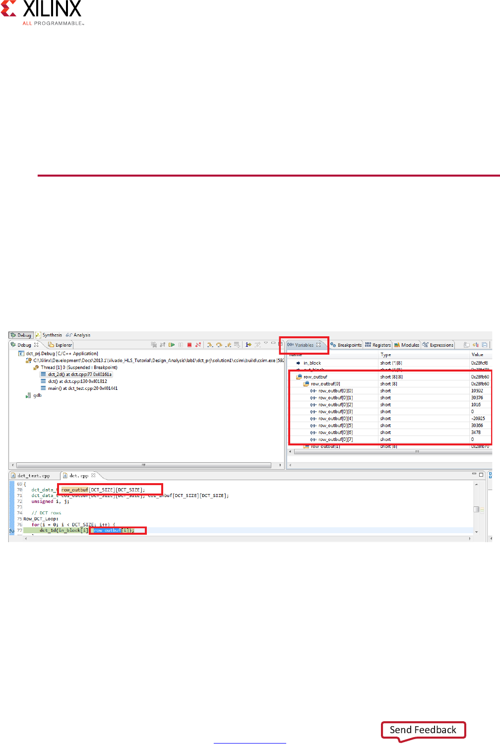
High-Level Synthesis 482
UG902 (v2017.1) April 5, 2017 www.xilinx.com
Chapter 4: High-Level Synthesis Reference Guide
Pragma
There is no pragma equivalent.
Examples
Sets the top-level function as foo_top.
set_top foo_top
GUI Reference
This reference section explains how to use, control and customize the Vivado HLS GUI.
Monitoring Variables
You can view the values of variables and expressions directly in the Debug perspective. The
following figure shows how you can monitor the value of individual variables.
X-Ref Target - Figure 4-1
Figure 4-1: Monitoring Variables
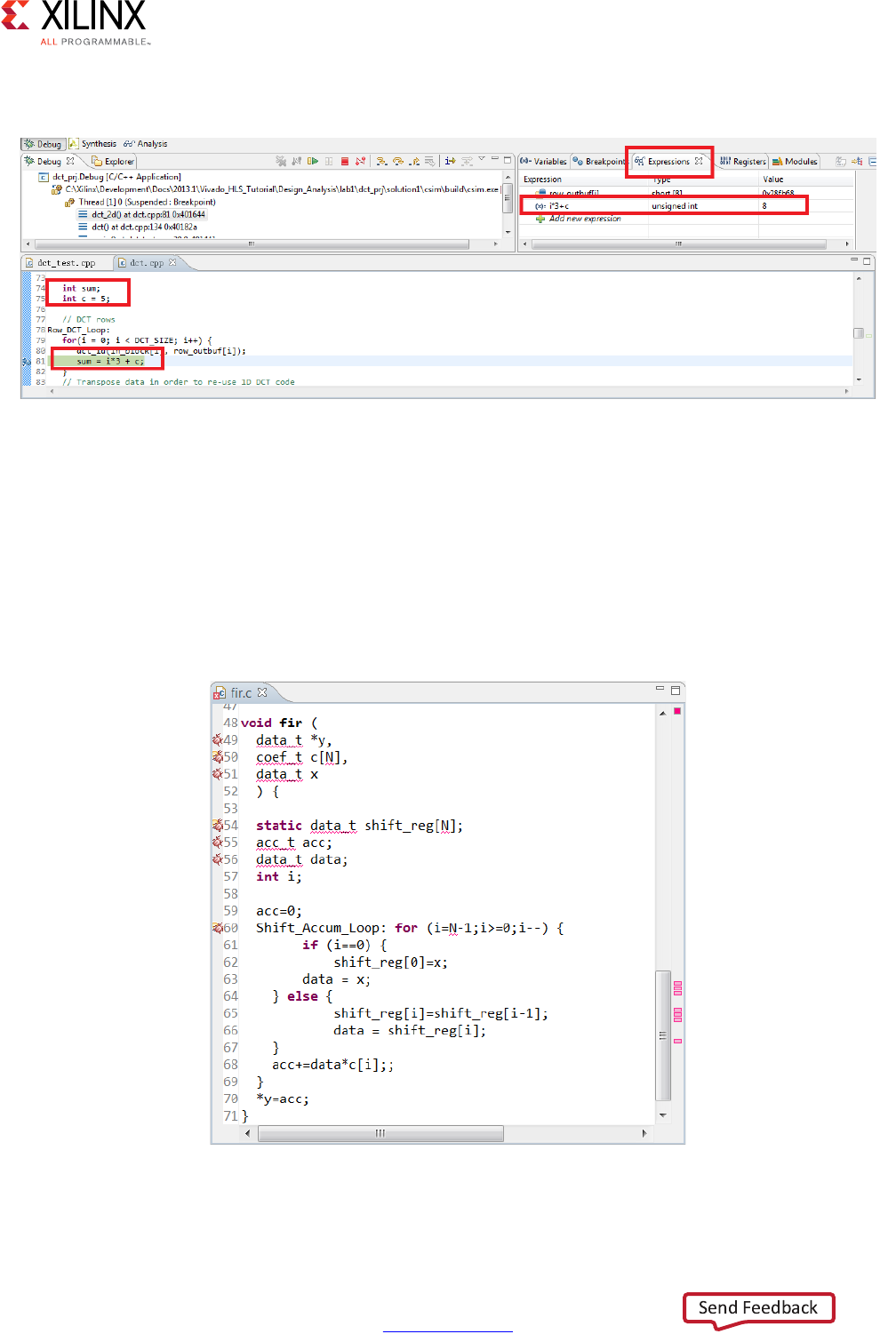
High-Level Synthesis 483
UG902 (v2017.1) April 5, 2017 www.xilinx.com
Chapter 4: High-Level Synthesis Reference Guide
You can monitor the value of expressions using the Expressions tab.
Resolving Header File Information
By default, the Vivado HLS GUI continually parses all header files to resolve coding
references. The GUI highlights unresolved references, as shown in the following figure:
• Left sidebar: Highlights undefined references in the current view.
• Right sidebar: Highlights unresolved references throughout the file.
0
X-Ref Target - Figure 4-2
Figure 4-2: Monitoring Expressions
X-Ref Target - Figure 4-3
Figure 4-3: Index C Files

High-Level Synthesis 484
UG902 (v2017.1) April 5, 2017 www.xilinx.com
Chapter 4: High-Level Synthesis Reference Guide
IMPORTANT: It is important to remove undefined references in the code before performing C
simulation or synthesis. To check for undefined references, see the annotations in the code viewer that
indicate a variable or value is unknown or cannot be defined. Undefined references do not appear in
the directives window.
Undefined references occur when code defined in a header file (.h or .hpp extension)
cannot be resolved. The primary causes of undefined references are:
• The code was recently added to the file.
If the code is new, ensure the header file is saved. After saving the header file, Vivado
HLS automatically indexes the header files and updates the coding references.
• The header file is not in the search path.
Ensure the header file is included in the C code using an include statement, the
location to the header file is in the search path, and the header file is in the same
directory as the C files added to the project.
Note: To explicitly add the search path, select Solution > Solution Settings, click Synthesis or
Simulation, and use the Edit CFLAGs button. For more information, see Creating a New
Synthesis Project in Chapter 1.
• Automatic indexing is disabled.
Ensure that Vivado HLS is parsing all header files automatically. Select Project > Project
Settings to open the Project Settings dialog box. Click General, and make sure Disable
Parsing All Header Files is deselected, as shown in the following figure. This might
result in a reduced GUI response time, because Vivado HLS uses CPU cycles to
automatically check the header files.
Note: To manually force Vivado HLS to index all C files, click the Index C files toolbar button
.
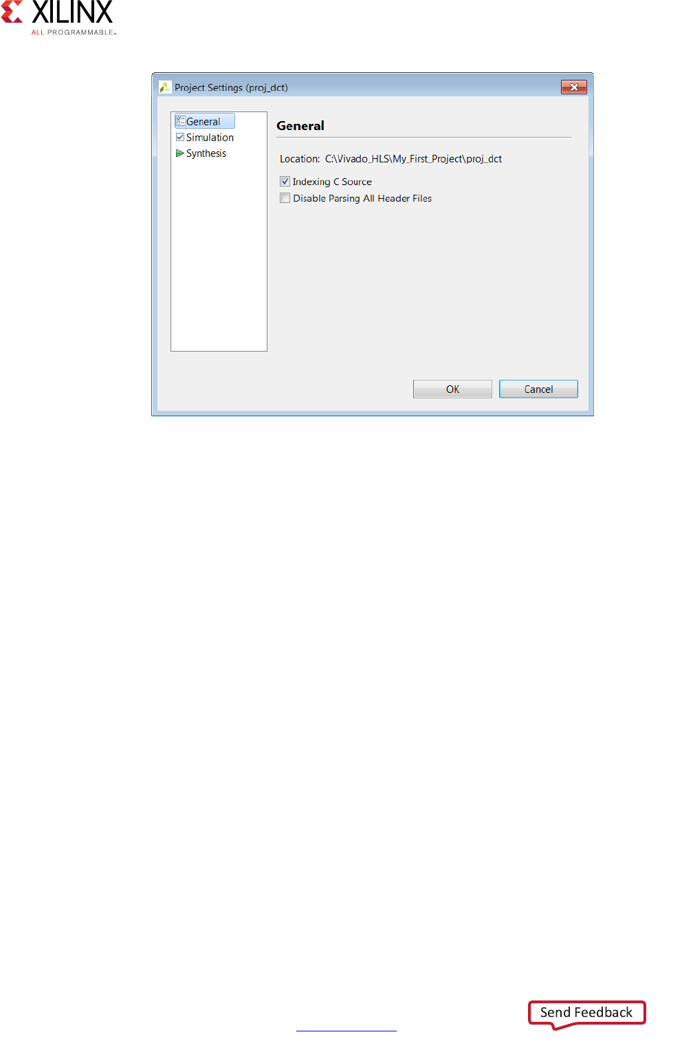
High-Level Synthesis 485
UG902 (v2017.1) April 5, 2017 www.xilinx.com
Chapter 4: High-Level Synthesis Reference Guide
Resolving Comments in the Source Code
In some localizations, non-English comments in the source file appears as strange
characters. This can be corrected by:
1. Selecting the project in the Explorer Pane.
2. Right-click and select the appropriate language encoding using Properties > Resource.
In the section titled Text File Encoding select Other and choose appropriate encoding
from the drop-down menu.
Customizing the GUI Behavior
In some cases the default setting of the Vivado HLS GUI prevents certain information from
being shown or the defaults that are not suitable for you. This sections explains how the
following can be customized:
• Console window buffer size.
• Default key behaviors.
Customizing the Console Window
The console windows displays the messages issued during operations such as synthesize
and verification.
X-Ref Target - Figure 4-4
Figure 4-4: Controlling Header File Parsing

High-Level Synthesis 486
UG902 (v2017.1) April 5, 2017 www.xilinx.com
Chapter 4: High-Level Synthesis Reference Guide
The default buffer size for this windows is 80,000 characters and can be changed, or the
limit can be removed, to ensure all messages can be reviewed, by using menu Window >
Preferences > Run/Debug > Console.
Customizing the Key Behavior
The behavior of the GUI can be customized using the menu Windows > Preferences and
new user-defined tool settings saved.
The default setting for the key combination Ctrl+Tab, is to make the active tab in the
Information Pane toggle between the source code and the header file. This is changed to
make the Ctrl+Tab combination make each tab in turn the active tab.
• In the Preferences menu, sub-menu General > Keys allows the Command value Toggle
Source/Header to be selected and the CTRL-TAB combination removed by using the
Unbind Command key.
• Selecting Next Tab in the Command column, placing the cursor in the Binding dialog
box and pressing the Ctrl key and then the Tab key, that causes the operation Ctrl+Tab
to be associated with making the next tab active.
A find-next hot key can be implemented by using the Microsoft Visual Studio scheme. This
can be performed using the menu Window > Preference > General > Keys and replace the
Default scheme with the Microsoft Visual Studio scheme.
Reviewing the sub-menus in the Preferences menu allows every aspect of the GUI
environment to be customized to ensure the highest levels of productivity.
Interface Synthesis Reference
This reference section explains each of the Vivado HLS interface protocol modes.
Block-Level I/O Protocols
Vivado HLS uses the interface types ap_ctrl_none, ap_ctrl_hs, and ap_ctrl_chain
to specify whether the RTL is implemented with block-level handshake signals. Block-level
handshake signals specify the following:
• When the design can start to perform the operation
• When the operation ends
• When the design is idle and ready for new inputs
You can specify these block-level I/O protocols on the function or the function return. If the
C code does not return a value, you can still specify the block-level I/O protocol on the
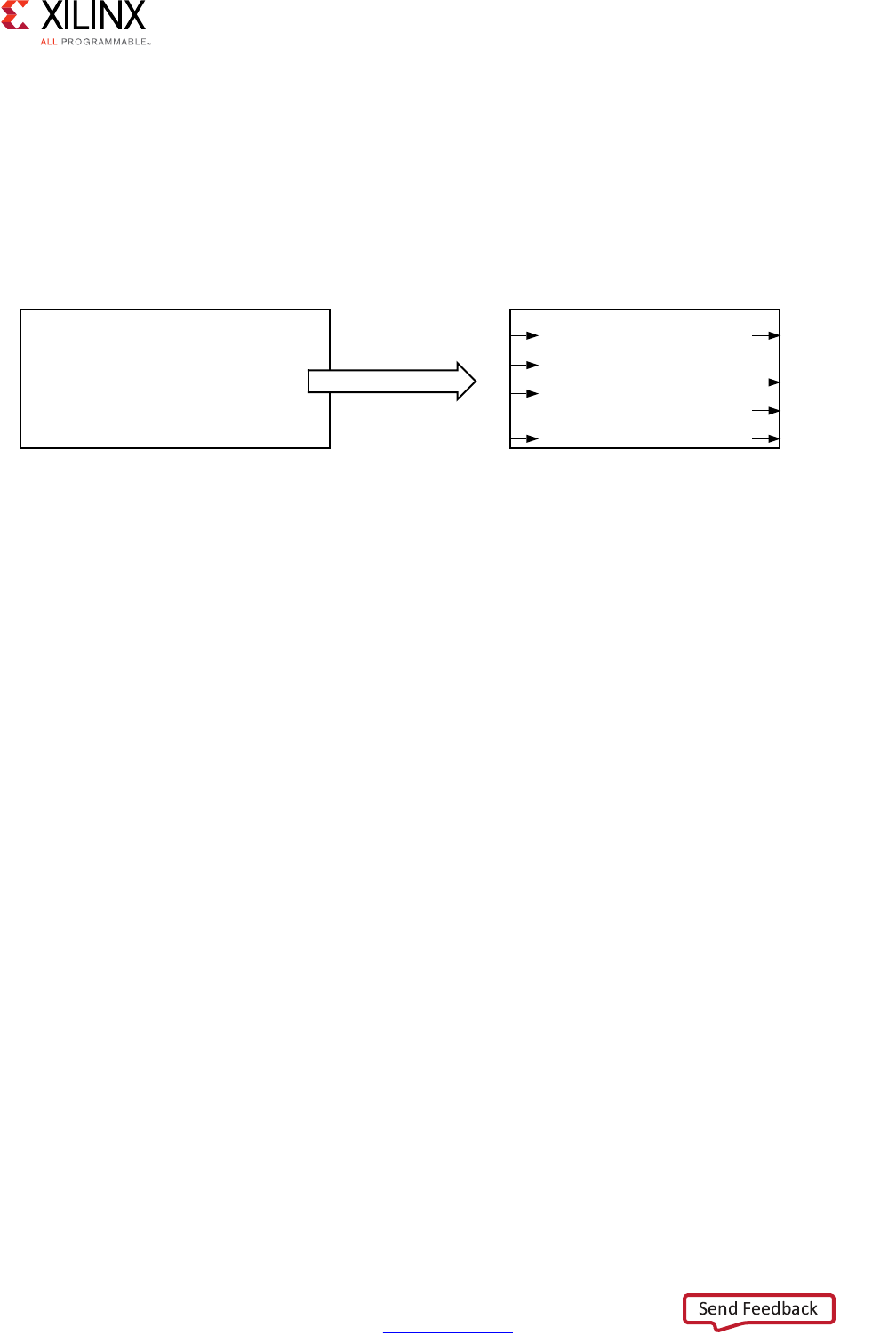
High-Level Synthesis 487
UG902 (v2017.1) April 5, 2017 www.xilinx.com
Chapter 4: High-Level Synthesis Reference Guide
function return. If the C code uses a function return, Vivado HLS creates an output port
ap_return for the return value.
The ap_ctrl_hs block-level I/O protocol is the default. The following figure shows the
resulting RTL ports and behavior when Vivado HLS implements ap_ctrl_hs on a function.
In this example, the function returns a value using the return statement, and Vivado HLS
creates the ap_return output port in the RTL design. If a function return statement is
not included in the C code, this port is not created.
The ap_ctrl_chain interface mode is similar to ap_ctrl_hs but provides an additional
input signal ap_continue to apply back pressure. Xilinx recommends using the
ap_ctrl_chain block-level I/O protocol when chaining Vivado HLS blocks together.
ap_ctrl_none
If you specify the ap_ctrl_none block-level I/O protocol, the handshake signal ports
(ap_start, ap_idle, ap_ready, and ap_done) shown in Figure 4-5 are not created. If
you do not specify block-level I/O protocols on the design, you must adhere to the
conditions described in Interface Synthesis Requirements in Chapter 1 when using C/RTL
cosimulation to verify the RTL design.
ap_ctrl_hs
The following figure shows the behavior of the block-level handshake signals created by the
ap_ctrl_hs I/O protocol.
X-Ref Target - Figure 4-5
Figure 4-5: Example ap_ctrl_hs Interface
#include “adders.h”
int adders(int in1, int in2, int in3) {
int sum;
sum = in1 + in2 + in3;
return sum;
}
DGGHUV
LQ
,Q
,Q
DSBVWDUW
DSBUHWXUQ
DSBUHDG\
DSBGRQH
DSBLGOH
6\QWKHVLV
;
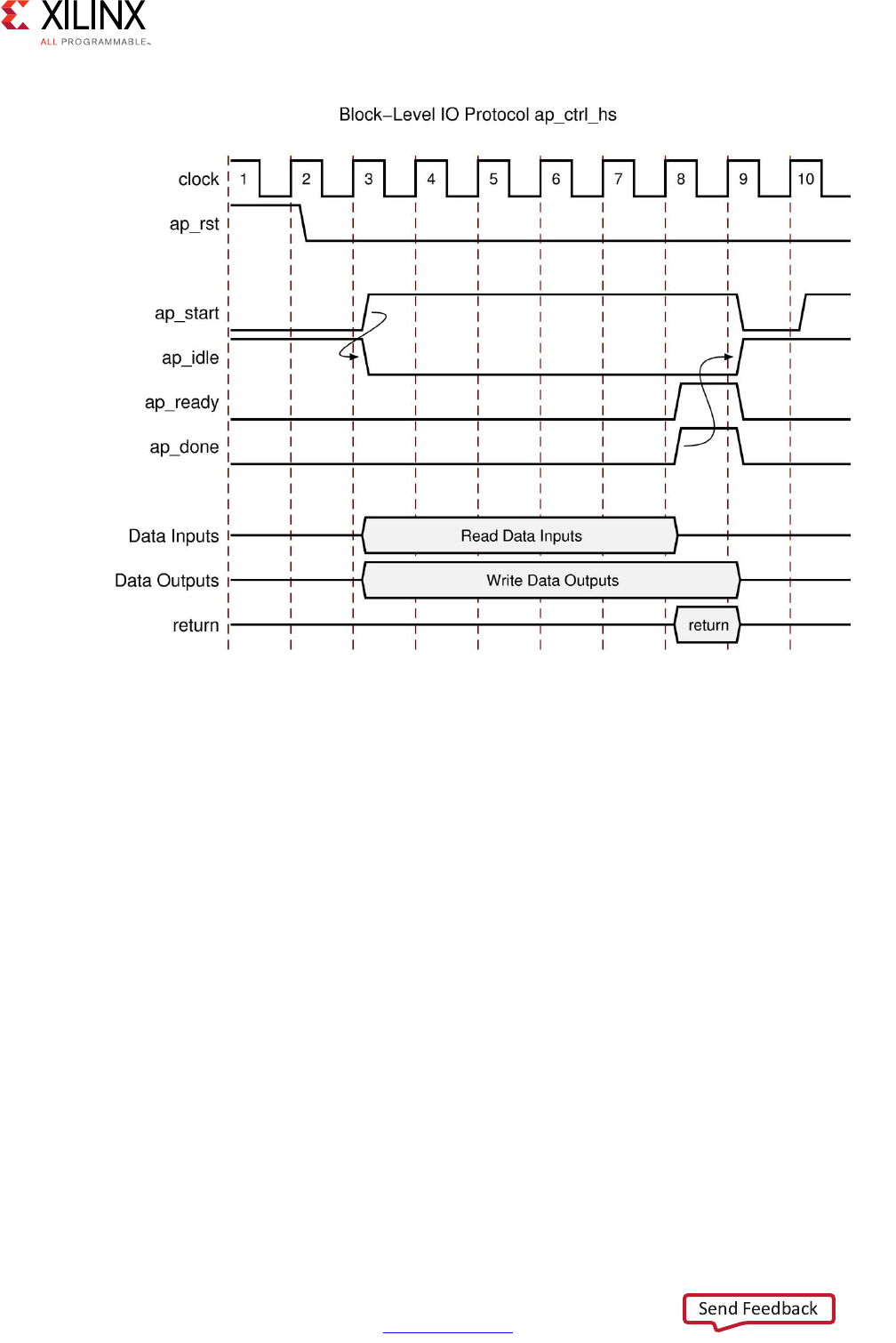
High-Level Synthesis 488
UG902 (v2017.1) April 5, 2017 www.xilinx.com
Chapter 4: High-Level Synthesis Reference Guide
After reset, the following occurs:
1. The block waits for ap_start to go High before it begins operation.
2. Output ap_idle goes Low immediately to indicate the design is no longer idle.
3. The ap_start signal must remain High until ap_ready goes High. Once ap_ready
goes High:
°If ap_start remains High the design will start the next transaction.
°If ap_start is taken Low, the design will complete the current transaction and halt
operation.
4. Data can be read on the input ports.
Note: The input ports can use a port-level I/O protocol that is independent of this block-level
I/O protocol. For details, see Port-Level I/O Protocols.
5. Data can be written to the output ports.
Note: The output ports can use a port-level I/O protocol that is independent of this block-level
I/O protocol. For details, see Port-Level I/O Protocols.
X-Ref Target - Figure 4-6
Figure 4-6: Behavior of ap_ctrl_hs Interface

High-Level Synthesis 489
UG902 (v2017.1) April 5, 2017 www.xilinx.com
Chapter 4: High-Level Synthesis Reference Guide
6. Output ap_done goes High when the block completes operation.
Note: If there is an ap_return port, the data on this port is valid when ap_done is High.
Therefore, the ap_done signal also indicates when the data on output ap_return is valid.
7. When the design is ready to accept new inputs, the ap_ready signal goes High.
Following is additional information about the ap_ready signal:
°The ap_ready signal is inactive until the design starts operation.
°In non-pipelined designs, the ap_ready signal is asserted at the same time as
ap_done.
°In pipelined designs, the ap_ready signal might go High at any cycle after
ap_start is sampled High. This depends on how the design is pipelined.
°If the ap_start signal is Low when ap_ready is High, the design executes until
ap_done is High and then stops operation.
°If the ap_start signal is High when ap_ready is High, the next transaction starts
immediately, and the design continues to operate.
8. The ap_idle signal indicates when the design is idle and not operating. Following is
additional information about the ap_idle signal:
°If the ap_start signal is Low when ap_ready is High, the design stops operation,
and the ap_idle signal goes High one cycle after ap_done.
°If the ap_start signal is High when ap_ready is High, the design continues to
operate, and the ap_idle signal remains Low.
ap_ctrl_chain
The ap_ctrl_chain block-level I/O protocol is similar to the ap_ctrl_hs protocol but
provides an additional input port named ap_continue. An active High ap_continue
signal indicates that the downstream block that consumes the output data is ready for new
data inputs. If the downstream block is not able to consume new data inputs, the
ap_continue signal is Low, which prevents upstream blocks from generating additional
data.
The ap_ready port of the downstream block can directly drive the ap_continue port.
Following is additional information about the ap_continue port:
•If the ap_continue signal is High when ap_done is High, the design continues
operating. The behavior of the other block-level I/O signals is identical to those
described in the ap_ctrl_hs block-level I/O protocol.
•If the ap_continue signal is Low when ap_done is High, the design stops operating,
the ap_done signal remains High, and data remains valid on the ap_return port if
the ap_return port is present.
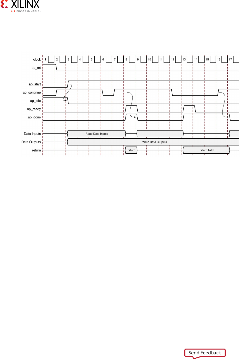
High-Level Synthesis 490
UG902 (v2017.1) April 5, 2017 www.xilinx.com
Chapter 4: High-Level Synthesis Reference Guide
In the following figure, the first transaction completes, and the second transaction starts
immediately because ap_continue is High when ap_done is High. However, the design
halts at the end of the second transaction until ap_continue is asserted High.
Port-Level I/O Protocols
ap_none
The ap_none port-level I/O protocol is the simplest interface type and has no other signals
associated with it. Neither the input nor output data signals have associated control ports
that indicate when data is read or written. The only ports in the RTL design are those
specified in the source code.
X-Ref Target - Figure 4-7
Figure 4-7: Behavior of ap_ctrl_chain Interface

High-Level Synthesis 491
UG902 (v2017.1) April 5, 2017 www.xilinx.com
Chapter 4: High-Level Synthesis Reference Guide
An ap_none interface does not require additional hardware overhead. However, the
ap_none interface does requires the following:
• Producer blocks to do one of the following:
°Provide data to the input port at the correct time
°Hold data for the length of a transaction until the design completes
• Consumer blocks to read output ports at the correct time
Note: The ap_none interface cannot be used with array arguments.
ap_stable
Like ap_none, the ap_stable port-level I/O protocol does not add any interface control
ports to the design. The ap_stable type is typically used for data that can change but
remains stable during normal operation, such as ports that provide configuration data. The
ap_stable type informs Vivado HLS of the following:
• The data applied to the port remains stable during normal operation but is not a
constant value that can be optimized.
• The fanout from this port is not required to be registered.
Note: The ap_stable type can only be applied to input ports. When applied to inout ports, only
the input of the port is considered stable.
ap_hs (ap_ack, ap_vld, and ap_ovld)
The ap_hs port-level I/O protocol provides the greatest flexibility in the development
process, allowing both bottom-up and top-down design flows. Two-way handshakes safely
perform all intra-block communication, and manual intervention or assumptions are not
required for correct operation. The ap_hs port-level I/O protocol provides the following
signals:
• Data port
• Acknowledge signal to indicate when data is consumed
• Valid signal to indicate when data is read
The following figure shows how an ap_hs interface behaves for both an input and output
port. In this example, the input port is named in, and the output port is named out.
Note: The control signals names are based on the original port name. For example, the valid port for
data input in is named in_vld.
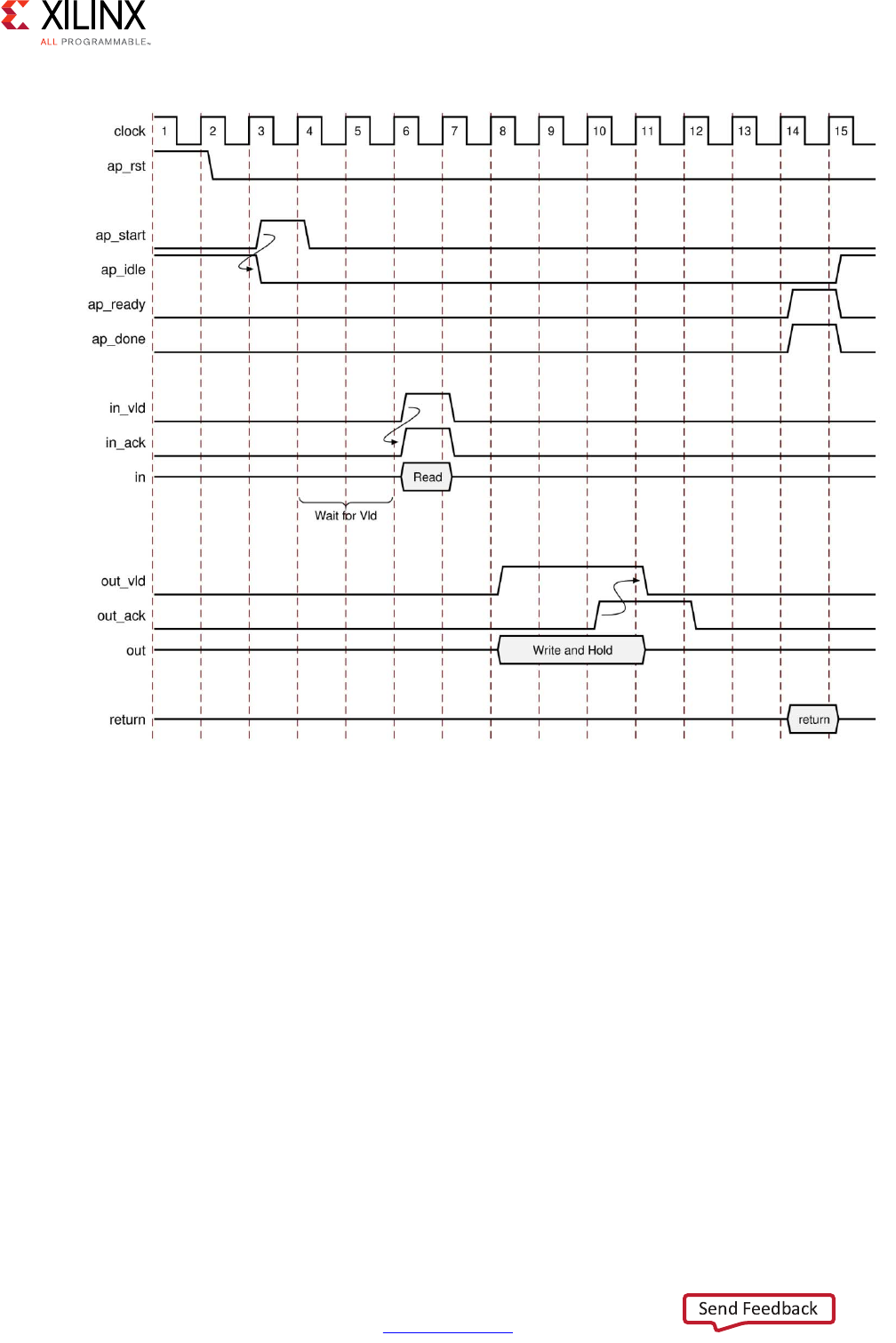
High-Level Synthesis 492
UG902 (v2017.1) April 5, 2017 www.xilinx.com
Chapter 4: High-Level Synthesis Reference Guide
For inputs, the following occurs:
• After start is applied, the block begins normal operation.
• If the design is ready for input data but the input valid is Low, the design stalls and
waits for the input valid to be asserted to indicate a new input value is present.
Note: The preceding figure shows this behavior. In this example, the design is ready to read data
input in on clock cycle 4 and stalls waiting for the input valid before reading the data.
• When the input valid is asserted High, an output acknowledge is asserted High to
indicate the data was read.
X-Ref Target - Figure 4-8
Figure 4-8: Behavior of ap_hs Interface
High-Level Synthesis 493
UG902 (v2017.1) April 5, 2017 www.xilinx.com
Chapter 4: High-Level Synthesis Reference Guide
For outputs, the following occurs:
• After start is applied, the block begins normal operation.
• When an output port is written to, its associated output valid signal is simultaneously
asserted to indicate valid data is present on the port.
• If the associated input acknowledge is Low, the design stalls and waits for the input
acknowledge to be asserted.
• When the input acknowledge is asserted, the output valid is deasserted on the next
clock edge.
ap_ack
The ap_ack port-level I/O protocol is a subset of the ap_hs interface type. The ap_ack
port-level I/O protocol provides the following signals:
• Data port
• Acknowledge signal to indicate when data is consumed
°For input arguments, the design generates an output acknowledge that is
active-High in the cycle the input is read.
°For output arguments, Vivado HLS implements an input acknowledge port to
confirm the output was read.
Note: After a write operation, the design stalls and waits until the input acknowledge is asserted
High, which indicates the output was read by a consumer block. However, there is no associated
output port to indicate when the data can be consumed.
CAUTION! You cannot use C/RTL cosimulation to verify designs that use ap_ack on an output port.
ap_vld
The ap_vld is a subset of the ap_hs interface type. The ap_vld port-level I/O protocol
provides the following signals:
• Data port
• Valid signal to indicate when data is read
°For input arguments, the design reads the data port as soon as the valid is active.
Even if the design is not ready to read new data, the design samples the data port
and holds the data internally until needed.
°For output arguments, Vivado HLS implements an output valid port to indicate
when the data on the output port is valid.

High-Level Synthesis 494
UG902 (v2017.1) April 5, 2017 www.xilinx.com
Chapter 4: High-Level Synthesis Reference Guide
ap_ovld
The ap_ovld is a subset of the ap_hs interface type. The ap_ovld port-level I/O protocol
provides the following signals:
• Data port
• Valid signal to indicate when data is read
°For input arguments and the input half of inout arguments, the design defaults to
type ap_none.
°For output arguments and the output half of inout arguments, the design
implements type ap_vld.
ap_memory, bram
The ap_memory and bram interface port-level I/O protocols are used to implement array
arguments. This type of port-level I/O protocol can communicate with memory elements
(for example, RAMs and ROMs) when the implementation requires random accesses to the
memory address locations.
Note: If you only need sequential access to the memory element, use the ap_fifo interface
instead. The ap_fifo interface reduces the hardware overhead, because address generation is not
performed. For more information, see ap_fifo.
The ap_memory and bram interface port-level I/O protocols are identical. The only
difference is the way Vivado IP integrator shows the blocks:
•The ap_memory interface appears as discrete ports.
•The bram interface appears as a single, grouped port. In IP integrator, you can use a
single connection to create connections to all ports.
When using an ap_memory interface, specify the array targets using the RESOURCE
directive. If no target is specified for the arrays, Vivado HLS determines whether to use a
single or dual-port RAM interface.
TIP: Before running synthesis, ensure array arguments are targeted to the correct memory type using
the RESOURCE directive. Re-synthesizing with corrected memories can result in a different schedule
and RTL.
The following figure shows an array named d specified as a single-port block RAM. The port
names are based on the C function argument. For example, if the C argument is d, the
chip-enable is d_ce, and the input data is d_q0 based on the output/q port of the BRAM.
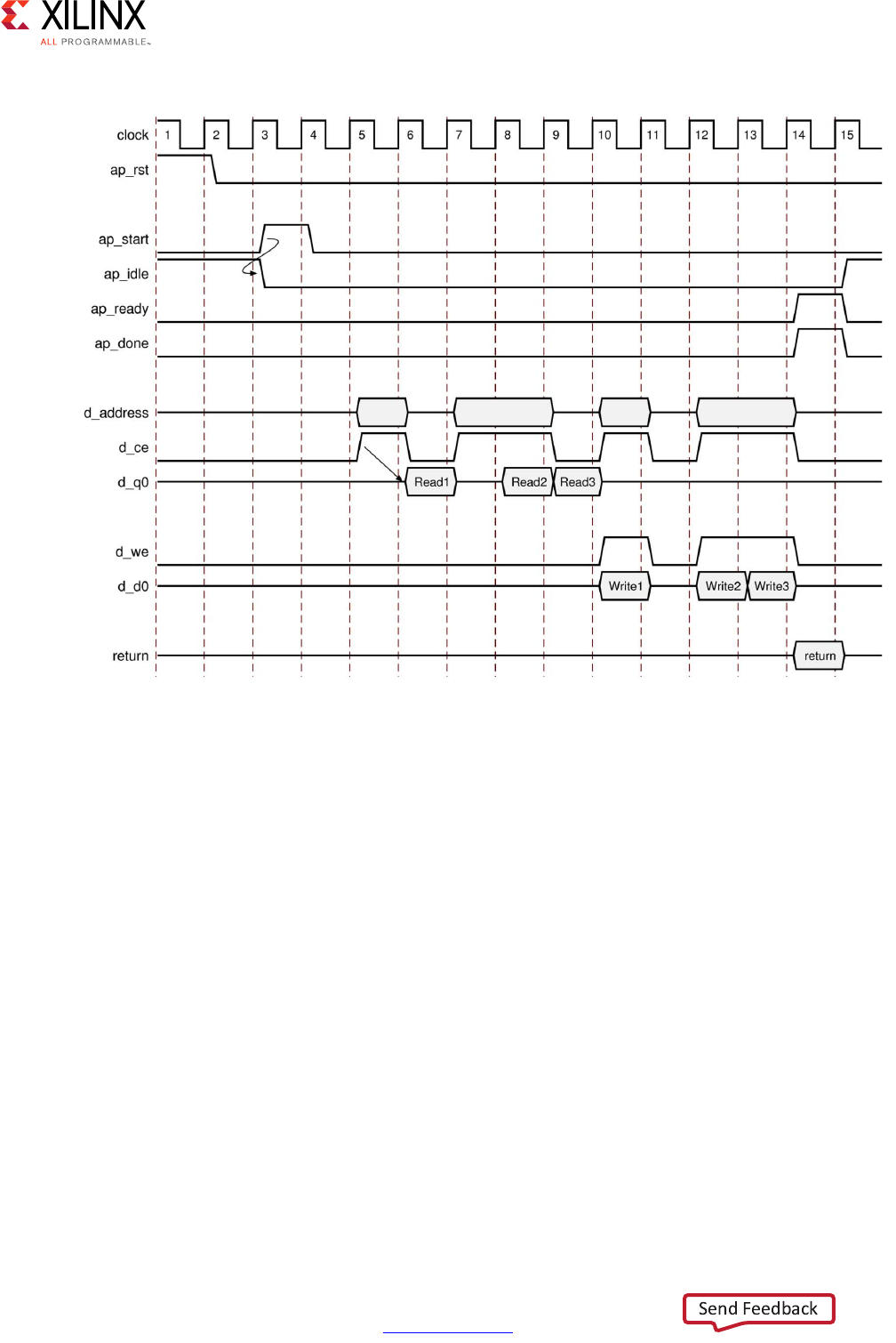
High-Level Synthesis 495
UG902 (v2017.1) April 5, 2017 www.xilinx.com
Chapter 4: High-Level Synthesis Reference Guide
After reset, the following occurs:
• After start is applied, the block begins normal operation.
• Reads are performed by applying an address on the output address ports while
asserting the output signal d_ce.
Note: For a default block RAM, the design expects the input data d_q0 to be available in the
next clock cycle. You can use the RESOURCE directive to indicate the RAM has a longer read
latency.
• Write operations are performed by asserting output ports d_ce and d_we while
simultaneously applying the address and output data d_d0.
X-Ref Target - Figure 4-9
Figure 4-9: Behavior of ap_memory Interface

High-Level Synthesis 496
UG902 (v2017.1) April 5, 2017 www.xilinx.com
Chapter 4: High-Level Synthesis Reference Guide
ap_fifo
An ap_fifo interface is the most hardware-efficient approach when the design requires
access to a memory element and the access is always performed in a sequential manner,
that is, no random access is required. The ap_fifo port-level I/O protocol supports the
following:
• Allows the port to be connected to a FIFO
• Enables complete, two-way empty-full communication
• Works for arrays, pointers, and pass-by-reference argument types
Note: Functions that can use an ap_fifo interface often use pointers and might access the same
variable multiple times. To understand the importance of the volatile qualifier when using this
coding style, see Multi-Access Pointer Interfaces: Streaming Data in Chapter 3.
In the following example, in1 is a pointer that accesses the current address, then two
addresses above the current address, and finally one address below.
void foo(int* in1, ...) {
int data1, data2, data3;
...
data1= *in1;
data2= *(in1+2);
data3= *(in1-1);
...
}
If in1 is specified as an ap_fifo interface, Vivado HLS checks the accesses, determines
the accesses are not in sequential order, issues an error, and halts. To read from
non-sequential address locations, use an ap_memory or bram interface. For more
information, see ap_memory, bram.
You cannot specify an ap_fifo interface on an argument that is both read from and
written to. You can only specify an ap_fifo interface on an input or an output argument.
A design with input argument in and output argument out specified as ap_fifo
interfaces behaves as shown in the following figure.
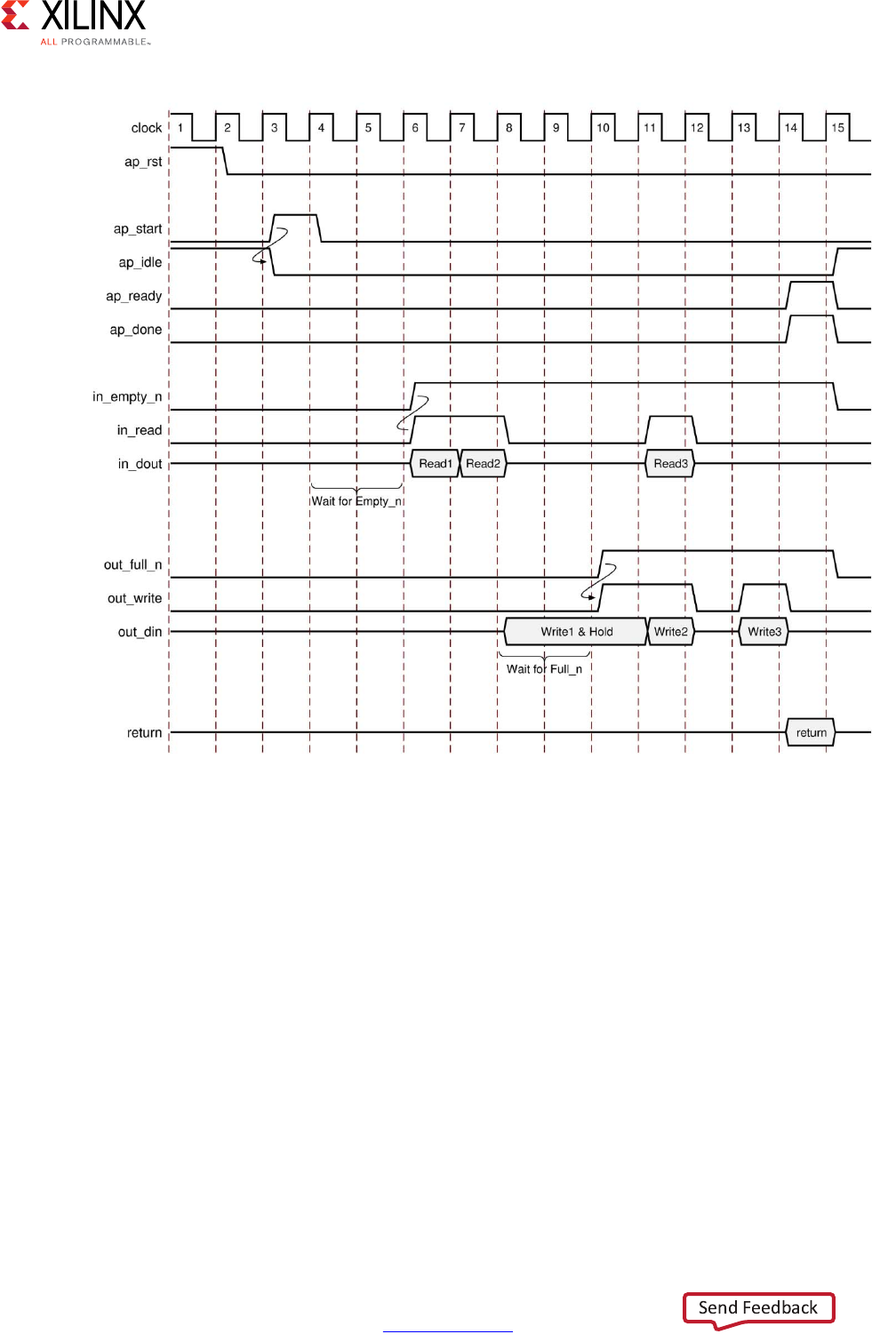
High-Level Synthesis 497
UG902 (v2017.1) April 5, 2017 www.xilinx.com
Chapter 4: High-Level Synthesis Reference Guide
For inputs, the following occurs:
• After start is applied, the block begins normal operation.
• If the input port is ready to be read but the FIFO is empty as indicated by input port
in_empty_n Low, the design stalls and waits for data to become available.
• When the FIFO contains data as indicated by input port in_empty_n High, an output
acknowledge in_read is asserted High to indicate the data was read in this cycle.
X-Ref Target - Figure 4-10
Figure 4-10: Behavior of ap_fifo Interface

High-Level Synthesis 498
UG902 (v2017.1) April 5, 2017 www.xilinx.com
Chapter 4: High-Level Synthesis Reference Guide
For outputs, the following occurs:
• After start is applied, the block begins normal operation.
• If an output port is ready to be written to but the FIFO is full as indicated by
out_full_n Low, the data is placed on the output port but the design stalls and waits
for the space to become available in the FIFO.
• When space becomes available in the FIFO as indicated by out_full_n High, the
output acknowledge signal out_write is asserted to indicate the output data is valid.
• If the top-level function or the top-level loop is pipelined using the -rewind option,
Vivado HLS creates an additional output port with the suffix _lwr. When the last write
to the FIFO interface completes, the _lwr port goes active-High.
ap_bus
An ap_bus interface can communicate with a bus bridge. Because the ap_bus interface
does not follow specific bus standards, you can use this interface with a bus bridge that
communicates with the system bus. The bus bridge must be able to cache all burst writes.
Note: Functions that can use an ap_bus interface use pointers and might access the same variable
multiple times. To understand the importance of the volatile qualifier when using this coding
style, see Multi-Access Pointer Interfaces: Streaming Data in Chapter 3.
You can use an ap_bus interface in the following ways:
• Standard Mode: This mode performs individual read and write operations, specifying
the address of each.
• Burst Mode: This mode performs data transfers if the C function memcpy is used in the
C source code. In burst mode, the interface indicates the base address and the size of
the transfer. The data samples are then transferred in consecutive cycles.
Note: Arrays accessed by the memcpy function cannot be partitioned into registers.
Figure 4-11 and Figure 4-12 show the behavior for read and write operations in standard
mode when an ap_bus interface is applied to argument d, as shown in the following
example:
void foo (int *d) {
static int acc = 0;
int i;
for (i=0;i<4;i++) {
acc += d[i+1];
d[i] = acc;
}
}
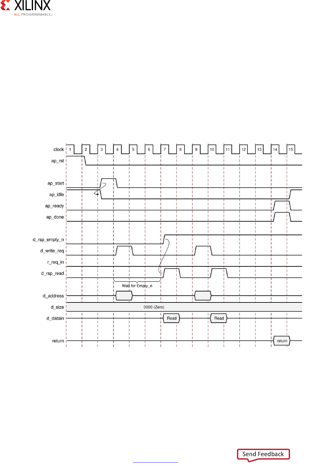
High-Level Synthesis 499
UG902 (v2017.1) April 5, 2017 www.xilinx.com
Chapter 4: High-Level Synthesis Reference Guide
Figure 4-13 and Figure 4-14 show the behavior when the C memcpy function and burst
mode are used, as shown in the following example:
void bus (int *d) {
int buf1[4], buf2[4];
int i;
memcpy(buf1,d,4*sizeof(int));
for (i=0;i<4;i++) {
buf2[i] = buf1[3-i];
}
memcpy(d,buf2,4*sizeof(int));
}
,
X-Ref Target - Figure 4-11
Figure 4-11: Behavior of ap_bus Interface: Standard Read

High-Level Synthesis 500
UG902 (v2017.1) April 5, 2017 www.xilinx.com
Chapter 4: High-Level Synthesis Reference Guide
After reset, the following occurs:
• After start, the block begins normal operation.
• If a read must be performed but there is no data in the bus bridge FIFO, indicated by
d_rsp_empty_n Low, the following occurs:
°Output port d_req_write is asserted with port d_req_din deasserted to indicate
a read operation.
°The address is output.
°The design stalls and waits for data to become available.
• When data becomes available for reading the output signal, d_rsp_read is
immediately asserted and data is read at the next clock edge.
• If a read must be performed and data is available in the bus bridge FIFO, indicated by
d_rsp_empty_n High, the following occurs:
°Output port d_req_write is asserted and port d_req_din is deasserted to
indicate a read operation.
°The address is output.
°Output signal d_rsp_read is asserted in the next clock cycle and data is read at
the next clock edge.
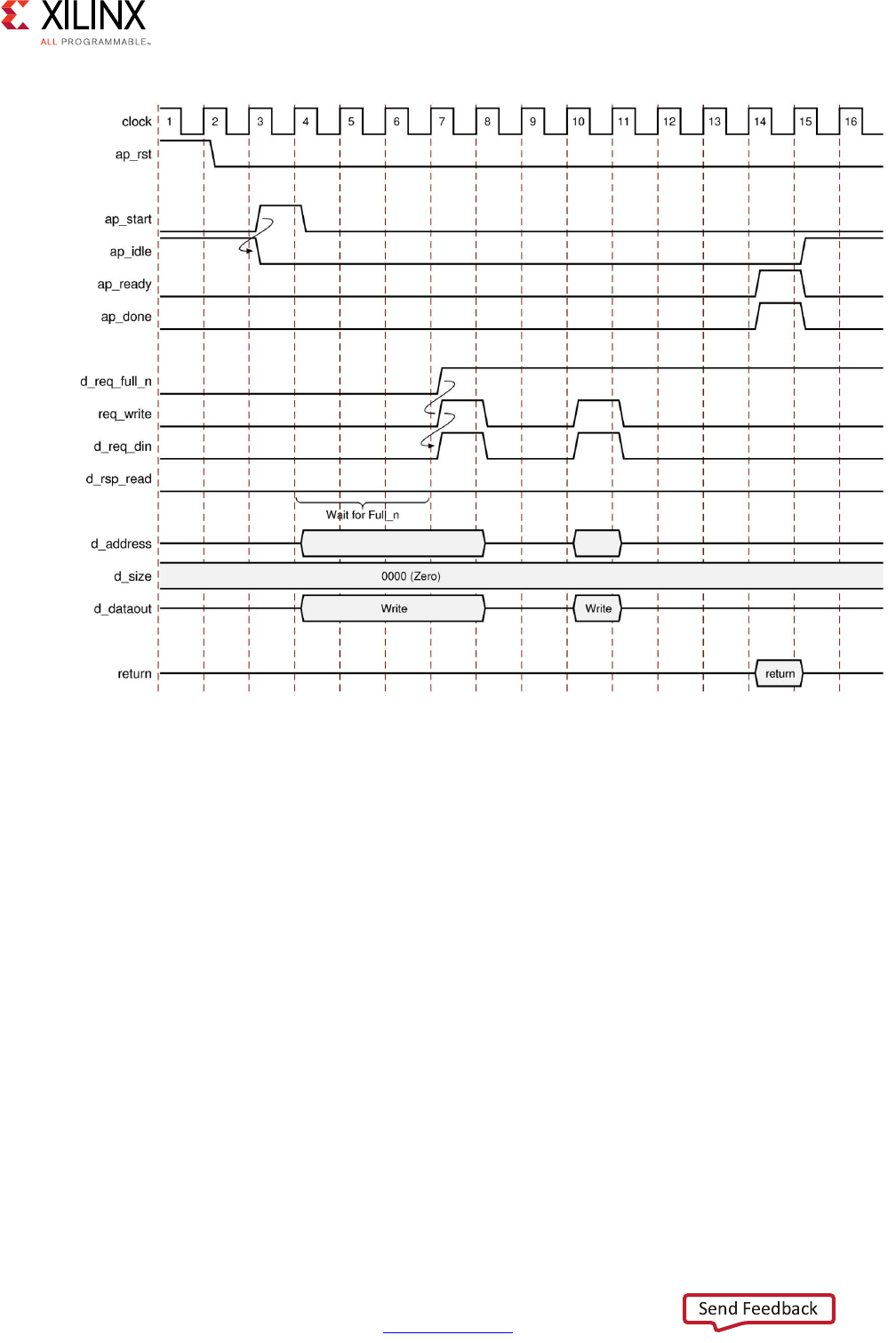
High-Level Synthesis 501
UG902 (v2017.1) April 5, 2017 www.xilinx.com
Chapter 4: High-Level Synthesis Reference Guide
After reset, the following occurs:
• After start, the block begins normal operation.
• If a write must be performed but there is no space in the bus bridge FIFO, indicated by
d_req_full_n Low, the following occurs:
°The address and data are output.
°The design stalls and waits for space to become available.
X-Ref Target - Figure 4-12
Figure 4-12: Behavior of ap_bus Interface: Standard Write
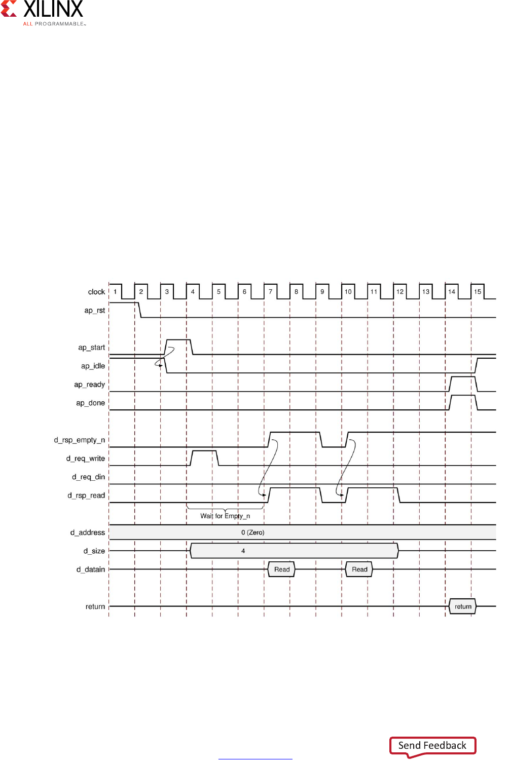
High-Level Synthesis 502
UG902 (v2017.1) April 5, 2017 www.xilinx.com
Chapter 4: High-Level Synthesis Reference Guide
• When space becomes available for writing, the following occurs:
°Output ports d_req_write and d_req_din are asserted to indicate a write
operation.
°The output signal d_req_din is immediately asserted to indicate the data is valid
at the next clock edge.
• If a write must be performed and space is available in the bus bridge FIFO, indicated by
d_req_full_n High, the following occurs:
°Output ports d_req_write and d_req_din are asserted to indicate a write
operation.
°The address and data are output.
°The output signal d_req_din is asserted to indicate the data is valid at the next
clock edge.
X-Ref Target - Figure 4-13
Figure 4-13: Behavior of ap_bus Interface: Burst Read
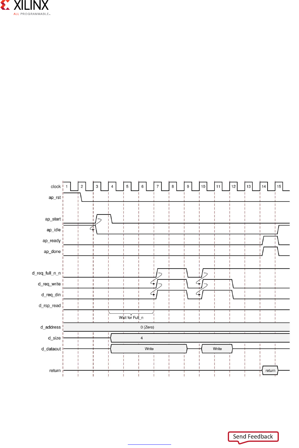
High-Level Synthesis 503
UG902 (v2017.1) April 5, 2017 www.xilinx.com
Chapter 4: High-Level Synthesis Reference Guide
After reset, the following occurs:
• After start, the block begins normal operation.
• If a read must be performed but there is no data in the bus bridge FIFO, indicated by
d_rsp_empty_n Low, the following occurs:
°Output port d_req_write is asserted with port d_req_din deasserted to indicate
a read operation.
°The base address for the transfer and the size are output.
°The design stalls and waits for data to become available.
• When data becomes available for reading the output signal, d_rsp_read is
immediately asserted and data is read at the next N clock edges, where N is the value
on output port size.
• If the bus bridge FIFO runs empty of values, the data transfers stop immediately and
wait until data is available before continuing.
X-Ref Target - Figure 4-14
Figure 4-14: Behavior of ap_bus Interface: Burst Write

High-Level Synthesis 504
UG902 (v2017.1) April 5, 2017 www.xilinx.com
Chapter 4: High-Level Synthesis Reference Guide
After reset, the following occurs:
• After start, the block begins normal operation.
• If a write must be performed but there is no space in the bus bridge FIFO, indicated by
d_req_full_n Low, the following occurs:
°The base address, transfer size, and data are output.
°The design stalls and waits for space to become available.
• When space becomes available for writing, the following occurs:
°Output ports d_req_write and d_req_din are asserted to indicate a write
operation.
°The output signal d_req_din is immediately asserted to indicate the data is valid
at the next clock edge.
°Output signal d_req_din is immediately deasserted if the FIFO becomes full and
reasserted when space is available.
°The transfer stops after N data values are transferred, where N is the value on the
size output port.
• If a write must be performed and space is available in the bus bridge FIFO, indicated by
d_rsp_full_n High, transfer begins and the design stalls and waits until the FIFO is
full.
axis
The axis mode specifies an AXI4-Stream I/O protocol. For a complete description of the
AXI4-Stream interface, including timing and ports, see the Vivado Design Suite AXI
Reference Guide (UG1037) [Ref 8]. For information on using the full capabilities of this I/O
protocol, see Using AXI4 Interfaces in Chapter 1.
s_axilite
The s_axilite mode specifies an AXI4-Lite slave I/O protocol. For a complete description
of the AXI4-Lite slave interface, including timing and ports, see the Vivado Design Suite AXI
Reference Guide (UG1037) [Ref 8]. For information on using the full capabilities of this I/O
protocol, see Using AXI4 Interfaces in Chapter 1.
m_axi
The m_axi mode specifies an AXI4 master I/O protocol. For a complete description of the
AXI4 master interface including timing and ports, see the Vivado Design Suite AXI Reference
Guide (UG1037) [Ref 8]. For information on using the full capabilities of this I/O protocol,
see Using AXI4 Interfaces in Chapter 1.

High-Level Synthesis 505
UG902 (v2017.1) April 5, 2017 www.xilinx.com
Chapter 4: High-Level Synthesis Reference Guide
AXI4-Lite Slave C Driver Reference
When an AXI4-Lite slave interface is added to the design, a set of C driver files are
automatically created. These C driver files provide a set of APIs that can be integrated into
any software running on a CPU and used to communicate with the device using the
AXI4-Lite interface.
The API functions derive their name from the top-level function for synthesis. This reference
section assumes the top-level function is called DUT. The following table lists each of the
API function provided in the C driver files.
Table 4-1: C Driver API Functions
API Function Description
XDut_Initialize This API will write value to InstancePtr which then can be used
in other APIs. Xilinx recommends calling this API to initialize a
device except when an MMU is used in the system.
XDut_CfgInitialize Initialize a device configuration. When a MMU is used in the
system, replace the base address in the XDut_Config variable
with virtual base address before calling this function. Not for
use on Linux systems.
XDut_LookupConfig Used to obtain the configuration information of the device by
ID. The configuration information contain the physical base
address. Not for use on Linux.
XDut_Release Release the uio device in linux. Delete the mappings by
munmap: the mapping will automatically be deleted if the
process terminated. Only for use on Linux systems.
XDut_Start Start the device. This function will assert the ap_start port on
the device. Available only if there is ap_start port on the
device.
XDut_IsDone Check if the device has finished the previous execution: this
function will return the value of the ap_done port on the device.
Available only if there is an ap_done port on the device.
XDut_IsIdle Check if the device is in idle state: this function will return the
value of the ap_idle port. Available only if there is an ap_idle
port on the device.
XDut_IsReady Check if the device is ready for the next input: this function will
return the value of the ap_ready port. Available only if there is
an ap_ready port on the device.
XDut_Continue Assert port ap_continue. Available only if there is an
ap_continue port on the device.
XDut_EnableAutoRestart Enables “auto restart” on device. When this is set the device will
automatically start the next transaction when the current
transaction completes.
XDut_DisableAutoRestart Disable the “auto restart” function.

High-Level Synthesis 506
UG902 (v2017.1) April 5, 2017 www.xilinx.com
Chapter 4: High-Level Synthesis Reference Guide
XDut_Set_ARG Write a value to port ARG (a scalar argument of the top
function). Available only if ARG is input port.
XDut_Set_ARG_vld Assert port ARG_vld. Available only if ARG is an input port and
implemented with an ap_hs or ap_vld interface protocol.
XDut_Set_ARG_ack Assert port ARG_ack. Available only if ARG is an output port and
implemented with an ap_hs or ap_ack interface protocol.
XDut_Get_ARG Read a value from ARG. Only available if port ARG is an output
port on the device.
XDut_Get_ARg_vld Read a value from ARG_vld. Only available if port ARG is an
output port on the device and implemented with an ap_hs or
ap_vld interface protocol.
XDut_Get_ARg_ack Read a value from ARG_ack. Only available if port ARG is an
input port on the device and implemented with an ap_hs or
ap_ack interface protocol.
XDut_Get_ARG_BaseAddress Return the base address of the array inside the interface. Only
available when ARG is an array grouped into the AXI4-Lite
interface.
XDut_Get_ARG_HighAddress Return the address of the uppermost element of the array. Only
available when ARG is an array grouped into the AXI4-Lite
interface.
XDut_Get_ARG_TotalBytes Return the total number of bytes used to store the array. Only
available when ARG is an array grouped into the AXI4-Lite
interface.
Note: If the elements in the array are less than 16-bit, Vivado HLS
groups multiple elements into the 32-bit data width of the AXI4-Lite
interface. If the bit width of the elements exceeds 32-bit, Vivado HLS
stores each element over multiple consecutive addresses.
XDut_Get_ARG_BitWidth Return the bit width of each element in the array. Only available
when ARG is an array grouped into the AXI4-Lite interface.
Note: If the elements in the array are less than 16-bit, Vivado HLS
groups multiple elements into the 32-bit data width of the AXI4-Lite
interface. If the bit width of the elements exceeds 32-bit, Vivado HLS
stores each element over multiple consecutive addresses.
XDut_Get_ARG_Depth Return the total number of elements in the array. Only available
when ARG is an array grouped into the AXI4-Lite interface.
Note: If the elements in the array are less than 16-bit, Vivado HLS
groups multiple elements into the 32-bit data width of the AXI4-Lite
interface. If the bit width of the elements exceeds 32-bit, Vivado HLS
stores each element over multiple consecutive addresses.
XDut_Write_ARG_Words Write the length of a 32-bit word into the specified address of
the AXI4-Lite interface. This API requires the offset address
from BaseAddress and the length of the data to be stored. Only
available when ARG is an array grouped into the AXI4-Lite
interface.
Table 4-1: C Driver API Functions (Cont’d)
API Function Description

High-Level Synthesis 507
UG902 (v2017.1) April 5, 2017 www.xilinx.com
Chapter 4: High-Level Synthesis Reference Guide
The details on the API functions are provided below.
XDut_Initialize
Synopsis
int XDut_Initialize(XDut *InstancePtr, u16 DeviceId);
int XDut_Initialize(XDut *InstancePtr, const char* InstanceName);
Description
int XDut_Initialize(XDut *InstancePtr, u16 DeviceId): For use on standalone systems,
initialize a device. This API will write a proper value to InstancePtr which then can be used
in other APIs. Xilinx recommends calling this API to initialize a device except when an MMU
is used in the system, in which case refer to function XDut_CfgInitialize.
int XDut_Initialize(XDut *InstancePtr, const char* InstanceName): For use on Linux systems,
initialize a specifically named uio device. Create up to 5 memory mappings and assign the
slave base addresses by mmap, utilizing the uio device information in sysfs.
XDut_Read_ARG_Words Read the length of a 32-bit word from the array. This API
requires the data target, the offset address from BaseAddress,
and the length of the data to be stored. Only available when
ARG is an array grouped into the AXI4-Lite interface.
XDut_Write_ARG_Bytes Write the length of bytes into the specified address of the
AXI4-Lite interface. This API requires the offset address from
BaseAddress and the length of the data to be stored. Only
available when ARG is an array grouped into the AXI4-Lite
interface.
XDut_Read_ARG_Bytes Read the length of bytes from the array. This API requires the
data target, the offset address from BaseAddress, and the
length of data to be loaded. Only available when ARG is an array
grouped into the AXI4-Lite interface.
XDut_InterruptGlobalEnable Enable the interrupt output. Interrupt functions are available
only if there is ap_start.
XDut_InterruptGlobalDisable Disable the interrupt output.
XDut_InterruptEnable Enable the interrupt source. There may be at most 2 interrupt
sources (source 0 for ap_done and source 1 for ap_ready)
XDut_InterruptDisable Disable the interrupt source.
XDut_InterruptClear Clear the interrupt status.
XDut_InterruptGetEnabled Check which interrupt sources are enabled.
XDut_InterruptGetStatus Check which interrupt sources are triggered.
Table 4-1: C Driver API Functions (Cont’d)
API Function Description

High-Level Synthesis 508
UG902 (v2017.1) April 5, 2017 www.xilinx.com
Chapter 4: High-Level Synthesis Reference Guide
•InstancePtr: A pointer to the device instance.
•DeviceId: Device ID as defined in xparameters.h.
•InstanceName: The name of the uio device.
•Return: XST_SUCCESS indicates success, otherwise fail.
XDut_CfgInitialize
Synopsis
XDut_CfgInitializeint XDut_CfgInitialize(XDut *InstancePtr, XDut_Config *ConfigPtr);
Description
Initialize a device when an MMU is used in the system. In such a case the effective address
of the AXI4-Lite slave is different from that defined in xparameters.h and API is required to
initialize the device.
•InstancePtr: A pointer to the device instance.
•DeviceId: A pointer to a XDut_Config.
•Return: XST_SUCCESS indicates success, otherwise fail.
XDut_LookupConfig
Synopsis
XDut_Config* XDut_LookupConfig(u16 DeviceId);
Description
This function is used to obtain the configuration information of the device by ID.
•DeviceId: Device ID as defined in xparameters.h.
•Return: A pointer to a XDut_LookupConfig variable that holds the configuration
information of the device whose ID is DeviceId. NULL if no matching Deviceid is found.
XDut_Release
Synopsis
int XDut_Release(XDut *InstancePtr);

High-Level Synthesis 509
UG902 (v2017.1) April 5, 2017 www.xilinx.com
Chapter 4: High-Level Synthesis Reference Guide
Description
Release the uio device. Delete the mappings by munmap. (The mapping will automatically
be deleted if the process terminated)
•InstanceName: The name of the uio device.
•Return: XST_SUCCESS indicates success, otherwise fail.
XDut_Start
Synopsis
void XDut_Start(XDut *InstancePtr);
Description
Start the device. This function will assert the ap_start port on the device. Available only
if there is ap_start port on the device.
•InstancePtr: A pointer to the device instance.
XDut_IsDone
Synopsis
void XDut_IsDone(XDut *InstancePtr);
Description
Check if the device has finished the previous execution: this function will return the value of
the ap_done port on the device. Available only if there is an ap_done port on the device.
•InstancePtr: A pointer to the device instance.
XDut_IsIdle
Synopsis
void XDut_IsIdle(XDut *InstancePtr);
Description
Check if the device is in idle state: this function will return the value of the ap_idle port.
Available only if there is an ap_idle port on the device.
•InstancePtr: A pointer to the device instance.

High-Level Synthesis 510
UG902 (v2017.1) April 5, 2017 www.xilinx.com
Chapter 4: High-Level Synthesis Reference Guide
XDut_IsReady
Synopsis
void XDut_IsReady(XDut *InstancePtr);
Description
Check if the device is ready for the next input: this function will return the value of the
ap_ready port. Available only if there is an ap_ready port on the device.
•InstancePtr: A pointer to the device instance.
XDut_Continue
Synopsis
void XExample_Continue(XExample *InstancePtr);
Description
Assert port ap_continue. Available only if there is an ap_continue port on the device.
•InstancePtr: A pointer to the device instance.
XDut_EnableAutoRestart
Synopsis
void XDut_EnableAutoRestart(XDut *InstancePtr);
Description
Enables “auto restart” on device. When this is enabled,
• Port ap_start will be asserted as soon as ap_done is asserted by the device and the
device will auto-start the next transaction.
• Alternatively, if the block-level I/O protocol ap_ctrl_chain is implemented on the device,
the next transaction will auto-restart (ap_start will be asserted) when ap_ready is
asserted by the device and if ap_continue is asserted when ap_done is asserted by the
device.
Available only if there is an ap_start port.
•InstancePtr: A pointer to the device instance.

High-Level Synthesis 511
UG902 (v2017.1) April 5, 2017 www.xilinx.com
Chapter 4: High-Level Synthesis Reference Guide
XDut_DisableAutoRestart
Synopsis
void XDut_DisableAutoRestart(XDut *InstancePtr);
Description
Disable the “auto restart” function. Available only if there is an ap_start port.
•InstancePtr: A pointer to the device instance.
XDut_Set_ARG
Synopsis
void XDut_Set_ARG(XDut *InstancePtr, u32 Data);
Description
Write a value to port ARG (a scalar argument of the top-level function). Available only if ARG
is an input port.
•InstancePtr: A pointer to the device instance.
•Data: Value to write.
XDut_Set_ARG_vld
Synopsis
void XDut_Set_ARG_vld(XDut *InstancePtr);
Description
Assert port ARG_vld. Available only if ARG is an input port and implemented with an ap_hs
or ap_vld interface protocol.
•InstancePtr: A pointer to the device instance.
XDut_Set_ARG_ack
Synopsis
void XDut_Set_ARG_ack(XDut *InstancePtr);

High-Level Synthesis 512
UG902 (v2017.1) April 5, 2017 www.xilinx.com
Chapter 4: High-Level Synthesis Reference Guide
Description
Assert port ARG_ack. Available only if ARG is an output port and implemented with an
ap_hs or ap_ack interface protocol.
•InstancePtr: A pointer to the device instance.
XDut_Get_ARG
Synopsis
u32 XDut_Get_ARG(XDut *InstancePtr);
Description
Read a value from ARG. Only available if port ARG is an output port on the device.
•InstancePtr: A pointer to the device instance.
Return: Value of ARG.
XDut_Get_ARG_vld
Synopsis
u32 XDut_Get_ARG_vld(XDut *InstancePtr);
Description
Read a value from ARG_vld. Only available if port ARG is an output port on the device and
implemented with an ap_hs or ap_vld interface protocol.
•InstancePtr: A pointer to the device instance.
Return: Value of ARG_vld.
XDut_Get_ARG_ack
Synopsis
u32 XDut_Get_ARG_ack(XDut *InstancePtr);
Description
Read a value from ARG_ack Only available if port ARG is an input port on the device and
implemented with an ap_hs or ap_ack interface protocol.
•InstancePtr: A pointer to the device instance.

High-Level Synthesis 513
UG902 (v2017.1) April 5, 2017 www.xilinx.com
Chapter 4: High-Level Synthesis Reference Guide
Return: Value of ARG_ack.
XDut_Get_ARG_BaseAddress
Synopsis
u32 XDut_Get_ARG_BaseAddress(XDut *InstancePtr);
Description
Return the base address of the array inside the interface. Only available when ARG is an
array grouped into the AXI4-Lite interface.
•InstancePtr: A pointer to the device instance.
Return: Base address of the array.
XDut_Get_ARG_HighAddress
Synopsis
u32 XDut_Get_ARG_HighAddress(XDut *InstancePtr);
Description
Return the address of the uppermost element of the array. Only available when ARG is an
array grouped into the AXI4-Lite interface.
•InstancePtr: A pointer to the device instance.
Return: Address of the uppermost element of the array.
XDut_Get_ARG_TotalBytes
Synopsis
u32 XDut_Get_ARG_TotalBytes(XDut *InstancePtr);
Description
Return the total number of bytes used to store the array. Only available when ARG is an
array grouped into the AXI4-Lite interface.
Note: If the elements in the array are less than 16-bit, Vivado HLS groups multiple elements into the
32-bit data width of the AXI4-Lite interface. If the bit width of the elements exceeds 32-bit, Vivado
HLS stores each element over multiple consecutive addresses.
•InstancePtr: A pointer to the device instance.

High-Level Synthesis 514
UG902 (v2017.1) April 5, 2017 www.xilinx.com
Chapter 4: High-Level Synthesis Reference Guide
Return: The total number of bytes used to store the array.
XDut_Get_ARG_BitWidth
Synopsis
u32 XDut_Get_ARG_BitWidth(XDut *InstancePtr);
Description
Return the bit width of each element in the array. Only available when ARG is an array
grouped into the AXI4-Lite interface.
Note: If the elements in the array are less than 16-bit, Vivado HLS groups multiple elements into the
32-bit data width of the AXI4-Lite interface. If the bit width of the elements exceeds 32-bit, Vivado
HLS stores each element over multiple consecutive addresses.
•InstancePtr: A pointer to the device instance.
Return: The bit-width of each element in the array.
XDut_Get_ARG_Depth
Synopsis
u32 XDut_Get_ARG_Depth(XDut *InstancePtr);
Description
Return the total number of elements in the array. Only available when ARG is an array
grouped into the AXI4-Lite interface.
Note: If the elements in the array are less than 16-bit, Vivado HLS groups multiple elements into the
32-bit data width of the AXI4-Lite interface. If the bit width of the elements exceeds 32-bit, Vivado
HLS stores each element over multiple consecutive addresses.
•InstancePtr: A pointer to the device instance.
Return: The total number of elements in the array.
XDut_Write_ARG_Words
Synopsis
u32 XDut_Write_ARG_Words(XDut *InstancePtr, int offset, int *data, int length);

High-Level Synthesis 515
UG902 (v2017.1) April 5, 2017 www.xilinx.com
Chapter 4: High-Level Synthesis Reference Guide
Description
Write the length of a 32-bit word into the specified address of the AXI4-Lite interface. This
API requires the offset address from BaseAddress and the length of the data to be stored.
Only available when ARG is an array grouped into the AXI4-Lite interface.
•InstancePtr: A pointer to the device instance.
•offset: The address in the AXI4-Lite interface.
•data: A pointer to the data value to be stored.
•length: The length of the data to be stored.
Return: Write length of data from the specified address.
XDut_Read_ARG_Words
Synopsis
u32 XDut_Read_ARG_Words(XDut *InstancePtr, int offset, int *data, int length);
Description
Read the length of a 32-bit word from the array. This API requires the data target, the offset
address from BaseAddress, and the length of the data to be stored. Only available when
ARG is an array grouped into the AXI4-Lite interface.
•InstancePtr: A pointer to the device instance.
•offset: The address in the ARG.
•data: A pointer to the data buffer.
•length: The length of the data to be stored.
Return: Read length of data from the specified address.
XDut_Write_ARG_Bytes
Synopsis
u32 XDut_Write_ARG_Bytes(XDut *InstancePtr, int offset, char *data, int length);

High-Level Synthesis 516
UG902 (v2017.1) April 5, 2017 www.xilinx.com
Chapter 4: High-Level Synthesis Reference Guide
Description
Write the length of bytes into the specified address of the AXI4-Lite interface. This API
requires the offset address from BaseAddress and the length of the data to be stored. Only
available when ARG is an array grouped into the AXI4-Lite interface.
•InstancePtr: A pointer to the device instance.
•offset: The address in the ARG.
•data: A pointer to the data value to be stored.
•length: The length of data to be stored.
Return: Write length of data from the specified address.
XDut_Read_ARG_Bytes
Synopsis
u32 XDut_Read_ARG_Bytes(XDut *InstancePtr, int offset, char *data, int length);
Description
Read the length of bytes from the array. This API requires the data target, the offset address
from BaseAddress, and the length of data to be loaded. Only available when ARG is an array
grouped into the AXI4-Lite interface.
•InstancePtr: A pointer to the device instance.
•offset: The address in the ARG.
•data: A pointer to the data buffer.
•length: The length of data to be loaded.
Return: Read length of data from the specified address.
XDut_InterruptGlobalEnable
Synopsis
void XDut_InterruptGlobalEnable(XDut *InstancePtr);
Description
Enable the interrupt output. Interrupt functions are available only if there is ap_start.
•InstancePtr: A pointer to the device instance.

High-Level Synthesis 517
UG902 (v2017.1) April 5, 2017 www.xilinx.com
Chapter 4: High-Level Synthesis Reference Guide
XDut_InterruptGlobalDisable
Synopsis
void XDut_InterruptGlobalDisable(XDut *InstancePtr);
Description
Disable the interrupt output.
•InstancePtr: A pointer to the device instance.
XDut_InterruptEnable
Synopsis
void XDut_InterruptEnable(XDut *InstancePtr, u32 Mask);
Description
Enable the interrupt source. There may be at most 2 interrupt sources (source 0 for ap_done
and source 1 for ap_ready).
•InstancePtr: A pointer to the device instance.
•Mask: Bit mask.
°Bit n = 1: enable interrupt source n.
°Bit n = 0: no change.
XDut_InterruptDisable
Synopsis
void XDut_InterruptDisable(XDut *InstancePtr, u32 Mask);
Description
Disable the interrupt source.
•InstancePtr: A pointer to the device instance.
•Mask: Bit mask.
°Bit n = 1: disable interrupt source n.
°Bit n = 0: no change.

High-Level Synthesis 518
UG902 (v2017.1) April 5, 2017 www.xilinx.com
Chapter 4: High-Level Synthesis Reference Guide
XDut_InterruptClear
Synopsis
void XDut_InterruptClear(XDut *InstancePtr, u32 Mask);
Description
Clear the interrupt status.
•InstancePtr: A pointer to the device instance.
•Mask: Bit mask.
°Bit n = 1: toggle interrupt status n.
°Bit n = 0: no change.
XDut_InterruptGetEnabled
Synopsis
u32 XDut_InterruptGetEnabled(XDut *InstancePtr);
Description
Check which interrupt sources are enabled.
•InstancePtr: A pointer to the device instance.
•Return: Bit mask.
°Bit n = 1: enabled.
°Bit n = 0: disabled.
XDut_InterruptGetStatus
Synopsis
u32 XDut_InterruptGetStatus(XDut *InstancePtr);
Description
Check which interrupt sources are triggered.
•InstancePtr: A pointer to the device instance.

High-Level Synthesis 519
UG902 (v2017.1) April 5, 2017 www.xilinx.com
Chapter 4: High-Level Synthesis Reference Guide
•Return: Bit mask.
°Bit n = 1: triggered.
°Bit n = 0: not triggered.
HLS Video Functions Library
This section explains the following Vivado HLS video functions.
• OpenCV Interface Functions
Converts data to and from the standard OpenCV data types to AXI4 streaming protocol.
•AXI4-Stream I/O Functions
Allows the AXI4 streaming protocol to be converted into the hsl::Mat data types used
by the video processing functions.
• Video Processing Functions
Compatible with standard OpenCV functions for manipulating and processing video
images.
For more information and a complete methodology for working with the video functions in
the context of an existing OpenCV design, see Accelerating OpenCV Applications with
Zynq-7000 All Programmable SoC Using Vivado HLS Video Libraries (XAPP1167) [Ref 9].
OpenCV Interface Functions
IplImage2AXIvideo
Synopsis
template<int W> void IplImage2AXIvideo (
IplImage* img,
hls::stream<ap_axiu<W,1,1,1> >& AXI_video_strm);
Parameters
Table 4-2: Parameters
Parameter Description
img Input image header in OpenCV IplImage format
AXI_video_strm Output AXI4 video stream in hls::stream
format, compatible with AXI4-Stream protocol
High-Level Synthesis 520
UG902 (v2017.1) April 5, 2017 www.xilinx.com
Chapter 4: High-Level Synthesis Reference Guide
Description
• Converts data from OpenCV IplImage format to AXI4 video stream (hls::stream)
format.
• Image data must be stored in img.
•AXI_video_strm must be empty before invoking.
• The data width (in bits) of a pixel in img must be no greater than W, the data width of
TDATA in AXI4-Stream protocol.
AXIvideo2IplImage
Synopsis
template<int W> void AXIvideo2IplImage (
hls::stream<ap_axiu<W,1,1,1> >& AXI_video_strm,
IplImage* img);
Parameters
Description
• Converts data from AXI4 video stream (hls::stream) format to OpenCV IplImage
format.
• Image data must be stored in AXI_video_strm.
• Invoking this function consumes the data in AXI_video_strm.
• The data width of a pixel in img must be no greater than W, the data width of TDATA in
AXI4-Stream protocol.
cvMat2AXIvideo
Synopsis
template<int W> void cvMat2AXIvideo (
cv::Mat& cv_mat,
hls::stream<ap_axiu<W,1,1,1> >& AXI_video_strm);
Table 4-3: Parameters
Parameter Description
AXI_video_strm Input AXI4 video stream in hls::stream format,
compatible with AXI4-Stream protocol
img Output image header in OpenCV IplImage
format

High-Level Synthesis 521
UG902 (v2017.1) April 5, 2017 www.xilinx.com
Chapter 4: High-Level Synthesis Reference Guide
Parameters
Description
• Converts data from OpenCV cv::Mat format to AXI4 video stream (hls::stream)
format.
• Image data must be stored in cv_mat.
•AXI_video_strm must be empty before invoking.
• The data width (in bits) of a pixel in cv_mat must be no greater than W, the data width
of TDATA in AXI4-Stream protocol.
AXIvideo2cvMat
Synopsis
template<int W> void AXIvideo2cvMat (
hls::stream<ap_axiu<W,1,1,1> >& AXI_video_strm,
cv::Mat& cv_mat);
Parameters
• Converts data from AXI4 video stream (hls::stream) format to OpenCV cv::Mat
format.
• Image data must be stored in AXI_video_strm.
• Invoking this function consumes the data in AXI_video_strm.
• The data width of a pixel in cv_mat must be no greater than W, the data width of
TDATA in AXI4-Stream protocol.
Description
• Converts data from OpenCV cv::Mat format to AXI4 video stream (hls::stream)
format.
• Image data must be stored in cv_mat.
•AXI_video_strm must be empty before invoking.
• The data width (in bits) of a pixel in cv_mat must be no greater than W, the data width
of TDATA in AXI4-Stream protocol.
Table 4-4: Parameters
Parameter Description
cv_mat Input image in OpenCV cv::Mat format
AXI_video_strm Output AXI4 video stream in hls::stream
format, compatible with AXI4-Stream protocol
High-Level Synthesis 522
UG902 (v2017.1) April 5, 2017 www.xilinx.com
Chapter 4: High-Level Synthesis Reference Guide
CvMat2AXIvideo
Synopsis
template<int W> void CvMat2AXIvideo (
CvMat* cvmat,
hls::stream<ap_axiu<W,1,1,1> >& AXI_video_strm);
Parameters
Description
• Converts data from OpenCV CvMat format to AXI4 video stream (hls::stream)
format.
• Image data must be stored in cvmat.
•AXI_video_strm must be empty before invoking.
• The data width (in bits) of a pixel in cvmat must be no greater than W, the data width
of TDATA in AXI4-Stream protocol.
AXIvideo2CvMat
Synopsis
template<int W> void AXIvideo2CvMat (
hls::stream<ap_axiu<W,1,1,1> >& AXI_video_strm,
CvMat* cvmat);
Parameters
Description
• Converts data from AXI4 video stream (hls::stream) format to OpenCV CvMat
format.
• Image data must be stored in AXI_video_strm.
Table 4-5: Parameters
Parameter Description
cvmat Input image pointer to OpenCV CvMat format
AXI_video_strm Output AXI4 video stream in hls::stream
format, compatible with AXI4-Stream protocol
Table 4-6: Parameters
Parameter Description
AXI_video_strm Input AXI4 video stream in hls::stream format,
compatible with AXI4-Stream protocol
cvmat Output image pointer to OpenCV CvMat format
High-Level Synthesis 523
UG902 (v2017.1) April 5, 2017 www.xilinx.com
Chapter 4: High-Level Synthesis Reference Guide
• Invoking this function consumes the data in AXI_video_strm.
• The data width of a pixel in cvmat must be no greater than W, the data width of TDATA
in AXI4-Stream protocol.
IplImage2hlsMat
Synopsis
template<int ROWS, int COLS, int T> void IplImage2hlsMat (
IplImage* img,
hls::Mat<ROWS, COLS, T>& mat);
Parameters
Description
• Converts data from OpenCV IplImage format to hls::Mat format.
• Image data must be stored in img.
•mat must be empty before invoking.
•Arguments img and mat must have the same size and number of channels.
hlsMat2IplImage
Synopsis
template<int ROWS, int COLS, int T> void hlsMat2IplImage (
hls::Mat<ROWS, COLS, T>& mat,
IplImage* img);
Parameters
Description
• Converts data from hls::Mat format to OpenCV IplImage format.
• Image data must be stored in mat.
Table 4-7: Parameters
Parameter Description
img Input image header in OpenCV IplImage format
mat Output image in hls::Mat format
Table 4-8: Parameters
Parameter Description
mat Input image in hls::Mat format
img Output image header in OpenCV IplImage format
High-Level Synthesis 524
UG902 (v2017.1) April 5, 2017 www.xilinx.com
Chapter 4: High-Level Synthesis Reference Guide
• Invoking this function consumes the data in mat.
•Arguments mat and img must have the same size and number of channels.
cvMat2hlsMat
Synopsis
template<int ROWS, int COLS, int T> void cvMat2hlsMat (
cv::Mat* cv_mat,
hls::Mat<ROWS, COLS, T>& mat);
Parameters
Description
• Converts data from OpenCV cv::Mat format to hls::Mat format.
• Image data must be stored in cv_mat.
•mat must be empty before invoking.
•Arguments cv_mat and mat must have the same size and number of channels.
hlsMat2cvMat
Synopsis
template<int ROWS, int COLS, int T> void hlsMat2cvMat (
hls::Mat<ROWS, COLS, T>& mat,
cv::Mat& cv_mat);
Parameters
Description
• Converts data from hls::Mat format to OpenCV cv::Mat format.
• Image data must be stored in mat.
• Invoking this function consumes the data in mat.
Table 4-9: Parameters
Parameter Description
cv_mat Input image in OpenCV cv::Mat format
mat Output image in hls::Mat format
Table 4-10: Parameters
Parameter Description
mat Input image in hls::Mat format
cv_mat Output image in OpenCV cv::Mat format
High-Level Synthesis 525
UG902 (v2017.1) April 5, 2017 www.xilinx.com
Chapter 4: High-Level Synthesis Reference Guide
•Arguments mat and cv_mat must have the same size and number of channels.
CvMat2hlsMat
Synopsis
template<int ROWS, int COLS, int T> void CvMat2hlsMat (
CvMat* cvmat,
hls::Mat<ROWS, COLS, T>& mat);
Parameters
Description
• Converts data from OpenCV CvMat format to hls::Mat format.
• Image data must be stored in cvmat.
•mat must be empty before invoking.
•Arguments cvmat and mat must have the same size and number of channels.
hlsMat2CvMat
Synopsis
template<int ROWS, int COLS, int T> void hlsMat2CvMat (
hls::Mat<ROWS, COLS, T>& mat,
CvMat* cvmat);
Parameters
Description
• Converts data from hls::Mat format to OpenCV CvMat format.
• Image data must be stored in mat.
• Invoking this function consumes the data in mat.
•Arguments mat and cvmat must have the same size and number of channels.
Table 4-11: Parameters
Parameter Description
cvmat Input image pointer to OpenCV CvMat format
mat Output image in hls::Mat format
Table 4-12: Parameters
Parameter Description
mat Input image in hls::Mat format
cvmat Output image pointer in OpenCV cv::Mat format
High-Level Synthesis 526
UG902 (v2017.1) April 5, 2017 www.xilinx.com
Chapter 4: High-Level Synthesis Reference Guide
CvMat2hlsWindow
Synopsis
template<int ROWS, int COLS, typename T> void CvMat2hlsWindow (
CvMat* cvmat,
hls::Window<ROWS, COLS, T>& window);
Parameters
Description
• Converts data from OpenCV CvMat format to hls::Window format.
• Image data must be stored in cvmat.
•window must be empty before invoking.
•Arguments cvmat and window must be single-channel, and have the same size. This
function is mainly for converting image processing kernels.
hlsWindow2CvMat
Synopsis
template<int ROWS, int COLS, typename T> void hlsWindow2hlsCvMat (
hls::Window<ROWS, COLS, T>& window,
CvMat* cvmat);
Parameters
Description
• Converts data from hls::Window format to OpenCV CvMat format.
• Image data must be stored in window.
• Invoking this function consumes the data in window.
Table 4-13: Parameters
Parameter Description
cvmat Input 2D window pointer to OpenCV CvMat format
window Output 2D window in hls::Window format
Table 4-14: Parameters
Parameter Description
window Input 2D window in hls::Window format
cvmat Output 2D window pointer to OpenCV CvMat
format

High-Level Synthesis 527
UG902 (v2017.1) April 5, 2017 www.xilinx.com
Chapter 4: High-Level Synthesis Reference Guide
•Arguments mat and window must be single-channel, and have the same size. This
function is mainly for converting image processing kernels.
AXI4-Interface I/O Functions
hls::Array2Mat
Synopsis
template <int FB_COLS, typename FB_T, int ROWS, int COLS, int T> int Array2Mat(
FB_T fb[ROWS*FB_COLS],
int rowStride,
Mat<ROWS, COLS, T>& img)
template <int FB_COLS, typename FB_T, int ROWS, int COLS, int T> int Array2Mat(
FB_T fb[ROWS*FB_COLS],
Mat<ROWS, COLS, T>& img)
Parameters
Description
• Converts image data stored in an array hls::Mat format to an image of hls::Mat
format. The array may be:
°An array mapped to a BlockRAM or UltraRAM (useful for small images)
°An array mapped to an AXI4 interface (useful for large images)
°An array mapped to a stream (useful when integrating with DMA or other cores that implement
non-AXI video streams, such as the AXI DMA)
• Image data must be stored in FB.
•The data field of mat must be empty before invoking.
Table 4-15: Parameters
Parameter Description
FB Input array of image data.
Mat Output image in hls::Mat format
rowStride Specifies the row increment for reading the data.
• The first line of video is read from fb[0]
through fb[COLS-1].
• The second line of video is read from
rb[rowStride] through fb[rowStride+COLS-1]
If the rowStribe argument is not used, every row is
read.

High-Level Synthesis 528
UG902 (v2017.1) April 5, 2017 www.xilinx.com
Chapter 4: High-Level Synthesis Reference Guide
hls::Mat2Array
Synopsis
template <int FB_COLS, typename FB_T, int ROWS, int COLS, int T> int Mat2Array(
Mat<ROWS, COLS, T>& img,
FB_T fb[ROWS*FB_COLS],
int rowStride)
template <int FB_COLS, typename FB_T, int ROWS, int COLS, int T> int Mat2Array(
Mat<ROWS, COLS, T>& img,
FB_T fb[ROWS*FB_COLS])
Parameters
Description
• Converts image data stored in hls::Mat format to an array. The array may be:
°An array mapped to a BlockRAM or UltraRAM (useful for small images)
°An array mapped to an AXI4 interface (useful for large images)
°An array mapped to a stream (useful when integrating with DMA or other cores that implement
non-AXI video streams, such as the AXI DMA)
• Image data must be stored in mat.
hls::AXIvideo2Mat
Synopsis
template<int W, int ROWS, int COLS, int T> int hls::AXIvideo2Mat (
hls::stream<ap_axiu<W,1,1,1> >& AXI_video_strm,
hls::Mat<ROWS, COLS, T>& mat);
Table 4-16: Parameters
Parameter Description
mat Input image in hls::Mat format
FB Output array of image data
rowStride Specifies the row increment for writing the data.
• The first line of video is written to fb[0]
through fb[COLS-1].
• The second line of video is written to
rb[rowStride] through fb[rowStride+COLS-1]
If the rowStribe argument is not used, every row is
written to.
High-Level Synthesis 529
UG902 (v2017.1) April 5, 2017 www.xilinx.com
Chapter 4: High-Level Synthesis Reference Guide
Parameters
Description
• Converts image data stored in hls::Mat format to an AXI4 video stream
(hls::stream) format.
• Image data must be stored in AXI_video_strm.
•The data field of mat must be empty before invoking.
• Invoking this function consumes the data in AXI_video_strm and fills the image data
of mat.
• The data width of a pixel in mat must be no greater than W, the data width of TDATA in
AXI4-Stream protocol.
• This function is able to perform frame sync for the input video stream, by detecting the
TUSER bit to mark the top-left pixel of an input frame. It returns a bit error of
ERROR_IO_EOL_EARLY or ERROR_IO_EOL_LATE to indicate an unexpected line length, by
detecting the TLAST input.
hls::Mat2AXIvideo
Synopsis
template<int W, int ROWS, int COLS, int T> int hls::AXIvideo2Mat (
hls::Mat<ROWS, COLS, T>& mat,
hls::stream<ap_axiu<W,1,1,1> >& AXI_video_strm);
Parameters
Description
• Converts image data stored in AXI4 video stream (hls::stream) format to an image
of hls::Mat format.
• Image data must be stored in mat.
Table 4-17: Parameters
Parameter Description
AXI_video_strm Input AXI4 video stream in hls::stream format,
compatible with AXI4-Stream protocol
mat Output image in hls::Mat format
Table 4-18: Parameters
Parameter Description
mat Input image in hls::Mat format
AXI_video_strm Output AXI4 video stream in hls::stream
format, compatible with AXI4-Stream protocol
High-Level Synthesis 530
UG902 (v2017.1) April 5, 2017 www.xilinx.com
Chapter 4: High-Level Synthesis Reference Guide
•The data field of AXI_video_strm must be empty before invoking.
• Invoking this function consumes the data in mat and fills the image data of
AXI_video_strm.
• The data width of a pixel in mat must be no greater than W, the data width of TDATA in
AXI4-Stream protocol.
• To fill image data to AXI4 video stream, this function also sets TUSER bit of stream
element for indicating the top-left pixel, as well as setting TLAST bit in the last pixel of
each line to indicate the end of line.
Video Processing Functions
hls::AbsDiff
Synopsis
template<int ROWS, int COLS, int SRC1_T, int SRC2_T, int DST_T>
void hls::AbsDiff (
hls::Mat<ROWS, COLS, SRC1_T>& src1,
hls::Mat<ROWS, COLS, SRC2_T>& src2,
hls::Mat<ROWS, COLS, DST_T>& dst);
Parameters
Description
• Computes the absolute difference between two input images src1 and src2 and
saves the result in dst.
• Image data must be stored in src1 and src2.
•The image data of dst must be empty before invoking.
• Invoking this function consumes the data in src1 and src2 and fills the image data of
dst.
•src1 and src2 must have the same size and number of channels.
•dst must have the same size and number of channels as the inputs.
OpenCV Reference
•cvAbsDiff
Table 4-19: Parameters
Parameter Description
src1 First input image
src2 Second input image
dst Output image
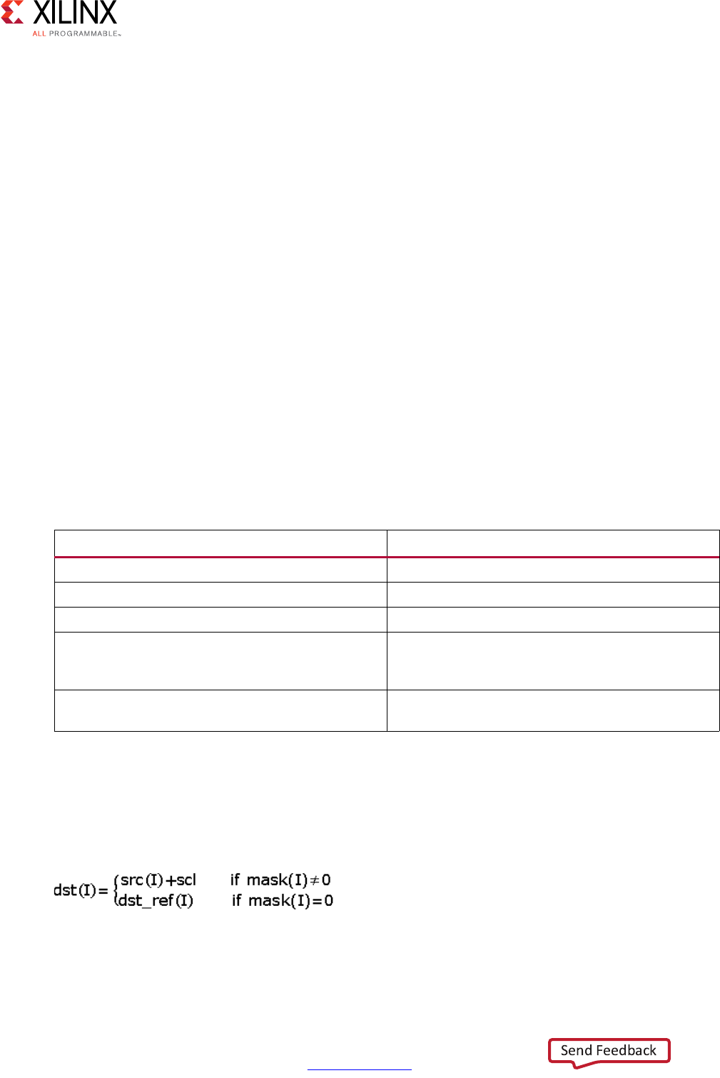
High-Level Synthesis 531
UG902 (v2017.1) April 5, 2017 www.xilinx.com
Chapter 4: High-Level Synthesis Reference Guide
•cv::absdiff
hls::AddS
Synopsis
Without Mask:
template<int ROWS, int COLS, int SRC_T, typename _T, int DST_T>
void hls::AddS (
hls::Mat<ROWS, COLS, SRC_T>& src,
hls::Scalar<HLS_MAT_CN(SRC_T), _T>& scl,
hls::Mat<ROWS, COLS, DST_T>& dst);
With Mask:
template<int ROWS, int COLS, int SRC_T, typename _T, int DST_T>
void hls::AddS (
hls::Mat<ROWS, COLS, SRC_T>& src,
hls::Scalar<HLS_MAT_CN(SRC_T), _T>& scl,
hls::Mat<ROWS, COLS, DST_T>& dst,
hls::Mat<ROWS, COLS, HLS_8UC1>& mask,
hls::Mat<ROWS, COLS, DST_T>& dst_ref);
Parameters
Description
• Computes the per-element sum of an image src and a scalar scl.
• Saves the result in dst.
•If computed with mask:
• Image data must be stored in src (if computed with mask, mask and dst_ref must
have data stored), and the image data of dst must be empty before invoking.
Table 4-20: Parameters
Parameter Description
src Input image
scl Input scalar
dst Output image
mask Operation mask, an 8-bit single channel image
that specifies elements of the dst image to be
computed.
dst_ref Reference image that stores the elements for
output image when mask(I) = 0
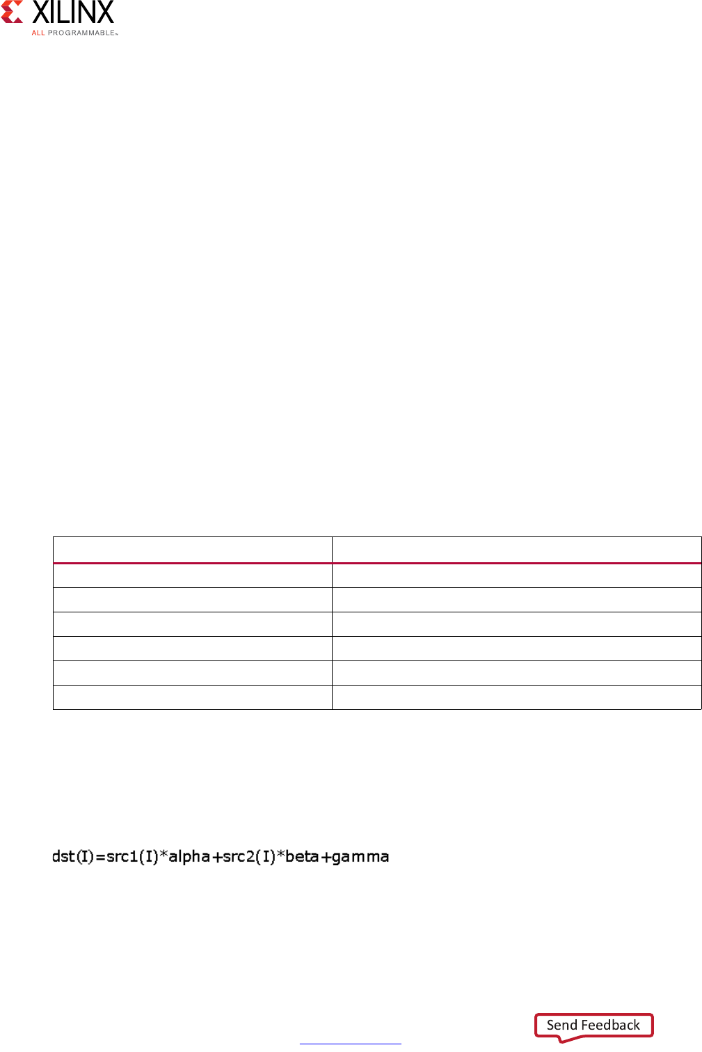
High-Level Synthesis 532
UG902 (v2017.1) April 5, 2017 www.xilinx.com
Chapter 4: High-Level Synthesis Reference Guide
• Invoking this function consumes the data in src (if computed with mask. The data of
mask and dst_ref are also consumed) and fills the image data of dst.
•src and scl must have the same number of channels. dst and dst_ref must have the
same size and number of channels as src. mask must have the same size as the src.
OpenCV Reference
•cvAddS
•cv::add
hls::AddWeighted
Synopsis
template<int ROWS, int COLS, int SRC1_T, int SRC2_T, int DST_T, typename P_T>
void hls::AddWeighted (
hls::Mat<ROWS, COLS, SRC1_T>& src1,
P_T alpha,
hls::Mat<ROWS, COLS, SRC2_T>& src2,
P_T beta,
P_T gamma,
hls::Mat<ROWS, COLS, DST_T>& dst);
Parameters
Description
• Computes the weighted per-element sum of two image src1 and src2.
• Saves the result in dst.
• The weighted sum computes as follows:
• Image data must be stored in src1 and src2.
•The image data of dst must be empty before invoking.
Table 4-21: Parameters
Parameter Description
src1 First input image
alpha Weight for the first image elements
src2 Second input image
beta Weight for the second image elements
gamma Scalar added to each sum
dst Output image

High-Level Synthesis 533
UG902 (v2017.1) April 5, 2017 www.xilinx.com
Chapter 4: High-Level Synthesis Reference Guide
• Invoking this function consumes the data in src1 and src2 and fills the image data of
dst.
• The three parameters (alpha, beta and gamma) must have the same datatypes.
•src1 and src2 must have the same size and number of channels.
•dst must have the same size and number of channels as the inputs.
OpenCV Reference
•cvAddWeighted
• cv::addWeighted
hls::And
Synopsis
Without Mask:
template<int ROWS, int COLS, int SRC1_T, int SRC2_T, int DST_T>
void hls::And (
hls::Mat<ROWS, COLS, SRC1_T>& src1,
hls::Mat<ROWS, COLS, SRC2_T>& src2,
hls::Mat<ROWS, COLS, DST_T>& dst);
With Mask:
template<int ROWS, int COLS, int SRC1_T, int SRC2_T, int DST_T>
void hls::And (
hls::Mat<ROWS, COLS, SRC1_T>& src1,
hls::Mat<ROWS, COLS, SRC2_T>& src2,
hls::Mat<ROWS, COLS, DST_T>& dst,
hls::Mat<ROWS, COLS, HLS_8UC1>& mask,
hls::Mat<ROWS, COLS, DST_T>& dst_ref);
Parameters
Table 4-22: Parameters
Parameter Description
src1 First input image
src2 Second input scalar
dst Output image
mask Operation mask, an 8-bit single channel image that
specifies elements of the dst image to be computed
dst_ref Reference image that stores the elements for output
image when mask(I) = 0
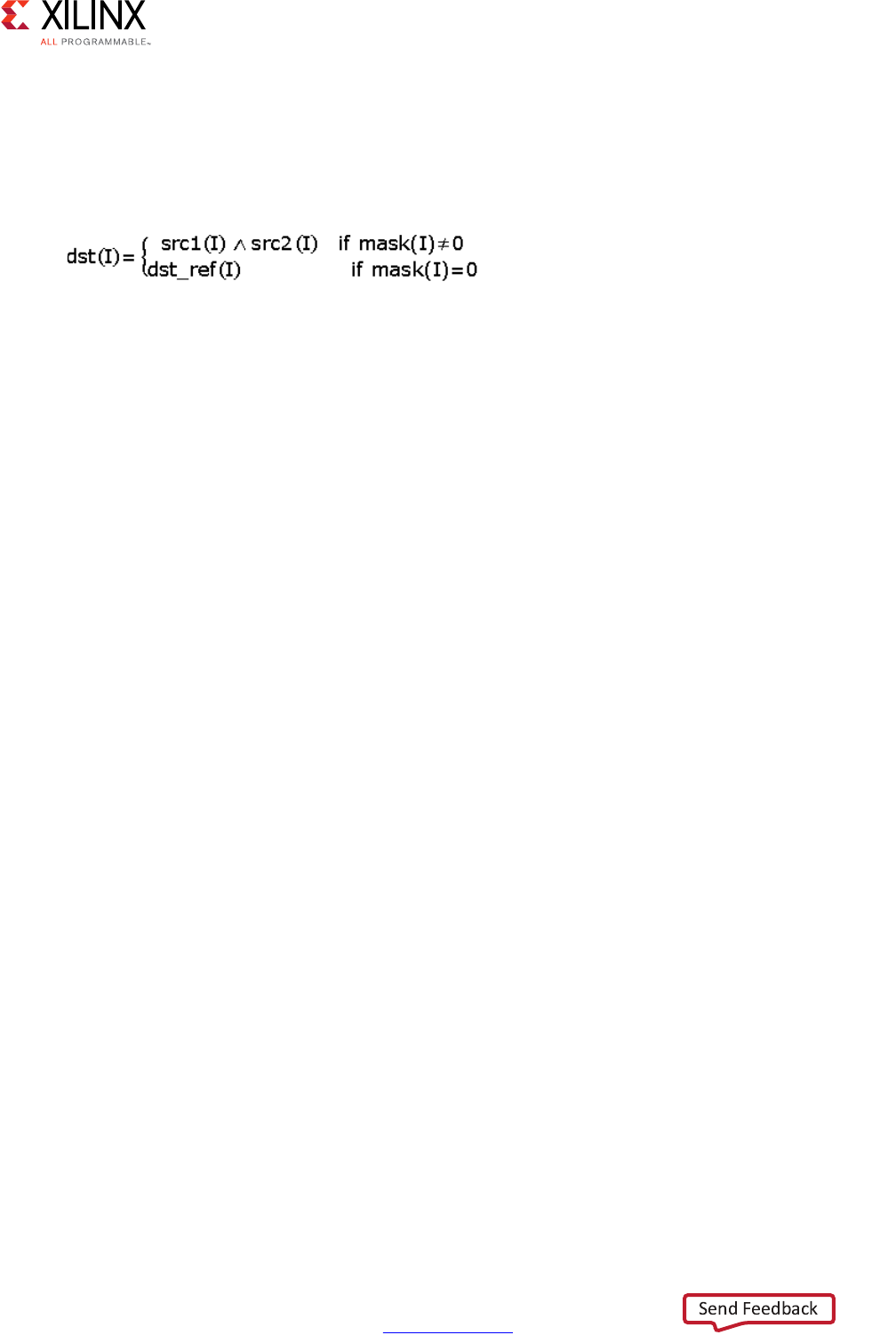
High-Level Synthesis 534
UG902 (v2017.1) April 5, 2017 www.xilinx.com
Chapter 4: High-Level Synthesis Reference Guide
Description
• Calculates the per-element bitwise logical conjunction of two images src1 and src2
• Returns the result as image dst.
•If computed with mask:
• Image data must be stored in src1 and src2.
•The image data of dst must be empty before invoking.
•If computed with mask, mask and dst_ref must have data stored.
• Invoking this function:
°Consumes the data in src1 and src2
Note: If computed with mask, the data of mask and dst_ref are also consumed.
°Fills the image data of dst.
•src1 and src2 must have the same size and number of channels.
•dst and dst_ref must have the same size and number of channels as the inputs.
•mask must have the same size as the inputs.
OpenCV Reference
•cvAnd,
• cv::bitwise_and
hls::Avg
Synopsis
Without Mask:
template<int ROWS, int COLS, int SRC_T, int DST_T>
hls::Scalar<HLS_MAT_CN(DST_T), DST_T> hls::Avg(
hls::Mat<ROWS, COLS, SRC_T>& src);
With Mask:
template<int ROWS, int COLS, int SRC_T, int DST_T>
hls::Scalar<HLS_MAT_CN(DST_T), DST_T> hls::Avg(
hls::Mat<ROWS, COLS, SRC_T>& src,
hls::Mat<ROWS, COLS, HLS_8UC1>& mask);
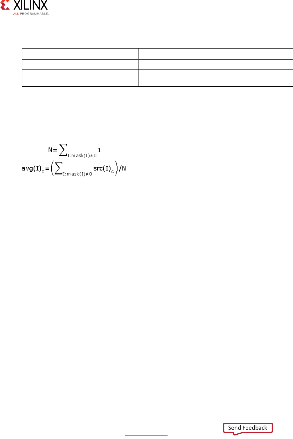
High-Level Synthesis 535
UG902 (v2017.1) April 5, 2017 www.xilinx.com
Chapter 4: High-Level Synthesis Reference Guide
Parameters
Description
• Calculates an average of elements in image src.
• Returns the result in hls::Scalar format.
•If computed with mask:
• Image data must be stored in src.
•If computed with mask, mask must have data stored.
• Invoking this function consumes the data in src.
•If computed with mask, the data of mask is also consumed).
•src and mask must have the same size.
•mask must have non-zero element.
OpenCV Reference
• cvAvg
•cv::mean
hls::AvgSdv
Synopsis
Without Mask:
template<int ROWS, int COLS, int SRC_T, typename _T>
void hls::AvgSdv(
hls::Mat<ROWS, COLS, SRC_T>& src,
hls::Scalar<HLS_MAT_CN(SRC_T), _T>& avg,
hls::Scalar<HLS_MAT_CN(SRC_T), _T>& sdv);
Table 4-23: Parameters
Parameter Description
src Input image
mask Operation mask, an 8-bit single channel image that
specifies elements of the src image to be computed
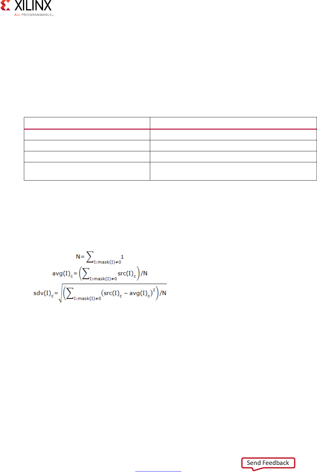
High-Level Synthesis 536
UG902 (v2017.1) April 5, 2017 www.xilinx.com
Chapter 4: High-Level Synthesis Reference Guide
With Mask:
template<int ROWS, int COLS, int SRC_T, typename _T>
void hls::AvgSdv(
hls::Mat<ROWS, COLS, SRC_T>& src,
hls::Scalar<HLS_MAT_CN(SRC_T), _T>& avg,
hls::Scalar<HLS_MAT_CN(SRC_T), _T>& sdv,
hls::Mat<ROWS, COLS, HLS_8UC1>& mask);
Parameters
Description
• Calculates an average of elements in image src.
• Returns the result in hls::Scalar format.
•If computed with mask:
• Image data must be stored in src.
•If computed with mask, mask must have data stored.
• Invoking this function consumes the data in src.
•If computed with mask, the data of mask is also consumed.
•Arguments src and mask must have the same size.
•mask must have a non-zero element.
OpenCV Reference
• cvAvgSdv
•cv::meanStdDev
Table 4-24: Parameters
Parameter Description
src Input image
avg Output scalar of computed mean value
sdv Output scalar of computed standard deviation
mask Operation mask, an 8-bit single channel image that
specifies elements of the src image to be computed
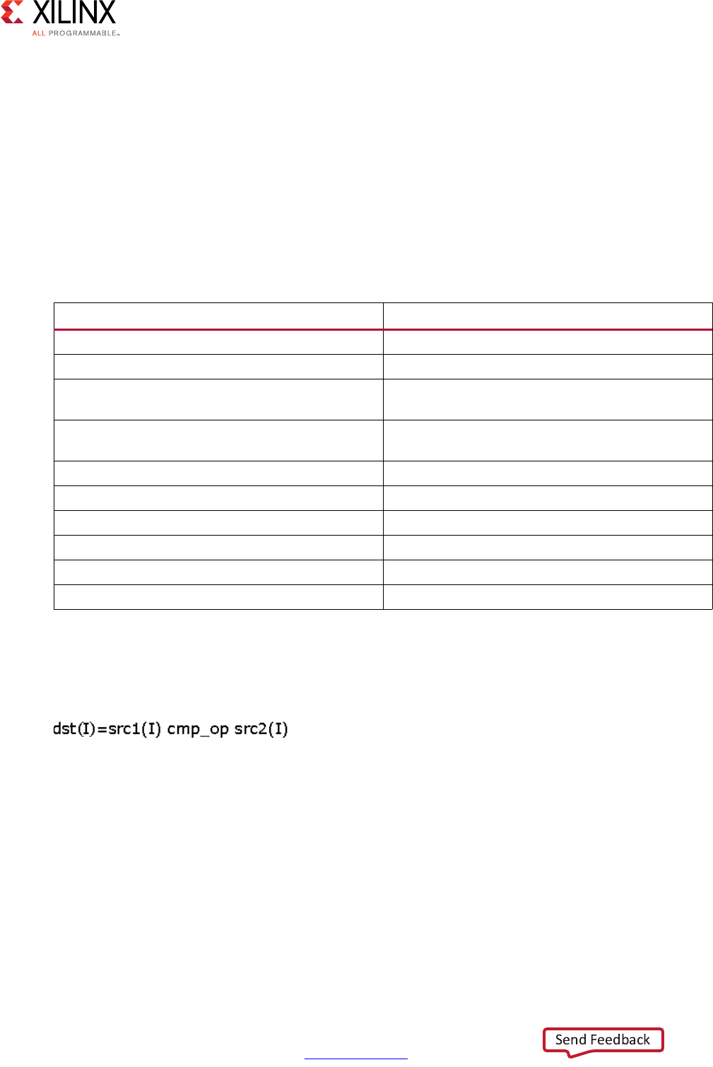
High-Level Synthesis 537
UG902 (v2017.1) April 5, 2017 www.xilinx.com
Chapter 4: High-Level Synthesis Reference Guide
hls::Cmp
Synopsis
template<int ROWS, int COLS, int SRC1_T, int SRC2_T, int DST_T>
void hls::Cmp (
hls::Mat<ROWS, COLS, SRC1_T>& src1,
hls::Mat<ROWS, COLS, SRC2_T>& src2,
hls::Mat<ROWS, COLS, DST_T>& dst,
int cmp_op);
Parameters
Description
• Performs the per-element comparison of two input images src1 and src2.
• Saves the result in dst.
• If the comparison result is true, the corresponding element of dst is set to 255.
Otherwise, it is set to 0.
• Image data must be stored in src1 and src2.
•The image data of dst must be empty before invoking.
• Invoking this function consumes the data in src1 and src2 and fills the image data of
dst.
•src1 and src2 must have the same size and number of channels.
•dst must have the same size and number of channels as the inputs.
Table 4-25: Parameters
Parameter Description
src1 Returns first input image
src2 Returns second input image
dst Returns the output 8returnsbit single channel
image
cmp_op Returns the flag specifying the relation between
the elements to be checked
HLS_CMP_EQ Equal to
HLS_CMP_GT Greater than
HLS_CMP_GE Greater or equal
HLS_CMP_LT Less than
HLS_CMP_LE Less or equal
HLS_CMP_NE Not equal
High-Level Synthesis 538
UG902 (v2017.1) April 5, 2017 www.xilinx.com
Chapter 4: High-Level Synthesis Reference Guide
OpenCV Reference
•cvCmp
•cv::compare
hls::CmpS
Synopsis
template<int ROWS, int COLS, int SRC_T, typename P_T, int DST_T>
void hls::CmpS (
hls::Mat<ROWS, COLS, SRC1_T>& src,
P_T value,
hls::Mat<ROWS, COLS, DST_T>& dst,
int cmp_op);
Parameters
Description
• Performs the comparison between the elements of input images src and the input
value and saves the result in dst.
• If the comparison result is true, the corresponding element of dst is set to 255.
Otherwise it is set to 0.
• Image data must be stored in src.
•The image data of dst must be empty before invoking.
• Invoking this function consumes the data in src and fills the image data of dst.
Table 4-26: Parameters
Parameter Description
src Input image
value Input scalar value
dst Output 8-bit single channel image
cmp_op Flag that specifies the relation between the
elements to be checked
HLS_CMP_EQ Equal to
HLS_CMP_GT Greater than
HLS_CMP_GE Greater or equal
HLS_CMP_LT Less than
HLS_CMP_LE Less or equal
HLS_CMP_NE Not equal
High-Level Synthesis 539
UG902 (v2017.1) April 5, 2017 www.xilinx.com
Chapter 4: High-Level Synthesis Reference Guide
•src and dst must have the same size and number of channels.
OpenCV Reference
•cvCmpS
•cv::compare
hls::CornerHarris
Synopsis
template<int blockSize,int Ksize,typename KT,int SRC_T,int DST_T,int ROWS,int COLS>
void CornerHarris(
hls::Mat<ROWS, COLS, SRC_T> &_src,
hls::Mat<ROWS, COLS, DST_T> &_dst,
KT k);
Parameters
Description
• This function implements a Harris edge/corner detector. The horizontal and vertical
derivatives are estimated using a Ksize*Ksize Sobel filter. The local covariance matrix M
of the derivatives is smoothed over a blockSize*blockSize neighborhood of each pixel
(x,y). This function outputs the function.
• Only Ksize=3 or Ksize=5 is supported.
OpenCV Reference
•cvCornerHarris
• cv::cornerHarris
Table 4-27: Parameters
Parameter Description
src Input image
dst Output mask of detected corners
k Harris detector parameter
borderType How borders are handled

High-Level Synthesis 540
UG902 (v2017.1) April 5, 2017 www.xilinx.com
Chapter 4: High-Level Synthesis Reference Guide
hls::CvtColor
Synopsis
template<int code, int ROWS, int COLS, int SRC_T, int DST_T>
void hls::CvtColor (
hls::Mat<ROWS, COLS, SRC_T>& src,
hls::Mat<ROWS, COLS, DST_T>& dst);
Parameters
Description
• Converts a color image from or to a grayscale image. The type of conversion is defined
by the value of code:
°HLS_RGB2GRAY converts a RGB color image to a grayscale image.
°HLS_BGR2GRAY converts a BGR color image to a grayscale image.
°HLS_GRAY2RGB converts a grayscale image to a RGB image.
°HLS_GRAY2BGR converts a grayscale image to BRG color image.
°HLS_RGB2XYZ converts an RGB color image to XYZ color image.
°HLS_BGR2XYZ converts an BRG color image to XYZ color image.
°HLS_XYZ2RGB converts an XYZ color image to RGB color image.
°HLS_XYZ2BGR converts an XYZ color image to BGR color image.
°HLS_RGB2YCrCb converts an RGB color image to YCbCr color image.
°HLS_BGR2YCrCb converts an BRG color image to YCbCr color image.
°HLS_YCrCb2RGB converts an YCbCr color image to RGB color image.
°HLS_YCrCb2BGR converts an YCbCr color image to BGR color image.
°HLS_RGB2HSV converts an RGB color image to HSV color image.
°HLS_BGR2HSV converts an BRG color image to HSV color image.
°HLS_HSV2RGB converts an HSV color image to RGB color image.
°HLS_HSV2BGR converts an HSV color image to BGR color image.
°HLS_RGB2HLS converts an RGB color image to HLS color image.
Table 4-28: Parameters
Parameter Description
src Input image
dst Output image
code Template parameter of type of color conversion

High-Level Synthesis 541
UG902 (v2017.1) April 5, 2017 www.xilinx.com
Chapter 4: High-Level Synthesis Reference Guide
°HLS_BGR2HLS converts an BRG color image to HLS color image.
°HLS_HLS2RGB converts an HLS color image to RGB color image.
°HLS_HLS2BGR converts an HLS color image to BGR color image.
• Image data must be stored in src.
•The image data of dst must be empty before invoking.
• Invoking this function consumes the data in src and fills the image data of dst.
•src and dst must have the same size and required number of channels.
OpenCV Reference
•cvCvtColor
• cv::cvtColor
hls::Dilate
Synopsis
Default:
template<int ROWS, int COLS, int SRC_T, int DST_T>
void hls::Dilate (
hls::Mat<ROWS, COLS, SRC_T>& src,
hls::Mat<ROWS, COLS, DST_T>& dst);
Custom:
template<int ROWS, int COLS, int SRC_T, int DST_T, int K_ROWS, int K_COLS, typename
K_T, int Shape_type, int ITERATIONS>
void hls::Dilate (
hls::Mat<ROWS, COLS, SRC_T>& src,
hls::Mat<ROWS, COLS, DST_T>& dst,
hls::Window<K_ROWS, K_COLS, K_T> & kernel);
High-Level Synthesis 542
UG902 (v2017.1) April 5, 2017 www.xilinx.com
Chapter 4: High-Level Synthesis Reference Guide
Parameters
Description
• Dilates the image src using the specified structuring element constructed within the
kernel.
• Saves the result in dst.
• The dilation determines the shape of a pixel neighborhood over which the maximum is
taken.
• Each channel of image src is processed independently.
• Image data must be stored in src.
•The image data of dst must be empty before invoking.
• Invoking this function consumes the data in src and fills the image data of dst.
•src and dst must have the same size and number of channels.
OpenCV Reference
• cvDilate
• cv::dilate
Table 4-29: Parameters
Parameter Description
src Input image
dst Output image
kernel Rectangle of structuring element used for dilation,
defined by hls::Window class. Position of the
anchor within the element is at (K_ROWS/2,
K_COLS/2). A 3x3 rectangular structuring element
is used by default.
Shape_type Shape of structuring element
HLS_SHAPE_RECT Rectangular structuring element
HLS_SHAPE_CROSS Cross-shaped structuring element, cross point is at
anchor
HLS_SHAPE_ELLIPSE Elliptic structuring element, a filled ellipse
inscribed into the rectangular element
ITERATIONS Number of times dilation is applied
High-Level Synthesis 543
UG902 (v2017.1) April 5, 2017 www.xilinx.com
Chapter 4: High-Level Synthesis Reference Guide
hls::Duplicate
Synopsis
template<int ROWS, int COLS, int SRC_T, int DST_T>
void hls::Duplicate (
hls::Mat<ROWS, COLS, SRC_T>& src,
hls::Mat<ROWS, COLS, DST_T>& dst1,
hls::Mat<ROWS, COLS, DST_T>& dst2);
Parameters
Description
• Copies the input image src to two output images dst1 and dst2, for divergent point
of two datapaths.
• Image data must be stored in src.
•The image data of dst1 and dst2 must be empty before invoking.
• Invoking this function consumes the data in src and fills the image data of dst1 and
dst2.
•src, dst1, and dst2 must have the same size and number of channels.
OpenCV Reference
Not applicable.
hls::EqualizeHist
Synopsis
template<int SRC_T, int DST_T,int ROW, int COL>
void EqualizeHist(
Mat<ROW, COL, SRC_T>&_src,
Mat<ROW, COL, DST_T>&_dst);
Table 4-30: Parameters
Parameter Description
src Input image
dst1 First output image
dst2 Second output image
High-Level Synthesis 544
UG902 (v2017.1) April 5, 2017 www.xilinx.com
Chapter 4: High-Level Synthesis Reference Guide
Parameters
Description
• Computes a histogram of each frame and uses it to normalize the range of the
following frame.
• The delay avoids the use of a frame buffer in the implementation.
• The histogram is stored as static data internal to this function, allowing only one call to
EqualizeHist to be made.
• The input is expected to have type HLS_8UC1.
OpenCV Reference
•cvEqualizeHist
• cv::EqualizeHist
hls::Erode
Synopsis
Default:
template<int ROWS, int COLS, int SRC_T, int DST_T>
void hls::Erode (
hls::Mat<ROWS, COLS, SRC_T>& src,
hls::Mat<ROWS, COLS, DST_T>& dst);
Custom:
template<int Shape_type,int ITERATIONS,int SRC_T, int DST_T,
typename KN_T,int IMG_HEIGHT,int IMG_WIDTH,int K_HEIGHT,int K_WIDTH>
void Erode(
hls::Mat<IMG_HEIGHT, IMG_WIDTH, SRC_T>&_src,
hls::Mat<IMG_HEIGHT, IMG_WIDTH, DST_T>&_dst,
hls::Window<K_HEIGHT,K_WIDTH,KN_T>&_kernel)
{
Table 4-31: Parameters
Parameter Description
src Input image
dst Output image
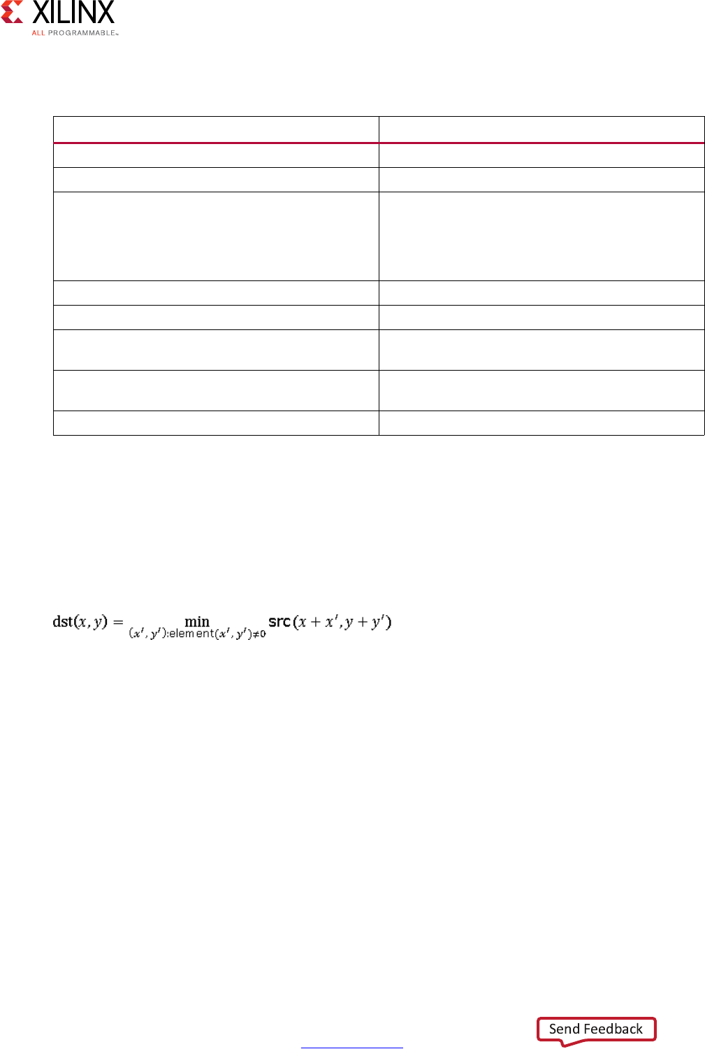
High-Level Synthesis 545
UG902 (v2017.1) April 5, 2017 www.xilinx.com
Chapter 4: High-Level Synthesis Reference Guide
Parameters
Description
• Erodes the image src using the specified structuring element constructed within
kernel.
• Saves the result in dst.
• The erosion determines the shape of a pixel neighborhood over which the maximum is
taken, each channel of image src is processed independently:
• Image data must be stored in src.
•The image data of dst must be empty before invoking.
• Invoking this function consumes the data in src and fills the image data of dst.
•src and dst must have the same size and number of channels.
OpenCV Reference
•cvErode
•cv::erode
Table 4-32: Parameters
Parameter Description
src Input image
dst Output image
kernel Rectangle of structuring element used for dilation,
defined by hls::Window class. Position of the
anchor within the element is at (K_ROWS/2,
K_COLS/2). A 3x3 rectangular structuring element
is used by default.
Shape_type Shape of structuring element
HLS_SHAPE_RECT Rectangular structuring element
HLS_SHAPE_CROSS Cross-shaped structuring element, cross point is at
anchor
HLS_SHAPE_ELLIPSE Elliptic structuring element, a filled ellipse
inscribed into the rectangle element
ITERATIONS Number of times erosion is applied

High-Level Synthesis 546
UG902 (v2017.1) April 5, 2017 www.xilinx.com
Chapter 4: High-Level Synthesis Reference Guide
hls::FASTX
Synopsis
template<int SRC_T,int ROWS,int COLS>
void FASTX(
hls::Mat<ROWS,COLS,SRC_T> &_src,
hls::Mat<ROWS,COLS,HLS_8UC1> &_mask,
int _threshold,
bool _nomax_supression);
template<typename T, int N, int SRC_T,int ROWS,int COLS>
void FASTX(
hls::Mat<ROWS,COLS,SRC_T> &_src,
Point_<T> (&_keypoints)[N],
int _threshold,
bool _nomax_supression);
Parameters
Description
• Implements the FAST corner detector, generating either a mask of corners, or an array
of coordinates.
OpenCV Reference
•cvFAST
•cv::FASTX
Table 4-33: Parameters
Parameter Description
src Input image
mask Output image with value 255 where corners are
detected
keypoints Array of the coordinates of detected corners
threshold FAST detector threshold. If a pixel differs from the
center pixel of the window by more than this
threshold, then it is either a light or a dark pixel.
nomax_supression If true, then enable suppression of non-maximal
edges
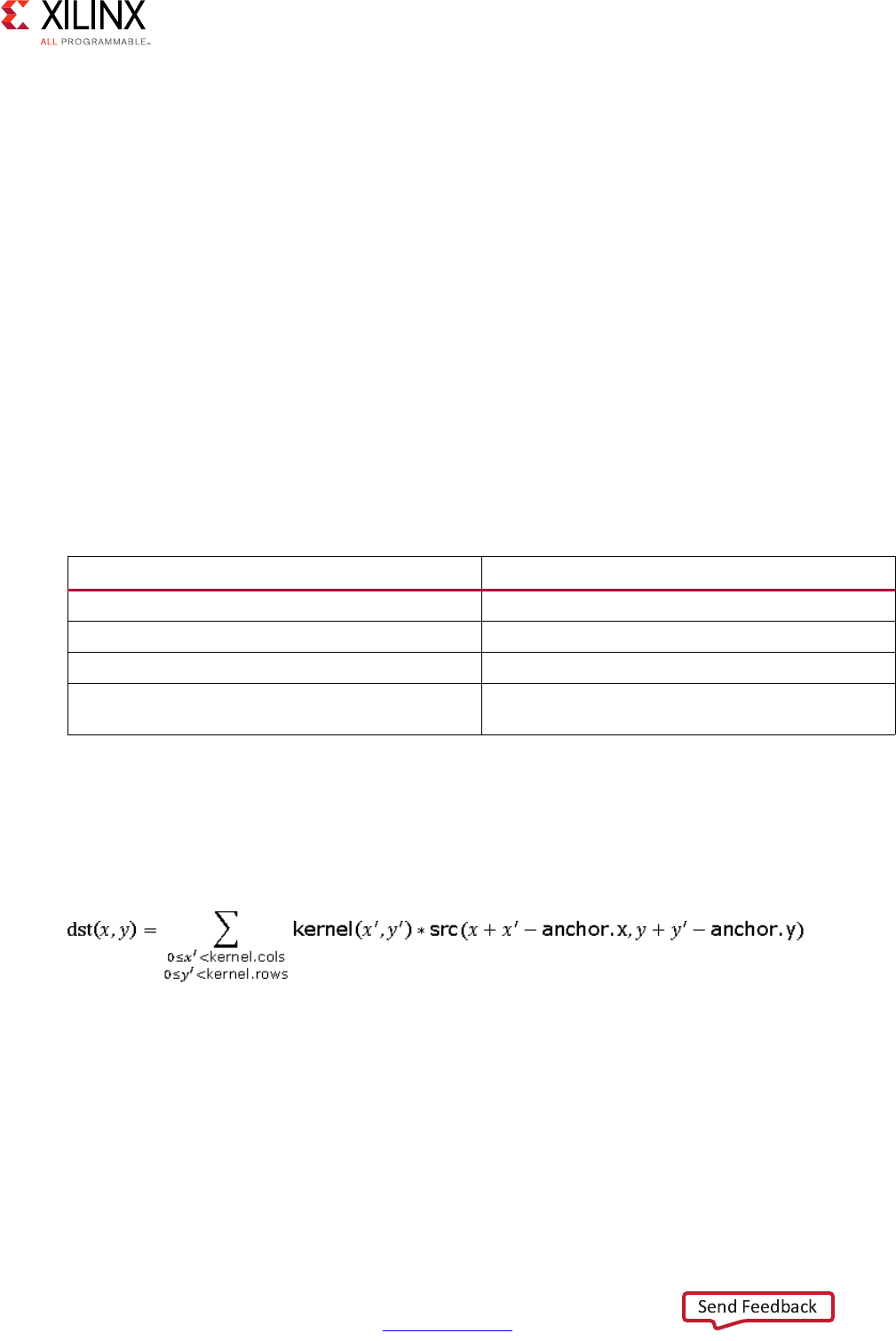
High-Level Synthesis 547
UG902 (v2017.1) April 5, 2017 www.xilinx.com
Chapter 4: High-Level Synthesis Reference Guide
hls::Filter2D
Synopsis
template<typename BORDERMODE, int SRC_T, int DST_T, typename KN_T, typename POINT_T,
int IMG_HEIGHT,int IMG_WIDTH,int K_HEIGHT,int K_WIDTH>
void Filter2D(
Mat<IMG_HEIGHT, IMG_WIDTH, SRC_T>&_src,
Mat<IMG_HEIGHT, IMG_WIDTH, DST_T> &_dst,
Window<K_HEIGHT,K_WIDTH,KN_T>&_kernel,
Point_<POINT_T>anchor)
template<int SRC_T, int DST_T, typename KN_T, typename POINT_T,
int IMG_HEIGHT,int IMG_WIDTH,int K_HEIGHT,int K_WIDTH>
void Filter2D(
Mat<IMG_HEIGHT, IMG_WIDTH, SRC_T>&_src,
Mat<IMG_HEIGHT, IMG_WIDTH, DST_T> &_dst,
Window<K_HEIGHT,K_WIDTH,KN_T>&_kernel,
Point_<POINT_T>anchor);
Parameters
Description
• Applies an arbitrary linear filter to the image src using the specified kernel.
• Saves the result to image dst.
• This function filters the image by computing correlation using kernel:
• Image data must be stored in src.
•The image data of dst must be empty before invoking.
• Invoking this function consumes the data in src and fills the image data of dst.
•src and dst must have the same size and number of channels.
Table 4-34: Parameters
Parameter Description
src Input image
dst Output image
kernel Kernel of 2D filtering, defined by hls::Window class
anchor Anchor of the kernel that indicates that the relative
position of a filtered point within the kernel

High-Level Synthesis 548
UG902 (v2017.1) April 5, 2017 www.xilinx.com
Chapter 4: High-Level Synthesis Reference Guide
OpenCV Reference
The function can be used with or without border modes.
Usage:
hls::Filter2D<3,3,BORDER_CONSTANT>(src,dst)
hls::Filter2D<3,3>(src,dst)
•cv::filter2D
• cvFilter2D (see the note below in the discussion of border modes)
If no border mode is selected, the default mode BORDER_DEFAULT is used.
The selection for the border modes are:
• BORDER_CONSTANT: The input is extended with zeros.
• BORDER_REPLICATE: The input is extended at the boundary with the boundary value.
Given the series of pixels “abcde” the boundary value at the border is completed as
“abcdeeee”.
• BORDER_REFLECT: The input is extended at the boundary with the edge pixel
duplicated. Given the series of pixels “abcde” the boundary value at the border is
completed as “abcdeedc”.
• BORDER_REFLECT_101: The input is extended at the boundary with the edge pixel not
duplicated. Given the series of pixels “abcde” the boundary value at the border is
completed as “abcdedcb”.
• BORDER_DEFAULT: Same as BORDER_REFLECT_101.
Note: For compatibility with OpenCV function cvFilter2D use the BORDER_REPLICATE mode.
hls::FindStereoCorrespondenceBM
Synopsis
template<int WSIZE, int NDISP, int NDISP_UNIT, int ROWS, int COLS, int SRC_T, int
DST_T>
void FindStereoCorrespondenceBM(
Mat<ROWS, COLS, SRC_T>& left,
Mat<ROWS, COLS, SRC_T>& right,
Mat<ROWS, COLS, DST_T>& disp,
StereoBMState<WSIZE, NDISP, NDISP_UNIT>& state)
High-Level Synthesis 549
UG902 (v2017.1) April 5, 2017 www.xilinx.com
Chapter 4: High-Level Synthesis Reference Guide
Parameters
Description
• Computes disparity using the Block Matching algorithm for a rectified stereo pair.
OpenCV Reference
• cvFindStereoCorrespondenceBM
• cv::FindStereoCorrespondenceBM
hls::GaussianBlur
Synopsis
template<int KH,int KW,typename BORDERMODE,int SRC_T,int DST_T,int ROWS,int COLS>
void GaussianBlur(
Mat<ROWS, COLS, SRC_T> &_src,
Mat<ROWS, COLS, DST_T> &_dst,
double sigmaX=0,
double sigmaY=0);
template<int KH,int KW,int SRC_T,int DST_T,int ROWS,int COLS>
void GaussianBlur(
hls::Mat<ROWS, COLS, SRC_T> &_src,
hls::Mat<ROWS, COLS, DST_T> &_dst);
double sigmaX=0,
double sigmaY=0);
Parameters
Description
• Applies a normalized 2D Gaussian Blur filter to the input.
Table 4-35: Parameters
Parameter Description
left Left 8-bit image.
right Right image of the same size and type as the left
image
disp Output disparity map. It has the same size as the
input images.
state Stereo BM state
Table 4-36: Parameters
Parameter Description
src Input image
dst Output image

High-Level Synthesis 550
UG902 (v2017.1) April 5, 2017 www.xilinx.com
Chapter 4: High-Level Synthesis Reference Guide
• The filter coefficients are determined by the KH and KW parameters, which must either
be 3 or 5.
• The 3x3 filter taps are given by:
[1,2,1
2,4,2
1,2,1] * 1/16
• The 5x5 filter taps are given by:
[1, 2, 3, 2, 1,
2, 5, 6, 5, 2,
3, 6, 8, 6, 3,
2, 5, 6, 5, 2,
1, 2, 3, 2, 1]* 1/84
OpenCV Reference
Usage:
hls::GaussianBlur<3,3,BORDER_CONSTANT>(src,dst)
hls::GaussianBlur<3,3>(src,dst)
• cv::GaussianBlur
If no border mode is selected, the default mode BORDER_DEFAULT is used.
The selection for the border modes are:
• BORDER_CONSTANT: The input is extended with zeros.
• BORDER_REPLICATE: The input is extended at the boundary with the boundary value.
Given the series of pixels “abcde” the boundary value the border is completed as
“abcdeeee”.
• BORDER_REFLECT: The input is extended at the boundary with the edge pixel
duplicated. Given the series of pixels “abcde” the boundary value the border is
completed as “abcdeedc”.
• BORDER_REFLECT_101: The input is extended at the boundary with the edge pixel not
duplicated. Given the series of pixels “abcde” the boundary value the border is
completed as “abcdedcb”.
• BORDER_DEFAULT: Same as BORDER_REFLECT_101.
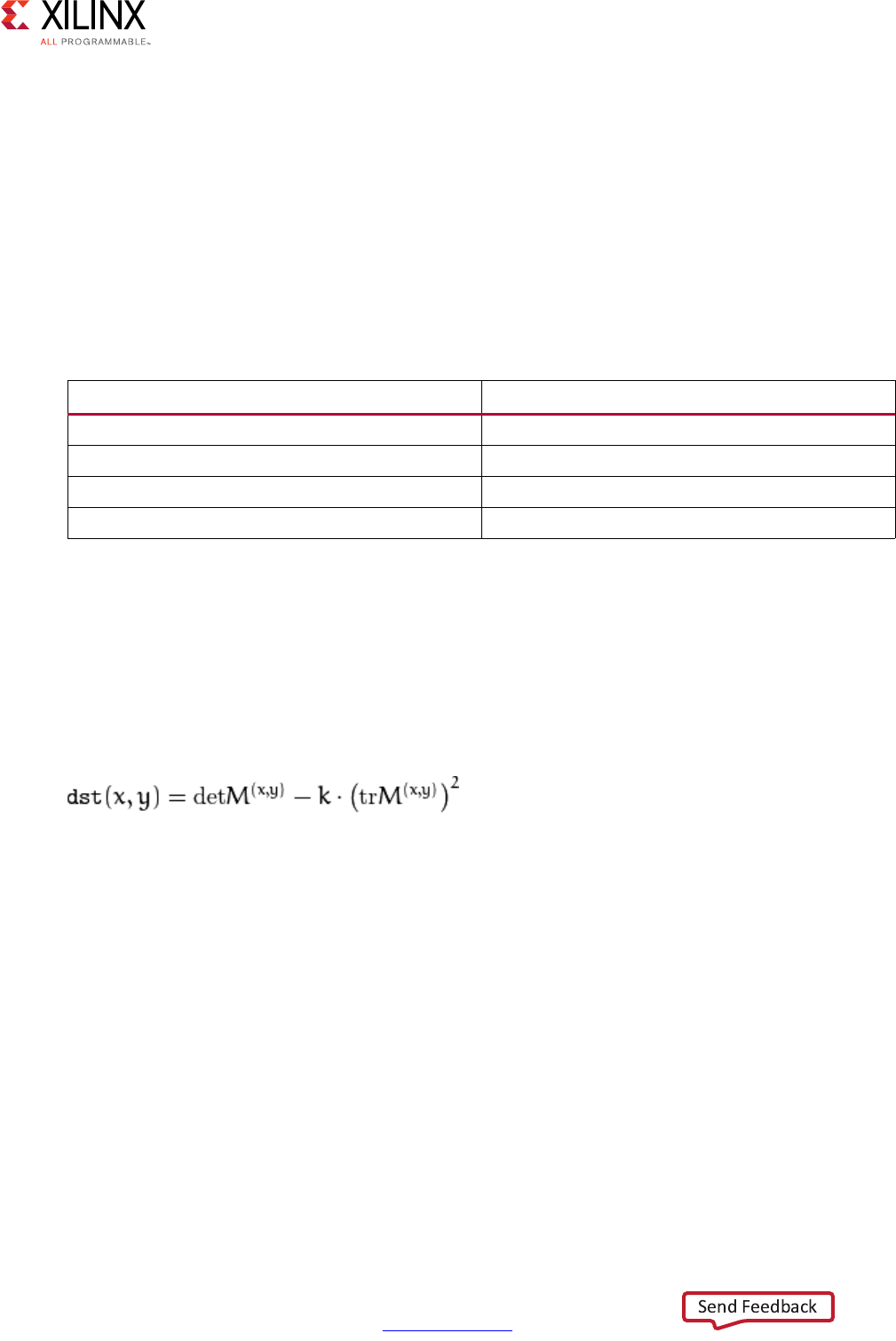
High-Level Synthesis 551
UG902 (v2017.1) April 5, 2017 www.xilinx.com
Chapter 4: High-Level Synthesis Reference Guide
hls::Harris
Synopsis
template<int blockSize,int Ksize,typename KT,int SRC_T,int DST_T,int ROWS,int COLS>
void Harris(
hls::Mat<ROWS, COLS, SRC_T> &_src,
hls::Mat<ROWS, COLS, DST_T> &_dst,
KT k,
int threshold);
Parameters
Description
• This function implements a Harris edge or corner detector.
• The horizontal and vertical derivatives are estimated using a Ksize*Ksize Sobel filter.
• The local covariance matrix M of the derivatives is smoothed over a blockSize*blockSize
neighborhood of each pixel (x,y).
• Points where the function
has a maximum, and is greater than the threshold are marked as corners/edges in the
output image.
• Only Ksize=3 is supported.
OpenCV Reference
•cvCornerHarris
• cv::cornerHarris
hls::HoughLines2
Synopsis
template<typename AT,typename RT>
struct Polar_
Table 4-37: Parameters
Parameter Description
src Input image
dst Output mask of detected corners
k Harris detector parameter
threshold Threshold for maximum finding

High-Level Synthesis 552
UG902 (v2017.1) April 5, 2017 www.xilinx.com
Chapter 4: High-Level Synthesis Reference Guide
AT angle;
RT rho;
};
template<unsigned int theta,unsigned int rho,typename AT,typename RT,int SRC_T,int
ROW,int COL,unsigned int linesMax>
void HoughLines2(
hls::Mat<ROW,COL,SRC_T> &_src,
Polar_<AT,RT> (&_lines)[linesMax],
unsigned int threshold
);
Parameters
Description
• Implements the Hough line transform.
OpenCV Reference
•cvHoughLines2
•cv::HoughLines
hls::Integral
Synopsis
template<int SRC_T, int DST_T, int ROWS,int COLS>
void Integral(
Mat<ROWS, COLS, SRC_T>&_src,
Mat<ROWS+1, COLS+1, DST_T>&_sum);
template<int SRC_T, int DST_T,int DSTSQ_T, ROWS,int COLS>
void Integral(
Mat<ROWS, COLS, SRC_T>&_src,
Mat<ROWS+1, COLS+1, DST_T>&_sum,
Mat<ROWS+1, COLS+1, DSTSQ_T>&_sqsum);
Table 4-38: Parameters
Parameter Description
src Input image
lines Array of parameterized lines, given in polar
coordinates
threshold Number of pixels that must land on a line before it
is returned

High-Level Synthesis 553
UG902 (v2017.1) April 5, 2017 www.xilinx.com
Chapter 4: High-Level Synthesis Reference Guide
Parameters
Description
• Implements the computation of an integral image.
OpenCV Reference
•cvIntegral
•cv::integral
hls::InitUndistortRectifyMap
Synopsis
template< typename CMT, typename RT, typename DT, int ROW, int COL, int MAP1_T, int MAP2_T,
int N>
void InitUndistortRectifyMap(
Window<3,3, CMT> cameraMatrix,
DT (&distCoeffs)[N],
Window<3,3, RT> R,
Window<3,3, CMT> newcameraMatrix,
Mat<ROW, COL, MAP1_T> &map1,
Mat<ROW, COL, MAP2_T> &map2);
template< typename CMT, typename RT, typename DT, int ROW, int COL, int MAP1_T, int MAP2_T,
int N>
void InitUndistortRectifyMapInverse(
Window<3,3, CMT> cameraMatrix,
DT (&distCoeffs)[N],
Window<3,3, ICMT> ir
Mat<ROW, COL, MAP1_T> &map1,
Mat<ROW, COL, MAP2_T> &map2);
Table 4-39: Parameters
Parameter Description
src Input image
sum Sum of pixels in the input image above and to the
left of the pixel
sqsum Sum of the squares of pixels in the input image
above and to the left of the pixel
High-Level Synthesis 554
UG902 (v2017.1) April 5, 2017 www.xilinx.com
Chapter 4: High-Level Synthesis Reference Guide
Parameters
Description
• Generates map1 and map2, based on a set of parameters, where map1 and map2 are
suitable inputs for hls::Remap().
• In general, InitUndistortRectifyMapInverse() is preferred for synthesis, because the
per-frame processing to compute ir is performed outside of the synthesized logic. The
various parameters may be floating point or fixed-point. If fixed-point inputs are used,
then internal coordinate transformations are done with at least the precision given by
ICMT.
• As the coordinate transformations implemented in this function can be hardware
resource intensive, it may be preferable to compute the results of this function offline
and store map1 and map2 in external memory if the input parameters are fixed and
sufficient external memory bandwidth is available.
Limitations
map1 and map2 are only supported as HLS_16SC2. cameraMatrix, and newCameraMatrix,
are normalized in the sense that their form is:
[f_x,0,c_x,
0,f_y,c_y,
0,0,1]
Table 4-40: Parameters
Parameter Description
cameraMatrix Input matrix representing the camera in the old
coordinate system
DT Input distortion coefficients (Generally 4, 5, or 8
distortion coefficients are provided)
R Input rotation matrix
newCameraMatrix Input matrix representing the camera in the new
coordinate system
ir Input transformation matrix, equal to
Invert(newcameraMatrix*R)
map1, map2 Images representing the remapping
High-Level Synthesis 555
UG902 (v2017.1) April 5, 2017 www.xilinx.com
Chapter 4: High-Level Synthesis Reference Guide
R and ir are also normalized with the form:
[a,b,c,
d,e,f,
0,0,1]
OpenCV Reference
• cv::initUndistortRectifyMap
hls::Max
Synopsis
template<int ROWS, int COLS, int SRC1_T, int SRC2_T, int DST_T>
void hls::Max (
hls::Mat<ROWS, COLS, SRC1_T>& src1,
hls::Mat<ROWS, COLS, SRC2_T>& src2,
hls::Mat<ROWS, COLS, DST_T>& dst);
Parameters
Description
• Calculates per-element maximum of two input images src1 and src2 and saves the
result in dst.
• Image data must be stored in src1 and src2.
•The image data of dst must be empty before invoking.
• Invoking this function consumes the data in src1 and src2 and fills the image data of
dst.
•src1 and src2 must have the same size and number of channels. dst must have the
same size and number of channels as the inputs.
OpenCV Reference
•cvMax
•cv::max
Table 4-41: Parameters
Parameter Description
src1 First input image
src2 Second input image
dst Output image

High-Level Synthesis 556
UG902 (v2017.1) April 5, 2017 www.xilinx.com
Chapter 4: High-Level Synthesis Reference Guide
hls::MaxS
Synopsis
template<int ROWS, int COLS, int SRC_T, typename P_T, int DST_T>
void hls::MaxS (
hls::Mat<ROWS, COLS, SRC_T>& src,
P_T value,
hls::Mat<ROWS, COLS, DST_T>& dst);
Parameters
Description
• Calculates the maximum between the elements of input images src and the input value
and saves the result in dst.
• Image data must be stored in src.
•The image data of dst must be empty before invoking.
• Invoking this function consumes the data in src and fills the image data of dst.
•src and dst must have the same size and number of channels.
OpenCV Reference
•cvMaxS
•cv::max
hls::Mean
Synopsis
Without Mask:
template<typename DST_T, int ROWS, int COLS, int SRC_T>
DST_T hls::Mean(
hls::Mat<ROWS, COLS, SRC_T>& src);
Table 4-42: Parameters
Parameter Description
src Input image
value Input scalar value
dst Output image
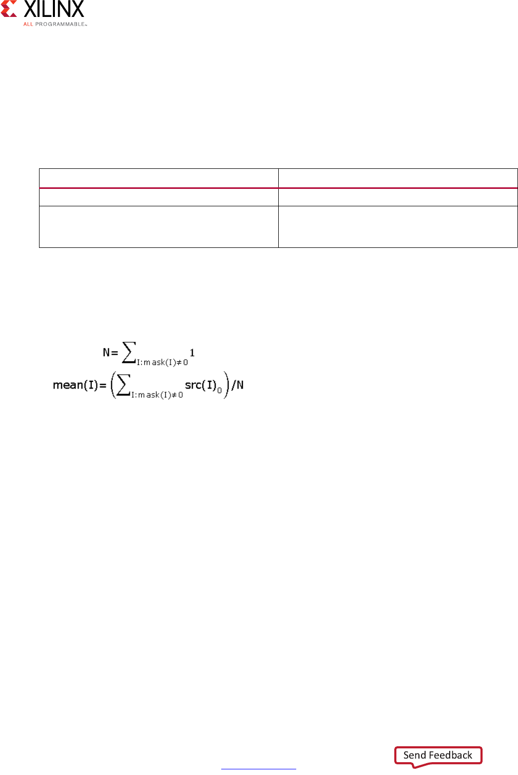
High-Level Synthesis 557
UG902 (v2017.1) April 5, 2017 www.xilinx.com
Chapter 4: High-Level Synthesis Reference Guide
With Mask:
template<typename DST_T, int ROWS, int COLS, int SRC_T>
DST_T hls::Mean(
hls::Mat<ROWS, COLS, SRC_T>& src,
hls::Mat<ROWS, COLS, HLS_8UC1>& mask);
Parameters
Description
• Calculates an average of elements in image src, and return the value of first channel of
result scalar.
•If computed with mask:
• Image data must be stored in src (if computed with mask, mask must have data
stored).
• Invoking this function consumes the data in src (if computes with mask. The data of
mask is also consumed).
•src and mask must have the same size. mask must have non-zero element.
OpenCV Reference
•cvMean
•cv::mean
Table 4-43: Parameters
Parameter Description
src Input image
mask Operation mask, an 8-bit single channel image
that specifies elements of the src image to be
computed

High-Level Synthesis 558
UG902 (v2017.1) April 5, 2017 www.xilinx.com
Chapter 4: High-Level Synthesis Reference Guide
hls::Merge
Synopsis
Input of two single-channel images:
template<int ROWS, int COLS, int SRC_T, int DST_T>
void hls::Merge (
hls::Mat<ROWS, COLS, SRC_T>& src0,
hls::Mat<ROWS, COLS, SRC_T>& src1,
hls::Mat<ROWS, COLS, DST_T>& dst);
Input of three single-channel images:
template<int ROWS, int COLS, int SRC_T, int DST_T>
void hls::Merge (
hls::Mat<ROWS, COLS, SRC_T>& src0,
hls::Mat<ROWS, COLS, SRC_T>& src1,
hls::Mat<ROWS, COLS, SRC_T>& src2,
hls::Mat<ROWS, COLS, DST_T>& dst);
Input of four single-channel images:
template<int ROWS, int COLS, int SRC_T, int DST_T>
void hls::Merge (
hls::Mat<ROWS, COLS, SRC_T>& src0,
hls::Mat<ROWS, COLS, SRC_T>& src1,
hls::Mat<ROWS, COLS, SRC_T>& src2,
hls::Mat<ROWS, COLS, SRC_T>& src3,
hls::Mat<ROWS, COLS, DST_T>& dst);
Parameters
Table 4-44: Parameters
Parameter Description
src0 First single-channel input image
src1 Second single channel input image
src2 Third single channel input image
src3 Fourth single channel input image
dst Output multichannel image
High-Level Synthesis 559
UG902 (v2017.1) April 5, 2017 www.xilinx.com
Chapter 4: High-Level Synthesis Reference Guide
Description
• Composes a multichannel image dst from several single-channel images.
• Image data must be stored in input images.
•The image data of dst must be empty before invoking.
• Invoking this function consumes the data in inputs and fills the image data of dst.
• Input images must have the same size and be single-channel. dst must have the same
size as the inputs, the number of channels of dst must equal to the number of input
images.
OpenCV Reference
•cvMerge
•cv::merge
hls::Min
Synopsis
template<int ROWS, int COLS, int SRC1_T, int SRC2_T, int DST_T>
void hls::Min (
hls::Mat<ROWS, COLS, SRC1_T>& src1,
hls::Mat<ROWS, COLS, SRC2_T>& src2,
hls::Mat<ROWS, COLS, DST_T>& dst);
Parameters
Description
• Calculates per-element minimum of two input images src1 and src2 and saves the
result in dst.
• Image data must be stored in src1 and src2.
•The image data of dst must be empty before invoking.
• Invoking this function consumes the data in src1 and src2 and fills the image data of
dst.
•src1 and src2 must have the same size and number of channels.
•dst must have the same size and number of channels as the inputs.
Table 4-45: Parameters
Parameter Description
src1 First input image
src2 Second input image
dst Output image
High-Level Synthesis 560
UG902 (v2017.1) April 5, 2017 www.xilinx.com
Chapter 4: High-Level Synthesis Reference Guide
OpenCV Reference
• cvMin
•cv::min
hls::MinMaxLoc
Synopsis
Without Mask:
template<int ROWS, int COLS, int SRC_T, typename P_T>
void hls::MinMaxLoc (
hls::Mat<ROWS, COLS, SRC_T>& src,
P_T* min_val,
P_T* max_val,
hls::Point& min_loc,
hls::Point& max_loc);
With Mask:
template<int ROWS, int COLS, int SRC_T, typename P_T>
void hls::MinMaxLoc (
hls::Mat<ROWS, COLS, SRC_T>& src,
P_T* min_val,
P_T* max_val,
hls::Point& min_loc,
hls::Point& max_loc,
hls::Mat<ROWS, COLS, HLS_8UC1>& mask);
Parameters
Description
• Finds the global minimum and maximum and their locations in input image src.
• Image data must be stored in src (if computed with mask, mask must have data
stored).
Table 4-46: Parameters
Parameter Description
src Input image
min_val Pointer to the output minimum value
max_val Pointer to the output maximum value
min_loc Output point of minimum location in input image
max_loc Output point of maximum location in input image
mask Operation mask, an 8-bit single channel image
that specifies elements of the src image to be
found
High-Level Synthesis 561
UG902 (v2017.1) April 5, 2017 www.xilinx.com
Chapter 4: High-Level Synthesis Reference Guide
• Invoking this function consumes the data in src (if computed with mask. The data of
mask is also consumed).
• min_val and max_val must have the save data type. src and mask must have the same
size.
OpenCV Reference
• cvMinMaxLoc
• cv::minMaxLoc
hls::MinS
Synopsis
template<int ROWS, int COLS, int SRC_T, typename P_T, int DST_T>
void hls::MinS (
hls::Mat<ROWS, COLS, SRC_T>& src,
P_T value,
hls::Mat<ROWS, COLS, DST_T>& dst);
Parameters
Description
• Calculates the minimum between the elements of input images src and the input value
and saves the result in dst.
• Image data must be stored in src.
•The image data of dst must be empty before invoking.
• Invoking this function consumes the data in src and fills the image data of dst.
•src and dst must have the same size and number of channels.
OpenCV Reference
• cvMinS
•cv::min
Table 4-47: Parameters
Parameter Description
src Input image
value Input scalar value
dst Output image
High-Level Synthesis 562
UG902 (v2017.1) April 5, 2017 www.xilinx.com
Chapter 4: High-Level Synthesis Reference Guide
hls::Mul
Synopsis
template<int ROWS, int COLS, int SRC1_T, int SRC2_T, int DST_T, typename P_T>
void hls::Mul (
hls::Mat<ROWS, COLS, SRC1_T>& src1,
hls::Mat<ROWS, COLS, SRC2_T>& src2,
hls::Mat<ROWS, COLS, DST_T>& dst,
P_T scale=1);
Parameters
Description
• Calculates the per-element product of two input images src1 and src2.
• Saves the result in image dst. An optional scaling factor scale can be used.
• Image data must be stored in src1 and src2.
•The image data of dst must be empty before invoking.
• Invoking this function consumes the data in src1 and src2 and fills the image data of
dst.
•src1 and src2 must have the same size and number of channels.
•dst must have the same size and number of channels as the inputs.
OpenCV Reference
•cvMul
•cv::multiply
Table 4-48: Parameters
Parameter Description
src1 First input image
src2 Second input image
dst Output image
scale Optional scale factor
High-Level Synthesis 563
UG902 (v2017.1) April 5, 2017 www.xilinx.com
Chapter 4: High-Level Synthesis Reference Guide
hls::Not
Synopsis
template<int ROWS, int COLS, int SRC_T, int DST_T>
void hls::Not (
hls::Mat<ROWS, COLS, SRC_T>& src,
hls::Mat<ROWS, COLS, DST_T>& dst);
Parameters
Description
• Performs per-element bitwise inversion of image src.
• Outputs the result as image dst.
• Image data must be stored in src.
•The image data of dst must be empty before invoking.
• Invoking this function consumes the data in src and fills the image data of dst.
•src and dst must have the same size and number of channels.
OpenCV Reference
•cvNot
• cv::bitwise_not
hls::PaintMask
Synopsis
template<int SRC_T,int MASK_T,int ROWS,int COLS>
void PaintMask(
hls::Mat<ROWS,COLS,SRC_T> &_src,
hls::Mat<ROWS,COLS,MASK_T> &_mask,
hls::Mat<ROWS,COLS,SRC_T> &_dst,
hls::Scalar<HLS_MAT_CN(SRC_T),HLS_TNAME(SRC_T)> _color);
Table 4-49: Parameters
Parameter Description
src Input image
dst Output image
High-Level Synthesis 564
UG902 (v2017.1) April 5, 2017 www.xilinx.com
Chapter 4: High-Level Synthesis Reference Guide
Parameters
Description
• Each pixel of the destination image is either set to color (if mask is not zero) or the
corresponding pixel from the input image.
•src, mask, and dst must all be the same size.
hls::PyrDown
Synopsis
template<int SRC_T,int DST_T,int ROWS,int COLS, int DROWS, int DCOLS>
void PyrDown(
Mat<ROWS, COLS, SRC_T> &_src,
Mat<DROWS, DCOLS, DST_T> &_dst)
Parameters
Description
• Blurs an image by performing the Gaussian pyramid construction and then downsizes
the image by a factor of 2.
• First, this function convolves the source image with the following kernel:
[1, 4, 6, 4, 1,
4, 16, 24, 16, 2,
6, 24, 36, 24, 6,
4, 16, 24, 16, 2,
1, 4, 6, 4, 1]* 1/256
Table 4-50: Parameters
Parameter Description
src Input image
mask Input mask
dst Output image
color Color for marking
Table 4-51: Parameters
Parameter Description
src Input image
dst Output image
High-Level Synthesis 565
UG902 (v2017.1) April 5, 2017 www.xilinx.com
Chapter 4: High-Level Synthesis Reference Guide
• Then, this function downsamples the image by rejecting even rows and columns.
OpenCV Reference
•cvPyrDown
•cv::pyrDown
hls::PyrUp
Synopsis
template<int SRC_T,int DST_T,int ROWS,int COLS, int DROWS, int DCOLS>
void PyrUp(
Mat<ROWS, COLS, SRC_T> &_src,
Mat<DROWS, DCOLS, DST_T> &_dst)
Parameters
Description
• Upsamples the image by a factor of 2 and then blurs it.
• The function performs the upsampling step of the Gaussian pyramid construction,
though it can actually be used to construct the Laplacian pyramid.
• First, this function upsamples the source image by injecting even zero rows and
columns.
• Then, this function convolves the result with the following kernel (same as in pyrDown()
but multiplied by 4).
[1, 4, 6, 4, 1,
4, 16, 24, 16, 4,
6, 24, 36, 24, 6,
4, 16, 24, 16, 4,
1, 4, 6, 4, 1]* 1/64
Table 4-52: Parameters
Parameter Description
src Input image
dst Output image
High-Level Synthesis 566
UG902 (v2017.1) April 5, 2017 www.xilinx.com
Chapter 4: High-Level Synthesis Reference Guide
OpenCV Reference
•cvPyrUp
•cv::pyrup
hls::Range
Synopsis
template<int ROWS, int COLS, int SRC_T, int DST_T, typename P_T>
void hls::Range (
hls::Mat<ROWS, COLS, SRC_T>& src,
hls::Mat<ROWS, COLS, DST_T>& dst,
P_T start,
P_T end);
Parameters
Description
• Sets all value in image src by the following rule and return the result as image dst.
• Image data must be stored in src.
•The image data of dst must be empty before invoking.
• Invoking this function consumes the data in src and fills the image data of dst.
•src and dst must have the same size and be single-channel images.
OpenCV Reference
•cvRange
Table 4-53: Parameters
Parameter Description
src Input single-channel image
dst Output single-channel image
start Left boundary value of the range
end Right boundary value of the range
High-Level Synthesis 567
UG902 (v2017.1) April 5, 2017 www.xilinx.com
Chapter 4: High-Level Synthesis Reference Guide
hls::Remap
Synopsis
template <int WIN_ROW, int ROW, int COL, int SRC_T, int DST_T, int MAP1_T, int
MAP2_T>
void Remap(
hls::Mat<ROW, COL, SRC_T> &src,
hls::Mat<ROW, COL, DST_T> &dst,
hls::Mat<ROW, COL, MAP1_T> &map1,
hls::Mat<ROW, COL, MAP2_T> &map2);
Parameters
Description
• Remaps the source image src to the destination image dst according to the given
remapping. For each pixel in the output image, the coordinates of an input pixel are
specified by map1 and map2.
• This function is designed for streaming operation for cameras with small vertical
disparity. It contains an internal linebuffer to enable the remapping that contains
WIN_ROW rows of the input image. If the row r_i of an input pixel corresponding to an
output pixel at row r_o is not in the range [r_o-(WIN_ROW/2-1], r_o+(WIN_ROW/2-1)
then the output is black.
• In addition, because of the architecture of the line buffer, the function uses fewer
resources if WIN_ROW and COL are powers of 2.
OpenCV Reference
•cvRemap
Table 4-54: Parameters
Parameter Description
src Input image
dst Output image
•map1
•map2
Remapping

High-Level Synthesis 568
UG902 (v2017.1) April 5, 2017 www.xilinx.com
Chapter 4: High-Level Synthesis Reference Guide
hls::Reduce
Synopsis
template<typename INTER_SUM_T, int ROWS, int COLS, int SRC_T, int DST_ROWS, int
DST_COLS, int DST_T>
void hls::Reduce (
hls::Mat<ROWS, COLS, SRC_T>& src,
hls::Mat<DST_ROWS, DST_COLS, DST_T>& dst,
int dim,
int reduce_op=HLS_REDUCE_SUM);
Parameters
Description
• Reduces 2D image src along dimension dim to a vector dst.
• Image data must be stored in src.
•The data of dst must be empty before invoking.
• Invoking this function consumes the data in src and fills the image data of dst.
OpenCV Reference
• cvReduce,
•cv::reduce
Table 4-55: Parameters
Parameter Description
src Input matrix
dst Output vector
dim Dimension index along which the matrix is reduced. 0 means that the
matrix is reduced to a single row. 1 means that the matrix is reduced
to a single column.
reduce_op Reduction operation:
• HLS_REDUCE_SUM: Output is the sum of all of the matrix
rows/columns
• HLS_REDUCE_AVG: Output is the mean vector of all of the matrix
rows/columns
• HLS_REDUCE_MAX: Output is the maximum (column/row-wise) of
all of the matrix rows/columns
• HLS_REDUCE_MIN: Output is the minimum (column/row-wise) of
all of the matrix rows/columns

High-Level Synthesis 569
UG902 (v2017.1) April 5, 2017 www.xilinx.com
Chapter 4: High-Level Synthesis Reference Guide
hls::Resize
Synopsis
template<int SRC_T, int ROWS,int COLS,int DROWS,int DCOLS>
void Resize (
Mat<ROWS, COLS, SRC_T> &_src,
Mat<DROWS, DCOLS, SRC_T> &_dst);
Parameters
Description
• Resizes the input image to the size of the output image using bilinear interpolation.
OpenCV Reference
•cvResize
•cv::resize
hls::Set
Synopsis
Sets src image:
template<int ROWS, int COLS, int SRC_T, typename _T, int DST_T>
void hls::Set (
hls::Mat<ROWS, COLS, SRC_T>& src,
hls::Scalar<HLS_MAT_CN(DST_T), _T> scl,
hls::Mat<ROWS, COLS, DST_T>& dst);
Generates dst image:
template<int ROWS, int COLS, typename _T, int DST_T>
void hls::Set (
hls::Scalar<HLS_MAT_CN(DST_T), _T> scl,
hls::Mat<ROWS, COLS, DST_T>& dst);
Table 4-56: Parameters
Parameter Description
src Input image
dst Output image
High-Level Synthesis 570
UG902 (v2017.1) April 5, 2017 www.xilinx.com
Chapter 4: High-Level Synthesis Reference Guide
Parameters
Description
• Sets elements in image src to a given scalar value scl.
• Saves the result as image dst.
• Generates a dst image with all element has scalar value scl if no input image.
• Image data must be stored in src.
•The image data of dst must be empty before invoking.
• Invoking this function consumes the data in src and fills the image data of dst.
•src and scl must have the same number of channels.
•dst must have the same size and number of channels as src.
OpenCV Reference
•cvSet
hls::Scale
Synopsis
template<int ROWS, int COLS, int SRC_T, int DST_T, typename P_T>
void hls::Scale (
hls::Mat<ROWS, COLS, SRC_T>& src,
hls::Mat<ROWS, COLS, DST_T>& dst,
P_T scale=1.0,
P_T shift=0.0);
Parameters
Table 4-57: Parameters
Parameter Description
src Input image
scl Scale value to be set
dst Output image
Table 4-58: Parameters
Parameter Description
src Input image
dst Output image
scale Value of scale factor
shift Value added to the scaled elements
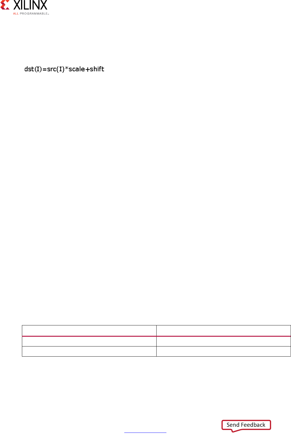
High-Level Synthesis 571
UG902 (v2017.1) April 5, 2017 www.xilinx.com
Chapter 4: High-Level Synthesis Reference Guide
Description
• Converts an input image src with optional linear transformation.
• Saves the result as image dst.
• Image data must be stored in src.
•The image data of dst must be empty before invoking.
• Invoking this function consumes the data in src and fills the image data of dst.
•src and dst must have the same size and number of channels. scale and shift must
have the same data types.
OpenCV Reference
•cvScale
• cvConvertScale
hls::Sobel
Synopsis
template<int XORDER, int YORDER, int SIZE, typename BORDERMODE, int SRC_T, int DST_T,
int ROWS,int COLS,int DROWS,int DCOLS>
void Sobel (
Mat<ROWS, COLS, SRC_T>&_src,
Mat<DROWS, DCOLS, DST_T>&_dst)
template<int XORDER, int YORDER, int SIZE, int SRC_T, int DST_T, int ROWS,int
COLS,int DROWS,int DCOLS>
void Sobel (
Mat<ROWS, COLS, SRC_T>&_src,
Mat<DROWS, DCOLS, DST_T>&_dst)
Parameters
Table 4-59: Parameters
Parameter Description
src Input image
dst Output image

High-Level Synthesis 572
UG902 (v2017.1) April 5, 2017 www.xilinx.com
Chapter 4: High-Level Synthesis Reference Guide
Description
• Computes a horizontal or vertical Sobel filter, returning an estimate of the horizontal or
vertical derivative, using a filter such as:
[-1,0,1
-2,0,2,
-1,0,1]
• SIZE=3, 5, or 7 is supported. This is the same as the equivalent OpenCV function.
• Only XORDER=1 and YORDER=0 (corresponding to horizontal derivative) or XORDER=0
and YORDER=1 (corresponding to a vertical derivative) are supported.
OpenCV Reference
The function can be used with or without border modes.
Usage:
hls::Sobel<1,0,3,BORDER_CONSTANT>(src,dst)
hls::Sobel<1,0,3>(src,dst)
•cv::Sobel
• cvSobel (see the note below in the discussion of border modes).
If no border mode is selected, the default mode BORDER_DEFAULT is used.
The selection for the border modes are:
• BORDER_CONSTANT: The input is extended with zeros.
• BORDER_REPLICATE: The input is extended at the boundary with the boundary value.
Given the series of pixels “abcde” the boundary value the border is completed as
“abcdeeee”.
• BORDER_REFLECT: The input is extended at the boundary with the edge pixel
duplicated. Given the series of pixels “abcde” the boundary value the border is
completed as “abcdeedc”
• BORDER_REFLECT_101: The input is extended at the boundary with the edge pixel not
duplicated. Given the series of pixels “abcde” the boundary value the border is
completed as “abcdedcb”.
• BORDER_DEFAULT: Same as BORDER_REFLECT_101.
Note: For compatibility with OpenCV function cvSobel, use the BORDER_REPLICATE mode.
High-Level Synthesis 573
UG902 (v2017.1) April 5, 2017 www.xilinx.com
Chapter 4: High-Level Synthesis Reference Guide
hls::Split
Synopsis
Input image has 2 channels:
template<int ROWS, int COLS, int SRC_T, int DST_T>
void hls::Split (
hls::Mat<ROWS, COLS, SRC_T>& src,
hls::Mat<ROWS, COLS, DST_T>& dst0,
hls::Mat<ROWS, COLS, DST_T>& dst1);
Input image has 3 channels:
template<int ROWS, int COLS, int SRC_T, int DST_T>
void hls::Split (
hls::Mat<ROWS, COLS, SRC_T>& src,
hls::Mat<ROWS, COLS, DST_T>& dst0,
hls::Mat<ROWS, COLS, DST_T>& dst1,
hls::Mat<ROWS, COLS, DST_T>& dst2);
Input image has 4 channels:
template<int ROWS, int COLS, int SRC_T, int DST_T>
void hls::Split (
hls::Mat<ROWS, COLS, SRC_T>& src,
hls::Mat<ROWS, COLS, DST_T>& dst0,
hls::Mat<ROWS, COLS, DST_T>& dst1,
hls::Mat<ROWS, COLS, DST_T>& dst2,
hls::Mat<ROWS, COLS, DST_T>& dst3);
Parameters
Description
• Divides a multichannel image src from several single-channel images.
• Image data must be stored in image src.
• The image data of outputs must be empty before invoking.
• Invoking this function consumes the data in src and fills the image data of outputs.
• Output images must have the same size and be single-channel.
Table 4-60: Parameters
Parameter Description
src Input multichannel image
dst0 First single channel output image
dst1 Second single channel output image
dst2 Third single channel output image
dst3 Fourth single channel output image
High-Level Synthesis 574
UG902 (v2017.1) April 5, 2017 www.xilinx.com
Chapter 4: High-Level Synthesis Reference Guide
•src must have the same size as the outputs.
• The number of channels of src must equal to the number of output images.
OpenCV Reference
• cvSplit
• cv::split
hls::SubRS
Synopsis
Without Mask:
template<int ROWS, int COLS, int SRC_T, typename _T, int DST_T>
void hls::SubRS (
hls::Mat<ROWS, COLS, SRC_T>& src,
hls::Scalar<HLS_MAT_CN(SRC_T), _T>& scl,
hls::Mat<ROWS, COLS, DST_T>& dst);
With Mask:
template<int ROWS, int COLS, int SRC_T, typename _T, int DST_T>
void hls::SubRS (
hls::Mat<ROWS, COLS, SRC_T>& src,
hls::Scalar<HLS_MAT_CN(SRC_T), _T>& scl,
hls::Mat<ROWS, COLS, DST_T>& dst,
hls::Mat<ROWS, COLS, HLS_8UC1>& mask,
hls::Mat<ROWS, COLS, DST_T>& dst_ref);
Parameters
Description
• Computes the differences between scalar value scl and elements of image src.
• Saves the result in dst.
•If computed with mask:
Table 4-61: Parameters
Parameter Description
src Input image
scl Input scalar
dst Output image
mask Operation mask, an 8-bit single channel image that
specifies elements of the dst image to be
computed
dst_ref Reference image that stores the elements for
output image when mask(I) = 0
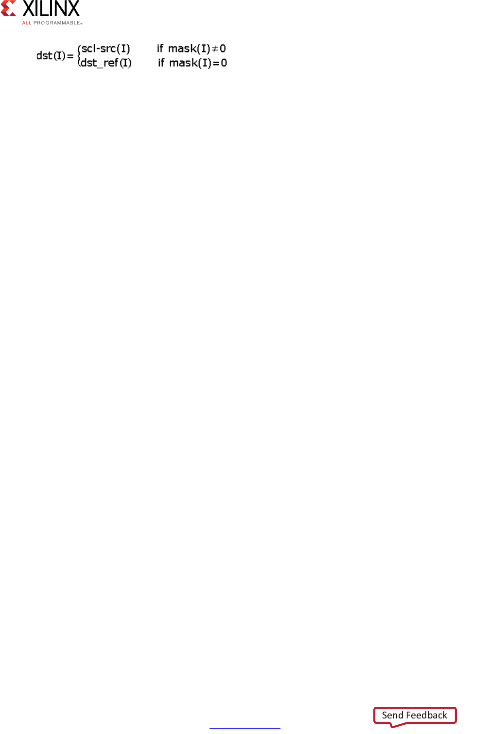
High-Level Synthesis 575
UG902 (v2017.1) April 5, 2017 www.xilinx.com
Chapter 4: High-Level Synthesis Reference Guide
• Image data must be stored in src.
•If computed with mask, mask and dst_ref must have data stored.
•The image data of dst must be empty before invoking.
• Invoking this function consumes the data in src.
•If computed with mask, the data of mask and dst_ref are also consumed and fills the
image data of dst.
• src and scl must have the same number of channels. dst and dst_ref must have the
same size and number of channels as src. mask must have the same size as the src.
OpenCV Reference
•cvSubRS
•cv::subtract
hls::SubS
Synopsis
Without Mask:
template<int ROWS, int COLS, int SRC_T, typename _T, int DST_T>
void hls::SubRS (
hls::Mat<ROWS, COLS, SRC_T>& src,
hls::Scalar<HLS_MAT_CN(SRC_T), _T>& scl,
hls::Mat<ROWS, COLS, DST_T>& dst);
With Mask:
template<int ROWS, int COLS, int SRC_T, typename _T, int DST_T>
void hls::SubRS (
hls::Mat<ROWS, COLS, SRC_T>& src,
hls::Scalar<HLS_MAT_CN(SRC_T), _T>& scl,
hls::Mat<ROWS, COLS, DST_T>& dst,
hls::Mat<ROWS, COLS, HLS_8UC1>& mask,
hls::Mat<ROWS, COLS, DST_T>& dst_ref);
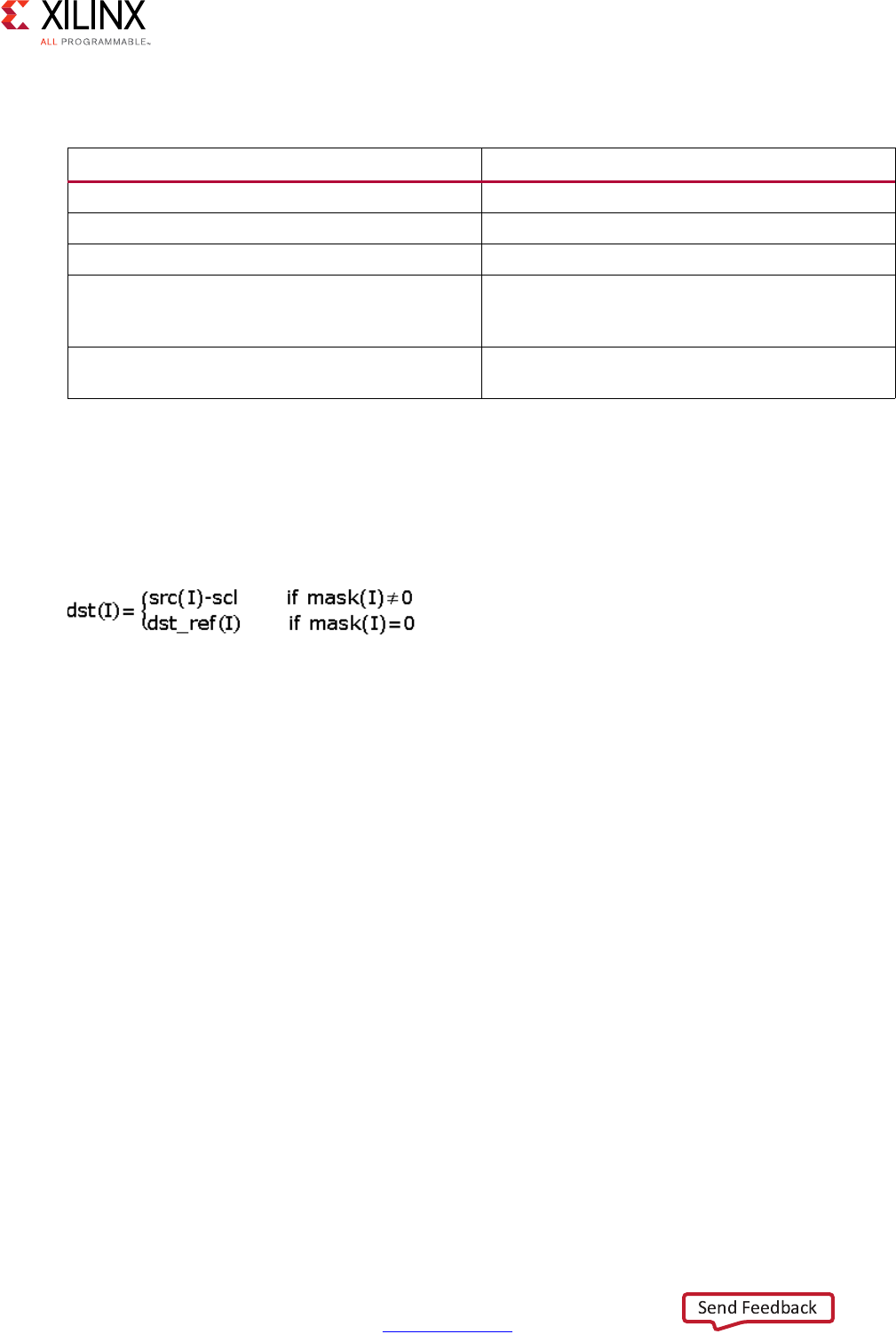
High-Level Synthesis 576
UG902 (v2017.1) April 5, 2017 www.xilinx.com
Chapter 4: High-Level Synthesis Reference Guide
Parameters
Description
• Computes the differences between elements of image src and scalar value scl.
• Saves the result in dst.
If computed with mask:
• Image data must be stored in src.
•If computed with mask, mask and dst_ref must have data stored.
•The image data of dst must be empty before invoking.
• Invoking this function consumes the data in src and fills the image data of dst.
•If computed with mask, the data of mask and dst_ref are also consumed.
• src and scl must have the same number of channels.
•dst and dst_ref must have the same size and number of channels as src
OpenCV Reference
•cvSub
•cv::subtract
hls::Sum
Synopsis
template<typename DST_T, int ROWS, int COLS, int SRC_T>
hls::Scalar<HLS_MAT_CN(SRC_T), DST_T> hls::Sum(
hls::Mat<ROWS, COLS, SRC_T>& src);
Table 4-62: Parameters
Parameter Description
src Input image
scl Input scalar
dst Output image
mask Operation mask, an 8-bit single channel image that
specifies elements of the dst image to be
computed
dst_ref Reference image that stores the elements for
output image when mask(I) = 0
High-Level Synthesis 577
UG902 (v2017.1) April 5, 2017 www.xilinx.com
Chapter 4: High-Level Synthesis Reference Guide
Parameters
Description
• Sums the elements of an image src.
• Returns the result as a scalar value.
• Image data must be stored in src
• Invoking this function consumes the data in src
OpenCV Reference
•cvSum
•cv::sum
hls::Threshold
Synopsis
template<int ROWS, int COLS, int SRC_T, int DST_T, typename P_T>
void hls::Threshold (
hls::Mat<ROWS, COLS, SRC_T>& src,
hls::Mat<ROWS, COLS, DST_T>& dst,
P_T thresh,
P_T maxval,
int thresh_type);
Parameters
Table 4-63: Parameters
Parameter Description
src Input image
Table 4-64: Parameters
Parameter Description
src Input single-channel image
dst Output single-channel image
thresh Threshold value
maxval Maximum value to use with some threshold types
thresh_type Threshold type. See details in description.
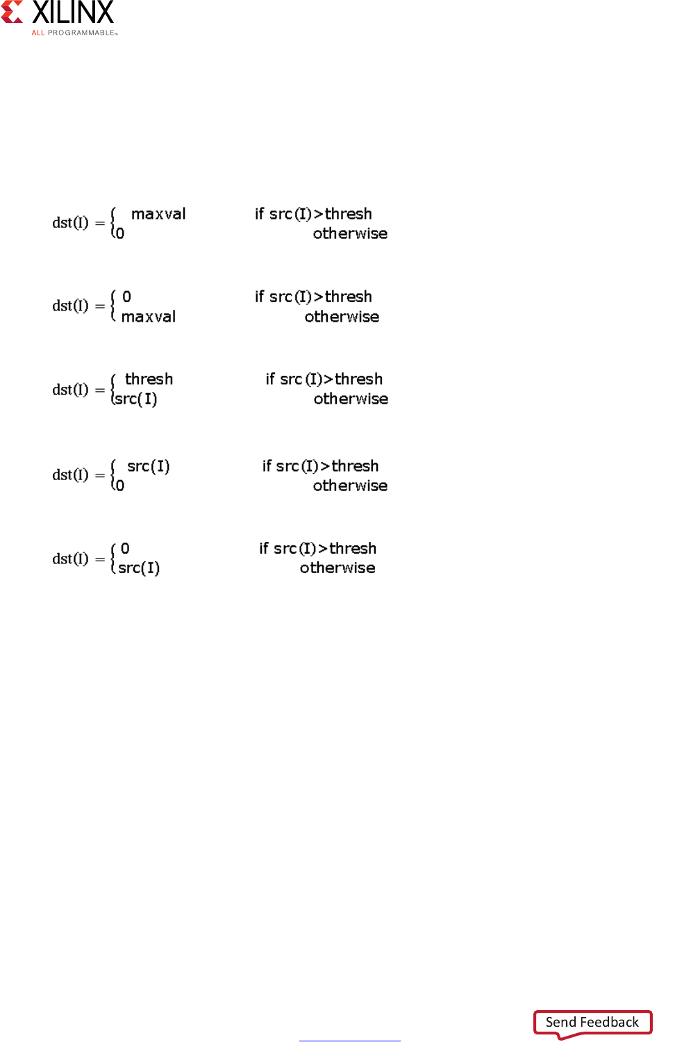
High-Level Synthesis 578
UG902 (v2017.1) April 5, 2017 www.xilinx.com
Chapter 4: High-Level Synthesis Reference Guide
Description
Performs a fixed-level threshold to each element in a single-channel image src and return
the result as a single-channel image dst. The thresholding type supported by this function
are determined by thresh_type:
HLS_THRESH_BINARY
HLS_THRESH_BINARY_INV
HLS_THRESH_TRUNC
HLS_THRESH_TOZERO
HLS_THRESH_TOZERO_INV
• Image data must be stored in (if computed with src).
•The image data of dst must be empty before invoking.
• Invoking this function consumes the data in src and fills the image data of dst.
•src and dst must have the same size and be single-channel images. thresh and maxval
must have the same data types.
OpenCV Reference
• cvThreshold
• cv::threshold
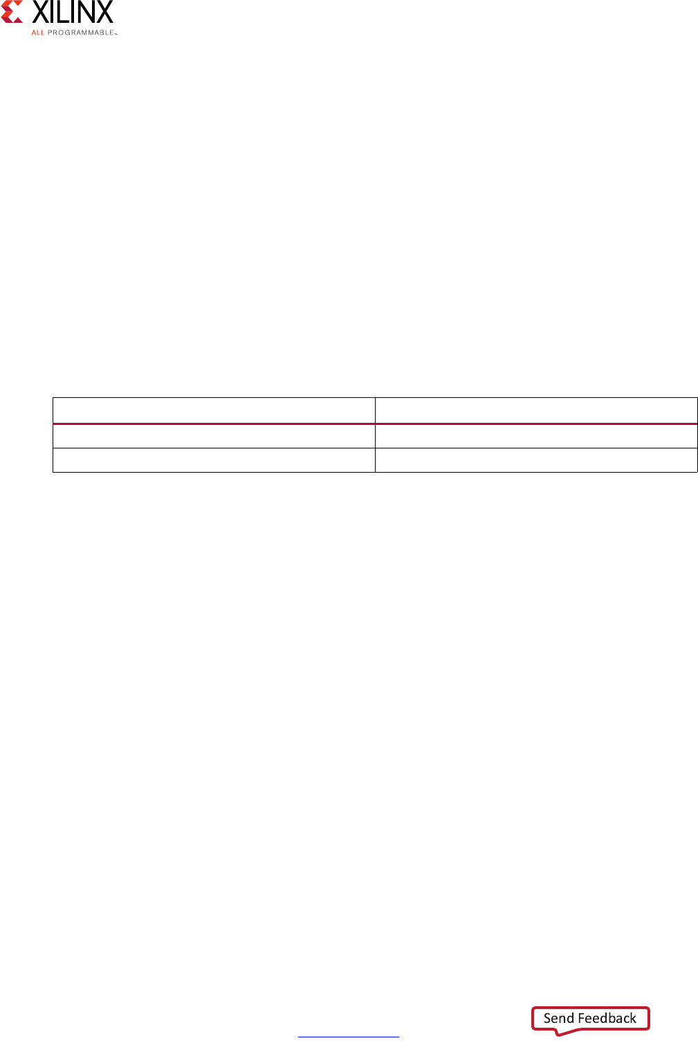
High-Level Synthesis 579
UG902 (v2017.1) April 5, 2017 www.xilinx.com
Chapter 4: High-Level Synthesis Reference Guide
hls::Zero
Synopsis
Set (if computed with image):
template<int ROWS, int COLS, int SRC_T, int DST_T>
void hls::Zero (
hls::Mat<ROWS, COLS, SRC_T>& src,
hls::Mat<ROWS, COLS, DST_T>& dst);
Generate dst image:
template<int ROWS, int COLS, int DST_T>
void hls::Zero (
hls::Mat<ROWS, COLS, DST_T>& dst);
Parameters
Description
• Sets elements in image src to 0.
• Saves the result as image dst.
• Generates a dst image with all element 0 if no input image.
• Image data must be stored in src.
•The image data of dst must be empty before invoking.
• Invoking this function consumes the data in src and fills the image data of dst.
•dst must have the same size and number of channels as src.
OpenCV Reference
•cvSetZero
•cvZero
Table 4-65: Parameters
Parameter Description
src Input image
dst Output image

High-Level Synthesis 580
UG902 (v2017.1) April 5, 2017 www.xilinx.com
Chapter 4: High-Level Synthesis Reference Guide
HLS Linear Algebra Library Functions
This section explains the Vivado HLS linear algebra processing functions.
matrix_multiply
Synopsis
template<
class TransposeFormA,
class TransposeFormB,
int RowsA,
int ColsA,
int RowsB,
int ColsB,
int RowsC,
int ColsC,
typename InputType,
typename OutputType>
void matrix_multiply(
const InputType A[RowsA][ColsA],
const InputType B[RowsB][ColsB],
OutputType C[RowsC][ColsC]);
Description
C=AB
• Computes the product of two matrices, returning a third matrix.
• Optional transposition (and conjugate transposition for complex data types) of input
matrices.
• Alternative architecture provided for unrolled floating-point implementations.
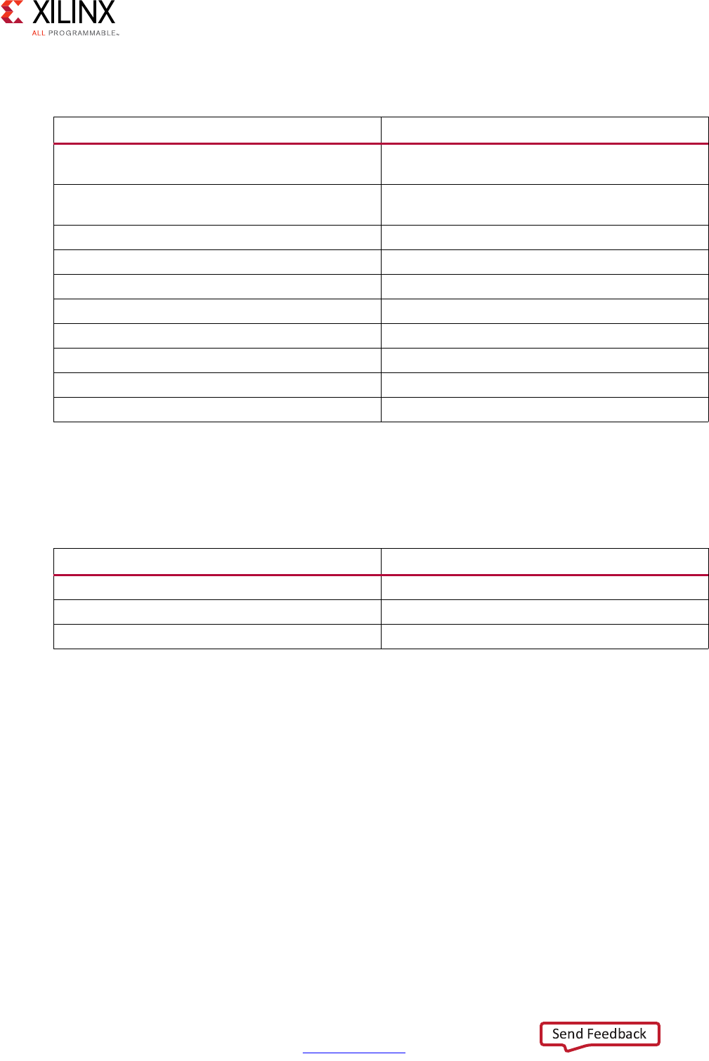
High-Level Synthesis 581
UG902 (v2017.1) April 5, 2017 www.xilinx.com
Chapter 4: High-Level Synthesis Reference Guide
Parameters
The function will throw an assertion and fail to compile, or synthesize, if ColsA != RowsB.
The transpose requirements for A and B are resolved before check is made.
Arguments
Return Values
• Not applicable (void function)
Supported Data Types
•ap_fixed
•float
• x_complex<ap_fixed>
•x_complex<float>
Table 4-66: Parameters
Parameter Description
TransposeFormA Transpose requirement for matrix A; NoTranspose,
Transpose, ConjugateTranspose.
TransposeFormB Transpose requirement for matrix B; NoTranspose,
Transpose, ConjugateTranspose.
RowsA Number of rows in matrix A
ColsA Number of columns in matrix A
RowsB Number of rows in matrix B
ColsB Number of columns in matrix B
RowsC Number of rows in matrix C
ColsC Number of columns in matrix C
InputType Input data type
OutputType Output data type
Table 4-67: Arguments
Argument Description
A First input matrix
B Second input matrix
C AB product output matrix
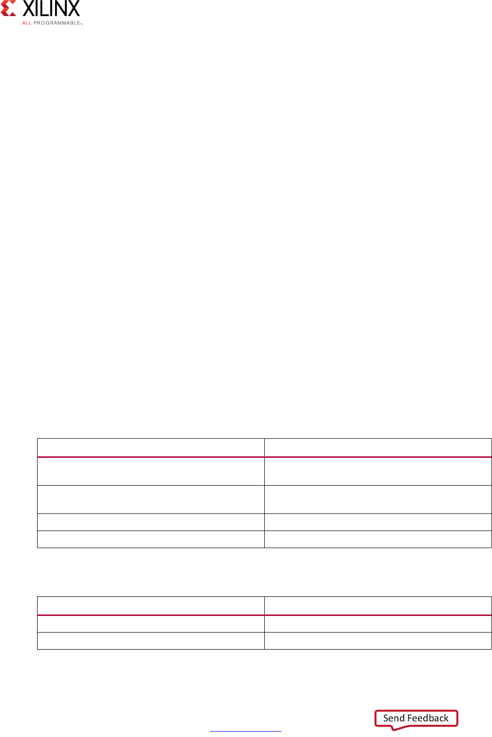
High-Level Synthesis 582
UG902 (v2017.1) April 5, 2017 www.xilinx.com
Chapter 4: High-Level Synthesis Reference Guide
Input Data Assumptions
• For floating point types, subnormal input values are not supported. If used, the
synthesized hardware will flush these to zero, and behavior will differ versus software
simulation.
cholesky
Synopsis
template<
bool LowerTriangularL,
int RowsColsA,
typename InputType,
typename OutputType>
int cholesky(
const InputType A[RowsColsA][RowsColsA],
OutputType L[RowsColsA][RowsColsA])
Description
A=LL*
• Computes the Cholesky decomposition of input matrix A, returning matrix L.
• Output matrix L may be upper triangular or lower triangular based on parameter
LowerTriangularL.
• Elements in the unused portion of matrix L are set to zero.
Parameters
Arguments
Table 4-68: Parameters
Parameter Description
RowsColsA Row and column dimension of input and output
matrices
LowerTriangularL Selects whether lower triangular or upper
triangular output is desired
InputType Input data type
OutputType Output data type
Table 4-69: Arguments
Argument Description
A Hermitian/symmetric positive definite input matrix
L Lower or upper triangular output matrix

High-Level Synthesis 583
UG902 (v2017.1) April 5, 2017 www.xilinx.com
Chapter 4: High-Level Synthesis Reference Guide
Return Values
• 0 = success
• 1 = failure. The function attempted to find the square root of a negative number, that
is, the input matrix A was not Hermitian/symmetric positive definite.
Supported Data Types
•ap_fixed
•float
• x_complex<ap_fixed>
•x_complex<float>
Input Data Assumptions
• The function assumes that the input matrix is symmetric positive definite (Hermitian
positive definite for complex-valued inputs).
• For floating point types, subnormal input values are not supported. If used, the
synthesized hardware will flush these to zero, and behavior will differ versus software
simulation.
qrf
Synopsis
template<
bool TransposeQ,
int RowsA,
int ColsA,
typename InputType,
typename OutputType>
void qrf(
const InputType A[RowsA][ColsA],
OutputType Q[RowsA][RowsA],
OutputType R[RowsA][ColsA])
Description
A=QR
• Computes the full QR factorization (QR decomposition) of input matrix A, producing
orthogonal output matrix Q and upper-triangular matrix R.
• Output matrix Q may be optionally transposed based on parameter TransposeQ.
• Lower triangular elements of output matrix R are not zeroed.
• The thin (also known as economy) QR decomposition is not implemented.

High-Level Synthesis 584
UG902 (v2017.1) April 5, 2017 www.xilinx.com
Chapter 4: High-Level Synthesis Reference Guide
Parameters
• The function will fail to compile, or synthesize, if RowsA < ColsA.
Arguments
Return Values
• Not applicable (void function)
Supported Data Types
•float
•x_complex<float>
Input Data Assumptions
• For floating point types, subnormal input values are not supported. If used, the
synthesized hardware will flush these to zero, and behavior will differ versus software
simulation.
cholesky_inverse
Synopsis
template <
int RowsColsA,
typename InputType,
typename OutputType>
void cholesky_inverse(const InputType A[RowsColsA][RowsColsA],
OutputType InverseA[RowsColsA][RowsColsA],
int& cholesky_success)
Table 4-70: Parameters
Parameter Description
TransposeQ Selects whether Q matrix should be transposed or
not.
RowsA Number of rows in input matrix A
ColsA Number of columns in input matrix A
InputType Input data type
OutputType Output data type
Table 4-71: Arguments
Argument Description
AInput matrix
Q Orthogonal output matrix
R Upper triangular output matrix
High-Level Synthesis 585
UG902 (v2017.1) April 5, 2017 www.xilinx.com
Chapter 4: High-Level Synthesis Reference Guide
Description
AA-1 = I
• Computes the inverse of symmetric positive definite input matrix A by the Cholesky
decomposition method, producing matrix InverseA.
Parameters
Arguments
Return Values
• Not applicable (void function)
Supported Data Types
•ap_fixed
•float
• x_complex<ap_fixed>
•x_complex<float>
Input Data Assumptions
• The function assumes that the input matrix is symmetric positive definite (Hermitian
positive definite for complex-valued inputs).
Table 4-72: Parameters
Parameter Description
RowsColsA Row and column dimension of input and output
matrices
InputType Input data type
OutputType Output data type
Table 4-73: Arguments
Argument Description
A Square Hermitian/symmetric positive definite
input matrix
InverseA Inverse of input matrix
cholesky_success 0 = success
1 = failure. The Cholesky function attempted to
find the square root of a negative number. The
input matrix A was not symmetric positive definite.
High-Level Synthesis 586
UG902 (v2017.1) April 5, 2017 www.xilinx.com
Chapter 4: High-Level Synthesis Reference Guide
• For floating point types, subnormal input values are not supported. If used, the
synthesized hardware will flush these to zero, and behavior will differ versus software
simulation.
qr_inverse
Synopsis
template <
int RowsColsA,
typename InputType,
typename OutputType>
void qr_inverse(const InputType A[RowsColsA][RowsColsA],
OutputType InverseA[RowsColsA][RowsColsA],
int& A_singular)
Description
AA-1=I
• Computes the inverse of input matrix A by the QR factorization method, producing
matrix InverseA.
Parameters
Arguments
Return Values
• Not applicable (void function)
Table 4-74: Parameters
Parameter Description
RowsColsA Row and column dimension of input and output
matrices.
InputType Input data type
OutputType Output data type
Table 4-75: Arguments
Argument Description
AInput matrix A
InverseA Inverse of input matrix
A_singular 0 = success
1 = matrix A is singular

High-Level Synthesis 587
UG902 (v2017.1) April 5, 2017 www.xilinx.com
Chapter 4: High-Level Synthesis Reference Guide
Supported Data Types
•float
•x_complex<float>
Input Data Assumptions
• For floating point types, subnormal input values are not supported. If used, the
synthesized hardware will flush these to zero, and behavior will differ versus software
simulation.
svd
Synopsis
template<
int RowsA,
int ColsA,
typename InputType,
typename OutputType>
void svd(
const InputType A[RowsA][ColsA],
OutputType S[RowsA][ColsA],
OutputType U[RowsA][RowsA],
OutputType V[ColsA][ColsA])
Description
A=USV*
• Computes the singular value decomposition of input matrix A, producing matrices U, S
and V.
• Supports only square matrix.
• Implemented using the iterative two-sided Jacobi method.
Parameters
• The function will throw an assertion and fail to compile, or synthesize, if RowsA !=
ColsA.
Table 4-76: Parameters
Parameter Description
RowsA Row dimension
ColsA Column dimension
InputType Input data type
OutputType Output data type

High-Level Synthesis 588
UG902 (v2017.1) April 5, 2017 www.xilinx.com
Chapter 4: High-Level Synthesis Reference Guide
Arguments
Return Values
• Not applicable (void function)
Supported Data Types
•float
•x_complex<float>
Input Data Assumptions
• For floating point types, subnormal input values are not supported. If used, the
synthesized hardware will flush these to zero, and behavior will differ versus software
simulation.
Examples
The examples provide a basic test-bench and demonstrate how to parameterize and
instantiate each Linear Algebra function. One or more examples for each function are
available in the Vivado HLS examples directory:
<VIVADO_HLS>/examples/design/linear_algebra
Each example contains the following files:
•<example>.cpp: Top-level synthesis wrapper instantiating the library function.
•<example>.h: Header file defining matrix size, data type and, where applicable,
architecture selection.
•<example>_tb.cpp: Basic test-bench instantiating top-level synthesis wrapper.
•run_hls.tcl: Tcl commands to set up the example Vivado HLS project:
vivado_hls -f run_hls.tcl
•directives.tcl: (Optional) Additional Tcl commands applying
optimization/implementation directives.
Table 4-77: Arguments
Argument Description
AInput matrix
S Singular values of input matrix
U Left singular vectors of input matrix
V Right singular vectors of input matrix

High-Level Synthesis 589
UG902 (v2017.1) April 5, 2017 www.xilinx.com
Chapter 4: High-Level Synthesis Reference Guide
HLS DSP Library Functions
The HLS DSP library contains building block functions for DSP system modeling in C++ with
an emphasis on functions used in SDR applications.
HLS DSP Functions
This section explains the Vivado HLS DSP processing functions.
awgn
Synopsis
template<
int OutputWidth>
class awgn {
public:
typedef ap_ufixed<8,4, AP_RND, AP_SAT> t_ input_scale;
static const int LFSR_SECTION_WIDTH = 32;
static const int NUM_NOISE_GENS = 4;
static const int LFSR_WIDTH = LFSR_SECTION_WIDTH*NUM_NOISE_GENS;
void awgn(ap_uint<LFSR_WIDTH> seed);
void ~awgn();
void operator()(t_input_scale &snr,
ap_int<OutputWidth> &noise);
Description
• Outputs Gaussian noise of a magnitude determined by input signal-to-noise ratio
(SNR). 0 dB for a BPSK signal results in a bit error rate (BER) of approximately 7%. This is
because for Eb/N0 = 0, Eb = 1, but N0 / 2 = noise power for a BPSK channel, resulting
in noise variance half that of the signal variance. For more information, see the AWGN
page (www.mathworks.com/help/comm/ug/awgn-channel.html) on the MathWorks
website.
• The SNR input represents signal-to-noise ratio in decibels in the range [0.0 to 16.0) in
steps of 1/16 of a decibel.
• If the noise value exceeds that which can be described by the configuration, it saturates
at the maximum positive or negative value appropriately.
• The function uses multiple individual noise generators that are summed, which takes
advantage of the central limit theorem, to create the output value. By default, these
multiple generators are pipelined and unrolled, because the expected target
application is for high-rate BER testing where a high clock rate and therefore, an
Initiation Interval of 1 is expected.
High-Level Synthesis 590
UG902 (v2017.1) April 5, 2017 www.xilinx.com
Chapter 4: High-Level Synthesis Reference Guide
Parameters
Note: Parameters are checked during C simulation to verify that the template parameter
configuration is legal.
Arguments
Return Values
• Not applicable (void function)
Supported Base Data Types
•Input
°ap_ufixed
See definition of typedef t_ input_scale in header file hls_awgn.h for details.
•Output
°ap_int
Input Data Assumptions
•None
Table 4-78: Parameters
Template Parameter Description
OutputWidth The number of bits in the output value. The SNR
specifies the magnitude of noise relative to a soft
BPSK signal with values 01000… and 11000…
Range 8 to 32 bits.
Table 4-79: Constructor Argument
Argument Description
seed The seed value for the LFSRs within the noise
generators.
Table 4-80: Arguments
Argument Description
snr Signal-to-noise ratio input
noise Output noise

High-Level Synthesis 591
UG902 (v2017.1) April 5, 2017 www.xilinx.com
Chapter 4: High-Level Synthesis Reference Guide
qam_mod
Synopsis
template<
class Constellation,
int OutputWidth>
class qam_mod {
public:
typedef ap_int<OutputWidth> t_outcomponent;
typedef std::complex< t_outcomponent > t_iq;
void qam_mod();
void ~qam_mod();
void operator()(const typename Constellation::t_symbol &symbol,
t_iq &outputdata);
Description
• Converts an input symbol (one of four values for QPSK, one of sixteen for QAM16, or
one of sixty-four for QAM64) into an output value in complex form with I and Q
components each of OutputWidth bits.
• Where OutputWidth is greater than the minimum required to describe the I and Q
values, and zeros are concatenated to the least significant bits until the output word is
OutputWidth wide, for example, symbol 0 of QPSK output to 8 bits is I = Q = 01100000.
Parameters
Note: Parameters are checked during C simulation to verify that the template parameter
configuration is legal.
Arguments
Return Values
• Not applicable (void function)
Table 4-81: Parameters
Template Parameter Description
Constellation The selection of QAM type. One of QPSK, QAM4
(same as QPSK), QAM16, or QAM64. Essentially this
is the selection of bits per symbol.
OutputWidth Describes the number of bits in each component of
the output value, for example, a value of 8 gives an
8-bit real and 8-bit imaginary value.
Table 4-82: Arguments
Argument Description
symbol Input symbol data
outputData Modulated output data

High-Level Synthesis 592
UG902 (v2017.1) April 5, 2017 www.xilinx.com
Chapter 4: High-Level Synthesis Reference Guide
Supported Base Data Types
•Input
°ap_uint
See definition of classes QPSK, QAM4, QAM16 and QAM64 in
utils/hls_dsp_common_utils.h for details.
•Output
°std::complex< ap_int >
Input Data Assumptions
•None
qam_demod
Synopsis
template<
Class Constellation,
int InputWidth>
class qam_demod {
public:
typedef ap_int<InputWidth> t_incomponent;
typedef std::complex< t_incomponent > t_in;
void qam_demod();
void ~qam_demod();
void operator()(const t_in &inputData,
typename Constellation::t_symbol &symbol);
Description
• Accepts an input of complex type with I and Q components each of InputWidth,
matches this to the nearest point in the QAM type selected, and outputs the
corresponding symbol value of that point in the constellation.
• The output is a hard-decision.
Parameters
Table 4-83: Parameters
Template Parameter Description
Constellation One of QPSK, QAM4 (same as QPSK), QAM16, or
QAM64.
InputWidth Describes the number of bits in each component of
the input value, for example, a value of 8 gives an
8-bit real and 8-bit imaginary value.
High-Level Synthesis 593
UG902 (v2017.1) April 5, 2017 www.xilinx.com
Chapter 4: High-Level Synthesis Reference Guide
Note: Parameters are checked during C simulation to verify that the template parameter
configuration is legal.
Arguments
Return Values
• Not applicable (void function)
Supported Base Data Types
•Input
°std::complex< ap_int >
•Output
°ap_uint
See definition of classes QPSK, QAM4, QAM16, and QAM64 in
utils/hls_dsp_common_utils.h for details.
Input Data Assumptions
•None
Table 4-84: Arguments
Argument Description
inputData Modulated input data
symbol Demodulated output symbol
High-Level Synthesis 594
UG902 (v2017.1) April 5, 2017 www.xilinx.com
Chapter 4: High-Level Synthesis Reference Guide
nco
Synopsis
template<
int AccumWidth,
int PhaseAngleWidth,
int SuperSampleRate,
int OutputWidth,
class DualOutputCmpyImpl,
class SingleOutputCmpyImpl,
class SingleOutputNegCmpyImpl>
class nco {
public:
void nco(const ap_uint<AccumWidth> InitPinc,
const ap_uint<AccumWidth> InitPoff);
void ~nco();
void operator()(
stream< ap_uint<AccumWidth> > &pinc,
stream< ap_uint<AccumWidth> > &poff,
stream< t_nco_output_data<SuperSampleRate,OutputWidth> >
&outputData
);
Description
• Performs a numerically controlled oscillator (NCO) function.
• Supports super sample rate (SSR), where the sample rate exceeds the clock rate, so
multiple parallel data samples must be output on each clock cycle.
• When in SSR mode, a change to phase increment (pinc) prompts an internal interrupt.
This does not cause a disturbance to the output samples unless two or more changes
to pinc occur less than N cycles apart where N is SuperSampleRate/2 +1.
Parameters
Table 4-85: Parameters
Template Parameter Description
AccumWidth Number of bits in the phase accumulator. This
determines the precision of the frequency that can
be synthesized. Range 4 to 48.
PhaseAngleWidth Number of bits used in the sin/cos lookup directly.
Larger values give more accurate output at the
expense of lookup table size. Range 4 to 16.
SuperSampleRate Number of output samples per clock cycle. Range
1 to 16.
OutputWidth Width of each output (sine and cosine). Range 4 to
32.

High-Level Synthesis 595
UG902 (v2017.1) April 5, 2017 www.xilinx.com
Chapter 4: High-Level Synthesis Reference Guide
Note: Parameters are checked during C simulation to verify that the template parameter
configuration is legal.
Arguments
Return Values
• Not applicable (void function)
DualOutputCmpyImpl Select whether to implement dual-output complex
multipliers with 5-multiplier (5 DSP48) or
4-multiplier (6 DSP48) architecture using classes
NcoDualOutputCmpyFiveMult or
NcoDualOutputCmpyFourMult. See hls_nco.h for
details.
SingleOutputCmpyImpl Select whether to implement single-output
complex multipliers with 3-multiplier (3 DSP48) or
4-multiplier (4 DSP48) architecture using classes
NcoSingleOutputCmpyThreeMult or
NcoSingleOutputCmpyFourMult. See hls_nco.h for
details.
SingleOutputNegCmpyImpl Select whether to implement single-output
negated complex multipliers with 3-multiplier (3
DSP48) or 4-multiplier (4 DSP48) architecture using
classes NcoSingleOutputCmpyThreeMult or
NcoSingleOutputCmpyFourMult. See hls_nco.h for
details.
Table 4-86: Arguments
Argument Description
pinc Pinc is Phase Increment. The phase of the output
advances by pinc/2AccumWidth *2π each sample.
poff Poff is Phase Offset. This is added to the
accumulated phase. The phase of the output is
offset by poff/2AccumWidth *2π.
outputData Sine and cosine output. The magnitude of the
output components is approximately
cos(ϕ)*2OutputWidth-1 and sin(ϕ)*2OutputWidth-1,
where ϕ is the phase described by the phase
accumulator, appropriately offset by poff.
Table 4-85: Parameters (Cont’d)
Template Parameter Description

High-Level Synthesis 596
UG902 (v2017.1) April 5, 2017 www.xilinx.com
Chapter 4: High-Level Synthesis Reference Guide
Supported Base Data Types
•Input
°ap_uint
•Output
°std::complex< ap_int >
See definition of struct t_nco_output_data in hls_nco.h for details.
Input Data Assumptions
•None
convolution_encoder
Synopsis
template<
int OutputWidth,
bool Punctured,
bool DualOutput,
int InputRate,
int OutputRate,
int ConstraintLength,
int PunctureCode0,
int PunctureCode1,
int ConvolutionCode0,
int ConvolutionCode1,
int ConvolutionCode2,
int ConvolutionCode3,
int ConvolutionCode4,
int ConvolutionCode5,
int ConvolutionCode6>
class convolution_encoder {
public:
convolution_encoder();
~convolution_encoder();
void operator()(stream< ap_uint<1> > &inputData,
stream< ap_uint<OutputWidth> > &outputData);
Description
• Performs convolutional encoding of an input data stream based on user-defined
convolution codes and constraint length
• Optional puncturing of data
• Optional dual channel output

High-Level Synthesis 597
UG902 (v2017.1) April 5, 2017 www.xilinx.com
Chapter 4: High-Level Synthesis Reference Guide
Parameters
Note: Parameters are checked during C simulation to verify that the template parameter
configuration is legal.
Arguments
Table 4-87: Parameters
Template Parameter Description
OutputWidth Defines number of bits in the output bus. 1 bit
when Punctured=true and DualOutput=false, 2
bits when DualOutput=true, else OutputRate bits.
Punctured When true, enables puncturing of data.
DualOutput When true, enables dual outputs with punctured
data.
InputRate Defines numerator of code rate.
OutputRate Defines denominator of code rate.
ConstraintLength The constraint length, K, is the number of registers
in the encoder plus one.
PunctureCode0 When Punctured=true, puncture code for output 0.
Length (in binary) must equal the puncture input
rate. Total number of 1s in both PunctureCode
parameters equals the output rate.
PunctureCode1 When Punctured=true, puncture code for output 1.
Length (in binary) must equal the puncture input
rate. Total number of 1s in both PunctureCode
parameters equals the output rate.
ConvolutionCode0 Convolution code for rates 1/2 to 1/7.
Length (in binary) for all convolution codes (if
used) must equal the constraint length value.
ConvolutionCode1 Convolution code for rates 1/2 to 1/7.
ConvolutionCode2 Convolution code for rates 1/3 to 1/7.
ConvolutionCode3 Convolution code for rates 1/4 to 1/7.
ConvolutionCode4 Convolution code for rates 1/5 to 1/7.
ConvolutionCode5 Convolution code for rates 1/6 to 1/7.
ConvolutionCode6 Convolution code for rate 1/7.
Table 4-88: Arguments
Argument Description
inputData Single-bit data stream to be encoded.
outputData Encoded data stream. OutputRate-bits wide unless
Punctured=true (1-bit wide) or DualOutput=true
(2-bits wide).

High-Level Synthesis 598
UG902 (v2017.1) April 5, 2017 www.xilinx.com
Chapter 4: High-Level Synthesis Reference Guide
Return Values
• Not applicable (void function)
Supported Base Data Types
•ap_uint
Input Data Assumptions
•None
viterbi_decoder
Synopsis
template<
int ConstraintLength,
int TracebackLength,
bool HasEraseInput,
bool SoftData,
int InputDataWidth,
int SoftDataFormat,
int OutputRate,
int ConvolutionCode0,
int ConvolutionCode1,
int ConvolutionCode2,
int ConvolutionCode3,
int ConvolutionCode4,
int ConvolutionCode5,
int ConvolutionCode6>
class viterbi_decoder {
public:
viterbi_decoder();
~viterbi_decoder();
void operator()(stream<
viterbi_decoder_input<OutputRate,InputDataWidth,HasEraseInput> > &inputData,
stream< ap_uint<1> > &outputData)
Description
• Performs Viterbi decoding of a convolutionally encoded data stream
• Supports hard or soft data
• Supports offset binary and signed magnitude soft data formats
• Supports erasures (puncturing)

High-Level Synthesis 599
UG902 (v2017.1) April 5, 2017 www.xilinx.com
Chapter 4: High-Level Synthesis Reference Guide
Parameters
Note: Parameters are checked during C simulation to verify that the template parameter
configuration is legal.
Arguments
Table 4-89: Parameters
Template Parameter Description
ConstraintLength The constraint length, K. Supported range is 3 to 9.
TracebackLength Number of states to trace back through the trellis
during decoding. Use at least 6x ConstraintLength,
or at least 12x ConstraintLength for punctured
codes.
HasEraseInput When true, an Erase input is present on the core to
flag erasures (null symbols) in a punctured code.
SoftData When true, the function accepts soft (multi-bit)
input data.
InputDataWidth Specifies width of the input data. Set to 1 for hard
data and 3-5 for soft data.
SoftDataFormat Specifies soft data formatting. 0 -> Signed
Magnitude, 1 -> Offset Binary.
OutputRate Specifies output rate of the matching convolution
encoder. Determines number of inputs buses for
decoder.
ConvolutionCode0 Convolution code for rates 1/2 to 1/7.
Length (in binary) for all convolution codes (if
used) must equal the constraint length value.
ConvolutionCode1 Convolution code for rates 1/2 to 1/7.
ConvolutionCode2 Convolution code for rates 1/3 to 1/7.
ConvolutionCode3 Convolution code for rates 1/4 to 1/7.
ConvolutionCode4 Convolution code for rates 1/5 to 1/7.
ConvolutionCode5 Convolution code for rates 1/6 to 1/7.
ConvolutionCode6 Convolution code for rate 1/7.
Table 4-90: Arguments
Argument Description
inputData Convolution-encoded data stream with
accompanying Erase signals if a punctured code is
used. Data bus is OutputRate*InputDataWidth-bits
wide. Erase bus is OutputRate bits wide.
outputData Decoded single-bit data stream.

High-Level Synthesis 600
UG902 (v2017.1) April 5, 2017 www.xilinx.com
Chapter 4: High-Level Synthesis Reference Guide
Return Values
• Not applicable (void function)
Supported Base Data Types
•Input
°ap_uint
See definition of struct viterbi_decoder_input in hls_viterbi_decoder.h for details.
•Output
°ap_uint
Input Data Assumptions
•None
atan2
Synopsis
template <
int PhaseFormat,
int InputWidth,
int OutputWidth,
int RoundMode>
void atan2(const typename atan2_input<InputWidth>::cartesian &x,
typename atan2_output<OutputWidth>::phase &atanX)
Description
• CORDIC-based fixed-point implementation of two-argument arctangent
• Configurable input and output widths
• Configurable phase format
• Configurable rounding mode
High-Level Synthesis 601
UG902 (v2017.1) April 5, 2017 www.xilinx.com
Chapter 4: High-Level Synthesis Reference Guide
Parameters
Note: Parameters are checked during C simulation to verify that the template parameter
configuration is legal.
Arguments
Return Values
• Not applicable (void function)
Supported Base Data Types
•Input
°std::complex< ap_fixed >
See definitions of struct cordic_inputs in hls_cordic_functions.h and struct
atan2_input in hls_atan2_cordic.h for details.
•Output
°ap_fixed
See definitions of struct cordic_outputs in hls_cordic_functions.h and struct
atan2_output in hls_atan2_cordic.h for details.
Table 4-91: Parameters
Template Parameter Description
PhaseFormat Selects whether the phase is expressed in radians
or scaled radians (π * 1 radian).
InputWidth Defines overall input data width.
OutputWidth Defines overall output data width.
RoundMode Selects the rounding mode to apply to the output
data:
0=Truncate
1=Round-to-positive-infinity
2=Round-to-positive-and-negative-infinity
3=Round-to-nearest-even
Table 4-92: Arguments
Argument Description
x Input data with two integer bits and InputWidth-2
fractional bits in the range [-1,1].
atanX Four quadrant arctangent of x with three integer
bits and OutputWidth-3 fractional bits in the range
[-1,1].

High-Level Synthesis 602
UG902 (v2017.1) April 5, 2017 www.xilinx.com
Chapter 4: High-Level Synthesis Reference Guide
Input Data Assumptions
•None
sqrt
Synopsis
template <
int DataFormat,
int InputWidth,
int OutputWidth,
int RoundMode>
void sqrt(const typename sqrt_input<InputWidth, DataFormat>::in &x,
typename sqrt_output<OutputWidth, DataFormat>::out &sqrtX)
Description
• CORDIC-based fixed-point implementation of square root
• Unsigned fractional or unsigned integer data formats supported
• Configurable rounding mode
Parameters
Note: Parameters are checked during C simulation to verify that the template parameter
configuration is legal.
Arguments
Table 4-93: Parameters
Template Parameter Description
DataFormat Selects between unsigned fraction (with integer
width of 1 bit) and unsigned integer formats.
InputWidth Defines overall input data width.
OutputWidth Defines overall output data width.
RoundMode Selects the rounding mode to apply to the output
data:
0=Truncate
1=Round-to-positive-infinity
2=round-to-positive-and-negative-infinity
3=Round-to-nearest-even
Table 4-94: Arguments
Argument Description
xInput data.
sqrtX Square root of input data.

High-Level Synthesis 603
UG902 (v2017.1) April 5, 2017 www.xilinx.com
Chapter 4: High-Level Synthesis Reference Guide
Return Values
• Not applicable (void function)
Supported Base Data Types
•Input
°ap_ufixed
°ap_uint
See definitions of struct cordic_inputs in hls_cordic_functions.h and struct sqrt_input
in hls_sqrt_cordic.h for details.
•Output
°ap_ufixed
°ap_uint
See definitions of struct cordic_inputs in hls_cordic_functions.h and struct sqrt_input
in hls_sqrt_cordic.h for details.
Input Data Assumptions
•None
cmpy
Synopsis
•Scalar Interface
template <
class Architecture,
int W1, int I1, ap_q_mode Q1, ap_o_mode O1, int N1,
int W2, int I2, ap_q_mode Q2, ap_o_mode O2, int N2>
void cmpy (const ap_fixed<W1, I1, Q1, O1, N1> &ar,
const ap_fixed<W1, I1, Q1, O1, N1> &ai,
const ap_fixed<W1, I1, Q1, O1, N1> &br,
const ap_fixed<W1, I1, Q1, O1, N1> &bi,
ap_fixed<W2, I2, Q2, O2, N2> &pr,
ap_fixed<W2, I2, Q2, O2, N2> &pi);
• std::complex interface
template <
class Architecture,
int W1, int I1, ap_q_mode Q1, ap_o_mode O1, int N1,
int W2, int I2, ap_q_mode Q2, ap_o_mode O2, int N2>
void cmpy (const std::complex< ap_fixed<W1, I1, Q1, O1, N1> > &a,
const std::complex< ap_fixed<W1, I1, Q1, O1, N1> > &b,
std::complex< ap_fixed<W2, I2, Q2, O2, N2> > &p);
High-Level Synthesis 604
UG902 (v2017.1) April 5, 2017 www.xilinx.com
Chapter 4: High-Level Synthesis Reference Guide
Description
• Performs fixed-point complex multiplication
• Implements either three-multiplier or four-multiplier structure
• Supports scalar or std::complex interfaces
Parameters
Arguments
Return Values
• Not applicable (void function)
Supported Base Data Types
•ap_fixed
• std::complex< ap_fixed>
Table 4-95: Parameters
Template Parameter Description
Architecture Selects between three-multiplier and
four-multiplier architectures. Specify using structs
CmpyThreeMult or CmpyFourMult.
W1, I1, Q1, O1, N1 Fixed-point parameters for multiplicand and
multiplier.
W2, I2, Q2, O2, N2 Fixed-point parameters for product.
Table 4-96: Scalar Interface Arguments
Argument Description
ar Multiplicand real component
ai Multiplicand imaginary component
br Multiplier real component
bi Multiplier imaginary component
pr Product real component
pi Product imaginary component
Table 4-97: std::complex Interface Arguments
Argument Description
a Multiplicand
b Multiplier
pProduct

High-Level Synthesis 605
UG902 (v2017.1) April 5, 2017 www.xilinx.com
Chapter 4: High-Level Synthesis Reference Guide
Input Data Assumptions
•None
HLS DSP Design Examples
The Vivado HLS DSP design examples provide a basic test bench and demonstrate how to
parameterize and instantiate each function. The design examples provide one or more
examples for each function.
To open the Vivado HLS design examples from the Welcome Page, click Open Example
Project. In the Examples wizard, select a design from the Design Examples > dsp folder.
Note: The Welcome Page appears when you invoke the Vivado HLS GUI. You can access it at any
time by selecting Help > Welcome.
You can also open the design examples directly from the Vivado Design Suite installation
area: Vivado_HLS\2017.x\examples\design\dsp.
Each example contains the following files:
•<example>.cpp: Top-level synthesis wrapper that instantiates the library class.
•<example>.h: Header file that defines parameter values.
•<example>_tb.cpp: Basic test bench that exercises the top-level synthesis wrapper.
•run_hls.tcl: Tcl commands to set up the example Vivado HLS project:
vivado_hls -f run_hls.tcl
Note: Some of the design examples also include a directives.tcl file, which provides additional
Tcl commands for applying optimization and implementation directives.
C Arbitrary Precision Types
This section discusses:
• The Arbitrary Precision (AP) types provided for C language designs by Vivado HLS.
• The associated functions for C int#w types.
Compiling [u]int#W Types
To use the [u]int#W types, you must include the ap_cint.h header file in all source files
that reference [u]int#W variables.

High-Level Synthesis 606
UG902 (v2017.1) April 5, 2017 www.xilinx.com
Chapter 4: High-Level Synthesis Reference Guide
When compiling software models that use these types, it may be necessary to specify the
location of the Vivado HLS header files, for example, by adding the
“-I/<HLS_HOME>/include” option for gcc compilation.
Declaring/Defining [u]int#W Variables
There are separate signed and unsigned C types, respectively:
• int#W
• uint#W
where
•#W specifies the total width of the variable being declared.
User-defined types may be created with the C/C++ ‘typedef’ statement as shown in the
following examples:
include "ap_cint.h" // use [u]int#W types
typedef uint128 uint128_t; // 128-bit user defined type
int96 my_wide_var; // a global variable declaration
The maximum width allowed is 1024 bits.
Initialization and Assignment from Constants (Literals)
A [u]int#W variable can be initialized with the same integer constants that are supported
for the native integer data types. The constants are zero or sign extended to the full width
of the [u]int#W variable.
#include "ap_cint.h"
uint15 a = 0;
uint52 b = 1234567890U;
uint52 c = 0o12345670UL;
uint96 d = 0x123456789ABCDEFULL;
For bit-widths greater than 64-bit, the following functions can be used.
apint_string2bits()
This section also discusses use of the related functions:
• apint_string2bits_bin()
• apint_string2bits_oct()
• apint_string2bits_hex()

High-Level Synthesis 607
UG902 (v2017.1) April 5, 2017 www.xilinx.com
Chapter 4: High-Level Synthesis Reference Guide
These functions convert a constant character string of digits, specified within the
constraints of the radix (decimal, binary, octal, hexadecimal), into the corresponding value
with the given bit-width N. For any radix, the number can be preceded with the minus sign
to indicate a negative value.
int#W apint_string2bits[_radix](const char*, int N)
This is used to construct integer constants with values that are larger than those already
permitted by the C language. While smaller values also work, they are easier to specify with
existing C language constant value constructs.
#include <stdio.h>
#include "ap_cint.h"
int128 a;
// Set a to the value hex 00000000000000000123456789ABCDF0
a = apint_string2bits_hex(“-123456789ABCDEF”,128);
Values can also be assigned directly from a character string.
apint_vstring2bits()
This function converts a character string of digits, specified within the constraints of the
hexadecimal radix, into the corresponding value with the given bit-width N. The number can
be preceded with the minus sign to indicate a negative value.
This is used to construct integer constants with values that are larger than those already
permitted by the C language. The function is typically used in a test bench to read
information from a file.
Given file test.dat contains the following data:
123456789ABCDEF
-123456789ABCDEF
-5

High-Level Synthesis 608
UG902 (v2017.1) April 5, 2017 www.xilinx.com
Chapter 4: High-Level Synthesis Reference Guide
The function, used in the test bench, supplies the following values:
#include <stdio.h>
#include "ap_cint.h"
typedef data_t;
int128 test (
int128 t a
) {
return a+1;
}
int main () {
FILE *fp;
char vstring[33];
fp = fopen(test.dat,r);
while (fscanf(fp,%s,vstring)==1) {
// Supply function “test” with the following values
// 00000000000000000123456789ABCDF0
// FFFFFFFFFFFFFFFFFEDCBA9876543212
// FFFFFFFFFFFFFFFFFFFFFFFFFFFFFFFC
test(apint_vstring2bits_hex(vstring,128));
printf(\n);
}
fclose(fp);
return 0;
}

High-Level Synthesis 609
UG902 (v2017.1) April 5, 2017 www.xilinx.com
Chapter 4: High-Level Synthesis Reference Guide
Support for console I/O (Printing)
A [u]int#W variable can be printed with the same conversion specifiers that are supported
for the native integer data types. Only the bits that fit according to the conversion specifier
are printed:
#include "ap_cint.h"
uint164 c = 0x123456789ABCDEFULL;
printf( d%40d\n,c); // Signed integer in decimal format
// d -1985229329
printf( hd%40hd\n,c); // Short integer
// hd -12817
printf( ld%40ld\n,c); // Long integer
// ld 81985529216486895
printf(lld%40lld\n,c); // Long long integer
// lld 81985529216486895
printf( u%40u\n,c); // Unsigned integer in decimal format
// u 2309737967
printf( hu%40hu\n,c);
// hu 52719
printf( lu%40lu\n,c);
// lu 81985529216486895
printf(llu%40llu\n,c);
// llu 81985529216486895
printf( o%40o\n,c); // Unsigned integer in octal format
// o 21152746757
printf( ho%40ho\n,c);
// ho 146757
printf( lo%40lo\n,c);
// lo 4432126361152746757
printf(llo%40llo\n,c);
// llo 4432126361152746757
printf( x%40x\n,c); // Unsigned integer in hexadecimal format [0-9a-f]
// x 89abcdef
printf( hx%40hx\n,c);
// hx cdef
printf( lx%40lx\n,c);
// lx 123456789abcdef
printf(llx%40llx\n,c);
// llx 123456789abcdef
printf( X%40X\n,c); // Unsigned integer in hexadecimal format [0-9A-F]
// X 89ABCDEF
}
As with initialization and assignment to [u]int#W variables, features support printing
values that require more than 64 bits to represent.

High-Level Synthesis 610
UG902 (v2017.1) April 5, 2017 www.xilinx.com
Chapter 4: High-Level Synthesis Reference Guide
apint_print()
This is used to print integers with values that are larger than those already permitted by the
C language. This function prints a value to stdout, interpreted according to the radix (2, 8,
10, 16).
void apint_print(int#N value, int radix)
The following example shows the results when apint_printf() is used:
#include <stdio.h>
#include "ap_cint.h"
int65 Var1 = 44;
apint_print(Var1,2);
//00000000000000000000000000000000000000000000000000000000000101100
apint_print(Var1,8); // 0000000000000000000054
apint_print(Var1,10); // 44
apint_print(Var1,16); // 0000000000000002C
apint_fprint()
This is used to print integers with values that are bigger than those already permitted by the
C language. This function prints a value to a file, interpreted according to the radix (2, 8, 10,
16).
void apint_fprint(FILE* file, int#N value, int radix)
Expressions Involving [u]int#W types
Variables of [u]int#W types may generally be used freely in expressions involving any C
operators. Some behaviors may seem unexpected and require detailed explanation.
Zero- and Sign-Extension on Assignment from Narrower to Wider Variables
When assigning the value of a narrower bit-width signed variable to a wider one, the value
is sign-extended to the width of the destination variable, regardless of its signedness.
Similarly, an unsigned source variable is zero-extended before assignment.
Explicit casting of the source variable might be necessary to ensure expected behavior on
assignment.
Truncation on Assignment of Wider to Narrower Variables
Assigning a wider source variables value to a narrower one leads to truncation of the value.
All bits beyond the most significant bit (MSB) position of the destination variable are lost.

High-Level Synthesis 611
UG902 (v2017.1) April 5, 2017 www.xilinx.com
Chapter 4: High-Level Synthesis Reference Guide
There is no special handling of the sign information during truncation, which may lead to
unexpected behavior. Explicit casting may help avoid this unexpected behavior.
Binary Arithmetic Operators
In general, any valid operation that may be done on a native C integer data type is
supported for [u]int#w types.
Standard binary integer arithmetic operators are overloaded to provide arbitrary precision
arithmetic. All of the following operators take either two operands of [u]int#W or one
[u]int#W type and one C/C++ fundamental integer data type, for example, char, short,
int.
The width and signedness of the resulting value is determined by the width and signedness
of the operands, before sign-extension, zero-padding or truncation are applied based on
the width of the destination variable (or expression). Details of the return value are
described for each operator.
When expressions contain a mix of ap_[u]int and C/C++ fundamental integer types, the
C++ types assume the following widths:
•char: 8-bits
•short: 16-bits
•int: 32-bits
•long: 32-bits
•long long: 64-bits
Addition
[u]int#W::RType [u]int#W::operator + ([u]int#W op)
Produces the sum of two ap_[u]int or one ap_[u]int and a C/C++ integer type.
The width of the sum value is:
• One bit more than the wider of the two operands
• Two bits if and only if the wider is unsigned and the narrower is signed
The sum is treated as signed if either (or both) of the operands is of a signed type.

High-Level Synthesis 612
UG902 (v2017.1) April 5, 2017 www.xilinx.com
Chapter 4: High-Level Synthesis Reference Guide
Subtraction
[u]int#W::RType [u]int#W::operator - ([u]int#W op)
• Produces the difference of two integers.
• The width of the difference value is:
°One bit more than the wider of the two operands
°Two bits if and only if the wider is unsigned and the narrower signed
• This applies before assignment, at which point it is sign-extended, zero-padded, or
truncated based on the width of the destination variable.
• The difference is treated as signed regardless of the signedness of the operands.
Multiplication
[u]int#W::RType [u]int#W::operator * ([u]int#W op)
• Returns the product of two integer values.
• The width of the product is the sum of the widths of the operands.
• The product is treated as a signed type if either of the operands is of a signed type.
Division
[u]int#W::RType [u]int#W::operator / ([u]int#W op)
• Returns the quotient of two integer values.
• The width of the quotient is the width of the dividend if the divisor is an unsigned type;
otherwise it is the width of the dividend plus one.
• The quotient is treated as a signed type if either of the operands is of a signed type.
Modulus
[u]int#W::RType [u]int#W::operator % ([u]int#W op)
• Returns the modulus, or remainder of integer division, for two integer values.
• The width of the modulus is the minimum of the widths of the operands, if they are
both of the same signedness; if the divisor is an unsigned type and the dividend is
signed then the width is that of the divisor plus one.
• The quotient is treated as having the same signedness as the dividend.
Note: Vivado HLS synthesis of the modulus (%) operator will lead to lead to instantiation of
appropriately parameterized Xilinx LogiCORE divider cores in the generated RTL.

High-Level Synthesis 613
UG902 (v2017.1) April 5, 2017 www.xilinx.com
Chapter 4: High-Level Synthesis Reference Guide
Bitwise Logical Operators
The bitwise logical operators all return a value with a width that is the maximum of the
widths of the two operands. They are treated as unsigned if and only if both operands are
unsigned. Otherwise it is of a signed type.
Sign-extension (or zero-padding) may occur, based on the signedness of the expression,
not the destination variable.
Bitwise OR
[u]int#W::RType [u]int#W::operator | ([u]int#W op)
Returns the bitwise OR of the two operands.
Bitwise AND
[u]int#W::RType [u]int#W::operator & ([u]int#W op)
Returns the bitwise AND of the two operands.
Bitwise XOR
[u]int#W::RType [u]int#W::operator ^ ([u]int#W op)
Returns the bitwise XOR of the two operands.
Shift Operators
Each shift operator comes in two versions, one for unsigned right-hand side (RHS) operands
and one for signed RHS.
A negative value supplied to the signed RHS versions reverses the shift operations
direction, that is, a shift by the absolute value of the RHS operand in the opposite direction
occurs.
The shift operators return a value with the same width as the left-hand side (LHS) operand.
As with C/C++, if the LHS operand of a shift-right is a signed type, the sign bit is copied into
the most significant bit positions, maintaining the sign of the LHS operand.
Unsigned Integer Shift Right
[u]int#W [u]int#W::operator >>(ap_uint<int_W2> op)
Integer Shift Right
[u]int#W [u]int#W::operator >>(ap_int<int_W2> op)
Unsigned Integer Shift Left
[u]int#W [u]int#W::operator <<(ap_uint<int_W2> op)

High-Level Synthesis 614
UG902 (v2017.1) April 5, 2017 www.xilinx.com
Chapter 4: High-Level Synthesis Reference Guide
Integer Shift Left
[u]int#W [u]int#W::operator <<(ap_int<int_W2> op)
CAUTION! When assigning the result of a shift-left operator to a wider destination variable, some (or
all) information may be lost. Xilinx recommends that you explicitly cast the shift expression to the
destination type to avoid unexpected behavior.
Compound Assignment Operators
Vivado HLS supports compound assignment operators:
•*=
•/=
•%=
•+=
•-=
• <<=
• >>=
•&=
•^=
•=
The RHS expression is first evaluated then supplied as the RHS operand to the base
operator. The result is assigned back to the LHS variable. The expression sizing, signedness,
and potential sign-extension or truncation rules apply as discussed above for the relevant
operations.
Relational Operators
Vivado HLS supports all relational operators. They return a Boolean value based on the
result of the comparison. Variables of ap_[u]int types may be compared to C/C++
fundamental integer types with these operators.
Equality
bool [u]int#W::operator == ([u]int#W op)
Inequality
bool [u]int#W::operator != ([u]int#W op)

High-Level Synthesis 615
UG902 (v2017.1) April 5, 2017 www.xilinx.com
Chapter 4: High-Level Synthesis Reference Guide
Less than
bool [u]int#W::operator < ([u]int#W op)
Greater than
bool [u]int#W::operator > ([u]int#W op)
Less than or equal to
bool [u]int#W::operator <= ([u]int#W op)
Greater than or equal to
bool [u]int#W::operator >= ([u]int#W op)
Bit-Level Operation: Support Function
The [u]int#W types allow variables to be expressed with bit-level accuracy. It is often
desirable with hardware algorithms to perform bit-level operations. Vivado HLS provides
the following functions to enable this.
Bit Manipulation
The following methods are included to facilitate common bit-level operations on the value
stored in ap_[u]int type variables.
Length
apint_bitwidthof()
int apint_bitwidthof(type_or_value)
Returns an integer value that provides the number of bits in an arbitrary precision integer
value. It can be used with a type or a value.
int5 Var1, Res1;
Var1= -1;
Res1 = apint_bitwidthof(Var1); // Res1 is assigned 5
Res1 = apint_bitwidthof(int7); // Res1 is assigned 7
Concatenation
apint_concatenate()
int#(N+M) apint_concatenate(int#N first, int#M second)
Concatenates two [u]int#W variables. The width of the returned value is the sum of the
widths of the operands.

High-Level Synthesis 616
UG902 (v2017.1) April 5, 2017 www.xilinx.com
Chapter 4: High-Level Synthesis Reference Guide
The High and Low arguments are placed in the higher and lower order bits of the result
respectively.
RECOMMENDED: To avoid unexpected results, explicitly cast C native types (including integer literals)
to an appropriate [u]int#W type before concatenating.
Bit Selection
apint_get_bit()
int apint_get_bit(int#N source, int index)
Selects one bit from an arbitrary precision integer value and returns it.
The source must be an [u]int#W type. The index argument must be an int value. It
specifies the index of the bit to select. The least significant bit has index 0. The highest
permissible index is one less than the bit-width of this [u]int#W.
Set Bit Value
apint_set_bit()
int#N apint_set_bit(int#N source, int index, int value)
• Sets the specified bit, index, of the [u]int#W instance source to the value specified
(zero or one).
Range Selection
apint_get_range()
int#N apint_get_range(int#N source, int high, int low)
• Returns the value represented by the range of bits specified by the arguments.
•The High argument specifies the most significant bit (MSB) position of the range.
•THE Low argument specifies the least significant bit (LSB) position of the range.
• The LSB of the source variable is in position 0. If the High argument has a value less
than Low, the bits are returned in reverse order.
Set Range Value
apint_set_range()
int#N apint_set_range(int#N source, int high, int low, int#M part)
• Sets the source specified bits between High and Low to the value of the part.

High-Level Synthesis 617
UG902 (v2017.1) April 5, 2017 www.xilinx.com
Chapter 4: High-Level Synthesis Reference Guide
Bit Reduction
AND Reduce
apint_and_reduce()
int apint_and_reduce(int#N value)
• Applies the AND operation on all bits in the value.
• Returns the resulting single bit as an integer value (which can be cast onto a bool).
int5 Var1, Res1;
Var1= -1;
Res1 = apint_and_reduce(Var1); // Res1 is assigned 1
Var1= 1;
Res1 = apint_and_reduce(Var1); // Res1 is assigned 0
• Equivalent to comparing to -1. It returns a 1 if it matches. It returns a 0 if it does not
match. Another interpretation is to check that all bits are one.
OR Reduce
apint_or_reduce()
int apint_or_reduce(int#N value)
• Applies the XOR operation on all bits in the value.
• Returns the resulting single bit as an integer value (which can be cast onto a bool).
• Equivalent to comparing to 0, and return a 0 if it matches, 1 otherwise.
int5 Var1, Res1;
Var1= 1;
Res1 = apint_or_reduce(Var1); // Res1 is assigned 1
Var1= 0;
Res1 = apint_or_reduce(Var1); // Res1 is assigned 0
XOR Reduce
apint_xor_reduce()
int apint_xor_reduce(int#N value)
• Applies the OR operation on all bits in the value.
• Returns the resulting single bit as an integer value (which can be cast onto a bool).
• Equivalent to counting the ones in the word. This operation:
°Returns 0if there is an even number.
°Returns 1if there is an odd number (even parity).

High-Level Synthesis 618
UG902 (v2017.1) April 5, 2017 www.xilinx.com
Chapter 4: High-Level Synthesis Reference Guide
int5 Var1, Res1;
Var1= 0;
Res1 = apint_xor_reduce(Var1); // Res1 is assigned 0
Var1= 1;
Res1 = apint_xor_reduce(Var1); // Res1 is assigned 1
NAND Reduce
apint_nand_reduce()
int apint_nand_reduce(int#N value)
• Applies the NAND operation on all bits in the value.
• Returns the resulting single bit as an integer value (which can be cast onto a bool).
• Equivalent to comparing this value against -1 (all ones) and returning false if it
matches, true otherwise.
int5 Var1, Res1;
Var1= 1;
Res1 = apint_nand_reduce(Var1); // Res1 is assigned 1
Var1= -1;
Res1 = apint_nand_reduce(Var1); // Res1 is assigned 0
NOR Reduce
apint_nor_reduce()
int apint_nor_reduce(int#N value)
• Applies the NOR operation on all bits in the value.
• Returns the resulting single bit as an integer value (which can be cast onto a bool).
• Equivalent to comparing this value against 0 (all zeros) and returning true if it matches,
false otherwise.
int5 Var1, Res1;
Var1= 0;
Res1 = apint_nor_reduce(Var1); // Res1 is assigned 1
Var1= 1;
Res1 = apint_nor_reduce(Var1); // Res1 is assigned 0

High-Level Synthesis 619
UG902 (v2017.1) April 5, 2017 www.xilinx.com
Chapter 4: High-Level Synthesis Reference Guide
XNOR Reduce
apint_xnor_reduce()
int apint_xnor_reduce(int#N value)
• Applies the XNOR operation on all bits in the value.
• Returns the resulting single bit as an integer value (which can be cast onto a bool).
• Equivalent to counting the ones in the word.
• This operation:
°Returns 1 if there is an odd number.
°Returns 0 if there is an even number (odd parity).
int5 Var1, Res1;
Var1= 0;
Res1 = apint_xnor_reduce(Var1); // Res1 is assigned 1
Var1= 1;
Res1 = apint_xnor_reduce(Var1); // Res1 is assigned 0
C++ Arbitrary Precision Types
Vivado HLS provides a C++ template class, ap_[u]int<>, that implements arbitrary
precision (or bit-accurate) integer data types with consistent, bit-accurate behavior
between software and hardware modeling.
This class provides all arithmetic, bitwise, logical and relational operators allowed for native
C integer types. In addition, this class provides methods to handle some useful hardware
operations, such as allowing initialization and conversion of variables of widths greater than
64 bits. Details for all operators and class methods are discussed below.
Compiling ap_[u]int<> Types
To use the ap_[u]int<> classes, you must include the ap_int.h header file in all source
files that reference ap_[u]int<> variables.
When compiling software models that use these classes, it may be necessary to specify the
location of the Vivado HLS header files, for example by adding the
-I/<HLS_HOME>/include option for g++ compilation.
High-Level Synthesis 620
UG902 (v2017.1) April 5, 2017 www.xilinx.com
Chapter 4: High-Level Synthesis Reference Guide
Declaring/Defining ap_[u] Variables
There are separate signed and unsigned classes:
• ap_int<int_W> (signed)
•ap_uint<int_W> (unsigned)
The template parameter int_W specifies the total width of the variable being declared.
User-defined types may be created with the C/C++ typedef statement as shown in the
following examples:
include "ap_int.h"// use ap_[u]fixed<> types
typedef ap_uint<128> uint128_t; // 128-bit user defined type
ap_int<96> my_wide_var; // a global variable declaration
The default maximum width allowed is 1024 bits. This default may be overridden by
defining the macro AP_INT_MAX_W with a positive integer value less than or equal to
32768 before inclusion of the ap_int.h header file.
CAUTION! Setting the value of AP_INT_MAX_W too High may cause slow software compile and run
times.
Following is an example of overriding AP_INT_MAX_W:
#define AP_INT_MAX_W 4096 // Must be defined before next line
#include "ap_int.h"
ap_int<4096> very_wide_var;
Initialization and Assignment from Constants (Literals)
The class constructor and assignment operator overloads, allows initialization of and
assignment to ap_[u]fixed<> variables using standard C/C++ integer literals.
This method of assigning values to ap_[u]fixed<> variables is subject to the limitations
of C++ and the system upon which the software will run. This typically leads to a 64-bit limit
on integer literals (for example, for those LL or ULL suffixes).
To allow assignment of values wider than 64-bits, the ap_[u]fixed<> classes provide
constructors that allow initialization from a string of arbitrary length (less than or equal to
the width of the variable).
By default, the string provided is interpreted as a hexadecimal value as long as it contains
only valid hexadecimal digits (that is, 0-9 and a-f). To assign a value from such a string, an
explicit C++ style cast of the string to the appropriate type must be made.

High-Level Synthesis 621
UG902 (v2017.1) April 5, 2017 www.xilinx.com
Chapter 4: High-Level Synthesis Reference Guide
Following are examples of initialization and assignments, including for values greater than
64-bit, are:
ap_int<42> a_42b_var(-1424692392255LL); // long long decimal format
a_42b_var = 0x14BB648B13FLL; // hexadecimal format
a_42b_var = -1; // negative int literal sign-extended to full width
ap_uint<96> wide_var(“76543210fedcba9876543210”, 16);// Greater than 64-bit
wide_var = ap_int<96>(“0123456789abcdef01234567”, 16);
The ap_[u]<> constructor may be explicitly instructed to interpret the string as
representing the number in radix 2, 8, 10, or 16 formats. This is accomplished by adding the
appropriate radix value as a second parameter to the constructor call.
A compilation error occurs if the string literal contains any characters that are invalid as
digits for the radix specified.
The following examples use different radix formats:
ap_int<6> a_6bit_var(“101010”, 2); // 42d in binary format
a_6bit_var = ap_int<6>(“40”, 8); // 32d in octal format
a_6bit_var = ap_int<6>(“55”, 10); // decimal format
a_6bit_var = ap_int<6>(“2A”, 16); // 42d in hexadecimal format
a_6bit_var = ap_int<6>(“42”, 2); // COMPILE-TIME ERROR! “42” is not binary
The radix of the number encoded in the string can also be inferred by the constructor, when
it is prefixed with a zero (0) followed by one of the following characters: “b”, “o” or “x”. The
prefixes “0b”, “0o” and “0x” correspond to binary, octal and hexadecimal formats
respectively.
The following examples use alternate initializer string formats:
ap_int<6> a_6bit_var(“0b101010”, 2); // 42d in binary format
a_6bit_var = ap_int<6>(“0o40”, 8); // 32d in octal format
a_6bit_var = ap_int<6>(“0x2A”, 16); // 42d in hexidecimal format
a_6bit_var = ap_int<6>(“0b42”, 2); // COMPILE-TIME ERROR! “42” is not binary
If the bit-width is greater than 53-bits, the ap_[u]fixed value must be initialized with a
string, for example:
ap_ufixed<72,10> Val(“2460508560057040035.375”);
Support for Console I/O (Printing)
As with initialization and assignment to ap_[u]fixed<> variables, Vivado HLS supports
printing values that require more than 64-bits to represent.

High-Level Synthesis 622
UG902 (v2017.1) April 5, 2017 www.xilinx.com
Chapter 4: High-Level Synthesis Reference Guide
Using the C++ Standard Output Stream
The easiest way to output any value stored in an ap_[u]int variable is to use the C++
standard output stream:
•std::cout (#include <iostream> or
• <iostream.h>)
The stream insertion operator (<<) is overloaded to correctly output the full range of values
possible for any given ap_[u]fixed variable. The following stream manipulators are also
supported:
• dec (decimal)
• hex (hexadecimal)
• oct (octal)
These allow formatting of the value as indicated.
The following example uses cout to print values:
#include <iostream.h>
// Alternative: #include <iostream>
ap_ufixed<72> Val(“10fedcba9876543210”);
cout << Val << endl; // Yields: “313512663723845890576”
cout << hex << val << endl; // Yields: “10fedcba9876543210”
cout << oct << val << endl; // Yields: “41773345651416625031020”
Using the Standard C Library
You can also use the standard C library (#include <stdio.h>) to print out values larger
than 64-bits:
1. Convert the value to a C++ std::string using the ap_[u]fixed classes method
to_string().
2. Convert the result to a null-terminated C character string using the std::string class
method c_str().

High-Level Synthesis 623
UG902 (v2017.1) April 5, 2017 www.xilinx.com
Chapter 4: High-Level Synthesis Reference Guide
Optional Argument One (Specifying the Radix)
You can pass the ap[u]int::to_string()method an optional argument specifying the
radix of the numerical format desired. The valid radix argument values are:
• 2 (binary) (default)
•8 (octal)
•10 (decimal)
• 16 (hexadecimal)
Optional Argument Two (Printing as Signed Values)
A second optional argument to ap_[u]int::to_string() specifies whether to print the
non-decimal formats as signed values. This argument is boolean. The default value is false,
causing the non-decimal formats to be printed as unsigned values.
The following examples use printf to print values:
ap_int<72> Val(“80fedcba9876543210”);
printf(“%s\n”, Val.to_string().c_str()); // => “80FEDCBA9876543210”
printf(“%s\n”, Val.to_string(10).c_str()); // => “-2342818482890329542128”
printf(“%s\n”, Val.to_string(8).c_str()); // => “401773345651416625031020”
printf(“%s\n”, Val.to_string(16, true).c_str()); // => “-7F0123456789ABCDF0”
Expressions Involving ap_[u]<> types
Variables of ap_[u]<> types may generally be used freely in expressions involving C/C++
operators. Some behaviors may be unexpected. These are discussed in detail below.
Zero- and Sign-Extension on Assignment From Narrower to Wider Variables
When assigning the value of a narrower bit-width signed (ap_int<>) variable to a wider
one, the value is sign-extended to the width of the destination variable, regardless of its
signedness.
Similarly, an unsigned source variable is zero-extended before assignment.

High-Level Synthesis 624
UG902 (v2017.1) April 5, 2017 www.xilinx.com
Chapter 4: High-Level Synthesis Reference Guide
Explicit casting of the source variable may be necessary to ensure expected behavior on
assignment. See the following example:
ap_uint<10> Result;
ap_int<7> Val1 = 0x7f;
ap_uint<6> Val2 = 0x3f;
Result = Val1; // Yields: 0x3ff (sign-extended)
Result = Val2; // Yields: 0x03f (zero-padded)
Result = ap_uint<7>(Val1); // Yields: 0x07f (zero-padded)
Result = ap_int<6>(Val2); // Yields: 0x3ff (sign-extended)
Truncation on Assignment of Wider to Narrower Variables
Assigning the value of a wider source variable to a narrower one leads to truncation of the
value. All bits beyond the most significant bit (MSB) position of the destination variable are
lost.
There is no special handling of the sign information during truncation. This may lead to
unexpected behavior. Explicit casting may help avoid this unexpected behavior.
Class Methods and Operators
The ap_[u]int types do not support implicit conversion from wide ap_[u]int
(>64bits) to builtin C/C++ integer types. For example, the following code example return
s1, because the implicit cast from ap_int[65] to bool in the if-statement returns a 0.
bool nonzero(ap_uint<65> data) {
return data; // This leads to implicit truncation to 64b int
}
int main() {
if (nonzero((ap_uint<65>)1 << 64)) {
return 0;
}
printf(FAIL\n);
return 1;
}
To convert wide ap_[u]int types to built-in integers, use the explicit conversion functions
included with the ap_[u]int types:
• to_int()
• to_long()
• to_bool()
In general, any valid operation that can be done on a native C/C++ integer data type is
supported using operator overloading for ap_[u]int types.

High-Level Synthesis 625
UG902 (v2017.1) April 5, 2017 www.xilinx.com
Chapter 4: High-Level Synthesis Reference Guide
In addition to these overloaded operators, some class specific operators and methods are
included to ease bit-level operations.
Binary Arithmetic Operators
Standard binary integer arithmetic operators are overloaded to provide arbitrary precision
arithmetic. These operators take either:
•Two operands of ap_[u]int, or
•One ap_[u]int type and one C/C++ fundamental integer data type
For example:
•char
•short
•int
The width and signedness of the resulting value is determined by the width and signedness
of the operands, before sign-extension, zero-padding or truncation are applied based on
the width of the destination variable (or expression). Details of the return value are
described for each operator.
When expressions contain a mix of ap_[u]int and C/C++ fundamental integer types, the
C++ types assume the following widths:
•char (8-bits)
•short (16-bits)
•int (32-bits)
•long (32-bits)
•long long (64-bits)
Addition
ap_(u)int::RType ap_(u)int::operator + (ap_(u)int op)
Returns the sum of:
•Two ap_[u]int, or
•One ap_[u]int and a C/C++ integer type
The width of the sum value is:
• One bit more than the wider of the two operands, or
• Two bits if and only if the wider is unsigned and the narrower is signed

High-Level Synthesis 626
UG902 (v2017.1) April 5, 2017 www.xilinx.com
Chapter 4: High-Level Synthesis Reference Guide
The sum is treated as signed if either (or both) of the operands is of a signed type.
Subtraction
ap_(u)int::RType ap_(u)int::operator - (ap_(u)int op)
Returns the difference of two integers.
The width of the difference value is:
• One bit more than the wider of the two operands, or
• Two bits if and only if the wider is unsigned and the narrower signed
This is true before assignment, at which point it is sign-extended, zero-padded, or
truncated based on the width of the destination variable.
The difference is treated as signed regardless of the signedness of the operands.
Multiplication
ap_(u)int::RType ap_(u)int::operator * (ap_(u)int op)
Returns the product of two integer values.
The width of the product is the sum of the widths of the operands.
The product is treated as a signed type if either of the operands is of a signed type.
Division
ap_(u)int::RType ap_(u)int::operator / (ap_(u)int op)
Returns the quotient of two integer values.
The width of the quotient is the width of the dividend if the divisor is an unsigned type.
Otherwise, it is the width of the dividend plus one.
The quotient is treated as a signed type if either of the operands is of a signed type.
Modulus
ap_(u)int::RType ap_(u)int::operator % (ap_(u)int op)
Returns the modulus, or remainder of integer division, for two integer values.
The width of the modulus is the minimum of the widths of the operands, if they are both of
the same signedness.
If the divisor is an unsigned type and the dividend is signed, then the width is that of the
divisor plus one.

High-Level Synthesis 627
UG902 (v2017.1) April 5, 2017 www.xilinx.com
Chapter 4: High-Level Synthesis Reference Guide
The quotient is treated as having the same signedness as the dividend.
IMPORTANT: Vivado HLS synthesis of the modulus (%) operator will lead to lead to instantiation of
appropriately parameterized Xilinx LogiCORE divider cores in the generated RTL.
Following are examples of arithmetic operators:
ap_uint<71> Rslt;
ap_uint<42> Val1 = 5;
ap_int<23> Val2 = -8;
Rslt = Val1 + Val2; // Yields: -3 (43 bits) sign-extended to 71 bits
Rslt = Val1 - Val2; // Yields: +3 sign extended to 71 bits
Rslt = Val1 * Val2; // Yields: -40 (65 bits) sign extended to 71 bits
Rslt = 50 / Val2; // Yields: -6 (33 bits) sign extended to 71 bits
Rslt = 50 % Val2; // Yields: +2 (23 bits) sign extended to 71 bits
Bitwise Logical Operators
The bitwise logical operators all return a value with a width that is the maximum of the
widths of the two operand. It is treated as unsigned if and only if both operands are
unsigned. Otherwise, it is of a signed type.
Sign-extension (or zero-padding) may occur, based on the signedness of the expression,
not the destination variable.
Bitwise OR
ap_(u)int::RType ap_(u)int::operator | (ap_(u)int op)
Returns the bitwise OR of the two operands.
Bitwise AND
ap_(u)int::RType ap_(u)int::operator & (ap_(u)int op)
Returns the bitwise AND of the two operands.
Bitwise XOR
ap_(u)int::RType ap_(u)int::operator ^ (ap_(u)int op)
Returns the bitwise XOR of the two operands.
Unary Operators
Addition
ap_(u)int ap_(u)int::operator + ()

High-Level Synthesis 628
UG902 (v2017.1) April 5, 2017 www.xilinx.com
Chapter 4: High-Level Synthesis Reference Guide
Returns the self copy of the ap_[u]int operand.
Subtraction
ap_(u)int::RType ap_(u)int::operator - ()
Returns the following:
• The negated value of the operand with the same width if it is a signed type, or
• Its width plus one if it is unsigned.
The return value is always a signed type.
Bitwise Inverse
ap_(u)int::RType ap_(u)int::operator ~ ()
Returns the bitwise-NOT of the operand with the same width and signedness.
Logical Invert
bool ap_(u)int::operator ! ()
Returns a Boolean false value if and only if the operand is not equal to zero (0).
Returns a Boolean true value if the operand is equal to zero (0).
Ternary Operators
When you use the ternary operator with the standard C int type, you must explicitly cast
from one type to the other to ensure that both results have the same type. For example:
// Integer type is cast to ap_int type
ap_int<32> testc3(int a, ap_int<32> b, ap_int<32> c, bool d) {
return d?ap_int<32>(a):b;
}
// ap_int type is cast to an integer type
ap_int<32> testc4(int a, ap_int<32> b, ap_int<32> c, bool d) {
return d?a+1:(int)b;
}
// Integer type is cast to ap_int type
ap_int<32> testc5(int a, ap_int<32> b, ap_int<32> c, bool d) {
return d?ap_int<33>(a):b+1;
}
Shift Operators
Each shift operator comes in two versions:
• One version for unsigned right-hand side (RHS) operands
• One version for signed right-hand side (RHS) operands
High-Level Synthesis 629
UG902 (v2017.1) April 5, 2017 www.xilinx.com
Chapter 4: High-Level Synthesis Reference Guide
A negative value supplied to the signed RHS versions reverses the shift operations
direction. That is, a shift by the absolute value of the RHS operand in the opposite direction
occurs.
The shift operators return a value with the same width as the left-hand side (LHS) operand.
As with C/C++, if the LHS operand of a shift-right is a signed type, the sign bit is copied into
the most significant bit positions, maintaining the sign of the LHS operand.
Unsigned Integer Shift Right
ap_(u)int ap_(u)int::operator << (ap_uint<int_W2> op)
Integer Shift Right
ap_(u)int ap_(u)int::operator << (ap_int<int_W2> op)
Unsigned Integer Shift Left
ap_(u)int ap_(u)int::operator >> (ap_uint<int_W2> op)
Integer Shift Left
ap_(u)int ap_(u)int::operator >> (ap_int<int_W2> op)
CAUTION! When assigning the result of a shift-left operator to a wider destination variable, some or all
information may be lost. Xilinx recommends that you explicitly cast the shift expression to the
destination type to avoid unexpected behavior.
Following are examples of shift operations:
ap_uint<13> Rslt;
ap_uint<7> Val1 = 0x41;
Rslt = Val1 << 6; // Yields: 0x0040, i.e. msb of Val1 is lost
Rslt = ap_uint<13>(Val1) << 6; // Yields: 0x1040, no info lost
ap_int<7> Val2 = -63;
Rslt = Val2 >> 4; //Yields: 0x1ffc, sign is maintained and extended

High-Level Synthesis 630
UG902 (v2017.1) April 5, 2017 www.xilinx.com
Chapter 4: High-Level Synthesis Reference Guide
Compound Assignment Operators
Vivado HLS supports compound assignment operators:
•*=
•/=
•%=
•+=
•-=
• <<=
• >>=
•&=
•^=
•|=
The RHS expression is first evaluated then supplied as the RHS operand to the base
operator, the result of which is assigned back to the LHS variable. The expression sizing,
signedness, and potential sign-extension or truncation rules apply as discussed above for
the relevant operations.
ap_uint<10> Val1 = 630;
ap_int<3> Val2 = -3;
ap_uint<5> Val3 = 27;
Val1 += Val2 - Val3; // Yields: 600 and is equivalent to:
// Val1 = ap_uint<10>(ap_int<11>(Val1) +
// ap_int<11>((ap_int<6>(Val2) -
// ap_int<6>(Val3))));
Example 4-1: Compound Assignment Statement
Increment and Decrement Operators
The increment and decrement operators are provided. All return a value of the same width
as the operand and which is unsigned if and only if both operands are of unsigned types
and signed otherwise.
Pre-Increment
ap_(u)int& ap_(u)int::operator ++ ()
Returns the incremented value of the operand.
Assigns the incremented value to the operand.

High-Level Synthesis 631
UG902 (v2017.1) April 5, 2017 www.xilinx.com
Chapter 4: High-Level Synthesis Reference Guide
Post-Increment
const ap_(u)int ap_(u)int::operator ++ (int)
Returns the value of the operand before assignment of the incremented value to the
operand variable.
Pre-Decrement
ap_(u)int& ap_(u)int::operator -- ()
Returns the decremented value of, as well as assigning the decremented value to, the
operand.
Post-Decrement
const ap_(u)int ap_(u)int::operator -- (int)
Returns the value of the operand before assignment of the decremented value to the
operand variable.
Relational Operators
Vivado HLS supports all relational operators. They return a Boolean value based on the
result of the comparison. You can compare variables of ap_[u]int types to C/C++
fundamental integer types with these operators.
Equality
bool ap_(u)int::operator == (ap_(u)int op)
Inequality
bool ap_(u)int::operator != (ap_(u)int op)
Less than
bool ap_(u)int::operator < (ap_(u)int op)
Greater than
bool ap_(u)int::operator > (ap_(u)int op)
Less than or equal to
bool ap_(u)int::operator <= (ap_(u)int op)
Greater than or equal to
bool ap_(u)int::operator >= (ap_(u)int op)
High-Level Synthesis 632
UG902 (v2017.1) April 5, 2017 www.xilinx.com
Chapter 4: High-Level Synthesis Reference Guide
Other Class Methods, Operators, and Data Members
The following sections discuss other class methods, operators, and data members.
Bit-Level Operations
The following methods facilitate common bit-level operations on the value stored in
ap_[u]int type variables.
Length
int ap_(u)int::length ()
Returns an integer value providing the total number of bits in the ap_[u]int variable.
Concatenation
ap_concat_ref ap_(u)int::concat (ap_(u)int low)
ap_concat_ref ap_(u)int::operator , (ap_(u)int high, ap_(u)int low)
Concatenates two ap_[u]int variables, the width of the returned value is the sum of the
widths of the operands.
The High and Low arguments are placed in the higher and lower order bits of the result
respectively; the concat() method places the argument in the lower order bits.
When using the overloaded comma operator, the parentheses are required. The comma
operator version may also appear on the LHS of assignment.
RECOMMENDED: To avoid unexpected results, explicitly cast C/C++ native types (including integer
literals) to an appropriate ap_[u]int type before concatenating.
ap_uint<10> Rslt;
ap_int<3> Val1 = -3;
ap_int<7> Val2 = 54;
Rslt = (Val2, Val1); // Yields: 0x1B5
Rslt = Val1.concat(Val2); // Yields: 0x2B6
(Val1, Val2) = 0xAB; // Yields: Val1 == 1, Val2 == 43
Example 4-2: Concatenation Example
Bit Selection
ap_bit_ref ap_(u)int::operator [] (int bit)
Selects one bit from an arbitrary precision integer value and returns it.
The returned value is a reference value that can set or clear the corresponding bit in this
ap_[u]int.

High-Level Synthesis 633
UG902 (v2017.1) April 5, 2017 www.xilinx.com
Chapter 4: High-Level Synthesis Reference Guide
The bit argument must be an int value. It specifies the index of the bit to select. The least
significant bit has index 0. The highest permissible index is one less than the bit-width of
this ap_[u]int.
The result type ap_bit_ref represents the reference to one bit of this ap_[u]int
instance specified by bit.
Range Selection
ap_range_ref ap_(u)int::range (unsigned Hi, unsigned Lo)
ap_range_ref ap_(u)int::operator () (unsigned Hi, unsigned Lo)
Returns the value represented by the range of bits specified by the arguments.
The Hi argument specifies the most significant bit (MSB) position of the range, and Lo
specifies the least significant bit (LSB).
The LSB of the source variable is in position 0. If the Hi argument has a value less than Lo,
the bits are returned in reverse order.
ap_uint<4> Rslt;
ap_uint<8> Val1 = 0x5f;
ap_uint<8> Val2 = 0xaa;
Rslt = Val1.range(3, 0); // Yields: 0xF
Val1(3,0) = Val2(3, 0); // Yields: 0x5A
Val1(3,0) = Val2(4, 1); // Yields: 0x55
Rslt = Val1.range(4, 7); // Yields: 0xA; bit-reversed!
Example 4-3: Range Selection Examples
AND reduce
bool ap_(u)int::and_reduce ()
• Applies the AND operation on all bits in this ap_(u)int.
• Returns the resulting single bit.
• Equivalent to comparing this value against -1 (all ones) and returning true if it
matches, false otherwise.
OR reduce
bool ap_(u)int::or_reduce ()
• Applies the OR operation on all bits in this ap_(u)int.
• Returns the resulting single bit.
• Equivalent to comparing this value against 0 (all zeros) and returning false if it
matches, true otherwise.

High-Level Synthesis 634
UG902 (v2017.1) April 5, 2017 www.xilinx.com
Chapter 4: High-Level Synthesis Reference Guide
XOR reduce
bool ap_(u)int::xor_reduce ()
• Applies the XOR operation on all bits in this ap_int.
• Returns the resulting single bit.
• Equivalent to counting the number of 1 bits in this value and returning false if the
count is even or true if the count is odd.
NAND reduce
bool ap_(u)int::nand_reduce ()
• Applies the NAND operation on all bits in this ap_int.
• Returns the resulting single bit.
• Equivalent to comparing this value against -1 (all ones) and returning false if it
matches, true otherwise.
NOR reduce
bool ap_int::nor_reduce ()
• Applies the NOR operation on all bits in this ap_int.
• Returns the resulting single bit.
• Equivalent to comparing this value against 0 (all zeros) and returning true if it
matches, false otherwise.
XNOR reduce
bool ap_(u)int::xnor_reduce ()
• Applies the XNOR operation on all bits in this ap_(u)int.
• Returns the resulting single bit.
• Equivalent to counting the number of 1 bits in this value and returning true if the
count is even or false if the count is odd.
Bit Reduction Method Examples
ap_uint<8> Val = 0xaa;
bool t = Val.and_reduce(); // Yields: false
t = Val.or_reduce(); // Yields: true
t = Val.xor_reduce(); // Yields: false
t = Val.nand_reduce(); // Yields: true
t = Val.nor_reduce(); // Yields: false
t = Val.xnor_reduce(); // Yields: true
Example 4-4: Bit Reduction Method Example

High-Level Synthesis 635
UG902 (v2017.1) April 5, 2017 www.xilinx.com
Chapter 4: High-Level Synthesis Reference Guide
Bit Reverse
void ap_(u)int::reverse ()
Reverses the contents of ap_[u]int instance:
• The LSB becomes the MSB.
• The MSB becomes the LSB.
Reverse Method Example
ap_uint<8> Val = 0x12;
Val.reverse(); // Yields: 0x48
Test Bit Value
bool ap_(u)int::test (unsigned i)
Checks whether specified bit of ap_(u)int instance is 1.
Returns true if Yes, false if No.
Test Method Example
ap_uint<8> Val = 0x12;
bool t = Val.test(5); // Yields: true
Set Bit Value
void ap_(u)int::set (unsigned i, bool v)
void ap_(u)int::set_bit (unsigned i, bool v)
Sets the specified bit of the ap_(u)int instance to the value of integer V.
Set Bit (to 1)
void ap_(u)int::set (unsigned i)
Sets the specified bit of the ap_(u)int instance to the value 1 (one).
Clear Bit (to 0)
void ap_(u)int:: clear(unsigned i)
Sets the specified bit of the ap_(u)int instance to the value 0 (zero).
Invert Bit
void ap_(u)int:: invert(unsigned i)
Inverts the bit specified in the function argument of the ap_(u)int instance. The specified
bit becomes 0 if its original value is 1 and vice versa.

High-Level Synthesis 636
UG902 (v2017.1) April 5, 2017 www.xilinx.com
Chapter 4: High-Level Synthesis Reference Guide
Example of bit set, clear and invert bit methods:
ap_uint<8> Val = 0x12;
Val.set(0, 1); // Yields: 0x13
Val.set_bit(4, false); // Yields: 0x03
Val.set(7); // Yields: 0x83
Val.clear(1); // Yields: 0x81
Val.invert(4); // Yields: 0x91
Rotate Right
void ap_(u)int:: rrotate(unsigned n)
Rotates the ap_(u)int instance n places to right.
Rotate Left
void ap_(u)int:: lrotate(unsigned n)
Rotates the ap_(u)int instance n places to left.
ap_uint<8> Val = 0x12;
Val.rrotate(3); // Yields: 0x42
Val.lrotate(6); // Yields: 0x90
Example 4-5: Rotate Methods Example
Bitwise NOT
void ap_(u)int:: b_not()
• Complements every bit of the ap_(u)int instance.
ap_uint<8> Val = 0x12;
Val.b_not(); // Yields: 0xED
Example 4-6: Bitwise NOT Example
Test Sign
bool ap_int:: sign()
• Checks whether the ap_(u)int instance is negative.
•Returns true if negative.
•Returns false if positive.

High-Level Synthesis 637
UG902 (v2017.1) April 5, 2017 www.xilinx.com
Chapter 4: High-Level Synthesis Reference Guide
Explicit Conversion Methods
To C/C+ + “(u)int ”
int ap_(u)int::to_int ()
unsigned ap_(u)int::to_uint ()
• Returns native C/C++ (32-bit on most systems) integers with the value contained in the
ap_[u]int.
• Truncation occurs if the value is greater than can be represented by an [unsigned]
int.
To C/C++ 64-bit “(u)int”
long long ap_(u)int::to_int64 ()
unsigned long long ap_(u)int::to_uint64 ()
• Returns native C/C++ 64-bit integers with the value contained in the ap_[u]int.
• Truncation occurs if the value is greater than can be represented by an [unsigned]
int.
To C/C++ “double”
double ap_(u)int::to_double ()
• Returns a native C/C++ double 64-bit floating point representation of the value
contained in the ap_[u]int.
•If the ap_[u]int is wider than 53 bits (the number of bits in the mantissa of a
double), the resulting double may not have the exact value expected.
Sizeof
The standard C++ sizeof() function should not be used with ap_[u]int or other
classes or instance of object. The ap_int<> data type is a class and sizeof returns the
storage used by that class or instance object. sizeof(ap_int<N>) always returns the
number of bytes used. For example:
sizeof(ap_int<127=>) // returns 16 since 127 is 15*8+7
sizeof(ap_int<128=>) // returns 16 since 128 is 15*8+7
sizeof(ap_int<129=16*8+1>) returns 24 // 127 is 15*8+7
sizeof(ap_int<136=17*8+0>) returns 24 // 127 is 15*8+7
Compile Time Access to Data Type Attributes
The ap_[u]int<> types are provided with a static member that allows the size of the
variables to be determined at compile time. The data type is provided with the static const
member width, which is automatically assigned the width of the data type:
static const int width = _AP_W;

High-Level Synthesis 638
UG902 (v2017.1) April 5, 2017 www.xilinx.com
Chapter 4: High-Level Synthesis Reference Guide
You can use the width data member to extract the data width of an existing ap_[u]int<>
data type to create another ap_[u]int<> data type at compile time. The following
example shows how the size of variable Res is defined as 1-bit greater than variables Val1
and Val2:
// Definition of basic data type
#define INPUT_DATA_WIDTH 8
typedef ap_int<INPUT_DATA_WIDTH> data_t;
// Definition of variables
data_t Val1, Val2;
// Res is automatically sized at run-time to be 1-bit greater than data type data_t
ap_int<data_t::width+1> Res = Val1 + Val2;
This ensures that Vivado HLS correctly models the bit-growth caused by the addition even
if you update the value of INPUT_DATA_WIDTH for data_t.
C++ Arbitrary Precision Fixed-Point Types
Vivado HLS supports fixed-point types that allow fractional arithmetic to be easily handled.
The advantage of fixed-point arithmetic is shown in the following example.
ap_fixed<11, 6> Var1 = 22.96875; // 11-bit signed word, 5 fractional bits
ap_ufixed<12,11> Var2 = 512.5; // 12-bit word, 1 fractional bit
ap_fixed<16,11> Res1; // 16-bit signed word, 5 fractional bits
Res1 = Var1 + Var2; // Result is 535.46875
Even though Var1 and Var2 have different precisions, the fixed-point type ensures that
the decimal point is correctly aligned before the operation (an addition in this case), is
performed. You are not required to perform any operations in the C code to align the
decimal point.
The type used to store the result of any fixed-point arithmetic operation must be large
enough (in both the integer and fractional bits) to store the full result.
If this is not the case, the ap_fixed type performs:
• overflow handling (when the result has more MSBs than the assigned type supports)
• quantization (or rounding, when the result has fewer LSBs than the assigned type
supports)
The ap_[u]fixed type provides includes various options on how the overflow and
quantization are performed. The options are discussed below.

High-Level Synthesis 639
UG902 (v2017.1) April 5, 2017 www.xilinx.com
Chapter 4: High-Level Synthesis Reference Guide
ap_[u]fixed Representation
In ap[u]fixed types, a fixed-point value is represented as a sequence of bits with a
specified position for the binary point.
• Bits to the left of the binary point represent the integer part of the value.
• Bits to the right of the binary point represent the fractional part of the value.
ap_[u]fixed type is defined as follows:
ap_[u]fixed<int W,
int I,
ap_q_mode Q,
ap_o_mode O,
ap_sat_bits N>;
•The W attribute takes one parameter, the total number of bits for the word. Only a
constant integer expression can be used as the parameter value.
•The I attribute takes one parameter, the number of bits to represent the integer part.
°The value of I must be less than or equal to W.
°The number of bits to represent the fractional part is W minus I.
°Only a constant integer expression can be used as the parameter value.
•The Q attribute takes one parameter, quantization mode.
°Only a predefined enumerated value can be used as the parameter value.
°The default value is AP_TRN.
•The O attribute takes one parameter, overflow mode.
°Only predefined enumerated value can be used as the parameter value.
°The default value is AP_WRAP.
•The N attribute takes one parameter, the number of saturation bits considered used in
the overflow wrap modes.
°Only a constant integer expression can be used as the parameter value.
°The default value is zero.
Note: If the quantization, overflow and saturation parameters are not specified, as in the first
example above, the default settings are used.
The quantization and overflow modes are explained below.

High-Level Synthesis 640
UG902 (v2017.1) April 5, 2017 www.xilinx.com
Chapter 4: High-Level Synthesis Reference Guide
Quantization Modes
AP_RND
• Round the value to the nearest representable value for the specific ap_[u]fixed type.
ap_fixed<3, 2, AP_RND, AP_SAT> UAPFixed4 = 1.25; // Yields: 1.5
ap_fixed<3, 2, AP_RND, AP_SAT> UAPFixed4 = -1.25; // Yields: -1.0
Example 4-7: AP_RND Example
AP_RND_ZERO
• Round the value to the nearest representable value.
• Round towards zero.
°For positive values, delete the redundant bits.
°For negative values, add the least significant bits to get the nearest representable
value.
ap_fixed<3, 2, AP_RND_ZERO, AP_SAT> UAPFixed4 = 1.25; // Yields: 1.0
ap_fixed<3, 2, AP_RND_ZERO, AP_SAT> UAPFixed4 = -1.25; // Yields: -1.0
Example 4-8: AP_RND_ZERO Example
AP_RND_MIN_INF
• Round the value to the nearest representable value.
• Round towards minus infinity.
°For positive values, delete the redundant bits.
°For negative values, add the least significant bits.
ap_fixed<3, 2, AP_RND_MIN_INF, AP_SAT> UAPFixed4 = 1.25; // Yields: 1.0
ap_fixed<3, 2, AP_RND_MIN_INF, AP_SAT> UAPFixed4 = -1.25; // Yields: -1.5
Example 4-9: AP_RND_MIN_INF Example
• Rounding to plus infinity AP_RND
• Rounding to zero AP_RND_ZERO
• Rounding to minus infinity AP_RND_MIN_INF
• Rounding to infinity AP_RND_INF
• Convergent rounding AP_RND_CONV
• Truncation AP_TRN
• Truncation to zero AP_TRN_ZERO

High-Level Synthesis 641
UG902 (v2017.1) April 5, 2017 www.xilinx.com
Chapter 4: High-Level Synthesis Reference Guide
AP_RND_INF
• Round the value to the nearest representable value.
• The rounding depends on the least significant bit.
°For positive values, if the least significant bit is set, round towards plus infinity.
Otherwise, round towards minus infinity.
°For negative values, if the least significant bit is set, round towards minus infinity.
Otherwise, round towards plus infinity.
ap_fixed<3, 2, AP_RND_INF, AP_SAT> UAPFixed4 = 1.25; // Yields: 1.5
ap_fixed<3, 2, AP_RND_INF, AP_SAT> UAPFixed4 = -1.25; // Yields: -1.5
Example 4-10: AP_RND_INF Example
AP_RND_CONV
• Round the value to the nearest representable value.
• The rounding depends on the least significant bit.
°If least significant bit is set, round towards plus infinity.
°Otherwise, round towards minus infinity.
ap_fixed<3, 2, AP_RND_CONV, AP_SAT> UAPFixed4 = 0.75; // Yields: 1.0
ap_fixed<3, 2, AP_RND_CONV, AP_SAT> UAPFixed4 = -1.25; // Yields: -1.0
Example 4-11: AP_RND_CONV Examples
AP_TRN
• Round the value to the nearest representable value.
• Always round the value towards minus infinity.
ap_fixed<3, 2, AP_TRN, AP_SAT> UAPFixed4 = 1.25; // Yields: 1.0
ap_fixed<3, 2, AP_TRN, AP_SAT> UAPFixed4 = -1.25; // Yields: -1.5
Example 4-12: AP_TRN Examples
AP_TRN_ZERO
Round the value to the nearest representable value.
* For positive values, the rounding is the same as mode AP_TRN.
* For negative values, round towards zero.
ap_fixed<3, 2, AP_TRN_ZERO, AP_SAT> UAPFixed4 = 1.25; // Yields: 1.0
ap_fixed<3, 2, AP_TRN_ZERO, AP_SAT> UAPFixed4 = -1.25; // Yields: -1.0
Example 4-13: AP_TRN_ZERO Examples

High-Level Synthesis 642
UG902 (v2017.1) April 5, 2017 www.xilinx.com
Chapter 4: High-Level Synthesis Reference Guide
Overflow Modes
AP_SAT
Saturate the value.
• To the maximum value in case of overflow.
• To the negative maximum value in case of negative overflow.
ap_fixed<4, 4, AP_RND, AP_SAT> UAPFixed4 = 19.0; // Yields: 7.0
ap_fixed<4, 4, AP_RND, AP_SAT> UAPFixed4 = -19.0; // Yields: -8.0
ap_ufixed<4, 4, AP_RND, AP_SAT> UAPFixed4 = 19.0; // Yields: 15.0
ap_ufixed<4, 4, AP_RND, AP_SAT> UAPFixed4 = -19.0; // Yields: 0.0
Example 4-14: AP_SAT Examples
AP_SAT_ZERO
Force the value to zero in case of overflow, or negative overflow.
ap_fixed<4, 4, AP_RND, AP_SAT_ZERO> UAPFixed4 = 19.0; // Yields: 0.0
ap_fixed<4, 4, AP_RND, AP_SAT_ZERO> UAPFixed4 = -19.0; // Yields: 0.0
ap_ufixed<4, 4, AP_RND, AP_SAT_ZERO> UAPFixed4 = 19.0; // Yields: 0.0
ap_ufixed<4, 4, AP_RND, AP_SAT_ZERO> UAPFixed4 = -19.0; // Yields: 0.0
Example 4-15: AP_SAT_ZERO Examples
•Saturation AP_SAT
•Saturation to zero AP_SAT_ZERO
• Symmetrical saturation AP_SAT_SYM
•Wrap-around AP_WRAP
• Sign magnitude wrap-around AP_WRAP_SM

High-Level Synthesis 643
UG902 (v2017.1) April 5, 2017 www.xilinx.com
Chapter 4: High-Level Synthesis Reference Guide
AP_SAT_SYM
Saturate the value:
• To the maximum value in case of overflow.
• To the minimum value in case of negative overflow.
°Negative maximum for signed ap_fixed types
°Zero for unsigned ap_ufixed types
ap_fixed<4, 4, AP_RND, AP_SAT_SYM> UAPFixed4 = 19.0; // Yields: 7.0
ap_fixed<4, 4, AP_RND, AP_SAT_SYM> UAPFixed4 = -19.0; // Yields: -7.0
ap_ufixed<4, 4, AP_RND, AP_SAT_SYM> UAPFixed4 = 19.0; // Yields: 15.0
ap_ufixed<4, 4, AP_RND, AP_SAT_SYM> UAPFixed4 = -19.0; // Yields: 0.0
Example 4-16: AP_SAT_SYM Examples
AP_WRAP
Wrap the value around in case of overflow.
ap_fixed<4, 4, AP_RND, AP_WRAP> UAPFixed4 = 31.0; // Yields: -1.0
ap_fixed<4, 4, AP_RND, AP_WRAP> UAPFixed4 = -19.0; // Yields: -3.0
ap_ufixed<4, 4, AP_RND, AP_WRAP> UAPFixed4 = 19.0; // Yields: 3.0
ap_ufixed<4, 4, AP_RND, AP_WRAP> UAPFixed4 = -19.0; // Yields: 13.0
Example 4-17: AP_WRAP Examples
If the value of N is set to zero (the default overflow mode):
• All MSB bits outside the range are deleted.
• For unsigned numbers. After the maximum it wraps around to zero.
• For signed numbers. After the maximum, it wraps to the minimum values.
If N>0:
• When N > 0, N MSB bits are saturated or set to 1.
• The sign bit is retained, so positive numbers remain positive and negative numbers
remain negative.
• The bits that are not saturated are copied starting from the LSB side.
AP_WRAP_SM
The value should be sign-magnitude wrapped around.
ap_fixed<4, 4, AP_RND, AP_WRAP_SM> UAPFixed4 = 19.0; // Yields: -4.0
ap_fixed<4, 4, AP_RND, AP_WRAP_SM> UAPFixed4 = -19.0; // Yields: 2.0
Example 4-18: AP_WRAP_SM Examples

High-Level Synthesis 644
UG902 (v2017.1) April 5, 2017 www.xilinx.com
Chapter 4: High-Level Synthesis Reference Guide
If the value of N is set to zero (the default overflow mode):
• This mode uses sign magnitude wrapping.
• Sign bit set to the value of the least significant deleted bit.
• If the most significant remaining bit is different from the original MSB, all the
remaining bits are inverted.
• IF MSBs are same, the other bits are copied over.
a. Delete redundant MSBs.
b. The new sign bit is the least significant bit of the deleted bits. 0 in this case.
c. Compare the new sign bit with the sign of the new value.
• If different, invert all the numbers. They are different in this case.
If N>0:
• Uses sign magnitude saturation
• N MSBs are saturated to 1.
• Behaves similar to a case in which N = 0, except that positive numbers stay positive and
negative numbers stay negative.
Compiling ap_[u]fixed<> Types
To use the ap_[u]fixed<> classes, you must include the ap_fixed.h header file in all
source files that reference ap_[u]fixed<> variables.
When compiling software models that use these classes, it may be necessary to specify the
location of the Vivado HLS header files, for example by adding the
“-I/<HLS_HOME>/include” option for g++ compilation.
Declaring and Defining ap_[u]fixed<> Variables
There are separate signed and unsigned classes:
•ap_fixed<W,I> (signed)
•ap_ufixed<W,I> (unsigned)
You can create user-defined types with the C/C++ typedef statement:
#include "ap_fixed.h" // use ap_[u]fixed<> types
typedef ap_ufixed<128,32> uint128_t; // 128-bit user defined type,
// 32 integer bits
Example 4-19: User-Defined Types Examples

High-Level Synthesis 645
UG902 (v2017.1) April 5, 2017 www.xilinx.com
Chapter 4: High-Level Synthesis Reference Guide
Initialization and Assignment from Constants (Literals)
You can initialize ap_[u]fixed variable with normal floating point constants of the usual
C/C++ width:
• 32 bits for type float
• 64 bits for type double
That is, typically, a floating point value that is single precision type or in the form of double
precision.
Note that the value assigned to the fixed-point variable will be limited by the precision of
the constant. Use string initialization as described in Initialization and Assignment from
Constants (Literals) to ensure that all bits of the fixed-point variable are populated
according to the precision described by the string.
#include <ap_fixed.h>
ap_ufixed<30, 15> my15BitInt = 3.1415;
ap_fixed<42, 23> my42BitInt = -1158.987;
ap_ufixed<99, 40> = 287432.0382911;
ap_fixed<36,30> = -0x123.456p-1;
The ap_[u]fixed types do not support initialization if they are used in an array of
std::complex types.
typedef ap_fixed<DIN_W, 1, AP_TRN, AP_SAT> coeff_t; // MUST have IW >= 1
std::complex<coeff_t> twid_rom[REAL_SZ/2] = {{ 1, -0 },{ 0.9,-0.006 }, etc.}
The initialization values must first be cast to std::complex:
typedef ap_fixed<DIN_W, 1, AP_TRN, AP_SAT> coeff_t; // MUST have IW >= 1
std::complex<coeff_t> twid_rom[REAL_SZ/2] = {std::complex<coeff_t>( 1, -0 ),
std::complex<coeff_t>(0.9,-0.006 ),etc.}
Support for Console I/O (Printing)
As with initialization and assignment to ap_[u]fixed<> variables, Vivado HLS supports
printing values that require more than 64 bits to represent.
The easiest way to output any value stored in an ap_[u]fixed variable is to use the C++
standard output stream, std::cout (#include <iostream> or <iostream.h>).
The stream insertion operator, “<<“, is overloaded to correctly output the full range of
values possible for any given ap_[u]fixed variable. The following stream manipulators
are also supported, allowing formatting of the value as shown.
• dec (decimal)
• hex (hexadecimal)
•oct (octal)

High-Level Synthesis 646
UG902 (v2017.1) April 5, 2017 www.xilinx.com
Chapter 4: High-Level Synthesis Reference Guide
#include <iostream.h>
// Alternative: #include <iostream>
ap_fixed<6,3, AP_RND, AP_WRAP> Val = 3.25;
cout << Val << endl; // Yields: 3.25
Example 4-20: Example Using cout to Print Values
Using the Standard C Library
You can also use the standard C library (#include <stdio.h>) to print out values larger
than 64-bits:
1. Convert the value to a C++ std::string using the ap_[u]fixed classes method
to_string().
2. Convert the result to a null-terminated C character string using the std::string class
method c_str().
Optional Argument One (Specifying the Radix)
You can pass the ap[u]int::to_string()method an optional argument specifying the
radix of the numerical format desired. The valid radix argument values are:
•2 (binary)
•8 (octal
•10 (decimal)
• 16 (hexadecimal) (default)
Optional Argument Two (Printing as Signed Values)
A second optional argument to ap_[u]int::to_string() specifies whether to print the
non-decimal formats as signed values. This argument is boolean. The default value is false,
causing the non-decimal formats to be printed as unsigned values.
ap_fixed<6,3, AP_RND, AP_WRAP> Val = 3.25;
printf("%s \n", in2.to_string().c_str()); // Yields: 0b011.010
printf("%s \n", in2.to_string(10).c_str()); //Yields: 3.25
Example 4-21: Printing Binary and Base 10
The ap_[u]fixed types are supported by the following C++ manipulator functions:
• setprecision
•setw
• setfill

High-Level Synthesis 647
UG902 (v2017.1) April 5, 2017 www.xilinx.com
Chapter 4: High-Level Synthesis Reference Guide
The setprecision manipulator sets the decimal precision to be used. It takes one parameter
f as the value of decimal precision, where n specifies the maximum number of meaningful
digits to display in total (counting both those before and those after the decimal point).
The default value of f is 6, which is consistent with native c float type.
ap_fixed<64, 32> f =3.14159;
cout << setprecision (5) << f << endl;
cout << setprecision (9) << f << endl;
f = 123456;
cout << setprecision (5) << f << endl;
The example above displays the following results where the printed results are rounded
when the actual precision exceeds the specified precision:
3.1416
3.14159
1.2346e+05
The setw manipulator:
• Sets the number of characters to be used for the field width.
• Takes one parameter w as the value of the width
where
°w determines the minimum number of characters to be written in some output
representation.
If the standard width of the representation is shorter than the field width, the
representation is padded with fill characters. Fill characters are controlled by the setfill
manipulator which takes one parameter f as the padding character.
For example, given:
ap_fixed<65,32> aa = 123456;
int precision = 5;
cout<<setprecision(precision)<<setw(13)<<setfill('T')<<a<<endl;
The output is:
TTT1.2346e+05
Expressions Involving ap_[u]fixed<> types
Arbitrary precision fixed-point values can participate in expressions that use any operators
supported by C/C++. After an arbitrary precision fixed-point type or variable is defined,
their usage is the same as for any floating point type or variable in the C/C++ languages.

High-Level Synthesis 648
UG902 (v2017.1) April 5, 2017 www.xilinx.com
Chapter 4: High-Level Synthesis Reference Guide
Observe the following caveats:
• Zero and Sign Extensions
All values of smaller bit-width are zero or sign-extended depending on the sign of the
source value. You may need to insert casts to obtain alternative signs when assigning
smaller bit-widths to larger.
• Truncations
Truncation occurs when you assign an arbitrary precision fixed-point of larger bit-width
than the destination variable.
Class Methods, Operators, and Data Members
In general, any valid operation that can be done on a native C/C++ integer data type is
supported (using operator overloading) for ap_[u]fixed types. In addition to these
overloaded operators, some class specific operators and methods are included to ease
bit-level operations.
Binary Arithmetic Operators
Addition
ap_[u]fixed::RType ap_[u]fixed::operator + (ap_[u]fixed op)
Adds an arbitrary precision fixed-point with a given operand op.
The operands can be any of the following integer types:
•ap_[u]fixed
•ap_[u]int
• C/C++
The result type ap_[u]fixed::RType depends on the type information of the two
operands.
ap_fixed<76, 63> Result;
ap_fixed<5, 2> Val1 = 1.125;
ap_fixed<75, 62> Val2 = 6721.35595703125;
Result = Val1 + Val2; //Yields 6722.480957
Example 4-22: Binary Arithmetic Operator Addition Example
Because Val2 has the larger bit-width on both integer part and fraction part, the result type
has the same bit-width and plus one to be able to store all possible result values.

High-Level Synthesis 649
UG902 (v2017.1) April 5, 2017 www.xilinx.com
Chapter 4: High-Level Synthesis Reference Guide
Subtraction
ap_[u]fixed::RType ap_[u]fixed::operator - (ap_[u]fixed op)
Subtracts an arbitrary precision fixed-point with a given operand op.
The result type ap_[u]fixed::RType depends on the type information of the two
operands.
ap_fixed<76, 63> Result;
ap_fixed<5, 2> Val1 = 1625.153;
ap_fixed<75, 62> Val2 = 6721.355992351;
Result = Val2 - Val1; // Yields 6720.23057
Example 4-23: Binary Arithmetic Operator Subtraction Example
Because Val2 has the larger bit-width on both integer part and fraction part, the result type
has the same bit-width and plus one to be able to store all possible result values.
Multiplication
ap_[u]fixed::RType ap_[u]fixed::operator * (ap_[u]fixed op)
Multiplies an arbitrary precision fixed-point with a given operand op.
ap_fixed<80, 64> Result;
ap_fixed<5, 2> Val1 = 1625.153;
ap_fixed<75, 62> Val2 = 6721.355992351;
Result = Val1 * Val2; // Yields 7561.525452
Example 4-24: Binary Arithmetic Operator Multiplication Example
This shows the multiplication of Val1 and Val2. The result type is the sum of their integer
part bit-width and their fraction part bit width.
Division
ap_[u]fixed::RType ap_[u]fixed::operator / (ap_[u]fixed op)
Divides an arbitrary precision fixed-point by a given operand op.
ap_fixed<84, 66> Result;
ap_fixed<5, 2> Val1 = 1625.153;
ap_fixed<75, 62> Val2 = 6721.355992351;
Result = Val2 / Val1; // Yields 5974.538628
Example 4-25: Binary Arithmetic Operator Division Example

High-Level Synthesis 650
UG902 (v2017.1) April 5, 2017 www.xilinx.com
Chapter 4: High-Level Synthesis Reference Guide
This shows the division of Val1 and Val2. To preserve enough precision:
• The integer bit-width of the result type is sum of the integer = bit-width of Val1 and
the fraction bit-width of Val2.
• The fraction bit-width of the result type is sum of the fraction bit-width of Val1 and the
whole bit-width of Val2.
Bitwise Logical Operators
Bitwise OR
ap_[u]fixed::RType ap_[u]fixed::operator | (ap_[u]fixed op)
Applies a bitwise operation on an arbitrary precision fixed-point and a given operand op.
ap_fixed<75, 62> Result;
ap_fixed<5, 2> Val1 = 1625.153;
ap_fixed<75, 62> Val2 = 6721.355992351;
Result = Val1 | Val2; // Yields 6271.480957
Example 4-26: Bitwise Logical Operator Bitwise OR Example
Bitwise AND
ap_[u]fixed::RType ap_[u]fixed::operator & (ap_[u]fixed op)
Applies a bitwise operation on an arbitrary precision fixed-point and a given operand op.
ap_fixed<75, 62> Result;
ap_fixed<5, 2> Val1 = 1625.153;
ap_fixed<75, 62> Val2 = 6721.355992351;
Result = Val1 & Val2; // Yields 1.00000
Example 4-27: Bitwise Logical Operator Bitwise OR Example

High-Level Synthesis 651
UG902 (v2017.1) April 5, 2017 www.xilinx.com
Chapter 4: High-Level Synthesis Reference Guide
Bitwise XOR
ap_[u]fixed::RType ap_[u]fixed::operator ^ (ap_[u]fixed op)
Applies an xor bitwise operation on an arbitrary precision fixed-point and a given operand
op.
ap_fixed<75, 62> Result;
ap_fixed<5, 2> Val1 = 1625.153;
ap_fixed<75, 62> Val2 = 6721.355992351;
Result = Val1 ^ Val2; // Yields 6720.480957
Example 4-28: Bitwise Logical Operator Bitwise XOR Example
Increment and Decrement Operators
Pre-Increment
ap_[u]fixed ap_[u]fixed::operator ++ ()
This operator function prefix increases an arbitrary precision fixed-point variable by 1.
ap_fixed<25, 8> Result;
ap_fixed<8, 5> Val1 = 5.125;
Result = ++Val1; // Yields 6.125000
Example 4-29: Increment and Decrement Operators: Pre-Increment Example
Post-Increment
ap_[u]fixed ap_[u]fixed::operator ++ (int)
This operator function postfix:
• Increases an arbitrary precision fixed-point variable by 1.
• Returns the original val of this arbitrary precision fixed-point.
ap_fixed<25, 8> Result;
ap_fixed<8, 5> Val1 = 5.125;
Result = Val1++; // Yields 5.125000
Example 4-30: Increment and Decrement Operators: Post-Increment Example

High-Level Synthesis 652
UG902 (v2017.1) April 5, 2017 www.xilinx.com
Chapter 4: High-Level Synthesis Reference Guide
Pre-Decrement
ap_[u]fixed ap_[u]fixed::operator -- ()
This operator function prefix decreases this arbitrary precision fixed-point variable by 1.
ap_fixed<25, 8> Result;
ap_fixed<8, 5> Val1 = 5.125;
Result = --Val1; // Yields 4.125000
Example 4-31: Increment and Decrement Operators: Pre-Decrement Example
Post-Decrement
ap_[u]fixed ap_[u]fixed::operator -- (int)
This operator function postfix:
• Decreases this arbitrary precision fixed-point variable by 1.
• Returns the original val of this arbitrary precision fixed-point.
ap_fixed<25, 8> Result;
ap_fixed<8, 5> Val1 = 5.125;
Result = Val1--; // Yields 5.125000
Example 4-32: Increment and Decrement Operators: Post-Decrement Example
Unary Operators
Addition
ap_[u]fixed ap_[u]fixed::operator + ()
Returns a self copy of an arbitrary precision fixed-point variable.
ap_fixed<25, 8> Result;
ap_fixed<8, 5> Val1 = 5.125;
Result = +Val1; // Yields 5.125000
Example 4-33: Unary Operators: Addition Example

High-Level Synthesis 653
UG902 (v2017.1) April 5, 2017 www.xilinx.com
Chapter 4: High-Level Synthesis Reference Guide
Subtraction
ap_[u]fixed::RType ap_[u]fixed::operator - ()
Returns a negative value of an arbitrary precision fixed-point variable.
ap_fixed<25, 8> Result;
ap_fixed<8, 5> Val1 = 5.125;
Result = -Val1; // Yields -5.125000
Example 4-34: Unary Operators: Negation Example
Equality Zero
bool ap_[u]fixed::operator ! ()
This operator function:
• Compares an arbitrary precision fixed-point variable with 0,
• Returns the result.
bool Result;
ap_fixed<8, 5> Val1 = 5.125;
Result = !Val1; // Yields false
Example 4-35: Unary Operators: Equality Zero Example
Bitwise Inverse
ap_[u]fixed::RType ap_[u]fixed::operator ~ ()
Returns a bitwise complement of an arbitrary precision fixed-point variable.
ap_fixed<25, 15> Result;
ap_fixed<8, 5> Val1 = 5.125;
Result = ~Val1; // Yields -5.25
Example 4-36: Unary Operators: Bitwise Inverse Example
Shift Operators
Unsigned Shift Left
ap_[u]fixed ap_[u]fixed::operator << (ap_uint<_W2> op)
This operator function:
• Shifts left by a given integer operand.
• Returns the result.

High-Level Synthesis 654
UG902 (v2017.1) April 5, 2017 www.xilinx.com
Chapter 4: High-Level Synthesis Reference Guide
The operand can be a C/C++ integer type:
• char
• short
•int
• long
The return type of the shift left operation is the same width as the type being shifted.
Note: Shift does not support overflow or quantization modes.
ap_fixed<25, 15> Result;
ap_fixed<8, 5> Val = 5.375;
ap_uint<4> sh = 2;
Result = Val << sh; // Yields -10.5
Example 4-37: Shift Operators: Unsigned Shift Left Example
The bit-width of the result is (W = 25, I = 15). Because the shift left operation result type
is same as the type of Val:
• The high order two bits of Val are shifted out.
• The result is -10.5.
If a result of 21.5 is required, Val must be cast to ap_fixed<10, 7> first -- for example,
ap_ufixed<10, 7>(Val).
Signed Shift Left
ap_[u]fixed ap_[u]fixed::operator << (ap_int<_W2> op)
This operator:
• Shifts left by a given integer operand.
• Returns the result.
The shift direction depends on whether the operand is positive or negative.
• If the operand is positive, a shift right is performed.
• If the operand is negative, a shift left (opposite direction) is performed.

High-Level Synthesis 655
UG902 (v2017.1) April 5, 2017 www.xilinx.com
Chapter 4: High-Level Synthesis Reference Guide
The operand can be a C/C++ integer type:
• char
• short
•int
• long
The return type of the shift right operation is the same width as the type being shifted.
ap_fixed<25, 15, false> Result;
ap_uint<8, 5> Val = 5.375;
ap_int<4> Sh = 2;
Result = Val << sh; // Shift left, yields -10.25
Sh = -2;
Result = Val << sh; // Shift right, yields 1.25
Example 4-38: Shift Operators: Signed Shift Left Example
Unsigned Shift Right
ap_[u]fixed ap_[u]fixed::operator >> (ap_uint<_W2> op)
This operator function:
• Shifts right by a given integer operand.
• Returns the result.
The operand can be a C/C++ integer type:
• char
• short
•int
• long
The return type of the shift right operation is the same width as the type being shifted.
ap_fixed<25, 15> Result;
ap_fixed<8, 5> Val = 5.375;
ap_uint<4> sh = 2;
Result = Val >> sh; // Yields 1.25
Example 4-39: Shift Operators: Unsigned Shift Right Example

High-Level Synthesis 656
UG902 (v2017.1) April 5, 2017 www.xilinx.com
Chapter 4: High-Level Synthesis Reference Guide
If it is necessary to preserve all significant bits, extend fraction part bit-width of the Val
first, for example ap_fixed<10, 5>(Val).
Signed Shift Right
ap_[u]fixed ap_[u]fixed::operator >> (ap_int<_W2> op)
This operator:
• Shifts right by a given integer operand.
• Returns the result.
The shift direction depends on whether operand is positive or negative.
• If the operand is positive, a shift right performed.
• If operand is negative, a shift left (opposite direction) is performed.
The operand can be a C/C++ integer type (char, short, int, or long).
The return type of the shift right operation is the same width as type being shifted. For
example:
ap_fixed<25, 15, false> Result;
ap_uint<8, 5> Val = 5.375;
ap_int<4> Sh = 2;
Result = Val >> sh; // Shift right, yields 1.25
Sh = -2;
Result = Val >> sh; // Shift left, yields -10.5
1.25
Relational Operators
Equality
bool ap_[u]fixed::operator == (ap_[u]fixed op)
This operator compares the arbitrary precision fixed-point variable with a given operand.
Returns true if they are equal and false if they are not equal.

High-Level Synthesis 657
UG902 (v2017.1) April 5, 2017 www.xilinx.com
Chapter 4: High-Level Synthesis Reference Guide
The type of operand op can be ap_[u]fixed, ap_int or C/C++ integer types. For
example:
bool Result;
ap_ufixed<8, 5> Val1 = 1.25;
ap_fixed<9, 4> Val2 = 17.25;
ap_fixed<10, 5> Val3 = 3.25;
Result = Val1 == Val2; // Yields true
Result = Val1 == Val3; // Yields false
Inequality
bool ap_[u]fixed::operator != (ap_[u]fixed op)
This operator compares this arbitrary precision fixed-point variable with a given operand.
Returns true if they are not equal and false if they are equal.
The type of operand op can be:
•ap_[u]fixed
•ap_int
• C or C++ integer types
For example:
bool Result;
ap_ufixed<8, 5> Val1 = 1.25;
ap_fixed<9, 4> Val2 = 17.25;
ap_fixed<10, 5> Val3 = 3.25;
Result = Val1 != Val2; // Yields false
Result = Val1 != Val3; // Yields true
Greater than or equal to
bool ap_[u]fixed::operator >= (ap_[u]fixed op)
This operator compares a variable with a given operand.
Returns true if they are equal or if the variable is greater than the operator and false
otherwise.
The type of operand op can be ap_[u]fixed, ap_int or C/C++ integer types.

High-Level Synthesis 658
UG902 (v2017.1) April 5, 2017 www.xilinx.com
Chapter 4: High-Level Synthesis Reference Guide
For example:
bool Result;
ap_ufixed<8, 5> Val1 = 1.25;
ap_fixed<9, 4> Val2 = 17.25;
ap_fixed<10, 5> Val3 = 3.25;
Result = Val1 >= Val2; // Yields true
Result = Val1 >= Val3; // Yields false
Less than or equal to
bool ap_[u]fixed::operator <= (ap_[u]fixed op)
This operator compares a variable with a given operand, and return true if it is equal to or
less than the operand and false if not.
The type of operand op can be ap_[u]fixed, ap_int or C/C++ integer types.
For example:
bool Result;
ap_ufixed<8, 5> Val1 = 1.25;
ap_fixed<9, 4> Val2 = 17.25;
ap_fixed<10, 5> Val3 = 3.25;
Result = Val1 <= Val2; // Yields true
Result = Val1 <= Val3; // Yields true
Greater than
bool ap_[u]fixed::operator > (ap_[u]fixed op)
This operator compares a variable with a given operand, and return true if it is greater than
the operand and false if not.
The type of operand op can be ap_[u]fixed, ap_int, or C/C++ integer types.
For example:
bool Result;
ap_ufixed<8, 5> Val1 = 1.25;
ap_fixed<9, 4> Val2 = 17.25;
ap_fixed<10, 5> Val3 = 3.25;
Result = Val1 > Val2; // Yields false
Result = Val1 > Val3; // Yields false
Less than
bool ap_[u]fixed::operator < (ap_[u]fixed op)

High-Level Synthesis 659
UG902 (v2017.1) April 5, 2017 www.xilinx.com
Chapter 4: High-Level Synthesis Reference Guide
This operator compares a variable with a given operand, and return true if it is less than
the operand and false if not.
The type of operand op can be ap_[u]fixed, ap_int, or C/C++ integer types. For
example:
bool Result;
ap_ufixed<8, 5> Val1 = 1.25;
ap_fixed<9, 4> Val2 = 17.25;
ap_fixed<10, 5> Val3 = 3.25;
Result = Val1 < Val2; // Yields false
Result = Val1 < Val3; // Yields true
Bit Operator
Bit-Select and Set
af_bit_ref ap_[u]fixed::operator [] (int bit)
This operator selects one bit from an arbitrary precision fixed-point value and returns it.
The returned value is a reference value that can set or clear the corresponding bit in the
ap_[u]fixed variable. The bit argument must be an integer value and it specifies the
index of the bit to select. The least significant bit has index 0. The highest permissible index
is one less than the bit-width of this ap_[u]fixed variable.
The result type is af_bit_ref with a value of either 0 or 1. For example:
ap_int<8, 5> Value = 1.375;
Value[3]; // Yields 1
Value[4]; // Yields 0
Value[2] = 1; // Yields 1.875
Value[3] = 0; // Yields 0.875
Bit Range
af_range_ref af_(u)fixed::range (unsigned Hi, unsigned Lo)
af_range_ref af_(u)fixed::operator [] (unsigned Hi, unsigned Lo)
This operation is similar to bit-select operator [] except that it operates on a range of bits
instead of a single bit.
It selects a group of bits from the arbitrary precision fixed-point variable. The Hi argument
provides the upper range of bits to be selected. The Lo argument provides the lowest bit to
be selected. If Lo is larger than Hi the bits selected are returned in the reverse order.

High-Level Synthesis 660
UG902 (v2017.1) April 5, 2017 www.xilinx.com
Chapter 4: High-Level Synthesis Reference Guide
The return type af_range_ref represents a reference in the range of the ap_[u]fixed
variable specified by Hi and Lo. For example:
ap_uint<4> Result = 0;
ap_ufixed<4, 2> Value = 1.25;
ap_uint<8> Repl = 0xAA;
Result = Value.range(3, 0); // Yields: 0x5
Value(3, 0) = Repl(3, 0); // Yields: -1.5
// when Lo > Hi, return the reverse bits string
Result = Value.range(0, 3); // Yields: 0xA
Range Select
af_range_ref af_(u)fixed::range ()
af_range_ref af_(u)fixed::operator []
This operation is the special case of the range select operator []. It selects all bits from this
arbitrary precision fixed-point value in the normal order.
The return type af_range_ref represents a reference to the range specified by Hi = W - 1 and
Lo = 0. For example:
ap_uint<4> Result = 0;
ap_ufixed<4, 2> Value = 1.25;
ap_uint<8> Repl = 0xAA;
Result = Value.range(); // Yields: 0x5
Value() = Repl(3, 0); // Yields: -1.5
Length
int ap_[u]fixed::length ()
This function returns an integer value that provides the number of bits in an arbitrary
precision fixed-point value. It can be used with a type or a value. For example:
ap_ufixed<128, 64> My128APFixed;
int bitwidth = My128APFixed.length(); // Yields 128

High-Level Synthesis 661
UG902 (v2017.1) April 5, 2017 www.xilinx.com
Chapter 4: High-Level Synthesis Reference Guide
Explicit Conversion Methods
Fixed-to-double
double ap_[u]fixed::to_double ()
This member function returns this fixed-point value in form of IEEE double precision format.
For example:
ap_ufixed<256, 77> MyAPFixed = 333.789;
double Result;
Result = MyAPFixed.to_double(); // Yields 333.789
Fixed-to-ap_int
ap_int ap_[u]fixed::to_ap_int ()
This member function explicitly converts this fixed-point value to ap_int that captures all
integer bits (fraction bits are truncated). For example:
ap_ufixed<256, 77> MyAPFixed = 333.789;
ap_uint<77> Result;
Result = MyAPFixed.to_ap_int(); //Yields 333
Fixed-to-integer
int ap_[u]fixed::to_int ()
unsigned ap_[u]fixed::to_uint ()
ap_slong ap_[u]fixed::to_int64 ()
ap_ulong ap_[u]fixed::to_uint64 ()
This member function explicitly converts this fixed-point value to C built-in integer types.
For example:
ap_ufixed<256, 77> MyAPFixed = 333.789;
unsigned int Result;
Result = MyAPFixed.to_uint(); //Yields 333
unsigned long long Result;
Result = MyAPFixed.to_uint64(); //Yields 333

High-Level Synthesis 662
UG902 (v2017.1) April 5, 2017 www.xilinx.com
Chapter 4: High-Level Synthesis Reference Guide
Compile Time Access to Data Type Attributes
The ap_[u]fixed<> types are provided with several static members that allow the size
and configuration of data types to be determined at compile time. The data type is
provided with the static const members: width, iwidth, qmode and omode:
static const int width = _AP_W;
static const int iwidth = _AP_I;
static const ap_q_mode qmode = _AP_Q;
static const ap_o_mode omode = _AP_O;
You can use these data members to extract the following information from any existing
ap_[u]fixed<> data type:
•width: The width of the data type.
•iwidth: The width of the integer part of the data type.
•qmode: The quantization mode of the data type.
•omode: The overflow mode of the data type.
For example, you can use these data members to extract the data width of an existing
ap_[u]fixed<> data type to create another ap_[u]fixed<> data type at compile time.
The following example shows how the size of variable Res is automatically defined as 1-bit
greater than variables Val1 and Val2 with the same quantization modes:
// Definition of basic data type
#define INPUT_DATA_WIDTH 12
#define IN_INTG_WIDTH 6
#define IN_QMODE AP_RND_ZERO
#define IN_OMODE AP_WRAP
typedef ap_fixed<INPUT_DATA_WIDTH, IN_INTG_WIDTH, IN_QMODE, IN_OMODE> data_t;
// Definition of variables
data_t Val1, Val2;
// Res is automatically sized at run-time to be 1-bit greater than INPUT_DATA_WIDTH
// The bit growth in Res will be in the integer bits
ap_int<data_t::width+1, data_t::iwidth+1, data_t::qmode, data_t::omode> Res = Val1 +
Val2;
This ensures that Vivado HLS correctly models the bit-growth caused by the addition even
if you update the value of INPUT_DATA_WIDTH, IN_INTG_WIDTH, or the quantization modes
for data_t.
Comparison of SystemC and Vivado HLS Types
The Vivado HLS types are similar and compatible the SystemC types in virtually all cases and
code written using the Vivado HLS types can generally be migrated to a SystemC design
and vice-versa.

High-Level Synthesis 663
UG902 (v2017.1) April 5, 2017 www.xilinx.com
Chapter 4: High-Level Synthesis Reference Guide
There are some differences in the behavior between Vivado HLS types and SystemC types.
These differences are discussed in this section and cover the following topics.
• Default constructor
• Integer division
• Integer modulus
• Negative shifts
• Over-left shift
•Range operation
• Fixed-point division
• Fixed-point right-shift
• Fixed-point left-shift
Default Constructor
In SystemC, the constructor for the following types initializes the values to zero before
execution of the program:
• sc_[u]int
• sc_[u]bigint
• sc_[u]fixed
The following Vivado HLS types are not initialized by the constructor:
• ap_[u]int
• ap_[u]fixed
Vivado HLS bit-accurate data types:
•ap_[u]int
No default initialization
•ap_[u]fixed
No default initialization
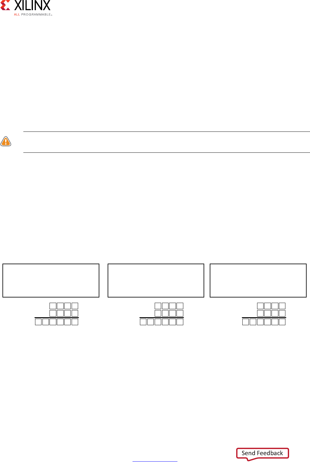
High-Level Synthesis 664
UG902 (v2017.1) April 5, 2017 www.xilinx.com
Chapter 4: High-Level Synthesis Reference Guide
SystemC bit-accurate data types:
• sc_[u]int
Default initialization to 0
•sc_big[u]int
Default initialization to 0
• sc_[u]fixed
Default initialization to 0
CAUTION! When migrating SystemC types to Vivado HLS types, be sure that no variables are read or
used in conditionals until they are written to.
SystemC designs can be started showing all outputs with a default value of zero, whether or
not the output has been written to. The same variables expressed as Vivado HLS types
remain unknown until written to.
Integer Division
When using integer division, Vivado HLS types are consistent with sc_big[u]int types
but behave differently than sc_[u]int types. The following figure shows an example.
The SystemC sc_int type returns a zero value when an unsigned integer is divided by a
negative signed integer. The Vivado HLS types, such as the SystemC sc_bigint type,
represent the negative result.
X-Ref Target - Figure 4-15
Figure 4-15: Integer Division Differences
#include “ap_int.h”
ap_uint<15>dividend = 32757;
ap_int<15>divisor = -2;
ap_int<21>ret = dividend/divisor;
ap_(u)int
dividend
divisor
ret
7 F F F
7 F F E
1 F C 0 0 1
/
32767
-2
-16383
#include “systemc.h”
sc_biguint<15>dividend = 32757;
sc_bigint<15>divisor = -2;
sc_bigint<21>ret = dividend/divisor;
sc_big(u)int
dividend
divisor
ret
7 F F F
7 F F E
1 F C 0 0 1
/
32767
-2
-16383
#include “systemc.h”
sc_uint<15>dividend = 32757;
sc_int<15>divisor = -2;
sc_int<21>ret = dividend/divisor;
sc_(u)int
dividend
divisor
ret
7 F F F
7 F F E
0 0 0 0 0 0
/
32767
-2
0
==
/
X14224
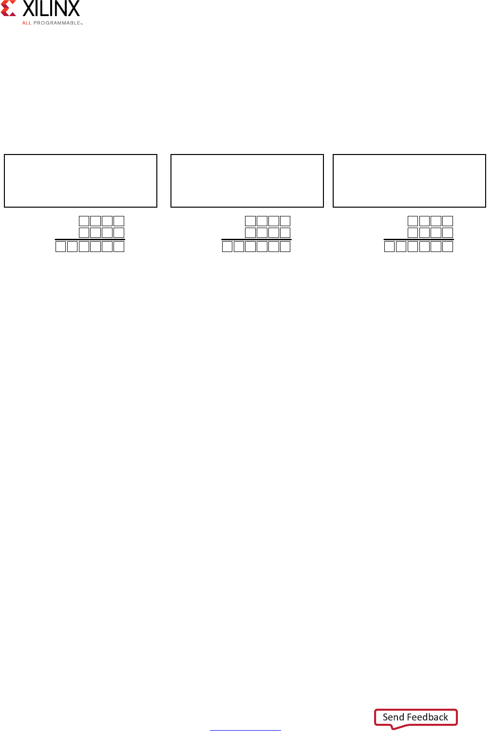
High-Level Synthesis 665
UG902 (v2017.1) April 5, 2017 www.xilinx.com
Chapter 4: High-Level Synthesis Reference Guide
Integer Modulus
When using the modulus operator, Vivado HLS types are consistent with sc_big[u]int
types, but behave differently than sc_[u]int types. The following figure shows an
example.
The SystemC sc_int type returns the value of the dividend of a modulus operation when:
• The dividend is an unsigned integer, and
• The divisor is a negative signed integer.
The Vivado HLS types (such as the SystemC sc_bigint type) returns the positive result of
the modulus operation.
Negative Shifts
When the value of a shift operation is a negative number, Vivado HLS ap_[u]int types
shift the value in the opposite direction. For example, it returns a left-shift for a right-shift
operation).
The SystemC types sc_[u]int and sc_big[u]int behave differently in this case. The
following figure shows an example of this operation for both Vivado HLS and SystemC
types.
X-Ref Target - Figure 4-16
Figure 4-16: Integer Modules Differences
#include “ap_int.h”
ap_uint<15>dividend = 18;
ap_int<15>divisor = -5;
ap_int<21>ret = dividend%divisor;
ap_(u)int
dividend
divisor
ret
0 0 1 2
7 F F B
0 0 0 0 0 3
%
18
-5
3
#include “systemc.h”
sc_biguint<15>dividend = 18;
sc_bigint<15>divisor = -5;
sc_bigint<21>ret = dividend%divisor;
sc_big(u)int
dividend
divisor
ret
0 0 1 2
7 F F B
0 0 0 0 0 3
%
18
-5
3
#include “systemc.h”
sc_uint<15>dividend = 18;
sc_int<15>divisor = -5;
sc_int<21>ret = dividend%divisor;
sc_(u)int
dividend
divisor
ret
0 0 1 2
7 F F B
0 0 0 0 1 2
%
18
-5
18
==
/
X14225
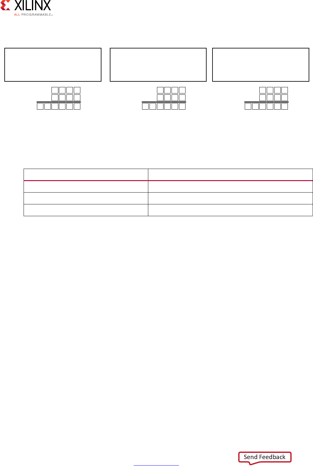
High-Level Synthesis 666
UG902 (v2017.1) April 5, 2017 www.xilinx.com
Chapter 4: High-Level Synthesis Reference Guide
The following table summarizes the negative shift differences.
Over-Shift Left
When a shift operation is performed and the result overflows the input variable but not the
output or assigned variable, Vivado HLS types and SystemC types behave differently.
•Vivado HLS ap_[u]int shifts the value and then assigns meaning to the upper bits
that are lost (or overflowed).
•Both SystemC sc_big(u)int and sc_(u)int types assign the result and then shift,
preserving the upper bits.
• The following figure shows an example of this operation for both Vivado HLS and
SystemC types.
X-Ref Target - Figure 4-17
Figure 4-17: Negative Shift Differences
X14226
#include “ap_int.h”
ap_uint<15>op = 24;
ap_int<15>shift = -2;
ap_int<21>ret = op>>shift;
ap_(u)int
op
shift
ret
0 0 1 8
7 F F E
0 0 0 0 6 0
>>
24
-2
96
#include “systemc.h”
sc_biguint<15>op = 24;
sc_bigint<15>shift = -2;
sc_bigint<21>ret = op>>shift;
sc_big(u)int
0 0 1 8
7 F F E
0 0 0 0 1 8
24
-2
24
#include “systemc.h”
sc_uint<15>op = 24;
sc_int<15>shift = -2;
sc_int<21>ret = op>>shift;
sc_(u)int
0 0 1 8
7 F F E
0 0 0 0 0 0
24
-2
0
=
/
=
/
op
shift
ret
>>
op
shift
ret
>>
Table 4-98: Negative Shift Differences Summary
Type Action
ap_[u]int Shifts in the opposite direction.
sc_[u]int Returns a zero
sc_big[u]int Does not shift
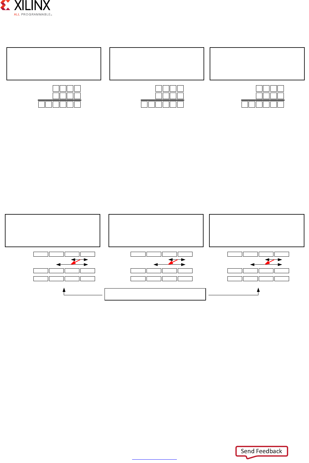
High-Level Synthesis 667
UG902 (v2017.1) April 5, 2017 www.xilinx.com
Chapter 4: High-Level Synthesis Reference Guide
Range Operation
There are differences in behavior when the range operation is used and the size of the
range is different between the source and destination. The following figure shows an
example of this operation for both Vivado HLS and SystemC types. See the summary below.
•Vivado HLS ap_[u]int types and SystemC sc_big[u]int types replace the
specified range and extend to fill the target range with zeros.
•SystemC sc_big[u]int types update only with the range of the source.
Division and Fixed-Point Types
When performing division with fixed-point type variables of different sizes, there is a
difference in how the fractional values are assigned between Vivado HLS types and SystemC
types.
X-Ref Target - Figure 4-18
Figure 4-18: Over-Shift Left Differences
#include “ap_int.h”
ap_uint<15>op = 0x7234;
ap_int<15>shift = 4;
ap_int<21>ret = op<<shift;
ap_(u)int
op
shift
ret
7 2 3 4
0 0 0 4
0 0 2 3 4 0
<<
29236
4
9024
#include “systemc.h”
sc_biguint<15>op = 0x7234;
sc_bigint<15>shift = 4;
sc_bigint<21>ret = op<<shift;
sc_big(u)int
7 2 3 4
0 0 0 4
0 7 2 3 4 0
29236
4
467776
#include “systemc.h”
sc_uint<15>op = 0x7234;
sc_int<15>shift = 4;
sc_int<21>ret = op<<shift;
sc_(u)int
7 2 3 4
0 0 0 4
0 7 2 3 4 0
29236
4
467776
==
/
op
shift
ret<<
op
shift
ret<<
X14227
X-Ref Target - Figure 4-19
Figure 4-19: Range Operation Differences
#include “systemc.h”
sc_uint<64>repl = 0xABCDEFLL;
sc_int<64>value = 0x12345678LL;
value.range(43,8)=repl.range(23,8);
ap_(u)int
repl
value
value
#include “systemc.h”
sc_uint<64>repl = 0xABCDEFLL;
sc_int<64>value = 0x12345678LL;
value.range(43,8)=repl.range(23,8);
sc_big(u)int
#include “systemc.h”
sc_uint<64>repl = 0xABCDEFLL;
sc_int<64>value = 0x12345678LL;
value.range(43,8)=repl.range(23,8);
sc_(u)int
=
/
=
/
0000 0000 00AB CDEF
0000 0000 1234 5678
0000 0000 00AB CD78
repl
value
value
0000 0000 00AB CDEF
0000 0000 1234 5678
0000 0000 12AB CD78
repl
value
value
0000 0000 00AB CDEF
0000 0000 1234 5678
0000 0000 00AB CD78
Types ap_(u)int and sc_(u)int behave the same
X14228
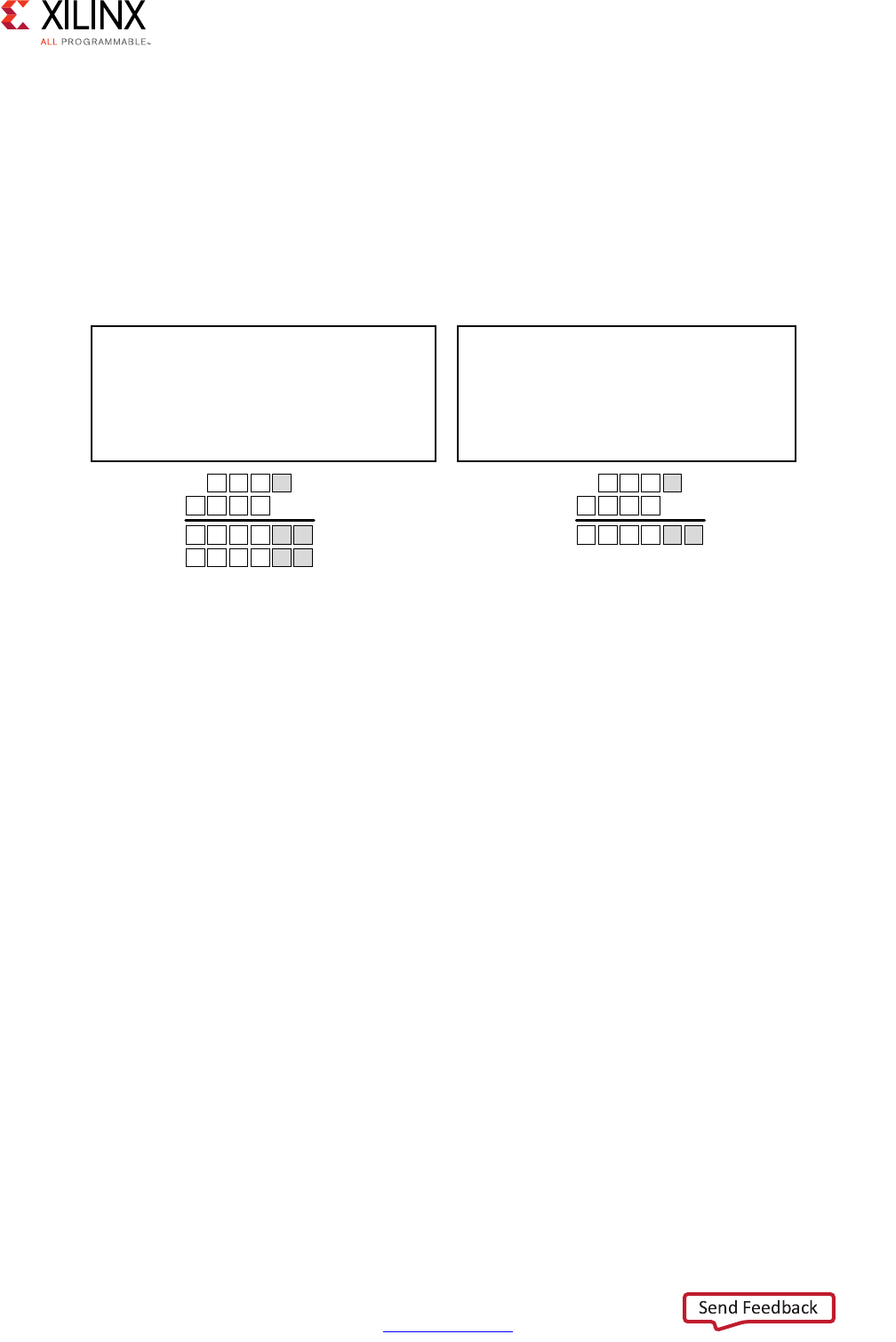
High-Level Synthesis 668
UG902 (v2017.1) April 5, 2017 www.xilinx.com
Chapter 4: High-Level Synthesis Reference Guide
For ap_[u]fixed types, the fraction is no greater than that of the dividend. SystemC
sc_[u]fixed types retain the fractional precision on divide. The fractional part can be
retained when using the ap_[u]fixed type by casting to the new variable width before
assignment.
The following figure shows an example of this operation for both Vivado HLS and SystemC
types.
Right Shift and Fixed-Point Types
Vivado HLS and SystemC behave differently when a right-shift operation is performed
• With Vivado HLS fixed-point types, the shift is performed and then the value is
assigned.
• With SystemC fixed-point types, the value is assigned and then the shift is performed.
When the result is a fixed-point type with more fractional bits, the SystemC type preserves
the additional accuracy.
The following figure shows an example of this operation for both Vivado HLS and SystemC
types.
X-Ref Target - Figure 4-20
Figure 4-20: Fixed-Point Division Differences
#include “ap_fixed.h”
ap_fixed<3,3> dividend=2;
ap_fixed<4,4> divisor=4;
ap_fixed<4,2> ret=dividend/divisor;
//casting required to keep precision
ap_fixed<4,2> ret2=ap_fixed<4,2>(dividend)/divisor;
ap_(u)fixed
0 0 0 0 0 0
sc_(u)fixed
dividend
divisor
ret
ret2
=
/
0 0 0 0 1 0
0 1 0 0
0 1 0 0
2.0
4.0
0
0.5
000010
dividend
divisor
ret
0 1 0 0
0 1 0 0
2.0
4.0
0.5
#include “systemc.h”
#define SC_INCLUDE_FX
sc_fixed<3,3> dividend=2;
sc_fixed<4,4> divisor=4;
sc_fixed<4,2> ret=dividend/divisor;
X14229
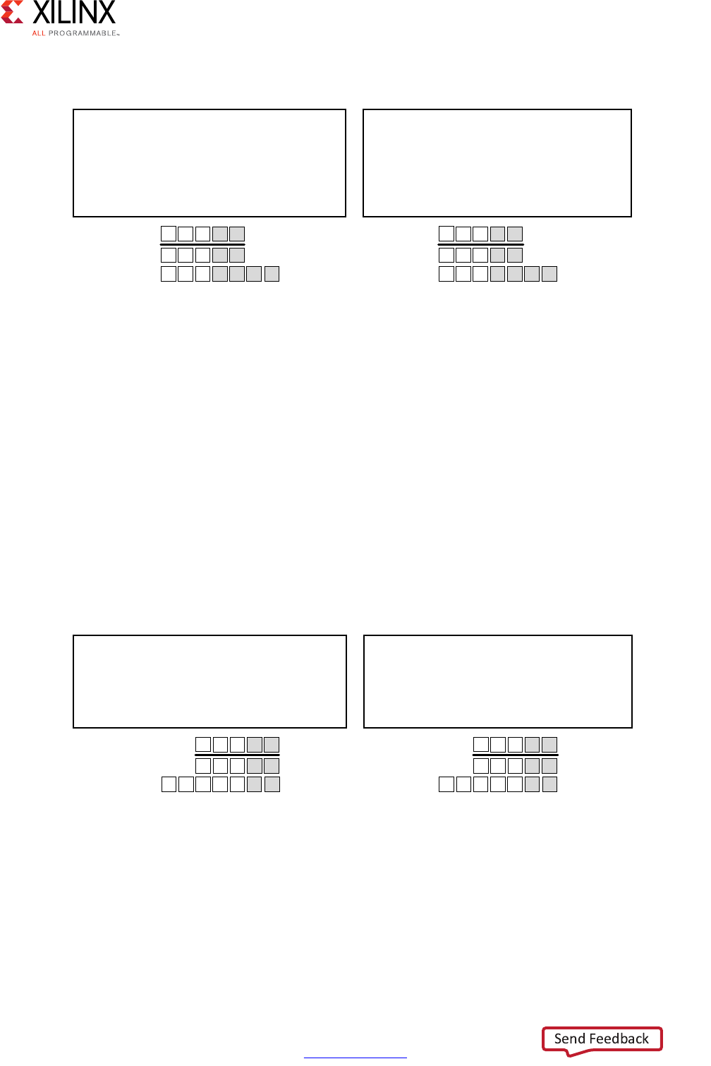
High-Level Synthesis 669
UG902 (v2017.1) April 5, 2017 www.xilinx.com
Chapter 4: High-Level Synthesis Reference Guide
The type of quantization mode does not affect the result of the ap_[u]fixed right-shift. Xilinx
recommends that you assign to the size of the result type before the shift operation.
Left Shift and Fixed-Point Types
When performing a left-shift operation with ap_[u]fixed types, the operand is
sign-extended, then shifted and then assigned. The SystemC sc_[u]fixed types assign
and then shift. In this case, the Vivado HLS types preserve any sign-intention.
The following figure shows an example of this operation for both Vivado HLS and SystemC
types.
X-Ref Target - Figure 4-21
Figure 4-21: Fixed-Point Differences with Right-Shift
#include “ap_fixed.h”
ap_fixed<5,3,AP_RND,AP_SAT> val=3.75
ap_fixed<5,3,AP_RND,AP_SAT> res=val>>2;
ap_fixed<7,3,AP_RND,AP_SAT> res2=val>>2;
ap_(u)fixed sc_(u)fixed
=
/
#include “systemc.h”
#define SC_INCLUDE_FX
sc_fixed<5,3 AP_RND,AP_SAT> val=3.75
sc_fixed<5,3,AP_RND,AP_SAT> res=val>>2;
sc_fixed<7,3,AP_RND,AP_SAT> res2=val>>2;
0 0 0 1 1 0
val
res
res2
1 1 1 1
0 0 0 1
3.75
0.75
0.75
0
1
0 0 0 0 1 1 1
val
res
res2
1 1 1 1
0 0 0 1
3.75
0.75
0.9375
0
1
1
X14230
X-Ref Target - Figure 4-22
Figure 4-22: Fixed-Point Differences with Left-Shift
#include “ap_fixed.h”
ap_fixed<5,3,AP_RND,AP_SAT> val=3.75
ap_fixed<5,3,AP_RND,AP_SAT> res=val<<2;
ap_fixed<7,5,AP_RND,AP_SAT> res2=val<<2;
ap_(u)fixed sc_(u)fixed
=
/
#include “systemc.h”
#define SC_INCLUDE_FX
ap_fixed<5,3,AP_RND,AP_SAT> val=3.75
ap_fixed<5,3,AP_RND,AP_SAT> res=val<<2;
ap_fixed<7,5,AP_RND,AP_SAT> res2=val<<2;
1 1 1 1 1 0
val
res
res2
1111
1 1 1 0
3.75
-1
-1
0
0
0 0 1 1 1 1 0
val
res
res2
1111
0111
3.75
3.75
15
0
1
0
X14231

High-Level Synthesis 670
UG902 (v2017.1) April 5, 2017 www.xilinx.com
Appendix A
Additional Resources and Legal Notices
Xilinx Resources
For support resources such as Answers, Documentation, Downloads, and Forums, see Xilinx
Support.
Solution Centers
See the Xilinx Solution Centers for support on devices, software tools, and intellectual
property at all stages of the design cycle. Topics include design assistance, advisories, and
troubleshooting tips.
Documentation Navigator and Design Hubs
Xilinx Documentation Navigator provides access to Xilinx documents, videos, and support
resources, which you can filter and search to find information. To open the Xilinx
Documentation Navigator (DocNav):
• From the Vivado IDE, select Help > Documentation and Tutorials.
• On Windows, select Start > All Programs > Xilinx Design Tools > DocNav.
• At the Linux command prompt, enter docnav.
Xilinx Design Hubs provide links to documentation organized by design tasks and other
topics, which you can use to learn key concepts and address frequently asked questions. To
access the Design Hubs:
• In the Xilinx Documentation Navigator, click the Design Hubs View tab.
• On the Xilinx website, see the Design Hubs page.
Note: For more information on Documentation Navigator, see the Documentation Navigator page
on the Xilinx website.
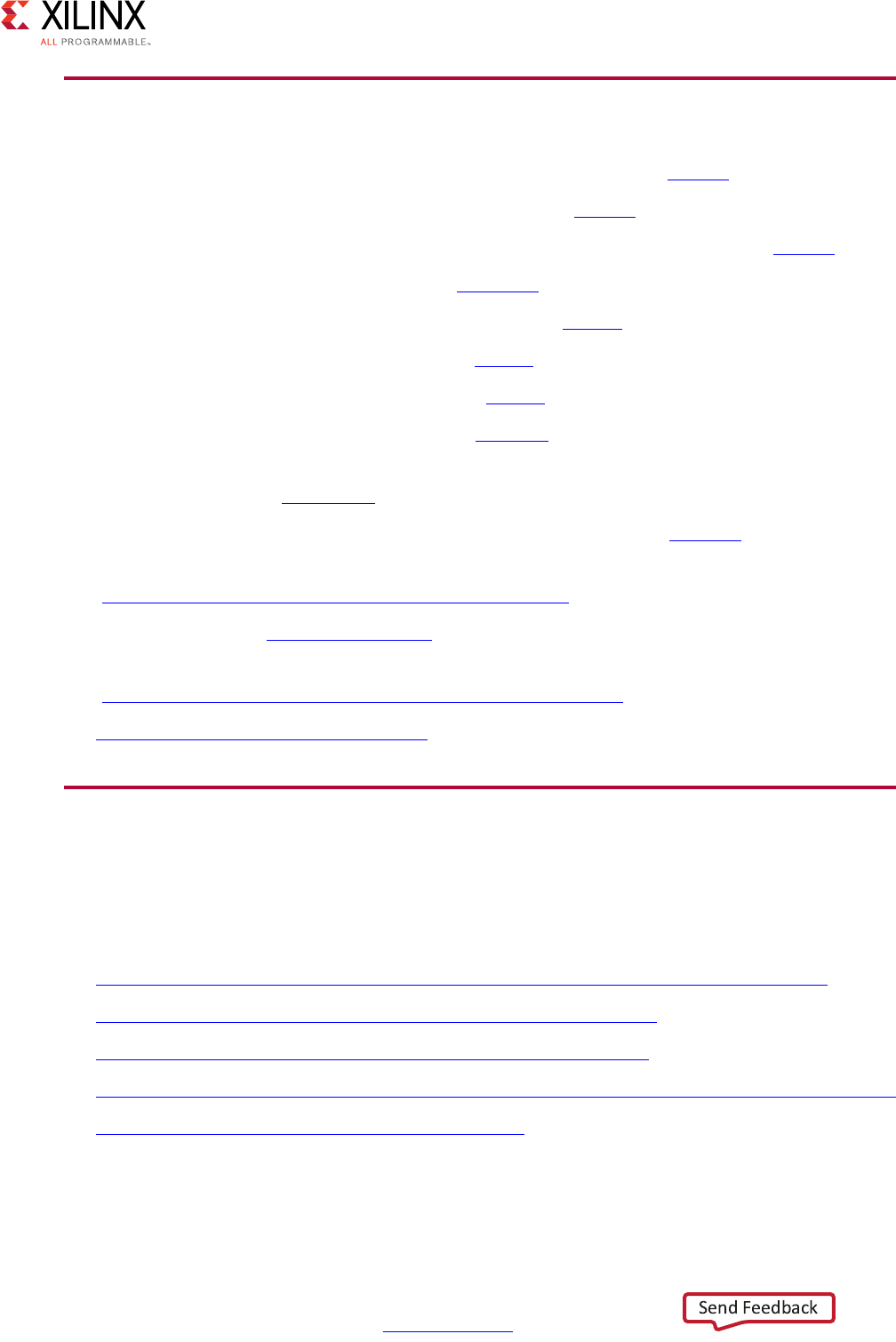
High-Level Synthesis 671
UG902 (v2017.1) April 5, 2017 www.xilinx.com
Appendix A: Additional Resources and Legal Notices
References
1. Introduction to FPGA Design with Vivado High-Level Synthesis (UG998)
2. Vivado® Design Suite Tutorial: High-Level Synthesis (UG871)
3. Vivado Design Suite User Guide: Release Notes, Installation, and Licensing (UG973)
4. Floating-Point Design with Vivado HLS (XAPP599)
5. LogiCORE IP Fast Fourier Transform Product Guide (PG109)
6. LogiCORE IP FIR Compiler Product Guide (PG149)
7. LogiCORE IP DDS Compiler Product Guide (PG141)
8. Vivado Design Suite AXI Reference Guide (UG1037)
9. Accelerating OpenCV Applications with Zynq-7000 All Programmable SoC Using Vivado
HLS Video Libraries (XAPP1167)
10. UltraFast™ High-Level Productivity Design Methodology Guide (UG1197)
11. Option Summary page on the GCC website
(gcc.gnu.org/onlinedocs/gcc/Option-Summary.html)
12. Accellera website (www.accellera.org)
13. AWGN page on the MathWorks website
(www.mathworks.com/help/comm/ug/awgn-channel.html)
14. Vivado Design Suite Documentation
Training Resources
Xilinx provides a variety of training courses and QuickTake videos to help you learn more
about the concepts presented in this document. Use these links to explore related training
resources:
1. C-based Design: High-Level Synthesis with the Vivado HLS Tool Training Course
2. C-based HLS Coding for Hardware Designers Training Course
3. C-based HLS Coding for Software Designers Training Course
4. Vivado Design Suite QuickTake Video: Getting Started with Vivado High-Level Synthesis
5. Vivado Design Suite QuickTake Video Tutorials

High-Level Synthesis 672
UG902 (v2017.1) April 5, 2017 www.xilinx.com
Appendix A: Additional Resources and Legal Notices
Please Read: Important Legal Notices
The information disclosed to you hereunder (the “Materials”) is provided solely for the selection and use of Xilinx products. To the
maximum extent permitted by applicable law: (1) Materials are made available "AS IS" and with all faults, Xilinx hereby DISCLAIMS
ALL WARRANTIES AND CONDITIONS, EXPRESS, IMPLIED, OR STATUTORY, INCLUDING BUT NOT LIMITED TO WARRANTIES OF
MERCHANTABILITY, NON-INFRINGEMENT, OR FITNESS FOR ANY PARTICULAR PURPOSE; and (2) Xilinx shall not be liable (whether
in contract or tort, including negligence, or under any other theory of liability) for any loss or damage of any kind or nature related
to, arising under, or in connection with, the Materials (including your use of the Materials), including for any direct, indirect, special,
incidental, or consequential loss or damage (including loss of data, profits, goodwill, or any type of loss or damage suffered as a
result of any action brought by a third party) even if such damage or loss was reasonably foreseeable or Xilinx had been advised
of the possibility of the same. Xilinx assumes no obligation to correct any errors contained in the Materials or to notify you of
updates to the Materials or to product specifications. You may not reproduce, modify, distribute, or publicly display the Materials
without prior written consent. Certain products are subject to the terms and conditions of Xilinx’s limited warranty, please refer to
Xilinx’s Terms of Sale which can be viewed at https://www.xilinx.com/legal.htm#tos; IP cores may be subject to warranty and
support terms contained in a license issued to you by Xilinx. Xilinx products are not designed or intended to be fail-safe or for use
in any application requiring fail-safe performance; you assume sole risk and liability for use of Xilinx products in such critical
applications, please refer to Xilinx’s Terms of Sale which can be viewed at https://www.xilinx.com/legal.htm#tos.
AUTOMOTIVE APPLICATIONS DISCLAIMER
AUTOMOTIVE PRODUCTS (IDENTIFIED AS “XA” IN THE PART NUMBER) ARE NOT WARRANTED FOR USE IN THE DEPLOYMENT OF
AIRBAGS OR FOR USE IN APPLICATIONS THAT AFFECT CONTROL OF A VEHICLE (“SAFETY APPLICATION”) UNLESS THERE IS A
SAFETY CONCEPT OR REDUNDANCY FEATURE CONSISTENT WITH THE ISO 26262 AUTOMOTIVE SAFETY STANDARD (“SAFETY
DESIGN”). CUSTOMER SHALL, PRIOR TO USING OR DISTRIBUTING ANY SYSTEMS THAT INCORPORATE PRODUCTS, THOROUGHLY
TEST SUCH SYSTEMS FOR SAFETY PURPOSES. USE OF PRODUCTS IN A SAFETY APPLICATION WITHOUT A SAFETY DESIGN IS FULLY
AT THE RISK OF CUSTOMER, SUBJECT ONLY TO APPLICABLE LAWS AND REGULATIONS GOVERNING LIMITATIONS ON PRODUCT
LIABILITY.
© Copyright 2012-2017 Xilinx, Inc. Xilinx, the Xilinx logo, Artix, ISE, Kintex, Spartan, Virtex, Vivado, Zynq, and other designated
brands included herein are trademarks of Xilinx in the United States and other countries. OpenCL and the OpenCL logo are
trademarks of Apple Inc. used by permission by Khronos. All other trademarks are the property of their respective owners.
