Yoshimi User Manual
User Manual:
Open the PDF directly: View PDF ![]() .
.
Page Count: 282 [warning: Documents this large are best viewed by clicking the View PDF Link!]
- 1 Introduction
- 2 Configuration Files
- 2.1 Configuration Files / Patch Set
- 2.2 Configuration Files / Config
- 2.3 Configuration Files / State
- 2.4 Configuration Files / Instrument
- 2.5 Configuration Files / Scale
- 2.6 Configuration Files / Presets
- 2.7 Configuration Files / Instance
- 2.8 Configuration Files / History
- 2.9 Configuration Files / Banks
- 2.10 Configuration Files / .bankdir
- 2.11 Configuration Files / Windows
- 2.12 Configuration Files / Format
- 2.13 Configuration Files / MIDI Learn
- 3 Banks and Roots
- 4 Menu
- 4.1 Menu / Yoshimi
- 4.2 Menu / Instruments
- 4.3 Menu / Patch Sets
- 4.4 Menu / Paths
- 4.5 Menu / Scales
- 4.6 Menu / State
- 5 Scales
- 6 Stock Settings Elements
- 7 Top Panel
- 8 Effects
- 9 Bottom Panel
- 10 ADDsynth
- 10.1 ADDsynth / AMPLITUDE
- 10.2 ADDsynth / FILTER
- 10.3 ADDsynth / FREQUENCY
- 10.4 ADDsynth / Voice Parameters
- 10.5 ADDsynth / Voice List
- 10.6 ADDsynth / Oscillator
- 10.7 ADDsynth / Resonance
- 11 PADsynth
- 11.1 PADsynth / Algorithm
- 11.2 PADsynth / Harmonic Structure
- 11.3 PADsynth / Envelopes and LFOs
- 12 SUBsynth
- 13 Kit Edit
- 14 Banks Collection
- 15 Non-Registered Parameter Numbers
- 16 Vector Control
- 17 MIDI Learn
- 18 The Yoshimi Command-Line Interface
- 18.1 Command Depth
- 18.2 Command Level
- 18.3 Command Scripts
- 18.4 Other Command Tables
- 18.5 MLearn
- 18.6 EFfects Commands
- 18.7 List / History [s]
- 18.8 Command Descriptions
- 18.9 Direct Access
- 19 LV2 Plug-in Support
- 20 Yoshimi Man Page
- 21 Concepts
- 21.1 Concepts / Terms
- 21.2 Concepts / ALSA Versus JACK
- 21.3 Concepts / Banks and Roots
- 21.4 Concepts / Basic Synthesis
- 21.4.1 Concepts / Basic Synthesis / Panning
- 21.4.2 Concepts / Basic Synthesis / Wetness
- 21.4.3 Concepts / Basic Synthesis / Single Note
- 21.4.4 Concepts / Basic Synthesis / Harmonics
- 21.4.5 Concepts / Basic Synthesis / Randomness
- 21.4.6 Concepts / Basic Synthesis / Components
- 21.4.7 Concepts / Basic Synthesis / Filters
- 21.4.8 Concepts / Basic Synthesis / Envelopes
- 21.4.9 Concepts / Basic Synthesis / Formants
- 21.5 Concepts / MIDI
- 21.6 Concepts / Instances
- 21.7 Concepts / Command Line
- 21.8 Concepts / LV2 Plugin
- 21.9 Concepts / Numbering
- 22 Building Yoshimi
- 23 Summary
- 24 References
Yoshimi Advanced User Manual, v 1.5.10
Chris Ahlstrom (ahlstromcj@gmail.com) with Will J. Godfrey
December 29, 2018
1

Yoshimi Software Synthesizer User Manual
Contents
1 Introduction 13
1.1 Yoshimi And ZynAddSubFX .................................. 13
1.2 New Features ........................................... 13
1.2.1 MIDI Learn ........................................ 13
1.2.2 LV2 Plugin ........................................ 14
1.2.3 Control Automation ................................... 14
1.2.4 MIDI CC ......................................... 14
1.2.5 Vectors .......................................... 15
1.2.6 Bank Support ....................................... 15
1.2.7 Accessibility ........................................ 15
1.2.8 Command Line ...................................... 16
1.2.9 Audio Support ...................................... 17
1.2.10 Miscellany ......................................... 17
1.3 Document Structure ....................................... 18
1.4 Yoshimi Mailing List ....................................... 18
1.5 Yoshimi Licensing ........................................ 19
1.6 Let’s Get Started with Yoshimi! ................................. 19
2 Configuration Files 22
2.1 Configuration Files / Patch Set ................................. 24
2.2 Configuration Files / Config ................................... 24
2.3 Configuration Files / State ................................... 25
2.4 Configuration Files / Instrument ................................ 26
2.5 Configuration Files / Scale ................................... 26
2.6 Configuration Files / Presets .................................. 26
2.7 Configuration Files / Instance .................................. 26
2.8 Configuration Files / History .................................. 26
2.9 Configuration Files / Banks ................................... 27
2.10 Configuration Files / .bankdir .................................. 28
2.11 Configuration Files / Windows ................................. 28
2.12 Configuration Files / Format .................................. 28
2.13 Configuration Files / MIDI Learn ................................ 29
3 Banks and Roots 29
3.1 Roots ............................................... 30
3.2 Banks ............................................... 31
3.2.1 Bank Directories ..................................... 31
4 Menu 31
4.1 Menu / Yoshimi ......................................... 31
4.1.1 Menu / Yoshimi / About... ............................... 32
4.1.2 Menu / Yoshimi / New instance ............................ 33
4.1.3 Menu / Yoshimi / Settings... .............................. 34
4.1.3.1 Menu / Yoshimi / Settings / Main Settings ................. 34
4.1.3.2 Menu / Yoshimi / Settings / Switches .................... 39
4.1.3.3 Menu / Yoshimi / Settings / Jack ...................... 40
2

Yoshimi Software Synthesizer User Manual
4.1.3.4 Menu / Yoshimi / Settings / Alsa ...................... 42
4.1.3.5 Menu / Yoshimi / Settings / MIDI ..................... 44
4.1.4 Menu / Yoshimi / MIDI Learn... ............................ 46
4.1.5 Menu / Yoshimi / View Manual... ........................... 46
4.1.6 Menu / Yoshimi / Exit ................................. 46
4.2 Menu / Instruments ....................................... 47
4.2.1 Menu / Instrument / Show Stored... .......................... 48
4.2.2 Menu / Instrument / Load External... ......................... 52
4.2.3 Menu / Instrument / Save External... ......................... 55
4.2.4 Menu / Instrument / Recent Instruments... ...................... 56
4.2.5 Menu / Instrument / Clear ............................... 56
4.2.6 Menu / Instrument / Misc Notes ............................ 56
4.3 Menu / Patch Sets ........................................ 57
4.3.1 Menu / Patch Sets / Show Patch Banks... ....................... 57
4.3.2 Menu / Patch Sets / Load External... ......................... 59
4.3.3 Menu / Patch Sets / Save External... .......................... 59
4.3.4 Menu / Patch Sets / Recent Sets ............................ 60
4.3.5 Menu / Patch Sets / Patch Bank Roots ........................ 60
4.4 Menu / Paths ........................................... 62
4.5 Menu / Scales ........................................... 63
4.6 Menu / State ........................................... 64
5 Scales 65
5.1 Scales / Command Line ..................................... 65
5.2 Scales / Show Settings ...................................... 67
5.2.1 Scales Basic Settings ................................... 67
5.2.2 Keyboard Mapping .................................... 70
5.3 Scales / Load ........................................... 71
5.4 Scales / Save ........................................... 71
5.5 Scales / Recent Scales... ..................................... 71
5.6 Scales / Clear ........................................... 72
6 Stock Settings Elements 72
6.1 Settings Features ......................................... 72
6.1.1 Mouse Features ...................................... 72
6.1.2 Tooltips .......................................... 72
6.1.3 Title Bars ......................................... 73
6.1.4 Color Coding ....................................... 73
6.1.5 Rotary Knobs ....................................... 73
6.1.6 Sliders ........................................... 73
6.1.7 Presets .......................................... 74
6.1.8 Automation ........................................ 74
6.2 Filter Settings ........................................... 75
6.2.1 Filter Type ........................................ 75
6.2.2 Filter Cutoff ....................................... 76
6.2.3 Filter Resonance ..................................... 76
6.2.4 Filter Stages ....................................... 77
6.2.5 Filter Parameters User Interface ............................ 78
3

Yoshimi Software Synthesizer User Manual
6.3 Stock Resonance Settings .................................... 80
6.4 LFO Settings ........................................... 83
6.4.1 LFO Basic Parameters .................................. 84
6.4.2 LFO Function ....................................... 84
6.4.3 LFO Randomness .................................... 85
6.4.4 LFO, More Settings ................................... 85
6.4.5 LFO User Interface Panels ................................ 85
6.4.6 Filter LFO Sub-panel .................................. 87
6.4.7 Frequency LFO Sub-panel ................................ 88
6.5 Envelope Settings ......................................... 88
6.5.1 Amplitude Envelope Sub-Panel ............................. 89
6.5.2 Envelope Settings .................................... 90
6.5.3 Freemode Envelope Settings ............................... 91
6.5.4 Envelope Settings, Frequency .............................. 93
6.5.5 Envelope Settings for Filter ............................... 94
6.5.6 Formant Filter Settings ................................. 95
6.5.6.1 Formant Parameters .............................. 96
6.5.6.2 Formant Vowel Parameters .......................... 97
6.5.6.3 Formant Sequence Parameters ........................ 97
6.6 Clipboard Presets ......................................... 98
6.6.1 Clipboard/Preset Copy ................................. 98
6.6.2 Clipboard/Preset Paste ................................. 99
7 Top Panel 100
7.1 Mixer Panel Window ....................................... 101
7.2 Virtual Keyboard ......................................... 104
7.2.1 Virtual Keyboard, Basics ................................ 105
7.2.2 Virtual Keyboard, ASCII Mapping ........................... 106
7.2.3 Virtual Keyboard, Controllers .............................. 106
8 Effects 107
8.1 Effects / Panel Types ...................................... 108
8.1.1 Effects / Panel Types / System ............................ 111
8.1.2 Effects / Panel Types / Insertion ........................... 112
8.1.3 Effects / Panel Types / Instrument .......................... 113
8.2 Effects / None .......................................... 114
8.3 Effects / DynFilter ........................................ 114
8.3.1 Effects / DynFilter / Circuit .............................. 114
8.3.2 Effects / DynFilter / User Interface .......................... 115
8.3.3 Effects / DynFilter / NRPN Values .......................... 117
8.4 Effects / AlienWah ........................................ 117
8.4.1 Effects / AlienWah / Circuit .............................. 117
8.4.2 Effects / AlienWah / User Interface .......................... 118
8.4.3 Effects / AlienWah / NRPN Values .......................... 119
8.5 Effects / Chorus ......................................... 119
8.5.1 Effects / Chorus / Circuit ................................ 120
8.5.2 Effects / Chorus / User Interface ............................ 121
8.5.3 Effects / Chorus / NRPN Values ............................ 121
4

Yoshimi Software Synthesizer User Manual
8.6 Effects / Distortion ........................................ 122
8.6.1 Effects / Distortion / Circuit .............................. 122
8.6.2 Effects / Distortion / User Interface .......................... 123
8.6.3 Effects / Distortion / NRPN Values .......................... 124
8.7 Effects / Echo ........................................... 124
8.7.1 Effects / Echo / Circuit ................................. 124
8.7.2 Effects / Echo / User Interface ............................. 124
8.7.3 Effects / Echo / NRPN Values ............................. 125
8.8 Effects / EQ ........................................... 125
8.8.1 Effects / EQ / Circuit .................................. 125
8.8.2 Effects / EQ / User Interface .............................. 125
8.8.3 Effects / EQ / NRPN Values .............................. 126
8.9 Effects / Phaser .......................................... 127
8.9.1 Effects / Phaser / Circuit ................................ 127
8.9.2 Effects / Phaser / User Interface ............................ 128
8.9.3 Effects / Phaser / NRPN Values ............................ 130
8.10 Effects / Reverb ......................................... 130
8.10.1 Effects / Reverb / Circuit ................................ 130
8.10.2 Effects / Reverb / User Interface ............................ 130
8.10.3 Effects / Reverb / NRPN Values ............................ 133
9 Bottom Panel 133
9.1 Bottom Panel Controls ...................................... 133
9.1.0.1 Tip: Using the VU Meter ........................... 137
9.2 Bottom Panel / Controllers ................................... 138
9.2.1 Bottom Panel / Controllers / MIDI Controls ..................... 139
9.2.2 Bottom Panel / Controllers / Resonance ........................ 140
9.2.3 Bottom Panel / Controllers / Portamento ....................... 140
9.3 Bottom Panel Instrument Edit ................................. 141
10 ADDsynth 143
10.1 ADDsynth / AMPLITUDE ................................... 145
10.2 ADDsynth / FILTER ...................................... 147
10.3 ADDsynth / FREQUENCY ................................... 147
10.4 ADDsynth / Voice Parameters ................................. 148
10.4.1 ADDsynth / Voice Parameters / AMPLITUDE .................... 150
10.4.2 ADDsynth / Voice Parameters / FILTER ....................... 151
10.4.3 ADDsynth / Voice Parameters / FREQUENCY ................... 151
10.4.4 ADDsynth / Voice Parameters / UNISON ....................... 152
10.4.5 ADDsynth / Voice Parameters / Voice Oscillator ................... 153
10.4.6 ADDsynth / Voice Parameters / MODULATOR ................... 155
10.4.6.1 Tip: Using the Ring Modulator ........................ 157
10.5 ADDsynth / Voice List ...................................... 157
10.6 ADDsynth / Oscillator ...................................... 159
10.7 ADDsynth / Resonance ..................................... 160
5

Yoshimi Software Synthesizer User Manual
11 PADsynth 160
11.1 PADsynth / Algorithm ...................................... 160
11.1.1 PADsynth / Algorithm / General ............................ 161
11.1.2 PADsynth / Algorithm / Harmonic Bandwidth .................... 161
11.1.2.1 Tip: Using the PADsynth ........................... 162
11.2 PADsynth / Harmonic Structure ................................ 163
11.2.1 PADsynth / Harmonic Structure / Basics ....................... 164
11.2.2 PADsynth / Harmonic Structure / Harmonic ..................... 165
11.2.3 PADsynth / Harmonic Structure / Bandwidth and Position ............. 167
11.2.4 PADsynth / Harmonic Structure / Export ....................... 169
11.2.5 PADsynth / Harmonic Structure / Resonance ..................... 169
11.2.6 PADsynth / Harmonic Structure / Change ...................... 169
11.2.6.1 PADsynth / Harmonic Structure / Change / Oscillator .......... 170
11.2.6.2 PADsynth / Harmonic Structure / Change / Base Function ........ 171
11.2.6.3 PADsynth / Harmonic Structure / Change / Middle ............ 172
11.2.6.4 PADsynth / Harmonic Structure / Change / Harmonic .......... 175
11.3 PADsynth / Envelopes and LFOs ................................ 176
12 SUBsynth 178
12.1 SUBsynth / AMPLITUDE ................................... 179
12.2 SUBsynth / BANDWIDTH ................................... 179
12.3 SUBsynth / FREQUENCY ................................... 180
12.4 SUBsynth / OVERTONES ................................... 181
12.5 SUBsynth / FILTER ....................................... 182
12.6 SUBsynth / Harmonics ..................................... 182
13 Kit Edit 183
14 Banks Collection 186
14.1 Yoshimi Banks .......................................... 186
14.2 Additional ZynAddSubFX Banks ................................ 187
14.3 Additional Banks ......................................... 187
15 Non-Registered Parameter Numbers 188
15.1 NRPN / Basics .......................................... 188
15.2 NRPN / Effects Control ..................................... 190
15.2.0.1 Reverb ..................................... 190
15.2.0.2 Echo ...................................... 190
15.2.0.3 Chorus ..................................... 190
15.2.0.4 Phaser ..................................... 191
15.2.0.5 AlienWah .................................... 191
15.2.0.6 Distortion .................................... 191
15.2.0.7 EQ ....................................... 191
15.2.0.8 DynFilter .................................... 192
15.2.0.9 Yoshimi Extensions .............................. 192
15.3 NRPN / Dynamic System Settings ............................... 193
6

Yoshimi Software Synthesizer User Manual
16 Vector Control 194
16.1 Vector / Basics .......................................... 194
16.2 Vector Dialogs .......................................... 195
16.3 Vector / Vector Control ..................................... 200
16.4 Vector / Command Line ..................................... 201
17 MIDI Learn 203
17.1 MIDI Learn / Basics ....................................... 203
17.2 MIDI Learn / User Interface .................................. 204
17.3 MIDI Learn / Tutorial ...................................... 209
18 The Yoshimi Command-Line Interface 209
18.1 Command Depth ......................................... 210
18.2 Command Level ......................................... 213
18.3 Command Scripts ......................................... 213
18.4 Other Command Tables ..................................... 215
18.4.1 Top Commands ...................................... 215
18.4.1.1 SOlo ....................................... 217
18.4.1.2 Set / Read / MLearn Context Levels .................... 217
18.4.1.3 Part Command Level ............................. 217
18.4.2 Part Common Commands ................................ 218
18.4.3 Part Commands ..................................... 220
18.4.3.1 Part AddSynth Commands .......................... 221
18.4.3.2 Part PadSynth Commands .......................... 222
18.4.3.3 Part SubSynth Commands .......................... 223
18.4.3.4 Resonance Commands ............................. 223
18.4.3.5 Part Waveform Commands .......................... 224
18.4.4 Engine Envelopes ..................................... 225
18.4.5 Engine Filters ....................................... 226
18.4.6 Engine LFOs ....................................... 227
18.5 MLearn .............................................. 228
18.6 EFfects Commands ........................................ 228
18.6.1 Vector Commands .................................... 233
18.6.2 Scales Commands .................................... 234
18.6.3 Help List ......................................... 235
18.7 List / History [s] ......................................... 235
18.7.1 Load/Save List ...................................... 236
18.7.2 Config Commands .................................... 237
18.8 Command Descriptions ..................................... 239
18.9 Direct Access ........................................... 242
19 LV2 Plug-in Support 244
20 Yoshimi Man Page 245
7

Yoshimi Software Synthesizer User Manual
21 Concepts 247
21.1 Concepts / Terms ........................................ 247
21.1.1 Concepts / Terms / Cent ................................ 247
21.1.2 Concepts / Terms / Frame ............................... 247
21.1.3 Concepts / Terms / Instrument ............................. 247
21.1.4 Concepts / Terms / Part ................................ 247
21.1.5 Concepts / Terms / Patch ................................ 248
21.1.6 Concepts / Terms / Patch Set ............................. 248
21.1.7 Concepts / Terms / Presets ............................... 248
21.1.8 Concepts / Terms / Program .............................. 248
21.1.9 Concepts / Terms / Voice ................................ 248
21.2 Concepts / ALSA Versus JACK ................................ 249
21.3 Concepts / Banks and Roots .................................. 249
21.4 Concepts / Basic Synthesis ................................... 250
21.4.1 Concepts / Basic Synthesis / Panning ......................... 250
21.4.2 Concepts / Basic Synthesis / Wetness ......................... 251
21.4.3 Concepts / Basic Synthesis / Single Note ....................... 251
21.4.4 Concepts / Basic Synthesis / Harmonics ........................ 251
21.4.4.1 Harmonic Bandwidth ............................. 252
21.4.4.2 Harmonic Amplitude ............................. 252
21.4.5 Concepts / Basic Synthesis / Randomness ....................... 253
21.4.6 Concepts / Basic Synthesis / Components ....................... 253
21.4.7 Concepts / Basic Synthesis / Filters .......................... 254
21.4.8 Concepts / Basic Synthesis / Envelopes ........................ 254
21.4.9 Concepts / Basic Synthesis / Formants ........................ 254
21.5 Concepts / MIDI ......................................... 255
21.5.1 Concepts / MIDI / Learn ................................ 255
21.5.2 Concepts / MIDI / Messages .............................. 255
21.5.3 Concepts / MIDI / NRPN ................................ 256
21.5.3.1 Concepts / MIDI / NRPN / Vector Control ................ 257
21.5.3.2 Concepts / MIDI / NRPN / Effects Control ................ 257
21.6 Concepts / Instances ....................................... 257
21.7 Concepts / Command Line ................................... 258
21.7.1 Concepts / Command Line / level ........................... 258
21.8 Concepts / LV2 Plugin ...................................... 258
21.9 Concepts / Numbering ...................................... 258
22 Building Yoshimi 258
22.1 Yoshimi Source Code ....................................... 259
22.2 Yoshimi Dependencies ...................................... 259
22.3 Build It .............................................. 260
22.4 Yoshimi Code Policies ...................................... 262
23 Summary 262
24 References 263
8

Yoshimi Software Synthesizer User Manual
List of Figures
1 Yoshimi Splash Screen! ...................................... 20
2 Yoshimi Main Screen ....................................... 21
3 Space Bar Prompt ........................................ 21
4 Configuration Warning Dialog .................................. 22
5 Yoshimi Menu, Exit ....................................... 32
6 Yoshimi Menu, About Dialog .................................. 32
7 Yoshimi Menu, Contributors ................................... 33
8 Yoshimi Main Settings Tab ................................... 35
9 OscilSize Values .......................................... 35
10 Internal Size Values ....................................... 36
11 PADSynth Interpolation ..................................... 36
12 QWERTY Virtual Keyboard Layout .............................. 36
13 Virtual Keyboard Layout .................................... 37
14 Send Reports ........................................... 37
15 Yoshimi Console Window .................................... 38
16 Yoshimi Font for Extended File Format ............................ 38
17 Yoshimi Switches Tab ...................................... 39
18 JACK Settings .......................................... 41
19 ALSA Settings .......................................... 43
20 MIDI Preferences ......................................... 44
21 MIDI Settings Pending ...................................... 44
22 MIDI Setting In Use ....................................... 45
23 Yoshimi Menu, Exit ....................................... 47
24 Yoshimi Menu, Instruments ................................... 47
25 Show Stored Instruments .................................... 48
26 A Sample Bank List ....................................... 50
27 Instruments, Load External ................................... 53
28 Manage Favorites Drop-Down List ............................... 54
29 Manage Favorites Dialog ..................................... 54
30 Instruments, Save External ................................... 55
31 Clear Instrument Dialog ..................................... 56
32 Show Patch Banks ........................................ 57
33 Load Patch Set .......................................... 59
34 Save Patch Set .......................................... 60
35 Patch Set, Nothing to Save ................................... 60
36 Bank Root Paths ......................................... 61
37 New Root Directory? ....................................... 61
38 Preset Dirs Tab .......................................... 62
39 Add Preset Directory ....................................... 63
40 Yoshimi Menu, State Load .................................... 64
41 Yoshimi Menu, State Save .................................... 65
42 Yoshimi Menu, Scales ...................................... 66
43 Yoshimi Menu, Scales Settings ................................. 67
44 Yoshimi Menu, Scales, Import File ............................... 69
45 Yoshimi Menu, Scales, Import Keyboard Map ......................... 69
46 Yoshimi Menu, Open Scales ................................... 71
9

Yoshimi Software Synthesizer User Manual
47 Yoshimi Menu, Failed to Load Scales .............................. 71
48 Yoshimi Menu, Recent Scales .................................. 72
49 Basic Filter Types ........................................ 76
50 Low Q vs. High Q ........................................ 77
51 2 Pole vs. 8 Pole Filter ...................................... 77
52 Filter Parameters Sub-panel ................................... 78
53 Filter Categories Dropdown ................................... 78
54 Filter Type Dropdown ...................................... 79
55 Filter Stage Dropdown ...................................... 80
56 ADDsynth/PADsynth Resonance ................................ 80
57 ADDsynth/PADsynth Resonance Interpolated ......................... 82
58 ADDsynth/PADsynth Resonance Smoothed .......................... 83
59 Basic LFO Parameters ...................................... 84
60 LFO Functions .......................................... 84
61 LFO Randomization ....................................... 85
62 Amplitude LFO Sub-Panel ................................... 85
63 LFO Type Drop-down ...................................... 86
64 Filter LFO Sub-Panel ...................................... 87
65 LFO Function Types ....................................... 88
66 Frequency LFO Sub-Panel .................................... 88
67 ADSR Envelope (Amplitude) .................................. 89
68 ASR Envelope, Frequency .................................... 89
69 Amplitude Envelope Sub-Panel ................................. 89
70 Amplitude/Filter/Frequency Envelope Editor ......................... 91
71 Amplitude/Filter/Frequency Envelope Freemode Editor ................... 92
72 Frequency Envelope Sub-Panel ................................. 93
73 Filter Envelope Sub-Panel .................................... 94
74 Formant Filter Editor ...................................... 96
75 Copy to Clipboard ........................................ 99
76 Paste from Clipboard ...................................... 100
77 Yoshimi Mixer Panel ....................................... 102
78 Yoshimi Virtual Keyboard .................................... 105
79 Virtual Keyboard Controllers .................................. 107
80 System Effects Dialog ...................................... 108
81 Effects Names ........................................... 109
82 Effects, Send To ......................................... 109
83 Effects / Copy To Clipboard .................................. 110
84 Effects / Paste From Clipboard ................................. 110
85 Effects / Reports ......................................... 111
86 Sample System Effects Dialog .................................. 111
87 Sample Insertions Effects Dialog ................................ 112
88 Part Selection Dropdown .................................... 112
89 Sample Instrument Effects Dialog ................................ 113
90 Effects Edit, No Effect ...................................... 114
91 Dynamic Filter Circuit Diagram ................................ 115
92 Effects Edit, DynFilter ...................................... 115
93 DynFilter Presets ......................................... 116
94 Effects Edit, AlienWah ...................................... 118
10

Yoshimi Software Synthesizer User Manual
95 Chorus Circuit Diagram ..................................... 120
96 Effects Edit, Chorus ....................................... 121
97 Distortion Circuit Diagram ................................... 122
98 Effects Edit, Distortion ..................................... 123
99 Effects Edit, Echo ........................................ 124
100 Effects Edit, EQ ......................................... 125
101 Phaser Circuit Spectrogram ................................... 127
102 Effects Edit, Phaser ....................................... 128
103 Reverb Circuit Diagram ..................................... 130
104 Effects Edit, Reverb ....................................... 131
105 Reverb Preset Dropdown .................................... 132
106 Reverb Type Dropdown ..................................... 132
107 Controllers Dialog ........................................ 138
108 MIDI Controls from Controllers Button ............................ 139
109 Part Edit (Instrument) Dialog .................................. 141
110 Instrument Type Drop-down List ................................ 142
111 ADDsynth Edit/Global Dialog ................................. 144
112 Velocity Sensing Function .................................... 146
113 ADDsynth Frequency Detune Type ............................... 147
114 ADDsynth Voice Parameters Dialog .............................. 149
115 Frequency Detune Type ..................................... 152
116 Unison Phase Invert Dropdown ................................. 153
117 Voice Oscillator Choices ..................................... 154
118 Oscillator in ADDSynth Voice .................................. 154
119 White Noise in ADDSynth Voice ................................ 154
120 Pink Noise in ADDSynth Voice ................................. 154
121 Voice Modulator Type ...................................... 155
122 ADDsynth Voices List ...................................... 158
123 ADDsynth Oscillator Editor ................................... 159
124 ADDsynth Oscillator Harmonic Randomness Selections ................... 160
125 PADsynth Edit Dialog ...................................... 163
126 Base Type of Harmonic ..................................... 164
127 PADsynth Full/Upper/Lower Harmonics ............................ 165
128 PADsynth Amplitude Multiplier ................................ 165
129 PADsynth Amplitude Mode ................................... 165
130 Harmonic Base Dropdown .................................... 166
131 Harmonic Samples Per Octave ................................. 166
132 Harmonic Number of Octaves .................................. 166
133 Harmonic Sample Size Dropdown ................................ 167
134 Harmonics Bandwidth Scale. .................................. 167
135 PADsynth Harmonics Spectrum Mode ............................. 167
136 PADsynth Overtones Position .................................. 168
137 Harmonics Structure Export Dialog .............................. 169
138 Harmonic Content Editor .................................... 170
139 PADsynth Harmonic Content Mag Type ............................ 171
140 PADsynth Harmonic Content Base Function .......................... 171
141 PADsynth Harmonic Content Editor Wave-Shaping Function ................ 173
142 PADsynth Harmonic Content Filter .............................. 174
11

Yoshimi Software Synthesizer User Manual
143 PADsynth Harmonic Content Editor Modulation ....................... 174
144 PADsynth Harmonic Content Editor Spectrum Adjust .................... 175
145 PADsynth Adaptive Harmonic Type .............................. 176
146 PADSynth Parameters, Envelopes and LFOs ......................... 177
147 SUBsynth Edit Dialog ...................................... 178
148 Harmonic Type Dropdown .................................... 181
149 SUBSynth Magnitude Type Dropdown ............................. 182
150 SUBsynth Start Type ...................................... 182
151 Kit Edit Dialog .......................................... 183
152 Yoshimi Vectors Dialog ..................................... 196
153 Yoshimi Vectors Options ..................................... 197
154 Yoshimi Vectors, Feature 1 ................................... 198
155 Yoshimi Vectors, Feature 2 ................................... 198
156 Yoshimi Vectors, Feature 3 ................................... 198
157 Yoshimi Vectors, Feature 4 ................................... 199
158 Yoshimi Vectors Saved as ”My First Vector” ......................... 199
159 MIDI Controls Panel ....................................... 204
160 MIDI Learn Prompt Example 1 ................................. 204
161 MIDI Learn Prompt Example 2 ................................. 205
162 MIDI Learn Prompt Unsupported Example .......................... 205
163 Empty MIDI Learn Dialog .................................... 205
164 MIDI Learn Dialog ........................................ 206
165 ZynAddSubFX/Yoshimi Main Structure ............................ 250
166 ZynAddSubFX/Yoshimi Note Generation ........................... 251
List of Tables
1 Dynamic System Commands .................................. 194
2 Yoshimi Common Commands .................................. 215
3 Yoshimi Top-Level Commands ................................. 216
4 Part Common Commands .................................... 218
5 Part Commands ......................................... 220
6 Part AddSynth Commands ................................... 221
7 AddSynth Voice Commands ................................... 221
8 Voice Modulator Commands ................................... 221
9 Part PadSynth Commands ................................... 222
10 Part SubSynth Commands .................................... 223
11 Resonance Commands ...................................... 223
12 Part Waveform Commands ................................... 224
13 Engine Envelopes, Type ..................................... 225
14 Engine Envelopes, Controls ................................... 225
15 Engine Envelopes, Fixed ..................................... 225
16 Engine Envelopes, Freemode ................................... 225
17 Engine Filters ........................................... 226
18 Engine Filters, Formant Editor ................................. 227
19 Engine LFOs ........................................... 227
20 Reverb ............................................... 229
12

Yoshimi Software Synthesizer User Manual
21 Echo ................................................ 229
22 Chorus ............................................... 230
23 Phaser ............................................... 231
24 Alienwah ............................................. 231
25 Distortion ............................................. 232
26 EQ ................................................. 232
27 Dynfilter .............................................. 233
28 Yoshimi Vector Commands ................................... 233
29 Yoshimi Scales Commands .................................... 234
30 Yoshimi Help Commands .................................... 235
31 Yoshimi Load Commands .................................... 236
32 Yoshimi Save Commands .................................... 237
33 Yoshimi Config Commands ................................... 237
34 ZynAddSubFX/Yoshimi MIDI Messages ............................ 256
1 Introduction
This manual was inspired by a wiki version of a ZynAddSubFX manual (see reference [31]). That wiki
shows screen shots and a detailed survey of the settings and parameters of ZynAddSubFX. It inspired us to
thoroughly document Yoshimi, with the help of Will Godfrey, who continues to improve Yoshimi at great
pace. This manual owes much to the descriptions and diagrams provided by the original ZynAddSubFX
author, Paul Nasca, as well as some others whose names we don’t know.
1.1 Yoshimi And ZynAddSubFX
Yoshimi is an algorithmic MIDI software synthesizer for Linux. It synthesizes in real time, can run
polyphonic or monophonic, with multiple simultaneous patches on one or more MIDI channels, and has
broad microtonal capability. It includes extensive addititive, subtractive, and pad synth capabilities which
can be run simultaneously within the same patch. It also has eight audio effects modules.
This manual describes how to use Yoshimi [19], the software synthesizer derived from the great
ZynAddSubFx (version 2.4.0) [23] software synthesizer (Copyright 2002-2009 Nasca Octavian Paul). Be-
cause of their common origin, much of this manual also applies to ZynAddSubFx for versions less than
3.0, and uses some earlier ZynAddSubFX documentation and diagrams. Please note that the references
to ZynAddSubFx in this manual apply primarly to versions of ZynAddSubFx prior to version 3.0.
1.2 New Features
This section provides an ad hoc, catch-as-catch-can survey of the new features of Yoshimi, in no particular
order. There are new features for the command-line interface, and many internal fixes to reduce the
likelihood of ”xruns”, static, clicks, or other performance issues.
1.2.1 MIDI Learn
Yoshimi, as of version 1.5.0, supports MIDI Learn. It is available by right-clicking on the desired parameter
widget. See Section 21.5.1 ”Concepts / MIDI / Learn” on page 255, and Section 17 ”MIDI Learn” on
page 203, for more information.
13

Yoshimi Software Synthesizer User Manual
1.2.2 LV2 Plugin
Yoshimi can run as an LV2 plugin. Supported features:
1. Sample-accurate MIDI timing.
2. State save/restore support via LV2 State Interface.
3. Working UI support via LV2 External UI Widget.
4. Programs interface support via LV2 Programs Interface.
5. Multi-channel audio output. ’outl’ and ’outr’ have lv2 index 2 and 3. All individual ports numbers
start at 4.
See Section 19 ”LV2 Plug-in Support” on page 244, for more information, but keep in mind there is
still much more to document concerning the LV2 plugin.
1.2.3 Control Automation
Controls automation support is a part of a common controls interface. There are significant extensions to
the NRPNs that Yoshimi handles. Sensitivity to MIDI volume change (CC #7) is variable in Controllers
in the same way as pan width, etc. The numeric range is 64 to 127; the default at 96 gives the same
sensitivity as before at -12dB relative to the GUI controls. 127 gives 0dB and 64 gives -26dB.
In parallel with this there are more NRPNs supported so that one can perform some of these controls
via automation. The arrangment looks positively steam-punk, but is actually very easy to use, requiring
only a utility that can send MIDI CCs. NRPNs aren’t special. They are simply a specific pattern of CCs.
Yoshimi’s implementation is very forgiving, doesn’t mind if one stops halfway through (will just get on
with other things while it waits) and will report exactly what it is doing. See Section 15 ”Non-Registered
Parameter Numbers” on page 188, for more information, as well as the sections noted below.
1.2.4 MIDI CC
To help when things don’t seem to go right, one can show raw incoming CCs. This is enabled from the
Settings / MIDI tab. These are the values before Yoshimi does any processing.
MIDI program changes have always been pretty clean from the time Cal first introduced them, but
now GUI changes are just as clean. While it is generally best to change a program when the part is silent,
even if a part is sounding there is barely a click. There is no interference at all with any other sounding
parts.
Sometimes MIDI CCs don’t seem to give the results one expects. There is a setting that reports all
incoming CCs so that one can discover what Yoshimi actually sees (which may not be what was expected).
At the request of one user, Yoshimi (and only Yoshimi) has an implementation of CC 2, Breath
Control. This feature combines volume with filter cutoff. See Section 21.5.2 ”Concepts / MIDI / Messages”
on page 255, for more information.
Yoshimi implements the ”legato footswitch” control, MIDI CC 68. Send this command with a value
of 64 and above, and it will switch to Legato mode. Send less than 64, and it will revert to whatever it
was before. So, if the mode had been Poly, it goes back to that, and it it already was Legato, it just stays
a Legato.
14

Yoshimi Software Synthesizer User Manual
1.2.5 Vectors
It’s probably best to more clearly separate the concept of parts versus channels these days. Yoshimi can
provide up to 64 parts, in blocks of 16. One can decide how many one wants to have available using the
spin-box alongside the channel number. One can have 16, 32 or 64 parts. By default, all the upper parts
are mapped to the same MIDI channel numbers as the lowest ones, but have independent voice and patch
set values. They cannot normally receive independent note or control messages. However, vector control
will intelligently work with however many are set, as will all the NRPN direct part controls. See Section 16
”Vector Control” on page 194, for more information.
1.2.6 Bank Support
Bank root directories are better identified, with IDs that can be changed by the user in the GUI. This is
also made available for selecting over MIDI. MIDI only sees banks in the current root directory, but all
banks are accessible to the GUI. One can set up a new bank root path when starting from the command
line. This takes the form:
$ yoshimi -D /home/(username)/(directory)/(subdirectory)/bank
Yoshimi will scan this path for new banks, but won’t make the root (or any of its banks) current.
The final directory doesn’t have to be banks, but that is tradition. When running from the command line
there is access to many of the system and root, bank, and other settings.
Yoshimi splits out roots and banks from the main configuration file, and creates a new ”history” file.
The separation means that the different functions can be implemented, saved, and loaded at the most
appropriate time. These files have ”yoshimi” as the doc-type, as they are in not relevant to ZynAddSubFX.
See the new Banks sections, Section 3”Banks and Roots” on page 29and Section 14.1 ”Yoshimi Banks”
on page 186, for more information.
1.2.7 Accessibility
One of the main features of recent releases of Yoshimi is improved accessibility. The effectiveness and
usefulness of accessibility will shape future complementary interfaces. A number of first-time defaults
have been changed to make this easier.
It has always been possible to run Yoshimi headless, but now real control is available. In the first
place, when starting from the command line, an argument can be included for a new root path to be
defined to point to a set of banks fetched from elsewhere. This will be given the next free ID. Once
running, all setup can be done within the terminal window. Some settings will require a restart. There
is also extensive control of roots, banks, parts and instruments including the ability to list and set all of
these. One can do things like:
add root /home/music/yoshimi/banks
set part 4 program 130
Additional controls that are taken for granted in the GUI but otherwise get forgotten are master
key shift and master volume. The most important parts of vector control are exposed to the command
line. For all of this there is extensive error checking and feedback, which can be rendered aurally using
text-to-speech software.
15

Yoshimi Software Synthesizer User Manual
There is one partially-sighted persion we occasionally hear from. There is also a totally blind person
(working with a Braille reader/writer) who has offered a lot of suggestions, and very much likes vector
control. So accessibility is an important feature of Yoshimi. See the section that follows.
1.2.8 Command Line
Yoshimi offers great control of one’s working environment. One can have just the graphical user interface,
just a command-line interface, or both, and these settings can be saved. Actually, both interfaces can be
disabled, and then Yoshimi runs in a headless mode, responding in the background to MIDI events.
The command-line interface can access all top level controls, as well as the part editing controls, and
can select any effect and effect preset. It can be used to set up Vector Control much more quickly and
easily than using NRPNs. It allows setting to be made to the various synthesis engines. The command-line
is also context sensitive, which, along with careful choice of command names and abreviations, allows very
fast access with minimal typing. Since version 1.5.8 it has been possible to start, stop and select different
instances for further control.
Yoshimi’s parser is case-insensitive for commands (but not for filenames), and accepts the shortest
unambiguous abbreviation. However it is quite pedantic, and expects spelling to be correct regardless of
length. Apart from the back commands, it is word-based, so spaces are significant. Some examples:
”sp4pr6” (”set part 4 program 6”): This command sets part 4 to the instrument with ID 6 from
the current bank. It also then leaves one at the part context level and pointed to part 4. Additionally,
it will activate that part if it was off (and the configuration setting is checked). In most cases the words
program and instrument are interchangable.
”s ef 1 rev” (”set effect 1 reverb”): This command moves one up to part effects context level and
sets that part’s effect number 1 to effect type reverb.
”s pre 2” (”set preset 2”): This command sets preset number 2 (we use numbers here as most preset
names repeat the effect type).
”..s 6 v 80” (”up one level, set part 6 volume 80”): This command drops one back up to part level,
switches one to part 6 (but doesn’t actually enable it), and sets its volume to 80.
”/s ve cc 93” (”to top level, set vector control cc 93”): This command drops back up to the top
level, and sets vector control for channel 1, X axis to respond to CC 93 leaving one in the vector context.
Whenever intermediate values are omitted, the default or last-used value will be assumed. All standard
CLI inputs, as well as the return message numbers should start from 1 with the following exceptions:
•Bank roots
•Banks
•CCs
These follow standard MIDI practice (and do the same in the GUI).
The CLI prompt always shows what level one is on, and the help lists are also mostly context-sensitive,
so one doesn’t see a lot of irrelevent clutter. Yoshimi instrument patches are still fully compatible with
ZynAddSubFX patches, and have ported across new refinements with thanks. See Section 18 ”The Yoshimi
Command-Line Interface” on page 209, for more information.
16

Yoshimi Software Synthesizer User Manual
1.2.9 Audio Support
The preferred JACK/ALSA MIDI and audio interfaces are no longer fixed at compile time. There are
checkboxes on Settings to change them. One can also set preferred startup ALSA/JACK MIDI and audio
devices. These selections will be remembered on the next run.
Yoshimi will always start even if the audio/MIDI backend called for doesn’t exist. In this situation,
it will try all combinations in this order: JACK, ALSA, and null. This enables one to then change the
settings and try again.
A significant improvement is the handling of ALSA audio, which is very important for some people.
Yoshimi can handle 2-channel 16-bit format. Tests have shown that virtually all motherboard sound
chipsets will handle this setting, but many external ones don’t. So Yoshimi initially requests 32-bit 2-
channel, then works towards a compromise with the hardware. See Section 4.1.3.4 ”Menu / Yoshimi /
Settings / Alsa” on page 42, for details.
1.2.10 Miscellany
Yoshimi stamps instrument and patch-set XML files with its own major and minor version numbers so it
is possible to tell which version created the files, or whether they were created by ZynAddSubFX.
One can direct messages to either stderr (the error output of a terminal console) or the Reports
window on the fly. If one chose stderr, the Reports button is greyed out.
One can use the mouse scroll wheel to adjust rotary controls. Holding down the Ctrl key gives access
to finer adjustment. Also, horizontal as well as vertical mouse movement will adjust the knob.
Including the Mixer Panel, all the rotary controls and sliders will return to their home positions if
right-clicked anywhere in the control. In the case of sliders not the peg itself. As of version 1.5.8 switches,
buttons and selectors will also home with a right-click.
Part-editing windows carry the part number and voice name in the title bar. For the AddSynth
oscillator window this also includes the voice number.
When opening an instrument bank, one can tell exactly which synth engines are used by each instru-
ment. This is represented by three pale background colours: Red = AddSynth; Blue = SubSynth; and
Green = PadSynth.
If the instruments are kits they scanned to find out if any member of the kit contains each engine,
so that the colors above can be applied. This feature is duplicated in the current part, the mixer panel
for the currently loaded instruments, and in the Instrument Edit window. The same colors highlight the
engine names when they are enabled with the check boxes.
Yoshimi remembers where major windows were last placed (per instance), and if any were left open
at shutdown, they will be reopened at the same location on the next run.
Thanks to the ZynAddSubFX developers, Yoshimi has pink as well as white noise available on
Addsynth voices. Pink noise sounds softer. With the latest ”depop” port from ZynAddSubFX,Yoshimi
is fully compatibly with all instrument files.
The Humanise feature has had more interest so it’s been upgraded. It’s now a slider, and it’s setting
can be saved in patch sets. It provides a tiny per-note random detune to an entire part (all engines in all
kits), but only for that part.
Audio and MIDI preferences have been improved. If one sets (say) ALSA MIDI and JACK audio,
either from the GUI or the command line, the setting can be saved and will be reinstated on the next
17

Yoshimi Software Synthesizer User Manual
run. These settings are per-instance, so if one has multiple sound cards, one can make full use of them.
Barring major system failures, there are no circumstances where Yoshimi will fail to start.
We have tested Yoshimi in recovery mode, logged in as root, with no X server. Using the command
/usr/share/bin/yoshimi -A -i worked perfectly and auto-connected the keyboard so we could prove
everything worked. We still need the X11 libraries to compile Yoshimi, but we don’t know if it is practical
to provide a compile time option to build a purely headless version.
Load and save dialogues intelligently recognise the history lists and offer the appropriate first choice.
External instrument loads and saves are now also remembered. For saves, on a restart, one is offered the
home directory regardless of where Yoshimi was launched, but in the case of saving external instruments,
one is always offered the name of the instrument in the currently selected part, prefixed with the home
directory.
There is now a specific State menu item (”Save as Default”) for saving the current complete setup
as the default. This file is always saved to Yoshimi’s configuration directory, and will not show in history
lists.
If Start With Default State has been set, and a default state has been saved, not only will a
complete restart load this, but a master reset will load this file, instead of doing a first-time default reset.
There is a ”gotcha” with this, in that when saving the default state, one must already have set the
Start With Default State switch, otherwise reloading the default state works once, but upon re-opening
Yoshimi, the switch will be unchecked —that is, quite correctly in its previously saved state!
A final detail with the history lists is that in each list type, the last used item will be placed at the
top of the list. This is especially useful when you want to continually save/load an item you are currently
working on.
1.3 Document Structure
The structure of any manual is a struggle. There’s no way to avoid jumping all over the place to cover a
topic. The sections are covered roughly in the order of the user interface of Yoshimi. To help the reader
jump around this manual, multiple links and an index are supplied.
Usage tips for each of the functions provided in Yoshimi are sprinkled throughout this manual. Each
tip occurs in a section beginning with ”Tip:”. Each tip is provided with an entry in the Index, under the
main topic ”tips”. Bug notes may also be found. Each bug occurs in a sentence beginning with ”Bug:”.
Each bug is provided with an entry in the Index, under the main topic ”bugs”. New features since the last
version are flagged with ”New:” We cannot pretend to have marked all new developments, as Yoshimi is
advancing fast. To-do items are also present, in the same vein.
1.4 Yoshimi Mailing List
The Yoshimi project used to have an email listserv at SourceForge, but the unreliability of the site has
prompted a move to a new mailing list. See reference [21]. The team have managed to port across all the
old yoshimi-user archives to this new site. See reference [22].
Subscribe to the Yoshimi mailing list with an e-mail to: yoshimi-request@freelists.org or by
visiting http://www.freelists.org/list/yoshimi.
To post to the list, send an email to: yoshimi@freelists.org. The news archive is at: https:
//www.freelists.org/archive/yoshimi.
18

Yoshimi Software Synthesizer User Manual
1.5 Yoshimi Licensing
Software licenses are are something I really don’t want to get involved in - I have much better things to do
with my time - but I found I was obliged to do so.
It is possible I’m the only person who knows all the following events, as I was the one that instigated them!
The first time I saw ZynAddSubFX source files they were licensed as GPL V2. At that time Zyn had a
number of very serious problems, and not much was being done about them. Somewhat naively I asked Lars
Luthman if he would help, as he had offered a couple of small patches previously. His response was that he
would not do any significant work, as he did not agree with the GPL V2 only license.
I then contacted Paul, explaining the situation and asking if he would consider a change in the license to
V2 or later. I was actually a bit surprised that he immediately agreed. When I next looked at the sources, the
licenses on the files had indeed been updated, so I passed this information on.
Unfortunately Paul forgot to update the website, but I wasn’t especially concerned as it was only the files
themselves that really mattered.
While developing Yoshimi after the initial fork, Cal queried the license situation. I told him of the conver-
sations I’d had, and passed him a copy of the email I’d got from Paul. Later on, Cal - in good faith - wrote
new sources and placed them under GPL V3. This would be quite compatible with V2 or later, but not with
V2 strict.
What I didn’t notice until very much later was that Paul had only updated half of the text in the sources,
leaving the actual licence in an ambiguous state.
To the best of my knowledge, V3 is not compatible with V2 strict, but V2 or later is. However the complete
project then becomes downgraded to V2 strict - although the V2 or later sources (such as all the new root/bank
code) can independently be freely merged into V3 code.
I doubt anyone would actually make an issue of this. However, to safeguard Yoshimi as a whole, I took
it upon myself to change Cal’s code to V2 or later. I believe it retains the spirit of his wishes, and the only
person with standing to object – his daughter - has been totally supportive of the work currently being done
on Yoshimi.
Any source code I add will be GPL V2 or later.
Update.
The original change discussion has now been located and the license for both Zyn and Yoshi is confirmed
as GPL V2 or later.
Anyone wanting to confirm this should look at the Zyn user list archives August 2007 and September 2007.
1.6 Let’s Get Started with Yoshimi!
Let us run Yoshimi. The first thing to do is make sure one has no other sound application running (unless
one wants to risk blocking Yoshimi or hearing two sounds simultaneously, depending on one’s sound card
and ALSA setup). Then start Yoshimi:
$ yoshimi
If JACK is available, it will be used. Otherwise ALSA will be used.
19

Yoshimi Software Synthesizer User Manual
Figure 1: Yoshimi Splash Screen!
One sees a brief message, and then the splash screen. We show the new splash screen, Figure 1
”Yoshimi Splash Screen!” on page 20, here because it goes away too fast when one runs Yoshimi! What
fun is that?
Next shown is the Yoshimi main window, as shown in Figure 2”Yoshimi Main Screen” on page 21,
and it persists, of course:
20
Yoshimi Software Synthesizer User Manual
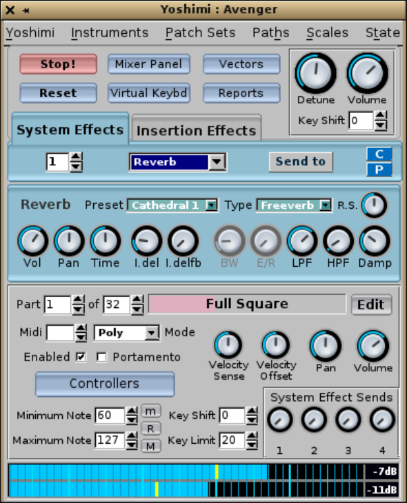
Figure 2: Yoshimi Main Screen
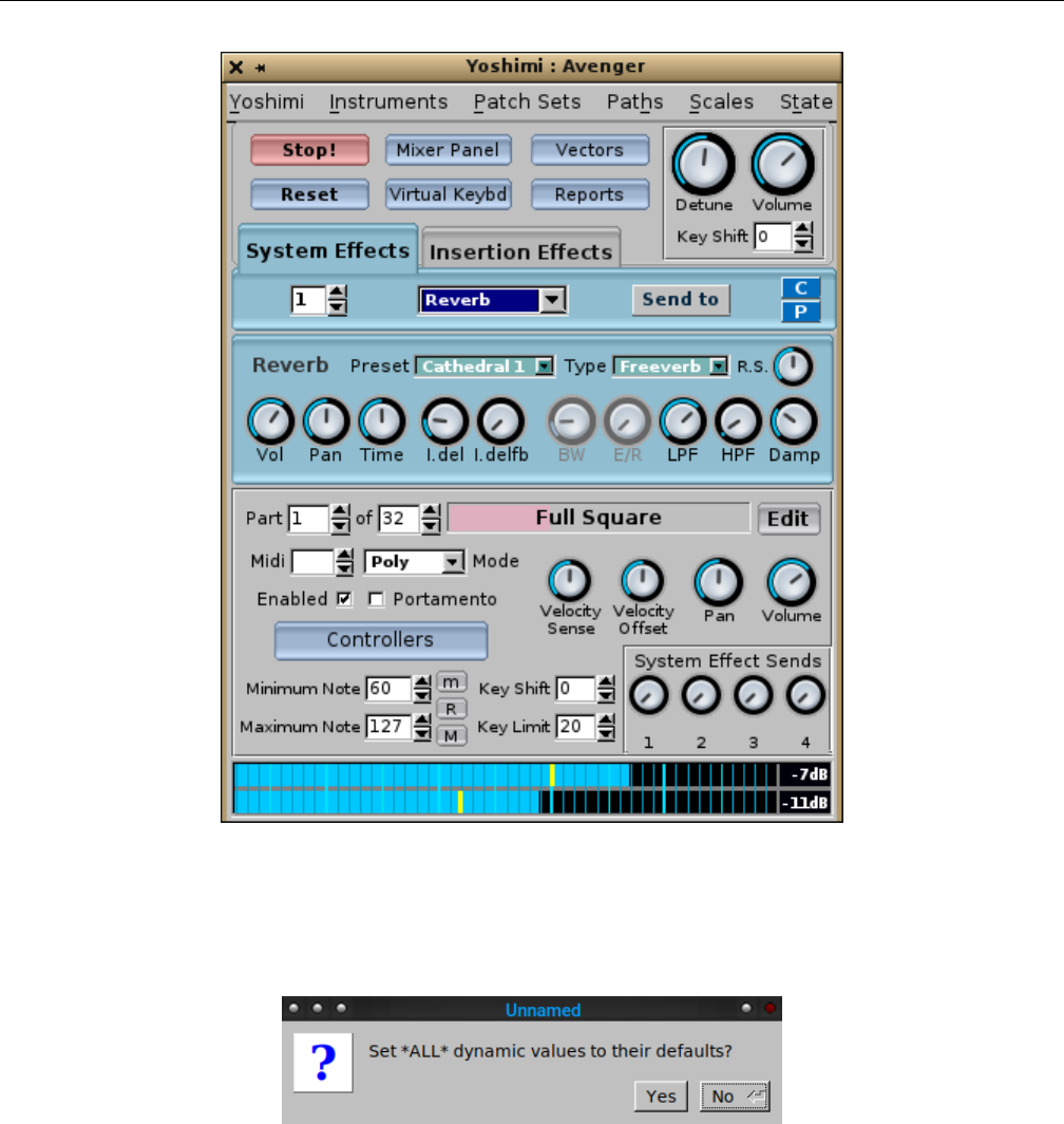
Note that, if one presses the Space bar while the main window has keyboard focus (right after starting
Yoshimi), the following prompt appears:
Figure 3: Space Bar Prompt
Be careful! For this manual, the main window is composed of the following sections:
1. Menu.
2. Top Panel.
3. Effects Panel.
4. Bottom Panel. Includes the VU-meter at the bottom.
One thing to note is that the Detune and Pan buttons no longer have a small red button next to
them to press in order to reset the control to its center value. Starting with version 1.4.0, a right-click on
21
Yoshimi Software Synthesizer
any control in Yoshimi will reset the control’s value to its center position. In version 1.4.1, the Vectors
control appears, with some minor rearrangement of the top panel.
There’s a lot going on with Yoshimi, with no way to describe it in linear order. This manual describes
how to do useful things in each of the sections noted above, while leaving some of the details to be described
in later sections, to which reference can be made for the details. This document depends heavily on index
entries and references. There is also a ”cookbook” at [3]; it is a long way from being comprehensive, but
still has some useful tips.
If one downloads the source code for Yoshimi, in the examples directory one finds a complete song
set, OutThere.mid and OutThere.xmz. Together these produce a fairly complex 12 part tune that makes
Yoshimi work quite hard. Also, after installing Yoshimi, one can find a nice, short introduction to Yoshimi
in Will’s document, /usr/share/doc/yoshimi/The Short Yoshimi Guide.odt, along with a number of
texts files with information that might not yet be present in the long manual.
One last thing to note is that there is a list of important concepts in Section 21 ”Concepts” on
page 247, which one should consult if a term is puzzling.
2 Configuration Files
Let’s cover the configuration files, which have expanded in utility in recent versions of Yoshimi. Under-
standing these configuration file makes it easier to use Yoshimi. Also note that all configuration settings
are exposed to the command line interface as well.
As with most applications, Yoshimi and ZynAddSubFX allow for one to save one’s work and reload
it. In recent versions of Yoshimi, it is possible to autoload a default state on startup, so that Yoshimi
is already configured exactly as desired, with patches loaded and part destinations set. In addition,
Yoshimi now saves settings that have been disabled. In this way, they can be re-enabled without having
to reconstruct them from scratch.
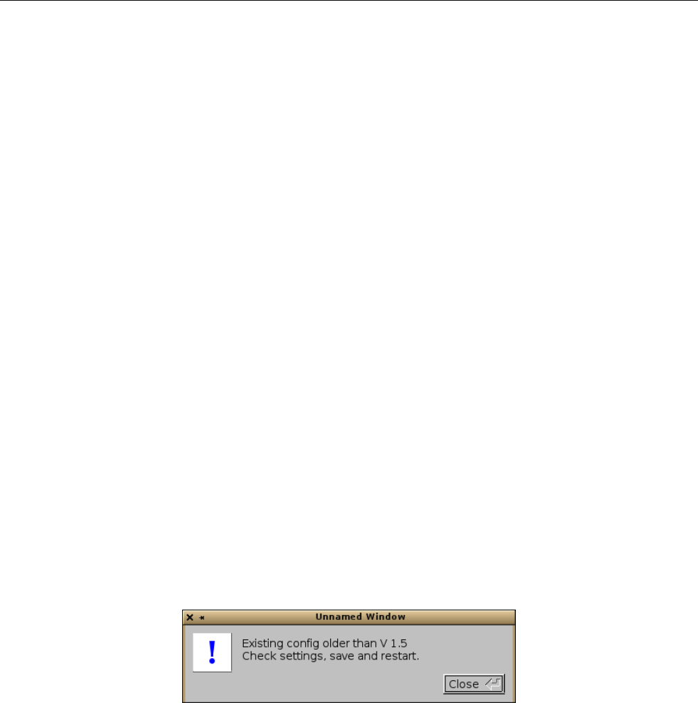
However, the configuration has changed quite a bit, and configurations from Yoshimi 1.4 and earlier
will need to be reconstructed. The following warning will occur if that is the case:
Figure 4: Configuration Warning Dialog
Yoshimi has a number of different files that make up the current configuration. Together, they make
up the concept of a patch set (also called a patchset). Sometimes one will see reference to a ”session”,
but that term is too easy to confuse with the ”session” in ”JACK session manager”.
The last-used file in any configuration section is always at the top of its history list. The main benefit
of this new setup is that now all patch sets, vectors, scales, MIDI Learn, and state - offer the most recent
entry when asked to load or save. On first-time use, when there is no history, one is offered one’s home
directory as a location, regardless of where Yoshimi was called from. Presets are not yet included in this
process.
22

Yoshimi Software Synthesizer
When saving these ”managed” files, one won’t be offered the previous last-used configuration unless
it was seen during that session, either by being loaded, or saved by name. This protects against accidental
overwrites: you’ve been working on ’foo’ for a whole day, saving as you go, then the following day you
start up Yoshimi, and immediately have a completely new idea ’bar’, and start working on it. Without
thinking you save and hit Enter. Oops, you just wiped out ’foo’. Only now you haven’t, because while
loading Yoshimi would see the older file, so the save command just offers the home directory to put a
new name in.
Here is a summary of the files. Please note that the names all start with yoshimi. For example,
.banks is really yoshimi.banks.
•.banks Contains information on the accessible instrument banks, and information to translate
between bank directory names and bank ID values. Current root and current bank settings have
now been moved from banks to the config and instance files, so the banks file now consists only
of the bank structure. On first time start up, Yoshimi will look for ZynAddSubFX banks as well
as Yoshimi banks in the usual locations. It will not look for a ZynAddSubFX configuration file, as
these are no longer relevant.
•.config Contains the setup information configured in the Yoshimi / Settings dialog. This is the
main configuration file. Configuration instances are now in place, so the main configuration file is
common to all, but each instance has its own file for things like current bank, JACK/ALSA settings,
etc. Common settings are only visible in the main instance and completely hidden in all the later
ones.
•.history Recent patch sets are now stored in the .history file. The last-used file in any section
is always at the top of its history list.
•~/.yoshimi history Holds command-line history, which is then available on the next Yoshimi
session.
•.instance(n) Contains the current root/bank, MIDI settings, and preferred engines. Yoshimi now
has instance data separated from the main configuration file, with the name yoshimi-(n).instance.
•.state Contains the information needed to duplicate a complete Yoshimi session that was saved.
•.windows Contains the current layout of windows for reinstantiation at the next startup of Yoshimi.
If there is no such file (~/.config/yoshimi/yoshimi.window) at Yoshimi, then the keyboard is also
opened, alongside the main window, as a help to those new to Yoshimi. And of course that state
will be saved, if present, when Yoshimi exits.
•.xiz An Instrument file. This format is the Legacy or Zyn file format. This format will be
supported forever, although some backward-compatible refinements might be made as time goes on.
•.xiy An Instrument file in the new Yoshimi file format. This format includes all the controllers,
the part mode status (Poly, Mono, Legato) and the Humanise setting. When loading files, Yoshimi
will always look for the .xiy version first, and, if it can’t find it, will then look for the .xiz version.
•.xly A MIDI-Learn file for saving the MIDI-Learn settings in force at the moment this file is saved.
It is also included in the state file (.state).
•.xmz All Yoshimi active data; everything except MIDI-Learn. This file is called a patch set.
•.xpz Presets. A preset is a Yoshimi sub-setting file.
•.xsz Scale Settings.
•.xvy Vector settings. The extension stands for ”Xml Vector Yoshimi”. Vector settings are now
included in both the patch sets (.xmz) and state files (.state. For a good example, see Section 16.4
”Vector / Command Line” on page 201. Vector control settings are now also stored in patch set and
state files.
The entire config set should then be (ignoring the prepended yoshimi):
23

Yoshimi Software Synthesizer 2.1 Configuration Files / Patch Set
•.config
•.instance[n]
•.windows
•.history
•.banks
The .windows file is specific to the GUI, so doesn’t figure in this scheme at all, but it is created or
saved when one exits Yoshimi.
In the file-save dialogs, the file extension is determined by the type of file being saved, and it doesn’t
matter if one enters the extension explicity, or not. If it’s missing, or it is the wrong one, it will be replaced.
This is actually true of almost all file saves, and has been for quite some time now.
For vectors (in common with external instruments and patch sets), the configuration is saved to the
user’s home directory. Once saved, Vectors / Options / Recent is your friend.
Yoshimi can set up critical configuration settings to be writable only by the main instance, but
readable (and used) by any others. In the current version of Yoshimi, this applies to AddSynth Oscillator
Size,Internal Buffer Size, and Alsa Samplerate. These three must be defined before any other
initialisation.
2.1 Configuration Files / Patch Set
A patch set is basically a group of instruments related simply by the user wanting to have them all loaded
at once into Yoshimi. A patch set is stored in a .xmz file. A patch set is akin to a preset, in that it stores
a combination of items, that took awhile to set up, for easy retrieval later.
Patch sets are not the full configuration. They carry most of it, including almost all of the dynamic
settings, but they don’t contain the configuration settings that .state does. The patch set format is
either XML or compressed XML, as explained elsewhere. The Patch Sets / Save External... menu
entry saves files with the .xmz extension.
One of the simplest ways to save one’s work is to save the bulk of the Yoshimi dynamic settings. This
saving can be done through the Patch Sets menu (the File menu in ZynAddSubFX), and will result in
the creation of a .xmz file. Once created, this file will hold the settings for all settings within that setup,
such as microtonal tunings, all patches, system effects, insertion effects, etc. See Section 4.1.3.1 ”Menu /
Yoshimi / Settings / Main Settings” on page 34. Patch sets will save all other instruments regardless of
whether they are activated or not.
In many cases saving everything in a part is not what is desired. Saving a patch later on in an editing
session is one such example. In order to save a patch, one can either save it from the Instruments menu,
or through the Bank window.
2.2 Configuration Files / Config
Often, one will see the extension .config used in the $HOME/.config/yoshimi directory. This file once
contained information to translate between bank directory names and bank ID values. In recent versions
of Yoshimi, this file is much reduced in size, and its ”doctype” is no longer ”ZynAddSubFX”.
The .config file is always going to be specific to one machine and working modes, so no one will
ever want to copy it across even to another Yoshimi environment. Recent patch sets are now no longer
stored in the main .config file, but in a new .history file. The .config file is now a much reduced
24

Yoshimi Software Synthesizer 2.3 Configuration Files / State
common settings – interfaces, sample rate – file. It is a single file that every instance can read, but only
the first one can write.
The .config file has been separated from .instance(n). It is saved only when the user explicitly
calls for it to be saved.
All files are still per instance, as the Yoshimi team haven’t had time to work out exactly how to
manage common files and memory locations for those that should be shared. Yoshimi will still mention
its absense:
$ yoshimi -a -A
Yoshimi is starting
ConfigFile /home/ahlstrom/.config/yoshimi/yoshimi.config not found, will
use default settings ...
The .config file will be readable by all instances of Yoshimi, but writeable only by the main instance.
The relevant controls will be hidden from the other instances. Also, those controls not relevant to LV2
are disabled in that mode. The .config and .banks data now reside in separate configuration files. The
banks file is saved every time there is a normal exit, so the last-used root and bank IDs will always match
what that instance thinks is there. Conversely, the main .config file doesn’t get saved when one starts a
new (unkown) instance of Yoshimi, but the config-changed flag is set, so one has control over whether any
settings are saved. So now, if anything goes wrong with the config files they won’t corrupt one’s carefully
organised bank files, and vice-versa.
2.3 Configuration Files / State
Sometimes one will see the extension .state used in the $HOME/.config/yoshimi directory. These files
contain a lot more information, that needed to duplicate a Yoshimi session that was saved. This file is
a superset of an .xmz file, saving everything. The state file is accessed from the State menu item in
the main window. Its default name is ~/.config/yoshimi/yoshimi.state. This file is auto-loaded when
Yoshimi starts, if it is present. If not present, then the normal settings are in place.
The advantage of this is that once can set up a complete patch set of instruments one commonly
uses, with all their settings, including audio destination. Save it to the default state and it will be loaded,
along with the system settings, every time one starts Yoshimi, if the Yoshimi / Settings / Switches
/ Start With Default State setting is checked. To revert the state, simply uncheck the Yoshimi /
Settings / Switches / Start With Default State setting (and change any other needed), click the
Reset button on the main screen, and save the settings.
The Yoshimi ’state’ file consists of the entire setup, from basic configuration settings to currently-
loaded instrument sets. However, upon investigating some JACK session managers, it looks like they don’t
want (or can’t use) most of the configuration information because they are expecting to be able to change
the state in running instances.
Yoshimi now splits the ’instance’ data from the main configuration. This solves this session issue by
saving only the true configuration locally, and to the state save. However, the ’instance’ data includes
things like ALSA/JACK settings. Currently we can’t change these live (although it would be nice if we
could), but would anyone want to do so from a JACK session manager?
25

Yoshimi Software Synthesizer 2.4 Configuration Files / Instrument
2.4 Configuration Files / Instrument
An Instrument. These files can have two formats, compressed and uncompressed. Uncompressed is set by
Yoshimi / Settings / Main Settings / XML Compression Level set to 0, and compressed is set
by a value greater tha 0.
With the Instrument menu, one can save the file to any given location with the .xiz extension.
Default instruments are never saved, not even in patch sets and states, but if the parts are activated,
that fact is saved; it’s a part feature, not an instrument feature.
2.5 Configuration Files / Scale
Scale Settings. These files store microtonal settings that Yoshimi can use to produce non-standard musical
scales. Recent scales settings are saved and recorded.
2.6 Configuration Files / Presets
Have a favorite setting for an envelope, or a difficult-to-reproduce oscillator? Then presets are for you!
Presets allow for one to save the settings for any of the components which support copy/paste operations.
This is done with preset files (.xpz), which get stored in the folders indicated by Paths / Preset Dirs....
The key thing about using presets is that one must first specify a presets directory! Otherwise, who knows
where they go? A good choice for a preset directory is ~/.config/yoshimi/presets.
In Yoshimi, a preset is any collection of settings that can be saved to the clipboard or to a file, for
later loading elsewhere.
A preset is canned version of a Yoshimi sub-setting. Presets can be copied and pasted using the C
and Puser-interface buttons associated with many of the Yoshimi dialog windows. They make it easy to
save portions of the current settings for later use. For example, resonance settings can be saved.
The naming convention for a preset file is presetname.presettype.xpz, where presename is the
name one types into the Copy to Preset name field, presettype is the name that appears in the Type
field, and xpz is the file-extension for compressed XML preset files.
2.7 Configuration Files / Instance
A new feature of the Yoshimi configuration. It contains the current root/bank, MIDI settings, and pre-
ferred engines. These instance files are totally independent files, distinguished by a number in the file-name.
2.8 Configuration Files / History
A new feature of the Yoshimi configuration. Recent patch sets are now stored in the .history file. For ex-
ample, if the XML Compression option is set to 0, and one exits Yoshimi, then the file ~/.config/yoshimi/yoshimi.history
might contain the following items (ignoring the XML markup):
/home/me/yoshimi-cookbook/sequencer64/b4uacuse/yoshimi-b4uacuse-gm.state
/home/me/sequencer64/contrib/yoshimi/horse.state
26

Yoshimi Software Synthesizer 2.9 Configuration Files / Banks
.history is a single file that every instance can read and write. The .history file is saved only upon
a normal exit, as it is comparatively unimportant.
The history is a single buffer and file, readable and writeable by all instances. This is actually quite
interesting as there can never be a conflict. It is impossible to have two browser lists open at the same
time (try it!) and the lists are always rebuilt from memory every time they are opened. Similarly, the
histories are added too every time a new recognised file is loaded or saved and one can’t physically do
two at the same time – even if one could it would simply mean that one very briefly waited for the other,
which is not an issue as they are not in the realtime thread.
Now, there is also another ”history” file created by Yoshimi:~/.yoshimi history. This file is a
history of commands typed into the command-line interface of Yoshimi; it follows standard readline
practice.
2.9 Configuration Files / Banks
A new feature of the Yoshimi configuration. Currently each Yoshimi instance takes its own copy of the
actual files as it starts up. However, they can all save, delete, or rename the actual files without talking
to the other instances, so one can move a file in one instance, and then try (and fail) to access it from
another.
With the Banks menu, one can assign a patch to a given slot with a bank. This instrument will
remain in that slot for future use until it is deleted. To see the physical location of the .xiz file, one should
check the Yoshimi / Settings / Banks / Root Dirs (File / Settings / Bank Root Dirs) window to
see the paths for banks.
At startup, after all the configuration is complete, the banks are loaded and installed. On a per
instance basis, the first thing this process does is look for a yoshimi(-n).banks file, if it can’t, find that
it then hunts for a yoshimi(-n).config file, and if that fails it does a rescan for banks. In this way it
should be completely backward compatible with any previous config files.
The .banks file is saved every time roots, banks, or instruments are changed, and again on a normal
exit to catch the current root and bank (which don’t otherwise trigger a save). This allows the last-used
root and bank IDs to always match what that instance thinks is there. Note that one needs to have write
permissions to add instruments to the bank. When one saves an instrument to a bank slot, it is given a
filename with the internal name as the leaf-name. When one saves an instrument to an external file, one
is first offered the internal name and the current directory, but one can change it if desired.
By default Yoshimi does not assign a bank ID 0 (zero) in any root. This feature has an interesting
benefit. Several sequencers insist on setting a bank with every program change, and if one doesn’t give a
bank, they will try to set 0. However, Yoshimi is smart enough to ignore any invalid bank ID and remain
with the existing bank number.
As a further protection against rogue sequencers making assupmtions, any attempt to set an invalid
bank or bank root will be ignored. Also, on first-time startup, discovered roots will be given ID numbers
starting from 5, continuing in steps of 5. This makes it easier to re-arrange them to preference. We
recommend that you don’t use 0.
Loading an instrument now updates the Kit window; the kit is all there and looks and sounds
correctly.
On first time start up, Yoshimi will look for ZynAddSubFX banks as well, in the usual locations. It
will not look for a ZynAddSubFX configuration file, as these are no longer relevant to Yoshimi.
Banks are more thoroughly described in Section 21.3 ”Concepts / Banks and Roots” on page 249.
27

Yoshimi Software Synthesizer 2.10 Configuration Files / .bankdir
2.10 Configuration Files / .bankdir
A bit of ancient history has bubbled to the surface. When one creates a new bank in Yoshimi, it inserts
an empty file in the new bank, called .bankdir. For example:
... /banks/Zen Collection/.bankdir
The reason for this is that when scanning for banks (especially at startup) it looks for this file first.
If it can’t find it, then it has to go though the slower process of looking for at least one completely valid
instrument file. Running from SSDs, it probably won’t make a lot of speed difference but it will on a
conventional hard drive, especially if one has lots of banks. So, if one wants to get that little startup edge,
plonk a copy of this file into all your banks. It’s an empty file.
In modern times, one of the main distros creates a warning for the packagers if it sees embedded
dot files, and gets very unhappy if these are empty ones. The obvious answer is to put something there;
Yoshimi now adds a .bankdir file that is useful – when one creates a new bank, this file contains a string
with the Yoshimi version number it was created with, and to add icing to the cake, every time one saves
an instrument file in a bank, this file is created if it wasn’t there, and will have the current Yoshimi version
number.
So now it is be possible to tell how recently a bank was changed, which may have implications if
running modern instruments on older Yoshimi’s or on ZynAddSubFX. Also, the distro will be happier
because the .bankdir file won’t be empty.
For the ”Collection” bank, the version number is 0.0.0; all its instruments were created with Yoshimi,
sometime before version 1.3.0. ”Drums” is set to 1.3.0; ”Companion” is set to 1.5.0.
2.11 Configuration Files / Windows
No, this term isn’t a reference to ”that other operating system”.
A new feature of the Yoshimi configuration. It saves the current layout of windows for reinstantiation
at the next startup of Yoshimi.
2.12 Configuration Files / Format
The Unix file command indicates that the XML files are one of two types:
•exported SGML document, ASCII text. These files are unindented XML data with an encoding of
UTF-8 and a DOCTYPE of ”ZynAddSubFX-data”.
•gzip compressed data, from Unix. These files can be renamed to end in ”.gz”, and then run through
the gunzip program to yield the XML file (but without an .xml extension).
The format depends on the ”XML compression level” option discussed in Section 4.1.3.1 ”Menu /
Yoshimi / Settings / Main Settings” on page 34.
Saving settings or not: If one changes settings, and closes without saving, that means the settings
remain in place only for the current session. If one has changed anything, when one closes Yoshimi, one
will be given a second chance to save them. If one responds ’No’, the next time Yoshimi starts, the old
settings will be restored. An ’undo’ feature would get pretty crazy very quickly.
28

Yoshimi Software Synthesizer 2.13 Configuration Files / MIDI Learn
In the Settings window, Save Settings refers to the entire window, not just individual tabs. The
close buttons are actually outside the frame of the tabs.
Close without saving doesn’t mean revert to previous settings; it means to use the changes, but
don’t immediately store them to the filesystem.
In general, the contents are structured a lot like the user-interface elements that are used to set them.
2.13 Configuration Files / MIDI Learn
The MIDI-Learn data crosses the border between static configuration and dynamic settings. It is stored
in files with an extension of .xly (”XML Learn Yoshimi”). If compression is turned off (Yoshimi /
Settings / Main Settings / XML Compression Level set to 0), this file is an XML/SGML file with
a MIDILEARN section in it.
When saving states, if there are any configured MIDI learned lines, these lines will also be saved.
When one reloads the state they will also be restored. However, if the state file doesn’t have any MIDI
learn data, it will not clear any settings that are already there.
Therefore, be aware that if one now re-saves that state, it will include such MIDI learned data, and
the next time it is loaded, it will overwrite any lines that are already there.
Also note that, during a master reset, the MIDI learn data is the only thing that is not cleared.
These features are designed to give the best protection to a setup that could have taken quite a long
time to set up exactly as desired. In our experiments, we have discovered that we seem to use pretty much
the same controls and actions, and the list of our ’preferred’ settings is slowly increasing.
3 Banks and Roots
In recent versions of Yoshimi, the concepts of banks and roots have undergone a fair amount of change,
including new features to make them easier to manage and easier to automate. There are a lot of details
to understand, too many to include along with the descriptions of the user-interface elements that control
them. Therefore, this new section is devoted to banks and roots. It is an elaboration of material originally
presented in Section 21.3 ”Concepts / Banks and Roots” on page 249.
At one time, one could in theory have 1000 roots, 1000 banks and 1000 presets. However, now roots
and banks were trimmed to what can be addressed from MIDI. One can supposedly still have 1000 presets,
though. Anyway, 128x128x160 = 2621440 instruments should be enough for anyone.
All root, bank, and instrument IDs are used by MIDI controls, and as of version 1.3.6 will also be
accessible to the command line.
The file Banks.txt in the Yoshimi source-code bundle makes an important point about a transition
(in newer versions) to tagging roots (directories) and banks with an ID code:
One no longer has the concept of a default root directory, but a current one. This can by changed at any time
without requiring a restart, so there is no longer a need to display the (confusing) contents of all roots. Also,
roots now have ID numbers associated with them, but no changes have been made to the actual directores to
achieve this. Instead the IDs are stored in the config file. The same ID system is used for banks, again without
making any file system changes.
At first run (and whenever new root directories are set) unknown roots and banks are given these IDs.
Once set they will not change no matter how many more roots and banks are later added. One can however,
manually change root directory IDs in the ’Bank Root Paths window’ accessible from the ’Paths’ item in the
29

Yoshimi Software Synthesizer 3.1 Roots
main window. Also, there is a new Banks window so that these can be set up, moved and renamed in exactly
the same way as instruments can. With these IDs, roots and banks can be grouped/ordered by function instead
of alphabetically. When using the GUI, one will always know exactly which root and bank one fetches an
instrument from.
One can quickly step between roots, banks and instruments with the so marked buttons in each of these,
and if one right-clicks on them one will close one window as one opens the other.
The significance of all this is that one’s MIDI sequencer can now reliably use these ID numbers to select
roots, banks and (already available) instruments. That Rosegarden or Muse file one saves today will be just as
valid in the future, unless one makes the deliberate choice to change some IDs. Indeed, one can now start with
an ’empty’ Yoshimi, and via MIDI, set roots, banks and load instruments into parts (enabling the parts as one
does so) swapping banks and roots as necessary. While the MIDI file runs it can silently pull instruments from
any root/bank into any non-sounding part without disturbing the playing ones.
In Yoshimi / Settings / MIDI one can enable or disable all these features, and can define which CCs one
wants to use. Bank can be either MSB or LSB (as before). Root can be any non-reserved CC but including
the one not in use for Bank. Also, Extended Program Change now has the same restrictions as Root, and
these three are all cross-checked against each other. As an example, one might set Bank to LSB amd Root to
0 (MSB), effectively giving one extended bank control compatible with all sequencers.
Also, different instances have their own config files so that one can have (say) the main instance with current
root(9), bank(23) while instance 4 has current root(2), bank(6). One can call up instances by number and thus
access saved settings for that instance. As each instance has its own MIDI and audio ports, they can behave
more-or-less independently.
In doing all of this we have completely changed the way we manage the structure internally, resulting in much
greater efficiency, at the cost of only a slightly slower startup. Swapping roots performs *no* file operations.
Swapping banks only fetches the directory list of the newly selected bank. Changing an instrument doesn’t
have to search for a file, only load from its already known location.
If one changes a bank root path, either through the gui or via MIDI, it will always reset the current bank
to the lowest numbered one it can find. This is because there may not be a bank in the new root with the same
ID, and even if there is, there is no guarantee that it will have the same name or contents.
Also if an attempt is made to reload the same root, nothing will actually happen. The same is true of banks.
Both of these are kept fully up-to-date so there would be no point.
However, reloading the same *instrument* will be performed every time, as one may have changed what is
currently loaded without saving it. This provides an effective ’restore’ operation.
Finally, it is generally advisable to make root and bank changes on channel 1 so that one can more easily
keep track of them. However they are not channel sensitive as they don’t directly affect the sound, so one can
set them in any convenient channel then perform individual program changes on the desired channels.
It has always been possible to swap and move instruments within a bank, and since V 1.3.5 it was
possible to swap banks within a bank root, but now one can swap/move instruments across any banks and
any bank roots. One can also move whole banks across bank roots. These extensions use exactly the same
controls as before. However, it isn’t just a case of changing IDs. Files are actually moved, so additional
protections and warnings are put in place.
There are also bank importing and exporting controls and since version 1.5.8 these have been made
available to the CLI with specific IMport and EXPort controls.
A ”CC” is a MIDI ”continuous controller”. A MIDI bank change is usually a CC#0 value of 0,
followed by a CC#32 value of X, where X is the desired bank number from 0 to whatever. (However, in
some cases it may simply be a CC#0 on its own with a value of X). Many synths also require that one
send a program change after the bank change, to select the program within the bank.
3.1 Roots
In Yoshimi, a root is a location in which banks can be stored. It is basically a directory, though it
ultimately is assigned a number by Yoshimi, presumably to be able to access it in an automated way. By
choosing a root and making it the current root, one can hone in on a smaller collection of banks.
30

Yoshimi Software Synthesizer 3.2 Banks
One cannot reach root paths through the Yoshimi / Settings menu any more; it was causing
a nightmare of syncing with the other entry routes. One can reach it from the Banks window or the
Instruments window, and both of the latter also have multiple entry routes. Roots can also be reached
through the Yoshimi / Paths menu.
3.2 Banks
Another important concept in Yoshimi is banks. Instruments can be stored in banks. These are loaded
and saved automatically by the program. On program start, the last used bank is loaded. A single bank
can store up to 128 instruments normally, and 160 using extended programs.
Also note that, as well as bank and program changes, there is the ability to set a MIDI CC to access
the voices from 129 to 160 (numbered re 1). All the Bank controls are contained in a tab in the main
Settings window, and take immediate effect.
Bank root directories are identified with ID numbers that can be changed by the user in the user-
interface. This feature is also made available for selection over MIDI. MIDI only sees banks in the current
root directory, but all banks are accessible to the user-interface.
3.2.1 Bank Directories
Banks are arranged in directories, with each directory containing a number of instrument files.
Each instrument’s file-name should begin with a 4-digit number (left-padded with 0’s to make it 4
digits long). This number can serve as a MIDI patch number for automated selection of the instrument
via a MIDI program-change message.
Unnumbered instruments in a bank will be given a temporary ID starting from number 160 and
working down. If those numbers already exist then they will be skipped over. This can get very confusing.
However, if one simply loads it and re-saves it to the same instrument slot, it will gain that ID and be
properly fixed. One can then move-swap it with others.
4 Menu
We’re now ready to describe the user-interface of Yoshimi! The Yoshimi menu, as seen at the top of
Figure 2”Yoshimi Main Screen” on page 21, is fairly simple, but it is important to understand the
structure of the menu entries.
4.1 Menu / Yoshimi
The Yoshimi menu entry contains the sub-items shown in Figure ?? ”??” on page ??. The next few
sub-sections discuss the sub-items in the Yoshimi sub-menu. (Note that, in ZynAddSubFX, this menu is
called the File menu.)
31
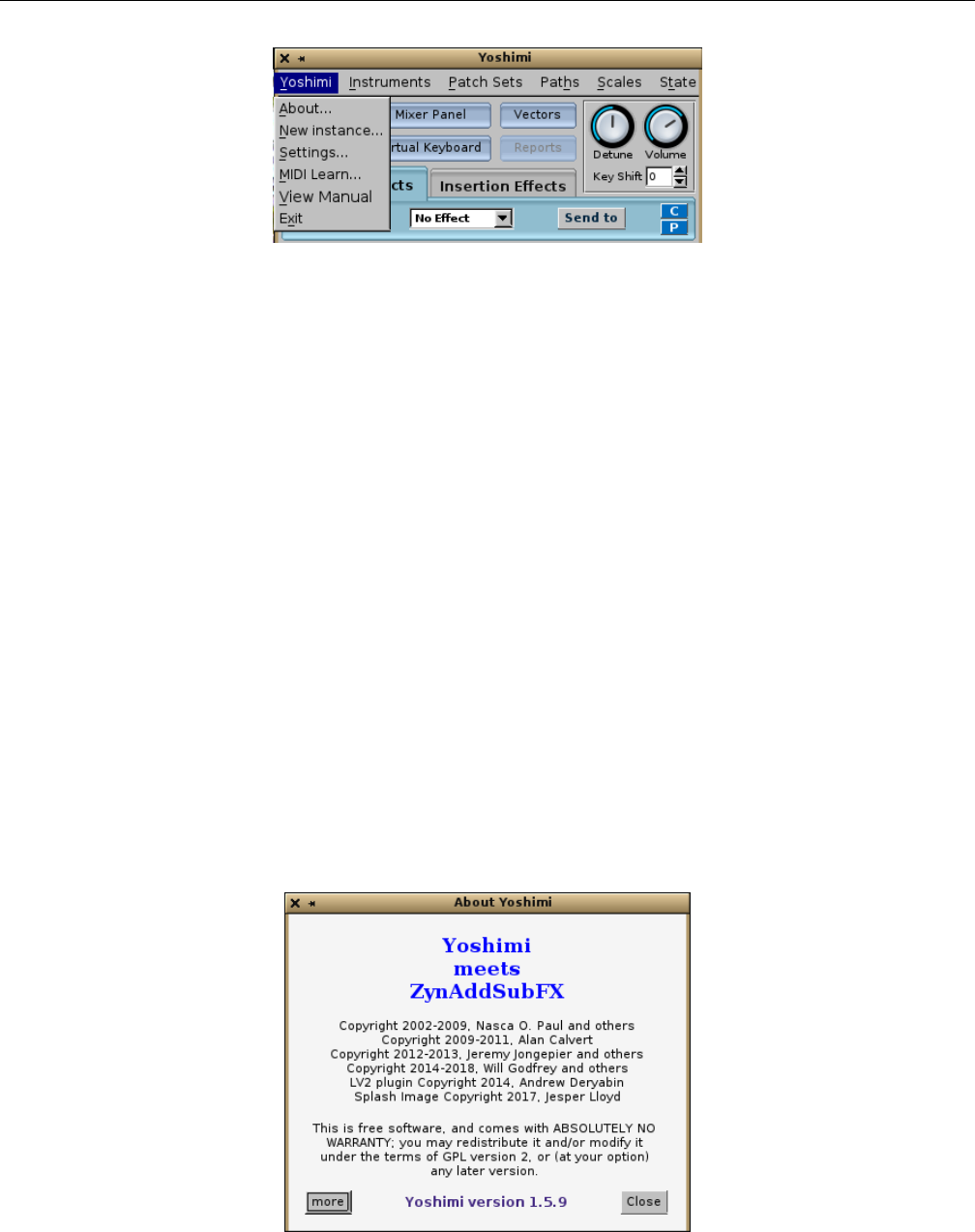
Yoshimi Software Synthesizer 4.1 Menu / Yoshimi
Figure 5: Yoshimi Menu
The items it contains are:
1. About...
2. New instance
3. Settings...
4. MIDI Learn...
5. View Manual...
6. Exit
The Vectors menu entry of version 1.4.0 has been moved to its own button in version 1.4.1, as can be
seen in the figure. See Section 16.2 ”Vector Dialogs” on page 195, which presents this dialog and describes
it.
MIDI Learn is a new feature of Yoshimi, and is described below.
View Manual is a new feature of Yoshimi. It currently requires that a PDF viewer be installed. Note
that some viewers might not work properly (e.g. apvlv ([1]).
4.1.1 Menu / Yoshimi / About...
There is no Help menu in Yoshimi. Therefore, the About dialog appears in the Yoshimi menu, as shown
in Figure 6”Yoshimi Menu, About Dialog” on page 32. These guys need some acknowledgment for their
hard work! And they acknowledge the massive groundwork laid by the ZynAddSubFX project.
Figure 6: Yoshimi Menu, About Dialog
32
Yoshimi Software Synthesizer 4.1 Menu / Yoshimi
This has a new ’more’ button that changes the window to an alphabetic list of all those who have
helped Yoshimi. Somtimes just a hint from these friends has been enough to pave the way for extensive
improvements.
Figure 7: Yoshimi Menu, Contributors
4.1.2 Menu / Yoshimi / New instance
The New instance menu entry creates a new instance of Yoshimi. If JACK is running, start a normal
(JACK-using) instance of Yoshimi. Then use this menu entry. Yoshimi will start another instance of itself,
with a prompt to accept the next available instance ID or to change it. The presence of this instance can
be verified by running a JACK session manager such as QJackCtl. In a non-JACK setup it won’t fail, but
in the absence of any specific setting, it will have null audio, but (probably) will still connect to ALSA
MIDI. Not too useful, but we should test that sometime.
It is important to note that each instance of Yoshimi has its own configuration file. Each also has its
own MIDI and audio ports. Thus, these instances are partly independent of each other. The new instance
tries to open a Yoshimi instance based on the configuration found in the file ~/.config/yoshimi/-
yoshimi.configXX, where XX is the ID one supplied.
Opening a new instance creates a copy that has it’s own dynamic memory for running storage. Some
data (such as recent history) is shared between instances. This is done only where instances actually need
to be in sync. The bank structure should be synchronised, but currently isn’t.
Instances no longer fight for access to JACK/ALSA audio; they simply try to find another route to
a soundcard. Failing to find one, they revert to null audio, but nonetheless start cleanly.
The list of hidden ”base parameters” that are set only by the main instance is now:
•ALSA Sample Rate
•Internal Buffer Size
•AddSynth Oscillator Size
•XML Compression Level
•Show Splash Screen
•Enable GUI
•Enable CLI
33

Yoshimi Software Synthesizer 4.1 Menu / Yoshimi
In the other instances these are now hidden instead of deactivated. This behavior makes sense, as
they are never enabled in the other instances of Yoshimi. This is more consistent, making Yoshimi’s
configuration directory more tidy.
4.1.3 Menu / Yoshimi / Settings...
The Yoshimi Settings dialog contains five tabs that control the major and overall settings of Yoshimi. At
the bottom of this dialog are two buttons: Save and Close and Close Unsaved.
Please note that the Save and Close and Close Unsaved buttons apply to the whole Settings
window. Furthermore, the ”saving” does not refer to preserving the changes that have been made in any
of the tabs for the current Yoshimi session. Any changes made in Settings always remain in place for
the current Yoshimi session. However, the changes to the settings are saved to the state file only if Save
and Close is clicked.
1. Save and Close. This selection saves the settings made in all of the tabs to the state file, and
closes the Yoshimi settings dialog.
2. Close Unsaved. Close Unsaved, Main Settings.
This selection closes the Yoshimi settings dialog. However, note that any changes made in the tabs
are preserved. They are preserved for the current Yoshimi session, but are not saved to the filesystem.
Here are the tabs included in the main settings of Yoshimi as of version 1.4.1; each is described in
its own section.
•Main settings
•Switches
•Jack
•Alsa
•MIDI
4.1.3.1 Menu / Yoshimi / Settings / Main Settings
The Main Settings tab controls the main configuration items that follow, which apply to all patches/instruments.
The main settings are shown in Figure 8”Yoshimi Main Settings Tab” on page 35. Some settings only
take effect after restarting the synthesizer. In Main settings, only the items marked with an asterisk
(’*’) need a restart. The settings dialogs have changed gradually as Yoshimi has progressed.
34
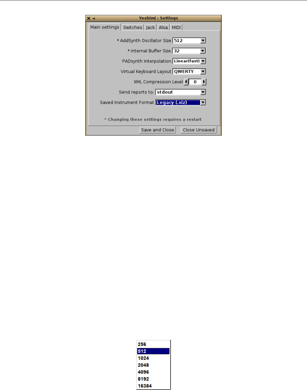
Yoshimi Software Synthesizer 4.1 Menu / Yoshimi
Figure 8: Yoshimi Main Settings Tab
The following settings exist in the Main settings tab:
1. AddSynth Oscillator Size
2. Internal Buffer Size
3. PADsynth interpolation
4. Virtual Keyboard Layout
5. XML compression level
6. Send reports to
7. Saved instrument Format
1. AddSynth Oscillator Size. ADDsynth Oscillator Size (in samples). This item used to be called
”OscilSize”. Sets the number of the points of the ADDsynth oscillator. Bigger is better, as it results in
a more mathematically-correct waveform, but it takes more CPU, though it has no effect on latency. In
an all-JACK environment, JACK determines the latency. There are very few occasions where one might
want the internal buffer smaller than the JACK size, and none where it should be bigger. If it is bigger,
the extra space will (to a small degree) represent wasted processor use.
See Section ?? ”??” on page ??, which goes into performance-related details.
The default value for Yoshimi is shown marked with an asterisk, and the default value for Zy-
nAddSubFX is 512. This asterisk/plus-sign convention is used throughout this manual. See Figure 9
”OscilSize Values” on page 35, shown below for the AddSynth Oscillator Size drop-down element.
Values: 256, 512*, 1024, 2048, 4096, 8192, 16384
Figure 9: AddSynth Oscillator Size (samples)
35
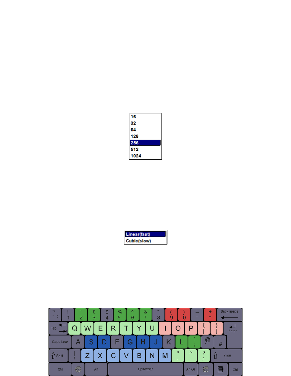
Yoshimi Software Synthesizer 4.1 Menu / Yoshimi
2. Internal Buffer Size. This is a new item for version 1.3.6. It is actually the old Period Size
field from the Alsa tab. It sets the granularity of the sound generation. To find out the internal delay
in milliseconds, divide the buffer-size value by the sample-rate, then multiply the result by 1000: For
example, 256/44100 ∗1000 = 5.8ms.
The default internal buffer size has been reduced from 1024 to 256. One gets better latency that way.
Almost all modern computers can run Yoshimi with the current default (smaller) buffer-size value, and
many will do so at 64 frames (and even 16 frames!) without any special precautions.
Note that, for ALSA, if the audio destination is ”default”, then ALSA decides on the buffer size
(among other settings), and Yoshimi will set it’s internal buffer size to match, which always seems to be
1024.
Values: 64, 128, 256*, 512, 1024, 2048, 4096, 8192
Figure 10: AddSynth Internal Buffer Size (old)
Note that there are two more values, not shown in this old diagram.
3. PADsynth interpolation. See Figure 11 ”PADSynth Interpolation” on page 36, shown below,
for the interpolation values. From an email conversation with Paul Nasca, Will notes that the sound
improvement with cubic interpolation is quite subtle, and requires a well designed audio setup, a PADsynth
instrument with a fair amount of high-frequency content... and good hearing!
Figure 11: PADSynth Interpolation Values
Values: Linear(fast)*, Cubic(slow)
4. Virtual Keyboard Layout. The virtual keyboard is useful, but it is difficult to move the mouse
rapidly to the next key on the virtual keyboard. Therefore, Yoshimi supports using the computer keyboard
to produce notes.
Figure 12: QWERTY Virtual Keyboard Layout
36
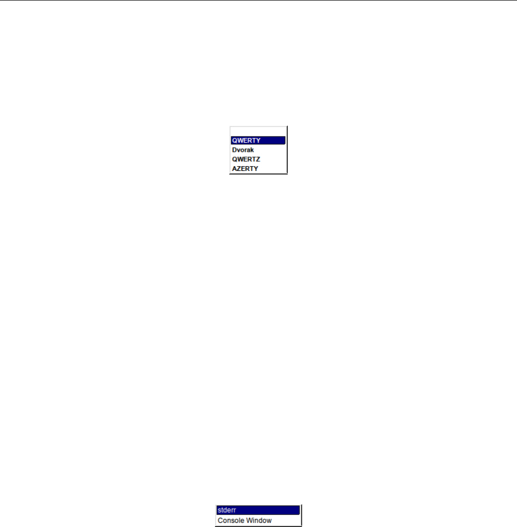
Yoshimi Software Synthesizer 4.1 Menu / Yoshimi
See Figure 12 ”QWERTY Virtual Keyboard Layout”, for the mapping of the computer keyboard
to the virtual keyboard. Three octaves (blue, green, and red) are available, with the dark keys of each
color representing the ”black” keys. Note that this is a QWERTY layout. Yoshimi also supports other
keyboard layouts. See Figure 13 ”Virtual Keyboard Layout” on page 37, for the virtual keyboard layout
settings drop-down.
Values: QWERTY*, Dvorak, QWERTZ, AZERTY
Figure 13: Virtual Keyboard Layout Values
5. XML compression level. Gzip Compression level of Yoshimi XML files. The settings and instru-
ments of Yoshimi are preserved in XML files. The value of 0 indicates that the XML file is uncompressed.
In general, 0 is a setting for debugging only. Setting this option makes the XML files a bit larger,
perhaps larger by a factor of more than 10, making a 10K file into a 180K file. For a little ”wasted” space
and time, one can view the XML file in a text editor. If one’s system is tight on disk space, higher levels
of compression can be specified. Using XML compression can also save file access time which may be
beneficial if one’s computer is borderline on latency. This setting should stay at 3 if one is going make
instruments publicly available, as some older versions of Yoshimi and ZynAddSubFX don’t recognise
uncompressed files. This also applies if one is going to save large patchsets that will be loaded while
running. Uncompressing is much faster than file loading.
Values: 0 to 9, 3*
6. Send reports to. Notices and error messages can be sent to the standard error log of the terminal
in which Yoshimi can be run, or, more usefully, to an output console window. In some versions of Yoshimi
these messages were pushed in reverse order, to avoid manually scrolling and to make the most recent
statuses easily visible. However, a method has now been found to auto-scroll and keep the most recent
entry visible, so new entries are in normal reading order.
See Figure 14 ”Send Reports” on page 37. It provides a depiction of the selection drop-down.
Values: stderr*, Console Window
Figure 14: Send Reports To
If the Console Window option is chosen, then the Reports button in the effects panel is enabled.
Pressing the Reports button brings up a small console dialog, as shown in Figure 15 ”Yoshimi Console
Window” on page 38.
37
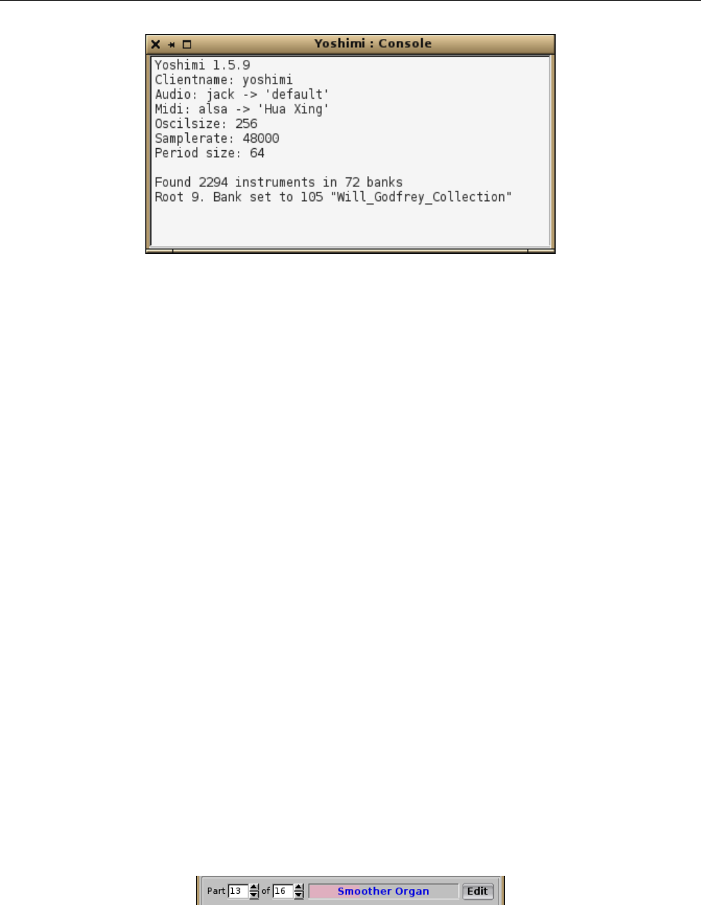
Yoshimi Software Synthesizer 4.1 Menu / Yoshimi
Figure 15: Console Window
Note that numbers that are shown (such as part numbers) all start from 1, not 0.
Loaded 65 "Hyper Arpeggio" to Part 1
Loaded 10 "Arpeggio11" to Part 2
Loaded 41 "Soft Arpeggio4" to Part 3
Loaded 67 "Glass Arpeggio1" to Part 4
An interesting feature of the console window is that one can identify user-interface elements of the
Yoshimi configuration in this window by a middle-click on the user-interface element. (Unfortunately,
those new single-button touchpads make it impossible to provide a middle-click, so one would need a
mouse!)
Information about each knob middle-clicked is pushed to the top of the windows in reverse order.
Information about an earlier left-click is shown at the bottom of the figure. Each left-click (”Button 1”)
will increase the parameter represented by the knob, and each right-click (”Button3”) will decrease the
parameter represented by the knob, and each change is reported in the console window. And, of course,
each middle-click changes nothing, but reports the current value in the console window. This feature lets
one gather the information needed to control the parameter from the command-line. The output can be
selected, copied, and pasted to a script or archive text file for safe-keeping.
7. Saved instrument Format. This new (1.5.5) feature provides a choice between the old instrument
format and a new format. The Legacy format has a file extension .xiz. The Yoshimi format has a file
extension .xiy.
Values: Legacy (.xiz), Yoshimi (.xiy), Both (.xiz + .xiy)
Some users wanted a way to store the Controllers settings with an instrument, as they can make
a dramatic difference to the sound. There is now a superset of instruments that can be saved instead
of, or as well as, the standard ones. On loading, Yoshimi will look for the extended version (.xiy) first.
This applies to instruments in banks, as well as externally saved instrument. If one has an extended
type loaded, the instrument name will be in a blue font, instead of black. This also applies to the stored
instruments in bank slots.
Figure 16: Extended File Format Font
38
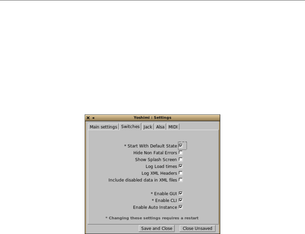
Yoshimi Software Synthesizer 4.1 Menu / Yoshimi
This is part of the rationale of the new instrument format: We will never make any changes to the
standard instruments, and one will always be able to load and save them. However, we will incrementally
add improvements and refinements to the new format, with compatible adjustments for the standard-
format instruments, where appropriate.
There is a caveat when handling instruments in banks. If one sets for only Legacy or only Yoshimi,
but have previously set for both, saving to such a dual entry will erase the one that wasn’t selected.
Currently, it is not known why that happens (banks are ’interesting’).
4.1.3.2 Menu / Yoshimi / Settings / Switches
Many of the check-box items have been moved into this new tab, to reduce clutter.
Figure 17: Yoshimi Switches Tab
The following settings exist in the Switches tab:
1. Start With Default State
2. Hide Non Fatal Errors
3. Show Splash Screen
4. Log Load times
5. Log XML headers
6. Include disabled data in XML files
7. Enable GUI
8. Enable CLI
9. Enable Auto Instance
1. Start With Default State. Requires Yoshimi to be restarted, to take effect. This setting allows
Yoshimi to be initialized with one’s own initial state file that matches one’s usual work setup. The default
state file is named ~/.config/yoshimi/yoshimi.state.
If the Reset button on the main screen is click, then this file is loaded, instead of reverting to the
first-run default state of Yoshimi.
2. Hide Non Fatal Errors. Especially when running from the command line (with reports going
there too), under some circumstances one can get a swamp of low-level error messages (such as XRUNs)
39

Yoshimi Software Synthesizer 4.1 Menu / Yoshimi
that is so large that one cannot work out what is going on. This feature disables these error messages;
it is a work in progress to catch the bulk of them, while still reporting top-level messages and ones that
cause a forced exit (surely not!)
3. Show Splash Screen. This item will speed up the start-up of Yoshimi slightly if unchecked, by
not showing the splash screen while files are being loaded.
4. Log Load times. Provides a way of noting problematic patch sets, which may take a long enough
time to load so as to affect the smoothness of playback.
5. Log XML headers. This item sends the information to the console window (or stderr) so that
one can then see what ynAddSubFX/Yoshimi version created the file.
6. Include disabled data in XML files. Allows disabled data to be stored in the XML file. This
makes it a lot easier to re-enable a setting later.
7. Enable GUI. If checked, the user-interface is enabled. This setting is normally what you want. If
one unchecks it, it warns that disabling the GUI can only be reversed from the command line.
8. Enable CLI. If checked, the command-line interface is enabled. Note as of V 1.5.6 it has been
possible to disable both the user-interface and the command line at the same time. This means that
Yoshimi can only be closed by sending a special MIDI message (CC 99, 68, CC 98, 68). Alternatively one
could send a system shutdown message.
9. Enable Auto Instance. If checked, then, if any other instances were open at the time you close
the main instance, then these other instances will be re-opened next time one runs Yoshimi.
If these instances each have their own Start with Default State switch checked, and if there is a
valid default state for them, then these instances will also have their default state loaded. Therefore, just
by starting the main instance, one can have a highly-detailed multi-instance setup installed. This setup
will include such things as JACK/ALSA audio and MIDI, and a complete patch set, etc.
4.1.3.3 Menu / Yoshimi / Settings / Jack
JACK is the ”Jack Audio Connection Kit”, very useful for increasing audio performance and configura-
bility. When using the JACK audio backend, instruments can be individually routed and sent to the main
L/R outputs. This is controlled from the panel window, Section 7.1 ”Mixer Panel Window” on page 101,
and the settings are saved with all the other parameters.
Direct part outputs carry the Part and Insertion effects, but not the System ones.
40
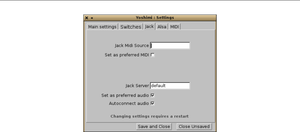
Yoshimi Software Synthesizer 4.1 Menu / Yoshimi
Figure 18: JACK Settings Tab
The following items are provided by the Jack settings:
1. Jack Midi Source
2. Set as preferred MIDI
3. Jack Server
4. Set as preferred audio
5. Autoconnect audio (new, 1.3.9)
1. Jack Midi Source. Jack MIDI Source. It is possible to have more than one JACK MIDI source.
This option tells this instance of Yoshimi which JACK client to try to auto-connect to for MIDI input.
This option corresponds to the Yoshimi command line option --jack-midi(=device).
Values: default*, name name; see ”man jackd” for details.
2. Set as preferred MIDI. Set as preferred MIDI for JACK. This setting determines which MIDI
connections a particular instance will first attempt. The switches are mutually exclusive across JACK and
ALSA, so if one checks ALSA for MIDI, it automatically unchecks JACK for MIDI. As well as from the
GUI, this setting can be set (for instance 0) from the command line, both at start-up and once running.
3. Jack Server. Jack Server Name. It is possible to have more than one JACK server running. This
option tells this instance of Yoshimi which JACK server to use. This option corresponds to the Yoshimi
command line option --jack-audio(=server).
Values: default*, name name, as set by jackd --name; see ”man jackd” for details.
4. Set as preferred audio. Set as preferred audio for JACK. This setting determines which audio
connections a particular instance will first attempt. The switches are mutually exclusive across JACK and
ALSA, so if one checks ALSA for audio, it automatically unchecks JACK for audio. As well as from the
GUI, this setting can be set (for instance 0) from the command line, both at start-up and once running.
Note that any of these setting changes require a restart of Yoshimi to take effect.
5. Autoconnect audio. Sets Yoshimi to connect automatically to the JACK server, just like the -K
command-line option does. (However, note that the command-line has no way to disable this feature it
the configuration has been saved.)
41

Yoshimi Software Synthesizer 4.1 Menu / Yoshimi
4.1.3.4 Menu / Yoshimi / Settings / Alsa
A significant improvement is to the handling of ALSA audio, which is still very important for some
people. Until now, Yoshimi has insisted on a 2-channel, 16-bit format. Tests have shown that virtually all
motherboard sound chipsets will handle this, but many external ones don’t.
From Yoshimi 1.3.6 onwards, when using ALSA audio, Yoshimi first tries to connect 2 channels at
32 bit depth. If that connection does not succeed, then Yoshimi negotiates whatever the soundcard will
support. For example, a card might support only 24 bits, and 6 channels. So Yoshimi will fall back to
24 bit, and, due to its own limits, will use only channels 1 and 2. With external sound modules in mind,
endian swaps are also implemented.
To be able to reliably use ALSA audio, one needs to set a card name, not just ”Default”. In a terminal
window enter the following command:
$ cat /proc/asound/card*/id
The result of this command should be something like:
PCH
K6
Go to the ALSA settings tab illustrated below, and in Alsa Audio Device enter, for example,
”hw:PCH”. This ensures one will always connect to this card at startup regardless of the order this and
other ones. Another benefit of using this hardware name is that ALSA will now use Yoshimi’s internal
buffer size (256), otherwise ALSA will force Yoshimi to accept its default size (usually 1024).
One can also set the sample rate, but bear in mind that not all cards can use all of these. The sample
rates 44100 and 48000 are almost always available. If one sets a Midi Device as well (such as a keyboard)
Yoshimi will try to find and connect to this device at startup.
To find the MIDI devices available, try:
$ grep Client /proc/asound/seq/clients
The result of this command should be something like:
Client info
Client 0 : "System" [Kernel]
Client 14 : "Midi Through" [Kernel]
Client 128 : "TiMidity" [User]
It is not obvious how ALSA audio is controlled and who takes command. If one sets a specific audio
destination, then Yoshimi makes a request. It’s often a negotiation on bit depth and channel count, but
Yoshimi nearly always gets to decide the buffer size, which is the internal buffer size. However, if the
destination is ’default’ then ALSA decides on the sound card, bit depth, number of channels and the
buffer size, and Yoshimi will set it’s internal buffer size to match. On most machines this seems to be
1024.
42
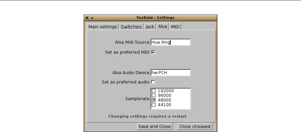
Yoshimi Software Synthesizer 4.1 Menu / Yoshimi
Figure 19: ALSA Settings Tab
1. Alsa Midi Source. ALSA MIDI Source. The purpose of this setting is the same as the command
line option --alsa-midi="name". It is used so that Yoshimi can auto connect to a MIDI source such as a
keyboard. For example, the one that Will has identifies itself as name = ”Hua Xing”. A port name, such
as ”128:0” (for one of the ports provided by TiMidity) should work as well. If the destination is ”default”,
then ALSA decides on the sound card, bit depth, number of channels and the buffer size, and Yoshimi
will set it’s internal buffer size to match. On most machines this always seems to be 1024.
Values: default*
2. Set as preferred MIDI. Set as preferred MIDI for ALSA. This setting determines which MIDI
connections a particular instance will first attempt. The switches are mutually exclusive across JACK and
ALSA, so if one checks ALSA for MIDI, it automatically unchecks JACK for MIDI. As well as from the
GUI, this setting can be set (for instance 0) from the command line, both at start-up and once running.
3. Alsa Audio Device. ALSA Audio Device. This specifies the sound card to which Yoshimi can
connect. Normally, this will be an ALSA hardware specification such as ”hw:0”. ALSA audio also lets
one connect to a sound card by name. For example, with a Komplete Audio KA 6 sound card, the device
specification is ”hw:K6”. This feature is particularly useful for USB modules, as one can never be sure
where they appear numerically.
Values: default*
4. Set as preferred audio. Set as preferred audio for ALSA. This setting determines which audio
connections a particular instance will first attempt. The switches are mutually exclusive across JACK and
ALSA, so if one checks ALSA for audio, it automatically unchecks JACK for audio. As well as from the
GUI, this setting can be set (for instance 0) from the command line, both at start-up and once running.
5. Samplerate. Sample Rate. Sets the quality of the sound, higher is better, but it uses more CPU. One
can select from a list. Note that both ALSA and JACK will support the 192000 rate, if the sound-card
supports it. To find out the internal delay in milliseconds, divide the buffer-size value by the Sample Rate
and multiply the result by 1000 (256 / 44100 * 1000 = 5.8 ms).
Note that, as of version 1.3.6, the Period Size field has been removed from the Alsa tab, and is
replaced by the Internal Buffer Size field in the Main Settings tab. Note that any of these setting
changes require a restart of Yoshimi to take effect.
43
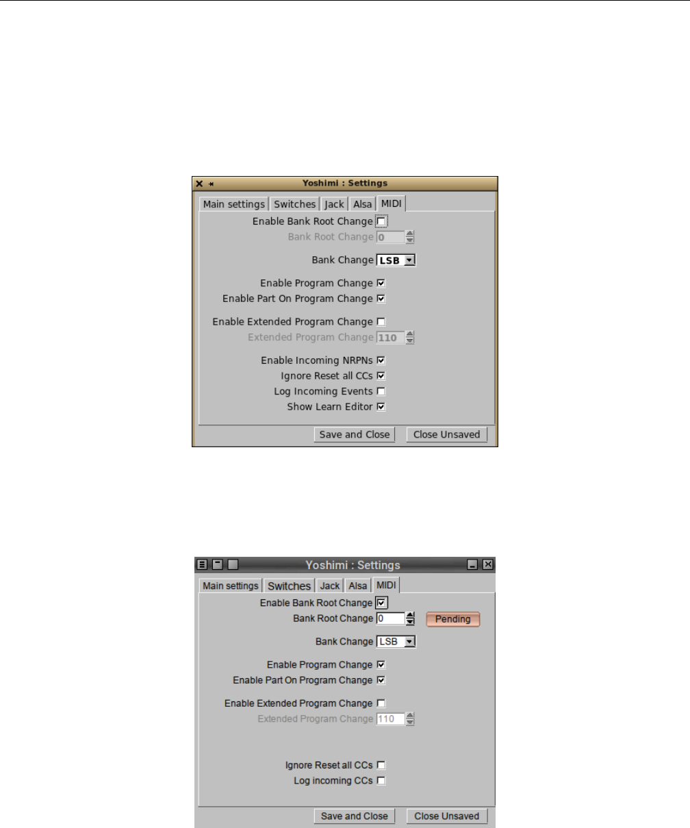
Yoshimi Software Synthesizer 4.1 Menu / Yoshimi
Values: 192000, 96000, 48000*, 44100
4.1.3.5 Menu / Yoshimi / Settings / MIDI
The CC settings tab has been renamed the ”MIDI” tab. This tab, shown in Figure 20 ”MIDI Preferences”
on page 44, presents MIDI bank-root, bank, program change, and extended program change settings, plus
some new values.
Figure 20: MIDI Preferences Tab
A recent feature is that some changes to the items in this tab cause a red Pending button to appear.
Pressing this button saves that particular change.
Figure 21: MIDI Settings Pending
The following items are provided by the MIDI settings tab:
1. Enable Bank Root Change
44
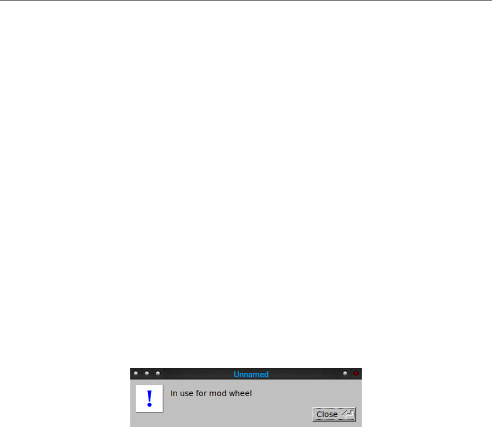
Yoshimi Software Synthesizer 4.1 Menu / Yoshimi
2. Bank Root Change
3. Bank Change
4. Enable Program Change
5. Enable Part On Program Change
6. Enable Extended Program Change
7. Extended Program Change
8. Enable Incoming NRPNs
9. Ignore Reset all CCs
10. Log Incoming CCs
11. Show Learn Editor
The concepts of banks and roots is very useful. See Section 21.3 ”Concepts / Banks and Roots” on
page 249. The settings in this tab affect the usage of banks and root changes controlled by MIDI messages,
thereby making Yoshimi able to implement MIDI automation.
1. Enable Bank Root Change. Enable Bank Root Change.
Values: Off*, On
2. Bank Root Change. Sets the control value to use for a bank-root change.
Values: 0*, to 127
If enabled, a new reddish button, Pending, appears. Once the change has been made in the scroll list,
click this button to set the change. Warning: The Save and Close button will not result in the removal
of the Pending button. This result seems counter-intuitive, but the pending button is not removed here
because, at that point, it still hasn’t actually been either set or abandoned. It remains available for when
the user actually makes up his/her mind. If the control number is already in use for another purpose, one
might get a warning like the following:
Figure 22: MIDI Setting In Use
3. Bank Change. Bank Change. Defines which MIDI settings one wants to use. Note that MIDI
Controller 0 = CC0 = Bank Select MSB, and MIDI Controller 32 = CC32 = Bank Select LSB. When
combined, these Bank Select messages provide 128*128 = 16384 banks. Note that all a Bank Select does
is select the bank for the next Program Change event. The program doesn’t change after changing a bank,
until a Program Change is sent. Bank changes can be completely disabled; some hardware synthesizers
don’t play nice with banks.
Values: LSB, MSB*, Off
4. Enable Program Change.
Values: Off*, On
Enables/disables MIDI program change. Program changes can be completely disabled, but some
hardware synths don’t play nice!
5. Enable Part On Program Change.
45

Yoshimi Software Synthesizer 4.1 Menu / Yoshimi
Values: Off*, On
The part is automatically enabled if the MIDI program was changed on this part.
6. Enable Extended Program Change.
Values: Off*, On
7. Extended Program Change. If enabled, a new reddish button, Pending, appears. Once the
change has been made in the scroll list, click this button to set the change.
Values: 0-127, 110*
8. Enable Incoming NRPNs. Set by default, so one might not notice it at first. Disabling incoming
NPRNs stops rogue MIDI sources from screwing things up. Disabling it also lets one use the NRPN CCs
for other functions, if you want to use a programmable hardware controller.
Values: Off, On*
9. Ignore Reset all CCs. Causes Yoshimi to ignore this message. For example, using Yoshimi’s
CC monitor (see the next item), Will found that one software sequencer was sending CC 121 (reset all
controllers) at the start of some song segments. Checking this option prevents unwanted resets.
Values: Off*, On
10. Log Incoming CCs. This setting is now saved (in the config file). It is there as an aid for when
Yoshimi appears to ignore MIDI commands, as it tells one exactly what Yoshimi thinks it received.
Values: Off*, On
11. Show Learn Editor. Sets whether the MIDI Learn editor window is to be opened when learning
a new control. One might find that when learning a new control one usually wants to change the Min
and Max settings.
Values: Off, On*
4.1.4 Menu / Yoshimi / MIDI Learn...
The MIDI Learn functionality of Yoshimi gives it the ability to redirect MIDI input from physical
controllers to various user-interface controls in Yoshimi, so that the user can basically control Yoshimi’s
knobs and sliders via MIDI equipment.
There’s enough to say about this topic so that we describe it in a section of its own. See Section 17
”MIDI Learn” on page 203for details.
4.1.5 Menu / Yoshimi / View Manual...
This menu entry brings up the most recent version of this manual, which is now include as part of a
Yoshimi installation. Note that some viewers might not work properly (e.g. apvlv ([1]).
4.1.6 Menu / Yoshimi / Exit
Simply exits from Yoshimi. The user is prompted if unsaved changes exist, as shown in Figure 23 ”Yoshimi
Menu, Exit” on page 47.
One can sometimes get a false parameters-changed warning if one scrolls through one of the menu
type entries without actually changing it. Better safe than sorry!
46
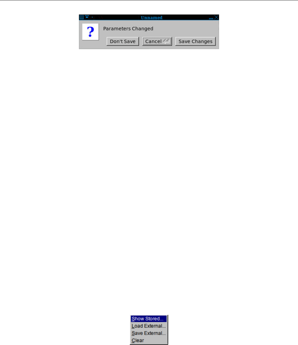
Yoshimi Software Synthesizer 4.2 Menu / Instruments
Figure 23: Yoshimi Menu, Exit
4.2 Menu / Instruments
The Yoshimi Instruments menu lets one select instruments and work with banks of instruments. Yoshimi
stamps instrument XML files with its own major and minor version numbers so it is possible to tell which
version created the files, or whether they were created by ZynAddSubFX.
While the Instrument Menu allows for the management of parts, the Part Edit dialog, described
in Section 9.3 ”Bottom Panel Instrument Edit” on page 141, is where one would start for the the creation
of a new part/instrument.
When opening an instrument bank one can now tell exactly which synth engines are used by each
instrument. This is represented by three pale background colours:
•Red: ADDsynth
•Blue: SUBsynth
•Green: PADsynth
These new colored engine backgrounds aren’t just pretty. They give real information about expected
processor load, and time taken to be ready when loaded:
•Processor Load, low to high: PAD,SUB, then ADD.
•Time to initialize, low to high: SUB,ADD,PAD.
If the instruments are kits they scanned to find out if any member of the kit contains each engine.
This scanning is duplicated in the current part, the mixer panel for the currently loaded instruments, and
in the Instrument Edit window the same colors highlight the engine names when they are enabled with
the check boxes.
The following sub-menus are provided, as shown in Figure 24 ”Yoshimi Menu, Instruments” on
page 47.
Figure 24: Yoshimi Menu, Instruments
This new version of the Instruments menu is somewhat different than the old version. It is actually
simpler and easier to use, while still offering all of the power of the setting up of instruments in Yoshimi.
1. Show Stored...
47
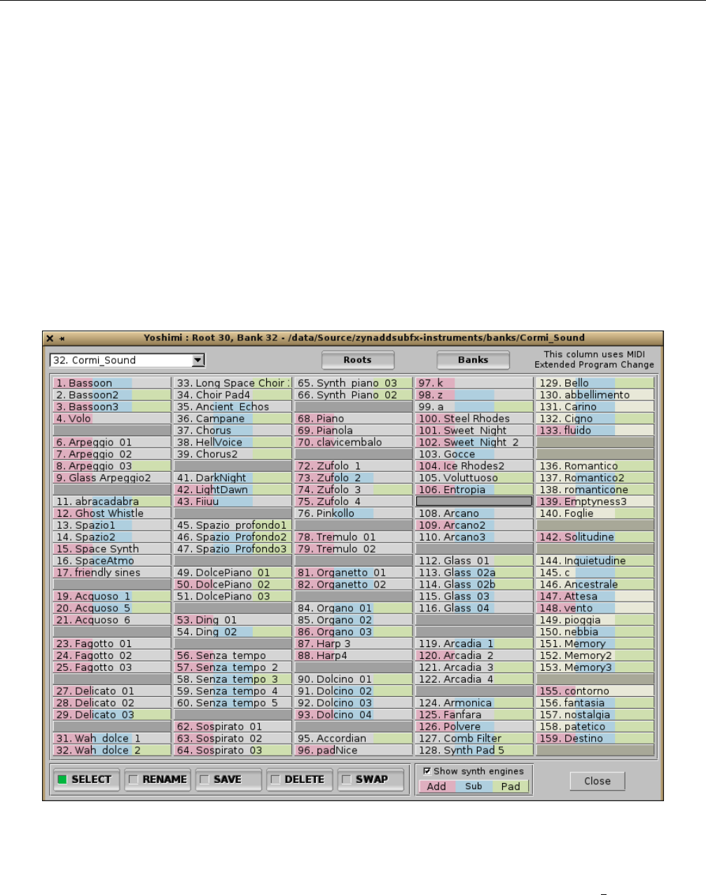
Yoshimi Software Synthesizer 4.2 Menu / Instruments
2. Load External...
3. Save External...
4. Recent Instruments... (not shown in figure)
5. Clear
4.2.1 Menu / Instrument / Show Stored...
Instruments are stored in banks (see Section 21.3 ”Concepts / Banks and Roots” on page 249). The banks
(and current bank setting) are loaded/saved automatically by the program, so one doesn’t have to worry
about saving the banks before the program exits. On program start, the last used bank is loaded. A single
bank can store up to 128 instruments. However, there is space for a number of additional instruments in
the bank, the extended-program section, to allow up to 160 instruments in a bank.
When the Show Stored... button is selected, a dialog comes up that shows all of the instruments
present in the currently-selected bank.
Figure 25: Instruments Stored in Current Banks
As Figure 25 ”Show Stored Instruments” on page 48, shows, this is a very complex dialog with a lot
of options. The figure shows a default setup, with the first bank of instruments, 32. Cormi Sound, listed.
If one drops this list down (shown later), one also observes that the banks are numbered in increments of
5, to make it easier for a user to insert his or her own bank(s) of instruments.
48

Yoshimi Software Synthesizer 4.2 Menu / Instruments
The default set of banks are spaced 5 apart only because thats the best-fit for the current number of
banks. If we add more banks in future versions of Yoshimi, then a clean install is likely to have different
spacing, but for an existing setup, the new entries will just be slotted in where they will fit.
Also, if one deletes banks or instruments by some external means, the next time Yoshimi starts, it
will notice their absence and quietly remove their entries.
Note how Yoshimi now shows the color codings for the synth-sections used in each instrument: red
for ADDsynth, blue for SUBsynth, and green for PADsynth.
Also note how the numbers at the beginning of the filenames are used as an ”instrument” or ”pro-
gram” number. These numbers can be used in MIDI Program Change commands.
All of the instrument files (such as 0001-Arpeggio1.xiz) with filenames starting with numbers (no
matter how many digits) will be shown in the corresponding slot number. Those instrument files without
numbers (or larger numbers?) will start with numbers at 129 or above (”Extended Program Change”)
up to 160. One could give them numbers by renaming them outside of Yoshimi, then reloading the bank.
One can also fix unnumbered ones simply by loading them, then resaving them to the same slot. It’s then
probably best to swap them into the main set, if there is space.
Note that MIDI CC (see Section 4.1.3.5 ”Menu / Yoshimi / Settings / MIDI” on page 44) can be set
to access voices from 129 to 160. All the Bank controls in the MIDI settings tab take immediate effect
when set. Bank and program changes can be completely disabled in the settings tab; some hardware
synths don’t play nice with it.
Learning how to use the Instruments dialog is an important way to make instruments easier to
manage, and so this will be a long discussion.
Here is a list of the user-interface items in the instruments/banks dialog:
1. Bank Names
2. Roots
3. Banks
4. Instrument and Bank Matrix
5. SELECT
6. RENAME
7. SAVE
8. DELETE
9. SWAP
10. Show synth engines
11. Close
1. Bank Names. Instruments Bank Name. This item is a drop-down list of the available instrument
banks in the currently-selected root directory. Basically, each bank is a directory name, with a number
prepended. The banks are found under the current root, which is a also a directory name, and is the name
of the parent directory of a set of banks. Here is the Bank Names drop-down list for the default setup,
which has the default banks provided by the basic Yoshimi installation.
49
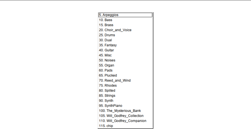
Yoshimi Software Synthesizer 4.2 Menu / Instruments
Figure 26: A Sample Bank List
And here is the directory listing associated with it, in the order produced by the UNIX/Linux ls -1
(list single-column) command (shown in two columns to save space):
Arpeggios Pads
Bass Plucked
Brass Reed_and_Wind
chip Rhodes
Choir_and_Voice Splited
Drums Strings
Dual Synth
Fantasy SynthPiano
Guitar The_Mysterious_Bank
Misc Will_Godfrey_Collection
Noises Will_Godfrey_Companion
Organ
The directories (banks) shown above come from the default root when Yoshimi and its data files are
installed:
/usr/share/yoshimi/banks
If one installed Yoshimi by building the source code, then this directory is:
/usr/local/share/yoshimi/banks
Note that the directory that holds the banks is shown in the title bar. Another good source of banks,
if one installs ZynAddSubFX, is:
/usr/share/zynaddsubfx/banks
50

Yoshimi Software Synthesizer 4.2 Menu / Instruments
Note that there are only 128 Yoshimi banks supported in a Yoshimi root. If the list of banks takes
up about half of the available slots, it might be time to move some of those banks to a new root directory.
The numbers in the drop-down list are generated by Yoshimi the first time it sees a new root path
or a new bank within the root path. Once set, these numbers will never change unless one actually moves
them around (using the SWAP button).
The bank number is also the MIDI ID for the bank; one can be sure that it will always be there for
bank changes, no matter how many banks are added later. Yoshimi always lists the banks in ID order,
not alphabetical order, so one can group them sensibly and permanently. However, at first-time creation
Yoshimi sets the IDs in alphabetical order and tries to space them evenly over the range to provide some
wiggle room. Selecting one of the items in this drop-down list selects the bank and loads it into the Banks
dialog.
Right-clicking or left-clicking on a bank in the drop-down list causes the instrument list of the previous
bank to be replaced by the instrument list of the newly-selected bank.
2. Roots. Instruments Roots Button. Shows a list of directories that can serve as ”root” directories. The
”Bank Root Paths” dialog discussed in Section 4.3.5 ”Menu / Patch Sets / Patch Bank Roots” on page 60in
Figure 32 ”Show Patch Banks” on page 57, shows the system root (e.g. /usr/share/yoshimi/banks) and
a user’s home location for his/her banks and roots.
3. Banks. Banks Button. This item brings up a Banks dialog showing all of the banks present in the
current root. It is an alternative to using the Bank Names drop-down list to select a bank. It is also a
way to reorganize and renumber the banks without using the Linux console or a file-explorer application
to do so.
4. Instrument and Bank Matrix. Instruments Bank Matrix. Shows the instruments that are in the
currently selected bank.
The next few items are selector buttons that determine what happens when one clicks on an instru-
ment name.
5. SELECT. Instruments SELECT. When this button is selected, then clicking on an instrument
selects that instrument as the instrument for the current Part active in the main window. In the main
window of Yoshimi, that instrument name will appear in the currently-selected Part. If Yoshimi is writing
to a console window then each part, when clicked, will be shown:
yoshimi> Loaded 64 "Hyper Organ1" to Part 1
Loaded 65 "Hyper Arpeggio" to Part 1
Loaded 10 "Arpeggio11" to Part 1
Loaded 41 "Soft Arpeggio4" to Part 1
Loaded 67 "Glass Arpeggio1" to Part 1
6. RENAME. Instruments RENAME. When this button is selected, then clicking on a bank brings
up a small dialog to rename the clicked-on bank. However, one will see the following warning message if
trying to rename a file that is in a directory not modifiable by normal users:
! Could not rename instrument 39 to Soft Arpeggio5 [Close]
Note that, as soon as this operation is done, the auto-selector (green check-box) moves back to the
SELECT button.
51

Yoshimi Software Synthesizer 4.2 Menu / Instruments
7. SAVE. Instruments SAVE. When this button is selected, then clicking on a bank saves the instru-
ments as currently configured. A prompt like the following will appear:
? Overwrite the slot no. 43 ? [No/Yes]
However, if one answers yes, and the instrument is in a non-modifiable directory, then one will see
the following error message:
! Could not save to this location [Close]
8. DELETE. Instruments DELETE. Selecting this button and clicking an empty bank entry does
nothing. Selecting this button and clicking an existing bank entry brings up a small dialog asking one if
this bank is really to be deleted.
? Clear the slot no. 68? [No/Yes]
However, if one answers yes, and the instrument is in a non-modifiable directory, then one will see
the following error message:
! Could not clear this location [Close]
9. SWAP. Instruments SWAP. Selecting this button, then selecting one instrument, and then another,
swaps the numbering and postion of the selected instruments. However, one might also experience the
following warning message:
! Could not swap these locations [Close]
Note that all of the above error messages are also shown in the console, if it is where Yoshimi is
running. For example:
40 Failed to remove /usr/local/share/yoshimi/banks/Arpeggios/0041-Soft
Arpeggio3.xiz Permission denied
10. Show synth engines. If enabled, then the usage of each of the Yoshimi synthesis engines is
indicated by color coding, as shown in the figure above.
11. Close. Closes the window.
4.2.2 Menu / Instrument / Load External...
This menu entry simply brings up a file dialog, allowing the user to navigate to an arbitrary directory,
and then to a solitary instrument file (*.xiz), and load it into the current Part.
52
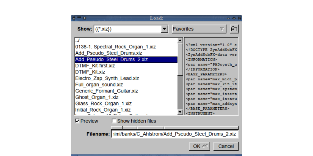
Yoshimi Software Synthesizer 4.2 Menu / Instruments
Figure 27: Instruments, Load External
These ”xiz” files are normally found in a banks directory, but this operation allows access to instru-
ments that are not located in a bank.
•If you load an external instrument file with no internal name, you’ll be shown the file leafname.
•If you load an external instrument file with the name Simple Sound, you’ll be given the name No
Title.
•If you load a patch set that has unnamed instruments, or ones with the name Simple Sound, those
will be given the name No Title.
This dialog has a number of user-interface elements to discuss:
1. Show
2. Favorites
3. Create a new diretory
4. Instrument List
5. XML Preview
6. Preview
7. Show hidden files
8. Directory Bar
9. Filename
10. OK
11. Cancel
These elements are used in a number of different places in Yoshimi. Therefore, we will explain them
all once, here.
1. Show. Show types of files. This item shows a file filter for selecting instrument files. The types of
filters are as follows (screen shot not available):
1. ({*.xiz})(compressed XML files)
53
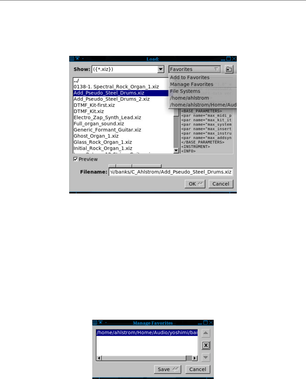
Yoshimi Software Synthesizer 4.2 Menu / Instruments
2. All Files (*)
3. Custom Filter
2. Favorites. Favorite directories. Provides a list of options and favorite directories in which to find
instrument files.
Figure 28: Manage Favorites Drop-Down List
1. Add to Favorites
2. Manage Favorites
3. File Systems
4. (current favorite directories)
Add to Favorites simply adds the currently selected directory shown in the instrument list to the
list of favorites.
To add favorites in the file dialog, navigate to the desired directory. Then click Favorites, and select
Add to Favorites.
Once one has a number of favorites set up, there is a Manage Favorites that can be used. For
example, if one needs to get rid of a directory, one can use the Manage Favorites dialog, shown in
Figure 29 ”Manage Favorites Dialog” on page 54below, to do that.
Figure 29: Manage Favorites Dialog
File Systems Provides a list of all file systems starting at root (”/”). This list can be pretty confusing,
54
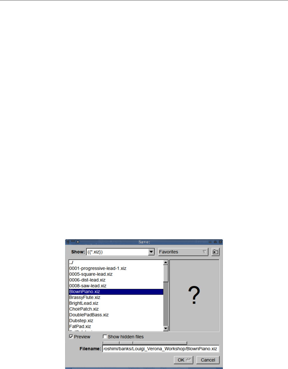
Yoshimi Software Synthesizer 4.2 Menu / Instruments
with a lot of entries. But note that one navigates to (”/”), and from there to /usr/share/yoshimi/banks
to get easy access to all the instruments that are preinstalled with Yoshimi. Generally, one will want to
use only Add to Favorites and Manage Favorites.
3. Create Directory. Creates a New Directory. This little symbol brings up a small ”New Directory?”
dialog (not shown here, it is very simple and stock) into which one can type a directory name to be added
to the current directory of the instrument list.
4. Instrument List. Provides a list of the instrument files available in the current directory. Also shown
are sub-directories (if available) that might contain more instruments, and a (”../”) entry to navigate to
the parent directory.
5. Preview. If one thinks the preview feature is not useful, uncheck this check-box. so that one doesn’t
see the preview window. As a bonus, one can see more of a long instrument file-name.
6. Preview pane. XML Preview. This box can show the beginning of the XML data of an instrument
file. Bug: The XML preview feature shows the XML only if the XML is not compressed.
7. Show hidden files. Shows file that are hidden. Not sure how useful this feature is; who would hide
aYoshimi instrument file?
8. Directory Bar. Provides an alternate way to move up through the directory structure. Click on
each of the small bevelled rectangles to move around in the directory hierarchy.
9. Filename. File Name. Provides the full path specification for the instrument file.
10. OK/Cancel. We don’t really need to discuss the OK and Cancel buttons, do we? OK, we’ll
cancel that discussion.
4.2.3 Menu / Instrument / Save External...
This menu entry simply brings up a file dialog, allowing the user to navigate to an arbitrary directory,
and then save the current Part to a solitary instrument file (*.xiz).
Figure 30: Instruments, Save External
55
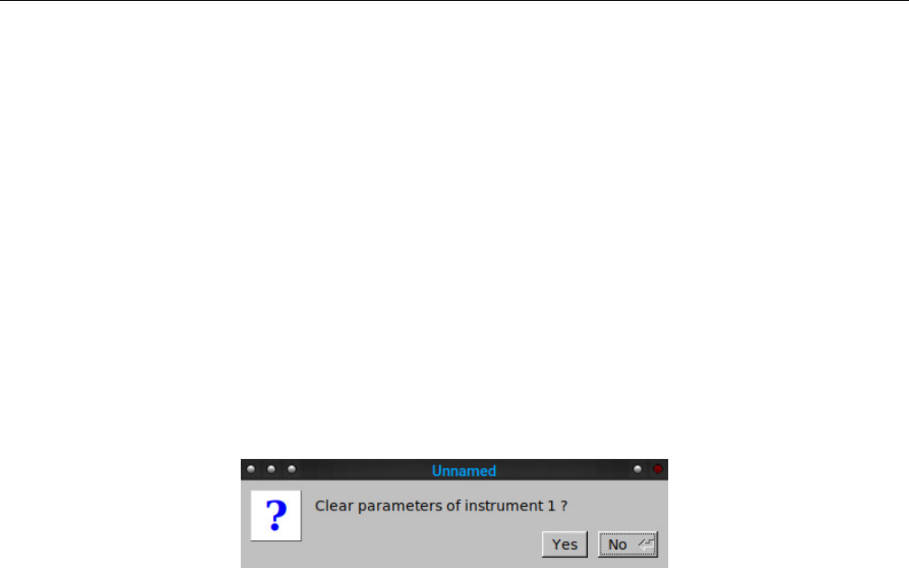
Yoshimi Software Synthesizer 4.2 Menu / Instruments
This dialog is very similar to the Load External dialog. Note the large question mark in the XML
preview, indicating a compressed XML file. If uncompressed, then an XML text preview will be shown.
The instrument save action saves only what is essential to the instrument, and not the part it may
be sitting in. If there have been no changes in the instrument, then a Nothing to save! dialog appears.
4.2.4 Menu / Instrument / Recent Instruments...
This menu brings up a simple window with a list of the most recent instruments that have been selected.
A single-click on the desired instrument will load it.
4.2.5 Menu / Instrument / Clear
This menu entry simply clears the instrument that is loaded into the current Part. This converts the
instrument to a Simple Sound patch. This menu entry brings up a prompt to clear the parameters of the
instrument that is currently loaded in the current part.
Figure 31: Clear Instrument Dialog
No is now the default action.
4.2.6 Menu / Instrument / Misc Notes
There are still many Yoshimi/ZynAddSUbFx instruments out there with no internal title. This fact
applies to both external files and instruments in banks, and means that, once loaded, one does not know
what instruments one has. So now, if the internal name is missing, Yoshimi will use the leaf-name of the
file. When one saves an instrument to a bank slot, it will get a filename with the internal name as the
leaf-name. When one saves an instrument to an external file, you will first be offered the internal name
and in the current directory, but you can change it if you wish.
The part and mixer name fields will always show the (possibly adjusted) internal name regardless
of the external filename, which could easily have been changed at some time. The instrument banks
will always show the file’s leaf-name, so it more-or-less matches external files (what one sees from a file
display). As soon as one edits an instrument, if it was Simple Sound, the name will be changed to No
Title.Yoshimi generally won’t let one rename an instrument to Simple Sound.
Default instruments are never saved, not even in patch sets and states, but if the parts are activated,
that fact is saved; it’s a part feature, not an instrument one.
Patch sets will save all other instruments regardless of whether they are activated or not.
While testing all these features, Will created a new multi-part instrument kit. It’s now in the Com-
panion set and is called Pad Kit.
56
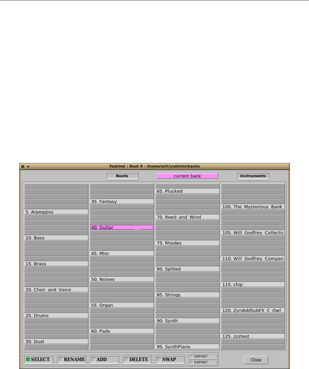
Yoshimi Software Synthesizer 4.3 Menu / Patch Sets
4.3 Menu / Patch Sets
This new menu entry is part of the very nice reorganization and simplification of the handling of roots
and banks in the new Yoshimi. The Patch Sets menu replaces the old Parameters menu. Do you like
the new name? The patch set saves all of the settings, including effects and instruments. Patch sets will
save all other instruments regardless of whether they are activated or not. Default instruments are never
saved, not even in patch sets, but if the parts are activated that fact is saved. It is a part feature, not an
instrument feature.
Yoshimi stamps its configuration XML files with its own major and minor version numbers so it is
possible to tell which version created the files, or whether they were created by ZynAddSubFX.
The main dialog is somewhat similar in layout and function to the dialog shown in Figure 25 ”Show
Stored Instruments” on page 48, for managing instruments in a selected bank.
4.3.1 Menu / Patch Sets / Show Patch Banks...
The Banks window has had some button shuffling, and one can import and export banks as well.
Figure 32: Show Patch Banks
Here is a list of the user-interface items in the patch-banks dialog:
1. Roots
57

Yoshimi Software Synthesizer 4.3 Menu / Patch Sets
2. current bank
3. Instruments
4. Bank Matrix
5. SELECT
6. RENAME
7. SAVE
8. DELETE
9. SWAP
10. IMPORT
11. EXPORT
12. Close
1. Roots. Show Patch Banks, Root Directories. To add a bank root path, delete a bank root path, or
manage bank root path, press this button. The result is somewhat similar to a file dialog, and is described
in detail in Section 4.3.5 ”Menu / Patch Sets / Patch Bank Roots” on page 60, later in this sub-chapter.
2. current bank. This item is highlighted in pink, and the bank that is actually the current bank is
also highlighted in pink. There is no action associated with this user-interface element; it merely indicates
the currently-selected bank.
3. Instrument. This button brings up an instruments window similar to the one shown in Figure 25
”Show Stored Instruments” on page 48, which shows the instruments collected in the currently-selected
bank. Clicking on a bank in the dialog also brings up the instruments window.
4. Bank Matrix. This view shows all of the banks available in the current root. Left-clicking on a
bank in the dialog brings up the Instruments window for that bank. Right-clicking on a bank in the dialog
brings up the Instruments window for that bank, but also closes the banks window, to reduce clutter.
5. IMPORT. There are a number of benefits to using the IMPORT/EXPORT buttons rather than
dealing with the directories externally. One has far greater control where things go when importing, and
it’s much easier to identify the bank to export.
When importing or exporting, Yoshimi refuses to overwrite exisiting banks or directories. That is a
flat refusal for exporting, but for importing it will add a numeric suffix to the name.
Importing will copy only in files that Yoshimi understands, but will notify if there were other un-
recognised types in there. Exporting just dumps out the entire bank contents.
There are a number of banks in the wild that contain all sorts of extraneous stuff, usually copyright
notices; one should use only the instrument text fields, provided for exactly that purpose. Oh, and one
bank Will found had subdirectories with pictures, and they weren’t small!
In the main part Instrument Edit window there is a new Default button top right. See Section 9.3
”Bottom Panel Instrument Edit” on page 141.
We hope this encourages people to fill in the Author and Copyright information. To set it up, fill in
the text field as normal, then, while holding down the Ctrl key, click on the button (left or middle mouse
click) . This text will now be stored in one’s Yoshimi configurionat directory, and whenever one creates a
new instrument, just click on the Default button, and the saved text will be filled in.
6. EXPORT. Export of banks is described in the previous section.
The buttons SELECT,RENAME,SAVE,DELETE, and SWAP behave similarly to the same
buttons in the Instruments window, as described in the discussion at Section 4.2.1 ”Menu / Instrument
/ Show Stored..” on page 48.
58
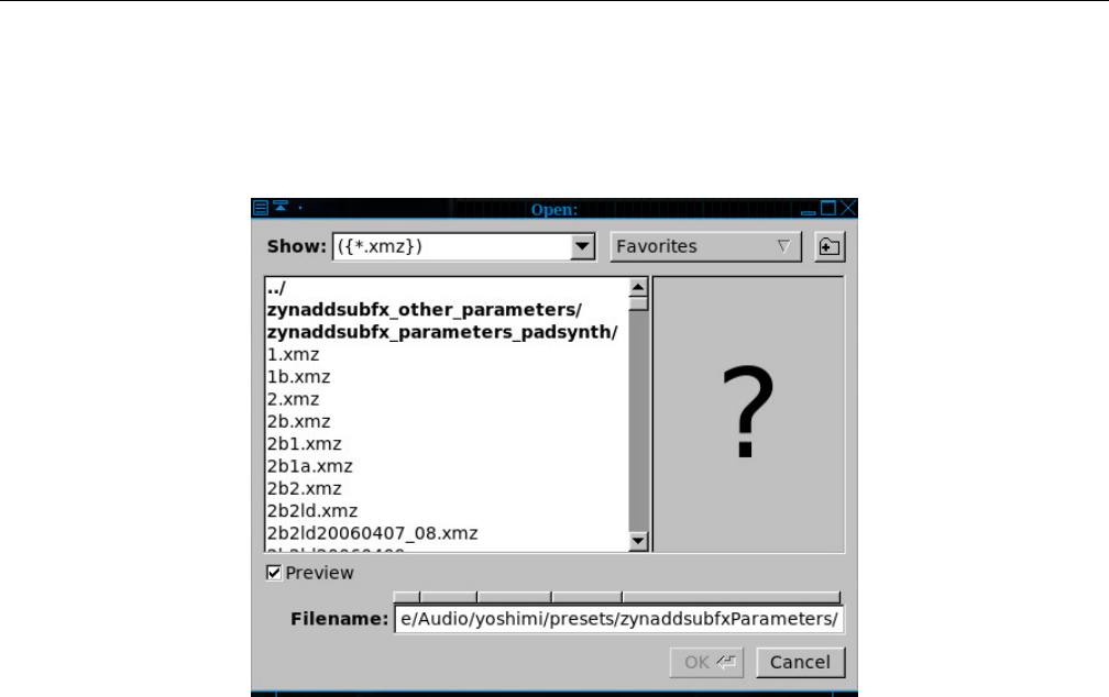
Yoshimi Software Synthesizer 4.3 Menu / Patch Sets
4.3.2 Menu / Patch Sets / Load External...
This menu entry simply brings up a file dialog, allowing the user to navigate to an arbitrary directory,
and then to a solitary instrument file (*.xmz), and load it into the current set of parts.
Figure 33: Load Patch Set
These ”xmz” files are normally found in a presets directory, but this operation allows access to
banks that are not located in a particular root.
When an ”xmz” file is loaded, all of the instruments it contains are loaded sequentially into the Parts.
Thus, a number of instruments are loaded at once. So, a patch set is a list of instruments that are related
by being necessary for a given tune, rather than by being located in a particular bank.
4.3.3 Menu / Patch Sets / Save External...
This menu entry simply brings up a file dialog, allowing the user to navigate to an arbitrary directory,
and then save the current Part to a solitary instrument file (*.xiz).
In patch sets, Yoshimi will save named-but-disabled patches. Currently, ZynAddSubFX does not, so
be aware when transferring data between the two synthesizers.
59
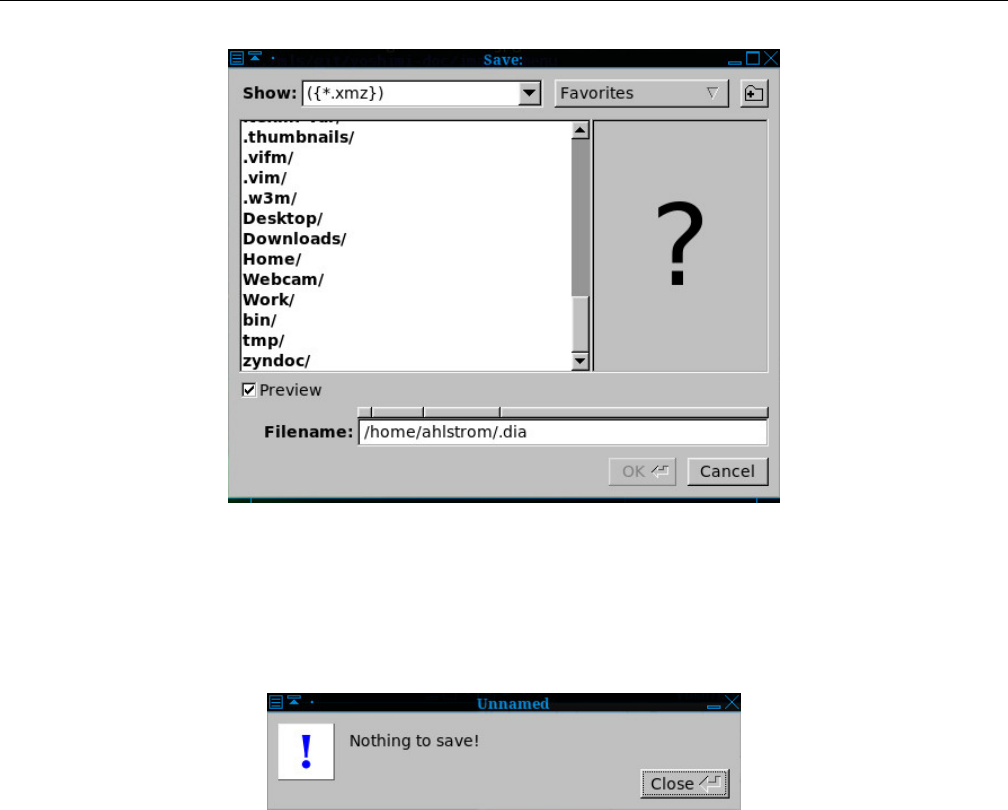
Yoshimi Software Synthesizer 4.3 Menu / Patch Sets
Figure 34: Save Patch Set
Patch set saves include everything that is not part of the main configuration, and so saved patch
sets includes Master Volume and Detune Part destinations, Humanise, and more. If nothing has
changed, then the following dialog is shown.
Figure 35: Patch Set, Nothing to Save
4.3.4 Menu / Patch Sets / Recent Sets
This menu entry brings up a dialog box with a list of the recent patch sets that have been loaded. This
item makes it easy to move around one’s frequently-used banks.
4.3.5 Menu / Patch Sets / Patch Bank Roots
Yoshimi (as installed by Debian Linux) provides a default bank at /usr/share/yoshimi/banks. To add
one’s own directory, click on the Roots button. It brings up the following dialog.
60
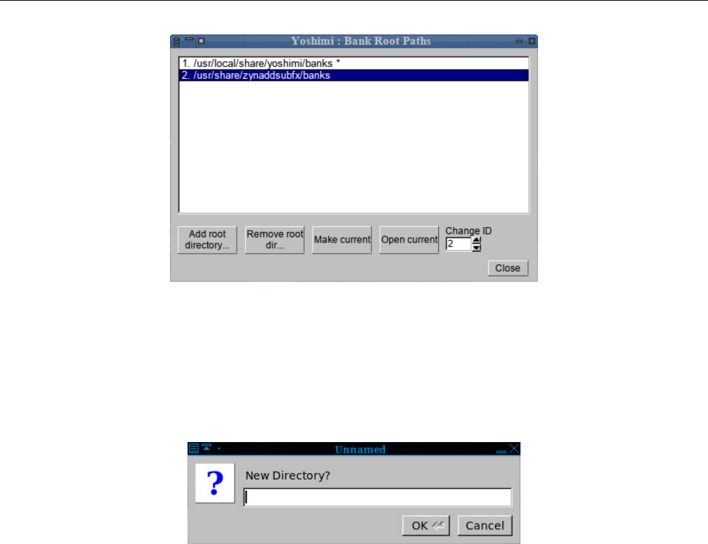
Yoshimi Software Synthesizer 4.3 Menu / Patch Sets
Figure 36: Bank Root Paths
This dialog has a number of buttons, some of which will be disabled if no directory in the list is
selected.
Then click on the ”Add root directory...” button. In the file dialog that appear, one can use the
Create Directory button to make a new directory, if desired:
Figure 37: New Root Directory?
Otherwise, once can add an existing directory to the list.
1. Add root directory.... Bank Root Paths, Add Root Directory.
Once selected, one will see that /usr/share/yoshimi/banks or /usr/local/share/yoshimi/banks
is marked with an asterisk. One can select the new root directory via the file dialog that appears, and
then make it the current root by clicking the Make current button. Then the Banks dialog will show
all the banks in that directory, one bank per subdirectory (each subdirectory ”is” a bank).
2. Remove root directory.... Bank Root Paths, Remove Root Directory. If a path is selected, then
this button is active, and can be used to delete the selected path from the ”root paths” list.
3. Make current. Bank Root Paths, Make Current. This button marks the currently-selected path as
the ”current root” path.
4. Open current. Bank Root Paths, Open Current. This button opens the current root path. (Does
this work?)
5. Change ID. Bank Root Paths, Change ID. This ID can be used to make the bank selectable via
an extended MIDI control.
Values: 0* to 127
61
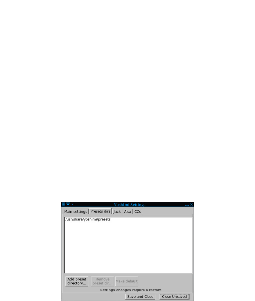
Yoshimi Software Synthesizer 4.4 Menu / Paths
4.4 Menu / Paths
This menu entry provides a more direct way to set up the Bank Root and the Presets directories. It
contains the following items:
1. Bank Root Dirs.... The Paths Bank Root Dirs dialog is described in Section 4.3.5 ”Menu / Patch
Sets / Patch Bank Roots” on page 60, which shows Figure 36 ”Bank Root Paths” on page 61, and
describes this dialog in full.
2. Preset Dirs.... The Yoshimi preset directories are the locations where presets can be found. See
below for details.
The Yoshimi preset directories are the locations where presets can be found. When first installed,
the system preset directory is one of the following, depending on whether Yoshimi was installed via a
package manager or via source code:
/usr/share/yoshimi/presets
/usr/local/share/yoshimi/presets
The user can provide additional directories for the presets, up to a limit of 128 directories (the same
limit as for roots and banks). These directories are useful for containing copies of the system presets that
one can modify safely, and for providing custom presets designed by the user.
The following items are provided by the preset directory settings:
1. Preset list
2. Add preset directory...
3. Remove preset directory...
4. Make default
5. Save and Close
6. Close Unsaved
Figure 38: Yoshimi Preset Dirs Dialog
1. Preset list. This interface element contains a list of preset directories. By default, the only directory
present is the installed preset directory. For example, /usr/share/yoshimi/presets.
62
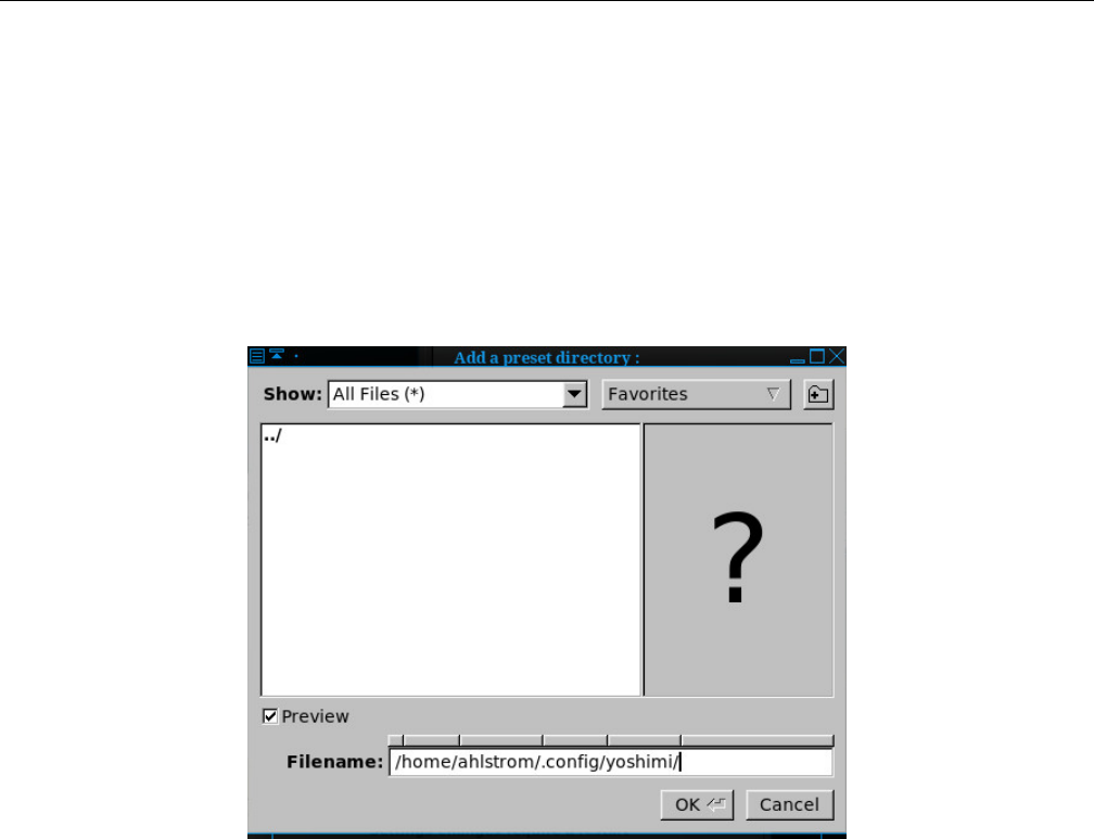
Yoshimi Software Synthesizer 4.5 Menu / Scales
Tip: If there is no directory in this dialog, then one must add one, otherwise there is no place to
store the presets. So make this one of the first items specified when first running Yoshimi!
Another example would be this project; let YOSHIMI-DOC be the directory where this project is
stored. Then one can add YOSHIMI-DOC/config/yoshimi/presets to this list, using the button described
next.
2. Add preset directory.... Use this button and dialog to add a preset directory to the list, for easy
access.
Press the Add preset directory... button, revealing the following dialog.
Figure 39: Add a Preset Directory
Navigate to the desired directory, select it, and press the Ok button. (There is no need to press the
Save and Close button; the directory is added as soon as OK is clicked. However, one tends to want to
click it anyway, to be sure.) Important: Restart Yoshimi to use the preset directory.
3. Remove preset directory.... Select one of the preset directories in the preset list, then press this
button to remove the preset directory from the list of preset directories. It is removed immediately, with
no need to confirm the deletion, click an OK button, or click a Save button.
4. Make default presets. Make Default Presets Directory. Select one of the preset directories in the
preset list, then press this button to make the preset directory the default preset directory. It should be
a directory for which one has write permissions. By default, it is ~/.config/yoshimi/presets.
4.5 Menu / Scales
Yoshimi is a microtonal synthesizer, and is capable of a wide range of microtonal scales. Improvement
to its features and the accuracy of the scales have been made in the 1.5.0 series of Yoshimi. Scales are
discussed in detail in Section 5”Scales” on page 65.
63
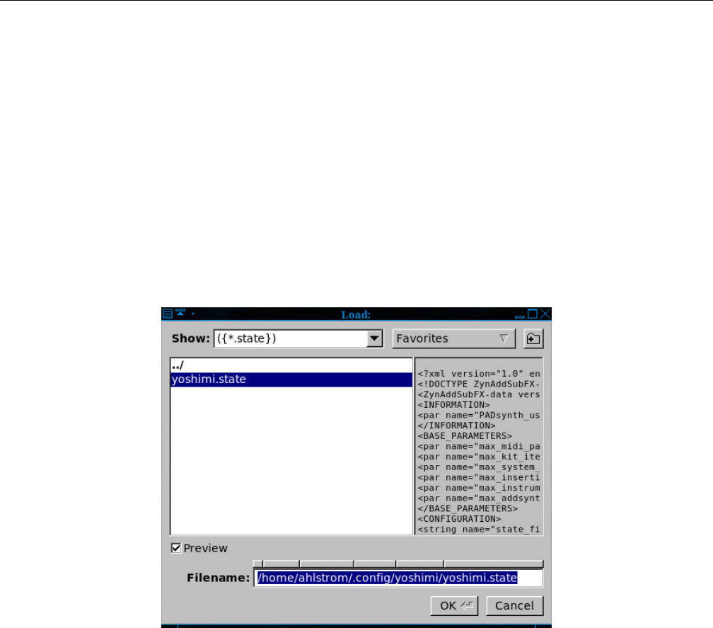
Yoshimi Software Synthesizer 4.6 Menu / State
4.6 Menu / State
Yoshimi state is saved in files with the extension .state. These files are also XML files.
Yoshimi ”state” will include the system settings, as well as all patches. Some of these settings (such
as Oscillator Size) can only be realised on a reload if loading via the command line at startup.
1. Load
2. Save
3. Save as Default (new, not yet shown)
4. Recent States...
State files were normally stored in the user’s .config/yoshimi/yoshimi.state file, but now Yoshimi
offers the user’s home directory instead.
1. State Load. Provides a way to load a previously-saved Yoshimi state file.
Figure 40: Yoshimi Menu, State Load
This item is a standard Yoshimi file dialog. Note that XML text is shown in the preview pane, but,
if XML compression is set, then a large question mark is all that would be shown.
2. State Save. Provides a way to save a new or modified Yoshimi state file.
64
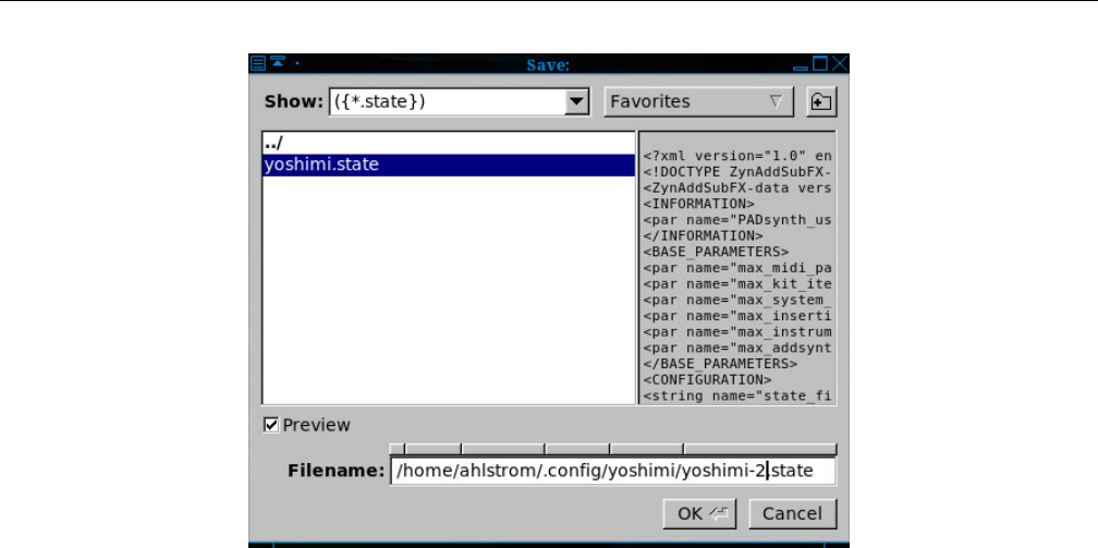
Yoshimi Software Synthesizer
Figure 41: Yoshimi Menu, State Save
This item is a standard Yoshimi file dialog.
3. Save as Default. This item simply makes the current state the new default state when starting
Yoshimi. This item is effective only if the Start With Default State option is checked in Yoshimi /
Settings. This item is also exceptional is it will not appear in the history list, and so will not be offered
as a normal load.
4. Recent States. This item brings up a list of states to select. The Recent States dialog will not
come up if there are no states that have yet been managed.
5 Scales
Yoshimi is a microtonal synthesizer, and is capable of a wide range of microtonal scales. Many improve-
ments have been made to the scales, including the user-interface, performance, accuracy of calculations,
and adherence to the Scala ([15]) specification. in version 1.5.2 and above. At the request of users, since
version 1.5.8 some controls have been made accessible to MIDI-learn, and these have the familiar pale
blue border. For users of the LV2 plugin, any changes in scale settings are reported back so that the plugin
host can be aware of the change.
5.1 Scales / Command Line
One can now fully control scales from the CLI. For tunings, either ratios or floating point numbers can
be entered. Ratios are in the form n1/n2 to a maximum of normal integer range. If just a numerator is
set, it will be regarded as n/1. Floating point numbers must include the decimal point and at least one
digit (or zero) on either side. The numbers are padded out with leading and trailing zeros in the form
nnnn.nnnnnn.
In keyboard maps, non-sounding notes should be entered as an ’x’ instead of the key number.
CLI tunings and keymaps are entered in CSV format. Tuning:
65
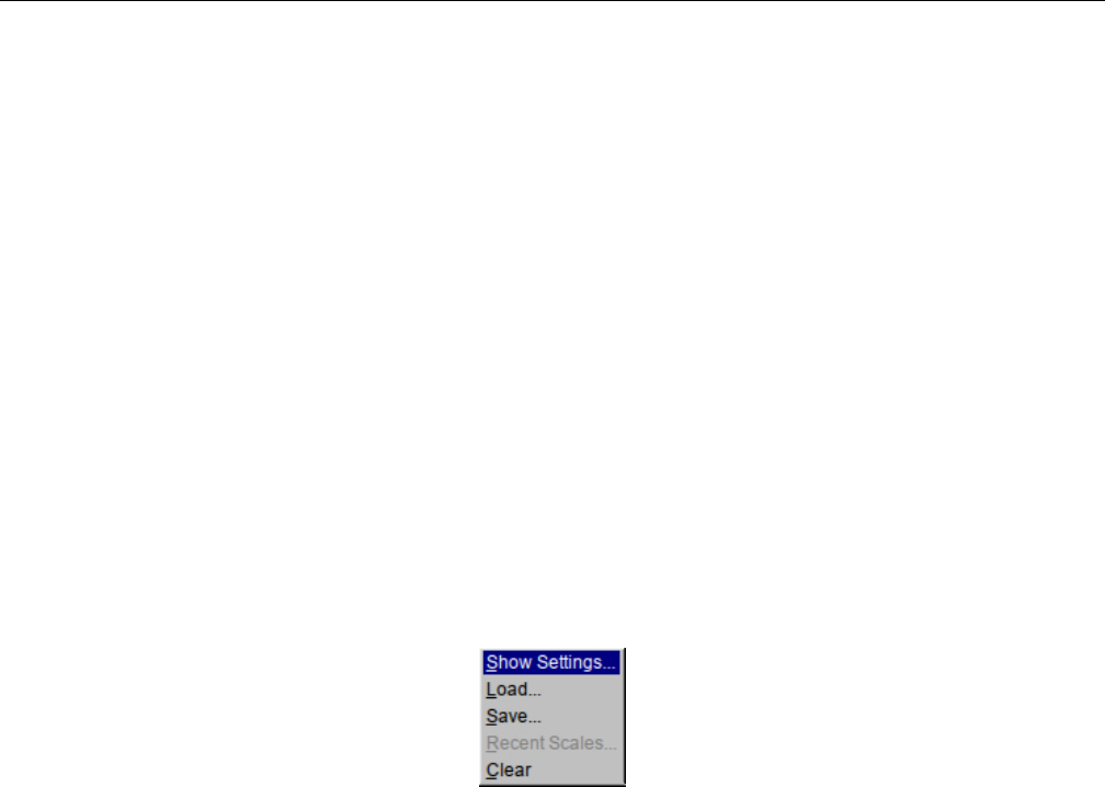
Yoshimi Software Synthesizer 5.1 Scales / Command Line
0076.049000, 0193.156860, 0310.264710, 5/4, 0503.421570,
0579.470570, 0696.578430, 25/16, 0889.735290, 1006.843140,
1082.892140, 2/1
Keymap:
0, 1, 2, 3, x, 5, 6, 7, x, 9, 10, 11
The tuning/keymap sizes are generated internally by counting the number of entries in the strings.
When saving scales, for floating point numbers, Yoshimi includes the text it was derived from. This
has accuracy benefits, but also reassures less experienced users, because the values they enter won’t seem
to change on re-loading. The stored value is still saved for backward compatibility with older versions of
Yoshimi.
Scale shift provides an offset to the scale start position, and only makes a difference in uneven interval
sizes.
Normally (for the even tempered scale) the scale starts on ’A’, and, as the intervals are all identical,
changing the octave start will make no difference. However, if one has (say) a 5-note pentatonic scale, the
intervals will be very different and the scale shift will effectively determine the key of the scale.
Figure 42: Yoshimi Menu, Scales
1. Show Settings...
2. Load...
3. Save...
4. Recent Scales...
5. Clear
66
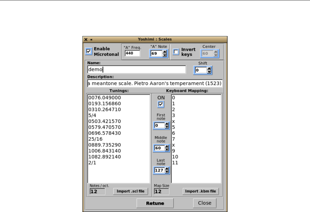
Yoshimi Software Synthesizer 5.2 Scales / Show Settings
5.2 Scales / Show Settings
Figure 43: Yoshimi Menu, Scales Settings
5.2.1 Scales Basic Settings
This item controls the micro-tonal capabilities of Yoshimi and some other settings related to tuning. The
last entry in the tunings list represents one octave. All other notes are deduced from these settings.
1. Enable Microtonal
2. ”A” Freq.
3. ”A” Note
4. Invert Keys
5. Center
6. Name
7. Shift
8. Comment
9. Tunings
10. Retune
11. Keyboard Mapping
12. ON
13. First note
14. Middle note
15. Last note
16. nts./oct.
17. Import .scl file
67

Yoshimi Software Synthesizer 5.2 Scales / Show Settings
18. Map Size
19. Import .kbm file
20. Close
1. Enable Microtonal. Enable Microtonal Scales. When disabled, the synthesizer will use equal-
temperament, 12 notes per octave. Otherwise, one can input any scale one desires.
Values: Off*, On
2. ”A” Freq. Frequency of the ”A” Note. Sets the frequency of the ”A” key. The standard is 440.0
Hz.
Values: 440*
3. ”A” Note. Sets the MIDI Value of the ”A” Note.
Values: 0 to 127, 69*
4. Invert Keys. Allows the keys to be inverted, so that higher-valued keys play lower notes.
Values: Off*, On
5. Center. Center for Inverted Keys. This is the center where the notes frequencies are turned upside-
down if Invert keys is enabled. If the center is 60, the note 59 will become 61, 58 will become 62, 61 will
become 59, and so on.
Values: 0 to 127, 60*
6. Name. Name of the Mapping. For example, the default mapping is called ”12tET”.
7. Shift. Key Shift. Shift the scale. If the scale is tuned to A, one can easily tune it to another key.
Values: -63 to 64, 0*
8. Comment. Comment for Key Mapping. Provides a comment or a description of the scale. By
default, this is ”Equal Temperament 12 notes per octave”.
9. Tunings. Tunings. Here one can input a scale by entering all the tunings for one octave. One can
enter the tunings in two ways:
1. As the number of cents (1200 cents=1 octave) as a float number like ”100.0”, ”123.234”
2. As a proportion like ”2/1” which represents one octave, ”3/2” a perfect fifth, ”5734/6561”. ”2/1”
is equal to ”1200.0” cents.
The default is a series of values: 0100.0, 0200.0, ..., 1100.0, 2/1.
10. Keyboard Mapping. The items related to the Keyboard Mapping are discussed separately in
the next section.
11. Retune. Retune button. This button retunes the synthesizer according to the settings of the
Tunings and Keyboard Mapping lists. The Retune button is needed if one changes any of the actual
scale settings. However, it’s not needed for key mappings or any other controls, all of which operate
immediately.
12. nts./oct. Notes Per Octave. This value is affected by changes to the Tunings mapping.
Values: 12*
13. Import .SCL file. Import Scala files. Scala is a powerful application for experimentation with
musical tunings (intonation scales, micro-tonal,...etc.). From its home page [15], one can download more
than 2800 scales which one can import directly into Yoshimi. Note that the zip file must be unzipped
with the -aa (”autoconvert”) option. However, we have converted it to a a much smaller tar file (it crams
68
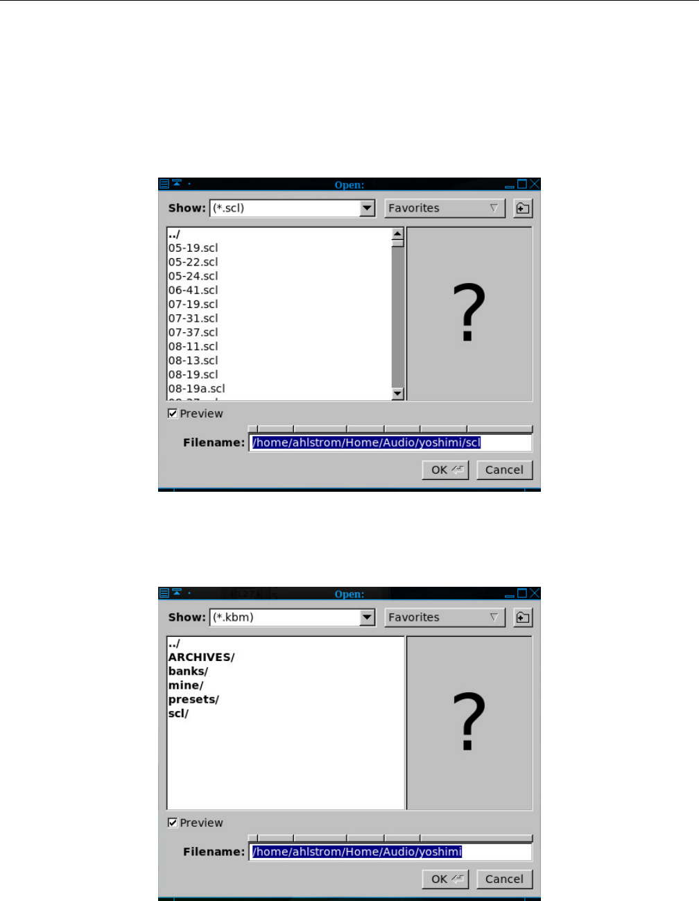
Yoshimi Software Synthesizer 5.2 Scales / Show Settings
18 Mb of files into an sub-500 Kb file), which can be untarred directly into one’s configuration directory
to create a ~/.config/yoshimi/scales directory chock full of scales.
$ cd ~/.config/yoshimi/
$ tar xf yoshimi-scales.tar.xz
Note that a Scala file cannot be loaded directly. It must be imported.
Figure 44: Yoshimi Menu, Scales, Import File
This item is a standard file dialog for reading a *.scl file.
Figure 45: Yoshimi Menu, Scales, Import Keyboard Map
69

Yoshimi Software Synthesizer 5.2 Scales / Show Settings
14. Map Size. Map Size. This value is affected by changes to the Keyboard Mapping.
Values: 12*
15. Import .kbm file. This item is a standard file dialog for reading a *.kbm file.
16. Close, Scales Dialog.
5.2.2 Keyboard Mapping
One can set the MIDI keyboard mapping to scale-degree mapping. This is used if the scale has more or
less than 12 notes/octave. One can enable the mapping by pressing the ON check-box.
1. ON
2. First Note
3. Last Note
4. Middle Note
5. Map
6. Map Size
1. ON. This item enables the Keyboard Mapping list.
Values: Off*, On
2. First Note. First MIDI Note Number. Sets the MIDI note value to use for the first note of the
scale. MIDI notes below this value are ignored.
Values: 0* to 127
3. Middle Note. Sets the MIDI note value to use for the middle note of the scale. This is the note
where the scale-degree 0 setting is mapped; the middle note represents the note where the formal octave
starts.
Values: 0 to 127*
4. Last Note. Last MIDI Note Number. Sets the MIDI note value to use for the last note of the scale.
Keys above this value are ignored.
Values: 0 to 127*
5. Map. Scales map. This is the input field where the mappings are entered. The numbers represent
the order (degree) entered on Tunings Input field, with the first value being 0. This number must be
less than the number of notes per octave (since the values start at 0). If one doesn’t want a key to be
mapped, one enters an ”x” instead of a number.
Values: 0 to 11
6. Map Size. Provides the size of the scale-map.
Values: 12
In the current version of Yoshimi, up to 25 recently used scales are now stored in the new history
file (yoshimi.history), and can be quickly reinstalled with a mini-browser in exactly the same way as
patch sets.
70
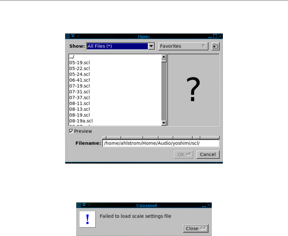
Yoshimi Software Synthesizer 5.3 Scales / Load
5.3 Scales / Load
Figure 46: Yoshimi Menu, Open Scales
If the format of the scales file is not correct, then the following prompt will appear.
Figure 47: Yoshimi Menu, Failed to Load Scales
Note that the loading and saving of scales is fully available in the command-line as well.
5.4 Scales / Save
This dialog opens a stock file-dialog to allow the saving of *.xsz files. If one has imported a scale from
an *.scl file, and one wants direct access to it from the Scales / Recent Scales menu, one must first
save the imported file as an *.xsz files.
Note that the loading and saving of scales is fully available in the command-line as well.
In the past, every time one saved and reloaded a scale, there was a degradation in the accuracy of
the scales. This issue has been fixed, since people are very sensitive to pitch intervals.
5.5 Scales / Recent Scales...
Once a scale file has been loaded (or imported and saved), then it becomes available in this list, for more
convenient access to it.
71

Yoshimi Software Synthesizer 5.6 Scales / Clear
Figure 48: Yoshimi Menu, Recent Scales
5.6 Scales / Clear
This menu entry simply resets the Yoshimi scale back to it default, the twelve-tone equally-tempered
scale.
6 Stock Settings Elements
This section collects all of the settings values and small user-interface items that one will find for audio
parameters in the Yoshimi GUI. Sometimes the labels and tool-tips in the application are a bit too brief
to understand. One will find their full meanings, their tricks, and usage notes in this section. This section
also covers the sub-panels that provide the settings. Many of these sub-panels are used in many places
in Yoshimi, not only as user-interface elements, but as presets that can be saved and load. By describing
the deep details of these sub-panels here, we can refer to them when describing how to set up specific
sounds in Yoshimi. Much of this material comes from http://sourceforge.net/zynaddsubfx/Doc and
has been reorganized and expanded.
6.1 Settings Features
This section notes some minor interface and synthesizer features that may be seen thoughout Yoshimi.
6.1.1 Mouse Features
The right mouse click is used for setting the default value of a control, where it acts like a ”reset” button,
and is also used to bring up the MIDI Learn dialog for controls that can be MIDI-learned.
When traversing window stacks, a right click will close one window as it opens the next. Closing such
a window with the right button will re-open its parent.
6.1.2 Tooltips
Like many applications, Yoshimi provides tooltips to help the user navigate the many controls and data
fields in the user-interface. Many of the controls now have active tooltips that show the current value of the
control when one hovers over it, so one no longer must click the control to see its value (and accidentally
change it at the same time). Many have real-world data units, such as dB,Hz,ms etc.
72

Yoshimi Software Synthesizer 6.1 Settings Features
6.1.3 Title Bars
The title bars of all editing windows display both the part number and the current name of the instrument
one are working on. In the ADDsynth Oscillator Editor, one also sees the voice number of the oscillator
one is editing. Title bars also include the kit entry number if that part has a kit enabled.
6.1.4 Color Coding
A GUI enhancement for Yoshimi 1.3.5 is color-coded identification of an instrument’s use of ADD-,
SUB-, and PAD-synth engines, no matter where in the instrument’s kit they may be. This can be en-
abled/disabled in the mixer panel. It does slow down Yoshimi’s startup, but due to the banks reorgan-
isation (done some time ago) it causes no delay in changing banks/instruments once Yoshimi is up and
running. Some saved instruments seem to have had their ”Info” section corrupted. Yoshimi can detect
this issue, and step over it to find the true status. Also, if one resaves the instrument, not only will the
PADsynth status be restored, but ADDsynth and SUBsynth will be included, allowing a faster scan next
time.
6.1.5 Rotary Knobs
Visual rotary knobs are used for modifying numerical parameters in the user-interface. Horizontal, as well
as vertical, mouse movements will adjust the knob. Mouse clicks also can adjust the knob.
•Coarse Control. When rotated using the left mouse button, the rotary knobs give a coarse control
of the numerical settings of the knob.
•Fine Control. When a knob is rotated using the middle mouse button, the rotary knobs give a
finer control of the numerical settings of the knob.
•Scroll Wheel. One can also use the mouse scroll wheel to adjust rotary controls, which gives
better control than using the mouse pointer.
•Super Fine Control. If the Ctrl key is held at the same time as the wheel is scrolled, the control
is extremely fine.
Note that the right mouse button can be used for setting the default value of a control or for the
initiation of MIDI learn.
•Home Position. A right-click sends the knob to the home position (and sets its value to the home
value). For setting like Pan and Detune it is the middle position; for other settings, it is whatever
the default value is for that setting.
The fact that every control can now be homed with a right mouse click means there is no longer a
need for the few ”Zero” and ”Reset” buttons dotted around, so they are all gone as of version 1.4.0.
6.1.6 Sliders
For both horizontal and vertical sliders, if one holds down the right mouse button, the thumb will go to
it’s default position. The same thing will happen if one clicks on the track with the right button. If on
top of the thumb of the control, it won’t move unless one moves the mouse slightly while right-clicking.
Yoshimi has changed some rotary controls or rollers to sliders. These controls pack better without
looking crowded, are easier to manage, with clearer indication.
73

Yoshimi Software Synthesizer 6.1 Settings Features
6.1.7 Presets
The ZynAddSubFX/Yoshimi concept of presets is very powerful.
Absolutely every user-interface section that has blue Cand Pbuttons can be stored in the presets
directory. That includes entire Addsynth engines! When one looks at the copy/paste buffer, one sees only
items that are relevant to the group that the C/P buttons are in.
As one wants to save, as well as load, these presets, it makes sense to copy all the default ones to a
location such as ~/.config/yoshimi/presets. That makes them fully accessible, but tucked away out
of sight. Yoshimi creates this directory at first time start up. Preset files allow one to save the settings for
any of the components which support copy/paste operations. This is done with preset files (.xpz), which
get stored in the folders indicated by Paths / Preset Dirs.... Note that the number of preset directories
that can be set is limited to 128 (the same as for roots and banks).
6.1.8 Automation
In Yoshimi 1.3.5, a number of existing, as well as new features have come together to give much greater
flexibility (especially for automation) using standard MIDI messages. These are:
1. NRPNs
2. ZynAddSubFX controls
3. Independent part control
4. 16, 32 or 64 parts
5. Vector Control
6. Direct part stereo audio output
1. NRPNs. NRPNs can handle individual bytes appearing in either order, and usually the same with
the data bytes. Increment and decrement is also supported as graduated values for both data LSB and
MSB. Additionally, the ALSA sequencer’s 14-bit NRPN blocks are supported.
2. ZynAddSubFx controls. System and Insertion Effect controls are fully supported, with extensions
to allow one to set the effect type and (for insertion effects) the destination part number.
3. Part control. Independent part control enables one to change instrument, volume, pan, or indeed any
other available control of just that part, without affecting any others that are receiving the same MIDI
channel. This can be particularly interesting with multiply layered sounds. There are more extensions
planned.
4. 16/32/64 Parts. With 32 and 64 parts, it helps to think of 2 or 4 rows of 16. When one saves
a parameter block, the number of parts is also saved, and will be restored when one reloads. By default
each column has the same MIDI channel number, but these can be independently switched around, and
by setting (say) number 17 taken right out of normal access.
In tests, compiling for 64 parts compared with 16 parts increased processor load by a very small
amount when Yoshimi was idling, but this becomes virtually undetectable once one has 8 or more in-
struments actually generating output. In normal use, selecting the different formats makes no detectable
difference, but using the default 16 reduces clutter when one doesn’t need the extras.
5. Vector control. Vector control is based on these parts columns, giving one either 2 (X only) or 4
(X + Y) instruments in this channel. Currently the vector CCs one set up can (as inverse pairs) vary any
combination of volume, pan, and filter cut-off. More will be added. To keep the processor load reasonable
it pays to use fairly simple instruments, but if one has sufficient processing power, it would be theoretically
possible to set up all 16 channels with quite independent vector behavior! Also see Section 16.2 ”Vector
74

Yoshimi Software Synthesizer 6.2 Filter Settings
Dialogs” on page 195, for a discusson of the vector configuration dialog, and Section 16 ”Vector Control”
on page 194, for an in-depth discussion of how vectors work.
6. Direct part audio. Direct part audio is JACK-specific, and allows one to apply further processing
to just the defined part’s audio output (which can still output to the main L+R if one wants). This
setting is saved with parameter blocks. Currently it is only set in the mixer panel window, but it will
also eventually come under MIDI direct part control. Again, to reduce unnecessary clutter, part ports are
only registered with JACK if they are both enabled, and set for direct output. However, once set they
will remain in place for the session to avoid disrupting other applications that may have seen them.
6.2 Filter Settings
This section describes filtering at a high level, in terms of frequency responses and other concepts of
filtering. The end of this section covers a user interface used in filter settings. It is a stock-panel re-used
in other user-interface elements. See Section 6.2.5 ”Filter Parameters User Interface” on page 78, if one
is in a hurry.
Yoshimi offers several different types of filters, which can be used to shape the spectrum of a signal.
The primary parameters that affect the characteristics of the filter are the cutoff, resonance, filter stages,
and the filter type.
Filter stages are the number of times that this filter is applied in series. So, if this number is 1, one
simply has this one filter. If it is two, the sound first passes the filter, and the results then pass the same
filter again. In ZynAddSubFX, the wetness is applied after all stages were passed.
6.2.1 Filter Type
A filter removes or attenuates frequency elements or tones from a signal. Filtering changes the character
of a signal.
The basic analog filters that Yoshimi and ZynAddSubFX offer are shown in Figure 49 ”Basic Filter
Types” on page 76, with the center frequency being marked by the red line. The state variable filters
should look quite similar.
75
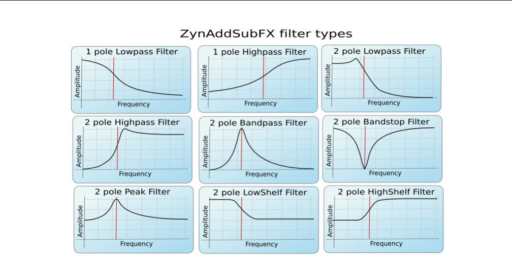
Yoshimi Software Synthesizer 6.2 Filter Settings
Figure 49: Filter Types, Yoshimi/ZynAddSubFX
1. A low-pass filter makes the sound more muffled.
2. A band-pass filter makes the sound more tone-like, and sometimes more penetrating, if the total
energy in the passband is preserved as the bandwidth decreases.
3. A high-pass filter makes the sound seem sharper or more strident.
6.2.2 Filter Cutoff
The filter cutoff value determines which frequency marks the changing point for the filter. In a low pass
filter, this value marks the point where higher frequencies begin to be attenuated.
6.2.3 Filter Resonance
The resonance of a filter determines how much excess energy is present at the cutoff frequency. In Yoshimi
and ZynAddSubFX, this is represented by the Q-factor, which is defined to be the cutoff frequency divided
by the bandwidth. In other words higher Q values result in a much more narrow resonant spike.
The Q value of a filter affects how concentrated the signal’s energy is at the cutoff frequency. The
result of differing Q values are shown in Figure 50 ”Low Q vs. High Q” on page 77. For many classical
analog sounds, high Q values were used on sweeping filters. A simple high Q low pass filter modulated by
a strong envelope is usually sufficient to get a good sound.
76
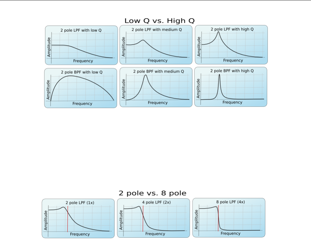
Yoshimi Software Synthesizer 6.2 Filter Settings
Figure 50: The Effect of the Q Value
6.2.4 Filter Stages
The number of stages in a given filter describes how sharply it is able to make changes in the frequency
response. The more stages, the sharper the filter. However, each added stage increases the processor time
needed to make the filter calculation.
Figure 51: The Effect of the Order of a Filter
The affect of the order of the filter can be seen in the figure above. This is roughly synonymous with
the number of stages of the filter. For more complex patches, it is important to realize that the extra
sharpness in the filter does not come for free, as it requires many more calculations to be performed.
This phenomena is the most visible in SUBsynth, where it is easy to need several hundred filter stages to
produce a given note.
There are different types of filters. The number of poles define what will happen at a given frequency.
Mathematically, the filters are functions which have poles that correspond to that frequency. Usually,
two poles mean that the function has more ”steepness”, and that one can set the exact value of the
function at the poles by defining the ”resonance value”. Filters with two poles are also often referred to
as Butterworth Filters.
For the interested, functions having poles means that we are given a quotient of polynomials. The de-
nominator has degree 1 or 2, depending on the filter having one or two poles. In the file DSP/AnalogFilter.cpp,
computefiltercoefs() sets the coefficients (depending on the filter type), and singlefilterout() shows
the whole polynomial (in a formula where no quotient is needed).
77
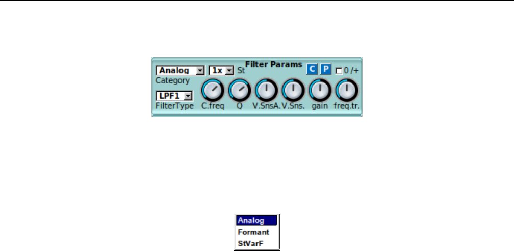
Yoshimi Software Synthesizer 6.2 Filter Settings
6.2.5 Filter Parameters User Interface
Figure 52: Stock Filter Parameters Sub-Panel
The user interface for filter parameters is a small stock sub-panel that is re-used in a number of larger
dialog boxes, as shown in the figure above. This panel has changed slightly with version 1.5.0. Let’s
describe each item of this sub-panel.
Figure 53: Filter Categories, Dropdown Box
1. Category
2. Filter Type
3. C.freq
4. Q
5. V.SnsA
6. freq.tr
7. gain
8. St
9. 0/+
10. C
11. P
1. Category. Determines the category of filter to be used. There are three categories of filters (as
shown in the dropdown element shown in Figure 53 ”Filter Categories Dropdown” on page 78).
1. Analog (the default)
2. Formant
3. StVarF
An analog filter is one that approximates a filter that is based on a network of resistors, capacitors,
and inductors.
Aformant filter is a more complex kind of filter that acts a lot like the human vocal tract, allowing
for sounds that are a bit like human voices. For a description of how formants work, see Section 21.4.9
”Concepts / Basic Synthesis / Formants” on page 254.
Using formant filters can be rather like pulling teeth. Although Paul gave a pretty good description of
how the vowels and formants interact and are laid out, there is an extremely important bit of information
missing! The filter lays out the sequence (or sequences if there are multiple vowels) but it is the filter
envelope that set the rate and degree to which these are traversed. Also, the richer the original harmonic
content the more pronounced the effect will be (quite useless on sine wave).
78
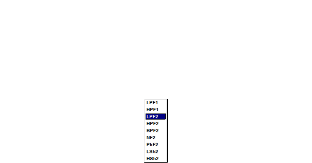
Yoshimi Software Synthesizer 6.2 Filter Settings
See Section 6.5.6.1 ”Formant Parameters” on page 96for the format parameters, which may have
slightly different names from what Paul used.
Astate variable (”StVarF”) filter is a type of active filter. The frequency of operation and the Q
factor can be varied independently. This and the ability to switch between different filter responses make
the state-variable filter widely used in analogue synthesizers.
Values: Analog*, Formant, StVarF
2. Filter Type. Selects the type of filter to be used, such as high-pass, low-pass, and band-pass. See
the dropdown element in Figure 54 ”Filter Type Dropdown” on page 79.
Figure 54: Type of Filter Passband, Dropdown Box
Values: LPF1, HPF1, LPF2*, HPF2, BPF2, NF2, PkF2, LSh2, HSh2
3. C.freq. Cutoff frequency or center frequency. This items has various definitions in the literature.
Usually it refers to the frequency at which the level drops to 3 Db below the maximum level. In various
dialogs, this value is the center frequency of the filter or the base position in a vowel’s sequence.
Values: 0 to 127, 90*
4. Q. The level of resonance for the filter. It indicates a measure of the sharpness of a filter. The higher
the Q, the sharper the filter. Generally, a higher Q value leads to a louder, more tonal affect for the filter.
Note that some filter types might ignore this parameter.
5. V.SnsA. Velocity sensing amount for filter cutoff. Velocity sensing amount of the filter.
Values: 0 to 127, 64*
6. V.Sns. Velocity sensing function of the filter. Set the amplitude of the velocity sensing.
Values: 0 to 127, 64*
7. freq.tr. Filter Frequency Tracking Amount. When this parameter is positive, higher note frequencies
shift the filter’s cutoff frequency higher. For the filter frequency tracking knob, left is negative, middle is
zero, and right is positive.
Values: 0 to 127, 64*
8. gain. Filter gain. Additional gain/attenuation for a filter. Also described as the filter output
gain/damping factor.
Values: 0 to 127, 64*
9. St. Filter stages. The more filter stages applied to a signal, the stronger (in general) the filtering. It
is the number of additional times the filter will be applied (in order to create a very steep roll-off, such
as 48 dB/octave). This dropdown element is shown in Figure 55 ”Filter Stage Dropdown” on page 80.
79
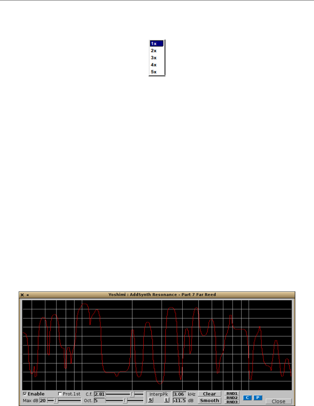
Yoshimi Software Synthesizer 6.3 Stock Resonance Settings
Obviously, the more stages used, the more calculation-intensive the filter will be. This should also increase
the latency (lag) of the filter.
Figure 55: Filter Stage Dropdown
10. 0/+. Filter tracking upgrade. Filter tracking could never quite reach 100%, so if using it to get
”notes” from noise it would go slightly out-of-tune. Yoshimi now has this new check box that changes its
range so that instead of -100% : 98.4% it will track 0% : 198.4%.
This new feature is one of the first that actually change instrument files. However, the format is
backwards compatible; older versions of Yoshimi simply ignore them.
Also present in this sub-panel are the usual Copy and Paste buttons that call up a copy-parameters
or a paste-parameters dialog.
6.3 Stock Resonance Settings
Yoshimi provides for setting very arbitrary ”resonance” settings for some sounds. In fact, ”resonance” is
too limiting a word. A lot of control over the spectrum is possible. The following dialog is used by the
ADDsynth editor, Figure 10.7 ”ADDsynth / Resonance” on page 160, and the the PADsynth editor,
The resonance editor is brought on-screen via the Resonance button of the ADDsynth or PADsynth
global part editors.
The resonance effect acts as a ”resonance box” or a filter with arbitrary frequency response. This
produces very realistic sounds. The cursor location is shown below the graph (the frequency, kHz, and
the amplitude, dB).
Paul Nasca has a video on YouTube that includes a demonstration of how the resonance dialog works
and affects the sound, if one cares to look for it.
Figure 56: ADDsynth/PADsynth Resonance
80

Yoshimi Software Synthesizer 6.3 Stock Resonance Settings
1. Graph Window
2. Enable
3. Max dB
4. C.f.
5. Oct.
6. Prot.1st
7. InterpPk
8. KHz
9. dB
10. Zero
11. Smooth
12. RND1
13. RND2
14. RND3
15. C
16. P
17. Close
1. Graph Window. Resonance Graph Window. Lets one draw the resonance frequency response in
”freehand” mode.
2. Enable. Resonance Enable. Turn the Resonance effect on.
Values: Off*, On
3. Max dB (wheel). The Maximum Amplitude (dB) wheel. Sets the amount of resonance: lower
values have little effect. Use the roller below to set it.
Values: 1 to 90, 20*
4. C.f. (knob). Center Frequency (kHz). Sets the center frequency of the graph. The value is shown
in the read-only text-box to the left.
Values: 0 to 127, 64* for 0.10 to 10.0, 1.0*
5. Oct. Number of Octaves. Sets the number of octaves the graph represents. The value is shown in
the read-only text-box to the left.
Values: 0 to 127, 64* for 0 to 10, 5*
6. Prot.1st. Protect the fundamental Frequency. That is, do not damp the first harmonic.
Values: Off, On
7. InterpPk. Interpolate the resonance peaks. This setting used to be a weird one where the mouse
button (left versus right) affected the kind of interpolation used, but also affects the next field as well,
but in Yoshimi 1.3.9 the mechanism for interpolation has been made more clear. In addition, some of the
controls have been changed to sliders for easier usage.
This setting allows one to make resonance functions very easily. To use it effectively, first, clear the
graph using the Clear button. Click the left button on a position on the graph to create a peak (or do
it more than once to create more peaks). Click either the InterpPk S button (smooth interpolation) or
the InterpPk L button (linear interpolation). Yoshimi will interpolate automatically between the peaks
drawn, as shown in Figure 57 ”ADDsynth/PADsynth Resonance Interpolated” on page 82, which shows
smooth interpolation.
81
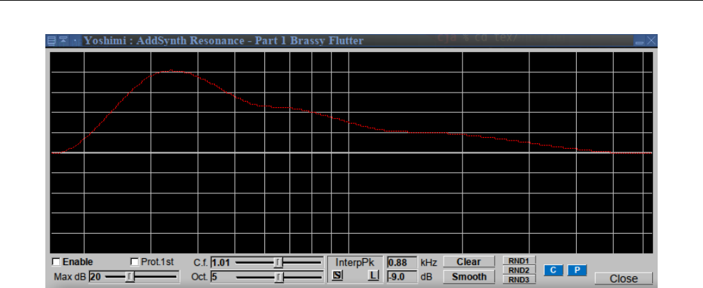
Yoshimi Software Synthesizer 6.3 Stock Resonance Settings
Figure 57: ADDsynth/PADsynth Resonance Interpolated
Please do not confuse this ”smoothing” with the processing done using the Smooth button discussed
below.
Also note that one can clear a part of the graph by dragging with the right mouse button. In fact, the
interpPk functionality interpolates between non-zero values. Oh, and note that the kHz and dB fields
update to match it. And don’t forget to try the middle-click feature to see the corresponding command-line
needed to achieve the setting.
8. KHz. The current frequency on graph.
9. dB. The current level on graph window.
Values: -90 to +90
10. Clear. Clear the resonance function. (Used to be called ”Zero”.) Clear the graph.
11. Smooth. Smooth the resonance function. Smooth the graph. This button causes each jagged portion
of the graph to be smoothed. This smooth does not interpolate between the peaks, unlike the InterpPk
functionality described earlier. Compare the interpolation shown in Figure 57 ”ADDsynth/PADsynth
Resonance Interpolated” on page 82, and the smoothing shown in Figure 58 ”ADDsynth/PADsynth
Resonance Smoothed” on page 83.
82
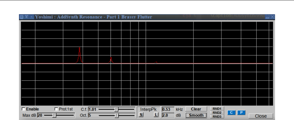
Yoshimi Software Synthesizer 6.4 LFO Settings
Figure 58: ADDsynth/PADsynth Resonance Smoothed
Note how the amplitude of the peaks is also reduced by the smoothing. Presumably, a frequency-
smoothing window is applied to the peaks, thus making each new data-point a weighted average of the
data-points around it. Don’t forget to try the middle-click feature to see the corresponding command-line
needed to achieve the setting.
12. RND1. Randomize the resonance function, 1. RND1, RND2, RND3 are used to create random
resonance functions.
13. RND2. Randomize the resonance function, 2.
14. RND3. Randomize the resonance function, 3.
15. C. Copy Dialog.
16. P. Paste Dialog.
17. Close. Close.
6.4 LFO Settings
Yoshimi provides LFOs for it amplitude, frequency, and filtering functions. ”LFO” means Low Frequency
Oscillator. These oscillators are not used to make sounds by themselves, but they change parameters
cyclically as a sound plays.
LFOs are, as the name says, oscillators with, compared to the frequency of the sound, low frequency.
They often appear in order to control the effect.
83
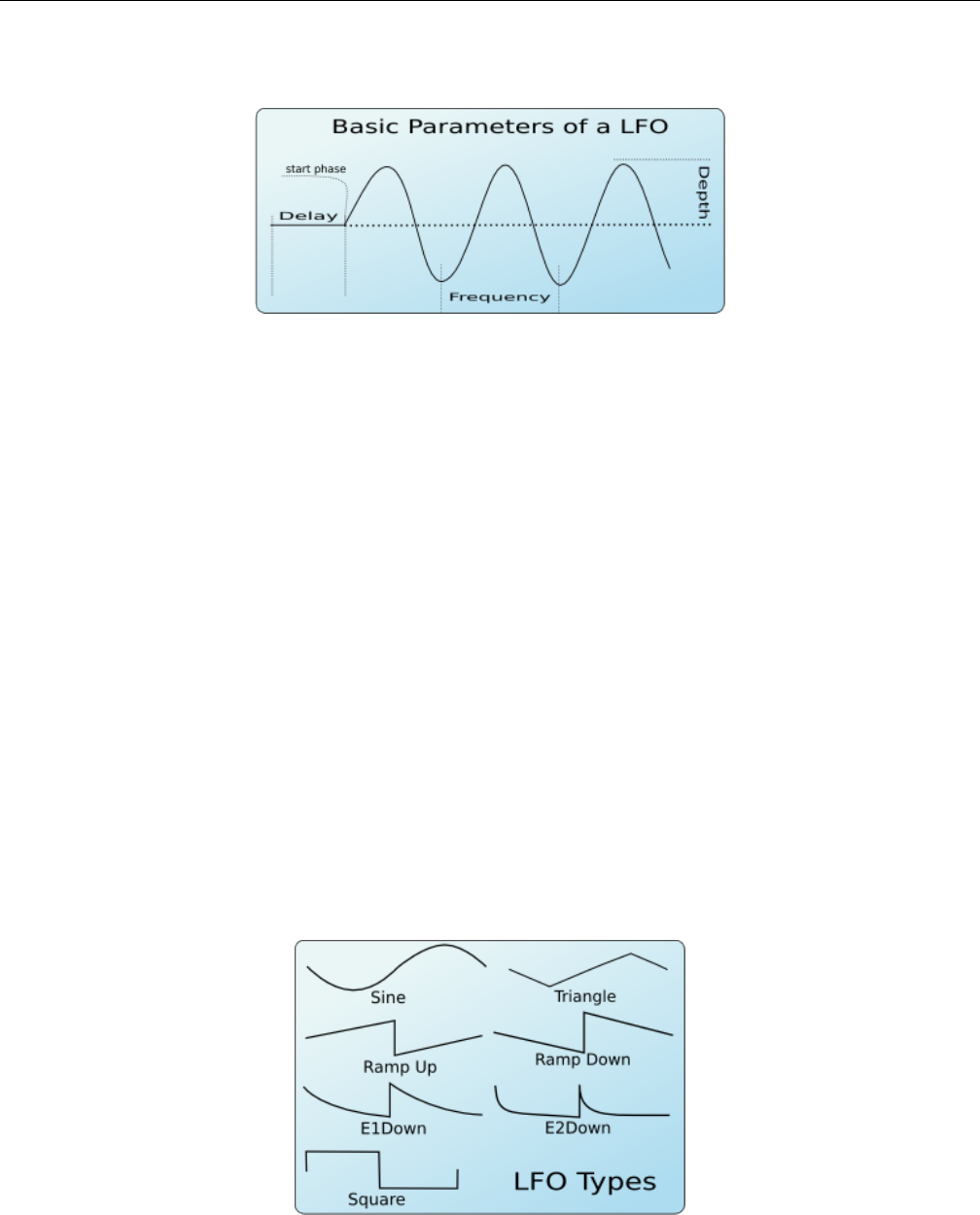
Yoshimi Software Synthesizer 6.4 LFO Settings
6.4.1 LFO Basic Parameters
Figure 59: Basic LFO Parameters
1. Delay.
2. Start Phase.
3. Frequency.
4. Depth.
The LFOs has some basic parameters (see Figure 59 ”Basic LFO Parameters” on page 84.
1. Delay. LFO Delay. This parameter sets how much time takes since the start of the note to start the
cycling of the LFO. When the LFO starts, it has a certain position called ”start phase”.
2. Start Phase. LFO Start Phase. The angular position at which a LFO waveform will start.
3. Frequency. LFO Frequency. How fast the LFO is (i.e. how fast the parameter controlled by the
LFO changes.)
4. Depth. LFO Depth. The amplitude of the LFO (i.e. how much the parameter is controlled by the
LFO changes.)
6.4.2 LFO Function
Another important additional LFO parameter is the shape or type of the LFO. There are many LFO
Types that vary according to the function used to generate the LFO. Yoshimi supports the LFO shapes
shown in Figure 60 ”LFO Functions” on page 84.
Figure 60: LFO Types, Shapes, or Functions
84
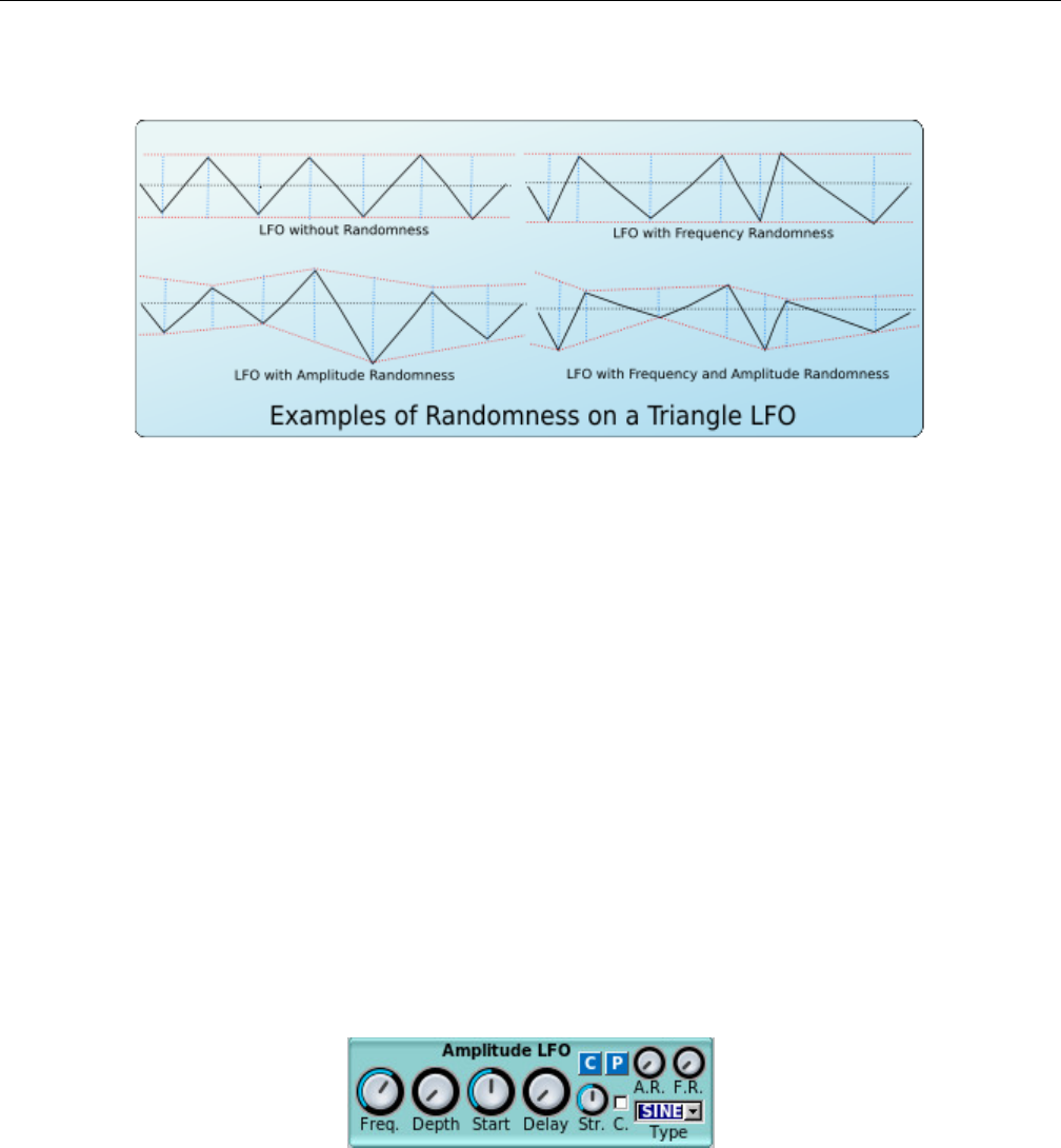
Yoshimi Software Synthesizer 6.4 LFO Settings
6.4.3 LFO Randomness
Figure 61: LFO Randomization
Another parameter is the LFO Randomness. It modifies the LFO amplitude or the LFO frequency at
random. In Yoshimi one can choose how much the LFO frequency or LFO amplitude changes by this
parameter. Observe Figure 61 ”LFO Randomization” on page 85. It shows some examples of randomness
and how it changes the shape of a triangle LFO.
6.4.4 LFO, More Settings
Other settings are available as well.
Continous mode: If this mode is used, the LFO will not start from ”zero” on each new note, but it
will be continuous. This is very useful if one applies on filters to make interesting sweeps.
Stretch: It controls how much the LFO frequency changes according to the note’s frequency. It can
vary from negative stretch (the LFO frequency is decreased on higher notes) to zero (the LFO frequency
will be the same on all notes) to positive stretch (the LFO frequency will be increased on higher notes).
6.4.5 LFO User Interface Panels
Figure 62: Amplitude LFO Sub-Panel
In Yoshimi, LFO parameters are available for amplitude, filters, and frequency. They all have essentially
the same interface elements. Note Figure 62 ”Amplitude LFO Sub-Panel” on page 85, which shows an
example of an LFO stock sub-panel.
These parameters are:
1. Freq
2. Depth
85

Yoshimi Software Synthesizer 6.4 LFO Settings
3. Start
4. Delay
5. A.R
6. F.R
7. Cor C.
8. Str
9. Type
10. C(copy)
11. P(paste)
1. Freq. LFO Frequency. This parameter varies from 0 to 1. We still need to figure out what that scale
means, however. Obviously, it is a relative scale, and is perhaps related to the overall sampling frequency.
Values: 0 to 1, 0.63*
2. Depth. LFO Depth. Also called ”LFO Amount”.
Values: 0* to 127
3. Start. LFO Start Phase. If this knob is at the lowest value, the LFO Start Phase will be random.
Values: 0 = random, to 127, 64*
4. Delay. LFO Delay.
Values: 0* to 127
5. A.R. LFO Amplitude Randomness.
Values: 0* to 127
6. F.R. LFO Frequency Randomness.
Values: 0* to 127
7. C. LFO Continous Mode.
Values: Off*, On
8. Str. LFO Stretch. See the image in Figure 62 ”Amplitude LFO Sub-Panel” on page 85. It shows
that the LFO stretch is set to zero, though the tooltip would show it to be 64.
Values: 0 to 127, 64*
9. Type. LFO Function. Also present in this sub-panel are the usual Copy and Paste buttons that
call up a copy-parameters or paste-parameters dialog.
Values: SINE*, TRI, SQR, R.up, R.dn, E1dn, E2dn
Figure 63: LFO Function Type Drop-down
10. Type. LFO Type (or Shape, or Function). The various shapes of LFO functions are shown in
Figure 60 ”LFO Functions” on page 84. The values that can be selected are shown in Figure 63 ”LFO
86
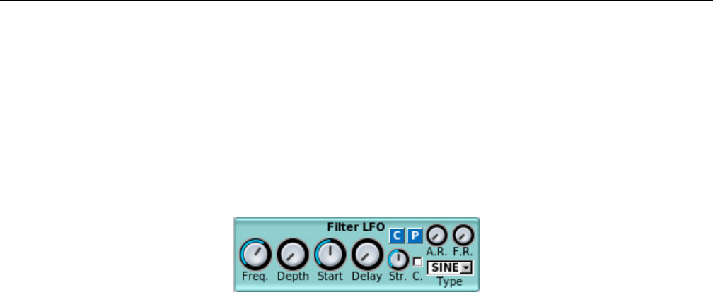
Yoshimi Software Synthesizer 6.4 LFO Settings
Type Drop-down” on page 86. Also present in this sub-panel are the usual Copy and Paste buttons that
call up a copy-parameters or paste-parameters dialog.
Values: SINE*, TRI, SQR, R.up, R.dn, E1dn, E2dn
For reference, Figure 64 ”Filter LFO Sub-Panel” on page 87shows the LFO sub-panel for a filter,
and Figure 66 ”Frequency LFO Sub-Panel” on page 88shows the LFO sub-panel for frequency.
6.4.6 Filter LFO Sub-panel
Figure 64: Filter LFO Sub-Panel
1. Enable (present on some versions of this sub-panel).
2. Freq.
3. Depth
4. Start
5. Delay
6. Str.
7. C.
8. A.R.
9. F.R.
10. Type
11. C
12. P
1. Enable. Enable the panel. (Present on some versions of this sub-panel).
2. Freq. LFO Frequency.
Values: 0 to 1, 0.64*
3. Depth. LFO Amount.
Values: 0* to 127
4. Start. LFO Startphase (leftmost is random).
Values: 0 to 127, 64*
5. Delay. LFO Delay.
Values: 0* to 127
6. Str. LFO Stretch.
Values: 0 to 127, 64*
7. C. Continuous LFO.
Values: Off*, On
8. A.R. LFO Amplitude Randomness.
Values: 0* to 127
87
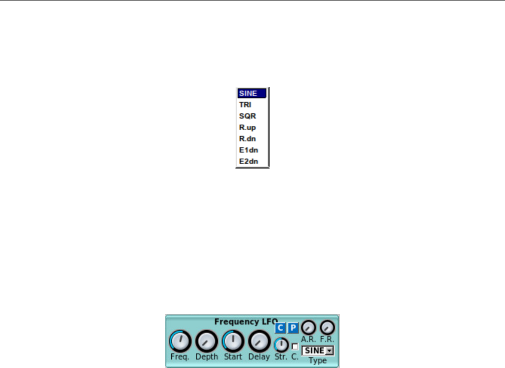
Yoshimi Software Synthesizer 6.5 Envelope Settings
9. F.R. LFO Frequency Randomness.
Values: 0* to 127
10. Type. LFO Type.
Figure 65: LFO Function Type Dropdown
Values: SINE*, TRI, SQR, R.up, R.dn, E1dn, E2dn
11. C. Copy to Clipboard/Preset.
12. P. Paste from Clipboard/Preset.
6.4.7 Frequency LFO Sub-panel
Figure 66: Frequency LFO Sub-Panel
This panel is basically identical to the Filter LFO panel described in the previous section.
6.5 Envelope Settings
Envelopes control how the amplitude, the frequency, or the filter changes over time. The general envelope
generator has four sections:
1. Attack. The attack is the initial envelope response. It begins when the key for the note is first held
down (at Note On). The volume starts at 0, and rises fast or slowly until a peak value. In Yoshimi,
the attack is always linear.
2. Decay When the attack is at its highest value, it immediately begins to decay to the sustain value.
The decay can be fast or slow. The attack and decay together can be used to produce something
like horn blips, for example.
3. Sustain This is the level at which the parameter stays while the key is held down, i.e. until a Note
Off occurs.
4. Release When the key is released, the sound decays, either fast or slowly, until it is off (the volume
is 0).
Together, these values are called ”ADSR”. The ADSR envelope generally controls the amplitude of
the sound. In Yoshimi, amplitude envelopes can be linear or logarithmic.
88
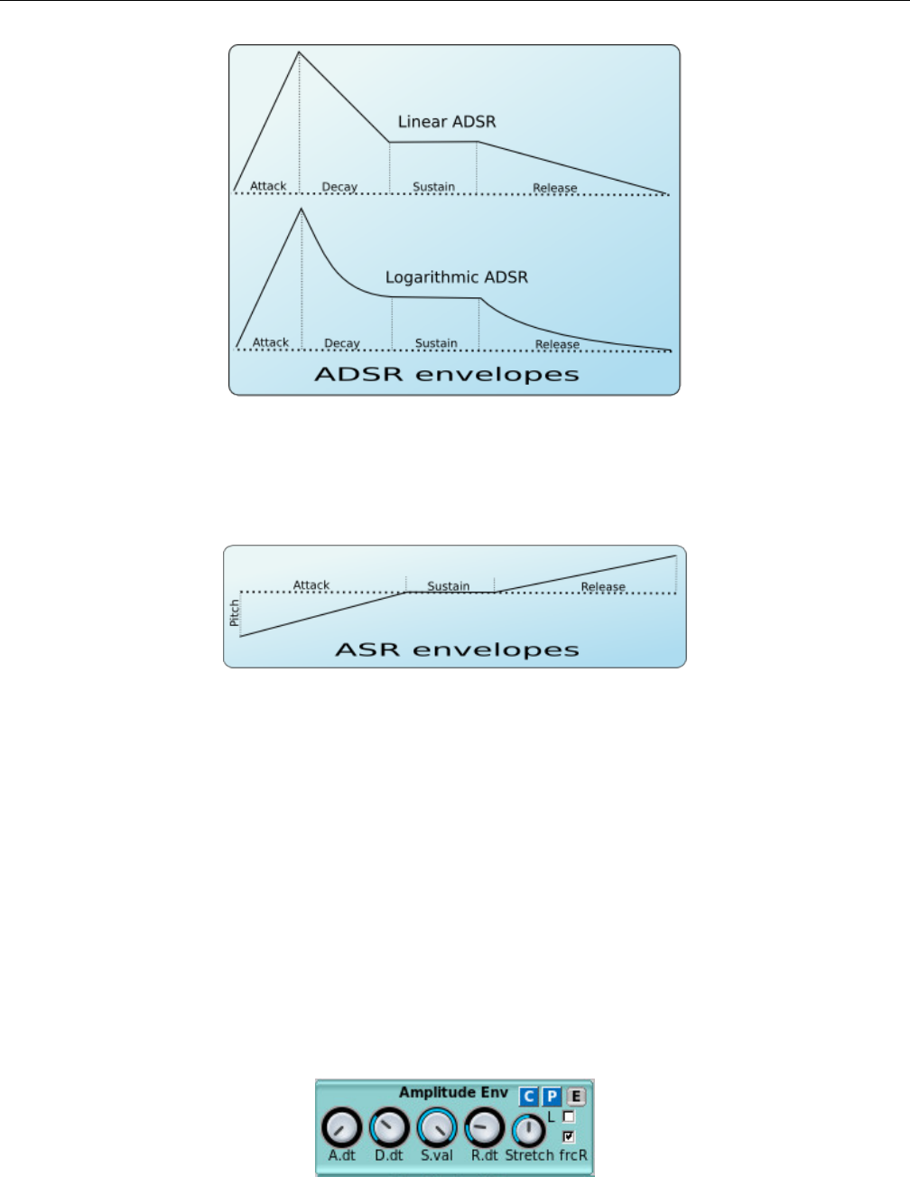
Yoshimi Software Synthesizer 6.5 Envelope Settings
Figure 67: ADSR Envelope (Amplitude)
See Figure 67 ”ADSR Envelope (Amplitude)” on page 89, it shows a depiction of an ADSR envelope.
The ADSR is mostly applied to amplitude envelopes.
Figure 68: ASR Envelope, Frequency
Frequency envelopes control the frequency (more exactly, the pitch) of the oscillators. The following
image depicts the stages of these envelopes.
For frequency envelopes, a simpler form of envelope is used. This envelope is an ASR envelope, shown
in Figure 68 ”ASR Envelope, Frequency” on page 89. The dotted line represents the real pitch of the
sound without the envelope. The frequency envelopes are divided into 3 stages:
1. Attack. It begins at the Note On. The frequency starts from a certain value and glides to the real
frequency of the note.
2. Sustain. The frequency stays the same during the sustain period.
3. Release. This stage begins on Note Off and glides the frequency of the note to a certain value.
6.5.1 Amplitude Envelope Sub-Panel
Figure 69: Amplitude Envelope Sub-Panel
89

Yoshimi Software Synthesizer 6.5 Envelope Settings
1. A.dt
2. D.dt
3. S.val
4. R.dt
5. Str
6. L
7. frcR
8. C
9. P
10. E
1. A.dt. Attack duration, attack time. We need to determine the units of time at play for ADSR
durations.
Values: 0* to 127
2. D.dt. Decay duration, decay time.
Values: 0 to 127, 44*
3. S.val. Sustain value. This is the (relative?) level at which the envelope will settle while the note is
held down. The only stage that always remains defined is the Sustain, where the envelopes freezes until
a Note Off event.
Values: 0 to 127*
4. R.dt. Release time.
Values: 0 to 127, 25*
5. Str. Stretch. How the envelope is stretched according the note. Envelope Stretch means that, on
lower notes, the envelope will be longer. On the higher notes the envelopes are shorter than lower notes. In
the leftmost value, the stretch is zero. The rightmost use a stretch of 200%; this means that the envelope
is stretched about 4 times per octave.
Values: 0 to 127, 64*
6. L. Linear envelope. If this option is set, the envelope is linear, otherwise, it will be logarithmic.
Values: Off*, On
7. frcR. Forced release. This means that if this option is turned on, the release will go to the final
value, even if the sustain stage is not reached. Usually, this must be set. If this option is turned on, the
release will go to the final value, even if the sustain level is not reached. Also present in this sub-panel
are the usual Copy and Paste buttons that call up a copy-parameters or paste-parameters dialog.
Values: Off, On*
8. C. Copy to Clipboard/Preset.
9. P. Paste from Clipboard/Preset.
10. E. Amplitude Envelope Editing Window. Described in the next section.
6.5.2 Envelope Settings
This section describes the Amplitude Envelope Editing window.
90
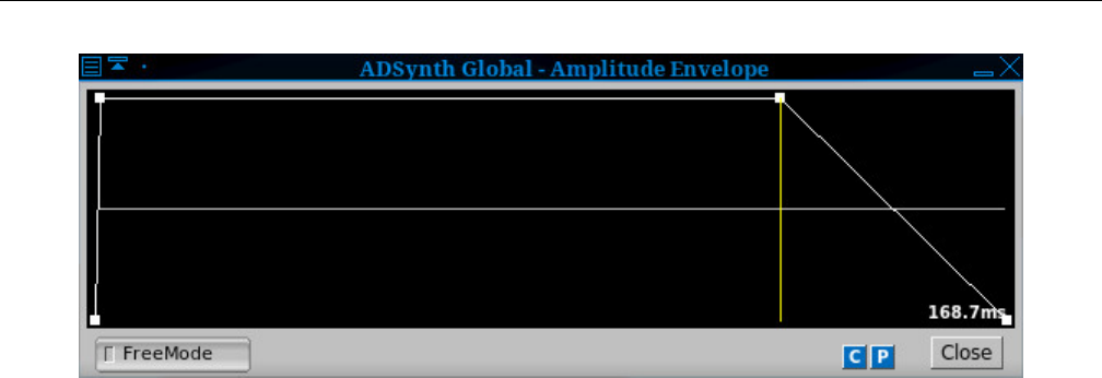
Yoshimi Software Synthesizer 6.5 Envelope Settings
Figure 70: Amplitude/Filter/Frequency Envelope Editor
1. Graph Window
2. FreeMode
3. C
4. P
5. Close
1. FreeMode. Freemode Enable. Enables the envelope editor’s Free Mode. See the next section for
details.
Values: Off*, On
6.5.3 Freemode Envelope Settings
The envelope panels are parts that control a parameter (such as the frequencies) of a sound. For all
envelopes, there is a mode that allows the user to set an arbitrary number of stages and control points.
This mode is called Freemode. The only stage that always remains defined is the Sustain, where the
envelopes freezes until a Note Off event. The Freemode envelope editor has a separate window to set the
parameters and controls.
The main concept of the freemode editor window is the control point. One can move the points using
the mouse. In the right on the window, it shows the total duration of the envelope. If the mouse button
is pressed on a control point, it will be shown the duration of the stage where the point is.
Figure 71 ”Amplitude/Filter/Frequency Envelope Freemode Editor” on page 92shows an example of
the stock Freemode envelope editor, with Freemode enabled.
91
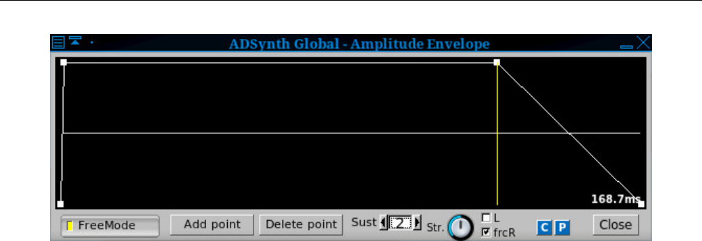
Yoshimi Software Synthesizer 6.5 Envelope Settings
Figure 71: Amplitude/Filter/Frequency Envelope Freemode Editor
All of the envelope editors have some common controls.
1. Graph Window
2. Add point
3. E
4. FreeMode
5. Add point
6. Delete point
7. Sust
8. Stretch
9. L
10. frcR
11. Close
12. C
13. P
1. E. Editor. Graph Window. Shows a window with the real envelope shape and the option to convert
to Freemode to edit it. The envelope editor shows a window in which one can view and modify the
detailed envelope shape, or convert it to Freemode to edit it almost without restriction. By default, only
the Freemode button/checkbox is visible.
If an envelope has FreeMode enabled, it allows one to edit the graph of the envelope directly. Select
a point from the graph and move it. Notice that only the line before the currently edited point of the
envelope changes its duration. As the point is dragged, the text on the right shows the duration of the
line before it. Otherwise, the text shows the total duration of the envelope.
If the envelope doesn’t have the FreeMode mode enabled, it doesn’t allow one to move the points;
the envelope window is then useful only to see what happens if one changes the ADSR settings.
2. FreeMode. FreeMode. Provides a mode where completely arbitrary envelopes may be drawn.
Actually, the envelopes aren’t completely arbitrary, as the sustain section is always flat, and its duration
corresponds with the duration the note is held down. When this mode is enabled, the rest of the controls
shown in Figure 71 ”Amplitude/Filter/Frequency Envelope Freemode Editor” on page 92appear, and
are described in the following paragraphs.
Values: Off*, On
3. Add point. Add point. Provides a way to add a data point to the Freemode envelope. It adds the
point after the currently-selected point. One can select a point by clicking on it.
92

Yoshimi Software Synthesizer 6.5 Envelope Settings
4. Delete point. Delete point. Provides a way to delete the current data point from the Freemode
envelope.
5. Sust. Sustain point. Sets the sustain point. The sustain point is shown using the yellow line. If the
point is at 0, then sustain is disabled. It is difficult to determine the difference between 1 and 2.
1. 0 means that sustain is disabled, and the envelope immediately starts dying, even if the note is held.
2. 1 seems to mean the sustain curve follows its course while the note is held.
3. 2 seems to mean that extra sustain kicks in after the note is released.
Values: 0, 1, 2*
6. Stretch. Envelope Stretch. How the envelope is stretched according the note. On the higher notes
the envelopes are shorter than lower notes. At the leftmost value, the stretch is zero. The rightmost sets
a stretch of 200%; this means that the envelope is stretched about four times/octave.
7. L. Envelope Linear. This setting is only available in the amplitude envelope. If enabled, the envelope
is linear. If not enabled, the envelope is logarithmic (dB).
Values: Off*, On
8. frcR. Forced Release. This means that if this option is turned on, the release will go immediately
to the final value, even if the sustain stage is not reached. Usually, this must be set. When the key is
released, the position of the envelope jumps directly to the point after the release point. If the release is
disabled, the envelope position jumps to the last point on release.
Values: Off*, On
9. Close. Close Dialog.
Also present in this sub-panel are the usual Copy and Paste buttons that call up a copy-parameters
or paste-parameters dialog, as well as a button to bring up the editor window.
6.5.4 Envelope Settings, Frequency
These envelopes controls the frequency (more exactly, the pitch) of the oscillators. Observe Figure 68
”ASR Envelope, Frequency” on page 89. It depicts the stages of these envelopes. The dotted line represents
the real pitch of the sound without the envelope.
The frequency envelopes are divided into 3 stages: attack (see 1.); sustain (see 3.); and release (see
4.).
One question to answer is: can the attack and release go in the opposite directions, or do the knob
ranges prohibit this?
Figure 72: Frequency Envelope Sub-Panel
1. Enable (present on some versions of this sub-panel).
2. A.value or A.val
3. A.dt
4. R.dt
93

Yoshimi Software Synthesizer 6.5 Envelope Settings
5. R.val (present on some versions of this sub-panel).
6. Stretch
7. frcR
8. C
9. P
10. E
For Frequency Envelopes the interface has the following parameters:
1. Enable. Enable the panel. (Present on some versions of this sub-panel).
2. A.val. Attack value. We need to figure out what this means.
Values: 0 to 127, 64*
3. A.dt. Attack duration. Attack time.
Values: 0 to 127, 40*
4. R.dt. Release time.
Values: 0 to 127, 60*
5. R.val. Release Value. Actually present only on the Frequency Env sub-panel.
Values: 0 to 127, 64*
6. Stretch. Envelope Stretch. Envelope Stretch (on lower notes make the envelope longer).
Values: 0 to 127, 64*
7. frcR. Forced release. If this option is turned on, the release will go to the final value, even if the
sustain level is not reached.
Values: Off, On*
Also present in this sub-panel are the usual Copy and Paste buttons that call up a copy-parameters
or paste-parameters dialog, as well as a button to bring up the editor window.
6.5.5 Envelope Settings for Filter
This envelope controls the cutoff frequency of the filters. The filter envelopes are divided into 4 stages:
1. Attack. It begins at the Note On. The cutoff frequency starts from a certain value and glides to
another value.
2. Decay. The cutoff frequency continues to glide to the real cutoff frequency value of the filter (dotted
line).
3. Sustain. The cutoff frequency stays the same during the sustain period (dotted line).
4. Release. This stage begins on Note Off and glides the filter cutoff frequency of the note to a certain
value.
Figure 73: Filter Envelope Sub-Panel
94

Yoshimi Software Synthesizer 6.5 Envelope Settings
The newest version of this panel spells out ”Filter Envelope”. Not worth a new screen-shot. The
items in this panel are:
1. A.value
2. A.dt
3. D.val
4. D.dt
5. R.dt
6. Stretch
7. frcR
8. L
Filter Envelopes has the following parameters:
1. A.value. Attack Value. Starting Value. We need to figure out what this means.
Values: 0 to 127, 64*
2. A.dt. Attack Duration. Attack Time.
Values: 0 to 127, 40*
3. D.val. Decay Value.
Values: 0 to 127, 64*
4. D.dt. Decay Duration. Decay Time.
Values: 0 to 127, 70*
5. R.dt. Release time.
Values: 0 to 127, 60*
6. Stretch. Stretch. Envelope Stretch (on lower notes make the envelope longer).
Values: 0 to 127, 64*
7. frcR. Forced Release. If this option is turned on, the release will go to the final value, even if the
sustain level is not reached.
Values: Off, On*
Also present in this sub-panel are the usual Copy and Paste buttons that call up a copy-parameters
or paste-parameters dialog, as well as a button that bring up the editor window.
8. L. If this option is set, the envelope is linear, otherwise, it will be logarithmic.
Values: Off*, On
6.5.6 Formant Filter Settings
This window allows one to change most of the parameters of the formant filter. It is reached by enabling a
FILTER panel in an AddSynth part, changing the Category (top right in the Filter Params sub-panel)
value to Formant, and then clicking the Edit button that sits below the category drop-down list.
95
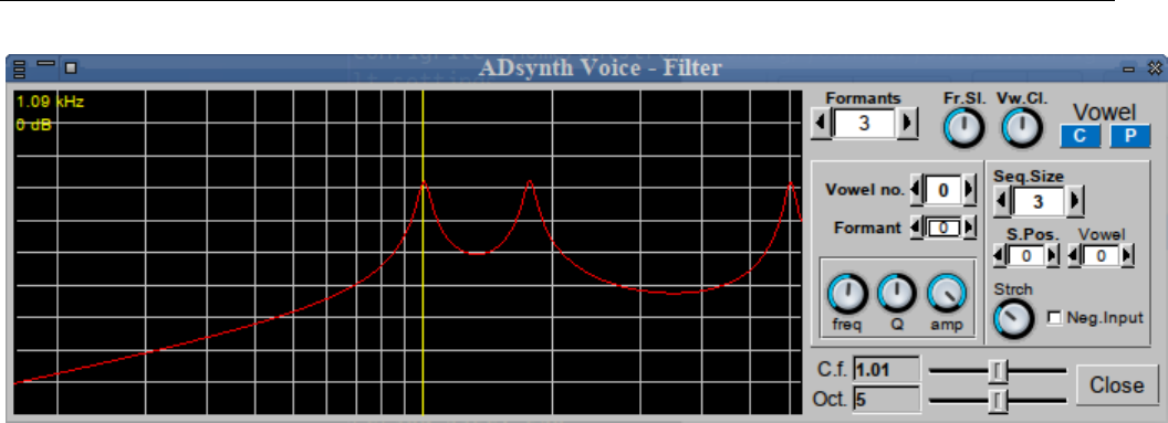
Yoshimi Software Synthesizer 6.5 Envelope Settings
Figure 74: Formant Filter Editor Dialog
This editor dialog provides a lot of functionality:
1. Graph Window
2. Formants
3. Fr.Sl.
4. Vw.Cl.
5. C.f.
6. Oct.
7. Vowel no.
8. Formant
9. freq
10. Q
11. amp
12. Seq.Size
13. S.Pos.
14. Vowel
15. Strtch
16. Neg Input
6.5.6.1 Formant Parameters
9. Formants Graph Window. The graph window shows the formant frequency envelope in red, and
one or more vertical yellow lines at each formant’s center frequency. As the mouse pointer is moved over
the graph, other format center frequencies may appear, highlighted in yellow. Various mouse actions will
modify the formant graph in a manner that might be more intuitive than frobbing the spin and knob
controls.
One can control some of the parameters by placing the mouse pointer over the yellow lines representing
each formant. Hold down the left or right mouse button and move the mouse sideways: this action will
change the formant’s center frequency. The Left button down: moving vertically will change the amplitude.
The Right button down: moving vertically changes the formant’s Q factor. Anywhere on the graph: the
scroll-wheel changes the octave range, and holding Shift at the same time changes the center frequency.
Thus, one can control most of the formant features one-handed, quickly, while also playing on a
keyboard. If one’s mouse has extra buttons on the sides (mine hasn’t) you can also use these to switch
96

Yoshimi Software Synthesizer 6.5 Envelope Settings
between the formats instead of moving the mouse across to the next one. While making changes, one sees
the respective knobs/sliders moving too; these are still fully functional.
An important detail is the, uniquely, there is no ’default’ value for formant frequency. This value will
be set randomly, but, once saved, will be fixed like all the other controls.
10. Formants. Number of Formants Used.
Values: 1 to 12, 3*
11. Fr.Sl. Formant Slowness. This parameters prevents too-fast morphing between vowels.
Values: 0 to 127, 64*
12. Vw.Cl. Vowel ”Clearness”. Sets how much the vowels are kept ”clear”, that is, how much ”mixed”
vowels are avoided.
Values: 0 to 127, 64*
13. C.f. Center Frequency. This slider control changes the center frequency of the graph, in relative
units. Not quite sure how to describe this one, so play with the slider and see (and hear) for oneself.
Values: 0.09 to 10.00, 1.0*
14. Oct. Number of Octaves. This slider controls the number of octaves shown in the graph.
Values: 0 to 10
6.5.6.2 Formant Vowel Parameters
15. Vowel no. Vowel Number. The number of the current vowel. Each number represents a different
vowel, and leads to a gross change in the shape of the formant spectrum. We do not yet have a mapping
between the numbers and which vowel is represented.
Values: 0 to 5
16. Formant. Formant Number. The current formant to be emphasized or modified. The vertical
marker in the graph moves as this value is changed.
Values: 0 to 11
17. freq. Formant Frequency. The frequency of the current formant. This knob changes the frequency
of the formant peak selected by the Formant Number control.
Values: 0 to 127
18. Q. Formant Resonance, Formant Q. The Q (resonance depth or bandwidth) of the current formant.
Used to sharpen or make the current formant sound dull.
Values: 0 to 127
19. amp. Formant Amplitude. Controls the amplitude of the current formant. Initially, one will want
to set this to the maximum value.
Values: 0 to 127
6.5.6.3 Formant Sequence Parameters
The sequence represents what vowel is selected to sound according to the input from the filter envelopes
and LFO’s. We need to learn a bit about how this setup actually works.
20. Seq Size. Sequence Size. The number of vowels in the sequence.
97

Yoshimi Software Synthesizer 6.6 Clipboard Presets
Values: 1 to 7
21. S.Pos. Sequence Position. The current position of the sequence.
Values: 0 to 6
22. Vowel. Vowel Position. The vowel from the current position.
Values: 0 to 5
23. Strtch. How the sequence is stretched. This number probably means that the duration of the
sequence decreases as the pitch of the selected notes increase.
Values: 0 to 127
24. Neg Input. Negative Input. If enabled, the input from the envelope or LFO control is reversed.
Values: off, on
6.6 Clipboard Presets
In many of the settings panels, there are buttons labelled C,P, and E.Eis the editor window, discussed
in section 6.5.3 Cand Pare the clipboard/preset copy and paste dialogs, respectively. These buttons
allow cut-and-paste for shorter sections of the XML configuration.
The preset dialog also provides a way to save a preset to a preset file. The naming convention for
a preset file is presetname.presettype.xpz, where presename is the name one types into the Copy to
Preset name field, presettype is the name that appears in the Type field, and xpz is the file-extension
for compressed XML preset files.
The presets are stored in the current default preset directory, which is normally ~/.config/yoshimi/presets.
Preset directories can be added to the list, and the default preset directory can be changed. See Section 4.4
”Menu / Paths” on page 62.
6.6.1 Clipboard/Preset Copy
Note that Figure 75 ”Copy to Clipboard” on page 99shows an example of the copying dialog for the
clipboard.
98
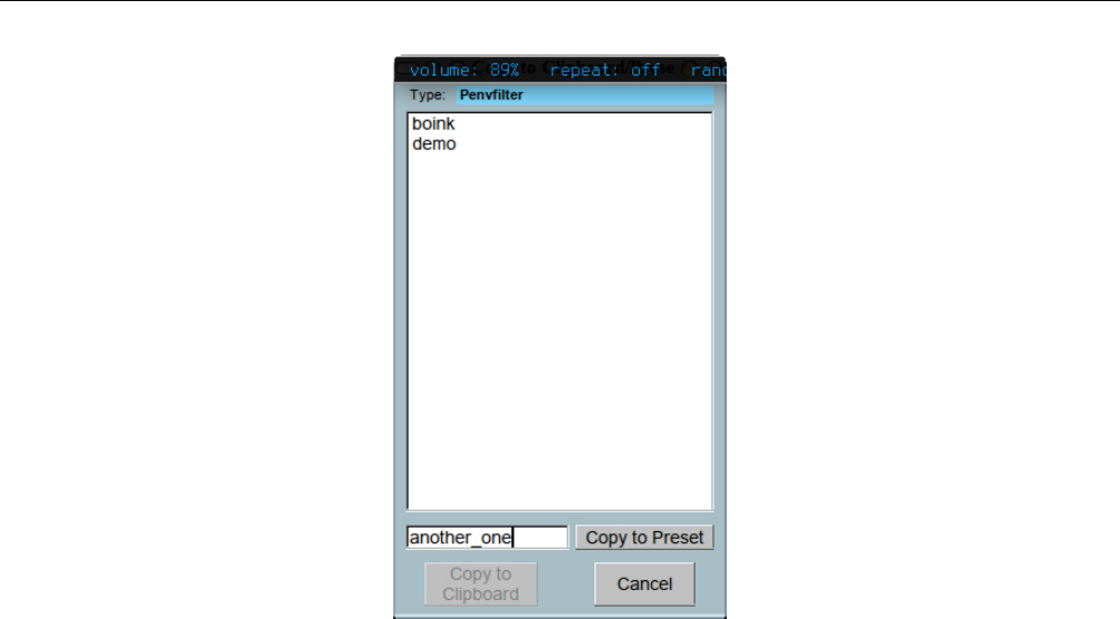
Yoshimi Software Synthesizer 6.6 Clipboard Presets
Figure 75: Copy to Clipboard/Presets
1. Type. Clipboard type for copying. This field indicates the context (e.g h. ”envamplitude”) or name
of the clipboard to which the data will be copied. If the preset is saved/copied to a file, this field becomes
the second part of the preset’s file-name.
2. Clipboard list. Clipboard list. This itemm is actually a list of preset files available to be selected
for this block of Yoshimi settings.
3. Copy to Preset. Clipboard to preset. Provides a way to specify the preset (and, indirectly, the
preset file) to which this data should be copied.
To save to a preset, type the desired name of the setting. This entry will enable this button. When
the button is pressed, the preset will be saved to the default preset directory. Be sure to set up a default
present directory where ordinary users have write permissions! A good choice for a preset directory is
~/.config/yoshimi/presets. The file-name of the of the preset will be a non-hidden file such as
my_preset.ADnoteParameters.xpz
The middle part of this name is shown near the top of the preset dialog, as a cue. There is no way
in Yoshimi to change this part of the file-name. And don’t do it using file system commands! Modify the
first part of the file-name to distinguish it from other versions of the preset. Only the type-name will ever
be visible in the Yoshimi presets Type field.
Note that Yoshimi ships with a number of non-hidden .xpz files.
4. Copy to Clipboard. Copies the preset to the clipboard.
6.6.2 Clipboard/Preset Paste
Observe Figure 76 ”Paste from Clipboard” on page 100. It shows an example of the pasting dialog for
the clipboard.
99
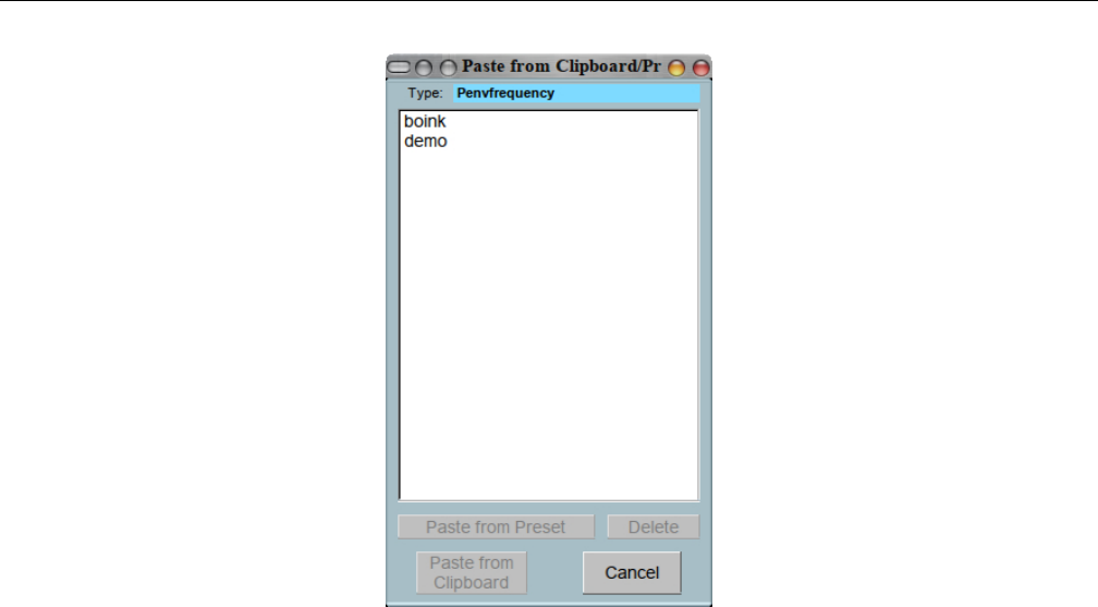
Yoshimi Software Synthesizer
Figure 76: Paste from Clipboard/Presets
1. Add point
2. Type
3. Clipboard list
4. Paste from Preset
5. Paste from Clipboard
1. Type. Clipboard type for pasting. This field indicates the context (e.g h. ”envamplitude”) or name
of the clipboard to which the data will be copied.
2. Clipboard list. Clipboard list.
3. Paste from Preset. Paste from preset. Provides a way to specify the preset to which this data
should be copied.
4. Paste from Clipboard. Clipboard to preset.
7 Top Panel
The Yoshimi top panel provides quick access to some major features of the application. The top panel is
shown in Figure 2”Yoshimi Main Screen” on page 21.
Here are the major elements of the top panel.
1. Stop!
2. Reset
3. Mixer Panel
4. Virtual Keybd
5. Vectors
6. Reports
100

Yoshimi Software Synthesizer 7.1 Mixer Panel Window
7. Key Shift
8. Detune
9. Volume
1. Stop!. Stop! This button causes Yoshimi to ”Cease all sound immediately!” Useful when MIDI input
suddenly stops due to a bug in the MIDI source.
2. Reset. Master Reset. Resets Yoshimi to its default state, when no default configuration files exist.
If there is a saved default state and the start with default option is set, then a reset will reload that
file. For any other situation it will set the first-time defaults.
If the Ctrl key is held down while doing a master reset, then MIDI Learn will also be cleared.
3. Mixer Panel. This button brings up a panel that shows a ”mixer” view of all of the parts that
have been created in the current state of Yoshimi.
For the details of this panel, see Section 7.1 ”Mixer Panel Window” on page 101.
4. Virtual Keybd. This button brings up the virtual keyboard, which is a way to enter MIDI
information without a real MIDI keyboard. It also provides a way to use the computer keyboard for faster
playing. See Section 7.2 ”Virtual Keyboard” on page 104.
5. Vectors. Provides the recent new feature of vector control. This has been moved moved to this
button from the Yoshimi menu. See Section 16.2 ”Vector Dialogs” on page 195.
6. Reports. This button is active only if reports are not going to stdout, by setting Yoshimi /
Settings / Main Settings / Send reports to: to Console Window (see Section 4.1.3.1 ”Menu /
Yoshimi / Settings / Main Settings” on page 34for this item.) When pressed, the Yoshimi console window
is opened.
7. Key Shift. Master Key Shift. This is the key-shift (transpose) that applies to all parts, in units
of semitones. In recent versions of Yoshimi, this range has been extended. Also note that the master key
shift can be set via the user-interface, the command-line, or (we suspect) by MIDI NRPN commands.
Values: -36 to 36, 0*
Also see the Key Shift item in Section 9”Bottom Panel” on page 133for more information.
8. Detune. Detune. Provides a global fine detune functionality. The fine detune mapping to the knob
values shown below is -64 to 63 cents.
Values: 0 to 127, 64* (float)
9. Volume. Volume, Master Volume. Controls the overall volume of all sounds generated by Yoshimi.
Values: 0 to 127, 90*
7.1 Mixer Panel Window
The Mixer Panel button opens the ”Mixer” window. The mixer provides a global view of the most
important adjustable parameters of all of the defined parts. There are two views, a 2x8 view and a 2x16
view. See Figure 77 ”Yoshimi Mixer Panel” on page 102, which shows the 2x8 view.
The Panel Window allows one to edit some important part parameters (instrument/volume/panning/etc.)
and it acts like a mixer. Also, this window shows VU-meters for each part. To make a part the current part,
left-click on its Edit button. To edit an instrument, right-click on the Edit button for that instrument.
101
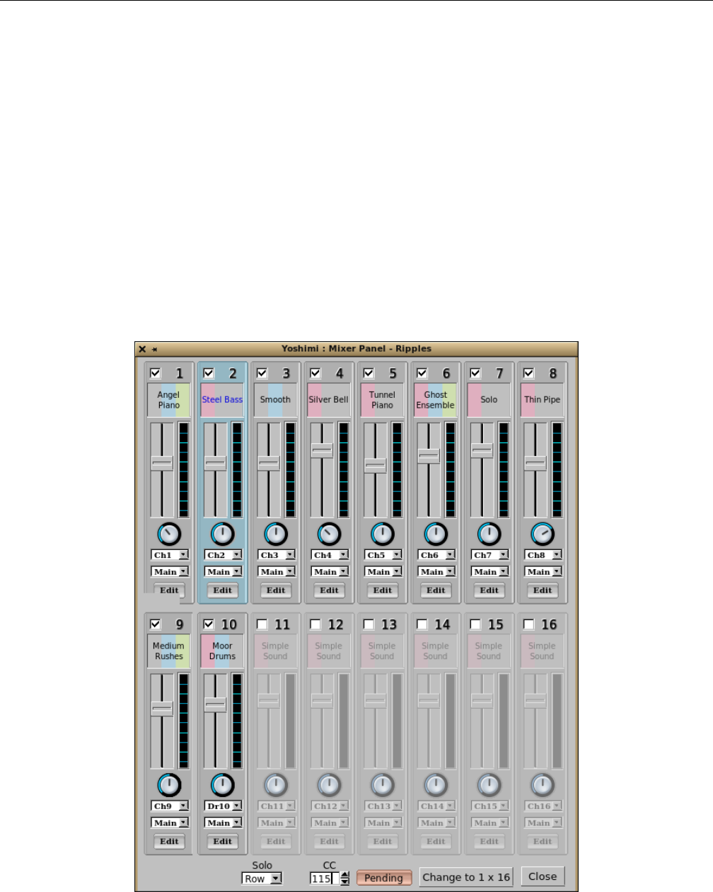
Yoshimi Software Synthesizer 7.1 Mixer Panel Window
When using the JACK audio backend, parts can be individually routed or sent to the main L/R
outputs, either by themselves, or working with the main Left and Right outputs at the same time. This
is controlled from the panel window, and the settings are saved with all the other parameters.
The individual part outputs will have the part effects, and any Insertion effects that are linked to
them, but not the System effects. Direct part outputs carry the part and insertion effects, but not system
ones.
Yoshimi used to register all parts with JACK by default, but that is a bit much now that 64 parts
are available, so now Yoshimi uses an ”on demand” model.
In the mixer panel window one will see a field just above the Edit button. This field determines the
audio destination on a part-by-part basis, defaulting to just the main L+R pair. The direct part outputs
are only exposed on parts that are active, and have the destination set to either part or both. Once
activated, they will remain in place for the entire session, even if the part is later disabled or routed to
main only. This is so that other programs won’t see links suddenly disappear, although they will become
silent. This setting is preserved in Yoshimi’s patch sets and will be re-instated when next loaded.
Figure 77: Yoshimi Mixer Panel, 2x8 View
102

Yoshimi Software Synthesizer 7.1 Mixer Panel Window
Note that there is also a 1x16 version of this dialog (not shown). This dialog has been updated
recently; there is now a Solo control, shown in the figure above and described below.
1. Part Summary. Parts View or Summary.
2. Enable part. Enable/Disable the part. The check-box enables/disables the part. When the part is
disabled, its controls are greyed out.
Values: Off*, On
3. Part name. Instrument name. Click on this box to change the instrument (it will open up the Edit
window.
4. Volume Slider. Volume Bar. Changes the volume of the part.
5. VU-meter display. Shows the level of the part when playing.
6. Panning Knob. Panning Dial-Button. Changes the panning of the part.
Values: 0 (left) to 64* (center) to 127 (right)
7. Channel. Receive from MIDI channel. Changes the MIDI channel assigned to the part.
Values: Ch1*, Ch2, ..., Ch16
8. Main. Set Audio Destination. Sets the audio for this part to be routed to the main audio output, to
the audio specified by the part setup, or to both outputs. This option requires that Yoshimi use JACK
audio. If running ALSA, this option is disabled (greyed out). The part’s audio destination (JACK) is
saved with the patch sets, and so is the number of available parts. (ZynAddSubFX will still load these
files, but it ignores any settings it doesn’t recognise. If one re-saves in ZynAddSubFX, the settings will
be lost.)
Values: Main, Part, or Both
9. Edit. The Edit button provides two function Left mouse button: Part select. Right mouse button:
Instrument edit. This setup is a bit unintuitive, but the tooltips make it clear which click one might want
to use.
10. Solo. There are two commands that change the way Yoshimi responds to incoming MIDI, so that
only one of a group of instruments will see note-on events, but all of the group will see note-off ones.
These commands are both in the Mixer Panel.
They are referred as a Solo feature or a Channel Mixer feature. The Solo settings are saved in patch
sets, which saves a little frustration when loading one’s current favorite patch set.
Values: Off*, Row, Col, Loop, TwoWay
For these modes, if one has a programmable MIDI controller, one can set it up to activate a specific
part, or to increment/decrement which part in the set is active. The Solo drop-down list enables the
feature for either Row or Column mode, and also makes the CC spin-box visible. One uses this spin-box
to set which incoming CC changes the part that gets new notes. The value this CC sends performs the
actual change, instantly and silently. Most importantly it leaves any existing notes sounding through a
note off release and the effects tail.
Row means that all of the first 16 channels will be set to channel 1, but with only one active, and
one’s CC will dial up any of the parts, disabling the others. In Row mode the whole of the first 16 parts
are ostensibly receiving on channel 1. This mode is most useful if one wants to play live through a piece
with multiple instrument changes while playing. It works best with a foot switch that internally stores a
channel number and increments/decrements it with every press, then sends it.
103

Yoshimi Software Synthesizer 7.2 Virtual Keyboard
Although this uses all of the first 16 parts, one can set the number of parts to 32, so that one
can use the 17+ row for normal 1 through 16 channels. Also, if one has vector control set up, Solo
intelligently recognises this fact, and, for each vector it finds, it will switch in/out the whole vector column
appropriately.
Note that Row is recommended only for automation.
For running Solo in Column mode, one needs to have 32 or (preferably) 64 parts set; with this
setup, one can have up to 4 parts switched per channel, and independently of each other. However, this
works more like vector control in that you have to switch in groups of 16. For example, to control the
channel 4 column one would send 4, 20, 36, 52 to select the wanted part. This usage is more appropriate
for post recording MIDI automation.
For both of these modes, if one has a programmable MIDI controller, one can set it up to activate a
specific part, or the increment/decrement which part in the set is active.
Loop. Loop mode is a variation on the Row mode. With this mode, if one sends any value (except
zero) via the designated CC, it will increment the active part by one, rolling round to 1 after 16. This
should make even the dumbest foot controller usable.
To keep it all lightweight, one needs to load and activate all the patches and parts wanted, but that
could be obtained from a saved patch set, and the channels are only changed from the very first time one
sends the CC. To look really clever, the whole lot can be embedded in a MIDI file.
One can play a piece that needs to live-switch between 10 instruments, using a footswitch to do the
channel changes. The device holds a channel number (starting with zero) and increments/decrements it
depending on which switch is pressed, then sends the resulting CC.
At the 2017 Linux Audio Conference, it became obvious there was a possible problem with the Loop
feature. This issue arose from the ’bounce’ of a cheap footswitch that would then send two changes instead
of one. It is now resolved by adding a debounce timer of about 60ms so that a second pulse inside that
time will be ignored.
TwoWay. A further development suggested at that time has now also been implemented. This is
the addition of a TwoWay option. This option works in a similar way to Loop, but a value between 1
and 63 will step down instead of up, so that if one does make a mistake it can quickly be rectified.
With a reasonable MIDI controller one can usually set a couple of foot switches to report the same
CC but with different values. Alternatively stick to their native values and pass them through something
like QmidiRoute to do the translation.
11. Parts Layout. Changes the layout of the panel to the other layout, either Change to 2 x 8 or
Change to 1 x 16.
12. Close. Close the window.
7.2 Virtual Keyboard
This section describes the detailed usage of the Yoshimi virtual keyboard. The virtual keyboard lets one
play notes using the keyboard/mouse. There is no MIDI requirement.
Using the computer keyboard: The keyboard is split into three octaves. It may happen that the keys
will not trigger a note-on; this happens when another widget has the keyboard focus. To play using the
computer keyboard, click on the virtual keyboard.
104
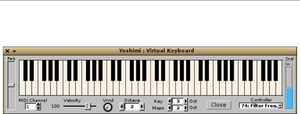
Yoshimi Software Synthesizer 7.2 Virtual Keyboard
Using the mouse: One can use the mouse to play. If one presses the Shift key while pressing the
mouse button, the keys will be not released when the mouse button is released. If one presses the Stop!
or ”panic” button from the ZynAddSubFX/Yoshimi main window, all keys are released.
Figure 78: Yoshimi Virtual Keyboard
7.2.1 Virtual Keyboard, Basics
1. Pwh
2. Midi Channel
3. Velocity
4. Velocity
5. Octave
6. Key Oct
7. Maps Oct
8. Controller
9. Cval
10. Close
13. Pwh. Pitch bend knob. Pitch wheel. This item is now a slider control. To reset it to the middle
position, right-click within the slider.
14. Midi Channel. MIDI Channel. Sets the MIDI channel for the virtual keyboard.
Values: 1* to 16
15. Velocity. Velocity of Notes. Sets the note-on velocity for the virtual keyboard.
Values: 1 to 127, 100*
16. Velocity. Velocity Randomness.
Values: 0* to 127
17. Octave. Transposes all of the virtual keyboard notes by the given number of octaves.
Values: 1, 2*, 3, 4, 5
18. Key Oct. Transposes the upper keys (the numbers and the ”qwert” keys); the range of these keys
is from C-4 to A-5 (replace the ’5’ with the octave). Look at the tooltips as a reminder.
Values: 1, 2*, 3, 4, 5
19. Maps Oct. Transposes the lower keys (”sdghj” and ”zxcvb”); the range of these keys is from C-3
to E-4 (replace the ’4’ with the octave). Look at the tooltips as a reminder.
Values: 1, 2*, 3, 4, 5
105

Yoshimi Software Synthesizer 7.2 Virtual Keyboard
20. Controller. Keyboard Controller.
Values: 01:Mod.Wheel, 07:Volume, 10:Panning, 11:Expression, 64:Sustain, 65:Portamento,
71:Filter Q, 74:Filter Freq*, 75:Bandwidth, 76:FM Gain, 77:Res.c.freq, 78:Res.bw.
Sets the controller to be changed according to the Cval controller. See Section 7.2.3 ”Virtual Key-
board, Controllers” on page 106.
21. Cval. Controller value. Changes the controller value. This item consists of two parts. The top
part shows a tiny number representing the current value of the selected controller. The bottom part is a
combination value-bar and slider that one can move up and down with the mouse, to change the controller
value. Note that the Cval value might not reflect the internal value of the controller when one changes
the controller.
Values: 1 to 127, 96*
22. Close. Close button.
7.2.2 Virtual Keyboard, ASCII Mapping
In addition to this virtual keyboard, the QWERTY (or Dvorak, or AZERTY) keyboards can be used
to produce notes. The computer keyboard layout is shown in Figure 12 ”QWERTY Virtual Keyboard
Layout” on page 36, From lowest octave to highest, the colors are blue, then green, then red. The ”white”
keys are the light colors, and the ”black” keys are the deeper colors. The range of the keys on the ”zxcvb...”
row is C3 to E4. The range of the keys on the ”qwert...” row is C4 to A5. These octave ranges can be
adjusted. The computer keyboard will produce notes only when the virtual keyboard has focus.
7.2.3 Virtual Keyboard, Controllers
This section (will give) a brief overview of the controller’s that this window supports.
1. 01: Mod. Wheel
2. 07: Volume
3. 10: Panning
4. 11: Expression
5. 64: Sustain
6. 65: Portamento
7. 71: Filter Q
8. 74: Filter Freq.
9. 75: Bandwidth
10. 76: FM Gain
11. 77: Res. c. freq
12. 78: Res. bw.
The following figure shows the corresponding drop-down list of controller values, each preceded by
its MIDI control number, re 1.
106

Yoshimi Software Synthesizer
Figure 79: Virtual Keyboard Controllers
1. Mod. Wheel. Sets the MIDI modulation value. This control will only have an effect on certain
instruments. (It has no effect on the ”Simple Sound”, for example).
2. Volume. Controls the overall volume of the instrument being played by the virtual keyboard.
3. Panning. Controls the left-right location of the sounds played by the virtual keyboard.
4. Expression. Controls the expression. This probably can have different effects depending on the
instrument. For example, with the ”Simple Sound”, this control is a lot like volume.
5. Sustain. Controls the sustain duration. This works even with the ”Simple Sound”. Using it makes
even this virtual keyboard capable of some ”virtuoso” expression.
6. Portamento. Controls the time of transition from one pitch to another. Using it makes even this
virtual keyboard capable of some ”virtuoso” expression.
7. Filter Q. Controls the sharpness of the filters used in an instrument. Generally requires a complex
instrument to take effect. For example, try this control with the ”Weird Pad” instrument in the ”Fantasy”
bank.
8. Filter Freq. Controls the center frequency of the filters used in an instrument. Generally requires a
complex instrument to take effect. For example, try this control with the ”Weird Pad” instrument in the
”Fantasy” bank.
9. Bandwidth. Controls the frequency bandwidth of the filters used in an instrument.
10. FM Gain. TODO. Haven’t found a sound that exercises this control. Haven’t looked all that hard
yet.
11. Res. c. freq. Resonance Center Frequency. Applies only if the part has resonance set up.
12. Res. bw. Resonance Bandwidth. Applies only if the part has resonance set up.
8 Effects
The Yoshimi Effects panel provides a number of special effects that can be applied to parts. Effects are,
generally, blackboxes that transform audio signals in a specified way. More exactly, the only input data
for an effect in ZynAddSubFX is an array of samples. The output is the transformed array of samples.
As described, effects have no information about anything else. For example, key presses are not
recognized. Therefore, pressing a key does not initiate the LFO. Phase knobs will always be relative to a
global LFO, dependent only on the system time.
107
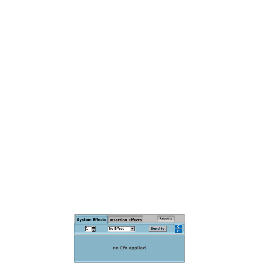
Yoshimi Software Synthesizer 8.1 Effects / Panel Types
Wetness determines the mix of the results of the effect and its input. This mix is made at the effects
output. If an effect is wet, it means that nothing of the input signal is bypassing the effect. If it is dry,
then the effect has no effect.
Interpolation means that, if one MIDI-learns the controls, one can now automate them smoothly
instead of the somewhat gritty previous behaviour. This does not change processor demand when running
at 64 frames, a short number of frames. This interpolation is especially effective on ”saw” sounds with
the frequency control on the EQ low pass filter.
The Effects panel is shown in Figure 2”Yoshimi Main Screen” on page 21. Note that these effects
have been incorporated into a separate guitar-effects project called Rakkarrak [13].
There are two types of effects: System effects and Insertion effects. The System effects apply to all
parts and allows one to set the amount of effect that applies to each part. Also, it is possible to send
the output of one system effect to another system effect. In the user interface this is shown as ”source
-<destination”. For example: The 0 -<1knob controls how much of the system effect 0 is sent to system
effect 1.
Insertion effects are described in Section 8.1.2 ”Effects / Panel Types / Insertion” on page 112.
8.1 Effects / Panel Types
There are three variations of Effects sub-panels:
•System Effects.
•Insertion Effects.
•Part/Instrument Effects.
Here are the major elements of the main effects panel, which shows the System and Insertion effects
tabs.
Figure 80: System Effects Dialog
1. System Effects Tab
2. Effect Number
3. Effect Name
4. Send to
5. C
6. P
7. Effects Panel
8. Insertion Effects Tab
9. Reports
108
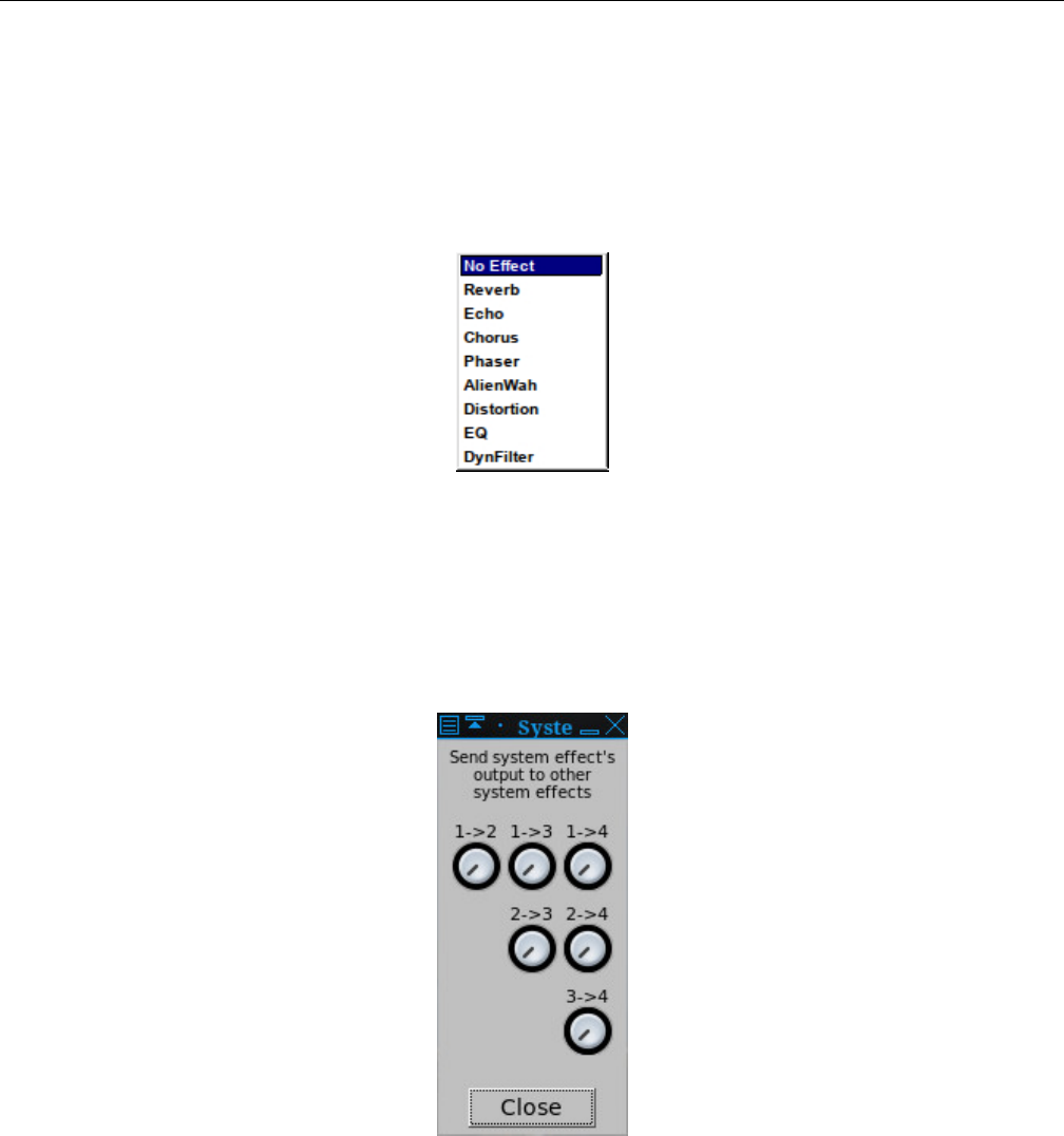
Yoshimi Software Synthesizer 8.1 Effects / Panel Types
1. System Effects Tab. System Effects Tab. The items in this tab are described in the next few
paragraphs.
2. Effect Number. Effect Number. Up to 8 effects can be supported at one time by one part.
3. Effect Name. Effect Name.
Values: No Effect*, Reverb, Echo, Chorus, Phaser, AlienWah, Distortion, EQ, DynFilter
Figure 81: Effects Names
4. Send to. Effects Send To. Each knob controls how much of the system effect indicated by the left
number is sent to the system effect indicated by the right number. This user-interface drop-down is shown
only in the Part / Edit / Effects version of the effects panel.
Values: Next Effect, Part Out, Dry Out
Figure 82: Effects, Send To
5. C. Copy-to-clipboard Dialog. We need to learn more about how this dialog gets populated.
109
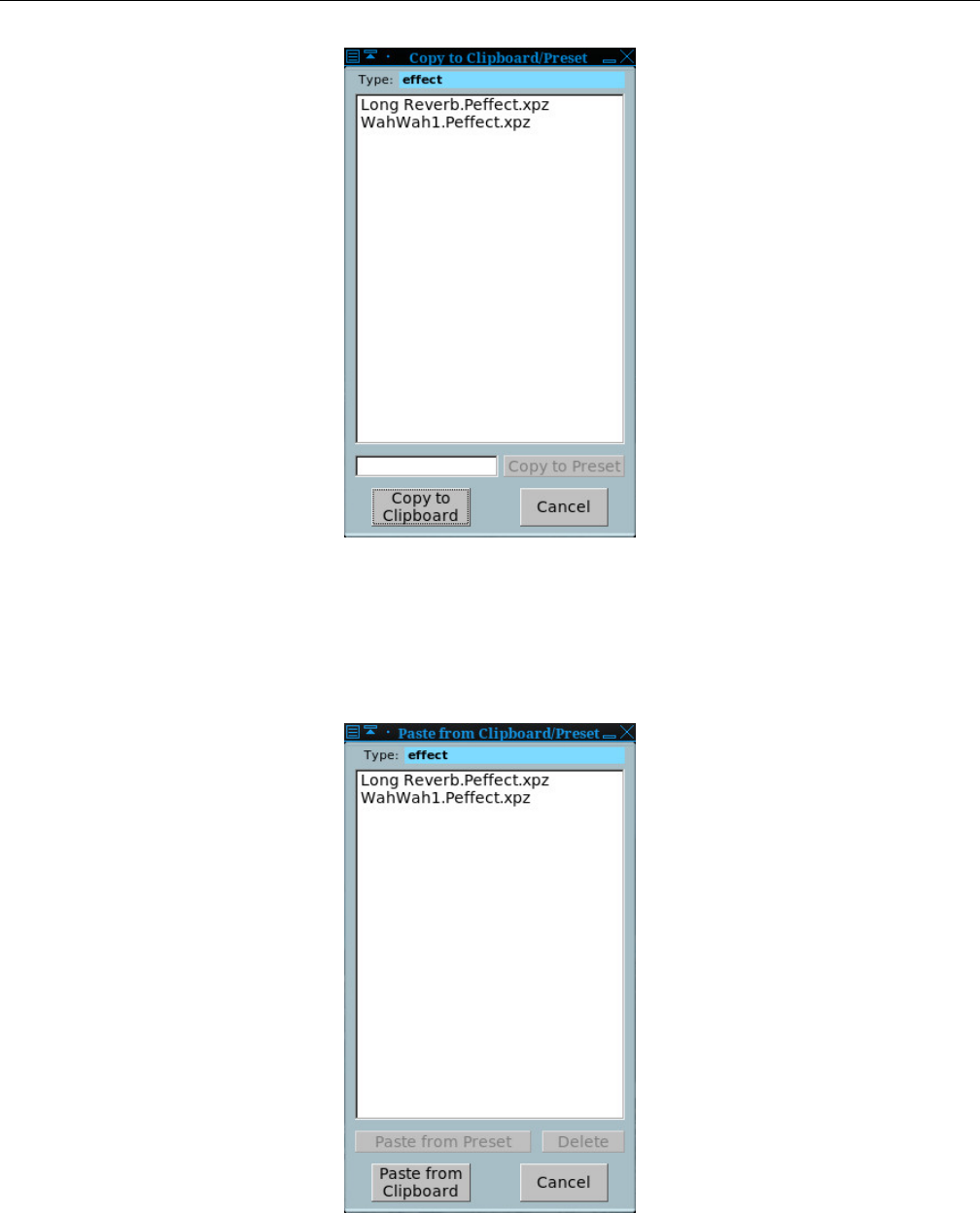
Yoshimi Software Synthesizer 8.1 Effects / Panel Types
Figure 83: Effects / Copy To Clipboard
Note that, in recent versions of Yoshimi, the Type label at the top is not ”effect”, but ”Peffect”.
What does this mean?
6. P. Paste-from-clipboard Dialog. We need to learn more about how this dialog gets populated.
Figure 84: Effects / Paste From Clipboard
7. Effects Panel. Effects Panel. This area is filled by the controls for the selected effect.
110
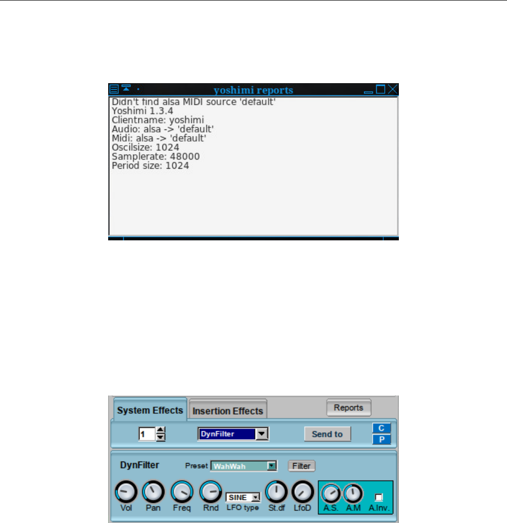
Yoshimi Software Synthesizer 8.1 Effects / Panel Types
8. Insertion Effects Tab. Insertion Effects Tab. The items in this tab are described below, in the
8.1.2 sub-section.
9. Reports. Effects Reports.
Figure 85: Effects / Reports
The next sub-sections show the variations on the effects panels, using the DynFilter effect as the
subject effects panel.
8.1.1 Effects / Panel Types / System
The first variation appears when you enable an effect in the System Effects panel of the main Yoshimi
dialog. It contains the standard controls for the given effect, plus the following interface items.
Figure 86: Sample System Effects Dialog
1. Effect number
2. Effect selection
3. Effect Filter
4. C
5. P
111
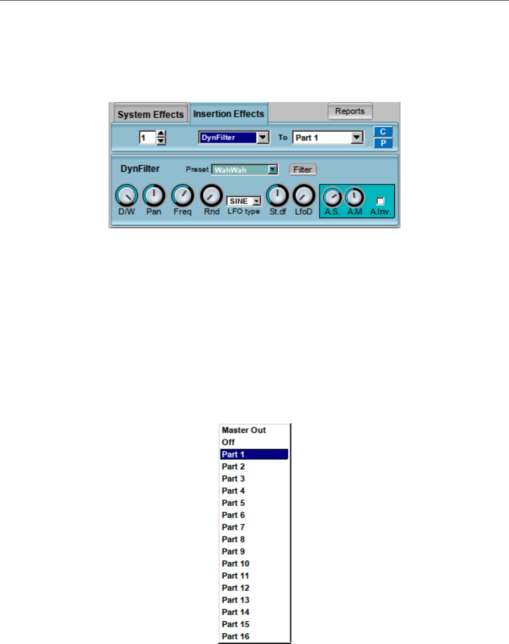
Yoshimi Software Synthesizer 8.1 Effects / Panel Types
8.1.2 Effects / Panel Types / Insertion
The second effects variation appears when you enable an effect in the Insertion Effects panel of the
main Yoshimi dialog. It contains the standard controls for the given effect, plus the following interface
items.
Figure 87: Sample Insertions Effects Dialog
1. Effect number
2. Effect selection
3. To
4. C
5. P
The insertion effects apply to one part or to the master output. One may use more than one insertion
effect for one part or the master output. If using more than one effect, the effects with smaller indexes will
be applied first (first, insertion effect 0 occurs, then effect 1, and so on). If the part selected for insertion
effect is -1 then the effect will be disabled; if the part is -2 the effect will be applied to Master Out.
1. To. Send the Effect To.
Figure 88: Part Selection Dropdown
112
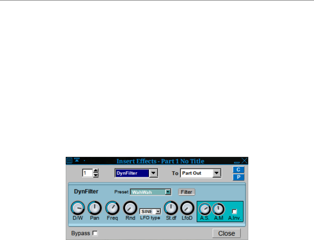
Yoshimi Software Synthesizer 8.1 Effects / Panel Types
8.1.3 Effects / Panel Types / Instrument
There is also a ”part” or ”instrument” effects window which is accessed by going to the main window,
clicking the Edit button in the bottom panel to open the edit dialog, and then clicking the Effects
button there. The part effects window has the same layout as System and Insertion effects; it is now
almost identical to Insertion effects.
It contains the standard controls for the given effect, plus the following interface items.
1. Effect number
2. Effect selection
3. To (part-selection-dropdown.png)
4. C
5. P
6. Bypass
7. Close
”To” Values: Master Out, Off, Part 1, Part 2, ..., Part 16
Figure 89: Sample Instrument Effects Dialog
Note the extra Bypass check-box. If the Bypass item is checked, then the effect is not used; it is
taken out of the circuit. This user-interface item only appears if one clicks the Edit button for a Part,
and then clicks the Effects button in the Edit window.
Also be aware that some of the effects dialogs have been modified in the latest revisions of Yoshimi.
113
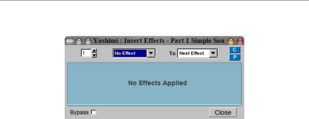
Yoshimi Software Synthesizer 8.2 Effects / None
8.2 Effects / None
Figure 90: Effects Edit, No Effect
This dialog form is reversed (top and bottom) with the latest Yoshimi, and slightly simplified in appear-
ance.
8.3 Effects / DynFilter
A dynamic filter is, as the name says, a filter which changes its parameters dynamically, dependent on
the input and current time. In ZynAddSubFX, frequency is the only variable parameter. It can be used
as an ”envelope following filter” (sometimes referenced ”Auto Wah” or simply ”envelope filter”).
8.3.1 Effects / DynFilter / Circuit
Though this filter might look a bit complicated, it is actually easy. We divide the parameters into two
classes:
•Filter Parameters are the ones obtained when one clicks on Filter. They give the filter its basic
settings.
•Effect Parameters are the other ones that control how the filter changes.
The filter basically works like this: The input signal is passed through a filter which dynamically
changes its frequency. The frequency is an additive of:
•The filter’s base frequency.
•An LFO from the effect parameters.
•The ”amplitude” of the input wave.
The amplitude of the input wave is not the current amplitude, but the so called ”Root Mean Square
(RMS)” value. This means that we build a mean on the current amplitude and the past values. How much
the new amplitude takes influence is determined by the Amplitude Smoothness (see below).
RMS value plays an important role in the term loudness. A fully distorted signal can sound 20 db
louder due to its higher RMS value. This filter takes this into account, depending on the smoothness.
114
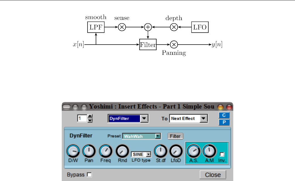
Yoshimi Software Synthesizer 8.3 Effects / DynFilter
Figure 91: Dynamic Filter Circuit Diagram
8.3.2 Effects / DynFilter / User Interface
Figure 92: Effects Edit, DynFilter
This figure shows the Part/Instrument variation of the DynFilter sub-panel. The System/Insertion vari-
ation has the following elements.
1. Preset
2. Filter
3. Vol (system/insertion) or D/W (part/instrument)
4. Pan
5. Freq
6. Rnd
7. LFO Type
8. St.df
9. LfoD
10. A.S.
11. A.M.
12. Inv.
This figure shows an additional section, in the bottom panel of the effect’s user-interface. See Sec-
tion 8.10.2 ”Effects / Reverb / User Interface” on page 130, which describes these elements in more detail.
However, it seems that all but the bypass control and the Close button have been removed from the
latest versions of Yoshimi.
1. FX No. (an unlabelled number ”wheel”)
2. bypass (bottom panel)
3. EffType (now unlabelled, obvious from context)
4. To (where the effect is sent to)
5. C
115
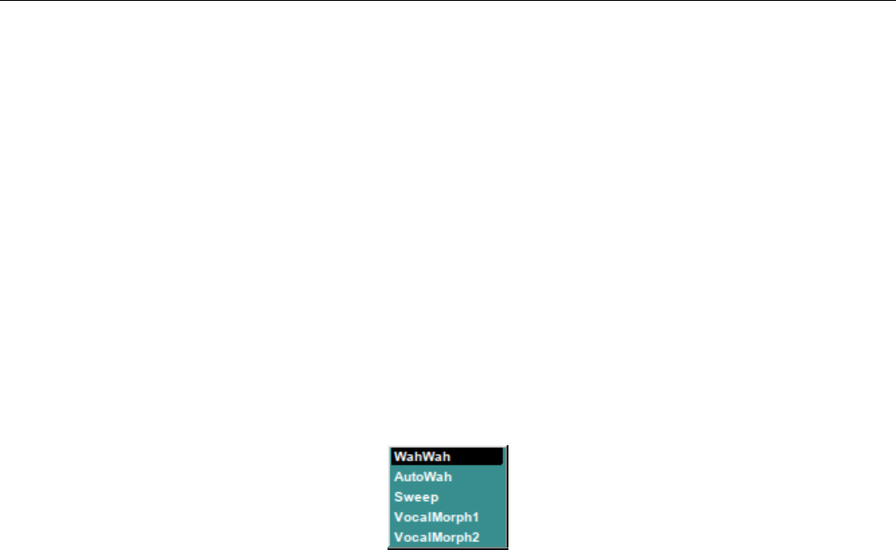
Yoshimi Software Synthesizer 8.3 Effects / DynFilter
6. P
7. Close (bottom panel)
The four controls in the middle of the middle panel (Freq,Rnd,LFO Type, and St.df ) control
the LFO.
In DynFilter, the Gain control, and most of the formant filter ones only operate as one releases
the mouse button, and the scroll wheel cannot be used at all. Investigating, it was found that this was
specifically done because these controls create significant noise when adjusted, and effects are real time,
so that’s a lot of noise. (When filters are applied elsewhere, the result is next-note so one doesn’t hear
the changes).
Which is more desirable: (1) Noise when ever the control is moved, scroll wheel capability and fully
responsive GUI; (2) Noise only when the control is released, no scroll wheel, filter graphs only updated
on control release. To be determined.
Let’s start with the user-interface elements present in the System/Insertion variation of this effect.
1. Preset. DynFilter Preset.
Figure 93: DynFilter Presets
Values: WahWah, AutoWah, Sweep, VocalMorph1, VocalMorph2
2. Filter. DynFilter Filter.
This small button brings up Filter Params stock sub-panel item. This stock user-interface item is
shown and described in Section 6.2.5 ”Filter Parameters User Interface” on page 78.
3. Vol. DynFilter Volume.
Values: 0 to 127
If the effect is used as a System effect, then this control appears.
4. D/W. DynFilter Dry/Wet Mix Setting.
Values: 0 to 127
If the effect is used as an Insertion effect, then this control appears. ”Dry” means the unprocessed
signal and ”wet” means the processed signal.
5. Pan. DynFilter Panning.
Values: 0 to 127
After the input signal has passed through the filter, Pan can apply panning.
6. Freq. DynFilter LFO Frequency.
Values: 0 to 127
7. Rnd. DynFilter LFO Randomness.
Values: 0 to 127
116

Yoshimi Software Synthesizer 8.4 Effects / AlienWah
8. LFO Type. DynFilter LFO Type.
9. St.df. DynFilter LFO. Left/right channel phase shift.
10. LfoD. DynFilter LFO Depth. This control is one that helps define the mix of the LFO and the
amplitude.
11. A.S. DynFilter A.S. This control is one that helps define the mix of the LFO and the amplitude.
A.S sets the Amplitude Sensing (i.e. how much influence the amplitude shall have).
12. A.M. DynFilter A.M. One of two knobs let one control the way how the RMS value of the
amplitudes is measured. A.M sets the Amplitude Smoothness (this is described above). The higher one
sets this value, the more slowly will the filter react.
13. Inv.. DynFilter A.Inv. One of two knobs let one control the way how the RMS value of the amplitudes
is measured. A.Inv., if set, negates the (absolute) RMS value. This will lower the filter frequency instead
of increasing it. Note that this will not have much effect if the effects input is not very loud.
8.3.3 Effects / DynFilter / NRPN Values
Effects can be controlled via ”non-registered parameter numbers”, or NRPNs. This section will eventually
(we hope) detail the NRPN values supported by the DynFilter effect.
For more information on the concept of NRPNs, see Section 21.5.3 ”Concepts / MIDI / NRPN” on
page 256.
8.4 Effects / AlienWah
AlienWah is a nice effect done by Paul Nasca. It resembles a vocal morpher or wahwah a bit, but it is
more strange. That’s why he called it ”AlienWah” The effect is a feedback delay with complex numbers.
The AlienWah effect is a special, dynamic formant filter. Paul Nasca named it AlienWah because it
sounded ”a bit like wahwah, but more strange”. The result of the filter is a sound varying between the
vocals ”Ahhhhh” (or ”Uhhhhh”) and ”Eeeeee”.
8.4.1 Effects / AlienWah / Circuit
No diagram, just a description of AlienWah.
Hint: Keep in mind that Effects that can be controlled by LFO can also be controlled arbitrarily:
Set the LFO depth to zero and manipulate the phase knob (e.g. with NRPNs or maybe via OSC in the
future).
The way that the filter moves between the two vocals is mainly described by an LFO. A bit easified,
Paul Nasca has stated the formula (for i2 = -1 and R <1) as
fb =R∗(cos(a) + i∗sin(a))
yn =yn −delay ∗R∗(cos(a) + i∗sin(a)) + xn ∗(1 −R).
The input xn has the real part of the samples from the wavefile and the imaginary part is zero. The
output of this effect is the real part of yn.ais the phase.
117
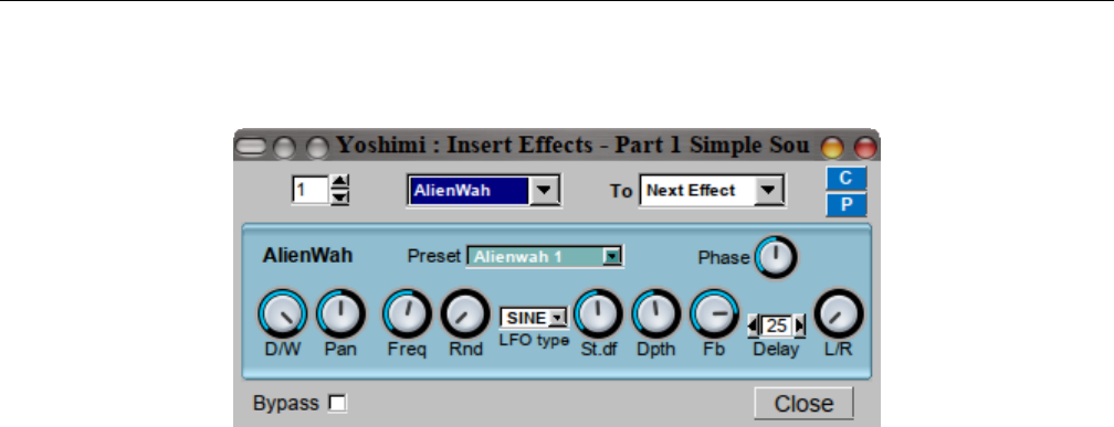
Yoshimi Software Synthesizer 8.4 Effects / AlienWah
8.4.2 Effects / AlienWah / User Interface
Figure 94: Effects Edit, AlienWah
1. Preset
2. Phase
3. Vol or D/W
4. Pan
5. Freq
6. Rnd
7. LFO type
8. St.df.
9. Dpth
10. Fb.
11. Delay
12. L/R
1. Preset. AlienWah Preset.
Values: AlienWah 1, AlienWah 2, AlienWah 3, AlienWah 4
2. Phase. The phase of the AlienWah. See ain the above formula. This lets one set where the vocal
is between ”Ahhhhh” and ”Eeeeee”.
3. Vol. AlienWah Volume.
Values: 0 to 127
The volume control is present is this effect is used as an insertion effect.
4. D/W. AlienWah Dry/Wet.
Values: 0 to 127
The Vol control is replaced by this control if the effect is used as an Insertion effect.
5. Freq. LFO Frequency.
Values: 0 to 127
Determines the LFO’s frequency in relative units.
6. Rnd. LFO Amplitude Randomness.
Values: 0 to 127
Part of the LFO definition.
118

Yoshimi Software Synthesizer 8.5 Effects / Chorus
7. LFO type. Set the LFO shape.
Values: SINE, TRI
Part of the LFO definition. Note that the LFO in other contexts has ramps and exponential shapes
that are not present here.
8. St.df. AlienWah Left/Right Chanell Phase Difference.
Values: 0 to 127
Part of the LFO definition. Sets the phase difference between LFO for left/right channels. St.df lets
one determine how much left and right LFO are phase shifted. 64.0 means stereo, higher values increase
the right LFO relatively to the left one.
9. Dpth. LFO depth.
Values: 0 to 127
Dpth is a multiplier to the LFO. Thus, it determines the LFO’s amplitude and its influence.
10. Delay. Amount of delay before the feedback.
Values: 1 to 100
If this value is low, the sound is turned more into a ”wah-wah”-effect.
11. Fb. AlienWah Feedback.
Values: 0 to 127
TODO: What is the effect of the AlienWah feedback setting?
12. L/R. Determines how the left/right channels are routed to output:
•Leftmost/0. Left to left and right to right.
•Middle/64. Left+right to mono.
•Rightmost/127. Left to right, and right to left.
L/R applies crossover at the end of every stage. This is currently not implemented for the Analog
Phaser.
13. Subtract. The output is inversed (inverted?)
8.4.3 Effects / AlienWah / NRPN Values
Effects can be controlled via ”non-registered parameter numbers”, or NRPNs. This section details the
value supported by the AlienWah effect.
8.5 Effects / Chorus
In a chorus, many people sing together. Even if each of them sings at exactly the same frequency, all their
voices usually sound different. We say they have a different timbre. Timbre is the way we perceive sound
and makes us differ between different music instruments. This is, physically, achieved by varying both the
amplitude envelope and the frequency spectrum. Multiple sounds with slightly different timbres make a
sound more shimmering, or powerful. This is called the chorus effect.
119
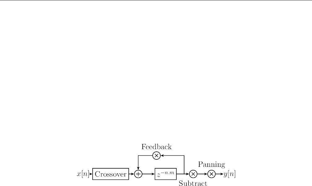
Yoshimi Software Synthesizer 8.5 Effects / Chorus
The chorus effect can be achieved by multiple people singing together. In a concert, there are many
instruments, resulting in the same effect. When making electronic music, we only have an input wave and
need to generate these different timbres by ourselves. ZynAddSubFX therefore simply plays the sound,
pitch modulated by an LFO, and adds this to the original sound. This explains the diagram below: The
multiple pitches are generated by a delayed version of the input. This version is being pitched by an LFO.
More detailed, this pitch is generated by varying the reading speed of the delayed sound; the variation
amount is controlled by an LFO.
Related effects to Chorus are Flangers. Flangers can be described as Chorus with very short LFO
delay and little LFO depth. One can imagine a flanger as two copies of a sound playing at almost the same
time. This leads to interference, which can be clearly heared. It is popular to apply flangers to guitars,
giving them more ”character”.
8.5.1 Effects / Chorus / Circuit
Figure 95: Chorus Circuit Diagram
First, crossover is applied. The Freq,Rnd,LFO Type,St.df,Depth knobs control the LFO for the
pitch. If the depth is set to zero, the pitch will not be changed at all.
Delay is the time that the delayed sound is delayed ”on average”. Note that the delay also depends
on the current pitch.
After the correct element of the sound buffer is found using the LFO, the Fb knob lets one set how
loud it shall be played. This is mostly redundant to the D/W knob, but we have not applied panning and
substraction yet.
Next, the signal can be negated. If the Subtract checkbox is activated, the amplitude is multiplied
by -1.
Finally, Pan lets one apply panning.
120
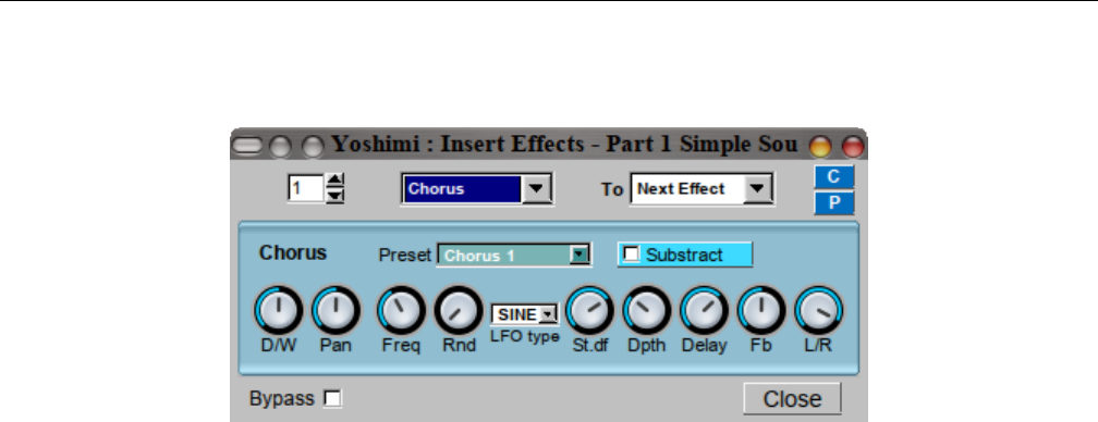
Yoshimi Software Synthesizer 8.5 Effects / Chorus
8.5.2 Effects / Chorus / User Interface
Figure 96: Effects Edit, Chorus
1. Freq
2. Rnd
3. LFO type
4. St.df.
5. Dpth
6. Delay
7. Fb.
8. L/R
9. Subtract
1. Freq. Chorus LFO Frequency.
2. Rnd. Chorus LFO randomness.
3. LFO type. Set the LFO shape.
4. St.df. The phase difference between LFO for left/right channels .
5. Dpth. Chorus LFO depth.
6. Delay. Delay of the chorus. If one uses low delays and LFO depths, this will result in a flanger effect.
7. Fb. Chorus Feedback.
8. L/R. How the left/right channels are routed to output:
1. leftmost. Left to left and right to right.
2. middle. Left+right to mono.
3. rightmost. Left to right, and right to left.
9. Subtract. The Chorus output is inversed (inverted?)
8.5.3 Effects / Chorus / NRPN Values
Effects can be controlled via ”non-registered parameter numbers”, or NRPNs. This section details the
value supported by the Chorus effect.
121
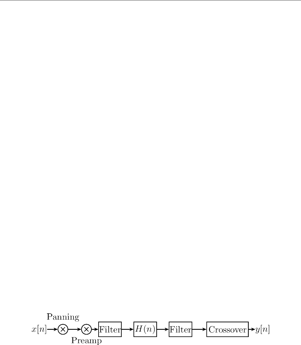
Yoshimi Software Synthesizer 8.6 Effects / Distortion
8.6 Effects / Distortion
Distortion means, in general, altering a signal. Natural instruments usually produce sine-like waves. A
wave is transformed in an unnatural way when distortion is used. The most distorted waves are usually
pulse waves. It is typical for distortion to add overtones to a sound. Distortion often increases the power
and the loudness of a signal, while the dB level is not increased. This is an important topic in the Loudness
War.
As distortion increases loudness, distorted music can cause ear damage at lower volume levels. Thus,
one might want to use it carefully. Distortion can happen in many situations when working with audio.
Often, this is not wanted. In classical music, for example, distortion does not occur naturally. However,
distortion can also be a wanted effect. It is typical for Rock guitars, but also present in electronic music,
mostly in Dubstep and DrumNBass.
The basic components of distortion are mainly
•A preamplifier.
•The waveshaping function.
•Filters.
Preamplification changes the volume before the wave is shaped, and is indeed the amount of distortion.
For example, if one clips a signal, the louder the input gets, the more distortion one will get. This can
have different meanings for different types of distortions, as described below.
The filters are practical. A reason for using them afterwards is that distortion can lead to waves with
undesired high frequency parts. Those can be filtered out using the LPF. A reason for using filters before
applying is to achieve multiband distortion. ZynAddSubFX has no ”real” multiband distortion by now,
however.
The topic of types of distortion is discussed in the Oscillator Section.
Note that one can use the Oscillator editor in order to find out what the distortion effect does.
Also note that while the Oscillator editor’s distortion is limited to some oscillators one can produce
in the Oscillator editor, the distortion effect can be used on every wave that one can generate with
ZynAddSubFX.
8.6.1 Effects / Distortion / Circuit
We explain the functionality in a diagram and list the components below.
Figure 97: Distortion Circuit Diagram
Negation is the first thing to happen. If the Neg Checkbox is activated, the amplitude is multiplied
by -1.
Panning is applied. Note, however, that one must activate the Stereo Checkbox, labelled St, before
it will work.
122
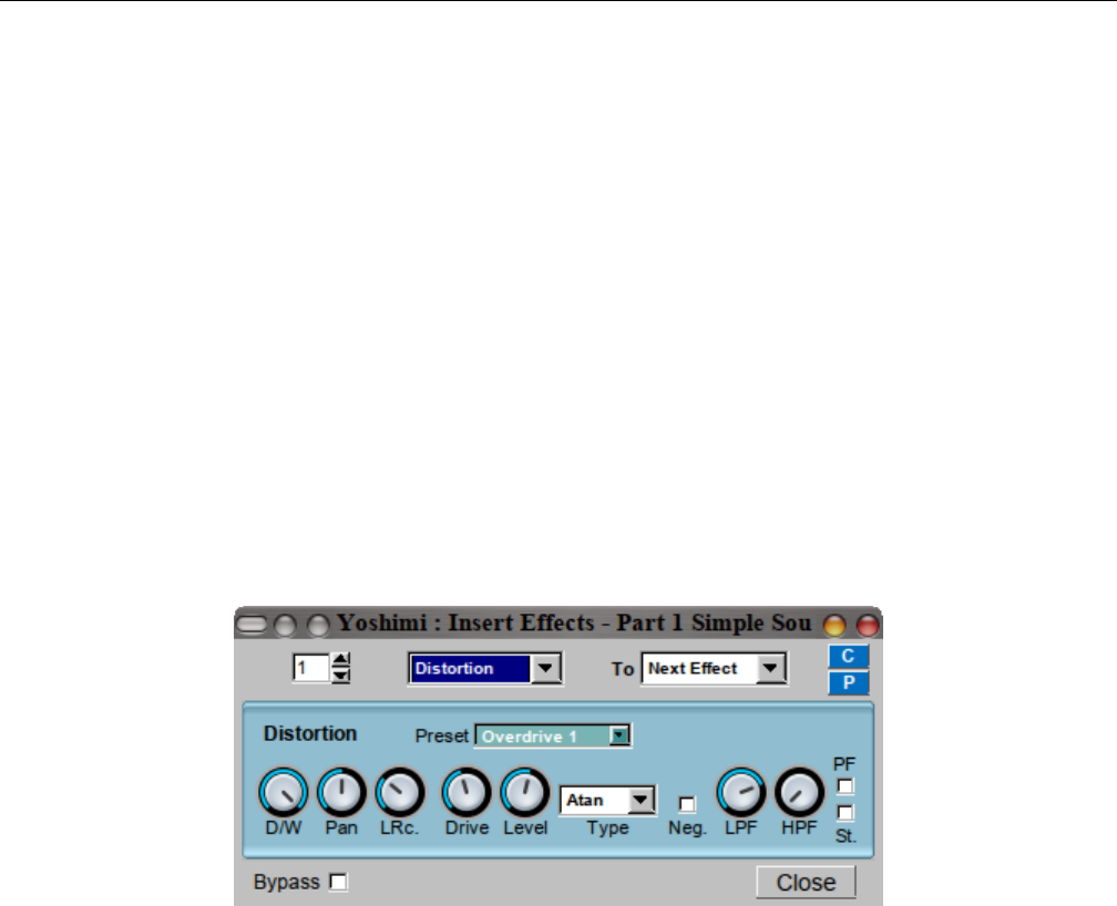
Yoshimi Software Synthesizer 8.6 Effects / Distortion
Pre-amplification is done next. The amount can be changed using the Drive nob. Indeed, this is the
amount of distortion. For example, if one clips a signal, the louder the input gets, the more distortion one
will get. This can have different meanings for different types of distortion, as described above.
HPF and LPF are filters with 2 poles. Whether they are used before or after the waveshape, depends
on the checkbox labeled PF.
The next step is the wave shape. This defines how the wave is actually modified. The Type ComboBox
lets one define how. We will discuss some types below.
After the wave shape, we scale the level again. This is called output amplification. One can change
the value using the Level knob.
Crossover is the last step. This is controlled by the knob LR Mix and means that afterwards, a
percentage of the left side is applied to the right side, and, synchronously, the other way round. It is a
kind of interpolation between left and right. If one sets the LR Mix to 0.0, one will always have a stereo
output.
8.6.2 Effects / Distortion / User Interface
Figure 98: Effects Edit, Distortion
1. Drive
2. Level
3. Type
4. Neg.
5. LPF
6. HPF
7. St.
1. Drive. Set the amount of distortion.
2. Level. Amplify or reduce the signal after distortion.
3. Type. Set the function of the distortion (like arctangent, sine).
4. Neg. Negates the amplitude (invert the signal).
5. LPF. Low Pass Filter.
6. HPF. High Pass Filter.
7. St. Set the distortion mode (stereo or mono, checked is stereo).
123
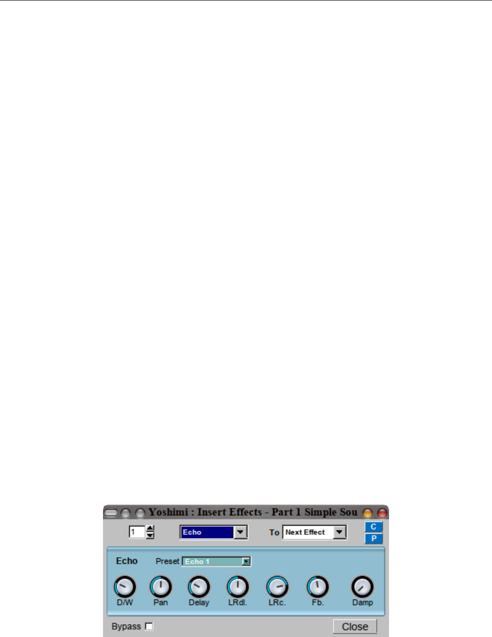
Yoshimi Software Synthesizer 8.7 Effects / Echo
8.6.3 Effects / Distortion / NRPN Values
Effects can be controlled via ”non-registered parameter numbers”, or NRPNs. This section details the
value supported by the Distortion effect.
8.7 Effects / Echo
The echo effect, also known as delay effect, simulates the natural reflection of a sound. The listener can
hear the sound multiple times, usually decreasing in volume. Echos can be useful to fill empty parts of
songs with.
8.7.1 Effects / Echo / Circuit
The good circuit diagram is shown in an old printout we have, but the current version of the Echo
description at http://zynaddsubfx.sourceforge.net/Doc/ shows a junk file. So Paul Nasca’s description
will have to suffice.
In ZynAddSubFX, the echo is basically implemented as the addition of the current sound and a
delayed version of it. The delay is implemented as in the picture below. First, we add the delayed signal
to the effect input. Then, they pass an LP1. This shall simulate the effect of dampening, which means
that low and especially high frequencies get lost earlier over distance than middle frequencies do. Next,
the sound is delayed, and then it will be output and added to the input.
The exact formula in the source code for the dampening effect is as follows:
Y(t) = (1 −d)∗X(t) + d∗Y(t−1)
where t be the time index for the input buffer, d be the dampening amount and X,Y be the input,
respective the output of the dampening. This solves to
Y(z) = Z(Y(t)) = (1 −d)∗X(z) + d∗Y(z)∗z−1<==> H(z) = Y(z)X(z)=1−d1−d∗z−1
which is used in Y(z) = H(z)∗X(z). So H(z) is indeed a filter, and by looking at it, we see that it
is an LP1. Note that infinite looping for d=1 is impossible.
8.7.2 Effects / Echo / User Interface
Figure 99: Effects Edit, Echo
124
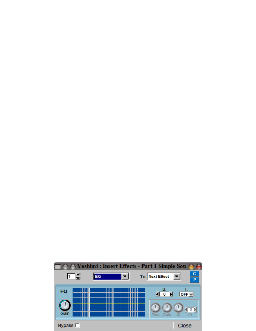
Yoshimi Software Synthesizer 8.8 Effects / EQ
TODO (yoshimi): Pan lets one apply panning of the input.
1. Delay
2. LRdl.
3. LRc.
4. Fb.
5. Damp
1. Delay. The delay time of one echo.
2. LRdl. Left-Right-Delay. The delay between left/right channels. If it is set to the middle, then both
sides are delayed equally. If not, then the left echo comes earlier and the right echo comes (the same
amount) later than the average echo; or the other way round. Set the knob to 0 to hear on the right first.
3. LRc. Echo Crossover. The ”crossing” between left/right channels.
4. Fb. Echo feedback. Feedback describes how much of the delay is added back to the input. Set Fb.
to the maximum to hear an infinite echo, or to the minimum to just hear a single repeat.
5. Damp. Echo damping. How high frequencies are damped in the Echo effect. The Damp value lets
the LP1 reject higher frequencies earlier if increased.
8.7.3 Effects / Echo / NRPN Values
Effects can be controlled via ”non-registered parameter numbers”, or NRPNs. This section details the
value supported by the Echo effect. TODO.
8.8 Effects / EQ
EQ is a parametric equalizer. An equalizer is a filter effect that applies different volume to different
frequencies of the input signal. This can, for example, be used to ”filter out” unwanted frequencies.
ZynAddSubFX’s implementations follow the ”Cookbook formulae for audio EQ” ([5]) by Robert Bristow-
Johnson.
On the equalizer graph there are 3 white vertical bars for 100Hz, 1kHz, 10kHz.
8.8.1 Effects / EQ / Circuit
8.8.2 Effects / EQ / User Interface
Figure 100: Effects Edit, EQ
125

Yoshimi Software Synthesizer 8.8 Effects / EQ
We describe all parts of the GUI here. The term passband (or often just ”band”) refers to the amount of
frequencies which are not significantly attenuated by the filter.
1. Gain
2. Graph
3. B
4. T
5. Freq
6. Gain
7. Q
8. St
Global:
1. Gain. Amplifies or reduce the signal that passes through EQ.
2. Graph. Shows the graph of the EQ frequency response, based on the two Gain settings, T.,Gain,
Gain,
3. B. Set the current frequency band number (or filter). B lets one choose the passband number.
Multiple passbands define one filter. This is important if one wants multiple filters to be called after each
other. Note that filters are commutative.
Values: 0*, 1, ... 7
Bands:
4. T. Set the type of the filter.
Values: Off*, Lp1, Hp1, Lp2, Hp2, Bp2, N2, Pk, Lsh, Hsh
Note that, for certain values of the Bparameter, some of the Tvalues will not be available.
5. Freq. The frequency of the filter. Freq describes the frequencies where the filter has its poles. For
some filters, this is called the ”cutoff” frequency. Note, however, that a bandpass filter has two cutoff
frequencies.
6. Gain (Filter). The gain of the filter. Gain is only active for some filters (Pk,Lsh, and Hsh, and it
sets the amount of a special peak these filters have. Note that for those filters, using the predefined gain
makes them effectless.
7. Q. The Q (resonance, or bandwidth) of the filter. Resonance lets one describe a peak at the given
frequency for filters with 2 poles. This can be compared to real physical objects that have more gain at
their resonance frequency.
8. St. Number of additional times the filter will be applied (in order to do very steep roll-off - eg. 48
dB/octave). St. lets one define multiple filter stages. This is equivalent to having multiple copies of the
same filter in sequence.
Values: 0*, 1, ... 4
8.8.3 Effects / EQ / NRPN Values
Effects can be controlled via ”non-registered parameter numbers”, or NRPNs. This section details the
value supported by the EQ effect.
TODO.
126
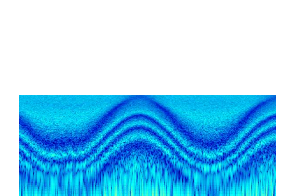
Yoshimi Software Synthesizer 8.9 Effects / Phaser
8.9 Effects / Phaser
The Phaser is a special dynamic filter. The result is a sweeping sound, which is often used on instruments
with a large frequency band, like guitars or strings. This makes it typical for genres like rock or funk,
where it is often modulated with a pedal, but also for giving strings a warm, relaxing character.
8.9.1 Effects / Phaser / Circuit
We have no circuit diagram, just a picture of the results of the phaser effect in the form of a spectrogram.
Figure 101: Phaser Circuit Spectrogram
The audio signal is split into two paths. One path remains unchanged. The other one is sent to a
delay line. The delay time (the so-called phase) is made dependent on the frequency. Therefore, an all-pass
filter is applied to the signal, which preserves the amplitude, but determines the delay time. In the end,
both paths are added.
The spectrogram describes how this works on white noise. Light blue indicates that the frequency
is not present at the current time, and dark blue indicates the opposite. The dark blue peaks appear if
the delay time is very short, because then, the second path almost equals the first one, which results in
duplication of the signal. If the delay line is very long, then it is – in the case of white noise – totally at
random whether the delayed signal currently duplicates the unchanged path, or whether it cancels it out
to zero. This random effect results in white noise between the clear blue structures.
ZynAddSubFX offers different types of phasers:
•Analog and ”normal” phasers. Analog phasers are more complicated. They sound punchier,
while normal phasers sound more fluently. However, analog filters usually need more filter stages to
reach a characteristic sound.
•Sine and triangle filters. Note that an analog triangle filter with many poles is a barber pole
filter and can be used to generate Shepard Tones, i.e. tones that seem to increase or decrease with
time, but do not really.
•The LFO function can be squared. This converts the triangle wave into a hyper sine wave. The
sine squared is simply a faster sine wave.
127
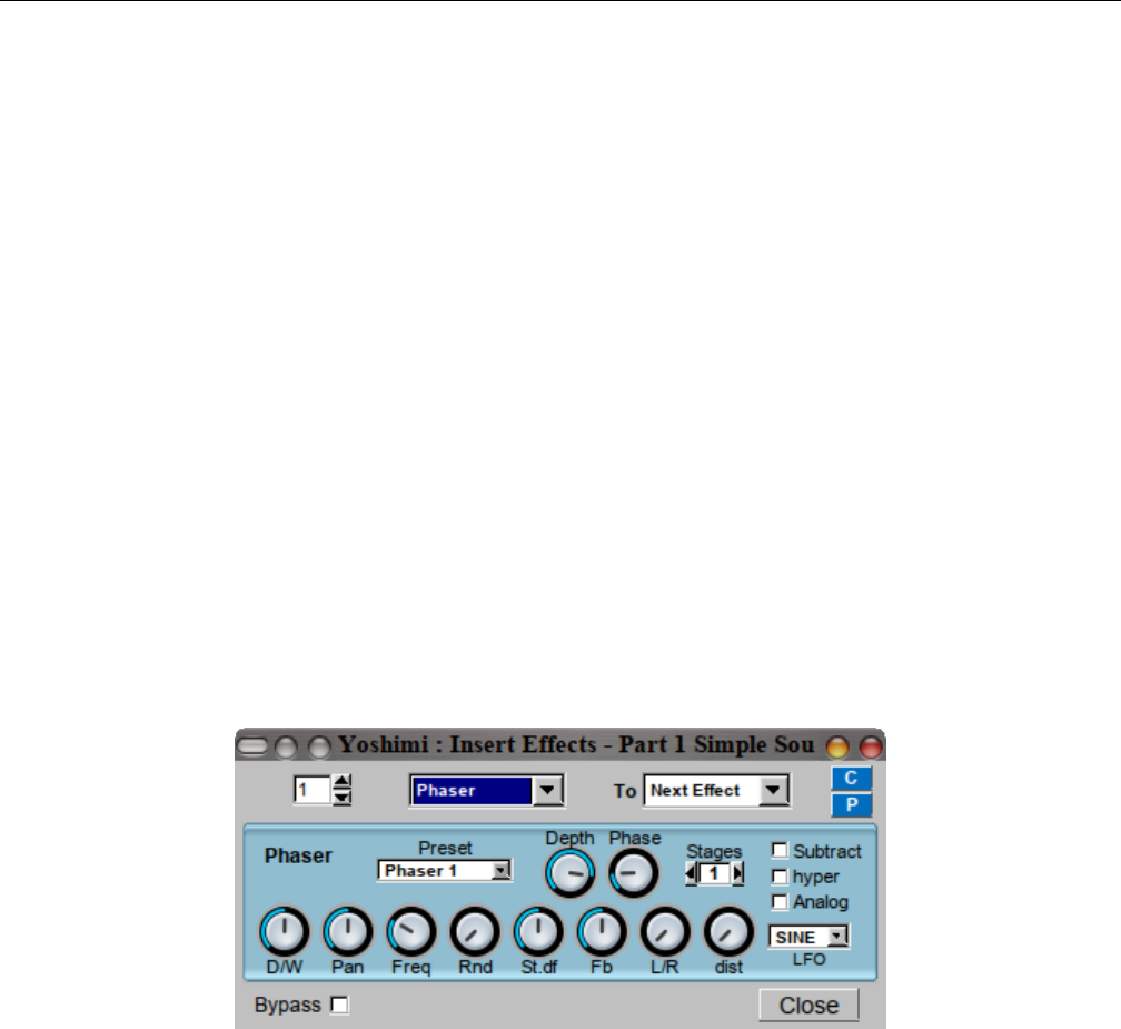
Yoshimi Software Synthesizer 8.9 Effects / Phaser
For the normal phaser, Figure 102 ”Effects Edit, Phaser” on page 128, below, shows the controls
referred to in this list of steps.
1. First, the LFO is generated. There are 4 controls (Freq,Rnd,LFO type, St.df) that define the
LFO.
2. Phase and Depth are applied afterwards in the usual way. For the analog phaser (see the Analog
check-box), Phase is not implemented yet.
3. If hyper is set, then the LFO function is squared.
4. Next, the input is used.
5. The Analog setting decides whether the phaser is analog or ”normal”.
6. Pan applies panning to the original input in every loop.
7. Next, barber-pole phasing is applied (Analog only).
8. Fb applies feedback. The last sound buffer element is (after phasing) multiplied by this value and
then added to the current one. For the normal filter, the value is added before, and, for analog, after
the first phasing stage.
9. Next, based on the setting of Stages, phasing stages are applied. The dist control sets the amount
of distortion when applying the phasing stages. This setting has only effect for analog phasers.
10. The feedback is applied next, for analog filtering.
11. In the end, the Substract option inverts the signal, multiplying it by -1.
8.9.2 Effects / Phaser / User Interface
Figure 102: Effects Edit, Phaser
1. Preset.
2. Depth
3. Phase
4. Stages
5. Subtract
6. hyper
7. Analog
8. D/W
9. Pan
10. Freq
11. Rnd
12. St.df
13. Fb
128

Yoshimi Software Synthesizer 8.9 Effects / Phaser
14. L/R
15. dist
16. LFO
The extra fields that are shown if the effect is an insertion effect are not shown. They are still need
to be described.
9. Preset. Phaser Presets.
Values: Phaser 1, ...
10. Depth. Phaser Depth. Phaser LFO Depth?
Values: 0% to 100%
11. Phase. Phaser Phase.
Values: 0% to 100%
12. Stages. Phaser Stages.
Values: 1*, 2, ... 12
13. Subtract. Phaser Subtract. Checking this box inverts the output.
Values: Off*, On
14. hyper. Phaser Hyper. Checking this box sets the ”hyper-sine” mode, whatever that is.
Values: Off*, On
15. Analog. Phaser Analog. Checking this box emulates the ”FET”. Field-effect transistor?
Values: Off*, On
16. D/W. Phaser Dry/Wet. This knob sets the effect volume. The dry value ranges from 0 dB down to
”inf” (infinity) dB, while the wet values is the complementary range, from ”inf” dB to 0 dB. Confusing?
The tooltip tells the user exactly what the settings are.
17. Pan. Phaser Panning. Ranges from 100% left to centered to 100% right.
18. Freq. Phaser Freq. Set the Phaser LFO frequency. Ranges from 0.0 Hz to 30.68 Hz.
19. Rnd. Phaser Randomness. Set the Phaser LFO randomness. Ranges from 0.0% to 100% percent.
20. St.df. Left/Right Channel Phase Shift. The phase difference between LFO for left/right channels.
Ranges from -180 degrees (left 180) to equal to +180 degrees (right 180). The actual end values can differ
a little from 180.
21. Fb. Phaser Feedback. Ranges from -99% to 99%.
22. L/R. L/R. How the left/right channels are routed to output:
1. leftmost. Left to left and right to right.
2. middle. Left+right to mono.
3. rightmost. Left to right, and right to left.
23. dist. Phaser Distortion. Ranges from 0% to 100%.
24. LFO. Phaser LFO Type.
Values: SINE, TRI
129
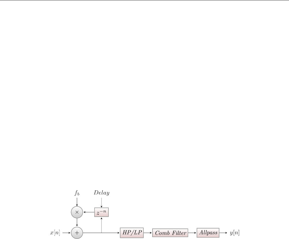
Yoshimi Software Synthesizer 8.10 Effects / Reverb
8.9.3 Effects / Phaser / NRPN Values
Effects can be controlled via ”non-registered parameter numbers”, or NRPNs. This section details the
value supported by the Phaser effect.
8.10 Effects / Reverb
A Reverberation actually expresses the effect of many echoes being played at the same time. This can
happen in an enclosed room, where the sound can be reflected in different angles. Also, in nature, thunders
approximate reverbs, because the sound is reflected in many different ways, arriving at the listener at
different times.
In music, reverbs are popular in many ways. Reverbs with large room size can be used to emulate
sounds like in live concerts. This is useful for voices, pads, and hand claps. A small room size can simulate
the sound board of string instruments, like guitars or pianos.
8.10.1 Effects / Reverb / Circuit
As mentioned, a reverb consists of permanent echo. The reverb in ZynAddSubFX is more complex than the
echo. After the delaying, comb filters and then allpass filters are being applied. These make the resulting
sound more realistic. The parameters for these filters depend on the roomsize. For details, consider the
information about Freeverb.
Figure 103: Reverb Circuit Diagram
8.10.2 Effects / Reverb / User Interface
The user-interface for the Reverb effect depends on whether it is used as a System effect or an Insertion
effect. Observr Figure 104 ”Effects Edit, Reverb” on page 131, where the Insertion mode is shown. In
the System mode, only the light-blue portion of the user-interface appears.
130
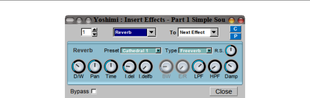
Yoshimi Software Synthesizer 8.10 Effects / Reverb
Figure 104: Effects Edit, Reverb
1. Preset
2. Type
3. R.S.
4. D/W
5. Pan
6. Time
7. I.del
8. I.delfb
9. BW
10. E/R
11. LPF
12. HPF
13. Damp
There is a fourth type we have screen captures for, but we can’t seem to navigate to them now! Are
these now out-of-date screen captures?
1. FX No.
2. bypass
3. EffType
4. Send To
5. C
6. P
7. Close
1. Preset. Reverb Preset.
131
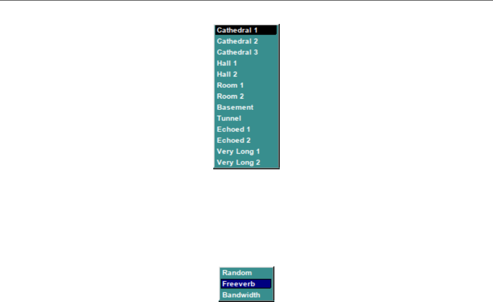
Yoshimi Software Synthesizer 8.10 Effects / Reverb
Figure 105: Reverb Preset Dropdown
Values: Cathedral 1, Cathedral 2, Cathedral 3, Half 1, Half 2, Room 1, Room 2, Basement,
Tunnel, Echoed 1, Echoed 2, Very Long 1, Very Long 2
2. Type. Reverb Type. The combobox lets one select a reverb type.
Figure 106: Reverb Type Dropdown
•Freeverb is a preset. It was proposed by Jezar at Dreampoint.
•Bandwidth has the same parameters for the comb and allpass filters, but it applies a unison before
the LPF/HPF. The unison’s bandwidth can be set using BW.
•Random chooses a random layout for comb and allpass each time the type or the roomsize is being
changed.
Values: Random, Freeverb, Bandwidth
3. R.S. Reverb Room Size. The room size defines parameters only for the comb and allpass filters.
4. D/W. Reverb Dry/Wet Setting. This setting controls much of the original signal is mixed with the
reverb effect.
5. Pan. Reverb Panning. Pan lets one apply panning. This is the last process to happen.
6. Time. Reverb Time. Set the duration of late reverb. Time controls how long the whole reverb shall
take, including how slow the volume is decreased.
7. I.del. Reverb Initial Delay. The initial delay (I.del) is the time which the sounds need at least to
return to the user.
8. I.delfb. Reverb Initial Delay Feedback. Sets the initial delay feedback. The initial delay feedback
(I.delfb) says how much of the delayed sound is added to the input. It is not recommended to use this
setting together with low initial delays).
9. BW. Reverb Bandwidth.
10. E/R. Reverb E/R. Echo Reflection? TODO!
11. LPF. Reverb Lowpass Filter. This filter is applied before the comb filters.
132

Yoshimi Software Synthesizer
12. HPF. Reverb Highpass Filter. This filter is applied before the comb filters.
13. Damp. Reverb Damp. Damp determines how high frequencies are damped during the reverberation.
The dampening control (Damp) currently only allows to damp low frequencies. Its parameters are used
by the comb and allpass filters.
14. FX No. Reverb FX Number.
Values: 1 to 8?
15. bypass. Reverb FX Bypass.
Values: Off*, On
16. EffType. Reverb Effect Type.
Values: Reverb, EQ, Echo, etc. TODO
17. Send To. Reverb Send To. This user-interface drop-down is shown only in the Part / Edit /
Effects version of the effects panel.
Values: Next Effect, Part Out, Dry Out
18. C. Reverb Copy.
19. P. Reverb Paste.
20. Close. Close Window.
8.10.3 Effects / Reverb / NRPN Values
Effects can be controlled via ”non-registered parameter numbers”, or NRPNs. This section details the
values supported by the Reverb effect.
TODO: detail the values supported by the Reverb effect.
9 Bottom Panel
9.1 Bottom Panel Controls
The Yoshimi bottom panel provides quick access to some major features of the application. The bottom
panel is shown in Figure 2”Yoshimi Main Screen” on page 21.
Here are the major elements of the bottom panel.
1. Part
2. of
3. Instrument Name
4. Edit (Instrument Edit Button)
5. Midi
6. Mode
7. Enabled
8. Portamento
9. Velocity Sens
10. Velocity Offset
11. Pan
133

Yoshimi Software Synthesizer 9.1 Bottom Panel Controls
12. Volume
13. Controllers
14. Minimum Note
15. Maximum Note
16. m
17. R
18. M
19. Key Shift
20. Key Limit
21. System Effect Sends 1
22. System Effect Sends 2
23. System Effect Sends 3
24. System Effect Sends 4
25. Sound Meter
1. Part. Part Number.
Values: 1 to 16; 1 to 32; 1 to 64
Show and set current part. The maximum number of values depends on the Part of selection.
2. of. Maximum Number of Parts.
Values: 16*, 32, 64
Yoshimi now has up to 64 parts in blocks of 16. One can now decide how many one wants to have
available using this user-interface item. By default these are wrapped around the normal MIDI channels,
so that parts 1, 17, 33, and 49 all respond to channel 1 messages. This was originally implemented for
Vector Control, working with up to four sounds on a channel (similar to the Yamaha SY hardware series).
However, these additional parts have other less obvious uses. One of these is getting far more than
16 completely independent tracks addressed by just the 16 channels. Most tunes run with instruments
having a relatively narrow pitch range, and this is what we can make use of.
As an example, in Yoshimi’s main window select 64 parts, then on part 1 set (say) ’Steel Bass’ and
maximum note as 52 (E). Next select part 17 and enable it (easiest to use the mixer panel for this) set
’Tunnel Piano’, the minimum note as 53 and maximum as 71 (B). Finally, enable part 33, set ’Rushes’,
and set its minimum note as 72, but key shift down an octave. With a 61 note keyboard that gives one
quite a useful working range, on just one channel.
However, the idea really comes into its own with a sequencer like Rosegarden where one can record
multiple parts over the full MIDI range and track them to the same channel. Also, in Rosegarden the
parts can be separately named, and identified as ’Bass’ and ’Treble’ in the notation editor. This setup
makes it very convenient for those wanting a more formal musical layout.
So, with very little effort, one can now have 48 tracks playing at once! Ummm, one does need a decent
processor though :) Yes, one could run more instances of Yoshimi on different MIDI ports, but where’s
the fun in that?
Another possibility is obtaining very smooth transitions between different sounds on the same channel.
If one uses program change to do this, that part has to be muted, and there is a variable time lag (while
the new part is loaded) before one can play any more notes on that channel. However, with 32 and 64
parts one can actually overlap notes with different instruments on a playing channel.
This setup is accomplished by pre-loading the wanted instruments, then switching channel numbers.
If (via the direct part NRPN) one adds 16 to a sounding part’s channel number, it will then only respond to
134

Yoshimi Software Synthesizer 9.1 Bottom Panel Controls
Note Off events. To bring it back into operation simply restore the original channel number. An example:
1. Enable 32 parts.
2. Load ’Simple Chimes’ into part 0 (part 1 in the GUI).
3. Load ’Silver Bell’ into part 16 (part 17 in the GUI).
4. In your sequencer, via direct part NRPN set part 16 to channel 16. This will now be ’whited out’
in the GUI.
5. Record some notes to channel 0 (1 in human-readable terms).
6. In the sequencer, just before the first note that one wants to sound as ’Silver Bell’, insert two direct
part NRPNs, with one to set part 0 to channel 16, and the other to set part 16 to channel 0.
Now, when played through, the last ’Simple Chimes’ note will have its full release and reverb tail,
blending into the first ’Silver Bell’ note. To go back to using ’Simple Chimes’ just reverse the NRPNs.
The only time this gets complicated is if the new note is exactly the same pitch as the old one, in which
case the NRPNs need to be between the old note-off and the new note-on.
By default, all the upper parts (numbers greater than 16) are mapped to the same MIDI channel
numbers as the lowest ones, but have independent voice and parameter settings. They cannot normally
receive independent note or control messages. However, vector control will intelligently work with however
many one has set, as will all the NRPN direct part controls. See Section 16.3 ”Vector / Vector Control”
on page 200.
This item is a fairly new feature of Yoshimi (as of version 1.3.5).
3. Instrument Name. Instrument Name. Left-click to open the Bank window. Right-click to change
the name of the current instrument. One needs to change only one character to make the instrument
name savable. If one goes into the instrument editor and changes engine controls, then ’Simple Sound’
gets changed to ’No Title’, and this change can be saved. Blocking the saving of ’Simple Sound’ was done
for two reasons. Initially there was no name at all by default, and people were saving them like that. The
problem then was once re-loaded you had no idea what was there, or even if there was anything at all
except the basic sound. Also, to save time and space, when saving patch set or state files, no ’empty’
instruments are included, and that name is a quick way to identify such an instrument; the alternative
would be to compare every single element of the instrument against it’s default setting.
If one changes the name of the instrument, be sure to select Menu / Instrument / Save Instru-
ment to preserve that change.
The name now has color-coding to indicate the instrument’s use of ADDsynth, SUBsynth, or PADsynth.
One can see the ”red” color for ADDsynth in the figure for the bottom panel. ”Blue” would indicate SUB-
synth, and ”green” would indicate PADsynth.
4. Edit. Instrument Edit button. This button brings up the instrument-edit dialog shown in Figure 109
”Part Edit (Instrument) Dialog” on page 141.
This dialog provides a very broad overview of the instrument, and provides access to far more detailed
dialogs to edit the instrument. This dialog is explained in detail in Section 9.3 ”Bottom Panel Instrument
Edit” on page 141.
There are some additional tricks to this button. From the main window there are shortcuts to go
directly to the Add, Sub, and Pad editors (in kit mode this only applies to item 1). Holding down A,S,P,
for AddSynth, SubSynth, and PadSynth, respectively, while left-clicking the Edit button, will open their
respective editors, but only if the desired engine is enabled; otherwise, the keystroke will be ignored, but
the normal part-edit window will come up.
135

Yoshimi Software Synthesizer 9.1 Bottom Panel Controls
Using the right mouse button to click will enable the engine and then open the editor. The same is
true with Sfor SUBSynth and Pfor PADSynth.
Dcan be used as an alternative to P, which is nice for QWERTY keyboards. This is not perfect, and
if one’s timing is a bit quick it might miss, and just open the normal part selection window.
Holding down the Kkey then clicking will open the Kit editor. The Ekey opens the part’s Effects
window.
5. Midi. MIDI Channel.
Values: 1 to 16
6. Mode. Note-generation mode. Sets the mode (polyphonic/monophonic/legato). In Polyphonic mode,
multiple simultaneous notes are supported. In Monophonic mode, only one note is supported. In Legato
mode, the sound flows smoothly from note to note without any breaks. This mode is particularly effective
with Portamento. If one uses the foot-pedal CC to enable it, the text in the Mode icon will show this
status, and then will drop back to whatever it was previously when the pedal is released.
However, one cannot have legato mode and drum mode (see Section 13 ”Kit Edit” on page 183)
at the same time. If drum mode is set when trying to enable legato, drum mode takes priority, and the
”Legato” label will be shown in red. Cancelling drum mode makes legato valid, and the ”Legato” label
will turn black again. If using a legato MIDI pedal, Yoshimi’s part mode will show the legato change, and
will set the label red if an instrument in drum mode is on in that part.
Values: Poly, Mono, Legato
7. Enabled. Enable the part. If the Part is disabled it doesn’t use CPU time.
Values: Off*, On
8. Portamento. Enable/disable the portamento. One can set the duration and other parameters by
opening the Controllers window.
Values: Off*, On
9. Velocity Sens. Velocity Sensing Function.
Values: 0 to 127, 64*
10. Velocity Offset. Velocity Offset.
Values: 0 to 127, 64*
11. Pan. Pan.
Values: 0 to 127, 64*
12. Volume. Instrument Volume.
Values: 0 to 127, 96*
The default volume for ADD parts (overall) and SUB parts is 96; the default volume for SUB parts
is 90; the ADD voice volumen is 100; and effects volumes vary heavily with the effect.
13. Minimum Note. Minimum note the part receives.
Values: 0* to 127
14. Maximum Note. Maximum note the part receives.
Values: 0 to 127*
15. m. Minimum Note Capture Button.
136

Yoshimi Software Synthesizer 9.1 Bottom Panel Controls
Set minimum note to last note played.
16. R. Minimum and Maximum Note Reset Button.
Reset the minimum key to 0 and the maximum key to 127.
17. M. Maximum Note Capture Button. Sets the maximum note to the last pressed key.
18. Key Shift. Key Shift. This value is like the master Key Shift in the top panel, but it applies only
to the current part active in the bottom panel. In recent versions of Yoshimi, it has been extended to a
larger semitone range. Also note that the key shift can be set via the user-interface, the command-line, or
by MIDI NRPN commands. With NRPN, this part shift can be set by direct part control or by channel
number.
Values: -36 to 36, 0*
Also see the Key Shift item in Section 7”Top Panel” on page 100for more information.
19. Key Limit. Maximum keys to be allocated for this part.
Values: 0 to 60, 20*
20. System Effect Sends 1, 2, 3, and 4.
TODO: Describe how these sends work.
Values: 0 to 127*
21. Sound Meter. VU Meter. Sound Meter.
This discussion of ”Audio Output and Levels” comes from Output Levels.txt.
At the bottom of the main window there is a pair of horizontal grids representing a bargraph type
display. The upper one is for the left hand channel and the lower one for the right hand one. The grid
divisions each represent 1 dB, and the brighter divisions are therefore 5 dB. The thicker bright divisions
therefore being 10 dB. The overall scale range is -48 dB to 0 dB.
As the output level rises pale blue strips will light up in these grids. These fast responding bars are
the peak levels and should never be allowed to go above 0 dB, otherwise the output is likely to be clipped
and distorted. There is also a pair of boxes on the end of these grids which will show the highest peak
level seen. If clipping has happened the box background will change from black to red. To clear the clip
and peak level indication, click on this area.
As well as the peak level, the display shows a much slower responding RMS level, as a yellow line on
top of the blue bar. This gives and indication of the apparent accoustic power.
If one opens the panel window one will see vertical bargraphs for each individual part. On these, the
faint bars are 5dB steps and the bright ones 10dB. The peak level isn’t shown numerically, but if one
exceeds 0dB a thick red line will appear at the top of the bargraph. This is also cleared from the box in
the main window.
9.1.0.1 Tip: Using the VU Meter
The VU meter topic is very interesting, because one of the problems is a tendency to overdrive it by way
of sustain pedal. At the last test, it showed up in the output before it showed up in the VU meter, so the
VU meter will help a lot in analysis.
One way to avoid overdrive is to keep polyphony to 20 on each patch (two or three patches per
Yoshimi instance, with two or three Yoshimi simultaneous instances depending on the patch). Another
item which helps a lot is compression (for example, the Calf multiband compressor is amazingly good.
137
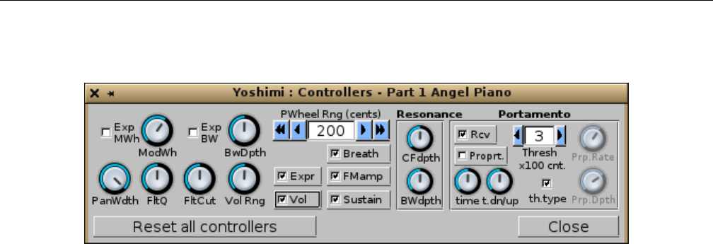
Yoshimi Software Synthesizer 9.2 Bottom Panel / Controllers
9.2 Bottom Panel / Controllers
Figure 107: Controllers Dialog
1. Exp MWh
2. ModWh
3. Exp BW
4. BwDepth
5. PanWdth
6. FltQ
7. FitCut
8. Vol Rng
9. PWheelB.Rng
10. Expr
11. Breath (1.5.6)
12. FMamp
13. Vol
14. Sustain
15. Resonance (section)
16. PortaMento (section)
17. Reset all controllers
18. Close
1. Exp MWh. Exponential Modulation Wheel. Changes the modulation scale to exponential.
Values: Off*, On
2. ModWh. Modulation Wheel Depth.
Values: 0 to 127, 80*
3. Exp BW. Exponential Bandwidth Controller. Changes the bandwidth scale to exponential.
Values: Off*, On
4. BwDepth. Bandwidth Depth.
Values: 0 to 127, 64*
5. Exp BW. Exponental Bandwidth. Changes the bandwidth scale to exponential.
Values: 0 to 127, 64*
6. PanDpth. Panning Depth.
Values: 0 to 64*
138
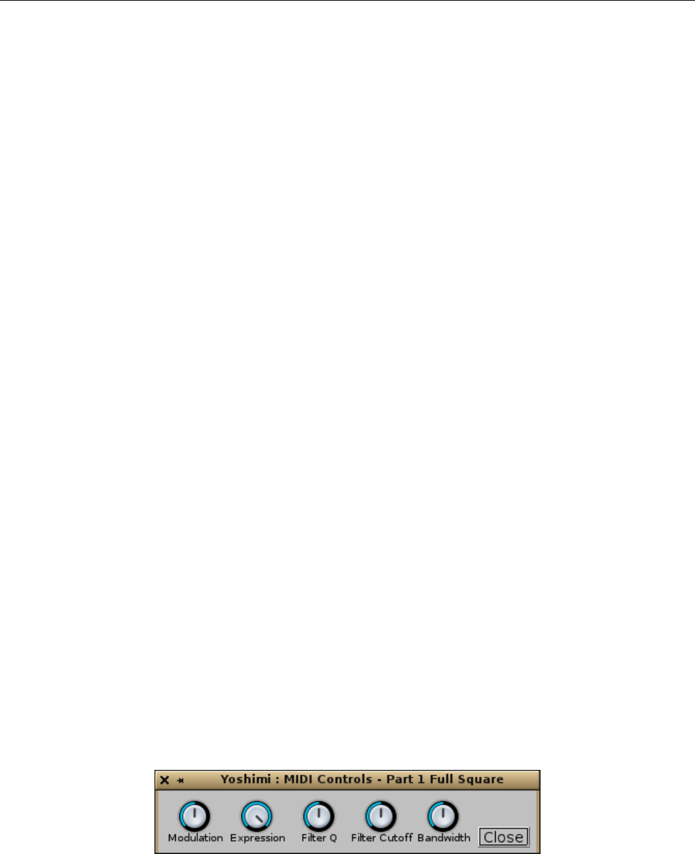
Yoshimi Software Synthesizer 9.2 Bottom Panel / Controllers
7. FltQ. Filter Q (resonance) Depth.
Values: 0 to 127, 64*
8. FltCut. Filter Cutoff Frequency Depth.
Values: 0 to 127, 64*
9. Vol Rng. Volume Range.
Values: 64 to 127, 64*
10. PWheelB.Rng. Pitch Wheel Bend Range (cents). 100 cents = 1 halftone.
Values: -6400 to 6400, 200*
11. Expr. Expression Enable. Enable/disable expression.
Values: Off, On*
12. Breath. Breath.
Breath control was once a ”per part” setting, but now it is a ”per instrument” setting. By default,
this setting is enabled. This new switch is visible from version 1.5.6 on, and it is saved only in new .xiy
format. See Section 2”Configuration Files” on page 22for details on the new format.
Values: Off, On*
13. FMamp. FM Amplitude Enable. Enable/disable receiving Modulation Amplitude controller (76).
Values: Off, On*
14. Vol. Volume Enable.
Values: Off, On*
Enable/disable receiving volume controller. Sensitivity to MIDI volume change (CC7) is now variable
in ’Controllers’ in the same way as pan width etc. The nnumeric range is 64 to 127; the default at 96 gives
the same sensitivity as before at -12dB relative to the GUI controls. 127 gives 0dB and 64 gives -26dB
15. Sustain. Sustain Pedal Enable. Enable/disable sustain pedal.
Values: Off, On*
16. Reset all controllers. Reset All Controllers.
17. Close. Close Window.
9.2.1 Bottom Panel / Controllers / MIDI Controls
There is a new, small window, accessed by right-clicking on the Controllers button on the bottom panel.
This window has five controls that are MIDI-learnable.
Figure 108: MIDI Controls from Controllers Button
1. Modulation
139

Yoshimi Software Synthesizer 9.2 Bottom Panel / Controllers
2. Expression
3. Filter Q
4. Filter Cutoff
5. Bandwidth
Will has one keyboard that sends aftertouch messages, and all of these work correctly with it. An
interesting effect was to have a sawtooth wave set up in AddSynth and the frequency LFO level turned
up. Then, he learned Modulation,Expression, and Filter Cutoff, all on aftertouch. He then reduced
their ranges in the MIDI learn window and the effect was very interesting. Try it!
Because of the way this is implemented, these controls are also accessible via CLI direct access for
both for read and write, and the knobs will respond to this, as well as to learned controls.
1. Modulation. Affects the (amplitude) modulation of all engines in the part.
2. Expression. Affects the ”expression” of all engines in the part.
3. Filter Q. Affects the sharpness of the filtering of all engines in the part.
4. Filter Cutoff. Affects the brightness of all engines in the part by increasing or reducing the corner
frequency.
5. Bandwidth. The master bandwidth control affects all engines in a part, and is real-time. It is also
highly dependent on the harmonic structure, so is most effective on SubSynth sounds. Like all of these
MIDI controls, it is a part control, not an instrument setting, and is never saved. It is available in the
window shown above, the command-line, and it is learnable. It considerably ”expands” some instruments.
9.2.2 Bottom Panel / Controllers / Resonance
1. CFdepth. Resonance Center Frequency Depth, Center Frequency Controller Depth.
Values: 0 to 127, 64*
2. BWdepth. Resonance Bandwidth Depth, Resonance Bandwidth Controller Depth.
Values: 0 to 127, 64*
9.2.3 Bottom Panel / Controllers / Portamento
1. Rcv. Portamento Receive, Receive Portamento Controllers. Determines if the part receives Porta-
mento On/Off (65) controller.
Values: Off, On*
2. Proprt. Portamento Proportional, Enable Proportional Portamento (over fixed portamento).
Values: Off*, On
3. time. Portamento time. The duration of the portamento.
Values: 0 to 127, 64*
4. t.dn/up. Portamento Time Stretch (up/down).
Values: 0 to 127, 64*
5. threshx100 cnt. Threshold of the Portamento. The minimum or maximum difference of notes in
order to do the portamento (x 100 cents). It represents the minimum or the maximum number of halftones
(or hundred cents) required to start the portamento. The difference is computed between the last note
140
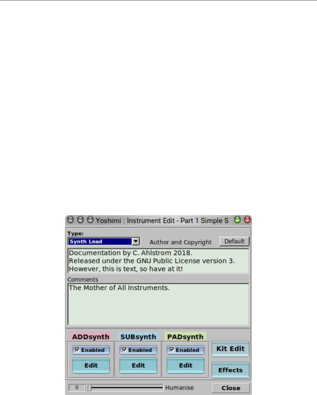
Yoshimi Software Synthesizer 9.3 Bottom Panel Instrument Edit
and current note. The threshold refers to the frequencies and not to MIDI notes (one should consider this
if one uses microtonal scales).
Values: 0 to 127, 3*
6. th.type. Threshold Type (min/max). Checked means that the portamento activates when the
difference of frequencies is above the threshold (”thresh”); not checked is for below the threshold.
Values: Off, On*
7. Propt. Proportional Portamento. If set, the portamento is proportional to ratio of frequencies.
Values: Off, On*
8. Prp.Rate. Distance required to double change from nonproportional portamento time. The ratio
needed to double the time of portamento.
Values: 0 to 127, 80*, requires Proprt. =On
9. Prp.Depth. The difference from nonproportional portamento.
Values: 0 to 127, 90*, requires Proprt. =On
9.3 Bottom Panel Instrument Edit
The main instrument-editing (”part edit”) dialog is relatively simple, and provides for editing informa-
tion that identifies the instrument, and buttons to access the more complex dialogs of the ADDsynth,
SUBsynth,PADsynth,Kit Edit, and Effects components.
Figure 109: Part Edit (Instrument) Dialog
141
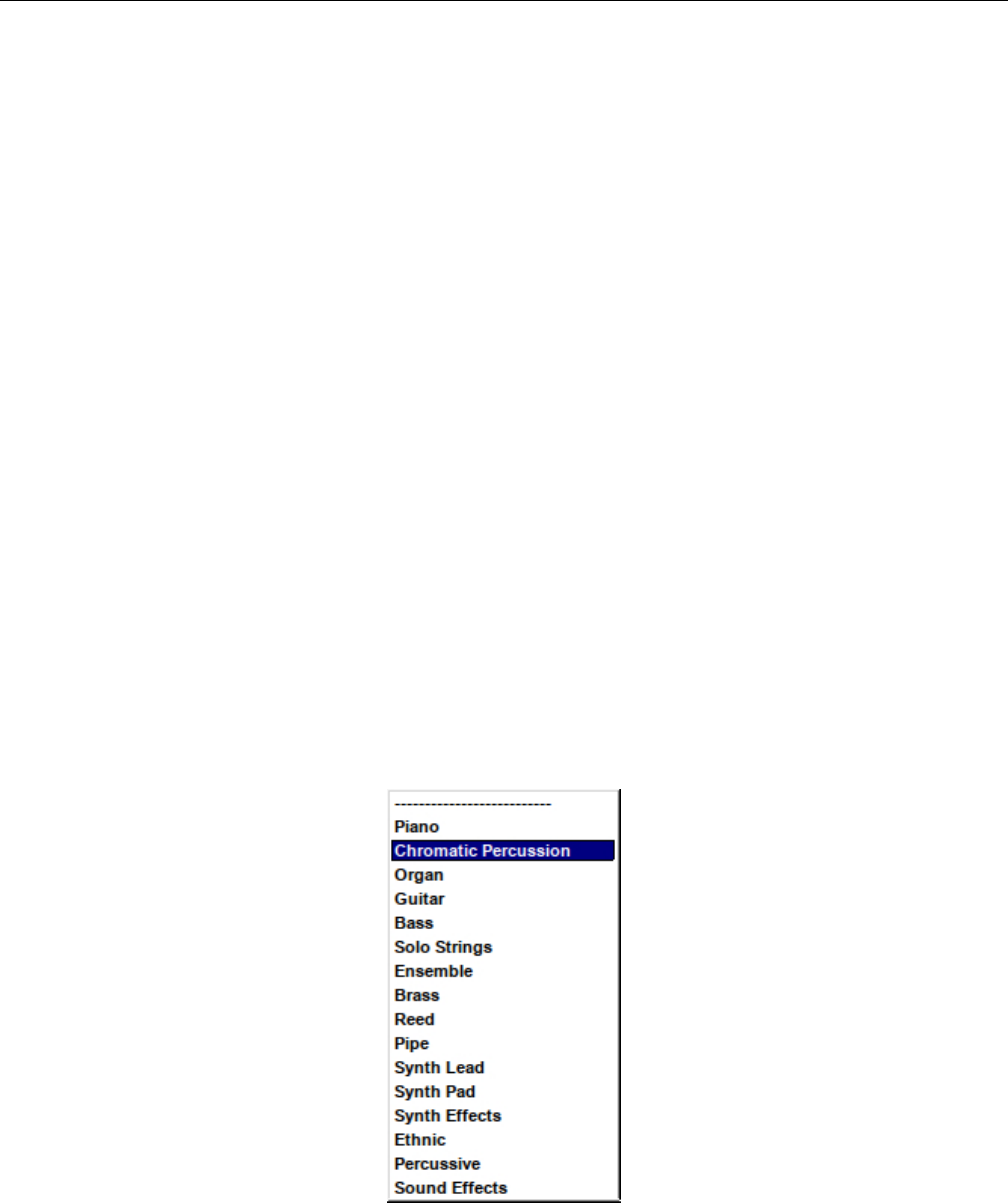
Yoshimi Software Synthesizer 9.3 Bottom Panel Instrument Edit
This dialog provides a very broad overview of the instrument, and provides access to far more detailed
dialogs to edit the instrument. This dialog is called up by the Edit button on the bottom panel of the
main Yoshimi main screen.
1. Type
2. Author and Copyright
3. Default
4. Comments
5. ADDsynth
1. Enabled
2. Edit
6. SUBsynth
1. Enabled
2. Edit
7. PADsynth
1. Enabled
2. Edit
8. Kit Edit
9. Effects
10. Rnd. Det., which is now a Humanise slider.
11. Close
The ADDsynth,SUBsynth,PADsynth,Kit Edit, and Effects dialogs are detailed in separated
sections, as they are all very complex dialogs with many sub-dialogs.
1. Type. Instrument Type. Instrument Category.
This dropdown dialog allows one to tag the type of instrument, to indicate what category of instru-
ments it fits into. The following figure shows the types.
Figure 110: Instrument Type Drop-down List
Values: Piano, Chromatic Percussion, Organ, Guitar, Bass, Solo Strings, Ensemble, Brass,
Reed, Pipe, Synth Lead, Synth Pad, Synth Effects, Ethnic, Percussive, Sound Effects
142

Yoshimi Software Synthesizer
2. Author and Copyright. This field provides space for identifying the author, copyright, and license
for the part. Starting text can be saved by using the Default button, described in the next section.
3. Default. In the main part Instrument Edit window there is a new Default button at top right.
We hope this encourages people to fill in the Author and Copyright information. To set it up, fill in the
text field as normal, then, while holding down the Ctrl key, click on the button (left or middle mouse
click) . This text will now be stored in one’s Yoshimi configuration directory, and whenever one creates a
new instrument, just click on the Default button, and the saved text will be filled in.
This button was added to discourage users from adding supplementary information directly into the
XML file.
4. Comments. Allows free-form comments and notes to be entered.
5. ADDsynth.
1. Enabled. Enables this synth type to be used in the part/instrument. When enabled, its marker
color, red, is shown.
2. Edit. Brings up the editing dialog presented in Figure 111 ”ADDsynth Edit/Global Dialog” on
page 144. There one will find a full discussion of that dialog.
6. SUBsynth.
1. Enabled. Enables this synth type to be used in the part/instrument. When enabled, its marker
color, blue, is shown.
2. Edit. Brings up the editing dialog presented in Figure 147 ”SUBsynth Edit Dialog” on page 178.
There one will find a full discussion of that dialog.
7. PADsynth.
1. Enabled. Enables this synth type to be used in the part/instrument. When enabled, its marker
color, green, is shown.
2. Edit. Brings up the editing dialog presented in Figure 125 ”PADsynth Edit Dialog” on page 163.
There one will find a full discussion of that dialog.
8. Kit Edit. Brings up the editing dialog presented in Figure 151 ”Kit Edit Dialog” on page 183.
There one will find a full discussion of that dialog.
9. Effects. Brings up the editing dialog presented in Figure 90 ”Effects Edit, No Effect” on page 114.
There one will find a full discussion of that dialog.
When the effects panels are brought up from this button, there are two extra user-interface elements:
Bypass and Close. If the Bypass item is checked, then the effect is not used; it is taken out of the
circuit.
10. Humanise (Rnd. Det.). Small Random Detune, Humanise. Sets the random detune value of the
whole part in cents. In the most recent versions of Yoshimi, this item has been replaced by a Humanise
slider. This value is an experimental feature. It lends some complexity or piquancy to the part.
Values: 0* to 50
11. Close. Closes the Edit window.
10 ADDsynth
The Yoshimi ADDsynth (also spelled ”ADsynth” or ”AddSynth”) dialog is a complex dialog for creating
an instrument. This is the most complex, most advanced and most sophisticated part of the synthesizer
and allows one to edit the parameters that apply to all the voices of ADDsynth.
143
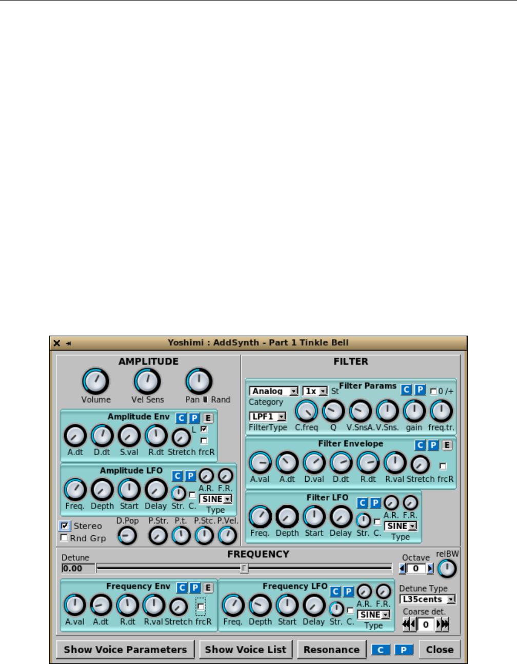
Yoshimi Software Synthesizer
ADDsynth, a primarily additive synthesis engine, is one of the three major synthesis engines available
in Yoshimi/ZynAddSubFX. The basic concept of this engine is the summation of a collection of voices,
each of which consists of oscillators.
”ADDsynth” (sometimes spelled ”ADsynth”) or ”ADnote” is a complex engine which makes sounds
by adding a number of voices. Each one has filters, envelopes, LFOs, morphing, modulation, resonance,
etc. Each voice includes a very powerful waveform generator with up to 128 sine/non-sine harmonics.
One can use Fourier synthesis, or if one doesn’t like it, one can use wave-shaping/filtering of functions.
This engine includes anti-aliasing. Modulation includes ring modulation, phase modulation, and more.
The modulators can have any shape. [27]
There are two oscillators per voice: the voice oscillator and the modulation oscillator. For the voice
oscillator, one can use one defined for that voice (internal) or link to the oscillator of any lower-numbered
voice. For the modulation oscillator one can have a locally defined one (internal) or one can have two
alternatives: either the modulation oscillator from a lower-numbered voice, or the oscillator from the
lower-numbered voice itself (that voice must be enabled).
In the voice window, the Oscillator Source gives the choice of previous voice oscillators and the
Local Oscillator gives you the choice of previous modulation oscillators and the current (internal)
oscillator.
The sum of the voices are passed through filters and amplification to produce the final sound. This
could lead one to think that ADDsynth is just a bunch of minor post-processing, and at this level much
of the sound generation is hidden.
Figure 111: ADDsynth Edit/Global Dialog
144

Yoshimi Software Synthesizer 10.1 ADDsynth / AMPLITUDE
The major sections of this dialog are listed:
1. AMPLITIUDE (stock section)
2. FILTER (stock section)
3. FREQUENCY (stock section)
4. Show Voice Parameters (section)
5. Show Voice List (section)
6. Resonance (stock section)
7. C
8. P
9. Close
This complex dialog is best described section by section. Many of the sub-sections are stock sub-panels
described elsewhere in this document. References to those sections are included.
One thing to note is that the small Red reset button next to the Pan knob is no longer present.
Instead, one can use a right-click on this knob to reset it to its home position and value.
10.1 ADDsynth / AMPLITUDE
1. Volume
2. Vel Sens
3. Pan
4. Rand
5. Amplitude Env The Amplitude Env panel is described in detail in Section 6.5.1 ”Amplitude
Envelope Sub-Panel” on page 89.
6. Amplitude LFO The Amplitude LFO panel is described in detail in Section 6.4.5 ”LFO User
Interface Panels” on page 85.
7. Stereo
8. Rnd Grp
9. P.Str.
10. P.t
11. P.Stc.
12. P.Vel.
Note the two sub-panels, mentioned above, that are described elsewhere. They will not be discussed
in detail below.
1. Volume. ADDsynth Volume. Sets the overall/relative volume of the instrument.
Values: 1 to 127, 64*
2. Vel Sens. ADDsynth Velocity Sensing function. Velocity sensing is simply an exponental transforma-
tion from the note’s velocity to some parameter change. Observe Figure 112 ”Velocity Sensing Function”
on page 146. It shows how the velocity sensing controls affects the translation of a parameter over the
whole range of possible note velocities. Turn the knob rightmost/maximum to disable this function.
Values: 1 to 127, 64*
145
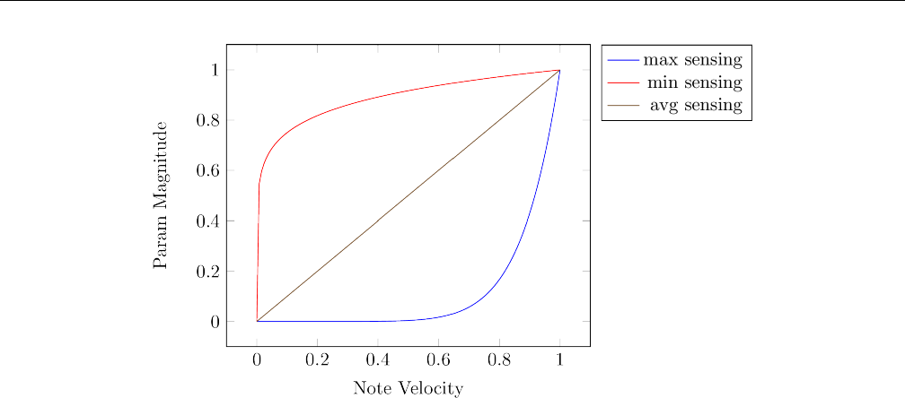
Yoshimi Software Synthesizer 10.1 ADDsynth / AMPLITUDE
Figure 112: Velocity Sensing Function
3. Pan. ADDsynth Global Panning. Dialing the knob to leftmost or zero gives random panning. Also,
clicking on the Rand LED will enable random panning.
Values: 0, 1 to 127, 64*
4. Rand. ADDsynth Random Panning Indicator. A red fill-in color provides an indicator for the
activation of random panning in this control. Also, clicking on this small control will enable random
panning.
Next, we skip the Amplitude Env and Amplitude LFO panels, which are described elsewhere,
as noted above.
5. Stereo. ADDsynth Stereo. Stereo can be enabled. When disabled, all the voices will also have
panning disabled.
Values: Off, On*
6. Rnd Grp. ADDsynth Random Group. Disable harmonic amplitude randomness of voices with a
common oscllator.
Values: Off*, On
7. P.Str. ADDsynth Punch Strength. The punch strength of a note in ADDsynth is a constant
amplification to the output at the start of the note, with its length determined by the punch time and
stretch and the amplitude being determined by the punch strength and velocity sensing. The relBW
control in the frequency panel is effectively a multiplier for detuning all voices within an ADnote.
Values: 0* to 127
8. P.t. ADDsynth Punch Time (duration). Sets the punch effect duration (from 0.1 ms to 100 ms on
an A note, 440Hz).
Values: 0 to 127, 64*
9. P.Stc. ADDsynth Punch Stretch. Sets the punch effect stretch according to frequency. On lower-
frequency notes, punch stretch makes the punch effect last longer.
Values: 0 to 127, 64*
146

Yoshimi Software Synthesizer 10.2 ADDsynth / FILTER
10. P.Vel. ADDsynth Punch Velocity Sensing. The higher this value, the higher the effect of velocity
on the punch of the note.
Values: 0 to 127, 72*
10.2 ADDsynth / FILTER
The ADDsynth FILTER block consists solely of sub-panels described in detail in the sections noted below.
The sub-panels of the FILTER section are:
1. Filter Params
2. Filter Env
3. Filter LFO
1. Filter Params. ADDsynth Filter Parameters. The Filter Params panel is described in detail in
Section 6.2.5 ”Filter Parameters User Interface” on page 78.
2. Filter Env. ADDsynth Filter Envelope. The Filter Env panel is described in detail in Section 6.5.5
”Envelope Settings for Filter” on page 94.
3. Filter LFO. The Filter LFO panel is described in detail in Section 6.4.5 ”LFO User Interface
Panels” on page 85.
10.3 ADDsynth / FREQUENCY
1. Detune
2. FREQUENCY slider
3. Octave
4. RelBW
5. Frequency Env. A stock sub-panel described in Section 6.5.4 ”Envelope Settings, Frequency” on
page 93.
6. Frequency LFO A stock sub-panel described in Section 6.4.7 ”Frequency LFO Sub-panel” on
page 88.
7. Detune Type
8. Coarse det.
1. Detune. ADDsynth Detune Value. This display box shows the value of the detune as selected by
the frequency slider described below.
Figure 113: ADDsynth Frequency Detune Type
This value defines the number of cents that define the range of the FREQUENCY slider, that is 35
cents, 10 cents, 100 cents (one semitone), or 1200 cents (1 octave), below and above the main frequency.
The default is 35 cents. The 1200-cents setting provides a whole octave of detuning in either direction.
The ”L” stands for ”linear”, and the ”E” for ”exponential”, to describe how the detune slider acts.
147

Yoshimi Software Synthesizer 10.4 ADDsynth / Voice Parameters
Values: Default*, L35cents, L10cents, E100cents, E1200cents
2. FREQUENCY slider. ADDsynth Fine Detune (cents), a slider control. While the detune type
dropdown and the octave selection provide a coarse selection of detune, the slider allows for a finer
selection of detune, up to roughly one-third of a semitone.
Values: -35.00 to 35.00,-10.00 to 10.00,-100.00 to 100.00,-1200.00 to 1200.00
3. Octave. ADDSynth Octave. The octave setting changes the frequency by octaves.
Values: -8 to 7, 0*
4. RelBW. ADDSynth Relative Bandwidth. Bandwidth: how the relative fine detune of the voice is
changed.
Values: 0 to 127, 64*
5. Frequency Env. ADDsynth Frequency Envelope. The Frequency Env panel is described in detail
in Section 6.5.4 ”Envelope Settings, Frequency” on page 93.
6. Frequency LFO. The Frequency LFO panel is described in detail in Section 6.4.5 ”LFO User
Interface Panels” on page 85
7. Detune Type. Frequency Detune Type. This setting provides a coarse detuning. We would welcome
an explanation of exactly is meant by the numbers and the ”E” versus ”L” designation.
Values: L35cents, L10cents, E100cents, E1200cents
8. Coarse det. Coarse Detune, ”C.detune”. The one-arrow buttons change the value by one. The
two-arrow buttons change the value by ten. Again, we need a way to explain the interactions of the slider,
the octave setting, the detune type, and the coarse detune settings.
Values: -64 to 63, 0*
9. Show Voice Parameters. ADDsynth Show Voice Parameters. This button brings up the ”voice
parameters” dialog discussed in the next section.
10.4 ADDsynth / Voice Parameters
Again, this dialog is built from some stock sections and stock sub-panels, plus additional elements.
Each Yoshimi ADDsynth instrument consists of up to 8 voices. This dialog provides a way to define
each of the 8 voices in great detail. By default, an ADDsynth instrument consists of one voice, voice 1.
148
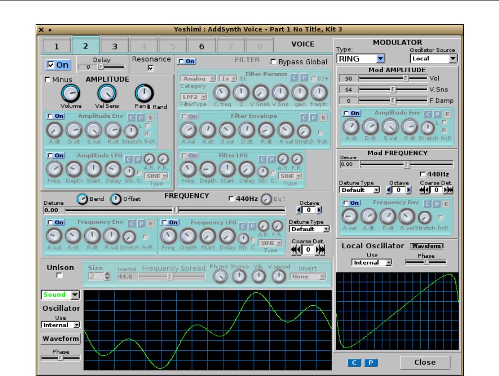
Yoshimi Software Synthesizer 10.4 ADDsynth / Voice Parameters
Figure 114: ADDsynth Voice Parameters Dialog
Note the 8 VOICE tabs at the top of the window. These make it easy to switch to another voice, and
without opening up yet another editing window. Non-active voices are shown with an inactive tab/number
appearance. This is all in synchrony with the Voice List window.
Also note that there is no longer a Red reset button next to the Pan knob; use a right-click on this
knob to reset it.
This dialog consists of a few extra settings, plus a number of stock dialog sections. Take some time to
compare Figure 111 ”ADDsynth Edit/Global Dialog” on page 144, which covers the overall instrument,
with Figure 114 ”ADDsynth Voice Parameters Dialog” on page 149, which covers each of the voices. The
stock sections in the former cover the whole instrument as one, while the very similar stock sections in the
latter cover only the voice they configure. Obviously, the combinations of settings are essentially endless.
Each voice can be amplitude-controlled, filter-controlled, and frequency-controlled. Each voice can
also be modulated by an internal modulator. Another property of the voice is that one can tell Yoshimi
to modulate a given voice with any of the voices that are numbered less than that voice.
1. Voice Number Tab
2. On
3. Delay
4. Resonance
149

Yoshimi Software Synthesizer 10.4 ADDsynth / Voice Parameters
5. AMPLITUDE (see the stock-panel section below)
6. FILTER (see the stock-panel section below)
7. MODULATOR (see the stock-panel section below)
8. FREQUENCY (see the stock-panel section below)
1. Voice Number Tab. ADDsynth Voice Number. When highlighted this indicates the voice currently
being viewed. Each Yoshimi part/instrument can consist of up to eight voices. The voice being worked
on can be selected using the Current Voice tab.
Values: 1* to 8
2. On. ADDsynth Voice On/Off. Enables this voice in the part/instrument.
Values: Off, On
3. Delay. ADDsynth Voice Delay.
Values: 0* to 4.90
4. Resonance. ADDsynth Voice Resonance On/Off. The rest of the GUI elements (AMPLITUDE,
FILTER, MODULATOR, FREQUENCY, and Voice Oscillator) are more detailed, and discussed in the
sections that follow.
Values: Off, On*
10.4.1 ADDsynth / Voice Parameters / AMPLITUDE
This section of the voice parameters dialog also includes a couple of stock sub-panels that have an
additional ”Enable” control.
1. Minus
2. Volume
3. Vel Sens
4. Pan
5. Pan randomness indicator
6. Pan reset (red button)
7. Amplitude Env, Stock + Enable
8. Amplitude LFO, Stock + Enable
1. Minus. ADDsynth Amplitude Minus. When checked, this control inverts the phase of the waveform
relative to all the other voices. With only one voice enabled, this control will seem to do nothing. With
two voices enabled with identical waveforms, the Minus control will indeed seem to reverse the effect
of the volume control. But if the waveforms are different, then it can provide some interesting harmonic
change effects.
Values: Off*, On
2. Volume. ADDsynth Voice Volume. Sets the (relative) volume of this voice in the part/instrument.
Values: 0 to 127, 100
3. Vel Sens. ADDsynth Voice velocity-sensing function; setting to rightmost/max disables this function.
Values: 0 to 127*
4. Pan. ADDsynth Voice panning; setting to leftmost/0 gives random panning.
Values: 0 to 127, 64*
150

Yoshimi Software Synthesizer 10.4 ADDsynth / Voice Parameters
5. Pan randomness indicator. ADDsynth Voice random panning On/Off. Fills in red to indicate
that random panning is in force. Clicking on it will also set random panning.
6. Amplitude Env, Stock + Enable. ADDsynth Amplitude Envelope Sub-panel. See Section 6.5.1
”Amplitude Envelope Sub-Panel” on page 89. Additionally, the Enable checkbox allows the enabling of
this component.
7. Amplitude LFO, Stock + Enable. ADDsynth Amplitude LFO Sub-panel. See Section 6.4.5
”LFO User Interface Panels” on page 85. Additionally, the Enable checkbox allows the enabling of this
component.
10.4.2 ADDsynth / Voice Parameters / FILTER
This section of the voice parameters dialog also includes a couple of stock sub-panels that have an
additional ”Enable” control.
1. Enable
2. Bypass Global F.
3. Filter Params, Stock
4. Filter Env, Stock + Enable
5. Filter LFO, Stock + Enable
1. Enable. ADDsynth Voice Enable Filter. This value enables the whole FILTER dialog section.
Values: Off*, On
2. Bypass Global F. ADDsynth Voice Bypass Global Filter. The voice signal bypasses the global
filter.
Values: Off*, On
We need to make sure there is a discussion of the global filter.
3. Filter Params, Stock. See Section 6.2.5 ”Filter Parameters User Interface” on page 78.
4. Filter Env, Stock + Enable. See Section 6.5.5 ”Envelope Settings for Filter” on page 94.
5. Filter LFO, Stock + Enable. See Section 6.4.6 ”Filter LFO Sub-panel” on page 87.
10.4.3 ADDsynth / Voice Parameters / FREQUENCY
This frequency section is almost a stock part. It is similar to the ADDsynth Edit’s FREQUENCY
section.
1. Detune
2. FREQUENCY slider
3. 440Hz
4. Eq.T
5. Octave
6. Detune Type
7. Coarse det
8. Frequency Env, Stock + Enable
9. Frequency LFO, Stock + Enable
10. Voice Oscillator
151
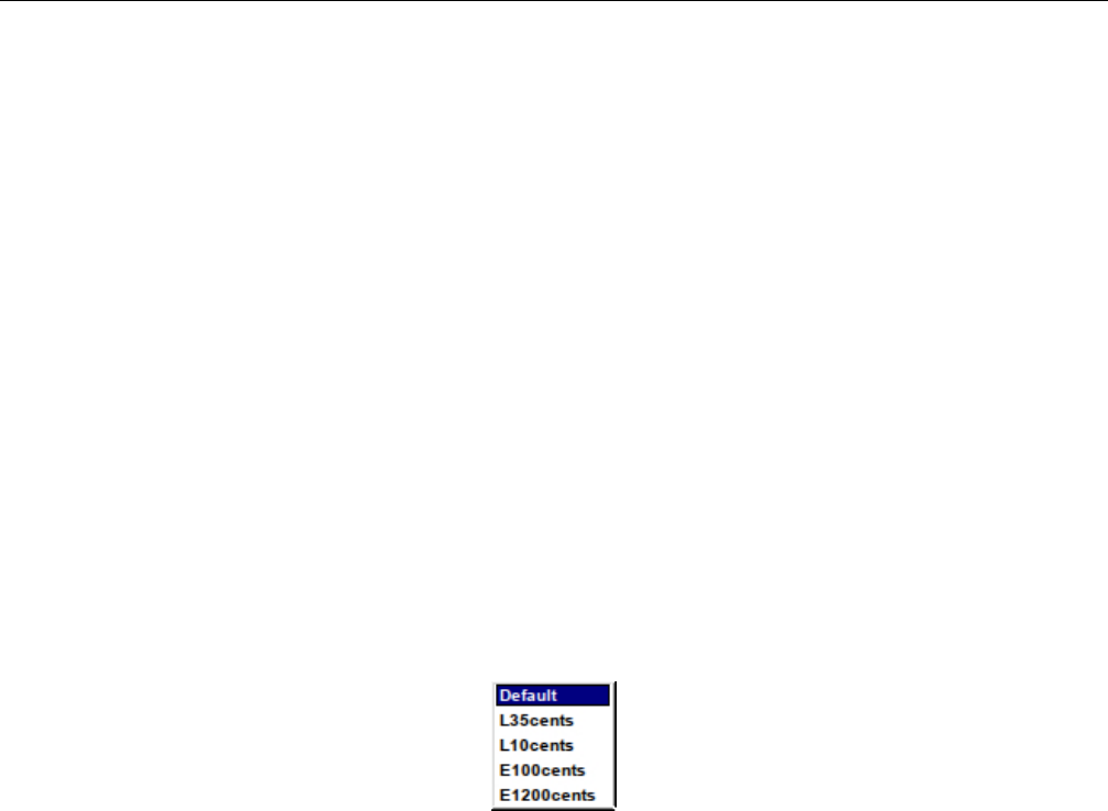
Yoshimi Software Synthesizer 10.4 ADDsynth / Voice Parameters
1. Detune. Voice Parameters Detune. Shows the value selected by the frequency slider.
2. FREQUENCY slider. Frequency Slider. Provides fine detune, in cents. Note that 35 cents is
roughly one-third of a semitone.
Values: -35.00 to 35.00, 0*
3. 440Hz. 440 Hz Selection. Fixes the voice base frequency to 440 Hz. One can adjust this with the
detune settings. No matter what key is played on the keyboard, this voice will emit only 440 Hz. This
is useful for defining a constant frequency to use as a modulator for the other voices in the part. For
example, one can define voice 1 to be a tone, then define voice 2 to be 440 Hz. The two voices will mix,
but only voice 1 will change frequencies as different keys are played.
Values: Off*, On
4. Eq.T. Equal Temperament? This item is enabled only if the 440Hz check-box is enabled. It
determines how the frequency varies according to the keyboard. If set to its leftmost (0) value, then the
frequency is fixed.
Values: 0 to 127?
5. Octave. Voice Parameters Octave.
Values: -8 to 7, 0*
6. Detune Type. Detune Type.
Figure 115: Frequency Detune Type
Values: Default*, L35cents, L10cents, E100cents, E1200cents
7. Coarse det. Coarse Detune. Is this setting in units of semitones?
Values: -64 to 63, 0*
8. Frequency Env, Stock + Enable. Frequency Envelope. See Section 6.5.4 ”Envelope Settings,
Frequency” on page 93.
9. Frequency LFO, Stock + Enable. Frequency LFO. See Section 6.4.7 ”Frequency LFO Sub-panel”
on page 88.
10. Voice Oscillator. Voice Parameters Oscillator. See the next section.
10.4.4 ADDsynth / Voice Parameters / UNISON
Enabling this item causes the Unison-related items to become activated.
1. Enable (unmarked button)
2. Size
3. Frequency Spread
4. Ph.rnd
5. Stereo
152
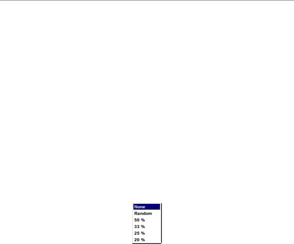
Yoshimi Software Synthesizer 10.4 ADDsynth / Voice Parameters
6. Vibrato
7. V.speed
8. Invert
1. Enable. Enables or disables unison.
Values: Off*, On
2. Unison Size. Sets the number of unison sub-voices.
Values: 2* to 50
3. Unison Frequency Spread. Frequency spread of the unison (cents).
Values: 0 to 200, 44.6*
4. Phase Randomness. Unison Phase Randomness.
Values: 0 to 127*
5. Stereo Spread. Unison Stereo Spread.
Values: 0 to 127, 64*
6. Unison Vibrato. Unison Vibrato.
Values: 0 to 127, 64*
7. Vibrato Speed. Unison Vibrato Average Speed.
Values: 0 to 127, 64*
8. Phase Invert. Unison Phase Invert. Values: None*, Random, 50%, 33%, 25%, 20%
Figure 116: Unison Phase Invert Dropdown
10.4.5 ADDsynth / Voice Parameters / Voice Oscillator
The ADDsynth Voice Oscillator panel is tucked in the lower left side of the ADDSynth Voice Parameters
editor.
1. Sound
2. Waveform graph
3. Use
4. Waveform (was Change)
5. Phase
6. C
7. P
8. Close Window
1. Sound. ADDSynth Oscillator Type (sound/noise). Sound/Noise choice. Select the mode of the
oscillator (sound versus white noise).
Values: Sound*, Noise (white), Noise (pink)
153
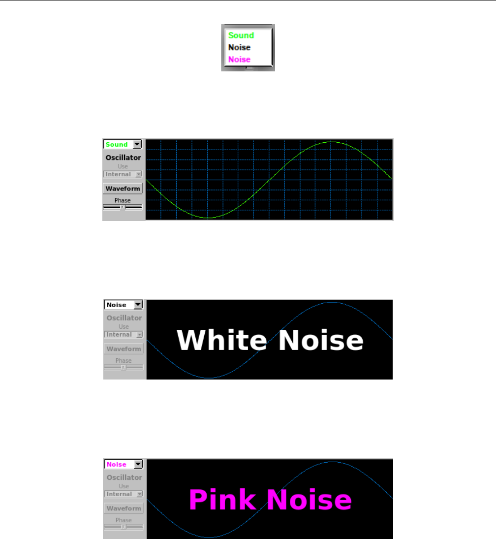
Yoshimi Software Synthesizer 10.4 ADDsynth / Voice Parameters
Figure 117: Voice Oscillator Choices
2. Waveform graph. Waveform Graph. Shows a period of the currently configured oscillator.
Figure 118: Oscillator in ADDSynth Voice
If white Noise is selected, then the waveform graph simply announces ”White Noise”. Also, the
Unison control is disabled.
Figure 119: White Noise in ADDSynth Voice
If pink Noise is selected, then the waveform graph simply announces ”Pink Noise”. Also, the Unison
control is disabled.
Figure 120: Pink Noise in ADDSynth Voice
3. Use (oscillator). Use Oscillator. If the Current Voice is set to a value greater than 1, meaning
that one is editing additional voices, then this dropdown item also includes the values of all oscillators
less then this one, marked as ”Voice n”, where ”n” is the voice number. For example, if one is currently
editing current voice 3, then the dropdown list includes Internal,Voice 1, and Voice 2.
Values: Internal*, Other oscillators ("Voice n")
154
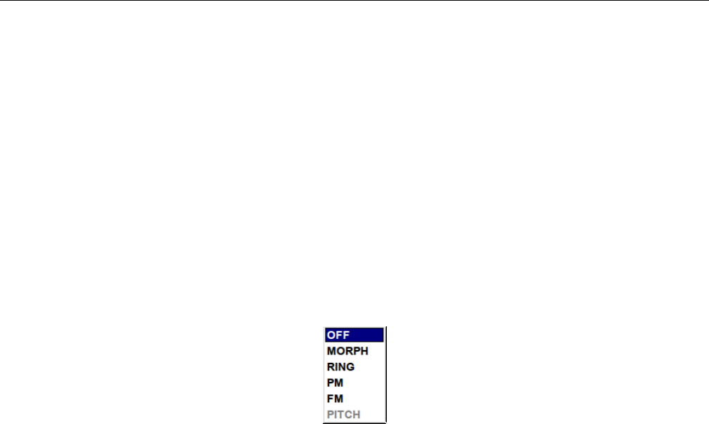
Yoshimi Software Synthesizer 10.4 ADDsynth / Voice Parameters
4. Waveform. ADDSynth Voice Oscillator Waveform. This button brings up the ADDsynth Oscillator
Editor dialog. This dialog is described elsewhere; it used to be called Change.
5. Phase. Voice Oscillator Phase.
Values: 0 to 360 (0 to 2*pi)
10.4.6 ADDsynth / Voice Parameters / MODULATOR
1. Type:
2. Oscillator Source
3. Mod AMPLITUDE
4. Mod FREQUENCY
5. Local Oscillator
1. Type:. ADDsynth Modulator Type.
Figure 121: Voice Modulator Type
1. OFF. This setting turns off the modulator.
2. MORPH The morph modulator works by combining the output of the voice oscillator and the
modulator opscillator into one sonud, with the amplitude envelope translating between one waveform
and the other. It is important that the amplitude envelope is enabled, otherwise no change will take
place.
3. RING The ring modulator is useful for making bell-like sounds and some weird effects. The ring
modulator works by multiplying two waveforms together, producing a signal that possesses the sum
and difference of the frequencies present in the waveforms. The ins-and-outs of the ring modulator
are explained in detail in paragraph 10.4.6.1 ”Tip: Using the Ring Modulator” on page 157.
4. PM The PM (phase modulation) modulator works by using a modulator envelope to change the
pulse of the voice oscillator. It produces a similar effect to frequency modulation. Generally, set
F.Damp to zero, so that the modulation amount doesn’t depend on the note number.
5. FM The (frequency modulation) morph modulator works by modulating the frequency. Examples
can be heard in the ”Ethereal” and ”Steel Wire” instruments.
6. PWM The pulse width modulator works by pulse-width modulation.
Values: OFF, MORPH, RING, PM, FM, PWM
2. Modulator Source. AddSynth Modulator Source. This feature allows one of the voices (of the
up to 8 allowed in a single ADDsynth instrument) to be used as a modulator or external oscillator for
another voice in the instrument. Note that the voice must be one with a number below the current voice.
It’s important to understand that oscillators always exist even if not used. This option specifies to use
the oscillator of another voice or the local oscillator.
The parameters must be lower than the voice index; one cannot use the oscillator from a voice with a
bigger index (e.g. one can’t use the oscillator of voice 8 for voice 4). This is very useful because, if one uses
155

Yoshimi Software Synthesizer 10.4 ADDsynth / Voice Parameters
many voices with the same oscillator settings, one can use only one oscillator and select other voices to
use this, and if one changes a parameter of this oscillator, all voices using this oscillator will be affected.
If one sets up voice 2 as a square wave, and voice 1 as a triangle wave, then sets voice 3 to voice 2,
voice 3 will get a square wave.
If one then sets voice 2 to voice 1, voice 2 will get a triangle wave but voice 3 will still get a square
wave.
Voice 3 can use the oscillator from voice 1, even if voice 1 is switched off.
Modulator 3 can use the oscillator from modulator 1, even if modulator 1 is switched off, but modu-
lator 3 can’t use voice 1 if voice 1 is switched off.
However, if voice 2 is using the oscillator from voice 1, and modulator 3 is using voice 2, it will still
get voice 2 oscillator.
When a voice or modulator is pointed to another voice/modulator, the oscillator window will show
the waveform of the actual source, and all the controls will change this, not the internal oscillator.
Local. Uses the local (internal) oscillator as the modulator of another voice.
Values: Local*, Other voice numbers
Oscillator Source. Use another voice as a modulator instead of the modulator of the internal voice.
One can make a ”modulation stack”. The modulator of the voice itself is disabled. One can only select
Local (i.e. Internal), or one from a lower numbered voice.
Values: Local*, "Mod n"
3. Mod AMPLITUDE. Modulator Amplitude.
1. Vol Volume. Values: 0 to 127, 90*
2. V.Sns Velocity Sensing Function; set to rightmost/max to disable. Values: 0 to 127, 64*
3. F.Damp Modulator Damp at higher frequency. How the modulator intensity is lowered according
to lower/higher note frequencies. Values: 0 to 127, 90*
4. Amplitude Env, Stock + Enable See Section 6.5.1 ”Amplitude Envelope Sub-Panel” on page 89.
4. Mod FREQUENCY. Modulator Frequency.
1. Detune slider Fine Detune (cents). Values: -35.00 to 35.00, 0*
2. Detune Type Fine Detune (cents). Values: L35cents, L10cents, E100cents, E1200cents See
Figure 113 ”ADDsynth Frequency Detune Type” on page 147.
3. Octave Octave. Values: -8 to 7, 0*
4. Coarse Det. Coarse Detune. Values: -64 to 63, 0*
5. Filter Env, Stock + Enable See Section 6.5.5 ”Envelope Settings for Filter” on page 94.
5. Local Oscillator. Local Oscillator. Provides the modulator for the oscillator. This value must
indicate a modulator from a voice with a number less than the current voice. Entries are greyed out for
Voice 1, as there is no lower-numbered voice available for modulation.
Values: Internal*, "Mod n"
1. Waveform ADDsynth Oscillator Editor.
2. Use Oscillator to Use. See the paragraph below. Values: Internal*, Other oscillators?
3. Phase Oscillator Phase. Values: 0 to 360 (0 to 2PI)
4. Waveform graph Waveform graph.
156

Yoshimi Software Synthesizer 10.5 ADDsynth / Voice List
One has the choice between Internal, which in this case means a completely independent modulator
oscillator per voice (extra waveform button), or Mod. (n), which refers to the modulation oscillators one
has already defined for the voices with a lower index. The voice of lower index doesn’t need to be enabled
in order to be used as a modulator. This means one can make one modulation oscillator for voice 1, and
reuse it in voices 2 and 3. This is the same system used for the normal (voice) oscillators.
10.4.6.1 Tip: Using the Ring Modulator
This section is derived from one of the short text files in the Yoshimi source-code bundle ([19] or [20]). It
notes that ”Some people have been confused about how to use an ’external’ Mod Oscillator”, and provides
usage notes that we will elaborate on here. Here is the way to use the ring modulator:
1. Open the ADDsynth editing window. Then open Show Voice Parameters.
2. For Type, select the RING value. This selection will activate the Mod Oscillator.
3. In the Local Oscillator, click on Waveform to open the ADDsynth Oscillator Editor.
4. Set the wave-shape to Triangle.
5. Switch to voice number 2 and enable it.
6. Again, for Type, select the RING value. However, feel free to select one of the other modulators,
if one wishes.
7. One can now use Internal for voice 2, or select Voice 1, to use the first voice as in internal
modulator.
8. Change the internal voice to, for example, Square.
9. Do the same setup for voice 3. One will find that one can use its Internal or either of the two
previous ones.
Now the joker in the pack is that one can disable both the previous voices but still use their Mod
Oscillators.
In a newsgroup ([14], the following note is found.
Say I want the A tone ring-modulated by 880Hz. A is 440 Hz, the ring modulation setting lets me choose
the modulation frequency relative to the frequency of the tone. So I choose octave 1 and let the detune at zero.
If I move the detune, it’ll shift the modulation frequency a bit, which will make a disharmonic effect.
Wet/dry setting is controlled by volume in ”modulation amplitude”. The modulation frequency can further
be multiplied or several modulations can be simulated by changing the oscillator waveform.
One huge letdown is that it is only available for Adsynth. PadSynth does not seem to have ring modulation
option, so the coolest sounds stay out of question for massive lead tones. :-(
We have provided a more useful ”tutorial” on using the ring modulator in the Yoshimi Cookbook [4]
document.
Finally, at the bottom of the ADDsynth Voice Part dialog, (under the Modulator section, we find
the last few controls.
1. C. Copy D note parameters (”DnoteParameters”).
2. P. Paste D note parameters (”DnoteParameters”).
3. Close Window. Close.
10.5 ADDsynth / Voice List
The ADDsynth Voices List shows a summary of voices 1 to 8, and allows some overall control of them,
almost like a simple mixer. It is brought on-screen via the Show Voice List button of the ADDsynth
global part editor. It is fully in sync with the voice windows.
157
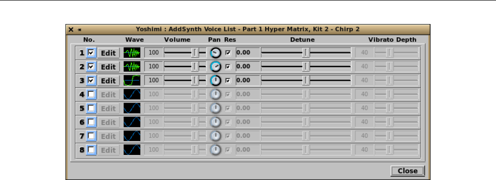
Yoshimi Software Synthesizer 10.5 ADDsynth / Voice List
Figure 122: ADDsynth Voices List
1. No. (1 to 8)
2. Edit
3. Wave
4. Vol
5. Pan
6. Res
7. Detune
8. Vibrato Depth
9. Hide Voice List
1. No. (1 to 8). Voice List Number. This check-box enables or disables a given voice in the current
part.
Values: Off, On
2. Edit. ADDSynth Voice List Edit Button. This button brings up the appropriate ADDSynth Voice
dialog so that the waveform can be easily brought up for modification.
3. Wave Icon. Waveform Icon. The waveform icon shows a rough rendering of the actual shape of the
voice waveform, or the letter Nis the voice is constructed from white noise. Note that this picture isn’t
updated if the voice is edited, until the voice list is closed and reopened.
4. Vol. Voice Volume. This slider controls the relative volume of a given voice in the current part.
Values: 0 to 127, 100*
5. Pan. Voice Panning (0/leftmost is Random). This slider controls the panning of a given voice in the
current part.
Values: 0 to 127, 64*
6. Res. Resonance On/Off. Enable/disable the resonance effect of a voice. Note that the resonance
is configured in by the Resonance dialog brought up by the Resonance button at the bottom of the
ADDsynth main dialog. The resonance dialog has its own Enable button, as well. This is provided so
individual voices can bypass the resonance filter.
Values: Off, On*
7. Detune Value. This read-only text-box shows the current value of detune as selected by its slider.
8. Detune. Fine Detune (cents).
158
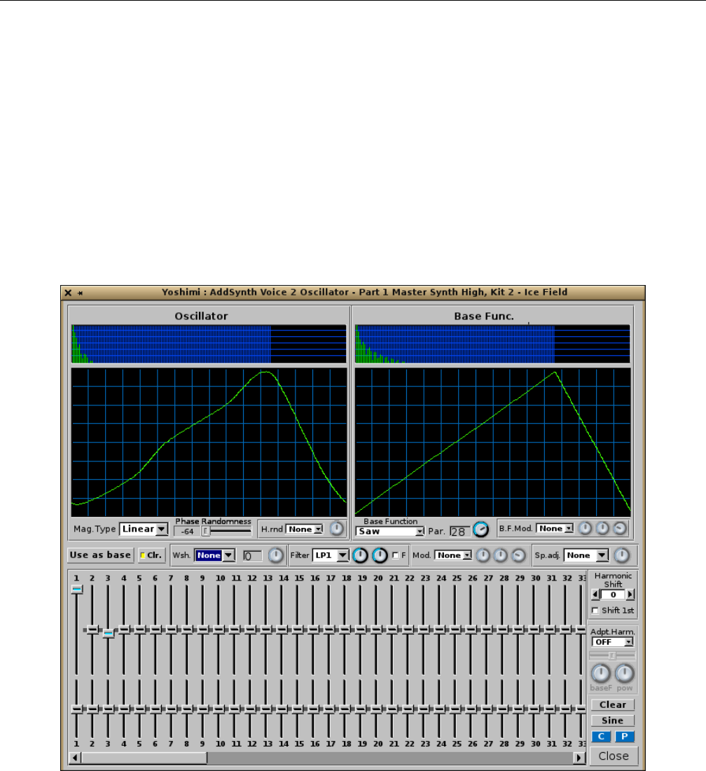
Yoshimi Software Synthesizer 10.6 ADDsynth / Oscillator
Values: -35 to 35, 0*
9. Vibrato Depth. Frequency LFO Amount/Depth. This setting can be very useful because, with the
detune settings, one can create very good sounding instruments.
Values: 0 to 127, 40*
10. Hide Voice List. Hide Voice List. A Close button, really, and that is what it is in the latest
version of Yoshimi.
10.6 ADDsynth / Oscillator
Pressing the Waveform button in the ADDsynth voice-editor dialog brings up a very complex dialog for
modifying the harmonics of the voice.
Figure 123: ADDsynth Oscillator Editor
This item is nearly identical to the PADsynth harmonic editor depicted in Figure 138 ”Harmonic
Content Editor” on page 170, except for the items noted below. Obviously, it is a topic unto itself!
1. Oscillator Spectrum Graph
2. Oscillator Waveform Graph
3. Mag.Type
4. Phase Randomness (ADDsynth Oscillator Editor only)
159
Yoshimi Software Synthesizer 10.7 ADDsynth / Resonance
5. H.rnd (ADDsynth Oscillator Editor only)
6. H.rnd knob (ADDsynth Oscillator Editor only)
1. Oscillator Spectrum Graph. Oscillator Spectrum Graph. This graph shows the spectrum of the
oscillator as a series of vertical lines, a kind of frequency histogram.
2. Oscillator Waveform Graph. Oscillator Waveform Graph. This graph shows the temporal wave-
form of the oscillator.
3. Mag.Type. Oscillator Magnitude Type. Sets how the magnitudes from the user interface behave.
See the values below.
4. Phase Randomness. Phase Randomness. Sets the randomness of the oscillator phase which is
settable from -64 (-90 deg) to 63 (+90 deg).
5. H.rnd. Harmonic Amplitude Randomness. Enables the feature and sets the ’law’ for the way
randomness is applied.
Figure 124: ADDsynth Oscillator Harmonic Randomness Selections
Values: None, Pow, and Sin
6. H.rnd knob. Harmonic Amplitude Randomness Knob. Adjusts the amount of randomness applied
to the amplitudes of individual harmonics.
Values: 0 to 127, 64*
10.7 ADDsynth / Resonance
This dialog, shared in common with the PADsynth editor, is a stock user-interface element described in
Section 6.3 ”Stock Resonance Settings” on page 80.
11 PADsynth
The Yoshimi PADsynth dialog is a complex dialog for creating a pad instrument, ”PADsynth” or ”PAD-
note” is engine that makes very beautiful pads and other instruments. (These instruments can be exported
for use with other programs too).
The PADsynth dialog consists of two major tabs, Harmonic Structure and EnvelopesLFOs.
Each of these tabs is complex, so the discussion will break the tabs down by sub-sections.
There is extra protection for a really huge PadSynth engine (that can potentially take tens of seconds
to complete). For that time, any attempt to alter the part that contains the one that’s updating will not
accept any other changes, and will give the warning: Part nbusy.
11.1 PADsynth / Algorithm
The complexity of the PADsynth dailog merely reflects the complexity of the PADsynth algorithms.
160

Yoshimi Software Synthesizer 11.1 PADsynth / Algorithm
11.1.1 PADsynth / Algorithm / General
The PADsynth algorithm generates very beautiful sounds, even if its idea is much simpler than other
algorithms. It generates a perfectly looped wave-table sample which can be used in instruments. It easily
generates sounds of ensembles, choirs, metallic sounds (bells) and many other types of sound. Paul Nasca
wanted to make this algorithm known, and everyone is welcome to learn and use this algorithm into one’s
projects or products (non-commercial or commercial).
Quote [27]:
You will not be disappointed by this algorithm.
I hope that this algorithm will be implemented in many software/hardware synthesizers. Use it, spread it,
write about it, create beautiful instruments with it. If your synthesizer uses plenty of samples, you can use this
algorithm to generate many ready-to-use samples.
This algorithm, this page, the images, the implementations from this page, the audio examples, the parameter
files from this page are released under Public Domain by Nasca Octavian Paul. e-mail: zynaddsubfx AT yahoo
DOT com
In order to understand how this algorithm works, one needs to be familiar with how to think about
musical instruments. Please read an introduction for the description of the meaning and the importance
of bandwidth of each harmonic and randomness.
This algorithm generates some large wave-tables that can be played at different speeds to get the
desired sound. This algorithm describes only how these wave-tables are generated. The result is a perfectly
looped wave-table. Unlike other synthesis methods, which use the Inverse Fast Fourier Transform, this
one does not use overlap/add methods and there is only one IFFT for the whole sample.
The basic steps are:
1. Make a very large array that represents the amplitude spectrum of the sound (all default values are
zero).
2. Generate the distribution of each harmonic in the frequency spectrum and add it to the array.
3. Put random phases to each frequency of the spectrum.
4. Do a single Inverse Fourier Transform of the whole spectrum. There is no need of any overlapping
windows, because there is only one single IFFT for the whole sample.
The output is a sample which can be used as a wave-table.
11.1.2 PADsynth / Algorithm / Harmonic Bandwidth
We consider one harmonic (overtone) as being composed of many frequencies. These sine components of
one harmonic are spread over a certain band of frequencies. Higher harmonics have a wider bandwidth.
In natural choirs/ensembles the bandwidth is proportional to the frequency of the harmonic.
The harmonics become wider and wider, until a certain frequency, where they may merge into a noise
band (as in the full spectrum image from above shows). This is a normal thing and we recommend to not
avoid this by limiting the bandwidth of the harmonics.
This describes the function of the spread of the harmonic. Here are some examples of how they can
be spread:
1. A special case is where there is only a single sine component inside the harmonic In this case, the
harmonic and the ”sine component” are the same thing.
2. Detuned. In this case there are two sine components which are detuned.
3. Evenly spread inside the harmonic (all components have the same amplitude)
161

Yoshimi Software Synthesizer 11.1 PADsynth / Algorithm
4. Normal (Gaussian) distribution. The sine components amplitude are bell-shaped. The largest am-
plitude is in the center of the band. This distribution gives the most natural sounds (it simulates a
very, very large ensemble).
Of course, one can use many other profiles of the harmonic. ZynAddSubFX’s PADsynth module
offers many ways to generate the harmonic profile. Also, it’s very important that the harmonic must have
the same amplitude, regardless of the profile functions/parameters and the bandwidth. For many more
details of this algorithm, see Paul Nasca’s document [27].
11.1.2.1 Tip: Using the PADsynth
Keep in mind that the resulting wave-tables are perfectly looped. There are some sound-generation ideas
to keep in mind:
1. When using the wave-tables for instruments, on each Note On, start from a random position and
not from the start. This avoids hearing the same sound on each keystroke.
2. One can use the same wave-table for generating stereo sounds, by playing the same wave-table at
different positions for left and right. The best method is to create a difference between left and right
of N/2.
3. Generate different wave-tables for different pitches and use the one that is closest to the desired
pitch.
4. Upsample or downsample the amplitude array of the harmonic before running the algorithm, ac-
cording to the fundamental frequency. In this case we need to set a parameter ”base frequency”
which represents the frequency where the array is left unchanged.
Example: We have A orig[]=1,2,1,3,0,0,1,0 and base frequency is equal to 440 Hz Here are some cases:
A[] for 440 Hz: is the same as A orig[]
A[] for 220 Hz: is the A orig[] upsampled by factor of 2
so: A[]=1, 1, 1.5, 2, 1.5, 1, 2, 3, 1.5, 0, 0, 0, 0.5, 1, 0.5, 0
(the original A orig amplitudes are shown as bold)
A[] for 880 Hz: the A orig[] is downsampled by a factor of 2
so: A[]=1.5, 2, 0, 0.5
A[] for F Hz: the A orig[] is scaled by a factor of 440/F.
Even if this idea is very simple, the resulting sounds are very natural, because it keeps the spectrum
constant according to the frequency of the harmonic and not to the number of the harmonics. This follows
from the document where Paul Nasca describes some principles regarding synthesis.
162
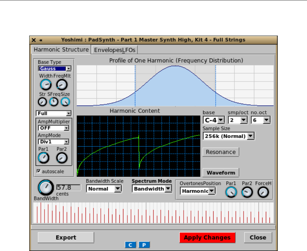
Yoshimi Software Synthesizer 11.2 PADsynth / Harmonic Structure
11.2 PADsynth / Harmonic Structure
Figure 125: PADsynth Edit Dialog
Note how, in the newer versions of Yoshimi, the part number and part name are part of the window
caption. There are a lot of parameter sections to keep track of, and to describe.
1. Basics (section)
2. Harmonic (section)
3. Resonance (section)
4. Waveform (section)
5. Bandwidth and Position (section)
6. Export (section)
7. C
8. P
9. Apply Changes
10. Close
Some of these elements have their own sections devoted to them, below.
163
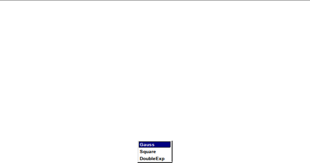
Yoshimi Software Synthesizer 11.2 PADsynth / Harmonic Structure
11.2.1 PADsynth / Harmonic Structure / Basics
1. BaseType
2. Width
3. FreqMlt
4. Str
5. SFreq
6. Size
7. Full/Upper/Lower
8. AmpMultiplier
9. AmpMode
10. Par1
11. Par2
1. BaseType. Base Type of Harmonic.
Figure 126: Base Type of Harmonic
Values: Gauss*, Square, DoubleExp
2. Width. Width of Harmonic. The lowest value yields a very thin Profile of One Harmonic
(Frequency Distribution) waveform, pretty close to a Dirac delta function (in this case, pretty close to
a sine wave). The highest value yields a broadband spectrum, almost a flat spectrum, but it has a hump
around the center frequency.
Values: 0 to 127
3. FreqMlt. Frequency Multiplier. Increasing this value causes more and more repetitions of the
harmonic spectrum frequency distribution to appear. A value of 127 yields 32 repetitions of the spectrum.
Values: 0 to 127
4. Str. Stretch. Not quite sure what this one does. Increasing it adds harmonics to the spectrum and
alters the distribution of their levels.
Values: 0 to 127
5. SFreq. Harmonic Sfreq. Not quite sure what this one does. Increasing it tightens up the spread of
harmonics.
Values: 0 to 127
6. Size. Harmonic Size. Increasing this value preserves the shape of the spectrum, but widens it.
Values: 0 to 127
7. Full/Upper/Lower. Harmonic Sidebands. These menu entries select the full spectrum, or filter in
only the upper sidebands of the spectrum, or the lower sidebands.
Values: 0 to 127
164

Yoshimi Software Synthesizer 11.2 PADsynth / Harmonic Structure
Figure 127: PADsynth Full/Upper/Lower Harmonics
Values: Full*, Upper Half, Lower Half
8. AmpMultiplier. Amplitude Multiplier. These values spread out the frequency components in
various ways.
Figure 128: PADsynth Amplitude Multiplier
Values: OFF*, Gauss, Sine, Flat
9. AmpMode. Amplitude Mode.
Figure 129: PADsynth Amplitude Mode
Values: Sum*, Mult, Div1, Div2
10. Par1. Harmonic Parameter 1. Increasing this parameter narrows the width of the central spectral
component.
Values: 0 to 127
11. Par2. Harmonic Parameter 2. Varying this parameter changes the relative amplitude of the central
spectral component and the sidebands.
Values: 0 to 127
11.2.2 PADsynth / Harmonic Structure / Harmonic
1. Profile of One Harmonic
2. Harmonic Content Window
3. base
4. smp/oct
5. no.oct
6. Sample Size
7. Resonance (section)
8. Change (section)
165
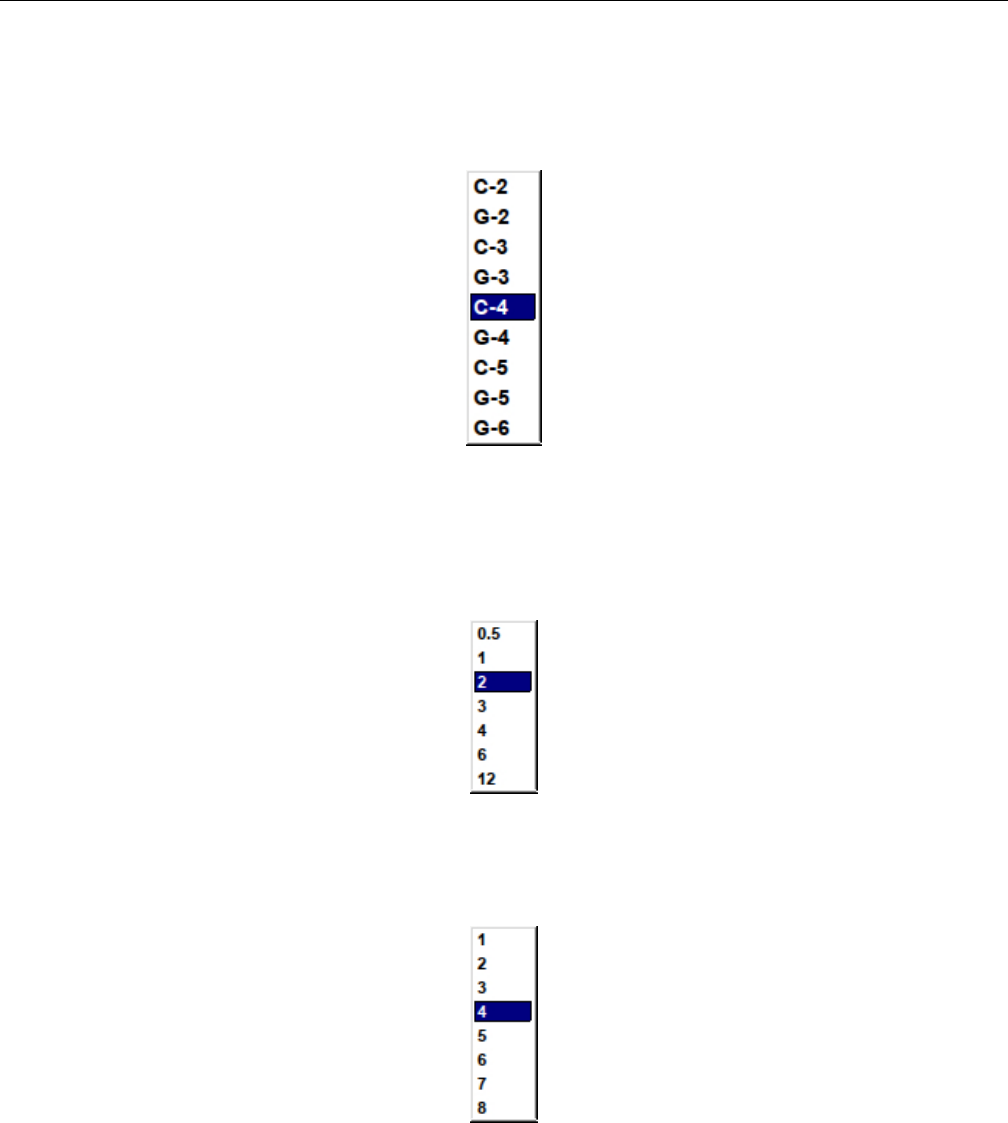
Yoshimi Software Synthesizer 11.2 PADsynth / Harmonic Structure
1. Profile of One Harmonic. Profile of One Harmonic (Frequency Distribution).
2. Harmonic Content Window. Harmonic Content Window.
3. base.
Figure 130: Harmonic Base Dropdown
Values: C-2, G-2, C-3, G-3, C-4*, G-4, C-5, G-5, G-6
4. smp/oct. Harmonic Samples Per Octave.
Figure 131: Harmonic Samples Per Octave
5. no.oct. Number of Octaves of Harmonic.
Figure 132: Harmonic Number of Octaves
Values: 1, 2, 3, 4*, 5, 6, 7, 8
6. Sample Size. Harmonic Sample Size.
166
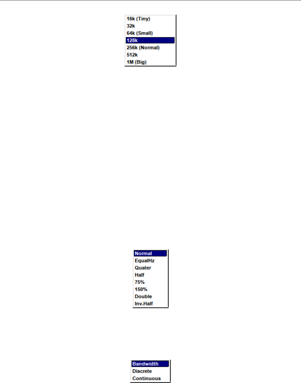
Yoshimi Software Synthesizer 11.2 PADsynth / Harmonic Structure
Figure 133: Harmonic Sample Size Dropdown
Values: 16k (Tiny), 32k, 64k (Small), 128k*, 256k (Normal), 512k, 1M (Big)
11.2.3 PADsynth / Harmonic Structure / Bandwidth and Position
1. BandWidth
2. cents
3. Bandwidth Scale
4. Spectrum Mode
5. OvertonesPosition
6. Par1
7. Par2
8. ForceH
9. Harmonics Plot
1. BandWidth. Harmonics Bandwidth.
Values: 0 to 127
2. cents. Bandwidth Reading (cents).
3. Bandwidth Scale. Bandwidth Scale.
Figure 134: Harmonics Bandwidth Scale.
Values: Normal, EqualHz, Quater, Half, 75%, 150%, Double, Inv. Half
4. Spectrum Mode. Harmonics Spectrum Mode.
Figure 135: PADsynth Harmonics Spectrum Mode
167

Yoshimi Software Synthesizer 11.2 PADsynth / Harmonic Structure
Values: Bandwidth*, Discrete, Continuous
5. OvertonesPosition. Overtones Position.
Figure 136: PADsynth Overtones Position
Values: Harmonic*, ShiftU, ShiftL, PowerU, PowerL, Sine, Power
6. Par1. PADSynth Bandwidth Parameters 1. If the Overtones Position drop-down is set to some-
thing other than Harmonic, then this knob changes the harmonic lines shown in the spectrum view just
below this item. It is best to play with this setting and observe and hear the changes it makes.
7. Par2. PADSynth Bandwidth Parameters 2. If the Overtones Position drop-down is set to some-
thing other than Harmonic, then this knob changes the harmonic lines shown in the spectrum view
(Harmonics Plot) just below this item. It is best to play with this setting and observe and hear the
changes it makes.
8. ForceH. PADSynth Bandwidth ForceH. If the Overtones Position drop-down is set to something
other than Harmonic, then this knob changes the harmonic lines shown in the spectrum view just below
this item. It is best to play with this setting and observe and hear the changes it makes.
9. Harmonics Plot. PADSynth Harmonics Plot. Shows the position and amplitude of each of the
harmonic lines that the settings will generate.
168

Yoshimi Software Synthesizer 11.2 PADsynth / Harmonic Structure
11.2.4 PADsynth / Harmonic Structure / Export
Figure 137: Harmonics Structure Export Dialog
This export dialog is a file dialog similar to other file dialogs in Yoshimi.
11.2.5 PADsynth / Harmonic Structure / Resonance
This dialog, shared in common with the ADDsynth editor, is a stock user-interface element described in
Section 6.3 ”Stock Resonance Settings” on page 80.
11.2.6 PADsynth / Harmonic Structure / Change
The Waveform button brings up the Harmonic Content editor, which is another complex dialog. Like
Figure 123 ”ADDsynth Oscillator Editor” on page 159, it allows one to create an essentially unlimited
number of oscillators.
169
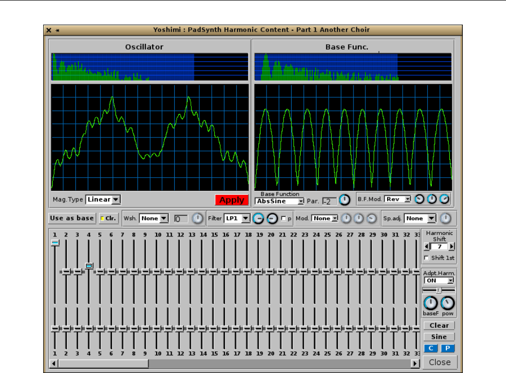
Yoshimi Software Synthesizer 11.2 PADsynth / Harmonic Structure
Figure 138: Harmonic Content Editor
This dialog is complex enough that it makes sense to break it down into sub-sections.
1. Oscillator (section)
2. Base Function (section)
3. Middle (section)
4. Harmonic (section)
11.2.6.1 PADsynth / Harmonic Structure / Change / Oscillator
1. Oscillator Spectrum Graph
2. Oscillator Waveform Graph
3. Mag.Type
4. Apply
1. Oscillator Spectrum Graph. Oscillator Spectrum Graph. This graph shows the spectrum of the
oscillator as a series of vertical lines, a kind of frequency histogram.
2. Oscillator Waveform Graph. Oscillator Waveform Graph. This graph shows the temporal wave-
form of the oscillator.
3. Mag.Type. Oscillator Magnitude Type. Sets how the magnitudes from the user interface behave.
See the values below.
170
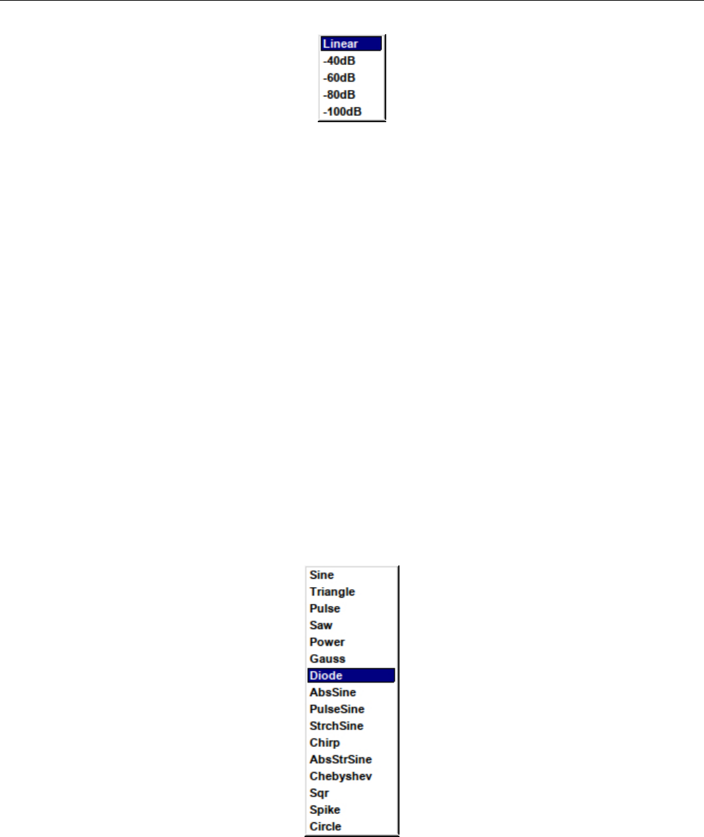
Yoshimi Software Synthesizer 11.2 PADsynth / Harmonic Structure
Figure 139: PADsynth Harmonic Content Mag Type
Values: Linear*, -40dB, -60db, -80dB, -100dB
4. Apply. PADsynth Harmonic Content Editor Apply Button.
11.2.6.2 PADsynth / Harmonic Structure / Change / Base Function
1. Base Func. Spectrum Graph
2. Base Func. Waveform Graph
3. Base F..
4. Par. Value
5. Par. Wheel
6. B.F.Mod.
7. Wheel 1
8. Wheel 2
9. Wheel 3
1. Base Func. Spectrum Graph. Harmonic Base Function Spectrum Graph.
2. Base Func. Waveform Graph. Harmonic Base Function Waveform Graph.
3. Base F. Harmonic Base Function. Sets what function to use as the harmonics base function. One
can use any base function as harmonics.
Figure 140: PADsynth Harmonic Content Base Function
Values: Sine*, Triangle, Pulse, Saw, Power, Gauss, Diode, AbsSine, PulseSine, StrchSine,
Chirp, AbsStrSine, Chebyshev, Sqr, Spike, Circle
171

Yoshimi Software Synthesizer 11.2 PADsynth / Harmonic Structure
4. Par. Value. PADsynth Parameter Value.
5. Par. Wheel. PADsynth Parameter Wheel. Change the parameter of the base function.
6. B.F.Mod. PADSynth Base Frequency Mod. This item is very similar to the Harmonic Editor
Modulation (Mod.) setting.
Values: None*, Rev, Sine, Pow
7. Wheel 1. PADsynth Wheel 1. With the B.F.Mod. selection set to something other than None, this
modifies one (unknown at this time) parameter of the modulation selection.
8. Wheel 2. PADsynth Wheel 2. With the B.F.Mod. selection set to something other than None, this
modifies one (unknown at this time) parameter of the modulation selection.
9. Wheel 3. PADsynth Wheel 3. With the B.F.Mod. selection set to something other than None, this
modifies one (unknown at this time) parameter of the modulation selection.
11.2.6.3 PADsynth / Harmonic Structure / Change / Middle
1. Use as base
2. Clr.
3. Wsh.
4. Wsh Value
5. Wsh Wheel
6. Filter
7. Filter Wheel 1
8. Filter Wheel 2
9. Filter p
10. Mod.
11. Mod. Wheel 1
12. Mod. Wheel 2
13. Mod. Wheel 3
14. Sp.adj.
15. Sp.adj. Wheel
1. Use as base. Use as Base. Convert the oscillator output to a base function. Changing the Base
function or its parameter will erase the converted base function.
2. Clr. Clear. Clear the settings and make the oscillator equal to a base function. If this is cleared, one
can click the Use as base button to make multiple conversions to base functions.
3. Wsh. Harmonic Editor Wave-shaping, ”W.sh”.
Wave shaping function that applies to the oscillator. It has one parameter that fine-tunes the wave-
shaping function.
4. Wsh Value. Harmonic Editor Wave-shaping Value.
172

Yoshimi Software Synthesizer 11.2 PADsynth / Harmonic Structure
Figure 141: PADsynth Harmonic Content Editor Wave-Shaping Function
Values: None*, Atan, Asym1, Pow, Sine, Qnts, Zigzg, Lmt, LmtU, LmtL, ILmt, Clip, Asym2,
Pow2, Sgm
The type of wave-shaping distortion has much influence on how the overtones are being placed.
Sometimes, one gets a ”fat” bass, and sometimes, high frequencies are added, making the sound ”crystal
clear”.
Atan & Sigmoid. This is the default setting. It is an easy way to apply loudness to a wave without
getting undesired high overtones. Thus, it can be used both for making instruments that sound like ”real”
ones, but also for electronic music. The transformation turns, roughly said, every amplitude into a square
amplitude. Thus, sine, power, pulse and triangle turn into a usual square wave, while a saw turns into a
phased square wave. A chirp wave turns into a kind of phase modulated square wave.
Quants (”Qnts”) Quantization adds high overtones early. It can be seen as an unnatural effect, which
is often used for electronic music. The transformation is a bit similar to building the lower sum of a wave,
mathematically said. This means that the transformation effect turns an ”endless high” sampled wave
into only a few samples. The more distortion one applies, the fewer samples will be used. Indeed, this is
equivalent to say that more input amplification is used. To see this, here is a small sample of code, where
”ws” is the (correctly scaled amount of input amplification, and ”n” the number of original samples.
If one turns on quantisation very high, one might be confused that, especially high notes, make no
sound. The reason: High frequencies are ”forgotten” if one samples with only few samples. Also, the sign
of an amplitude can be forgotten. This behaviour might make some quantisations a bit unexpected.
Limiting (”Lmt*” and ”Clip”) Limiting usually means that for a signal, the amplitude is modified
because it exceeds its maximum value. Overdrive, as often used for guitars, is often achieved by limiting:
It happens because an amplifier ”overdrives” the maximum amplitude it can deliver.
ZynAddSubFX has two types of limiting. Soft limiting, here as Lmt, means that the sound may not
exceed a certain value. If the amplitude does so, it will simply be reduced to the limiting value. The
overtones are generated in the lower frequencies first.
Hard limiting, is also called clipping and abbreviated Clip. This means that if the maximum is
exceeded, instead of being constant at the limiting value, the original signal still has some influence on
the output signal. Still, it does not exceed the limiting value. For ZynAddSubFX, a signal exceeding the
limiting value will continue to grow ”in the negative”. This leads to overtones being generated on the full
frequency band.
173
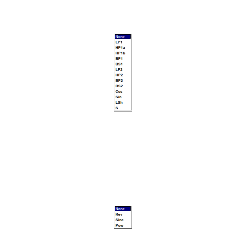
Yoshimi Software Synthesizer 11.2 PADsynth / Harmonic Structure
5. Wsh Wheel. Harmonic Editor Wave-shaping Wheel.
6. Filter. Harmonic Editor Filter. Sets the type of the harmonic filter.
Figure 142: PADsynth Harmonic Content Filter
Values: None*, LP1, HP1a, HP1b, BP1, BS1, LP2, HP2, BP2, BS2, Cos, Sin, LSh, S
7. Filter Wheel 1. Harmonic Editor Filter, Wheel 1. The knob on the left sets one filter parameter,
which is either the cutoff frequency, or, if the filter is a bandpass filter, the lower corner frequency. It is
best to play with this knob with various kinds of filters selected from the filter drop-down list.
8. Filter Wheel 2. Harmonic Editor Filter, Wheel 2. The knob on the right sets, if the filter is a
bandpass filter, the upper corner frequency. It is best to play with this knob with various kinds of filters
selected from the filter drop-down list.
9. Filter p. Harmonic Editor Filter, p. If set, the filter is applied before waveshaping.
10. Mod. Harmonic Editor Modulation.
Figure 143: PADsynth Harmonic Content Editor Modulation
Values: None*, Rev, Sine, Pow
11. Mod. Wheel 1. Harmonic Editor Modulation Wheel 1. With the Mod. selection set to something
other than None, this modifies one (unknown at this time) parameter of the modulation selection.
12. Mod. Wheel 2. Harmonic Editor Modulation Wheel 2. With the Mod. selection set to something
other than None, this modifies one (unknown at this time) parameter of the modulation selection.
13. Mod. Wheel 3. Harmonic Editor Modulation Wheel 3. With the Mod. selection set to something
other than None, this modifies one (unknown at this time) parameter of the modulation selection.
14. Sp.adj. Harmonic Editor Spectrum Adjust. Adjust the spectrum of the waveform.
RMS normalize. Enables the RMS normalization method (recommended); this keeps the same loud-
ness regardless the harmonic content.
174

Yoshimi Software Synthesizer 11.2 PADsynth / Harmonic Structure
Below are the harmonics and their phases. One can use them to add to oscillator harmonics that has
the waveform of the base function. Increasing the number of harmonics has virtually no effect on CPU
usage. Right click to set a harmonic/phase to the default value.
Figure 144: PADsynth Harmonic Content Editor Spectrum Adjust
Values: None*, Pow, ThrsD, ThrsU
15. Sp.adj. Wheel. Harmonic Editor Spectrum Adjust Wheel.
11.2.6.4 PADsynth / Harmonic Structure / Change / Harmonic
1. Harmonics Amplitude
2. Harmonics Bandwidth
3. Harmonics Scrollbar
4. Harmonic Shift
5. Harmonic Shift R
6. Harmonic Shift preH
7. Adpt.Harm.
8. Adpt.Harm. Slider
9. Adpt.Harm. baseF
10. Adpt.Harm. pow
11. Clear
12. Sine
13. C
14. P
15. Close
16. Harmonics Amplitude. Harmonics Amplitude. Provides 128 sliders for the amplitude of har-
monics.
17. Harmonics Bandwidth. Harmonics Bandwidth. Provides 128 sliders for the bandwidth of har-
monics.
18. Harmonics Scrollbar. Harmonics Scrollbar.
19. Harmonic Shift. Harmonics Shift.
20. Harmonic Shift R. Harmonics Shift Reset. Pressing this button resets the Harmonic Shift
value to zero (0).
21. Harmonic Shift preH. Harmonics Shift preH. If set, applies the harmonic shift before the filtering
and waveshaping.
22. Adpt.Harm. Adaptive Harmonics. Changes the type of the adaptive harmonics. (The tooltip
spells ”adaptive” wrong.)
175

Yoshimi Software Synthesizer 11.3 PADsynth / Envelopes and LFOs
Figure 145: PADsynth Adaptive Harmonic Type
Values: OFF*, ON, Square, 2xSub, 2xAdd, 3xSub, 3xAdd, 4xSub, 4xAdd
23. Adpt.Harm. Slider. Adaptive Harmonics Slider. If something other that OFF or ON is selected,
then this slider changes the waveform appearance. Even more informative is the change in the spectrum
that is shown. Obviously, this setting is something to play with while listening to the waveform.
24. Adpt.Harm. baseF. Adaptive Harmonics Base Frequency. If something other that OFF is selected,
then this knob changes the waveform appearance. Even more informative is the change in the spectrum
that is shown. Obviously, this setting is something to play with while listening to the waveform.
25. Adpt.Harm. pow. Adaptive Harmonics Power. If something other that OFF is selected, then this
knob changes the waveform appearance. Even more informative is the change in the spectrum that is
shown. Obviously, this setting is something to play with while listening to the waveform.
26. Clear. Harmonics Clear. Clears the harmonics settings.
27. Sine. Harmonics Sine. The user is prompted to ”Convert to sine?” This seems simply to reset the
base function to a sine wave.
28. C. Harmonics Copy.
29. P. Harmonics Paste.
30. Close. Harmonics Close.
11.3 PADsynth / Envelopes and LFOs
This dialog is reached by click on the Envelopes LFOs tab of the PADsynth parameters dialog. This
tab is next to the Harmonic Structure tab.
It consists of nothing but stock user-interface elements that are described elsewhere in this manual.
176
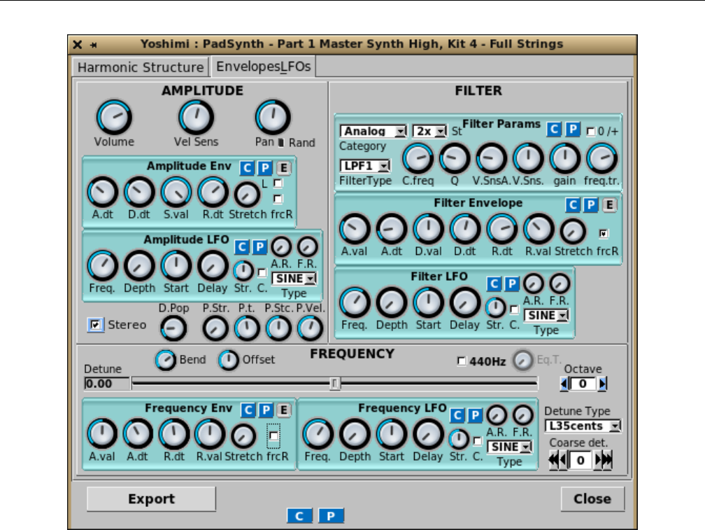
Yoshimi Software Synthesizer 11.3 PADsynth / Envelopes and LFOs
Figure 146: PADSynth Parameters, Envelopes and LFOs
1. AMPLITUDE
2. FILTER (section)
3. FREQUENCY (section)
4. Export
5. C
6. P
7. Close
One thing to note is that the small Red reset button next to the Pan knob is no longer present.
Instead, one can use a right-click on this knob to reset it to its home position and value.
Also note the ”Filter Envelope” section in the figure. This is a free-edit version of the envelope. The
non-free-edit view can be seen in Figure 73 ”Filter Envelope Sub-Panel” on page 94, which describes this
user-interface item in more detail.
31. AMPLITUDE. See Section 10.1 ”ADDsynth / AMPLITUDE” on page 145. This stock dialog
section provide volume, velocity sensing, panning, an amplitude envelope sub-panel, and an amplitude
LFO sub-panel.
32. FILTER. See Section 10.2 ”ADDsynth / FILTER” on page 147.
33. FREQUENCY. See Section 10.3 ”ADDsynth / FREQUENCY” on page 147.
177
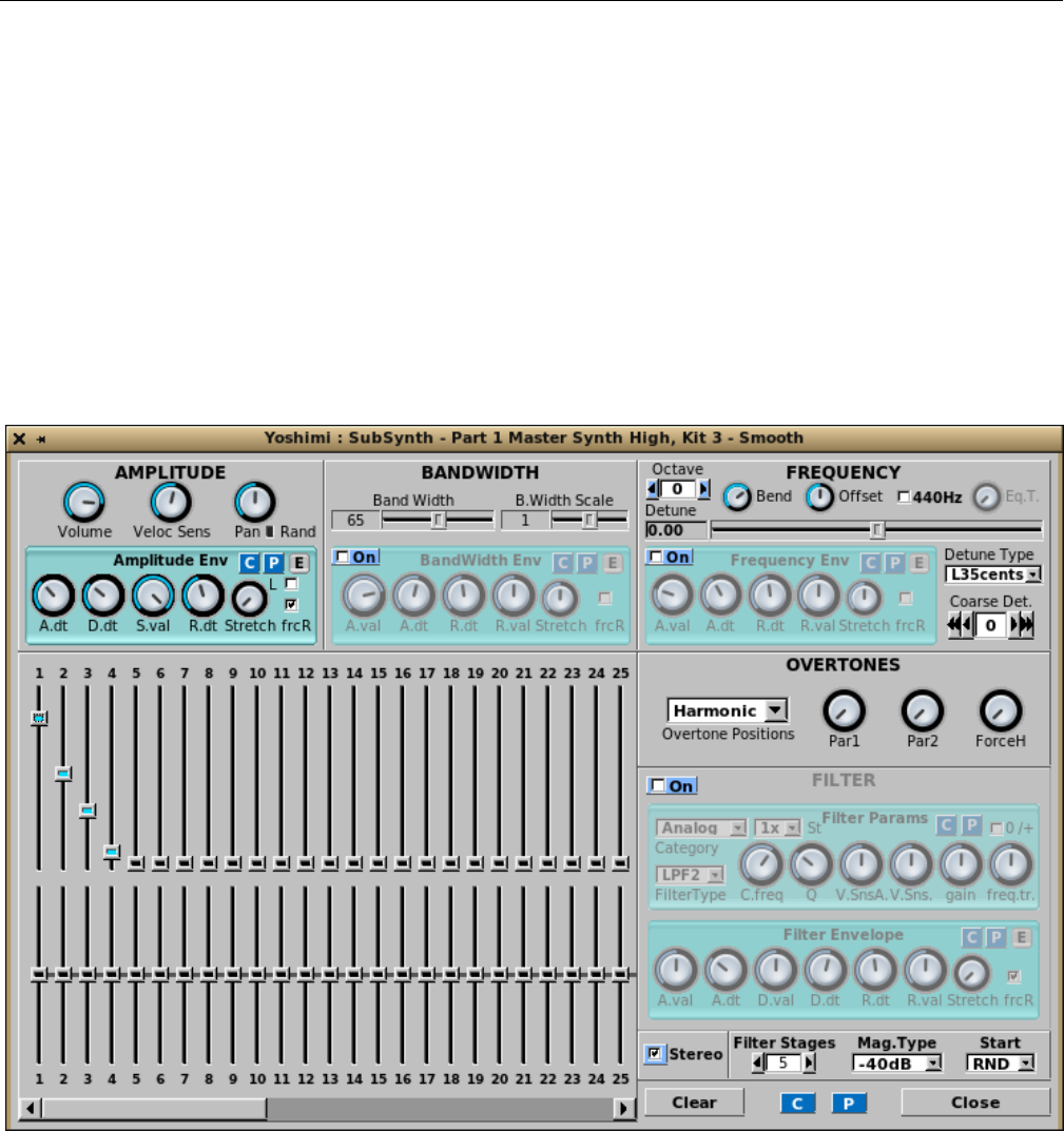
Yoshimi Software Synthesizer
34. Export. Very similar to Figure 137 ”Harmonics Structure Export Dialog” on page 169.
35. C. The stock copy dialog.
36. P. The stock paste dialog.
37. Close. Close.
12 SUBsynth
The Yoshimi SUBsynth dialog is yet another complex dialog, this time for creating a subtractive-synthesis
instrument, ”SUBsynth” or ”SUBnote” is a simple engine which makes sounds through subtraction of
harmonics from white noise. [27]
Figure 147: SUBsynth Edit Dialog
One thing to note is that the small Red reset button next to the Pan knob is no longer present.
Instead, one can use a right-click on this knob to reset it to its home position and value.
This dialog, though very complex, consists of a number of stock sections that are described elsewhere
in this manual. Some descriptions are repeated here, though.
1. AMPLITUDE (section)
2. BANDWIDTH (section)
178

Yoshimi Software Synthesizer 12.1 SUBsynth / AMPLITUDE
3. FREQUENCY (section)
4. OVERTONES (section)
5. FILTER (section)
6. Harmonics (section)
7. Clear
8. C
9. P
10. Close
12.1 SUBsynth / AMPLITUDE
1. Volume
2. Vel Sens
3. Pan
4. Rand
5. Reset (panning) (red button)
6. Amplitude Env (stock sub-panel)
1. Volume. SUBsynth Volume.
Values: 1 to 127, 64*
2. Vel Sens. Velocity Sensing function, rightmost/max to disable.
Values: 1 to 127, 64*
3. Pan. Global panning, leftmost/zero gives random panning.
Values: 1 to 127, 64*
4. Rand. Indicator for activation of random panning.
5. Reset (panning). Reset Panning.
6. Amplitude Env. Amplitude Envelope. See Section 6.5.1 ”Amplitude Envelope Sub-Panel” on
page 89, for information on this stock sub-panel.
12.2 SUBsynth / BANDWIDTH
1. BandWidth
2. B.Width Scale
3. Bandwidth Env
1. BandWidth. SUBsynth Bandwidth. Sets the bandwidth of each harmonic.
Values: 1 to 127, 40*
2. B.Width Scale. SUBsynth Bandwidth Scale. Sets how the bandwidth of each harmonic is increased
according to the frequency. The default (0) increases the bandwidth linearly according to the frequency.
This setting is kind of a ”frequency stretch” parameter.
Values: -64 to 63, 0*
3. Bandwidth Env. SUBsynth Bandwidth.
1. Enabled
2. A.val
179

Yoshimi Software Synthesizer 12.3 SUBsynth / FREQUENCY
3. A.dt
4. R.dt
5. R.val
6. Stretch
7. frcR
8. C
9. P
10. E
1. Enabled. Enable the panel.
2. A.val. Attack value. We need to figure out what this means.
Values: 0 to 127, 64*
3. A.dt. Attack duration. Attack time.
Values: 0 to 127, 40*
4. R.dt. Release time.
Values: 0 to 127, 60*
5. R.val. Release Value. Actually present only on the Frequency Env sub-panel.
Values: 0 to 127, 64*
6. Stretch. Bandwidth Stretch. On lower notes make the bandwidth lower.
Values: 0 to 127, 64*
7. frcR. Forced release. If this option is turned on, the release will go to the final value, even if the
sustain level is not reached.
Also present in this sub-panel are the usual Copy and Paste buttons that call up a copy-parameters
or paste-parameters dialog, as well as a button to bring up the editor window.
Values: Off, On*
12.3 SUBsynth / FREQUENCY
1. Detune
2. FREQUENCY Slider
3. 440Hz
4. Eq.T
5. Octave
6. Detune Type
7. Coarse Det.
8. Frequency Env
1. Detune. Frequency Detune Indicator
2. FREQUENCY Slider. Frequency Slider.
Values: -35 to 34.99
3. 440Hz. Frequency 440Hz. Fixes the base frequency to 440Hz. One can adjust it with detune settings.
4. Eq.T. Frequency Equalize Time. Sets how the frequency varies according to the keyboard. Set to
the leftmost setting for a fixed frequency.
180
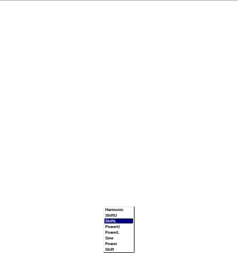
Yoshimi Software Synthesizer 12.4 SUBsynth / OVERTONES
5. Octave. Frequency Octave. Octave Shift.
6. Detune Type. Frequency Detune Type. Sets the ”Detune” and ”Coarse Detune” behavior
7. Coarse Det. Frequency Coarse Detune, ”C.Detune”.
8. Frequency Env. Frequency Envelope Stock Sub-Panel.
1. Enable
2. A.value or A.val
3. A.dt
4. R.dt
5. R.val
6. Stretch
7. frcR
8. C
9. P
10. E
See Section 70 ”Amplitude/Filter/Frequency Envelope Editor” on page 91, for more details.
12.4 SUBsynth / OVERTONES
The harmonics settings controls the harmonic intensities/relative bandwidth. Moving the sliders upwards
increases the relative bandwidth. Please note that, if one increases the number of harmonics, the CPU
usage increases. Right click to set the parameters to default values.
1. Overtones Position
2. Par1
3. Par2
4. ForceH
1. Overtones Position. Subsynth Overtones Position.
Values: Harmonic, ShiftU, ShiftL, PowerU, PowerL, Sine, Power, Shift
Figure 148: Harmonic Type Dropdown
2. Par1. Subsynth Overtones Par1.
Values: 0 to 127
3. Par2. Subsynth Overtones Par2.
Values: 0 to 127
4. ForceH. Subsynth Overtones ForceH.
Values: 0 to 127
181
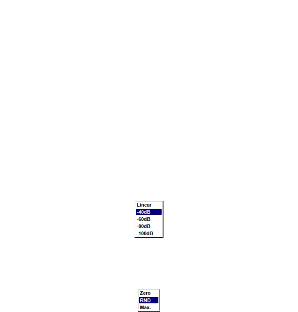
Yoshimi Software Synthesizer 12.5 SUBsynth / FILTER
12.5 SUBsynth / FILTER
1. Enabled
2. Filter Params (stock sub-panel)
3. Filter Env (stock sub-panel)
4. Stereo
5. Filter Stages
6. Mag. Type
7. Start
1. Enabled. SUBsynth Filter Enabled.
2. Filter Params. Filter Params. See Section 6.2.5 ”Filter Parameters User Interface” on page 78,
which describes this stock sub-panel.
3. Filter Env. Filter Params. See Section 6.5.5 ”Envelope Settings for Filter” on page 94, which
describes this stock sub-panel.
4. Stereo. SUBsynth Stereo. Make the instrument stereo. The CPU usage goes up about 2 times. This
item isn’t really a FILTER item, it is just located in that same area.
5. Filter Stages. Filter Stages. Filter Order. Sets the number of filter stages applied to white noise.
This parameter affects the CPU usage.
Values: 0, 1, 2*, 3, 4, 5
6. Mag. Type. Magnitude Type. Sets the type of magnitude settings (linear versus dB values)
Figure 149: SUBSynth Magnitude Type Dropdown
Values: Linear, -40dB, -60dB, -80dB, -100dB
7. Start. Start Type. How to start the filters.
Figure 150: SUBsynth Start Type
Values: Zero, RND, Max.
12.6 SUBsynth / Harmonics
This section consists of 64 sliders to control the amplitude of the narrow noise band at a given harmonic,
and 64 sliders to control the bandwidth of each band.
182
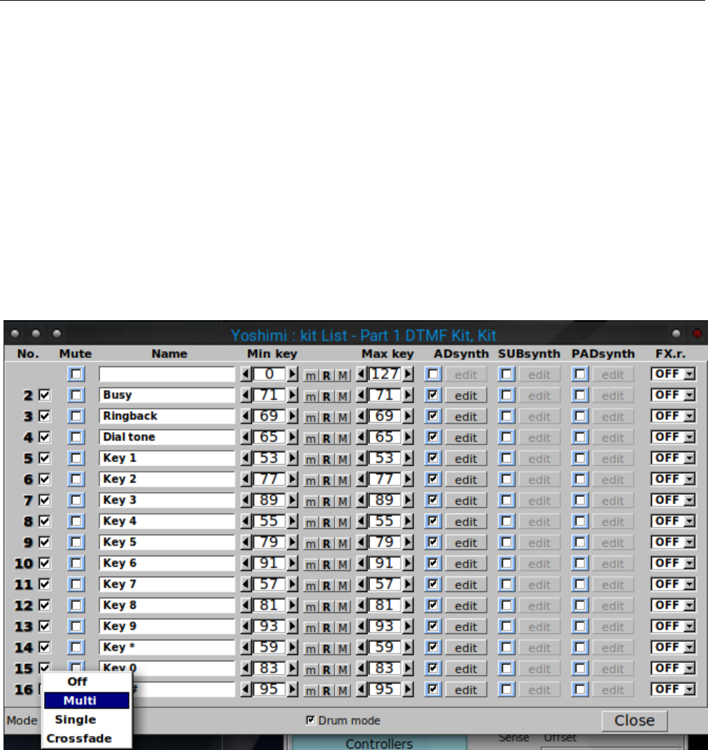
Yoshimi Software Synthesizer
The top row of SUBsynth sliders sets the relative amplitude. This used of the word ”relative” is an
important distinction, as the overall level of the output is normalised; all actual levels will be dependent
on whichever is the highest.
The bottom row sets the bandwidth of each harmonic. If one has just the fundamental, and drops the
bandwith to the minimum, one gets very nearly a sinewave. Set it to maximum and it is very obviously
filtered noise.
13 Kit Edit
The Yoshimi Kit dialog is a dialog for creating a set of drums or layered instruments. It provides a way
to use individual voices and synth blocks to create drumlike sounds, or complex layered sounds. Within
this window one can create drum kits, layered instruments, or one can combine more instruments into
one instrument.
Figure 151: Kit Edit Dialog
There have been some minor changes in this figure in recent versions of Yoshimi.
1. Rows 1 to 16. This dialog contains 16 identical rows containing the following elements, in the
order given:
1. No.
2. Enable (unlabelled checkbox)
3. Mute (was called ”M”)
4. Name (Instrument Name)
183

Yoshimi Software Synthesizer
5. Min key
6. m(set minimum note)
7. R(reset default note range)
8. M(set maximum note)
9. Max key
10. ADsynth
1. Enable
2. edit
11. SUBsynth
1. Enable
2. edit
12. PADsynth
1. Enable
2. edit
13. FX.r.
2. Mode
3. Drum mode
4. Close
1. No. Kit Row Number, Kit Item Number. A simple label to indicate the instrument number in the
kit.
2. Enable. Kit Row Enable. This unlabelled checkbox enables or disables an instrument in the kit.
Value: Off*, On
3. Mute. Kit Row ”M”, now labelled as ”Mute”. Mute an item of the kit.
4. Instrument Name. Kit Instrument Name.
5. Min key. Kit Instrument Minimum Key, was formerly labelled ”Min.k”. Sets the minimum key of
the item of the kit.
6. m. Sets the minimum note of this instrument to value of the last note pressed.
7. R. Resets the minimum and maximum notes to their default values.
8. M. Sets the maximum note of this instrument to value of the last note pressed.
9. Max key. Kit Instrument Maximum Key, was formerly labelled ”Max.k”. Sets the maximum key
of the item of the kit.
10. ADsynth. Kit ADDsynth. A checkbox is provided to enable/disable this synth component, and
an edit button is provided to edit the component.
11. SUBsynth. Kit SUBsynth. A checkbox is provided to enable/disable this synth component, and
an edit button is provided to edit the component.
12. PADsynth. Kit PADsynth. A checkbox is provided to enable/disable this synth component, and
an edit button is provided to edit the component.
13. FX.r. Kit Effect. Chooses the Part Effect (PartFX) to process the item (OFF means that is
unprocessed).
Values: OFF, FX1, FX2, FX3
14. Mode. Kit Mode.
We need a picture to show the full Mode menu.
184

Yoshimi Software Synthesizer
•Off means no kit is enabled, so one only has the Add, Sub, and Pad sounds in the Instrument Edit
window.
•Multi means all the kit items will sound together regardless of their note ranges.
•Single means only the lowest numbered item will sound in a given note range. There will be no
overlap.
•Crossfade is described in detail below.
For example: Item 1 has Min key set to 0 and Max key set to 60, and Item 2 has Min key set to
40 and Max key set to 127.
In Single mode, only Item 1 will sound in the note range 0 to 60, and Item 2 will sound in the
range 61 to 127.
In Multi mode, only Item 1 will sound in the range 0 to 40, both items will sound from 41 to 60,
and only Item 2 will sound from 61 to 127.
Values: Off*, Multi, Single, Crossfade.
The part’s kit edit Mode menu has an additional entry called Crossfade. When crossfade is set, one
gets Multi behaviour with overlapping key ranges, but with a very smooth crossfade between sequential
pairs of kit items. This follows the pattern 1+2, 3+4, etc. Each pair will not affect any other kit items.
It doesn’t matter which of the pair has the lower range, as long as there is a range overlap. The code
is semi-intelligent, and any that are not paired will exhibit normal Multi behaviour. If one item in a pair
is not enabled then the other one will exhibit normal Multi behaviour and will not fade at all.
An interesting effect is that if one of the pair is enabled, but muted or has no engines enabled, then
the other one still fades through the overlap range, so one can get sounds fading out (or fading in) with
increasing pitch!
If one wants a fade to come in then go out again, one needs two sets of pairs, with a hard non-
overlapped point in the middle.
item 1 - min 0 max 60
item 2 - min 40 max 80 (fades up)
item 3 - min 81 max 100 (fades down)
item 4 - min 90 max 127
This feature is backward-compatible, in that older versions of Yoshimi will see it as an ordinary
Multi – it uses a new variable stored in the instrument file that is simply ignored by earlier versions.
15. Drum mode. Kit Drum Mode. If drum-mode is set, then microtonal tuning is ignored for this
kit, otherwise it could make drum sounds very unpredictable!
16. Close Window. Close.
One kit mode is set, some direct-access to the kit mode is available. We’ll set it to ’multi’.
direct 1 64 58 0
Kit item 1 is always enabled, although one can mute it and enable/disable the individual engines. To
be clear, though, we’ll enable kit item 3 and work with that; add 32 to the kit number to get 35:
185

Yoshimi Software Synthesizer
direct 1 64 8 0 35
direct 56 64 16 0 35 // set its minimum note
direct 1 64 8 0 35 1 // enable the subsynth engine
direct 40 64 0 0 3 1 // change its volume
Note one adds 32 only for the kit item commands, not for the engine internal commands.
14 Banks Collection
In this section, we attempt to collect and summarize all of the existing banks for Yoshimi and Zy-
nAddSubFX that we can find. Many of them are supplied by the two projects.
Between all of the collections, there is a large amount of duplication. There is also semi-duplication,
with slight variations on the same basic instrument. Various Linux distributions which package Zy-
nAddSubFX and Yoshimi might add some banks to their versions of these packages. Thus, there are
far more sound settings than we can discuss and categorize.
One thing we’re looking for is a good General MIDI (GM) bank for Yoshimi. As part of our Yoshimi
Cookbook [4], we include a basic General MIDI bank for. However, there are number of patches with no
good implementation in it.
14.1 Yoshimi Banks
Yoshimi comes with the following banks, which may be found in /usr/share/yoshimi/banks as installed
by the installer. In this case, it is the Debian installer.
1. Arpeggios. Also in ZynAddSubFX.
2. Bass. Also in ZynAddSubFX.
3. Brass. Also in ZynAddSubFX.
4. chip.
5. Choir and Voice Also in ZynAddSubFX, slightly different bank name.
6. Drums. Also in ZynAddSubFX, but with only one drum kit included.
7. Dual. Also in ZynAddSubFX.
8. Fantasy. Also in ZynAddSubFX.
9. Guitar. Also in ZynAddSubFX.
10. Misc. Also in ZynAddSubFX.
11. Noises. Also in ZynAddSubFX.
12. Organ. Also in ZynAddSubFX.
13. Pads. Also in ZynAddSubFX.
14. Plucked. Also in ZynAddSubFX.
15. Reed and Wind. Also in ZynAddSubFX, slightly different bank name.
16. Rhodes. Also in ZynAddSubFX.
17. Splited. Also in ZynAddSubFX, slightly different bank name.
18. Strings. Also in ZynAddSubFX.
19. Synth. Also in ZynAddSubFX.
20. SynthPiano. Also in ZynAddSubFX.
21. The Mysterious Bank. Also in ZynAddSubFX, slightly different bank name. ZynAddSubFx has
three more mysterious banks (see next section).
186

Yoshimi Software Synthesizer 14.2 Additional ZynAddSubFX Banks
22. Will Godfrey Collection.
23. Will Godfrey Companion.
14.2 Additional ZynAddSubFX Banks
ZynAddSubFX comes with the following banks, which may be found in the source code [30] or installation
packages of this project. ZynAddSubFX has some of the same banks (as far as we can tell) as Yoshimi,
but with the following additions:
1. Companion.
2. Cormi Noise and Cormi Sound [6].
3. Laba170bank.
4. olivers-100. Some very good instruments, including sitar and steel drums.
5. the mysterious bank.
6. the mysterious bank 2.
7. the mysterious bank 3.
8. the mysterious bank 4.
14.3 Additional Banks
Here are some additional banks we have found, or have built ourselves. It often happens that, later on,
a site is no longer available. Or we forget from whence we got the banks. In these cases, the banks are
stored in the contrib/banks directory of this project.
1. Alex J The site seems to be gone/expired. So one will find these in the ”contrib/banks” directory
for safekeeping.
2. Bells We have no idea where we got this one. Lost track of that information.
3. C Ahlstrom These are mine, but not yet made into a systematic bank. They are included with
this document.
4. Chromatic Percussion Not sure where we got this at this time.
5. Drums DS Not sure where we got this at this time.
6. Electric Piano Not sure where we got this at this time.
7. Flute Not sure where we got this at this time.
8. folderol collection [8], also found at [26].
9. Internet Collection Not sure where we got this at this time.
10. Leads Not sure where we got this at this time.
11. Louigi Verona Workshop The site seems to be gone/expired. So one will find these in the ”con-
trib/banks” directory for safekeeping.
12. Misc Keys Not sure where we got this at this time.
13. mmxgn Collection [12]
14. Piano Not sure where we got this at this time.
15. RB Zyn Presets Not sure where we got this at this time.
16. Vanilla See [26] for this bank, and for some demonstration files of ZynAddSubFX sounds, and some
other nice links.
17. VDX Not sure where we got this at this time.
18. x31eq.com [18]
19. XAdriano Petrosillo Not sure where we got this at this time.
20. Zen Collection Not sure where we got this at this time.
187

Yoshimi Software Synthesizer
15 Non-Registered Parameter Numbers
This section comes from the source-code documentation file Zyn nrpn.txt or the ZynAddSubFx online
manual [27] and the Using NRPNS.txt document that accompanies the Yoshimi source code.
Yoshimi implements System and Insertion effects control in a manner compatible with ZynAddSubFX.
As with all Yoshimi’s NRPNs, the controls can be sent on any MIDI channel.
15.1 NRPN / Basics
NRPN stands for ”Non Registered Parameters Number”. NRPNs can control all System and Insertion
effect parameters. Using NRPNs, Yoshimi can now directly set some part values regardless of what channel
that part is connected to. For example, one may change the reverb time when playing to keyboard, or
change the flanger’s LFO frequency. The controls can be sent on any MIDI channel (the MIDI channels
numbers are ignored).
The parameters are:
•NRPN MSB (coarse) (99 or 0x63) sets the system/insertion effects (4 for system effects or 8 for
insertion effects). We abbreviate this value as Nhigh.
•NRPN LSB (fine) (98 or 0x62) sets the number of the effect (first effect is 0). We abbreviate this
value as Nlow.
•Data entry MSB (coarse) (6) sets the parameter number of effect to change (see below). We
abbreviate this value as Dhigh.
•Data entry LSB (fine) (26) sets the parameter of the effect. We abbreviate this value as Dlow.
One must send NRPN coarse/fine before sending Data entry coarse/fine. If the effect/parameter
doesn’t exists or is set to none, then the NRPN is ignored.
It’s generally advisable to set NRPN MSB before LSB However, once MSB has been set one can set
a chain of LSBs if they share the same MSB. The data CCs associated with these are 6 for MSB and 38
for LSB. Only when an NRPN has been established can the data values be entered (they will be ignored
otherwise). If a supported control is identified, these data values will be stored locally (if needed) so that
other NRPNs can be set. Whenever either byte of the NRPN is changed, the data values will be cleared
(but stored settings will not be affected). If either NRPN byte is set to 127, all data values are ignored
again.
In Yoshimi NRPNs are not themselves channel-sensitive, but the final results will often be sent to
whichever is the current channel. Yoshimi also supports the curious 14-bit NRPNs, but this shouldn’t be
noticeable to the user. In order to deal with this, and also some variations in the way sequencers present
NRPNs generally, if a complete NRPN is set (i.e. Nhigh,Nlow,Dhigh,Dlow), then the data bytes can be
in either order, but must follow Nhigh and Nlow.
(In these notes, where practical we also list the 14 bit values in square brackets.)
After this, for running values, once Dhigh and Dlow have been set if one changes either of these, the
other will be assumed. For example, starting with Dhigh = 6 and Dlow = 20:
Change Dlow to 15 and Yoshimi will regard this as a command Dhigh 6 + Dlow 16 Alternatively
change Dhigh to 2 and Yoshimi will regard this as a command Dhigh 2 + Dlow 20. This can be useful but
may have unintended consequences! If in doubt change either of the NRPN bytes and both data bytes
will be cleared.
188

Yoshimi Software Synthesizer 15.1 NRPN / Basics
Additionally there is 96 for data increment and 97 for decrement.
Data increment and decrement operation enables one to directly change the data LSB by between 0
and 63. To change the MSB, add 64 to cover the same range. Setting 0 might seem pointless, but it gives
an alternative way to make an initial setting if one’s sequencer doesn’t play nice.
Although data increment and decrement are only active if a valid NRPN has been set, they are
otherwise quite independent single CCs. For example:
Start Value Command value Result
----- ----- -------------- ------
LSB 5 inc 20 25
MSB 7 inc 68 11
LSB 128(off) inc 1 1
MSB 126 dec 74 116
MSB 128(off) dec 65 127
A small example (all values in this example are hex):
B0 63 08 // Select the insertion effects
B0 62 01 // Select the second effect (remember: the first is 00 and not 01)
B0 06 00 // Select the effect parameter 00
B0 26 7F // Change the parameter of effect to the value 7F (127)
WARNING: Changing of some of the effect parameters produces clicks when sounds passes thru
these effects. We advise one to change only when the sound volume that passes through the effect is very
low (or silence). Some parameters produce clicks when they are changed rapidly.
Here are the effects parameter numbers (for Data entry, coarse). The parameters that produces clicks
are written in red and have (AC) after their entry (always clicks). The parameter that produces clicks
only when they are changed fast are written in blue and have a (FC) after the entry (Fast Clicks).
Most parameters have the range from 0 to 127. When parameters have another range, it is written as
”(low...high)”.
Here are the basic formats:
1. Send NRPN:
•MSB = 64 (same as for vectors)
•LSB = 0
2. Send Data MSB (6); all value ranges start from zero, not 1.
•0 : data LSB = part number
•1 : data LSB = program number
•2 : data LSB = controller number
•3 : data LSB = controller value
•4 : data LSB = part’s channel number (16 to 31 allows only Note Off for this part, while
numbers 32 or above disconnects the part from all channel message)
•5 : data LSB = part’s audio destination, one of 1 = main L&R; 2 = direct L&R; 3 = both; all
other values are ignored
•7 : data LSB = main volume (not yet implemented)
•35 (0x23) : data LSB = controller LSB value (not yet implemented)
189

Yoshimi Software Synthesizer 15.2 NRPN / Effects Control
•39 (0x27) : data LSB = main volume LSB (not yet implemented)
•64 (0x40) : data LSB = key shift value (64 = no shift)
•Other values are currently ignored.
Other values are currently ignored by Yoshimi.
15.2 NRPN / Effects Control
15.2.0.1 Reverb
•00 - Volume or Dry/Wet (FC)
•01 - Pan (FC)
•02 - Reverb Time
•03 - Initial Delay (FC)
•04 - Initial Delay Feedback
•05 - reserved
•06 - reserved
•07 - Low Pass
•08 - High Pass
•09 - High Frequency Damping (64..127) 64=no damping
•10 - Reverb Type (0..1) 0-Random, 1-Freeverb (AC)
•11 - Room Size (AC)
15.2.0.2 Echo
•00 - Volume or Dry/Wet (FC)
•01 - Pan (FC)
•02 - Delay (AC)
•03 - Delay between left and right (AC)
•04 - Left/Right Crossing (FC)
•05 - Feedback
•06 - High Frequency Damp
15.2.0.3 Chorus
•00 - Volume or Dry/Wet (FC)
•01 - Pan (FC)
•02 - LFO Frequency
•03 - LFO Randomness
•04 - LFO Type (0..1)
•05 - LFO Stereo Difference
•06 - LFO Depth
•07 - Delay
•08 - Feedback
•09 - Left/Right Crossing (FC)
•10 - reserved
•11 - Mode (0..1) (0=add, 1=subtract) (AC)
190

Yoshimi Software Synthesizer 15.2 NRPN / Effects Control
15.2.0.4 Phaser
•00 - Volume or Dry/Wet (FC)
•01 - Pan (FC)
•02 - LFO Frequency
•03 - LFO Randomness
•04 - LFO Type (0..1)
•05 - LFO Stereo Difference
•06 - LFO Depth
•07 - Feedback
•08 - Number of stages (0..11) (AC)
•09 - Let/Right Crossing (FC)
•10 - Mode (0..1) (0=add, 1=subtract) (AC)
•11 - Phase
15.2.0.5 AlienWah
•00 - Volume or Dry/Wet (FC)
•01 - Pan (FC)
•02 - LFO Frequency
•03 - LFO Randomness
•04 - LFO Type (0..1)
•05 - LFO Stereo Difference
•06 - LFO Depth
•07 - Feedback
•08 - Delay (0..100)
•09 - Left/Right Crossing (FC)
•10 - Phase
15.2.0.6 Distortion
•00 - Volume or Dry/Wet (FC)
•01 - Pan (FC)
•02 - Left/Right Crossing
•03 - Drive (FC)
•04 - Level (FC)
•05 - Type (0..11)
•06 - Invert the signal (negate) (0..1)
•07 - Low Pass
•08 - High Pass
•09 - Mode (0..1) (0=mono,1=stereo)
15.2.0.7 EQ
•00 - Gain (FC)
All other settings of the EQ are shown in a different way. The N represent the band (”B.” setting in
the UI) and the first band is 0 (and not 1), like it is shown in the UI. Change the ”N” with the band one
likes. If one wants to change a band that doesn’t exist, the NRPN will be ignored.
191

Yoshimi Software Synthesizer 15.2 NRPN / Effects Control
•10+N*5 - Change the mode of the filter (0..9) (AC)
•11+N*5 - Band’s filter frequency
•12+N*5 - Band’s filter gain
•13+N*5 - Band’s filter Q (bandwidth or resonance)
•14+N*5 - reserved
Example of setting the gain on the second band in the EQ module:
•The bands start counting from 0, so the second band is 1 =<N=1.
•The formula is 12+N*5 =<12+1*5=17, so the number of effect parameter (for Data entry coarse)
is 17.
15.2.0.8 DynFilter
•0 - Volume
•1 - Pan
•2 - LFO Frequency
•3 - LFO Randomness
•4 - LFO Type
•5 - LFO Stereo Difference
•6 - LFO Depth
•7 - Filter Amplitude
•8 - Fitler Amplitude Rate Change
•9 - Invert the signal (negate) (0..1)
Click behaviour of DynFilter has not yet been tested.
15.2.0.9 Yoshimi Extensions
If the Data MSB bit 6 is set (64) then Data LSB sets the effect type instead of a parameter number. This
must be set before making a parameter change.
•0 - Reverb
•1 - Echo
•2 - Chorus
•3 - Phaser
•4 - AlienWah
•5 - Distortion
•6 - EQ
•7 - DynFilter
For Insert effects, if the Data MSB bit 5 (32) is set and Data MSB bit 6 (64) is set (i.e. a combined
value of 96), then Data LSB sets the destination part number. 127 is off and 126 is the Master Output.
A complete example:
•99 - 8 ˜insert effects
•98 - 3 ˜number 4 (as displayed)
192

Yoshimi Software Synthesizer 15.3 NRPN / Dynamic System Settings
•6 - 32 ˜set destination
•38 - 126 ˜Master Out
•99 - 8 *
•98 - 3 *
•6 - 64 ˜change effect
•38 - 4 ˜Alienwah
•99 - 8 *
•98 - 3 *
•6 - 0 ˜Dry/Wet
•38 - 30 ˜value
Notes (*): these repeats are not needed for Yoshimi, but some sequencers are unhappy without them.
Changing just a parameter on an existing system effect:
•99 - 4 ˜system effects
•98 - 0 ˜the first effect
•6 - 1 ˜Pan
•38 - 75 ˜value
15.3 NRPN / Dynamic System Settings
Almost all dynamic setup (i.e. that doesn’t require a restart) can now be done via NRPNs, so a MIDI file
can manage Yoshimi starting from a pretty random state, and set up important features like Bank and
Program Change behavior and the number of available parts.
In parallel with this setup, there is a command to list all of these settings. One can also list the
available bank roots, the banks in any root, and instruments in any bank, along with their numeric IDs.
These IDs can then be used with normal MIDI CCs to get exactly the instrument you want at any time.
This arrangment looks positively steam-punk, but is actually very easy to use, requiring only a
command line interface and any utility that can send MIDI CCs. NRPNs aren’t special. They are simply
a specific pattern of CCs. Yoshimi’s implementation is very forgiving, doesn’t mind if you stop halfway
through (will just get on with other things while it waits), and will report exactly what it is doing. So ...
... If Yoshimi has been started from the command line (but not necessarily in the no-GUI mode), all
of the system settings that don’t require a restart can now be viewed by sending the appropriate NRPN.
Most of them can also be changed in this way. To access this functionality, set NRPN MSB (CC 99) to
64 and NRPN LSB (CC 98) to 2 (8130).
After that send the following DATA values. Commands with LSB x don’t actually use DATA LSB,
but one still needs to send it (unless it has already been set by a previous command in this control group).
193

Yoshimi Software Synthesizer
Table 1: Dynamic System Commands
DATA MSB DATA LSB Setting
2 LSB key Set master key shift, 52<=key<=76 (-36 to +36)
7 LSB volume Set master Volume ’volume’
64-79 LSB key Set channel-based (MSB-64) key shift, key-64 (-36 to +36)
80 root Set CC to control Root path change (¿119 disables)
81 bank Set CC to control Bank change (¿119 disables)
82 ¿63 Enable Program change otherwise disable
83 ¿63 Enable activation of part when program changed
84 extended Set CC control Extended program change (¿119 disables)
85 parts Set number of available parts (16, 32 or 64)
86 x Save all dynamic settings
Yoshimi can run with neither GUI nor CLI input access. Working purely as a hidden MIDI device.
To enable a tidy close, there is a new short-form NRPN. Just send 68 to both MSB and LSB (CC 99 and
CC 98).
16 Vector Control
This section comes from the source-code documentation file doc/Vector Control.txt. Also see Sec-
tion 6.1.8 ”Automation” on page 74, for a discussion of vector automation, and Section 16.2 ”Vector
Dialogs” on page 195, for a discusson of the vector configuration dialog.
Vector load and save also work from the command-line, for a complete vector set, with all mappings,
instruments, etc. One can independently decide which channel to load and save from, so one can actually
build up a vector set in (say) channel 3, then later decide to use it in channel 7. The vector settings file
has the extension .xvy standing for Xml / Vector / Yoshimi.
Vector controls can be set on any and all channels, stored in both patch sets and saved state.
16.1 Vector / Basics
Vector control is a way to control more than one part with the controllers. It is a little bit reminiscent
of the ”vector” control knob on the Yamaha PSS-790 consumer MIDI synthesizer. Vector control is only
possible if one has 32 or 64 parts active. Setup is per MIDI channel, so one can have totally different
vector behaviour on, say, channel 1 and channel 5. The term base channel refers to the incoming MIDI
channel that a particular vector setup will respond to, and the base channel directly relates to the 1 to
16 range of parts in the mixer panel.
Vector control has been extended so that there are four independent ’features’ that each axis can
control. One is fixed as Volume (if enabled) but the other three can be any valid CC, and can also be
reversed. The vector ’sweep’ CCs are split out very early in the MIDI chain, and the new CCs created
are fed back in before any other processing. The result of this is that once we eventually get MIDI-learn
implemented, the control possibilities will expand dramatically.
In vector mode parts will still play together but the vector controls can change their volume, pan,
filter cutoff in pairs, controlled by user-defined CCs set up with NRPNs.
194

Yoshimi Software Synthesizer 16.2 Vector Dialogs
One must set the X axis CC before the Y axis, but if one doesn’t set the Y axis at all, one can run
just a single axis. If one has only 32 parts active, Y settings are ignored. One cannot make any Y axis
settings until, at the very least, the X CC has be set, and if one sets that back to zero, the Y axis is
again disabled. Setting an X axis control CC will immediately enable the base channel part and the part
number + 16, as well as setting Yoshimi for 32 parts, if it was less than that. If it was the same, or was set
to 64 parts, then nothing changes. Setting the CC will also ensure that both parts are actually responding
to that MIDI channel (they might have been set to something else, or even disabled).
Setting a Y axis control CC will immediately enable the part (base channel + 32) and the part
number + 48, as well as setting for 64 parts, if it was less than that. If it was the same, again nothing
changes, and again the parts are set to the correct MIDI channel.
The instruments that are loaded into the respective parts are always shown, regardless of whether
there is a configured vector or not. They are a direct analogue of the main part instrument selector and
behave in the same way (i.e. click on them to open the instrument selection window). There are tooltips
for these items, along with the base channel and controller.
The features are pretty self descriptive as soon and you click on them. They apply inversely to the
pair of instruments on each axis. One could have all four if One wanted to, but it would probably sound
messmessy
Options are pretty obvious, and follow a familiar pattern for load, save, etc. Loading or saving a
vector will put the leafname in the bottom text field.
Disabling or clearing vectors will not change the number of parts because they may have already
been set to increased numbers for some other purpose. Similarly, disabling or clearing vectors will not
clear any instrument patches that have been loaded. Of course making any changes to the parts outside
vector control will likely mess them up. It won’t do any harm, just be puzzling.
For example: parts 1 and 17 can be set as x1 & x2 (volume only) while parts 33 and 49 can be y1 &
y2 (pan only).
Independently of this Parts 2 & 18 could use filter and pan from another CC.
16.2 Vector Dialogs
Vectors provide a way of mixing up to four parts in a manner that can be automatec, saved, and loaded.
The features of vector control are presented in Section 16 ”Vector Control” on page 194. Vector setup
and control from the Yoshimi command-line are discussed in Section 18.2 ”Command Level” on page 213.
Here, we discuss the vector configuration dialog. (As an exercise, one can compare the various functions
of the vector dialog to the command-line commands one can use to set up the vector functionality.) The
new Vectors button brings up the following dialog:
195
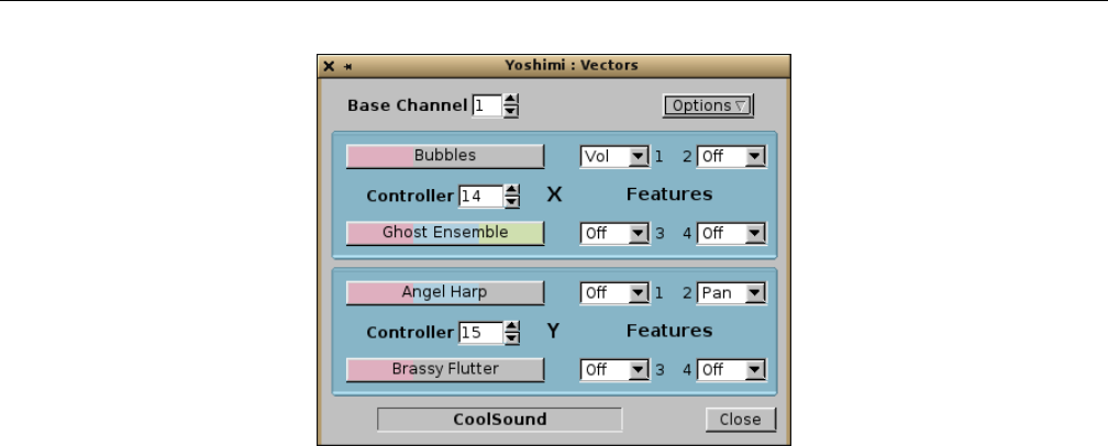
Yoshimi Software Synthesizer 16.2 Vector Dialogs
Figure 152: Yoshimi Vectors Dialog
The user-interface items in the vector dialog are:
1. Top Line
1. Base Channel
2. Options
2. X Vector
1. Controller (CC Event)
2. Part 1
3. Part 2
4. Features
1. Feature 1 (Volume)
2. Feature 2 (Pan)
3. Feature 3 (Brightness)
4. Feature 4 (Modulation)
3. Y Vector
1. Controller (CC Event)
2. Part 1
3. Part 2
4. Features
1. Feature 1 (Volume)
2. Feature 2 (Pan)
3. Feature 3 (Brightness)
4. Feature 4 (Modulation)
4. Bottom Line
1. Vector Name
2. Close
Although they are nested, for simplicity we will discuss the unique items serially.
1. Base Channel. Vector Base Channel. This item specifies the MIDI channel on which the vector (of
parts) will be based. This channel is the incoming MIDI channel to which the vector setup will respond
to on all parts.
Values: 1 to 16, 1*
196
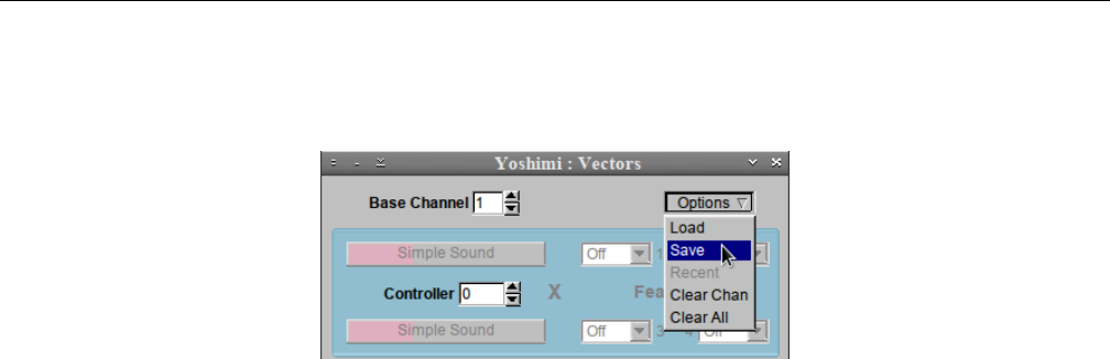
Yoshimi Software Synthesizer 16.2 Vector Dialogs
2. Options. Vector Options.
Values: 1 to 127, 64*
Figure 153: Yoshimi Vectors Options
The menu entries provide the actions described in this list:
1. Load. Brings up a file dialog that let’s one pick an arbitary vector file (extension .xvy) in an
arbitrary directory, or select a ”Favorites” directory in which to look for vector files. The base name
of the file is then shown in the Vector Name field. This field is also user-editable, and is stored
when the settings are saved.
2. Save. Brings up a file dialog that let’s one save an arbitary vector file (extension .xvy) in an
arbitrary directory, or select a ”Favorites” directory in which to save a vector file. The base name
of the file is then shown in the Vector Name field.
3. Recent. Brings up a short list of the previous vector files dealt with.
4. Clear Chan. Clears the base channel number????
5. Clear All. Clears out the full vector setup, rendering it an ”empty” vector setup that cannot be
saved.
Note that loading vectors is a ’soft’ load. It first runs down the overall volume (over about 100 ms),
then mutes the whole synth before performing the load operation. Only when that is complete does it
unmute the synth. (Note that soft loading also applies to patch sets, but not to instrument patches.)
3. X Vector. The X Vector. This vector provides the minimal setup for a vector. This setup requires
Yoshimi to be configured for 32 parts, to be able to fully support a two-part vector for every MIDI channel.
This section is disabled until selects a Controller event value for it.
4. Controller. Vector Controller CC Event. If 0, the section (Xor Y) that this value is in is disabled.
Otherwise, the number is the MIDI continuous controller (CC) event value that is to be used to control
the mix of the two parts involved in this vector.
Values: 1 to 119, 0*
5. Part 1. Part 1. The top button in the section (Xor Y) selects the first part to use in the two-part
vector. Clicking this button brings up the default bank dialog. This dialog allows one to select a part
(instrument), or to select an different bank from which to choose a part (instrument).
6. Part 2. Part 2. The bottom button in the section (Xor Y) selects the second part to use in the
two-part vector. Clicking this button brings up the default bank dialog, just as for the Part 1 button.
7. Feature 1. Vector Feature 1, Volume. This feature can be disabled, or enabled. Feature 1 is always
fixed as MIDI event 7 (volume), and is not reversible. When enabled, the volume is traded off between
the first part and second part as the selected MIDI CC controller event data value changes. While the
first part increases in volume, the second part decrease in volume, and vice versa.
197
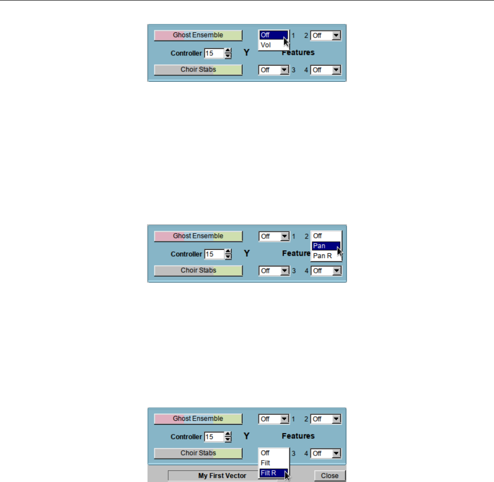
Yoshimi Software Synthesizer 16.2 Vector Dialogs
Figure 154: Yoshimi Vectors, Feature 1
Values: Off*, Vol
Note that the common theme between all features is that they apply inversely to the two parts/instruments
that are paired in an Xor Yvector.
8. Feature 2. Vector Feature 2, Pan. This feature can be disabled, enabled, or reversed. When enabled,
it acts similarly to volume, panning from left to right as the data value increases. When reversed, it pans
from right to left as the data value increases.
Figure 155: Yoshimi Vectors, Feature 2
Values: Off*, Pan, Pan R
9. Feature 3. Vector Feature 3, Brightness. Brightness here refers to the application of a (we presume)
low-pass filter with a varying cutoff frequency. This feature can be disabled, enabled, or reversed. When
enabled, it acts similarly to volume, changing the brightness from left to right as the data value increases.
When reversed, it changes the brightness from right to left as the data value increases.
Figure 156: Yoshimi Vectors, Feature 3
Values: Off*, Filt, Filt R
10. Feature 4. Vector Feature 4, Modulation. Modulation here refers to the application of an (we
presume) LFO (for amplitude or frequency) with a varying modulation depth. This feature can be disabled,
enabled, or reversed. When enabled, it acts similarly to volume, changing the modulation from left to
right as the data value increases. When reversed, it changes the modulation from right to left as the data
value increases.
198
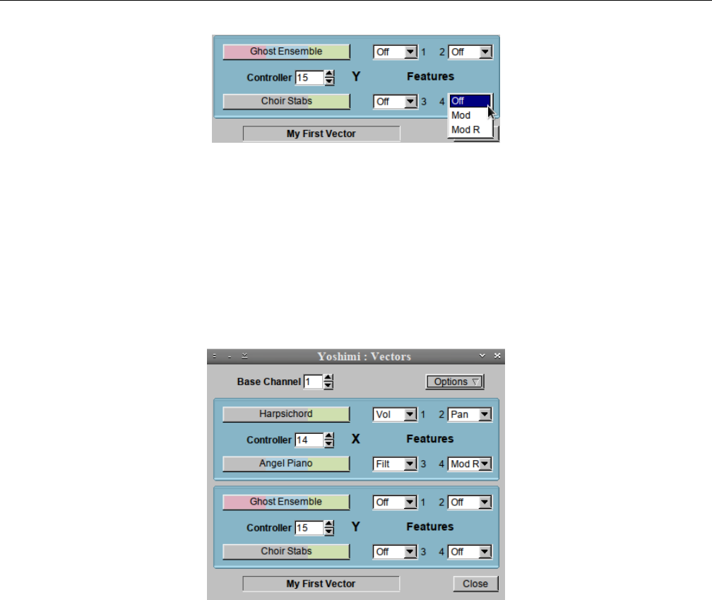
Yoshimi Software Synthesizer 16.2 Vector Dialogs
Figure 157: Yoshimi Vectors, Feature 4
Values: Off*, Mod, Mod R
11. X Vector. The X Vector. This vector provides the maximal setup for a vector. This setup requires
Yoshimi to be configured for 64 parts, to be able to fully support an additional two-part vector for every
MIDI channel. This section is disabled until selects a Controller event value for it.
Other than that, the Yvector acts like the Xvector, and all of the sub-items have the same func-
tionality as in the Xvector.
Figure 158: Yoshimi Vectors Saved as ”My First Vector”
If starting a new vector setup, first select the base channel (1 to 16) to set the vector on. Next, use
the Xand Y Controller spin-boxes to select the incoming CC. If you set an invalid one strange things
may happen, though it won’t actually do any harm.
The instrument buttons bring up the instrument list window in exactly the same way as the main
part one does, but do not currently the right-click windows return feature.
When setting up a completely new vector, if the mixer or the main part are visible, they may be
slightly out of sync, but will correct themselves as soon as one changes an instrument or part.
When one clears a vector it doesn’t delete loaded voices, nor does it change the active status of the
part, nor the number of parts available. This is because these settings may have been made independent
of vector control. In short, vector setup will add things but not remove them.
12. Vector Name. From version 1.5.3 on, the vector name is now editable in the same way as an
instrument name is, and it is stored along with all the other data. This is particularly relevant when it is
saved in a patch set. When reloading, one will know what the vector is called; previously, the name was
lost.
199

Yoshimi Software Synthesizer 16.3 Vector / Vector Control
16.3 Vector / Vector Control
Setting up vector control via MIDI is currently done as follows. In the required channel send:
•NRPN MSB (99) set to 64
•NRPN LSB (98) set to 1 [8192]
•Data MSB (6) set mode:
–0 = X sweep CC
–1 = Y sweep CC
–2 = enable X features
–3 = enable Y features
–4 = x1 instrument (optional)
–5 = x2 instrument (optional)
–6 = y1 instrument (optional)
–7 = y2 instrument (optional)
Setting CC for X enables vector control; any value outside the above list disables it.
Data LSB (38) value to set features:
•1 = Volume (fixed)
•2 = Pan (the default)
•4 = Filter Cutoff (Brightness, it is the default)
•8 = Mod Wheel (the default)
•0x12 = 18 = Reversed Pan
•0x24 = 36 = Reversed Filter Cutoff
•0x48 = 72 = Reversed Mod Wheel
The feature numbers are chosen so they can be combined. So, 5 would be Volume + Brightness and
19 would be Volume + Reversed Pan.
Setting the sweep CC for the X axis enables vector control. It also sets, but doesn’t enable the default
X axis features. Setting the sweep CC for the Y axis sets, but doesn’t enable the default Y axis features.
If one doesn’t enable any features, not a lot will happen.
The feature numbers are chosen so they can be combined. So, 5 would be Volume + Brightness and
19 would be Volume + Reversed Pan.
Optional settings. The first part, the number, is the MSB value. The second part is the LSB, the
parameter value to set. Note that the instrument IDs are for instruments in the current bank.
•4 = x1 instrument ID
•5 = x2 instrument ID
•6 = y1 instrument ID
•7 = y2 instrument ID
•8 = set CC for X feature 2
•9 = set CC for X feature 4
•10 = set CC for X feature 8
•11 = set CC for Y feature 2
200

Yoshimi Software Synthesizer 16.4 Vector / Command Line
•12 = set CC for Y feature 4
•13 = set CC for Y feature 8
The IDs are for instruments in the current bank. Any data MSB value outside the above list disables
vector control. Sweep CCs and feature CCs are sanity-checked.
An Example. From channel 1, send the following CCs:
CC Value
99 64
98 1
6 0
38 14
98 1 *
6 1
38 15
98 1 *
6 2
38 1
98 1 *
6 3
38 2
This sequence will set up CC 14 as the X axis incoming controller, and CC 15 as the Y axis incoming
controller, with X set to volume control and Y set to pan control.
One can either go on with the NRPNs to set the instruments (this will load and enable instruments
from the current bank), or enable and load them by hand. For channel 1 this would be part 1 and 17 for
X and part 33 and 49 for Y.
The (*) CCs ensure that the data bytes are reset each time. This is not really necessary for the earlier
commands, but should be done if one sets the instruments with NRPNs as well, otherwise one will try to
set them twice.
16.4 Vector / Command Line
This section covers material that could be in the command-line section (see Section 18 ”The Yoshimi
Command-Line Interface” on page 209), but is really too detailed to cover there. The examples here, to
set up vectors from the command line, are provided by Will.
Assuming we want just a single axis on channel 1 (which is channel 2 in the GUI), first we need to
make sure we have enough parts available:
yoshimi> set available 32
Available parts set to 32
The next command must aways be the first command, as everthing else depends on it. It’s the
command that enables vector control. The xtoken denotes the ”x axis”, and the cc token, followed by
14, is the incoming sweep CC (control change) that will vary the features one sets.
201

Yoshimi Software Synthesizer 16.4 Vector / Command Line
yoshimi > set vector 1 x cc 14
Vector channel set to 1
Note that, according to the list of MIDI CC’s at http://nickfever.com/music/midi-cc-list, CC
14 is undefined, normally. It is thus available for Yoshimi to assign for its own purpose.
There are four vector features currently available:
•1is fixed as volume.
•2is pan by default.
•3is brightness by default.
•4is modulation by default.
We will select volume for this example. Let’s enable this feature:
yoshimi Vect Ch 1 X > set features 1 enable
Set X features 1 en
Next, one needs to set the instruments that will be used. The instruments can only be selected
from the instruments in the current bank. Therefore, assuming the current bank is the ”Will Godfrey
Companion”, let’s set up two instruments:
yoshimi Vect Ch 1 X > set program left 20
Loaded 20 "Bubbles" to Part 1
yoshimi Vect Ch 1 X > set program right 120
Loaded 120 "Ghost Ensemble" to Part 16
The left token merely assigns instrument 20 to a ”virtual” left side of the X axis, and the right
token assigns instrument 20 to a ”virtual” right side of the X axis.
(Chris asks: How did the part numbers 1 and 16 come about? What are the rules? Why are 32 parts
needed, if only 1 to 16 are involved? Why do we need to have 64 parts when we add the Y axis below?
Can we set intermediate values between ”left” and ”right” and ”up” and ”down” to get some really weird
morphs?)
If one now sweeps the the controller assigned to CC 14, the sound will morph between these two
instruments.
To continue on to using the other axis as well, one needs to have 64 parts available:
yoshimi Vect Ch 1 X > /set available 64
Available parts set to 64
Note the slash, which lets the user immediately access the topmost command level, where the ”avail-
able parts” setting can be performed. Then:
yoshimi > set vector y cc 15
Vector 1 Y CC set to 15
This command sets up the Y axis to be controlled by MIDI CC 15, which is, again, a CC that is
normally undefined. We will use panning (feature 2) for this vector, which is defined on the Y axis:
202

Yoshimi Software Synthesizer
yoshimi Vect Ch 1 Y > set features 2 enable
Set Y features 2 en
Analogous to the ”left” and ”right” virtual directions used above for the X axis, the Y axis used the
”up” and ”down” virtual directions:
yoshimi Vect Ch 1 Y > set program down 107
Loaded 107 "Angel Harp" to Part 32
yoshimi Vect Ch 1 Y > set program up 78
Loaded 78 "Brassy Flutter" to Part 48
Notice that the directions left, right, up, and down match the directions provided by a traditional
joystick.
So we have now set up a vector sound where MIDI CC 14 morphs the sound through a continuous
linear combination of two different instruments, and MIDI CC 15 morphs the sound between two other
instruments. One can then save one’s cool vector sound to a file:
yoshimi Vect Ch 1 Y > save vector CoolSound
Saved channel 1 Vector to CoolSound
The file extension for the save vector sound file is .xvy, and this extension is added automatically.
The final name of the file is CoolSound.xvy.
(Chris asks: Where is this file saved? Is there a way to modify this location?)
At any time one can reload this vector sound file from the command-line:
yoshimi> load vector channel 0 CoolSound
Loaded Vector CoolSound to channel 0
If there is no channel number provided, then the vector sound will be loaded to the same channel as
it was saved from:
yoshimi> load vector CoolSound
Loaded Vector CoolSound to source channel
17 MIDI Learn
In this section, we show how to use the new (with 1.5.0) MIDI Learn feature of Yoshimi. MIDI Learn
is a method to remotely control many parameters in an audio/MIDI application via a MIDI controller.
Each parameter that is ”learned” can be controlled, and the setting changes recorded.
17.1 MIDI Learn / Basics
In Yoshimi’s direct-access system, MIDI Learn is available, to the extent that it can handle controls that
have a range of 0 to 127.
203
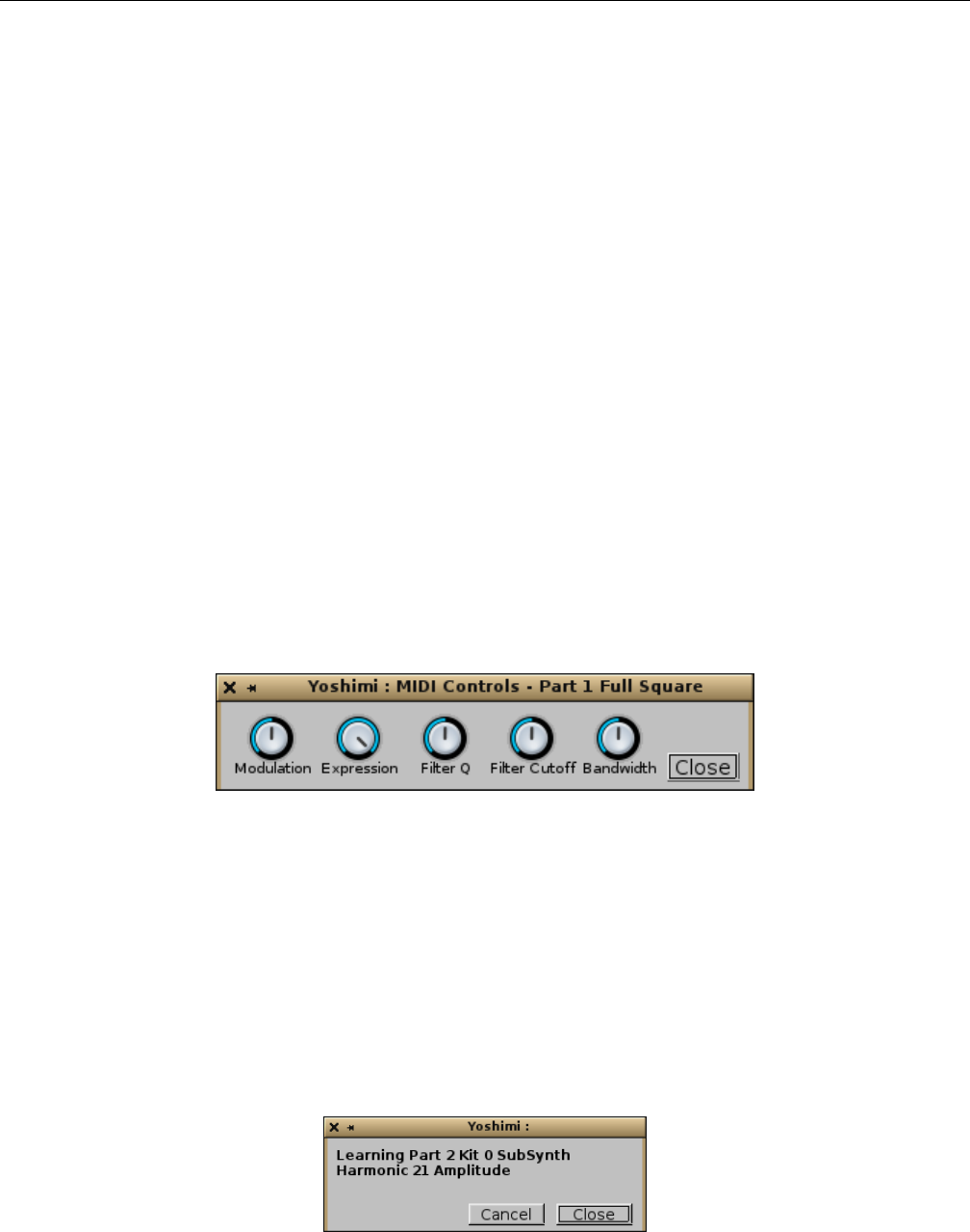
Yoshimi Software Synthesizer 17.2 MIDI Learn / User Interface
One can have multiple controls on the same CC. But, although they all work, only the last one
updates the user inteface. They are channel specific. So if one is rich enough to have two MIDI keyboards,
one can set them up to do quite different jobs. Some of the controls, like volume and pan, are immediate,
but most are ”next note”.
In order to unset a learned value, simply delete the line.
Some external controllers use the pitch wheel control per-channel for up to 16 high-resolution faders.
Some synthesizers send a number of high resolution controllers as NRPNs. Yoshimi MIDI Learn can
handle these. The controls that can actually benefit from better resolution are most of the volume and
detune ones. They are learned in exactly the same way as ordinary CCs, but instead of presenting a line
that includes an editable CC field, they show a non-editable hexadecimal number with a space between
the bytes and followed by an ”h”, such as 0a 2c h. Also, these lines default to having Block set. See
that item’s discussion below.
Now Yoshimi can respond to aftertouch. One might wonder why one would want to MIDI-learn
modulation when there is already a dedicated CC for it; and the same for ”brightness”. The answer is
that there is currently no way to link these to aftertouch, and this is especially relevant for people using
wind controllers. MIDI Learn sees aftertouch as CC 129 (via a sneaky conversion). This has another nice
result. If one does not have an aftertouch device currently in hand, use any other controller; then, in the
editing window, just change the controller number to 129. Save the learned set, and next time one does
have such a device, just load the file and off you go! MIDI Learn can emulate the MOD wheel, as it is
an accessible control in the little panel brought up when one right-clicks the Controllers button in the
bottom panel of the Yoshimi main window: One can use it for any volume or pan, and can have a lot of
fun with things like the Phaser effect as these are all ”instant”. The Mod wheel is seen as CC 130.
Figure 159: MIDI Controls Panel
The emulated MIDI controls are: Modulation,Expression,Filter Q,Filter Cutoff, and Master
Bandwidth.
17.2 MIDI Learn / User Interface
To activate MIDI Learn, Ctrl-right-click on any user interface control. A pop-up window will detail
the control selected, or indicate that the control is not learnable. A message will also appear in the console
window or command-line interface (if active).
Figure 160: MIDI Learn Prompt Example 1
204
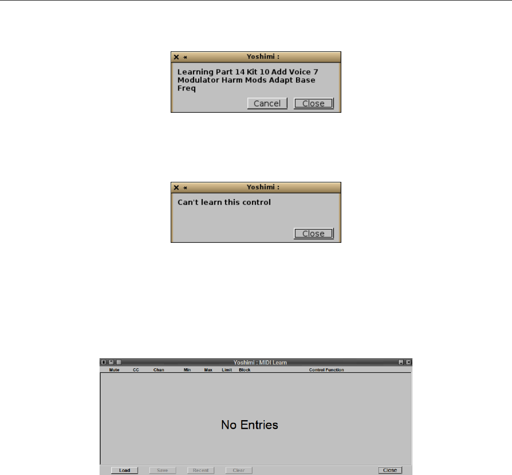
Yoshimi Software Synthesizer 17.2 MIDI Learn / User Interface
Here is another example:
Figure 161: MIDI Learn Prompt Example 2
If a Yoshimi control is not MIDI-learnable, a message pop-up will indicate that it is not learnable:
Figure 162: MIDI Learn Prompt Unsupported Example
Note that the majority of controls, including the sliders, are MIDI learnable. However, note that, for
sliders to be learned, one must click on the track of the slider, not the thumb of the slider.
If the Yoshimi / MIDI Learn... option is selected, and there are no MIDI-learn entries available yet,
then the following empty dialog appears:
Figure 163: Empty MIDI Learn Dialog
A message will also appear in the console window/CLI.
After turning on learn, the first physical controller moved, or CC message sent, will be locked in, and
one will see the user-interface knob or slider move in synchrony with the physical control. The pop-up
window will disappear, and the console message Learned appears, with a line underneath with exactly
what control was caught.
There is also an activity ”LED” between Chan and Min indicators that flickers when the associated
CC or channel is received, provided the line is not muted, or blocked by an earlier one.
One can stack up message lines that have the same CC and channel, so that a single incoming can
change a part volume and at the same time change the filter cutoff and with a third line change the
panning of a different part.
Multiple lines will always be displayed (and actioned) in ascending order of CC, then channel number
205
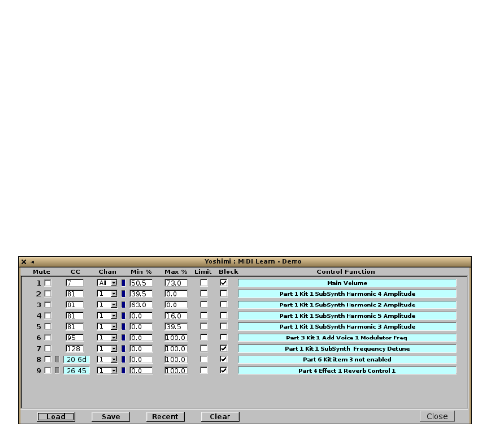
Yoshimi Software Synthesizer 17.2 MIDI Learn / User Interface
For a quick example, on our system we’re running only ALSA. So we plug a Korg NanoKEY2 mini-
USB keyboard in. We determine the existing ports using
$ aconnect -i -o
We see that we have (among other ports) client 24:0 is the nanoKEY2 MIDI keyboard, and Yoshimi
at client 129:0. We connect it to Yoshimi using
$ aconnect 24:0 129:0
We ctrl-right-click on Yoshimi’s Velocity Sense knob in the main window, then we click on the
MOD button on the nanoKEY2, and we see an entry CC=1, Chan=1, Min=0, Max=127, and control
function name of ”Part 1 Vel Sens”. Every time we press the MOD button on the nanoKEY2, we see the
”LED” appear, and movement in Yoshimi’s Velocity Sense knob.
Once entries have been added, a fully-fleshed list of learned items is presented if one then uses the
MIDI Learn menu entry; one will see a new window displaying the recently-learned controller. Along with
a number of settings, one sees text with precise details of this complete action.
Figure 164: MIDI Learn Dialog
If the controller learned was an NRPN, this dialog will show a hexadecimal number in the CC field,
and this item will not be editable. Notice that a small indented button will appear between the mute
status and the NRPN value. If this it clicked on it will turn red indicating that it is now a 7 bit value.
This is type of range is sent by some hardware synths and controllers.
Adding or deleting rows in this dialog, or changing the CC or channel number, will cause the rows
to be sorted again. The maximum number of MIDI-Learned lines is 200.
The major items of this dialog are the editor settings available:
1. Mute
2. CC
3. Chan
4. Min
5. Max
6. Limit
206

Yoshimi Software Synthesizer 17.2 MIDI Learn / User Interface
7. Block
8. Control Function
9. Load
10. Save
11. Recent
12. Clear
Now use the Yoshimi drop-down menu and click on Midi Learn, to see a new window displaying
the recently-learned controller. Along with a number of settings, it shows text with precise details of this
complete action.
Also shown is an activity LED that flickers when the associated CC/channel is received.
1. Mute. Mute. Disables the MIDI Learn control specified by the corresponding line of settings. The
control is still available, but will not be in effect.
Values: Checked, Unchecked
2. CC. CC. Incoming CC. Provides the value of the controller that is learned. For example, a value of 7
indicates that the control value affects the main volume of Yoshimi. Note that NRPNs are not included.
Also note that CC has no default values; the values are whatever the incoming learned values are.
Values: 1 to 127
3. Chan. Chan. Incoming channel number. Note that, in the MIDI Learn window, the channel
numbers start from 1, as do all the other numbers in that window except controllers, which start from 0,
following MIDI convention. Also note that the channel has no default values; the values are whatever the
incoming learned values are.
Values: 1 to 16, and All
4. Min/Max. Min and Max. Provides the minimum and maximum incoming values for the controller
value. Since V 1.5.2 this is shown as a percentage with a resolution of 0.5 If Min is greater than Max,
this reverses the control direction. If Min is equal to Max, it becomes a threshold setting. Any value
lower than this threshold will be passed on as 0, and any value higher will be passed on as 127. These
values will then be translated to the Min and Max of whatever controller has been linked. Thus, for
a simple switch those values will be 0 (off) and 1 (on). For most controls it will be 0 and 127. For an
Addsynth modulator it will be OFF and PWM.
Bear in mind that Min and Max are percentage values, not 0-to-127 MIDI values. Divide the incom-
ing MIDI value by 1.27 to get the percentage value. The resolution is to the nearest 0.5. To summarize:
1. In MIDI Learn, set both Min and Max to the same percentage value. Call it ”M%”.
2. Multiply M% by 1.27, and increase the result up to the next integer value.
For example, if M% = 90.0, any MIDI value ≤115 will turn a switch off, and any value >115 will
turn it on.
Values: 0 * (min) to 100 * (max)
5. Limit. Limit/Compression switch. Limiter versus compression. The Min/Max range can either be in
the style of a limiter or a compression. Set to limit, the Min and Max will be hard cutoffs. For example,
if Min is 20 and the incoming value is 5, then the result is 20.
Set to compress, the incoming value will be converted to fit the range. For example, if Min is 32,
Max is 95, then an incoming value of 0 will be 32, an incoming value of 2 will be 33, etc.
207

Yoshimi Software Synthesizer 17.2 MIDI Learn / User Interface
Values: Checked (Limit), Unchecked (Compress)
6. Block. Block. Specifies blocking of all later actions on the same CC/channel pair (including system
ones). If a loaded set refers to Yoshimi controls that are disabled, or don’t exist, such controls will be
ignored. The block feature will be active unless the line is muted.
Values: Checked, Unchecked
For devices that send high resolution controllers as NRPNs. Also, these lines default to having Block
set. This is so that the NRPN is not passed on to Yoshimi, which would result in ”go away” messages or
obscure actions. However, like ordinary CCs, they will stack and one can set several lines with the same
NRPN performing mutiple actions, and then unblock all but the last one.
The way this fits in with the rest is that the incoming data values are combined as a 14 bit number,
then (as a floating point number) divided by 128 so the overall range is exactly the same as normal CCs.
However, when decoded for various controls *all* CCs are converted by a second (hidden) set of limits to
get the maximum possible resolution:
•Humanise: 0 to 50
•Engine fine detunes: -8192 to 8191
•Engine coarse detunes: -64 to 63
•LFO frequency: 0.0 to 1.0 (float)
The actual resolution is determined by the physical control source. Most controls seem to be 10 bit,
but if generated within an automation source, one will get the full 14 bits.
7. Control Function. Control function. Provides text describing what control is affected, or if the
part is disabled or not.
One can delete any existing MIDI Learn via Ctrl-right-click on the Control Function text for
that line. One is then presented with a confirmation message giving the line number and the text as a
reminder. Adding lines, or changing either CC or channel numbers, will re-order the lines. Deleting lines
will cause a redraw, but not a re-sort. Changing the CC or channel will only do a re-sort when necessary,
as when the new number is now higher or lower than the adjacent ones.
The same CC/controller can be used to change several different internal Yoshimi controls. For ex-
ample, one can have a part’s volume being changed while another part is having an effect level changed.
This is done by selecting one part, and making a setting with the desired controller, and then selecting
another part, and making a setting with the same controller. This single controller will then affect both
parts at once.
8. Load. Load. Loads a set of MIDI Learn values from a file. The extension of the file is .xly. If
a loaded set refers to Yoshimi controls that are disabled, or don’t exist, those controls will be ignored.
However the Block feature will still be active, unless the line is muted.
9. Save. Save. A complete list of MIDI Learn values will be saved by clicking on the Save button; one
then sees the usual file-chooser window. The file is saved where desired, with the extension .xly,
10. Recent. Recent. This button is used for loading a set of MIDI Learn values from the recent history.
11. Clear. Clear. This button clears the entire learned list from the MIDI Learn dialog.
208

Yoshimi Software Synthesizer 17.3 MIDI Learn / Tutorial
17.3 MIDI Learn / Tutorial
This mini-tutorial is courtesy of Will.
Say one has a foot pedal that outputs CC values on the standard volume, CC 7. Now this is per
channel, so only instruments on the first channel will pick it up. This presents a problem if one has
automation/backing tracks on other channels and one wants to keep everything together. So here is what
to do:
While holding down Ctrl, right-click on the Volume knob at the top of the main window. A window
will open with the message ”Learning Main Volume”. If one now operates the foot pedal, the window will
disappear and one will see that the main volume control is now responding to the foot pedal.
However, this means one is changing both the main volume and the part 1 volume at the same time.
So now open the MIDI learn window via the Yoshimi drop-down menu. One will see that it now has
a line detailing the incoming CC and channel, along with other controls and the control function named
Main Volume. Click on the Block check box, and one will see that the part 1 volume control no longer
responds.
Now the foot pedal will control only the master volume, not the individual part volumes. This setup
will survive loading new patch sets, and also a main reset (while still running).
It’s quite likely that the foot pedal will go from 0 to 127, when one actually wants a much smaller
control range. In that case, one can change the Min and Max values to (for example) 40 and 90. In this
way, the entire range of the pedal control will be reduced linearly to 40-90.
If one sets the Limit checkbox, then these values will instead be cutoff points so anything from the
pedal between 0 and 40 will be 40, and anything between 90 and 127 will be 90
To temporarily disable this controller line, use the Mute checkbox. The entire line will be greyed,
and as the Block is no longer active normal part volume control will be restored.
A point that is not obvious is that although incoming CCs are per-channel, the actions are per-part,
so if one sets controller 94 for part 1 volume and then set it again for part 2 volume, one gets two lines,
each controlling just one part but acting together. Change the Min and Max of one of them to 127 and
0 respectively and one will increase in volume while the other reduces.
Volume, pan, and most of the effects are immediate, while most of the other controls start on the
next note. Eventually I want to get LFOs, filters etc. to be immediate, but that’s for another release!
18 The Yoshimi Command-Line Interface
Yoshimi provides a command-line mode of operation where most aspects of the application can be con-
trolled via text commands. This mode is useful for blind people, those with motor control problems and
for programmers, for example. These text commands can be put into a script file, and that script can
then be run.
To access the command-line mode, add the -i or --no-gui command-line option when starting
Yoshimi on the command-line. But note that, when starting Yoshimi on the command-line without the
”no gui” option, the ”command-line” mode of operation is available at the same time as the GUI, as well.
One of the main features of recent Yoshimi releases is improved non-GUI accessibility. In fact, Yoshimi
can run with neither GUI nor CLI input access. Working purely as a hidden MIDI device, a daemon of
sorts. To enable a tidy close, there is a new short-form NRPN. Just send 68 to both MSB and LSB (CC99
and CC98).
209

Yoshimi Software Synthesizer 18.1 Command Depth
In a command line environment, almost all the ’running’ commands are available, and now all of the
instrument editing ones are available. Also, the whole of vector control, and MIDI-learn, is also exposed
to the command line.
One can decide what MIDI/audio setup is wanted, list and set roots and banks, load instruments into
any part, change a part’s channel, set main volume and key shift, and set up vector control. A number of
first-time defaults have been changed to make this feature easier.
When starting from the command line, an argument can be included for a new root path to be defined
to point to a set of banks fetched from elsewhere. This will be given the next free ID. A future upgrade
will allow the ID to be set to any valid one when it is created, mirroring the GUI behaviour.
Once running, almost all configuration can be done within the terminal window. There is also ex-
tensive control of roots, banks, parts and instruments including the ability to list and set all of these.
Additional controls that are frequently taken for granted in the GUI, but otherwise get forgotten, are
master key shift and master volume.
The command-line mode provides extensive error checking and feedback. Note the change in nomen-
clature from ”Parameters” to ”Patch Set”, which is visible in the main screen, and also reflected in
the command line. The prompt will always show what command level one is on, along with relevant
information.
18.1 Command Depth
Recent developments in Yoshimi have made it possible to greatly (one could say dramatically) extend
command-line access deep into the synth structures. This creates a problem where the command line itself
could become unmanageably long. Thus, now only the current context level is printed in full. The levels
higher up the tree are minimized:
yoshimi Part 1+>
yoshimi P1+, Sub>
yoshimi P1+, Sub+>
yoshimi P1+, S+, Filter analog>
Rather than stating that a switch is on or off, there is now just a +sign for ”on”, and nothing for
”off”. This is clearer than using a -, and the slight shift in the line gives the user another visual clue.
There is a new command in the ”config” context that controls where this is displayed, or whether it
is shown at all. This command is:
EXPose {OFF, ON, PRompt}
Off will give the bare prompt with no other information. On shows it as a separate line above the
prompt:
@ P1+, S+, Filter analog
yoshimi>
Prompt shows it as a part of the prompt:
yoshimi P1+, S+, Filter analog>
210

Yoshimi Software Synthesizer 18.1 Command Depth
The default setting is ON.
At the CLI prompt, when effects are being managed, the preset number is also shown on the prompt
so you’ll typically see something like:
yoshimi p2+ eff 1 reverb-1 >
One will also get a confirmation message. Here is an example session:
Starting from the yoshimi prompt:
yoshimi> s p 2 on
Main Part Number 2
Part 2 Enable Value 1
yoshimi part 2+ > s pr 107
Loaded Smooth Guitar to Part 2
yoshimi part 2+ >
This command sets part number 2 to program number 107 from the current instrument bank.
Yoshimi is now on part 2 as the current part (indicated by the prompt), and all subsequent commands
will relate to this ”level”. At this level, one can change the current part simply with:
yoshimi part 2+ > s 4 on
yoshimi part 4+ >
For clarity we ommit the confirmation messages from here on.
Yoshimi is now on part number 4. Now set an effect:
yoshimi part 4+ > s ef re
yoshimi p4+ eff 1 reverb-1 >
This command sets the part’s effect 1 (implicit) to the reverb type.
Note that many settings parameters are optional, and if omitted, either a default or last-used value
will be assumed. Also, names are truncated to 6 characters so the prompt line doesn’t get unmanageably
long. From here you can set a preset for this effect:
yoshimi 4+ eff 1 reverb > s pre 3
Since V 1.5.0 the presets have been shown in the prompt, and one will still get a confirmation
message. Also, it used to be necessary to enter type for an effect but since V 1.5.10 the name is entered
directly.
Settings that follow in a direct command ”path” through several levels can be made all at once, and
one will be left at the appropriate level. Thus, summarizing some of the above commands:
yoshimi part 4+ > s ef 2 re
yoshimi p4+ eff 2 reverb >
One cannot combine type and preset as they are both at the same level.
To go back one level, use the ”..” command (reminiscent of the cd .. operation in an OS command
shell):
211

Yoshimi Software Synthesizer 18.1 Command Depth
yoshimi p4+ eff 2 reverb > ..
yoshimi part 4+ >
To go back to the top command level, use the ”/” command:
yoshimi part 4 > /
yoshimi >
These two special level-movement commands can also be put on the front of any other command.
Starting where we were before:
yoshimi p4+ eff 2 reverb > .. s vol 70
yoshimi part 4+ >
Part 4 volume is now at 70, and Yoshimi is once again at the ”part level”, not the ”part FX level”.
The help menus and lists are also partially context sensitive. This feature should help avoid clutter
and confusion.
As well as an immediate history, Yoshimi maintains a single command history file for all instances of
Yoshimi that records any non-duplicated loads or save. Thus, provided one makes a normal command-line
exit, the last commands will be available on the next run of Yoshimi. The command-line now has formal
methods of opening, selecting and closing additional instances.
When loading external files from the command line, there is an alternative to entering the full name
if Yoshimi has already seen this file and it is in the history list. In this situation you enter ’@’ followed
by the list number.
yoshimi> l h v
Recent Vectors:
1 /home/will/another.xvy
2 /home/will/Subtle.xvy
3 /home/will/excellent.xvy
4 /home/will/yoshimi-code/examples/CoolSound.xvy
yoshimi> lo ve @4
Main Vector Loaded /home/will/yoshimi-code/examples/CoolSound.xvy to chan 1
The loading of externally-saved instruments is also done, by default, relative to one’s Yoshimi home
directory. However, saving an external instrument from the command-line still requires a full pathname.
The ’recent history’ lists can load MIDI-learned files, patchsets, or vector files numerically from the
associated list, instead of having to type the names out. This uses the ’@’ (list number) operator.
Commands with ”*” in the description need the setup to be saved, and Yoshimi restarted to be
activated.
Note that Yoshimi’s command-line can also load and save states, patchsets, and scales, and can list
recent histories. Vector load and save is also supported from the command-line. That’s a complete vector
set, with all mappings, instruments, etc. One can independently decide which channel to load and save
from, so that one can actually build up a vector set in (say) channel 3, then later decide to use it in
212

Yoshimi Software Synthesizer 18.2 Command Level
channel 7. It has the extension .xvy, standing for ”Xml/Vector/Yoshimi”. It will eventually be integrated
with the saved states.
Another small detail is that all of the minimum command-line abbreviations are now Capitalised in
the help lists.
A few more features will be added, and the organisation of them may be adjusted slightly. If any
configuration settings are changed, either at the command-line or in the graphical user-interface, one will
be given a warning when exiting, with the option to continue running so one can save the changes.
18.2 Command Level
A command level (also known as a ”context level”) is simply a position in the hierarchy of commands
that cover some aspect of Yoshimi functionality. The major levels are:
•Top Level
•System Effects
•Insertion Effects
•Part
•Part Effects
•Scales (microtonal)
•Vector
•Controllers
•Synth Engines
– Addsynth
– Addsynth Voice
– Subsynth
– Padsynth Harmonics
– Padsynth Envelopes
Any level that has direct numerical content can be changed with ”set (n)” once at that level. The
level is indicated by the text in the Yoshimi prompt. For example, one can set 1 to 16 vector channels, so,
from the Top level, the following command will set the default (1, or the last-used number). The second
command will, given this level (the Vector level), switch to vector channel 5. However, at the start, one
could have gone straight to 5 with the third command.
set vector # or "s ve"; sets the context
set 5 # or "s 5"
set vector 5 # or "s ve 5"; quicker!
A detailed discussion of command-line vector control is presented in Section 16.4 ”Vector / Command
Line” on page 201.
18.3 Command Scripts
Yoshimi command-line users can run plain-text scripts that behave in exactly the same way as if the
commands had been entered from the command-line directly. The actual script command can be initiated
from any context/level and is simply:
213

Yoshimi Software Synthesizer 18.3 Command Scripts
RUN {filepath-of-script}
To avoid confusion, the script routine first sets the context to the top level, then performs all the
commands, following context level changes. If there is a fault in the script, it will be reported along with
the number of the line where the error occurred. Due to the buffering used, the script will return before
many of the actions have actually taken place. Therefore an error report is likely to be some way up the
responses. Typically it will be something like:
*** Error: Which Operation? @ line 13 ***
Here is a simple example:
# A script test
set part on
# These two lines are spaced in a bit
set add on
set voice on
set volume 45
This script makes sure the part is on, that the relative addsynth and voice are on, and finally sets its
volume to 45.
Although this process starts from the top level, it will use the parameters that were last set. Thus, if
one had been working on part 7, addsynth voice 2, then that is the one that will have its volume adjusted.
This means one can set up generic preferences, then apply them to any part, engine, etc.
The script routine honors any normal abbreviations. Blank lines are ignored. A ’#’ at the start of a
line marks it as a comment so will also be ignored. However, both of these kinds of lines will be in the
line count if an error is reported.
Buffering can also cause commands to go out of sequence if a buffered one is immediately followed
by a related direct one. For this reason there is an extra command specific to scripts:
WAIT [n]
The command must be entered in full, and the range is 1 to 1000 milliseconds. In the example below,
switching the kit mode is buffered but setting a kit item isn’t, so without a delay the setting would be
attempted before it was available. A 20ms wait seems to be enough of a delay in this case.
# Using delays
sp1on
s add off
..
s mul
wait 20
s 5
s on
s sub on
214

Yoshimi Software Synthesizer 18.4 Other Command Tables
18.4 Other Command Tables
When running from the command line, commands can be entered after the ’up and running’ message.
Commands are not case-sensitive. Commands can be abbreviated to the first three letters of each com-
mand, or, in some cases, just one letter. This is indicated by uppercase letters in command descriptions.
The commands available depend on the current ”context” of the command line. However, there is a group
of commands always available:
•?or help
•List
•RESet
•EXit
Apart from these commands, the command line works on a system of context levels, and normally
only the commands relevant to that ”level” will be available.
We describe the command lists here. These lists are relative to a particular context, and what one
sees if one enters ?while at that level, to get help. However the command lists can all be called specifically
from any level. From any higher level, ? ? will show the top level one.
18.4.1 Top Commands
These commands are part of the Top context/command level. First, one gets the default options, always
available. Then there are several options that have ellipsis (...); these are the context submenus. After
that come all the actual top level controls; there are still a lot!
yoshimi> ?
Note that there are a number of commands common to all command levels. We describe them here.
Table 2: Yoshimi Common Commands
?, Help Show commands. Also note specialized versions such as ?
list.
STop All sound off. Stop! Panic!
RESet Return to start-up conditions (if answering ’y’ to the
prompt). The RESet command asks for confirmation, and,
if allowed, will reset Yoshimi to startup conditions. However,
this will not clear any MIDI-learned lines, unless the Ctrl
key is also held down.
EXit Tidy up and close Yoshimi (if ’y’ to the prompt).
RUN [s] Execute a simple named script file. This script can also in-
clude time delays with a WAIT command.
.. Step up one command level.
/Step up to the top command level.
215

Yoshimi Software Synthesizer 18.4 Other Command Tables
Table 3: Yoshimi Top-Level Commands
’...’ Indicates a context switch as well as a Help sub-menu.
LIst ... Show various available parameters.
LOad ... Load various files.
SAve ... Save various files.
ADD Add paths and files.
- Root [s] Add a root path [s] to the root list.
- Bank [s] Add a bank [s] to the current root.
- YOshimi [n] Start a new instance.
IMport [s [n1]] [n2] [s] Imports a bank.
EXport [s [n1]] [n2] [s] Exports a bank.
REMove Remove paths, files, and entries.
- Root [n] De-list root path ID [n].
- Bank [n] Delete bank ID [n] (and all contents) from the current root.
- YOshimi [n] Close an instance.
- MLearn [s] [n] Delete MIDI learned values:
’ALL’ removes whole list, or select line [n].
Set/Read/MLearn Set, read or learn all the following main parameters.
MINimum/MAXimum/DEFault Or find ranges (mostly in the part context).
YOshimi [n] Read the current instance or change to [n].
Part [n] ... Enter context level.
VEctor [n] ... Enter context level.
SCale ... Enter context level.
MLearn ... Edit learned lines.
COnfig ... Enter context level.
Root [n] Current root path ID [n].
Bank [n] Current bank ID [n].
SYStem effects [n] Enter system effect [n] context.
- SEnd [n1] [n2] Send this effect to effect [n1] at volume [n2].
... Effect dependent controls.
INSert effects [n] Enter insertion effect [n] context.
- SEnd [s]/[n] Send effect destination to (Master, Off or part number).
... Effect dependent controls.
AVailable [n] The available number of parts, [n] = 16, 32, 64.
Volume [n] Read Master volume or set to [n].
SHift [n] Master key shift in semitones [n] (0 no shift).
DEtune [n] Master fine detune to [n] to match other sound sources.
SOlo [s] Set the ’solo’ switcher (OFF, Row, Column, Loop)
SOlo CC [n] Set incoming ’solo’ channel number to [n].
TIMes [s] Display time taken to load instrument (On / other).
Some of the commands in the table above have more extensive descriptions in the sections that follow.
216

Yoshimi Software Synthesizer 18.4 Other Command Tables
18.4.1.1 SOlo
The SOlo [s] and SOlo CC [n] commands enable and set Yoshimi’s ’Solo’ feature, whereby one can
silently switch MIDI input to different parts. The modes ’Row’ and ’Loop’ mode use the first 16 parts,
while ’Column’ mode can use all possible 64 parts.
The mode setting has to be decided before setting ’CC’, which then determines which MIDI controller
to listen to for performing the actual switch. See Section 7.1 ”Mixer Panel Window” on page 101; it goes
into more details about this setting, at a user-interface level.
18.4.1.2 Set / Read / MLearn Context Levels
The Set / Read commands set or read all main parameters and the MLearn one initiates a MIDI learn
with exactly the same parameters. In fact there are three more commands that follow this pattern:
•MINimum. Show the minimum value a command may set.
•MAXimum. Show the maximum value a command may set.
•DEFault. Show the default value of a command.
There are a few commands that set the context or command level, where additional commands pecu-
liar to the ”context” are provided. Here are the command/context levels (also see Section 18.2 ”Command
Level” on page 213.) Note that we also list commands for the effects levels.
•Part. Enter context level for part operations.
•VEctor. Enter context level for vector operations.
•SCale. Enter context level for scale (microtonal) operations.
•MLearn. Enter context level for MIDI Learn line editing.
•COnfig. Enter context level for configuration settings.
•SYStem effects [n]. Enter the effects context level.
–[s]. Set the effect type directly by name.
–PREset [n]. Set the numbered effect preset to n.
–SEnd [n1] [n2]. Send the current system effect to effect n1 at volume n2.
•INSert effects [n]. Enter effects context level.
–[s]. Set the effect type directly by name.
–PREset [n]. Set numbered effect preset to n.
–SEnd [s]/[n]. Set where to send the effect (’Master’, ’Off’, or a part number).
18.4.1.3 Part Command Level
This command switches to the part context level and makes all its commands accessible. If no number
’[n]’ is entered it will be on the default part (1) or whatever was the previous part in use.
Yoshimi has a number of commands for controlling and configuring the synth engines from the
command-line. First of all there is the part kit structure. There are three modes (i.e. settings) that the
kits of the engines can take:
1. MUlti
2. SIngle
217

Yoshimi Software Synthesizer 18.4 Other Command Tables
3. CRossfade
These forms are exactly the same as the graphical controls, and can be set once in the part context.
Starting at the part level prompt, this command will return the setting on the line after the command,
and show a new context level prompt:
yoshimi Part 1+> set multi
Part 1 Kit Mode multi
yoshimi p1+, Multi 1+>
This setting is at the kit item 1 (which is always enabled). Let’s change to kit item 4, and, since it
hasn’t yet been enabled, let’s enable it and turn on the SubSynth engine so that it will sound:
yoshimi p1+, Multi 1+> set 4
yoshimi p1+, Multi 4> set on
yoshimi p1+, Multi 4+> set sub on
yoshimi p1+, M4+ Sub+>
Note how the prompt line is more compact, and indicates via the plus-signs that the part, kit, and
subsynth are all on.
These new controls are shown in the part context help list. The synth engines, AddSynth, Voice,
SubSynth and PadSynth also have their own contexts with appropriate help lists. There is also a new
help list which doesn’t show directly in any context, but has to be called explicitly. It is:
? COMmon
and lists all the commands that are applicable from the part level through the new engine contexts.
A typical example is ”Volume” which is a context-sensitive control for part, AddSynth, Voice, SubSynth,
and PadSynth. LFO, Filter, and Envelope have their own contexts above whichever engine they are sitting
on, and again have their own help lists. A fairly deep context is:
yoshimi P1+, M4+, A+, V5+, LFO freq>
From the voice context, this command would set the context shown above, and the need for com-
pression is obvious.
yoshimi P1+, M4+, A+, Voice 5+> set lfo frequency
Once at that level, the ?command will list the LFO controls.
18.4.2 Part Common Commands
Table 4: Part Common Commands
ON @ Enables the part/kit item/engine/insert etc.
OFF @ Disables as above.
Volume [n] @ Volume.
Pan [n] @ Panning.
VElocity n @ Velocity sensing sensitivity.
218

Yoshimi Software Synthesizer 18.4 Other Command Tables
MIn [[s][n]] + Minimum MIDI Last seen or note value.
MAx [[s][n]] + Maximum MIDI Last seen or note value.
DETune Fine n * Fine frequency.
DETune Coarse n * Coarse stepped frequency.
DETune Type n * Type of coarse stepping.
OCTave n * Shift octaves up or down.
FIXed s *-add Set base frequency to 440Hz (On / other).
EQUal n *-add Equal temper variation.
BENd Adjust n *-add Pitch bend range.
BENd Offset n *-add Pitch bend shift.
STEreo s *-voice ON, (other).
DEPop n & Initial attack slope.
PUnch Power n & Attack boost amplitude.
PUnch Duration n & Attack boost time.
PUnch Stretch n & Attack boost extend.
PUnch Velocity n & Attack boost velocity sensitivity.
OVertone Position s
#
Relationship to fundamental, see below.
OVertone First n # Degree of first parameter.
OVertone Second n # Degree of second parameter.
OVertone Harmonic n
#
Amount harmonics are forced.
LFO ... *-sub Enter LFO insert context.
FILter ... * Enter Filter insert context.
ENVelope ... * Enter Envelope insert context.
Notes. These markings are used above to qualify the descriptions:
1. @Exists in all part contexts.
2. +Part and kit mode controls.
3. *Add, Sub, Pad and AddVoice controls.
4. *-add Not AddSynth.
5. *-sub Not SubSynth.
6. *-voice Not AddVoice.
7. &AddSynth & PadSynth only.
8. #SubSynth & PadSynth only.
Overtone Position s, Relationship to fundamental, values:
•HArmonic
•SIne
•POwer
•SHift
•UShift
•LShift
•UPower
•LPower
219

Yoshimi Software Synthesizer 18.4 Other Command Tables
18.4.3 Part Commands
Note that the table below assumes a part number has already been set.
Table 5: Part Commands
Common controls plus:
(part) [n] Change part number.
LEvel [n] Sense offset level.
Breath [s] Control (ON, other).
POrtamento [s] (On / other).
Mode [s] Mode (Poly, Mono, Legato).
Note [n] Polyphony.
SHift [n] Shift semitones (0 no shift).
EFfects [n] Enter effects context level and optionally change number.
(effect) [s] Effect type.
(effect) PREset [n] Numbered effect preset to n.
(effect) Send [n1] [n2] Current part to system effect n1 at volume n2.
PRogram [n]/[s] Instrument ID / CLear sets default.
NAme [s] The display name the part can be saved with.
Channel [n] Channel (32 disables, 16 note off only).
Destination [s] Audio destination (Main, Part, Both).
MUlti Set kit mode and allow kit item overlaps.
SIngle Set kit mode and only lowest numbered item in key range.
CRoss Set kit mode and cross fading item pairs.
KIT Enter kit mode editing if it is enabled.
DIsable Disable kit mode.
(kit mode) [n] Kit item number (1-16).
QUiet [s] This item (ON, other).
(kit item) EFfect [n] Effect for this item (0-none, 1-3).
(kit item) NAme [s] The name of this item.
DRum [s] Kit to drum mode (ON, other).
ADDsynth ... Enter AddSynth context.
SUBsynth ... Enter SubSynth context.
PADsynth ... Enter PadSynth context.
? COMmon Controls common to most part contexts.
Kit mode is an unusual form of context level as it either modifies some part level controls or adds
new ones. At the same time it still allows all the other part controls. The examples below show how kit
mode interracts with part, and how one is informed of the exact status.
yoshimi Part 1+> set multi
yoshimi Part 1+, Multi 1+> set 2
yoshimi Part 1+, Multi 2+> ..
yoshimi Part 1+, (Multi)> set 3
yoshimi Part 3> set 1
yoshimi Part 1+, (Multi) set kit
yoshimi Part 1+, Multi 1+>
220

Yoshimi Software Synthesizer 18.4 Other Command Tables
Note how the kit mode is shown in parenthesis when not actually in the kit editing context. Also, to
disable kit mode the specific DIsable command must be used, as the normal ON/OFF commands refer
to individual kit items.
The following commands are available once in the context for the various types of synth engines:
18.4.3.1 Part AddSynth Commands
Table 6: Part AddSynth Commands
Common controls plus:
GRoup [s] Disables harmonic amplitude randomness of voices
with a common oscillator (On / other).
Bandwidth [n] Modifes the relative fine detune of voices.
VOice ... Enter the Addsynth voice context.
REsonance ... Enter the AddSynth resonance context.
Table 7: AddSynth Voice Commands
Common controls plus:
Type [s] Sound type (Oscillator, White noise, Pink noise).
Source [n] Oscillator voice number (-1 for self).
Phase [n] Relative voice phase.
Minus [s] Invert entire voice (On / other).
DELay [n] Delay before this voice starts.
Resonanace [s] Enable resonance for this voice (On / other).
Bypass [s] Bypass global filter for this voice (ON, other).
Unison [s] (ON, OFF).
Unison Size[n] Number of unison elements.
Unison Frequency[n] Frequency spread of elements.
Unison Phase[n] Phase randomness of elements.
Unison Width[n] Stereo width.
Unison Vibrato[n] Vibrato depth.
Unison Rate[n] Vibrato speed.
Unison Invert [s] Phase inversion type (None, Random, Half, Third, Quarter, Fifth).
MOdulator Enter the modulator context.
WAveform ... Enter the oscillator waveform context.
Table 8: Voice Modulator Commands
Common controls plus:
[s] Directly set the type (OFF, Morph, Ring, Phase, Frequency, Pulse width).
Source [[s]/[n]] Oscillator source (Local, voice number).
Damping [n] Higher frequency relative damping.
Local [[s]/[n]] Modulation oscillator (Internal, modulator number).
PHase [n] Oscillator relative phase.
221

Yoshimi Software Synthesizer 18.4 Other Command Tables
18.4.3.2 Part PadSynth Commands
Table 9: Part PadSynth Commands
Common controls plus:
PRofile [s] The shape of harmonic profile (Gauss, Square Double exponent).
WIdth [n] Width of the harmonic profile.
COunt [n] Number of profile repetitions.
EXpand [n] Adds harmonics and changes the distribution.
FRequency [n] Further modifies distribution (dependent on stretch).
SIze [n] Changes harmonic width while retaining shape.
CRoss [s] Cross section of profile (Full, Upper, Lower).
MUltiplier [s] amplitude multiplier (Off, Gauss, Sine, Flat).
MOde [s] Amplitude mode (Sum, Mult, D1, D2).
CEnter [n] Changes the central harmonic component width.
RELative [n] Changes central component relative amplitude.
AUto [s] Autoscaling (On / other).
BASe [s] Base profile distribution (C2, G2, C3, G3, C4, G4, C5, G5, G6).
SAmples [n] Samples per octave (0.5, 1, 2, 3, 4, 6, 12).
RAnge [n] Number of octaves (1 to 8).
LEngth [n] Length of one sample in k (16, 32, 64, 128, 256, 512, 1024).
BAndwidth [n] Overall bandwidth.
SCale [s] Bandwidth scale.
SPectrum [s] Spectrum mode (Bandwidth, Discrete, Continuous).
APply Puts the latest changes into the wavetable.
REsonance ... Enter the PadSynth resonance context.
WAveform ... Enter the oscillator waveform context.
The list of bandwidth scale options.
•Normal
•Equalhz
•Quarter
•Half
•Threequarter
•One and a half
•Double
•Inversehalf
222

Yoshimi Software Synthesizer 18.4 Other Command Tables
18.4.3.3 Part SubSynth Commands
Table 10: Part SubSynth Commands
Common controls plus:
HArmonic [n1] Amp [n2] Set harmonic n1 to n2 intensity.
HArmonic [n1] Band [n2] Set harmonic n1 to n2 width.
HArmonic Stages [n] Number of stages.
HArmonic Mag [n] Harmonics filtering type.
HArmonic Position [n] Start position.
BAnd Width [n] Common bandwidth.
BAnd Scale [n] Bandwidth slope versus frequency.
18.4.3.4 Resonance Commands
Table 11: Resonance Commands
PRotect [s] Leave fundamental unchanged (On / other).
Maxdb [n] Set the maximum attenuation of points.
Random [s] Set a random distribution (Coarse, Medium, Fine).
CEnter [n] Set the center frequency of the resonance range.
Octaves [n] The number of octaves covered.
Interpolate [s] Turn isolated peaks into lines or curves (Linear, Smooth).
Smooth Reduce range and sharpness of peaks.
CLear Set all points to the mid level.
POints [[n1] [n2]] Show all or read n1 or set n1 to n2
223

Yoshimi Software Synthesizer 18.4 Other Command Tables
18.4.3.5 Part Waveform Commands
Table 12: Part Waveform Commands
[s] Directly set the basic waveform type by name.
HArmonic [n1] Amp [n2] Set harmonic n1 to n2 intensity.
HArmonic [n1] Phase [n2] Set harmonic n1 to n2 phase.
Harmonic Shift [n] Amount harmonics are moved.
Harmonic Before [s] Shift before waveshaping and filtering (ON other).
CLear Clear harmonic settings.
COnvert Change resultant wave to groups of sine waves.
CLear Clear harmonic settings.
Base Par [n] Basic wave parameter.
Base Mod Type [s] Basic modulation type (OFF, Rev, Sine Power).
Base Mod Par [n1] [n2] Parameter number n1 (1 - 3) set to n2 value.
Base Convert [s] Use resultant wave as basic waveform type.
Also clear modifers and harmonics (OFF other).
SHape Type [s] Wave shape modifer type. (OFF, ATAn, ASYm1, POWer, SINe,
QNTs, ZIGzag, LMT, ULMt, LLMt, ILMt, CLIp, AS2, PO2, SGM)
SHape Par [n] Wave shape modifier amount.
Filter Type [s] (OFF, LP1, HPA1, HPB1, BP1, BS1, LP2, HP2, BP2, BS2,
COS, SIN, LSH, SGM)
Filter Par [n1] [n2] Filter parameters n1 (1/2) set to n2 value.
Filter Before [s] Do filtering before waveshaping (ON other).
Modulation Par [n1] [n2] Overall modulation parameter n1 (1 - 3) set to n2 value.
SPectrum Type [s] Spectrum adjust type (OFF, Power, Down/Up threshold).
SPectrum Par Spectrum adjust amount.
ADdaptive Type [s] Adaptive harmonics (OFF, ON, SQUare, 2XSub, 2XAdd,
3XSub, 3XAdd, 4XSub, 4XAdd)
ADdaptive Base [n] Adaptive base frequency.
ADdaptive Level [n] Adaptive power.
ADdaptive Par [n] Adaptive parameter amount.
APply Fix settings (only for PadSynth).
This list shows the ”basic waveform type” settings available.
•SINe
•TRIangle
•PULse
•SAW
•POWer
•GAUss
•DIOde
•ABSsine
•PULsesine
•STRetchsine
•CHIrp
•ASIne
224

Yoshimi Software Synthesizer 18.4 Other Command Tables
•CHEbyshev
•SQUare
•SPIke
•CIRcle
18.4.4 Engine Envelopes
Table 13: Engine Envelopes, Type
AMplitude Amplitude type.
FRequency Frequency type.
FIlter Filter type.
BAndwidth Bandwidth type (SubSynth only).
Table 14: Engine Envelopes, Controls
Expand [n] Envelope time on lower notes.
Force [s] Force release (On / other).
Linear [s] Linear slopes (On / other).
FMode [s] Set as Freemode (On / other).
Table 15: Engine Envelopes, Fixed
Attack Level [n] Initial attack level.
Attack Time [n] Time before decay point.
Decay Level [n] Initial decay level.
Decay Time [n] Time before sustain point.
Sustain [n] Sustain level.
Release Time [n] Time to actual release.
Release Level [n] Level at envelope end.
Example: ”S FR D T 40” is ”set frequency decay time 40”. Some envelopes have limited controls.
Table 16: Engine Envelopes, Freemode
Points Number of defined points (read only).
Sustain [n] Point number where sustain starts.
Insert [n1] [n2] [n3] Insert point at n1 with X increment n2, Y value n3.
Delete [n] Remove point n.
Change [n1] [n2] [n3] Change point n1 to X increment n2, Y value n3.
225

Yoshimi Software Synthesizer 18.4 Other Command Tables
18.4.5 Engine Filters
Table 17: Engine Filters
CEnter [n] Center frequency.
Q [n] Q factor.
Velocity [n] Velocity sensitivity.
SLope [n] Velocity curve.
Gain [n] Overall amplitude.
TRacking [n] Frequency tracking.
Range [s] Extended tracking (ON, other).
CAtegory [s] Analog, Formant, State variable.
STages [n] filter stages (1 to 5).
TYpe [s] Category dependent, and not formant filters. See the filter types below.
The list of filter types:
•Analog filters:
– l1. One stage low pass.
– h1. One stage high pass.
– l2. Two stage low pass.
– h2. Two stage high pass.
– band. Two stage band pass.
– stop. Two stage band stop.
– peak. Two stage peak.
– lshelf. Two stage low shelf.
– hshelf. Two stage high shelf.
•State variable filters:
– low. Low pass.
– high. High pass.
– band. Band pass.
– stop. Band stop.
226

Yoshimi Software Synthesizer 18.4 Other Command Tables
Table 18: Engine Filters, Formant Editor
Invert [s] Invert effect of LFOs, envelopes (ON, OFF).
FCenter [n] Center frequency of sequence.
FRange [n] Octave range of formants.
Expand [n] Stretch overal sequence time.
Lucidity [n] Clarity of vowels.
Morph [n] Speed of change between formants.
SIze [n] Number of vowels in sequence.
COunt [n] Number of formants in vowels.
VOwel [n] Vowel being processed.
Point [n1] [n2] Vowel n1 at sequence position n2.
Formant [n] Formant being processed.
per formant
- FFormant [n] Center frequency of formant.
- FQ [n] Bandwidth of formant.
- FGain Amplitude of formant.
18.4.6 Engine LFOs
Table 19: Engine LFOs
AMplitude Amplitude type.
FRequency Frequency type.
FIlter Filter type.
Rate [n] Frequency.
Start [n] Start position in cycle.
Delay [n] Time before effect.
Expand [n] Rate / note pitch.
Continuous [s] ON, other.
Type [s] LFO oscillator shape. See the list below.
AR [n] Amplitude randomness.
FR [n] Frequency randomness.
Example: ”S FI T RU” sets the filter type, ramp up. Filter types (s parameter, LFO oscillator shape):
•SIne
•Triangle
•SQuare
•RUp (ramp up)
•RDown (ramp down)
•E1dn
•E2dn
227

Yoshimi Software Synthesizer 18.5 MLearn
18.5 MLearn
There are actually two entry points for MLearn. The first takes the same form as set/read and initiates
the MIDI learning process for a given control. The second is within ’set’ and is for editing current lines.
To enter the contect for the second form start out with:
set mlearn
and to find out what lines have been set:
list mlearn
This will show all the current learned lines with their list numbers. In the same way as for the other
numbered contexts, you can set the number of the line you want to edit directly.
The available commands are:
•MUte [s], Set to ON disables or, for any other provided token restores this line.
•SEven will interpret a learned NRPNs as a 7-bit value.
•CC [n] will set the incoming controller value that will be recognized. This command can re-order
the list.
•CHan [n] will set the incoming channel number that will be recognized. This command can re-order
the list.
•MIn [n] will set the conversion for the incoming value to a minimum percentage.
•MAx [n] will set the conversion for the incoming value to a maximum percentage.
•LImit [s] set to Enable will use limiting instead of compression. The conversion uses the minimum
and maximum limits.
•BLock [s] set to ON, prevents this CC/channel pair from being passed on to any other lines or
system controls. It has no effect if the line has been muted.
18.6 EFfects Commands
Since V 1.5.10 all effects controls have been exposed. However those available change dependent on the
specific effect that is being managed. These controls are the same for System, Insertion and individual
part effects. However, the exception is the ’Level’ control that most of these have. This refers to the
’Dry/Wet’ proportion of the effect apart from in System effects where it behaves as a volume control,
without changing the ’through’ content.
While part effects are ’immediate’ in that you hear the results as soon as you select an effect type,
System effects need the part’s send level to be increased, as it defaults to zero. Insertion effects however,
need to have a send route selected as well as the effect type.
Below is the list of the effects themselves:
•OFF
•REverb
•ECho
•CHorus
•PHaser
•ALienwah
228

Yoshimi Software Synthesizer 18.6 EFfects Commands
•DIstortion
•EQ
•DYnfilter
Here, in detail are the controls available for each effect:
Table 20: Reverb
LEVel [n] Amount of the effect.
PANning [n] Left-right panning.
TIMe [n] Reverb time.
DELay [n] Initial delay.
FEEdback [n] Delay feedback.
LOW [n] Low pass filter.
HIGh [n] High pass filter.
DAMp [n] Feedback damping.
TYPe [s] Reverb type (Random, Freeverb, Bandwidth).
ROOm [n] Room size.
BANdwidth [n] Actual bandwidth (only for bandwidth type).
PREset [n] Select numbered preset (sets all above controls).
Reverb presets:
1. cathedral 1
2. cathedral 2
3. cathedral 3
4. hall 1
5. hall 2
6. room 1
7. room 2
8. basement
9. tunnel
10. echoed 1
11. echoed 2
12. very long 1
13. very long 2
Table 21: Echo
LEVel [n] Amount of the effect.
PANning [n] Left-right panning.
DELay [n] Initial delay.
LRDelay [n] Left-right delay.
CROssover [n] Left-right crossover.
FEEdback [n] Echo feedback.
DAMp [n] Feedback damping.
PREset [n] Select numbered preset (sets all above controls).
229

Yoshimi Software Synthesizer 18.6 EFfects Commands
Echo presets:
1. echo 1
2. echo 2
3. simple echo
4. canyon
5. panning echo 1
6. panning echo 2
7. panning echo 3
8. feedback echo
Table 22: Chorus
LEVel [n] Amount of the effect.
PANning [n] Left-right panning.
FREquency [n] LFO frequency.
RANdom [n] LFO randomness.
WAVe [s] LFO waveshape (sine, triangle).
SHIft [n] Left-right phase shift.
DEPth [n] LFO depth.
DELay [n] LFO delay.
FEEdback [n] Chorus feedback.
CROssover [n] Left-right routing.
SUBtract [s] Invert output (On / other).
PREset [n] Select numbered preset (sets all above controls).
Chorus presets:
1. chorus 1
2. chorus 2
3. chorus 3
4. celeste 1
5. celeste 2
6. flange 1
7. flange 2
8. flange 3
9. flange 4
10. flange 5
230

Yoshimi Software Synthesizer 18.6 EFfects Commands
Table 23: Phaser
LEVel [n] Amount of the effect.
PANning [n] Left-right panning.
FREquency [n] LFO frequency.
RANdom [n] LFO randomness.
WAVe [s] LFO waveshape (sine, triangle).
SHIft [n] Left-right phase shift.
DEPth [n] LFO depth.
FEEdback [n] Phaser feedback.
STAges [n] The number of filter stages.
CROssover [n] Left-right routing.
SUBtract [s] Invert output (On / other).
HYPer [s] Hyper ? (On / other).
OVErdrive [n] Distortion.
ANAlog [s] Analog emulation (On / other).
PREset [n] Select numbered preset (sets all above controls).
Phaser presets:
1. phaser 1
2. phaser 2
3. phaser 3
4. phaser 4
5. phaser 5
6. phaser 6
7. aphaser 1
8. aphaser 2
9. aphaser 3
10. aphaser 4
11. aphaser 5
12. aphaser 6
Table 24: Alienwah
LEVel [n] Amount of the effect.
PANning [n] Left-right panning.
FREquency [n] LFO frequency.
WAVe [s] LFO waveshape (sine, triangle).
SHIft [n] Left-right phase shift.
DEPth [n] LFO depth.
FEEdback [n] Filter feedback.
DELay [n] LFO delay.
CROssover [n] Left-right routing.
RELatove [n] Relative phase.
PREset [n] Select numbered preset (sets all above controls).
AlienWah presets:
231

Yoshimi Software Synthesizer 18.6 EFfects Commands
1. alienwah 1
2. alienwah 2
3. alienwah 3
4. alienwah 4
Table 25: Distortion
LEVel [n] Amount of the effect.
PANning [n] Left-right panning.
MIX [n] Left-right mix.
DRIve [n] Input level.
OUTput [n] Output balance.
WAVe [s] Function waveshape (ATAn, ASYm1, POWer, SINe, QNTs,
ZIGzag, LMT, ULMt, LLMt, ILMt, CLIp, AS2, PO2, SGM)
INvert [s] Invert ? (On / other).
LOW [n] Low pass filter.
HIGh [n] High pass filter.
STEreo [s] Stereo (On / other).
PREfilter [s] Filter before distortion (On / other).
PREset [n] Select numbered preset (sets all above controls).
Distortion presets:
1. overdrive 1
2. overdrive 2
3. exciter 1
4. exciter 2
5. guitar amp
6. quantisize
Table 26: EQ
LEVel [n] Amount of the effect.
BANd [n] EQ band number for following controls.
- FILter [s] Filter type (LP1, HP1, LP2, HP2, NOT, PEA, LOW, HIG).
- FREquency [n] Cutoff/band frequency.
- GAIn [n] Makeup gain.
- Q [n] Filter Q.
- STAges [n] The number of filter stages.
EQ has no presets.
232

Yoshimi Software Synthesizer 18.6 EFfects Commands
Table 27: Dynfilter
LEVel [n] Amount of the effect.
PANning [n] Left-right panning.
FREquency [n] LFO frequency.
RANdom [n] LFO randomness.
WAVe [s] LFO waveshape (sine, triangle).
SHIft [n] Left-right phase shift.
DEPth [n] LFO depth.
INVert [s] Reverse effect of sensitivity (On / other).
RATe [n] Speed of filter change with amplitude.
FILter ... Enter the dynamic filter context. (a stock filter)
PREset [n] Select numbered preset (sets all above controls).
DynFilter presets:
1. wahwah
2. autowah
3. vocal morph 1
4. vocal morph 2
18.6.1 Vector Commands
Although Vector is a top-level control, the list can be called from any level with ’? ve’.
yoshimi part 1+> ? ve
A vector can be set on any standard MIDI channel, and allows a two or four part column to be managed
as pairs for the given controls. The commands at this level deal with control of an X axis and a Y axis.
The CC for the X axis must be set before everything else. Then the CC for the Y axis must be set. Finally,
the other Y controls can be set.
In the table that follows, we leave off the commands already noted above in the first table (see
Section 18.4.1 ”Top Commands” on page 215).
Note that for vector, n1 is the base channel.
Table 28: Yoshimi Vector Commands
VEctor Enters the Vector context.
[n] Changes the channel number for setting/editing.
[X/Y] CC [n] CC n is used for theX or Y axis sweep.
[X/Y] Features [n] [s] Sets X or Y features n = 1 to 4 (s = ”Enable”, ”Reverse”, other = off).
[X] PRogram [l/r] [n] Sets X program change ID n for left or right part.
[Y] PRogram [d/u] [n] Sets Y program change ID n forL DOWN or UP part.
[X/Y] Control [n1] [n2] Sets n2 CC to use for X or Y feature n1 = 2 to 4.
Off Disables vector control for this channel. Parts are unchanged.
Name [s] Sets the internal name to s for this complete vector.
233

Yoshimi Software Synthesizer 18.6 EFfects Commands
The X/Y Features command sets the features for the selected axis, and also if they are to be off
or reversed.
The X/Y Control [n1] [n2] command sets the n2 CC to use for the X or Y feature n1 = 2 to 4.
This allows a change of the actual CC associated with features 2 through 4. They can be any CC that
Yoshimi recognises.
Feature 1 is always fixed as Volume, and cannot be reversed. It is arranged try to maintian a constant
overall level.
18.6.2 Scales Commands
A fairly new one is the scales list:
yoshimi> ? sc
In the table that follow, we leave off the following commands, already noted above in the first table
(see Section 18.4.1 ”Top Commands” on page 215): ?,Help,STop,RESet,EXit,.., and /.
Table 29: Yoshimi Scales Commands
FRequency [n] Set the ’A’ note’s actual frequency to n, usually 440 Hz.
NOte [n] Set the ’A’ note’s number to n.
Invert [s] Invert the entire scale (s = ”enable”, other values = off)
CEnter [n] Set the note number of the key’s center to n.
SHift [n] Shift the entire scale up or down by n.
SCale [s] Activate microtonal scale (s = ”enable”, other values = off).
MApping [s] Activate keyboard mapping (s = ”enable”, other values =
off).
FIrst [n] Set the first note number to be mapped to n.
MIddle [n] Set the middle note number to be mapped to n.
Last [n] Set the last note number to be mapped to n.
Tuning [s1] [s2] Set the CSV tuning values. Tuning sets the CSV tuning
values, which are decimal numbers or ratios (n1.n1 or n1/n1,
n2.n2 or n2/n2, etc.). The s2 parameter requests an ’IMPort’
from a named file, which is a .scl file.
Keymap [s1] [s2] Set the CSV keymap (n1, n2, n3, etc.); s2 = ’IMPort’ from
named file. Keymap either sets the keyboard mapping values
as a comma separated list, or imports a .kbm file from a
named file [s2].
NAme [s] Set the internal name for this scale.
DEscription [s] Sets the description of this scale.
CLEar Clear all settings and revert to the standard scale.
234

Yoshimi Software Synthesizer 18.7 List / History [s]
18.6.3 Help List
One can now clearly see which items can be listed with:
yoshimi> ? li
yoshimi> ? list
yoshimi> help
In general ?and help indicate what can be changed, while list reports what the current status is.
In the table that follow, we leave off commands noted above (see Section 18.4.1 ”Top Commands”
on page 215).
Table 30: Yoshimi Help Commands
Roots List all available root paths.
Banks [n] List the banks in root ID [n] or the current root. This com-
mand shows all of the banks present in either the numbered
([n]) bank root, or in the current one (if no number is pro-
vided).
Instruments [n] List instruments in bank ID [n] or current bank. This com-
mand shows all of the instruments present in either the num-
bered (n) bank root, or in the current one (if no number is
provided).
Parts List parts with instruments installed.
Vectors List settings for all enabled vectors.
Settings List dynamic settings.
Tuning Microtonal scale tunings. See the Scales section.
Keymap Microtonal scale keyboard map. See the Scales section.
Config Show the current configuration. See the Config section.
MLearn [s[n]] MIDI learned controls (’@n’ for full details on one line).
History [s] Show recent files. See the extensive description below.
Effects [s] List the effect types ([s] = ’all’ includes preset numbers and
names). If this command is called from the Effects level, then
one see only the name of the current effect and the number
of presets.
PREsets Show all the presets for the currently selected effect.
A few more detailed descriptions occur in the following sections, where there is not enough room in
the table above.
18.7 List / History [s]
Show the recent history of the following items [s]: Instruments, Patchsets, SCales, STates, Vectors, and
MLearn). If no parameter is provided, show them all.
235

Yoshimi Software Synthesizer 18.7 List / History [s]
The last-used file in any section is now always at the top of its history list, so it’s easier to pick up
where one left off. Instruments, patch sets, vectors, scales, MIDI-learn and state all offer the most recent
entry whenever one wants to load or save. On first-time use (when there is no history) the home directory
will be offered as a location, regardless of where Yoshimi was called from.
In the specific case of instruments, when saving, one is offered the instrument in the currently-selected
part to the home directory, otherwise, when saving these ’managed’ files, one won’t be offered the previous
last-used entry unless it was seen on that session, either by being loaded, or saved by name. This is to
give some protection against accidental overwrites.
For example: You have been working on the ’foo’ instrument for a whole day, saving the whole patch
set as you go. Then, the following day, you start up Yoshimi and immediately have a completely new idea
’bar’ and start working on it. Without thinking, you save and hit Enter. Oops, you just wiped out ’foo’.
Only now you haven’t, because loading Yoshimi afresh would not have seen the older file, so that saving
will offer the home directory to put a new name in.
18.7.1 Load/Save List
And the same for load and save:
yoshimi> ? lo
yoshimi> ? sa
In the table that follow, we leave off the commands noted above (see Section 18.4.1 ”Top Commands”
on page 215).
Table 31: Yoshimi Load Commands
Instrument [s] Load instrument to current part from a named file [s].
SCale [s] Load and activate scale settings from named file [s].
VEctor [n] [s] Load and activate vector to channel n (or saved) from named file [s].
Patchset [s] Load and activate a complete patch set from named file [s].
MLearn [s] Load the full MIDI learned list from named file [s].
STate [s] Load all system settings and patch sets from named file [s].
For the Load Instrument command, the instrument is enabled if it is configured to be enabled. For
the Load Vector command, if there is no number parameter, the vector is loaded to the channel it was
originally saved from. For the Load Patchset command, all instruments, scales, and vectors are loaded
from the named file. For the Load STate command, all configuration, system settings, patch sets, and
MIDI-learned lines are loaded from the named file. These notes also apply to the Save version of these
commands.
236

Yoshimi Software Synthesizer 18.7 List / History [s]
Table 32: Yoshimi Save Commands
Instrument [s] Save current part to named file [s].
SCale [s] Save current scale settings to named file [s].
VEctor [n] [s] Save vector on channel n to named file [s].
Patchset [s] Save complete set of instruments to named file [s].
MLearn [s] Save midi learned list to named file [s].
STate [s] Save all system settings etc. to named file [s]. See above.
Config Save current configuration.
18.7.2 Config Commands
Finally there is the new and shiny (and quite big) COnfig command level:
yoshimi> ? con
In the table that follow, we leave off the commands noted above (see Section 18.4.1 ”Top Commands”
on page 215). Also note that more complete descriptions follow this table.
Table 33: Yoshimi Config Commands
Oscillator [n] * Add/Pad size (power 2 256-16384). This sets the size of
the buffer used for both AddSynth and PadSynth oscillators,
and is always a power of 2.
BUffer [n] * Internal size (power 2 16-4096). This is the size of the audio
buffer that Yoshimi uses. For ALSA audio, it will always be
the same size as ALSA’s buffering, but for JACK it can be
the same, bigger, or smaller. It is always a power of 2.
PAdsynth [s] Interpolation type (Linear, other = cubic). Sets the quality
of the intepolation that PadSynth uses on its wavetables.
’Linear’ is faster, but ’Cubic’ is (potentially) very slightly
better quality.
Virtual [n] Keyboard layout (0 = QWERTY, 1 = Dvorak, 2 = QW-
ERTZ, 3 = AZERTY). This setting controls the layout of
the virtual keyboard, and can match the commonest com-
puter keyboards.
Xml [n] Set the XML compression level to [n] (0-9). This is the
amount of compression used on all Yoshimi’s data files. 9
is the most-compressed setting. 0 is no compression, so that
the configuration file can be read in an ordinary text editor.
REports [s] Destination for reporting (Stdout, other = console). Deter-
mines where almost all information and error messages will
be sent. A few will always go to stderr (such as the ones
reporting a GUI problem).
STate [s] * Autoload default at start (Enable; other = disable). Sets
whether a pre-saved default state file will be loaded on start-
up.
237

Yoshimi Software Synthesizer 18.7 List / History [s]
Hide [s] Hide non-fatal errors (Enable; other = disable). Sets to ig-
nore non-fatal system errors, or verbose messages.
Display [s] GUI splash screen (Enable; other = disable). Enables
Yoshimi’s start-up splash screen (which is enabled at first
time start).
Time [s] Add to instrument load message (Enable; other = disable).
Attaches the time an instrument took to load and initialize
to the loading message.
Include [s] Include XML headers on file load (Enable; other = disable).
Keep [s] Include inactive data on all file saves (Enable; other = dis-
able). Sets up to include all data on file saves, including data
for inactive and random elements.
Gui [s] * Run with GUI (Enable, Disable). Run with the command-
line interface enabled or disabled.
Cli [s] * Run with CLI (Enable, Disable). Run with the command-
line interface enabled.
MIdi [s] * Connection type (Jack, Alsa). Sets whether MIDI input
comes from JACK or from ALSA. If not specified, JACK is
the default, if it is present. Otherwise, Yoshimi falls back to
ALSA.
AUdio [s] * Connection type (Jack, Alsa). Sets whether audio is passed
out to JACK or ALSA. Again, JACK is the default, and
ALSA is the fall-back.
ALsa Midi [s] * Name of ALSA MIDI source. Sets the name of an ALSA
MIDI source to which Yoshimi will try to connect.
ALsa Audio [s] * Name of ALSA audio hardware device. Sets the name of
a hardware (or software) audio device to which ALSA will
try to connect.
ALsa Sample [n] * ALSA sampling rate (0 = 192000, 1 = 96000, 2 = 48000,
3 = 44100). Sets the sampling rate when using ALSA audio.
Jack Midi [s] * Name of JACK MIDI source. Sets the name of a JACK
MIDI source to which Yoshimi will try to connect.
Jack Server [s] * Name of JACK server. Sets the name of an audio server
to which JACK will try to connect.
Jack Auto [s] * Connect JACK on start (Enable; other = disable). De-
termines whether JACK will try to connect the main L=R
audio outputs at start-up time.
ROot [n] Root CC (0 - 119, other disables). Provides the MIDI CC
that Yoshimi expects bank root changes to come from.
BAnk [n] Bank CC (0, 32, other disables). Provides the MIDI CC that
Yoshimi expects bank changes to come from.
PRogram [s] MIDI program change enabling (0 is disable, other is enable).
Determines whether MIDI program changes are honored or
ignored.
ACtivate [s] MIDI program change activates part (0 is off, other is on).
Enables a part when it gets a MIDI program change message,
if it was disabled.
238

Yoshimi Software Synthesizer 18.8 Command Descriptions
EXtended [s] Extended program change (0 is off, other is enable). Sets a
MIDI CC for receiving program changes for the top (extra)
32 instruments in a bank.
Quiet [s] Ignore ’reset all controllers’ (Enable other). Sets up to ignore
MIDI ’reset all controllers’ messages.
Log [s] Log incoming MIDI CCs (Enable other). Displays the value
of received MIDI CCs.
SHow [s] GUI MIDI learn editor (Enable other). A setting for the GUI
MIDI learn editor, where s is ”Enable”, or some other token
to disable the feature. This setting indicates to automati-
cally open the MIDI-learn editor window when a successful
”learn” has been made.
’*’ marks entries that need to be saved, and Yoshimi restarted, to activate them.
18.8 Command Descriptions
This section describes the command-line commands in more detail. Obviously, some more needs to be
written about some of the commands. Note that all the parameters for the load and save parameters are
strings, and the parameters are compulsory, not optional.
1. ”..”. Step back up one command context level. This command can immediately precede another
command, so that the second command takes places at the context above the current context. Note that
it is like the OS’s ”cd ..” command to change to the parent directory.
2. /. Step back up to the top command context level. This command can immediately precede another
command, so that the second command takes places at the top context. Note that it is like the OS’s ”cd
/” command to change to the root directory.
3. add bank [s]. Define a new bank, s, where sis a bank name, and add it to the current root.
4. remove bank [s]. Delete the bank named s, and all its contents, from the current root path.
5. export bank [s [n1]] [n2] [s]. The command line now has two commands to provide access to the
new bank export and import controls. These are top level controls and are used as below. The command
above is used to export a bank. The square bracket term is optional, and enables one to select a different
root to export from and would be in the form:
EXport Root (root ID number) (bank ID number) (full path name to export to)
If one is happy to export from the currently selected root, then this simplifes to:
EXport (bank ID number) (full path name to export to)
6. import bank [s [n1]] [n2] [s]. Import of a bank uses the identical syntax of the export command.
A full example using the normal abbeviations is:
im r 5 25 /home/will/downloads/some new bank
This will look for the directory ”some new bank” (spaces are accepted) in the download directory of
user ”will”. It will then copy it into bank number 25 of root number 5. It first checks to ensure that the
new named bank exists, root 5 exists, and bank 25 is empty.
239

Yoshimi Software Synthesizer 18.8 Command Descriptions
7. add root [s]. Define a new root path, s, and add it to the list of root paths.
8. remove root [s]. De-list the root path named s.
9. list banks [n]. List the instruments and IDs in bank nor the current bank/root.
10. list effects [n]. List effect types for [n]. If the parameter is the word all, then list every effect and
all its presets along with the preset number.
11. list history [s]. Displays the recently-used files, including patchsets, scales, and states. If no
parameter is given, then this command lists all three files in sequence. The shortest version of this
command is lhp(for patchsets, which returns the last-seen patchset list).
Once that list is displayed, the @operator can be used to access the item by number. For example,
to load the patch set at location 4 in the list:
yoshimi> lo p @4
12. list instruments [n]. List all instruments and IDs in bank nor the current bank/root. Listing
instruments will identify the current one with an asterisk, and shows the current bank and root one is
listing from, and adds a suffix to the entry with A,S, or Pdepending on the combination of AddSynth,
SubSynth, and PadSynth.
13. list parts. Lists the number of parts available and parts with instruments currently installed along
with any enabled with the default sound. Also shows their audio destination: M= main L/R, P= part
L/R, B= both, and -= disabled or unavailable. This way one can tell if an instrument patch is installed
even if it is not currently usable. To avoid unnecessary list length, the default ”Simple Sound” is not
shown unless it is enabled.
14. list roots. Displays all defined root paths. Listing roots will identify the current ones with an
asterisk.
15. list setup. Displays the current dynamic system settings.
16. list vector [n]. Lists the settings for vector on channel n.
17. load instrument [s]. Loads an instrument into the current part from the named file.
18. load patchset [s]. Load a complete patch set from a named file, s. A variation on this command
is load patchset @4, which loads the patchset at location 4, the 4th item in the list.
19. load vector [s]. Loads an vector setup from the named file. The file-name parameter sis mandatory.
20. save patchset [s]. Saves the current patchset to the file named s.
21. save instrument [s]. Saves the instrument of the current part to the named file. The file-name
parameter sis mandatory.
22. save setup. Save the current dynamic system settings. These settings get saved to the state file
(we think).
23. save vector [s]. Saves the vector setup to the named file. The file-name parameter sis mandatory.
24. set activate [n]. Set part-activate on MIDI program change. n=0 disables this feature, and 1 or
any non-zero value enables this feature. This feature applies to command line program change as well.
25. set alsa audio [s]. Sets the name of the audio hardware device ALSA looks for. Requires a restart
of Yoshimi.
26. set alsa midi [s]. Sets the name of the MIDI source ALSA looks for. Requires a restart of Yoshimi.
240

Yoshimi Software Synthesizer 18.8 Command Descriptions
27. set available [n]. Set the number of available parts (16, 32, 64). Note that 32 and 64 are supported
in the newest versions of Yoshimi. Also note that a single two-part vector setup (the Xvector) requires
32 parts, while the dual two-part vector setup (both Xand Y) requires 64 parts.
28. set bank [n]. Set current bank to ID n.
29. set ccbank [n]. Set the MIDI CC for bank changes (anything other than 0 or 32 disables MIDI
CC).
30. set ccroot [n]. Set the MIDI CC for root path changes (values above 119 disable this feature).
31. set extend [n]. Set CC value for extended program change (values above 119 disables this feature).
32. set insert effects [n]. Set insertion effects for editing. What are the possible values of n?
33. set jack midi [s]. Sets the name of the JACK MIDI source for Yoshimi. Requires a restart of
Yoshimi.
34. set jack server [s]. Sets the name of the JACK server Yoshimi tries to connect to. Requires a
restart of Yoshimi.
35. set part [n1] program [n2]. Load instrument n2 into part n1. Example: set part 4 program
130
36. set part [n1] channel [n2]. Set the MIDI channel n2 for part n1. If the channel number is greater
than 15, no further MIDI messages will be accepted by that part.
37. set part [n1] destination [n2]. Set the audio destination of part n1 to main (1), part (2), both
(3). Also enables the part if not already enabled.
38. set preferred audio [s]. Set the audio connection type. The parameter should be either ”jack”
or ”alsa”.
39. set preferred midi [s]. Set the MIDI connection type. The parameter should be either ”jack” or
”alsa”.
40. set - preset [n]. et effect preset. Set numbered effect preset.
41. set program [n]. Set MIDI program change (0 disables, anything else enables).
42. set reports [n]. Sets the report destination or where messages are displayed, and, to some extent,
which messages are displayed. Here are the variations on this command that are supported:
•set reports gui or srg. All reports are sent to the GUI console window.
•set reports stderr or srs. All reports are sent to stderr.
•set reports show or s r sh. All messages are displayed.
•set reports hide or srh. Non fatal low-level messages are discarded.
•set reports (any other word or nothing at all) or s r (other). This sets the default con-
dition of sending reports to the CLI and displaying all of them.
43. set root [n]. Set current root path to ID n.
44. set shift [n]. Set the master key shift for following notes in semitones (+- octave, 64 for no shift).
45. set system effects [n]. Set System Effects for editing.
46. set vector [n1] x/y cc [n2]. CC n2 is used for channel n1 X or Y axis sweep. For X, this also
enables vector control for the channel.
241

Yoshimi Software Synthesizer 18.9 Direct Access
The individual features are now numbered 1-4 and can be enabled or reversed (any other word
disables the feature). ”Reversed” means that, instead of the X left rising in value with increasing CC
value, it decreases. X right does the opposite of course.
Feature 1 is always fixed as 7 (volume) and is not reversible. Features 2 to 4 can also have the outgoing
CC changed to any valid one. The vector is just about the only command-line entry that starts from 1.
The original system where bits were ORred together was done to make NRPN control as efficient as
possible. That hasn’t changed, but log messages refer to the command-line numbering.
A more detailed discussion of command-line vector control is presented in Section 16.4 ”Vector /
Command Line” on page 201.
47. set vector [n1] x/y features [n2]. Sets channel n1 X or Y features to n2.
48. set vector [n1] x/y program [l/r] [n2]. Loads program n2 to channel n1 X or Y left or right
part.
49. set vector [n1] x/y control [n2] [n3]. Sets n3 CC to use for X or Y feature n2 (2, 4, 8). n3 is
the CC to be used for feature number n2 on X vector channel n1. The xis a sort of hidden parameter as
the code uses an offset dependent on whether it is xor y. Also n1 can be omitted in which case it will
use the last defined channel number. Using alternate words and numbers gives a great deal of flexibility
like this.
50. set vector [n] [off]. Disables vector control for channel n.
51. set volume [n]. Set the master volume.
52. reset. Return to the start-up conditions, if ’y’ selected.
53. stop. Cease all sound immediately!
54. ? or help. List commands for current mode. All of the minimum command-line abbrevations are
capitalised in the help listing.
55. exit. Tidy up and close Yoshimi down.
18.9 Direct Access
Direct Access is a very low-level access method for most of the controls in Yoshimi control. It is a test
feature accessible only from the command line. There are virtually no error checks on direct-access,
so one can easily crash Yoshimi with out of range values. It mostly updates the GUI too. Refer to
the Yoshimi Control Numbers.ods file that ships with the source-code for control numbers, actions,
and GUI Interpretations.txt further explanations. Also, see Effect Inserts.txt for the actual effect
controllers and Envelope Inserts for the enveople controller ranges.
Sections currently supported by direct access:
•Top level controls
•MIDI-learn, used for all operations
•Main part controls, now used by GUI for writes
•Controllers Window
•MIDI CCs window, used for all except incoming real MIDI
•Kit edit window
•AddSynth Editor
•AddSynth Voice Editor
242

Yoshimi Software Synthesizer 18.9 Direct Access
•SubSynth Editor
•PadSynth Editor
•Oscillator
•Resonance
•Effects
•LFOs
•Filters
•Envelopes
The remaining sections display as if written to, but don’t change anything.
The official direct access numbering system is zero based (and will remain so).
The format of the direct-access command is:
direct [value] [type] [control] [part] [kit] [engine] [insert] [parameter] [par2]
•direct is the actual command name, must be typed in full.
•value is the value that will be set, may be negative and floating point (looks for the devimal point).
•type is a subset of the command type: 0 for read and 64 for write. Sending 1 will just echo the bytes
you sent. Sending 3 will turn it into a MIDI-learn command.
•control is the number representing the control being changed or queried.
•part is the number of the part being changed.
All the parameters above are mandatory. The following must also be entered in sequence when needed.
•kit is a part’s kit number (if enabled otherwise zero). also used for effects.
•engine is the synth engine being adjusted.
•insert is harmonics, LFOs, filters etc.
•parameter is subtype associated with some inserts.
•par2 is an offset for some parameters.
A variation of the above is when one wishes to find the limits of controls. While it is possible to do this
with the above method, it is complex and error-prone so the following options have been implemented:
direct limits min
direct limits max
direct limits def
These are followed by the usual (control) (part) etc. Most of these are independently declared. The
remainder have the values: min = 0, max = 127, and def = 0.
CLI direct access to show limits returns a single value dependent on the initial text and parameters.
Some examples: The control number for volume, part number, will return:
direct limit max 0 0
Max 127.000000
For panning:
243

Yoshimi Software Synthesizer
direct limit def 1 0
Default 64.000000
For keyshift, top level controls:
direct limit min 35 240
min -36.000000
From the command line you can now read the VU levels:
direct 0 0 200 240 {part number}
will show the numbered part’s peak level. It will be negative if the part is not enabled.
direct 0 0 201 240 0
gives the main output LH peak.
direct 0 0 201 240 1
gives the main output RH peak.
direct 0 0 202 240 0
gives the main output LH RMS.
direct 0 0 202 240 1
gives the main output RH RMS.
Obviously, these are fluctuating values, but give an idea of what is happening. Those zeros at the
start are necessary; and the commands are exactly what the GUI requests when updating the displays.
19 LV2 Plug-in Support
Yoshimi now runs as an LV2 plugin.
Supported features:
1. Sample-accurate MIDI timing.
2. State save/restore support via LV2 State Interface.
3. Working UI support via LV2 External UI Widget.
4. Programs interface support via LV2 Programs Interface.
5. Multi channel audio output. ’outl’ and ’outr’ have LV2 index 2 and 3. All individual ports numbers
start at 4.
6. Irrelevant GUI settings are deactivated for LV2.
Planned feature: Controls automation support. This will be a part of a common controls interface.
Download and build the source code found at the Yoshimi site [19], and one will find a file named
LV2 Plugin/yoshimi lv2.so
244

Yoshimi Software Synthesizer
Yoshimi’s LV2 impementation is frequently tested using the latest versions of Ardour,Muse, and
Qtractor as LV2 hosts. Like Yoshimi, these are also in continuous development. So far we’ve not been
able to get anywhere with Carla; if someone is familiar with it, we’d be interested in what results they
get.
At some point we hope to document the process of setting up and using the Yoshimi LV2 plugin.
20 Yoshimi Man Page
This version Yoshimi manula page is actually the output of the yoshimi --help command, which prints
out the command-line that are discussed in this section. Note that further descriptions might be found in
other sections of this advanced user manual, for example, in Section 4.1.3 ”Menu / Yoshimi / Settings..”
on page 34.
Yoshimi 1.5.1 (and above!), a derivative of ZynAddSubFX - Copyright 2002-2009 Nasca Octavian
Paul and others, Copyright 2009-2011 Alan Calvert, Copyright 20012-2013 Jeremy Jongepier and others,
Copyright 20014-2017 Will Godfrey and others.
-a --alsa-midi[="device"]
Use ALSA MIDI input. From the command line, as well as autoconnecting the main L & R outputs to
JACK, with ALSA MIDI one can now auto-connect to a known source.
./yoshimi -K --alsa-midi="Virtual Keyboard"
ALSA can often manage with just the client name. This command is case sensitive, and quite fussy
about spaces, etc., so it’s wise to use quotes for the source name, even if they don’t seem to be needed.
-A --alsa-audio[=device]
Use ALSA audio output.
-b --buffersize=size
Set ALSA internal audio buffer size.
-c --show-console
Show the console on startup.
-D --define-root
Define the path to a new bank root. Yoshimi will then immediately scan this path for new banks, but
won’t make the root (or any of its banks) current. The final directory doesn’t in fact have to be ’banks’
but traditionally Yoshimi has always done this. Also, when running from the command line there is now
access to many of the system, root, bank, etc. settings. See Section 18 ”The Yoshimi Command-Line
Interface” on page 209.
-i --no-gui
Do not show the GUI. See Section 18 ”The Yoshimi Command-Line Interface” on page 209for more
information about this mode of operation. Note that the command-line and the GUI can be available
simultaneously. Also note that this switch allows Yoshimi to run on a dumb terminal or virtual console.
-j --jack-midi[=device]
Use JACK MIDI input. From the command line, as well as autoconnecting the main L & R outputs to
JACK, with JACK MIDI one can now auto-connect to a known source.
./yoshimi -K --jack-midi="jack-keyboard:midi_out"
245

Yoshimi Software Synthesizer
JACK needs the port as well as the name. This command is case sensitive, and fussy about spaces.
Use quotes.
-J --jack-audio[=server]
Use JACK audio output. Connect to the given JACK server if given.
-k --autostart-jack
Auto-start the JACK server. Note that this can cause some odd behavior on some systems, so be aware
of that possibility.
-K --auto-connect
Auto-connect JACK audio. Note that, if the auto-connect feature has been specified in the user-interface,
and saved to the Yoshimi configuration file, there is then no way to disable this feature from the command-
line, at this time.
-l --load=file
Load an .xmz file.
-L --load-instrument=file
Load an .xiz file The ’=’ is optional, but must not be surrounded by spaces if present.
-N --name-tag=tag
Add tag to client-name.
-o --oscilsize=size
Set ADDSynth oscillator size (OscilSize).
-R --samplerate=rate
Set ALSA audio sample rate.
-S --state[=file]
Load saved state from file, where the file defaults to $HOME/.config/yoshimi/yoshimi.state, which
is loaded automatically if present and not overridden by the --state option. The ’=’ is mandatory, no
spaces allowed.
-u --jack-session-file[=file]
Load the named JACK session file.
-U --jack-session-uuid[=uuid]
Load the named JACK session by UUID.
-? --help
Give this help list.
--usage P
rovide a short usage message.
-V --version
Print the program version.
Mandatory or optional arguments to long options are also mandatory or optional for any correspond-
ing short options.
From the command line, as well as autoconnecting the main L & R outputs to JACK, with either
JACK or ALSA MIDI one can now auto-connect to a known source.
ALSA can often manage with just the client name, but JACK needs the port as well. These commands
are case sensitive, and fussy about spaces.
246

Yoshimi Software Synthesizer
21 Concepts
Yoshimi requires the user to understand many concepts and terms. Understanding them makes it easier
to configure Yoshimi and to drive it from a sequencer application.
Significant portions of this section are shamelessly copied (and tweaked) from Paul Nasca’s original
ZynAddSubFX manual [28] or [29]. One can discern such sections by the usage of the term ZynAddSubFX
instead of Yoshimi. However, even the Yoshimi developers sometimes refer to ZynAddSubFX or Zyn.
Note that there are some audio/electrical concepts discussed in greater detail in Section 6”Stock
Settings Elements” on page 72. Perhaps they belong in this ”concepts” section, but they are directly tied
to user-interface items.
21.1 Concepts / Terms
This section doesn’t provide comprehensive coverage of terms. It covers mainly terms that might puzzle
one at first, or have a special meaning in Yoshimi.
21.1.1 Concepts / Terms / Cent
The cent is a logarithmic unit of measure for musical intervals. Twelve-tone equal temperament divides
the octave into 12 semitones of 100 cents each. Typically, cents are used to measure extremely small pitch
intervals, or to compare the sizes of comparable intervals in different tuning systems. The interval of one
cent is much too small to be heard between successive notes.
21.1.2 Concepts / Terms / Frame
The audio frame is a single sample of however many channels an application is handling. If one is using
JACK, a mono signal will have frames of 1 float, 2 floats for stereo, etc. A six-channel device will have
six samples in a single frame. An audio or JACK buffer will contain more than one frame of data. Buffers
generally range in size from 16 to 1024 frames. Low values provide less latency, but make the CPU work
harder.
21.1.3 Concepts / Terms / Instrument
In Yoshimi, an instrument is a complex sound that can be constructed using ADDsynth, SUBsynth,
PADsynth, and kits. Each instrument is loaded into a part (see Section 21.1.4 ”Concepts / Terms / Part”
on page 247).
In our documentation, we will sometimes use the terms ”instrument”, ”patch”, and even ”program”
interchangeably and loosely. However, ”part” now has a different meaning, as seen in the next term.
21.1.4 Concepts / Terms / Part
In Yoshimi, a part is one of 16, 32, or 64 ”slots” into which one can load an instrument (see Section 21.1.3
”Concepts / Terms / Instrument” on page 247). Each part can be enabled or disabled, and assigned to
a particular MIDI channel, one of the 16 MIDI channels. Note that the previous Yoshimi limit on parts
was 16. Since 1.3.5, this limit has been raised to 64.
247

Yoshimi Software Synthesizer 21.1 Concepts / Terms
21.1.5 Concepts / Terms / Patch
In MIDI jargon, a patch is a sound played on one of 16 channels in a MIDI device. Many synthesizers
can handle several waveforms per patch, mixing different instruments together to create synthetic sounds.
Each waveform counts as a MIDI voice. Some sound cards can support two or more waveforms per patch.
Yoshimi has some ability to combine waveforms (”voices”) into one instrument (Section 21.1.3 ”Concepts
/ Terms / Instrument” on page 247), which can then be loaded into a Yoshimi part (Section 21.1.4
”Concepts / Terms / Part” on page 247).
Before General MIDI, which standardized patches, MIDI vendors assigned patch numbers to their
synthesizer products in an arbitrary manner.
Instrument patches are per part. When changing patches, one can’t silence the entire synthesizer; a
silent change requires being done when that part is not sounding. Yoshimi turns off the part during the
patch load, and doesn’t do a fade.
21.1.6 Concepts / Terms / Patch Set
A patch set (also known as ”patchset”) is basically a group of instruments related simply by the user
wanting to have them all loaded at once into Yoshimi. A patch set is stored in a .xmz file. A patch set
is akin to a preset, in that it stores a combination of items, that took awhile to set up, for easy retrieval
later.
As with most applications, Yoshimi and ZynAddSubFX allow for one to save one’s work and reload
it. Yoshimi has a number of different files that make up the current configuration. Together, they make
up the concept of a patch set (also called a patchset). See Section 2”Configuration Files” on page 22.
21.1.7 Concepts / Terms / Presets
Presets allow one to save the settings for any of the components which support copy/paste operations.
This is done with preset files (.xpz), which get stored in the folders indicated by Paths / Preset Dirs....
Note that the number of preset directories that can be set is limited to 128 (the same as for roots and
banks).
In MIDI jargon, a preset is an instrument that can be easily loaded. It is also called a program or a
patch. A program is selected via a ”program-change” message. A preset is any collection of settings that
can be saved to the clipboard or to a file, for later loading elsewhere.
21.1.8 Concepts / Terms / Program
In MIDI jargon, a program is the same as a preset (21.1.7).
21.1.9 Concepts / Terms / Voice
In MIDI jargon, a voice is the same as a preset or a program. In Yoshimi, a voice is a single configurable
waveform that is just one of up to eight waveforms in an ADDsynth setting. Such voices can also be used
as modulators for other voices.
248

Yoshimi Software Synthesizer 21.2 Concepts / ALSA Versus JACK
21.2 Concepts / ALSA Versus JACK
Some discusson from the Yoshimi wiki, for clarification.
A bit of a question mark was raised over ALSA MIDI support. A lot of people seem to be giving this
up and relying on bridges like a2jmidi for legacy software and hardware inputs. JACK MIDI is already
synchronous so should be jitter-free whereas ALSA MIDI runs on a ”best effort” basis. Added to which
JACK is available for OSX and Windows, so concentrating on this could make a possible port to other
platforms more attractive.
Seq24 (a nice old sequencer) uses ALSA MIDI. To connect applications that exclusively support
JACK MIDI, a2jmidid will do the translation.
ALSA is more complex as it handles the sound card’s format, commonly 16-bit integers, 24 bit
integers (low byte ignored), and short integers. Less commonly it may be floats or the weird 24-bit long
integers. We’re still not sure if these are packed or low-aligned (top byte ignored). We’ve assumed they
are low-aligned, but we don’t know anyone who has such a card, in order to prove it. The only ALSA
format Yoshimi doesn’t support is float.
Something that’s not obvious is the way that ALSA audio is controlled and who takes command.
If one sets a specific destination, then Yoshimi says what it wants. It’s often a negotiation on bit depth
and channel count, but Yoshimi nearly always gets to decide the buffer size (it will be set to the internal
buffer size). However, if the destination is ”default”, then ALSA decides on the sound card, bit depth,
number of channels and the buffer size, and Yoshimi will set it’s internal buffer size to match. On most
machines this always seems to be 1024.
Yoshimi can use a 192000 Hz sample rate in both ALSA and JACK... if one has a suitable soundcard!
If Yoshimi is configured for JACK, but cannot find the JACK server, it will try for ALSA. If neither
JACK nor ALSA works, it will run with a null client so one can try to work out what went wrong. This
status is reported to the command-line or Reports window.
For JACK, if one has started Yoshimi from the command-line with the -K option, it will auto-connect
the main left and right outputs. On some machines, using the -k argument to also start JACK ends up
running jackdbus which seems to route all JACK audio to /dev/null.
21.3 Concepts / Banks and Roots
In Yoshimi, a root is a location in which banks can be stored. It is basically a directory, though it
ultimately is assigned a number by Yoshimi, to be able to access it in an automated way. By choosing a
root, one can hone in on a smaller collection of banks.
Sometimes, one will see the term path. In Yoshimi, a path is simply the directory location of a root.
This change is reflected in the user-interfaces, both graphical and command-line. Note that there are other
file categories, such as presets, that are located via paths.
Another important concept in Yoshimi is banks. Instruments can be stored in banks. These are loaded
and saved automatically by the program. On program start, the last used bank is loaded. A single bank
can store up to 128 instruments normally, and 160 using extended programs. A bank isn’t a file... it is a
directory, managed by Yoshimi, which contains instrument (.xiz) files.
These concepts are discussed in great detail in Section 3”Banks and Roots” on page 29.
249
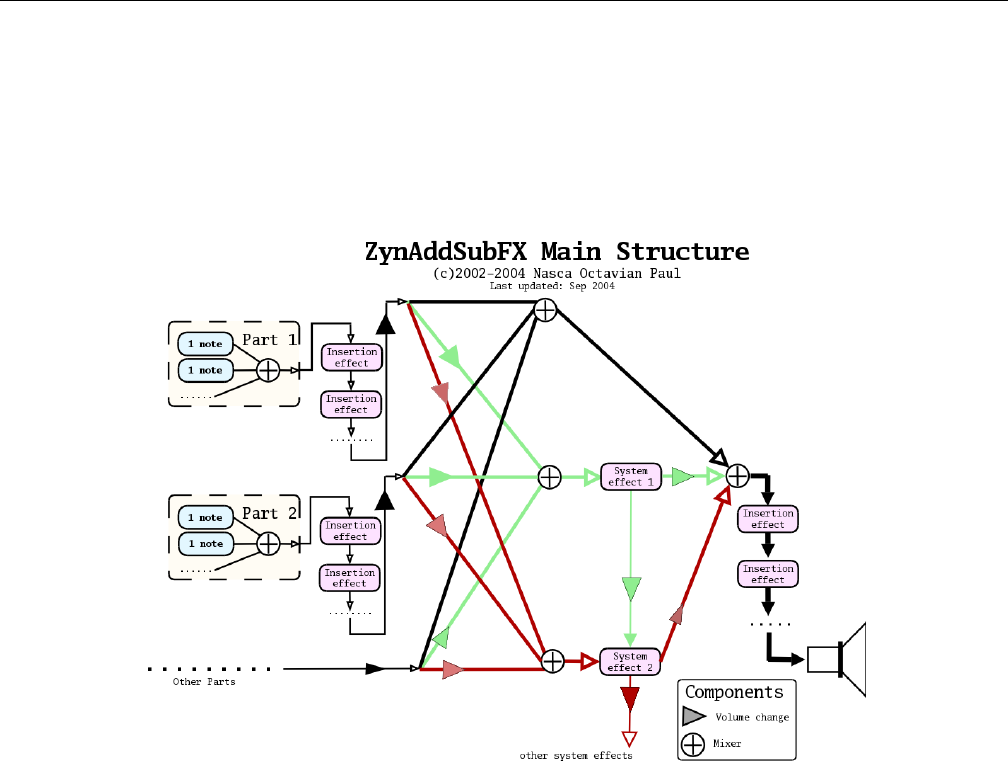
Yoshimi Software Synthesizer 21.4 Concepts / Basic Synthesis
21.4 Concepts / Basic Synthesis
This section describes some of the basic principles of synthesis, and contains suggestions on how to make
instruments that sound like they have been made with professional equipment. This applies to Yoshimi
or to any synthesizer (even if one wrote it oneself with a few lines of code). All the ideas from Yoshimi
are derived from from the principles outlined below.
Figure 165: ZynAddSubFX/Yoshimi Main Structure
For a given part, the synthesizer first creates a note. Each note’s waveform (for example, in a chord)
is summed (mixed). This complex waveform is then send to the series of Insertion effects (if any) that
are defined. Each part is then sent to a System effect and (depending on the wetness of the mix) directly
to a mixer. Additional Insertion effects (if any) are then applied. The result is the final output of the
synthesizer.
The synthesizer has three major types of parameters:
1. Master settings/parameters. Contains all parameters (including effects and instruments).
2. Instrument parameters. Contains ADDnote/SUBnote/PADnote parameters for a part.
3. Scale settings. Contains the settings of scales (Yoshimi is a micro-tonal synth) and few other
parameters related to tunings.
21.4.1 Concepts / Basic Synthesis / Panning
Pan lets one apply panning, which means that the sound source can move to the right or left. Set it to
0.0 to only hear output on the right side, or to the maximum value to only hear output on the left side.
250
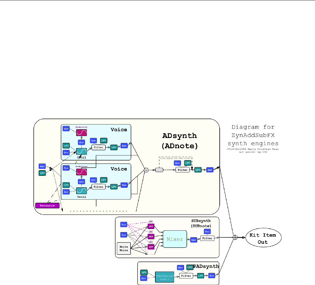
Yoshimi Software Synthesizer 21.4 Concepts / Basic Synthesis
21.4.2 Concepts / Basic Synthesis / Wetness
Wetness determines the mix of the results of the effect and its input. This mix is made the effects output.
If an effect is wet, it means that none of the input signal is bypassing the effect. If it is dry, then the effect
is bypassed completely, and has no effect.
21.4.3 Concepts / Basic Synthesis / Single Note
The idea of this synthesis model is from another synthesizer Paul Nasca wrote years ago, released on
the Internet as ”Paul’s Sound Designer”. The new model is more advanced than that project (adding
SUBsynth, more LFO’s/Envelopes, etc.), but the idea is the same.
Figure 166: ZynAddSubFX/Yoshimi Note Generation
The figure represents the synthesizer module components. The continuous lines are the signal rout-
ing, and the dotted lines are frequency controlling signals (they control the frequency of something).
The dashed lines control the bandwidths of bandpass filters. ”Env” are the envelopes, ”LFO” the Low
Frequency Oscillators, ”BPF” are band pass filters, ”bw” are the bandwidth of the BPF’s. If one uses
instrument kits, the ”note out” represents the output of the kit item.
21.4.4 Concepts / Basic Synthesis / Harmonics
Harmonics are sine waves that are multiple of the base frequency of a note. Yoshimi and ZynAddSUbFX
introduce the concept of increasing the bandwidth of a harmonic so that it is not quite a sine wave.
251

Yoshimi Software Synthesizer 21.4 Concepts / Basic Synthesis
21.4.4.1 Harmonic Bandwidth
”Harmonic bandwidth” does not refer to sample-rate, it refers to the frequency ”spread” of each harmonic.
This is the most important principle of making instruments that sound good. Unfortunately there is very
little documentation about it.
Often it is believed that the pitched sounds (like piano, organ, choir, etc.) for a single note have a
frequency, but it’s actually harmonics and nothing more. Many people try to synthesize a sound using an
exact frequency plus the harmonics, and observe that the result sounds too ”artificial”. They might try
to modify the harmonic content, add a vibrato, tremolo, but even that doesn’t sound ”warm” enough.
The reason is that the natural sounds don’t produce an exact period; their sounds are quasi-periodic.
Please note that not all quasi-periodic sounds are ”warm” or pleasant. (Nasca’s discussion of periodic
vs. quasi-periodic, and the figures he shows, are not included here.) Basically, by slightly increasing the
bandwidth of a periodic sound, it is possible to make it quasi-periodic.
A very important thing about bandwidth and natural sounds is that the bandwidth has to be increased
if one increases the frequency of the harmonic. If the fundamental frequency is 440 Hz and the bandwidth
is 10 Hz (that means that the frequencies are spread from 435 to 445 Hz), the bandwidth of the second
harmonics (880Hz) must be 20 Hz. A simple formula to compute the bandwidth of each harmonic if
one knows the bandwidth of the fundamental frequency is BW n =n∗bw1, where nis the order of the
harmonic, bw1 is the bandwidth of fundamental frequency and BWn is the bandwidth of the n’th harmonic.
If one does not increase the bandwidth according the frequency, the resulting instrument will (usually)
sound too ’artificial’ or ’ugly’. There are at least three methods of making good sounds with the above
considerations:
1. Detuning. By adding slightly detuned sounds (in Yoshimi it is called ”ADDsynth”). The idea is
not new: it has been used for thousands of years in choirs and ensembles. That’s why choirs sound
so beautiful.
2. Noise sculpting. By generating white noise, subtracting all harmonics with band-pass filters and
adding the results (in Yoshimi it is called ”SUBsynth”).
3. Generation by spectrum. By ”drawing” the above graph that represents the frequency amplitudes
on a large array, put random phases and do a single IFFT for the whole sample.
21.4.4.2 Harmonic Amplitude
An important principle of natural harmonics is to decrease the amplitude of higher harmonics on low-
velocity notes.
All natural notes have this property, because on low-velocity notes there is not enough energy to
spread to higher harmonics. On artificial synthesis one can do this by using a low-pass filter that lowers
the cutoff frequency on notes with low velocities or, if one uses FM (frequency modulation), by lowering
the modulator index. The spectrum of the sound should be almost the same according to the frequencies
and not the harmonics.
This means that, for example, the higher the pitch is, the smaller the number of harmonics it will
contain. This happens in a natural instrument because of the resonance. In this case there are many
instruments that don’t obey this, but sound quite good (example: synth organ). If one records the C-2
note from a piano and one plays it at a very high speed (8 times), the result will not sound like the C-5 key
from the piano. The pitch is C-5, but the timbre is very different. This is because the harmonic content
is preserved (the n-th harmonic will have the same amplitude in both cases) and not the spectrum (eg.
the amplitudes of the harmonics around 1000 Hz are too different from one case to another).
252

Yoshimi Software Synthesizer 21.4 Concepts / Basic Synthesis
In artificial synthesis one can use filters to add resonance or FM synthesis that varies the index
according to the frequency. In Yoshimi one can add the resonance:
1. ADDsynth: Use the Resonance, a high harmonics sound content, and filters or FM.
2. SUBsynth: Add some harmonics and use the Global Filter.
21.4.5 Concepts / Basic Synthesis / Randomness
The main reason why the digital synthesis sounds too ”cold” is because the same recorded sample is
played over and over on each key-press. There is no difference between a note played the first time and
second time. Exceptions may be the filtering and some effects, but these are not enough. In natural or
analog instruments this doesn’t happen because it is impossible to reproduce exactly the same conditions
for each note. To make a warm instrument one must make sure that it sounds slightly different each time.
In Yoshimi one can do this:
1. ADDsynth: Set the ”Randomness” function from Oscillator Editor to a value different than 0, or
change the start phase of the LFO to the leftmost value.
2. SUBsynth: All notes already have randomness because the starting sound is white noise.
3. PADSynth: The engine starts the sample from random positions on each keystroke.
In setting the randomness of the oscillator output, there are two types of randomness. The first is
group randomness, where the oscillator starts at a random position. The second is phase randomness: from
-64 (max) to -1 (min) and each harmonic (the oscillator is phase distorted) is from 1 (min) to 63 (max).
0 is no randomness. One could use this parameter for making warm sounds like analog synthesizers.
See the ADDSynth oscillator editor, Section 10.4.5 ”ADDsynth / Voice Parameters / Voice Oscillator”
on page 153, for this kind of control, named Ph.rnd or rnd.
There is now the possibility to add a ’naturalising’ random pitch element to a part. This is found in
the part-edit window. The settings are not currently saved, but will be once the control values are settled,
and there has been enough experience to decide whether it should be a part or voice setting. (In the newer
versions of Yoshimi, see the Humanise setting in the part-edit window.
21.4.6 Concepts / Basic Synthesis / Components
Important: All indexes of MIDI Channels, Parts, Effects starts from 0, so, for example, the first Part is
0. However, in other discussions of MIDI, part numbers, programs, or channels are often described as
starting from 1.
Yoshimi components:
1. Parts. They receive the note messages from MIDI Channels. One may assign a part to any channel.
A part can store only one instrument. ”Add.S” represents ADDsynth and ”Sub.S” is SUBsynth. In
recent versions of Yoshimi, the number of parts available has been increased from 16 to 64.
2. Insertion Effect. This effect applies only to one part; one can have any number of insertion effects
for one part, but the number of these cannot be bigger than NUM.INS.EFX.
3. Part Mixer. Mixes all parts. Also known as the ”Panel” or ”Mixer Panel”.
4. System Effects. Applied to all parts, one can set how much signal is routed through a system
effect.
5. Master mixer. Mixes all outputs of Parts Mixers and System Effects.
253

Yoshimi Software Synthesizer 21.4 Concepts / Basic Synthesis
21.4.7 Concepts / Basic Synthesis / Filters
Yoshimi offers several different types of filters, which can be used to shape the spectrum of a signal. The
primary parameters that affect the characteristics of the filter are the cutoff, resonance, filter stages, and
the filter type.
Cutoff: This value determines which frequency marks the changing point for the filter. In a low pass
filter, this value marks the point where higher frequencies are attenuated.
Resonance: The resonance of a filter determines how much excess energy is present at the cutoff
frequency. In Yoshimi, this is represented by the Q-factor, which is defined to be the cutoff frequency
divided by the bandwidth. In other words higher Q values result in a much more narrow resonant spike.
Stages: The number of stages in a given filter describes how sharply it is able to make changes in
the frequency response. The affect of the order of the filter is roughly synonymous with the number of
stages of the filter. For more complex patches it is important to realize that the extra sharpness in the
filter does not come for free as it requires many more calculations being performed. This phenomena is
the most visible in SUBsynth, where it is easy to need several hundred filter stages to produce a given
note.
The Q: value of a filter affects how concentrated the signal’s energy is at the cutoff frequency. For
many classical analog sounds, high Q values were used on sweeping filters. A simple high Q low pass filter
modulated by a strong envelope is usually sufficient to get a good sound.
Filter Type: There are different types of filters. The number of poles define what will happen at
a given frequency. Mathematically, the filters are functions which have poles that correspond to that
frequency. Usually, two poles mean that the function has more ”steepness”, and that one can set the
exact value of the function at the poles by defining the ”resonance value”. Filters with two poles are also
often referenced as Butterworth filters.
For the interested reader, functions having poles means that we are given a quotient of polynomi-
als. The denominator has degree 1 or 2, depending on the filter having one or two poles. In the file
DSP/AnalogFilter.cpp,AnalogFilter::computefiltercoefs() sets the coefficients (depending on the
filter type), and AnalogFilter::singlefilterout() shows the whole polynomial (in a formula where
no quotient is needed).
Filters are thoroughly described in Section 6.2 ”Filter Settings” on page 75.
21.4.8 Concepts / Basic Synthesis / Envelopes
Envelopes are long-period wave forms that are applied to frequency, amplitude, or filters. Envelopes
generate effects such as tremolo and vibrato, as well as effects that occur when a sound-generating physical
component changes shape. Envelopes are thoroughly described in Section 6.5 ”Envelope Settings” on
page 88.
21.4.9 Concepts / Basic Synthesis / Formants
Formants are basically peaks in the spectrum of the human voice cause by the various resonant features of
the human vocal tract. They can be used in Yoshimi to produce human-like sounds. Paul Nasca describes
formants:
254

Yoshimi Software Synthesizer 21.5 Concepts / MIDI
The easiest way to understand the formants/vowel is to imagine at first that each vowel contains a single
formant.
In that case, each vowel consist of a sequence of bandpass filters (with Q/frequency/amplitude). These
vowels are arranged on a line (sequence) and the space between them is controlled by the Strch (lower right).
This sequence could be used to create some simple words and the current position in that line is controlled by
the filter LFO/Envelope.
So for example, you can define two vowels like: ”vowel 1” which has the formant at 1000Hz and the ”vowel 2”
with the formant at 2000Hz and define a simple raising envelope. You should get a sliding bandpass filter between
these (eg: you get a bandpass filter which rises in the frequency from 1000Hz to 2000Hz).
If you define a second formant (you set Num formants) to 2, each vowel will get another formant. The
sound is processed using the first formant (like in the above example) and is added to the sound processed
using the second formant. The formants are bandpass-filtered in parallel as you’ve guessed.
I preferred for a vowel to have several formants (than the other way around) because I’ve arranged the
data according to the high level of abstraction (that the vowel contains several formants) instead of how it was
implemented.
It is the filter envelope that set the rate and degree to which formats are traversed. Also, the richer
the original harmonic content (e.g. a square wave), the more pronounced the effect will be.
21.5 Concepts / MIDI
It is useful to discuss some of the details of MIDI in order to understand Yoshimi. Obviously, we assume
some knowledge already, or one wouldn’t be running Yoshimi.
21.5.1 Concepts / MIDI / Learn
MIDI Learn is the ability to assign DAW, sequencer, and plugin controls to physical knobs and faders on
a MIDI control surface.
MIDI Learn is available on many software synthesizers, including Yoshimi, allowing one to control
virtually any on-screen parameter with a MIDI controller. It is a very flexible system that can adapt to a
particular MIDI device. It also allows changes made to any learned parameter to be recorded by the host
application.
21.5.2 Concepts / MIDI / Messages
Yoshimi responds to the following MIDI controller messages (34). This list seems to be more extensive
than that presented in the online ZynAddSubFX documentation.
For the controllers (numbers 75 to 78) that are not defined in GM:
•Bandwidth control (75) increases or decreases the bandwidth of instruments. The default value of
this parameter is 64.
•Modulation amplitude (76) decreases the amplitude of modulators on ADDsynth. The default
value of this parameter is 127.
•Resonance Center Frequency control (77) changes the center frequency of the resonance.
•Resonance Bandwidth control (78) changes the bandwidth of the resonance.
Some standard MIDI messages are handled a bit differently by Yoshimi:
255

Yoshimi Software Synthesizer 21.5 Concepts / MIDI
Table 34: ZynAddSubFX/Yoshimi MIDI Messages
0or 32 Bank Change (user selectable, does not force a program change)
1Modulation Wheel
2Breath Control (Yoshimi only)
6Data MSB
7Volume
10 Panning
11 Expression
38 Data LSB
64 Sustain pedal
65 Portamento
71 Filter Q (Sound Timbre)
74 Filter Cutoff (Brightness)
75 BandWidth (different from GM spec)
76 FM amplitude (different from GM spec)
77 Resonance Center Frequency (different from GM spec)
78 Resonance Bandwith (different from GM spec)
96 Data Increment
97 Data Decrement
98 NRPN LSB
99 NRPN MSB
120 All Sounds OFF
121 Reset All Controllers
123 All Notes OFF
192 Program Change (voices 1-128; see notes below)
224 Pitch Bend (see notes below)
•Program Change (192) also provides user selectable CC for voices 128-160. There is now an
option to make Program Change enable a part if it’s currently disabled.
•Key pressure (aftertouch) is internally translated as CC 130.
•Channel Pressure is internally translated as CC 129.
•Pitch Bend is internally translated as CC 128.
•Modulation The wheel only affects AddSynth and PadSynth, and then only the frequency LFO
depth. Just to make it more confusing, it changes the level from 0 up to it’s current (GUI) setting
only. Therefore, if the LFO depth is set to zero, the Mod Wheel will have no effect.
•User selectable CC for Bank Root Path change For more details of bank changes see Sec-
tion 21.3 ”Concepts / Banks and Roots” on page 249.
Instruments inside banks should always have file-names that begin with four digits, followed by a
hyphen. Otherwise the results can be rather unpredictable.
21.5.3 Concepts / MIDI / NRPN
NRPN stands for ”Non Registered Parameters Number”. NRPNs can control all System and Insertion
effect parameters. Using NRPNs, Yoshimi can now directly set some part values regardless of what channel
that part is connected to. For example, one may change the reverb time when playing to keyboard, or
change the flanger’s LFO frequency.
256

Yoshimi Software Synthesizer 21.6 Concepts / Instances
NRPNs are described in greater detail in section Section 15 ”Non-Registered Parameter Numbers”
on page 188.
21.5.3.1 Concepts / MIDI / NRPN / Vector Control
Vector control is a way to control more than one part with the controllers. Vector control is only possible
if one has 32 or 64 parts active in Yoshimi. In vector mode, parts will still play together but the vector
controls can change their volume, pan, filter cutoff in pairs, controlled by user defined CCs set up with
NRPNs.
Vector control is described in greater detail in section Section 16.3 ”Vector / Vector Control” on
page 200.
21.5.3.2 Concepts / MIDI / NRPN / Effects Control
NRPNs are very useful in modifying the parameters of the Yoshimi effects.
Effects control is described in greater detail in section Section 15.2 ”NRPN / Effects Control” on
page 190.
21.6 Concepts / Instances
Like many programs, it is possible to run multiple copies - instances - of Yoshimi. However, the risk of
doing so is that these instances cannot communicate with each other, and so can readily write to the same
files. Yoshimi regards these as external instances. It also supports internal instances, which are started
within the running main instance, and will have separate files for most settings. A description of how this
can be used follows.
Internal instances are created from the Yoshimi drop-down menu, and Yoshimi can keep track of them,
also numbering the title bars so one knows which one is being dealt with (applies to all their sub-windows,
too). Exernal instances are where Yoshimi is restarted from the desktop or some other system such as a
session manager. Although JACK/ALSA will give them independent IDs the Yoshimi instances themselves
don’t know about these IDs, which can cause a lot of confusion when saving/loading and especially when
changing configuration settings or root/bank/instrument.
So, two external instances will save default state files to the same location, and the actual saved default
will be the one last saved. Two internal ones will save to their own numberered defaults.
Previously, states were not being re-loaded. Under the new system, they are. Currently internal-instance
bank saves can still get out of step. This is an issue that will eventually be put right. This kind of synchronisation
would be impossible with external instances as they can’t directly communicate with each other.
The beauty of having per-instance independent, re-loadable default states is that they can have quite
different setups, audio destinations, learned MIDI, and patch sets. For example:
Simple user: Only has the main instance, and sets the default state to always set Ch10 as separate parts
only, for mixing with other percussion stuff. It also does a master keyshift so that Csounds as Bb, as it’s used
mostly working with brass players.
Power user: The main instance (0) gets MIDI via ALSA from an external keyboard that it specifically
looks for at startup. It has learned MIDI for the controls this keyboard can send. It also gets other channels
from Rosegarden. It sends it’s audio to JACK.
Instance 1 is all JACK and has a MIDI sequencer and arpeggiator connected. It is also configured for
separate part outputs only, for further processing.
Instance 2 is all ALSA, has its MIDI from a different keyboard, which it is set to recognise. it has its own
learned MIDI setup and and a pattern generator. Its audio is connected to a second sound card, which is then
mixed in the analog domain.
Finally, internal instances have a slightly smaller memory footprint, and marginally lighter processor load.
257

Yoshimi Software Synthesizer 21.7 Concepts / Command Line
Now that Yoshimi can be configured to auto-load last-seen instances when it starts, this all becomes
even more useful.
21.7 Concepts / Command Line
This section covers a few terms useful in discussing the command line.
21.7.1 Concepts / Command Line / level
The term level is used in the description of the new command-line facility of Yoshimi. A level is simply
a related group of parameters or a location where one can go to for making changes. Important levels are:
the top level; system effects; part; and more.
21.8 Concepts / LV2 Plugin
Yoshimi now runs as an LV2 plugin. TODO: Describe LV2 at a high-level.
21.9 Concepts / Numbering
When implementing CLI access, the decision was made to use the internal counting system which, like
almost everything else in computer programming, starts at zero. This caused a few anomalies, as most of
the GUI numbering is from one. This discordance was becoming much more of a problem, most obviously
with the Vector Control and MIDI learn windows. Now all the messages use the GUI number bases. This
makes MIDI learn look more sensible; when sending reports to the console window there is no difference
in numbering re the user-interface.
CLI entries have also been converted. All standard CLI inputs, as well as the return message numbers,
should start from 1 with the following exceptions:
•Bank roots
•Banks
•CCs
These items follow standard MIDI practice (and do the same in the GUI). One of our most prolific
CLI users who, while preferring all zero as a base, appreciates the difficulties and can manage as long as
things are consistent.
Banks and bank roots continue to start from zero - this is what everyone expects from these as MIDI
commands. Indeed, all MIDI CC numbers will do so. However, channel numbers, program change, part
numbers, engines, etc. start from one. Effects are an outlier. They seem to already start from one but
that’s because zero is the value for ’no effect’.
22 Building Yoshimi
This section describes building and debugging Yoshimi. Building Yoshimi requires getting the source code,
making sure all of the necessary dependencies are installed, and using CMake to set up the build.
258

Yoshimi Software Synthesizer 22.1 Yoshimi Source Code
The source-code is located at its main location ([19]) or its alternate location ([20]).
Like ZynAddSubFX,Yoshimi uses CMake as its build system [25]. CMake is a preprocessor that can
generate project build setups for Visual Studio, UNIX make, and Xcode.
22.1 Yoshimi Source Code
Get the source code version you want from SourceForge (http://sourceforge.net/projects/yoshimi/
files/1.3/). Download the desired tar-ball and unpack it in your work area.
Since SourceForge has had some issues, the Yoshimi team has wisely hosted the source code at another
site as well, https://github.com/abrolag/yoshimi. One can grab the whole git repository there using
the following command in your work area:
$ git clone https://github.com/abrolag/yoshimi.git
Please note that this code base comes with two files, INSTALL and INSTALL CUSTOM which elaborate
on build options well beyond what is discussed here.
22.2 Yoshimi Dependencies
As of recent versions of Yoshimi 1.3.9, building Yoshimi requires C++11. For GNU builds, this requires
gcc 4.7 and above.
To save some wasted time, make sure the development versions of the following packages have been
installed using your Linux distribution’s package manager:
•pkg-config
•libz
•fftw3f
•mxml
•ALSA (libasound)
•JACK
•Boost
•fontconfig
•libcairo
•FLTK
•lv2
These package names are from Debian Jessie:
•automake
•build-essential
•cmake-curses-gui
•dssi-dev
•fluid
•libboost-dev
•libcairo2-dev
•libfftw3-dev
259

Yoshimi Software Synthesizer 22.3 Build It
•libfltk1.3-dev
•libglu1-mesa-dev
•libjack-jackd2-dev
•libjpeg-dev
•libmxml-dev
•libncurses5-dev (new dependency)
•libreadline-dev (new dependency)
•libxft-dev
•libxinerama-dev
•libxml2-dev
•xutils-dev
•zlib1g.dev
LV2 plugin adds one more dependency:
lv2-dev with minimum version ¿= 1.0.0.
Other distros may have slightly different names or version numbers, and may even have these installed
by default. If in doubt, try looking for just the main part of the name, but with the -dev extension where
appropriate.
22.3 Build It
The following instructions are for an in-source build. An in-source build is simpler if you just want to
build and install Yoshimi.
We will also show how to set up for an out-source-build, which keeps the build products out of the
way.
The location of CMakeList.txt does not appear to be standard, so these instructions differ in details
from the build instructions of ZynAddSubFX. Basically, the build is based in the project’s src directory,
instead of its root directory.
1. Enter the source directory where the code was unpacked.
2. Generate the project build-files:
$ cd src
$ cmake ..
$ cmake .
3. Build the code and install it (as root):
$ make
# make install
Here is how to make an out-of-source debug. Despite what cmake documentation (and Googling)
says, using a command like the following does not work unless you have ccmake installed.
$ cmake -DCMAKE_BUILD_TYPE=Debug ..
$ ccmake
260

Yoshimi Software Synthesizer 22.3 Build It
In Debian Linux, install the cmake-curses-gui package to get access to ccmake. Or use the shorter
cmake -DBuildForDebug=on .. command below.
1. Enter the source directory where the code was unpacked.
2. Create a ”Debug” or ”Release” directory for an out-of-source build:
$ cd src
$ mkdir Debug
3. Generate the project build-files in the Debug directory.
$ cd Debug
$ cmake -DBuildForDebug=on ..
$ make
The output file, and executable name yoshimi is now ready to run (and be debugged).
Here is a debugging use case we used in Yoshimi 1.3.5.1 and slightly earlier versions. Here is how to
verify the bug:
1. Run the following command:
$ yoshimi -a -A
2. Navigate the following command path: Menu / Instrument / Show Banks
3. Select the RENAME button.
4. Select the bank (e.g. Arpeggios).
5. In the file prompt that comes up, click Cancel.
6. Observe a ”Segmentation fault”.
To avoid a lot of debugging, let valgrind find the bug for you. Install valgrind. Then, in the src/Debug
directory, run:
$ valgrind --log-file=yoshvalgrind.log ./yoshimi -a -A
In the log file, one sees that the last good call was in the Bank :: readOnlyBank() function. That
would be a good place to put a breakpoint.
However, even without valgrind, this particular bug is easy to find under the debugger. The steps are
simple:
$ cd src/Debug
$ gdb ./yoshimi
(gdb) r -a -A
Then repeat the steps above that trigger the bug. One sees
Program received signal SIGSEGV, Segmentation fault.
Issue the command ”backtrace” at the (gdb) prompt. There will be a list of stack frames starting at
0. Frame 1 is in Yoshimi, so issue the command ”frame 1”, a see
261

Yoshimi Software Synthesizer 22.4 Yoshimi Code Policies
if (strlen(tmp) > 2) ...
tmp is a null pointer here; we need to add an initial check for the null pointer there to avoid triggering
the crash.
Not worry now, though, the bug has been officially fixed.
22.4 Yoshimi Code Policies
Yes, we actually have Yoshimi code policies. Look how many there are! :)
If the version string contains a 4th number this will always be just a bugfix, and will never have
features added or changed from the main version. For example:
•yoshimi-1.3.5 Main version.
•yoshimi-1.3.5.1 First bugfix.
•yoshimi-1.3.5.2 Second bugfix. (Surely not!)
We won’t accept fixes for spelling errors in the code. For a start, from bitter experience it is fatally
easy to change two variables to the same name! Also, there’s no point, after all they are only a mnemonic
for memory addresses etc. ’volume’ and ’LFO’ could just as well be ’turnyfing’ and ’derfingwotwiggles’.
To avoid possible confusion, from now on ’master’ will display the last released version number
(without bugfix digits) with an ’M’ suffix - unless it is a release candidate in which case the suffix will be
rc[n]. For example:
•Last release was yoshimi-1.3.5.2
•Master is shown as yoshimi-1.3.5 M
XML files created with this release will have: major version 3 and minor version 5.
If using Fluid to edit GUI files, please close all windows and collapse all menus before the last save.
I know it’s tedious, but it avoids storms of spurious ’changes’ that make genuine ones harder to see.
23 Summary
In summary, we can say that you will absolutely love Yoshimi.
A car analogy: A sample player is a drive along a straight, wide, almost new highway with only 2 other cars
in sight, on a lightly overcast summer’s day in a Ford Fiesta at around 40 MPH. Yoshimi is a white-knuckle
trip over a Swiss mountain pass in a blizzard, at night, facing donkeys, trucks and bandits, while driving an
open-frame kit car doing 90 + In recent times we’ve been able to dispose of the donkeys, and the bandits are
on the run :)
262

Yoshimi Software Synthesizer
24 References
This section provides references for this Yoshimi user’s manual, as well as some other information.
Although the Yoshimi project is based on SourceForge, it also has a mirror on GitHub, and a
mailing list on FreeLists.Org. One can subscribe with an e-mail to: yoshimi-request@freelists.org or by
visiting: http://www.freelists.org/list/yoshimi. To post to the list, email to: yoshimi@freelists.org
The archive of the old SourceForge mailing list is found at: https://www.freelists.org/archive/
yoshimi.
References
[1] Alf (naihe2010@126.com). apvlv is a PDF/DJVU/UMD/TXT Viewer Under Linux/WIN32 and its
behaviour is like Vim. https://naihe2010.github.io/apvlv/. 2010.
[2] Will J. Godfrey. A discussion of making Bank/Root specifications more regular. http://
sourceforge.net/p/yoshimi/mailman/message/33200765/. 2014.
[3] Chris Ahlstrom. Yoshimi Advanced User Manual. https://github.com/ahlstromcj/
yoshimi-doc/. This user’s manual is still an ever more complete work-in-progress. 2017.
[4] Chris Ahlstrom A Yoshimi Cookbook. https://github.com/ahlstromcj/yoshimi-cookbook/.
2015.
[5] Robert Bristow-Johnson. Cookbook formula for audio EQ biquad filter coefficients. http://www.
musicdsp.org/files/Audio-EQ-Cookbook.txt. 2005. The ”files” directory has a number interesting
files as well.
[6] Cormi. Cormi Collection. https://www.freesound.org/people/cormi/. His
cormi57.wordpress.com site has a lot of other nice sound material, as well. 2015.
[7] Straulino. A collection of instruments. http://www.straulino.ch/zynaddsubfx/,http:
//www.straulino.ch/zynaddsubfx/Drums_DS_v2012-12-08.zip,http://www.straulino.
ch/zynaddsubfx/ZynAddSubFX_Natural_Drum_Kit_Demo_v2012-06-22.ogg.
[8] Folderol (Will). A collection of instruments. http://www.kara-moon.com/forum/index.php?
topic=762.0.
[9] Will Godfrey. Will Godfrey’s Music. http://www.musically.me.uk. See the ”Bits ’n Stuff” link
especially.
[10] Will J. Godfrey. A discussion of licensing issues with Youshimi and ZynAddSubFX components, and
FLTK library versions. http://sourceforge.net/p/yoshimi/mailman/yoshimi-devel/. 2015.
[11] caonoize. ZynAddSubFX by paulnasca: Downloads, Banks, Patches, etc. http://www.kvraudio.com/
product/zynaddsubfx_by_paulnasca/downloads. 2015.
[12] mmxgn. Instruments made with zynaddsubfx/yoshimi. https://github.com/mmxgn/
instruments-zyn. 2011.
[13] Rakarrack team. The download site for the Rakarrack software effects engine. http://rakarrack.
sourceforge.net/. 2015.
263

Yoshimi Software Synthesizer REFERENCES
[14] LinuxMusicians newsgroup. Ring Modulation in ZynAddSubFX. http://linuxmusicians.com/
viewtopic.php?f=1&t=8178. 2012.
[15] Manuel Op de Coul (coul@huygens-fokker.org). The Scala Musical Tuning Application. http://www.
huygens-fokker.org/scala/. Scala is a powerful software tool for experimentation with musical
tunings, such as just intonation scales, equal and historical temperaments, microtonal and macrotonal
scales, and non-Western scales. 2014.
[16] Sharphall. How to create drum sounds in ZynAddSubFX or Yoshimi, Part 1. http://sharphall.
org/docs/zynaddsubfx_yoshimi_drum_tutorial.php. Never got continued, unfortunately.
[17] Gordon Reid. Synth Secrets: Creative Synthesis. http://www.soundonsound.com/sos/
allsynthsecrets.htm. 1999-2004.
[18] Graham. A small musical website. http://x31eq.com and specifically http://x31eq.com/zasf.
[19] Yoshimi team (abrolag@users.sourceforge.net). The download site for the Yoshimi software synthe-
sizer. http://yoshimi.sourceforge.net/. 2015.
[20] Yoshimi team. The alternate location for the Yoshimi source-code. https://github.com/abrolag/
yoshimi now. 2015.
[21] Yoshimi team. Yoshimi user/developer mailing list. http://www.freelists.org/list/yoshimi.
2015.
[22] Yoshimi team. Yoshimi user/developer mailing list archive. http://www.freelists.org/archive/
yoshimi. 2015.
[23] Mark McCurry, Paul Nasca (ZynAddSubFX team). The download site for the ZynAddSubFX software
synthesizer. http://zynaddsubfx.sourceforge.net/. 2015.
[24] Paul Nasca? The download site for the ZynAddSubFX banks, instruments, parameters, and demos.
http://zynaddsubfx.sourceforge.net/doc/instruments/. 2009.
[25] ZynAddSubFX team. Building ZynAddSubFX. http://zynaddsubfx.sourceforge.net/Doc/#_
appendix_b_building_zynaddsubfx. 2009.
[26] AMSynth team. Provides a number of OGG demos of ZynAddSubFX sounds. It also includes the
author’s own ”Vanilla” bank, and links to additional patch collections and demonstration videos.
http://www.amsynth.com/zynaddsubfx.html.
[27] Mark McCurry, Paul Nasca. ZynAddSubFX online manual. http://zynaddsubfx.sourceforge.
net/Doc. 2015.
[28] Paul Nasca. Original ZynAddSubFX manual, ODT format. http://linux.autostatic.com/docs/
zynaddsubfx_manual-v0.1.odt. 2011.
[29] Paul Nasca. Original ZynAddSubFX manual, PDF format. http://linux.autostatic.com/docs/
zynaddsubfx_manual-v0.1.pdf. 2011.
[30] Paul Nasca, Mark Murray. The download package for the ZynAddSubFX source-code. http:
//downloads.sourceforge.net/project/zynaddsubfx/zynaddsubfx/2.5.0/zynaddsubfx-2.5.
0.tar.gz.
264


Index
–alsa-audio[=device], 245
–alsa-midi[=device], 245
–auto-connect, 246
–autostart-jack, 246
–buffersize=size, 245
–define-root, 245
–help, 246
–jack-audio[=server], 246
–jack-midi[=device], 245
–jack-session-file[=file], 246
–jack-session-uuid[=uuid], 246
–load-instrument=file, 246
–load=file, 246
–name-tag=tag, 246
–no-gui, 245
–oscilsize=size, 246
–samplerate=rate, 246
–show-console, 245
–state[=file], 246
–usage, 246
–version, 246
-?, 246
-A, 245
-D, 245
-J, 246
-K, 246
-L, 246
-N, 246
-R, 246
-S, 246
-U, 246
-V, 246
-a, 245
-b, 245
-c, 245
-i, 245
-j, 245
-k, 246
-l, 246
-o, 246
-u, 246
..—hyperpage, 239
.banks, 23,27
.config, 23,24
.history, 23,26
.instance(n), 23,26
.kbm, 234
.scl, 234
.state, 23,25
.windows, 23,28
.xiy, 23
Yoshimi format, 23
.xiz, 23,26
Legacy format, 23
.xly, 23,29
.xmz, 23,24
.xpz, 23,26
.xsz, 23,26
.xvy, 23
/, 239
? or help, 242
˜/.yoshimi history, 23
0/+, 80
16/32/64 Parts, 74
440Hz, 152,180
A Freq, 68
A MIDI, 68
A Note, 68
A.dt, 90,94,95,180
A.M, 117
A.R, 86,87
A.S, 117
A.val, 94,180
A.value, 95
accessibility, 16
add bank [s], 239
Add point, 92
Add preset directory..., 63
add root [s], 240
Add root directory..., 61
Add to Favorites, 54
ADDsynth, 143
addsynth
coarse detune, 148
detune type, 148
detune value, 147
filter env, 147
filter lfo, 147
filter params, 147
266

Yoshimi Software Synthesizer INDEX
freq slider, 148
frequency env, 148
frequency lfo, 148
group, 146
H.rnd, 160
H.rnd knob, 160
mag type, 160
octave, 148
oscillator graph, 160
pan, 146
punch strength, 146
punch stretch, 146
punch time, 146
punch vel sens, 147
random pan, 146
relative bw, 148
rnd, 160
Stereo, 146
vel sens, 145
voice parameters, 148
volume, 145
waveform graph, 160
AddSynth Oscillator Size, 35
Adpt.Harm, 175
Adpt.Harm. baseF, 176
Adpt.Harm. pow, 176
Adpt.Harm. Slider, 176
ADsynth, 184
alienwah
delay, 119
depth, 119
dry/wet, 118
feedback, 119
l/r, 119
lfo frequency, 118
lfo randomness, 118
lfo shape, 119
phase, 118
phase diff, 119
preset, 118
subtract, 119
volume, 118
ALSA
audio device, 43
MIDI Source, 43
sample rate, 43
Set as preferred audio, 43
Set as preferred MIDI, 43
Alsa Audio Device, 43
Alsa Midi Source, 43
amp, 97
AMPLITUDE, 177
Amplitude Env, 179
Amplitude Env, Stock + Enable, 151
Amplitude LFO, Stock + Enable, 151
AmpMode, 165
AmpMultiplier, 165
Analog, 129
anti-auto-clutter, 51
Apply, 171
asterisk, 35
at-sign, 240
attack, 88
Author and Copyright, 143
Autoconnect audio, 41
automation
16/32/64 parts, 74
controls, 74
NRPNs, 74
part audio, 75
part control, 74
vector control, 74
A—hyperpage, 68
B, 126
B.F.Mod, 172
B.Width Scale, 179
BandWidth, 167,179
Bandwidth, 107,140
bandwidth
attack time, 180
attack value, 180
enable, 180
forced release, 180
release time, 180
release value, 180
stretch, 180
Bandwidth Env, 179
Bandwidth Scale, 167
Bank Change, 45
Bank Matrix, 58
Bank Names, 49
Bank Root Change, 45
Banks, 51
banks, 27
current bank, 58
267

Yoshimi Software Synthesizer INDEX
EXPORT, 58
IMPORT, 58
instrument, 58
matrix, 58
base, 166
Base Channel, 196
Base F, 171
Base Func. Spectrum Graph, 171
Base Func. Waveform Graph, 171
BaseType, 164
Block, 208
bottom panel
instrument edit, 135
instrument enable, 136
instrument name, 135
key limit, 137
key shift, 137
M, 137
m, 136
maximum note, 136
MIDI channel, 136
minimum note, 136
mode, 136
pan, 136
part maximum, 134
part number, 134
portamento enable, 136
R, 137
sound meter, 137
system effect sends, 137
velocity offset, 136
velocity sensing, 136
volume, 136
Breath, 139
breath control, 14
brightness, 140
bugs
compressed XML preview, 55
in document, 18
BW, 132
BWdepth, 140
BwDepth, 138
bypass, 133
Bypass Global F, 151
C, 83,86–88,90,109,133,157,176,178
C.f, 97
C.f. (knob), 81
C.freq, 79
Category, 78
CC, 207
CC monitor, 46
cent, 247
Center, 68
center, 68
center frequency, 79
cents, 167
CFdepth, 140
Chan, 207
Change ID, 61
Channel, 103
channel switcher, 103
chorus
delay, 121
feedback, 121
l/r phase, 121
l/r routing, 121
lfo depth, 121
lfo freq, 121
lfo randomness, 121
lfo type, 121
substract, 121
Clear, 82,176,208
CLI, 209
cli
command level, 213
context level, 213
clipboard
copy, 99
copy type, 99
list, 99,100
paste, 99,100
paste type, 100
Clipboard list, 99,100
Close, 52,83,93,104,106,133,139,143,176,178
close scales, 70
Close Unsaved, 34
Close Window, 157,185
Close, Scales Dialog, 70
Clr, 172
cmd, 209
.., 239
/, 239
add bank, 239
add root, 240
at-sign, 212,240
268

Yoshimi Software Synthesizer INDEX
direct access, 242
exit, 242
export bank, 239
help, 242
import bank, 239
list banks, 240
list effects, 240
list history, 240
list instruents, 240
list operator, 240
list parts, 240
list roots, 240
list setup, 240
list vector, 240
load instrument, 240
load vector, 240
remove bank, 239
remove root, 240
reset, 242
save instrument, 240
save patchset, 240
save setup, 240
save vector, 240
set activate, 240
set alsa audio, 240
set alsa midi, 240
set available, 241
set bank, 241
set ccbank, 241
set ccroot, 241
set extend, 241
set insert effects, 241
set jack midi, 241
set jack server, 241
set part channel, 241
set part destination, 241
set part program, 241
set preferred audio, 241
set preferred midi, 241
set program, 241
set reports, 241
set root, 241
set shift, 241
set system effects, 241
set vector, 242
set vector cc, 241
set vector control, 242
set vector features, 242
set vector program, 242
set volume, 242
stop, 242
to top level, 239
up one level, 239
Coarse Det, 181
Coarse det, 148,152
command level, 202,210
command line, 209
Comment, 68
comment, 68
Comments, 143
config, 24
.bankdir, 28
.banks, 23,27
.config, 23
.history, 23,26
.instance(n), 23,26
.kbm, 234
.scl, 234
.state, 23,25
.windows, 23,28
.xiy, 23
.xiz, 23,26
.xly, 23,29
.xmz, 23,24
.xpz, 23,26
.xsz, 23,26
.xvz, 23
control
reset, 21
Control Function, 208
control point, 91
Controller, 106,197
controllers
bandwidth, 107,140
bandwidth depth, 138
breath, 139
close, 139
exp bandwidth controller, 138
expression, 107,139,140
expression mod wheel, 138
filter cutoff, 140
filter cutoff depth, 139
filter frequency, 107
filter Q, 140
filter q, 107
filter Q depth, 139
269

Yoshimi Software Synthesizer INDEX
fm amplitude, 139
fm gain, 107
mod wheel depth, 138
modulation, 140
modulation wheel, 107
panning, 107
panning depth, 138
pitch wheel range, 139
portamento, 107
portamento depth, 141
portamento proportional, 140,141
portamento rate, 141
portamento receive, 140
portamento threshold, 140
portamento threshold type, 141
portamento time, 140
portamento time, down/up, 140
reset all, 139
resonance bandwidth, 107
resonance BW depth, 140
resonance center frequency, 107
resonance CF depth, 140
sustain, 107
sustain pedal enable, 139
volume, 107
volume enable, 139
volume range, 139
copy, 90
Copy to Clipboard, 99
Copy to Preset, 99
Create Directory, 55
current
root, 61
current bank, 58
cutoff frequency, 79
Cval, 106
D.dt, 90,95
D.val, 95
D/W, 116,118,129,132
Damp, 125,133
dB, 82
decay, 88
Default, 143
default
asterisk, 35
Delay, 84,86,87,119,121,125,150
DELETE, 52
Delete point, 93
Depth, 84,86,87,129
Detune, 101,147,152,158,180
Detune Type, 148,152,181
Detune Value, 158
Direct Access, 242
direct access
kit, 185
Direct part audio, 75
Directory Bar, 55
dist, 129
distortion
drive, 123
hpf, 123
level, 123
lpf, 123
negate, 123
stereo, 123
type, 123
distortion effect
panning, 122
Dpth, 119,121
Drive, 123
Drum mode, 185
dynfilter
a.inv, 117
a.m., 117
a.s., 117
dry/wet, 116
filter, 116
lfo depth, 117
lfo freq, 116
lfo randomness, 116
lfo stdf, 117
lfo type, 117
pan, 116
preset, 116
volume, 116
E, 90,92
E/R, 132
echo
crossover, 125
damp, 125
delay, 125
feedback, 125
l/r delay, 125
Edit, 103,135,158
270

Yoshimi Software Synthesizer INDEX
keys, 135
edit, 90
addsynth, 143
author/copyright, 143
category, 142
close, 143
comments, 143
default, 143
effects, 143
humanise, 143
kit, 143
padsynth, 143
rnd det, 143
subsynth, 143
Effect Name, 109
Effect Number, 109
Effects, 143
effects
bypass, 113,143
copy dialog, 109
insertion tab, 111
name, 109
number, 109
panel, 110
paste dialog, 110
reports, 111
send to, 109
system tab, 109
to, 112
Effects Panel, 110
EffType, 133
Enable, 81,87,94,151,153,184
Enable Auto Instance, 40
Enable Bank Root Change, 45
Enable CLI, 40
Enable Extended Program Change, 46
Enable GUI, 40
Enable Incoming NRPNs, 46
Enable Microtonal, 68
Enable part, 103
Enable Part On Program Change, 45
Enable Program Change, 45
Enabled, 136,180,182
envelope
add point, 92
attack, 88
attack time, 90,94,95
attack value, 94,95
close dialog, 93
decay, 88
decay time, 90,95
decay value, 95
delete point, 93
editor, 92
enable, 94
forced release, 90,93–95
freemode, 92
freemode enable, 91
linear, 90,93
linearity, 95
release, 88
release time, 90,94,95
release value, 94
stretch, 90,93–95
sustain, 88,93
sustain value, 90
eq
band, 126
filter freq, 126
filter gain, 126
filter q, 126
filter type, 126
gain, 126
graph, 126
stages, 126
Eq.T, 152,180
exit, 242
Exp BW, 138
Exp MWh, 138
EXPORT, 58
Export, 178
export bank [s [n1]] [n2] [s], 239
Expr, 139
Expression, 107,140,204
extended program, 49,249
Extended Program Change, 46
F.R, 86,88
Favorites, 54
Fb, 119,121,125,129
Feature 1, 197
Feature 2, 198
Feature 3, 198
Feature 4, 198
file
banks, 27
271

Yoshimi Software Synthesizer INDEX
config, 24
history, 26
instance, 26
instrument, 26
patch set, 24
preset, 26
scale, 26
state, 25
windows, 28
File Systems, 54
Filename, 55
FILTER, 177
Filter, 116,174
filter
0/+, 80
analog, 78
category, 78
cutoff, 76
formant, 78
frequency tracking amount, 79
gain, 79
order, 77
Q, 76
resonance, 76
stages, 77,79
state variable, 79
StVarF, 79
tracking, 80
type, 75,79
velocity sensing function, 79
Filter Cutoff, 140,204
Filter Env, 147,182
Filter Env, Stock + Enable, 151
Filter Freq, 107
Filter LFO, 147
Filter LFO, Stock + Enable, 151
Filter p, 174
Filter Params, 147,182
Filter Params, Stock, 151
Filter Q, 107,140,204
Filter Stages, 182
Filter Type, 79
Filter Wheel 1, 174
Filter Wheel 2, 174
First Note, 70
FltCut, 139
FltQ, 139
FM, 155
FM Gain, 107
FMamp, 139
ForceH, 168,181
Formant, 97
Formants, 97
formants
amplitude, 97
amplitude control, 96
center frequency, 96
cf, 97
frequency, 97
graph, 96
mouse control, 96
number, 97
number of, 97
octaves, 97
Q, 97
Q control, 96
range control, 96
reversed, 98
seq position, 98
seq size, 97
seq stretch, 98
slowness, 97
vowel clearness, 97
vowel number, 97
vowel position, 98
Formants Graph Window, 96
Fr.Sl, 97
frame, 247
frcR, 90,93–95,180
FreeMode, 91,92
Freq, 86,87,116,118,121,126,129
freq, 97
freq.tr, 79
FreqMlt, 164
FREQUENCY, 177
Frequency, 84
Frequency Env, 148,181
Frequency Env, Stock + Enable, 152
Frequency LFO, 148
Frequency LFO, Stock + Enable, 152
frequency modulator, 155
FREQUENCY Slider, 180
FREQUENCY slider, 148,152
frequency tracking amount, 79
Full/Upper/Lower, 164
FX No, 133
272

Yoshimi Software Synthesizer INDEX
FX.r, 184
Gain, 126
gain, 79
Gain (Filter), 126
Graph, 126
Graph Window, 81
H.rnd, 160
H.rnd knob, 160
Harmonic Content Window, 166
Harmonic Shift, 175
Harmonic Shift preH, 175
Harmonic Shift R, 175
Harmonics Amplitude, 175
Harmonics Bandwidth, 175
Harmonics Plot, 168
Harmonics Scrollbar, 175
Hide Non Fatal Errors, 39
Hide Voice List, 159
history, 26
HPF, 123,133
humanise, 143
Humanise (Rnd. Det.), 143
hyper, 129
I.del, 132
I.delfb, 132
Ignore Reset all CCs, 46
IMPORT, 58
Import .kbm file, 70
Import .SCL file, 68
import bank [s [n1]] [n2] [s], 239
Include disabled data in XML files, 40
insertion effect
-1, 112
-2, 112
disable, 112
master out, 112
Insertion Effects Tab, 111
instance, 26
Instrument, 58
instrument, 26,247
Instrument and Bank Matrix, 51
Instrument List, 55
Instrument Name, 135,184
instruments
bank matrix, 51
bank names, 49
banks, 51
Close, 52
DELETE, 52
RENAME, 51
roots, 51
SAVE, 52
SELECT, 51
show engines, 52
SWAP, 52
Internal Buffer Size, 36
InterpPk, 81
Inv., 117
Invert Keys, 68
JACK
autoconnect audio, 41
MIDI source, 41
server name, 41
set as preferred audio, 41
set as preferred MIDI, 41
Jack Midi Source, 41
Jack Server, 41
kbm file, 70
Key Limit, 137
Key Oct, 105
Key Shift, 101,137
key shift, 68
keyboard, 68
Keyboard Mapping, 68
keys, 68
KHz, 82
kit
addsynth, 184
close, 185
direct access, 185
drum mode, 185
enable, 184
fx.r, 184
M, 184
m, 184
maximum key, 184
minimum key, 184
mode, 184
mode crossfade, 184,185
mode multi, 184,185
mode off, 184
mode single, 184,185
273

Yoshimi Software Synthesizer INDEX
Mute, 184
name, 184
padsynth, 184
R, 184
row number, 184
subsynth, 184
Kit Edit, 143
knobs, 73
coarse control, 73
fine control, 73
fine control, scroll, 73
home position, 73
left-drag, 73
right-click, 73
right-drag, 73
scroll-wheel, 73
super-fine, scroll, 73
L, 90,93,95
L/R, 119,121,129
Last Note, 70
legato, 14
Level, 123
LFO, 129
amount, 86
amplitude randomness, 86
continuous mode, 85,86
delay, 84,86
depth, 84,86
frequency, 84,86
frequency randomness, 86
function, 84
function type, 86
randomness, 85
shape, 84
start phase, 84
starting phase, 86
stretch, 85,86
type, 84,86
lfo
continuous, 87
copy, 88
delay, 87
depth, 87
enable, 87
frequency, 87
paste, 88
random amplitude, 87
random frequency, 88
start phase, 87
stretch, 87
type, 88
LFO Type, 117
LFO type, 119,121
LfoD, 117
Limit, 207
list banks [n], 240
list effects [n], 240
list history [s], 240
list instruments [n], 240
list parts, 240
list roots, 240
list setup, 240
list vector [n], 240
Load, 208
Load External
create new directory, 55
directory bar, 55
favorites, 54
filename, 55
instrument list, 55
ok/cancel, 55
preview checkbox, 55
preview pane, 55
show, 53
show hidden files, 55
load instrument [s], 240
load patchset [s], 240
load vector [s], 240
Local Oscillator, 156
Log Incoming CCs, 46
Log Load times, 40
Log XML headers, 40
LPF, 123,132
LRc, 125
LRdl, 125
LV2
scales, 65
M, 137,184
m, 136,184
Mag. Type, 182
Mag.Type, 160,170
Main, 103
Main Settings
buffer size, 36
274

Yoshimi Software Synthesizer INDEX
Hide Non-Fatal Errors, 39
Include disabled data, 40
instrument file format, 38
Log XML headers, 40
oscillator size, 35
PADsynth Interpolation, 36
Send Reports Destination, 37
Show Splash Screen, 40
Virtual Keyboard Layout, 36
XML compression level, 37
Make current, 61
Make default presets, 63
Manage Favorites, 54
Map, 70
Map Size, 70
mapping, 68
Maps Oct, 105
Master Bandwidth, 140,204
master reset, 101
master reset, ctrl, 101
Max dB (wheel), 81
Max key, 184
Maximum Note, 136
Middle Note, 70
Midi, 136
midi
learn, 203
learn, slider quirk, 205
MIDI CC
breath control, 14
legato, 14
Midi Channel, 105
MIDI controls, 204
MIDI Learn, 203
.xly, 23
200 lines, 206
Block, 208
CC, 207
Chan, 207
Clear, 208
Control Function, 208
Limit, 207
Load, 208
Min/Max, 207
Mute, 207
Recent, 208
Save, 208
MIDI settings
bank change, 45
bank root change, 45
enabable incoming NRPN, 46
enable bank root change, 45
enable extended program change, 46
enable part change, 45
enable program change, 45
extended change, 46
Ignore Reset all CCs, 46
Log Incoming CCs, 46
Show Learn Editor, 46
Min key, 184
Min/Max, 207
Minimum Note, 136
Minus, 150
Mixer Panel, 101
Mod, 174
Mod AMPLITUDE, 156
Mod FREQUENCY, 156
Mod. Wheel, 107
Mod. Wheel 1, 174
Mod. Wheel 2, 174
Mod. Wheel 3, 174
Mode, 136,184
Modulation, 140,204
modulation oscillator, 144
modulator
amplitude, 156
external, 155
frequency, 155,156
morph, 155
oscillator, 156
phase, 155
PWM, 155
ring, 155
source, 156
type, 155
Modulator Source, 155
ModWh, 138
MORPH, 155
morph modulator, 155
mouse
right-click, 72,73
Mute, 184,207
Name, 68
Neg, 123
Neg Input, 98
275

Yoshimi Software Synthesizer INDEX
new
in document, 18
MIDI Learn, 32
right-click, 72
vectors, 32
View Manual, 32
No, 184
No. (1 to 8), 158
no.oct, 166
Notes per Octave, 68
NRPNs, 74
nts./oct, 68
Oct, 81,97
Octave, 105,148,152,181
of, 134
OK/Cancel, 55
ON, 70
On, 150
Open current, 61
Options, 197
oscillator
external, 155
local, 155
Oscillator Spectrum Graph, 160,170
Oscillator Waveform Graph, 160,170
Overtones Position, 181
OvertonesPosition, 168
P, 83,88,90,110,133,157,176,178,246
P.Stc, 146
P.Str, 146
P.t, 146
P.Vel, 147
PADsynth, 143,184
padsynth
amp mode, 165
amp mult, 165
amplitude section, 177
apply button, 171
bandwidth, 167
bandwidth reading, 167
bandwidth scale, 167
base function, 171
base function spectrum, 171
base function waveform, 171
bf mod, 172
close, 178
copy, 178
export, 178
forceh, 168
freq mult, 164
harm editor clr, 172
harm editor filter, 174
harm editor filter p, 174
harm editor filter wheel, 174
harm editor mod, 174
harm editor mod wheel, 174
harm editor spadj, 174
harm editor spadj wheel, 175
harm editor use-as-base, 172
harm editor wsh, 172
harm editor wsh value, 172
harm editor wsh wheel, 174
harmonic base, 166
harmonic content, 166
harmonic fup, 164
harmonic no. of octaves, 166
harmonic par1, 165
harmonic par2, 165
harmonic profile, 166
harmonic sample size, 166
harmonic samples per oct, 166
harmonic sfreq, 164
harmonic size, 164
harmonic stretch, 164
harmonic type, 164
harmonic width, 164
harmonics, 175
harmonics amplitude, 175
harmonics bandwidth, 175
harmonics basef, 176
harmonics clear, 176
harmonics close, 176
harmonics copy, 176
harmonics paste, 176
harmonics plot, 168
harmonics pow, 176
harmonics scrollbar, 175
harmonics shift, 175
harmonics shift preh, 175
harmonics shift r, 175
harmonics sine, 176
harmonics slider, 176
mag type, 170
oscillator graph, 170
276

Yoshimi Software Synthesizer INDEX
overtones, 168
par value, 172
par wheel, 172
par1, 168
par2, 168
paste, 178
spectrum mode, 167
waveform graph, 170
wheel 1, 172
wheel 2, 172
wheel 3, 172
PADsynth interpolation, 36
Pan, 116,129,132,136,146,150,158,179
Pan randomness indicator, 151
PanDpth, 138
Panel, 101
Panning, 107
Panning Knob, 103
Par. Value, 172
Par. Wheel, 172
Par1, 165,168,181
Par2, 165,168,181
Part, 134
part, 247
Part 1, 197
Part 2, 197
Part control, 74
Part name, 103
Part Section, 1 to 16, 103
Part Summary, 103
parts
1x16, 104
2x8, 104
change layout, 104
channel, 103
channel switcher, 103
close, 104
destination, 103
edit, 103
enable, 103
meter, 103
name, 103
panning, 103
solo, 103
volume, 103
Parts Layout, 104
paste, 90
Paste from Clipboard, 100
Paste from Preset, 100
patch, 248
patch set, 24,248
patchset, 248
Phase, 118,129,155
Phase Invert, 153
phase modulator, 155
Phase Randomness, 153,160
phaser
analog, 129
depth, 129
dist, 129
dry/wet, 129
feedback, 129
freq, 129
hyper, 129
l/r, 129
lfo type, 129
pan, 129
phase, 129
preset, 129
randomness, 129
stages, 129
stereo phase diff, 129
Subtract, 129
PM, 155
Portamento, 107,136
Preset, 116,118,129,131
preset, 26,74,248
copy, 99
dialog, 98
file, 98
list, 99
paste, 99,100
preset files
.ADnoteParameters.xpz, 99
Preset list, 62
Preview, 55
Preview pane, 55
Profile of One Harmonic, 166
program, 248
Proprt, 140
Propt, 141
Prot.1st, 81
Prp.Depth, 141
Prp.Rate, 141
Pwh, 105
PWheelB.Rng, 139
277

Yoshimi Software Synthesizer INDEX
PWM, 155
PWM modulator, 155
Q, 79,97,126
R, 137,184
R.dt, 90,94,95,180
R.S, 132
R.val, 94,180
Rand, 146,179
Rcv, 140
Recent, 208
Recent States, 65
RelBW, 148
release, 88
remove bank [s], 239
Remove preset directory..., 63
remove root [s], 240
Remove root directory..., 61
RENAME, 51
Reports, 101,111
reports
left-click, 38
middle-click, 38
right-click, 38
Res, 158
Res. bw, 107
Res. c. freq, 107
Reset, 101
reset, 242
control, 21
Reset (panning), 179
Reset all controllers, 139
Resonance, 150
resonance
cf, 81
clear, 82
close, 83
copy, 83
db, 82
Enable, 81
first harmonic, 81
graph, 81
interpolate peaks, 81
khz, 82
max db, 81
octaves, 81
paste, 83
randomize, 83
smooth, 82
resonance level, 79
Retune, 68
retune, 68
reverb
bandwidth, 132
close, 133
copy, 133
damp, 133
dry/wet, 132
e/r, 132
eff type, 133
fx bypass, 133
fx no., 133
hpf, 133
initial delay, 132
initial delay feedback, 132
lpf, 132
pan, 132
paste, 133
preset, 131
room size, 132
send to, 133
time, 132
type, 132
right-click, 73
RING, 155
ring modulator, 155
Rnd, 116,118,121,129
Rnd Grp, 146
RND1, 83
RND2, 83
RND3, 83
Root Paths
add directory, 61
change ID, 61
make current, 61
open current, 61
remove directory, 61
Roots, 51,58
root directories, 58
S, 241
S.Pos, 98
S.val, 90
Sample Size, 166
Samplerate, 43
278

Yoshimi Software Synthesizer INDEX
SAVE, 52
Save, 208
Save and Close, 34
Save as Default, 65
save instrument [s], 240
save patchset [s], 240
save setup, 240
save vector [s], 240
Saved instrument Format, 38
saving settings, 28
scale, 26
scale file, 68
scales
first note, 70
last note, 70
map, 70
map size, 70
middle note, 70
non-sounding notes, 65
on, 70
shift, 66
SELECT, 51
Send reports to, 37
Send To, 133
Send to, 109
Seq Size, 97
set - preset [n], 241
set activate [n], 240
set alsa audio [s], 240
set alsa midi [s], 240
Set as preferred audio, 41,43
Set as preferred MIDI, 41,43
set available [n], 241
set bank [n], 241
set ccbank [n], 241
set ccroot [n], 241
set extend [n], 241
set insert effects [n], 241
set jack midi [s], 241
set jack server [s], 241
set part [n1] channel [n2], 241
set part [n1] destination [n2], 241
set part [n1] program [n2], 241
set preferred audio [s], 241
set preferred midi [s], 241
set program [n], 241
set reports [n], 241
set root [n], 241
set shift [n], 241
set system effects [n], 241
set vector [n1] x/y cc [n2], 241
set vector [n1] x/y control [n2] [n3], 242
set vector [n1] x/y features [n2], 242
set vector [n1] x/y program [l/r] [n2], 242
set vector [n] [off], 242
set volume [n], 242
Settings
Close Unsaved, 34
Save and Close, 34
SFreq, 164
Shift, 68
Show, 53
Show hidden files, 55
Show Learn Editor, 46
Show Splash Screen, 40
Show synth engines, 52
Show Voice Parameters, 148
Sine, 176
Size, 164
sliders, 73
right-click, 73
Smooth, 82
smp/oct, 166
soft load, 197
Solo, 103
solo
column, 104
loop, 104
row, 103
TwoWay, 104
Sound, 153
Sound Meter, 137
Sp.adj, 174
Sp.adj. Wheel, 175
Spectrum Mode, 167
St, 79,123,126
St.df, 117,119,121,129
Stages, 129
Start, 86,87,182
Start Phase, 84
Start With Default State, 39
State
Load, 64
Recent, 65
Save, 64
Save default, 65
279

Yoshimi Software Synthesizer INDEX
state, 25
State Load, 64
State Save, 64
Stereo, 146,182
Stereo Spread, 153
Stop, 101
stop, 242
Str, 86,87,90,164
Stretch, 93–95,180
Strtch, 98
StVarF, 79
subsubsec:clipboard
copy, 98
SUBsynth, 143,184
subsynth
amplitude pan, 179
amplitude random pan, 179
amplitude reset pan, 179
amplitude vel sense, 179
amplitude volume, 179
bandwidth, 179
bandwidth envelope, 179
bandwidth scale, 179
filter enable, 182
filter env, 182
filter mag type, 182
filter params, 182
filter stages, 182
filter start type, 182
filter stereo, 182
freq 440hz, 180
freq detune, 180
freq detune coarse, 181
freq detune type, 181
freq env, 181
freq eq t, 180
freq octave, 181
freq slider, 180
overtone forceh, 181
overtone par1, 181
overtone position, 181
Subtract, 119,121,129
Sust, 93
Sustain, 107,139
sustain, 88
SWAP, 52
Switches
Enable Auto Instance, 40
Enable CLI, 40
Enable GUI, 40
Log Load times, 40
Start With Default State, 39
System Effect Sends 1, 2, 3, and 4, 137
System Effects Tab, 109
T, 126
t.dn/up, 140
th.type, 141
threshx100 cnt, 140
Time, 132
time, 140
tip
preset directory, 63
tips
in document, 18
internal modulator, 157
padsynth usage, 162
ring modulator, 157
vu meter, 137
To, 112
todo
alienwah feedback, 119
coarse detune units, 152
global filter, 151
in document, 18
reverb nrpn values, 133
SES123, 137
voice delay units (milliseconds/seconds), 150
top panel
detune, 101
key shift, 101
mixer panel, 101
overall volume, 101
reports, 101
reset, 101
stop all sound, 101
vectors, 101
virtual keyboard, 101
tuning, 68
Tunings, 68
Type, 86,88,99,100,123,132,142
Type:, 155
unison
enable, 153
freq spread, 153
280

Yoshimi Software Synthesizer INDEX
Invert, 153
Ph.rnd, 153
size, 153
Stereo, 153
V.speed, 153
Vibrato, 153
Unison Frequency Spread, 153
Unison Size, 153
Unison Vibrato, 153
Use (oscillator), 154
Use as base, 172
V.Sns, 79
V.SnsA, 79
vector
1 volume, 202
2 pan, 202
3 brightness, 202
4 modulation, 202
settings file, 194
base channel, 194
enable, 242
features, 202,241
morph, 202
reverse, 242
Vector control, 74
Vector Name, 199
Vectors, 101
base channel, 196
brightness, 198
controller, 197
modulation, 198
name, 199
options, 197
pan, 198
part 1, 197
part 2, 197
volume, 197
x, 197,199
Vel Sens, 145,150,179
Velocity, 105
Velocity Offset, 136
Velocity Sens, 136
velocity sensing amount, 79
velocity sensing function, 79
Vibrato Depth, 159
Vibrato Speed, 153
Virtual Keybd, 101
Virtual Keyboard Layout, 36
vkdb
close, 106
controller, 106
controller value, 106
key octave, 105
maps octave, 105
midi channel, 105
pitch bend, 105
qwerty, 105
velocity, 105
velocity randomness, 105
voice, 248
delay, 150
number, 150
on/off, 150
resonance, 150
voice list
detune, 158
detune value, 158
edit, 158
hide, 159
number, 158
panning, 158
resonance, 158
vibrato depth, 159
volume, 158
waveform icon, 158
Voice Number Tab, 150
Voice Oscillator, 152
voice oscillator, 144
close, 157
copy, 157
paste, 157
phase, 155
sound, 153
use, 154
Waveform, 155
waveform, 154
voice par amp
amp env, 151
amp lfo, 151
invert phase, 150
pan, 150
random pan, 151
vel sens, 150
volume, 150
voice par filter
281

Yoshimi Software Synthesizer INDEX
bypass, 151
enable, 151
env, 151
lfo, 151
parameters, 151
voice parameters
440 hz, 152
coarse detune, 152
detune, 152
eq type, 152
fine detune, 152
freq env, 152
freq lfo, 152
freq slider, 152
octave, 152
oscillator, 152
Vol, 116,118,139,158
Vol Rng, 139
Volume, 101,107,136,145,150,179
Volume Slider, 103
Vowel, 98
Vowel no, 97
VU-meter display, 103
Vw.Cl, 97
Wave Icon, 158
Waveform, 155
Waveform graph, 154
Wheel 1, 172
Wheel 2, 172
Wheel 3, 172
Width, 164
windows, 28
Wsh, 172
Wsh Value, 172
Wsh Wheel, 174
X Vector, 197,199
XML compression level, 37
Yoshimi Presets
Add Directory, 63
Make Default, 63
Preset List, 62
Remove Directory, 63
ZynAddSubFx controls, 74
282
