92006906_VPAWP1 8_VPAWP1 14 (5 06) 54815 1507840152 Vert I Pak VPAWP Wall Plenum Installation Manual
54815 1508496899 Vert-I-Pak Vpawp Wall Plenum Installation Manual 54815_1508496899_Vert-I-Pak_VPAWP_Wall_Plenum_Installation_Manual 54815_1508496899_Vert-I-Pak_VPAWP_Wall_Plenum_Installation_Manual 17 staging productuploader-uploads 3:
54815 1508961303 Vert-I-Pak Vpawp Wall Plenum Installation Manual 54815_1508961303_Vert-I-Pak_VPAWP_Wall_Plenum_Installation_Manual 54815_1508961303_Vert-I-Pak_VPAWP_Wall_Plenum_Installation_Manual 17 staging productuploader-uploads 3:
54815 1509629608 Vert-I-Pak Vpawp Wall Plenum Installation Manual 54815_1509629608_Vert-I-Pak_VPAWP_Wall_Plenum_Installation_Manual 54815_1509629608_Vert-I-Pak_VPAWP_Wall_Plenum_Installation_Manual 17 staging productuploader-uploads 3:
54816 1506483095 Vert-I-Pak Vpawp Wall Plenum Installation Manual 54816_1506483095_Vert-I-Pak_VPAWP_Wall_Plenum_Installation_Manual 54816_1506483095_Vert-I-Pak_VPAWP_Wall_Plenum_Installation_Manual 17 staging productuploader-uploads 3:
54816 1507311767 Vert-I-Pak Vpawp Wall Plenum Installation Manual 54816_1507311767_Vert-I-Pak_VPAWP_Wall_Plenum_Installation_Manual 54816_1507311767_Vert-I-Pak_VPAWP_Wall_Plenum_Installation_Manual 17 staging productuploader-uploads 3:
2017-10-12
: s 54815 1507840152 Vert-I-Pak Vpawp Wall Plenum Installation Manual 54815_1507840152_Vert-I-Pak_VPAWP_Wall_Plenum_Installation_Manual 17 staging
Open the PDF directly: View PDF ![]() .
.
Page Count: 8
Flashing
Caulk
1" –3" Screws to attach
the plenum assembly
to the wall studs
Header materials /
wall studs
Shim
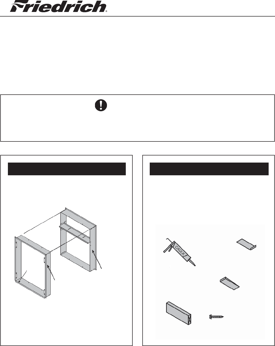
There are two parts to a Wall Plenum:
A) 1-Outside Assembly (Part A)
B) 1-Inside Assembly (Part B)
Step 2: Field Supplied Parts:Step 1: Included Parts
PART A CORRECT ORIENTATION:
● LOUVER ATTACHMENT
FLANGES TOWARD THE BUILD-
ING OUTSIDE, 45°
DRIP LEDGE AT THE BOTTOM.
PART B CORRECT ORIENTATION:
● LARGE OPENING TO BOTTOM
3/4" FLANGE TOWARD THE INSIDE
OF THE BUILDING.
920-069-06 (5-06)
45° Drip
Ledge
Part B
Inside
Plenum
Part A Out-
side Plenum
VERY IMPORTANT!
YOUR WALL PLENUM WILL WORK ONLY IF INSTALLED CORRECTLY. TAKE NOTICE
TO INSTALL IT IN THE CORRECT ORIENTATION AS SHOWN IN THE ILLUSTRATIONS.
ALWAYS FOLLOW LOCAL AND NATIONAL CODES FOR PROPER INSTALLATION.
Caulk, Attachment screws and Flashing
are fi eld supplied. Silicone caulk is
recommended.
VPAWP1-8 adjusts for walls 5.5 - 8.0" thick.
VPAWP1-14 adjusts for walls 8 - 14.0" thick.
Both installations are similar.
Installation Instructions
WALL PLENUM AND LOUVER
For Use With Vert-I-Pak
NOTE: These instructions apply to Vert-I-Pak A Series Units ONLY.
Refer to Chassis Installation/Operation Manual for additional information.
Please read these instructions completely before attempting installation.
Models VPAWP1-8 / VPAWP1-14
2
24 5/8
"
30
7
/
8
"
3
/
4
"
Floor to top
of frame
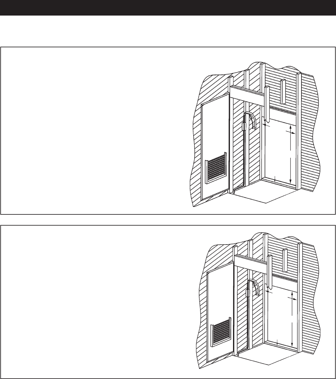
IMPORTANT Determine what model of Vert-I-Pak is to be installed. All 9000, 12000 and 18000 btuh units
must follow the dimensions in Figure A. All 24000 btuh units must follow the dimensions in Figure B.
FIGURE A 9000 / 12000 / 18000 BTU/h
The plenum cut out dimensions are 24 5/8" wide
x 30 7/8" high. The bottom of the rough in open-
ing must be 3/4" from the surface the unit will sit
on.
Measure your outside wall as shown in the
illustration. Cut, frame, and square rough
opening. The Wall plenum has a 3/4" break all
the way around to cover the rough cut opening
or required shim.
FIGURE B 24000 BTU/h
The plenum cut out dimensions are 24 5/8"
wide x 30 7/8" high. The bottom of the
rough in opening must be 1 1/2" from the
surface the unit will sit on.
Measure your outside wall as shown in the
illustration. Cut, frame, and square rough
opening. The Wall plenum has a 3/4" break
all the way around to cover the rough cut
opening or required shim.
24
5
/
8
"
30
7
/
8
"
11/2"
Floor to top
of frame
3" hole in platform for
IMPORTANT THE WALL PLENUM IS NOT DESIGNED TO CARRY STRUCTURAL LOADS. A PROPER
HEADER OPENING MUST BE BUILT INTO THE ROUGH OPENING. THE PLENUM REQUIRES FLASHING,
SHIM AND CAULK FOR A WEATHER-RESISTANT INSTALLATION.
IT IS THE RESPONSIBILITY OF THE CONTRACTOR TO PROPERLY INSTALL THE PLENUM AND MEET
BUILDING CODE REQUIREMENTS.
Step 3: Measure and frame out the outside wall plenum opening
3
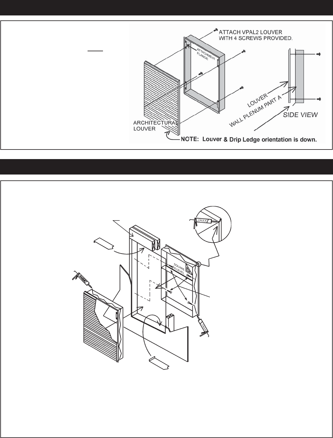
NOTE The VPAL2 Architectural
Louver is best installed onto the
Outside Plenum (Part A) prior to
Wall Plenum installation. Louver
installation is easier at this point,
and it will help keep the Wall Ple-
num square during installation.
Step 4: Install Architectural Louver on the Outside Plenum
After the rough cut opening is prepared, you are ready to assemble the two wall plenum parts. Before
caulking and permanent attachment, dry fi t the outside plenum into the rough opening and check for fi t
and level. Caulk (silicone recommended ) the parts well and insert them into the wall as shown.
A) Apply caulk and insert Outside Part A into the hole.
B) Apply caulk and insert Inside Part B into Part A. Be sure that Part A does not back out of the wall hole.
Step 5: Plenum Installation
Note Proper header and wall penetration must conform to all national and local building codes.
Caulk all 8 fl ange
corners and un-
used holes
Proper Header
Proper
Flashing
Proper Flashing
Proper Caulking
Outside
Wall
Proper
Caulking
Architectural louver VPAL2
mounted on the outside
wall plenum (Part A)
Inside Wall Plenum (Part B)
Install anchor screws approximately
four inches from the top and
bottom of the plenum. Do not make
penetration through the top or
bottom of the plenum
4
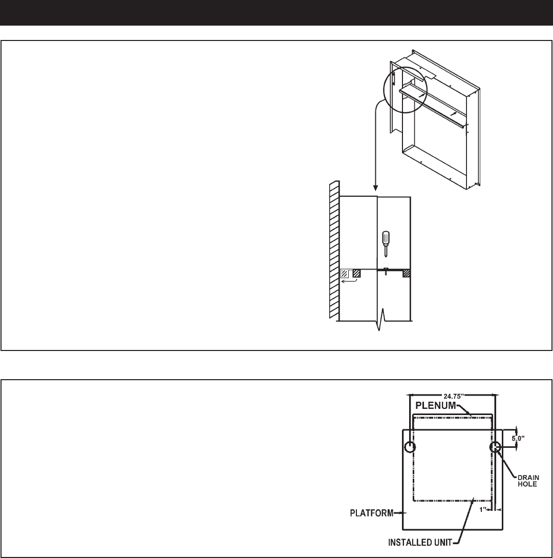
Step 6 - Adjust the Divider
NOTE Let the caulk cure completely before installing
the chassis. This completes the plenum installation.
Adjustment
Loosen the two screws located on the top side of the divider.
Slide the top part of the divider toward the outside until the
sealing strip makes contact with the outdoor louver. Tighten
the divider screws to complete the adjustment.
Condensate Disposal Preparation
for 9000 / 12000 / 18000 Models ONLY
IMPORTANT This step must be performed to ensure that the
chassis installs and seals properly in the wall plenum.
If provisions for condensate disposal are made prior to chassis
installation and the drain is to be located beneath the platform
for the unit, use the accompanying drawing as a guide for cut-
out locations. Only one drain per unit is required.
5
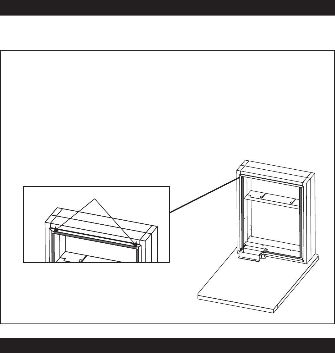
From the inside of the closet locate the top portion of the factory installed weatherseal gasket, arrow A.
Cut the gasket in the upper left and right hand corners of the plenum. Carefully remove the entire top
piece of gasket (See Figure C).
When completed, the wall plenum installation for the 24000 btuh unit should look like fi gure D.
Figure D is shown with the VPDP1 drain pan installed. The drainpan is required for all 24000 buth
units.
Step 7 - Wall Plenum Preparations
IMPORTANT This step must be performed to ensure that the chassis installs and seals properly in
the wall plenum.
Figure C Figure D
Cut here
FOR 24,000 BTU/h MODELS ONLY:
For 24,000 BTU/h models only, continue to next page for VPDP1 installation instructions.
6
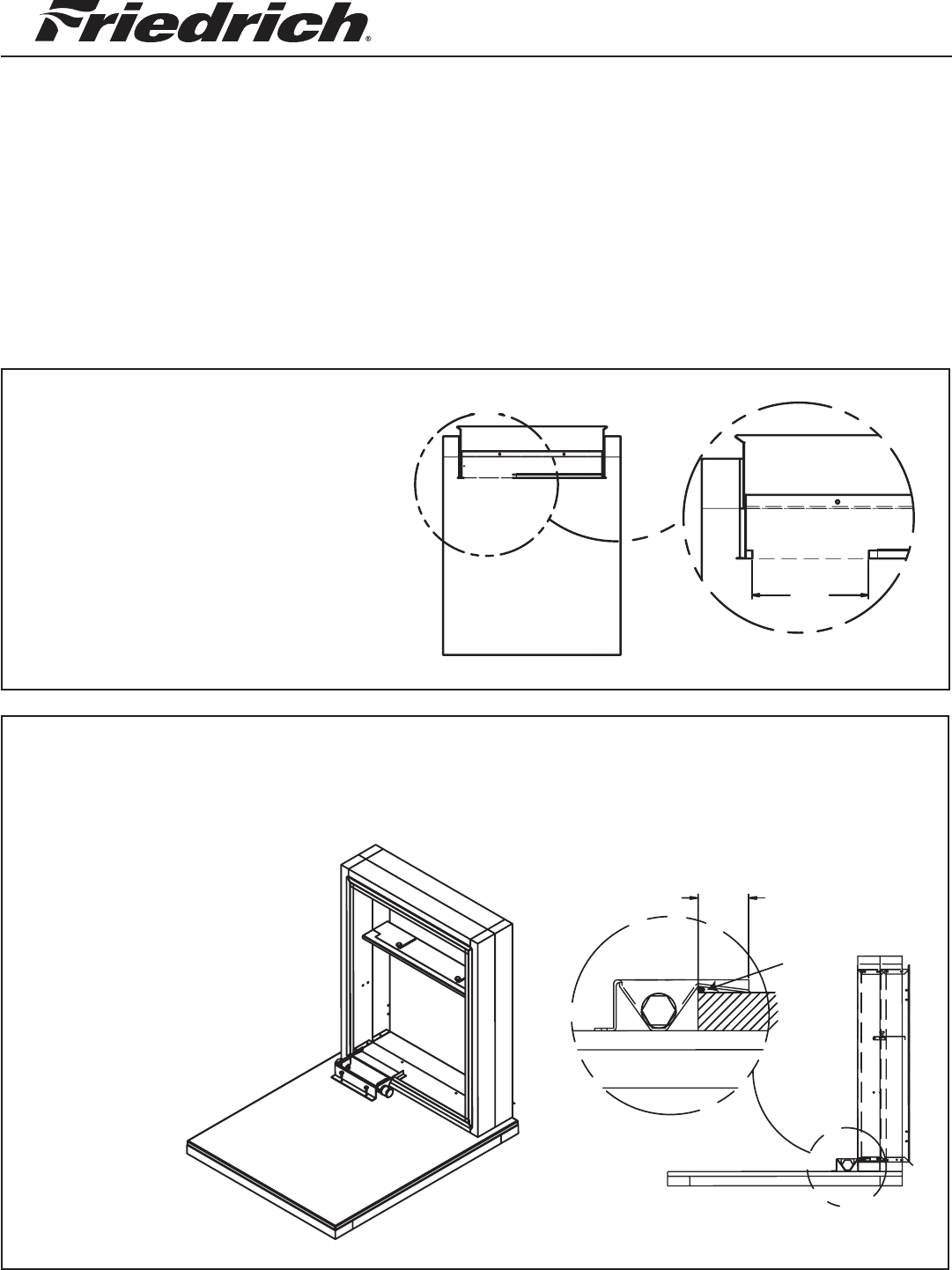
Note: This drain pan must be installed with all VEA24 and VHA24 units.
Remove an 8" portion of the weather
seal gasket from the bottom left sur-
face of the plenum.
To remove: Cut the gasket in the
lower left corner of the plenum. Then
make a second cut 8" from the left
corner. The gasket should peel away
from the plenum leaving a clean
mounting surface (See detail A).
STEP 1: CUT OPENING IN GASKET
Prior to placing the drain pan
into the opening run a 1/4" bead
of sealant the entire width of the
removed gasket. The secondary
overfl ow lip must extend into the
plenum to prevent water leaks.
The pan should be mounted
against the 3/4" fl ange of the
plenum, refer to view A.
STEP 2: SEAL AND SET PAN
A
DETAIL A
8.00
B
2.00
A
Sealant
Installation Instructions
DRAIN PAN
For Vert-I-Pak A Series 24,000 Btuh units only.
Please read these instructions completely before attempting installation.
Models VPDP1
7
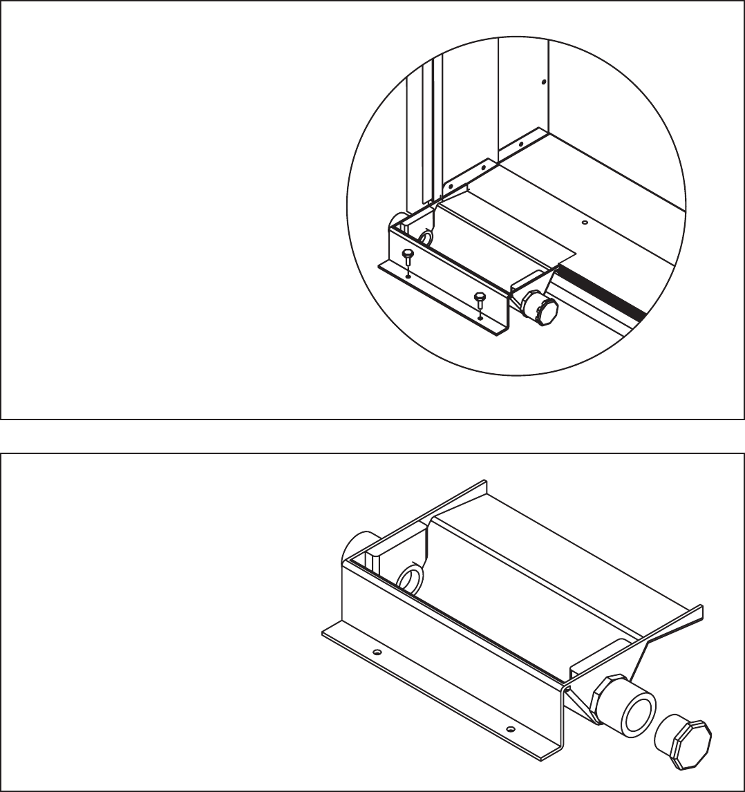
The drain pan comes with both left
and right-hand drain connections
locations. Determine which of the
two connections will be used to
drain the condensate. Then, with
the factory supplied drain plug,
plug the unused opening.
NOTE - proper sealant must be
applied to the connection to pre-
vent leaks.
STEP 4: INSTALL DRAIN PLUG
Attach the drain pan to the closet
fl oor with the appropriate fi eld
supplied hardware.
IMPORTANT - To prevent water
leaks use only the factory sup-
plied mounting holes. NEVER
make penetrations in the drain
pan itself.
STEP 3: INSTALL DRAIN PAN
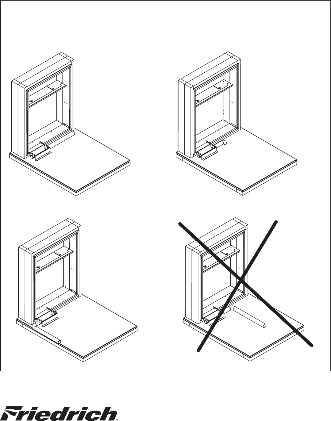
Condensate line routing options are shown below. Choose the one that best suits your installation.
Never run the condensate line as shown in Option 4 below, as the drain line will come into contact
with the factory-installed isolators beneath the unit.
STEP 5: INSTALL DRAIN LINE
IMPORTANT The drain pan and line must be kept free from debris. Prior to installing the chassis ensure that
there are no blockages in the drain pan or line.
Option 1
Run condensate line
to right of unit
Option 3
Run condensate line
to left of unit
Option 2
Run condensate line
beneath unit platform
Option 4
Do not run
condensate line
back toward unit
Friedrich Air Conditioning Co. | www.friedrich.com | Post Offi ce Box 1540 | San Antonio, TX 78295-1540 | 210.357.4400 | Fax 210.357.4480
Printed in the U.S.A. 920-069-06 (5-06)
