Dometic L 2083 User Manual To The 2e2e535b E339 4b60 9a9f A96bfbdad5ac
User Manual: Dometic L-2083 to the manual
Open the PDF directly: View PDF ![]() .
.
Page Count: 1
- Refrigerators & Freezers - Installation
- Refrigerators & Freezers • Operation
- Refrigerators & Freezers • Maintenance
- Refrigerators & Freezers • Trouble-Shooting
- Manufacturer’s Limited Warranty Agreement
- Dometic Corporation – Tundra Schedule of Limited Warranty Allowances
- WARNINGS
- Description of Drawings/Diagrams
English
Revised: 11-04-03
L-0938
❖ ❖
❖ ❖
❖ INSTALLATION • OPERATION
Refrigerators & Freezers
Before installing your Tundra unit,
refer to L-2083: Tundra Installation
Check List.

2 ❖❖
❖❖
❖English
Refrigerators & Freezers • Installation 3
Warnings ................................................................................................................................. 3
Locating the Data Plate 4
Inspection and Handling 4
Electrical Connection 5
DC Only Wiring ........................................................................................................................ 5
AC/DC Wiring (AC/DC Converter) ........................................................................................... 5
Portable Unit Wiring ................................................................................................................. 5
................................................................................................................................................ 5
Portable Units - Special Considerations .................................................................................. 6
DANFOSS Compressor Data .................................................................................................. 6
ABYC Standards - ABYC Guidelines E9 - Direct Current ........................................................ 8
ABYC Standards - ABYC Guidelines E8 - Alternating Current/Amperage ............................... 8
Final Installation Notes 9
Refrigerators & Freezers • Operation 10
Warnings ............................................................................................................................... 10
Temperature Control 10
Rotary Thermostat (Knob Control) ......................................................................................... 10
Digital Thermostat (Solid State Control) ................................................................................ 11
Loading the Appliance 11
Refrigerators & Freezers • Maintenance 12
Defrosting 12
Cleaning 12
Cleaning the Exterior ............................................................................................................. 12
Cleaning the Interior .............................................................................................................. 12
Cleaning the Condenser ........................................................................................................ 12
Refrigerators & Freezers • Trouble-Shooting 13
Appliance Does Not Operate ................................................................................................. 13
Excessive Appliance Noise.................................................................................................... 13
Insufficient Refrigerating Capacity ......................................................................................... 14
Manufacturer’s Limited Warranty Agreement 15
Dometic Corporation – Tundra Schedule of Limited Warranty Allowances 16
WARNINGS 17
Description of Drawings/Diagrams 18-26
Table of Contents
3
Installation ❖❖
❖❖
❖English
Warnings
This section of the manual refers to essential safety Installation information for all
compressor-type refrigerators and freezers (including Portable and Special
Purpose Units), provided by Dometic Corporation.
1. When replacing old appliances, before disposing of the old model, any locking device
with hinging must be removed so that the door cannot be accidentally locked. All
refrigerant must be removed according to current EPA regulations.
2. Unpacking and installation of the unit must be carried out with the utmost care. To
avoid accidental injury use protective gloves, in particular for the models with a remote
condensing unit.
3. After unpacking the appliance ensure that it is not damaged in any way. Notification
of damage must be supplied to the dealer no later than 24 hours from the purchase
date. The appliance must be used exclusively for the conservation of food and drinks.
4. Install the appliance away from any heat sources and allow for sufficient ventila-
tion. (See Installation Section)
5. After installation, wait at least one hour before switching on the appliance. This precau-
tion protects the compressor from shipping mishaps and ensures optimum refrigeration
efficiency.
6. Before connecting the appliance to the power supply, check that the line voltage
corresponds to specifications stated on the appliance dataplate and the compressor.
7. Ensure the safety of operation by proper grounding of the electrical system.
8. After installation, check that the appliance is not standing on the power supply cable.
For any installation problems call your dealer, or call Dometic Corporation at 804-746-1313
or 954-973-2477. Ask for the Tundra service department.
Refrigerators & Freezers • Installation

4
Installation ❖❖
❖❖
❖English
Locating the Data Plate
The dataplate bearing the model and serial number and technical data is located on the
upper right-hand section, inside the appliance (for Portable units, it is located on the inside
of the lid). An additional, identical dataplate is located on the compressor’s electronic
module.
The first three digits of the serial number indicate the Year and Week of manufacture.
Example: If your Serial Number = 0123456 it means:
Inspection and Handling
Ensure that the appliance is not damaged. Any damage resulting from transport must be
reported to the dealer no later than 24 hours after delivery. A notice is printed on the top of
each box, describing the general procedures required.
Handle the appliance with care. Take care when positioning the unit (especially in the case
of refrigerators with remote condensing units), to avoid any obstruction to the connection
lines. Always ensure that the appliance and remote condensing unit (where applicable), are
installed on a dry, flat surface that will not allow it to slide around.
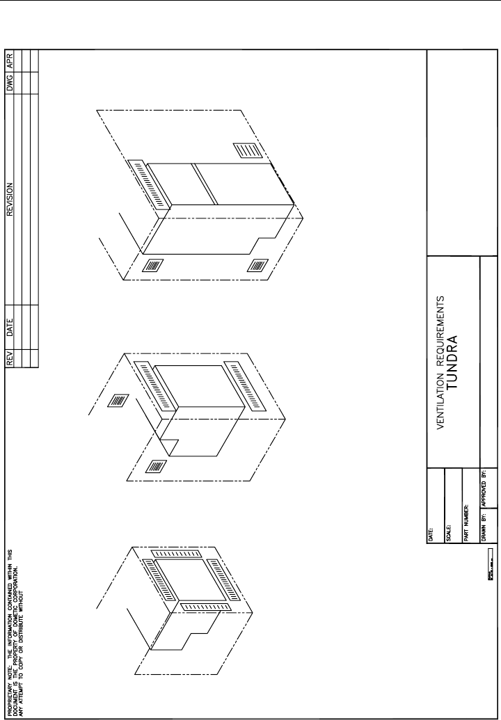
Ventilation is a requirement for the condensing system. Allow for air entry and discharge for
the condensing system. Air entry and discharge requires a minimum of 50 total sq. inches
each. (A T-80 unit requires a minimum of 75 total sq. inches for air entry and discharge.)
A lower entry, and upper discharge is preferred. (See Fig. 5, page 21)
When installing the appliance in campers, motorhomes etc., install air vents connected
directly to the outside.
Install appliance away from heat sources in a dry and well-ventilated area. Avoid direct
contact with water. The appliances are not waterproof.
0 = Year 2000 12 = 12th Week of the Year 3456 = Sequential Unit Number

5
Installation ❖❖
❖❖
❖English
Electrical Connection
Before connecting the appliance to the power supply, check that the line voltage corre-
sponds to the indications on the appliance rating plate and those of the compressor plate.
This appliance complies with EC directive 89/336 governing radio suppression.
Noise emission levels are maintained below 70 dB(A).
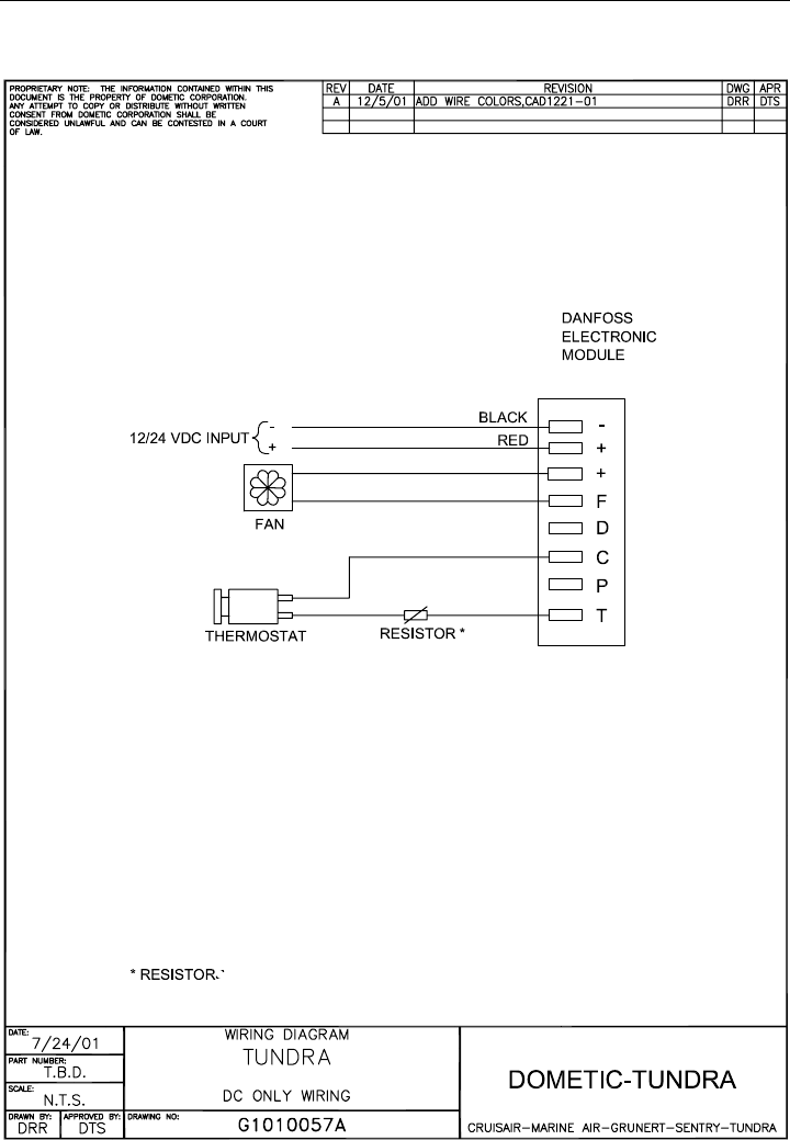
DC Only Wiring
For Direct Current (DC) refrigerators, connect the appliance to the DC distribution center. A
circuit breaker of 15 Amps (maximum) must be used if the system is 12VDC, and 10 Amps
(maximum) if the system is 24VDC. Make sure that proper polarity is maintained at all
times. Check that all grounding systems are in good working order. The appliance must be
wired and grounded in accordance with the ABYC Guideline E9. (See ABYC Guide-
lines E9 pg. 8)
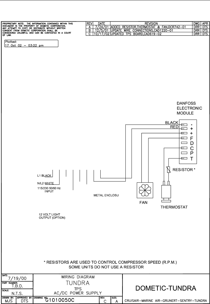
AC/DC Wiring (AC/DC Converter)
If the appliance is equipped with an AC/DC converter, then both AC and DC power may be
used. The converter functions by converting AC power into DC power for the compressor.
When the converter is connected to both AC and DC, and the AC power is on, then the unit
will run on the AC power. However, if the AC power is lost, the unit will run on the DC power.
If both types are to be used, connect the DC wiring to the DC distribution panel, and the AC
wiring to the AC distribution panel, following ABYC guidelines. The converter may be
connected to either AC or DC power only, if so desired.
For the DC wiring, follow the same instructions as stated in the ‘DC Only Wiring’ section. For
the AC wiring, use a 10 Amp circuit breaker (maximum). Make sure that proper polarity is
maintained at all times. Check that all grounding systems are in good working order. The
appliance must be wired and grounded in accordance with the ABYC Guideline E8.
(See ABYC Guidelines E8, pg. 8)
Portable Unit Wiring
The TPD23/AC models have AC and DC receptacles that are prewired to the unit. The
TPD23 model has only the DC receptacle prewired. The TPD23AC model has both the AC
and DC receptacles prewired.
Each unit comes equipped with the mating connector and cable as required (DC cable with
TPD23 and both AC and DC cables with TPD23AC). These must be connected to their
respective power sources as described in the wiring instructions listed above.

6
Installation ❖❖
❖❖
❖English
Portable Units - Special Considerations
Since Portable units can be used in a variety of applications, and connected to a variety of
power sources, the following must be considered:
• Cigarette lighters may not provide sufficient voltage and power to start and
operate a portable unit. The unit may need to be wired separately from the lighter
receptacle.
• Many DC outlets in vehicles (i.e. cigarette lighters, power outlets, etc.), are not
powered when the ignition switch is turned to “Off”. Check available outlets for this
condition before leaving the unit unattended.
• Some DC outlets or receptacles remain powered when the ignition switch is
turned OFF, but do not have enough voltage to restart the compressor when
required. Check for this condition before leaving the unit unattended.
• Power outlets or receptacles that are connected directly to the battery, and have a
higher amp fused circuit (40 amps vs. 15-20 amps) will generally restart the
compressor with the ignition switch turned OFF.
Caution must be taken when the unit is left unattended under these
circumstances, as the battery will continue to drain down as the
compressor cycles and runs. This can cause the battery voltage to
drop too low to restart the vehicle’s engine. The cut-out voltage
that protects the compressor is 10.4 volts. Therefore, if the unit is
to be operated for long periods of time without replenishing the
battery, another power source may need to be provided or the unit
should be shut off, and the contents removed.
• Ambient conditions, wire sizes and battery quality can affect operation.
DANFOSS Compressor Data
Voltage Range
12V systems: From 10.4V to 17V
24V systems: From 22.8V to 31.5V
The electronic unit will calibrate automatically to the applied voltage. This means that if the
battery voltage is less than 17V, the electronic unit assumes that it is working in a 12V
system. If the voltage is higher than 17V, the electronic unit assumes that it is working in a
24V system. Consequently, the compressor does not run at power supply voltages between
17V and the desired battery protection cut-out voltage of 22.8V, for 24V systems.
Protection Systems
The Danfoss compressor protection system facilitates protection against compressor
overload and start failure, fan overload and electronic unit overheating as well as destruc-
tive battery discharge. When an overload protection is activated, the compressor enters a
cycle in which it makes start attempts at approximately 60 second intervals until a success-
ful start is achieved.

7
Installation ❖❖
❖❖
❖English
Overload Protections
The compressor overload and start protection cuts off power to the compressor if the
compressor speed drops below approximately 1,900 rpm, or if this motor speed is not
reached during the start sequence. Possible reasons for overload protection activating
could be too high refrigeration system pressures during operation or lack of pressure
equalizing at start.
The fan overload protection stops the compressor if the fan current exceeds 0.5 A
(avg)
or 1 A
(peak)
.
An overheating of the electronic unit heat sink will cause the compressor to stop. Restart will
occur automatically when a normal temperature has been reached. If a fan is installed, it will
continue to run when the compressor stops, due to overload or electronic unit overheating.
Voltage Protection
If a voltage outside any operational range is applied to the electronic unit, the compressor
does not start, or it stops if the voltage limit is exceeded during operation. The compressor
will restart automatically, approximately 1 minute after the supply voltage has reached the
reset voltage within the range in question.
Battery Protection
The Danfoss electronic unit provides protection as follows:
12V cut-out 12V cut-in 24V cut-out 24V cut-in
10.4 11.7 22.8 24.2
Standard Battery Protection Settings
8
Installation ❖❖
❖❖
❖English
ABYC Standards - ABYC Guidelines E8 - Alternating Current/Amperage
Temperature Rating of Conductor Insulation (Guidelines when using an AC/DC Converter)
60°C 75°C 80°C 90°C 105°C 125°C 200°C
(140°F) (167°F) (176°F) (194°F) (221°F) (257°F) (392°F)
Outside
Conductor Outside Inside Outside Inside Outside Inside Outside Inside Outside Inside Outside Inside or Inside
Size Engine Engine Engine Engine Engine Engine Engine Engine Engine Engine Engine Engine Engine
(AWG) Spaces Spaces Spaces Spaces Spaces Spaces Spaces Spaces Spaces Spaces Spaces Spaces Spaces
18 7.0 4.1 7.0 5.3 10.5 8.2 14.0 11.5 14.0 11.9 17.5 15.6 17.5
16 10.5 6.1 10.5 7.9 14.0 10.9 17.5 14.4 17.5 14.9 21.0 18.7 24.5
14 14.0 8.1 14.0 10.5 17.5 13.7 21.0 17.2 24.5 20.8 28.0 24.9 31.5
12 17.5 10.2 17.5 13.1 24.5 19.1 28.0 23.0 31.5 26.8 35.0 31.2 38.5
10 28.0 16.2 28.0 21.0 35.0 27.3 38.5 31.6 42.0 35.7 49.0 43.6 49.0
8 38.5 22.3 45.5 34.1 49.0 38.2 49.0 40.2 56.0 47.6 63.0 56.1 70.0
6 56.0 32.5 66.5 49.9 70.0 54.6 70.0 57.4 84.0 71.4 87.5 77.9 94.5
4 73.5 42.6 87.5 65.6 91.0 71.0 94.5 77.5 112.0 95.2 119.0 105.9 126.0
3 84.0 48.7 101.5 76.1 105.0 81.9 108.5 89.0 126.0 107.1 136.5 121.5 147.0
2 98.0 56.8 119.0 89.3 122.5 95.6 126.0 103.3 147.0 125.0 157.5 140.2 168.0
1 115.5 67.0 136.5 102.4 147.0 114.7 147.0 120.5 171.5 145.8 185.5 165.1 196.0
0 136.5 79.2 161.0 120.8 171.5 133.8 171.5 140.6 199.5 169.6 213.5 190.0 227.5
00 157.5 91.4 185.5 139.1 199.5 155.6 199.5 163.6 231.0 196.4 248.5 221.2 259.0
000 182.0 105.6 217.0 162.8 231.0 180.2 231.0 189.4 269.5 229.1 287.0 255.4 301.0
0000 210.0 121.8 252.0 189.0 269.5 210.2 269.5 221.0 311.5 264.8 332.5 295.9 357.0
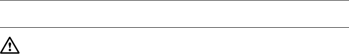
ABYC Standards - ABYC Guidelines E9 - Direct Current
Conductor Sizes For 3 Percent Drop in Voltage

9
Installation ❖❖
❖❖
❖English
Final Installation Notes
• For all appliances, AVOID the use of any electrical adapters or extension cords.
• After installation, allow the appliance to sit for at least one hour before starting.
•The manufacturer assumes no responsibility for any injuries or damage caused
by noncompliance with any of the installation regulations.

10
Operation ❖❖
❖❖
❖English
Warnings
This section of the manual refers to essential safety Operation information for all
compressor-type refrigerators and freezers (including Portable and Special
Purpose Units) provided by Dometic Corporation.
•
Before carrying out any maintenance or cleaning operations, disconnect appliance from
power supply via the circuit breaker.
•
Do not put glass containers holding liquids in the freezer compartment.
•
Dispose of packaging material in accordance with local laws for sorted waste recycling.
For any operational problems call your dealer, or call Dometic Corporation at 804-746-1313
or 954-973-2477. Ask for the Tundra service department.
Temperature Control
Each appliance is fitted with a manual thermostat which automatically maintains set
temperatures. There are two (2) types of thermostats. Operation instructions for each are
included here.
Rotary Thermostat (Knob Control)
(See Fig. 2, page 19)
1. Select desired temperature by means of the adjustment knob.
2. The refrigerator is STARTED by turning the knob clockwise. It clicks “ON.” Temperature
setting range is shown using a band that thickens in the clockwise direction. The thicker
the band, the colder the setting.
Some models are fitted with thermostats with different temperature scale
markings than those described above or displayed in Fig. 2. In this case,
the temperature is still lowered by turning the knob clockwise.
3. To turn OFF the unit, turn the knob to “0” or “OFF.” It clicks “OFF.”
Refrigerators & Freezers • Operation

11
Operation ❖❖
❖❖
❖English
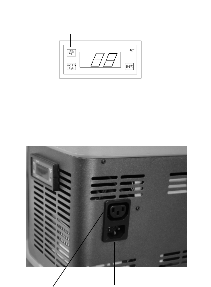
Digital Thermostat (Solid State Control)
(See Fig. 3, page 20)
• The Digital Thermostat AUTOMATICALLY turns ON when power is applied to unit.
• The thermostat displays the interior temperature constantly.
To access, and/or change the Setpoint temperature, do the following:
1. Press the “set” Button to display the Setpoint temperature. The Setpoint is
changed with the “up” and “down” Arrow Buttons. The last entered Setpoint will stay in
memory. The control automatically returns to NORMAL mode (displaying the interior
temperature) within 5 seconds.
2. Press the “up” Button to INCREASE Setpoint temperature. When held down for a
few seconds, the change rate accelerates.
3. Press the “down” Button to DECREASE Setpoint temperature. When held down
for a few seconds, the change rate accelerates.
Loading the Appliance
All materials exposed to contact with food comply with EC directive 89/109.
Once the thermostat is set to a desired temperature, allow the unit to RUN at least
12 hours (24 hours for best results) before loading it with goods.
Food Storage Time Position In Appliance
Meat or fish properly 2 to 3 days On the rack under the freezer
wrapped in plastic compartment
Eggs 1 week Use door compartment
Butter, margarine 1 week Use door compartment
Cooked food, cakes and
soups (in sealed 3 to 4 days On the lowest rack in the refrigerator
containers and cooled)
Cold cuts, cheese,
fresh pasta, pastries,
cream, tomatoes, 3 to 4 days On any rack
puddings, chocolates,
lard
Fruit and vegetables 1 week In the bottom of the refrigerator
For proper food storage and conservation refer to the table below:

12
Maintenance ❖❖
❖❖
❖English
Defrosting
Defrosting should be carried out whenever the frost layer exceeds a thickness of 1/8 of an
inch. This is necessary to guarantee efficient refrigeration and to avoid excessive power
consumption. Excess frost buildup will effect the appliance’s performance.
To completely defrost, turn the appliance OFF. Keep the door/lid open to minimize the
defrosting time.
Do not attempt to remove the frost layer using any sharp metal instruments. This could
pierce the appliance plate and cause irreparable damage to the appliance.
After defrosting, dry the entire interior surfaces, and then turn the appliance ON.
Cleaning
Before cleaning, disconnect the appliance from the power supply. If necessary, remove the
plug from the power socket.
Cleaning the Exterior
Clean the exterior with warm and then with cold water. Dry with a soft cloth. Avoid use of
abrasive products.
Cleaning the Interior
Remove racks, containers, and ice trays. Clean the interior using warm water mixed with
baking soda or vinegar. Rinse and dry carefully with a soft cloth. Do not use abrasive
products, detergents or soap. In the case of prolonged disuse, to avoid the formation of
mold or unpleasant odors, remove plug from socket, empty the unit completely, clean the
interior, and leave the door/lid ajar.
Cleaning the Condenser
Clean the condenser at least once a year using a vacuum cleaner or dry brush.
Do not clean with sharp objects.
Refrigerators & Freezers • Maintenance

13
Trouble-Shooting ❖❖
❖❖
❖English
Refrigerators & Freezers • Trouble-Shooting
A. Appliance Does Not Operate
Check that:
1. The thermostat is not set to “STOP” or “OFF”.
2. The electrical system circuit-breaker for the appliance is “ON”.
3. The fuse between the electronic control unit and the power source has not blown.
4. The power supply cable is not faulty, loose or poorly connected.
5. The battery is delivering sufficient power. If the battery voltage is less than 10.4V (on a
12VDC system) or 22.8V (on a 24VDC system), the unit will not operate.
6. The voltage on the electronic control unit terminal board corresponds to that of the
battery. If there is a voltage drop of over 0.2-0.4V check that:
a. The size of the cable connecting the battery to the electronic control unit corre-
sponds to specifications (see ABYC Guidelines).
b. All connection points in the power supply are properly tightened.
c. There are no signs of oxidation on the battery poles and contact points.
7. If an AC/DC converter is being used, check that:
a: The AC power source is “ON”.
b. The circuit board terminals are properly connected.
c. Output voltage to the appliance is sufficient.
B. Excessive Appliance Noise
Check that:
1. The appliance and refrigerating unit are positioned on flat surfaces.
2. The appliance is not touching other objects that may cause vibration.
3. The refrigerant lines at the back of the unit (if applicable) are not touching or vibrating
against the appliance.

14
Trouble-Shooting ❖❖
❖❖
❖English
C. Insufficient Refrigerating Capacity
Check that:
1. The door/lid is sealed properly.
2. The appliance is not positioned close to heat sources.
3. The appliance and remote refrigerating unit (if applicable) are sufficiently ventilated.
4. Excess frost has not accumulated on the evaporator.
5. Dust has not blocked the condenser.
6. The fan rotates freely (in forced air models).
7. The appliance is not over-full.
If, after checking the above, the appliance still does not function, call your service
dealer or Dometic Corporation at 804-746-1313 or 954-973-2477. Ask for the Tundra
service department.

15 ❖❖
❖❖
❖English
Manufacturer’s Limited
Warranty Agreement
The following warranty is extended to cover Tundra products supplied by Dometic Corpora-
tion and is subject to qualifications indicated. Dometic Corporation warrants for the periods
set forth below that products manufactured or supplied by it will be free from defects in
workmanship and material, provided such products are installed, operated, and maintained
in accordance with Dometic Corporation written instructions.
All implied warranties, including merchantability and fitness for a particular purpose, are
limited to the terms and periods of warranty set forth below and, to the extent permitted by
law, any and all implied warranties are excluded.
Note: The warranty described below is for all segments of the marine pleasure boat
industry only. There are significant timing issues for other industries. Consult
your source of purchase if you have a unit installed into other applications
(trucks, recreational vehicles, etc.). Warranties may be tied to chronological
events, mileage, etc., and provide for different coverages.
New units are warranted for a period of two (2) years from the date of installation for all
parts, not to exceed three (3) years from the date of manufacture.
Labor will be paid as outlined in the Schedule of Limited Warranty Allowances for re-
moval and reinstallation of such components for a period of one (1) year from the date of
installation. OEM installed equipment warranties begin with the purchase of the vessel or
vehicle, not from the date of installation. Warranty will be paid in accordance with our estab-
lished schedule of allowances. Compensation for warranty repairs is only made to Dometic
Corporation authorized service companies.
Dometic Corporation will repair or replace, at its option, components found to be defective
due to faulty materials or workmanship, when such components, examined by an autho-
rized service dealer or a factory service representative, are found to have a defect for which
the company is responsible. Replacement components are warranted for the duration of
the remaining warranty period in effect on the original component.
The limited warranty is extended in lieu of all other warranties, agreements or obligations,
expressed or implied, concerning Tundra’s components. This warranty is extended only to
the original purchaser and is not transferable. This warranty shall be governed by the laws
of the State of Florida and gives the original first end user definite legal rights.
This warranty does not cover damages incidental and/or consequential to the failure of
Dometic Corporation’s equipment including but not limited to the folloiwng: normal wear,
accident, misuse, abuse, negligence, improper installation, lack of reasonable and neces-
sary maintenance, alteration, civil disturbance or acts of God.
No person or dealer is authorized to extend any other warranties or to assume any other
liabilities on Dometic Corporation’s behalf, unless made or assumed in writing by an officer
of Dometic Corporation.

16 ❖❖
❖❖
❖English
Dometic Corporation – Tundra Schedule of
Limited Warranty Allowances
This schedule lists the maximum Dometic Corporation allowance for the repairs listed
below. Items which exceed the scheduled allowances require prior approval. Sales
tax, duty, mileage charges, tolls, phone calls, etc. are not covered by warranty and are
the responsibility of the customer. If more than one repair is performed during the same
visit, Dometic Corporation will pay 100% of the first covered repairs and 50% for all
others. This warranty does not cover incidental and/or consequential items to the failure
of Tundra’s refrigeration equipment.
CUSTOMER RESPONSIBILITIES
1. Verify the product’s purchase date for warranty purpose.
2. Pay for normal operational maintenance, cleaning or adjustments.
3. Pay for damage repairs resulting from unauthorized modifications, improper electrical
supply or damage by fire, storm or other acts of God.
4. Pay for premium labor rates, excessive mileage or miscellaneous tools
and material charges not listed, and additional labor charges resulting from the
inaccessibility of the unit for service.
Labor Allowance Labor Allowance
Warranty Service Performed Marine Industry Trucking Industry
Unit change out 3.5 hours 1.5 hours
Thermostat change out 2.5 hours 1.0 hours
Electronic Module change out 2.5 hours 1.5 hours
Door change out 2.0 hours 1.0 hours
Power supply change out 2.5 hours 1.0 hours
Resistor (speed setting) change out 2.0 hours 0.5 hours
Fan Motor change out 2.5 hours 1.5 hours
Door lock change out 1.5 hours 0.5 hours

17 ❖❖
❖❖
❖English
WARNING
Dometic Corporation, manufacturers of Cruisair, Grunert, Marine Air, Sentry and Tundra Products, makes the following
safety warnings concerning the application, installation, use and care of its products. Although these warnings are
extensive, there may be specific hazards which may arise out of circumstances which we have not outlined herein. Use
this as a guide for developing an awareness of potential hazards of all kinds. Such an awareness will be a key factor in
assuring your SAFETY and comfort.
ELECTRICITY - Many Dometic products operate on 115, 230 or 440 volt AC power and/or 12/24 volt DC power. Such
voltages can be LETHAL; therefore, the chassis, cabinets, bases, etc., on all components must be grounded together
and connected to the vessel's or vehicle’s grounding system. Sparks can occur as switches, thermostats and relays
open and close in the normal operation of the equipment. Since this is the case, ventilating blowers for the removal of
hazardous fumes or vapors should be operated at least 5 minutes before and during operation of any Dometic product or
group of Dometic products. All electrical connections must be covered and protected so accidental contact cannot be
made by persons using the equipment, as such contact could be LETHAL.
ELECTROLYSIS - Electrical leakage of any component can cause electrolytic deterioration (electrolysis) of thru-hull
components which could result in leakage serious enough to sink a vessel which could result in loss of life. All Dometic
components must be kept clean and dry and checked periodically for electrical leakage. If any electrical leakage is
detected, the component should be replaced or the fault causing the leakage corrected before the component is put
back into service.
GAS - CRUISAIR, MARINE AIR, GRUNERT and TUNDRA components utilize R134a refrigerant, R409A or R404A,
R417A, R407C and R22. These are non-toxic, non-flammable gases. However, these gases contain no oxygen and will
not support life. Refrigerant gas tends to settle in the lowest areas of the compartment. If you experience a leak,
evacuate all personnel, and ventilate area. Do not allow open flames in the area of leaks because refrigerant gas, when
burned, decomposes into other potentially LETHAL gases. Refrigerant components operate at high pressure and no
servicing should be attempted without gloves, long-sleeved clothing and eye protection. Liquid refrigerant gas can cause
severe frost burns to the skin and eyes.
VENTILATION - CRUISAIR, MARINE AIR, GRUNERT and TUNDRA components are designed to move air through a heat
exchanger by a blower or propeller fan. This design necessarily produces a suction on one side of the air handling
component and a pressure on the other side. Air handling components must be installed so that the suction-pressure
action does not: (1) pressurize an area to the extent that structural failure occurs which could cause harm to occupants
or bystanders, or (2) cause a suction or low pressure in an area where hydrogen gas from batteries, raw fuel vapor from
fuel tanks, carbon monoxide from operating propulsion engines, power generators or heaters, methane gas from sewage
holding tanks, or any other dangerous gas or vapor could exist. If a unit is installed in such a manner that allows
potentially lethal gases or vapors to be discharged by the air handling unit into the living space, this could result in loss
of life.
Maximum protection against the introduction of dangerous gases or vapors into living spaces can be obtained by
providing living spaces which are sealed from all other spaces by use of airtight bulkheads and decks, etc., and through
the introduction of clean air into the living space. Bear in mind that the advent of air conditioning, whether it be for
cooling or for heating, naturally leads to the practice of closing a living space tightly. Never close all windows and doors
unless auxiliary ventilating systems, which introduce clean outside air into the living space, are used. Always leave
enough window and door openings to provide adequate ventilation in the event potentially lethal gases or fumes should
escape from any source.
CONDENSATE - All cooling units produce water condensate when operating on the cooling cycle. This water must be
drained from the cooling unit overboard. If condensate is allowed to drip on a wooden structure, rotting or decay and
structural failure may occur which could result in loss of life. If condensate is allowed to drip on electrical components,
deterioration of the electrical components could result in hazardous conditions. When an air conditioning system is in
operation, condensate drains may be subjected to negative pressure. Always locate condensate drains as far as
possible from points where engine waste and other dangerous gases are exhausted so no such dangerous gases can be
drawn into the condensate drains.
Warning
Never sleep in a closed area on a boat or vehicle when any equipment, which functions as a result of the combustion of
a volatile fuel, is in operation (such as engines, generators, power plants, or oil-fired heaters, etc.) At any time, the
exhaust system of such devices could fail, resulting in a build-up of LETHAL gases within the closed area.
Rev. Date: 9-26-03 Tundra Version

18 ❖❖
❖❖
❖English
Description of Drawings/Diagrams
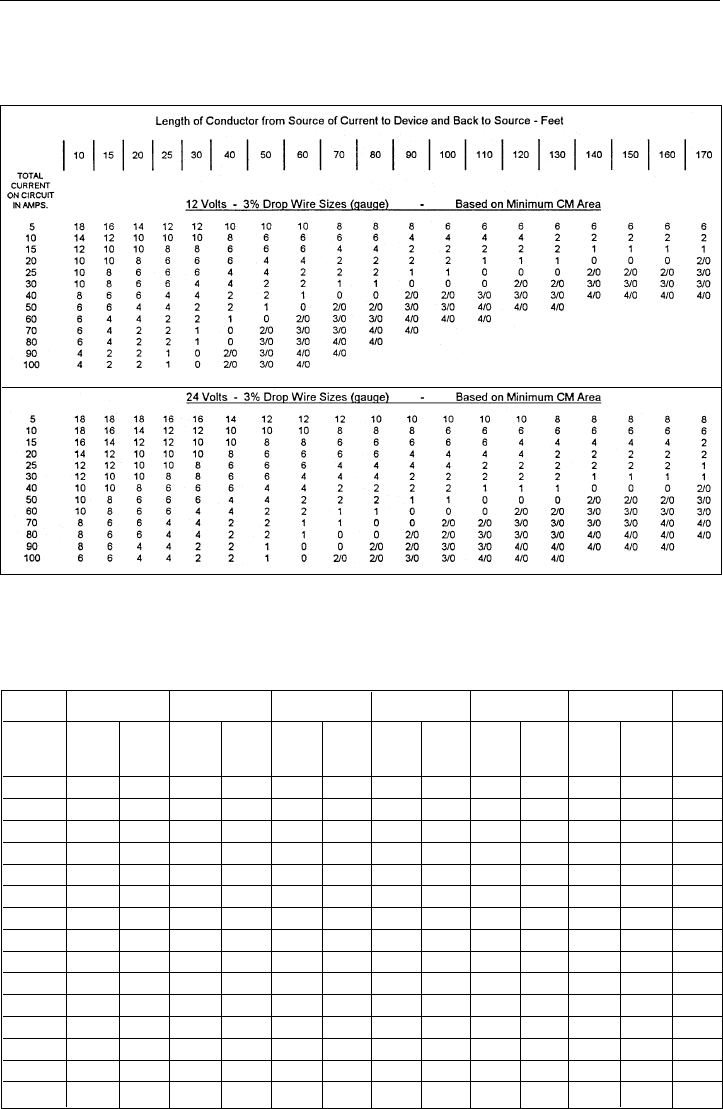
Fig. 1 Description of an Appliance (1 - 8)
1. Mounting Flange Assembly 5. Glass shelf
2. Freezer Compartment w/ Door 6. Door Shelves/Bottle Compartments
3. Condensation Drain Pan 7. Positive Locking Door (Nautic Lock)
4. Vinyl Coated Wire Shelf(s) (Adjustable) 8. Thermostat
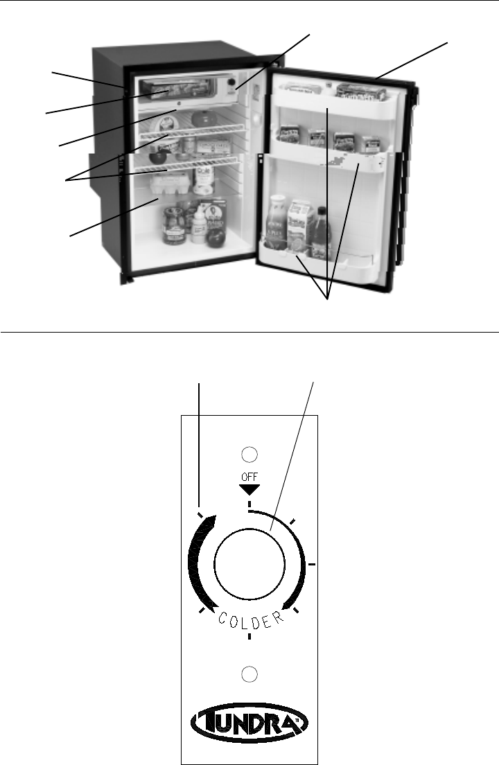
Fig. 2 Rotary Thermostat
1. Coldest Setting
2. Adjustment Knob, Turn Clockwise
Fig. 3 Digital Thermostat
1. “up” Button
2. “down” Button
3. “set” Button
Fig. 4 Portable Unit Cable with 12V Plug
Fig. 5 G1030011A Tundra Ventilation Requirements
Fig. 6 G1010057A DC Only Wiring Diagram
Fig. 7 G1010050C TPS AC/DC Power Supply Wiring Diagram
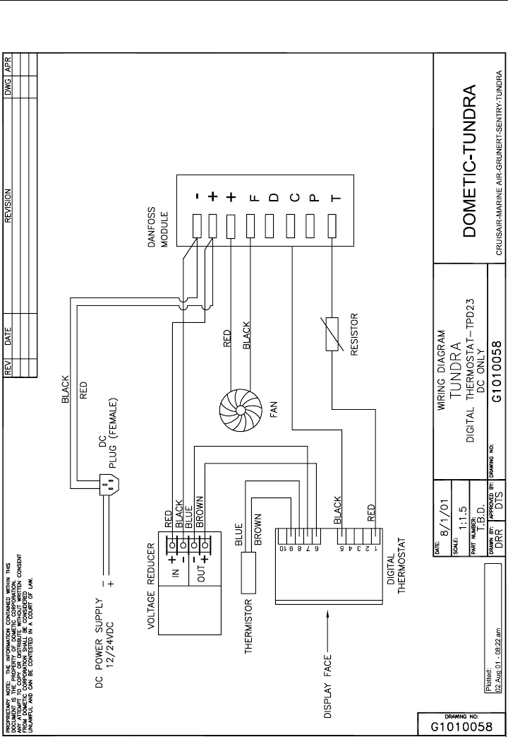
Fig. 8 G1010058 Digital Thermostat - TPD23 (DC only) Wiring Diagram
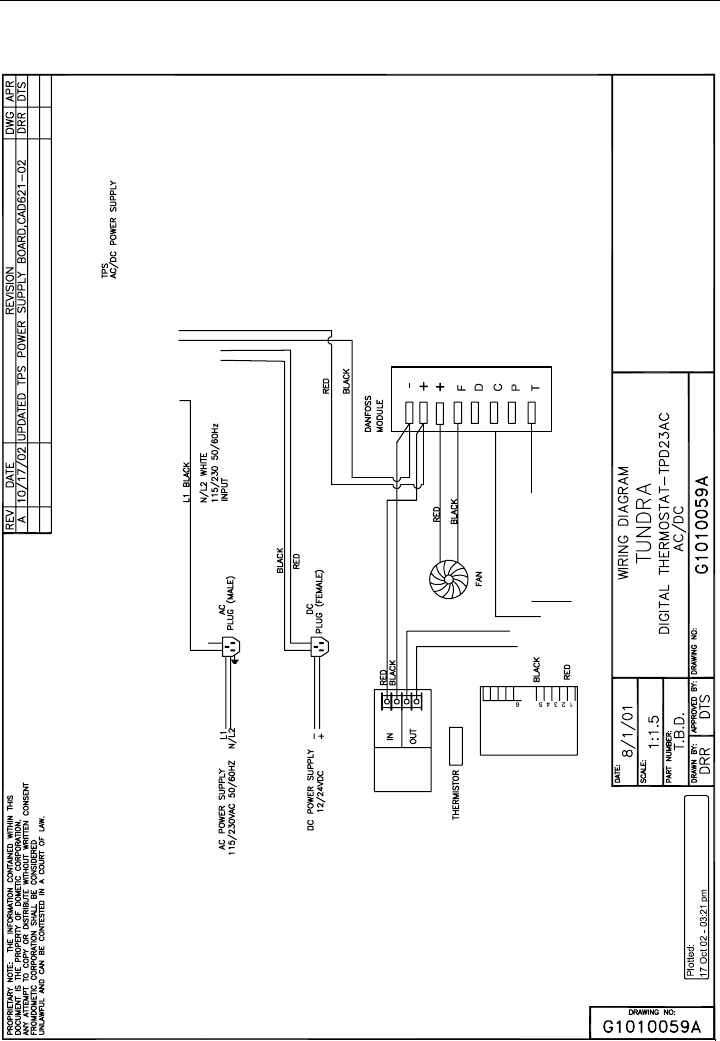
Fig. 9 G1010059A Digital Thermostat - TPD23AC (AC/DC) Wiring Diagram
Fig. 10 G1030029 Latch Redesign Schematic
19
Fig. 2 Rotary Thermostat
Fig. 1
2. Adjustment Knob.
Turn Clockwise
1. Coldest Setting
4.
1.
2.
3.
5.
6.
8. 7.
20
Fig. 4 Portable Unit Power Conections
3. “set”
Button
2. “down “
Button
1. “up”
Button
AC Power
Connector
DC Power
Connector
Fig. 3 Digital Thermostat
21
22
Fig. 6 DC Only Wiring Diagram
23
Fig. 7 TPS AC/DC Power Supply
24
Fig. 8 Digital Thermostat - TPD23 (DC only) Wiring Diagram
25
Fig. 9 Digital Thermostat - TPD23AC (AC/DC) Wiring Diagram

26
Fig. 10 Latch Redesign Schematic

27

L-0938
Dometic Corporation
2000 N. Andrews Ave. Ext. • Pompano Beach, FL 33069-1497 USA
954-973-2477 • Facsimile: 954-979-4414 • www.tundra.cc
P.O. Box 15299 • Richmond, VA 23227-0699 USA
804-746-1313 • Facsimile: 804-746-7248
Place
Data Label
Here
