DoorKing M1815 706 A Door King RS232 To RS422 Assembly Wiring Diagram 1815 C 5 15
User Manual: DoorKing DoorKing RS232 to RS422 Assembly Wiring Diagram Wiring Diagram
Open the PDF directly: View PDF ![]() .
.
Page Count: 1
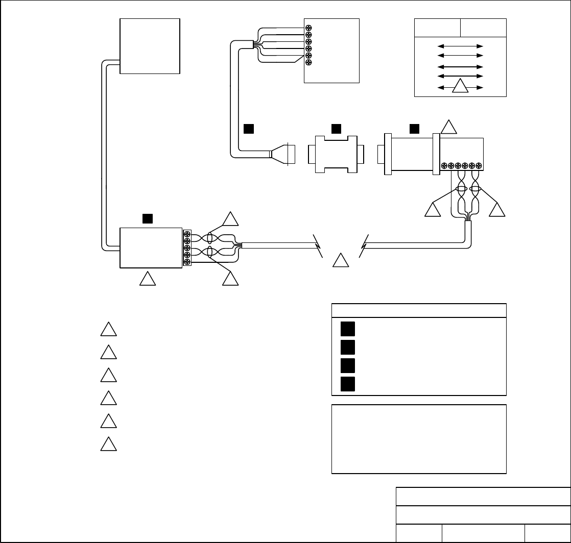
T +
T -
R +
R -
GND
+5 VDC
RS422
Converter
Null
Modem
1833, 1834
1835, 1837
1838
RS232
Terminals
1
2
3
4
5
6
Red
White
Brown
Shield
Green
Black
PC
USB Port
CAT 5
Up to 4000 Ft
1
2
1 2
4
6
A B C
D
This assembly will only work with the Remote Account
manager software version 6.0 or later.
1833, 1834, 1835 and 1837 circuit boards must be REV I
or higher.
1838 circuit board must be REV H or higher.
Notes
5
1Transmit data terminals + and - connect to Receive
data terminals + and - respectively and are twisted.
Receive data terminals + and - connect to Transmit
data terminals + and - respectively and are twisted.
2
3GND wire is not twisted with any other wires.
4+5 VDC terminal is not used.
5Set all switches on the back of the USB Adapter to the
LEFT.
6CAT 5 Wire is not supplied.
RS422
USB Adapter RS422
Converter
T -
T +
R -
R +
GND
R -
R +
T -
T +
GND
Twisted Pair
Twisted Pair
3
T-
T+
R-
R+
GND
RS422
USB Adapter
DOORKING, INC., INGLEWOOD, CA 90301
Date: Dwg. No. Rev.
Title:
5/16 C
1815-706
RS232 to RS422 Assembly
Wiring Instructions
DRS422 USB Adapter (Includes USB cable and CD
with necessary drivers) P/N 1815-705
CRS422 Converter P/N 1815-704
BNull Modem P/N 1815-703
ARS232 Cable P/N 1818-040
RS232 to RS422 Assembly P/N 1508-055
