DoorKing 2019 Door King Price Book 2019doorkingpricebook
User Manual: DoorKing 2019 DoorKing Price Book Price Book
Open the PDF directly: View PDF ![]() .
.
Page Count: 180 [warning: Documents this large are best viewed by clicking the View PDF Link!]
- Price Schedule Cover 2019
- Terms & Conditions_1-7-19
- General Information
- Authorized Distributors & Dealers
- Terms
- Pricing
- Quotations
- Taxes and Fees
- Will Call
- Shipping
- Drop Shipments:
- 3rd Party Shipments (drop ship policy applies)
- Fees
- Custom Orders
- Special Orders
- Warranty Claims
- Returns
- Substitutes
- Force Majeure
- Unenforceable Provision
- Governing Law
- Repairs
- Repair Warranty
- Advance Replacements
- Obsolete Board Repair and Replacement (Upgrade) Information
- Shipping Charges
- Section A1_Jan_2019_1-16_19
- This Price Schedule is effective January 7, 2019.
- UL 325 – August 2018 Update
- Blank Page
- Table of Contents
- 1175 Overhead Operator
- 1175 Overhead Operator
- 1601 Barrier Gate Operator
- 1601 Barrier Gate Operator
- 1602 Barrier Gate Operator
- 1602 Barrier Gate Operator
- 1603 Barrier Gate / Auto-Spikes
- 1603 Barrier Gate / Auto-Spikes
- Model 1610
- Traffic Control
- Overhead / Barrier Operator Parts & Replacement Items
- Blank Page
- 6005, 6003, 6004, 6400 Operators
- 6005, 6003, 6004, 6400 Operators
- 6050 / 6100 Swing Gate Operators
- 6050 / 6100 Swing Gate Operators
- 6300 Swing Gate Operators
- 6300 Swing Gate Operators
- 6500 / 65505 / 65555 Swing Gate Operators
- 6500 / 6550 / 6555 Swing Gate Operators
- 6524 DC Swing Gate Operator
- 6524 DC Swing Gate Operators
- Swing Gate Accessories
- Swing Gate Operator Parts & Accessories
- 9000 Slide Gate Operators
- 9000 Slide Gate Operators
- 9024 DC Slide Gate Operator
- 9024 DC Slide Gate Operator
- 9050 / 9100 Slide Gate Operators
- 9050 / 9100 Slide Gate Operators
- 9150 Slide Gate Operators
- 9150 Slide Gate Operators
- Slide Gate Accessories
- Slide Gate Accessories
- Slide Gate Operator Parts & Accessories
- Blank Page
- Entrapment Prevention Devices
- Entrapment Prevention Devices
- Vehicle Protection
- Control Stations
- Model 1000
- Section A2_Jan_2019_11-30-18
- This Price Schedule is effective January 7, 2019.
- Table of Contents
- 1802 Telephone Entry System
- 1802 Telephone Entry System
- 1803 Telephone Entry System
- 1803 Telephone Entry System
- 1808 Telephone Entry System
- 1808 Telephone Entry System
- 1810 Telephone Entry System
- 1810 Telephone Entry System
- 1812 Telephone Entry System
- 1812 Telephone Entry System
- 1819 Information Telephone System
- 1819 Information Telephone System
- 1816 / 1820 Telephone Intercom Systems
- 1816 / 1820 Telephone Intercom Systems
- 1816 Systems
- 1820 Systems
- 1833 Telephone Entry System – 80 Series
- 1833 Telephone Entry Systems – 80 Series
- 1834 Telephone Entry System – 90 Series
- 1834 Telephone Entry Systems – 90 Series
- 1834 Telephone Entry System – 80 Series
- 1834 Telephone Entry Systems – 80 Series
- 1835 Telephone Entry System – 90 Series
- 1835 Telephone Entry Systems – 90 Series
- 1835 Telephone Entry System – 80 Series
- 1835 Telephone Entry Systems – 80 Series
- 1837 Telephone Entry System – 90 Series
- 1837 Telephone Entry Systems – 90 Series
- 1837 Telephone Entry System – 80 Series
- 1837 Telephone Entry Systems – 80 Series
- 1838 Access Controller
- 1838 Access Controller
- 1838 Access Plus Controller
- 1838 Access Plus Controller
- Connection Options
- Model 2348
- Expansion Boards
- Wireless Kits
- Mounting Kits
- Model 1720
- Model 1701 / 1702 / 1710
- General Purpose Utility Enclosures
- Accessories
- Replacement Components
- Blank Page
- Section A3_Jan_2019_11-30-18
- This Price Schedule is effective January 7, 2019.
- Table of Contents
- DK Prox Card Readers
- DK Prox Cards
- HID Proximity Card Readers
- HID Prox Cards
- AWID Proximity Card Readers
- AWID Prox Cards
- ID-Teck Proximity Card Readers
- ID-Teck Prox Cards
- Keypads Keypads MicroPLUS RF Controls
- MicroPlus Transmitters / ProxMitters (Transmitter w/proximity card reader built-in)
- MicroClik RF Controls
- MicroClik Transmitters / ProxMitters (Transmitter w/proximity card reader built-in)
- Key Switches
- Push Buttons
- Lock Boxes
- Replacement Components
- Magnetic Door Locks
- Magnetic Door Locks
- Magnetic Door Locks
- Magnetic Gate Locks
- Electric Door Locks
- Magnetic Door Lock Power Supply
- Blank Page
- Section A4_Jan_2019_11-30-18
- Section A5_Jan_2019_11-30-18
- This Price Schedule is effective January 7, 2019.
- Advanced Replacement & Repair Table of Contents
- Circuit Board Advance Replacement and Repair Policy
- Telephone Entry System Circuit Boards
- Telephone Entry System Circuit Boards
- Telephone Entry System Circuit Boards
- Telephone Entry System Miscellaneous Boards
- Telephone Entry System Circuit Board Upgrades
- Access Control Products Circuit Boards
- Access Systems Major Components
- Access Control System Circuit Boards
- Gate Operator Circuit Boards
- Gate Operator Circuit Boards
- Gate Operator Circuit Boards
- Counter and Accessory Boards
- Loop Detectors
- Section B1_Jan_2019_11-30-18
- This Price Schedule is effective January 7, 2019.
- Minimum Gate Length
- UL 325 – August 2018 Update
- Blank Page
- Table of Contents
- 9210 Slide Gate Operator
- 9210 Slide Gate Operator
- 9220 Slide Gate Operator
- 9220 Slide Gate Operator
- 9230 Slide Gate Operator
- 9230 Slide Gate Operator
- 9235 Slide Gate Operator
- 9235 Slide Gate Operator
- 9240 Slide Gate Operator
- 9240 Slide Gate Operator
- 9530 Slide Gate Operator
- 9530 Slide Gate Operator
- 9550 Slide Gate Operator
- 9550 Slide Gate Operator
- 9555 Slide Gate Operator
- 9555 Slide Gate Operator
- 9575 Slide Gate Operator
- 9575 Slide Gate Operator
- Connection_Options_Fee_Schedule_1-19

January, 2019
Schedule A 2.0
Section A1 - Vehicular Traffic Control ........................................................................................ 1
Section A2 – Telephone Entry & Access Control Systems ......................................................... 2
Section A3 – Access Control Devices ......................................................................................... 3
Section A4 - Accessories ............................................................................................................ 4
Section A5 – Advanced Replacement & Repair ......................................................................... 5
Schedule B 1.5
Section B1 – Maximum Security Slide Gate Operators .............................................................. 6
Schedule C 1.1
Section C1 – Connection Options: Cellular, VoIP & IM Server ................................................... 7
Price Schedule
Effective January 7, 2019
Access Control Solutions

Terms and Conditions of Sale Rev 1-7-19
Page 1
Terms and Conditions of Sale
General Information
All descriptions, quotations, proposals, offers,
acknowledgments, acceptances and sales of DoorKing®
products are subject to and shall be governed exclusively
by the terms and conditions stated herein. Buyer's
acceptance of any offer to sell is limited to these terms
and conditions. Any terms or conditions in addition to,
or inconsistent with those stated herein, proposed by
Buyer in any acceptance of an offer by DoorKing, are
hereby objected to. No such additional, different or
inconsistent terms and conditions shall become part of
the contract between Buyer and DoorKing unless
expressly accepted in writing by DoorKing. DoorKing
acceptance of any offer to purchase by Buyer is expressly
conditional upon Buyer's assent to all the terms and
conditions stated herein, including any terms in addition
to, or inconsistent with those contained in Buyer's offer.
Acceptance of DoorKing products shall in all events
constitute such assent. No agent or representative of
DoorKing, Inc. has any express or implied authority to
make any representation, promise or guarantee not
stated herein.
These policies and terms and conditions of sale may be
modified by DoorKing at any time. Please contact your
DoorKing representative with any questions regarding
these policies and terms and conditions of sale.
Authorized Distributors & Dealers
DoorKing uses a vertical marketing system (VMS) to allow
our products to be distributed across the country, easily
available and to have our products installed correctly,
safely and professionally by licensed installing dealers.
This is most important as our products are not designed
for the DIY (Do It Yourself) market. Our products must be
installed in accordance with the manufacturer’s
installation manuals, industry safety standards, building
codes and/or city/state/federal requirements and
guidelines. Most lay persons are unaware of, or are not
familiar with, these standards and codes and do not
realize the potential hazards associated with an
incorrectly designed or installed automated vehicular
gate and access control system. These systems, if not
properly designed, installed, used and maintained, can
result in serious injuries or death. Because of these
reasons, DoorKing has chosen to market its products only
to professional companies, who are trained, licensed and
insured to sell and/or install access control systems,
vehicular gate operating systems, parking control
systems and security systems. DoorKing does not
condone business models that bypass the professional
installing dealer and we reserve the right to eliminate the
availability of our products from companies who sell
direct to the DIY market.
Terms
Initial terms of sale to new accounts are C.O.D., cash,
cashier check or credit card only (American Express,
Master Card and Visa). Company checks will be accepted
after a DoorKing credit application is completed and
approved by our Sales and Credit Department. Open
account status will be granted only after $2000 of
product has been purchased from DoorKing.
Our terms of sale are net 30-days from the invoice date.
A 1 ½% finance charge is assessed on all account balances
over 30-days from the invoice date. Any account that is
past due will be placed on C.O.D. terms and is subject to
stop shipment. All invoices are payable in U.S. currency
only. A service charge of $25.00 will be assessed on any
check returned by our bank because of non-payment.
Buyer agrees to pay reasonable collection cost,
reasonable attorney’s fees and actual court cost if these
charges are incurred by DoorKing in the collection of
monies owed on buyers account.
Pricing
This price schedule supersedes any and all previous price
schedules. We do not honor prices quoted from an
obsolete price schedule nor do we honor prices for
obsolete products with prices derived from an obsolete
price schedule. The information, terms and conditions
and prices in this price schedule (January, 2019)
supersede all previous published prices, agreements and
any oral representations.
While every effort has been made to ensure the accuracy
of the information and prices contained in this
document, no guarantee is given or implied that the
document is error free or that it is accurate with regard
to any specification. DoorKing reserves the right to make
changes to this document at any time without notice.
All prices shown are subject to change without notice.
We suggest that you confirm pricing on any custom,
special or large order with the Sales Department prior to
placing the order. Current price schedules are sent to
authorized DoorKing distributors and dealers upon
request. Current DoorKing price schedules are available
for download from company web sites. If you have a
price schedule that is over one (1) year old, we suggest
that you download or request a new one. We are not
responsible for quotations made from an obsolete price
schedule. All prices in this price schedule are shown in
U.S. Dollars.
Authorized Distributors and Dealers - please use our web
portal for prices not found in this price schedule.
https://webportal.doorking.com/

Rev 1-7-19 Terms and Conditions of Sale
Page 2
Quotations
All written quotations will remain valid for a period of
thirty (30) days from the date quoted, unless otherwise
noted. If DoorKing is asked to review plan documents,
specifications or to provide a quote, it does so as a
courtesy and is not responsible for any errors or
omissions either in quantity, type or price of the
equipment quoted.
Taxes and Fees
Prices shown in this price schedule do not include sales,
use, excise, value-added or other taxes and fees that may
be applicable. All such taxes and fees in effect and/or
hereafter levied which are applicable to the transaction,
are in addition to such prices and shall be paid by the
Buyer.
Will Call
If an order is will called at our shipping warehouse, once
the order has been signed for as being received, any
shortages, loss or damage is the responsibility of the
Buyer.
Shipping
All shipments are F.O.B. (Free On Board) from our
shipping warehouse in Inglewood, California via a carrier
of our choice. This means that the Buyer assumes title
and control of the shipment the moment the carrier signs
the Bill of Lading. Buyer is responsible for all
transportation costs including, but not limited to,
shipping charges, premiums for freight insurance,
inspection fees, customs, duties, import or export fees,
assessments, and all other costs incurred in transporting
the products to the shipping destination.
Regardless of how transportation costs are paid or billed,
title and risk of loss passes to the Buyer upon delivery of
the products to the carrier at DoorKing’s warehouse. Our
responsibility ceases when we have delivered the
shipment to the transportation company on a clean bill
of lading. We obtain signed manifest from the carrier
and it is the Buyer’s responsibility to submit all claims for
shortages, loss or damaged goods to the transportation
company.
Check Your Shipment Carefully. Upon receipt of your
order, check your shipment for any signs of shortages,
loss or damage. If you suspect any shortages, loss or
damage, this must be noted on the carrier’s Bill of Lading.
Once you sign the Bill of Lading without any notation of
shortages, loss or damage, you release the carrier and
DoorKing of any liability and responsibility for any
shortages, loss or damage. Claims for errors or
shortages must be made immediately upon receipt of
order. Claims for shortages, loss or damage cannot be
deducted from our invoice.
Drop Shipments:
Dealers: If you have more than one place of business, a
separate account number for each ship-to location must
be established with DoorKing, otherwise a drop shipment
fee of 25% of the invoice (less taxes and freight) will be
applied to those invoices with a ship to location that does
not have an account number established.
Distributors: You will need to establish an account
number with DoorKing for each of your locations (if more
than one) that you want us to ship to, and for each of
your dealer customers that you want us to ship to,
otherwise a drop shipment fee of 25% of the invoice (less
taxes and freight) will be applied to those invoices with a
ship to location that does not have an account number
established.
To establish an account number for a ship to location,
complete the Ship to Account Information Short Form
and return it to DoorKing (info@dooorking.com).
Drop ship fees apply only to new orders for finished
goods and non-warranty parts, and will be applied
regardless of the method of shipping (common carrier,
UPS, FedEx, Postal, etc.). No drop shipments will be
made to destinations outside of the United States (50
states).
Drop ship fees are not applied to the following:
• Warranty or RMA items
• Access cards and transmitters
• Job site deliveries1
1. You must have prior approval for any job site delivery -
contact your Regional Sales Manager. Job site must have
the capability to unload the shipment. Any additional fees
(lift truck, residential delivery fees, etc.) imposed by the
freight company are the responsibility of the buyer and
these fees will be charged back to the buyer.
DoorKing will not drop ship (includes 3rd Party Shipments) to
DIY consumers who have purchased our products direct
from internet web sites (see Authorized Distributors and
Dealers).
3rd Party Shipments (drop ship policy applies)
All third party shipments are FOB, Inglewood, California,
freight collect (this means that the buyer is responsible
for all freight charges). DoorKing will not file any claims
for shortages, loss or damage on behalf of the Buyer for
Buyers who use their own transportation services, or
who contract with a third party transportation service for
shipment of goods. Any additional fees imposed by the
transportation company are the responsibility of the
Buyer. Furthermore, DoorKing will not replace any
product because of shortages, loss or damage, and will
not prepay any shipping charges for any shipment by a
third party carrier.

Terms and Conditions of Sale Rev 1-7-19
Page 3
Fees
Handling: $5.00 handling/insurance fee per package is
charged on all FedEx, UPS and U.S. Postal Service
shipments (fee includes insurance).
Fed-Ex Pick-up: $5.00 pick-up fee per package for all
shipments requested by the buyer to be shipped via
FedEx (this fee applies to FedEx shipments only). This is
a fee that FedEx imposes on DoorKing and buyer agrees
to reimburse DoorKing for this fee.
Correction: Any FedEx or UPS shipment that is dropped
shipped per Buyer’s instructions, and the drop ship
address is incorrect in any way, Buyer is responsible for,
and agrees to reimburse DoorKing for, any correction
fees that are assessed to DoorKing by the shipping
company.
LTL Handling: $25.00 shipment fee is applied to all
common carrier LTL shipments. There are additional fees
that may be applicable and are beyond our control.
These fees include residential deliveries, waiting time, lift
gates, etc. We are not advised of these fees until after
the delivery is made. Fees of this nature will be charged
back to the consignee.
LTL Pickup: $50.00 LTL pick up fee is charged by the
carrier to DoorKing when DoorKing schedules a pick up at
the customer’s location. This fee is added to the freight
charges that apply.
Custom Orders
Contact the Sales Department for any custom orders (i.e.,
any order that requires us to produce / modify a standard
product to meet an individual customer’s requirements).
Written specification is required prior to our
manufacturing any custom order. Once manufacturing
of a custom order has started, the order cannot be
cancelled. Buyer indemnifies DoorKing and its officers
and employees from any liabilities, obligations, claims,
actions, suits, penalties, costs and expense (including
costs of defense) arising from the modification. Custom
orders cannot be returned for credit under any
circumstances.
IMPORTANT!!
There is a $240.00 set-up fee plus $240.00 per hour shop
labor charge for machine time, in addition to the cost of
the part, for those custom orders that require machine
shop alterations (e.g., special size V-wheels).
Special Orders
Contact our Order Entry Department to place any special
order (i.e., any order being a particular one pertaining to
a particular instance). Special orders include any
products that we do not normally carry in our finished
goods inventory, or are orders that we have to order as
special from our vendors. Special orders may carry
additional fees that are applied to the cost of the item, so
it is always best to check with our Order Entry and/or
Sales Departments regarding the price of a special order.
Special cards and card codes and AVI readers are an
example of (but not limited to) a special order. In the
case of special type cards and/or special card codes
(particular sequenced numbers, special artwork, etc.),
there is a minimum order of 100 cards. Contact DoorKing
for any card requiring special artwork and/or encoding as
additional fees will be applied to the cost of the cards.
Special orders cannot be returned for credit.
Warranty Claims
Warranty claims are handled strictly through our RMA
Department. Please contact an RMA Department staff
member before ordering any replacement items or
products. We offer advance shipment for exchange parts
so the customer does not suffer lost time waiting for the
defective to be returned to us. It is not allowed to place
a new item order when attempting to resolve warranty
issues with our products. We support our products by
providing an exchange for the defective internal part of a
larger product; we do not replace entire main product
assemblies. rma@doorking.com
The repair or replacement of products or parts is subject
to the terms of our warranty policies.
Returns
DoorKing will accept returns for justifiable reasons
according to our judgment. Non-defective products
returned for restock must be returned unused,
unblemished and in the original packaging to be
considered for credit. All returns must be sent freight
prepaid and accompanied by an RMA number, or they
may be refused. Cost for repairs and/or missing parts will
be deducted from the credit allowance.
Restocking fees will be waived for returns with an original
invoice date less than thirty (30) days old. A 15%
restocking fee will be assessed on all returns with an
original invoice date greater than thirty (30) days, but less
than ninety (90) days old. In addition, cost for repairs
and/or missing parts will be deducted from the credit
allowance.
Any product that was purchased from DoorKing with an
original invoice date of 90 days ago or more cannot be
returned for credit under any circumstances.
Any product that has been installed, or shows signs of
being installed, or has been subject to abuse, or has been
modified in any way, cannot be returned for credit.
Under these circumstances, DoorKing will make every
attempt to repair and/or restore the product to a “like
new” condition, and will return the product to the
customer, with applicable charges (missing parts,
packaging, labor, etc.) being applied.
Rev 1-7-19 Terms and Conditions of Sale
Page 4
Substitutes
DoorKing reserves the right to alter its product
specifications at any time, and reserves the right to
furnish suitable substitute components or materials for
any reason. DoorKing assumes no liability for deviation
from its published specifications, including, but not
limited to, dimensions and/or descriptive information
not essential to the proper operation of the product.
Force Majeure
We maintain a large finished goods inventory on our
most popular items. We will make every effort to ship
your order as soon as possible, typically within 24-hours
after the order is received. However, there are times
when orders may be delayed because of large influxes of
orders, delay in shipments of raw materials by our
suppliers, or other circumstances beyond our control
including: weather, acts of God, riots, civil commotion,
embargoes, wars, hostilities, disturbances, unsettled
international conditions, and any strike, work stoppage,
slowdown, lockout or any other labor-related dispute
involving or affecting any of our suppliers. DoorKing shall
not be held liable for any loss, damage or delay in delivery
of goods due to such acts and circumstances.
Unenforceable Provision
The invalidity or unenforceability of any provision of
these Terms and Conditions of Sale will not affect the
other provisions hereof. If any provision of these Terms
and Conditions of Sale is found to be invalid or
unenforceable, then the remainder shall have full force
and effect, and the invalid provision shall be partially
enforced to the maximum extent permitted by law to
effectuate the purpose of the Terms and Conditions of
Sale.
Governing Law
These Terms and Conditions of Sale shall be governed by,
and interpreted in accordance with, the laws of the State
of California, and shall be deemed to have been executed
in Inglewood, California. Buyer and Seller agree that the
courts of the State of California and/or the United States
District Court for the Central District of California shall
have exclusive jurisdiction over any litigation arising
between Seller and Buyer, and the parties hereby agree
to submit themselves to the personal jurisdiction of said
courts.
Repairs
All repairs must be issued an RMA number before they
can be returned to DoorKing. Repairs that are returned
without prior authorization are subject to lengthy delays.
Prior to returning any item to DoorKing, please contact
our RMA department for an RMA number and have the
following information available: the model number of
the product and the circuit board number, the serial
number, and the revision letter.
Standard flat rate repair charges that are listed on the
following pages apply only to products manufactured by
DoorKing that are beyond the warranty period and
became defective because of random component failure.
Standard flat rate repair charges apply only to products
that are returned to DoorKing for repair and return. The
standard flat rate repair charge does not apply to
products that are returned under an advance
replacement RMA.
The standard repair charges do not apply to products or
parts that are deemed by DoorKing to be un-repairable
because of vandalism, abuse, improper installation
including connection to an improper voltage source,
power surges, lightning damage or natural disasters.
Additional repair charges will be assessed to replace
missing parts or parts damaged beyond repair. Boards
that are deemed to be beyond repair will be returned to
the owner or scrapped upon written authorization from
the owner.
Repair Warranty
Circuit boards repaired by DoorKing are warranted for a
period of ninety (90) days from the date of repair. This
warranty covers bench repairs only. For this warranty to
be in effect, any product or parts must be returned to
DoorKing freight prepaid. DoorKing is not responsible for
any cost incurred involving on-site service calls, or labor
charges incurred in the removal or replacement of any
parts. This warranty does not apply to products or parts
damaged because of vandalism, abuse, improper
installation including connection to an improper voltage
source, power surges, lightning damage or natural
disasters.
Advance Replacements
Defective or un-used parts that have been advanced to
you must be returned to DoorKing within thirty (30) days
from the date of the advance replacement invoice.
Not all circuit boards are available for advance
replacement. Advance replacement boards are not
guaranteed to be available. You must know the serial
number and the revision level of the board that you are
requesting an advance replacement for prior to our
shipping an advance replacement board to you. Out of
warranty advance replacement repair charges are billed
at a higher rate than the standard flat rate repair and
return charge.
Terms and Conditions of Sale Rev 1-7-19
Page 5
Obsolete Board Repair and Replacement
(Upgrade) Information
Many early model circuit boards are not available for
advance replacement and cannot be repaired. These
boards are identified in the tables in Section A5 of this
price schedule.
Upgrade: The upgrade option allows you to replace an
old circuit board with a new current production circuit
board at a reduced rate. When choosing this option, the
upgrade charge includes any additional parts required to
install the new circuit board into the telephone entry /
access control system. The upgrade option also carries a
two-year warranty on the circuit board.
If you choose the upgrade option as an advance
replacement, the reduced rate upgrade charge will not
be applicable until the replaced circuit board and
memory chips are returned to DoorKing. Otherwise, you
will be responsible for payment in full of the new circuit
board and memory chips sent to you under the advance
replacement program.
Shipping Charges
DoorKing pays UPS ground shipping charges one way only
on warranty advance replacement items. If any other
means of shipping (UPS red, blue, etc.) is requested, you
are responsible for the difference between that method
and UPS ground charges. Shipping charges for the return
of advance replacement items are the responsibility of
the customer. All shipping charges for non-warranty
repair items are the responsibility of the customer.
Rev 1-7-19 Terms and Conditions of Sale
Page 6

January 2019 PRICE SCHEDULE A 2.0
Vehicular Traffic Control
Specifications subject to change without notice. Page 1
Section A1
This Price Schedule is effective January 7, 2019.
Vehicular Traffic Control
Date Page Comment
1-2-19
All
January, 2019 Price Schedule update.
1-16-19
30
Removed partial open bullet point.

PRICE SCHEDULE A 2.0
Vehicular Traffic Control January 2019
Page 2 Specifications subject to change without notice.
Solar Tax Credit
Homeowners who purchase a solar powered gate operator manufactured by DoorKing, Inc. after December 31, 2008,
may qualify for a 30% Federal Tax Credit off the installed cost of the system. This tax credit is available for the installed
cost of the solar powered gate operator on the homeowner’s Federal tax return.
The 30% Investment Tax Credit (ITC) for residential and commercial solar systems will expire on December 31, 2019, the ITC
then steps down to 26 percent in 2020 and 22 percent in 2021. After 2021, the residential credit will drop to zero while the
commercial and utility credit will drop to a permanent 10 percent. Commercial and utility projects which have commenced
construction before December 31, 2021 may still qualify for the 30, 26 or 22 percent ITC if they are placed in service before
December 31, 2023. The Treasury and IRS are currently drafting guidance which will inform solar developers of which
percentage of ITC they will qualify for depending on when they started their project.
The solar powered Gate Operator is considered a "Qualified Solar Electric Property" authorized by the Internal Revenue
Code Section 25D under the definition provided in paragraph d.2 and as such qualifies for the Residential Energy Efficient
Tax Credit. You will need to complete Federal Form 5695 and attach it to your personal tax return in order to claim this
credit. If you have any questions regarding this Federal Tax Credit, Form 5695 or its instructions, please consult your tax
adviser. You should also check with your state tax agency to see if your state offers any additional solar energy tax
incentives.
What is Covered:
The solar system tax credit applies to the total installed cost of the solar gate operator system. This includes the related
solar panel, gate operator, solar control box, access control device, remote controls, obstruction detection device(s), etc.
DoorKing Model 6005 Swing Gate Actuator (P/N 6005-380)*
DoorKing Model 6006 Swing Gate Actuator (P/N 6006-380)*
DoorKing Model 6004 Swing Gate Operator (P/N 6004-380)*
DoorKing Model 6400 Swing Gate Operator (P/N 6400-380)*
* To qualify, must be installed with 4302‐313, 4302‐314 or 4302‐315 Solar Control Box
DoorKing Model 6524-381 Swing Gate Operator
DoorKing Model 9024-381 Slide Gate Operator
DoorKing Solar Kit (P/N 2000-070)
DoorKing Solar Panel (P/N 2000-076 or 2600-077)
Batteries; two (2) 18 Amp Hour (P/N 1801-004) or two (2) 35 Amp Hour (P/N 1801-005)
What is Not Covered:
The cost of the gate itself, or work required to place the physical gate into proper working order (leveling, replacing hinges,
etc.).
Qualifications:
• The installation of a DoorKing Solar Powered Gate System
• Effective for tax years beginning after December 31, 2008
• Homeowners will need to use The Federal Tax Credit form 5695, Residential Energy Efficient Property Credit
• Homeowners will need to provide a copy of the "Manufacturer's Certification for Credit"
• The dwelling must be located in the United States and used as a residence by the taxpayer
• This offer is only available in the United States
Page Rev 1/2/19

January 2019 PRICE SCHEDULE A 2.0
Vehicular Traffic Control
Specifications subject to change without notice. Page 3
UL 325 – August 2018 Update
Requirements mandated by the safety standard (UL 325) that DKS gate operators are listed to require that photo-beams
and contact edges used for entrapment protection must be monitored. Entrapment protection must be provided for the
gate system where the risk of entrapment exist. The gate operator will not run without one or more external entrapment
protection devices installed in each direction of travel. Check the gate operator installation manual for a list of external
entrapment protection devices that can be used with DKS gate operator products.
The August 2018 update to the safety standard requires that a minimum of two (2) independent means of entrapment
protection must be provided in each direction of travel where the risk of entrapment exists. The inherent system in DKS
gate operators is active in both directions of travel, so this qualifies as one means of entrapment protection in each
direction. The second means will be an external device, such as a non-contact (Type B1) or a contact (Type B2) sensor as
required in each direction. The actual number of external devices required is dependent on the gate system layout and
the number of entrapment areas that will need to be protected. Installers will have to identify all potential areas where
the risk of entrapment exist and how best to protect those areas. For example, some gates may require two (or more)
external devices in each direction of travel to protect all potential areas of entrapment. The standard also mandates that
all components used for monitoring purposes for external devices must be factory installed internally within the device.
There is an exception for swing gates and vertical lift gates regarding the minimum of two entrapment protection devices
in each direction of travel. For example, if on a swing gate system there is no potential for entrapment in the opening
direction, then only the close direction will require a minimum of two means of entrapment protection. Installers will have
to determine if any entrapment hazards exist in the opening direction, and if so, then those areas will have to be protected
with external devices.
Vertical lift gates require two means of entrapment protection in the down cycle, but will only require one means of
entrapment protection in the up cycle. The model 1175 is considered to be a vertical lift gate operator for entrapment
protection means requirements.
Barrier gate operators that are installed in such a way that the barrier arm does not come closer than 16 inches to a rigid
object are not required to protect against entrapment.
The table below shows the minimum entrapment protection requirements for each type of gate operator in the scope of
the UL 325 Standard for Safety.
Opening
Closing
Horizontal Slide Gate
2
2
Horizontal Swing Gate
2*
2*
Vertical Pivot Gate
2
2
Vertical Lift gate
1
2
* For a horizontal swing gate operator, at least two independent entrapment protection means are required in each
direction of travel. Except, if there is no entrapment zone in one direction of travel, only one means of entrapment
protection is required in that direction of travel; however, the other direction must have two independent entrapment
protection means.
Page Rev 1/2/19
PRICE SCHEDULE A 2.0
Vehicular Traffic Control January 2019
Page 4 Specifications subject to change without notice.
Blank Page
Page Rev 1/2/19
January 2019 PRICE SCHEDULE A 2.0
Vehicular Traffic Control
Specifications subject to change without notice. Page 5
Table of Contents
Overhead / Barrier Gate Operators / Traffic Spike Systems
Model 1175 ............................................................................................................................................................................... 6
Model 1601 ............................................................................................................................................................................... 8
Model 1602 ............................................................................................................................................................................. 10
Model 1603 ............................................................................................................................................................................. 12
Traffic Control Spikes .............................................................................................................................................................. 14
Warning Signs / Traffic Signals ................................................................................................................................................ 15
Overhead / Barrier Gate Operator Parts ................................................................................................................................. 16
Swing Gate Operators
Model 6005, 6006, 6004, 6400 ............................................................................................................................................... 18
Model 6050 / 6100 ................................................................................................................................................................. 20
Model 6300 ............................................................................................................................................................................. 22
Model 6500 / 6550 ................................................................................................................................................................. 24
Model 6524 ............................................................................................................................................................................. 26
Swing Gate Accessories ........................................................................................................................................................... 28
Swing Gate Operator Parts ..................................................................................................................................................... 29
Slide Gate Operators
Model 9000 ............................................................................................................................................................................. 30
Model 9024 ............................................................................................................................................................................. 32
Model 9050 / 9100 ................................................................................................................................................................. 34
Model 9150 ............................................................................................................................................................................. 36
Slide Gate Accessories ............................................................................................................................................................ 38
Slide Gate Operator Parts ....................................................................................................................................................... 40
Entrapment Protection
Entrapment Protection Devices Non-Contact Type B1 ........................................................................................................... 42
Entrapment protection Devices Contact Type B2 ................................................................................................................... 43
Vehicle Detection
Loop Detectors and Loops ...................................................................................................................................................... 44
Accessories
Control Stations ...................................................................................................................................................................... 45
Back-up Power Inverters
Model 1000 ............................................................................................................................................................................. 46
Page Rev 1/2/19
PRICE SCHEDULE A 2.0
Vehicular Traffic Control January 2019
Page 6 Specifications subject to change without notice.
1175 Overhead Operator
Indoor Use Only
• Steel Frame
• #40 Roller Chain
• Heavy-duty 3-in (76.2 mm) Rails
• Up to 14 Ft (4.27 m) high gate
1175
• Adjustable Limits
• Plug-in Loop Detector Ports
• Built-in power and reset switches
• Gate Tracker Data Output
Page Rev 1/2/19
Rear View Side View
9.00
19.75
501.65 mm
228.6 mm
Model
Maximum
Gate Height
Overall
Length
Mount
Options1
Class of
Operation2
Voltage
HP
Power
Outlets
Maximum
Cycles / Day
Loop
Ports3
Adjustable
Clutch4
1175
8 Ft
2.43 m
12.25 Ft
3.73 m
Ceiling II, III, IV 115 VAC 1/2 N/A Continuous 2 No
10 Ft
3.05 m
14.25 Ft
4.34 m
12 Ft
3.66 m
16.25 Ft
4.95 m
14 Ft
4.27 m
18.25 Ft
5.56 m
1. If the operator is mounted less than 8 feet above the ground, the optional powerhead cover (1175-020) is required.
2. II = Commercial; III = Limited Access; IV = Restricted Access.
3. Plug-in loop detector ports; open and reverse. DoorKing plug-in loop detectors only.
4. Operator is equipped with a Type A inherent detection system.

January 2019 PRICE SCHEDULE A 2.0
Vehicular Traffic Control
Specifications subject to change without notice. Page 7
1175 Overhead Operator
Indoor Use Only
Powerhead Assembly
1175-380 .................................................................... 2096.00
Optional Powerhead Cover
1175-020 ...................................................................... 318.00
Required if powerhead assembly is mounted less than 8 feet (2.43m)
above the ground.
Rail Assembly
1150-225 (8 ft. high gate) ............................................ 884.00
1150-226 (10 ft. high gate)........................................... 964.00
1150-227 (12 ft. high gate)......................................... 1236.00
1150-228 (14 ft. high gate)......................................... 1308.00
Entrapment Protection (required)
Use Type B1 (non‐contact) and/or Type B2 (contact) entrapment
protection devices to protect all areas where the risk of entrapment
exist ‐ see pages 42‐43.
Operator will not run without entrapment protection device(s)
connected to the controller board.
Loops and Loop Detectors
See page 42 for a complete list of all loop detectors, prefabricated
loops and loop accessories available.
Surge Suppression
1879-080 High Voltage (120 VAC) ................................ 156.00
Backup Power Inverters
1000-083 1000 Watt, Pure Sine Wave ....................... 2148.00
1000-045 Inverter Post Mount Kit ................................ 270.00
Includes two (2) 35 AH SLA batteries and can power up to two ½ HP
operators or one (1) 1 HP operator. This version is suitable to be used
with all brands of gate operators. See page 46 for more information.
Page Rev 1/2/19
PRICE SCHEDULE A 2.0
Vehicular Traffic Control January 2019
Page 8 Specifications subject to change without notice.
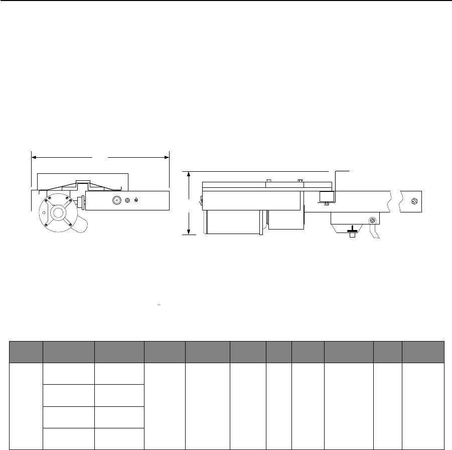
1601 Barrier Gate Operator
Magnetic Limits
Page Rev 1/2/19
39.50
15.25 14.75
387.35 mm 374.65 mm
1003.30 mm
9 ft
(2.75 m)
10 ft
(3.00 m)
12 ft
(3.65 m)
14 ft
(4.26 m)
1601-08x / 1601-18x1620-08x
1601
• Magnetic Limits
• Plug-in Loop Detector Ports
• Gate Tracker Data Output
• Up input memory buffer
• Down memory buffer
• Built-in power and operate switches
• Two convenience outlets
• Left or right hand mount
• Galvanized steel housing
• 90° in approximately 1.5 sec.
Model1
Mount
Options
Class of
Operation2
Voltage3
HP
Power
Outlets
Cycles /
Day
Loop
Ports4
Arm Type5
Maximum
Length
Fold
Option6
Breakaway
Option
Lighted
Option5
1601 Left or
Right II, III, IV
115 208
230 460
575 VAC
1/2 2 Continuous 2
Aluminum 14 Ft.
4.27 m Yes Yes Yes
Wood 14 Ft.
4.27 m Yes No No
Plastic 12 Ft.
3.66 m Yes No No
1. 1601 is available with white housing (1601-08x) or gray housing (1601-18x). Gray housing includes stainless steel door.
2. II = Commercial; III = Limited Access; IV = Restricted Access.
3. High voltage kit (P/N 2600-266) required for 208 Volt and higher.
4. Plug-in loop detector ports; up loop and down loop. DoorKing plug-in loop detectors only.
5. Always use lighted aluminum arm when using the lane barrier (1620-08x) add-on option.
6. Maximum arm length using the fold option is 12 Ft. (3.66 m).

January 2019 PRICE SCHEDULE A 2.0
Vehicular Traffic Control
Specifications subject to change without notice. Page 9
1601 Barrier Gate Operator
Magnetic Limits
Choose an Operator
1601-080 1/2 HP White Housing ................................ 3322.00
1601-081 1/2 HP w/COO1 White Housing .................. 4312.00
1601-180 1/2 HP Gray Housing .................................. 3690.00
1601-181 1/2 HP w/COO1 Gray Housing ..................... 4432.00
1. Convenience Open Option provides a method to raise the arm when
AC power has failed.
High Voltage
2600-266 High Voltage Kit............................................ 640.00
Allows the operator to be powered from 208, 230, 460 or 575 VAC
source voltage.
Choose Entrapment Protection (required) Devices
Use Type B1 (non‐contact) and/or Type B2 (contact) entrapment
protection devices to protect all areas where the risk of entrapment
exist ‐ see pages 42‐43.
Loops and Loop Detectors
See page 42 for a complete list of all loop detectors, prefabricated
loops and loop accessories available.
Surge Suppression
1879-080 High Voltage (120 VAC) ................................ 156.00
Backup Power Inverters
1000-083 1000 Watt, Pure Sine Wave ....................... 2148.00
1000-045 Inverter Post Mount Kit................................ 270.00
Includes two (2) 35 AH SLA batteries and can power up to two ½ HP
operators or one (1) 1 HP operator. This version is suitable to be used
with all brands of gate operators. See page 46 for more information.
Accessories
1601-281 Arm Hub Cover White1 ................................... 95.42
1601-283 Arm Hub Cover Gray1 ..................................... 95.42
1603-210 Traffic Signal & Mount Kit .......................... 1096.00
1601-092 Heater Kit2 .................................................... 270.00
1601-093 Fan Kit3 ......................................................... 270.00
1601-270 Manual Crank Kit .......................................... 278.00
1. Arm hub cover is included with the 1601 operator. Shown here for
replacement purposes only.
2. Use if temperature routinely falls below 10°F (‐12°C).
3. Use in hot, humid environments.
Aluminum Arm – Standard
1601-242 Hardware Kit - Required ............................... 172.00
Choose one arm from below
1601-516 Arm 14 Ft (4.27 m) ....................................... 324.00
1601-524 Arm 14 Ft (4.27 m), 2-Piece1......................... 392.00
1601-610 Arm Folding 12 Ft (3.66 m) ........................... 532.00
1. Ships in 7‐ft (2.13 m) long box to reduce shipping cost.
Aluminum Arm – LED Lighted
1601-242 Hardware Kit - Required ............................... 172.00
1601-535 Power Harness – Required ........................... 164.00
Choose one arm from below
1601-518 Arm 14 Ft (4.27 m) Lighted ........................... 580.00
1601-600 Arm Folding Lighted 12 Ft (3.66 m) ............ 1004.00
Aluminum Arm – Breakaway
1601-285 Breakaway Hardware Kit - Required............. 934.00
Choose one arm from below
1601-522 Arm 14 Ft (4.27 m) ....................................... 328.00
1601-528 Arm 14 Ft (4.27 m), 2-Piece1......................... 430.00
1601-520 Arm 14 Ft (4.27 m) Lighted ........................... 580.00
1. Ships in 7‐ft (2.13 m) long box to reduce shipping cost.
Wood Arm
1601-240 Hardware Kit - Required ............................... 144.00
Choose one arm from below
1601-348 Arm 14 Ft (4.27 m) ....................................... 256.00
1601-384 Arm Folding 12 Ft (3.66 m) ........................... 442.00
Plastic Arm
1601-241 Hardware Kit - Required ............................... 144.00
Choose one arm from below
1601-571 Arm 12 Ft (3.66 m) ....................................... 150.00
1601-383 Arm Folding 12 Ft (3.66 m) ........................... 442.00
Lane Barrier Add-On1
1620-080 9 ft (2.75 m) opening width ..................... 27,052.00
1620-081 10 ft (3.00 m) opening width ................... 27,682.00
1620-083 12 ft (3.65 m) opening width ................... 29,258.00
1620-085 14 ft (4.26 m) opening width ................... 29,992.00
1. Requires 1601 operator, 1601‐242 hardware kit, 1601‐535 power
harness and 1601‐518 arm – not included in the lane barrier pricing.
For passenger cars and light trucks only.
Page Rev 1/2/19
PRICE SCHEDULE A 2.0
Vehicular Traffic Control January 2019
Page 10 Specifications subject to change without notice.
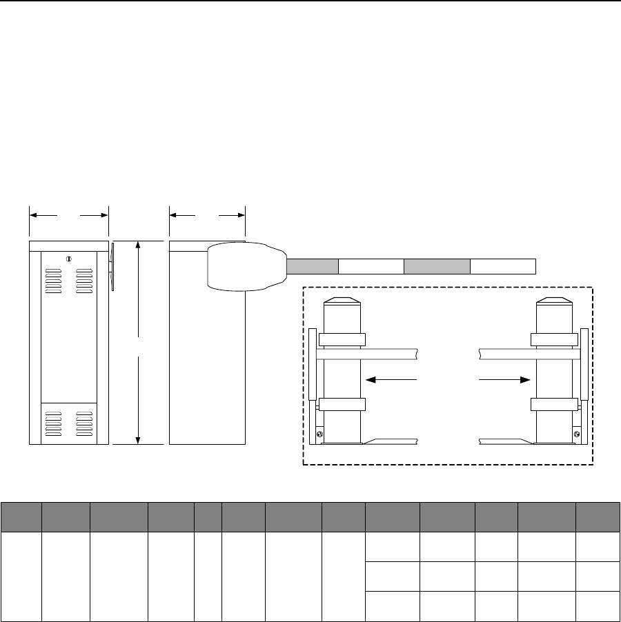
1602 Barrier Gate Operator
Magnetic Limits
Page Rev 1/2/19
15.75
39.50
15.25
34.50
876.30 mm
1003.30 mm
387.35 mm 400.05 mm
1602
• Magnetic Limits
• Plug-in Loop Detector Ports
• Gate Tracker Data Output
• Up input memory buffer
• Down memory buffer
• Built-in power and operate switches
• Two convenience outlets
• Left or right hand mount
• Galvanized steel housing
• 90° in approximately 5.5 sec.
Model
Mount
Options
Class of
Operation1
Voltage2
HP
Power
Outlets
Cycles /
Day
Loop
Ports3
Arm Type
Maximum
Length
Fold
Option
Breakaway
Option
Lighted
Option
1602 Left or
Right II, III, IV
115 208
230 460
575 VAC
1 2 Continuous 2
Aluminum
20 Ft.
6.09 m No No Yes
24 Ft.
7.31 m No No Yes
27 Ft.
8.23 m No No Yes
Wood 20 Ft.
6.09 m No No No
1. II = Commercial; III = Limited Access; IV = Restricted Access.
2. High voltage kit (P/N 2600-266) required for 208 Volt and higher.
3. Plug-in loop detector ports; up loop and down loop. DoorKing plug-in loop detectors only.

January 2019 PRICE SCHEDULE A 2.0
Vehicular Traffic Control
Specifications subject to change without notice. Page 11
1602 Barrier Gate Operator
Magnetic Limits
Choose an Operator
1602-090 1 HP............................................................ 4912.00
1602-091 1 HP w/COO1 .............................................. 5902.00
1. Convenience Open Option provides a method to raise the arm when
AC power has failed.
High Voltage
2600-266 High Voltage Kit ........................................... 640.00
Allows the operator to be powered from 208, 230, 460 or 575 VAC
source voltage.
Choose Entrapment Protection (required) Devices
Use Type B1 (non‐contact) and/or Type B2 (contact) entrapment
protection devices. See pages 40‐41 for a complete list of all
entrapment protection devices available.
Loops and Loop Detectors
Use Type B1 (non‐contact) and/or Type B2 (contact) entrapment
protection devices to protect all areas where the risk of entrapment
exist ‐ see pages 42‐43.
Surge Suppression
1879-080 High Voltage (120 VAC) ................................ 156.00
Backup Power Inverters
1000-083 1000 Watt, Pure Sine Wave ....................... 2148.00
1000-045 Inverter Post Mount Kit ............................... 270.00
Includes two (2) 35 AH SLA batteries and can power up to two ½ HP
operators or one (1) 1 HP operator. This version is suitable to be used
with all brands of gate operators. See page 46 for more information.
Accessories
1603-210 Traffic Signal & Mount Kit .......................... 1096.00
1601-092 Heater Kit1 .................................................... 270.00
1601-093 Fan Kit2 ......................................................... 270.00
1602-170 Manual Crank Kit.......................................... 470.00
1. Use if temperature routinely falls below 10°F (‐12°C).
2. Use in hot, humid environments.
Aluminum Arms
1602-162 3-Piece, 20 Ft (6.09 m) ............................... 3604.00
1602-164 3-Piece, 24 Ft (7.31 m) ............................... 3768.00
1602-166 3-Piece, 27 Ft (8.23 m) ............................... 3876.00
Aluminum Arms – LED Lighted
1602-172 3-Piece, 20 Ft (6.09 m) ............................... 3952.00
1602-174 3-Piece, 24 Ft (7.31 m) ............................... 4188.00
1602-176 3-Piece, 27 Ft (8.23 m) ............................... 4350.00
Wood Arm
1602-340 3-Piece, 20 Ft (6.09 m) ................................. 554.00
1602-041 Hardware Kit - Required ............................. 1012.00
Page Rev 1/2/19
PRICE SCHEDULE A 2.0
Vehicular Traffic Control January 2019
Page 12 Specifications subject to change without notice.
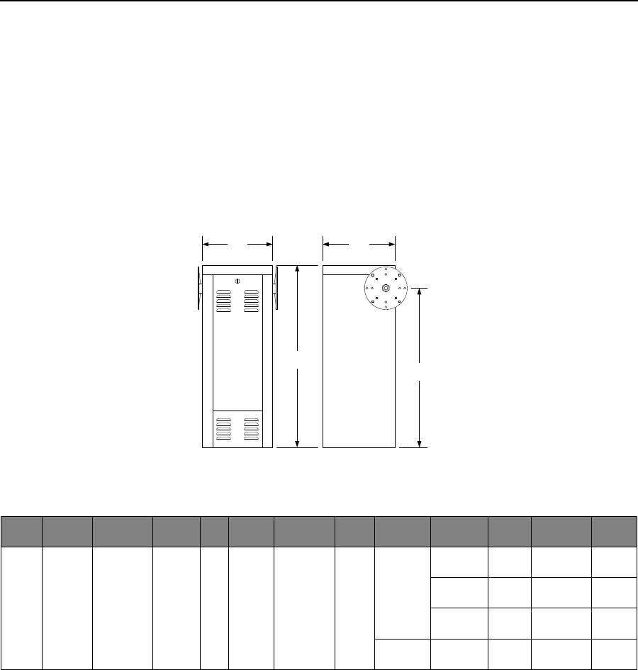
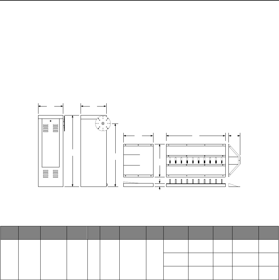
1603 Barrier Gate / Auto-Spikes
Magnetic Limits
Page Rev 1/2/19
43.50
15.25 15.50
38.50
2.00
20.00
18.00 36.00 7.00
387.35 mm 393.70 mm
1104.90 mm
977.90 mm
457.20 mm 914.40 mm 177.80 mm
508.00 mm
50.80 mm
1603
• Magnetic Limits
• Plug-in Loop Detector Ports
• Gate Tracker Data Output
• Up input memory buffer
• Down memory buffer
• Built-in power and operate switches
• Two convenience outlets
• Left or right hand mount
• Galvanized steel housing
• 90° in approximately 1.5 sec.
Model
Mount
Options
Class of
Operation1
Voltage2
HP
Power
Outlets
Cycles /
Day
Loop
Ports3
Arm Type
Maximum
Length
Fold
Option4
Breakaway
Option
Lighted
Option
1603 Left or
Right II, III, IV
115 208
230 460
575 VAC
1/2 2 Continuous 2
Aluminum 14 Ft.
4.27 m Yes Yes Yes
Wood 14 Ft.
4.27 m Yes No No
Plastic 12 Ft.
3.66 m Yes No No
1. II = Commercial; III = Limited Access; IV = Restricted Access.
2. High voltage kit (P/N 2600-266) required for 208 Volt and higher.
3. Plug-in loop detector ports; up loop and down loop. DoorKing plug-in loop detectors only.
4. Maximum arm length using the fold option is 12 Ft. (3.66 m).

January 2019 PRICE SCHEDULE A 2.0
Vehicular Traffic Control
Specifications subject to change without notice. Page 13
1603 Barrier Gate / Auto-Spikes
Magnetic Limits
Choose an Operator
1603-180 1/2 HP ........................................................ 4756.00
1603-181 1/2 HP w/COO1 .......................................... 5742.00
1. Convenience Open Option provides a method to raise the arm when
AC power has failed.
High Voltage
2600-266 High Voltage Kit ........................................... 640.00
Allows the operator to be powered from 208, 230, 460 or 575 VAC
source voltage.
Choose Entrapment Protection (required) Devices
Use Type B1 (non‐contact) and/or Type B2 (contact) entrapment
protection devices to protect all areas where the risk of entrapment
exist ‐ see pages 42‐43.
Loops and Loop Detectors
See page 42 for a complete list of all loop detectors, prefabricated
loops and loop accessories available.
Warning Sign - Required
1615-081 Auto-Spike Warning Sign............................ 1166.00
Illuminated warning sign MUST be used with the auto‐spike system.
Warning sign mounts on a 3.5 in (89 mm) post.
Traffic Signal - Recommended
1603-210 .................................................................... 1096.00
Surge Suppression
1879-080 High Voltage (120 VAC) ................................ 156.00
Backup Power Inverters
1000-083 1000 Watt, Pure Sine Wave ....................... 2148.00
1000-045 Inverter Post Mount Kit ............................... 270.00
Includes two (2) 35 AH SLA batteries and can power up to two ½ HP
operators or one (1) 1 HP operator. This version is suitable to be used
with all brands of gate operators. See page 46 for more information.
Aluminum Arm – Standard
1601-242 Hardware Kit - Required ............................... 172.00
Choose one arm from below
1601-516 Arm 14 Ft (4.27 m) ....................................... 324.00
1601-524 Arm 14 Ft (4.27 m), 2-Piece1......................... 392.00
1601-610 Arm Folding 12 Ft (3.66 m) ........................... 532.00
1. Ships in 7‐ft (2.13 m) long box to reduce shipping cost.
Aluminum Arm – LED Lighted
1601-242 Hardware Kit - Required ............................... 172.00
1601-535 Power Harness – Required ........................... 164.00
Choose one arm from below
1601-518 Arm 14 Ft (4.27 m) Lighted ........................... 580.00
1601-600 Arm Folding Lighted 12 Ft (3.66 m) ............ 1004.00
Spike Components
1603-168 Drive Ext 18 in (457 mm) - Required .......... 1134.00
Choose spike components from below
1603-165 Spike Section 3 Ft (0.91 m) ......................... 2022.00
1603-170 Tunnel Extension 18 in (457 mm) ............... 1134.00
1610-240 End Cap ........................................................ 446.00
Accessories
1601-281 Arm Hub Cover1 .............................................. 95.42
1615-081 Warning Sign2 ............................................. 1166.00
1603-210 Traffic Signal & Mount Kit .......................... 1096.00
1601-092 Heater Kit3 .................................................... 270.00
1601-093 Fan Kit4 ......................................................... 270.00
1601-270 Manual Crank Kit .......................................... 278.00
1. Arm hub cover is included with the 1603 operator. Shown here for
replacement purposes only.
2. Warning sign advises drivers that a one‐way lane condition exist and
must be installed with the auto‐spike system.
3. Use if temperature routinely falls below 10°F (‐12°C).
4. Use in hot, humid environments.
Page Rev 1/2/19
PRICE SCHEDULE A 2.0
Vehicular Traffic Control January 2019
Page 14 Specifications subject to change without notice.
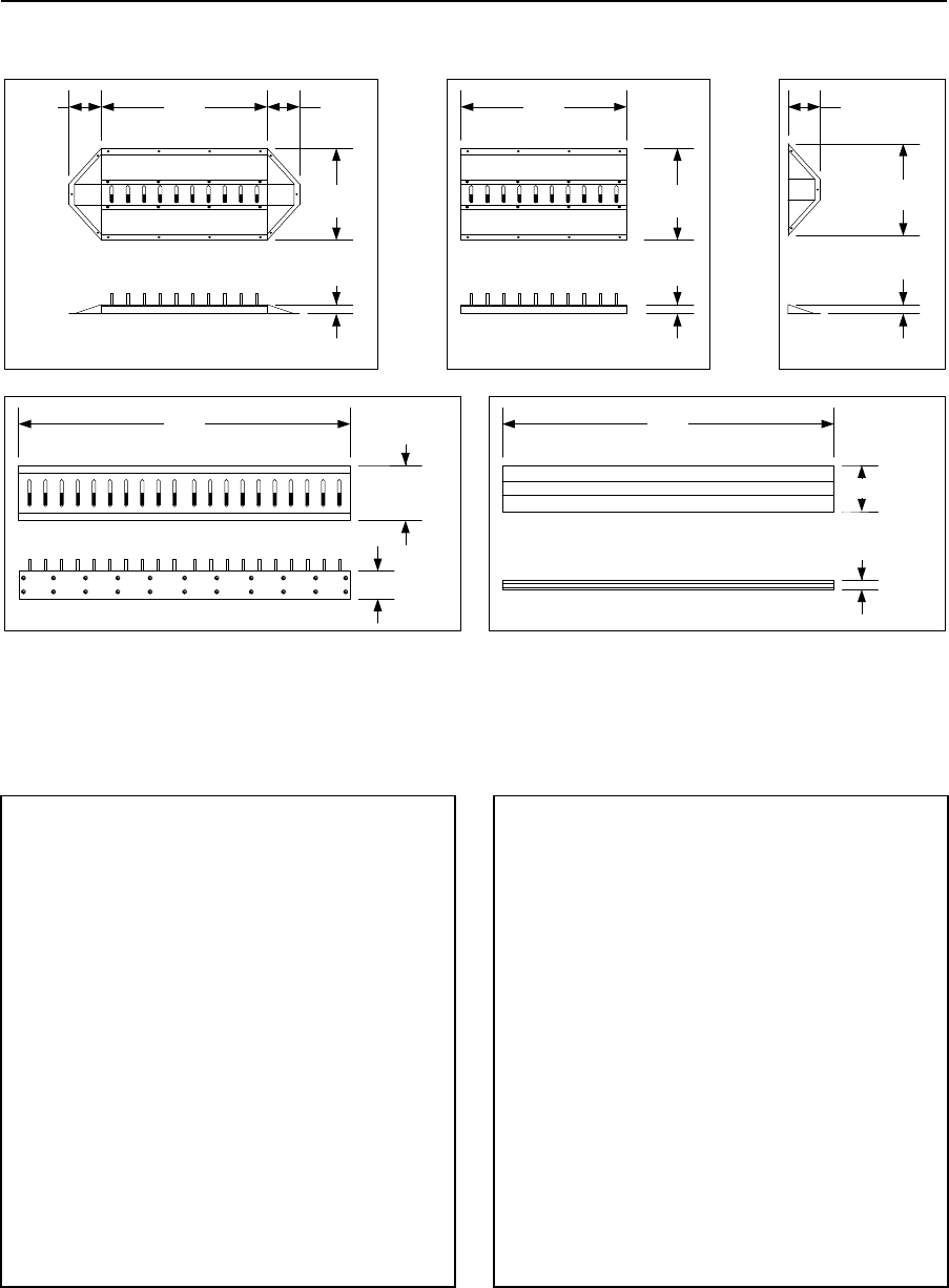
Model 1610
Stand-Alone Traffic Control Spikes
20.00
2.00
36.00 7.00
SURFACE MOUNT SPIKE ASSEMBLY
7.00
177.8 mm 177.8 mm
914.4 mm
508.0 mm
50.8 mm
SPIKE EXTENSION
36.00
20.00
2.00
914.4 mm
508.0 mm
50.8 mm
END CAP
7.00
20.00
2.00
50.8 mm
508.0 mm
177.8 mm
6.00
FLUSH MOUNT SPIKES
72.00
1.83 m
152.4 mm
12.00
304.8 mm
2.00
10.00
72.00
SPEED BUMP
1.83 m
50.8 mm
254 mm
Surface Mount Spikes
1610-088 Assembly .................................................... 3252.00
1610-087 Extension .................................................... 2290.00
1610-240 End Cap ......................................................... 446.00
1610-010 Lock Down Tool ............................................ 170.00
• Surface mount spikes use spring retraction and have a
lock down feature (requires 1610-010).
• 1610-088 assembly includes one (1) 1610-087 and two
(2) 1610-240.
Speed Bump
1610-150 Speed Bump ................................................. 390.00
Warning Sign - Required
1615-080 Warning Sign .............................................. 1166.00
• Warning signs are mandatory when spike systems are
installed. See next page for more options.
Flush Mount Spikes
1610-080 Spring Retraction ........................................1626.00
1610-090 Spring Retraction HD1 .................................1926.00
1610-081 Weighted Retraction...................................1626.00
1610-091 Weighted Retraction HD1 ............................1926.00
Flush Mount Spikes with Lock-Down Feature
1610-082 Spring Retraction2 .......................................1896.00
1610-092 Spring Retraction HD1, 2 ...............................2196.00
1610-083 Weighted Retraction3 .................................1896.00
1610-093 Weighted Retraction HD1, 3 .........................2196.00
1. HD = Heavy-duty, ¼ in (6 mm) top plate.
2. Includes 1610-012 lock-down tool.
3. Includes 1610-013 lock-down tool
Replacement Lock-Down Tools
1610-012 Use with Spring Retraction spikes ...................84.28
1610-013 Use with Weighted Retraction spikes ...........138.00
Page Rev 1/2/19
January 2019 PRICE SCHEDULE A 2.0
Vehicular Traffic Control
Specifications subject to change without notice. Page 15
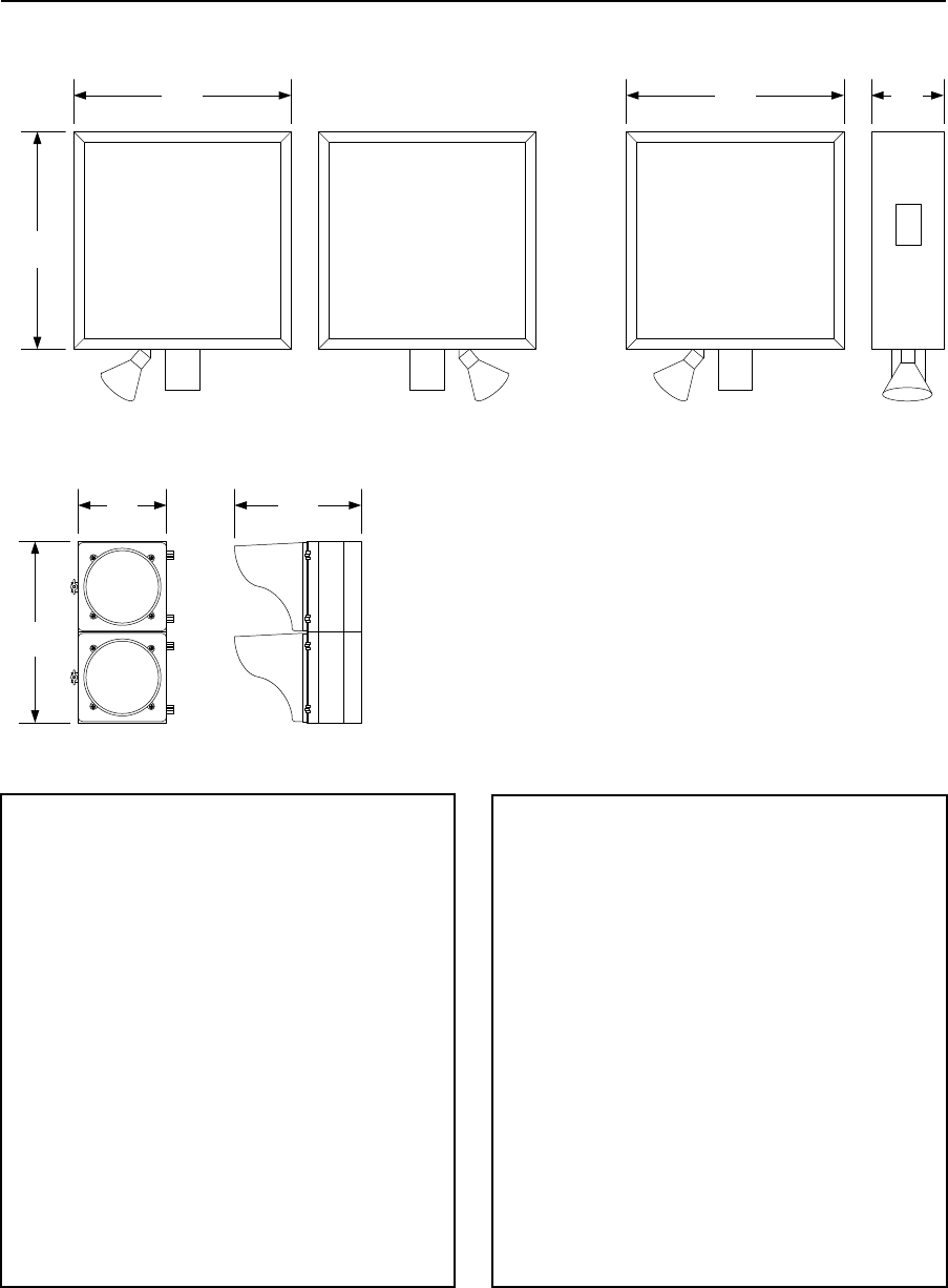
Traffic Control
Warning Sign, Traffic Signal
20.00
RED
GREEN
24.00
STOP
WRONG WAY
SEVERE TIRE
DAMAGE
5 MPH
MAXIMUM
Exceeding 5 MPH Will Result
In Severe Tire Damage!
NO:
Pedestrians, Bicycles or
Motorcycles
.
NO:
Pedestrians, Bicycles or
Motorcycles.
1615-080 Red Side 1615-080 Green Side
24.00
1615-081 Red Both Sides
8.00
9.75 14.00
24.00
NO:
Pedestrians, Bicycles or
Motorcycles.
STOP
PROCEED ONLY WHEN
SPIKES ARE DOWN
Proceeding Before Spikes Are Down
Will Result In Severe Tire Damage
!
609.6 mm
609.6 mm
609.6 mm 203.2 mm
247
.6 mm 355.6 mm
508 mm
1603-208
Traffic Signal
1603-208 ...................................................................... 932.00
1603-2101 ................................................................... 1096.00
1. Same as 1603-208 with mounting post kit for the 1603 auto-spike system.
Replacement Components
1603-550 LED Bulb, 10W, 1300 Lumens ......................... 27.52
Illuminated Warning Signs
1615-080 .................................................................... 1166.00
1615-082 (Spanish) .................................................... 1166.00
• Use these signs with surface and flush mount spike
systems. Signs mount on a 3.5 in (89 mm) post.
Illuminated Auto-Spike Warning Sign
1615-081 .................................................................... 1166.00
• Use this sign with the 1603 auto-spike system. Sign
mounts on a 3.5 in (89 mm) post.
Replacement Components
1615-022 LED T8 Tube, 12W, 700 Lumens ..................... 73.08
1615-023 LED Flood Lamp, 9W, 655 Lumens ............... 128.00
1615-032 RED panel..................................................... 144.00
1615-034 GREEN panel ................................................ 144.00
1615-035 RED Auto-spike panel .................................. 144.00
Page Rev 1/2/19

PRICE SCHEDULE A 2.0
Vehicular Traffic Control January 2019
Page 16 Specifications subject to change without notice.
Overhead / Barrier Operator Parts & Replacement Items
Miscellaneous Parts & Accessories
Circuit Boards
1601-010 ...................................................................... 638.00
Used in models 1601, 1602 and 1603
4405-018 ...................................................................... 638.00
Used in model 1175
1473-121 Convenience Open kit ................................... 348.00
Used in pre-2016 models 1150, 1601, 1602 and 1603
Barrier Operator Replacement Parts
1601-281 ........................................................................ 95.42
Barrier arm hub cover - white
1601-283 ........................................................................ 95.42
Barrier arm hub cover - gray
2599-101 ........................................................................ 21.34
Replacement Warning Sign
1601-069 ........................................................................ 42.14
Wood arm mounting bracket
1601-068 ........................................................................ 62.24
Plastic arm mounting bracket
1601-202 ........................................................................ 74.98
Aluminum arm mounting bracket
1601-079 ...................................................................... 144.00
Arm mounting hub
1801-009 ........................................................................ 91.52
12 Volt, 3 AH replacement battery
Warning Sign Replacement Components
1615-032 ...................................................................... 144.00
Warning sign replacement panel – RED
(use with 1610-080 warning sign)
1615-034 ...................................................................... 144.00
Warning sign replacement panel – GREEN
(use with 1610-080 warning sign)
1615-035 ...................................................................... 144.00
Auto-spike warning sign replacement panel
(use with 1610-081 warning sign)
1615-038 ...................................................................... 144.00
Warning Sign panel – Entrapment Alert
1615-022 ........................................................................ 73.08
T8 LED Tube Lamp, 12 Watt, 700 Lumens
(warning sign replacement bulbs)
1615-023 ...................................................................... 128.00
LED Flood Lamp, 9 Watt, 655 Lumens
1603-550 ........................................................................ 27.52
LED Bulb 10W, 1300 Lumens
(traffic signal replacement bulb)
Replacement Barrier Arms Yellow/Black Marking
(These arms ARE NOT MUTCD compliant)
1601-048 Wood Arm 14 Ft (4.27 m) ............................. 218.00
1601-084 Folding Wood Arm ........................................ 412.00
1601-271 Plastic Arm 12 Ft (3.66 m)............................. 122.00
1601-083 Folding Plastic Arm ....................................... 412.00
1601-216 Aluminum Arm 14 Ft (4.27 m) ...................... 288.00
1601-310 Folding Aluminum Arm ................................. 506.00
1602-040 3-Piece, 20 Ft (6.09 m) wood ........................ 452.00
1602-041 Hardware Kit for 1602-040 ......................... 1012.00
Spike System Replacement Components
1610-031 ........................................................................ 12.04
Replacement spring for 1610-080 spike set
1610-030 ........................................................................ 31.30
Replacement spike for 1610-080 spike set
1610-035 ........................................................................ 31.30
Replacement spike for 1610-083 spike set
1610-037 ........................................................................ 31.30
Spike spring lockdown assembly
1610-045 ........................................................................ 30.34
Spike, weighted assembly
Page Rev 1/2/19
January 2019 PRICE SCHEDULE A 2.0
Vehicular Traffic Control
Specifications subject to change without notice. Page 17
Blank Page
Page Rev 1/2/19
PRICE SCHEDULE A 2.0
Vehicular Traffic Control January 2019
Page 18 Specifications subject to change without notice.
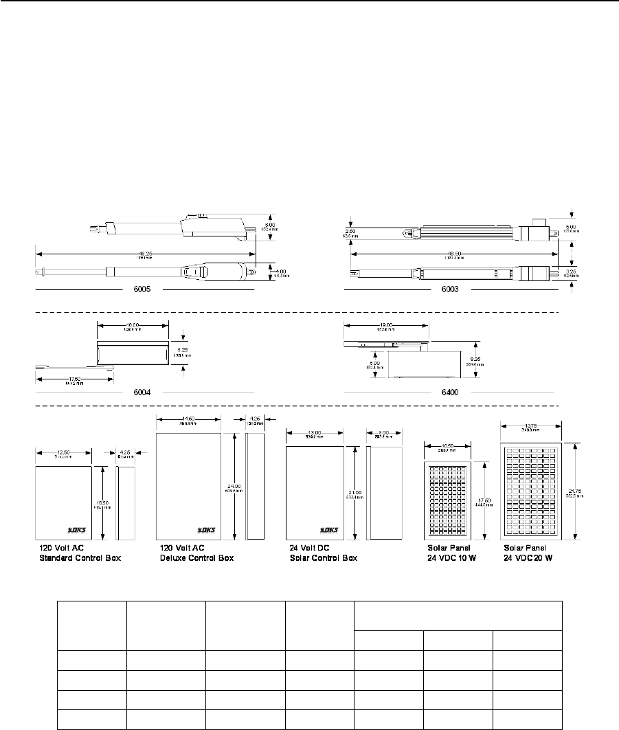
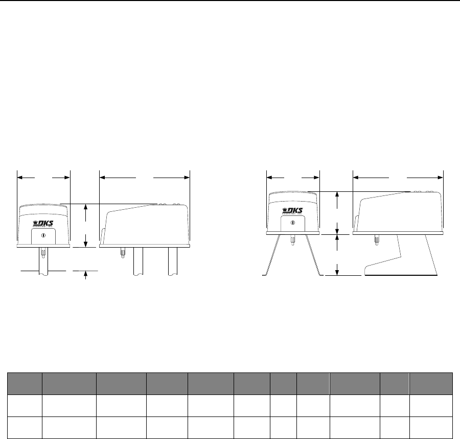
6005, 6003, 6004, 6400 Operators
Residential
Control Box
• 115 VAC or 24 VDC / Solar input power
• Includes batteries
• Single and Dual (bi-parting) gate operation
• 18 Ah or 35 Ah battery options
Operators
• 24 VDC continuous duty motor
• Built-in magnetic limit switches
• Slow-Start / Slow-Stop
• Small, compact designs
Model Max Gate
Weight1
Max Gate
Length1
Max Cycles
per Day2
Maximum Cycles on Backup Power2
3.5 Ah 18 Ah 35 Ah
6005 500 lbs. (227 kg) 14 ft. (4.26 m) 100 100 600 1200
6003 300 lbs. (136 kg) 10 ft. (3.05m) 100 100 600 1200
6004 500 lbs. (227 kg) 8 ft. (2.44 m) 100 100 600 1200
6400 300 lbs. (136 kg) 8 ft. (2.44 m) 100 100 600 1200
1. Assumes gate to be in good condition and swinging in a level plane.
2. Cycles shown are for single operators when solar panel(s) are not providing a charge to the batteries. Actual number of cycles will vary depending
on usage, accessories connected, gate weight, operating condition of gate, temperature, geographic location, weather (cloud coverage) and
charge state of the batteries.
Page Rev 1/2/19

January 2019 PRICE SCHEDULE A 2.0
Vehicular Traffic Control
Specifications subject to change without notice. Page 19
6005, 6003, 6004, 6400 Operators
Residential
Actuators
6005-380 .................................................................... 1494.00
6003-380 .................................................................... 1086.00
Operators
6004-380 Column Mount ........................................... 1626.00
6400-380 In-Ground................................................... 1806.00
Entrapment Protection (required)
Use Type B1 (non‐contact) and/or Type B2 (contact) entrapment
protection devices to protect all areas where the risk of entrapment
exist ‐ see pages 42‐43.
Actuator/Operator will not run without entrapment protection
device(s) connected to the controller board.
Loops and Loop Detectors
See page 42 for a complete list of all loop detectors, prefabricated
loops and loop accessories available.
Flange Bearing Hinge
1200-009 3000 Lb. (1360 kg) Weight Capacity ............. 152.00
Includes mounting bracket and hardware, two required per gate (top,
bottom), designed for use with 2” (50.8 mm) gate frame.
Sealed Bearing Hinge
1200-019 2000 Lb. (907 kg) Weight Capacity ............... 152.00
1200-039 3000 Lb. (1360 kg) Weight Capacity ............. 180.00
Includes mounting bracket and hardware, two required per gate (top,
bottom), designed for use with round or square gate frames.
Torsion Rod Assembly
1203-084 ...................................................................... 348.00
2600-299 Additional Torsion Rods ............................... 122.00
Counter‐balances uphill swing gates, includes top bracket, bottom
bracket and one (1) torsion rod. Up to five (5) additional torsion rods
can be added.
115 VAC Control Box
4302-311 Standard ....................................................... 830.00
4302-312 Deluxe ........................................................ 1000.00
Both Include two (2) 3.5 Ah batteries
Deluxe control box includes three (3) 115 VAC convenient outlets
Solar Control Box
4302-313 (No batteries) ............................................. 1000.00
4302-314 (Two 18 Ah batteries) ................................. 1432.00
4302-315 (Two 35 Ah batteries) ................................. 1552.00
Solar Panels
2000-076 24-Volt, 20-Watt .......................................... 722.00
Use with 35 Ah batteries
2000-077 24-Volt, 10-Watt .......................................... 364.00
Use with 18 Ah batteries
2000-110 Solar Panel Mount Bracket ............................. 61.72
Batteries
1801-009 12-volt, 3.5 Ah ................................................ 91.52
1801-004 12-volt, 18 Ah ............................................... 218.00
1801-005 12-volt, 35 Ah ............................................... 278.00
Surge Suppression
1879-080 High Voltage (120 VAC) ................................ 156.00
Bi-Parting (Dual) Gate Connection Cable
2600-755 30-Ft. (9.1 m) ................................................ 218.00
2600-756 40-Ft. (12.2 m) .............................................. 288.00
2600-757 50-Ft. (15.2 m) .............................................. 364.00
2600-754 500-Ft. (152.4 m) ........................................ 2890.00
Page Rev 1/2/19
PRICE SCHEDULE A 2.0
Vehicular Traffic Control January 2019
Page 20 Specifications subject to change without notice.
6050 / 6100 Swing Gate Operators
Automatic Magnetic Limits
Page Rev 1/2/19
Post Mount Pad Mount
13.50 23.00
11.00
6.00 minimum
342.90 mm 584.20 mm
279.40 mm
152.40 mm
13.50
342.90 mm
23.00
584.20 mm
11.00
279.40 mm
10.50
266.70 mm
6050 / 6100
• Self-Adjusting Magnetic Limits
• Type A inherent reverse system
• Plug-in Loop Detector Ports
• Gate Tracker Data Output
• Built-in power and reset switches
• Tamper protect feature
• Polyurethane cover
• Galvanized steel frame
• Pad or Post mounted
• Opens gate 90° in approximately 12 sec.
• Magnetic lock output
• Overlap feature for bi-parting gates
Model
Maximum
Gate Weight
Maximum
Gate Length
Mount
Options1
Class of
Operation2
Voltage
HP
Power
Outlets
Maximum
Cycles / Day
Loop
Ports4
Adjustable
Clutch5
6050 400 Lbs
181 KG
10 Ft
3.05 m Pad / Post I 115 VAC 1/2 3 N/A 100 2 Yes
6100 500 Lbs
226 KG
14 Ft
4.26 m Pad / Post I, II 115 VAC 1/2 N/A Continuous 2 Yes
1. Select pad or post mount hardware kit when ordering.
2. I = Residential; II = Commercial.
3. This is an intermittent duty cycle motor.
4. Plug-in loop detector ports; open and reverse. DoorKing plug-in loop detectors only.
5. Clutch is not applicable as an entrapment protection device.

January 2019 PRICE SCHEDULE A 2.0
Vehicular Traffic Control
Specifications subject to change without notice. Page 21
6050 / 6100 Swing Gate Operators
Automatic Magnetic Limits
Page Rev 1/2/19
Step 1: Choose an Operator or Operator Set
6050-380 Primary ...................................................... 2554.00
6050-381 Secondary .................................................. 1890.00
Secondary operator includes 30 feet (9.1 m) of interconnection cable.
6100-380 Primary ...................................................... 2804.00
6100-381 Secondary .................................................. 2144.00
Secondary operator includes 40 feet (12.2 m) of interconnection cable.
Step 2: Choose a Mounting Kit (Includes Arms)
2600-671 Pad Mount Kit .............................................. 554.00
2600-674 Post Mount Kit ............................................. 458.00
Step 3: Choose Entrapment Protection (required) Devices
Use Type B1 (non‐contact) and/or Type B2 (contact) entrapment
protection devices to protect all areas where the risk of entrapment
exist ‐ see pages 42‐43.
Operator will not run without entrapment protection device(s)
connected to the controller board.
Loops and Loop Detectors
See page 42 for a complete list of all loop detectors, prefabricated
loops and loop accessories available.
Post Mount Base Plate
2600-664 ...................................................................... 212.00
Use to mount 6050 and 6100 operators onto an existing concrete pad.
Surge Suppression
1879-080 High Voltage (120 VAC) ................................ 156.00
Heater Kit
1601-154 120 VAC ....................................................... 484.00
Use if temperature routinely falls below 10°F (‐12°C).
Backup Power Inverters
1000-083 1000 Watt, Pure Sine Wave ....................... 2148.00
1000-045 Inverter Post Mount Kit ................................ 270.00
Includes two (2) 35 AH SLA batteries and can power up to two ½ HP
operators or one (1) 1 HP operator. This version is suitable to be used
with all brands of gate operators. See page 46 for more information.
Bi-Parting (Dual) Gate Interconnection Cable
2600-755 30-Ft. (9.1 m) ................................................ 218.00
2600-756 40-Ft. (12.2 m) .............................................. 288.00
2600-757 50-Ft. (15.2 m) .............................................. 364.00
2600-754 500-Ft. (152.4 m) ........................................ 2890.00
Flange Bearing Hinge
1200-009 3000 Lb. (1360 kg) Weight Capacity ............. 152.00
Includes mounting bracket and hardware, two required per gate (top,
bottom), designed for use with 2” (50.8 mm) gate frame.
Sealed Bearing Hinge
1200-019 2000 Lb. (907 kg) Weight Capacity ............... 152.00
1200-039 3000 Lb. (1360 kg) Weight Capacity ............. 180.00
Includes mounting bracket and hardware, two required per gate (top,
bottom), designed for use with round or square gate frames.
Uphill Arm Pivot Assembly
6500-490 ...................................................................... 240.00
Use with 1203‐084 Torsion Rod Assembly.
Torsion Rod Assembly
1203-084 ...................................................................... 348.00
2600-299 Additional Torsion Rods ............................... 122.00
Counter‐balances uphill swing gates, includes top bracket, bottom
bracket and one (1) torsion rod. Up to five (5) additional torsion rods
can be added.
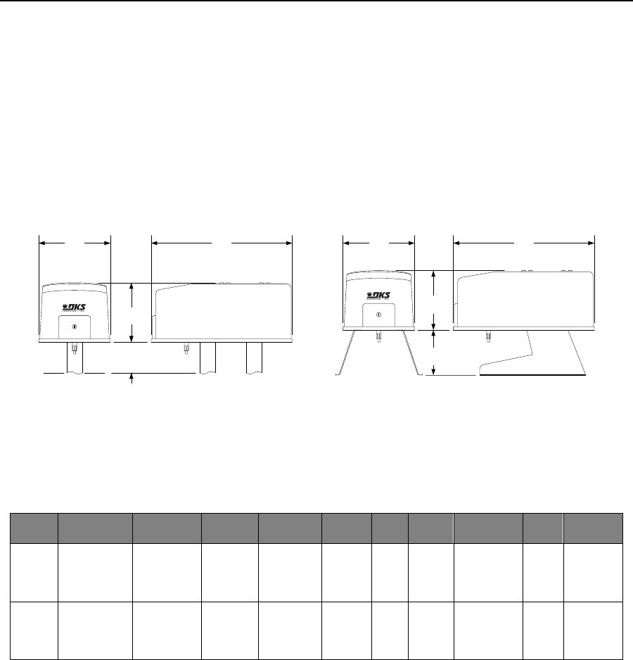
PRICE SCHEDULE A 2.0
Vehicular Traffic Control January 2019
Page 22 Specifications subject to change without notice.
6300 Swing Gate Operators
Automatic Magnetic Limits
6300
• Self-Adjusting Magnetic Limits
• Type A inherent reverse system
• Plug-in Loop Detector Ports
• Gate Tracker Data Output
• Built-in power and reset switches
• Tamper protect feature
• Polyurethane cover
• Galvanized steel frame
• Pad or Post mounted
• Opens gate 90° in approximately 16 sec.
• Magnetic lock output
• Overlap feature for bi-parting gates
Post Mount Pad Mount
16.25
412.75 mm
32.00
812.80 mm
13.50
342.90 mm
10.25
260.35 mm
16.25 32.00
412.75 mm 812.80 mm
13.50
342.90 mm
7.00 minimum
177.80 mm
Model
Maximum
Gate Weight
Maximum
Gate Length
Mount
Options1
Class of
Operation2
Voltage3
HP
Power
Outlets
Maximum
Cycles / Day
Loop
Ports3
Adjustable
Clutch4
6300 700 Lbs
317 KG
18 Ft
5.48 m Pad / Post I, II, III, IV
115 208
230 460
575 VAC
1/2 2 Continuous 2 Yes
6300 800 Lbs
362 KG
22 Ft
6.70 m Pad / Post I, II, III, IV
115 208
230 460
575 VAC
1 2 Continuous 2 Yes
1. Select pad or post mount hardware kit when ordering.
2. I = Residential; II = Commercial; III = Limited Access; IV = Restricted Access
3. High voltage kit (P/N 2600-266) required for 208 Volt and higher.
4. Plug-in loop detector ports; open and reverse. DoorKing plug-in loop detectors only.
5. Clutch is not applicable as an entrapment protection device.
Page Rev 1/2/19

January 2019 PRICE SCHEDULE A 2.0
Vehicular Traffic Control
Specifications subject to change without notice. Page 23
6300 Swing Gate Operators
Automatic Magnetic Limits
Step 1: Choose an Operator or Operator Set
6300-380 Primary ½ HP .............................................. 3130.00
6300-381 Secondary ½ HP ......................................... 2528.00
6300-384 Primary 1 HP .............................................. 3768.00
6300-385 Secondary 1 HP .......................................... 3108.00
Secondary operators includes 50 feet (15.2 m) of interconnection cable.
High Voltage Kit
2600-266 ...................................................................... 640.00
Allows the operator to be powered from 208, 230, 460 or 575 VAC
source voltage. In dual gate applications, only one (1) kit is required.
Step 2: Choose a Mounting Kit (Includes Arms)
2600-264 Pad Mount Kit .............................................. 712.00
2600-263 Post Mount Kit ............................................. 712.00
Step 3: Choose Entrapment Protection (required) Devices
Use Type B1 (non‐contact) and/or Type B2 (contact) entrapment
protection devices to protect all areas where the risk of entrapment
exist ‐ see pages 42‐43.
Operator will not run without entrapment protection device(s)
connected to the controller board.
Loops and Loop Detectors
See page 42 for a complete list of all loop detectors, prefabricated
loops and loop accessories available.
Surge Suppression
1879-080 High Voltage (120 VAC) ................................ 156.00
Heater Kit
1601-154 120 VAC........................................................ 484.00
1601-197 208 / 230 VAC ............................................ 1012.00
1601-198 460 VAC...................................................... 1012.00
Use if temperature routinely falls below 10°F (‐12°C).
Backup Power Inverters
1000-083 1000 Watt, Pure Sine Wave ....................... 2148.00
1000-045 Inverter Post Mount Kit ................................ 270.00
Includes two (2) 35 AH SLA batteries and can power up to two ½ HP
operators or one (1) 1 HP operator. This version is suitable to be used
with all brands of gate operators. See page 46 for more information.
Bi-Parting (Dual) Gate Interconnection Cable
2600-755 30-Ft. (9.1 m) ................................................ 218.00
2600-756 40-Ft. (12.2 m) .............................................. 288.00
2600-757 50-Ft. (15.2 m) .............................................. 364.00
2600-754 500-Ft. (152.4 m) ........................................ 2890.00
Flange Bearing Hinge
1200-009 3000 Lb. (1360 kg) Weight Capacity ............. 152.00
Includes mounting bracket and hardware, two required per gate (top,
bottom), designed for use with 2” (50.8 mm) gate frame.
Sealed Bearing Hinge
1200-019 2000 Lb. (907 kg) Weight Capacity ............... 152.00
1200-039 3000 Lb. (1360 kg) Weight Capacity ............. 180.00
Includes mounting bracket and hardware, two required per gate (top,
bottom), designed for use with round or square gate frames.
Uphill Arm Pivot Assembly
6500-490 ...................................................................... 240.00
Use with 1203‐084 Torsion Rod Assembly.
Torsion Rod Assembly
1203-084 ...................................................................... 348.00
2600-299 Additional Torsion Rods ............................... 122.00
Counter‐balances uphill swing gates, includes top bracket, bottom
bracket and one (1) torsion rod. Up to five (5) additional torsion rods
can be added.
Page Rev 1/2/19
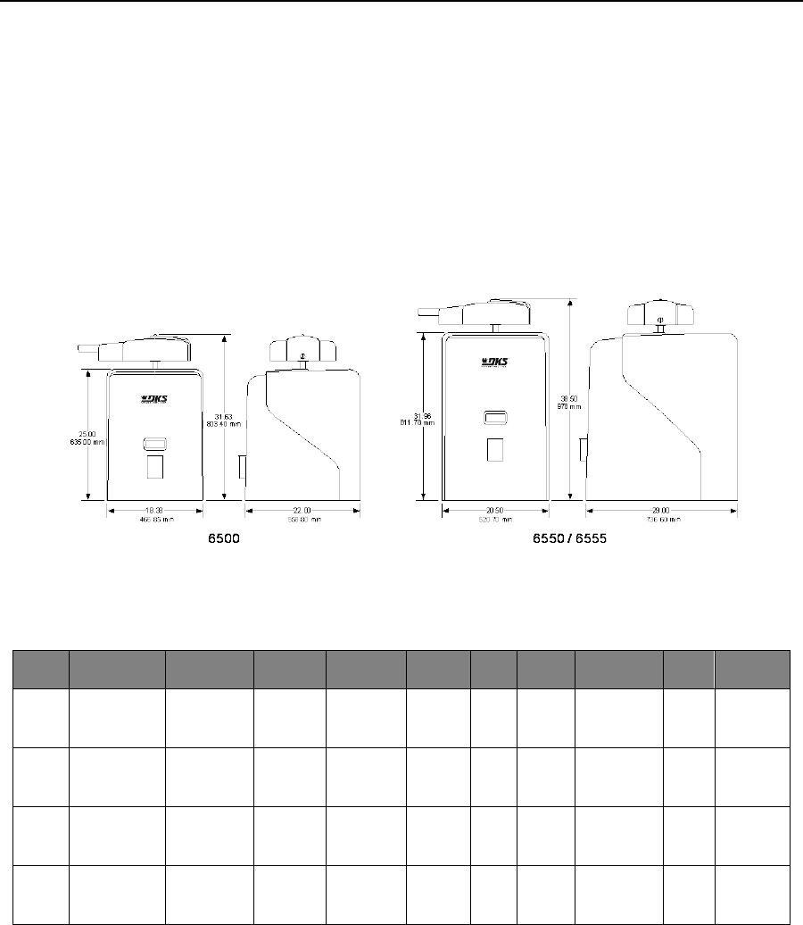
PRICE SCHEDULE A 2.0
Vehicular Traffic Control January 2019
Page 24 Specifications subject to change without notice.
6500 / 65505 / 65555 Swing Gate Operators
Adjustable Limit Swing Gate Operators
6500 / 65505 / 65555
• Adjustable Magnetic Limits
• Type A inherent reverse system
• Plug-in Loop Detector Ports
• Gate Tracker Data Output
• Built-in power and reset switches
• Polyurethane cover
• Galvanized steel frame
• Opens gate 90° in approximately 16 sec.
• Magnetic lock output
• Overlap feature for bi-parting gates
Model
Maximum
Gate Weight
Maximum
Gate Length
Mount
Class of
Operation1
Voltage
2
HP
Power
Outlets
Maximum
Cycles / Day
Loop
Ports2
Adjustable
Clutch
6500 700 Lbs
317 KG
18 Ft
5.48 m Pad I, II, III, IV
115 208
230 460
575 VAC
1/2 2 Continuous 2 No
6500 800 Lbs
362 KG
22 Ft
6.70 m Pad I, II, III, IV
115 208
230 460
575 VAC
1 2 Continuous 2 No
65505 2000 Lbs
907 KG
25 Ft
7.62 m Pad II, III, IV
115 208
230 460
575 VAC
1 2 Continuous 2 No
65554,5 2000 Lbs
907 KG
25 Ft
7.62 m Pad II, III, IV 230 VAC 1 2 Continuous 2 No
1. I = Residential; II = Commercial; III = Limited Access; IV = Restricted Access
2. High voltage kit (P/N 2600-266) required for 208 Volt and higher.
3. Plug-in loop detector ports; open and reverse. DoorKing plug-in loop detectors only.
4. This operator has a variable speed drive.
5. Models 6550 and 6555 are not listed to the UL 325 standard at this time.
Page Rev 1/2/19

January 2019 PRICE SCHEDULE A 2.0
Vehicular Traffic Control
Specifications subject to change without notice. Page 25
6500 / 6550 / 6555 Swing Gate Operators
Adjustable Limit Swing Gate Operators
Step 1: Choose an Operator or Operator Set
6500-380 Primary ½ HP.............................................. 3928.00
6500-381 Secondary ½ HP ......................................... 3252.00
Secondary operator includes 50 feet (15.2 m) of interconnection cable.
6500-384 Primary 1 HP .............................................. 4490.00
6500-385 Secondary 1 HP .......................................... 3928.00
Secondary operator includes 50 feet (15.2 m) of interconnection cable.
6550-380 Primary 1 HP .............................................. 6178.00
6550-384 Secondary 1 HP .......................................... 5538.00
Secondary operator includes 50 feet (15.2 m) of interconnection cable.
Model 6550 is not listed to UL 325 at this time.
6555-381 Primary 1 HP 230 VAC Variable Speed ....... 8830.00
Model 6555 is not listed to UL 325 at this time.
High Voltage Kit
2600-266 ...................................................................... 640.00
Allows the operator to be powered from 208, 230, 460 or 575 VAC
source voltage. In dual gate applications, only one (1) kit is required.
Not available on 6555‐081 operator.
Step 2: Choose Entrapment Protection (required) Devices
Use Type B1 (non‐contact) and/or Type B2 (contact) entrapment
protection devices to protect all areas where the risk of entrapment
exist ‐ see pages 42‐43.
Operator will not run without entrapment protection device(s)
connected to the controller board.
Loops and Loop Detectors
See page 42 for a complete list of all loop detectors, prefabricated
loops and loop accessories available.
Surge Suppression
1879-080 High Voltage (120 VAC) ................................ 156.00
Heater Kit
1601-154 120 VAC ....................................................... 484.00
1601-197 208 / 230 VAC ............................................ 1012.00
1601-198 460 VAC ..................................................... 1012.00
Use if temperature routinely falls below 10°F (‐12°C).
Backup Power Inverters
1000-083 1000 Watt, Pure Sine Wave ....................... 2148.00
1000-045 Inverter Post Mount Kit ................................ 270.00
Includes two (2) 35 AH SLA batteries and can power up to two ½ HP
operators or one (1) 1 HP operator. This version is suitable to be used
with all brands of gate operators. See page 46 for more information.
Bi-Parting (Dual) Gate Interconnection Cable
2600-755 30-Ft. (9.1 m) ................................................ 218.00
2600-756 40-Ft. (12.2 m) .............................................. 288.00
2600-757 50-Ft. (15.2 m) .............................................. 364.00
2600-754 500-Ft. (152.4 m) ........................................ 2890.00
Flange Bearing Hinge
1200-009 3000 Lb. (1360 kg) Weight Capacity ............. 152.00
Includes mounting bracket and hardware, two required per gate (top,
bottom), designed for use with 2” (50.8 mm) gate frame.
Sealed Bearing Hinge
1200-019 2000 Lb. (907 kg) Weight Capacity ............... 152.00
1200-039 3000 Lb. (1360 kg) Weight Capacity ............. 180.00
Includes mounting bracket and hardware, two required per gate (top,
bottom), designed for use with round or square gate frames.
Uphill Arm Pivot Assembly
6500-490 ...................................................................... 240.00
Use with 6500 operator and 1203‐084 Torsion Rod Assembly.
6550-490 ...................................................................... 240.00
Use with 6550 operator and 1203‐084 Torsion Rod Assembly.
Torsion Rod Assembly
1203-084 ...................................................................... 348.00
2600-299 Additional Torsion Rods ............................... 122.00
Counter‐balances uphill swing gates, includes top bracket, bottom
bracket and one (1) torsion rod. Up to five (5) additional torsion rods
can be added.
Page Rev 1/2/19
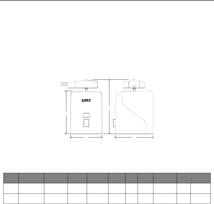
PRICE SCHEDULE A 2.0
Vehicular Traffic Control January 2019
Page 26 Specifications subject to change without notice.
6524 DC Swing Gate Operator
Adjustable Limit Swing Gate Operator
6524
• Input 115/230 VAC or 24 VDC (Solar)
• Adjustable Magnetic Limits
• Plug-in Loop Detector Ports
• Gate Tracker Data Output
• Built-in power and reset switches
• Built-in Battery Backup
• Galvanized steel frame
• Opens gate 90° in approximately 16 sec.
• Magnetic lock output
• Overlap feature for bi-parting gates
18.38
31.63
22.00
25.00
466.85 mm 558.80 mm
635.00 mm
803.40 mm
Model
Maximum
Gate Weight
Maximum
Gate Length
Mount
Class of
Operation1
Voltage
HP
Power
Outlets
Maximum
Cycles / Day
Loop
Ports2
Adjustable
Clutch
6524 800 Lbs
362 KG
16 Ft
4.88 m Pad I, II, III, IV 115/230
VAC 1/2 2 Continuous3,4 2 No
65245 800 Lbs
362 KG
16 Ft
4.88 m Pad I, II, III, IV 24 VDC
(Solar) 1/2 0 Up to 1504 2 No
1. I = Residential; II = Commercial; III = Limited Access; IV = Restricted Access
2. Plug-in loop detector ports; open and reverse. DoorKing plug-in loop detectors only.
3. Continuous operation is when AC power is present. Operation on battery backup (7.5 Ah batteries) is limited to approximately 40 cycles.
4. Up to 150 cycles with 18 Ah batteries. Actual number of cycles will vary depending on usage, accessories connected, gate weight, operating
condition of gate, temperature and charge state of the batteries. Charge state of batteries is affected by geographical location of the product
when using solar to recharge the batteries.
5. Solar powered operators will not support bi-parting (dual) gate operation.
Page Rev 1/2/19

January 2019 PRICE SCHEDULE A 2.0
Vehicular Traffic Control
Specifications subject to change without notice. Page 27
6524 DC Swing Gate Operators
Adjustable Limit Swing Gate Operator
Step 1: Choose an Operator
6524-380 115/230 VAC .............................................. 3508.00
Includes two 7.5 Ah batteries for limited backup operation. Order 18
Ah batteries to extend the backup operation cycles.
Includes 50 feet (15 m) of RS 485 interconnection cable for bi‐parting
(dual) gate operation.
6524-381 24 VDC (Solar) ............................................ 3298.00
24 VDC solar input power only (supply your own batteries and solar
charging system or use DKS solar kit).
Solar powered operators will not support bi‐parting (dual) gate
operation.
Step 2: Choose Entrapment Protection (required) Devices
Use Type B1 (non‐contact) and/or Type B2 (contact) entrapment
protection devices to protect all areas where the risk of entrapment
exist ‐ see pages 42‐43.
Operator will not run without entrapment protection device(s)
connected to the controller board.
Battery / Solar Options
1801-004 12-Volt, 18 Ah Battery1 ................................ 218.00
2000-077 24-Volt, 10 Watt Solar Panel ........................ 364.00
2000-070 Solar Kit2 ...................................................... 850.00
1. Two required for 24 Volt operation.
2. Kit includes two (2) 18 Ah batteries, 10 Watt solar panel and
bracket.
Loops and Loop Detectors
See page 42 for a complete list of all loop detectors, prefabricated
loops and loop accessories available.
Surge Suppression
1879-080 High Voltage (120 VAC) ................................ 156.00
Heater Kit
6500-480 120 VAC ....................................................... 554.00
1601-197 208 / 230 VAC ............................................ 1012.00
Use if temperature routinely falls below 10°F (‐12°C). Cannot be used
with solar powered operators.
Backup Power Inverters
1000-083 1000 Watt, Pure Sine Wave ....................... 2148.00
1000-045 Inverter Post Mount Kit ................................ 270.00
Includes two (2) 35 AH SLA batteries and can power up to two ½ HP
operators or one (1) 1 HP operator. This version is suitable to be used
with all brands of gate operators. See page 46 for more information.
Bi-Parting (Dual) Gate Interconnection Cable
2600-755 30-Ft. (9.1 m) ................................................ 218.00
2600-756 40-Ft. (12.2 m) .............................................. 288.00
2600-757 50-Ft. (15.2 m) .............................................. 364.00
2600-754 500-Ft. (152.4 m) ........................................ 2890.00
Flange Bearing Hinge
1200-009 3000 Lb. (1360 kg) Weight Capacity ............. 152.00
Includes mounting bracket and hardware, two required per gate (top,
bottom), designed for use with 2” (50.8 mm) gate frame.
Sealed Bearing Hinge
1200-019 2000 Lb. (907 kg) Weight Capacity ............... 152.00
1200-039 3000 Lb. (1360 kg) Weight Capacity ............. 180.00
Includes mounting bracket and hardware, two required per gate (top,
bottom), designed for use with round or square gate frames.
Uphill Arm Pivot Assembly
6500-490 ...................................................................... 240.00
Use with 1203‐084 Torsion Rod Assembly.
Torsion Rod Assembly
1203-084 ...................................................................... 348.00
2600-299 Additional Torsion Rods ............................... 122.00
Counter‐balances uphill swing gates, includes top bracket, bottom
bracket and one (1) torsion rod. Up to five (5) additional torsion rods
can be added.
Bi-Parting (Dual) Gate Interconnection Cable RS 485
9024-136 50-Ft. (15 m) ................................................... 42.00
9024-137 984-Ft. (300 m) ............................................. 662.00
Page Rev 1/2/19
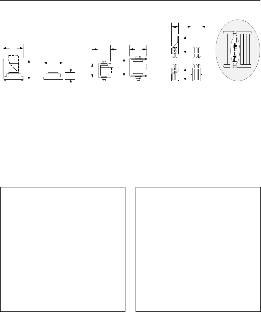
PRICE SCHEDULE A 2.0
Vehicular Traffic Control January 2019
Page 28 Specifications subject to change without notice.
Swing Gate Accessories
Hinges, Torsion Rod Counter-Balance
4.50
114 mm
4.50
114 mm
4.25
2-in
(51 mm)
Fr am e
2.75
95 mm
3.13
79 mm
3.75
1.50
108 mm
1200-009 1200-010
38 mm
4.00
38 mm
1200-019
101 mm
1200-039 1203-084
2.50
4.00
101 mm
1.50
2.88
73 mm
70 mm
63 mm
Flange Bearing Hinge
1200-009 3000 Lb. (1360 Kg) weight capacity .............. 152.00
1200-010 Replacement bearing ...................................... 91.74
• Designed for use with 2 inch (51 mm) gate frame.
• Includes mounting bracket and hardware.
• Zert grease fitting.
• Two required (top, bottom) per gate.
Sealed Bearing Hinge
1200-019 2000 Lb. (907 Kg) weight capacity ................ 152.00
1200-039 3000 Lb. (1360 Kg) weight capacity .............. 180.00
• Designed for use with round or square gate frame.
• Includes mounting bracket and hardware.
• Two required (top, bottom) per gate.
Torsion Rod Counter-Balance Assembly
1203-0841 Torsion Rod Assembly .................................348.00
2600-2992 Torsion Rods ................................................122.00
1. Includes one (1) 2600-299 torsion rod.
2. Up to five (5) additional rods can be added to the 1203-084 assembly.
Page Rev 1/2/19

January 2019 PRICE SCHEDULE A 2.0
Vehicular Traffic Control
Specifications subject to change without notice. Page 29
Swing Gate Operator Parts & Accessories
Miscellaneous Parts & Accessories
Page Rev 1/2/19
Circuit Boards
4100-018 ...................................................................... 542.00
Used in model 6524
4302-018 ...................................................................... 602.00
Used in models 6005, 6003, 6004 and 6400
4405-018 ...................................................................... 638.00
Used in model 6500, 6550
4502-018 ...................................................................... 638.00
Used in models 6050, 6100 and 6300
Base Plate, Mounting Pipes, Pivot Arm
2600-664 Concrete Base Plate ..................................... 180.00
Use to mount the 6050 or 6100 post mount operators onto
an existing concrete pad
6500-490 Uphill Arm Pivot Assembly ........................... 240.00
Use with 6050, 6100, 6300 and 6500 operators when the gate
opens on an uphill or downhill slope. Should be used with
1203-084 Torsion Rod Assembly.
6550-490 Uphill Arm Pivot Assembly ........................... 240.00
Use with 6550 operator when the gate opens on an uphill or
downhill slope. Should be used with 1203-084 Torsion Rod
Assembly.
Bi-Parting Connection Cable
2600-754 Primary / Secondary Cable ......................... 2890.00
500-ft (152.4 m) roll
Batteries
1801-009 Battery ........................................................... 91.52
12 Volt, 3.5 Amp Hour
1801-004 Battery ......................................................... 218.00
12 Volt, 18 Amp Hour
1801-005 Battery ......................................................... 278.00
12 Volt, 35 Amp Hour
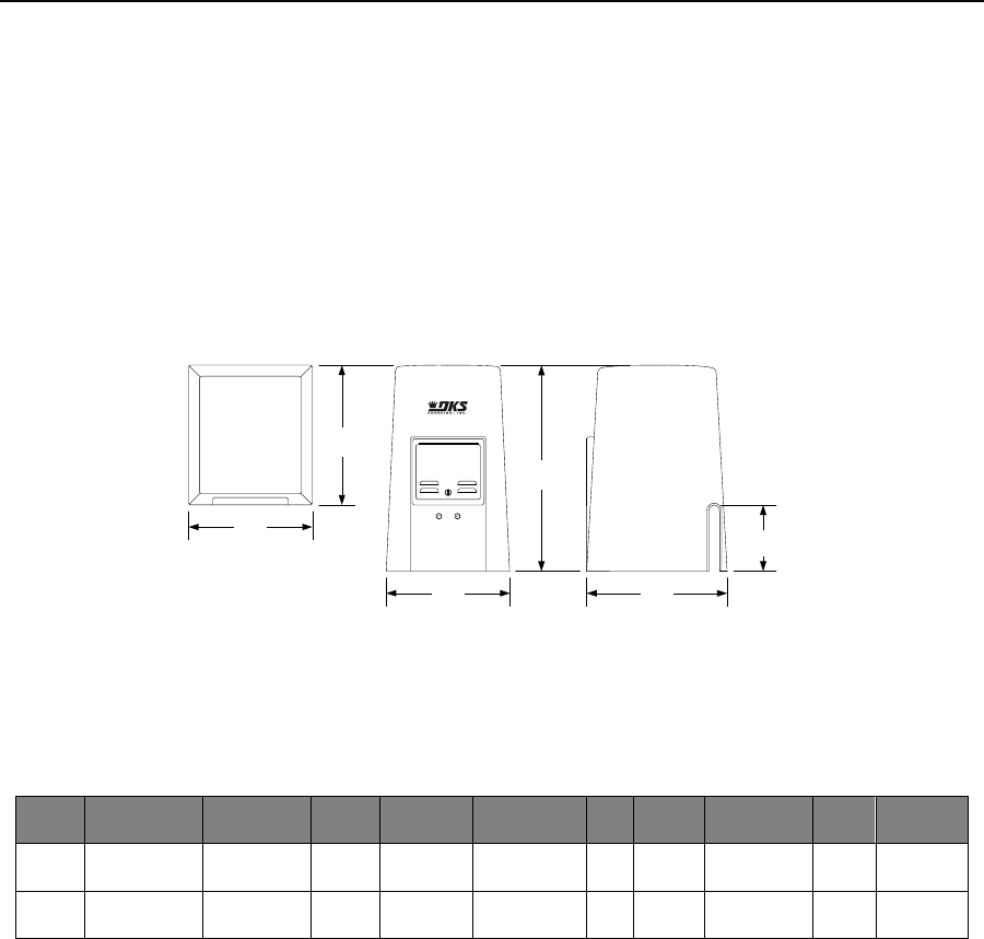
PRICE SCHEDULE A 2.0
Vehicular Traffic Control January 2019
Page 30 Specifications subject to change without notice.
9000 Slide Gate Operators
Adjustable Limit Slide Gate Operator
• 30:1 Gear Reducer Drive Train
• Steel frame
• Polyurethane cover
• 20-Feet (6 m) #40 Chain
• Gate tracker data output
9000
• Adjustable Limits
• Plug-in Loop Detector Ports
• Built-in power and reset switches
• Two 115 VAC convenience outlets
• Selectable stop/ reverse function
16.75
28.00
19.00
9.00
16.75
19.00
425.45 mm
425.45 mm
482.60 mm
482.60 mm
711.20 mm
228.60 mm
Model
Maximum
Gate Weight
Maximum
Gate Length
Mount
Class of
Operation1
Voltage2
HP
Power
Outlets
Maximum
Cycles / Day
Loop
Ports2
Adjustable
Clutch
9000 1000 Lbs
453 KG
35 Ft
10.7 m
Pad or
Post4 I, II 115 208 230
460 575 VAC 1/2 2 Continuous 2 No
9000 1500 Lbs
680 KG
35 Ft
10.7 m
Pad or
Post3 I, II, III, IV 115 208 230
460 575 VAC 1 2 Continuous 2 No
1. I = Residential; II = Commercial; III = Limited Access; IV = Restricted Access.
2. High voltage kit (P/N 2600-266) required for 208 Volt and higher.
3. Plug-in loop detector ports; open and reverse. DoorKing plug-in loop detectors only.
3. Requires post mounting kit.
Page Rev 1/16/19

January 2019 PRICE SCHEDULE A 2.0
Vehicular Traffic Control
Specifications subject to change without notice. Page 31
9000 Slide Gate Operators
Adjustable Limit Slide Gate Operator
Backup Power Inverters
1000-083 1000 Watt, Pure Sine Wave ....................... 2148.00
1000-045 Inverter Post Mount Kit ................................ 270.00
Includes two (2) 35 AH SLA batteries and can power up to two ½ HP
operators or one (1) 1 HP operator. This version is suitable to be used
with all brands of gate operators. See page 46 for more information.
Bi-Parting (Dual) Gate Interconnection Cable
2600-755 30-Ft. (9.1 m) ................................................ 218.00
2600-756 40-Ft. (12.2 m) .............................................. 288.00
2600-757 50-Ft. (15.2 m) .............................................. 364.00
2600-754 500-Ft. (152.4 m) ........................................ 2890.00
Guarded Guide Rollers & Bracket Assembly
1204-120 Single 3-in (76.2 mm) ..................................... 78.26
1204-122 Dual 3-in (76.2 mm)...................................... 138.00
1204-121 Single 6-in (152.4 mm) ................................... 96.30
1204-123 Dual 6-in (152.4 mm).................................... 170.00
1204-005 Replacement Roller 3-in (76.2 mm) ................ 18.06
See page 37 for more information.
V-Wheels - Max Gate Weight
1201-102 UHMW 4-in (101.6 mm) 500 lb. (227 kg)........ 79.46
1201-105 UHMW 4-in (101.6 mm) 750 lb. (340 kg)...... 108.00
1201-117 Steel 4-in (101.6 mm) 1500 lb. (680 kg) ....... 144.00
See page 36 for more information.
V-Wheels Tandem – Max Gate Weight
1201-012 UHMW 4-in (101.6 mm) 1500 lb. (680 kg) .... 204.00
1201-010 Steel 4-in (101.6 mm) 3000 lb. (1360 kg) ..... 364.00
1201-210 Steel 6-in (152.4 mm) 5000 lb. (2268 kg) ..... 532.00
See page 36 for more information.
Chain Idler Assembly
2600-818 ...................................................................... 102.34
Use with rear‐mounted operators.
End Catch
1204-004 ........................................................................ 60.18
Designed for gates with 2‐inch (50.8 mm) frame.
Choose an Operator
9000-380 ½ HP Primary 115 VAC ............................... 3420.00
9000-381 ½ HP Secondary 115 VAC ........................... 2818.00
9000-385 1 HP Primary 115 VAC ................................ 4264.00
9000-386 1 HP Secondary 115 VAC ............................ 3540.00
High Voltage
2600-266 High Voltage Kit ........................................... 640.00
Allows the operator to be powered from 208, 230, 460 or 575 VAC
source voltage.
Choose Entrapment Protection (required) Devices
Use Type B1 (non‐contact) and/or Type B2 (contact) entrapment
protection devices to protect all areas where the risk of entrapment
exist ‐ see pages 42‐43.
Operator will not run without entrapment protection device(s)
connected to the controller board.
Loops and Loop Detectors
See page 42 for a complete list of all loop detectors, prefabricated
loops and loop accessories available.
Surge Suppression
1879-080 High Voltage (120 VAC) ................................ 156.00
Accessories
9000-015 Post Mount Kit1 ............................................ 662.00
2600-961 Chain Link Fence Gate Bracket ....................... 81.88
1601-154 Heater Kit 120 VAC2 ..................................... 484.00
1601-197 Heater Kit 208/230 VAC2 ............................ 1012.00
1601-198 Heater Kit 480 VAC2 ................................... 1012.00
1. Includes base plate, mounting posts and hardware.
2. Use if temperature routinely falls below 10°F (‐12°C).
Chain
2600-442 #40 Chain, 20-Ft (6 m) .................................. 156.00
Page Rev 1/2/19
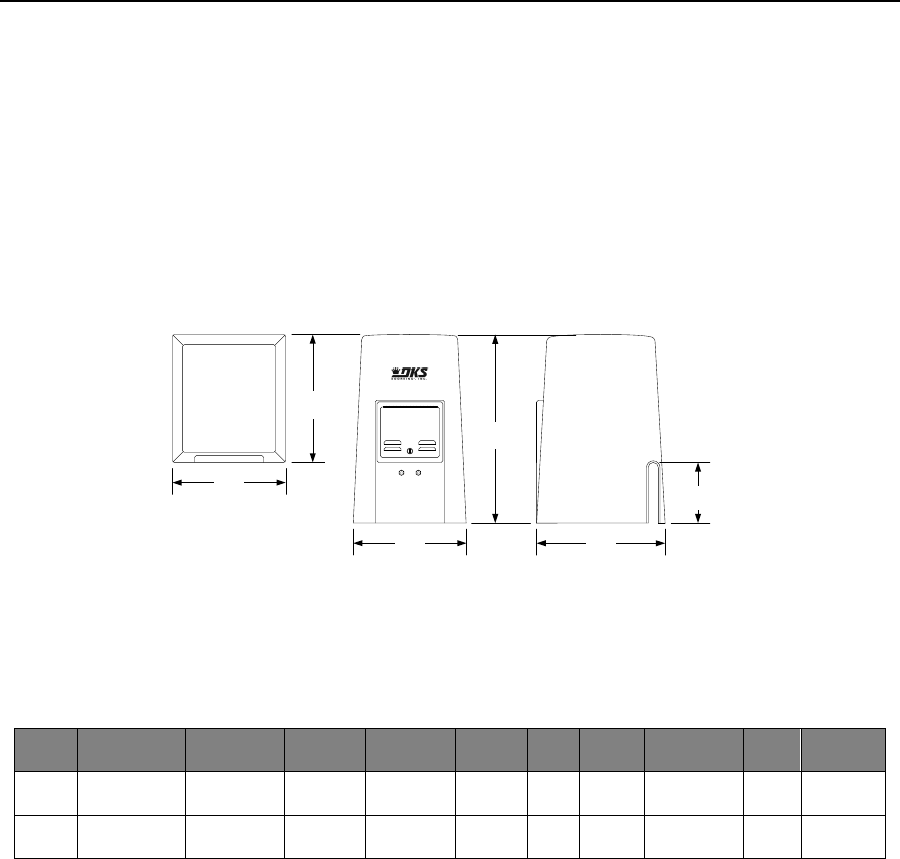
PRICE SCHEDULE A 2.0
Vehicular Traffic Control January 2019
Page 32 Specifications subject to change without notice.
9024 DC Slide Gate Operator
Adjustable Limit Slide Gate Operator
• 30:1 Gear Reducer Drive Train
• Built-in Battery Backup
• Galvanized steel frame
• Opens gate 90° in approximately 16 sec.
• Magnetic lock output
• Overlap feature for bi-parting gates
Page Rev 1/2/19
9024
• Input 115/230 VAC or 24 VDC (Solar)
• Adjustable Limits
• Plug-in Loop Detector Ports
• Gate Tracker Data Output
• Built-in power and reset switches
• 20-Feet (6 m) #40 Chain
16.75
28.00
19.00
9.00
16.75
19.00
425.45 mm
425.45 mm
482.60 mm
482.60 mm
711.20 mm
228.60 mm
Model
Maximum
Gate Weight
Maximum
Gate Length
Mount
Class of
Operation1
Voltage
HP
Power
Outlets
Maximum
Cycles / Day
Loop
Ports2
Adjustable
Clutch
9024 1000 Lbs
453 KG
40 Ft
12.2 m
Pad or
Post5 I, II, III, IV 115/230
VAC 1/2 2 Continuous3,4 2 No
90246 1000 Lbs
453 KG
40 Ft
12.2 m
Pad or
Post5 I, II, III, IV 24 VDC
(Solar) 1/2 0 Up to 1504 2 No
1. I = Residential; II = Commercial; III = Limited Access; IV = Restricted Access
2. Plug-in loop detector ports; open and reverse. DoorKing plug-in loop detectors only.
3. Continuous operation is when AC power is present. Operation on battery backup (7.5 Ah batteries) is limited to approximately 40 cycles.
4. Up to 150 cycles with 18 Ah batteries. Actual number of cycles will vary depending on usage, accessories connected, gate weight, operating
condition of gate, temperature and charge state of the batteries. Charge state of batteries is affected by geographical location of the product
when using solar to recharge the batteries.
5. Requires post mounting kit.
6. Solar powered operators will not support bi-parting (dual) gate operation.

January 2019 PRICE SCHEDULE A 2.0
Vehicular Traffic Control
Specifications subject to change without notice. Page 33
9024 DC Slide Gate Operator
Adjustable Limit Slide Gate Operator
Backup Power Inverters
1000-083 1000 Watt, Pure Sine Wave ....................... 2148.00
1000-045 Inverter Post Mount Kit ................................ 270.00
Includes two (2) 35 AH SLA batteries and can power up to two ½ HP
operators or one (1) 1 HP operator. This version is suitable to be used
with all brands of gate operators. See page 46 for more information.
Bi-Parting (Dual) Gate Interconnection Cable RS 485
9024-136 50-Ft. (15 m) ................................................... 42.00
9024-137 984-Ft. (300 m) ............................................. 662.00
Guarded Guide Rollers & Bracket Assembly
1204-120 Single 3-in (76.2 mm) ..................................... 78.26
1204-122 Dual 3-in (76.2 mm)...................................... 138.00
1204-121 Single 6-in (152.4 mm) ................................... 96.30
1204-123 Dual 6-in (152.4 mm).................................... 170.00
1204-005 Replacement Roller 3-in (76.2 mm) ................ 18.06
See page 37 for more information.
V-Wheels - Max Gate Weight
1201-102 UHMW 4-in (101.6 mm) 500 lb. (227 kg)........ 79.46
1201-105 UHMW 4-in (101.6 mm) 750 lb. (340 kg)...... 108.00
1201-117 Steel 4-in (101.6 mm) 1500 lb. (680 kg) ....... 144.00
See page 36 for more information.
V-Wheels Tandem – Max Gate Weight
1201-012 UHMW 4-in (101.6 mm) 1500 lb. (680 kg) .... 204.00
1201-010 Steel 4-in (101.6 mm) 3000 lb. (1360 kg) ..... 364.00
1201-210 Steel 6-in (152.4 mm) 5000 lb. (2268 kg) ..... 532.00
See page 36 for more information.
Chain Idler Assembly
2600-818 ...................................................................... 102.34
Use with rear‐mounted operators.
End Catch
1204-004 ........................................................................ 60.18
Designed for gates with 2‐inch (50.8 mm) frame.
Choose an Operator
9024-380 115/230 VAC .............................................. 3066.00
Includes two 7.5 Ah batteries for limited backup operation. Order 18
Ah batteries to extend the backup operation cycles.
Includes 50 feet (15 m) of RS 485 interconnection cable for bi‐parting
(dual) gate operation.
9024-381 24 VDC (Solar) ............................................ 2856.00
24 VDC solar input power only (supply your own batteries and solar
charging system or use DKS solar kit).
Solar powered operators will not support bi‐parting (dual) gate
operation.
Choose Entrapment Protection (required) Devices
Use Type B1 (non‐contact) and/or Type B2 (contact) entrapment
protection devices to protect all areas where the risk of entrapment
exist ‐ see pages 42‐43.
Operator will not run without entrapment protection device(s)
connected to the controller board.
Battery / Solar Options
1801-004 12-Volt, 18 Ah Battery1 ................................ 218.00
2000-077 24-Volt, 10 Watt Solar Panel ........................ 364.00
2000-070 Solar Kit2 ....................................................... 850.00
1. Two required for 24 Volt operation.
2. Kit includes two (2) 18 Ah batteries, 10 Watt solar panel and
bracket.
Loops and Loop Detectors
See page 42 for a complete list of all loop detectors, prefabricated
loops and loop accessories available.
Surge Suppression
1879-080 High Voltage (120 VAC) ................................ 156.00
Accessories
9000-015 Post Mount Kit1 ............................................ 662.00
2600-961 Chain Link Fence Gate Bracket ....................... 81.88
1601-154 Heater Kit 120 VAC2 ..................................... 484.00
1601-197 Heater Kit 208/230 VAC2 ............................ 1012.00
1. Includes base plate, mounting posts and hardware.
2. Use if temperature routinely falls below 10°F (‐12°C).
Chain
2600-442 #40 Chain, 20-Ft (6 m) .................................. 156.00
Page Rev 1/2/19

PRICE SCHEDULE A 2.0
Vehicular Traffic Control January 2019
Page 34 Specifications subject to change without notice.
9050 / 9100 Slide Gate Operators
Automatic Magnetic Limits
9050 / 9100
• Self-Adjusting Magnetic Limits
• Built-in clutch
• Plug-in Loop Detector Ports
• Built-in power and reset switches
• Two 115 VAC convenience outlets
• Fail-Safe Configuration
9100
• G90 Galvanized steel frame
• Steel cover
• 20-Feet (6 m) #40 Chain
• Gate tracker data output (9100 only)
• Selectable stop/ reverse function (9100 only)
• Partial open / anti-tailgate feature (9100 only)
Top Front Right Side
12.00 11.50
24.00
12.00
7.00
14.75
11.50
304.80 mm
374.65 mm
292.10 mm
622.30 mm
177.80 mm
3.25
82.55 mm
292.10 mm
304.80 mm
Model
Maximum
Gate Weight
Maximum
Gate Length
Mount
Class of
Operation1
Voltage
HP
Power
Outlets
Maximum
Cycles / Day
Loop
Ports2
Adjustable
Clutch3
9050 500 Lbs
227 KG
16 Ft
4.88 m
Pad or
Post4 I 115 VAC 1/25 2 100 2 Yes
9100 1000 Lbs
453 KG
30 Ft
9.14 m
Pad or
Post4 I, II, III, IV 115 VAC 1/2 2 Continuous 2 Yes
1. I = Residential; II = Commercial; III = Limited Access; IV = Restricted Access
2. Plug-in loop detector ports; open and reverse. DoorKing plug-in loop detectors only.
3. Clutch is not applicable as an entrapment protection device.
4. Requires post mount steel base plate.
5. This is an intermittent duty cycle motor.
Page Rev 1/2/19

January 2019 PRICE SCHEDULE A 2.0
Vehicular Traffic Control
Specifications subject to change without notice. Page 35
9050 / 9100 Slide Gate Operators
Automatic Magnetic Limits
Page Rev 1/2/19
Backup Power Inverters
1000-083 1000 Watt, Pure Sine Wave ....................... 2148.00
1000-045 Inverter Post Mount Kit ................................ 270.00
Includes two (2) 35 AH SLA batteries and can power up to two ½ HP
operators or one (1) 1 HP operator. This version is suitable to be used
with all brands of gate operators. See page 46 for more information.
Bi-Parting (Dual) Gate Interconnection Cable
2600-755 30-Ft. (9.1 m)................................................ 218.00
2600-756 40-Ft. (12.2 m).............................................. 288.00
2600-757 50-Ft. (15.2 m).............................................. 364.00
2600-754 500-Ft. (152.4 m) ........................................ 2890.00
Guarded Guide Rollers & Bracket Assembly
1204-120 Single 3-in (76.2 mm) ..................................... 78.26
1204-122 Dual 3-in (76.2 mm) ..................................... 138.00
1204-121 Single 6-in (152.4 mm) ................................... 96.30
1204-123 Dual 6-in (152.4 mm) ................................... 170.00
1204-005 Replacement Roller 3-in (76.2 mm) ............... 18.06
See page 37 for more information.
V-Wheels - Max Gate Weight
1201-102 UHMW 4-in (101.6 mm) 500 lb. (227 kg) ....... 79.46
1201-105 UHMW 4-in (101.6 mm) 750 lb. (340 kg) ..... 108.00
1201-117 Steel 4-in (101.6 mm) 1500 lb. (680 kg) ....... 144.00
See page 36 for more information.
V-Wheels Tandem – Max Gate Weight
1201-012 UHMW 4-in (101.6 mm) 1500 lb. (680 kg) ... 204.00
1201-010 Steel 4-in (101.6 mm) 3000 lb. (1360 kg) ..... 364.00
1201-210 Steel 6-in (152.4 mm) 5000 lb. (2268 kg) ..... 532.00
See page 36 for more information.
Chain Idler Assembly
2600-818 ...................................................................... 102.34
Use with rear‐mounted operators.
End Catch
1204-004 ........................................................................ 60.18
Designed for gates with 2‐inch (50.8 mm) frame.
Choose an Operator
9050-380 ½ HP ........................................................... 1984.00
9100-380 ½ HP ........................................................... 2890.00
Choose Entrapment Protection (required) Devices
Use Type B1 (non‐contact) and/or Type B2 (contact) entrapment
protection devices to protect all areas where the risk of entrapment
exist ‐ see pages 42‐43.
Operator will not run without entrapment protection device(s)
connected to the controller board.
Loops and Loop Detectors
See page 42 for a complete list of all loop detectors, prefabricated
loops and loop accessories available.
Surge Suppression
1879-080 High Voltage (120 VAC) ................................ 156.00
Accessories
2600-418 Steel Base Plate .............................................. 90.30
2600-970 Base Plate Stop Bracket1 ................................ 60.18
2600-862 Fail-Secure Lock Kit2 ....................................... 31.30
2600-961 Chain Link Fence Gate Bracket ....................... 81.88
1601-154 Heater Kit 120 VAC3 ..................................... 484.00
1. Use with 2600‐418 base plate.
2. Operators come standard in a Fail‐Safe configuration.
3. Use if temperature routinely falls below 10°F (‐12°C).
Chain
2600-442 #40 Chain, 20-Ft (6 m) .................................. 156.00
2600-271 Chain Stop #40, #41 Chain ............................. 30.12
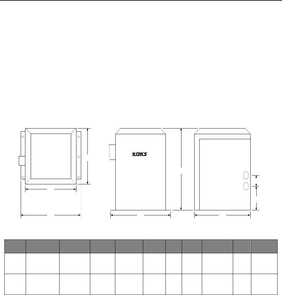
PRICE SCHEDULE A 2.0
Vehicular Traffic Control January 2019
Page 36 Specifications subject to change without notice.
9150 Slide Gate Operators
Automatic Magnetic Limits
9150
• Self-Adjusting Magnetic Limits
• Built-in clutch
• Plug-in Loop Detector Ports
• Built-in power and reset switches
• Two 115 VAC convenience outlets
• Fail-Safe Configuration
• G90 Galvanized steel frame
• Steel cover
• 20-Feet (6 m) #40 Chain
• Gate tracker data output
• Selectable stop/ reverse function
• Partial open / anti-tailgate feature
Model
Maximum
Gate Weight
Maximum
Gate Length
Mount
Class of
Operation1
Voltage2
HP
Power
Outlets
Maximum
Cycles / Day
Loop
Ports2
Adjustable
Clutch3
9150 1000 Lbs
454 KG
30 Ft
9.14 m
Pad or
Post4 I, II, III, IV
115 208
230 460
575 VAC
1/2 2 Continuous 2 Yes
9150 1500 Lbs
680 KG
45 Ft
13.7 m
Pad or
Post4 I, II, III, IV
115 208
230 460
575 VAC
1 2 Continuous 2 Yes
1. I = Residential; II = Commercial; III = Limited Access; IV = Restricted Access.
2. High voltage kit (P/N 2600-266) required for 208 Volt and higher.
3. Plug-in loop detector ports; open and reverse. DoorKing plug-in loop detectors only.
4. Clutch is not applicable as an entrapment protection device.
5. Requires post mount steel base plate.
Page Rev 1/2/19
Top Front Right Side
18.00 16.75
24.50
15.25
7.13
18.00
16.75
425.45 mm
387.35 mm
457.20 mm 457.20 mm 425.45 mm
622.30 mm
181.10 mm
3.25
82.55 mm

January 2019 PRICE SCHEDULE A 2.0
Vehicular Traffic Control
Specifications subject to change without notice. Page 37
9150 Slide Gate Operators
Automatic Magnetic Limits
Choose an Operator
9150-384 ½ HP ........................................................... 3094.00
9150-380 1 HP ............................................................ 3732.00
High Voltage
2600-266 High Voltage Kit ........................................... 640.00
Allows the operator to be powered from 208, 230, 460 or 575 VAC
source voltage.
Choose Entrapment Protection (required) Devices
Use Type B1 (non‐contact) and/or Type B2 (contact) entrapment
protection devices to protect all areas where the risk of entrapment
exist ‐ see pages 42‐43.
Operator will not run without entrapment protection device(s)
connected to the controller board.
Loops and Loop Detectors
See page 42 for a complete list of all loop detectors, prefabricated
loops and loop accessories available.
Surge Suppression
1879-080 High Voltage (120 VAC) ................................ 156.00
Accessories
2600-495 Steel Base Plate ............................................ 302.00
2600-970 Base Plate Stop Bracket1 ................................ 60.18
2600-865 Fail-Secure Lock Kit2 ....................................... 38.54
2600-961 Chain Link Fence Gate Bracket ....................... 81.88
1601-154 Heater Kit 120 VAC3 ..................................... 484.00
1601-197 Heater Kit 208/230 VAC3 ............................ 1012.00
1601-198 Heater Kit 480 VAC3 ................................... 1012.00
1. Use with 2600‐495 base plate.
2. Operators come standard in a Fail‐Safe configuration.
3. Use if temperature routinely falls below 10°F (‐12°C).
Chain
2600-442 #40 Chain, 20-Ft (6 m) .................................. 156.00
2600-271 Chain Stop #40, #41 Chain ............................. 30.12
Page Rev 1/2/19
Backup Power Inverters
1000-083 1000 Watt, Pure Sine Wave ....................... 2148.00
1000-045 Inverter Post Mount Kit ................................ 270.00
Includes two (2) 35 AH SLA batteries and can power up to two ½ HP
operators or one (1) 1 HP operator. This version is suitable to be used
with all brands of gate operators. See page 46 for more information.
Bi-Parting (Dual) Gate Interconnection Cable
2600-755 30-Ft. (9.1 m)................................................ 218.00
2600-756 40-Ft. (12.2 m).............................................. 288.00
2600-757 50-Ft. (15.2 m).............................................. 364.00
2600-754 500-Ft. (152.4 m) ........................................ 2890.00
Guarded Guide Rollers & Bracket Assembly
1204-120 Single 3-in (76.2 mm) ..................................... 78.26
1204-122 Dual 3-in (76.2 mm) ..................................... 138.00
1204-121 Single 6-in (152.4 mm) ................................... 96.30
1204-123 Dual 6-in (152.4 mm) ................................... 170.00
1204-005 Replacement Roller 3-in (76.2 mm) ............... 18.06
See page 37 for more information.
V-Wheels - Max Gate Weight
1201-102 UHMW 4-in (101.6 mm) 500 lb. (227 kg) ....... 79.46
1201-105 UHMW 4-in (101.6 mm) 750 lb. (340 kg) ..... 108.00
1201-117 Steel 4-in (101.6 mm) 1500 lb. (680 kg) ....... 144.00
See page 36 for more information.
V-Wheels Tandem – Max Gate Weight
1201-012 UHMW 4-in (101.6 mm) 1500 lb. (680 kg) ... 204.00
1201-010 Steel 4-in (101.6 mm) 3000 lb. (1360 kg) ..... 364.00
1201-210 Steel 6-in (152.4 mm) 5000 lb. (2268 kg) ..... 532.00
See page 36 for more information.
Chain Idler Assembly
2600-818 ...................................................................... 102.34
Use with rear‐mounted operators.
End Catch
1204-004 ........................................................................ 60.18
Designed for gates with 2‐inch (50.8 mm) frame.
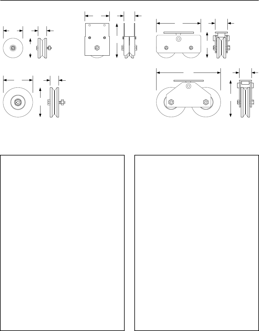
PRICE SCHEDULE A 2.0
Vehicular Traffic Control January 2019
Page 38 Specifications subject to change without notice.
Slide Gate Accessories
V-Wheels
4.00
102 mm
4.00
102 mm
6.00
V-Wheels
152 mm
6.00
7.00
2.25
152 mm
5.00
57 mm127 mm
178 mm
9.00 2.50
2.5013.00
1.75
44 mm
1.75
44 mm
229 mm
330 mm
57 mm
57 mm
5.25
133 mm
7.50
190 mm
V-Wheel Assembly Tandem V-Wheel Assembly
4-Inch (102 mm) V-Wheels
1201-004 UHMW w/sleeve bearing................................ 43.34
• 500 Lb. (226 Kg) maximum weight
1201-006 UHMW w/sealed bearing ............................... 60.18
• 750 Lb. (340 Kg) maximum weight
1201-016 Steel w/sealed bearing ................................. 108.00
• 1500 Lb. (680 Kg) maximum weight
4-Inch (102 mm) V-Wheel Assemblies1
1201-102 UHMW w/sleeve bearing................................ 79.46
• 500 Lb. (226 Kg) maximum weight
1201-105 UHMW w/sealed bearing ............................. 108.00
• 750 Lb. (340 Kg) maximum weight
1201-117 Steel w/sealed bearing ................................. 144.00
• 1500 Lb. (680 Kg) maximum weight
1. Assemblies include wheel guarding as required by industry safety standards.
4-Inch (102 mm) Tandem V-Wheel Assemblies
1201-012 UHMW w/sealed bearing ............................. 204.00
• 1500 Lb. (680 Kg) maximum weight
1201-010 Steel w/sealed bearing ................................. 364.00
• 3000 Lb. (1360 Kg) maximum weight
6-Inch (152 mm) V-Wheels
1201-000 Steel w/sealed bearing ................................ 212.00
• 2500 Lb. (1133 Kg) maximum weight
6-Inch (152 mm) Tandem V-Wheel Assembly
1201-210 Steel w/sealed bearing ................................ 532.00
• 5000 Lb. (2267 Kg) maximum weight
Page Rev 1/2/19
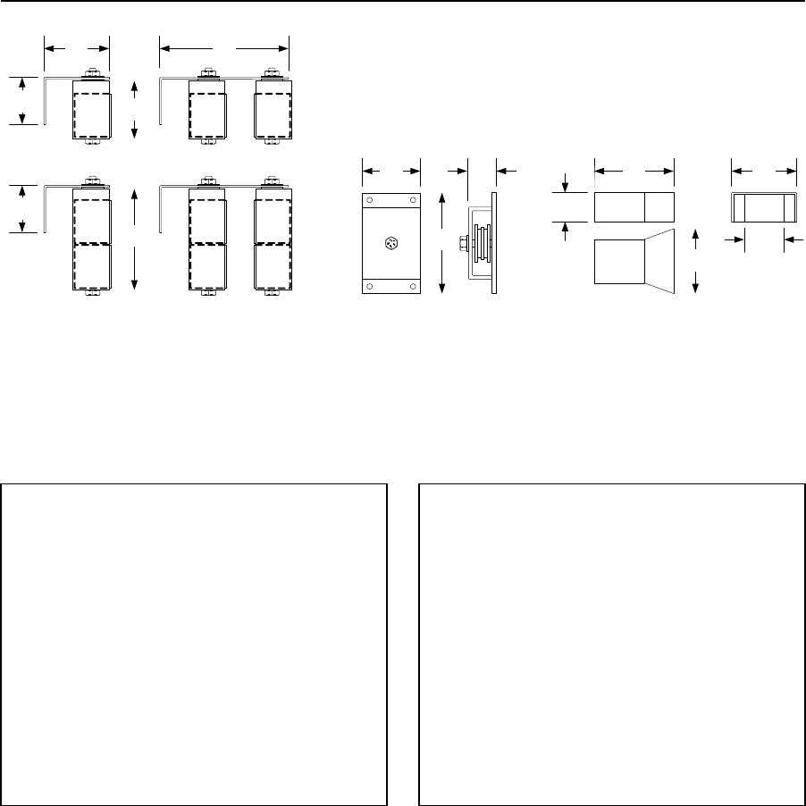
January 2019 PRICE SCHEDULE A 2.0
Vehicular Traffic Control
Specifications subject to change without notice. Page 39
Slide Gate Accessories
Guide Rollers, Chain Idler, End Catch
4.50
4.00
114 mm
4.00
1204-120
7.00
2.00
51 mm
8.88
3.25
3.25
7.00
225 mm
82 mm 102 mm
82 mm
179 mm
1204-122
1204-121 1204-123
102 mm
179 mm
2600-818
5.50 4.50
4.50
140 mm
114 mm
114 mm
2.00
51 mm
1204-004
2.75
70 mm
3-Inch (76 mm) Guide Roller Assemblies1
1204-120 Single ............................................................. 78.26
1204-122 Dual ............................................................. 138.00
1. Assemblies include roller guarding as required by industry safety standards.
6-Inch (152 mm) Guide Roller Assemblies1
1204-121 Single ............................................................. 96.30
1204-123 Dual ............................................................. 170.00
1. Assemblies include roller guarding as required by industry safety standards.
3-Inch (76 mm) Replacement Roller
1204-005 ........................................................................ 18.06
Chain Idler Assembly
2600-818 ...................................................................... 102.34
• Use this with rear-mounted slide gate operators. Works
with #40 and #41 chain.
End Catch
1204-004 ........................................................................ 60.18
• Use with 2-inch (51 mm) gate frame.
Page Rev 1/2/19

PRICE SCHEDULE A 2.0
Vehicular Traffic Control January 2019
Page 40 Specifications subject to change without notice.
Slide Gate Operator Parts & Accessories
Miscellaneous Parts & Accessories
Circuit Boards
4100-018 ...................................................................... 516.00
Used in model 9024
4405-018 ...................................................................... 608.00
Used in model 9000
4602-018 ...................................................................... 744.00
Used in models 9100, 9150
4702-018 ...................................................................... 516.00
Used in models 9050
Chain
2600-441 #41 Chain – 20 Ft (6 m) ................................. 122.00
2600-442 #40 Chain – 20 Ft (6 m) ................................. 156.00
2600-443 #41 Chain Nickel Plated – 10 Ft (3 m) ........... 106.00
2600-444 #40 Chain Nickel Plated – 10 Ft (3 m) ........... 142.00
2600-271 Chain Stop for #40 and #41 Chain................... 30.12
2600-961 Chain Link Fence Gate Bracket........................ 81.88
Base Plates
2600-418 Steel Base Plate .............................................. 90.30
Use with 9050 and 9100 operators
2600-495 Steel Base Plate ............................................ 302.00
Use with 9150 operator
2600-970 Base Plate Stop Bracket .................................. 60.18
Use with 2600-418 and 2600-495
Bi-Parting Connection Cable
2600-754 Primary / Secondary Cable ......................... 2890.00
500-ft (152.4 m) roll
9024-137 RS 485 Cable ................................................. 662.00
984-ft (300 m) roll
Page Rev 1/2/19
January 2019 PRICE SCHEDULE A 2.0
Vehicular Traffic Control
Specifications subject to change without notice. Page 41
Blank Page
Page Rev 1/2/19
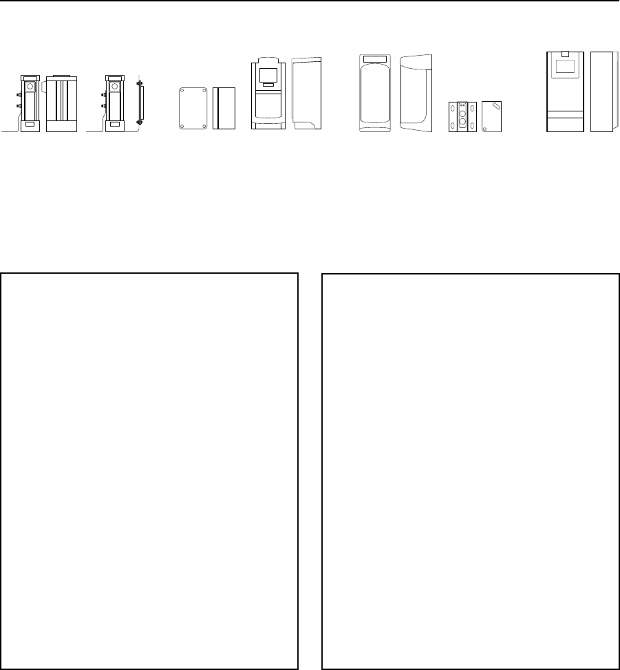
PRICE SCHEDULE A 2.0
Vehicular Traffic Control January 2019
Page 42 Specifications subject to change without notice.
Entrapment Prevention Devices
Non-contact Sensors Type B1
8080-050 8080-051 8080-052 8080-053 8080-054 8080-056
8080-055
Thru-Beam Devices
8080-050 (ME-PG) ........................................................ 546.00
• 100 Ft. (30 m) maximum sensing distance.
• Receiver (RX-R) 7-30 VAC / 10-42 VDC.
• Transmitter (EM-W) 7-30 VAC / 10-42 VDC.
8080-052 (EMX MON) .................................................. 546.00
• 115 Ft. (35 m) maximum sensing distance.
• 12-24 VAC / 6-35 VDC.
• Includes hood.
8080-054 (Seco-Larm E960-D90GQ) ............................. 546.00
• 90 Ft. (27 m) maximum sensing distance.
• 12-30 VAC / VDC.
Photo-Reflective Devices
8080-051 (ME-RG) ....................................................... 502.00
• 30 Ft. (9 m) maximum sensing distance.
• Receiver 7-30 VAC / 10-42 VDC.
8080-053 (EMX IRB-RET) .............................................. 502.00
• 60 Ft. (18 m) maximum sensing distance.
• 12-24 VAC / 6-35 VDC.
8080-055 (Seco-Larm E936-S45RRGQ) ......................... 502.00
• 45 Ft. (14 m) maximum sensing distance.
• 12-30 VAC / VDC.
8080-056 (Omron E3K) ................................................ 502.00
• 33 Ft. (10 m) maximum sensing distance.
• 24-240 VAC / VDC.
Page Rev 1/2/19
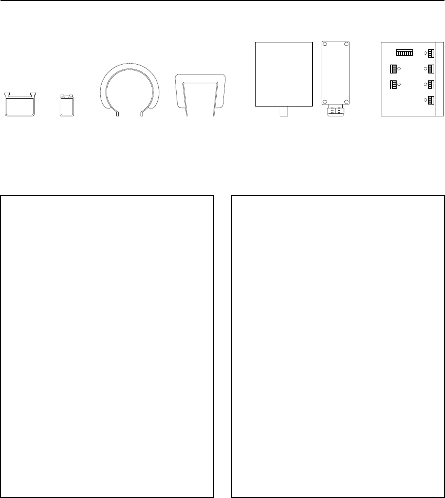
January 2019 PRICE SCHEDULE A 2.0
Vehicular Traffic Control
Specifications subject to change without notice. Page 43
Entrapment Prevention Devices
Contact Sensors Type B2
O UT A
POWE R
O UT B
IN
3
IN
4
IN5
IN6
IN1
IN
2
RBANDRX
RBANDTX
8080-070
8080-090 8080-071
8080-091 8080-065
8080-085 8080-066
8080-086 8080-008 8080-006 8080-079
2-Wire Contact Edge with 10K Termination
8080-071 6 Ft. (1.8 m) ME111-T2 ................................ 384.00
• Ideal for barrier arms, includes mounting channel.
8080-070 5 Ft. (1.5 m) ME123-T2 ................................ 384.00
• Includes mounting channel.
8080-065 5 Ft. (1.5 m) MGR20-T2................................ 422.00
• Fits on 2 in (51 mm) round post.
8080-066 5 Ft. (1.5 m) MGS20-T2 ................................ 422.00
• Fits on 2 in (51 mm) square post.
4-Wire Contact Edge1
8080-091 6 Ft. (1.8 m) ME111 ..................................... 384.00
• Ideal for barrier arms, includes mounting channel.
8080-090 5 Ft. (1.5 m) ME123 ..................................... 384.00
• Includes mounting channel.
8080-085 5 Ft. (1.5 m) MGR20 ..................................... 422.00
• Fits on 2 in (51 mm) round post.
8080-086 5 Ft. (1.5 m) MGS20 ..................................... 422.00
• Fits on 2 in (51 mm) square post.
1. 4-wire edges do not have 10K termination and are designed to be used wired
in series with the 2-wire T2 edges.
Contact Sensor Accessories
8080-079 Multiple Input Module (MIM 62) ................. 870.00
• Monitors up to six (6) external contact edges.
8080-008 Wireless Monitored Link (RB-G-K10)1 .......... 526.00
• Receiver: 12-24 VAC / VDC.
• Transmitter: 3.6 VDC / 2 AA Lithium.
• Receiver can monitor up to six (6) edges.
1. Kit includes receiver and one (1) RB-TX-10 transmitter.
8080-006 Monitored Transmitter (RB-TX-10) .............. 262.00
Page Rev 1/2/19
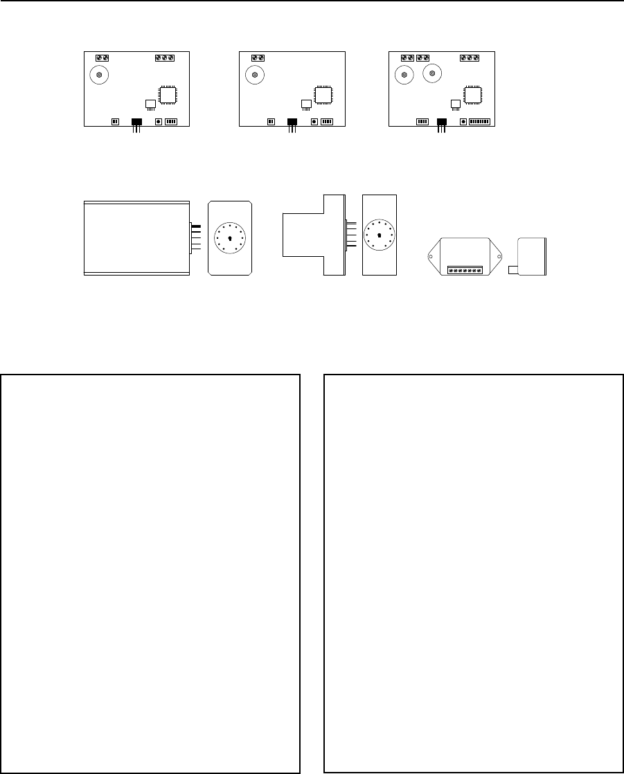
PRICE SCHEDULE A 2.0
Vehicular Traffic Control January 2019
Page 44 Specifications subject to change without notice.
Vehicle Protection
Loop Detectors and Loops
9402-0509402-0449402-045 / 9402-047
9409-010 / 9415-0109410-010 / 9416-010
9411-010
DKS Plug-In Loop Detectors
9411-010 Single Channel + Aux Relay ........................... 250.00
9410-010 Single Channel .............................................. 232.00
9409-010 Two Channel ................................................. 436.00
9415-010 Two Channel Low Power Draw ..................... 458.00
9416-010 Single Channel Low Power Draw .................. 262.00
Reno A&E Wired Loop Detectors1, 2
9402-045 24 VAC / 12-24 VDC ...................................... 302.00
9402-047 120 VAC ........................................................ 302.00
9402-061 Wire Harness .................................................. 26.50
Carlo Gavazzi Wired Loop Detectors1, 2
9402-044 24 VAC / VDC ................................................ 222.00
9402-061 Wire Harness .................................................. 26.50
Diablo Wired Loop Detectors
9402-050 10-30 VAC / VDC Low Power Draw ............... 302.00
1. Detectors have two (2) relay outputs.
2. 9402-061 harness required.
Loop Wire – 18 AWG – XLPE Insulation
9402-076 500 Ft. (152 m) Black .................................... 194.00
9402-077 1000 Ft. (304 m) Black .................................. 302.00
9402-078 500 Ft. (152 m) Blue ..................................... 194.00
9402-079 1000 Ft. (304 m) Blue ................................... 302.00
9402-080 500 Ft. (152 m) Red ...................................... 194.00
9402-081 1000 Ft. (304 m) Red .................................... 302.00
Prefabricated Loops1
9401-060 Blue Wire ..................................................... 302.00
9401-061 Yellow Wire .................................................. 302.00
9401-062 Red Wire ...................................................... 302.00
24 Ft. (7 m) circumference, 50 Ft. (15 M) lead-in wire.
Loop Accessories
9401-045 Meg-Ohm Test Meter .................................. 542.00
Page Rev 1/2/19
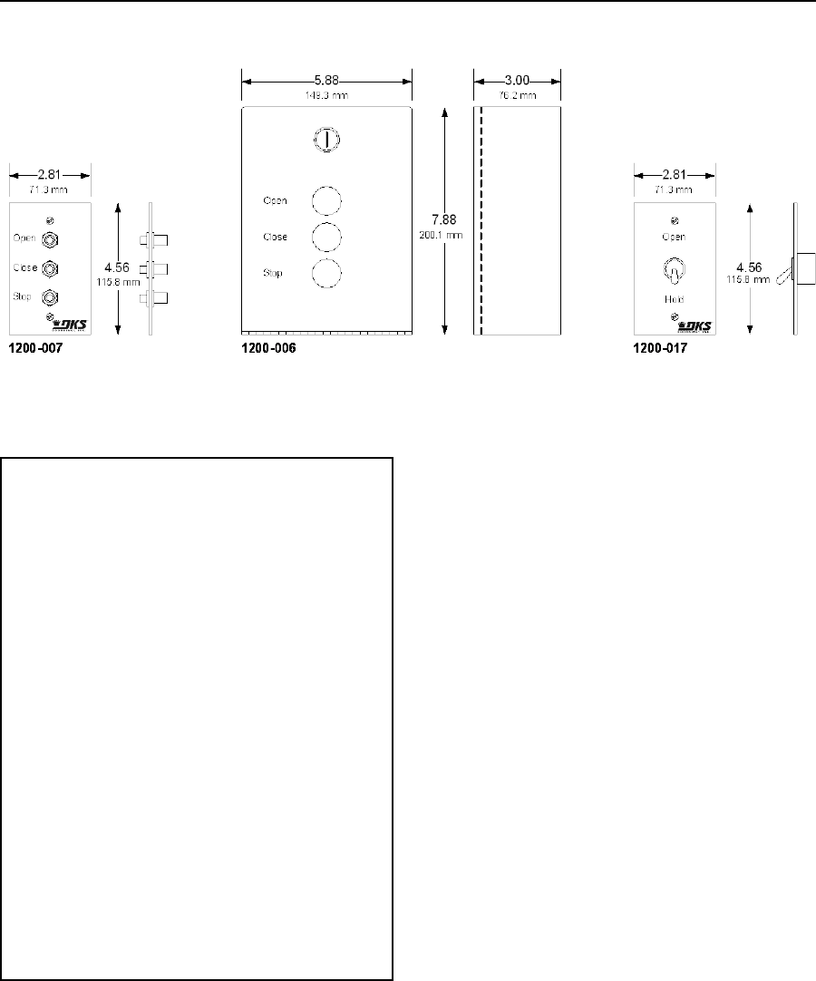
January 2019 PRICE SCHEDULE A 2.0
Vehicular Traffic Control
Specifications subject to change without notice. Page 45
Control Stations
Manual Control
3-Button Control1
1200-007 Indoor use only ............................................... 90.30
• Mounts into single-gang electrical box.
1200-006 Indoor or Outdoor use .................................. 164.00
• Wall mount
1. These control stations use a normally open stop circuit and can only be used
with the following models: 6050, 6100, 9100, 9150.
Toggle Control
1200-017 Indoor use only ............................................... 54.18
• Mounts into single-gang electrical box
Page Rev 1/2/19
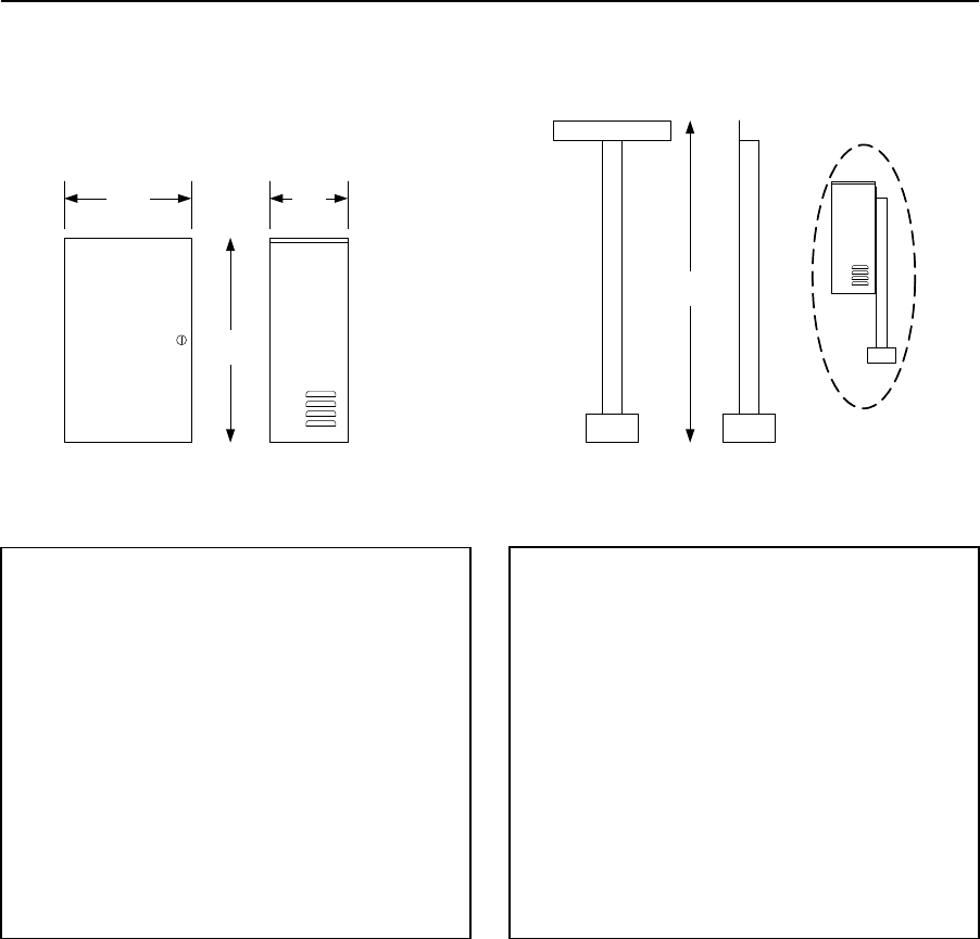
PRICE SCHEDULE A 2.0
Vehicular Traffic Control January 2019
Page 46 Specifications subject to change without notice.
Model 1000
Back-up Power / Inverter
21.00
13.00 8.00
33.00
330 mm
533 mm
203 mm
838 mm
1000-083 1000-045
Model 1000 Power Inverter
1000-083 Pure Sine Wave, 1000 Watt ........................ 2148.00
• Includes two (2) batteries.
• Will power two (2) ½ HP operators or a single 1 HP
operator.
• Suitable for use with all DoorKing gate operators and
most other brands.
Accessories
1000-045 Post Mount Kit ............................................. 270.00
1801-005 12-Volt, 35 Ah SLA Battery ........................... 278.00
1000-044 Battery Cable Set ........................................... 51.32
Page Rev 1/2/19
Page Rev 1/2/19

January 2019 PRICE SCHEDULE A 2.0
Telephone Entry & Access Control Systems
Specifications subject to change without notice. Page 1
Section A2
This Price Schedule is effective January 7, 2019.
Telephone Entry & Access Control Systems
Date Page Comment
1-2-19
All
January, 2019 Price Schedule update.

PRICE SCHEDULE A 2.0
Telephone Entry & Access Control Systems January 2019
Page 2 Specifications subject to change without notice.
Entry System Connection Options – Your Choice
For more information, please visit:
http://www.doorking.com/connect and http://www.doorking.com/imserver and http://www.doorking.com/cellular
4G-LTE Cellular Service (Plug & Play)
• Voice and Programming (wireless via the cellular network)
• DKS Cellular (subscription based service)
Internet (VoIP) Connection (Plug & Play)
• Voice and Programming (wired connection)
• DKS Internet or VoIP subscription service required
• Requires 1830-186 Network Adapter for programming1
• Requires 1815-530 VoIP adapter for DKS VoIP1 or use third party VoIP adapter2
• Plug & Play for LAN and WAN connections 2334-0803
1: Subscription service.
2: DoorKing does not guarantee third party VoIP service. Third party VoIP subscription may be required.
3: Combines 1830-186, 1815-530 and Ethernet switch into a single enclosure.
Internet (VoIP) Connection (Manual IP Configuration)
• Voice and Programming (wired connection)
• Manual setup – requires 1830-185 Network adapter
• Manual setup required: determine Default Gateway, set your IP address, setup Port Forwarding,
configure Firewall for access, order Static IP address from internet provider or setup DDNS host
account
• Compatible with most VoIP providers1
1: DoorKing does not guarantee third party VoIP service. Third party VoIP subscription may be required.
Land Line Telephone Service3 (POTS line, Cable or Fiber1)
• Voice and Programming (wired connection)
• Programming options:
o IM Server Modem (subscription based service)
o Modem to Modem2
1: Not applicable if Cable or Fiber is a cloud based telephone service.
2: Not compatible with all modems. Requires phone line and modem at programming PC.
3: DoorKing does not recommend using POTS (Plain Old Telephone Service) as a connection option and does not guarantee
modem connections as many phone company services and switches no longer support modem communications.
TTY Connection Options
• Allows hearing impaired persons to connect their TTY device to the telephone entry system.
• P/N 1830-310 is factory installed at time of order.
• P/N 1830-315 is an add-on device that can be added to the telephone entry system at any time.
January 2019 PRICE SCHEDULE A 2.0
Telephone Entry & Access Control Systems
Specifications subject to change without notice. Page 3
Table of Contents
Telephone Entry & Access Control
Model 1802 ............................................................................................................................................................ 4
Model 1803 ............................................................................................................................................................ 6
Model 1808 ............................................................................................................................................................ 8
Model 1810 .......................................................................................................................................................... 10
Model 1812 .......................................................................................................................................................... 12
Model 1819 .......................................................................................................................................................... 14
Model 1816/1820 ................................................................................................................................................. 16
Model 1833 80 Series ........................................................................................................................................... 18
Model 1834 90 Series ........................................................................................................................................... 20
Model 1834 80 Series ........................................................................................................................................... 22
Model 1835 90 Series ........................................................................................................................................... 24
Model 1835 80 Series ........................................................................................................................................... 26
Model 1837 90 Series ........................................................................................................................................... 28
Model 1837 80 Series ........................................................................................................................................... 30
Model 1838 .......................................................................................................................................................... 32
Model 1838 Access Plus ....................................................................................................................................... 34
Accessories
Connection Options .............................................................................................................................................. 36
Elevator Control .................................................................................................................................................... 37
Tracker Expansion Boards .................................................................................................................................... 38
Wireless Kits for Tracker Expansion Boards ......................................................................................................... 39
Telephone Entry Systems Mounting Kits .............................................................................................................. 40
Light Kits ............................................................................................................................................................... 41
Add-on Directories ............................................................................................................................................... 42
Utility Enclosures .................................................................................................................................................. 43
Accessories ........................................................................................................................................................... 44
Replacement Components ................................................................................................................................... 45
Page Rev 1/2/19
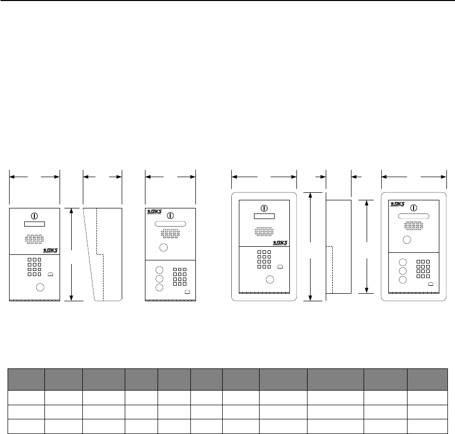
PRICE SCHEDULE A 2.0
Telephone Entry & Access Control Systems January 2019
Page 4 Specifications subject to change without notice.
1802 Telephone Entry System
Residential, Commercial
1802 AP (Access Plus) ONLY
• Control up to 8 entry points
• IP Addressable
• PC Programmable
• 2-Digit directory codes
• 20-digit dialing
• Includes 16 VAC power transformer
1802 / 1802 EPD
• Hands free full duplex voice communication
• Programmable Directory Codes (1-4 digits)
• 16-digit dialing
• Includes 16 VAC power transformer
• Backlit keypad and A-Z-CALL buttons (EPD only)
Model
Phone
Numbers
Directory6
Names
Entry
Codes1
Device
Codes2
Relays
Auxiliary
Inputs3
Expansion4
PC
Programmable5
Temporary
Codes
Holiday
Schedules
1802 600 N/A 1000 0 2 1 No No 5 No
1802EPD 100 100 100 0 2 1 No No 5 No
1802AP 27 N/A 50 100 2 2 6 Max Yes 10 Yes
1. Entry codes are four (4) digits only and are not the same as device codes. Entry codes grant access when entered on the entry system keypad (or
secondary keypad) only.
2. Device codes refer to any five (5) digit RS-485 device used to access an entry point, such as cards, transmitters or PINs (Personal Identification
Number). Five (5) digit device codes can also be used on the system keypad.
3. 1802 and 1802EPD, auxiliary input allows a switch closure to activate relay 2, or can be set to auto-dial a preprogrammed telephone number.
1802 AP uses a standard RS-485 data input.
4. Six (6) additional entry points can be controlled via RS-485 card readers, AVID tag readers, RF receivers or digital keypads.
5. AP Programming software available for free download at doorking.com.
6. Single line 16 character 5/16 LCD display.
Page Rev 1/2/19
123
456
789
*0 #
A
Z
Call
123
456
789
*0 #
A
Z
Call
1 2 3
4 5 6
7 8 9
*0 #
123
456
789
*0 #
6.50 5.00 6.50 8.38 3.25 8.38
12.00 14.00 12.00
165.10 mm 127.00 mm 165.10 mm 212.85 mm 82.55 mm 212.85 mm
304.80 mm 355.60 mm 304.80 mm
Surface Mount
1802 / 1802 AP Surface Mount
1802 EPD Flush Mount
1802 Flush Mount
1802 EPD

January 2019 PRICE SCHEDULE A 2.0
Telephone Entry & Access Control Systems
Specifications subject to change without notice. Page 5
1802 Telephone Entry System
Residential, Commercial
1802 Telephone Entry Systems
1802-082 Surface Mount ........................................... 1230.00
1802-089 Flush Mount ............................................... 1542.00
1802-090 Surface Mount EPD .................................... 1506.00
1802-091 Flush Mount EPD........................................ 1818.00
1802-092 Surface Mount AP (Access Plus) ................. 1926.00
Service Connection Options
1800-081 Cellular Voice + Data1,2 ................................. 654.00
1801-080 Cellular Voice Only1,3 ................................... 434.00
1 - Cellular service plan required (provided by DoorKing).
2 - Use with 1802 AP model.
3 - Use with 1802 and 1802 EPD models.
1802 Lobby Panel
1802-083 ...................................................................... 916.00
1802-094 .................................................................... 1226.00
Lobby panels can only be used with the 1816 or 1820 telephone
intercom system. They cannot be connected directly to telephone
service.
Accessories
1701-080 20-Name Directory....................................... 156.00
1702-080 60-Name Directory....................................... 228.00
1710-080 200-Name Directory Surface Mount ............ 484.00
1710-081 200-Name Directory Flush Mount................ 484.00
1506-081 Secondary Keypad surface mount................ 444.00
1506-091 Secondary Keypad flush mount ................... 576.00
1804-193 External Speaker .......................................... 202.00
1801-008 Backup Battery 12-Volt .8 Ah ......................... 91.52
2600-588 Heater Kit (1802, 1802 AP) .............................. 238.00
2600-582 LCD Heater (1802 EPD) ..................................... 52.98
1812-145 CCTV Color Camera .................................... 1022.00
1807-012 Handset Kit (surface mount only) ..................... 422.00
1802-111 Post Mount Adapter Plate1 .......................... 166.00
1. Required if mounting 1802 to gooseneck post.
1830-310 TTY Add-on Factory Installed ....................... 312.00
1830-315 TTY Add-on Kit ............................................. 348.00
1802 AP (ACCESS PLUS ONLY) Expansion Options
2354-010 Conversion Board ......................................... 180.00
1815-235 Conversion Board w/Enclosure .................... 316.00
Converts 26-bit Wiegand to RS-485. Requires 12-16 VDC power.
1812-020 12-VDC, 1A Transformer ................................ 51.62
1200-080 Transformer Box........................................... 234.00
1816-083 Intercom Phone Expansion......................... 1144.00
The 1816-083 expands the “No Phone Line” telephone intercom
interface on Access Plus systems from a single phone line up to 11
phone lines. The system can be further expanded to interface with up
to a maximum of 23 phone lines.
RS-485 Card Readers (ACCESS PLUS ONLY)
1815-332 DK Prox Reader ............................................ 432.00
1815-232 ID Tech Reader ............................................. 504.00
1815-233 AWID Reader ................................................ 516.00
1815-234 HID Reader ................................................... 916.00
RS-485 Keypads (ACCESS PLUS ONLY)
1513-081 Surface Mount.............................................. 542.00
1513-082 Flush Mount ................................................. 674.00
RS-485 RF Controls (ACCESS PLUS ONLY)
8053-080 MicroPlus Receiver ....................................... 218.00
Page Rev 1/2/19
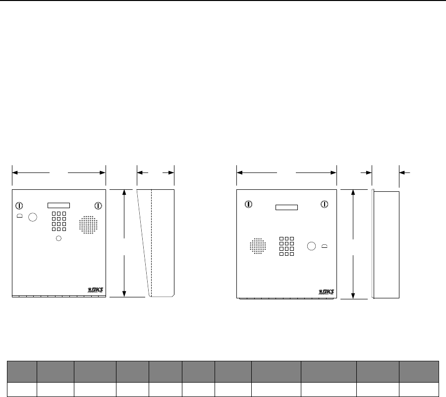
PRICE SCHEDULE A 2.0
Telephone Entry & Access Control Systems January 2019
Page 6 Specifications subject to change without notice.
1803 Telephone Entry System
Residential, Commercial
Page Rev 1/2/19
13.00
1 2 3
4 5 6
7 8 9
*0 #
4.50
13.25
11.25 12.00
Surface Mount
3.25
Flush Mount
285.75 mm
330.20 mm 336.55 mm
304.80 mm 82.55 mm
1 2 3
4 5 6
7 8 9
*0 #
114.30 mm
1803
• Hands free full duplex voice communication
• Programmable Directory Codes (1-4 digits)
• 16-digit dialing
• Includes 16 VAC power transformer
• Stainless steel faceplate
• Galvanized steel sub-plate
• Metal keypads and buttons
• Postal lock provision
Model
Phone
Numbers
Directory
Names
Entry
Codes1
Device
Codes2
Relays
Auxiliary
Inputs3
Expansion4
PC
Programmable5
Temporary
Codes
Holiday
Schedules
1803 600 N/A 1000 0 2 1 No No 5 No
1. Entry codes are four (4) digits only and are not the same as device codes. Entry codes grant access when entered on the entry system keypad (or
secondary keypad) only.
2. Device codes are not used with the 1803.
3. 1803 auxiliary input allows a switch closure to activate relay 2, or can be set to auto-dial a preprogrammed telephone number.

January 2019 PRICE SCHEDULE A 2.0
Telephone Entry & Access Control Systems
Specifications subject to change without notice. Page 7
1803 Telephone Entry System
Residential, Commercial
Page Rev 1/2/19
1803 Telephone Entry Systems
1803-080 Surface Mount ........................................... 1614.00
1803-084 Flush Mount ............................................... 1614.00
1803 Lobby Panels
1803-090 Surface Mount ........................................... 1072.00
1803-092 Flush Mount ............................................... 1072.00
Lobby panels can only be used with the 1816 or 1820 telephone
intercom system. They cannot be connected directly to telephone
service.
Service Connection Options
1801-080 Cellular Voice Only1 ..................................... 434.00
1 - Cellular service plan required (provided by DoorKing)
Mounting Accessories
1803-150 Surface Mount Trim Ring Black .................... 236.00
1814-165 Flush Mount Kit Stainless Steel .................... 396.00
Accessories
1701-080 20-Name Directory ....................................... 156.00
1702-080 60-Name Directory ....................................... 228.00
1710-080 Large Directory Surface Mount .................... 484.00
1710-081 Large Directory Flush Mount ........................ 484.00
1506-081 Secondary Keypad surface mount ................ 444.00
1506-091 Secondary Keypad flush mount .................... 576.00
1720-080 LED Light Kit ................................................. 444.00
1804-193 External Speaker .......................................... 202.00
1801-008 Backup Battery 12-Volt .8 Ah ......................... 91.52
2600-584 Heater Kit ..................................................... 170.00
1812-145 CCTV Color Camera .................................... 1022.00
1807-012 Handset Kit (surface mount only) ..................... 422.00
1830-310 TTY Add-on Factory Installed ........................ 312.00
1830-315 TTY Add-on Kit .............................................. 348.00
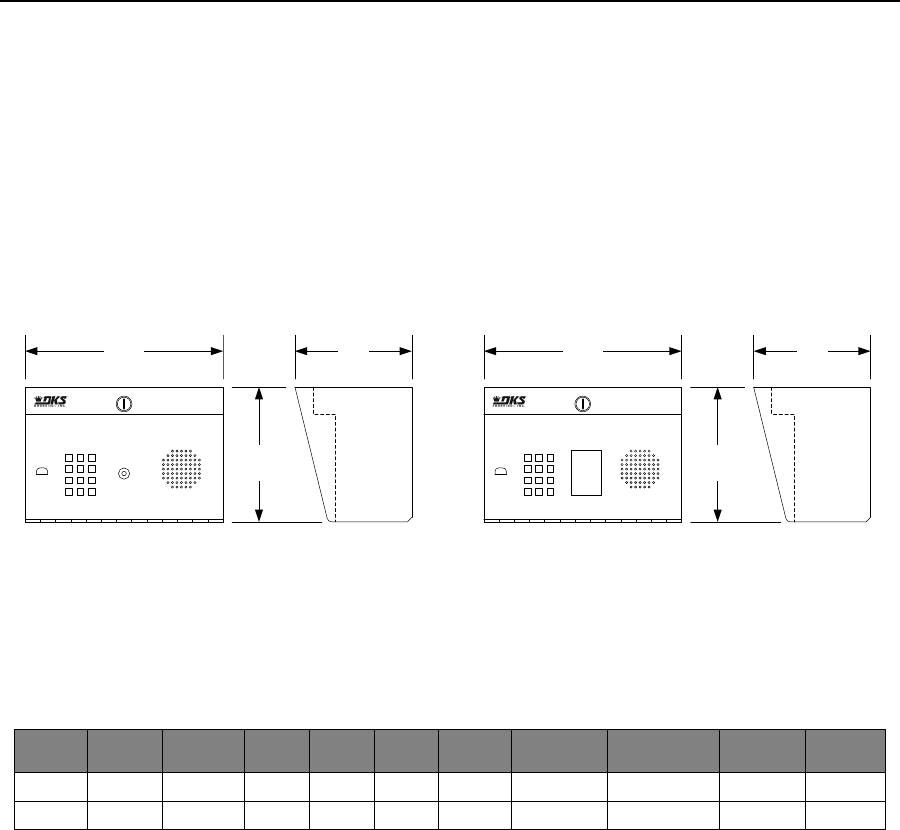
PRICE SCHEDULE A 2.0
Telephone Entry & Access Control Systems January 2019
Page 8 Specifications subject to change without notice.
1808 Telephone Entry System
Residential, Commercial
1808
• Hands free full duplex voice communication
• Programmable Directory Codes (1-4 digits)
• 16-digit dialing
• Includes 16 VAC power transformer
1808 AP (Access Plus) ONLY
• Control up to 8 entry points
• IP Addressable
• PC Programmable
• 2-Digit directory codes
• 20-digit dialing
• Includes 16 VAC power transformer
7.50
6.50
1 2 3
4 5 6
7 8 9
*0 #
11.00
1 2 3
4 5 6
7 8 9
*0 #
Push Button
To Call
Surface Mount
1808 Surface Mount w/Directory
1808 / 1808 AP
6.5011.00
7.50
279.40 mm 165.10 mm 279.40 mm 165.10 mm
190.50 mm190.50 mm
Model
Phone
Numbers
Directory
Names
Entry
Codes1
Device
Codes2
Relays
Auxiliary
Inputs3
Expansion4
PC
Programmable5
Temporary
Codes
Holiday
Schedules
1808 600 N/A 1000 0 2 1 No No 5 No
1808AP 27 N/A 50 100 2 2 6 Max Yes 10 Yes
1. Entry codes are four (4) digits only and are not the same as device codes. Entry codes grant access when entered on the entry system keypad (or
secondary keypad) only.
2. Device codes refer to any five (5) digit RS-485 device used to access an entry point, such as cards, transmitters or PINs (Personal Identification
Number). Five (5) digit device codes can also be used on the system keypad.
3. 1808 auxiliary input allows a switch closure to activate relay 2, or can be set to auto-dial a preprogrammed telephone number. 1808 AP uses a
standard RS-485 data input.
4. Six (6) additional entry points can be controlled via RS-485 card readers, AVID tag readers, RF receivers or digital keypads.
5. AP Programming software available for free download at doorking.com.
Page Rev 1/2/19

January 2019 PRICE SCHEDULE A 2.0
Telephone Entry & Access Control Systems
Specifications subject to change without notice. Page 9
1808 Telephone Entry System
Residential, Commercial
1808 Telephone Entry Systems
1808-082 Surface Mount w/Directory ....................... 1614.00
1808-084 Surface Mount ........................................... 1506.00
1808-085 Surface Mount AP (Access Plus) ................. 1926.00
1808 Lobby Panels
1808-081 Surface Mount ........................................... 1048.00
1808-083 Surface Mount w/Directory ....................... 1144.00
Lobby panels can only be used with the 1816 or 1820 telephone
intercom system. They cannot be connected directly to telephone
service.
Service Connection Options
1800-081 Cellular Voice + Data1,2 ................................. 654.00
1801-080 Cellular Voice Only1,3 ................................... 434.00
1 - Cellular service plan required (provided by DoorKing).
2 - Use with 1808 AP model.
3 - Use with 1808 model.
Accessories
1701-080 20-Name Directory....................................... 156.00
1702-080 60-Name Directory....................................... 228.00
1710-080 200-Name Directory Surface Mount ............ 484.00
1710-081 200-Name Directory Flush Mount................ 484.00
1506-081 Secondary Keypad surface mount................ 444.00
1506-091 Secondary Keypad flush mount ................... 576.00
1804-193 External Speaker .......................................... 202.00
1801-008 Backup Battery 12-Volt .8 Ah ......................... 91.52
2600-588 Heater Kit (1802, 1802 AP) .............................. 238.00
1812-145 CCTV Color Camera .................................... 1022.00
1830-310 TTY Add-on Factory Installed ....................... 312.00
1830-315 TTY Add-on Kit ............................................. 348.00
1808 AP (ACCESS PLUS ONLY) Expansion Options
2354-010 Conversion Board ......................................... 180.00
1815-235 Conversion Board w/Enclosure .................... 316.00
Converts 26-bit Wiegand to RS-485. Requires 12-16 VDC power.
1812-020 12-VDC, 1A Transformer ................................ 51.62
1200-080 Transformer Box........................................... 234.00
1816-083 Intercom Phone Expansion......................... 1144.00
The 1816-083 expands the “No Phone Line” telephone intercom
interface on Access Plus systems from a single phone line up to 11
phone lines. The system can be further expanded to interface with up
to a maximum of 23 phone lines.
RS-485 Card Readers (ACCESS PLUS ONLY)
1815-332 DK Prox Reader ............................................ 432.00
1815-232 ID Tech Reader ............................................. 504.00
1815-233 AWID Reader ................................................ 516.00
1815-234 HID Reader ................................................... 916.00
RS-485 Keypads (ACCESS PLUS ONLY)
1513-081 Surface Mount.............................................. 542.00
1513-082 Flush Mount ................................................. 674.00
RS-485 RF Controls (ACCESS PLUS ONLY)
8053-080 MicroPlus Receiver ....................................... 218.00
Page Rev 1/2/19
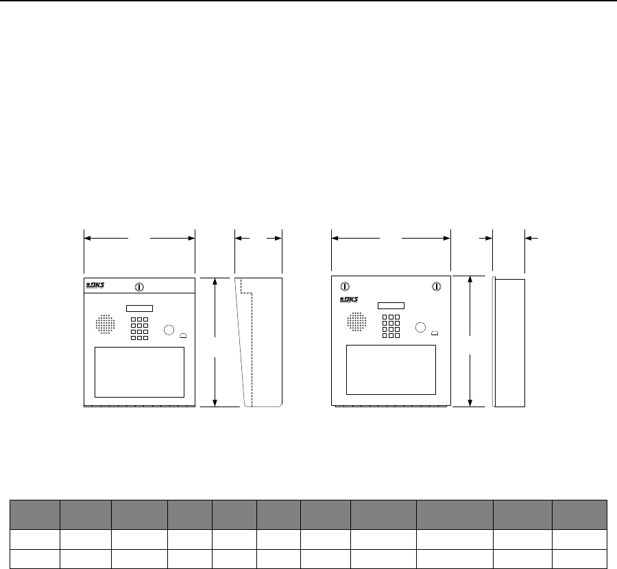
PRICE SCHEDULE A 2.0
Telephone Entry & Access Control Systems January 2019
Page 10 Specifications subject to change without notice.
1810 Telephone Entry System
Residential, Commercial
1810
• Hands free full duplex voice communication
• Programmable Directory Codes (1-4 digits)
• 16-digit dialing
• Includes 16 VAC power transformer
1810 AP (Access Plus) ONLY
• Control up to 8 entry points
• IP Addressable
• PC Programmable
• 2-Digit directory codes
• 20-digit dialing
• Includes 16 VAC power transformer
13.25
336.55 mm
13.00
4.75 3.2511.25
Surface Mount
1810 / 1810 AP Flush Mount
1810 / 1810 AP
12.00
285.75 mm 120.65 mm
330.20 mm
304.80 mm 82.55 mm
123
456
789
*0 #
1 2 3
4 5 6
78 9
*0 #
Model
Phone
Numbers
Directory
Names
Entry
Codes1
Device
Codes2
Relays
Auxiliary
Inputs3
Expansion4
PC
Programmable5
Temporary
Codes
Holiday
Schedules
1810 600 N/A 1000 0 2 1 No No 5 No
1810AP 27 N/A 50 100 2 2 6 Max Yes 10 Yes
1. Entry codes are four (4) digits only and are not the same as device codes. Entry codes grant access when entered on the entry system keypad (or
secondary keypad) only.
2. Device codes refer to any five (5) digit RS-485 device used to access an entry point, such as cards, transmitters or PINs (Personal Identification
Number). Five (5) digit device codes can also be used on the system keypad.
3. 1810 auxiliary input allows a switch closure to activate relay 2, or can be set to auto-dial a preprogrammed telephone number. 1810 AP uses a
standard RS-485 data input.
4. Six (6) additional entry points can be controlled via RS-485 card readers, AVID tag readers, RF receivers or digital keypads.
5. AP Programming software available for free download at doorking.com.
Page Rev 1/2/19

January 2019 PRICE SCHEDULE A 2.0
Telephone Entry & Access Control Systems
Specifications subject to change without notice. Page 11
1810 Telephone Entry System
Residential, Commercial
1810 Telephone Entry Systems
1810-080 Surface Mount ........................................... 1566.00
1810-084 Flush Mount ............................................... 1566.00
1810-095 Surface Mount AP (Access Plus) ................. 2050.00
1810-096 Flush Mount AP (Access Plus) .................... 2050.00
1810 Lobby Panels
1810-088 Surface Mount ........................................... 1216.00
1810-090 Flush Mount ............................................... 1206.00
Lobby panels can only be used with the 1816 or 1820 telephone
intercom system. They cannot be connected directly to telephone
service.
Service Connection Options
1800-081 Cellular Voice + Data1,2 ................................. 654.00
1801-080 Cellular Voice Only1,3 ................................... 434.00
1 - Cellular service plan required (provided by DoorKing).
2 - Use with 1810 AP model.
3 - Use with 1810 model.
Accessories
1803-150 Surface Mount Trim Ring Black .................... 236.00
1814-165 Flush Mount Kit Stainless Steel .................... 396.00
1814-152 Surface Mount Ring for Flush Units ............. 236.00
1701-080 20-Name Directory....................................... 156.00
1702-080 60-Name Directory....................................... 228.00
1710-080 200-Name Directory Surface Mount ............ 484.00
1710-081 200-Name Directory Flush Mount................ 484.00
1506-081 Secondary Keypad surface mount................ 444.00
1506-091 Secondary Keypad flush mount ................... 576.00
1720-080 LED Light Kit ................................................. 444.00
1804-193 External Speaker .......................................... 202.00
1801-008 Backup Battery 12-Volt .8 Ah ......................... 91.52
2600-584 Heater Kit ..................................................... 170.00
1812-145 CCTV Color Camera .................................... 1022.00
1807-012 Handset Kit (surface mount only) ..................... 422.00
1830-310 TTY Add-on Factory Installed ....................... 312.00
1830-315 TTY Add-on Kit ............................................. 348.00
1810 AP (ACCESS PLUS ONLY) Expansion Options
2354-010 Conversion Board ......................................... 180.00
1815-235 Conversion Board w/Enclosure .................... 316.00
Converts 26-bit Wiegand to RS-485. Requires 12-16 VDC power.
1812-020 12-VDC, 1A Transformer ................................ 51.62
1200-080 Transformer Box........................................... 234.00
1816-083 Intercom Phone Expansion......................... 1144.00
The 1816-083 expands the “No Phone Line” telephone intercom
interface on Access Plus systems from a single phone line up to 11
phone lines. The system can be further expanded to interface with up
to a maximum of 23 phone lines.
RS-485 Card Readers (ACCESS PLUS ONLY)
1815-332 DK Prox Reader ............................................ 432.00
1815-232 ID Tech Reader ............................................. 504.00
1815-233 AWID Reader ................................................ 516.00
1815-234 HID Reader ................................................... 916.00
RS-485 Keypads (ACCESS PLUS ONLY)
1513-081 Surface Mount.............................................. 542.00
1513-082 Flush Mount ................................................. 674.00
RS-485 RF Controls (ACCESS PLUS ONLY)
8053-080 MicroPlus Receiver ....................................... 218.00
Page Rev 1/2/19
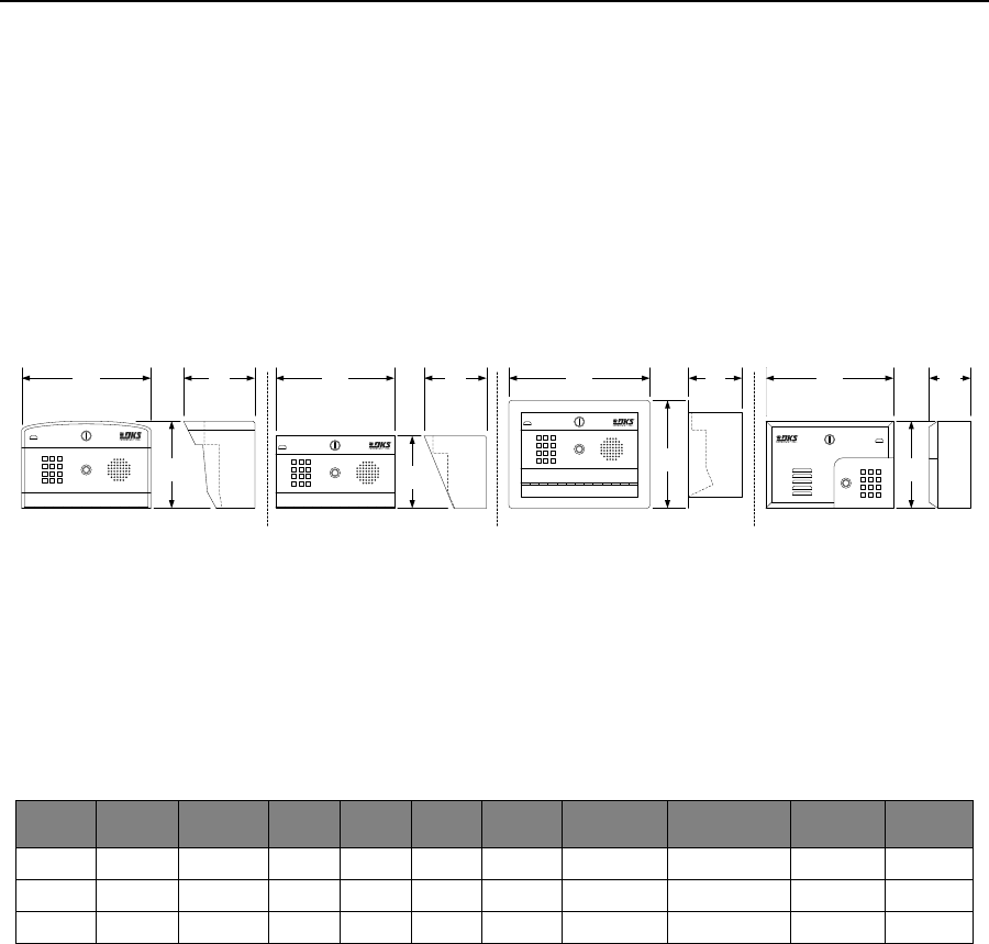
PRICE SCHEDULE A 2.0
Telephone Entry & Access Control Systems January 2019
Page 12 Specifications subject to change without notice.
1812 Telephone Entry System
Residential
1812 (Classic)
• 2-Digit directory codes
• 11-digit dialing
• Includes 24 VAC power transformer
• Call Forward Time Zones
• Do Not Disturb
• Analog Voice Circuit
1812 P (Plus) and 1812 AP (Access Plus)
• 2-Digit directory codes
• 20-digit dialing
• Includes 16 VAC power transformer
• Call Forward Time Zones
• Do Not Disturb Feature
• HD Digital Voice Circuit
7.38 6.13
9.13
5.256.00
Surface Mount Curved
1812 P / 1812 AP Surface Mount
1812 / 1812 P / 1812 AP
10.88 10.00 4.5011.88
7.38
10.75 3.50
187.5 mm
273.05 mm 88.9 mm114.3 MM
231.9 MM
123
456
789
*0 #
301.75 MM133.35 MM254.0 MM
155.7 MM
1 2 3
4 5 6
7 8 9
*0 #
152.4 MM
187.5 MM
1 2 3
4 5 6
7 8 9
*0 #
276.35 MM
1 2 3
4 5 6
7 8 9
*0 #
Flush Mount
1812 / 1812 P / 1812 AP Wall Mount
1812 / 1812 P / 1812 AP
Model
Phone
Numbers
Directory
Names
Entry
Codes1
Device
Codes2
Relays
Auxiliary
Inputs3
Expansion4
PC
Programmable5
Temporary
Codes
Holiday
Schedules
1812 3 N/A 50 0 2 1 No No 5 No
1812P 27 N/A 0 50 2 0 No No 10 No
1812AP 27 N/A 0 100 2 2 6 Max Yes 10 Yes
1. Entry codes are four (4) digits on the 1812. Entry codes grant access when entered on the entry system keypad (or secondary keypad) only.
2. Device codes refer to any five (5) digit RS-485 device used to access an entry point, such as cards, transmitters or PINs (Personal Identification
Number). Five (5) digit device codes can also be used as entry codes and are used on the system keypad.
3. 1810 auxiliary input allows a switch closure to activate relay 2, or can be set to auto-dial a preprogrammed telephone number. 1810 AP uses a
standard RS-485 data input.
4. Six (6) additional entry points can be controlled via RS-485 card readers, AVID tag readers, RF receivers or digital keypads.
5. AP Programming software available for free download at doorking.com.
Page Rev 1/2/19

January 2019 PRICE SCHEDULE A 2.0
Telephone Entry & Access Control Systems
Specifications subject to change without notice. Page 13
1812 Telephone Entry System
Residential
1812 Classic Systems
1812-081 Surface Mount ........................................... 1598.00
1812-097 Surface Mount w/Camera .......................... 2536.00
1812-087 Flush Mount ............................................... 1808.00
1812-088 Wall Mount ................................................ 1808.00
1812 Plus Systems
1812-095 Surface Mount Curved ............................... 1930.00
1812-089 Surface Mount ........................................... 1710.00
1812-098 Surface Mount w/Camera .......................... 2646.00
1812-091 Flush Mount ............................................... 1920.00
1812-093 Wall Mount ................................................ 1920.00
1812 Access Plus Systems
1812-096 Surface Mount Curved ............................... 2040.00
1812-090 Surface Mount ........................................... 1818.00
1812-099 Surface Mount w/Camera .......................... 2758.00
1812-092 Flush Mount ............................................... 2028.00
1812-094 Wall Mount ................................................ 2028.00
Service Connection Options
1800-081 Cellular Voice + Data1,2 ................................. 654.00
1801-080 Cellular Voice Only1,3 ................................... 434.00
1 - Cellular service plan required (provided by DoorKing).
2 - Use with 1812 AP model.
3 - Use with 1812 Classic and Plus models.
Accessories
1812-105 Stainless Steel Surface Mount Housing1 ....... 266.00
1506-081 Secondary Keypad surface mount................ 444.00
1506-091 Secondary Keypad flush mount ................... 576.00
2600-588 Heater Kit (for surface mount units) ................. 238.00
2600-582 Heater Kit (for flush mount units) ....................... 52.98
1812-145 CCTV Color Camera .................................... 1022.00
1812-074 Conversion Kit2 ........................................... 1776.00
1 – Replaces the black steel housing.
2 - Upgrades older 1812 units to an 1812 Access Plus unit.
1830-310 TTY Add-on Factory Installed ....................... 312.00
1830-315 TTY Add-on Kit ............................................. 348.00
1812 AP (ACCESS PLUS ONLY) Expansion Options
2354-010 Conversion Board ......................................... 180.00
1815-235 Conversion Board w/Enclosure .................... 316.00
Converts 26-bit Wiegand to RS-485. Requires 12-16 VDC power.
1812-020 12-VDC, 1A Transformer ................................ 51.62
1200-080 Transformer Box........................................... 234.00
1816-083 Intercom Phone Expansion......................... 1144.00
The 1816-083 expands the “No Phone Line” telephone intercom
interface on Access Plus systems from a single phone line up to 11
phone lines. The system can be further expanded to interface with up
to a maximum of 23 phone lines.
RS-485 Card Readers (ACCESS PLUS ONLY)
1815-332 DK Prox Reader ............................................ 432.00
1815-232 ID Tech Reader ............................................. 504.00
1815-233 AWID Reader ................................................ 516.00
1815-234 HID Reader ................................................... 916.00
RS-485 Keypads (ACCESS PLUS ONLY)
1513-081 Surface Mount.............................................. 542.00
1513-082 Flush Mount ................................................. 674.00
RS-485 RF Controls (ACCESS PLUS ONLY)
8053-080 MicroPlus Receiver ....................................... 218.00
Page Rev 1/2/19
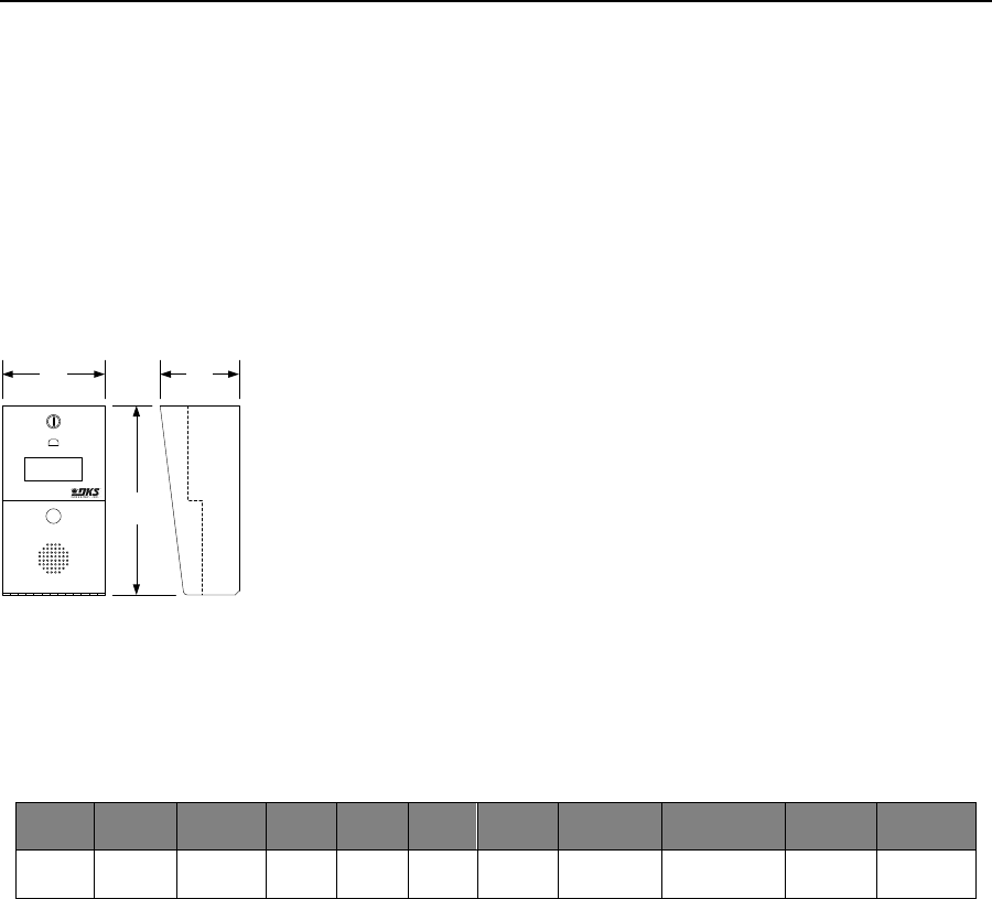
PRICE SCHEDULE A 2.0
Telephone Entry & Access Control Systems January 2019
Page 14 Specifications subject to change without notice.
1819 Information Telephone System
Commercial
1819
• Full duplex voice communication
• Stores a single phone number
• 10 and 11 digit dialing
• Call button
6.50
12.00
5.00
Call
INFORMATION
I
N
F
O
R
M
A
T
I
O
N
304.80 mm
165.10 mm 127.00 mm
Surface Mount
Model
Phone
Numbers
Directory
Entry
Codes
Device
Codes
Relays
Auxiliary
Inputs
Expansion4
PC
Programmable
Elevator
Control
Transaction
Buffer
1819 1 N/A 0 0 1 0 0 No No No
1. The 1819 is designed as an information phone only. Pressing the CALL button causes the system to dial to a preprogrammed telephone number.
Page Rev 1/2/19

January 2019 PRICE SCHEDULE A 2.0
Telephone Entry & Access Control Systems
Specifications subject to change without notice. Page 15
1819 Information Telephone System
Commercial
1819 Telephone Entry System
1819-080 Surface Mount ........................................... 1422.00
Service Connection Options
1801-080 Cellular Voice1 .............................................. 434.00
1 – DKS Cellular subscription required.
Accessories
1801-008 Backup Battery 12-Volt .8 Ah ......................... 91.52
2600-588 Heater Kit ..................................................... 238.00
1812-145 CCTV Color Camera .................................... 1022.00
1802-111 Post Mount Adapter Plate1 .......................... 166.00
1 - Required if mounting the unit to a goose neck post.
Page Rev 1/2/19
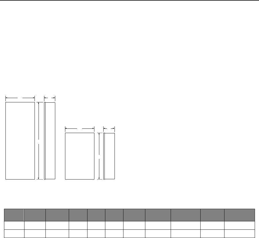
PRICE SCHEDULE A 2.0
Telephone Entry & Access Control Systems January 2019
Page 16 Specifications subject to change without notice.
1816 / 1820 Telephone Intercom Systems
Commercial
1816
• Full duplex voice communication
• Interfaces with up to 1200 phone lines
• Tennant C.O. phone service not required
• Programmable directory codes
• Lobby panel / Doorman caller ID
• Built-in call waiting
• Do Not Disturb feature
1820
• Full duplex voice communication
• Interfaces with up to 1200 phone lines
• Tennant C.O. phone service not required
• Programmable directory codes
• Resident Call Down feature
• Resident programmable Call Forward feature
• Resident programmable Do-Not-Disturb Feature
5.0013.25
Large Cabinet
336.55 mm 127.00 mm
35.25
895.35 mm
13.25 5.00
21.25
539.75 mm
Standard Cabinet
127.00 mm336.55 mm
Model
Phone
Numbers
Directory
Names
Entry
Codes1
Caller
ID
Relays
Doorman
Phone
Resident
Call-Down2
Resident
Features3
Call Out
Numbers
Directory
Codes
1816 1200 N/A 1200 Yes 1 Yes No No 10 Programmable
1820 1200 N/A 1200 Yes 1 Yes Yes Yes 10 Programmable
1. Entry codes are four (4) digits. Entry codes grant access when entered on the entry system keypad (or secondary keypad) only.
2. The resident call-down feature allows the resident to contact the doorman directly from their telephone.
3. Resident programmable features include: Call Waiting; Do-Not-Disturb; Call Forwarding.
Page Rev 1/2/19

January 2019 PRICE SCHEDULE A 2.0
Telephone Entry & Access Control Systems
Specifications subject to change without notice. Page 17
1816 / 1820 Telephone Intercom Systems
Commercial
1816 Systems
Step 1: Main Control Cabinet
1816-080 Houses 13 Relay Boards (156 lines)............ 2216.00
1816-082 Houses 5 Relay Boards (60 lines) ............... 1954.00
Main control cabinets do not include relay boards.
Step 2: Relay Boards
1982-010
1 – 13 Boards ............................................................... 712.00
14 – 29 Boards ............................................................. 672.00
30 + Boards .................................................................. 632.00
One (1) relay board is required for every 12 phone lines to be
interfaced.
Step 3: Decoder Board (if required)
1881-010 Decoder Board ............................................. 326.00
Decoder board(s) are required if the system expands beyond five (5)
relay boards. One (1) decoder board is required for every eight (8)
relay boards beyond the first five (5) relay boards.
Step 4: Auxiliary Cabinet (if required)
1816-081 Auxiliary Cabinet .......................................... 652.00
Holds up to 16 relay boards and two (2) decoder boards.
Step 5: Phone Blocks and Cables
2370-010 RJ71C Phone Block ....................................... 286.00
One (1) RJ71C is required for each relay board in the system.
1882-042 Connecting Cable ......................................... 144.00
One (1) connecting cable is required for each relay board in the system.
1882-044 Connecting Cable Special Length .............. 5.20 / ft.
Add cost per foot to 1882-042.
Step 6: Lobby Panels
Select lobby panels from the 1802, 1803, 1808, 1810 series
pages.
1820 Systems
Step 1: Main Control Cabinet
1820-080 Houses 9 Relay Boards (108 lines) .............. 2216.00
1820-082 Houses 4 Relay Boards (48 lines) ................ 1954.00
Main control cabinets do not include relay boards.
Step 2: Line Interface Boards
1884-010 .................................................................... 1542.00
One (1) relay board is required for every 12 phone lines to be
interfaced.
Step 3: Power Supply Boards (if required)
1886-010 ...................................................................... 260.00
Only required if more than 21 line interface boards are used; then one
(1) required for every 21 line interface boards in the system thereafter.
1508-060 ........................................................................ 57.80
One (1) required for each 1886-010 power supply board.
Step 4: Auxiliary Cabinet (if required)
1820-081 Large Auxiliary Cabinet ................................. 652.00
Holds up to 12 line interface boards and one (1) power supply board.
1820-083 ...................................................................... 396.00
Holds up to eight (8) line interface boards or seven (7) line interface
boards and one (1) power supply board.
Step 5: Phone Blocks and Cables
2370-010 RJ71C Phone Block ....................................... 286.00
One (1) RJ71C is required for each relay board in the system.
1882-042 Connecting Cable ......................................... 144.00
One (1) connecting cable is required for each relay board in the system.
1882-044 Connecting Cable Special Length ............... 5.20 / ft.
Add cost per foot to 1882-042.
Step 6: Lobby Panels
Select lobby panels from the 1802, 1803, 1808, 1810 series
pages.
Page Rev 1/2/19
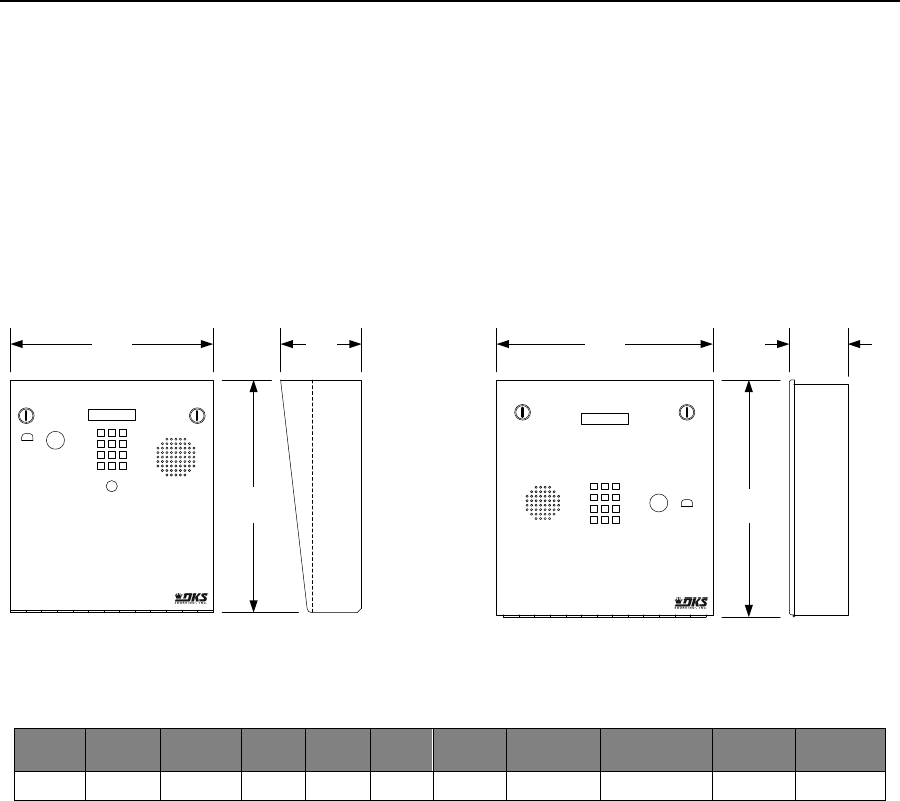
PRICE SCHEDULE A 2.0
Telephone Entry & Access Control Systems January 2019
Page 18 Specifications subject to change without notice.
1833 Telephone Entry System – 80 Series
Residential, Commercial
1833
• Full duplex voice communication
• Stores up to 3000 phone numbers
• 255 area codes
• Programmable directory codes
• 10 and 11 digit dialing
• Built-in clock/calendar
• Three (3) built-in relays
• Two (2) 26-bit wiegand inputs
• Expandable to control up to 24 entrances
• 31 security (permission) levels
• 32 holiday schedules
• True anti-pass back features
Model
Phone
Numbers
Directory
Entry
Codes1
Device
Codes2
Relays
Auxiliary
Inputs3
Expansion4
PC
Programmable5
Elevator
Control
Transaction
Buffer
1833 3000 N/A 3000 8000 3 2 48 Max Yes Yes 8000
1. Entry codes are four (4) digits only and are not the same as device codes. Entry codes grant access when entered on the entry system keypad (or
secondary keypad) only.
2. Device codes refer to any five (5) digit 26-bit wiegand device used to access an entry point, such as cards, transmitters or PINs (Personal
Identification Number). Five (5) digit device codes can also be used on the system keypad.
3. 1833 has two 26-bit wiegand inputs.
4. Up to 48 additional entry points can be controlled via card readers, AVID tag readers, RF receivers or digital keypads using tracker expansion
boards.
5. Programming and transaction analysis software available for free download at doorking.com.
Page Rev 1/2/19
13.00
1 2 3
4 5 6
789
*0 #
4.50
13.25
11.25 12.00
Surface Mount
3.25
Flush Mount
285.75 mm
330.20 mm 336.55 mm
304.80 mm 82.55 mm
123
456
789
*0#
114.30 mm

January 2019 PRICE SCHEDULE A 2.0
Telephone Entry & Access Control Systems
Specifications subject to change without notice. Page 19
1833 Telephone Entry Systems – 80 Series
Residential, Commercial
1833 Telephone Entry System
1833-080 Surface Mount ........................................... 3406.00
1833-084 Flush Mount ............................................... 3406.00
Service Connection Options
1800-080 Cellular Voice + Data1 ................................... 654.00
2334-080 VoIP - TCP/IP Control Box3,5.......................... 522.00
1815-568 VoIP Adapter2,4 ............................................. 128.00
1830-186 Plug & Play3,4 (Plug & Play) ........................... 228.00
1830-185 Network Adapter (Manual Setup) ................ 228.00
1 – DKS Cellular subscription required.
2 – DKS VoIP subscription required.
3 – DKS VoIP or Data over IP subscription required.
4 – 1815-568 is required for voice, 1830-186 or 1830-185 is required
for data
5 – Combines the 1815-568 and 1830-186 into a common housing with
built-in ethernet switch.
Programming Only Connection Options
1508-055 RS232 to RS422 Conversion Kit .................. 1264.00
1815-037 USB to RS232 Adapter .................................. 180.00
1818-040 RS232 Connecting Cable 6-ft (1.8m) .............. 48.16
Accessories
1803-150 Surface Mount Trim Ring Black .................... 236.00
1814-165 Flush Mount Kit Stainless Steel .................... 396.00
1814-152 Surface Mount Ring for Flush Units.............. 236.00
1701-080 20-Name Directory ....................................... 156.00
1702-080 60-Name Directory ....................................... 228.00
1710-080 Large Directory Surface Mount .................... 484.00
1710-081 Large Directory Flush Mount ........................ 484.00
1506-081 Secondary Keypad surface mount ................ 444.00
1506-091 Secondary Keypad flush mount .................... 576.00
1720-080 LED Light Kit ................................................. 444.00
1804-193 External Speaker .......................................... 202.00
1801-008 Backup Battery 12-Volt .8 Ah ......................... 91.52
2600-584 Heater Kit ..................................................... 170.00
1812-145 Camera ....................................................... 1022.00
1807-012 Handset Kit (surface mount only) ..................... 422.00
1830-315 TTY Add-on kit .............................................. 348.00
Expansion Options
2358-010 Tracker Expansion Board .............................. 516.00
2351-080 Sgl Box1 (1 board max) .................................... 698.00
2351-084 Sgl Box1 + 1489-080 2.4 GHz RF Module .... 1142.00
2351-085 Sgl Box1 + 1490-080 900 MHz RF Module .. 1142.00
2351-082 QUAD Box1 Pre-wired (4 boards max) ........... 1206.00
1 – Includes one (1) 2358-010 board and 16V, 40 VA transformer.
Expansion Option Wireless Kits
2361-080 Base Board Kit1 2.4 GHz ................................ 576.00
2333-080 Base Board Kit1 900 MHz .............................. 620.00
1489-080 Expansion Board Kit2 2.4 GHZ ....................... 304.00
1470-080 Expansion Board Kit2 900 MHZ ..................... 368.00
2364-080 Single channel repeater 2.4 GHz .................. 306.00
2372-080 Dual channel repeater 2.4 GHz .................... 440.00
2332-080 Dual channel repeater 900 MHz................... 578.00
1 - One (1) base board kit is installed in the 1833 controller.
2 – Expansion board kit(s) are installed on each 2358 tracker board.
1514-075 2.4 GHz antenna extension kit ....................... 60.18
1514-079 900 MHz antenna extension kit ..................... 60.18
8064-046 Coax cable extension 13-ft (3.9m) .................. 49.38
1514-004 Disk antenna 2.4 GHz ..................................... 36.12
1514-003 Six inch (152mm) antenna 2.4 GHz ................ 54.60
1514-028 Disk antenna 900 MHz ................................... 33.60
1514-019 Six inch (152mm) antenna 900 MHz .............. 33.60
1514-130 Wireless range test kit 2.4 GHz .................... 838.00
Elevator Control
2348-0401 Elevator control board + hardware ........... 2216.00
2348-0802 Lockable enclosure ................................... 2868.00
2348-0813 Lockable enclosure large ........................... 3130.00
1 – Includes board and mounting hardware.
2 – Includes one (1) 2348-010 board. Room for two (2) boards’ total.
3 – Includes one (1) 2340-010 board. Room for four (4) boards’ total.
Page Rev 1/2/19
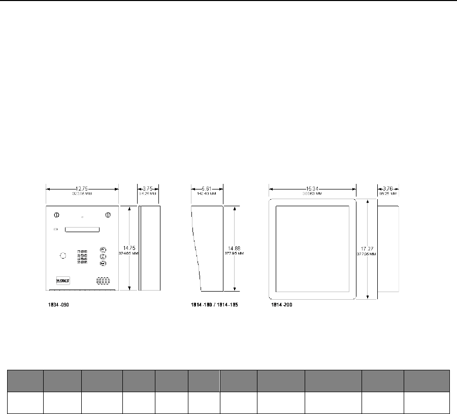
PRICE SCHEDULE A 2.0
Telephone Entry & Access Control Systems January 2019
Page 20 Specifications subject to change without notice.
1834 Telephone Entry System – 90 Series
Residential, Commercial
1834
• Larger cabinet, one design
• Dual locks, double weather seal
• Space for card reader, IP camera, TCP-IP adapter
• Optional 10 ga. hood, stainless steel or black
• Stainless steel flush kit
Model
1
Phone
Numbers
Directory
Entry
Codes2
Device
Codes3
Relays
Auxiliary
Inputs4
Expansion
PC
Programmable5
Elevator
Control
Transaction
Buffer
1834 3000 1-Line
Electronic 3000 0 2 0 No Yes No 8000
1. Card reader mounting will accommodate the following card readers only: 1815-302 (DK Prox), 1815-380 (HID), 1815-215 (ID-Teck). Note that the
1834 does not have inputs for the card reader. Any card reader installed in the 1834 will have to be connected to another access controller. See
1835 if a built-in card reader is desired.
2. Entry codes are four (4) digits only and are not the same as device codes. Entry codes grant access when entered on the entry system keypad (or
secondary keypad) only.
3. Device codes refer to any five (5) digit 26-bit wiegand device used to access an entry point, such as cards, transmitters or PINs (Personal
Identification Number). Five (5) digit device codes can also be used on the system keypad.
4. 1834 does not have any 26-bit wiegand inputs.
5. Programming and transaction analysis software available for free download at doorking.com.
• Full duplex voice communication
• 255 area codes
• Programmable directory codes
• 10 and 11 digit dialing
• Eight (8) hold open time zones
Page Rev 1/2/19

January 2019 PRICE SCHEDULE A 2.0
Telephone Entry & Access Control Systems
Specifications subject to change without notice. Page 21
1834 Telephone Entry Systems – 90 Series
Residential, Commercial
1834 Telephone Entry System
1834-090 .................................................................... 3118.00
Service Connection Options
1800-080 Cellular Voice + Data1 ................................... 654.00
2334-080 VoIP - TCP/IP Control Box3,5.......................... 522.00
1815-568 VoIP Adapter2,4 ............................................. 128.00
1830-186 Plug & Play3,4 (Plug & Play) ........................... 228.00
1830-185 Network Adapter (Manual Setup) ................ 228.00
1 – DKS Cellular subscription required.
2 – DKS VoIP subscription required.
3 – DKS VoIP or Data over IP subscription required.
4 – 1815-568 is required for voice, 1830-186 or 1830-185 is required
for data
5 – Combines the 1815-568 and 1830-186 into a common housing with
built-in ethernet switch.
Programming Only Connection Options
1508-055 RS232 to RS422 Conversion Kit .................. 1264.00
1815-037 USB to RS232 Adapter .................................. 180.00
1818-040 RS232 Connecting Cable 6-ft (1.8m) .............. 48.16
Accessories
1814-180 Stainless Steel Hood (10 ga) ......................... 430.00
1814-185 Black Hood (10 ga) ....................................... 214.00
1814-200 Flush Kit (Rough-in box + trim ring) .............. 606.00
1506-081 Secondary Keypad surface mount ................ 444.00
1506-091 Secondary Keypad flush mount .................... 576.00
1720-080 LED Light Kit ................................................. 444.00
1804-193 External Speaker .......................................... 202.00
1801-008 Backup Battery 12-Volt .8 Ah ......................... 91.52
2600-584 Heater Kit ..................................................... 170.00
1812-147 Camera ....................................................... 1022.00
1807-012 Handset Kit (surface mount only) ..................... 422.00
1830-315 TTY Add-on kit .............................................. 348.00
Page Rev 1/2/19
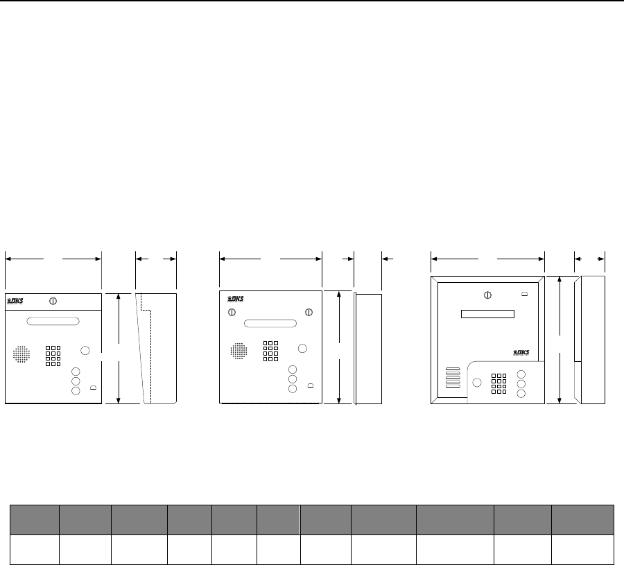
PRICE SCHEDULE A 2.0
Telephone Entry & Access Control Systems January 2019
Page 22 Specifications subject to change without notice.
1834 Telephone Entry System – 80 Series
Residential, Commercial
1834
• Full duplex voice communication
• Stores up to 3000 phone numbers
• 255 area codes
• Programmable directory codes
Model
Phone
Numbers
Directory
Entry
Codes1
Device
Codes2
Relays
Auxiliary
Inputs3
Expansion
PC
Programmable4
Elevator
Control
Transaction
Buffer
1834 3000 1-Line
Electronic 3000 0 2 0 No Yes No 8000
1. Entry codes are four (4) digits only and are not the same as device codes. Entry codes grant access when entered on the entry system keypad (or
secondary keypad) only.
2. Device codes refer to any five (5) digit 26-bit wiegand device used to access an entry point, such as cards, transmitters or PINs (Personal
Identification Number). Five (5) digit device codes can also be used on the system keypad.
3. 1834 does not have any 26-bit wiegand inputs.
4. Programming and transaction analysis software available for free download at doorking.com.
• 10 and 11 digit dialing
• Two (2) built-in relays
• Eight (8) hold open time zones
• Built-in clock/calendar
15.00
381.00 mm
13.25
336.55 mm
13.00
4.75 3.25 3.5011.25
Surface Mount Flush Mount
123
456
789
*0 #
A
Z
Call
12.00 13.25
Wall Mount
A
Z
Call
123
456
789
*0 #
123
4 5 6
789
*0 #
A
Z
Call
285.75 mm 120.65 mm
330.20 mm
304.80 mm 82.55 mm 336.55 mm 88.90 mm
Page Rev 1/2/19

January 2019 PRICE SCHEDULE A 2.0
Telephone Entry & Access Control Systems
Specifications subject to change without notice. Page 23
1834 Telephone Entry Systems – 80 Series
Residential, Commercial
1834 Telephone Entry System
1834-080 Surface Mount ........................................... 2852.00
1834-084 Flush Mount ............................................... 2852.00
1834-089 Wall Mount ................................................ 3118.00
Service Connection Options
1800-080 Cellular Voice + Data1 ................................... 654.00
2334-080 VoIP - TCP/IP Control Box3,5.......................... 522.00
1815-568 VoIP Adapter2,4 ............................................. 128.00
1830-186 Plug & Play3,4 (Plug & Play) ........................... 228.00
1830-185 Network Adapter (Manual Setup) ................ 228.00
1 – DKS Cellular subscription required.
2 – DKS VoIP subscription required.
3 – DKS VoIP or Data over IP subscription required.
4 – 1815-568 is required for voice, 1830-186 or 1830-185 is required
for data
5 – Combines the 1815-568 and 1830-186 into a common housing with
built-in ethernet switch.
Programming Only Connection Options
1508-055 RS232 to RS422 Conversion Kit .................. 1264.00
1815-037 USB to RS232 Adapter .................................. 180.00
1818-040 RS232 Connecting Cable 6-ft (1.8m) .............. 48.16
Accessories
1803-150 Surface Mount Trim Ring Black .................... 236.00
1814-165 Flush Mount Kit Stainless Steel .................... 396.00
1814-152 Surface Mount Ring for Flush Units.............. 236.00
1506-081 Secondary Keypad surface mount ................ 444.00
1506-091 Secondary Keypad flush mount .................... 576.00
1720-080 LED Light Kit ................................................. 444.00
1804-193 External Speaker .......................................... 202.00
1801-008 Backup Battery 12-Volt .8 Ah ......................... 91.52
2600-584 Heater Kit ..................................................... 170.00
1812-145 Camera (use with flush & wall mount) ............. 1022.00
1812-147 Camera (use with surface mount) ................... 1022.00
1807-012 Handset Kit (surface mount only) ..................... 422.00
1830-315 TTY Add-on kit .............................................. 348.00
Page Rev 1/2/19
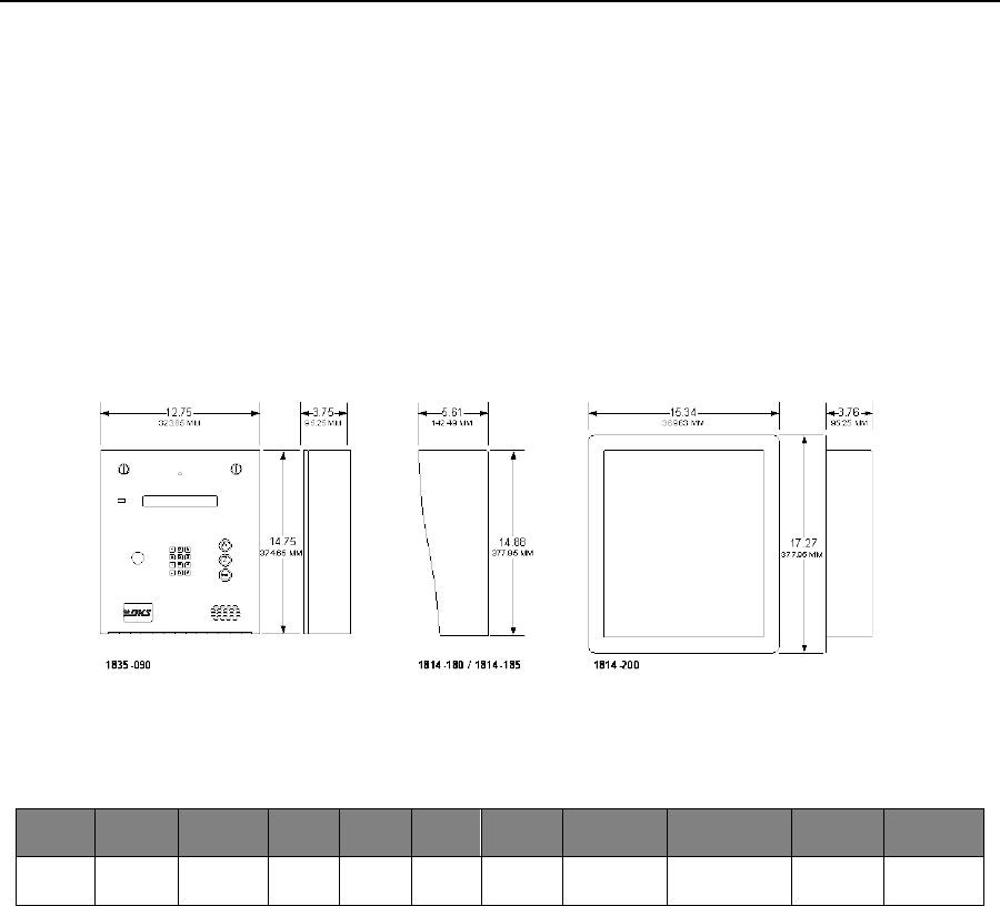
PRICE SCHEDULE A 2.0
Telephone Entry & Access Control Systems January 2019
Page 24 Specifications subject to change without notice.
1835 Telephone Entry System – 90 Series
Residential, Commercial
1835
• Larger cabinet, one design
• Dual locks, double weather seal
• Space for card reader, IP camera, TCP-IP adapter
• Optional 10 ga. hood, stainless steel or black
• Optional stainless steel flush kit
• 31 security (permission) levels
• 32 holiday schedules
• True anti-pass back features
• 10 and 11 digit dialing
• Eight (8) hold open time zones
Page Rev 1/2/19
Model1
Phone
Numbers
Directory
Entry
Codes2
Device
Codes3
Relays
Auxiliary
Inputs4
Expansion5
PC
Programmable6
Elevator
Control
Transaction
Buffer
1835 3000 1-Line
Electronic 3000 8000 3 2 48 Max Yes Yes 8000
1. Card reader mounting will accommodate the following card readers only: 1815-302 (DK Prox), 1815-380 (HID), 1815-215 (ID-Teck).
2. Entry codes are four (4) digits only and are not the same as device codes. Entry codes grant access when entered on the entry system keypad (or
secondary keypad) only.
3. Device codes refer to any five (5) digit 26-bit wiegand device used to access an entry point, such as cards, transmitters or PINs (Personal
Identification Number). Five (5) digit device codes can also be used on the system keypad.
4. 1835 has two 26-bit wiegand inputs.
5. Up to 48 additional entry points can be controlled via card readers, AVID tag readers, RF receivers or digital keypads using tracker expansion
boards.
6. Programming and transaction analysis software available for free download at doorking.com.

January 2019 PRICE SCHEDULE A 2.0
Telephone Entry & Access Control Systems
Specifications subject to change without notice. Page 25
1835 Telephone Entry Systems – 90 Series
Residential, Commercial
1835 Telephone Entry System
1835-090 .................................................................... 4434.00
Service Connection Options
1800-080 Cellular Voice + Data1 ................................... 654.00
2334-080 VoIP - TCP/IP Control Box3,5.......................... 522.00
1815-568 VoIP Adapter2,4 ............................................. 128.00
1830-186 Plug & Play3,4 (Plug & Play) ........................... 228.00
1830-185 Network Adapter (Manual Setup) ................ 228.00
1 – DKS Cellular subscription required.
2 – DKS VoIP subscription required.
3 – DKS VoIP or Data over IP subscription required.
4 – 1815-568 is required for voice, 1830-186 or 1830-185 is required
for data
5 – Combines the 1815-568 and 1830-186 into a common housing with
built-in ethernet switch.
Programming Only Connection Options
1508-055 RS232 to RS422 Conversion Kit .................. 1264.00
1815-037 USB to RS232 Adapter .................................. 180.00
1818-040 RS232 Connecting Cable 6-ft (1.8m) .............. 48.16
Accessories
1814-180 Stainless Steel Hood (10 ga) ......................... 430.00
1814-185 Black Hood (10 ga) ....................................... 214.00
1814-200 Flush Kit (Rough-in box + trim ring) .............. 606.00
1506-081 Secondary Keypad surface mount ................ 444.00
1506-091 Secondary Keypad flush mount .................... 576.00
1720-080 LED Light Kit ................................................. 444.00
1804-193 External Speaker .......................................... 202.00
1801-008 Backup Battery 12-Volt .8 Ah ......................... 91.52
2600-584 Heater Kit ..................................................... 170.00
1812-145 Camera ....................................................... 1022.00
1807-012 Handset Kit (surface mount only) ..................... 422.00
1830-315 TTY Add-on kit .............................................. 348.00
Expansion Options
2358-010 Tracker Expansion Board .............................. 516.00
2351-080 Sgl Box1 (1 board max) .................................... 698.00
2351-084 Sgl Box1 + 1489-080 2.4 GHz RF Module .... 1142.00
2351-085 Sgl Box1 + 1490-080 900 MHz RF Module .. 1142.00
2351-082 QUAD Box1 Pre-wired (4 boards max) ........... 1206.00
1 – Includes one (1) 2358-010 board and 16V, 40 VA transformer.
Expansion Option Wireless Kits
2361-080 Base Board Kit1 2.4 GHz ................................ 576.00
2333-080 Base Board Kit1 900 MHz .............................. 620.00
1489-080 Expansion Board Kit2 2.4 GHZ ....................... 304.00
1470-080 Expansion Board Kit2 900 MHZ ..................... 368.00
2364-080 Single channel repeater 2.4 GHz .................. 306.00
2372-080 Dual channel repeater 2.4 GHz .................... 440.00
2332-080 Dual channel repeater 900 MHz................... 578.00
1 - One (1) base board kit is installed in the 1833 controller.
2 – Expansion board kit(s) are installed on each 2358 tracker board.
1514-075 2.4 GHz antenna extension kit ....................... 60.18
1514-079 900 MHz antenna extension kit ..................... 60.18
8064-046 Coax cable extension 13-ft (3.9m) .................. 49.38
1514-004 Disk antenna 2.4 GHz ..................................... 36.12
1514-003 Six inch (152mm) antenna 2.4 GHz ................ 54.60
1514-028 Disk antenna 900 MHz ................................... 33.60
1514-019 Six inch (152mm) antenna 900 MHz .............. 33.60
1514-130 Wireless range test kit 2.4 GHz .................... 838.00
Elevator Control
2348-0401 Elevator control board + hardware ........... 2216.00
2348-0802 Lockable enclosure ................................... 2868.00
2348-0813 Lockable enclosure large ........................... 3130.00
1 – Includes board and mounting hardware.
2 – Includes one (1) 2348-010 board. Room for two (2) boards’ total.
3 – Includes one (1) 2340-010 board. Room for four (4) boards’ total.
Page Rev 1/2/19
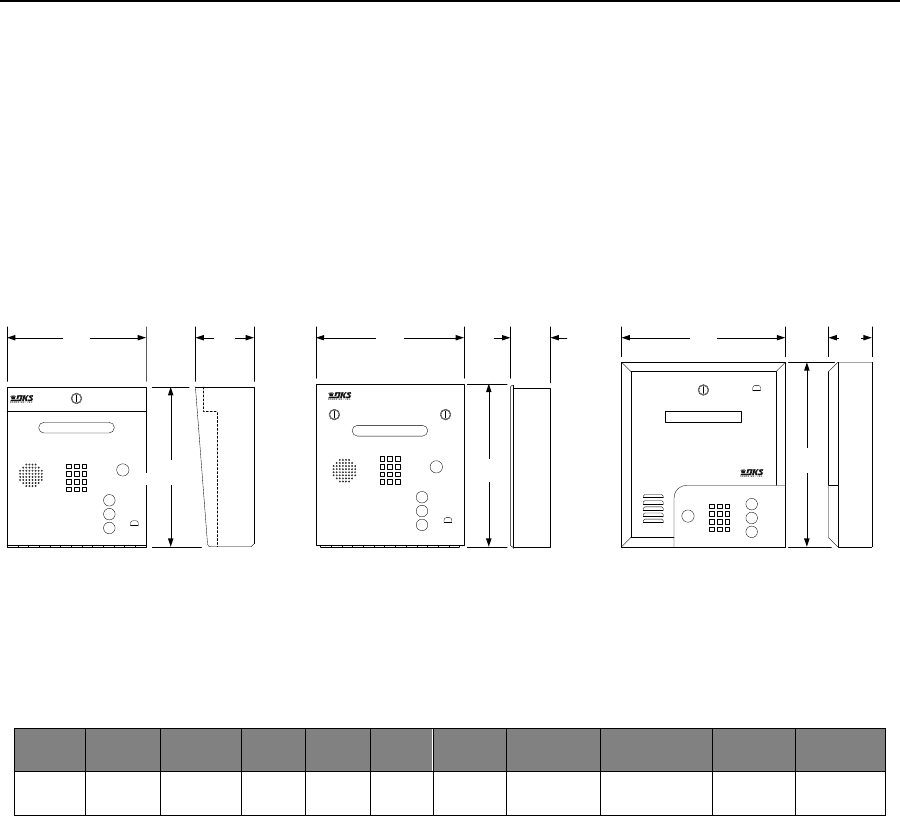
PRICE SCHEDULE A 2.0
Telephone Entry & Access Control Systems January 2019
Page 26 Specifications subject to change without notice.
1835 Telephone Entry System – 80 Series
Residential, Commercial
1835
• Full duplex voice communication
• Stores up to 3000 phone numbers
• 255 area codes
• Programmable directory codes
• 10 and 11 digit dialing
• Built-in clock/calendar
• Three (3) built-in relays
• Two (2) 26-bit wiegand inputs
• Expandable to control up to 24 entrances
• 31 security (permission) levels
• 32 holiday schedules
• True anti-pass back features
15.00
381.00 mm
13.25
336.55 mm
13.00
4.75 3.25 3.5011.25
Surface Mount Flush Mount
123
456
789
*0 #
A
Z
Call
12.00 13.25
Wall Mount
A
Z
Call
123
456
789
*0 #
123
4 5 6
7 8 9
*0 #
A
Z
Call
285.75 mm 120.65 mm
330.20 mm
304.80 mm 82.55 mm 336.55 mm 88.90 mm
Model
Phone
Numbers
Directory
Entry
Codes1
Device
Codes2
Relays
Auxiliary
Inputs3
Expansion4
PC
Programmable5
Elevator
Control
Transaction
Buffer
1835 3000 1-Line
Electronic 3000 8000 3 2 48 Max Yes Yes 8000
1. Entry codes are four (4) digits only and are not the same as device codes. Entry codes grant access when entered on the entry system keypad (or
secondary keypad) only.
2. Device codes refer to any five (5) digit 26-bit wiegand device used to access an entry point, such as cards, transmitters or PINs (Personal
Identification Number). Five (5) digit device codes can also be used on the system keypad.
3. 1835 has two 26-bit wiegand inputs.
4. Up to 48 additional entry points can be controlled via card readers, AVID tag readers, RF receivers or digital keypads using tracker expansion
boards.
5. Programming and transaction analysis software available for free download at doorking.com.
Page Rev 1/2/19

January 2019 PRICE SCHEDULE A 2.0
Telephone Entry & Access Control Systems
Specifications subject to change without notice. Page 27
1835 Telephone Entry Systems – 80 Series
Residential, Commercial
1835 Telephone Entry System
1835-080 Surface Mount ........................................... 4180.00
1835-084 Flush Mount ............................................... 4180.00
1835-089 Wall Mount ................................................ 4434.00
Service Connection Options
1800-080 Cellular Voice + Data1 ................................... 654.00
2334-080 VoIP - TCP/IP Control Box3,5.......................... 522.00
1815-568 VoIP Adapter2,4 ............................................. 128.00
1830-186 Plug & Play3,4 (Plug & Play) ........................... 228.00
1830-185 Network Adapter (Manual Setup) ................ 228.00
1 – DKS Cellular subscription required.
2 – DKS VoIP subscription required.
3 – DKS VoIP or Data over IP subscription required.
4 – 1815-568 is required for voice, 1830-186 or 1830-185 is required
for data
5 – Combines the 1815-568 and 1830-186 into a common housing with
built-in ethernet switch.
Programming Only Connection Options
1508-055 RS232 to RS422 Conversion Kit .................. 1264.00
1815-037 USB to RS232 Adapter .................................. 180.00
1818-040 RS232 Connecting Cable 6-ft (1.8m) .............. 48.16
Accessories
1803-150 Surface Mount Trim Ring Black .................... 236.00
1814-165 Flush Mount Kit Stainless Steel .................... 396.00
1814-152 Surface Mount Ring for Flush Units.............. 236.00
1506-081 Secondary Keypad surface mount ................ 444.00
1506-091 Secondary Keypad flush mount .................... 576.00
1720-080 LED Light Kit ................................................. 444.00
1804-193 External Speaker .......................................... 202.00
1801-008 Backup Battery 12-Volt .8 Ah ......................... 91.52
2600-584 Heater Kit ..................................................... 170.00
1812-145 Camera (use with flush & wall mount) ............. 1022.00
1812-147 Camera (use with surface mount) ................... 1022.00
1807-012 Handset Kit (surface mount only) ..................... 422.00
1830-315 TTY Add-on kit .............................................. 348.00
Expansion Options
2358-010 Tracker Expansion Board .............................. 516.00
2351-080 Sgl Box1 (1 board max) .................................... 698.00
2351-084 Sgl Box1 + 1489-080 2.4 GHz RF Module .... 1142.00
2351-085 Sgl Box1 + 1490-080 900 MHz RF Module .. 1142.00
2351-082 QUAD Box1 Pre-wired (4 boards max) ........... 1206.00
1 – Includes one (1) 2358-010 board and 16V, 40 VA transformer.
Expansion Option Wireless Kits
2361-080 Base Board Kit1 2.4 GHz ................................ 576.00
2333-080 Base Board Kit1 900 MHz .............................. 620.00
1489-080 Expansion Board Kit2 2.4 GHZ ....................... 304.00
1470-080 Expansion Board Kit2 900 MHZ ..................... 368.00
2364-080 Single channel repeater 2.4 GHz .................. 306.00
2372-080 Dual channel repeater 2.4 GHz .................... 440.00
2332-080 Dual channel repeater 900 MHz................... 578.00
1 - One (1) base board kit is installed in the 1833 controller.
2 – Expansion board kit(s) are installed on each 2358 tracker board.
1514-075 2.4 GHz antenna extension kit ....................... 60.18
1514-079 900 MHz antenna extension kit ..................... 60.18
8064-046 Coax cable extension 13-ft (3.9m) .................. 49.38
1514-004 Disk antenna 2.4 GHz ..................................... 36.12
1514-003 Six inch (152mm) antenna 2.4 GHz ................ 54.60
1514-028 Disk antenna 900 MHz ................................... 33.60
1514-019 Six inch (152mm) antenna 900 MHz .............. 33.60
1514-130 Wireless range test kit 2.4 GHz .................... 838.00
Elevator Control
2348-0401 Elevator control board + hardware ........... 2216.00
2348-0802 Lockable enclosure ................................... 2868.00
2348-0813 Lockable enclosure large ........................... 3130.00
1 – Includes board and mounting hardware.
2 – Includes one (1) 2348-010 board. Room for two (2) boards’ total.
3 – Includes one (1) 2340-010 board. Room for four (4) boards’ total.
Page Rev 1/2/19
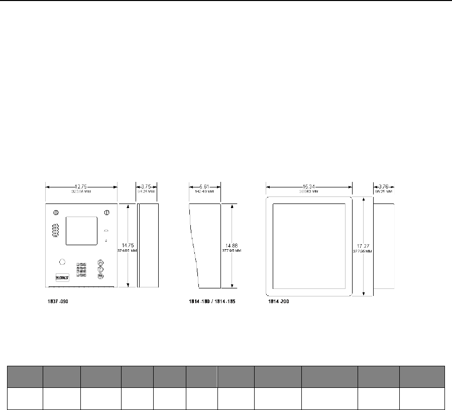
PRICE SCHEDULE A 2.0
Telephone Entry & Access Control Systems January 2019
Page 28 Specifications subject to change without notice.
1837 Telephone Entry System – 90 Series
Residential, Commercial
1837
• Larger cabinet, one design
• Dual locks, double weather seal
• Space for card reader, IP camera, TCP-IP adapter
• Optional 10 ga. hood, stainless steel or black
• Stainless steel flush kit
• 31 security (permission) levels
• 32 holiday schedules
• True anti-pass back features
• 10 and 11 digit dialing
• Eight (8) hold open time zones
Page Rev 1/2/19
Model1
Phone
Numbers
Directory
Entry
Codes2
Device
Codes3
Relays
Auxiliary
Inputs4
Expansion5
PC
Programmable6
Elevator
Control
Transaction
Buffer
1837 3000 8-Line
Electronic 3000 8000 3 2 48 Max Yes Yes 8000
1. Card reader mounting will accommodate the following card readers only: 1815-302 (DK Prox), 1815-380 (HID), 1815-215 (ID-Teck).
2. Entry codes are four (4) digits only and are not the same as device codes. Entry codes grant access when entered on the entry system keypad (or
secondary keypad) only.
3. Device codes refer to any five (5) digit 26-bit wiegand device used to access an entry point, such as cards, transmitters or PINs (Personal
Identification Number). Five (5) digit device codes can also be used on the system keypad.
4. 1837 has two 26-bit wiegand inputs.
5. Up to 48 additional entry points can be controlled via card readers, AVID tag readers, RF receivers or digital keypads using tracker expansion
boards.
6. Programming and transaction analysis software available for free download at doorking.com.

January 2019 PRICE SCHEDULE A 2.0
Telephone Entry & Access Control Systems
Specifications subject to change without notice. Page 29
1837 Telephone Entry Systems – 90 Series
Residential, Commercial
1837 Telephone Entry System
1837-090 .................................................................... 6406.00
Service Connection Options
1800-080 Cellular Voice + Data1 ................................... 654.00
2334-080 VoIP - TCP/IP Control Box3,5.......................... 522.00
1815-568 VoIP Adapter2,4 ............................................. 128.00
1830-186 Plug & Play3,4 (Plug & Play) ........................... 228.00
1830-185 Network Adapter (Manual Setup) ................ 228.00
1 – DKS Cellular subscription required.
2 – DKS VoIP subscription required.
3 – DKS VoIP or Data over IP subscription required.
4 – 1815-568 is required for voice, 1830-186 or 1830-185 is required
for data
5 – Combines the 1815-568 and 1830-186 into a common housing with
built-in ethernet switch.
Programming Only Connection Options
1508-055 RS232 to RS422 Conversion Kit .................. 1264.00
1815-037 USB to RS232 Adapter .................................. 180.00
1818-040 RS232 Connecting Cable 6-ft (1.8m) .............. 48.16
Accessories
1814-180 Stainless Steel Hood (10 ga) ......................... 430.00
1814-185 Black Hood (10 ga) ....................................... 214.00
1814-200 Flush Kit (Rough-in box + trim ring) .............. 606.00
1506-081 Secondary Keypad surface mount ................ 444.00
1506-091 Secondary Keypad flush mount .................... 576.00
1720-080 LED Light Kit ................................................. 444.00
1804-193 External Speaker .......................................... 202.00
1801-008 Backup Battery 12-Volt .8 Ah ......................... 91.52
2600-584 Heater Kit ..................................................... 170.00
1812-145 Camera ....................................................... 1022.00
1807-012 Handset Kit (surface mount only) ..................... 422.00
1830-315 TTY Add-on kit .............................................. 348.00
Expansion Options
2358-010 Tracker Expansion Board .............................. 516.00
2351-080 Sgl Box1 (1 board max) .................................... 698.00
2351-084 Sgl Box1 + 1489-080 2.4 GHz RF Module .... 1142.00
2351-085 Sgl Box1 + 1490-080 900 MHz RF Module .. 1142.00
2351-082 QUAD Box1 Pre-wired (4 boards max) ........... 1206.00
1 – Includes one (1) 2358-010 board and 16V, 40 VA transformer.
Expansion Option Wireless Kits
2361-080 Base Board Kit1 2.4 GHz ................................ 576.00
2333-080 Base Board Kit1 900 MHz .............................. 620.00
1489-080 Expansion Board Kit2 2.4 GHZ ....................... 304.00
1470-080 Expansion Board Kit2 900 MHZ ..................... 368.00
2364-080 Single channel repeater 2.4 GHz .................. 306.00
2372-080 Dual channel repeater 2.4 GHz .................... 440.00
2332-080 Dual channel repeater 900 MHz................... 578.00
1 - One (1) base board kit is installed in the 1833 controller.
2 – Expansion board kit(s) are installed on each 2358 tracker board.
1514-075 2.4 GHz antenna extension kit ....................... 60.18
1514-079 900 MHz antenna extension kit ..................... 60.18
8064-046 Coax cable extension 13-ft (3.9m) .................. 49.38
1514-004 Disk antenna 2.4 GHz ..................................... 36.12
1514-003 Six inch (152mm) antenna 2.4 GHz ................ 54.60
1514-028 Disk antenna 900 MHz ................................... 33.60
1514-019 Six inch (152mm) antenna 900 MHz .............. 33.60
1514-130 Wireless range test kit 2.4 GHz .................... 838.00
Elevator Control
2348-0401 Elevator control board + hardware ........... 2216.00
2348-0802 Lockable enclosure ................................... 2868.00
2348-0813 Lockable enclosure large ........................... 3130.00
1 – Includes board and mounting hardware.
2 – Includes one (1) 2348-010 board. Room for two (2) boards’ total.
3 – Includes one (1) 2340-010 board. Room for four (4) boards’ total.
Page Rev 1/2/19
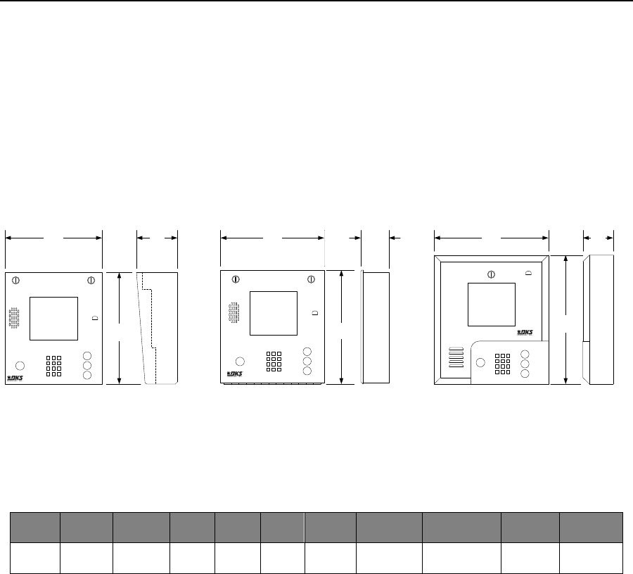
PRICE SCHEDULE A 2.0
Telephone Entry & Access Control Systems January 2019
Page 30 Specifications subject to change without notice.
1837 Telephone Entry System – 80 Series
Residential, Commercial
1837
• Full duplex voice communication
• Stores up to 3000 phone numbers
• 255 area codes
• Programmable directory codes
• 10 and 11 digit dialing
• Built-in clock/calendar
• Three (3) built-in relays
• Two (2) 26-bit wiegand inputs
• Expandable to control up to 24 entrances
• 31 security (permission) levels
• 32 holiday schedules
• True anti-pass back features
15.00
381.00 mm
13.25
336.55 mm
13.00
4.75 3.25 3.5011.25
Surface Mount Flush Mount
12.00 13.25
Wall Mount
285.75 mm 120.65 mm
330.20 mm
304.80 mm 82.55 mm 336.55 mm 88.90 mm
123
456
789
*0 #
A
Z
Call
123
456
789
*0 #
A
Z
Call
A
Z
Call
1 2 3
4 5 6
7 8 9
*0 #
Model
Phone
Numbers
Directory
Entry
Codes1
Device
Codes2
Relays
Auxiliary
Inputs3
Expansion4
PC
Programmable5
Elevator
Control
Transaction
Buffer
1837 3000 8-Line
Electronic 3000 8000 3 2 48 Max Yes Yes 8000
1. Entry codes are four (4) digits only and are not the same as device codes. Entry codes grant access when entered on the entry system keypad (or
secondary keypad) only.
2. Device codes refer to any five (5) digit 26-bit wiegand device used to access an entry point, such as cards, transmitters or PINs (Personal
Identification Number). Five (5) digit device codes can also be used on the system keypad.
3. 1837 has two 26-bit wiegand inputs.
4. Up to 48 additional entry points can be controlled via card readers, AVID tag readers, RF receivers or digital keypads using tracker expansion
boards.
5. Programming and transaction analysis software available for free download at doorking.com.
Page Rev 1/2/19

January 2019 PRICE SCHEDULE A 2.0
Telephone Entry & Access Control Systems
Specifications subject to change without notice. Page 31
1837 Telephone Entry Systems – 80 Series
Residential, Commercial
1837 Telephone Entry System
1837-080 Surface Mount ........................................... 6140.00
1837-084 Flush Mount ............................................... 6140.00
1837-089 Wall Mount ................................................ 6406.00
Service Connection Options
1800-080 Cellular Voice + Data1 ................................... 654.00
2334-080 VoIP - TCP/IP Control Box3,5.......................... 522.00
1815-568 VoIP Adapter2,4 ............................................. 128.00
1830-186 Plug & Play3,4 (Plug & Play) ........................... 228.00
1830-185 Network Adapter (Manual Setup) ................ 228.00
1 – DKS Cellular subscription required.
2 – DKS VoIP subscription required.
3 – DKS VoIP or Data over IP subscription required.
4 – 1815-568 is required for voice, 1830-186 or 1830-185 is required
for data
5 – Combines the 1815-568 and 1830-186 into a common housing with
built-in Ethernet switch.
Programming Only Connection Options
1508-055 RS232 to RS422 Conversion Kit .................. 1264.00
1815-037 USB to RS232 Adapter .................................. 180.00
1818-040 RS232 Connecting Cable 6-ft (1.8m) .............. 48.16
Accessories
1803-150 Surface Mount Trim Ring Black .................... 236.00
1814-165 Flush Mount Kit Stainless Steel .................... 396.00
1814-152 Surface Mount Ring for Flush Units.............. 236.00
1506-081 Secondary Keypad surface mount ................ 444.00
1506-091 Secondary Keypad flush mount .................... 576.00
1720-080 LED Light Kit ................................................. 444.00
1804-193 External Speaker .......................................... 202.00
1801-008 Backup Battery 12-Volt .8 Ah ......................... 91.52
2600-584 Heater Kit ..................................................... 170.00
1812-145 Camera (use with flush & wall mount) ............. 1022.00
1812-147 Camera (use with surface mount) ................... 1022.00
1807-012 Handset Kit (surface mount only) ..................... 422.00
1830-315 TTY Add-on kit .............................................. 348.00
Expansion Options
2358-010 Tracker Expansion Board .............................. 516.00
2351-080 Sgl Box1 (1 board max) .................................... 698.00
2351-084 Sgl Box1 + 1489-080 2.4 GHz RF Module .... 1142.00
2351-085 Sgl Box1 + 1490-080 900 MHz RF Module .. 1142.00
2351-082 QUAD Box1 Pre-wired (4 boards max) ........... 1206.00
1 – Includes one (1) 2358-010 board and 16V, 40 VA transformer.
Expansion Option Wireless Kits
2361-080 Base Board Kit1 2.4 GHz ................................ 576.00
2333-080 Base Board Kit1 900 MHz .............................. 620.00
1489-080 Expansion Board Kit2 2.4 GHZ ....................... 304.00
1470-080 Expansion Board Kit2 900 MHZ ..................... 368.00
2364-080 Single channel repeater 2.4 GHz .................. 306.00
2372-080 Dual channel repeater 2.4 GHz .................... 440.00
2332-080 Dual channel repeater 900 MHz................... 578.00
1 - One (1) base board kit is installed in the 1833 controller.
2 – Expansion board kit(s) are installed on each 2358 tracker board.
1514-075 2.4 GHz antenna extension kit ....................... 60.18
1514-079 900 MHz antenna extension kit ..................... 60.18
8064-046 Coax cable extension 13-ft (3.9m) .................. 49.38
1514-004 Disk antenna 2.4 GHz ..................................... 36.12
1514-003 Six inch (152mm) antenna 2.4 GHz ................ 54.60
1514-028 Disk antenna 900 MHz ................................... 33.60
1514-019 Six inch (152mm) antenna 900 MHz .............. 33.60
1514-130 Wireless range test kit 2.4 GHz .................... 838.00
Elevator Control
2348-0401 Elevator control board + hardware ........... 2216.00
2348-0802 Lockable enclosure ................................... 2868.00
2348-0813 Lockable enclosure large ........................... 3130.00
1 – Includes board and mounting hardware.
2 – Includes one (1) 2348-010 board. Room for two (2) boards’ total.
3 – Includes one (1) 2340-010 board. Room for four (4) boards’ total.
Page Rev 1/2/19
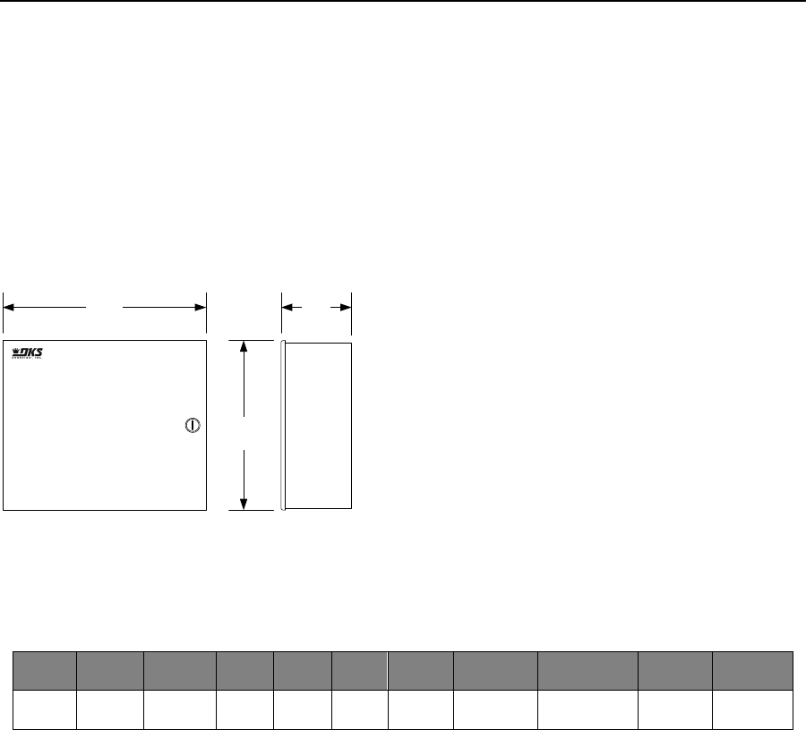
PRICE SCHEDULE A 2.0
Telephone Entry & Access Control Systems January 2019
Page 32 Specifications subject to change without notice.
1838 Access Controller
Commercial
1838
• Stores up to 3000 user names
• Programmable directory codes
• Built-in clock/calendar
• Voice communication capability
• Optional plug-in programming display
• Two (2) built-in relays control relays
• Two (2) 26-bit wiegand inputs
• Expandable to control up to 24 entrances
• 31 security (permission) levels
• 32 holiday schedules
• True anti-pass back features
4.2512.25
311.15 mm 107.95 mm
10.25
260.35 mm
Model
User
Names
Directory
Entry
Codes1
Device
Codes2
Relays
Auxiliary
Inputs3
Expansion4
PC
Programmable5
Elevator
Control
Transaction
Buffer
1838 3000 N / A 3000 8000 2 2 48 Max Yes Yes 8000
1. Entry codes are four (4) digits only and are not the same as device codes. Entry codes grant access when entered on the entry system keypad (or
secondary keypad) only.
2. Device codes refer to any five (5) digit 26-bit wiegand device used to access an entry point, such as cards, transmitters or PINs (Personal
Identification Number). Five (5) digit device codes can also be used on the system keypad.
3. 1838 has two 26-bit wiegand inputs.
4. Up to 48 additional entry points can be controlled via card readers, AVID tag readers, RF receivers or digital keypads using tracker expansion
boards.
5. Programming and transaction analysis software available for free download at doorking.com.
Page Rev 1/2/19

January 2019 PRICE SCHEDULE A 2.0
Telephone Entry & Access Control Systems
Specifications subject to change without notice. Page 33
1838 Access Controller
Commercial
1838 Access Controller
1838-081 Surface Mount ........................................... 2098.00
Service Connection Options
1800-080 Cellular Voice + Data1 ................................... 654.00
2334-080 VoIP - TCP/IP Control Box3,5.......................... 522.00
1815-568 VoIP Adapter2,4 ............................................. 128.00
1830-186 Plug & Play3,4 (Plug & Play) ........................... 228.00
1830-185 Network Adapter (Manual Setup) ................ 228.00
1 – DKS Cellular subscription required.
2 – DKS VoIP subscription required.
3 – DKS VoIP or Data over IP subscription required.
4 – 1815-568 is required for voice, 1830-186 or 1830-185 is required
for data
5 – Combines the 1815-568 and 1830-186 into a common housing with
built-in Ethernet switch.
Programming Only Connection Options
1508-055 RS232 to RS422 Conversion Kit .................. 1264.00
1815-037 USB to RS232 Adapter .................................. 180.00
1818-040 RS232 Connecting Cable 6-ft (1.8m) .............. 48.16
Call Stations1, 2
1838-120 Call station w/keypad ................................... 868.00
1838-121 Call Station w/ID Tech card reader ............... 700.00
1838-122 Call station w/AWID card reader .................. 686.00
1838-123 Call station w/HID card reader ..................... 926.00
1838-124 Call station w/DK Prox card reader .............. 602.00
1494-010 Microphone combiner3 .................................. 72.24
1 – Provides voice communication via telephone communication.
2 – Requires active telephone line.
3 – Use if two call stations will share the same telephone line.
Accessories
1838-220 1 x 20 LCD Programming Display .................. 868.00
1506-081 Secondary Keypad surface mount ................ 444.00
1506-091 Secondary Keypad flush mount .................... 576.00
1801-008 Backup Battery 12-Volt .8 Ah ......................... 91.52
Expansion Options
2358-010 Tracker Expansion Board .............................. 516.00
2351-080 Sgl Box1 (1 board max) .................................... 698.00
2351-084 Sgl Box1 + 1489-080 2.4 GHz RF Module .... 1142.00
2351-085 Sgl Box1 + 1490-080 900 MHz RF Module .. 1142.00
2351-082 QUAD Box1 Pre-wired (4 boards max) ........... 1206.00
1 – Includes one (1) 2358-010 board and 16V, 40 VA transformer.
Expansion Option Wireless Kits
2361-080 Base Board Kit1 2.4 GHz ................................ 576.00
2333-080 Base Board Kit1 900 MHz .............................. 620.00
1489-080 Expansion Board Kit2 2.4 GHZ ....................... 304.00
1470-080 Expansion Board Kit2 900 MHZ ..................... 368.00
2364-080 Single channel repeater 2.4 GHz .................. 306.00
2372-080 Dual channel repeater 2.4 GHz .................... 440.00
2332-080 Dual channel repeater 900 MHz................... 578.00
1 - One (1) base board kit is installed in the 1833 controller.
2 – Expansion board kit(s) are installed on each 2358 tracker board.
1514-075 2.4 GHz antenna extension kit ....................... 60.18
1514-079 900 MHz antenna extension kit ..................... 60.18
8064-046 Coax cable extension 13-ft (3.9m) .................. 49.38
1514-004 Disk antenna 2.4 GHz ..................................... 36.12
1514-003 Six inch (152mm) antenna 2.4 GHz ................ 54.60
1514-028 Disk antenna 900 MHz ................................... 33.60
1514-019 Six inch (152mm) antenna 900 MHz .............. 33.60
1514-130 Wireless range test kit 2.4 GHz .................... 838.00
Elevator Control
2348-0401 Elevator control board + hardware ........... 2216.00
2348-0802 Lockable enclosure ................................... 2868.00
2348-0813 Lockable enclosure large ........................... 3130.00
1 – Includes board and mounting hardware.
2 – Includes one (1) 2348-010 board. Room for two (2) boards’ total.
3 – Includes one (1) 2340-010 board. Room for four (4) boards’ total.
Page Rev 1/2/19
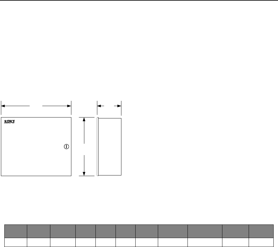
PRICE SCHEDULE A 2.0
Telephone Entry & Access Control Systems January 2019
Page 34 Specifications subject to change without notice.
1838 Access Plus Controller
Residential, Commercial
1838 AP
• Stores up to 100 user names
• Programmable directory codes
• Built-in clock/calendar
• Voice communication capability
• Optional plug-in programming display
• Control up to 8 entry points
• IP Addressable
• PC Programmable
• 2-Digit directory codes
• 20-digit dialing
• Includes 16 VAC power transformer
4.2512.25
311.15 mm 107.95 mm
10.25
260.35 mm
Page Rev 1/2/19
Model
Phone
Numbers
Directory
Names
Entry
Codes1
Device
Codes2
Relays
Auxiliary
Inputs3
Expansion4
PC
Programmable5
Temporary
Codes
Holiday
Schedules
1838 AP 27 N/A 50 100 2 2 6 Max Yes 10 Yes
1. Entry codes are four (4) digits only and are not the same as device codes. Entry codes grant access when entered on the entry system keypad (or
secondary keypad) only.
2. Device codes refer to any five (5) digit RS-485 device used to access an entry point, such as cards, transmitters or PINs (Personal Identification
Number). Five (5) digit device codes can also be used on the system keypad.
3. 1838 AP uses a standard RS-485 data input.
4. Six (6) additional entry points can be controlled via RS-485 card readers, AVID tag readers, RF receivers or digital keypads.
5. AP Programming software available for free download at doorking.com.

January 2019 PRICE SCHEDULE A 2.0
Telephone Entry & Access Control Systems
Specifications subject to change without notice. Page 35
1838 Access Plus Controller
Residential, Commercial
1838 Access Plus Controller
1838-095 Surface Mount ........................................... 1866.00
Service Connection Options
1800-081 Cellular Voice + Data1 ................................... 654.00
1815-568 VoIP Adapter2 ............................................... 128.00
1 – DKS Cellular subscription required.
2 – DKS VoIP subscription required.
1838 AP (ACCESS PLUS ONLY) Expansion Options
2354-010 Conversion Board ......................................... 180.00
1815-235 Conversion Board w/Enclosure .................... 316.00
Converts 26-bit Wiegand to RS-485. Requires 12-16 VDC power.
1812-020 12-VDC, 1A Transformer ................................ 51.62
1200-080 Transformer Box .......................................... 234.00
1816-083 Intercom Phone Expansion ........................ 1144.00
The 1816-083 expands the “No Phone Line” telephone intercom
interface on Access Plus systems from a single phone line up to 11
phone lines. The system can be further expanded to interface with up
to a maximum of 23 phone lines.
RS-485 Card Readers (ACCESS PLUS ONLY)1815-332 DK Prox
Reader 412.00
1815-232 ID Tech Reader ............................................. 504.00
1815-233 AWID Reader ................................................ 516.00
1815-234 HID Reader ................................................... 916.00
RS-485 Keypads (ACCESS PLUS ONLY)
1513-081 Surface Mount ............................................. 542.00
1513-082 Flush Mount ................................................. 674.00
RS-485 RF Controls (ACCESS PLUS ONLY)
8053-080 MicroPlus Receiver ....................................... 218.00
Page Rev 1/2/19
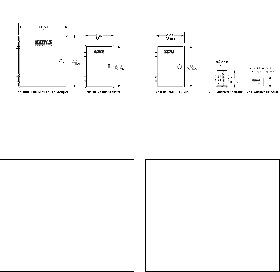
PRICE SCHEDULE A 2.0
Telephone Entry & Access Control Systems January 2019
Page 36 Specifications subject to change without notice.
Connection Options
Cellular, TCP/IP Network, VoIP
Page Rev 1/2/19
Cellular1
1800-080 Voice + Data ................................................. 654.00
1800-081 Voice + Data (AP models only) ...................... 654.00
1801-080 Voice only ..................................................... 434.00
1. Cellular subscription required.
VoIP – TCP/IP Control Box1,2
2334-080 VoIP – TCP/IP Control Box ............................ 522.00
1 – DKS VoIP or Data over IP subscription required.
2 – Combines the 1815-568 and 1830-186 into a common housing with
built-in ethernet switch.
TCP/IP Network Adapters
1830-185 (Manual setup) ............................................. 228.00
1830-1861 (Plug & Play) ................................................ 228.00
1. DKS VoIP or Data over IP subscription required.
VoIP Adapter
1815-5681 ..................................................................... 128.00
1. DKS VoIP subscription required.
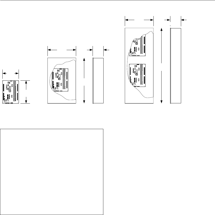
January 2019 PRICE SCHEDULE A 2.0
Telephone Entry & Access Control Systems
Specifications subject to change without notice. Page 37
Model 2348
Elevator Control
7.50
10.63
2348-010
21.25
2348-080
13.25
2348-081
35.25
5.00
190 mm
270 mm
13.25
367 mm
540 mm
127 mm
5.00
367 mm 127 mm
895 mm
Page Rev 1/2/19
Elevator Control Board
2348-040 .................................................................... 2216.00
• Includes mounting hardware.
Enclosures1
2348-080 .................................................................... 2868.00
• Maximum two (2) 2348 boards.
2348-081 .................................................................... 3130.00
• Maximum four (4) 2348 boards.
1. Includes one (1) 2348 control board and power transformer.
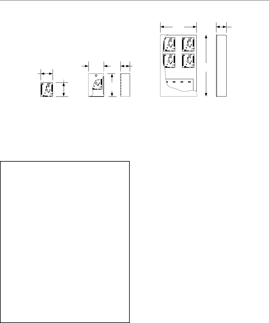
PRICE SCHEDULE A 2.0
Telephone Entry & Access Control Systems January 2019
Page 38 Specifications subject to change without notice.
Expansion Boards
Tracker Expansion Boards
4.63 5.50
2358-010
6.00
9.00
3.63
2351-080
2351-084
2351-085
24.38
14.25
2351-082
4.00
102 mm
362 mm
619 mm
229 mm
92 mm152 mm
118 mm 140 mm
Page Rev 1/2/19
Tracker Expansion Board
2358-010 ...................................................................... 516.00
Enclosures
2351-080 ...................................................................... 698.00
• Includes one (1) 2358-010 board and 16V, 20 VA
transformer.
2351-084 .................................................................... 1142.00
• Includes one (1) 2358-010 board, 1489-080 RF Module,
2.4 GHz and 16V, 20 VA transformer.
2351-085 .................................................................... 1018.00
• Includes one (1) 2358-010 board, 1470-080 RF Module,
900 MHz and 16V, 20 VA transformer.
2351-082 .................................................................... 1206.00
• Includes one (1) 2358-010 board and 16V, 40 VA
transformer.
• Can hold a maximum four (4) 2358-010 boards.
• Pre-wired.
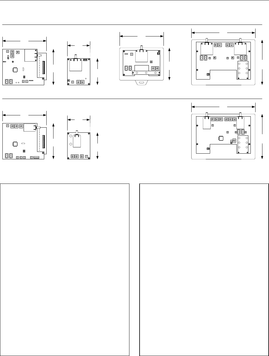
January 2019 PRICE SCHEDULE A 2.0
Telephone Entry & Access Control Systems
Specifications subject to change without notice. Page 39
Wireless Kits
Tracker Expansion Board Wireless Kits
1489-080 Expansion
3.50
4.75
2364-080 Repeater 2372-080 Repeater
2361-080 Baseboard
121 mm
89 mm
2333-080 Baseboard 1470-080 Expansion
2.4 GHz
900 MHz
4.92
125 mm
6.89
175 mm
4.92
125 mm
6.89
175 mm
3.88
98 mm
3.88
98 mm
4.75
121 mm
4.75
121 mm
2.44
62 mm
2.44
62 mm
2.88
73 mm
2.88
73 mm
2332-080 Repeater
Page Rev 1/2/19
Accessories
1514-075 Antenna Kit 2.4 GHz ....................................... 60.18
1514-079 900 MHz ......................................................... 60.18
• Includes 6-inch antenna, mounting bracket and 13-feet
cable.
8064-046 Extension Cable .............................................. 49.38
• Use with 1514-075 and 1514-079.
Antennas
1514-003 6-inch Antenna 2.4 GHz ................................. 54.60
1514-004 Disk Antenna 2.4 GHz ..................................... 36.12
1514-019 6-inch Antenna 900 MHz ................................ 33.60
1514-028 Disk Antenna 900 MHz ................................... 33.60
Field Range Test Kit 2.4 GHz only
1514-130 ...................................................................... 838.00
• Includes a simulated Baseboard Kit, simulated
Expansion Board Kit and 1514-075 Antenna Kit.
• Use to verify a good wireless connection between base
and remote stations.
Baseboard Kits
2361-080 2.4 GHz ......................................................... 576.00
2333-080 900 MHz ....................................................... 620.00
• Plugs into the 1830 series control board.
• Includes antenna kit and vandal resistant disk antenna.
Expansion Board Kits
1489-080 2.4 GHz ......................................................... 304.00
1470-080 900 MHz ....................................................... 368.00
• Plugs into the 2358 expansion board.
• Includes 6-inch and vandal resistant disk antenna.
Single Channel Repeater
2364-080 2.4 GHz ......................................................... 306.00
• Extends the range when a single 1489 kit is in use.
Dual Channel Repeaters
2372-080 2.4 GHz ......................................................... 440.00
2332-080 900 MHz ....................................................... 578.00
• Extends the range when multiple 1470 or 1489 kits are
in use.
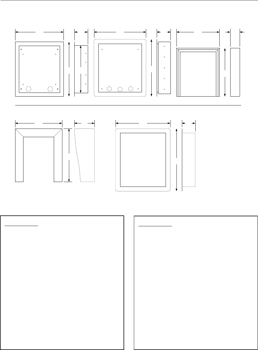
PRICE SCHEDULE A 2.0
Telephone Entry & Access Control Systems January 2019
Page 40 Specifications subject to change without notice.
Mounting Kits
Telephone Entry System Mounting Kits
13.50
15.25
1803-150 1814-165
14.50
16.00
3.88
3.75
13.25
1814-152
13.50
12.00 2.63
305 mm
343 mm
67 mm
406 mm
368 mm 98 mm
336 mm387 mm
343 mm 95 mm
5.61
142.5 MM
14.88
378 MM
15.34
389.6 MM
17.27
378 MM
3.76
95.25 MM
1814-180 / 1814-185
1814-200
13.08
332 MM
Use with 1834, 1835, 1837 -90 Series only
Use with 1803, 1810 and 1833, 1834, 1835, 1837 -80 Series only
Page Rev 1/2/19
80 Series Only
Surface Mount Trim Ring - Black
1803-150 ...................................................................... 236.00
• Use with surface mount 1803, 1810, 1833, 1834, 1835
and 1837 80 Series only.
Flush Kit Stainless Steel
1814-165 ...................................................................... 396.00
• Use with flush mount 1803, 1810, 1833, 1834, 1835 and
1837 80 Series only.
Surface Mount Adapter for Flush Units
1814-152 ...................................................................... 236.00
• Allows a flush mount unit to be mounted directly to a
flat surface. Indoor use only.
• Use with flush mount 1803, 1810, 1833, 1834, 1835 and
1837 80 Series only.
90 Series Only
Hood – Stainless Steel
1814-180 ...................................................................... 430.00
• Use with 1834-090, 1835-090 and 1837-090 systems
only.
Hood – Black
1814-185 ...................................................................... 214.00
• Use with 1834-090, 1835-090 and 1837-090 systems
only.
Flush Kit Stainless Steel (rough-in box + trim ring)
1814-200 ...................................................................... 606.00
• Use with 1834-090, 1835-090 and 1837-090 systems
only.
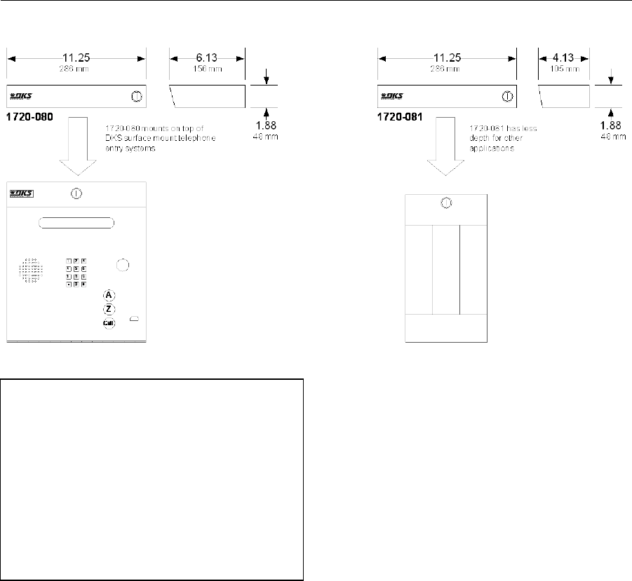
January 2019 PRICE SCHEDULE A 2.0
Telephone Entry & Access Control Systems
Specifications subject to change without notice. Page 41
Model 1720
Telephone Entry System LED Light Kit
LED Light Kit - Long
1720-080 ...................................................................... 444.00
• Use with surface mount 1803, 1810, 1833, 1834, 1835
and 1837 systems.
LED Light Kit - Short
1720-081 ...................................................................... 432.00
• Use with add-on directory.
Page Rev 1/2/19
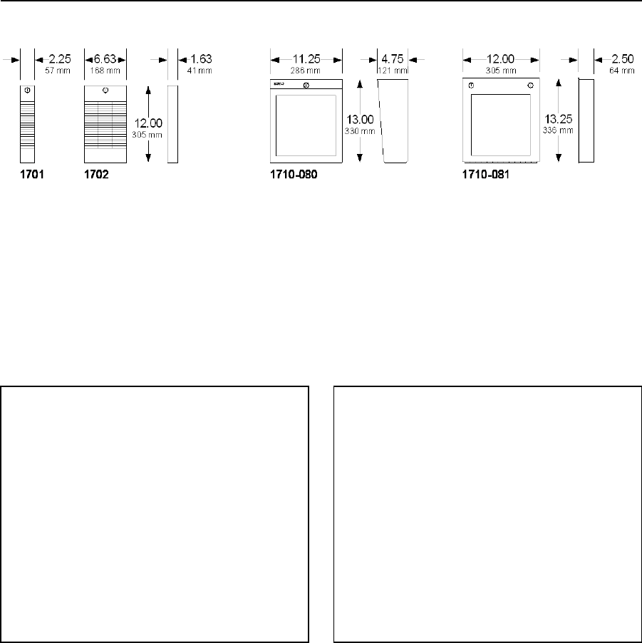
PRICE SCHEDULE A 2.0
Telephone Entry & Access Control Systems January 2019
Page 42 Specifications subject to change without notice.
Model 1701 / 1702 / 1710
Add-On Directories
Page Rev 1/2/19
Add-On Directories – Non-Lighted
1701-080 ...................................................................... 156.00
• 20 name capacity.
1702-080 ...................................................................... 228.00
• 60 name capacity.
Add-On Directories – LED Lighted
1710-080 Surface Mount .............................................. 484.00
1710-081 Flush Mount ................................................. 484.00
• These directories use 8-1/2 x 11 sheet paper. Make
your own directory with a word processor program.
Lighted Directory Mounting Accessories
1803-150 Surface Mount recess kit .............................. 236.00
• Use with the 1710-080 directory.
1814-165 Flush Mount kit ............................................ 396.00
• Use with the 1710-081 directory.
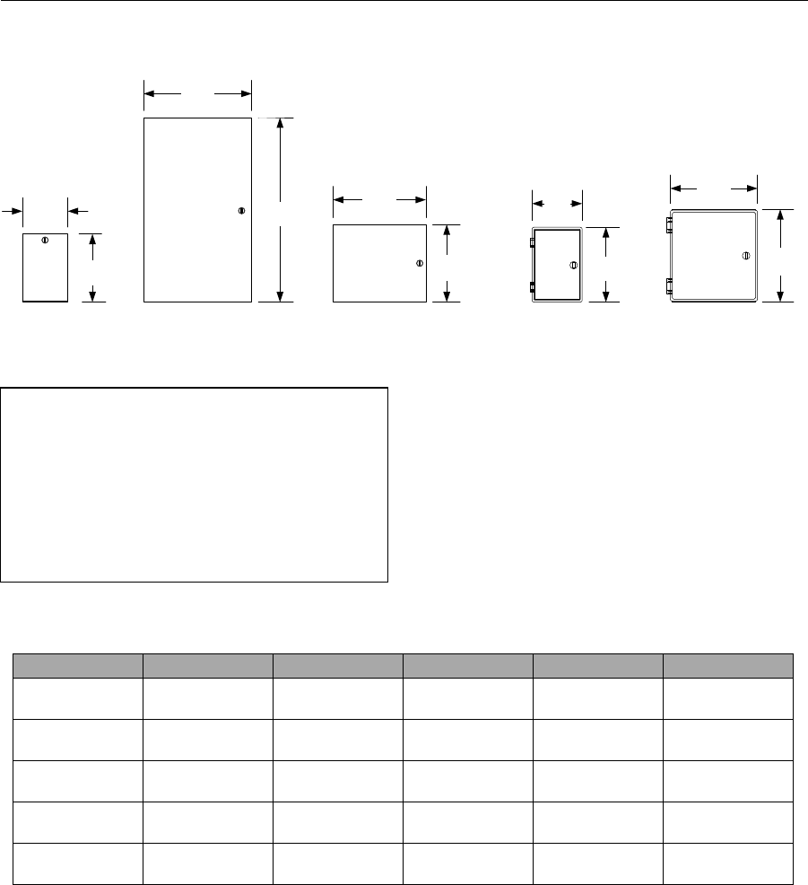
January 2019 PRICE SCHEDULE A 2.0
Telephone Entry & Access Control Systems
Specifications subject to change without notice. Page 43
General Purpose Utility Enclosures
Telephone Entry System Accessories
0102-080 0102-081
9.00
229 mm
6.00
152 mm
14.25
362 mm
24.38
619 mm
12.25
311 mm
10.25
260 mm
0102-082 0102-083 0102-084
12.25
311 mm
11.50
292 mm
6.63
168 mm
9.88
251 mm
Page Rev 1/2/19
General purpose enclosures have no power receptacles or
terminal strips, carry no warranty and are not listed.
0102-080 Small lockable metal enclosure .................... 136.00
0102-081 Large lockable metal enclosure .................... 378.00
0102-082 Medium lockable metal enclosure................ 184.00
0102-083 Small lockable plastic enclosure ................... 164.00
0102-084 Medium lockable plastic enclosure .............. 184.00
Part Number
Height
Width
Depth
Material
Lockable
0102-080
9.00
(229mm)
6.00
(152mm)
3.63
(92mm) Metal Yes
0102-081
24.38
(619mm)
14.25
(362mm)
4.00
(102mm) Metal Yes
0102-082
10.25
(260mm)
12.25
(311mm)
4.25
(108mm) Metal Yes
0102-083
9.88
(251mm)
6.63
(168mm)
4.00
(102mm) Plastic Yes
0102-084
12.25
(311mm)
11.50
(292mm)
6.00
(152mm) Plastic Yes

PRICE SCHEDULE A 2.0
Telephone Entry & Access Control Systems January 2019
Page 44 Specifications subject to change without notice.
Accessories
Handset Kits, Isolation Transformers, Miscellaneous, CCTV Camera Kits
Handset Conversion Kit
1807-012 ...................................................................... 422.00
Handset, adapter, hanger and speaker cover
Replacement Handset
1807-006 ...................................................................... 328.00
CCTV Camera Kit – High Resolution
1812-145 .................................................................... 1022.00
High resolution color camera kit (camera, mounting bracket,
wire harness, power supply)
Use this camera with the following models:
1504-080, 1504-081, 1504-082, 1504-083, 1504-084,
1504-085, 1504-086, 1504-090, 1504-091, 1504-120,
1504-121, 1504-122, 1504-123, 1504-124
1802-082, 1802-089, 1802-090, 1802-091, 1802-092
1803-080, 1803-084, 1803-090, 1803-092
1808-081, 1808-082, 1808-083, 1808-084, 1808-085
1810-084, 1810-090, 1810-096
1812-083, 1812-084, 1812-088, 1812-093, 1812-094
1819-080
1833-080, 1833-084
1834-084, 1834-089
1835-084, 1835-089
1837-080, 1837-084, 1837-089
1838-120, 1838-021, 1838-122, 1838-123, 1838-124
CCTV Camera Kit – High Resolution
1812-147 .................................................................... 1022.00
High resolution color camera kit (camera, mounting bracket,
wire harness, power supply)
Use this camera with the following models:
1810-080, 1810-088, 1810-095
1812-076, 1812-077, 1812-078, 1812-079, 1812-081,
1812-085, 1812-086, 1812-087, 1812-089, 1812-090,
1812-091, 1812-092, 1812-095, 1812-096, 1812-097
1815-247, 1815-248, 1815-249, 1815-250, 1815-251
1834-080, 1834-090
1835-080, 1835-090
1837-090
1838-228
Video Adapter
1812-039 ...................................................................... 506.00
Converts coax to twisted pair for wire runs of up to 3000-ft
(B/W) or 1600-ft (color), two required
Miscellaneous
1506-081 Secondary Keypad surface mount ................ 444.00
1506-091 Secondary Keypad flush mount .................... 576.00
1801-008 Backup Battery 12-Volt .8 AH ......................... 91.52
1804-193 External Speaker........................................... 202.00
Use in high noise areas
2600-584 Heater Kit ..................................................... 170.00
2600-588 Heater Kit ..................................................... 238.00
2600-582 LCD Heater Kit ................................................ 52.98
1816-070 Line Sense Relay ............................................. 52.98
2600-657 Replacement Key 16120 ................................... 7.60
Isolation Transformers
1830-140 ........................................................................ 77.04
Use with 1810, 1833, 1838
1808, 1810, 1812 Access Plus Systems
1830-142 ........................................................................ 77.04
Use with 1834, 1835, 1837
Key Lock Sets (Lock + 2 Keys)
4001-035 Lock #16120 (standard key lock) .................... 21.24
4001-038 Lock #16121 ................................................... 21.24
4001-039 Lock #16122 ................................................... 21.24
4001-041 Lock #16123 ................................................... 21.24
4001-042 Lock #16124 ................................................... 21.24
4001-043 Lock #16125 ................................................... 21.24
4001-044 Lock #16126 ................................................... 21.24
4001-045 Lock #16127 ................................................... 21.24
4001-046 Lock #16128 ................................................... 21.24
4001-047 Lock #16129 ................................................... 21.24
4001-048 Lock #16130 ................................................... 21.24
Page Rev 1/2/19

January 2019 PRICE SCHEDULE A 2.0
Telephone Entry & Access Control Systems
Specifications subject to change without notice. Page 45
Replacement Components
Electronic Components
Circuit Boards
1862-010 .................................................................... 1012.00
Use with 1802, 1802-EPD, 1803, 1808, 1810, 1819
1863-010 ...................................................................... 722.00
Use with all “P” series lobby panels
1871-010 .................................................................... 1474.00
Use with 1812 Classic only
1971-010 .................................................................... 1474.00
Use with 1812 Plus only
1885-010 .................................................................... 1806.00
Use with 1816 and 1820 only
1833-010 .................................................................... 1806.00
Use with 1833 only
1834-010 .................................................................... 1926.00
Use with 1834-080 and 1834-084 only
1834-009 .................................................................... 1926.00
Use with 1834-089 and 1834-090 only
1835-010 .................................................................... 2216.00
Use with 1835-080 and 1835-084 only
1835-009 .................................................................... 2216.00
Use with 1835-089 and 1835-090 only
1837-010 .................................................................... 1806.00
Use with 1837 only
1838-010 .................................................................... 1832.00
Use with 1838 only
1970-010 .................................................................... 1714.00
Use with 1802 AP, 1808 AP, 1810 AP, 1812 AP, 1838 AP
2354-010 ...................................................................... 180.00
RS-485 to Wiegand interface board
Keypads
1895-016 ...................................................................... 140.00
Keypad with letters
1895-017 ...................................................................... 140.00
Keypad no letters
1895-019 ...................................................................... 132.00
Keypad 10-pin
1804-038 ........................................................................ 25.28
Ribbon cable for 1895-016 & 1895-017
1804-155 ...................................................................... 156.00
Keypad (no letters) & ribbon cable
1804-156 ...................................................................... 156.00
Keypad (with letters) & ribbon cable
1895-032 ...................................................................... 150.00
Keypad, green back lighted
1895-060 ...................................................................... 328.00
Lighted keypad-green, A-Z-CALL button retrofit kit
1804-158 ...................................................................... 158.00
Lighted keypad-green, retrofit kit
LCD Displays
1891-010 Single-Line 20 Character .............................. 842.00
Use with 1834, 1835
1896-012 Eight-Line 20 Character ................................ 842.00
Use with 1837 only
1890-010 Single-Line 8 Character ................................ 278.00
Use with 1802, 1803 and 1810
1902-010 Single-Line 16 Character .............................. 402.00
Use with 1802 EPD only
LED Light Kits
1804-700 ........................................................................ 62.62
Use with 1810 surface mount
1804-701 ........................................................................ 24.08
Use with 1802
1804-702 ........................................................................ 43.34
Use with 1808, 1834, 1835 surface mount
1804-703 ........................................................................ 43.34
Use with 1710 directory
1804-704 ........................................................................ 24.08
Use with 1812
1804-707 ........................................................................ 43.34
Use with 1810 flush mount
Miscellaneous
1998-020 ...................................................................... 106.00
Replacement microphone kit
1998-010 ...................................................................... 106.00
Replacement microphone board
1997-190 ........................................................................ 12.64
Microphone wire harness for 1998-010 only
1804-290 ........................................................................ 28.90
5-watt speaker (square)
1817-190 ........................................................................ 40.92
Oval speaker
1815-016 ........................................................................ 25.24
Ribbon cable for 1896-018 display
Page Rev 1/2/19
PRICE SCHEDULE A 2.0
Telephone Entry & Access Control Systems January 2019
Page 46 Specifications subject to change without notice.
Blank Page

January 2019 PRICE SCHEDULE A 2.0
Access Control Devices
Prices and specifications subject to change without notice. Page 1
Section A3
This Price Schedule is effective January 7, 2019.
Access Control Devices
Date Page Comment
1-2-19 All January, 2019 Price Schedule update.
PRICE SCHEDULE A 2.0
Access Control Devices January 2019
Page 2 Prices and specifications subject to change without notice.
January 2019 PRICE SCHEDULE A 2.0
Access Control Devices
Prices and specifications subject to change without notice. Page 3
Table of Contents
Card Readers
DK Prox Proximity Card Readers ............................................................................................................................. 4
HID Card Readers .................................................................................................................................................... 6
AWID Card Readers ................................................................................................................................................ 8
ID-Teck Card Readers ........................................................................................................................................... 10
Keypads
Digital Key Pads .................................................................................................................................................... 12
RF Controls
MicroPlus RF Controls .......................................................................................................................................... 14
MicroClik RF Controls ........................................................................................................................................... 16
Miscellaneous Controls
Key Switches ......................................................................................................................................................... 18
Exit Push Buttons .................................................................................................................................................. 19
Postal & Fire Department Lock Boxes .................................................................................................................. 20
Door and Gate Locks
1200 Lb. Magnetic Door Locks ............................................................................................................................. 22
600 Lb. Magnetic Door Locks ............................................................................................................................... 23
300 Lb. Mini-locks, 2000 Lb. Shear Lock ............................................................................................................... 24
1200 Lb, 600 Lb. Magnetic gate Locks .................................................................................................................. 25
Electric Dead-bolts and Door Strikes .................................................................................................................... 26
Magnetic Door Backup Power Supplies ................................................................................................................ 27
Page Rev 1/2/19
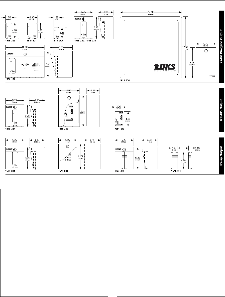
PRICE SCHEDULE A 2.0
Access Control Devices January 2019
Page 4 Prices and specifications subject to change without notice.
DK Prox Card Readers
26-Bit Wiegand Output
1815-300 Up to 3-inch range ........................................ 138.00
1815-301 Up to 4-inch range ........................................ 138.00
1815-302 Up to 2-inch range ........................................ 138.00
1815-330 (1815-300 reader w/enclosure) .................... 258.00
1815-333 (1815-330 w/expansion board) .................... 836.00
1815-350 Up to 25-feet range .................................... 2948.00
1504-124 (1815-300 w/intercom substation) ............... 614.00
RS-485 Output (ACCESS PLUS ONLY)
1815-332 Up to 3-inch range ........................................ 432.00
1815-235 (2354-010 w/enclosure) ............................... 316.00
2354-010 (26-Bit Wiegand to RS-485 converter) .......... 180.00
Relay Output (Stand Alone)
1520-084 ...................................................................... 782.00
1520-081 Controller only ............................................. 722.00
• 1520 reader/controller can store up to 1000 card codes
• 3600 event history buffer
• Built-in programming keypad
• Timed anti-pass back, hold open time zones
1524-080 (1524-331 w/enclosure)............................... 470.00
1524-331 ..................................................................... 348.00
1815-340 Replacement Programmer ............................. 57.34
• 1524 reader can store up to 1000 card codes
• Use 1815-340 hand held programmer to add / delete
individual cards or blocks of cards
Page Rev 1/2/19

January 2019 PRICE SCHEDULE A 2.0
Access Control Devices
Prices and specifications subject to change without notice. Page 5
DK Prox Cards
Cards are sold in blocks of 50 only. Special Order cards are sold in blocks of 100 only.
These cards are factory pre-coded. Card numbers may, or
may not be, in numerical sequence.
1508-120 Clamshell Cards
50-100 .............................................................................. 5.06
150-500 ............................................................................ 4.66
550-950 ............................................................................ 4.26
1000+ ............................................................................... 3.86
1508-121 ISO Graphics Cards
50-100 .............................................................................. 7.00
150-500 ............................................................................ 6.60
550-950 ............................................................................ 6.20
1000+ ............................................................................... 5.80
1508-123 Key Tags
50-100 .............................................................................. 7.48
150-500 ............................................................................ 7.08
550-950 ............................................................................ 6.68
1000+ ............................................................................... 6.28
UHF DK Prox Cards
These cards are factory pre-coded. Card numbers may, or
may not be, in numerical sequence.
1508-191 ISO Card UHF Only ......................................... 12.02
1508-198 ISO Card UHF/DK Prox Dual Tech ................... 14.20
1815-318 Windshield Holder ........................................... 4.36
1815-319 Rearview Mirror Holder ................................... 4.36
1508-191 can only be used with 1815-350 card reader. 1508-198 dual
technology card can be used with both 1815-350 and all other DK Prox
card readers.
DK Prox Cards - Special Order1
These cards include sequential coding, specific card
numbers and specific start / stop numbering sequences.
1508-127 Clamshell Cards
50-100 .............................................................................. 7.48
150-500 ............................................................................ 7.08
550-950 ............................................................................ 6.68
1000+ ............................................................................... 6.28
1508-128 ISO Graphics Cards
50-100 .............................................................................. 9.40
150-500 ............................................................................ 9.00
550-950 ............................................................................ 8.60
1000+ ............................................................................... 8.20
1508-129 Key Tags
50-100 .............................................................................. 9.90
150-500 ............................................................................ 9.50
550-950 ............................................................................ 9.10
1000+ ............................................................................... 8.70
UHF DK Prox Cards – Special Order1
These cards include sequential coding, specific card
numbers and specific start / stop numbering sequences.
1508-190 ISO Card UHF Only ......................................... 14.20
1508-197 ISO Card UHF/DK Prox Dual Tech ................... 16.38
1815-318 Windshield Holder ........................................... 4.36
1815-319 Rearview Mirror Holder ................................... 4.36
1508-195 Headlight Tag
1-50 ................................................................................ 13.10
51-150 ............................................................................ 12.30
151-500 .......................................................................... 11.50
501-999 .......................................................................... 10.70
1000+ ............................................................................... 9.90
1508-199 License Plate Tag
1-50 ................................................................................ 13.10
51-150 ............................................................................ 12.30
151-500 .......................................................................... 11.50
501-999 .......................................................................... 10.70
1000+ ............................................................................... 9.90
1508-191, 1508-195 and 1508-199 can only be used with 1815-350
card reader. 1508-198 dual technology cards can be used with both
1815-350 and all other DK Prox card readers.
Note 1: Special orders cannot be returned for credit.
Page Rev 1/2/19
DKProx Card Identifier for PC
1815-640 ...................................................................... 126.00
This stand-alone accessory connects to a PC via a USB cable and will
read the card code when presented to the identifier. This is useful for
cards that have no numbers printed on them or the card number has
worn off.
Requires software, for free download go to:
http://www.doorking.com/accessories/access-control-
accessories/dkprox-card-identifier
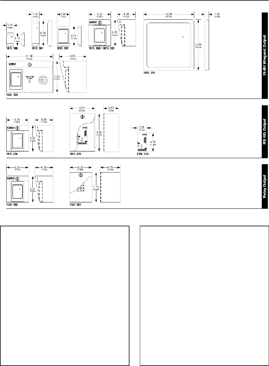
PRICE SCHEDULE A 2.0
Access Control Devices January 2019
Page 6 Prices and specifications subject to change without notice.
HID Proximity Card Readers
26-Bit Wiegand Output
1815-380 (ProxPoint Plus) Up to 3-inch range .............. 326.00
1815-381 (MiniProx) Up to 5-inch range ...................... 638.00
1815-382 (ThinLine) Up to 5-inch range ....................... 612.00
1815-390 (1815-382 reader w/enclosure) .................... 704.00
1815-392 (1815-390 w/expansion board) .................. 1222.00
1504-123 (1815-382 w/intercom substation) ............... 796.00
1815-395 (MaxiProx) Up to 6-feet range .................... 1926.00
• Use 1508-014 Active Tags with 1815-395
RS-485 Output (ACCESS PLUS ONLY)
1815-234 (ThinLine) Up to 5-inch range ....................... 916.00
1815-235 (2354-010 w/enclosure) ............................... 316.00
2354-010 (26-Bit Wiegand to RS-485 converter) .......... 180.00
Relay Output (Stand Alone)
1520-082 .................................................................... 1058.00
1520-081 Controller only ............................................. 722.00
• 1520 reader/controller can store up to 1000 card codes
• 3600 event history buffer
• Built-in programming keypad
• Timed anti-pass back, hold open time zones
Page Rev 1/2/19

January 2019 PRICE SCHEDULE A 2.0
Access Control Devices
Prices and specifications subject to change without notice. Page 7
HID Prox Cards
Cards are sold in blocks of 50 only. Special order cards are sold in blocks of 100 only.
HID Prox Cards
These cards are factory pre-coded. Card numbers may, or
may not be, in numerical sequence.
1508-018 ProxCard Clamshell Cards
50-100 .............................................................................. 7.48
150-500 ............................................................................ 7.08
550-950 ............................................................................ 6.68
1000+ ............................................................................... 6.28
1508-017 Prox ISO Graphics Cards
50-100 ............................................................................ 11.82
150-500 .......................................................................... 11.42
550-950 .......................................................................... 11.02
1000+ ............................................................................. 10.62
1508-016 ProxKey Key Tags
50-100 ............................................................................ 12.30
150-500 .......................................................................... 11.90
550-950 .......................................................................... 11.50
1000+ ............................................................................. 11.10
HID Prox Cards - Special Order1
These cards include sequential coding, specific card
numbers and specific start / stop numbering sequences.
1508-143 ProxCard Clamshell Cards
50-100 .............................................................................. 9.90
150-500 ............................................................................ 9.50
550-950 ............................................................................ 9.10
1000+ ............................................................................... 8.70
1508-144 Prox ISO Graphics Cards
50-100 ............................................................................ 14.22
150-500 .......................................................................... 13.82
550-950 .......................................................................... 13.42
1000+ ............................................................................. 13.02
1508-145 ProxKey Key Tags
50-100 ............................................................................ 14.70
150-500 .......................................................................... 14.30
550-950 .......................................................................... 13.90
1000+ ............................................................................. 13.50
1508-014 ProxPass Active Tags (use with 1815-395 only)
1-9 .................................................................................. 95.86
10-30 .............................................................................. 92.86
40-100 ............................................................................ 89.96
110-490 .......................................................................... 86.96
500+ ............................................................................... 83.96
Note 1: Special orders cannot be returned for credit.
Page Rev 1/2/19
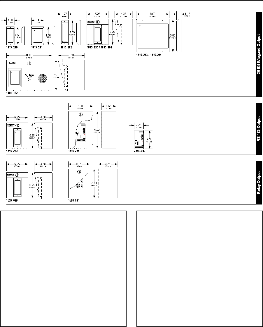
PRICE SCHEDULE A 2.0
Access Control Devices January 2019
Page 8 Prices and specifications subject to change without notice.
AWID Proximity Card Readers
RS-485 Output (ACCESS PLUS ONLY)
1815-233 Up to 3-inch range ....................................... 516.00
1815-235 (2354-010 w/enclosure) ............................... 316.00
2354-010 (26-Bit Wiegand to RS-485 converter) ......... 180.00
Relay Output (Stand Alone)
1520-080 ...................................................................... 868.00
1520-081 Controller only ............................................. 722.00
• 1520 reader/controller can store up to 1000 card codes
• 3600 event history buffer
• Built-in programming keypad
• Timed anti-pass back, hold open time zones
26-Bit Wiegand Output
1815-280 (SR 2400) Up to 4-inch range ........................ 218.00
1815-281 (SP 6820) Up to 8-inch range ........................ 390.00
1815-282 (MM 6800) Up to 2-inch range ..................... 390.00
1815-290 (1815-280 reader w/enclosure) .................... 326.00
1815-292 (1815-290 w/expansion board) .................... 842.00
1815-283 (MR 1824) Up to 24 inch range ..................... 782.00
1815-284 (MR 1824 MC) Up to 16 inch range .............. 964.00
1504-122 (1815-281 w/intercom substation) ............... 694.00
Page Rev 1/2/19

January 2019 PRICE SCHEDULE A 2.0
Access Control Devices
Prices and specifications subject to change without notice. Page 9
AWID Prox Cards
Cards are sold in blocks of 50 only. Special order cards are sold in blocks of 100 only.
AWID Prox Cards
These cards are factory pre-coded. Card numbers may, or
may not be, in numerical sequence.
1508-020 Prox-Linc Clamshell Cards
50-100 .............................................................................. 6.26
150-500 ............................................................................ 5.86
550-950 ............................................................................ 5.46
1000+ ............................................................................... 5.06
1508-021 Prox-Linc GR ISO Graphics Cards
50-100 .............................................................................. 9.52
150-500 ............................................................................ 9.12
550-950 ............................................................................ 8.72
1000+ ............................................................................... 8.32
1508-022 Prox-Linc KT Key Tags
50-100 ............................................................................ 10.12
150-500 ............................................................................ 9.72
550-950 ............................................................................ 9.32
1000+ ............................................................................... 8.92
AWID Prox Cards - Special Order1 (minimum 100)
These cards include sequential coding, specific card
numbers and specific start / stop numbering sequences.
1508-132 Prox-Linc Clamshell Cards
50-100 .............................................................................. 8.68
150-500 ............................................................................ 8.28
550-950 ............................................................................ 7.88
1000+ ............................................................................... 7.48
1508-133 Prox-Linc GR ISO Graphics Cards
50-100 ............................................................................ 11.92
150-500 .......................................................................... 11.52
550-950 .......................................................................... 11.12
1000+ ............................................................................. 10.72
1508-134 Prox-Linc KT Key Tags
50-100 ............................................................................ 12.52
150-500 .......................................................................... 12.12
550-950 .......................................................................... 11.72
1000+ ............................................................................. 11.32
Note 1: Special orders cannot be returned for credit.
Page Rev 1/2/19
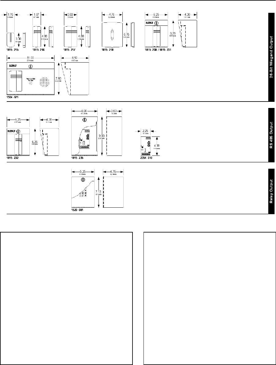
PRICE SCHEDULE A 2.0
Access Control Devices January 2019
Page 10 Prices and specifications subject to change without notice.
ID-Teck Proximity Card Readers
26-Bit Wiegand Output
1815-215 (RF Tiny) Up to 3-inch range ......................... 228.00
1815-216 (RF 10) Up to 3-inch range ............................ 228.00
1815-217 (RF 20) Up to 3-inch range ............................ 228.00
1815-218 (RF 30) Up to 12 inch range .......................... 626.00
1815-230 (1815-216 reader w/enclosure) .................... 322.00
1815-231 (1815-230 w/expansion board) .................... 826.00
1504-121 (1815-217 w/intercom substation) ............... 700.00
RS-485 Output (ACCESS PLUS ONLY)
1815-232 Up to 3-inch range ........................................ 504.00
1815-235 (2354-010 w/enclosure) ............................... 316.00
2354-010 (26-Bit Wiegand to RS-485 converter) .......... 180.00
Relay Output (Stand Alone)
1520-081 Controller only ............................................. 722.00
• 1520 reader/controller can store up to 1000 card codes
• 3600 event history buffer
• Built-in programming keypad
• Timed anti-pass back, hold open time zones
Page Rev 1/2/19

January 2019 PRICE SCHEDULE A 2.0
Access Control Devices
Prices and specifications subject to change without notice. Page 11
ID-Teck Prox Cards
Note: cards will work with the following ID-Teck Prox readers only:
1815-215, 1815-216, 1815-217, 1815-218, 1815-230, 1815-231, 1504-121
Cards are sold in blocks of 50 only. Special order cards are sold in blocks of 100 only.
ID-Teck Prox Cards
These cards are factory pre-coded. Card numbers may, or
may not be, in numerical sequence.
1508-110 RF 170 Clamshell Cards
50-100 .............................................................................. 7.32
150-500 ............................................................................ 6.92
550-950 ............................................................................ 6.52
1000+ ............................................................................... 6.12
1508-111 RF 80 ISO Graphics Cards
50-100 ............................................................................ 11.82
150-500 .......................................................................... 11.42
550-950 .......................................................................... 11.02
1000+ ............................................................................. 10.62
1508-112 RF 50 Key Tags
50-100 ............................................................................ 12.52
150-500 .......................................................................... 12.12
550-950 .......................................................................... 11.72
1000+ ............................................................................. 11.32
ID-Teck Prox Cards - Special Order1
These cards include sequential coding, specific card
numbers and specific start / stop numbering sequences.
1508-136 RF 170 Clamshell Cards
50-100 .............................................................................. 9.74
150-500 ............................................................................ 9.34
550-950 ............................................................................ 8.94
1000+ ............................................................................... 8.54
1508-137 RF 80 ISO Graphics Cards
50-100 ............................................................................ 14.22
150-500 .......................................................................... 13.82
550-950 .......................................................................... 13.42
1000+ ............................................................................. 13.02
1508-138 RF 50 Key Tags
50-100 ............................................................................ 14.94
150-500 .......................................................................... 14.54
550-950 .......................................................................... 14.14
1000+ ............................................................................. 13.74
Note 1: Special orders cannot be returned for credit.
Page Rev 1/2/19
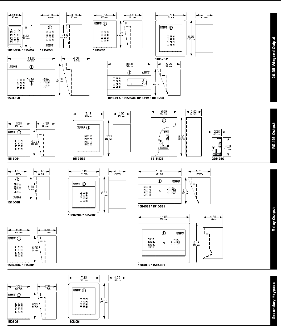
PRICE SCHEDULE A 2.0
Access Control Devices January 2019
Page 12 Prices and specifications subject to change without notice.
Keypads
Page Rev 1/2/19

January 2019 PRICE SCHEDULE A 2.0
Access Control Devices
Prices and specifications subject to change without notice. Page 13
Keypads
26-Bit Wiegand Output
These keypads must be connected to a 26-bit wiegand
controller, such as the DK 1830 Series. They are not stand-
alone devices.
1815-053 (Silver finish) ................................................ 890.00
1815-054 (Black finish) ................................................. 890.00
• Vandal resistant, piezoelectric, 5-12 VDC.
• Mounts on single-gang electric box.
1815-059 Surface Mount ............................................. 412.00
• NFC programming with DK Manager app (free from
Google Play store), Android only.
• Low power solar mode.
1815-051 Surface Mount ............................................. 532.00
1815-052 Flush Mount ................................................. 662.00
1504-120 Surface Mount w/intercom substation ........ 808.00
1815-247 Surface Mount ........................................... 1034.00
• Keypad with ID Tech (1815-216) card reader.
1815-248 Surface Mount ........................................... 1072.00
• Keypad with AWID (1815-281) card reader.
1815-249 Surface Mount ........................................... 1192.00
• Keypad with HID (1815-382) card reader.
1815-250 Surface Mount ............................................. 990.00
• Keypad with DK Prox (1815-300) card reader.
RS-485 Output (ACCESS PLUS ONLY)
These keypads must be connected to a RS-485 controller,
such as the DK Access Plus Series. They are not stand-alone
devices.
1513-081 Surface Mount ............................................. 542.00
1513-082 Flush Mount ................................................. 674.00
1815-235 (2354-010 w/enclosure) ............................... 316.00
2354-010 (26-Bit Wiegand to RS-485 converter) ......... 180.00
Relay Output (Stand Alone)
These keypads use a dry relay(s) contact and are designed
to be used as a stand-alone device.
1506-086 Surface Mount ............................................. 662.00
1506-096 Flush Mount ................................................. 796.00
1504-086 Surface Mount w/intercom substation ........ 820.00
1504-096 Flush Mount w/intercom substation .......... 1012.00
• 2 Form C dry contact relays.
• 1000 four (4) digit entry codes.
• 6 five (5) digit entry codes.
• Hold open codes.
• Time zone inputs.
1515-080 Surface Mount ............................................. 390.00
1515-081 Surface Mount ............................................. 520.00
1515-082 Flush Mount ................................................. 642.00
1504-081 Surface Mount w/intercom substation ........ 668.00
1504-091 Flush Mount w/intercom substation ............ 732.00
• 1 Form C dry contact relay.
• 400 four (4) or five (5) digit entry codes.
• Hold open codes.
• NFC programming with DK Manager app (free from
Google Play store), Android only.
• Low power solar mode.
Secondary Keypad
These keypads can only be used with DK telephone entry
systems.
1506-081 Surface Mount ............................................. 444.00
1506-091 Flush Mount ................................................. 576.00
Page Rev 1/2/19
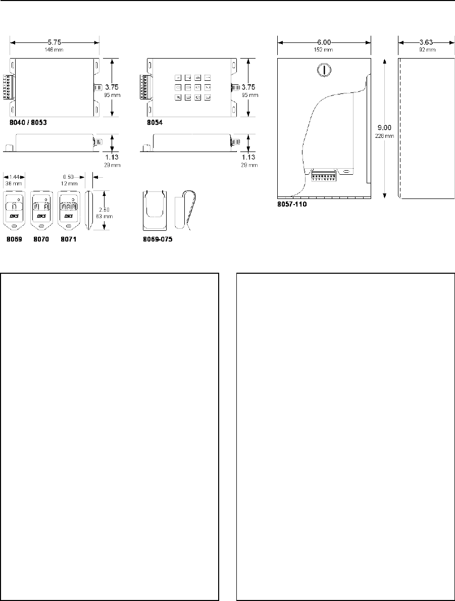
PRICE SCHEDULE A 2.0
Access Control Devices January 2019
Page 14 Prices and specifications subject to change without notice.
MicroPLUS RF Controls
26-Bit Wiegand Output
8040-080 ...................................................................... 194.00
• 5300 Transmitter codes.
• 26, 30 or 31-bit wiegand format.
8040-090 ...................................................................... 194.00
• 5300 Transmitter codes.
• 26, 30 or 31-bit wiegand format.
• Compatible with Elite Series1 DT-418 transmitters.
1. Elite Series is a registered trademark of The Chamberlain Group, Inc.
RS-485 Output (ACCESS PLUS ONLY)
8053-080 ...................................................................... 218.00
• 5300 Transmitter codes.
Relay Output (Stand Alone)
8040-080 100 Transmitter codes ................................. 194.00
• Program via the “learn” method.
• Individual codes cannot be deleted.
8054-081 50 Transmitter codes ................................... 390.00
8054-082 100 Transmitter codes ................................. 458.00
8054-083 250 Transmitter codes ................................. 520.00
8054-084 500 Transmitter codes ................................. 584.00
8054-085 1000 Transmitter codes ............................... 652.00
8054-086 1250 Transmitter codes ............................... 714.00
• Built-in time clock, 10 programmable time zones.
• 2300 event history buffer.
• Can be connected to a serial printer.
Receiver Accessories
8057-110 Lockable outdoor enclosure ......................... 116.00
1514-073 Coax Antenna kit ............................................ 57.80
1514-072 High Gain antenna 318 MHz ........................ 208.00
8052-080 Antenna Amplifier 318 MHz ......................... 240.00
Page Rev 1/2/19

January 2019 PRICE SCHEDULE A 2.0
Access Control Devices
Prices and specifications subject to change without notice. Page 15
MicroPlus Transmitters / ProxMitters (Transmitter w/proximity card reader built-in)
IMPORTANT! The prices shown are for block-coded transmitters ordered in multiples of 10 only. Add $3.00 per
transmitter for any order specifying transmitter numbering sequence or facility codes.
8069-080 1 Button
10-30.............................................................................. 37.80
40-100 ............................................................................ 35.80
110+ ............................................................................... 31.80
8070-080 2 Button
10-30.............................................................................. 39.90
40-100 ............................................................................ 37.90
110+ ............................................................................... 33.90
8071-080 3 Button
10-30.............................................................................. 42.00
40-100 ............................................................................ 40.00
110+ ............................................................................... 36.00
8069-086 1 Button w/IDTeck Tag
10-30.............................................................................. 47.26
40-100 ............................................................................ 45.26
110+ ............................................................................... 41.26
8070-086 2 Button w/IDTeck Tag
10-30.............................................................................. 49.36
40-100 ............................................................................ 47.36
110+ ............................................................................... 43.36
8071-086 3 Button w/IDTeck Tag
10-30.............................................................................. 51.46
40-100 ............................................................................ 49.46
110+ ............................................................................... 45.46
8069-082 1 Button w/AWID Tag
10-30.............................................................................. 47.26
40-100 ............................................................................ 45.26
110+ ............................................................................... 41.26
8070-082 2 Button w/AWID Tag
10-30.............................................................................. 49.36
40-100 ............................................................................ 47.36
110+ ............................................................................... 43.36
8071-082 3 Button w/AWID Tag
10-30.............................................................................. 51.46
40-100 ............................................................................ 49.46
110+ ............................................................................... 45.46
8069-084 1 Button w/HID Tag
10-30 .............................................................................. 47.26
40-100 ............................................................................ 45.26
110+ ............................................................................... 41.26
8070-084 2 Button w/HID Tag
10-30 .............................................................................. 49.36
40-100 ............................................................................ 47.36
110+ ............................................................................... 43.36
8071-084 3 Button w/HID Tag
10-30 .............................................................................. 51.46
40-100 ............................................................................ 49.46
110+ ............................................................................... 45.46
MicroPlus Visor Clips (Black)
8069-075
1-30 .................................................................................. 3.96
31-100 .............................................................................. 3.46
101+ ................................................................................. 2.96
8069-087 1 Button w/DK Prox Tag
10-30 .............................................................................. 47.26
40-100 ............................................................................ 45.26
110+ ............................................................................... 41.26
8070-087 2 Button w/DK Prox tag
10-30 .............................................................................. 49.36
40-100 ............................................................................ 47.36
110+ ............................................................................... 43.36
8071-087 3 Button w/DK Prox Tag
10-30 .............................................................................. 51.46
40-100 ............................................................................ 49.46
110+ ............................................................................... 45.46
Page Rev 1/2/19
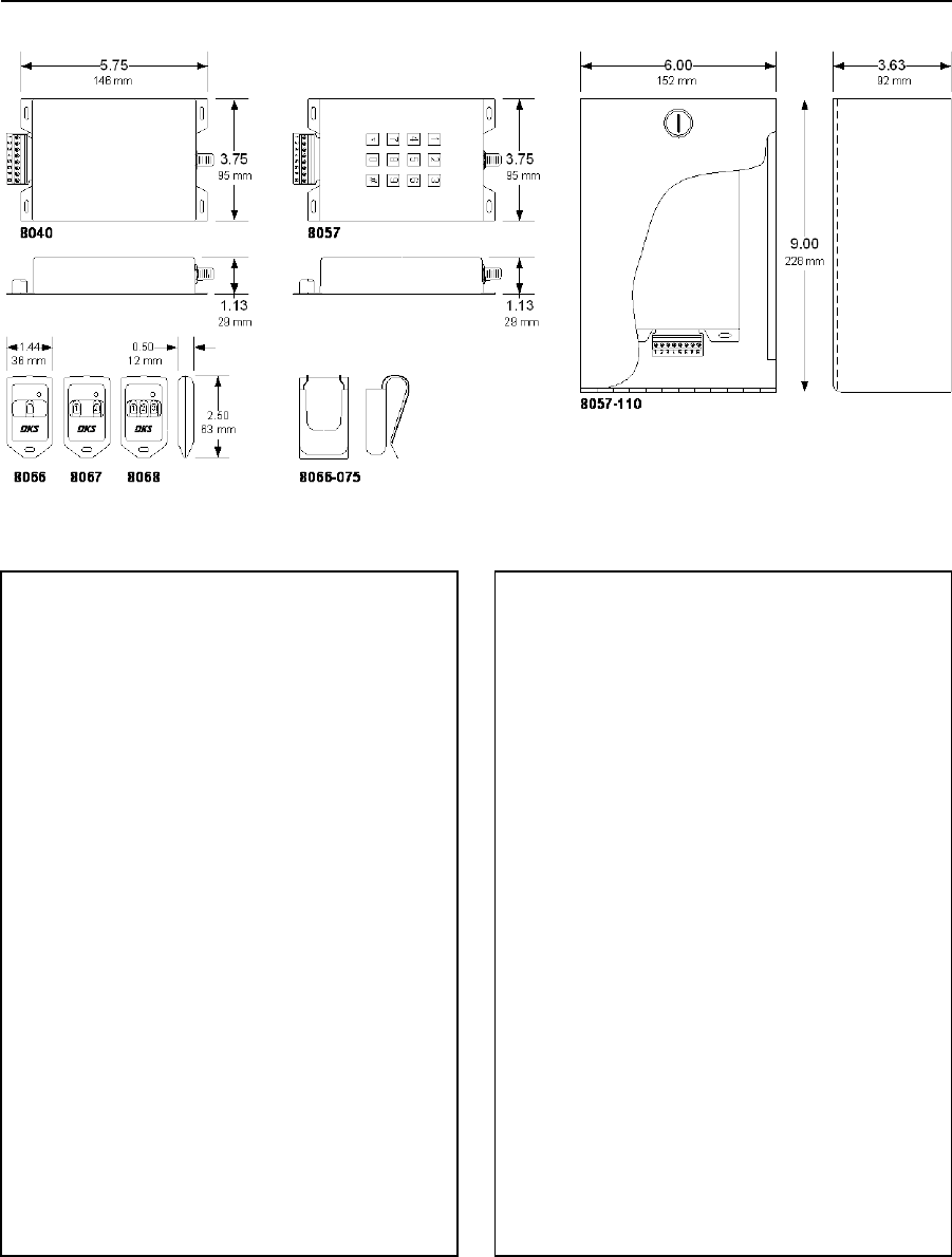
PRICE SCHEDULE A 2.0
Access Control Devices January 2019
Page 16 Prices and specifications subject to change without notice.
MicroClik RF Controls
26-Bit Wiegand Output
8040-080 ...................................................................... 194.00
• 5300 Transmitter codes.
• 26, 30 or 31-bit wiegand format.
8040-090 ...................................................................... 194.00
• 5300 Transmitter codes.
• 26, 30 or 31-bit wiegand format.
• Compatible with Elite Series1 DT-418 transmitters.
1. Elite Series is a registered trademark of The Chamberlain Group, Inc.
Relay Output (Stand Alone)
8040-080 100 Transmitter codes ................................. 194.00
• Program via the “learn” method.
• Individual codes cannot be deleted.
8057-081 50 Transmitter codes ................................... 326.00
8057-082 100 Transmitter codes ................................. 390.00
8057-083 250 Transmitter codes ................................. 452.00
8057-084 500 Transmitter codes ................................. 520.00
8057-085 1000 Transmitter codes ............................... 584.00
8057-086 5000 Transmitter codes ............................... 652.00
8057-088 16,000 Transmitter codes ............................ 714.00
• Built-in time clock, 10 programmable time zones.
• 2300 event history buffer.
• Can be connected to a serial printer.
Receiver Accessories
8057-110 Lockable outdoor enclosure ......................... 116.00
1514-073 Coax Antenna kit ............................................ 57.80
1514-072 High Gain antenna 318 MHz ........................ 208.00
8052-080 Antenna Amplifier 318 MHz ......................... 240.00
Page Rev 1/2/19

January 2019 PRICE SCHEDULE A 2.0
Access Control Devices
Prices and specifications subject to change without notice. Page 17
MicroClik Transmitters / ProxMitters (Transmitter w/proximity card reader built-in)
IMPORTANT! The prices shown are for block-coded transmitters ordered in multiples of 10 only. Add $3.00 per
transmitter for any order specifying transmitter numbering sequence or facility codes.
8066-080 1 Button
10-30.............................................................................. 39.90
40-100 ............................................................................ 37.90
110+ ............................................................................... 33.90
8067-080 2 Button
10-30.............................................................................. 42.00
40-100 ............................................................................ 40.00
110+ ............................................................................... 36.00
8068-080 3 Button
10-30.............................................................................. 44.10
40-100 ............................................................................ 42.10
110+ ............................................................................... 38.10
8066-085 1 Button w/DK Prox Tag
10-30 .............................................................................. 49.36
40-100 ............................................................................ 47.36
110+ ............................................................................... 43.36
8067-085 2 Button w/DK Prox Tag
10-30 .............................................................................. 51.46
40-100 ............................................................................ 49.46
110+ ............................................................................... 45.46
8068-085 3 Button w/DK Prox Tag
10-30 .............................................................................. 53.56
40-100 ............................................................................ 50.56
110+ ............................................................................... 46.56
8066-082 1 Button w/AWID Tag
10-30.............................................................................. 49.36
40-100 ............................................................................ 47.36
110+ ............................................................................... 43.36
8067-082 2 Button w/AWID Tag
10-30.............................................................................. 51.46
40-100 ............................................................................ 49.46
110+ ............................................................................... 45.46
8068-082 3 Button w/AWID Tag
10-30.............................................................................. 53.56
40-100 ............................................................................ 50.56
110+ ............................................................................... 46.56
8066-083 1 Button w/HID Tag
10-30 .............................................................................. 49.36
40-100 ............................................................................ 47.36
110+ ............................................................................... 43.36
8067-083 2 Button w/HID Tag
10-30 .............................................................................. 51.46
40-100 ............................................................................ 49.46
110+ ............................................................................... 45.46
8068-083 3 Button w/HID Tag
10-30 .............................................................................. 53.56
40-100 ............................................................................ 50.56
110+ ............................................................................... 46.56
MicroClik Visor Clips (Gray)
8066-075
1-30 .................................................................................. 3.96
31-100 .............................................................................. 3.46
101+ ................................................................................. 2.96
8066-084 1 Button w/IDTeck Tag
10-30.............................................................................. 49.36
40-100 ............................................................................ 47.36
110+ ............................................................................... 43.36
8067-084 2 Button w/IDTeck Tag
10-30.............................................................................. 51.46
40-100 ............................................................................ 49.46
110+ ............................................................................... 45.46
8068-084 3 Button w/IDTeck Tag
10-30.............................................................................. 53.56
40-100 ............................................................................ 50.56
110+ ............................................................................... 46.56
Page Rev 1/2/19

PRICE SCHEDULE A 2.0
Access Control Devices January 2019
Page 18 Prices and specifications subject to change without notice.
Key Switches
Mortise Key Cylinder
1206-080 ........................................................................ 99.34
• N.O. or N.C. operation.
• Mounts in single-gang electric box.
• Indoor use only.
1207-080 ...................................................................... 260.00
• N.O. or N.C. operation.
• Surface mount non-lighted enclosure.
• Indoor or outdoor use.
1209-080 ...................................................................... 444.00
• N.O. or N.C. operation.
• Surface mount lighted enclosure.
• Indoor or outdoor use.
• Intercom substation.
Ace Key Cylinder
1210-080 ...................................................................... 260.00
• N.O. or N.C. operation.
• Surface mount non-lighted enclosure.
• Indoor or outdoor use.
Page Rev 1/2/19
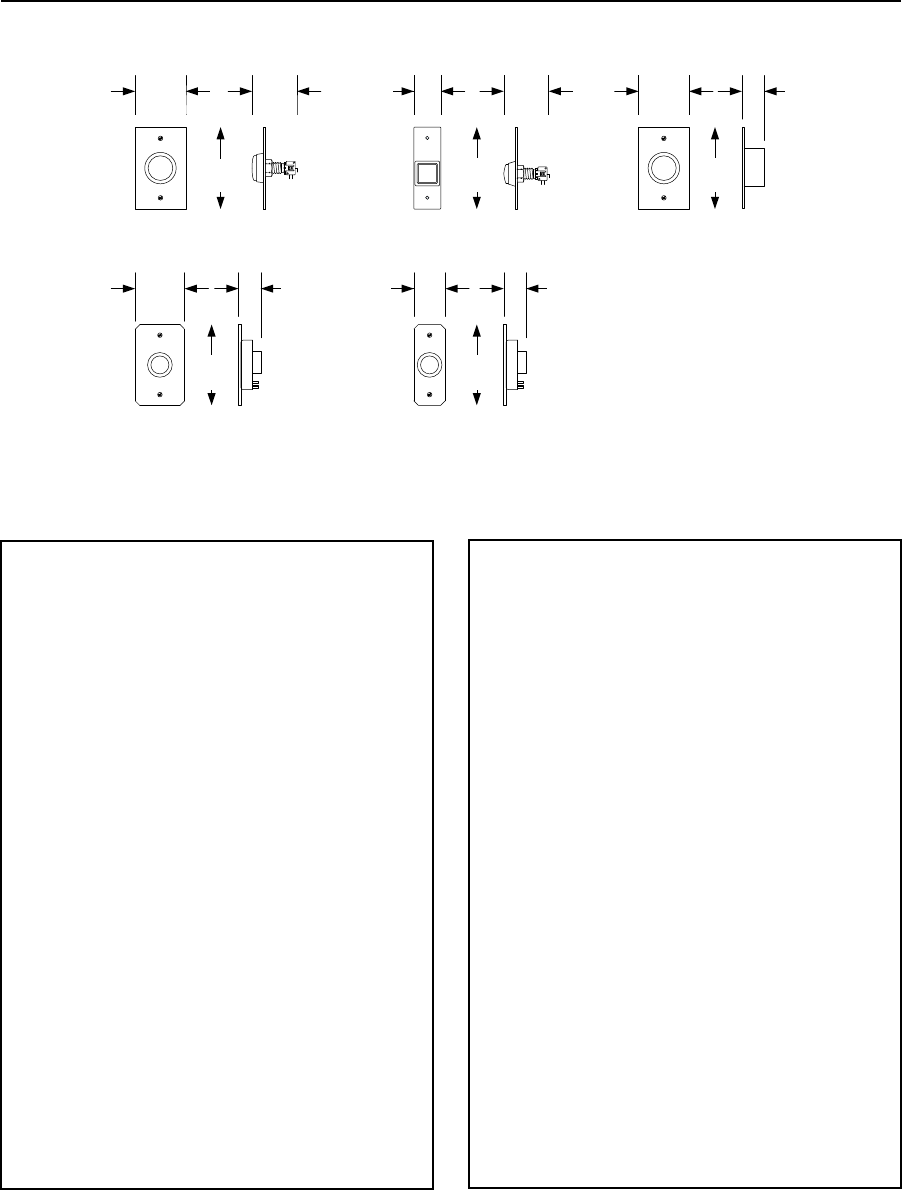
January 2019 PRICE SCHEDULE A 2.0
Access Control Devices
Prices and specifications subject to change without notice. Page 19
Push Buttons
2.75
1211-090
EXIT
PUSH TO
1211-091
1.75
EXIT
1211-083
1.25
No
Touch
EXIT
1211-080
2.81
4.56
2.50
EXIT EXIT
1.50
1211-081
71 mm
116 mm
63 mm
4.56
116 mm
38 mm
2.50
63 mm
2.81
71 mm
4.56
116 mm
32 mm
70 mm
4.50
114 mm
1.25
32 mm
4.50
114 mm
1.25
32 mm
44 mm
Push Button Switch
1211-080 ........................................................................ 62.62
• Stainless steel faceplate.
• Mounts in single-gang electric box.
• Requires 12-VDC power to illuminate exit button.
• Indoor use only.
1211-081 ........................................................................ 57.80
• Stainless steel faceplate.
• Mullion mount.
• Requires 12-VDC power to illuminate exit button.
• Indoor use only.
1211-083 ...................................................................... 108.00
• No Touch exit button.
• Stainless steel faceplate.
• Mounts in single-gang electric box.
• Requires 12-VDC power.
• Indoor use only.
Piezoelectric Switch
1211-090 ...................................................................... 360.00
• Vandal resistant stainless steel faceplate.
• Selectable illumination status (red, green).
• Mounts in single-gang electric box.
• Requires 12-24 VDC power.
1211-091 ...................................................................... 360.00
• Vandal resistant stainless steel faceplate.
• Selectable illumination status (red, green).
• Mullion mount.
• Requires 12-24 VDC power.
Page Rev 1/2/19

PRICE SCHEDULE A 2.0
Access Control Devices January 2019
Page 20 Prices and specifications subject to change without notice.
Lock Boxes
1402-080
5.00
6.50
2.38
4.50
1401-080
5.38
4.50 3.63
5.38
1400-080
POSTAL
LOCK BOX
FIRE
DEPT
FIRE
DEPT
114 mm 92 mm
136 mm
114 mm
5.38
136 mm
136 mm
127 mm 60 mm
165 mm
Fire Department Lock Box
1400-080.......................................................................122.00
• Accepts Fire Department padlock.
• Surface or post mounted.
• Painted bright red.
• Constant contact switch when padlock is removed and
the door is open.
1401-080.......................................................................122.00
• Accepts Knox 3501 key switch.
• Surface or post mounted.
• Faceplate painted bright red.
Postal Service Lock Box
1402-080 ...................................................................... 132.00
• Accepts standard postal key lock.
• Surface or post mount.
• Painted Postal blue.
• Postal lock can be installed to either activate a door or
gate, or simply open the postal box.
Page Rev 1/2/19

January 2019 PRICE SCHEDULE A 2.0
Access Control Devices
Prices and specifications subject to change without notice. Page 21
Replacement Components
Electronic Components
Page Rev 1/2/19
LED Light Kits
1804-701 ........................................................................ 24.08
Use with 1209, 1504, 1506
1804-705 ........................................................................ 24.08
Use with 1520 and lighted card readers
1804-706 ........................................................................ 24.08
Use with 1503
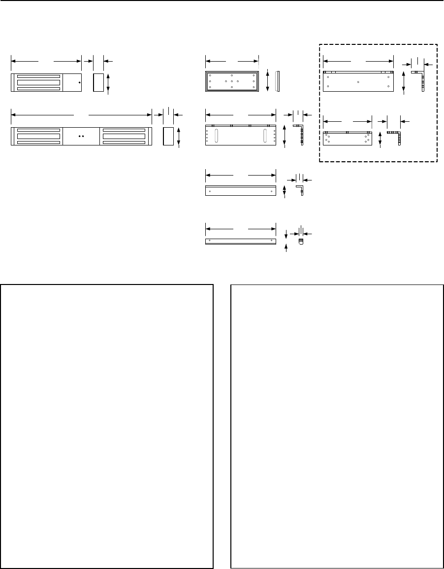
PRICE SCHEDULE A 2.0
Access Control Devices January 2019
Page 22 Prices and specifications subject to change without notice.
Magnetic Door Locks
1200 Lb (544 Kg) Door Locks
10.50 1.56
2.63 BO1-S12
BO2-S12
BO4-S12S6
BO5-S12S6
7.88
10.50
DKML-S12-1
10.50
10.50
1.50
1.00
0.56
3.00
3.00
1.50
0.75
BO3-S12
10.50
7.25
1.88
2.00
3.00
2.00
267 mm
67 mm
40 mm
21.00
533 mm
1.56
40 mm
2.63
67 mm
DKML-S12-2
267 mm
200 mm 76 mm
76 mm
38 mm
267 mm
25 mm
38 mm
267 mm
19 mm
14 mm
267 mm
76 mm
48 mm
184 mm 51 mm
51 mm
Single Door Locks Surface Mount
DKML-S12-1 .................................................................. 374.00
DKML-S12-1L ................................................................ 462.00
DKML-S12-1LT .............................................................. 490.00
Dual Door Locks Surface Mount
DKML-S12-2 .................................................................. 732.00
DKML-S12-2L ................................................................ 912.00
DKML-S12-2LT .............................................................. 958.00
• Locks operate on 12 or 24 Volt DC power.
• “L” includes LED status indicator.
• “T” includes built-in time delay.
Mounting Brackets
BO1-S12 Armature Bracket ............................................ 57.80
BO2-S12 L Bracket .......................................................... 57.80
BO4-S12S6 Angle Bracket .............................................. 64.22
BO5-S12S6 Spacer Bar ................................................... 51.96
BO3-S12 L & Z Bracket Kit ............................................ 142.00
Back-up Power Supply / Charger
1215-130 12/24 Volt @ 1 Amp .................................... 288.00
1215-131 12/24 Volt @ 2.5 Amp ................................. 494.00
1215-132 12/24 Volt @ 3 Amp .................................... 614.00
1215-133 12/24 Volt @ 6 Amp .................................... 890.00
• Requires two (2) 12 Volt, 7 Ah SLA batteries (not
included).
DC Lock Power Transformers
1812-020 12 Volt, 1000 mA ........................................... 51.62
1812-139 24 Volt, 500 mA ............................................. 55.56
Page Rev 1/2/19
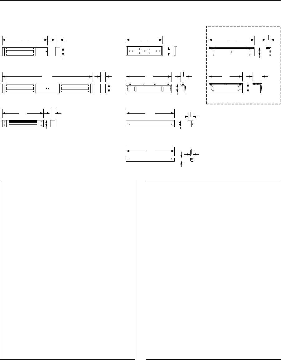
January 2019 PRICE SCHEDULE A 2.0
Access Control Devices
Prices and specifications subject to change without notice. Page 23
Magnetic Door Locks
600 Lb (272 Kg) Door Locks
9.88 1.06
1.88
19.69
BO3-S6
DKML-S6-1
DKML-S6-2
DKML-M6-1
9.00
1.50
9.88
BO1-S6
7.88 2.00
BO2-S6
9.88
1.13
1.88
251 mm
48 mm
27 mm
48 mm
500 mm
1.88
1.06
27 mm
500 mm
1.06
27 mm
38 mm
200 mm 54 mm
251 mm
BO4-S12S6
10.50
1.00
1.50
267 mm
25 mm
38 mm
48 mm
29 mm
BO5-S12S6
10.50
0.56
0.75
267 mm
19 mm
14 mm
7.25 2.00
2.00
184 mm 51 mm
51 mm
251 mm
48 mm
1.88
1.13
29 mm
Single Door Locks Surface Mount
DKML-S6-1 .................................................................... 344.00
DKML-S6-1L .................................................................. 384.00
DKML-S6-1LT ................................................................ 424.00
Single Door Locks Mortise Mount
DKML-M6-1 .................................................................. 284.00
DKML-M6-1L ................................................................. 310.00
DKML-M6-1LT ............................................................... 338.00
Dual Door Locks Surface Mount
DKML-S6-2 .................................................................... 670.00
DKML-S6-2L .................................................................. 758.00
DKML-S6-2LT ................................................................ 820.00
• Locks operate on 12 or 24 Volt DC power.
• “L” includes LED status indicator.
• “T” includes built-in time delay.
Mounting Brackets
BO1-S6 Armature Bracket .............................................. 57.80
BO2-S6 L Bracket ............................................................ 57.80
BO4-S12S6 Angle Bracket............................................... 64.22
BO5-S12S6 Spacer Bar.................................................... 51.96
BO3-S6 L & Z Bracket Kit .............................................. 142.00
Back-up Power Supply / Charger
1215-130 12/24 Volt @ 1 Amp .................................... 288.00
1215-131 12/24 Volt @ 2.5 Amp ................................. 494.00
1215-132 12/24 Volt @ 3 Amp .................................... 614.00
1215-133 12/24 Volt @ 6 Amp .................................... 890.00
• Requires two (2) 12 Volt, 7 Ah SLA batteries (not
included).
DC Lock Power Transformers
1812-020 12 Volt, 1000 mA ........................................... 51.62
1812-139 24 Volt, 500 mA ............................................. 55.56
Page Rev 1/2/19
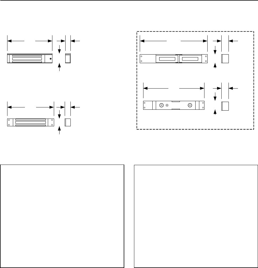
PRICE SCHEDULE A 2.0
Access Control Devices January 2019
Page 24 Prices and specifications subject to change without notice.
Magnetic Door Locks
300 Lb (136 Kg) Mini-locks and 2000 Lb (907 Kg) Shear Lock
10.66
9.69
1.13
1.38
DKSL-M20-1L
DKML-S3-1
DKML-M3-1
7.38 0.88
1.19
7.13 0.81
1.50
181 mm 21 mm
38 mm
181 mm 22 mm
30 mm
271 mm 29 mm
35 mm
246 mm
1.13
29 mm
1.38
35 mm
300 Lb. Door Locks
DKML-S3-1 Surface Mount ........................................... 286.00
DKML-M3-1 Mortise Mount ......................................... 286.00
2000 Lb. Shear Lock Surface Mount
DKSL-M20-1L ................................................................ 548.00
• Locks operate on 12 or 24 Volt DC power.
• Shear lock includes LED status indicator and built-in
signal relay.
Back-up Power Supply / Charger
1215-130 12/24 Volt @ 1 Amp..................................... 288.00
1215-131 12/24 Volt @ 2.5 Amp.................................. 494.00
1215-132 12/24 Volt @ 3 Amp..................................... 614.00
1215-133 12/24 Volt @ 6 Amp..................................... 890.00
• Requires two (2) 12 Volt, 7 Ah SLA batteries (not
included).
DC Lock Power Transformers
1812-020 12 Volt, 1000 mA............................................ 51.62
1812-139 24 Volt, 500 mA.............................................. 55.56
Page Rev 1/2/19
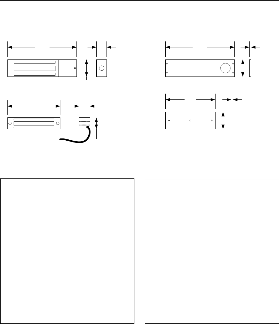
January 2019 PRICE SCHEDULE A 2.0
Access Control Devices
Prices and specifications subject to change without notice. Page 25
Magnetic Gate Locks
600 Lb (272 Kg) and 1200 Lb (544 Kg) Gate Locks
10.50
7.56
1216-080 / 1216-081
DKGL-S12-1 / DKGL-S12-1L 2.63
10.50
BO1-GL12
BO2-GL12
DKGL-S6-1
8.00
1.75
1.63
267 mm
1.56
2.63
67 mm
40 mm
267 mm 41 mm
44 mm
267 mm
0.25
67 mm
6 mm
192 mm
2.63
67 mm
0.25
6 mm
1200 Lb. Gate Lock Kits Surface Mount
1216-080 ...................................................................... 474.00
1216-081 ...................................................................... 560.00
• 1216-081 has built-in signal relay.
• Kits include predrilled and tapped mounting brackets,
BO1-GL12 and BO2-GL12.
1200 Lb. Gate Locks Top, Bottom or Face Mount
DKGL-S12-1 .................................................................. 396.00
DKGL-S12-1L w/Signal Relay ........................................ 486.00
600 Lb. Gate Lock Face Mount Only
DKGL-S6-1 w/Signal Relay ............................................ 368.00
• Gate locks operate on 12 or 24 Volt DC power.
Mounting Brackets
BO1-GL12 Lock Bracket .................................................. 80.26
BO2-GL12 Armature Bracket .......................................... 68.80
DC Lock Power Transformers - Regulated
1812-020 12 Volt, 1000 mA ............................................ 51.62
1812-139 24 Volt, 500 mA .............................................. 55.56
Page Rev 1/2/19
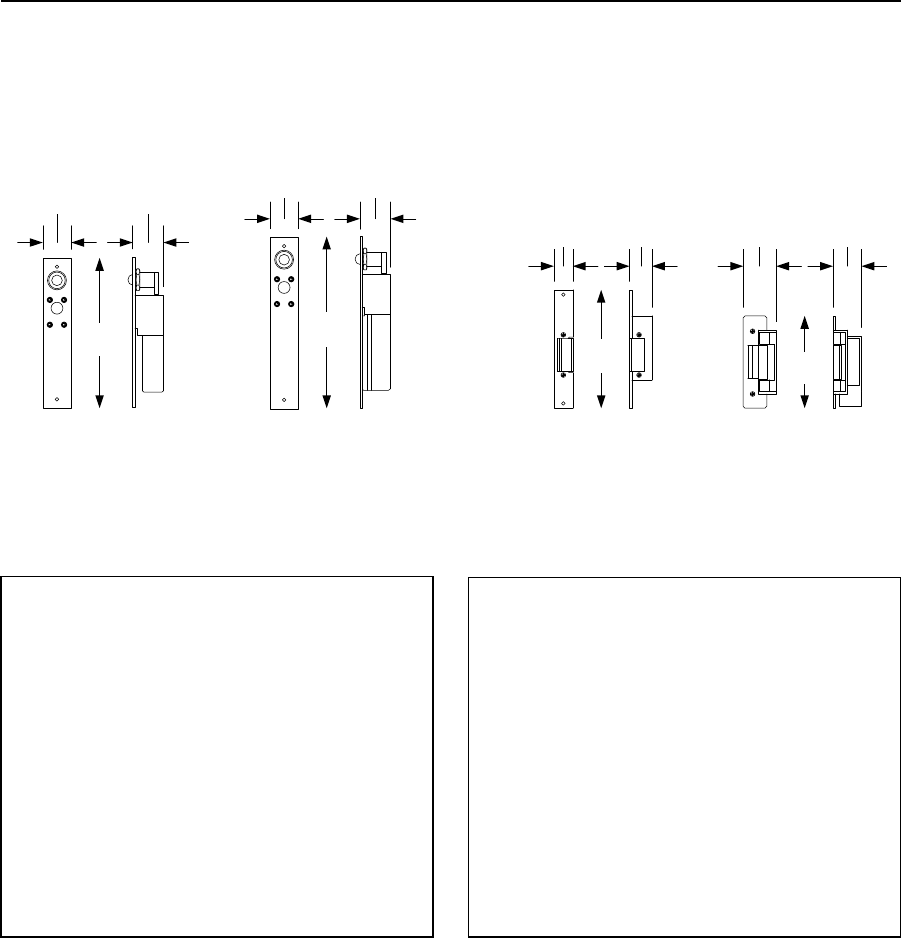
PRICE SCHEDULE A 2.0
Access Control Devices January 2019
Page 26 Prices and specifications subject to change without notice.
Electric Door Locks
Dead-bolts and Strikes
1.50
DKEB-M-1
7.94
1.63
9.06
DKEB-M-1L
DKEB-M-1D
DKEB-M-1LD
DKES-C1 DKES-C2
1.19 1.501.00 1.75
6.25 4.88
38 mm 41 mm
202 mm
1.63
41 mm
1.50
38 mm
230 mm
38 mm
44 mm25 mm 30 mm
159 mm 124 mm
Dead-bolt Door Locks
DKEB-M-1 ..................................................................... 404.00
DKEB-M-1L .................................................................... 424.00
DKEB-M-1D ................................................................... 424.00
DKEB-M-1LD ................................................................. 444.00
• “L” includes sensor to indicate locked or unlocked
condition.
• “D” includes door sensor to indicate an open or closed
door.
Electric Strikes 11/32 inch (8.74 mm) keeper
DKES-C1-1FX................................................................... 69.82
DKES-C1-1FS ................................................................... 72.24
Electric Strikes 20/32 inch (15.88 mm) keeper
DKES-C2-1FX................................................................... 86.68
DKES-C2-1FS ................................................................... 90.30
• FX = Fail Secure
• FS = Fail Safe
Page Rev 1/2/19
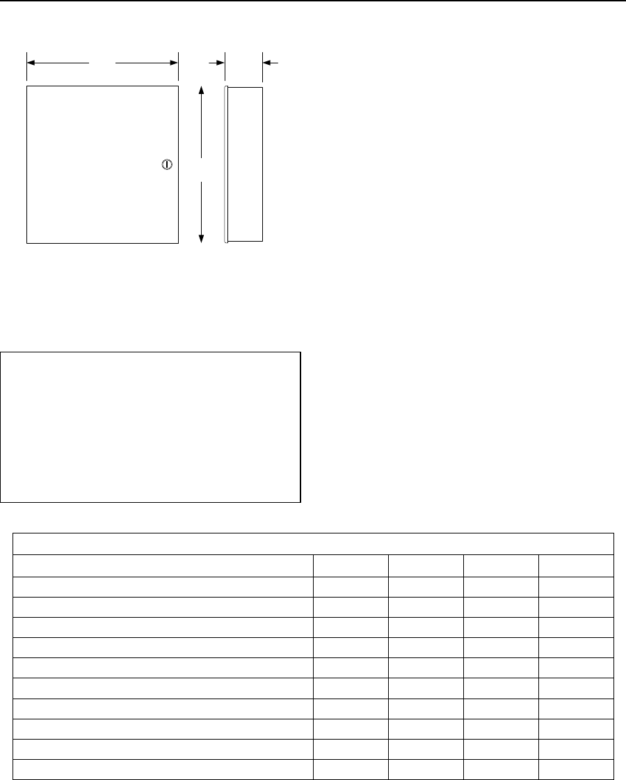
January 2019 PRICE SCHEDULE A 2.0
Access Control Devices
Prices and specifications subject to change without notice. Page 27
Magnetic Door Lock Power Supply
Power Supply / Battery Charger
13.00 3.25
13.50
343 mm
83 mm
330 mm
Magnetic Door Lock Power Supplies1
1215-130 12/24 Volt @ 1 Amp ..................................... 288.00
1215-131 12/24 Volt @ 2.5 Amp .................................. 494.00
1215-132 12/24 Volt @ 3 Amp ..................................... 614.00
1215-133 12/24 Volt @ 6 Amp ..................................... 890.00
• Requires two (2) 12 Volt, 7 Ah SLA batteries (not
included).
Agency Listings
Agency
1215-130
1215-131
1215-132
1215-133
UL 294 Access Control Systems
X
X
X
X
CSA C22.2 No. 205-M1983
X
X
X
X
MEA NYC Dept. of Building Safety
X
X
X
X
NFPA 101 Life Safety
X
UL 603 Burglar Alarm Systems
X
X
UL 1069 Hospital Signaling / Nurse Call Equipment
X
X
UL 1481 Power Supply for Fire Signaling Systems
X
X
X
CSFM California State Fire Marshall Approved
X
X
X
NFPA 72
X
X
X
FM Approved
X
X
Page Rev 1/2/19
PRICE SCHEDULE A 2.0
Access Control Devices January 2019
Page 28 Prices and specifications subject to change without notice.
Blank Page

January 2019 PRICE SCHEDULE A 2.0
Accessories
Prices and specifications subject to change without notice. Page 1
Section A4
This Price Schedule is effective January 7, 2019.
Accessories
Date Page Comment
1-2-19 All January, 2019 Price Schedule update.
PRICE SCHEDULE A 2.0
Accessories January 2019
Page 2 Prices and specifications subject to change without notice.
Page Rev 1/2/19
January 2019 PRICE SCHEDULE A 2.0
Accessories
Prices and specifications subject to change without notice. Page 3
Table of Contents
Mounting Posts
Standard & Heavy-Duty Posts ................................................................................................................................ 4
Designer Style Posts ............................................................................................................................................... 5
Kiosks ...................................................................................................................................................................... 6
Transformers
Transformer Box ..................................................................................................................................................... 7
Transformers .......................................................................................................................................................... 7
Surge Suppressers / Timers
Surge Suppressers .................................................................................................................................................. 8
7-Day Timer ............................................................................................................................................................ 8
Page Rev 1/2/19
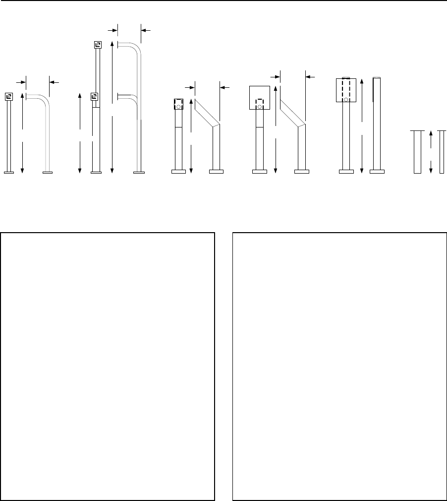
PRICE SCHEDULE A 2.0
Accessories January 2019
Page 4 Prices and specifications subject to change without notice.
Mounting Posts
Standard & Heavy-Duty Posts
14.00
41.75 49.00
14.00
1200-036 1200
-037
1200
-038
(not shown)1200-050
1200-051 (not shown)
45.00
13.00
74.00
45.00
1200-045
1200
-046 (not shown)1200-049 1200-056
1200
-057
1143 mm
330
mm
1143
mm
1880
mm
13.00
330
mm
53.00
24.00
1060 mm
356 mm
356 mm
1245
mm 1346 mm
610 mm
Standard Posts
1200-045 Pad Mount ................................................... 258.00
1200-046 In-Ground Mount ......................................... 258.00
1200-049 Dual Height Pad Mount................................ 542.00
• Standard posts are constructed from 2 x 2 (51 mm)
steel stock.
• In-ground mount posts do not have a baseplate and
extend an additional 24 inches (610 mm) in length.
In-Ground Adapter
1200-057 (use with 1200-045) ..................................... 228.00
• In-ground adapters provide a mount for posts with a
baseplate.
1802 Adapter Plate
1802-111 ...................................................................... 166.00
• Use this plate with when mounting 1802, 1802-EPD and
1819 systems to these posts.
Heavy-Duty Posts
1200-036 Pad Mount ................................................... 564.00
1200-037 Pad Mount ................................................... 602.00
1200-038 In-Ground Mount ......................................... 520.00
1200-050 Pad Mount ................................................... 496.00
1200-051 In-Ground Mount ......................................... 432.00
• Heavy-duty posts are constructed from 4 x 4 (102 mm)
steel stock.
• In-ground mount posts do not have a baseplate and
extend an additional 24 inches (610 mm) in length.
In-Ground Adapter
1200-056 (use with pad mount posts) ......................... 348.00
• In-ground adapters provide a mount for posts with a
baseplate.
Page Rev 1/2/19
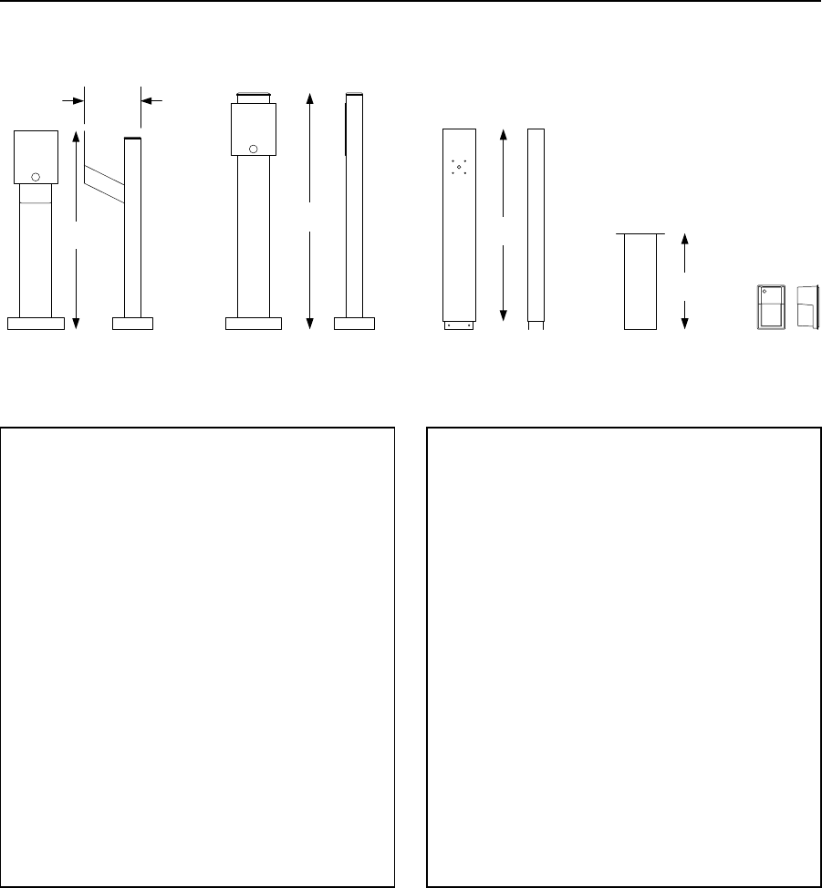
January 2019 PRICE SCHEDULE A 2.0
Accessories
Prices and specifications subject to change without notice. Page 5
Mounting Posts
Designer Style Mounting Posts
1200-0851200-086 1200-1501200-058
1200-087
59.00 48.00
24.00
49.50
14.00
1257 mm
356 mm
1499 mm
1219 mm
610 mm
Designer Style Posts
1200-085 Pad Mount .................................................. 1724.00
1200-086 Pad Mount .................................................. 1806.00
• Standard posts are constructed from 4 x 8 (102 mm x
203 mm) steel stock.
• Electrical compartment has four (4) accessory outlets
and room for surge suppressers and RF receiver.
In-Ground Adapter
1200-058 ...................................................................... 712.00
• In-ground adapters provide a mount for posts with a
baseplate.
1802 Adapter Plate
1802-111 ...................................................................... 166.00
• Use this plate with when mounting 1802, 1802-EPD and
1819 systems to these posts.
Accessories
1200-087 Light Tower Extension .................................. 700.00
1200-150 Light Assembly ............................................. 470.00
• Tower extension does not include light assembly.
• Fluorescent light with photocell for automatic dusk to
dawn operation.
Replacement Post Cap
1200-053 ...................................................................... 132.00
Page Rev 1/2/19
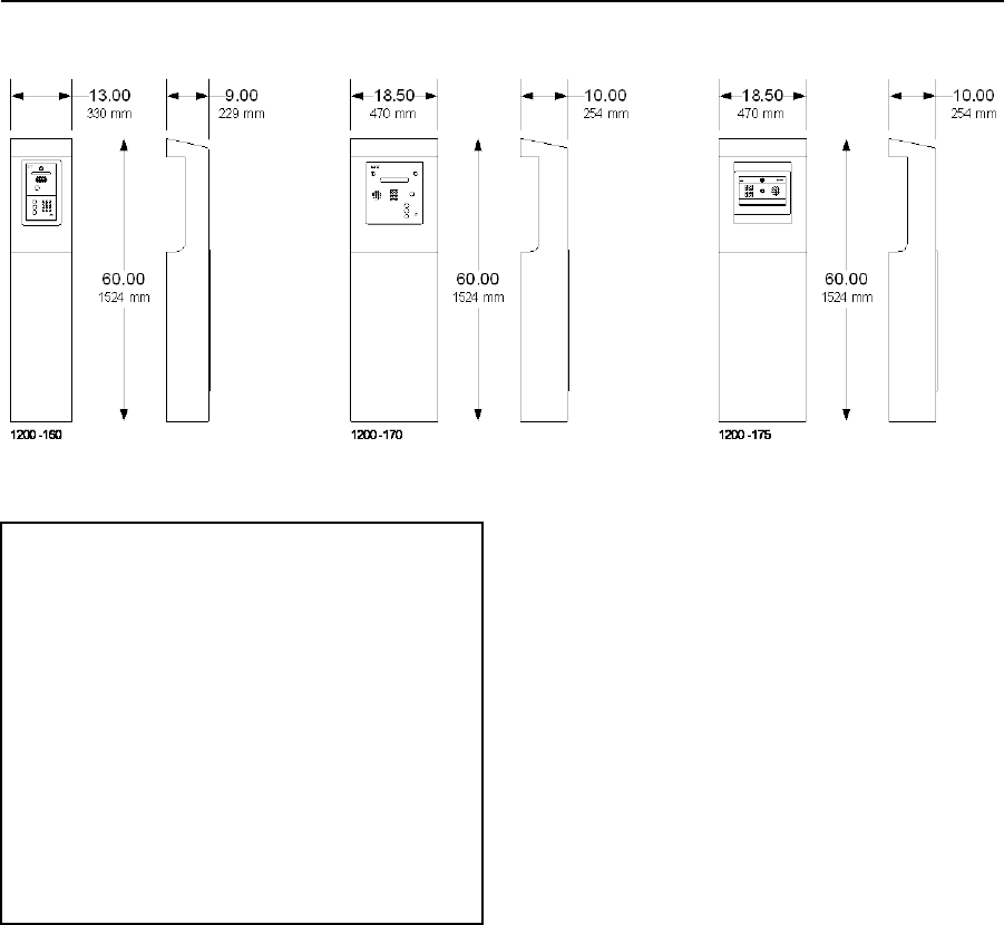
PRICE SCHEDULE A 2.0
Accessories January 2019
Page 6 Prices and specifications subject to change without notice.
Mounting Posts
Kiosks
Kiosk Style Posts1
1200-160 .................................................................... 4284.00
• Use with 1802 and 1802-EPD flush mount systems only.
1200-170 .................................................................... 4516.00
• Use with 1803, 1810, 1833, 1834, 1835 and 1837 flush
mount systems 80 Series systems only.
1200-175 .................................................................... 4516.00
• Use with 1812 Classic, 1812 Plus and 1812 Access Plus
flush mount systems only.
1. All kiosks include LED illumination and have an electrical compartment has four
(4) accessory outlets and room for surge suppressers and RF receiver.
Page Rev 1/2/19
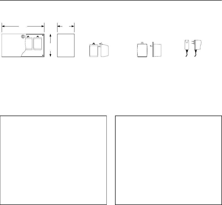
January 2019 PRICE SCHEDULE A 2.0
Accessories
Prices and specifications subject to change without notice. Page 7
Transformers
12, 16, 24 Volt AC & DC
11.13 4.50
6.00
20 VA Transformers
1215-061 12-Volt AC Output
1804-059 24-Volt AC Output
1804-060 16-Volt AC Output
40 VA Transformer
1508-060 16-Volt AC Output DC Transformers -Regulated
1812-020 12-Volt 1000 mA
1812-136 24-Volt 1000 mA
1200-080
152 mm
283 mm 114 mm
Transformer Box
1200-080 ...................................................................... 234.00
• Holds up to four (4) 20-VA transformers.
• Suitable for indoor or outdoor use.
20-VA Transformers
1215-061 12-VAC ........................................................... 45.16
1804-059 24-VAC ........................................................... 52.38
1804-060 16-VAC ........................................................... 52.38
40-VA Transformers
1508-060 16-VAC ........................................................... 57.80
DC Transformers - Regulated
1812-020 12-VDC, 1000 mA ........................................... 51.62
1812-136 24-VDC, 1000 mA ........................................... 64.22
Page Rev 1/2/19
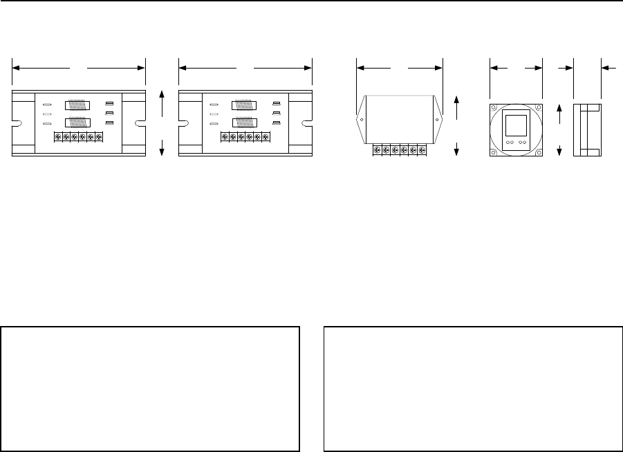
PRICE SCHEDULE A 2.0
Accessories January 2019
Page 8 Prices and specifications subject to change without notice.
Accessories
Timers / Surge Suppressers
6.00 6.00
3.00
3.88
2.75
2.37 1.25
2.37
152
MM 152 MM
76
MM 70 MM 60 MM
99 MM 60 MM 32 MM
1877-010 1878-010 1879-080 2600-791
Surge Suppressers
1877-010 Phone Line .................................................... 156.00
1878-010 Low Voltage (24 VAC) ................................... 156.00
1879-080 High Voltage (120 VAC)................................. 156.00
7-Day Timer
2600-791 ...................................................................... 254.00
• 20 Programs.
• 24 VAC.
• Form C dry contact relay.
Page Rev 1/2/19

January 2019 PRICE SCHEDULE A 2.0
Advanced Replacement & Repair
Prices and specifications subject to change without notice. Page 1
Section A5
This Price Schedule is effective January 7, 2019.
Advanced Replacement & Repair
Date Page Comment
1-2-19 All January, 2019 Price Schedule update.
PRICE SCHEDULE A 2.0 January 2019
Advanced Replacement & Repair
Page 2 Prices and specifications subject to change without notice.
Page Rev 1/2/19
January 2019 PRICE SCHEDULE A 2.0
Advanced Replacement & Repair
Prices and specifications subject to change without notice. Page 3
Table of Contents
Advance Replacement & Repair Policy ................................................................................................................... 5
Telephone Entry System Main Circuit Board Reference Table ............................................................................... 6
Telephone Entry System Circuit Boards ................................................................................................................. 8
Telephone Entry System Circuit Board Upgrades ................................................................................................. 10
Access Control Products Circuit Board Reference Table ...................................................................................... 11
Access Control Systems Major Components ........................................................................................................ 12
Access Control Products Circuit Boards ................................................................................................................ 13
Gate Operator Circuit Board Reference Table ...................................................................................................... 14
Gate Operator Circuit Boards ............................................................................................................................... 16
Counter and Accessory Boards ............................................................................................................................. 17
Loop Detectors ..................................................................................................................................................... 18
Page Rev 1/2/19
PRICE SCHEDULE A 2.0 January 2019
Advanced Replacement & Repair
Page 4 Prices and specifications subject to change without notice.
Page Rev 1/2/19

January 2019 PRICE SCHEDULE A 2.0
Advanced Replacement & Repair
Prices and specifications subject to change without notice. Page 5
Circuit Board Advance Replacement and Repair Policy
Repair and Return
All repairs must be issued an RMA number before they can be returned to DoorKing. Repairs that are returned without prior authorization
are subject to lengthy delays. Prior to returning any item to DoorKing, please contact our RMA department for an RMA number and have
the following information available: the model number of the product and the circuit board number, the serial number, and the revision
letter.
Standard flat rate repair charges that are listed on the following pages apply only to products manufactured by DoorKing that are beyond
the warranty period and became defective because of random component failure. Standard flat rate repair charges apply only to products
that are returned to DoorKing for repair and return. The standard flat rate repair charge does not apply to products that are returned
under an advance replacement RMA.
The standard repair charges do not apply to products or parts that are deemed by DoorKing to be un-repairable because of vandalism,
abuse, improper installation including connection to an improper voltage source, power surges, lightning damage or natural disasters.
Additional repair charges will be assessed to replace missing parts or parts damaged beyond repair. Boards that are deemed to be beyond
repair will be returned to the owner or scrapped upon written authorization from the owner.
Advance Replacements
Defective or un-used parts that have been advanced to you must be returned to DoorKing within thirty (30) days from the date of the
advance replacement invoice.
Not all circuit boards are available for advance replacement. Advance replacement boards are not guaranteed to be available. You must
know the serial number and the revision level of the board that you are requesting an advance replacement for prior to our shipping an
advance replacement board to you.
Out of warranty advance replacement repair charges are billed at a higher rate than the standard flat rate repair and return charge.
Obsolete Board Repair and Replacement (Upgrade) Information
Many early model circuit boards are not available for advance replacement and cannot be repaired. These boards are identified in the
tables on the following pages.
Upgrade: The upgrade option allows you to replace an old circuit board with a new current production circuit board at a reduced rate.
When choosing this option, the upgrade charge includes any additional parts required to install the new circuit board into the telephone
entry / access control system. The upgrade option also carries a two-year warranty on the circuit board.
If you choose the upgrade option as an advance replacement, the reduced rate upgrade charge will not be applicable until the replaced
circuit board and memory chips are returned to DoorKing. Otherwise, you will be responsible for payment in full of the new circuit board
and memory chips sent to you under the advance replacement program.
Shipping Charges
DoorKing pays UPS ground shipping charges one way only on warranty advance replacement items. If any other means of shipping (UPS
red, blue, etc.) is requested, you are responsible for the difference between that method and UPS ground charges. Shipping charges for
the return of advance replacement items are the responsibility of the customer. All shipping charges for non-warranty repair items are the
responsibility of the customer.
Repair Warranty
Circuit boards repaired by DoorKing are warranted for a period of ninety (90) days from the date of repair. This warranty covers bench
repairs only. For this warranty to be in effect, any product or parts must be returned to DoorKing freight prepaid. DoorKing is not
responsible for any cost incurred involving on site service calls, or labor charges incurred in the removal or replacement of any parts. This
warranty does not apply to products or parts damaged because of vandalism, abuse, improper installation including connection to an
improper voltage source, power surges, lightning damage or natural disasters.
Page Rev 1/2/19

PRICE SCHEDULE A 2.0 January 2019
Advanced Replacement & Repair
Page 6 Prices and specifications subject to change without notice.
Telephone Entry System Circuit Boards
Circuit
Board
Model(s)
Used On REV
Options Available
Notes
Repair Advance Replace
1800-009
1800-010
1801-010
1800-081
1800-080
1801-080
All Yes Yes Yes Cellular system circuit boards.
1802-010
1802, 1804-1
1808, 1810-1
All No No No No upgrade available.
1804-010
1803-2, 1804-2
1810-2
All No No No No upgrade available.
1833-010 1833 D – R No No
Upgrade
Schedule K
Use upgrade option.
1833-010 1833 S or Higher Yes Yes
Upgrade K replaces board with the most current
level board revision.
1834-010 1834 D - Q No No
Upgrade
Schedule K
Use upgrade option.
1834-010 1834 R or Higher Yes Yes
1834-009
1834 Wall Mount
Only
D - Q No No
Upgrade
Schedule K
Use upgrade option.
1834-009
1834 Wall Mount
1834 90 Series
R or Higher Yes Yes
Upgrade K replaces board with the most current
level board revision.
1835-010 1835 D – R No No
Upgrade
Schedule K
Use upgrade option.
1835-010 1835 S or Higher Yes Yes
Upgrade K replaces board with the most current
level board revision.
1835-009
1835 Wall Mount
Only
D – Q No No
Upgrade
Schedule K
Use upgrade option.
1835-009
1835 Wall Mount
1835 90 Series
R or Higher Yes Yes
Upgrade K replaces board with the most current
level board revision.
1837-010 1837 D – R No No
Upgrade
Schedule K
Use upgrade option.
1837-010 1837 S or Higher Yes Yes
Upgrade K replaces board with the most current
level board revision.
1840-010 1815 All No No
Upgrade
Schedule A
Use upgrade option.
1841-010 1817 All No No No No upgrade available.
1842-010 1818 All No No
Upgrade
Schedule C
Use upgrade option.
1843-010 1814 All No No
Upgrade
Schedule D
Use upgrade option.
1844-010 1803 PC All No No
Upgrade
Schedule I
Use upgrade option.
1850-010 1814 A - I No No No No upgrade available.
1850-010 1814 J – R No No
Upgrade
Schedule D
Use upgrade option.
1851-010 1814 P All No No
Upgrade
Schedule D
Use upgrade option.
1852-010 1815 All No No
Upgrade
Schedule A
Use upgrade option.
1853-010 1817 All No No
Upgrade
Schedule B
No upgrade available.
1854-010 1818 All No No
Upgrade
Schedule C
Use upgrade option.
1855-010 1815 All No No
Upgrade
Schedule A
Use upgrade option.
1856-010 1817 All No No
Upgrade
Schedule B
No upgrade available.
1857-010 1818 All No No
Upgrade
Schedule C
Use upgrade option.
1860-010
1802, 1803-1
1804-1, 1808
1810-1
All No No Upgrade
Schedule E Use upgrade option.
Page Rev 1/2/19

January 2019 PRICE SCHEDULE A 2.0
Advanced Replacement & Repair
Prices and specifications subject to change without notice. Page 7
Telephone Entry System Circuit Boards
Circuit
Board
Model(s)
Used On REV
Options Available
Notes
Repair Advance Replace
1862-010
1802, 1803
1808, 1810
A - M No No
Upgrade
Schedule N
Use upgrade option.
1862-010
1802, 1803
1808, 1810
N or Higher Yes Yes
1863-010
1802P, 1803P
1808P, 1810P
A - H No No
1863-010
1802P, 1803P
1808P, 1810P
I or Higher Yes Yes
1865-010
1803-2, 1804-2
1810-2
All No No
Upgrade
Schedule F
Use upgrade option.
1870-010 1812 All No No
Upgrade
Schedule H
Use upgrade option.
1871-010 1812 A – Z No No
Upgrade
Schedule J
Use upgrade option.
1871-010 1812 AA - Higher Yes Yes
1880-010 1816 All No No No
1885-010 1816 / 1820 H - R No No
1885-010 1816 / 1820 S - Higher Yes Yes
1971-010 1812 Plus
A – N
O - Higher
Yes
Yes
No
Yes
1970-010
1802AP,1808AP, 1810AP,
1812AP, 1838AP
A –N
O - Higher
Yes
Yes
No
Yes
1597-010 1814-075 All No No Yes Secondary keypad board. Replace if faulty.
1598-010 All All No No Yes
Secondary keypad interface board. Replace if
faulty.
1807-010
1803, 1804
1810
All No No No
Old style programming display. No replacement
available.
1875-010 1812 All No Yes Yes By-pass switch. Replace if faulty.
1881-010 1816 D - F No No 1816 decoder board.
1881-010 1816 G - Higher Yes Yes 1816 decoder board.
1882-010 1816 All No No No 1816 relay board.
1884-010 1820 All Yes Yes 1820 Line Interface Board
1886-010 1820 All Yes Yes 1820 Power Supply Board
1890-010 1802, 1803, 1810 All Yes Yes Programming display for 1862 board.
1896-010 1814 All No No No Old style small directory. No replacement available.
1897-010 All All No No No Microphone board. Replace with 1998-010 if faulty.
1982-010 1816 All Yes Yes 1816 relay board
1998-010 All All No Yes Yes Microphone board. Replace if faulty.
1898-010
1803, 1804
1810
All No No No
Vacuum fluorescent programming display. No
replacement available.
1899-010 1704, 1720, 1804 All No No No Fluorescent light kit ballast assembly.
2348-010
1833, 1835
1837, 1838
A-C No No Elevator control board.
2348-010
1833, 1835
1837, 1838
D - Higher Yes Yes Elevator control board.
2351-010
1833, 1835
1837, 1838
All No No Tracker expansion board - Obsolete
2354-010 RS-485 Devices All Yes Yes RS-485 Wiegand Interface Board
2358-010 1833, 1835 1837, 1838 All Yes Yes Tracker expansion board
2360-010
1833, 1835
1837, 1838
All Yes Yes Wireless baseboard
1489-010 2358-010 All Yes Yes Wireless expansion board
2366-010 All Yes Yes Wireless repeater
Page Rev 1/2/19

PRICE SCHEDULE A 2.0 January 2019
Advanced Replacement & Repair
Page 8 Prices and specifications subject to change without notice.
Telephone Entry System Circuit Boards
1800 Series Boards
Code
Description
List
Repair A
1801-010 Repair and return only.
240.00
1830 Series Boards
Repair A
XCHG A
1833-010 Repair and return.
1833-010 Advance replacement.
240.00
320.00
Repair A
XCHG A
1834-010 Repair and return.
1834-010 Advance replacement.
240.00
320.00
Repair A
XCHG A
1834-009 Repair and return.
1834-009 Advance replacement.
240.00
320.00
Repair A
XCHG A
1835-010 Repair and return.
1835-010 Advance replacement.
240.00
320.00
Repair A
XCHG A
1835-009 Repair and return.
1835-009 Advance replacement.
240.00
320.00
Repair A
XCHG A
1837-010 Repair and return.
1837-010 Advance replacement.
240.00
320.00
Repair A
XCHG A
1838-010 Repair and return.
1838-010 Advance replacement.
240.00
320.00
1860 Series Boards
Repair A
XCHG A
1862-010 Repair and return.
1862-010 Advance replacement.
240.00
320.00
Repair A
XCHG A
1863-010 Repair and return.
1863-010 Advance replacement.
240.00
320.00
1870 Series Boards
Repair A
XCHG A
1871-010 Repair and return.
1871-010 Advance replacement.
240.00
320.00
1880 Series Boards
Repair A
1881-010 Repair and return.
240.00
Repair D
1882-010 Repair and return.
140.00
Repair D
XCHG D
1884-010 Repair and return.
1884-010 Advance replacement.
140.00
180.00
Repair A
XCHG A
1885-010 Repair and return.
1885-010 Advance replacement.
240.00
320.00
Repair D
XCHG D
1982-010 Repair and return.
1982-010 Advance replacement.
140.00
180.00
Page Rev 1/2/19

January 2019 PRICE SCHEDULE A 2.0
Advanced Replacement & Repair
Prices and specifications subject to change without notice. Page 9
Telephone Entry System Miscellaneous Boards
1890 Series Boards
Code
Description
List
Repair E
XCHG E
1890-010 Repair and return.
1890-010 Advance replacement.
80.00
100.00
Repair E
1896-010 Repair and return only.
80.00
2300 Series Boards
Repair A
XCHG A
2348-010 Repair and return.
2348-010 Advance replacement.
240.00
320.00
Miscellaneous Boards
Repair E
1807-010 Repair and return only.
80.00
XCHG G
1875-010 Replacement only.
95.00
Keypads
XCHGKP01
1804-055, 1804-056, 1805-155, 1804-156 Replacement only.
121.50
XCHGKP02
1895-016, 1895-017 Replacement only.
104.00
Page Rev 1/2/19

PRICE SCHEDULE A 2.0 January 2019
Advanced Replacement & Repair
Page 10 Prices and specifications subject to change without notice.
Telephone Entry System Circuit Board Upgrades
1830 Series Upgrade
Code
Description
List
Upgrade M
1834 to 1835 Upgrade
Replaces 1834 circuit board with the 1835 circuit board. Memory chip included.
1300.00
Upgrade K
1833, 1834, 1835, 1837, 1838 Board Upgrade
Replaces older 1830 series circuit board with current 1830 series circuit board. Memory
chips (same size) included.
1300.00
1850 / 1840 Series Board Upgrades
Upgrade A
1852, 1855, 1840 Board Upgrade
Replaces 1852, 1855 or 1840 circuit board (1815 systems) with 1835 circuit board.
Software and memory chips (same size) included.
1300.00
Upgrade C
1854, 1857, 1842 Board Upgrade
Replaces 1854, 1857 or 1842 circuit board (1818 systems) with 1838 circuit board.
Software and memory chips (same size) included.
1300.00
Upgrade D
1850, 1851, 1843 Board Upgrade
Replaces 1850, 1851 or 1843 circuit board (1814 systems) with 1834 circuit board.
Software and memory chips (same size) included.
1300.00
Upgrade I
1844 Board Upgrade
Replaces 1844 circuit board (1803 PC systems) with 1833 circuit board. Software and
memory chips (same size) included.
1300.00
1860 Series Board Upgrades
Upgrade E
1860 Board Upgrade
Replaces 1860 circuit board with 1862 circuit board. Includes display & memory chips of
same size as those in board being upgraded.
670.00
Upgrade F
1865 Board Upgrade
Replaces 1865 circuit board with 1862 circuit board. Includes display, terminal strip &
memory chips of same size as those in board being upgraded.
638.00
Upgrade N
1862 Board Upgrade
Replaces older 1862 circuit board with current 1862 circuit board. Includes display,
terminal strip & memory chips of same size as those in board being upgraded.
670.00
1870 Series Board Upgrades
Upgrade H
1870 Board Upgrade
Replaces 1870 circuit board with 1871 circuit board. Includes 1812-075 conversion kit.
976.00
Upgrade J
1871 Board Upgrade
Replaces 1871 Rev A – Z circuit board with current 1871 circuit board.
866.00
1970 Series Board Upgrades
Upgrade J
1970 Board Upgrade
Replaces 1970 Rev A – K3 circuit board with current 1970 circuit board.
866.00
Upgrade J
1971 Board Upgrade
Replaces 1971 Rev A – K3 circuit board with current 1971 circuit board.
866.00
Page Rev 1/2/19

January 2019 PRICE SCHEDULE A 2.0
Advanced Replacement & Repair
Prices and specifications subject to change without notice. Page 11
Access Control Products Circuit Boards
Circuit
Board
Model(s)
Used On REV
Options Available
Notes
Repair Advance Replace
1500-009
Wiegand
Keypads
All No No 1515-009 New circuit board.
1500-010 1503, 1504 All No No 1515-010 New circuit board.
1502-010 1502, 1504 All No No 1515-010 New circuit board.
1503-010 1503, 1504 All No No 1515-010 New circuit board.
1505-009 1520 A - D No No
1505-009 1520 E – Higher Yes Yes
1506-010 1506, 1504 A – K No No No
1506-010 1506, 1504 L – Higher Yes Yes
1508-010 1508 All No No No
1513-010 1513 A – D Yes No
1513-010 1513 E – Higher Yes Yes
1515-009
Wiegand
Keypads
All Yes Yes Yes
1515-010 1515 All Yes Yes
1587-010 Printer Interface All No No Yes Replace if faulty.
1588-010 1508 All No No No
1589-010 1508 All No No No
1596-010 1507, 1514 All No No No
1597-010
Secondary
Keypad Interface
All No No Yes Replace if faulty.
1599-010 1506, 1504 F - Higher No No Yes Replace if faulty.
1838-010 1838 A – Q No No
Upgrade
Schedule K
Use upgrade option.
1838-010 1838 R or Higher Yes Yes
Upgrade
Schedule K
Upgrade K replaces board with the most current
level board revision.
1842-010 1818 All No No
Upgrade
Schedule C
Use upgrade option.
1854-010 1818 All No No
Upgrade
Schedule C
Use upgrade option.
1857-010 1818 All No No
Upgrade
Schedule C
Use upgrade option.
2348-010 Elevator Control A - C Yes No Yes
2348-010 Elevator Control D – Higher Yes Yes Yes
2351-010
Tracker
Expansion
All No No Yes Replace with 2358-010 tracker board
2354-010 RS-485 Devices E - F Yes No RS-485 Wiegand Interface Board
2354-010 RS-485 Devices G - Higher Yes Yes RS-485 Wiegand Interface Board
2358-010
Tracker
Expansion
All Yes Yes
8040-080 8040 All Yes Yes
8054-xxx 8054 All Yes Yes
8055-xxx 8055 All Yes Yes
8056-xxx 8056 All No No Replace with 8040 receiver
8057-xxx 8057 All Yes Yes
8059-xxx 8059 All No No Replace with 8040 receiver
Page Rev 1/2/19

PRICE SCHEDULE A 2.0 January 2019
Advanced Replacement & Repair
Page 12 Prices and specifications subject to change without notice.
Access Systems Major Components
Circuit
Board
Model(s)
Used On REV
Options Available
Notes
Repair Advance Replace
1894-040
Color CCTV
Camera
All Yes
Cameras are sent to the vendor for warranty repair /
replacement.
1812-145
Color CCTV
Camera
All Yes
1812-147
Color CCTV
Camera
All Yes
Page Rev 1/2/19

January 2019 PRICE SCHEDULE A 2.0
Advanced Replacement & Repair
Prices and specifications subject to change without notice. Page 13
Access Control System Circuit Boards
1500 Series Boards
Code
Description
List
Repair D
XCHG D
1515-010 Repair and return.
1515-010 Advance replacement.
140.00
180.00
Repair D
XCHG D
1506-010 Repair and return.
1506-010 Advance replacement.
140.00
180.00
Repair D
XCHG D
1513-010 Repair and return.
1513-010 Advance replacement.
140.00
180.00
Repair D
XCHG D
1505-009 Repair and return.
1505-009 Advance replacement.
140.00
180.00
1800 Series Boards
Repair A
XCHG A
1838-010 Repair and return.
1838-010 Advance replacement.
240.00
320.00
2300 Series Boards
Repair A
XCHG A
2348-010 Repair and return.
2348-010 Advance replacement.
240.00
320.00
Repair D
XCHG D
2354-010 Repair and return.
2354-010 Advance replacement.
140.00
180.00
Repair D
XCHG D
2358-010 Repair and return.
2358-010 Advance replacement.
140.00
180.00
Page Rev 1/2/19

PRICE SCHEDULE A 2.0 January 2019
Advanced Replacement & Repair
Page 14 Prices and specifications subject to change without notice.
Gate Operator Circuit Boards
Circuit
Board
Model(s)
Used On REV
Options Available
Notes
Repair Advance Replace
1473-010
Pre-2016
operators only
All Yes Yes Replaces 2340 circuit board. Use Kit P/N 1473-121.
1601-010 1601 D - Y No No Yes Replace with current production board.
1601-010 1601, 1602
Z - AH -
Higher
Yes Yes
2340-010
1601, 1602, 1603,
6100, 6300, 9150,
9300, 9310
All No No Replace with 1473-121 board kit.
2355-010 1000 A - J No No Replace with current production board.
2355-010 1000 K - Higher Yes Yes Yes Model 1000 Inverter circuit board.
4001-010
240, 480, 600, 800,
1000
All No No Yes Replace with new 4502-009 board.
4100-010 6524, 9024 AA - AF Yes Yes Replace with 4100-018.
4100-012 6524, 9024 H - O Yes Yes Use with Pre 2016 models only.
4100-018 6524, 9024 All Yes Yes
4201-010
605, 805 mfg. prior
to 6/93
All No No Yes
Replace with new 4502-009 board (requires 4001-
020 terminal strip and rewire).
4302-010
6002, 6003, 6004,
6400
AA - AC Yes Yes Replace with 4302-018
4302-012
6002, 6003, 6004,
6005, 6400
D - M No No Use with pre 2016 models only.
4302-012
6002, 6003, 6004,
6005, 6400
N or
Higher
Yes Yes Use with Pre 2016 models only.
4302-018
6003, 6004, 6005,
6400
All Yes Yes Yes
4402-012 1150, 9200, 9300 B - H No No Use with pre 2016 models only.
4402-012 1150, 9200, 9300 I or Higher Yes Yes Use with pre 2016 models only.
4403-012 9310 C - N No No Use with pre 2016 models only.
4403-012 9310
M or
Higher
Yes Yes Use with pre 2016 models only.
4404-010
9210, 9220 9230,
9235, 9240, 9530
9550, 9555, 9575
AA - AB Yes Yes Replace with 4404-018.
4404-012
9210, 9220 9230,
9235, 9240, 9530
9550, 9555, 9575
B - E No No Use with Pre 2016 models only.
4404-012
9210, 9220 9230,
9235, 9240, 9530
9550, 9555, 9575
F or
Higher Yes Yes Use with Pre 2016 models only.
4404-018
9210, 9220 9230,
9235, 9240, 9530
9550, 9555, 9575
All Yes Yes
4405-010 6500, 6550, 9000 AA - AB Yes Yes Replace with 4405-018.
4405-012
1175, 6500, 6550,
9000
A - F No NO Use with Pre 2016 models only.
4405-012
1175, 6500, 6550,
9000
G - Higher Yes Yes Use with Pre 2016 models only.
4405-018
1175, 6500, 6550,
9000
All Yes Yes
Page Rev 1/2/19

January 2019 PRICE SCHEDULE A 2.0
Advanced Replacement & Repair
Prices and specifications subject to change without notice. Page 15
Gate Operator Circuit Boards
Circuit
Board
Model(s)
Used On REV
Options Available
Notes
Repair Advance Replace
4501-010
240, 480, 600,
601, 602, 605,610,
615, 620, 625, 805,
810, 815
All No No Replace with 4502-009.
4502-009
240, 480, 600,
601, 602, 605,610,
615, 620, 625, 805,
810, 815
N - Higher Yes Yes
4502-010 6050, 6100, 6300 AA - AC Yes Yes Replace with 4502-018.
4502-012 6050, 6100, 6300 A - J No No Use with Pre 2016 models only.
4502-012 6050, 6100, 6300
K or
Higher
Yes Yes Use with Pre 2016 models only.
4502-018 6050, 6100, 6300 All Yes Yes
4601-010
910, 915, 920,
1100
All No No Replace with 4602-009.
4602-009
910, 915, 920,
1100
S - Higher Yes Yes
4602-010 9100, 9150 AA - AB Yes Yes Replace with 4602-018.
4602-012 9100, 9150 A - Q No No Use with Pre 2016 models only.
4602-012 9100, 9150
R or
Higher
Yes Yes Use with Pre 2016 models only.
4602-018 9100, 9150 All Yes Yes
4701-010 905, 907 All No No Replace with 4702-009.
4702-009 905, 907 J - Higher Yes Yes
4702-010 9050, 9070 AA - AB Yes Yes Replace with 4702-018.
4702-012 9050, 9070 A - H No No Use with pre 2016 models only.
4702-012 9050, 9070 I or Higher Yes Yes Use with pre 2016 models only.
4702-018 9050 All Yes Yes
Page Rev 1/2/19

PRICE SCHEDULE A 2.0 January 2019
Advanced Replacement & Repair
Page 16 Prices and specifications subject to change without notice.
Gate Operator Circuit Boards
Swing Gate Operators
Code
Description
List
Repair A
XCHG A
4302 All boards - Repair and return.
4302 All boards - Advance replacement.
240.00
320.00
Repair A
XCHG A
4405 All boards - Repair and return.
4405 All boards - Advance replacement (Rev M and higher only).
240.00
320.00
Repair A
XCHG A
4502 All boards - Repair and return.
4502 All boards - Advance replacement.
240.00
320.00
Slide Gate Operators
Repair A
XCHG A
4402 All boards - Repair and return.
4402 All boards - Advance replacement.
240.00
320.00
Repair A
XCHG A
4403 All boards - Repair and return.
4403 All boards - Advance replacement.
240.00
320.00
Repair A
XCHG A
4404 All boards - Repair and return.
4404 All boards - Advance replacement.
240.00
320.00
Repair A
XCHG A
4602 All boards - Repair and return.
4602 All boards - Advance replacement.
240.00
320.00
Repair A
XCHG A
4702 All boards - Repair and return.
4702 All boards - Advance replacement.
240.00
320.00
Barrier and Overhead Gate Operators
Repair A
XCHG A
1601 All boards - Repair and return.
1601 All boards - Advance replacement (Rev W and higher only).
240.00
320.00
Repair A
XCHG A
4402 All boards (1150 operator) - Repair and return.
4402 All boards (1150 operator) - Advance replacement.
240.00
320.00
Repair A
XCHG A
4405 All boards (1175 operator) - Repair and return.
4405 All boards (1175 operator) - Advance replacement.
240.00
320.00
Power Inverter / Backup
Repair D
XCHG D
2355-010 Repair and return.
2355-010 Advance replacement (Rev W and higher only).
140.00
180.00
Page Rev 1/2/19

January 2019 PRICE SCHEDULE A 2.0
Advanced Replacement & Repair
Prices and specifications subject to change without notice. Page 17
Counter and Accessory Boards
Magnetic Counter Boards
Repair E
XCHG E
3003-010 Repair and return.
3003-010 Advance replacement.
80.00
100.00
Repair E
XCHG E
3003-012 Repair and return.
3003-012 Advance replacement.
80.00
100.00
Repair E
XCHG E
3003-013 Repair and return.
3003-013 Advance replacement.
80.00
100.00
Repair E
XCHG E
3003-014 Repair and return.
3003-014 Advance replacement.
80.00
100.00
Repair E
XCHG E
3003-015 Repair and return.
3003-015 Advance replacement.
80.00
100.00
Counter Probe
XCHG B
3004-010 Replacement only.
148.00
Accessory Boards
Repair D
XCHG D
1473-010 Repair and return.
1473-010 Advance replacement.
140.00
180.00
Repair D
XCHG D
2355-010 Repair and return.
2355-010 Advance replacement.
140.00
180.00
Page Rev 1/2/19
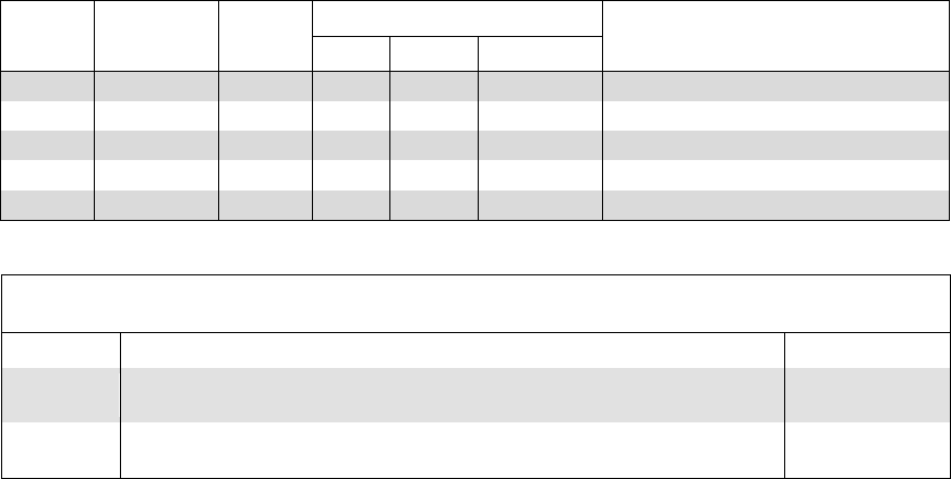
PRICE SCHEDULE A 2.0 January 2019
Advanced Replacement & Repair
Page 18 Prices and specifications subject to change without notice.
Loop Detectors
Circuit
Board
Model(s)
Used On REV
Options Available
Notes
Repair Advance Replace
9409-010 Loop Detector A - G No No Replace detector.
9409-010 Loop Detector H - Higher Yes Yes
9410-010 Loop Detector A - G No No Replace detector.
9410-010 Loop Detector H - Higher Yes Yes
9411-010 Loop Detector All Yes Yes
Loop Detector Boards
Code
Description
List
Repair E
XCHG E
9409-010 Repair and return.
9409-010 Advance replacement.
80.00
100.00
Repair E
XCHG E
9410-010 Repair and return.
9410-010 Advance replacement.
80.00
100.00
Page Rev 1/2/19

January 2019 PRICE SCHEDULE B 1.5
Maximum Security Slide Gate Operators
Specifications subject to change without notice. Page 1
Section B1
This Price Schedule is effective January 7, 2019.
Maximum Security Slide Gate Operators
Date Page Comment
1-2-19
All
January, 2019 Price Schedule update.

PRICE SCHEDULE B 1.5
Maximum Security Slide Gate Operators January 2019
Page 2 Specifications subject to change without notice.
Maximum Security Operators
9200 and 9500 series operators are designed to operate vehicular sliding gates used in Limited (Class III) and Restricted
(Class IV) industrial and maximum security applications only. These operators must never be used in Residential (Class I) or
Commercial (Class II) applications, or in any application where the gate is operated by the General Public.
These operators must be installed with external entrapment prevention devices, Type B1 (non-contact) or Type B2
(contact), or a combination of both to insure all entrapment hazard areas are protected. Refer to the Installation Manual
for important safety information.
Minimum Gate Length
Most 9200 and 9500 Series operators have variable speed capability which allows the user to adjust the speed of the gate.
On most operators, the speed can be set for speeds up to 2 Ft/sec., and on certain models the gate speed can be set up to
4 Ft/sec. When using these higher speeds, there is a time factor to consider during the start-up and the slow-down of the
gate. For this reason, you will see a minimum gate length on operators design to move a gate at the higher speeds.

January 2019 PRICE SCHEDULE B 1.5
Maximum Security Slide Gate Operators
Specifications subject to change without notice. Page 3
UL 325 – August 2018 Update
Requirements mandated by the safety standard (UL 325) that DKS gate operators are listed to require that photo-beams
and contact edges used for entrapment protection must be monitored. Entrapment protection must be provided for the
gate system where the risk of entrapment exist. The gate operator will not run without one or more external entrapment
protection devices installed in each direction of travel. Check the gate operator installation manual for a list of external
entrapment protection devices that can be used with DKS gate operator products.
The August, 2018 update to the safety standard requires that a minimum of two independent means of entrapment
protection must be provided, in each direction of travel, where the risk of entrapment exists. The inherent system in DKS
gate operators is active in both directions of travel, so this qualifies as one means of entrapment protection in each
direction. The second means will be an external device (a non-contact or a contact sensor) as required in each direction.
The actual number of external devices required is dependent on the gate system layout and the number of entrapment
areas that will need to be protected. Installers will have to identify all potential areas where the risk of entrapment exist
and how best to protect those areas. For example, some gates may require two (or more) external devices in each
direction of travel to protect all potential areas of entrapment.
There is an exception for swing gates and vertical lift gates regarding the minimum of two entrapment protection devices
in each direction of travel. For example, if on a swing gate system there is no potential for entrapment in the opening
direction, then only the close direction will require a minimum of two means of entrapment protection. Installers will have
to determine if any entrapment hazards exist in the opening direction, and if so, then those areas will have to be protected
with external devices.
Vertical lift gates require two means of entrapment protection in the down cycle, but will only require one means of
entrapment protection in the up cycle. The model 1175 is considered to be a vertical lift gate operator for entrapment
protection means requirements.
Barrier gate operators that are installed in such a way that the barrier arm does not come closer than 16 inches to a rigid
object are not required to protect against entrapment.
The table below shows the minimum entrapment protection requirements for each type of gate operator in the scope of
the UL 325 Standard for Safety.
Opening
Closing
Horizontal Slide Gate
2
2
Horizontal Swing Gate
2*
2*
Vertical Pivot Gate
2
2
Vertical Lift gate
1
2
* For a horizontal swing gate operator, at least two independent entrapment protection means are required in each
direction of travel. Except, if there is no entrapment zone in one direction of travel, only one means of entrapment
protection is required in that direction of travel; however, the other direction must have two independent entrapment
protection means.
Page Rev 1/2/19

PRICE SCHEDULE B 1.5
Maximum Security Slide Gate Operators January 2019
Page 4 Specifications subject to change without notice.
Blank Page
Page Rev 1/2/19

January 2019 PRICE SCHEDULE B 1.5
Maximum Security Slide Gate Operators
Specifications subject to change without notice. Page 5
Table of Contents
Maximum Security Slide Gate Operators
Model 9210 ............................................................................................................................................................................... 4
Model 9220 ............................................................................................................................................................................... 6
Model 9230 ............................................................................................................................................................................... 8
Model 9235 ............................................................................................................................................................................. 10
Model 9240 ............................................................................................................................................................................. 12
Heavy-Duty Maximum Security Slide Gate Operators
Model 9530 ............................................................................................................................................................................. 14
Model 9550 ............................................................................................................................................................................. 16
Model 9555 ............................................................................................................................................................................. 18
Model 9575 ............................................................................................................................................................................. 20
Page Rev 1/2/19
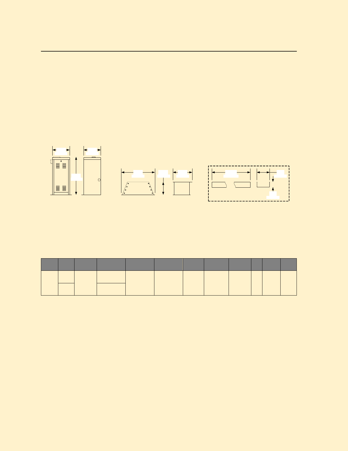
PRICE SCHEDULE B 1.5
Maximum Security Slide Gate Operators January 2019
Page 6 Specifications subject to change without notice.
9210 Slide Gate Operator
Maximum Security Slide Gate Operator
• 40:1 Gear Reducer Drive Train
• Fixed Speed
• 20-Feet (6m) #50 / #60 Chain
• Gate tracker data output
• Selectable stop/ reverse function
9210
• Adjustable Limits
• Plug-in Loop Detector Ports
• Built-in power and reset switches
• Two 115 VAC convenience outlets
• Partial open / anti-tailgate feature
120.00 4.00
1.75
35.50
16.00 16.00
31.25 18.0012.00
406 mm 406 mm
902 mm
9210 -xxx 9200-135
794 mm 305 mm 457 mm
44 mm
102 mm3048 mm
2601-270
Not to Scale
Model
Chain
Speed
Fixed
Maximum
Gate Weight
Maximum
Gate Length
Minimum
Gate Length
Mount
Class of
Operation1
Voltage
VAC
HP
Power
Outlets
Loop
Ports2
9210
#50
1 Ft/sec
.3m/sec
2000 Lbs3
907 Kg 100 Ft
30m
10 Ft
3m
Pad or
Pedestal3 III, IV 115, 208,
230, 460 1 2 2
#60 3000 Lbs3
1360 Kg
1. III = Limited Access; IV = Restricted Access
2. Plug-in loop detector ports; open and reverse. DoorKing plug-in loop detectors only.
3. Requires 9200-135 pedestal.
Page Rev 1/2/19

January 2019 PRICE SCHEDULE B 1.5
Maximum Security Slide Gate Operators
Specifications subject to change without notice. Page 7
9210 Slide Gate Operator
Maximum Security Slide Gate Operator
Accessories
9200-135 Mounting Pedestal ....................................... 894.00
2601-270 Chain Tray Kit 10 Ft (3m)1 ............................. 399.00
1601-195 Heater Kit 120 VAC2 ...................................... 759.00
1601-197 Heater Kit 208/230 VAC2 .............................. Note 3
1601-198 Heater Kit 480 VAC2 ...................................... Note 3
1. 9200-135 required if chain tray is used.
2. Use if temperature routinely falls below 10°F (-12°C).
3. See Section A1, page 31 for pricing.
Chain
2600-485 #50 Chain, 20-Ft (6 m) .................................. 165.00
2600-448 #60 Chain, 20-Ft (6 m) .................................. 264.00
Operators w/#50 Chain
9210-380 1 HP, 115V (9.7A) ....................................... 4890.00
9210-382 1 HP, 208V 1° (5.0A) ................................... 4942.50
9210-384 1 HP, 230V 1° (4.9A) ................................... 4942.50
9210-386 1 HP, 208V 3° (3.4A) ................................... 5160.00
9210-388 1 HP, 230V 3° (3.3A) ................................... 5160.00
9210-390 1 HP, 460V 3° (1.7A) ................................... 5160.00
Operators w/#60 Chain
9210-381 1 HP, 115V (9.7A) ....................................... 4965.00
9210-383 1 HP, 208V 1° (5.0A) ................................... 5025.00
9210-385 1 HP, 230V 1° (4.9A) ................................... 5025.00
9210-387 1 HP, 208V 3° (3.4A) ................................... 5242.50
9210-389 1 HP, 230V 3° (3.3A) ................................... 5242.50
9210-391 1 HP, 460V 3° (1.7A) ................................... 5242.50
Choose Entrapment Protection (required) Devices
Use Type B1 (non-contact) and/or Type B2 (contact) entrapment
protection devices to protect all areas where the risk of entrapment
exist - see Section A1, pages 42-43.
Operator will not run without entrapment protection device(s)
connected to the controller board.
Loops and Loop Detectors
See section A1, page 44 for a complete list of all loop detectors,
prefabricated loops and loop accessories available.
Page Rev 1/2/19
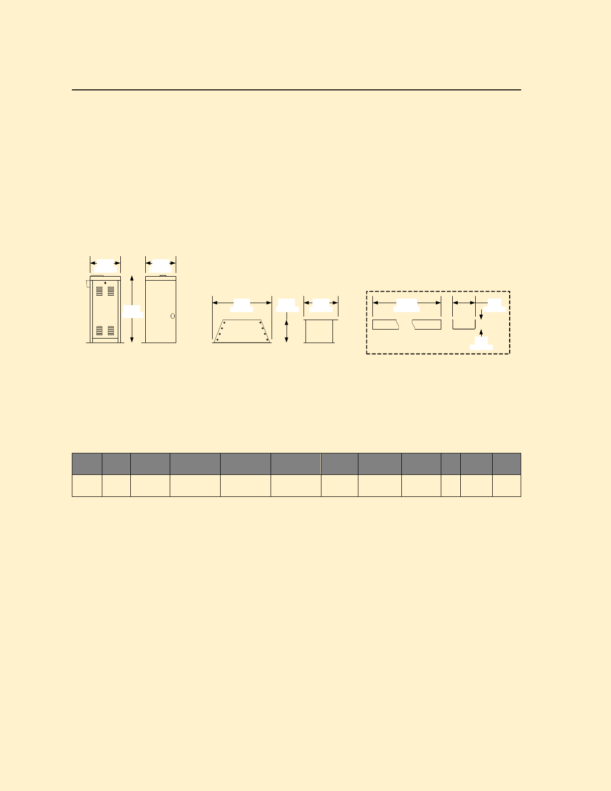
PRICE SCHEDULE B 1.5
Maximum Security Slide Gate Operators January 2019
Page 8 Specifications subject to change without notice.
9220 Slide Gate Operator
Maximum Security Slide Gate Operator
• 40:1 Gear Reducer Drive Train
• Variable Speed
• 20-Feet (6m) #60 Chain
• Gate tracker data output
• Selectable stop/ reverse function
9220
• Adjustable Limits
• Plug-in Loop Detector Ports
• Built-in power and reset switches
• Two 115 VAC convenience outlets
• Partial open / anti-tailgate feature
120.00 4.00
1.75
35.50
16.00 16.00
31.25 18.00
12.00
406 mm 406 mm
902 mm
9220 -xxx 9200-135
794 mm 305 mm 457 mm
44 mm
102 mm
3048 mm
2601-270
Not to Scale
Model
Chain
Speed
Variable
Maximum
Gate Weight
Maximum
Gate Length
Minimum
Gate Length
Mount
Class of
Operation1
Voltage
VAC
HP
Power
Outlets
Loop
Ports2
9220 #60 1-2 Ft/sec
.3-.6m/sec
2000 Lbs3
907 Kg
100 Ft
30m
20 Ft
6m
Pad or
Pedestal3 III, IV 208, 230,
460 2 2 2
1. III = Limited Access; IV = Restricted Access
2. Plug-in loop detector ports; open and reverse. DoorKing plug-in loop detectors only.
3. Requires 9200-135 pedestal.
Page Rev 1/2/19

January 2019 PRICE SCHEDULE B 1.5
Maximum Security Slide Gate Operators
Specifications subject to change without notice. Page 9
9220 Slide Gate Operator
Maximum Security Slide Gate Operator
Accessories
9200-135 Mounting Pedestal ....................................... 894.00
2601-270 Chain Tray Kit 10 Ft (3m)1 ............................. 399.00
1601-197 Heater Kit 208/230 VAC2 .............................. Note 3
1601-198 Heater Kit 480 VAC2 ...................................... Note 3
1. 9200-135 required if chain tray is used.
2. Use if temperature routinely falls below 10°F (-12°C).
3. See Section A1, page 31 for pricing.
Chain
2600-448 #60 Chain, 20-Ft (6 m) .................................. 264.00
Operators w/#60 Chain
9220-381 2 HP, 208V 1° (11.7A) ................................. 6052.50
9220-383 2 HP, 230V 1° (11.5A) ................................. 6052.50
9220-385 2 HP, 208V 3° (6.6A) ................................... 6270.00
9220-387 2 HP, 230V 3° (6.2A) ................................... 6270.00
9220-389 2 HP, 460V 3° (3.1A) ................................... 6270.00
Choose Entrapment Protection (required) Devices
Use Type B1 (non-contact) and/or Type B2 (contact) entrapment
protection devices to protect all areas where the risk of entrapment
exist - see Section A1, pages 42-43.
Operator will not run without entrapment protection device(s)
connected to the controller board.
Loops and Loop Detectors
See section A1, page 44 for a complete list of all loop detectors,
prefabricated loops and loop accessories available.
Page Rev 1/2/19
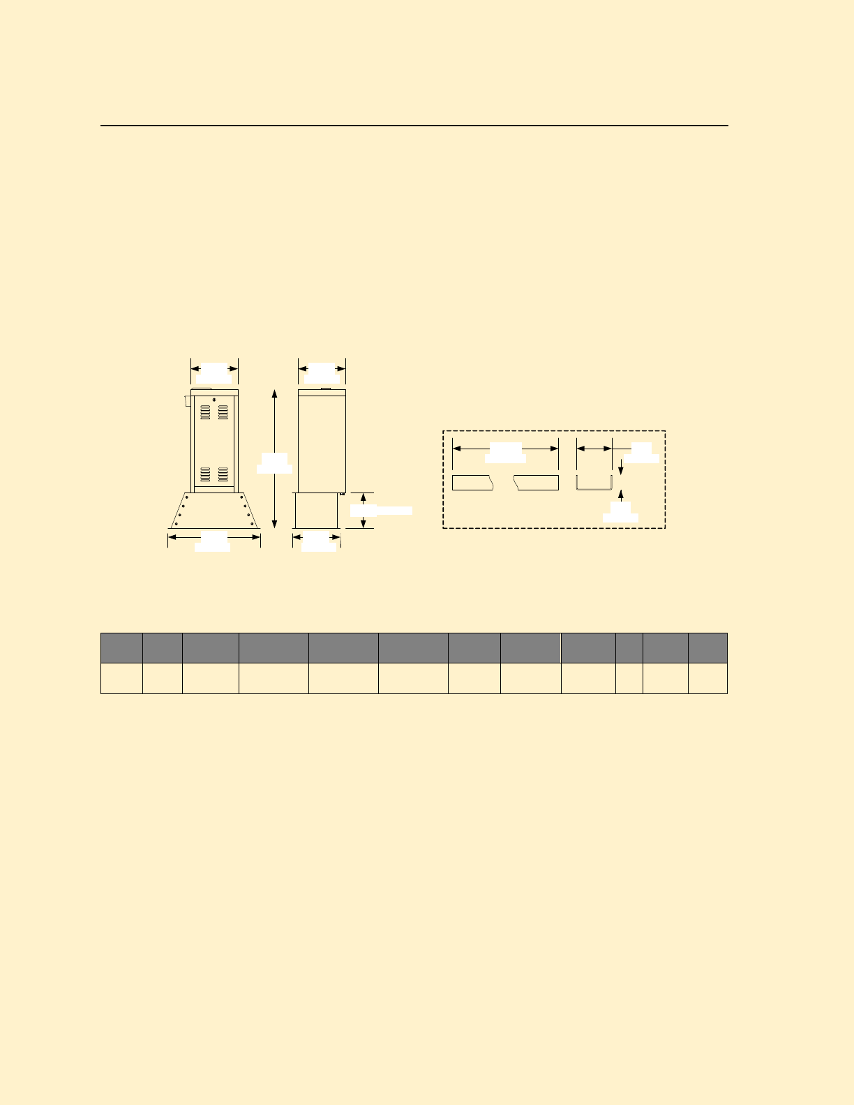
PRICE SCHEDULE B 1.5
Maximum Security Slide Gate Operators January 2019
Page 10 Specifications subject to change without notice.
9230 Slide Gate Operator
Maximum Security Slide Gate Operator
• 40:1 Gear Reducer Drive Train
• Variable Speed
• 20-Feet (6m) #60 Chain
• Gate tracker data output
• Selectable stop/ reverse function
9230
• Adjustable Limits
• Plug-in Loop Detector Ports
• Built-in power and reset switches
• Two 115 VAC convenience outlets
• Partial open / anti-tailgate feature
47.00
16.00
31.25 16.25
12.00
16.00
406 mm
120.00 4.00
1.75
44 mm
102 mm3048 mm
2601-270
Not to Scale
406 mm
1206 mm
794 mm 413 mm
305 mm
9230-xxx
Model
Chain
Speed
Variable
Maximum
Gate Weight
Maximum
Gate Length
Minimum
Gate Length
Mount
Class of
Operation1
Voltage
VAC
HP
Power
Outlets
Loop
Ports2
9230 #60 1-2 Ft/sec
.3-.6m/sec
5000 Lbs3
2267 Kg
100 Ft
30m
20 Ft
6m Pedestal3 III, IV 208, 230 3 2 2
1. III = Limited Access; IV = Restricted Access
2. Plug-in loop detector ports; open and reverse. DoorKing plug-in loop detectors only.
3. 9200-135 pedestal included.
Page Rev 1/2/19

January 2019 PRICE SCHEDULE B 1.5
Maximum Security Slide Gate Operators
Specifications subject to change without notice. Page 11
9230 Slide Gate Operator
Maximum Security Slide Gate Operator
Accessories
2601-270 Chain Tray Kit 10 Ft (3m) .............................. 399.00
1601-197 Heater Kit 208/230 VAC1 .............................. Note 2
1. Use if temperature routinely falls below 10°F (-12°C).
2. See Section A1, page 31 for pricing.
Chain
2600-448 #60 Chain, 20-Ft (6 m) .................................. 264.00
Operators w/#60 Chain
9230-380 3 HP, 208V 3° (9.8A) ................................... 8730.00
9230-381 3 HP, 230V 3° (9.6A) ................................... 8730.00
Choose Entrapment Protection (required) Devices
Use Type B1 (non-contact) and/or Type B2 (contact) entrapment
protection devices to protect all areas where the risk of entrapment
exist - see Section A1, pages 42-43.
Operator will not run without entrapment protection device(s)
connected to the controller board.
Loops and Loop Detectors
See section A1, page 44 for a complete list of all loop detectors,
prefabricated loops and loop accessories available.
Page Rev 1/2/19

PRICE SCHEDULE B 1.5
Maximum Security Slide Gate Operators January 2019
Page 12 Specifications subject to change without notice.
9235 Slide Gate Operator
Maximum Security Slide Gate Operator
• 40:1 Gear Reducer Drive Train
• Variable Speed
• 20-Feet (6m) #60 Chain
• Gate tracker data output
• Selectable stop/ reverse function
9235
• Adjustable Limits
• Plug-in Loop Detector Ports
• Built-in power and reset switches
• Two 115 VAC convenience outlets
• Partial open / anti-tailgate feature
47.00
16.00
31.25 16.25
12.00
16.00
406 mm
120.00 4.00
1.75
44 mm
102 mm3048 mm
2601-270
Not to Scale
406 mm
1206 mm
794 mm 413 mm
305 mm
9235-xxx
Model
Chain
Speed
Variable
Maximum
Gate Weight
Maximum
Gate Length
Minimum
Gate Length
Mount
Class of
Operation1
Voltage
VAC
HP
Power
Outlets
Loop
Ports2
9235 #60 1-4 Ft/sec
.3-1.2m/sec
3000 Lbs3
1360 Kg
100 Ft
30m
30 Ft
9m Pedestal3 III, IV 208, 230 3 2 2
1. III = Limited Access; IV = Restricted Access
2. Plug-in loop detector ports; open and reverse. DoorKing plug-in loop detectors only.
3. 9200-135 pedestal included.
Page Rev 1/2/19

January 2019 PRICE SCHEDULE B 1.5
Maximum Security Slide Gate Operators
Specifications subject to change without notice. Page 13
9235 Slide Gate Operator
Maximum Security Slide Gate Operator
Accessories
2601-270 Chain Tray Kit 10 Ft (3m) .............................. 399.00
1601-197 Heater Kit 208/230 VAC1 .............................. Note 2
1. Use if temperature routinely falls below 10°F (-12°C).
2. See Section A1, page 31 for pricing.
Chain
2600-448 #60 Chain, 20-Ft (6 m) .................................. 264.00
Operators w/#60 Chain
9235-380 3 HP, 208V 3° (12.8A) .............................. 13,005.00
9235-381 3 HP, 230V 3° (12.6A) .............................. 13,005.00
Choose Entrapment Protection (required) Devices
Use Type B1 (non-contact) and/or Type B2 (contact) entrapment
protection devices to protect all areas where the risk of entrapment
exist - see Section A1, pages 42-43.
Operator will not run without entrapment protection device(s)
connected to the controller board.
Loops and Loop Detectors
See section A1, page 44 for a complete list of all loop detectors,
prefabricated loops and loop accessories available.
Page Rev 1/2/19
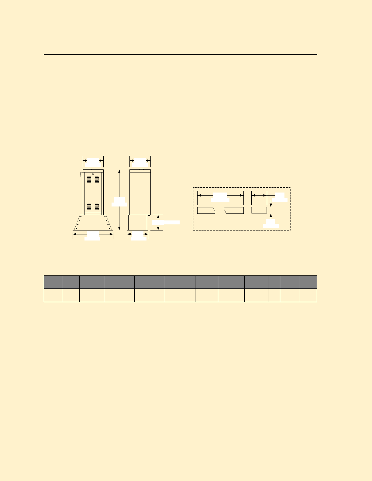
PRICE SCHEDULE B 1.5
Maximum Security Slide Gate Operators January 2019
Page 14 Specifications subject to change without notice.
9240 Slide Gate Operator
Maximum Security Slide Gate Operator
• 40:1 Gear Reducer Drive Train
• Variable Speed
• 20-Feet (6m) #80 Chain
• Gate tracker data output
• Selectable stop/ reverse function
9240
• Adjustable Limits
• Plug-in Loop Detector Ports
• Built-in power and reset switches
• Two 115 VAC convenience outlets
• Partial open / anti-tailgate feature
47.00
16.00
31.25 16.25
12.00
16.00
406 mm
120.00 4.00
1.75
44 mm
102 mm
3048 mm
2601-270
Not to Scale
406 mm
1206 mm
794 mm 413 mm
305 mm
9240-xxx
Model
Chain
Speed
Variable
Maximum
Gate Weight
Maximum
Gate Length
Minimum
Gate Length
Mount
Class of
Operation1
Voltage
VAC
HP
Power
Outlets
Loop
Ports2
9240 #80 1-2 Ft/sec
.3-.6m/sec
8000 Lbs3
3628 Kg
100 Ft
30m
25 Ft
7.6m Pedestal3 III, IV 208, 230 3 2 2
1. III = Limited Access; IV = Restricted Access
2. Plug-in loop detector ports; open and reverse. DoorKing plug-in loop detectors only.
3. 9200-135 pedestal included.
Page Rev 1/2/19

January 2019 PRICE SCHEDULE B 1.5
Maximum Security Slide Gate Operators
Specifications subject to change without notice. Page 15
9240 Slide Gate Operator
Maximum Security Slide Gate Operator
Accessories
2601-270 Chain Tray Kit 10 Ft (3m) .............................. 399.00
1601-197 Heater Kit 208/230 VAC1 .............................. Note 2
1. Use if temperature routinely falls below 10°F (-12°C).
2. See Section A1, page 31 for pricing.
Chain
2601-268 #80 Chain, 10-Ft (3 m) .................................. 249.00
2601-269 #80 Chain, 20-Ft (6 m) .................................. 501.00
Operators w/#80 Chain
9240-380 3 HP, 208V 3° (9.8A) ................................ 13,005.00
9240-381 3 HP, 230V 3° (9.6A) ................................ 13,005.00
Choose Entrapment Protection (required) Devices
Use Type B1 (non-contact) and/or Type B2 (contact) entrapment
protection devices to protect all areas where the risk of entrapment
exist - see Section A1, pages 42-43.
Operator will not run without entrapment protection device(s)
connected to the controller board.
Loops and Loop Detectors
See section A1, page 44 for a complete list of all loop detectors,
prefabricated loops and loop accessories available.
Page Rev 1/2/19

PRICE SCHEDULE B 1.5
Maximum Security Slide Gate Operators January 2019
Page 16 Specifications subject to change without notice.
9530 Slide Gate Operator
Heavy-Duty Maximum Security Slide Gate Operator
• 40:1 Gear Reducer Drive Train
• Variable Speed
• 20-Feet (6m) #80 Chain
• Gate tracker data output
• Selectable stop/ reverse function
9530
• Adjustable Limits
• Plug-in Loop Detector Ports
• Built-in power and reset switches
• Two 115 VAC convenience outlets
• Partial open / anti-tailgate feature
54.00 26.00
59.00
49.00 22.50
62.00
1372 mm 660 mm
1499 mm 1575 mm
572 mm
1245 mm
95xx-xxx with Standard Polyurethane housing 95xx-xxx with optional 10ga. Steel housing
Model
Chain
Speed
Variable
Maximum
Gate Weight
Maximum
Gate Length
Minimum
Gate Length
Mount
Class of
Operation1
Voltage
VAC
HP
Power
Outlets
Loop
Ports2
9530 #80 1-2 Ft/sec
.3-.6m/sec
8000 Lbs3
3628 Kg
160 Ft
48m
25 Ft
7.6m Pad III, IV 208, 230,
460 3 2 2
1. III = Limited Access; IV = Restricted Access
2. Plug-in loop detector ports; open and reverse. DoorKing plug-in loop detectors only.
Page Rev 1/2/19

January 2019 PRICE SCHEDULE B 1.5
Maximum Security Slide Gate Operators
Specifications subject to change without notice. Page 17
9530 Slide Gate Operator
Heavy-Duty Maximum Security Slide Gate Operator
Accessories
2601-270 Chain Tray Kit 10 Ft (3m) .............................. 399.00
1601-197 Heater Kit 208/230 VAC1 .............................. Note 2
1601-198 Heater Kit 480 VAC1 ...................................... Note 2
9550-205 10 Ga. Steel Housing3 ................................. 4095.00
1. Use if temperature routinely falls below 10°F (-12°C).
2. See Section A1, page 31 for pricing.
3. Special order. Contact the factory for lead time.
Chain
2601-268 #80 Chain, 10-Ft (3 m) .................................. 249.00
2601-269 #80 Chain, 20-Ft (6 m) .................................. 501.00
Operators w/#80 Chain
9530-380 3 HP, 208V 3° (9.8A) ................................ 14,595.00
9530-381 3 HP, 230V 3° (9.6A) ................................ 14,595.00
9530-382 3 HP, 460V 3° (4.8A) ................................ 14,595.00
Choose Entrapment Protection (required) Devices
Use Type B1 (non-contact) and/or Type B2 (contact) entrapment
protection devices to protect all areas where the risk of entrapment
exist - see Section A1, pages 42-43.
Operator will not run without entrapment protection device(s)
connected to the controller board.
Loops and Loop Detectors
See section A1, page 44 for a complete list of all loop detectors,
prefabricated loops and loop accessories available.
Page Rev 1/2/19

PRICE SCHEDULE B 1.5
Maximum Security Slide Gate Operators January 2019
Page 18 Specifications subject to change without notice.
9550 Slide Gate Operator
Heavy-Duty Maximum Security Slide Gate Operator
• 40:1 Gear Reducer Drive Train
• Variable Speed
• 20-Feet (6m) #100 Chain
• Gate tracker data output
• Selectable stop/ reverse function
9550
• Adjustable Limits
• Plug-in Loop Detector Ports
• Built-in power and reset switches
• Two 115 VAC convenience outlets
• Partial open / anti-tailgate feature
54.00 26.00
59.00
49.00 22.50
62.00
1372 mm 660 mm
1499 mm 1575 mm
572 mm
1245 mm
95xx-xxx with Standard Polyurethane housing 95xx-xxx with optional 10ga. Steel housing
Model
Chain
Speed
Variable
Maximum
Gate Weight
Maximum
Gate Length
Minimum
Gate Length
Mount
Class of
Operation1
Voltage
VAC
HP
Power
Outlets
Loop
Ports2
9550 #100 .5-1 Ft/sec
.15-.3m/sec
15,000 Lbs3
6803 Kg
160 Ft
48m
25 Ft
7.6m Pad III, IV 208, 230,
460 5 2 2
1. III = Limited Access; IV = Restricted Access
2. Plug-in loop detector ports; open and reverse. DoorKing plug-in loop detectors only.
Page Rev 1/2/19

January 2019 PRICE SCHEDULE B 1.5
Maximum Security Slide Gate Operators
Specifications subject to change without notice. Page 19
9550 Slide Gate Operator
Heavy-Duty Maximum Security Slide Gate Operator
Accessories
2601-270 Chain Tray Kit 10 Ft (3m) .............................. 399.00
1601-197 Heater Kit 208/230 VAC1 .............................. Note 2
1601-198 Heater Kit 480 VAC1 ...................................... Note 2
9550-205 10 Ga. Steel Housing3 ................................. 4095.00
1. Use if temperature routinely falls below 10°F (-12°C).
2. See Section A1, page 31 for pricing.
3. Special order. Contact the factory for lead time.
Chain
2601-272 #100 Chain, 20-Ft (6 m) ................................ 543.00
Operators w/#100 Chain
9550-380 5 HP, 208V 3° (12.9A) .............................. 25,215.00
9550-381 5 HP, 230V 3° (12.8A) .............................. 25,215.00
9550-382 5 HP, 460V 3° (6.4A) ................................ 25,215.00
Choose Entrapment Protection (required) Devices
Use Type B1 (non-contact) and/or Type B2 (contact) entrapment
protection devices to protect all areas where the risk of entrapment
exist - see Section A1, pages 42-43.
Operator will not run without entrapment protection device(s)
connected to the controller board.
Loops and Loop Detectors
See section A1, page 44 for a complete list of all loop detectors,
prefabricated loops and loop accessories available.
Page Rev 1/2/19
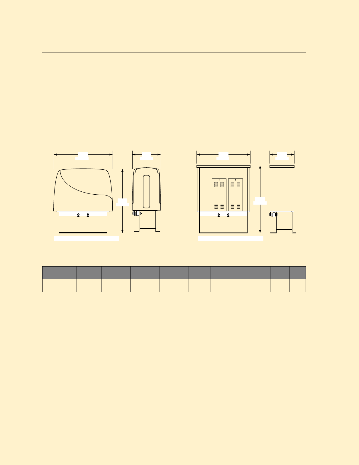
PRICE SCHEDULE B 1.5
Maximum Security Slide Gate Operators January 2019
Page 20 Specifications subject to change without notice.
9555 Slide Gate Operator
Heavy-Duty Maximum Security Slide Gate Operator
• 40:1 Gear Reducer Drive Train
• Variable Speed
• 20-Feet (6m) #80 Chain
• Gate tracker data output
• Selectable stop/ reverse function
9555
• Adjustable Limits
• Plug-in Loop Detector Ports
• Built-in power and reset switches
• Two 115 VAC convenience outlets
• Partial open / anti-tailgate feature
54.00 26.00
59.00
49.00 22.50
62.00
1372 mm 660 mm
1499 mm 1575 mm
572 mm
1245 mm
95xx-xxx with Standard Polyurethane housing 95xx-xxx with optional 10ga. Steel housing
Model
Chain
Speed
Variable
Maximum
Gate Weight
Maximum
Gate Length
Minimum
Gate Length
Mount
Class of
Operation1
Voltage
VAC
HP
Power
Outlets
Loop
Ports2
9555 #80 1-2 Ft/sec
.3-.6m/sec
10,000 Lbs3
4535 Kg
160 Ft
48m
25 Ft
7.6m Pad III, IV 208, 460 5 2 2
1. III = Limited Access; IV = Restricted Access
2. Plug-in loop detector ports; open and reverse. DoorKing plug-in loop detectors only.
Page Rev 1/2/19

January 2019 PRICE SCHEDULE B 1.5
Maximum Security Slide Gate Operators
Specifications subject to change without notice. Page 21
9555 Slide Gate Operator
Heavy-Duty Maximum Security Slide Gate Operator
Accessories
2601-270 Chain Tray Kit 10 Ft (3m) .............................. 399.00
1601-197 Heater Kit 208/230 VAC1 .............................. Note 2
1601-198 Heater Kit 480 VAC1 ...................................... Note 2
9550-205 10 Ga. Steel Housing3 ................................. 4095.00
1. Use if temperature routinely falls below 10°F (-12°C).
2. See Section A1, page 31 for pricing.
3. Special order. Contact the factory for lead time.
Chain
2601-268 #80 Chain, 10-Ft (3 m) .................................. 249.00
2601-269 #80 Chain, 20-Ft (6 m) .................................. 501.00
Operators w/#80 Chain
9555-380 5 HP, 208V 3° (12.9A) .............................. 20,835.00
9555-382 5 HP, 460V 3° (6.4A) ................................ 20,835.00
These operators include a mechanical disc braking system. A
brake auto-release can be factory ordered with this operator.
Choose Entrapment Protection (required) Devices
Use Type B1 (non-contact) and/or Type B2 (contact) entrapment
protection devices to protect all areas where the risk of entrapment
exist - see Section A1, pages 42-43.
Operator will not run without entrapment protection device(s)
connected to the controller board.
Loops and Loop Detectors
See section A1, page 44 for a complete list of all loop detectors,
prefabricated loops and loop accessories available.
Page Rev 1/2/19

PRICE SCHEDULE B 1.5
Maximum Security Slide Gate Operators January 2019
Page 22 Specifications subject to change without notice.
9575 Slide Gate Operator
Heavy-Duty Maximum Security Slide Gate Operator
• 40:1 Gear Reducer Drive Train
• Variable Speed
• 20-Feet (6m) #100 Chain
• Gate tracker data output
• Selectable stop/ reverse function
9575
• Adjustable Limits
• Plug-in Loop Detector Ports
• Built-in power and reset switches
• Two 115 VAC convenience outlets
• Partial open / anti-tailgate feature
54.00 26.00
59.00
49.00 22.50
62.00
1372 mm 660 mm
1499 mm 1575 mm
572 mm
1245 mm
95xx-xxx with Standard Polyurethane housing 95xx-xxx with optional 10ga. Steel housing
Model
Chain
Speed
Variable
Maximum
Gate Weight
Maximum
Gate Length
Minimum
Gate Length
Mount
Class of
Operation1
Voltage
VAC
HP
Power
Outlets
Loop
Ports2
9575 #100 1-2 Ft/sec
.3-.6m/sec
25,000 Lbs3
11,339 Kg
160 Ft
48m
25 Ft
7.6m Pad III, IV 208 7.5 2 2
1. III = Limited Access; IV = Restricted Access
2. Plug-in loop detector ports; open and reverse. DoorKing plug-in loop detectors only.
Page Rev 1/2/19

January 2019 PRICE SCHEDULE B 1.5
Maximum Security Slide Gate Operators
Specifications subject to change without notice. Page 23
9575 Slide Gate Operator
Heavy-Duty Maximum Security Slide Gate Operator
Accessories
2601-270 Chain Tray Kit 10 Ft (3m) .............................. 399.00
1601-197 Heater Kit 208/230 VAC1 .............................. Note 2
9550-205 10 Ga. Steel Housing3 ................................. 4095.00
1. Use if temperature routinely falls below 10°F (-12°C).
2. See Section A1, page 31 for pricing.
3. Special order. Contact the factory for lead time.
Chain
2601-272 #100 Chain, 20-Ft (6 m) ................................ 543.00
Operators w/#100 Chain
9575-380 7.5 HP, 208V 3° (22.6A) ........................... 32,850.00
Choose Entrapment Protection (required) Devices
Use Type B1 (non-contact) and/or Type B2 (contact) entrapment
protection devices to protect all areas where the risk of entrapment
exist - see Section A1, pages 42-43.
Operator will not run without entrapment protection device(s)
connected to the controller board.
Loops and Loop Detectors
See section A1, page 44 for a complete list of all loop detectors,
prefabricated loops and loop accessories available.
Page Rev 1/2/19

PRICE SCHEDULE B 1.5
Maximum Security Slide Gate Operators January 2019
Page 24 Specifications subject to change without notice.
Blank Page

PRICE SCHEDULE C 1.0
DKS Connection Option Fee Schedule Rev 1-19
DKS® (DoorKing®) Connection Options Fee Schedule
Programming your DKS telephone entry / access control system using legacy modem-to-modem connections (a modem and phone line at
your PC) is becoming difficult to maintain. Modems are essentially obsolete and their performance is affected by the type of telephone
service at your PC. There are also many variable factors that can affect the modem, including the brand and model of the programming PC,
which OS version is in use, is the modem connected directly to the PC or through a USB Hub, brand and chipset versions of the modem and
modem driver updates. Existing modem-to-modem connections may become unreliable as telephone providers update their systems and
infrastructure and as your PC performs updates. These factors are beyond the control of DoorKing.
Beginning January 1, 2017 DoorKing will no longer offer technical support for communication failures between a PC modem and the DKS
entry system modem. If the modem connection is found to be functional at the DKS entry system and DoorKing tech support personnel
can connect to it via the DKS IM Server connection service, then this will be the recommended corrective action. Alternately,
troubleshooting the PC modem will be the responsibility of the owner and their IT (Information Technology) personnel.
Because of these reasons, DoorKing offers a variety of connection options for our telephone entry and access control systems. These
options offer a simple plug & play method to program your entry system via an internet or cellular connection and we also offer options for
voice communications as well. The type of service you choose should be based on your particular needs, the application that the system is
installed in and overall costs associated with these options. In many cases, you will find that the DoorKing options are less costly than
legacy options such as a POTS (Plain Old Telephone Service) business line, VoIP (Voice over Internet Protocol) service providers or the time
and cost of IT (Information Technology) personnel setting up routers, firewalls, port forwarding, DDNS (Dynamic Domain Name System)
charges or static IP addresses.
DKS Cellular OptionTM
DKS Cellular is a wireless option that replaces standard telephone lines and internet connections and offers voice communication and/or
data (programming) to the DKS telephone entry / access control system via the AT&T 4G LTE cellular network (where available). DKS
Cellular is available in all states including Alaska and Hawaii and is also available in Puerto Rico, all U.S. territories, Canada and Mexico. This
is a monthly cellular subscription service without any long term contracts. DKS Cellular plans include all taxes, fees and charges for voice
and data communication, including long distance charges.
• Plug & Play installation. Requires DKS cellular adapter: 1800-080 for 1830 series; 1800-081 for Access Plus series; 1801-080 for
1800 series.
• Monthly fees range from $39.95 to $75.95 depending on minutes and/or data used, so your monthly fees may vary from month
to month. In many cases, DKS cellular fees will be less than POTS (Plain Old Telephone Service) line charges.
• No phone lines or internet connection cables to run – no trenching or conduits to install.
• No obsolete slow modems – entry systems program much faster.
• Cellular offers crystal clear sound – no hums or buzzes.
• Cellular is practically immune to power surges and lightning damage.
• Use Voice + Data with PC programmable 1830 Series and Access Plus systems. Use Voice only with 1800 Series systems. Use
Data only with 1838 Series access controllers.
DKS Cellular1
Voice + Data
Monthly Fee
Voice Only2
Monthly Fee
Data Only
Monthly Fee
Voice
Minutes/Month
Data
Transfers/Month
Voice
Minutes/Month
Data
Transfers/Month
Up to 100
Up to 6
39.95
Up to 100
34.95
Up to 60
28.95
101 - 450
7 - 60
49.95
101 - 450
41.95
61 - 120
38.95
451 - 1200
61 - 90
59.95
451 - 1200
49.95
121 +
48.95
1201 - 2500
91 - 120
69.95
1201 - 2500
57.95
2500 +
121 +
75.95
2500 +
64.95
1. DKS Cellular is provided by AT&T 4G-LTE (where available). $45.00 one-time activation fee applies.
2. Voice only cellular option will not support modem communication.

PRICE SCHEDULE C 1.0
DKS Connection Option Fee Schedule Rev 1-19
DKS VoIP and Data Options
DKS VoIP and Data services allow you to replace POTS (Plain Old Telephone Service) lines with your internet connection and offers voice
communication and/or data (programming) to the DKS telephone entry / access control system. This is a flat rate monthly subscription
service without any long term contracts and includes all taxes, fees and charges for voice and/or data communication.
• Plug & Play installation. Requires DKS 1830-186 TCP/IP adapter for programming. DKS 1815-568 VoIP adapter required for voice
service. As an option, use the DKS 1830-185 TCP/IP1 adapter and your own VoIP3 provider.
• Data + VoIP combination simplifies installation. Requires DKS 2334-080 with VoIP + Data subscription.
• Flat rate monthly fee: voice and data $23.952, voice only $19.952; data only $4.95.
• Requires a network (internet) connection at the system – distance limitations on network wiring do apply.
• You can use your own VoIP service3 and the DKS Data only option for programming.
1. There is a no fee option that will allow you to connect to the entry system via the internet without using DKS data services. This adapter requires manual configuration and fees
or charges may be incurred for a static IP address or DDNS (Dynamic Domain Name System) host service. You will also need to use your own VoIP service for communication.
2. VoIP service provided by DKS.
3. If you use your own VoIP service, you will responsible for all charges for this service including hardware, subscription, taxes and other fees.
DKS VoIP and Data Options
VoIP + Data
Monthly Fee4
VoIP Only
Monthly Fee4
Data Only
Monthly Fee
Flat Rate
23.95
Flat Rate
19.95
Flat Rate
4.95
4. Includes VoIP service provided by DKS.
DKS IM Server ModemTM (Pat: 9,049,306)
DKS IM Server utilizes the POTS (Plain Old Telephone Service) line connected to the telephone entry system to provide data (programming)
transfer to the DKS telephone entry / access control system via the internet connection at your programming computer. Voice
communication is provided over the POTS line. This service is useful if your programming PC does not have a modem, or if your modem
cannot communicate with the entry system modem1. This is a monthly subscription service without any long term contracts and includes
taxes and charges for the data communication only. DKS IM Server Modem is only available for use with 1830 series and Access Plus series
systems.
• Plug & Play Data transfer connection – voice service provided by local telephone company.
• Monthly fees range from $6.95 to $15.45 depending on the number of residents in the system database.
• DoorKing maintains the right to determine excessive usage (data transfers) at any time and may require you to reduce your
usage (data transfers). Failure to comply may result in service termination.
• Requires a POTS (Plain Old Telephone Service) line1 at the entry system. User is responsible for all phone company charges
including local and long distance charges, taxes and other fees for this line.
1. DoorKing can no longer guarantee modem connections as some phone company services and switches no longer support modem communications since these devices are
considered to be obsolete technology. The telephone line at the entry system must support G.711 level service for the IM Server Modem to work. You should also be aware
that modem communications will not work over cellular or VoIP connections.
DKS IM Server ModemPat: 9,049,306 (Existing Phone Line Service2)
Voice + Data
Pay per Month
Pay per Year
Up to 100 Residents
6.95
76.45
101 – 250 Residents
9.45
103.95
251 – 500 Residents
11.95
131.45
501 + Residents
15.45
169.95
2. POTS (Plain Old Telephone Service) line at the entry system provided by the local telephone company. User is responsible for all phone company charges including local and long
distance charges, taxes and other fees for this line.
