DoorKing Door King 2358 Series Owner's Manual 065 T 5 18 Tracker Expansion
User Manual: DoorKing DoorKing 2358 Series Owner's Manual Owner's Manual
Open the PDF directly: View PDF ![]() .
.
Page Count: 40

Use this manual for circuit board 2358-010 Revision M or higher.
HARDwired Installation/
Owner’s Manual
Tracker Expansion Board
Tracker Expansion Board
Tracker Expansion Board
Tracker Expansion Board
Copyright 2018 DoorKing, Inc. All rights reserved.
Date Installed:
Installer/Company Name:
Phone Number:
Leave Manual with Owner
Circuit Board
Serial Number(s)
and Revision Letter:
Provides Access Control System expansion to
manage Up to 48 additional Access Points.
For Models:
1833, 1835, 1837 and 1838 Multi-Door Access Controller
Quad Board
Enclosure
(Not Included)
Single Board
Enclosure
(Not Included)
Wiegand Compatable
Single Board
Enclosure
with Built-In
Card Reader
(Not Included)
This access control equipment must be installed inside of a controlled, protected or restricted area to comply with UL 294 certification.
34
33
32
31
30
29
28
27
26
25
24
23
22
21
14
15
16
17
18
19
20
13
12
11
10
9
8
7
6
5
4
3
2
1
ON
1
0
BOARD ADDRESS
0
9
8
7
6
5
4
3
2
1
NC
OUTPUT
RELAY
NO
NC
ALARM
RELAY
NO
NC
AUX
RELAY
NO
ENT
RESET
2358-010
RF
DATA
RF
SECURE
RF
STATUS
CODE
SENT
CODE
GOOD
CODE
BAD
2358-010 sn XXXX
Rev M
Conforms To UL STD 294
2358-065-T-5-18

2358-065-T-5-18 1
SECTION 1 - TRACKER EXPANSION BOARD INTRODUCTION 2
1.1 General Information
1.2 General System Layout
1.3 Tracker Expansion Boards Layout Options
1.4 Tracker Expansion Board Overview
1.5 Board Input Descriptions
1.6 Setting Board Address (Software - System Relay)
1.7 Relay Identification (Software - System Relay)
1.8 13+ Jumper
2
3
3
4
5
6
7
8
SECTION 2 - INSTALLATION 9
9-11
12
12
13
2.1 System Layout Examples
2.2 Single Board Enclosure
2.3 Quad Board Enclosure
2.4 Single Board Enclosure with Card Reader
13
14
15
16
17
18
19
20
21
22-25
SECTION 3 - HARDWIRING 13
3.1 General HARDwiring Information
3.2 Board Addresses 3-10 Communication Line HARDwiring
3.3 Board Addresses 11-18 Communication Line HARDwiring
3.4 MAX Boards Communication Line HARDwiring
3.5 Basic Board Wiring Options at Access Point
3.6 Alarm Wiring Options at Access Point
3.7 All Available Devices at Access Point
3.8 Typical Dual Mode Wiring at 2 Access Points
3.9 Quad Box Wiring
3.10 Gate Operator Data Wiring - Optional Control Wiring
SECTION 4 - PROGRAMMING 26
4.1 LED and Button Descriptions
4.2 Programming
4.3 Programming Step Descriptions
26
26-28
29-31
SECTION 5 - TROUBLESHOOTING 32
5.1 Wiegand Device Data
5.2 Gate Operator Data
5.3 Gate Operator Event (transaction) Reports
5.4 Complete System Information
32
33
34
35-36
TABLE OF CONTENTS
DoorKing, Inc. reserves the right to make changes in the products described in this manual without notice and without obligation of DoorKing, Inc. to notify any persons
of any such revisions or changes. Additionally, DoorKing, Inc. makes no representations or warranties with respect to this manual. This manual is copyrighted, all rights
reserved. No portion of this manual may be copied, reproduced, translated, or reduced to any electronic medium without prior written consent from DoorKing, Inc.
ACCESS CONTROL SYSTEM: A collection of means, measures and specific practices that when combined, form or compose a systematic
approach, which enables an authority to control access to areas and resources in a given physical facility. An access control system, within
the field of physical security, is generally seen as the second layer in the security of a physical structure.
ALARM: A condition indicating a state of alert or tamper detection.
ALARM SIGNAL: A transmission of an alarm condition or alarm report.
CONTROLLED AREA: A room, office, building, facility, premises, or grounds to which access is monitored, limited, or controlled.
EQUIPMENT: Any part of an electronic access control system, such as access control units, reader interface modules, access point actuators,
access point sensors, keypads, and the like.
PROTECTED AREA: A room, office, building, facility, premise or grounds to which access is monitored, and limited and/or controlled,
whereby the authorized person of the Access Control System may grant access to non-authorized persons.
RESTRICTED AREA: A room, office, building, facility, premise or grounds to which access is monitored, and limited and strictly controlled,
whereby only the administrator of the Access Control System shall issue credentials that will lead to access.
Glossary
2358-065-T-5-18
2
SECTION 1 - TRACKER EXPANSION BOARD INTRODUCTION
The Model 2358 Tracker Expansion Board allows you to expand the number of access points that the models 1833, 1835, 1837 and 1838
multi-door access controller PC Programmable Entry Systems can control, up to a maximum of 48. One tracker expansion board is required
for each access point. Tracker expansion boards will interface with a variety of wiegand devices including card readers, RF transmitters,
digital keypads, etc. The tracker expansion board will also report gate operator data from DoorKing intelligent gate operators that have Gate
Tracker outputs. In addition to these features, the tracker expansion boards can also monitor the status of a door, report door ajar and forced
entry conditions, sound local alarms, activate a building alarm system, and has request to exit inputs.
Prior to beginning the installation, we suggest that you become familiar with the instructions, illustrations, and wiring guidelines in this
manual. This will help insure that your installation is performed in an efficient and professional manner.
The proper installation is an extremely important and integral part of the overall access control system. Check all local building ordinances and
building codes prior to installion. Be sure your installation is in compliance with local codes.
IMPORTANT Wireless installation of the access control system and tracker expansion boards will vary
from the HARDwire installation illustrated in this manual, see the instructions in the wireless kits for
wireless installation.
To utilize the tracker expansion board(s), DoorKing Remote Account Manager for Windows software, V 6.3i or newer is required to be
installed on the user supplied PC. The chart below is to assist you in determining if you have the proper access control system and gate
operators to utilize the tracker expansion board.
Model Control Board
Access Control Systems
1833, 1835, 1837, *1838183x-010 Series
1601, 1602, 1603 Barrier
Model
1601-010
Control Board
Gate Operators
1150 Overhead 4402-010
6524 Swing, 9024 Slide (AC Powered ONLY) 4100-010
9200, 9500 Slide 4404-010
6500 Swing, 9000 Slide 4405-010
6050, 6100, 6300 Swing 4502-010
9100, 9150 Slide 4602-010
1.1 General Information
• Expands the control capability of selected DoorKing access control systems to manage up to 48 additional access points.
• Provides power and wiegand inputs for almost any wiegand access control device (Card reader, RF receiver, digital keypad etc.). Board
may power two card readers in parallel if required. For example: an entry and exit card reader on a single door.
• Can be used to provide a variety of door monitoring functions, such as sounding an alarm, or activating a building alarm system when
the door is forced or held open.
• Provides a request to exit input (free exit).
• Provides three programmable relay outputs.
• Hold Open Feature unlocks individual doors (or holds open individual gates) when commanded from the system software.
• Monitors transactions from DoorKing intelligent gate operators. Can monitor slide, swing or overhead gate operators and the
parking gate operator (barrier) in PAMS type applications.
• Optional Wireless kit available to connect tracker expansion board(s) to an access control system wirelessly. Maximum distances
between the access control system and tracker expansion boards will vary from the HARD wire run distances illustrated in this manual,
see the instruction manuals with the wireless kits for the correct distances between the hardware.
* 1838 Multi-Door Access Controller ONLY. NOT for use with 1838 Access Plus.
Use this manual for Tracker Expansion Board 2358-010 Rev M or higher.
Destructive Attack: Level I
Line Security: Level I
Endurance: Level IV
Standby Power: Level I
This access control equipment must be installed inside of a controlled, protected or
restricted area to comply with UL 294 certification. See page 1 for more information.
2358-065-T-5-18 3
WARNING If the access control system is used to control a vehicular gate with an automatic gate operator, the access control device
must be mounted a minimum of six (6) feet away from the gate and gate operator, ten (10) feet recommended, or in such a way that a
person cannot operate the access control device and touch the gate or gate operator at the same time.
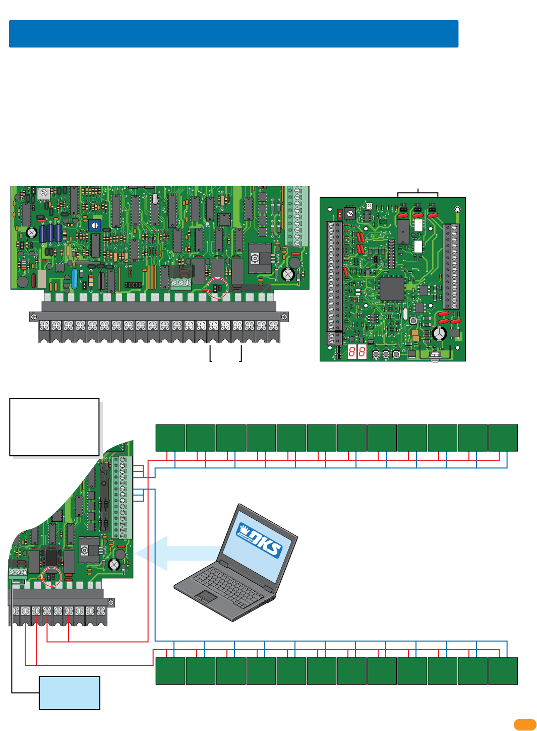
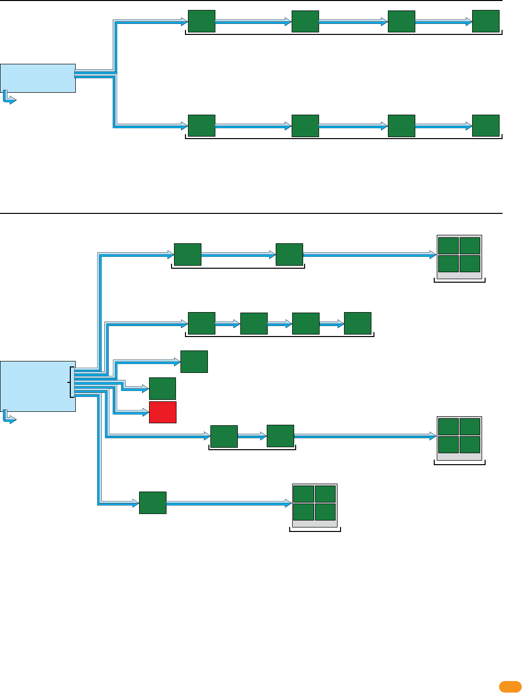
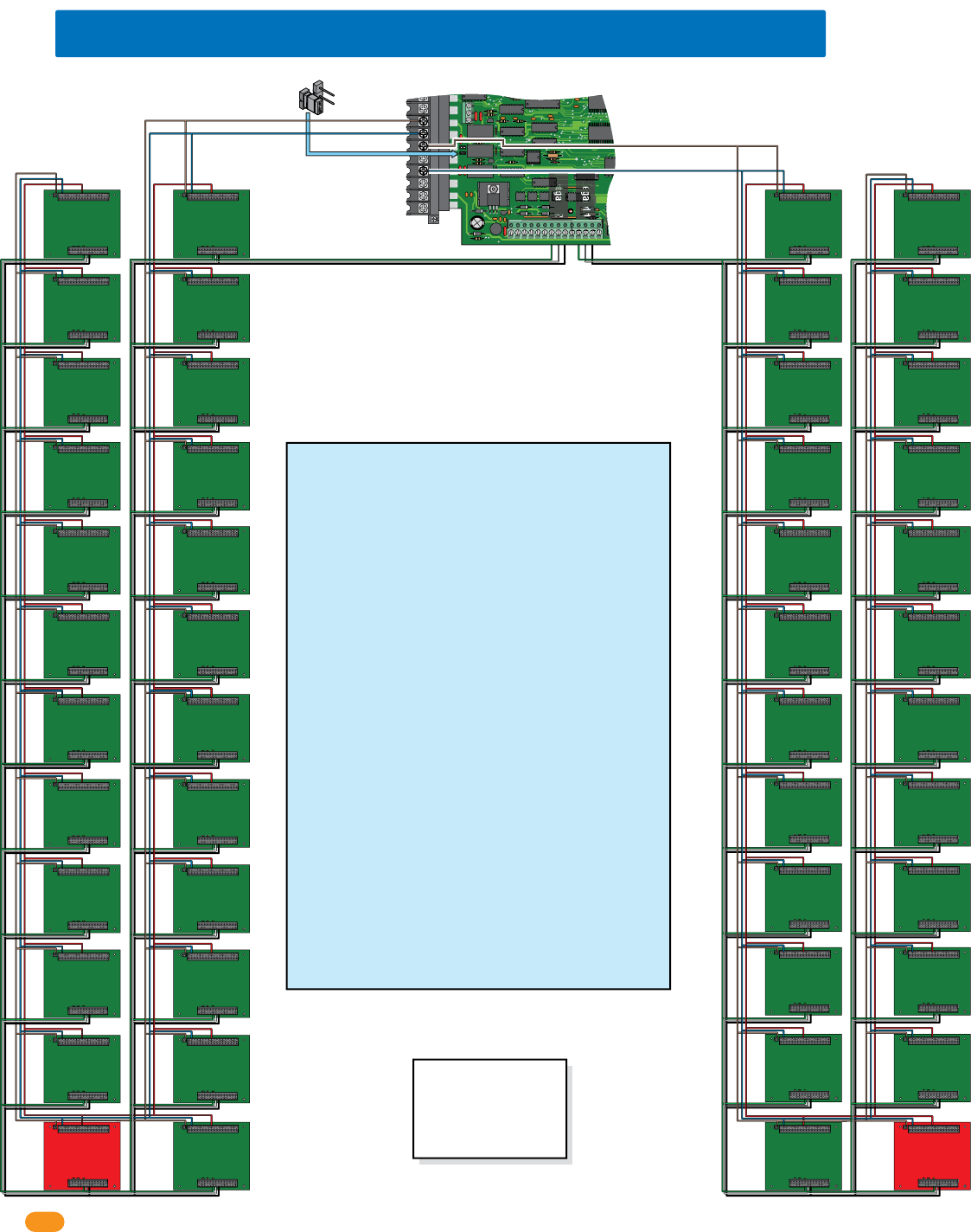
Main
Door/Gate
Relay 1
Relay 2
Zone Address
24 Boards maximum for Relay 2/Wiegand 2 ONLY (using board addresses 3-10)
24 Boards maximum for Relay 1/Wiegand 1 ONLY (using board addresses 11-18)
Zone Address Zone Address Zone Address Zone Address
Wiegand 1
Wiegand 2
Relay 0
Power
Power
Each board can be individually setup
for each access point depending on
what functions are desired. See
section 1.3 below for board options.
Zone addresses will need to be used
when using more than 8 boards per
Relay/Wiegand input (See section
1.6). 13+ jumper must be used
when using more than 12 boards
per Relay/Wiegand input, (See
section 1.8).
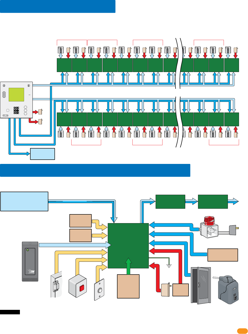
The diagram below shows the maximum number of tracker expansion boards that can be connected to the 1833, 1835,1837 and 1838.
Note: Wiegand 1 will activate Relay 1 and Wiegand 2 will activate Relay 2 at the access control system.
Existing
Alarm System
Tracker
Expansion
Board
2358-010
Local Alarm Separate
Alarm Power
Door Lock Gate Operator
External Alarm
Reset
Request
to Exit
Board Power
16.5 VAC, 20 VA
Ground
(Required)
12 GA. Wire
Battery
Back-Up
(Optional)
Gate
Operator 1
Data Input
Gate
Operator 2
Data Input
OR
Gate operator 2 data input:
DoorKing barrier gate operator only.
Gate operator 1 data input:
DoorKing slide, swing or overhead
operators only.
Alarm system outputs
are dry relay contacts.
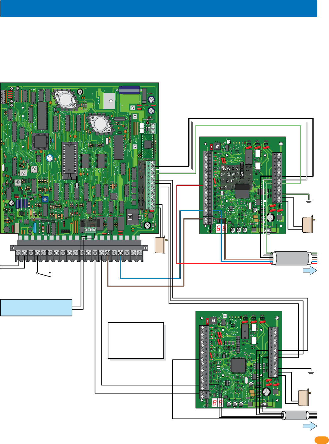
The diagram below shows the connections needed when all options (gate operator data, alarm outputs, door and reset switches, request to
exit, etc.) available with the 2358 tracker expansion board are utilized at an access point.
Tracker expansion board
input will accept most
wiegand 26, 30, 31-bit
access control devices.
Card Reader
Access Control Device
Auxiliary Relay
Alarm Relay
Output Relay
Next
Tracker Expansion
Board (Optional)
Next
Tracker Expansion
Board (Optional)
Communication Line
Optional Reader LED / Beeper Control
1.2 General System Layout
1.3 Tracker Expansion Board Layout Options
Wireless Kit
(Optional)
See Wireless
Instruction
Sheets
EXIT
PUSH TO
Access Control System
Relay 1/Wiegand 1
or
Relay 2/Wiegand 2
Door Contact
Switch
Access
Control
Device
Power
Access
Control
Device Power
Access
Control
Device Power
Access
Control
Device Power
Access
Control
Device Power
Access
Control
Device Power
Access
Control
Device Power
Access
Control
Device Power
Access
Control
Device Power
Access
Control
Device Power
Access
Control
Device
Power Access
Control
Device
Power Access
Control
Device
Power Access
Control
Device
Power Access
Control
Device
Power Access
Control
Device
Power Access
Control
Device
Power Access
Control
Device
Power Access
Control
Device
Power Access
Control
Device
Power
Tracker
Expansion
Board 1
Tracker
Expansion
Board 2
Tracker
Expansion
Board 3
Tracker
Expansion
Board 4
Tracker
Expansion
Board 5
Tracker
Expansion
Board 6
Tracker
Expansion
Board 7
Tracker
Expansion
Board 8
Tracker
Expansion
Board 21
Tracker
Expansion
Board 22
Tracker
Expansion
Board 23
Access
Control
Device Power
Access
Control
Device Power
Access
Control
Device Power
Tracker
Expansion
Board 24
Access
Control
Device
Power
Zone Address Zone Address
CALL
Z
A
Note: If card
reader has
additional
lighting for
outdoor use,
separate power
must be
provided.
PRESS
to RESET
Tracker
Expansion
Board 1
Tracker
Expansion
Board 2
Tracker
Expansion
Board 3
Tracker
Expansion
Board 4
Tracker
Expansion
Board 5
Tracker
Expansion
Board 6
Tracker
Expansion
Board 7
Tracker
Expansion
Board 8
Tracker
Expansion
Board 21
Tracker
Expansion
Board 22
Tracker
Expansion
Board 23
Tracker
Expansion
Board 24
2358-065-T-5-18
4
21
22
23
24
25
26
27
28
29
30
31
32
33
34
Gate Operator 1 – Data IN
Gate Operator 1 – Busy
Gate Operator 2 – Data IN
Gate Operator 2 – Busy
Gate Operator 1 & 2 – Common
Wiegand Input – Data 0
Wiegand Input – Data 1
Wiegand Common
12 VDC Wiegand Device Power
Tracker Expansion Board Busy
Gate Operator 1 Power Monitor
Gate Operator 1 Power Monitor
Gate Operator 2 Power Monitor
Gate Operator 2 Power Monitor
Door Ajar Input
Reset Alarm Input
Communication Relay Input
Request To Exit input
1
2
3
4
5
6
7
8
9
10
11
12
13
14
15
16
17
18
1 Gate Operator 1 – Data IN
Gate Operator 1 – Busy
Gate Operator 2 – Data IN
Gate Operator 2 – Busy
Gate Operator 1 & 2 – Common
Wiegand Input – Data 0
Wiegand Input – Data 1
Wiegand Common
12 VDC Wiegand Device Power
Tracker Expansion Board Busy
Gate Operator 1 Power Monitor
Gate Operator 1 Power Monitor
Gate Operator 2 Power Monitor
Gate Operator 2 Power Monitor
Door Ajar Input
Reset Alarm Input
Communication Relay Input
Request To Exit input
Communication data output to Wiegand 1 or 2 input (Auxiliary Terminal) on the access control system.
Connects to a local alarm.
Set relay to normally OPEN (NO) or normally CLOSED (NC) using relay jumpers on board.
Connects to a alarm reset button.
Connects to a request to exit button.
Connects to an existing building alarm system.
Set relay to normally OPEN (NO) or normally CLOSED (NC) using relay jumpers on board.
Connects to door control (electric strike, maglock) or gate control (gate operator).
Set relay to normally OPEN (NO) or normally CLOSED (NC) using relay jumpers on board.
Optional battery back-up allows the tracker expansion board to maintain operation during power out conditions.
Use .8 amp gel cell for single board P/N 1801-008, 3 amp gel cell for 4 boards max. P/N 1801-009.
Use a 16.5 VAC, 20 VA transformer (or UL listed equivalent) to power the tracker expansion board.
Max power wire run with 18 AWG wire is 100 feet; with 16 AWG wire is 200 feet. Wire polarity does NOT matter.
Gate operator 1 data input from DoorKing slide, swing or overhead gate operators.
Gate operator 2 data input from DoorKing barrier gate operator.
26, 30, 31-bit wiegand access device input ONLY. 500 ft max.
To an approved grounding source (Required).
Communication ONLY to other tracker expansion boards. DO NOT connect to access control system.
Communication to the access control system Relay 1 or 2 (Main Terminal) or other tracker expansion boards.
Monitors 24V AC/DC power from DoorKing slide, swing or overhead gate operators. Wire polarity does NOT matter.
Monitors 24V AC/DC power from DoorKing barrier gate operator. Wire polarity does NOT matter.
Magnetic Door Contact Switch:
Normally Closed: Switch contacts are held OPEN when the door is closed; switch contacts are CLOSED when the door is open.
Common
Card Reader LED/Beeper Control
19
20 Connects to a card reader with LED and beeper indicators. (Available on certain card readers)
Auxiliary Relay
Auxiliary Relay
Alarm Relay
Alarm Relay
Output Relay
Output Relay
Communication Data Output – Common
Communication Data Output – Data 1
Communication Data Output – Data 0
Battery Negative (-12VDC)
Battery Positive (+12VDC)
Earth Ground
16.5 VAC Input Power
16.5 VAC Input Power
Set relay jumper.
Set relay jumper.
Set relay jumper.
Power
Transformer
Battery
Back-Up
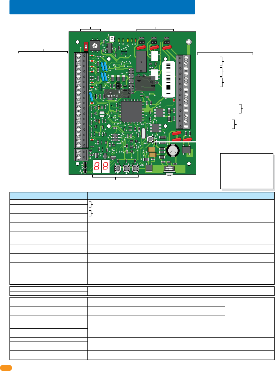
1.4 Tracker Expansion Board Overview
34
33
32
31
30
29
28
27
26
25
24
23
22
21
14
15
16
17
18
19
20
13
12
11
10
9
8
7
6
5
4
3
2
1
ON
1
0
BOARD ADDRESS
0
9
8
7
6
5
4
3
2
1
NC
OUTPUT
RELAY
NO
NC
ALARM
RELAY
NO
NC
AUX
RELAY
NO
ENT
RESET
2358-010
RF
DATA
RF
SECURE
RF
STATUS
CODE
SENT
CODE
GOOD
CODE
BAD
Wireless
Connection
See wireless
instructions.
13+ Jumper
See Section 1.8.
Board Relay Jumpers
See section 1.7.
Board Address (System Relays)
See sections 1.6 and 1.7.
Board Inputs
See below and next page.
Board Outputs & Power
See below and next page.
Reset Button
Press to reset the board.
Programming
See section 4.
Board Inputs Function / Connection
Common
Card Reader LED/Beeper Control
Note: Relay
contacts are
rated at 1A 30V
maximum.
Italic Text Note:
6-wire Communication line
REQUIRED connections.
See sections 3.2 thru 3.10.
Important Wireless Note:
Wireless kits DO NOT use the
#10, #17, #19, #27, #28 and
#29 communication line. Refer
to wireless instructions with
the wireless kits when using
wireless communication.
Auxiliary Relay
Auxiliary Relay
Alarm Relay
Alarm Relay
Output Relay
Output Relay
Communication Data Output – Common
Communication Data Output – Data 1
Communication Data Output – Data 0
Battery Negative (-12VDC)
Battery Positive (+12VDC)
Earth Ground
16.5 VAC Input Power
16.5 VAC Input Power
Do Not Connect To A Receptacle Controlled By A Switch.
Wire polarity does not matter.
2358-010 sn XXXX
Rev M

2358-065-T-5-18 5
1.5 Board Input Descriptions
Gate operator data inputs can only be used with DoorKing vehicular gate operators (see section 1.1). The tracker expansion board receives data (Terminals 1-5 and
11-14) from the gate operator control board, converts it to wiegand format, and then sends this wiegand data to the access control system where it is stored in the
transaction buffer. The data that is sent from the gate operator control board includes information such as gate operator cycle count (x100), if an obstruction was hit,
if an attempt was made to force the gate, etc. See the back of manual for a complete listing of all gate operator transactions. In PAMS applications, only one tracker
expansion board is required per traffic lane to monitor the gate operator activity of the slide, swing or overhead gate operator, and the parking gate operator. The
tracker expansion board will also monitor the 24 VAC power from the gate operator control board(s). When this power is removed, a “power out” transaction is sent
to the access control system.
Gate Operator Data Input
An alarm condition will exist anytime a controlled door is opened without access being granted by the access control system. The request to exit input (Terminals
18 & 19) allows the door to be opened without activating the tracker expansion board alarm relays, and will not cause the access system to report a forced
condition. The request to exit is typically used at a controlled access point to allow free exit to personnel. A “Push To Open” button, or a push bar, etc., is
connected to the request to exit input on the tracker expansion board. When this input is activated, the tracker expansion board
output relay
will activate causing
the door strike or magnetic lock to release allowing the door to be opened.
Request to Exit Input
The door ajar input (Terminals 8 & 15) monitors the status of a controlled access door through a magnetic (typical) door contact switch. This input tells the
tracker expansion board if the door is not fully closed, and will cause the alarm and auxiliary relays on the tracker expansion board to activate under certain
conditions (see section 3 and section 4). Typically, when the door is closed, the switch contacts are closed; when the door is open, the switch contacts are
open.
Door Ajar Input
The reset alarm input (Terminals 16 & 19) overrides the door ajar input allowing a door to be held open when necessary. When this input is activated, the
tracker expansion board will not activate its alarm or auxiliary relays even if the door ajar input is activated (see section 4).
Reset Alarm Input
The relay input (Terminals 17 & 19) is connected to the Relay 1 or Relay 2 in the access control system that activates when a valid device code is received by
the access control system. For example, when a card reader connected to the wiegand input on the tracker expansion board reads the card code, it inputs this
information to the tracker expansion board, which in turn sends the information to the access control system. The access control system then makes the
decision to grant or deny access. If access is denied, a transaction of the denial is made and nothing else happens. If access is granted, a transaction of the
access grant is made, and the access control system activates the communication relay. This relay output is connected to the tracker expansion board system
communication relay input, which then causes the tracker expansion board output relay to activate. The output relay activation will then open the controlled
door (or gate). If two or more tracker expansion boards are connected to the access system, only the output relay on the tracker expansion board that sent the
data will activate. The tracker expansion board relay strike time is set via the programming on the tracker expansion board (see section 4).
Communication Relay Input
(Communication Line to Access Control System’s Main Terminal Relay 1 or Relay 2)
Activation and operation of the AUXILIARY (Terminals 21-22) and ALARM (Terminals 23-24) relays is dependent on the programming on the tracker expansion board
(see section 4). Typically, the auxiliary relay is connected to a local alarm (bell, buzzer, light, etc.) and the alarm relay is connected to the buildings existing alarm
system. These relays provide a dry contact only.
A
uxiliary and Alarm Relays
The
Output Relay
(Terminals 25-26) activates on command from the access control system, or from a request to exit input. The
output relay
releases the door
strike (or magnetic lock) to allow entry or exit, or activates a gate operator if the tracker expansion board is used to control a vehicular gate.
This relay provides a dry
contact only.
Output Relay
ONLY used when MORE that 12 boards are used per wiegand/relay wire run
(see section 1.8)
.
13+ Jumper
All data received at the wiegand input terminals and the gate tracker terminals is sent to the access control system in 26, 30, 31-bit wiegand format from the
wiegand output (Terminals 27-28-29).
Communication Data Output
(Communication Line to Access Control System’s Auxiliary Terminal Wiegand 1 or Wiegand 2)
Tracker expansion boards can accept wiegand input data from most devices that output their data in a wiegand format. When using 30 or 31-bit wiegand
devices, the system will only recognize facility code 255 and lower. An access control device (a card reader for example) is connected to the tracker expansion
board (Terminals 6-7-8-9). When the tracker expansion board receives the wiegand data from the access device, it sends the data to the access control system
where the decision to grant or deny access is made. At the same time, a report is made of this activity and is stored in the transaction buffer. Two access control
devices may be connected to a single tracker expansion board, however each device will report the same location in the transaction report when connected in
this method and each device will activate the same door (or gate). This may be preferable in some instances. For example, if a vehicular gate uses both a card
reader and an RF receiver for resident access, each of these devices can be connected in parallel. Each device will activate the gate (door) that the output relay
of the tracker expansion board is connected to, and each device will appear in the transaction report with the name assigned to the tracker expansion board in
the software (“Main Gate”, for example, Refer to the Dual Door Mode).
A
ccess Control Device Input (26, 30, 31-Bit Wiegand)
2358-065-T-5-18
6
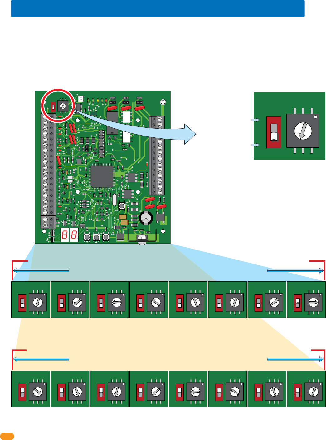
1.6 Setting Board Address (Software - System Relay)
Set dial numbers
accordingly with switch.
34
33
32
31
30
29
28
27
26
25
24
23
22
21
14
15
16
17
18
19
20
13
12
11
10
9
8
7
6
5
4
3
2
1
ON
1
0
BOARD ADDRESS
0
9
8
7
6
5
4
3
2
1
NC
OUTPUT
RELAY
NO
NC
ALARM
RELAY
NO
NC
AUX
RELAY
NO
ENT
RESET
2358-010
RF
DATA
RF
SECURE
RF
STATUS
CODE
SENT
CODE
GOOD
CODE
BAD
ON
OFF
1
0
BOARD ADDRESS
0
9
8
7
6
5
4
3
2
1
ON
OFF
1
0
BOARD ADDRESS
0
9
8
7
6
5
4
3
2
1
ON
OFF
1
0
BOARD ADDRESS
0
9
8
7
6
5
4
3
2
1
ON
OFF
1
0
BOARD ADDRESS
0
9
8
7
6
5
4
3
2
1
ON
OFF
1
0
BOARD ADDRESS
0
9
8
7
6
5
4
3
2
1
ON
OFF
1
0
BOARD ADDRESS
0
9
8
7
6
5
4
3
2
1
ON
OFF
1
0
BOARD ADDRESS
0
9
8
7
6
5
4
3
2
1
ON
OFF
1
0
BOARD ADDRESS
0
9
8
7
6
5
4
3
2
1
ON
OFF
1
0
BOARD ADDRESS
0
9
8
7
6
5
4
3
2
1
ON
OFF
1
0
BOARD ADDRESS
0
9
8
7
6
5
4
3
2
1
ON
OFF
1
0
BOARD ADDRESS
0
9
8
7
6
5
4
3
2
1
ON
OFF
1
0
BOARD ADDRESS
0
9
8
7
6
5
4
3
2
1
ON
OFF
1
0
BOARD ADDRESS
0
9
8
7
6
5
4
3
2
1
ON
OFF
1
0
BOARD ADDRESS
0
9
8
7
6
5
4
3
2
1
ON
OFF
1
0
BOARD ADDRESS
0
9
8
7
6
5
4
3
2
1
ON
OFF
1
0
BOARD ADDRESS
0
9
8
7
6
5
4
3
2
1
ON
OFF
1
0
BOARD ADDRESS
0
9
8
7
6
5
4
3
2
1
Note: Start at board address 3, the software reserves board address (system relay) 0, 1 and 2 for the access control system ONLY.
Note: Board Addresses 0, 1, 2 & 19 will not generate a wiegand signal.
Example: The switch is OFF and
the dial is set to 3, so the Board
Address is 3. The software uses
the board address as the System
Relay, this means the System
Relay for this board is 3. See
below for all board settings.
Switch
Maximum HARD wire run between tracker expansion boards (up to 24 boards) is 4000 feet TOTAL,
see section 2 for more information about HARDwiring limitations.
Dial Numbers
Maximum HARD wire run between tracker expansion boards (up to 24 boards) is 4000 feet TOTAL,
see section 2 for more information about HARDwiring limitations.
IMPORTANT: DO NOT
set the board address
to 0, 1, 2 or 19.
IMPORTANT: ONLY 8
board addresses can
be used for EACH
wiegand/relay run.
Switch MUST be ON (1) for
board addresses 10 thru 18.
(Dial number +10).
Switch MUST be OFF (0) for
board addresses 3 thru 9.
(Dial number only).
Board Address 3
System Relay 3
Board Address 4
System Relay 4
Board Address 5
System Relay 5
Board Address 6
System Relay 6
Board Address 7
System Relay 7
Board Address 8
System Relay 8
Board Address 9
System Relay 9
Board Address 10
System Relay 10
Board Address 11
System Relay 11
Board Address 12
System Relay 12
Board Address 13
System Relay 13
Board Address 14
System Relay 14
Board Address 15
System Relay 15
Board Address 16
System Relay 16
Board Address 17
System Relay 17
Board Address 18
System Relay 18
Board addresses 11 thru 18 MUST connect to Relay 1/Wiegand 1 on the access control system
Board addresses 3 thru 10 MUST connect to Relay 2/Wiegand 2 on the access control system
When using tracker expansion boards connected to a single access control system, the board addresses on EACH tracker expansion board
should be set so that the Remote Account Manager for Windows (V 6.3i or newer only) software can identify each tracker expansion
board. The software reserves board address 0, 1 and 2 for the access control system. Tracker expansion board address starts with relay
address 3 (see below). IMPORTANT: The software uses the board address number for the System Relay number.
“Zone” Addresses: Board addresses can be set the same (functions as “zones”), but the system’s “tracking” capability will NOT be able
to distinguish SPECIFIC access point activity. Two or more boards with the same board address will be tracked and logged as “zone number”
but not a specific location for that activity. For example, if you have 4 card readers in different locations in a building, and all have the same
board addresses, the software would track that a card reader in the “zone number” was used, but not which specific location it was used.
Zones can be used for a restricted area with multiple entrances inside the complex such as a pool area/tennis courts or community center.
Zones are not recommended if detailed tracker activity reports are required.
2358-065-T-5-18 7
Relay 1
Main Terminal
ONLY Board Addresses 3-10 connect to Relay 2/Wiegand 2 (24 Boards max)
ONLY Board Addresses 11-18 connect to Relay 1/Wiegand 1 (24 Boards max)
Relay 2
Main Terminal
Note: Relay 2 jumper
set to normally OPEN.
NC
NO
16AC
2019181612 13 14 15 17
16ACBAT1NO1NC1C2RY2CA
Auxiliary Terminal
NO NC C
12345678910 11 12 13 14
Main Terminal
Access
Control
System
Board
Tracker Expansion Board
Wiegand 1 (Aux Terminal)
Wiegand 2 (Aux Terminal)
Relay 2
Jumper
“NO”
Relay 0
NC
NO
RING
HF
1816
HS
ON
CLK
SEN
SPK
VOL
FEED
BACK
RS 232
ELEVATOR
MIC
VOL
OFF
KEYPAD
321
321
321
MASTER
CODE
16AC16ACBAT1NO1NC1C2RY2CAZIMC
5VDCIMDSPKRCOMMICPSWCGNDPHONE
1
2
3
1234 5 67891011121314
1
2
3
4
5
6
Relay 0
Relay 2 Jumper
NO NC C
Access Control System Main Terminal
The models 1833, 1835, 1837 and 1838 access control systems each have THREE relays (Relay 0, 1, and 2). When the tracker expansion
boards is added to this system, the Output Relay on the tracker expansion boards (Terminals 25-26) are identified in the software by the
board address, beginning with board address 3 = System Relay 3 (System Relays 0, 1 and 2 are reserved for the access control board
relays ONLY in the software).
Each of the 3 relays on the tracker expansion board can be set to either Normally Open (NO) or Normally Closed (NC) by setting the board
relay jumper to the desired configuration. Typically, normally OPEN is used.
When tracker expansion boards are used to expand the access control system, Relays 1 and 2 on the access control system circuit board are
used as tracker expansion communication relays. Relay 2 MUST connect to tracker expansion board addresses 3-10 (system relays 3-10)
and Relay 1 MUST connect to tracker expansion board addresses 11-18 (system relays 11-18).
If both Relay 1 and Relay 2 are used to control tracker expansion boards, Relay 0 is used as the Primary Relay that will open the main door or
gate when the resident pushes “9” on their telephone.
Relay 1
Relay 2
Board Relay Jumpers
SOFTWARE
INSTALLED
Your PC connected to the access control system board
(RS-232 terminal).
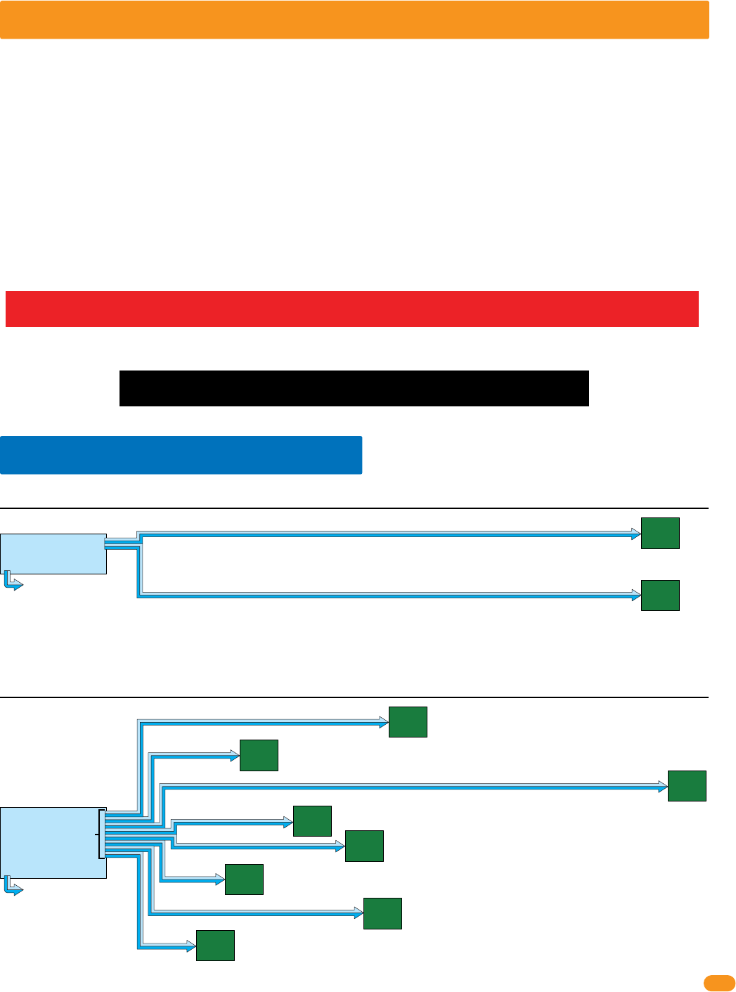
System Relays for the tracker expansion boards are
identified in the DKS software sequentially by the board
address, beginning with board address 3 = System Relay 3
and ending with board address 18 = System Relay 18.
Relays 0, 1 and 2 are “Physically” located on the access
control board. They are identified in the DKS software as
system relays 0, 1 and 2.
Zone addresses CAN be used but MUST be used when
more than 8 boards are required for a Relay/Wiegand input.
See previous page about zone addresses.
Main
Door/Gate
Relay 0
1.7 Relay Identification (Software - System Relay)
34
33
32
31
30
29
28
27
26
25
24
23
22
21
14
15
16
17
18
19
20
13
12
11
10
9
8
7
6
5
4
3
2
1
ON
1
0
BOARD ADDRESS
0
9
8
7
6
5
4
3
2
1
NC
OUTPUT
RELAY
NO
NC
ALARM
RELAY
NO
NC
AUX
RELAY
NO
ENT
RESET
2358-010
RF
DATA
RF
SECURE
RF
STATUS
CODE
SENT
CODE
GOOD
CODE
BAD
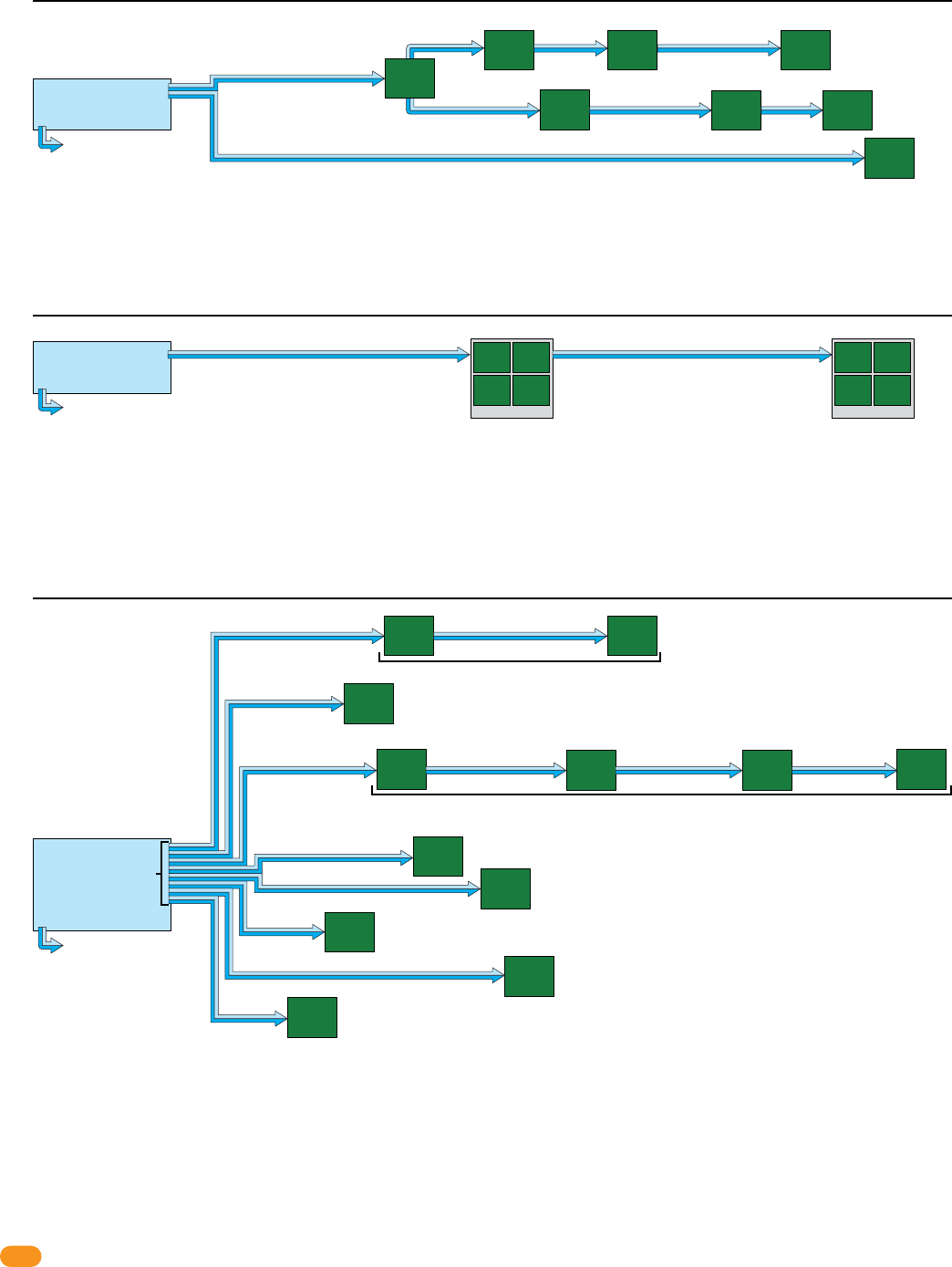
Remote Account Manager Software for Windows System Relay Identification
Aux Relay
Alarm Relay
Output Relay
(System Relay)
RS-232
Set relay 2 jumper NO or NC.
Important Wireless Note:
Wireless kits ARE NOT
wired like this. Refer to
wireless instructions with
the wireless kits when using
wireless communication.
Tracker
Expansion
Board at
access point
Board
Address 3
Tracker
Expansion
Board at
access point
Board
Address 4
Tracker
Expansion
Board at
access point
Board
Address 5
Tracker
Expansion
Board at
access point
Board
Address 6
Tracker
Expansion
Board at
access point
Board
Address 6
Tracker
Expansion
Board at
access point
Board
Address 7
Tracker
Expansion
Board at
access point
Board
Address 8
Tracker
Expansion
Board at
access point
Board
Address 8
Tracker
Expansion
Board at
access point
Board
Address 9
Tracker
Expansion
Board at
access point
Board
Address 9
Tracker
Expansion
Board at
access point
Board
Address 10
Tracker
Expansion
Board at
access point
Board
Address 10
Tracker
Expansion
Board at
access point
Board
Address 11
Tracker
Expansion
Board at
access point
Board
Address 11
Tracker
Expansion
Board at
access point
Board
Address 12
Tracker
Expansion
Board at
access point
Board
Address 12
Tracker
Expansion
Board at
access point
Board
Address 13
Tracker
Expansion
Board at
access point
Board
Address 14
Tracker
Expansion
Board at
access point
Board
Address 14
Tracker
Expansion
Board at
access point
Board
Address 15
Tracker
Expansion
Board at
access point
Board
Address 16
Tracker
Expansion
Board at
access point
Board
Address 17
Tracker
Expansion
Board at
access point
Board
Address 17
Tracker
Expansion
Board at
access point
Board
Address 18
Zone AddressZone AddressZone AddressZone Address
Zone Address Zone Address Zone Address Zone Address
2358-065-T-5-18
8
34
33
32
31
30
29
28
27
26
25
24
23
22
21
14
15
16
17
18
19
20
13
12
11
10
9
8
7
6
5
4
3
2
1
ON
1
0
BOARD ADDRESS
0
9
8
7
6
5
4
3
2
1
NC
OUTPUT
RELAY
NO
NC
ALARM
RELAY
NO
NC
AUX
RELAY
NO
ENT
RESET
2358-010
RF
DATA
RF
SECURE
RF
STATUS
CODE
SENT
CODE
GOOD
CODE
BAD
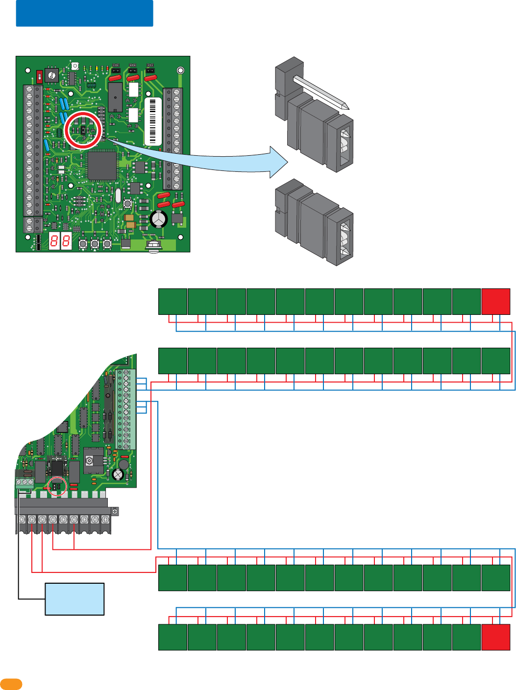
1.8 13+ Jumper
DO NOT use the 13+ jumper for the FIRST 12 boards in the 24 board total for each relay/wiegand connection. At least ONE board on the
SECOND 12 boards MUST use the 13+ jumper for each relay/wiegand connection. Note: Rev M or higher 2358 board.
13+ jumper USED - Jumpered
13+ jumper
USED
13+ jumper
USED
13+ jumper NOT used
Factory Setting - NOT Jumpered
13+ jumper NOT used
13+ jumper NOT used
Relay 1
Main Terminal
Relay 2/Wiegand 2 (24 Boards max)
Relay 2
Main Terminal
Note: Relay 2 jumper
set to normally OPEN.
NC
NO
16AC
2019181612 13 14 15 17
16ACBAT1NO1NC1C2RY2CA
Auxiliary Terminal
NO NC C
12345678910 11 12 13 14
Main Terminal
Access
Control
System
Board
Wiegand 2 (Aux Terminal)
Relay 2
Jumper
“NO”
Relay 0
Main
Door/Gate
Relay 0
Tracker
Expansion
Board 1
Tracker
Expansion
Board 2
Tracker
Expansion
Board 3
Tracker
Expansion
Board 4
Tracker
Expansion
Board 5
Tracker
Expansion
Board 6
Tracker
Expansion
Board 7
Tracker
Expansion
Board 8
Tracker
Expansion
Board 9
Tracker
Expansion
Board 10
Tracker
Expansion
Board 11
Tracker
Expansion
Board 12
Tracker
Expansion
Board 24
Tracker
Expansion
Board 23
Tracker
Expansion
Board 22
Tracker
Expansion
Board 21
Tracker
Expansion
Board 20
Tracker
Expansion
Board 19
Tracker
Expansion
Board 18
Tracker
Expansion
Board 17
Tracker
Expansion
Board 16
Tracker
Expansion
Board 15
Tracker
Expansion
Board 14
Tracker
Expansion
Board 13
Relay 1/Wiegand 1 (24 Boards max)
Wiegand 1 (Aux Terminal)
Tracker
Expansion
Board 24
Tracker
Expansion
Board 23
Tracker
Expansion
Board 22
Tracker
Expansion
Board 21
Tracker
Expansion
Board 20
Tracker
Expansion
Board 19
Tracker
Expansion
Board 18
Tracker
Expansion
Board 17
Tracker
Expansion
Board 16
Tracker
Expansion
Board 15
Tracker
Expansion
Board 14
Tracker
Expansion
Board 13
Tracker
Expansion
Board 1
Tracker
Expansion
Board 2
Tracker
Expansion
Board 3
Tracker
Expansion
Board 4
Tracker
Expansion
Board 5
Tracker
Expansion
Board 6
Tracker
Expansion
Board 7
Tracker
Expansion
Board 8
Tracker
Expansion
Board 9
Tracker
Expansion
Board 10
Tracker
Expansion
Board 11
Tracker
Expansion
Board 12
IMPORTANT: DO NOT use the 13+ jumper for ANY of the FIRST 12 boards.
More than one 13+ jumper can be used on the SECOND 12 boards or at
least ONE 13+ jumper has to be used on ANY of the SECOND 12 boards.
2358-010 sn XXXX
Rev M
IMPORTANT: ONLY 8 board addresses can be used for EACH wiegand/relay
run. If more than 8 boards are being used, zone addresses MUST be used,
see section 1.6.
2358-065-T-5-18 9
SECTION 2 - INSTALLATION
The location of the tracker expansion board(s) is dependent on the application that it is being used. Tracker expansion boards
can be installed in selected card reader housings, or they can be installed in their own enclosure (enclosures are optional and
not included with the tracker expansion board). DoorKing has two enclosures available for this purpose. The small housing will
hold a single tracker expansion board and the large housing can hold up to four tracker expansion boards. In addition, the large
housing has convenience outlets to power up to four accessory transformers.
Selected models of proximity card readers are available with an enclosure that has ample room for a tracker expansion board to
be mounted inside the housing. This simplifies the installation of the card reader used with the tracker expansion board.
HARDwire Run: Up to 24 tracker expansion boards can be wired to EACH of the TWO communication
lines available (relay 2/wiegand 2 and relay 1/wiegand 1) at the access control system.
A second communication
line can be wired with the
same wiring limitations shown in examples if desired.
tracker
expansion
board
address 4
tracker
expansion
board
address 3
2000 ft
2000 ft
access control system
NO more boards can be connected to reley 2/wiegand 2 communication line.
relay 2/wiegand 2
relay 1/wiegand 1
farthest
board
2000 ft
away
farthest
board
2000 ft
away
Example 1: 4000 ft total, ONLY one HARDwired communication line shown. 2 boards are connected to relay 2/wiegand 2.
Communication line to boards are
connected in parallel. Allows “teeing”
of communication cable for optimal
cable routing.
A second communication
line can be added with same
wiring limitations shown in
examples if desired.
tracker
expansion
board
address 3
tracker
expansion
board
address 4 tracker
expansion
board
address 5
tracker
expansion
board
address 6 tracker
expansion
board
address 7
tracker
expansion
board
address 8
tracker
expansion
board
address 9
tracker
expansion
board
address 10
All boards are less than 2000 ft away from access control system.
500 ft
200 ft
1900 ft
300 ft
400 ft
150 ft
450 ft
100 ft
access control system
relay 2/wiegand 2
relay 1/wiegand 1
Example 2: 4000 ft total, ONLY one HARDwired communication line shown. 8 boards are connected to relay 2/wiegand 2.
Communication line to boards are connected
in parallel. Allows “teeing” of communication
cable for optimal cable routing.
Relay/Wiegand Note:
Relay 2/wiegand 2 MUST be connected to tracker
expansion board addresses 3 thru 10.
Relay 1/wiegand 1 connects to tracker expansion board
addresses 11 thru 18 if that many boards are desired.
Zone addresses can be used if desired.
Zone addresses can be used if desired.
IMPORTANT Wireless communication maximum distances between the access control system and tracker expansion
boards will vary from the HARDwire run distances illustrated below. See the instruction sheets in the wireless kits and the
Layout and Start-Up Procedure for the correct distances between the hardware when using wireless communication.
IMPORTANT: The maximum distance for a tracker expansion board HARDwire run is 4000 feet TOTAL (1 to 24 boards
can be in a HARDwire run). The farthest boards can be NO more than 2000 feet away from the access control system.
This access control equipment must be installed inside of a controlled, protected or
restricted area to comply with UL 294 certification. See page 1 for more information.
2.1 System Layout Examples
2358-065-T-5-18
10
A second communication
line can be added with same
wiring limitations shown in
examples if desired.
tracker
expansion
board
address 3
tracker
expansion
board
address 4
tracker
expansion
board
address 5
tracker
expansion
board
address 5
tracker
expansion
board
address 6 tracker
expansion
board
address 7
tracker
expansion
board
address 8
tracker
expansion
board
address 9
tracker
expansion
board
address 10
All boards are less than 2000 ft away from access control system.
Zone addresses can be used if desired.
250 ft 250 ft
Zone Addresses
200 ft
500 ft 600 ft 400 ft 400 ft
300 ft
400 ft
150 ft
450 ft
100 ft
access control system
tracker
expansion
board
address 3
tracker
expansion
board
address 5
tracker
expansion
board
address 5
relay 2/wiegand 2
relay 1/wiegand 1
Example 5: 4000 ft total, ONLY one HARDwired communication line shown. 12 boards with “Zones” are connected to relay 2/wiegand 2.
Communication line to boards are connected
in parallel. Allows “teeing” of communication
cable for optimal cable routing.
Relay/Wiegand Note:
Relay 2/wiegand 2 MUST be connected to tracker
expansion board addresses 3 thru 10.
Relay 1/wiegand 1 connects to tracker expansion board
addresses 11 thru 18 if that many boards are desired.
Wiring More Than 8 Boards Note:
Use 6 conductor stranded with overall shield - 18 gauge.
ONLY use 18 gauge when wiring more than 8 boards.
DO NOT connect shield to 2358-010 board common.
DO NOT use twisted pair.
Zone Addresses
tracker
expansion
board
address 7
tracker
expansion
board
address 8
tracker
expansion
board
address 9
tracker
expansion
board
address 10
Quad Box
A second communication line can be added with same
wiring limitations shown in examples if desired.
farthest
board
2000 ft
away
farthest
board
1900 ft
away
access control system
relay 2/wiegand 2
relay 1/wiegand 1
Example 4: 2000 ft total, ONLY one HARDwired communication line shown. 8 boards are connected to relay 2/wiegand 2.
1000 ft tracker
expansion
board
address 3
tracker
expansion
board
address 4
tracker
expansion
board
address 5
tracker
expansion
board
address 6
Quad Box
1000 ft
IMPORTANT Wireless communication maximum distances between the access control system and tracker expansion
boards will vary from the HARDwire run distances illustrated above. See the instruction sheets in the wireless kits and the
Layout and Start-Up Procedure for the correct distances between the hardware when using wireless communication.
tracker
expansion
board
address 4
tracker
expansion
board
address 5
tracker
expansion
board
address 7
tracker
expansion
board
address 10
500 ft
500 ft
2000 ft
100 ft 100 ft
access control system
A second communication
line can be added with the
same wiring limitations shown in examples if desired.
relay 2/wiegand 2
relay 1/wiegand 1
tracker
expansion
board
address 6
farthest board
900 ft away
200 ft
100 ft
tracker
expansion
board
address 8
tracker
expansion
board
address 9
farthest
board
1600 ft
away
farthest
board
2000 ft
away
500 ft
tracker
expansion
board
address 3
Example 3: 4000 ft total, ONLY one HARDwired communication line shown. 8 boards are connected to relay 2/wiegand 2.
Communication line to boards are
connected in parallel. Allows “teeing”
of communication cable for optimal
cable routing.
Zone addresses can be used if desired.
2358-065-T-5-18 11
A second communication
line can be added with same
wiring limitations shown in
examples if desired.
tracker
expansion
board
address 3
tracker
expansion
board
address 6
tracker
expansion
board
address 7
tracker
expansion
board
address 8
tracker
expansion
board
address 9
tracker
expansion
board
address 11
All boards are 2000 ft or less away from access control system.
250 ft 250 ft 1500 ft
Zone Addresses
50 ft
55 ft
55 ft
400 ft
50 ft 130 ft
access control system
tracker
expansion
board
address 3
relay 2/wiegand 2
relay 1/wiegand 1
Example 7: 4000 ft total,
ONLY one HARDwired communication line shown. 24 boards with “Zones” and “13+ Jumper” are connected to relay 2/wiegand 2.
Communication line to boards are connected
in parallel. Allows “teeing” of communication
cable for optimal cable routing.
Relay/Wiegand Note:
Relay 2/wiegand 2 MUST be connected to tracker
expansion board addresses 3 thru 10.
Relay 1/wiegand 1 connects to tracker expansion board
addresses 11 thru 18 if that many boards are desired.
Wiring More Than 8 Boards Note:
Use 6 conductor stranded with overall shield - 18 gauge. ONLY use 18
gauge when wiring more than 8 boards.
Use 13+ Jumper on at least ONE board when using MORE than 12 boards.
DO NOT connect shield to 2358-010 board common.
DO NOT use twisted pair.
tracker
expansion
board
address 4
tracker
expansion
board
address 4
tracker
expansion
board
address 4
tracker
expansion
board
address 4
Quad Box
farthest
board
2000 ft
away
100 ft 1000 ft
Zone Addresses
tracker
expansion
board
address 9
Zone Addresses
Zone Addresses
tracker
expansion
board
address 10
tracker
expansion
board
address 10
tracker
expansion
board
address 10
tracker
expansion
board
address 10
Quad Box
farthest
board
1500 ft
away
Zone Addresses
tracker
expansion
board
address 12
tracker
expansion
board
address 12
tracker
expansion
board
address 12
tracker
expansion
board
address 12
Quad Box
farthest
board
180 ft
away
tracker
expansion
board
address 5
tracker
expansion
board
address 5
100 ft 20 ft 20 ft 20 ft
tracker
expansion
board
address 5
tracker
expansion
board
address 5
Zone Addresses
farthest
board
160 ft
away
IMPORTANT Wireless communication maximum distances between the access control system and tracker expansion
boards will vary from the HARDwire run distances illustrated above. See the instruction sheets in the wireless kits and the
Layout and Start-Up Procedure for the correct distances between the hardware when using wireless communication.
Use 13+ Jumper
relay 2/wiegand 2
relay 1/wiegand 1
Individual addresses can be used if desired.
Individual addresses can be used if desired.
tracker
expansion
board
address 3
tracker
expansion
board
address 3
500 ft 600 ft 400 ft 500 ft
tracker
expansion
board
address 3
tracker
expansion
board
address 3
tracker
expansion
board
address 4
tracker
expansion
board
address 4
500 ft 600 ft 400 ft 500 ft
tracker
expansion
board
address 4
tracker
expansion
board
address 4
Zone Addresses
Zone Addresses
A second communication
line can be wired with the
same wiring limitations shown
in examples if desired.
access control system
NO more boards can be connected to reley 2/wiegand 2 communication line.
Example 6: 4000 ft total, ONLY one HARDwired communication line shown. 8 boards
with “Zones”
are connected to relay 2/wiegand 2.
Communication line to boards are connected in
parallel. Allows “teeing” of communication cable
for optimal cable routing.
farthest
board
2000 ft
away
farthest
board
2000 ft
away
2358-065-T-5-18
12
Supply
Ground
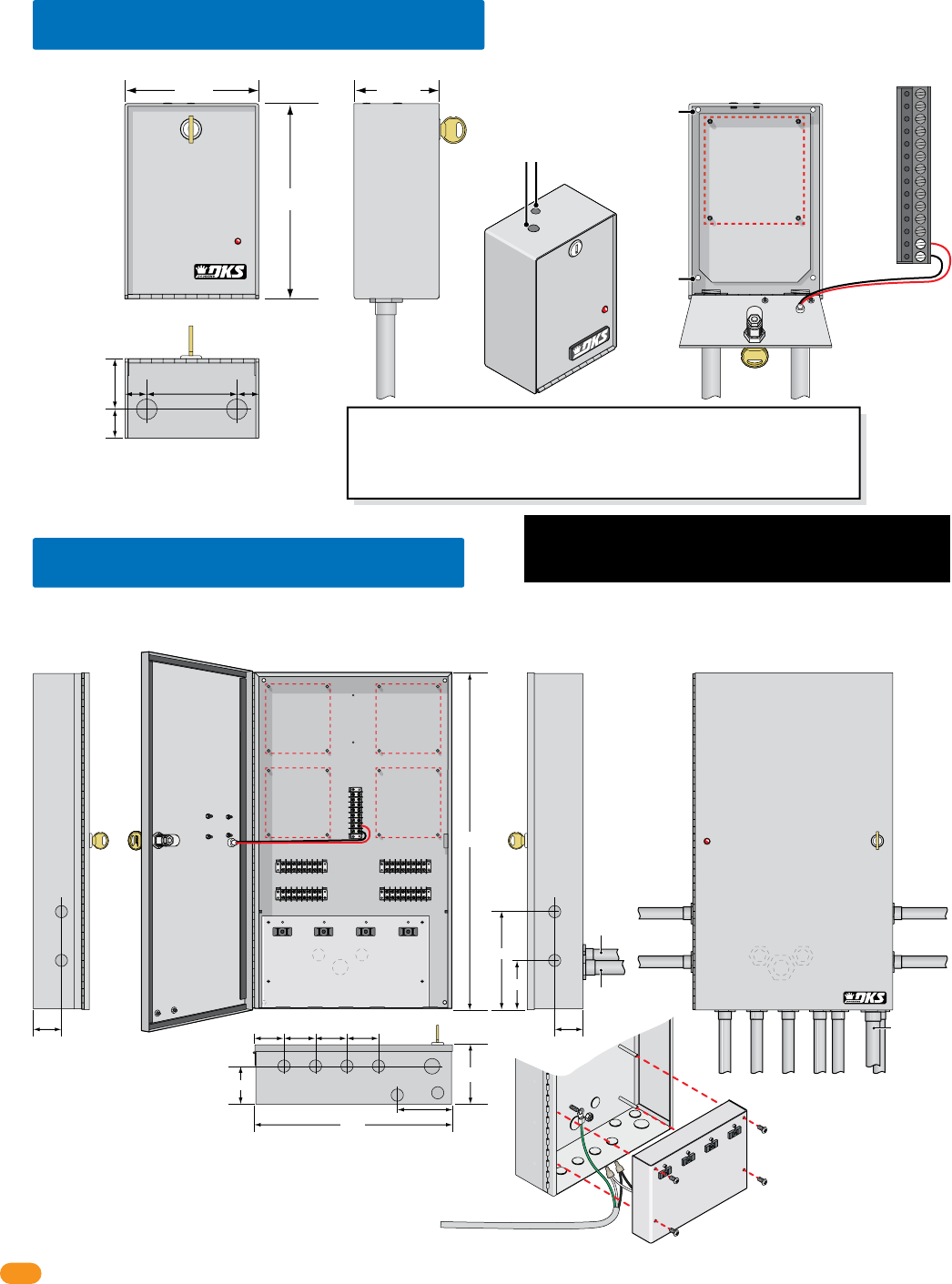
Optional quad box enclosure (P/N 2351-081) provides a lockable weather resistant housing for up to four (4) tracker expansion boards.
Includes four (4) terminals and four (4) convenience outlets for power transformers. You may power up to four (4) tracker expansion boards from a Single
16.5 VAC, 50 VA power transformer (P/N 1508-060). See section 3.9 for quad box wiring information.
2.3 Quad Board Enclosure
4”
3.5”
7”
2.75”
24”
14”
2” 2”
Conduit Placement
Options
(5) 8-Pin Terminals
Communication
Lines
Terminal
Access Point TerminalAccess Point Terminal
Access Point TerminalAccess Point Terminal
Mounting Hole Mounting Hole
Mounting HoleMounting Hole
Tracker
Expansion
Board
Mount
Tracker
Expansion
Board
Mount
Tracker
Expansion
Board
Mount
Tracker
Expansion
Board
Mount
3/4”
3/4” 3/4”
3/4” 3/4”
3/4”
2” 2.5” 2.5” 2.5”
3/4”
3/4”
3/4”
3/4”
3/4”
3/4”
3/4”
3/4”
4”
1”
1”
1”
3/4” Conduit 3/4” Conduit
3/4”
Conduit
115 VAC Input Power Wire (not supplied)
Connect White to White,
Black to Black and
Green to Supply Ground
on quad box.
Remove power panel with 4 screws.
1” Conduit
1”
Conduit
3/4”
Conduit
Note: Remove convenience outlets power
panel to access knock-outs and mounting hole. Note: Conduit entering in back of housing
knock-outs
knock-outs
knock-outs
Back of Housing
Battery Back-Up Note:
A 12 VDC, 3 amp-hour battery
(P/N 1801-009) can be used to
supply back-up power to four
(4) tracker expansion boards.
Optional single enclosure (P/N 2351-080) provides a lockable, weather resistant housing for a single tracker expansion board.
2.2 Single Board Enclosure
Tracker
Expansion
Board
Mount
3/4” Conduit
Placement
1” 1”3.75”
1.25”
2.375”
3/4”
Knock-outs
Mounting
Hole
Battery Back-Up Note: A 12 VDC, .8 amp-hour
battery (P/N 1801-008) can be used to supply
back-up power to a single tracker expansion board.
Important Wireless Note: DO NOT remove antenna plugs if NOT using a antenna that screws
into the top of the enclosure for wireless communication.
If using an external antenna for wireless communication that uses a coax cable, run it out of
the BOTTOM of the enclosure. DO NOT run coax cable out of the top of the enclosure, it will
leak and cause damage to the circuit board.
8.75”
5.75” 3.625”
Mounting Hole
Optional Screw On Antenna Mounts
for wireless kits ONLY.
Wire LED to
terminals
#33 and #34
on tracker
board.
Connect 115 VAC Power
Power Panel
#33 16.5 VAC
#34 16.5 VAC
This access control equipment must be installed inside of a
controlled, protected or restricted area to comply with UL 294
certification. See page 1 for more information.
2358-065-T-5-18 13
Input:
120 V 60 Hz
Output:
16.5 VAC 20 VA
SECTION 3 - HARDWIRING
Plan your HARDwire runs before starting the installation. Use proper wire for the wiegand lines, power wires, and be sure that
the system is properly grounded. Check all local building ordinances and building codes prior to installing this system. Be sure
your installation is in compliance with local codes.
3.1 General HARDwiring Information
• Do Not Connect Power To A Receptacle Controlled By A Switch.
• Use only the supplied power transformers (16.5 VAC, 20 VA) or UL listed equivalent to power the tracker expansion board. You may
power up to four (4) tracker expansion boards from a single 16.5 VAC, 50 VA power transformer.
• Use 18 AWG wire for power wire runs up to 100 feet. Use 16 AWG wire for power wire runs up to 200 feet. It is advisable to keep
power wire runs as short as possible. Wire polarity does not matter.
• Do not power any other devices (electric strikes, magnetic locks) from the tracker expansion board power transformer. These devices
must be powered from their own power supply.
• Proper grounding of the system is required. To be effective, ground connections should be made with a minimum 12 AWG wire with
a ground point within 10-feet of the access control system. The ground point must be an electrical panel ground buss, a metallic cold
water pipe that runs in the earth, or a grounding rod driven at least 10-feet into the soil. If there are several components in the access
control system within close proximity to each other, you should consider using a single-point ground system. Check with your
building department for specific grounding guidelines as soil conditions and grounding requirements differ depending on your
geographical location.
• Surge suppressors can significantly reduce the chance of component failure because of static charges or surges. We recommend
using both high and low voltage surge suppressors to help protect equipment from damage. High voltage suppressor P/N 1879-010;
low voltage suppressor P/N 1878-010.
• A 12 VDC, 3 amp-hour battery (P/N 1801-009) can be used to supply back-up power to four (4) tracker expansion boards. Use a
12 VDC, .8 amp-hour battery (P/N 1801-007) to back-up a single tracker expansion board. Battery back-up power is optional and
not required for normal tracker expansion board operation.
• Be sure to color code all wires.
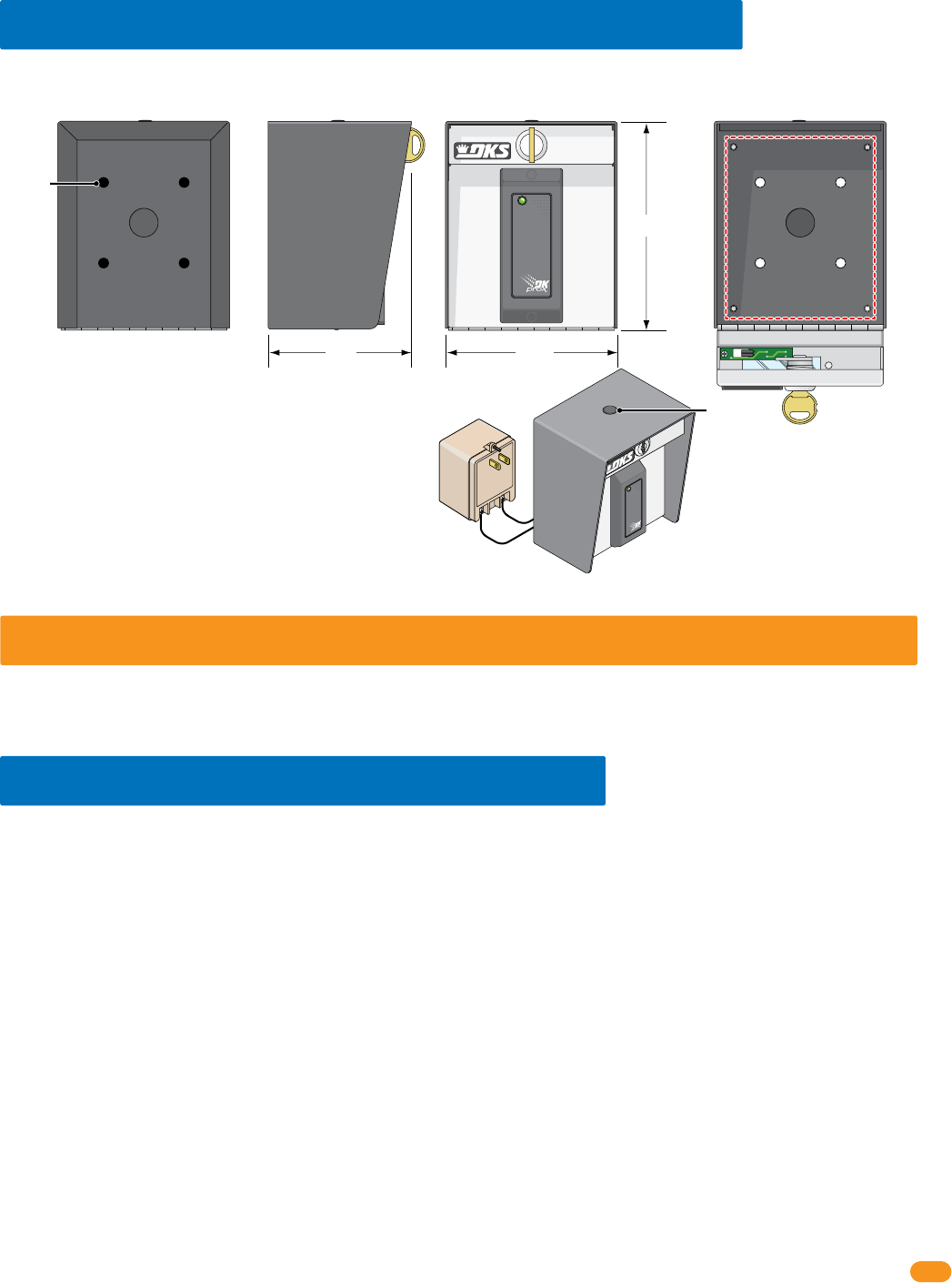
Optional built-in wiegand card reader single enclosure provides a lockable, weather resistant, LED lighted housing for a single tracker
expansion board.
2.4 Single Board Enclosure with Card Reader
Power Supply Note:
The power supply that is
supplied with the enclosure can
also be used to power the tracker
expansion board.
Do Not Connect To A Receptacle
Controlled By A Switch.
Built-In Card Reader with Lighting:
DK Prox Reader - P/N 1815-333
HID Reader - P/N 1815-392
AWID Reader - P/N 1815-292
Mounting Note:
Can be mounted on a DoorKing
gooseneck mounting post.
Tracker
Expansion
Board
Mount
1/2”
Knock-out 6.5”
5.25”4.5”
Mounting
Holes
Optional
Antenna
Mount
Back Side
Card Reader with Lighting
Front Inside Enclosure
2358-065-T-5-18
14
34
33
32
31
30
29
28
27
26
25
24
23
22
21
14
15
16
17
18
19
20
13
12
11
10
9
8
7
6
5
4
3
2
1
ON
1
0
BOARD ADDRESS
0
9
8
7
6
5
4
3
2
1
NC
OUTPUT
RELAY
NO
NC
ALARM
RELAY
NO
NC
AUX
RELAY
NO
ENT
RESET
2358-010
RF
DATA
RF
SECURE
RF
STATUS
CODE
SENT
CODE
GOOD
CODE
BAD
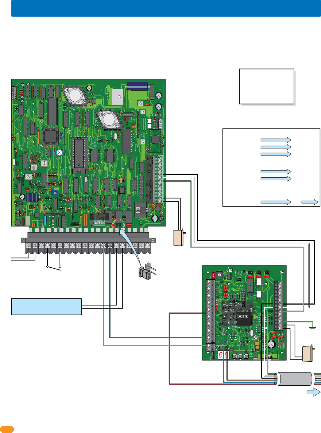
3.2 Board Addresses 3 - 10 Communication Line HARDwiring
NC
NO
RING
ON
CLK
SEN
SPK
VOL
FEED
BACK
RS 232
ELEVATOR
1234 5 67891011121314
1
2
3
MIC
VOL
OFF
KEYPAD
321
321
321
MASTER
CODE
16AC16ACBAT
1NO1NC1C
2RY2C
AZIMC
5VDCIMDSPKRCOMMICPSWCGNDPHONE
12 3 4 201918171615141312111098765
NO NC C
Access Control
System Board
Relay 2
Wiegand 2
Auxiliary Terminal
Main Terminal
Relay 0
Relay 1
Board Address 3
Central Office
phone line -
touch tone,
loop start. Switch closure across
terminals 4 & 6 will
activate relay 1 for its
programmed strike time.
Important Note: Relay 2 is used to
control tracker expansion board
addresses 3-10, Relay 1 or Relay 0 can
be used as the Primary Relay that will
open a visitor door or gate when the
resident pushes “9” on their telephone.
Tracker expansion boards connected to Wiegand 2
will activate Relay 2 in the access control system.
Main Door/Gate
Relay 1 or Relay 0
Auxiliary
Terminal
Black #9-Com
White #8-Data 1
Green #7-Data 0
Black #27
White #28
Green #29
Brown #19
Blue #17
Red #10
Tracker Expansion
Board “Busy” #10
Brown #13
Blue #14
To Board Addresses 4 thru 10
24 tracker expansion boards can be connected to Relay 2/Wiegand 2. If more than 24 tracker expansion boards are desired, see next page.
Note: Terminals
can be removed
from board for
easy wiring.
Ground #32
NO
Com
Ground
12 GA. Wire
Use 6 conductor stranded with overall shield. 18 - 22 gauge.
ONLY use 18 gauge when wiring more than 8 boards.
DO NOT connect shield to 2358-010 board common.
DO NOT use twisted pair.
Communication line to additional boards are
connected in parallel. Allows “teeing” of
communication cable for optimal cable routing.
Aux
Power
Power #33
Power #34
Board Power
16.5 VAC, 20 VA
#10 connects
ONLY to tracker
expansion boards
• Maximum HARDwire run between tracker expansion boards is 4000 ft total, but no more than 2000 ft between any two
boards or from the access control system. See section 2.
• DO NOT use twisted pair wire with wiegand output format.
• Auxiliary terminal power transformer on access control system board must be connected. Otherwise, RS-232, elevator control
and wiegand inputs will not function.
• Proper grounding is required! Ground wire should be a minimum 12 AWG.
Notes:
Board address must be set for EACH BOARD wired, see section 1.6.
13+ Jumper has to be used if more than 12 boards are used, see
section 1.8.
Power, access control devices, door or gate control, aux and alarm
outputs, door and reset switches, request to exit, etc. wiring is not
shown, see section 3.5-3.8.
Gate operator data wiring is not shown, see section 3.10.
Important Wireless Note:
Wireless kits ARE NOT
wired like this. Refer to
wireless instructions with
the wireless kits when using
wireless communication.
Relay 2 Jumper
set to Normally Open
NC
NO
Relay 2/Wiegand 2 to Tracker Expansion
Board Terminal Connection Numbers
Auxiliary Terminal Tracker Terminal
Black #9-Com
White #8-Data 1
Green #7-Data 0
#27
#28
#29
Main Terminal Tracker Terminal
Brown #13-Com
Blue #14-N.O.
#19
#17
Tracker Terminal Tracker Terminal
Red #10-Busy #10
When using multiple tracker boards:
Note: See
section 3.5-3.8
to wire board
options.
2358-065-T-5-18 15
34
33
32
31
30
29
28
27
26
25
24
23
22
21
14
15
16
17
18
19
20
13
12
11
10
9
8
7
6
5
4
3
2
1
ON
1
0
BOARD ADDRESS
0
9
8
7
6
5
4
3
2
1
NC
WIEG TRUE
RELAY
NO
NC
ALARM
RELAY
NO
NC
MONITOR
RELAY
NO
ENT
RESET
2358-010
RF
DATA
RF
SECURE
RF
STATUS
CODE
SENT
CODE
GOOD
CODE
BAD
34
33
32
31
30
29
28
27
26
25
24
23
22
21
14
15
16
17
18
19
20
13
12
11
10
9
8
7
6
5
4
3
2
1
ON
1
0
BOARD ADDRESS
0
9
8
7
6
5
4
3
2
1
NC
WIEG TRUE
RELAY
NO
NC
ALARM
RELAY
NO
NC
MONITOR
RELAY
NO
ENT
RESET
2358-010
RF
DATA
RF
SECURE
RF
STATUS
CODE
SENT
CODE
GOOD
CODE
BAD
NC
NO
RING
ON
CLK
SEN
SPK
VOL
FEED
BACK
RS 232
ELEVATOR
1234 5 67891011121314
1
2
3
MIC
VOL
OFF
KEYPAD
321
321
321
MASTER
CODE
16AC16ACBAT
1NO1NC1C
2RY2CAZIMC
5VDCIMDSPKRCOMMICPSWCGNDPHONE
12 3 4 201918
171615
141312111098765
NO NC C
Access Control
System Board
Relay 1
Relay 2
Auxiliary Terminal
Relay 0
Board Address 11
Board Address 3
Central Office
phone line -
touch tone,
loop start.
Important Note: If both Relay 1 and Relay 2
are used to control tracker expansion
boards, Relay 0 is used as the Primary
Relay that will open a visitor door or gate
when the resident pushes “9” on their
telephone.
Black #27
White #28
Green #29
Ground #32
Auxiliary
Terminal
Black #9
White #8
Green #7
Black #27
White #28
Green #29
Brown #19
Blue #17
Red #10
Brown #19
Brown #15
Blue #17
Red #10
Blue #17
To Board Addresses 4 thru 10
See previous page and next page for additional board wiring.
See next page for additional board wiring.
To Board Addresses 12 thru 18
Up to 24 tracker expansion boards connected to Relay 2/Wiegand 2 THEN connect the next 24 boards to Relay 1/Wiegand 1.
Ground
12 GA. Wire
Ground #32
Ground
Board Power
Switch closure across
terminals 4 & 6 will
activate relay 1 for its
programmed strike time.
Wiegand 1
Wiegand 2
Note: Terminals can be removed
from board for easy wiring.
Notes:
Board address must be set for EACH
BOARD wired, see section 1.6.
13+ Jumper has to be used if more than
12 boards are used, see section 1.8.
Access control devices, door or gate
control, aux and alarm outputs, door
and reset switches, request to exit, etc. wiring is not shown, see section
3.5-3.8.
Gate operator data wiring is not shown, see section 3.10.
Power #33
Power #34 Power #33
Power #34
Board Power
16.5 VAC, 20 VA
Aux
Power
Tracker expansion boards connected to Wiegand 1
will activate Relay 1 in the access control system.
Main Door/Gate
Relay 0
#10 connects
ONLY to
tracker
expansion
boards
#10 connects
ONLY to
tracker
expansion
boards
• Maximum HARDwire run between tracker expansion boards is 4000 ft total, but no more than 2000 ft between any two
boards or from the access control system. See section 2.
• DO NOT use twisted pair wire with wiegand output format.
• Auxiliary terminal power transformer on access conrol system board must be connected. Otherwise, RS-232, elevator control
and wiegand inputs will not function.
• Proper grounding is required! Ground wire should be a minimum 12 AWG.
Auxiliary
Terminal
Black #13-Com
White #12-Data 1
Green #11-Data 0
NO
Com
Tracker Expansion
Board “Busy” #10
Important Wireless Note:
Wireless kits ARE NOT
wired like this. Refer to
wireless instructions with
the wireless kits when using
wireless communication.
3.3 Board Addresses 11 - 18 Communication Line HARDwiring
Set Relay 2 Jumper to Normally Open
Relay 2
Jumper
Use 6 conductor stranded with overall shield. 18 - 22 gauge.
ONLY use 18 gauge when wiring more than 8 boards.
DO NOT connect shield to 2358-010 board common.
DO NOT use twisted pair.
Note: See
section 3.5-3.8
to wire board
options.
2358-065-T-5-18
16
34
33
32
31
30
29
28
27
26
25
24
23
22
21
14
15
16
17
18
19
20
13
12
11
10
9
8
7
6
5
4
3
2
1
2358-010
34
33
32
31
30
29
28
27
26
25
24
23
22
21
14
15
16
17
18
19
20
13
12
11
10
9
8
7
6
5
4
3
2
1
2358-010
34
33
32
31
30
29
28
27
26
25
24
23
22
21
14
15
16
17
18
19
20
13
12
11
10
9
8
7
6
5
4
3
2
1
2358-010
34
33
32
31
30
29
28
27
26
25
24
23
22
21
14
15
16
17
18
19
20
13
12
11
10
9
8
7
6
5
4
3
2
1
2358-010
34
33
32
31
30
29
28
27
26
25
24
23
22
21
14
15
16
17
18
19
20
13
12
11
10
9
8
7
6
5
4
3
2
1
2358-010
34
33
32
31
30
29
28
27
26
25
24
23
22
21
14
15
16
17
18
19
20
13
12
11
10
9
8
7
6
5
4
3
2
1
2358-010
34
33
32
31
30
29
28
27
26
25
24
23
22
21
14
15
16
17
18
19
20
13
12
11
10
9
8
7
6
5
4
3
2
1
2358-010
34
33
32
31
30
29
28
27
26
25
24
23
22
21
14
15
16
17
18
19
20
13
12
11
10
9
8
7
6
5
4
3
2
1
2358-010
34
33
32
31
30
29
28
27
26
25
24
23
22
21
14
15
16
17
18
19
20
13
12
11
10
9
8
7
6
5
4
3
2
1
2358-010
34
33
32
31
30
29
28
27
26
25
24
23
22
21
14
15
16
17
18
19
20
13
12
11
10
9
8
7
6
5
4
3
2
1
2358-010
34
33
32
31
30
29
28
27
26
25
24
23
22
21
14
15
16
17
18
19
20
13
12
11
10
9
8
7
6
5
4
3
2
1
2358-010
34
33
32
31
30
29
28
27
26
25
24
23
22
21
14
15
16
17
18
19
20
13
12
11
10
9
8
7
6
5
4
3
2
1
2358-010
34
33
32
31
30
29
28
27
26
25
24
23
22
21
14
15
16
17
18
19
20
13
12
11
10
9
8
7
6
5
4
3
2
1
2358-010
34
33
32
31
30
29
28
27
26
25
24
23
22
21
14
15
16
17
18
19
20
13
12
11
10
9
8
7
6
5
4
3
2
1
2358-010
34
33
32
31
30
29
28
27
26
25
24
23
22
21
14
15
16
17
18
19
20
13
12
11
10
9
8
7
6
5
4
3
2
1
2358-010
34
33
32
31
30
29
28
27
26
25
24
23
22
21
14
15
16
17
18
19
20
13
12
11
10
9
8
7
6
5
4
3
2
1
2358-010
34
33
32
31
30
29
28
27
26
25
24
23
22
21
14
15
16
17
18
19
20
13
12
11
10
9
8
7
6
5
4
3
2
1
2358-010
34
33
32
31
30
29
28
27
26
25
24
23
22
21
14
15
16
17
18
19
20
13
12
11
10
9
8
7
6
5
4
3
2
1
2358-010
34
33
32
31
30
29
28
27
26
25
24
23
22
21
14
15
16
17
18
19
20
13
12
11
10
9
8
7
6
5
4
3
2
1
2358-010
34
33
32
31
30
29
28
27
26
25
24
23
22
21
14
15
16
17
18
19
20
13
12
11
10
9
8
7
6
5
4
3
2
1
2358-010
34
33
32
31
30
29
28
27
26
25
24
23
22
21
14
15
16
17
18
19
20
13
12
11
10
9
8
7
6
5
4
3
2
1
2358-010
34
33
32
31
30
29
28
27
26
25
24
23
22
21
14
15
16
17
18
19
20
13
12
11
10
9
8
7
6
5
4
3
2
1
2358-010
34
33
32
31
30
29
28
27
26
25
24
23
22
21
14
15
16
17
18
19
20
13
12
11
10
9
8
7
6
5
4
3
2
1
2358-010
34
33
32
31
30
29
28
27
26
25
24
23
22
21
14
15
16
17
18
19
20
13
12
11
10
9
8
7
6
5
4
3
2
1
2358-010
NC
NO
RING
ON
CLK
SEN
ELEVATOR
12345 6 7891011121314
1
2
3
MIC
VOL
OFF
KEYPAD
21
MASTER
CODE
16AC16ACBAT
1NO1NC1C2RY2C
AZIMC
5VDCIMDSPKRCOMMICPSW
D
4201918171615141312111098765
NO NC C
Board Addresses 11 - 18 MUST connect to Relay 1/Wiegand 1 (24 Boards MAX)
Relay 1
Relay 2
Main
Terminal
Auxiliary
Terminal
Access Control System Board
Communication Lines (See section 3.3)
Relay 2
Jumper
Wiegand 1
Black #13-Com
White #12-Data 1
Green #11-Data 0
Wiegand 2
Black #9-Com
White #8-Data 1
Green #7-Data 0
Brown #13 - 2C Common
Blue #14 - 2RY N.O.
Brown #15 - 1C Common
Blue #17 - 1 N.O.
Red #10 - Busy
Relay 2 Jumper
set to Normally Open
3.4 MAX Boards Communication Line HARDwiring
Tracker expansion board addresses 3-10 must be connected to Relay 2/Wiegand 2. Board addresses 11-18 must be connected to Relay 1
/Wiegand 1.
Tracker Expansion Board Notes:
Terminal Connections:
Red #10 - Busy (DO NOT connect to access control system)
Blue #17 - Communication Relay
Brown #19 - Common
Black #27 - Communication Wiegand Common
White #28 - Communication Wiegand Data 1
Green #29 - Communication Wiegand Data 0
• Use 6 conductor stranded with overall shield. 18 - 22
gauge. ONLY use 18 gauge when wiring more than 8
boards, up to 24 boards maximum.
DO NOT connect shield to 2358-010 board common.
DO NOT use twisted pair.
• Board address must be set for EACH BOARD wired,
Zone addresses MUST to be used when wiring more
than 8 boards per relay/wiegand input, but “Zones” can
be used when wiring more than one board to a
relay/wiegand input (See section 1.6). Board addresses
can vary from this illustration.
• Power, access control devices, door or gate control,
alarm outputs, door and reset switches, request to exit,
etc. wiring is not shown, see sections 3.5-3.8.
• 13+ Jumper MUST be used for EACH relay/wiegand wire
run when more than 12 boards are used, see section 1.8.
• Gate operator data wiring is not shown, see section 3.10.
Board Addresses 3 - 10 MUST connect to Relay 2/Wiegand 2 (24 Boards MAX)
Communication Lines (See section 3.2)
Red #10 - Busy
NC
NO
Wiegand 1
Wiegand 2
Board
Address
11
Board
Address
11
Board
Address
11
Board
Address
12
Board
Address
12
Board
Address
12
Board
Address
13
Board
Address
14
Board
Address
3
Board
Address
3
Board
Address
3
Board
Address
4
Board
Address
4
Board
Address
4
Board
Address
5
Board
Address
6
Important Wireless Note:
Wireless kits ARE NOT
wired like this. Refer to
wireless instructions with
the wireless kits when using
wireless communication.
Board
Address
5
Board
Address
5
Board
Address
6
Board
Address
6
34
33
32
31
30
29
28
27
26
25
24
23
22
21
14
15
16
17
18
19
20
13
12
11
10
9
8
7
6
5
4
3
2
1
2358-010
34
33
32
31
30
29
28
27
26
25
24
23
22
21
14
15
16
17
18
19
20
13
12
11
10
9
8
7
6
5
4
3
2
1
2358-010
34
33
32
31
30
29
28
27
26
25
24
23
22
21
14
15
16
17
18
19
20
13
12
11
10
9
8
7
6
5
4
3
2
1
2358-010
34
33
32
31
30
29
28
27
26
25
24
23
22
21
14
15
16
17
18
19
20
13
12
11
10
9
8
7
6
5
4
3
2
1
2358-010
34
33
32
31
30
29
28
27
26
25
24
23
22
21
14
15
16
17
18
19
20
13
12
11
10
9
8
7
6
5
4
3
2
1
2358-010
34
33
32
31
30
29
28
27
26
25
24
23
22
21
14
15
16
17
18
19
20
13
12
11
10
9
8
7
6
5
4
3
2
1
2358-010
34
33
32
31
30
29
28
27
26
25
24
23
22
21
14
15
16
17
18
19
20
13
12
11
10
9
8
7
6
5
4
3
2
1
2358-010
34
33
32
31
30
29
28
27
26
25
24
23
22
21
14
15
16
17
18
19
20
13
12
11
10
9
8
7
6
5
4
3
2
1
2358-010
34
33
32
31
30
29
28
27
26
25
24
23
22
21
14
15
16
17
18
19
20
13
12
11
10
9
8
7
6
5
4
3
2
1
2358-010
34
33
32
31
30
29
28
27
26
25
24
23
22
21
14
15
16
17
18
19
20
13
12
11
10
9
8
7
6
5
4
3
2
1
2358-010
34
33
32
31
30
29
28
27
26
25
24
23
22
21
14
15
16
17
18
19
20
13
12
11
10
9
8
7
6
5
4
3
2
1
2358-010
34
33
32
31
30
29
28
27
26
25
24
23
22
21
14
15
16
17
18
19
20
13
12
11
10
9
8
7
6
5
4
3
2
1
2358-010
Board
Address
10
Board
Address
10
Board
Address
10
Board
Address
9
Board
Address
9
Board
Address
9
Board
Address
8
Board
Address
7
Board
Address
8
Board
Address
8
Board
Address
7
Board
Address
7
Board
Address
13
Board
Address
13
Board
Address
14
Board
Address
14
34
33
32
31
30
29
28
27
26
25
24
23
22
21
14
15
16
17
18
19
20
13
12
11
10
9
8
7
6
5
4
3
2
1
2358-010
34
33
32
31
30
29
28
27
26
25
24
23
22
21
14
15
16
17
18
19
20
13
12
11
10
9
8
7
6
5
4
3
2
1
2358-010
34
33
32
31
30
29
28
27
26
25
24
23
22
21
14
15
16
17
18
19
20
13
12
11
10
9
8
7
6
5
4
3
2
1
2358-010
34
33
32
31
30
29
28
27
26
25
24
23
22
21
14
15
16
17
18
19
20
13
12
11
10
9
8
7
6
5
4
3
2
1
2358-010
34
33
32
31
30
29
28
27
26
25
24
23
22
21
14
15
16
17
18
19
20
13
12
11
10
9
8
7
6
5
4
3
2
1
2358-010
34
33
32
31
30
29
28
27
26
25
24
23
22
21
14
15
16
17
18
19
20
13
12
11
10
9
8
7
6
5
4
3
2
1
2358-010
34
33
32
31
30
29
28
27
26
25
24
23
22
21
14
15
16
17
18
19
20
13
12
11
10
9
8
7
6
5
4
3
2
1
2358-010
34
33
32
31
30
29
28
27
26
25
24
23
22
21
14
15
16
17
18
19
20
13
12
11
10
9
8
7
6
5
4
3
2
1
2358-010
34
33
32
31
30
29
28
27
26
25
24
23
22
21
14
15
16
17
18
19
20
13
12
11
10
9
8
7
6
5
4
3
2
1
2358-010
34
33
32
31
30
29
28
27
26
25
24
23
22
21
14
15
16
17
18
19
20
13
12
11
10
9
8
7
6
5
4
3
2
1
2358-010
34
33
32
31
30
29
28
27
26
25
24
23
22
21
14
15
16
17
18
19
20
13
12
11
10
9
8
7
6
5
4
3
2
1
2358-010
34
33
32
31
30
29
28
27
26
25
24
23
22
21
14
15
16
17
18
19
20
13
12
11
10
9
8
7
6
5
4
3
2
1
2358-010
13+ Jumper
used
13+ Jumper
used
Board
Address
18
Board
Address
18
Board
Address
18
Board
Address
17
Board
Address
17
Board
Address
17
Board
Address
16
Board
Address
15
Board
Address
16
Board
Address
16
Board
Address
15
Board
Address
15
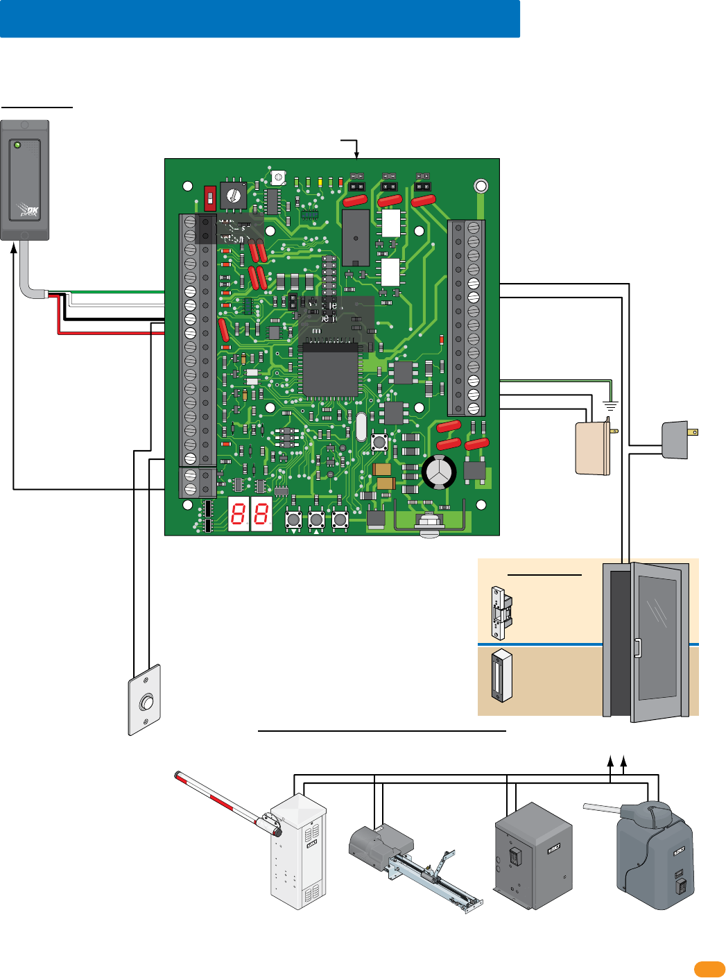
2358-065-T-5-18 17
34
33
32
31
30
29
28
27
26
25
24
23
22
21
14
15
16
17
18
19
20
13
12
11
10
9
8
7
6
5
4
3
2
1
ON
1
0
BOARD ADDRESS
0
9
8
7
6
5
4
3
2
1
NC
OUTPUT
RELAY
NO
NC
ALARM
RELAY
NO
NC
AUX
RELAY
NO
ENT
RESET
2358-010
RF
DATA
RF
SECURE
RF
STATUS
CODE
SENT
CODE
GOOD
CODE
BAD
Request to Exit
Card Reader
Wiegand Access Control Device
Terminals-#25 & #26 Output Relay Jumper
Gate Operator connects
to Terminals-#25 & #26
instead of door.
3.5 Basic Wiring Options at Access Point
Set Output Relay jumper on the tracker expansion board to N.O. (Normally Open) when using fail-secure (electric strike) locking device.
Set Output Relay jumper on the tracker expansion board to N.C. (Normally Closed) when using fail-safe (magnetic lock) locking device.
Set Output Relay jumper on the tracker expansion board to N.O. (Normally Open) when using a gate operator.
Board Address
MUST be set.
See section 1.6.
#6-Green = Data 0
#7-White = Data 1
#8-Black = Common
#9-Red = 12 VDC Power
Door Control
OROR OR
Power for
electric strike or
magnetic lock is
NOT provided
by the system.
Use separate UL
listed power
supply.
Note: Relay contact (25-26) is rated at 1A 30V maximum
and can be set for Normally Open (N.O.) or Normally
Closed (N.C.) operation.
4-6 conductor, stranded with
overall shield, 18-22 gauge.
500 ft max.
DO NOT use twisted pair.
Note: Input - #6, #7, #8, #9
will accept most wiegand
26, 30 and 31-bit access
control devices.
Two wiegand devices can
be connected in parallel to
these terminals if desired.
The access control system
will manage the two
devices connected as if
they were a single
access control device.
Magnetic lock
Output Relay:
Normally Closed (NC)
Electric strike
Output Relay:
Normally Open (NO)
Slide Gate Operator
Output Relay:
Normally Open (NO)
This shows wiring to operate the gate operator ONLY. To wire gate
operator to track and report data to the access control system,
see your specific gate operator data wiring in section 3.10.
Swing Gate Operator
Output Relay:
Normally Open (NO)
Barrier Gate Operator
Output Relay:
Normally Open (NO)
Overhead Gate Operator
Output Relay:
Normally Open (NO)
#8-Common
#20-Card Reader LED or
Beeper Control (Available
on certain card readers)
#18-Request to Exit Input
#25-Output Relay
#26-Output Relay
#33 - 16.5 VAC Power
#32 - Ground Required
#34 - 16.5 VAC Power
Gate Operator Control
Important Note: Communication line
(sections 3.2-3.4) and gate operator data
wiring (section 3.10) is NOT shown.
Board Power
16.5 VAC, 20 VA
Required
18 GA. Wire 100 ft max
16 GA. Wire 200 ft max
Note: Terminals
can be removed
from board for
easy wiring.
EXIT
PUSH TO
Note: If card
reader has
additional
lighting for
outdoor use,
separate power
must be
provided.
Do Not Connect
To A Receptacle
Controlled By A
Switch.
Wire polarity
does not matter.
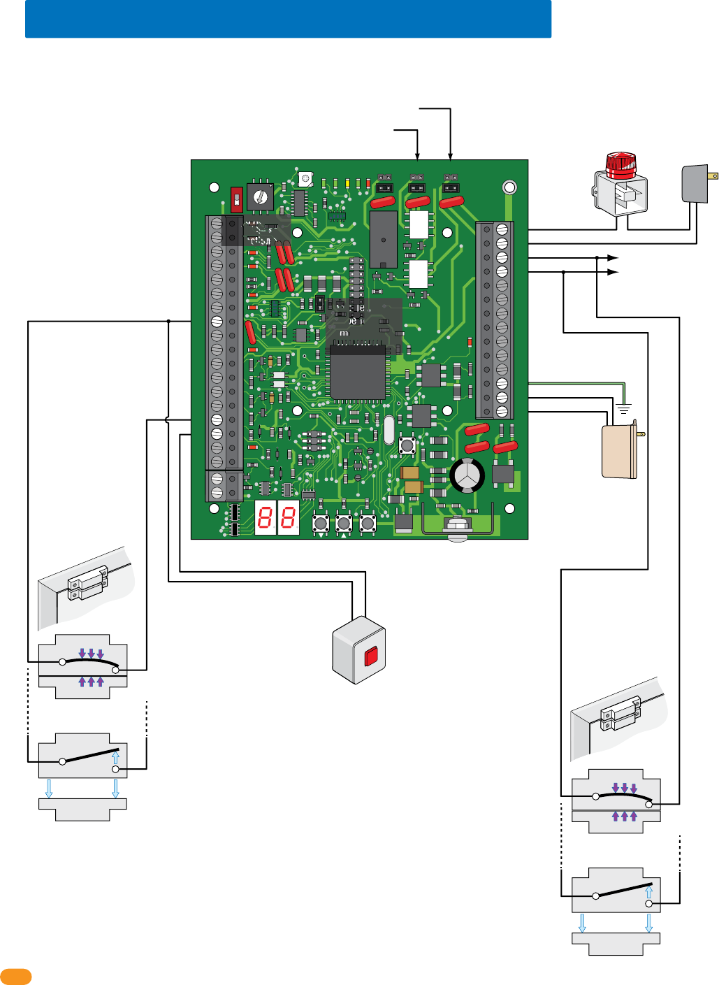
2358-065-T-5-18
18
34
33
32
31
30
29
28
27
26
25
24
23
22
21
14
15
16
17
18
19
20
13
12
11
10
9
8
7
6
5
4
3
2
1
ON
1
0
BOARD ADDRESS
0
9
8
7
6
5
4
3
2
1
NC
OUTPUT
RELAY
NO
NC
ALARM
RELAY
NO
NC
AUX
RELAY
NO
ENT
RESET
2358-010
RF
DATA
RF
SECURE
RF
STATUS
CODE
SENT
CODE
GOOD
CODE
BAD
Local
Alarm
Separate
Alarm
Power
External Alarm Reset
Door Contact Switch
Integral Mode
(Programming Step 16)
Dry relay contacts connect
to existing alarm system.
Terminals-#23 & #24 Alarm Relay Jumper
Terminals-#21 & #22 Aux Relay Jumper
3.6 Alarm Wiring Options at Access Point
Board Address
MUST be set.
See section 1.6.
Note: Relay contacts (21-22; 23-24) are rated at 1A 30V
maximum and can be set for Normally Open (N.O.) or
Normally Closed (N.C.) operation.
Set Alarm Relay
jumper typically (NO).
Set Auxiliary Relay jumper typically (NO).
#8-Common
#8-Common
#21-Auxiliary Relay
#23-Alarm Relay
#24-Alarm Relay
#33 - 16.5 VAC Power
#32 - Ground Required
#34 - 16.5 VAC Power
#22-Auxiliary Relay
#16-Reset Alarm Input
#15-Door Ajar Input
Important Note: Communication line
(sections 3.2-3.4) is NOT shown.
Board Power
16.5 VAC, 20 VA
Required
18 GA. Wire 100 ft max
16 GA. Wire 200 ft max
Note: Terminals
can be removed
from board for
easy wiring.
Door
Door Frame
Door Contact Switch
Bypass Mode
(Programming Step 16)
MUST be connected to
existing alarm system.
#23-Alarm Relay
#24-Alarm Relay
Door
Door Frame
Switch Closed:
Door Closed
N.C.
Com
Switch Open:
Door Open
N.C.
Magnet
SPST (NO)
SPST (NO)
Com
Switch Closed:
Door Closed
N.C.
Com
Switch Open:
Door Open
N.C.
Magnet
SPST (NO)
SPST (NO)
Com
Note: Input for door contact switch is factory set at
0 for normally Open (Circuit Open - CO) but it can
be set for normally Closed (Circuit Closed - CC) by
programming step 8, set to 1 if required.
PRESS
to RESET
Do Not Connect
To A Receptacle
Controlled By A
Switch.
Wire polarity
does not matter.
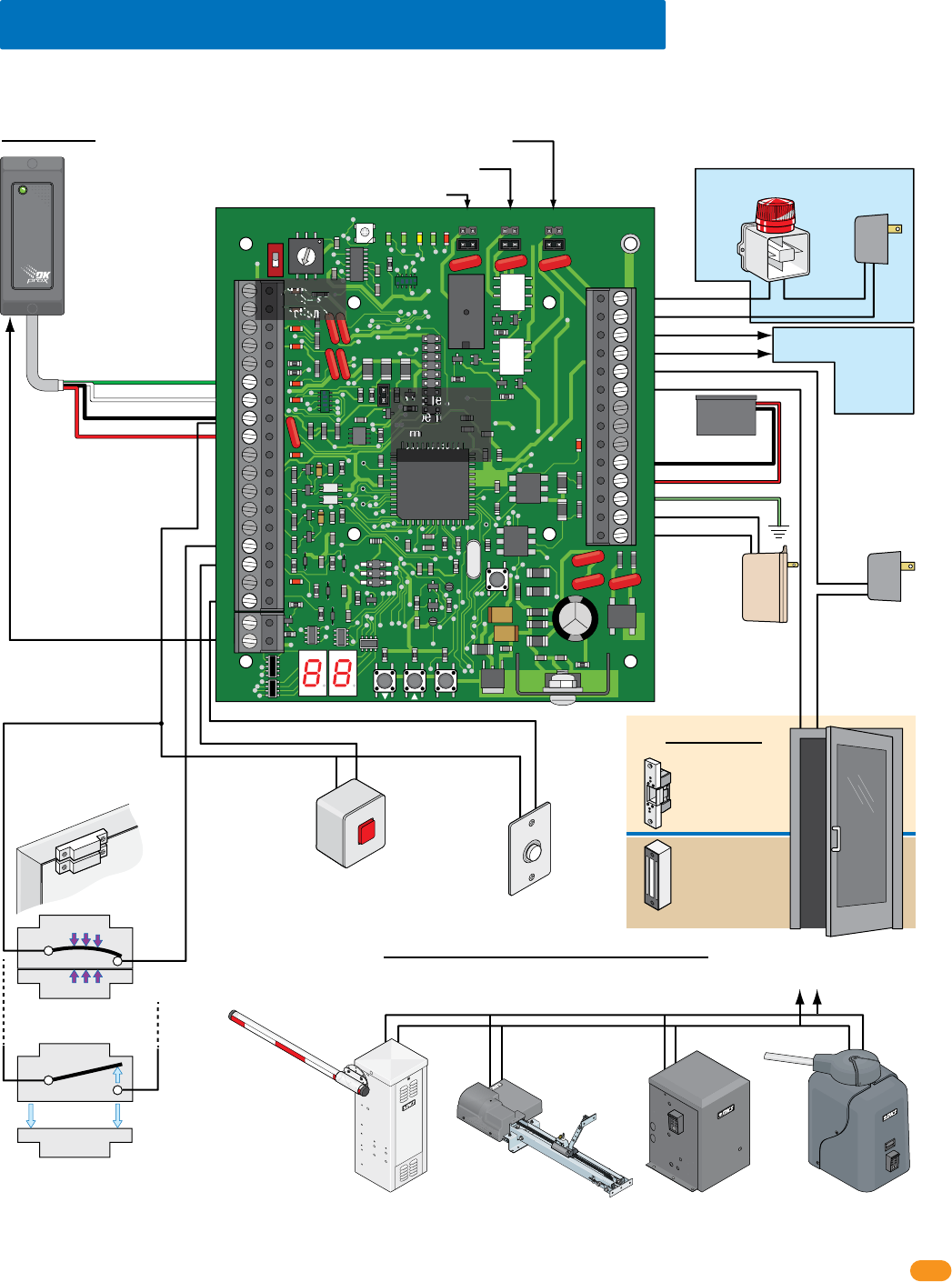
2358-065-T-5-18 19
Switch Closed:
Door Closed
N.C.
Com
Switch Open:
Door Open
N.C.
Magnet
SPST (NO)
SPST (NO)
Com
34
33
32
31
30
29
28
27
26
25
24
23
22
21
14
15
16
17
18
19
20
13
12
11
10
9
8
7
6
5
4
3
2
1
ON
1
0
BOARD ADDRESS
0
9
8
7
6
5
4
3
2
1
NC
OUTPUT
RELAY
NO
NC
ALARM
RELAY
NO
NC
AUX
RELAY
NO
ENT
RESET
2358-010
RF
DATA
RF
SECURE
RF
STATUS
CODE
SENT
CODE
GOOD
CODE
BAD
Local
Alarm
Separate
Alarm
Power
External Alarm Reset
Request to Exit
Card Reader
Wiegand Access Control Device
Dry relay contacts connect
to existing alarm system.
Terminals-#25 & #26 Output Relay Jumper
Terminals-#23 & #24 Alarm Relay Jumper
Terminals-#21 & #22 Aux Relay Jumper
Gate Operator connects
to Terminals-#25 & #26
instead of door.
3.7 All Available Devices at Access Point
Set Output Relay jumper on the tracker expansion board to N.O. (Normally Open) when using fail-secure (electric strike) locking device.
Set Output Relay jumper on the tracker expansion board to N.C. (Normally Closed) when using fail-safe (magnetic lock) locking device.
Set Output Relay jumper on the tracker expansion board to N.O. (Normally Open) when using a gate operator.
Board Address
MUST be set.
See section 1.6.
#6-Green = Data 0
#7-White = Data 1
#8-Black = Common
#9-Red = 12 VDC Power
Door Control
OROR OR
Power for electric
strike or magnetic
lock is NOT
provided by the
system. Use
separate UL listed
power supply.
Note: Relay contacts (21-22; 23-24; 25-26) are rated at 1A
30V maximum and can be set for Normally Open (N.O.) or
Normally Closed (N.C.) operation.
4-6 conductor, stranded with
overall shield, 18-22 gauge.
500 ft max.
DO NOT use twisted pair.
Set Alarm
Relay jumper
typically (NO).
Set Auxiliary Relay
jumper typically (NO).
Magnetic lock
Output Relay:
Normally Closed (NC)
Electric strike
Output Relay:
Normally Open (NO)
Slide Gate Operator
Output Relay:
Normally Open (NO)
This shows wiring to operate the gate operator ONLY. To wire gate
operator to track and report data to the access control system,
see your specific gate operator data wiring in section 3.10.
Swing Gate Operator
Output Relay:
Normally Open (NO)
Barrier Gate Operator
Output Relay:
Normally Open (NO)
Overhead Gate Operator
Output Relay:
Normally Open (NO)
#8-Common
#8-Common
#20-Card Reader LED or
Beeper Control (Available
on certain card readers)
#18-Request to Exit Input
#21-Auxiliary Relay
#23-Alarm Relay
#24-Alarm Relay
#25-Output Relay
#26-Output Relay
#33 - 16.5 VAC Power
#32 - Ground Required
#31 - Battery Back-Up (+)
#30 - Battery Back-Up (-)
#34 - 16.5 VAC Power
#22-Auxiliary Relay
#16-Reset Alarm Input
#15-Door Ajar Input
Gate Operator Control
Important Note: Communication line
(sections 3.2-3.4) and gate operator data
wiring (section 3.10) is NOT shown.
Board Power
16.5 VAC, 20 VA
Required
18 GA. Wire 100 ft max
16 GA. Wire 200 ft max
Note: Terminals
can be removed
from board for
easy wiring.
1 Board:
.8 Amp/Hour
Battery
Optional
EXIT
PUSH TO
Door
Door Frame
Door Contact Switch
Integral Mode shown
(See previous page)
Note: Input - #6, #7, #8, #9
will accept most wiegand
26, 30 and 31-bit access
control devices.
Two wiegand devices can
be connected in parallel to
these terminals if desired.
The access control system
will manage the two
devices connected as if
they were a single
access control device.
Note: If card
reader has
additional
lighting for
outdoor use,
separate power
must be
provided.
PRESS
to RESET
Do Not Connect
To A Receptacle
Controlled By A
Switch.
Wire polarity
does not matter.
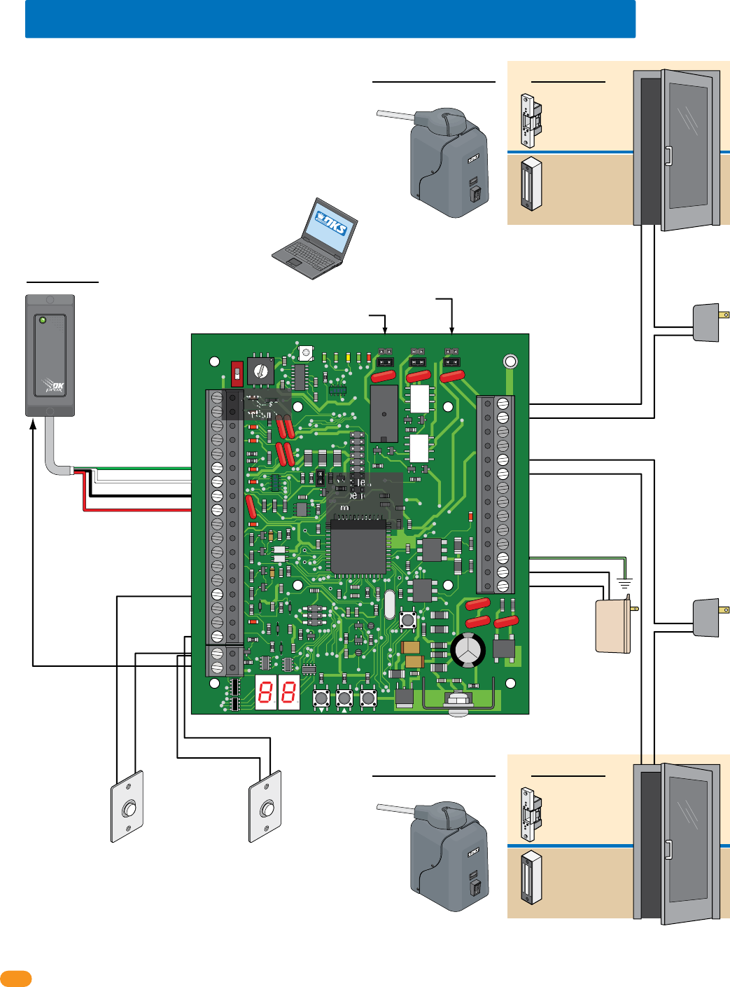
2358-065-T-5-18
20
34
33
32
31
30
29
28
27
26
25
24
23
22
21
14
15
16
17
18
19
20
13
12
11
10
9
8
7
6
5
4
3
2
1
ON
1
0
BOARD ADDRESS
0
9
8
7
6
5
4
3
2
1
NC
OUTPUT
RELAY
NO
NC
ALARM
RELAY
NO
NC
AUX
RELAY
NO
ENT
RESET
2358-010
RF
DATA
RF
SECURE
RF
STATUS
CODE
SENT
CODE
GOOD
CODE
BAD
Request to Exit
Card Reader
Wiegand Access Control Device
Terminals-#25 & #26 Output Relay Jumper
3.8 Typical Dual Mode Wiring at 2 Access Points
Board Address
MUST be set.
See section 1.6.
Terminals-#21 & #22 Aux Relay Jumper
#6-Green = Data 0
#7-White = Data 1
#8-Black = Common
#9-Red = 12 VDC Power
Door Control
Access Point 1Access Point 2
OR
Power for electric
strike or magnetic
lock is NOT
provided by the
system. Use
separate UL listed
power supply.
4-6 conductor, stranded with
overall shield, 18-22 gauge.
500 ft max.
DO NOT use twisted pair.
Magnetic lock
Output Relay:
Normally Closed (NC)
Electric strike
Output Relay:
Normally Open (NO)
Gate Operator
Output Relay:
Normally Open (NO).
Gate Operator connects
to Terminals-#25 & #26
instead of door.
Request to Exit Note:
No alarm functions
No door ajar functions
Power for electric
strike or magnetic
lock is NOT
provided by the
system. Use
separate UL listed
power supply.
#19-Common
#18-Request to Exit Input
#19-Common
#15-Request to Exit Input
for second Door
#25-Output Relay
#26-Output Relay
#21-Aux Relay
#22-Aux Relay
#33 - 16.5 VAC Power
#32 - Ground Required
#34 - 16.5 VAC Power
Gate Operator Control
Door Control
OR
Magnetic lock
Output Relay:
Normally Closed (NC)
Electric strike
Output Relay:
Normally Open (NO)
Gate Operator
Output Relay:
Normally Open (NO).
Gate Operator connects
to Terminals-#21 & #22
instead of door.
Gate Operator Control
Access Point 2
Board Address Setting Plus 1
in DKS Remote Account Manager Software
Access Point 1
Board Address Setting in DKS Remote Account Manager Software
Important Note: Communication line
(sections 3.2-3.4) and gate operator data
wiring (section 3.10) is NOT shown.
Board Power
16.5 VAC, 20 VA
Required
18 GA. Wire 100 ft max
16 GA. Wire 200 ft max
Note: Terminals
can be removed
from board for
easy wiring.
#20-Card
Reader LED or
Beeper Control
(Available
on certain card
readers)
Request to Exit
EXIT
PUSH TO
EXIT
PUSH TO
One tracker expansion board can be programmed
(step 12, set to 1) to control 2 access points. The board
address number that has been physically set on the
tracker expansion board and the NEXT sequential board
address number will control the 2 access points. When
the access device (Card Reader) gets activated from
Access point 1 and access is granted or denied, the
board will then automatically send out the same access
device information to the next sequential board address
number (Access Point 2) to grant or deny access to the
second access point. The system relays will be
identified in DKS Remote Account Manager software as
the board address setting for Access Point 1 and board
address setting plus 1 for Access point 2.
SOFTWARE
INSTALLED
Note: Input - #6, #7, #8, #9 will
accept most wiegand 26, 30 and
31-bit access control devices.
Two wiegand devices can be
connected in parallel to these
terminals if desired. The access
control system will
manage the two
devices connected
as if they were a
single access
control device.
Note: If card
reader has
additional
lighting for
outdoor use,
separate power
must be
provided.
Do Not Connect
To A Receptacle
Controlled By A
Switch.
Wire polarity
does not matter.
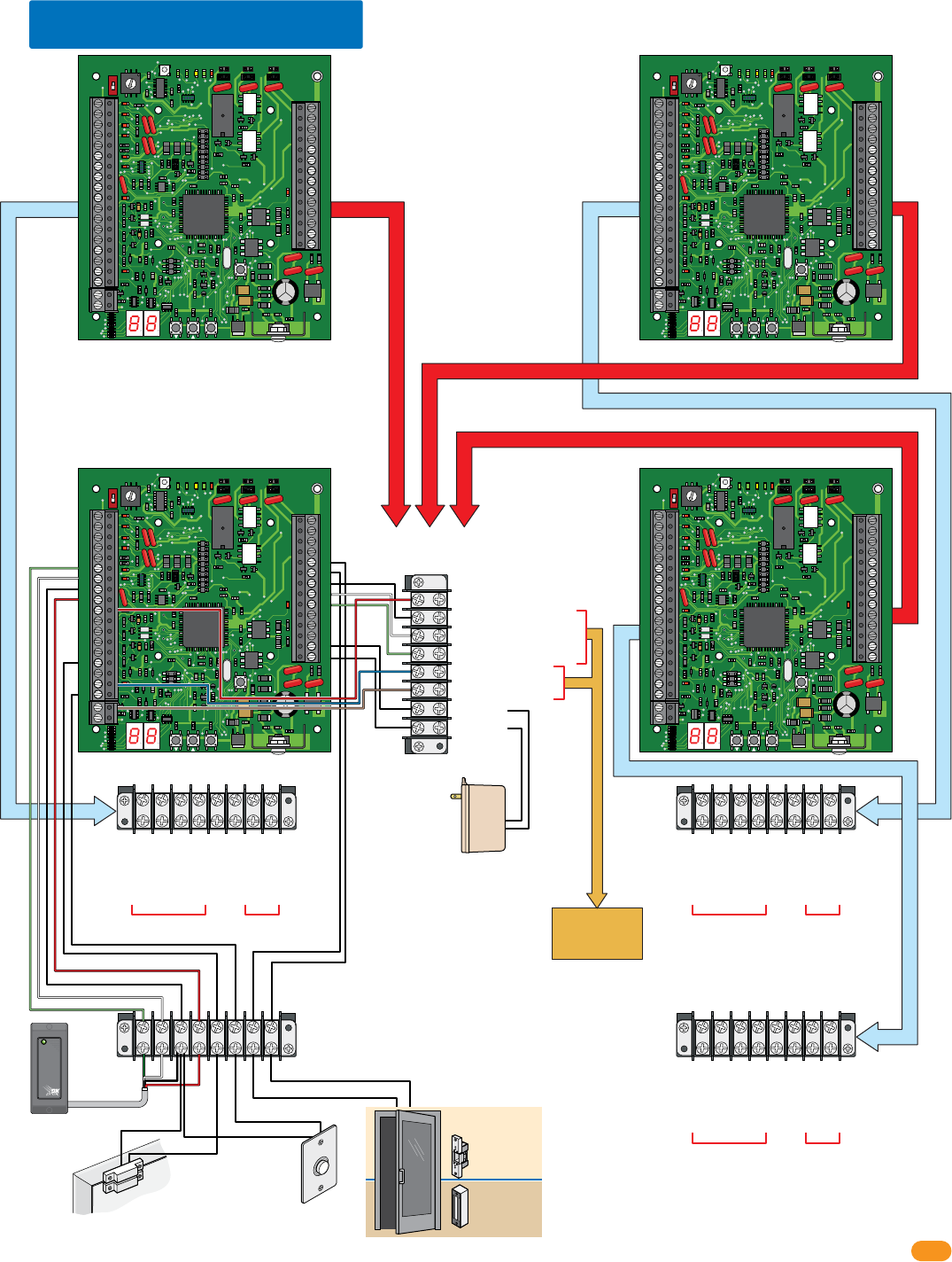
2358-065-T-5-18 21
34
33
32
31
30
29
28
27
26
25
24
23
22
21
14
15
16
17
18
19
20
13
12
11
10
9
8
7
6
5
4
3
2
1
ON
1
0
BOARD ADDRESS
0
9
8
7
6
5
4
3
2
1
NC
OUTPUT
RELAY
NO
NC
ALARM
RELAY
NO
NC
AUX
RELAY
NO
ENT
RESET
2358-010
RF
DATA
RF
SECURE
RF
STATUS
CODE
SENT
CODE
GOOD
CODE
BAD
34
33
32
31
30
29
28
27
26
25
24
23
22
21
14
15
16
17
18
19
20
13
12
11
10
9
8
7
6
5
4
3
2
1
ON
1
0
BOARD ADDRESS
0
9
8
7
6
5
4
3
2
1
NC
OUTPUT
RELAY
NO
NC
ALARM
RELAY
NO
NC
AUX
RELAY
NO
ENT
RESET
2358-010
RF
DATA
RF
SECURE
RF
STATUS
CODE
SENT
CODE
GOOD
CODE
BAD
34
33
32
31
30
29
28
27
26
25
24
23
22
21
14
15
16
17
18
19
20
13
12
11
10
9
8
7
6
5
4
3
2
1
ON
1
0
BOARD ADDRESS
0
9
8
7
6
5
4
3
2
1
NC
OUTPUT
RELAY
NO
NC
ALARM
RELAY
NO
NC
AUX
RELAY
NO
ENT
RESET
2358-010
RF
DATA
RF
SECURE
RF
STAT US
CODE
SENT
CODE
GOOD
CODE
BAD
34
33
32
31
30
29
28
27
26
25
24
23
22
21
14
15
16
17
18
19
20
13
12
11
10
9
8
7
6
5
4
3
2
1
ON
1
0
BOARD ADDRESS
0
9
8
7
6
5
4
3
2
1
NC
OUTPUT
RELAY
NO
NC
ALARM
RELAY
NO
NC
AUX
RELAY
NO
ENT
RESET
2358-010
RF
DATA
RF
SECURE
RF
STAT US
CODE
SENT
CODE
GOOD
CODE
BAD
3.9 Quad Box Wiring
4 Boards Power
16.5 VAC, 50 VA Required
18 GA. Wire 100 ft max
16 GA. Wire 200 ft max
Communication
Lines and Power
Terminal
Access Point
Board Terminal
Access Point Board Terminal
To DoorKing
Access Control
System
Access
Point
Board
Terminal
Access
Point
Board
Terminal
#6-Green
#7-White
#8-Black
#9-Red
#10-Red Busy
#27-Black Communication Com
#28-White Communication Data 1
#29-Green Communication Data 0
#17-Blue Relay Input NO
#19-Brown Relay Input Com
#33-16.5 VAC
#34-16.5 VAC
#6-Green Data 0
#7-White Data 1
#8-Black Common
#9-Red 12 VDC
#15-Door Ajar Input
#18-Request to Exit
#26-Output Relay
#25-Output Relay
From
Card Reader
Card Reader
Request to Exit
Button
From
Door Lock
#6-Green Data 0
#7-White Data 1
#8-Black Common
#9-Red 12 VDC
#15-Door Ajar Input
#18-Request to Exit
#26-Output Relay
#25-Output Relay
From
Card Reader
From
Door Lock
#6-Green Data 0
#7-White Data 1
#8-Black Common
#9-Red 12 VDC
#15-Door Ajar Input
#18-Request to Exit
#26-Output Relay
#25-Output Relay
From
Card Reader
From
Door Lock
Sample Board Wiring
Each of the boards are wired to their own
Access Point Board Terminal and all are wired to
the Communication Lines and Power Terminal.
DO NOT wire to access control system
Important Note: Gate
operator data wiring
(section 3.10) is NOT
shown.
Important Note: 115 VAC
convience outlets power
wiring for quad box (section
2.3) is NOT shown.
Magnetic Contact Switch Door Ajar Input
#15-Door
Ajar Input
#18-Request to Exit
#25-Output Relay
#26-Output Relay
#8-Common #8-Common
EXIT
PUSH TO
Red
Green
Black
White
Magnetic lock
Output Relay:
Normally Closed (NC)
Electric strike
Output Relay:
Normally Open (NO)
Door Lock
Do Not Connect
To A Receptacle
Controlled By A
Switch.
Wire polarity
does not matter.
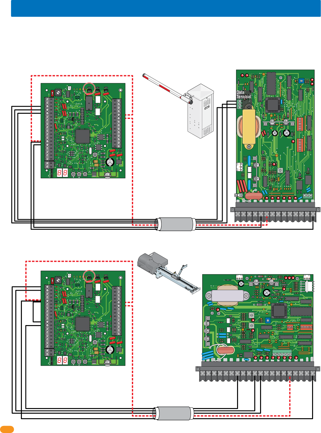
2358-065-T-5-18
22
Output Relay Jumper “NO”
34
33
32
31
30
29
28
27
26
25
24
23
22
21
14
15
16
17
18
19
20
13
12
11
10
9
8
7
6
5
4
3
2
1
ON
1
0
BOARD ADDRESS
0
9
8
7
6
5
4
3
2
1
NC
OUTPUT
RELAY
NO
NC
ALARM
RELAY
NO
NC
AUX
RELAY
NO
ENT
RESET
2358-010
RF
DATA
RF
SECURE
RF
STATUS
CODE
SENT
CODE
GOOD
CODE
BAD
LIMIT
LIMIT
PA R T
TIME
DELAY
REV SENSE
CLOSE
REV SENSE
OPEN
1
ON
2 3 41
ON
2 3 4 5 6 7 8
NO NC
EXIT
LOOP
REVERSE
LOOP
GATE FORCED
20 19 18 17 16 15 14 13 12 11 10 987654321
4402-010
3.10 Gate Operator Data Wiring - Optional Control Wiring
Each tracker expansion board can report data about gate operators SPECIFIC activity to the access control system. Two (2) DoorKing gate
operators; a slide, swing or overhead gate operator and a barrier gate operator can be “Tracked”. See section 5.3 for a list of the events that
can be reported (Tracked). The gate operators can also be controlled (Opened and closed) if desired by wiring the red dashed wires along with
the black wires in the diagrams. Choose your specific gate operator model from the 6 diagrams shown on the next 3 pages. Only DoorKing
gate operators shown in the 6 diagrams will function. DO NOT wire the tracker expansion board to a third party gate operator.
REVERSE
SENSITIVITY
TIME
DELAY
POWER
1
ON
2 3 4 5 6 7 81
ON
2 3 4 5 6 7 8
NC NO
UP
LOOP
DOWN
LOOP
1234567 8 9 10 11 12 13 14
1601-010
Output Relay Jumper “NO”
34
33
32
31
30
29
28
27
26
25
24
23
22
21
14
15
16
17
18
19
20
13
12
11
10
9
8
7
6
5
4
3
2
1
ON
1
0
BOARD ADDRESS
0
9
8
7
6
5
4
3
2
1
NC
OUTPUT
RELAY
NO
NC
ALARM
RELAY
NO
NC
AUX
RELAY
NO
ENT
RESET
2358-010
RF
DATA
RF
SECURE
RF
STATUS
CODE
SENT
CODE
GOOD
CODE
BAD
Data
Terminal
3 - Data
2 - Busy
1 - Com
1601, 1602, 1603 Barrier Gate Operators
1150 Overhead Gate Operator
25
26
25
26
3From 3 Data
From 2 Busy
From 1 Com
4
5
13
13
14
12
1
2
5
5
Jumper 5-11
Use 6 conductor,
stranded with overall
shield. 18-22 gauge.
DO NOT use twisted
pair.
Use 6 conductor,
stranded with overall
shield. 18-22 gauge.
DO NOT use twisted
pair.
Dashed lines are ONLY
required if the tracker
expansion board is to
OPEN the vehicular
overhead gate when a
valid access code has
been received (Output
relay jumper is set to
normally open).
Dashed lines are ONLY
required if the tracker
expansion board is to
RAISE the barrier arm
when a valid access
code has been
received (Output relay
jumper is set to
normally open).
Black lines are for gate operator data wiring ONLY.
Black lines are for gate operator data wiring ONLY.
3 to Data Term 3
4 to Data Term 2
5 to Data Term 1
13 to 14
14 to 5
1 to 10
2 to 11
5 to 1
12 to 14
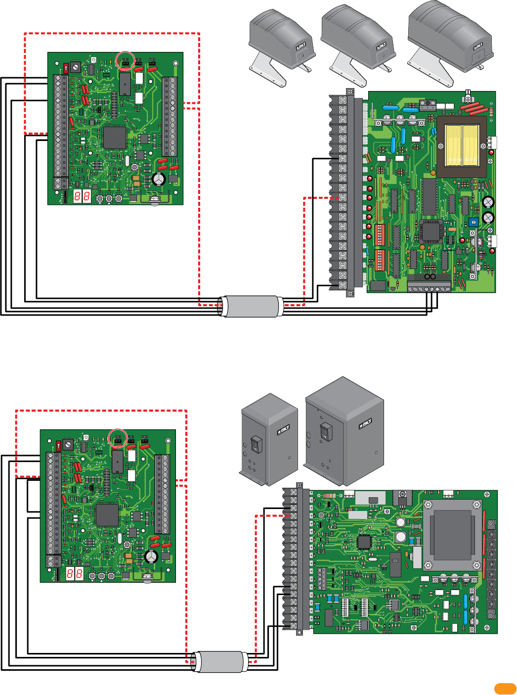
2358-065-T-5-18 23
Output Relay Jumper “NO”
34
33
32
31
30
29
28
27
26
25
24
23
22
21
14
15
16
17
18
19
20
13
12
11
10
9
8
7
6
5
4
3
2
1
ON
1
0
BOARD ADDRESS
0
9
8
7
6
5
4
3
2
1
NC
OUTPUT
RELAY
NO
NC
ALARM
RELAY
NO
NC
AUX
RELAY
NO
ENT
RESET
2358-010
RF
DATA
RF
SECURE
RF
STATUS
CODE
SENT
CODE
GOOD
CODE
BAD
Output Relay Jumper “NO”
34
33
32
31
30
29
28
27
26
25
24
23
22
21
14
15
16
17
18
19
20
13
12
11
10
9
8
7
6
5
4
3
2
1
ON
1
0
BOARD ADDRESS
0
9
8
7
6
5
4
3
2
1
NC
OUTPUT
RELAY
NO
NC
ALARM
RELAY
NO
NC
AUX
RELAY
NO
ENT
RESET
2358-010
RF
DATA
RF
SECURE
RF
STATUS
CODE
SENT
CODE
GOOD
CODE
BAD
ON
ON
REVERSE
SENSITIVITY
REVERSE
LOOP
EXIT
LOOP
KEY SWITCH
4602-010
SW1 SW2
OPEN
TIMER
NC
1
2
3
4
5
NO
18
17
16
15
14
13
12
11
10
9
8
7
6
5
4
3
2
1
20
19
18
17
16
15
14
13
12
11
10
9
8
7
6
5
4
3
2
1
NC
NO
1
ON
2 3 4 5 6 7 81
ON
2 3 4 5 6 7 8
123456 87
Auxiliary Terminal
4502-010
6050, 6100, 6300 Swing Gate Operators
9100, 9150 Slide Gate Operators
25
26
11
11
1
2
5
12
12
25
26
1
2
5
5
Jumper 5-11
Use 6 conductor,
stranded with overall
shield. 18-22 gauge.
DO NOT use twisted
pair.
Dashed lines are ONLY
required if the tracker
expansion board is to
OPEN the vehicular
gate when a valid
access code has been
received (Output relay
jumper is set to
normally open).
Use 6 conductor,
stranded with overall
shield. 18-22 gauge.
DO NOT use twisted
pair.
Dashed lines are ONLY
required if the tracker
expansion board is to
OPEN the vehicular
gate when a valid
access code has been
received (Output relay
jumper is set to
normally open).
Black lines are for gate operator data wiring ONLY.
Black lines are for gate operator data wiring ONLY.
1 to 14
2 to 13
5 to 18
12 to 3
1 to Aux 4
2 to Aux 5
5 to Aux 6
11 to 20
12 to 7
6050
6100
6300
9100
9150
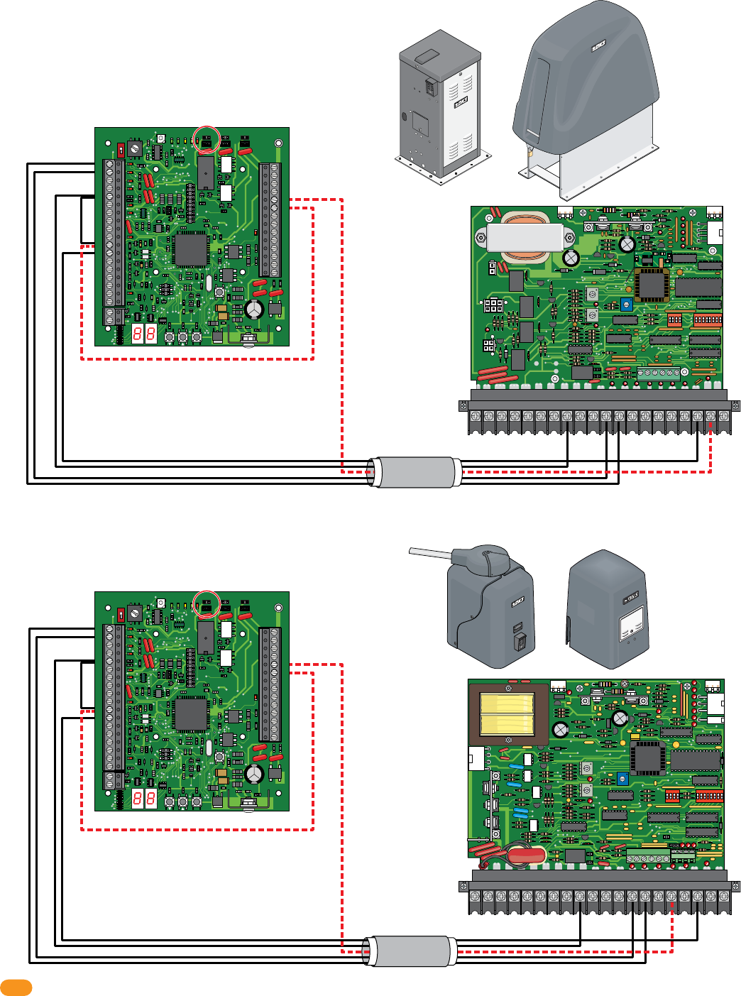
2358-065-T-5-18
24
Output Relay Jumper “NO”
34
33
32
31
30
29
28
27
26
25
24
23
22
21
14
15
16
17
18
19
20
13
12
11
10
9
8
7
6
5
4
3
2
1
ON
1
0
BOARD ADDRESS
0
9
8
7
6
5
4
3
2
1
NC
OUTPUT
RELAY
NO
NC
ALARM
RELAY
NO
NC
AUX
RELAY
NO
ENT
RESET
2358-010
RF
DATA
RF
SECURE
RF
STATUS
CODE
SENT
CODE
GOOD
CODE
BAD
Output Relay Jumper “NO”
34
33
32
31
30
29
28
27
26
25
24
23
22
21
14
15
16
17
18
19
20
13
12
11
10
9
8
7
6
5
4
3
2
1
ON
1
0
BOARD ADDRESS
0
9
8
7
6
5
4
3
2
1
NC
OUTPUT
RELAY
NO
NC
ALARM
RELAY
NO
NC
AUX
RELAY
NO
ENT
RESET
2358-010
RF
DATA
RF
SECURE
RF
STATUS
CODE
SENT
CODE
GOOD
CODE
BAD
Use 6 conductor,
stranded with overall
shield. 18-22 gauge.
DO NOT use twisted
pair.
Use 6 conductor,
stranded with overall
shield. 18-22 gauge.
DO NOT use twisted
pair.
4404-010
TIME
DELAY
EXIT
LOOP
LMT
LMT
REVERSE
LOOP
REV SENSE
OPEN
REV SENSE
CLOSE
1
ON
2 3 41
ON
2 3 4 5 6 7 8
NC
NO
P8 P7P6
20 19 18 17 16 15 14 13 12 11 10 9 87654321
4404-010
9200 Series, 9500 Slide Gate Operators
25
26
11
1
2
5
12
Jumper 5-11
1
ON SW 1
2 3 4 1
ON SW 2
REVERSE
LOOP
P2 P8
EXIT
LOOP
SELF
TEST
NC
TIME
DELAY
NO
REV SENSE
PRIMARY
REV SENSE
SECONDARY
1
2
3
4
5
6
7
8
9
13
12
11
10
14
15
16
17
18
19
20
2 3 45 6 7 8
4405-010
20 19 18 17 16 15 14 13 12 11 10 987654321
6500 Series Swing Gate Operators, 9000 Slide Gate Operators
25
26
11
1
2
5
12
Jumper 5-11
Dashed lines are ONLY
required if the tracker
expansion board is to
OPEN the vehicular
gate when a valid
access code has been
received (Output relay
jumper is set to
normally open).
Dashed lines are ONLY
required if the tracker
expansion board is to
OPEN the vehicular
gate when a valid
access code has been
received (Output relay
jumper is set to
normally open).
Black lines are for gate operator data wiring ONLY.
Black lines are for gate operator data wiring ONLY.
1 to 9
2 to 10
5 to 13
12 to 3
1 to 7
2 to 8
5 to 12
12 to 3
9000
6500
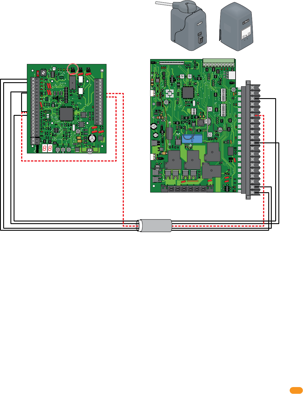
2358-065-T-5-18 25
12345678
ON
12345678
ON
20
19
18
17
16
15
14
13
12
11
10
9
8
7
6
5
4
3
2
1
EXIT
LOOP
REVERSE
LOOP
POWER SEL
AC POWER/SOLAR
REV SENSE
P3
SELF TEST
RESET
RED=CHARGING
GREEN=CHARGED
KEY
SWITCH
NO
NC
3 BUTTON
CONTROL
SW1
SW2
OFF ON
POWER
P4
P2
16
TIME DELAY
4100-010
12345678910
1234
ON
OPEN BEAM
CLOSE BEAM
OPEN EDGE
CLOSE EDGE
Output Relay Jumper “NO”
34
33
32
31
30
29
28
27
26
25
24
23
22
21
14
15
16
17
18
19
20
13
12
11
10
9
8
7
6
5
4
3
2
1
ON
1
0
BOARD ADDRESS
0
9
8
7
6
5
4
3
2
1
NC
OUTPUT
RELAY
NO
NC
ALARM
RELAY
NO
NC
AUX
RELAY
NO
ENT
RESET
2358-010
RF
DATA
RF
SECURE
RF
STATUS
CODE
SENT
CODE
GOOD
CODE
BAD
Use 6 conductor,
stranded with overall
shield. 18-22 gauge.
DO NOT use twisted pair.
25
26
11
1
2
5
12
Jumper 5-11
Dashed lines are ONLY
required if the tracker
expansion board is to
OPEN the vehicular
gate when a valid
access code has been
received (Output relay
jumper is set to
normally open).
Black lines are for gate operator data wiring ONLY.
1 to 20
2 to 19
5 to 11
12 to 3
AC Powered 6524 Swing / 9024 Slide Gate Operators ONLY
AC Powered ONLY
Not for use with the SOLAR Powered 6524 or 9024.
9024
6524
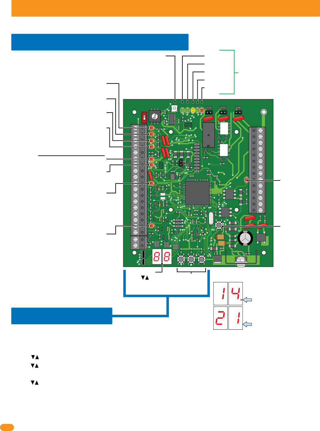
2358-065-T-5-18
26
34
33
32
31
30
29
28
27
26
25
24
23
22
21
14
15
16
17
18
19
20
13
12
11
10
9
8
7
6
5
4
3
2
1
ON
1
0
BOARD ADDRESS
0
9
8
7
6
5
4
3
2
1
NC
OUTPUT
RELAY
NO
NC
ALARM
RELAY
NO
NC
AUX
RELAY
NO
ENT
RESET
2358-010
RF
DATA
RF
SECURE
RF
STATUS
CODE
SENT
CODE
GOOD
CODE
BAD
SECTION 4 - PROGRAMMING
Before beginning any programming, the tracker expansion board MUST be completely wired and the board MUST have power.
4.1 LED and Button Descriptions
RF DATA
RF STATUS
CODE SENT
CODE GOOD
CODE BAD
RESET Button
Resets board after
adjustments have
been made.
RF SECURE -
BAD
BAD
BA
BA
GOOD
GOO
GOO
OO
SENT
SENT
SEN
EN
TATU
TATU
ATU
ATU
DATA
DATA
ATA
AT
Gate Operator 1 Data Input -
Blinks red when operator data is sent.
Gate Operator 1 Data Output -
Blinks red when operator data is received.
Gate Operator 2 Data Input -
Blinks red when operator data is sent.
Gate Operator 2 Data Output -
Blinks red when operator data is received.
Wiegand Data 0 - Blinks red when
wiegand data is sent.
Wiegand Data 1 - Blinks red when
wiegand data is sent.
LED Display
Wiegand Output -
Blinks red when
wiegand data is
sent.
LED DOES NOT
function when
using wireless.
Communication Relay Input -
Blinks red when open command is received.
LED DOES NOT function when using wireless.
IMPORTANT Display Decimal Point Note
When decimal point is displayed:
Indicates you are SELECTING a
program step.
When decimal point is NOT
displayed: Indicates you are IN
a program step.
Communication “Busy” Line -
Turns ON when relay/wiegand data is
sent/received acrossed the Communication Line.
LED DOES NOT function when using wireless.
Wiegand Access Control Device
Not used when board is HARDwired.
Used with wireles communication ONLY (see wireless
tracker expansion board RF kit for more information).
These 5 LEDs are Not used when board
is HARDwired. Used with wireles
communication ONLY (see wireless
tracker expansion board RF kit for more
information).
Press buttons or
ENT button to activate
LED display.
Programming
Buttons
4.2 Programming
Follow these basic steps to perform desired programming, See programming options table for PROGRAM
STEPS on next 2 pages. EACH tracker expansion board in the system MUST be physically programmed.
1. Press arrow buttons or ENT button to ACTIVATE LED display.
2. Press arrow buttons again to SELECT desired PROGRAM STEP.
3. Press ENT button to ENTER desired PROGRAM STEP. (LED display number will blink after ENT button has been pressed).
4. Press arrow buttons to select SELECTION NUMBER for desired program step.
5. Press ENT button to program SELECTION NUMBER for desired program step. (Function has now been programmed into board).
6. Press ENT button again to exit programming OR after 10 seconds, board will automatically exit programming.
Note: Repeat these steps for all other desired programming functions for THIS tracker expansion board.
Each tracker expansion board will have to be INDIVIDUALLY programmed with desired functions.
Basic Programming Sequence on EACH Board
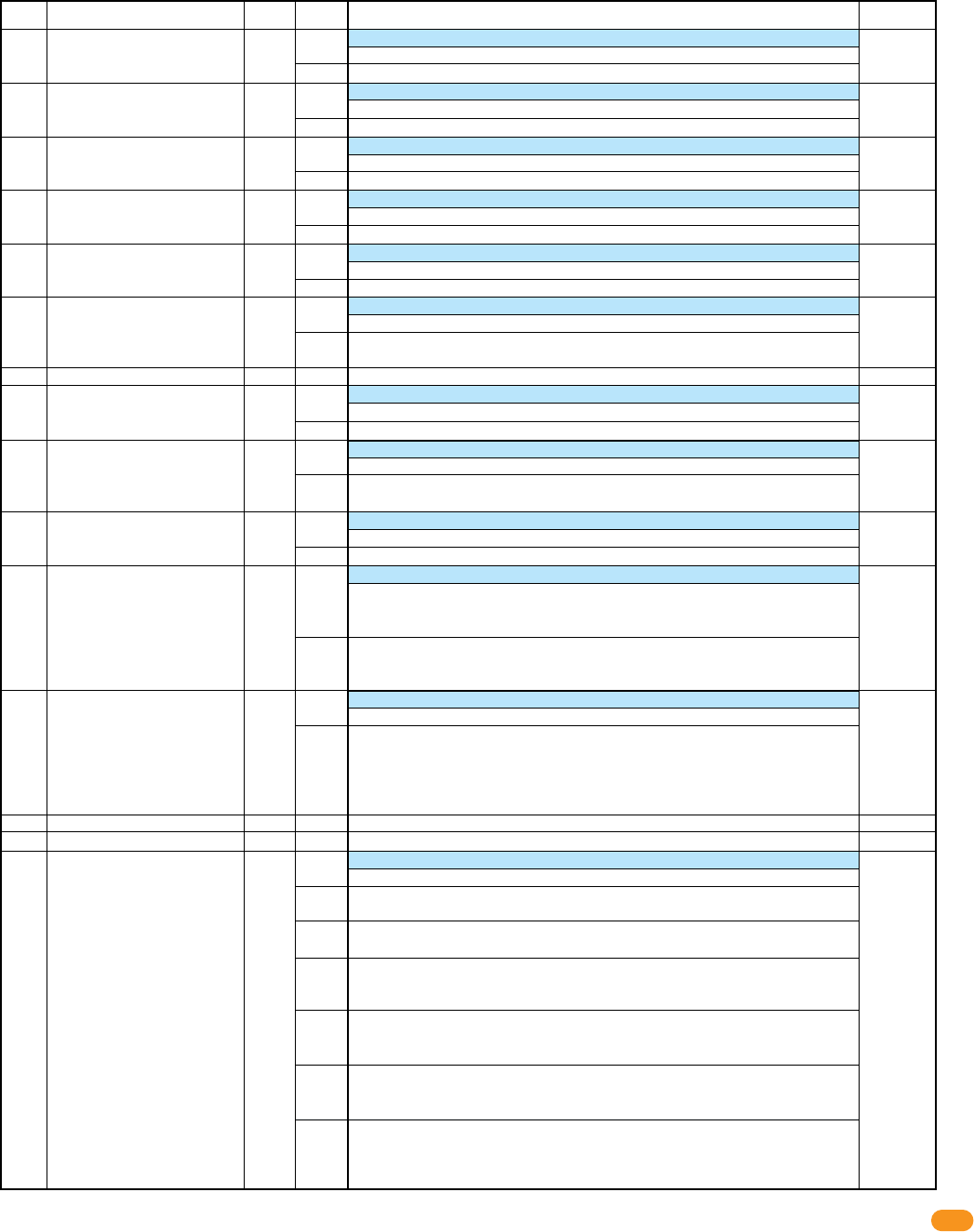
2358-065-T-5-18 27
Program
Step
Factory
Default
Description Options
Selection
Number Function
Select desired program steps and PHYSICALLY program EACH tracker expansion board being used with the access control system.
“Basic programming sequence on EACH board” on previous page explains how to program the functions into the board.
Programming Options on EACH Board
Sets Strike Time for output relay (term 25 & 26)
0.25 second strike time
Strike time in 1-second increments
Set Strike Time for RX
(Request to Exit)
of output relay (input at term 18)
0.25 second Egress Strike time
Egress Strike time in 1-second increments
Timer starts when valid access has been granted.
1 second Door Ajar Timer
Timer set in 5-second increments: 01 = 5 seconds, 10 = 50 seconds
Timer setting for Aux Relay activation in 5-second increments
1 second Door Ajar Timer
Timer set in 5-second increments: 01 = 5 seconds, 10 = 50 seconds
Set Strike Time for RX of Aux relay (ONLY available if Dual Door Mode step 12 is ON)
0.25 second Egress Strike time
Egress Strike time in 1-second increments
Set RX (Request to Exit) function. Activate Output Relay or do not Activate Output Relay
Do Not Activate Output Relay or Reader Beeper/LED when RX input is received
Activate Output Relay and Reader Beeper/LED for Free Exit Strike Time when RX
received
Sets type of Door Switch contacts
N.O. contact from door switch with Door Closed (Circuit Open - CO)
N.C. contact from door switch with Door Closed (Circuit Close - CC)
Turns on Auto Relock function (not available if Dual Door Mode, step 12 is ON)
Output Relay is activated for Strike Time
Door Contact Switch required. If door returns to closed position during Strike Time
door will “relock” after 1 second, even if strike time has not expired.
Sets how BEEPER or LED will function during Hold Open
When Hold Open occurs, Beeper or LED is active only during Strike Timer
When Hold Open occurs, Beeper or LED will remain active during Hold Open
Sets how Aux & Alarm Relay responds during Hold Open or Hold Egress situation
No Aux Relay functions. Alarm will be in “Reset”. If Alarm Relay is set for “integral”
mode, Alarm relay will not activate. If Alarm Relay set for “Bypass” mode, Alarm
Relay will activate for Hold Open period or Extended Egress Hold.
Aux Relay will function for all settings. If Alarm Relay is set for “integral” mode,
Alarm relay will not activate. If Alarm Relay set for “Bypass” mode, Alarm Relay will
activate for Hold Open period or Extended Egress Hold.
Sets Tracker to function as 2 Access Points (2 tracker addresses)
Disabled, Tracker functions as single access point
Dual Mode: Tracker functions as set board address and next sequential address
Card Read will be sent to controller as set board address, access is granted or denied
Card then sent as set address +1, access granted or denied. Aux Relay becomes 2nd
output relay. All other Aux Relay functions disabled. Door Contact switch becomes
RX for 2nd address.
Sets function for Aux Relay
Aux Relay Disabled
No Door Ajar Timer: Requires Door Contact Switch. Aux Relay activates when Door
Not Closed.
No Door Ajar Timer, Pulse: Requires Door Contact Switch. Aux Relay “pulses” when
Door Not Closed.
Door Ajar Timer: Requires Door Contact Switch. When door opens, start Door Ajar
Timer. When timer expires Aux Relay activates for Aux Relay timer or until door
closes, whichever occurs first.
Door Ajar Timer, Pulse: Requires Door Contact Switch. When door opens, start
Door Ajar Timer. When timer expires Aux Relay Pulses for Aux Relay timer or until
door closes, whichever occurs first.
Door Ajar, Pulse warning the ON: Requires Door Contact Switch. When door opens,
Pulse Aux Relay and start Door Ajar Timer. When timer expires Aux Relay ON for
Aux Relay timer or until door closes, whichever occurs first.
Door opens for any reason, Start Door Ajar timer and pulse Aux Relay. When Door
Ajar timer expires, start Aux Timer and continue Pulsing Aux Relay. When Door
Closes or both timers expire, turn off Aux Relay.
00
01 - 99
00
01 - 99
00
01 - 99
00
01 - 99
00
01 - 99
0
1
0
1
0
1
0
1
0
1
0
1
0
1
2
3
4
5
6
00 - 99
00 - 99
01 - 99
00 - 99
00 - 99
0 - 1
0 or 1
0 or 1
0 or 1
0 or 1
0 or 1
0 - 12
1
2
3
4
5
6
7
8
9
10
11
12
13
14
15
Door Strike Timer
Free Exit Timer, Strike Time
Door Ajar Timer
Aux Relay Timer
Free Exit Timer, Aux Relay
Free Exit, No Strike
Not Used
Door Switch Logic
Auto Relock
Beeper / LED Hold Open
Hold Open or Hold Egress
functions
Dual Door Mode
Not Used
Not Used
Aux Relay Functions
01:
1 second
01:
1 second
12:
60 secs
12:
60 secs
01:
1 second
01:
Activate
0:
Disabled
0:
0:
No Relay
Function
0:
Disabled
0:
Disabled
0:
N.O.
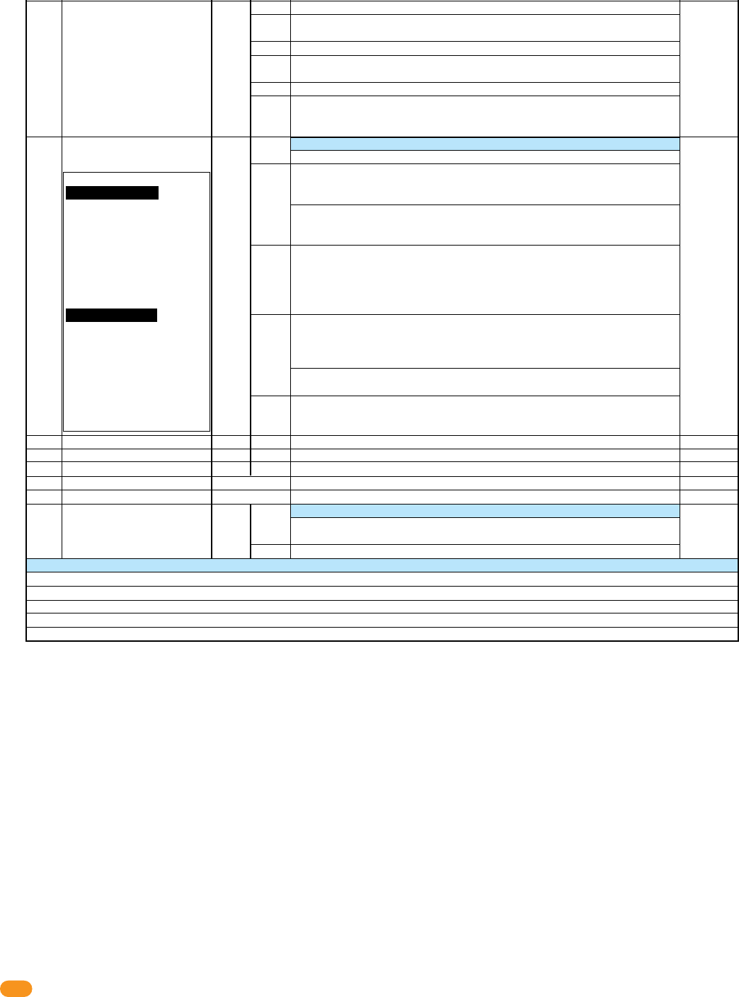
2358-065-T-5-18
28
Adjustable
LED Display
Door Operation Note:
PROPER Condition: The
access control system OR
request to exit device HAS
activated the OUTPUT RELAY
on the tracker expansion board
and the door contact switch is
CLOSED (Door is OPEN). This
indicates that the door has
been PROPERLY OPENED.
FORCED Condition: The
access control system OR
request to exit device has NOT
activated the OUTPUT RELAY
on the tracker expansion board
and the door contact switch is
CLOSED (Door is OPEN). This
indicates that the door has
been FORCED OPENED.
7
8
9
10
11
12
0
1
2
3
4
5
0
1
0 - 12
0 - 4
5
0 or 1
15
16
17
18
19
20
21
22
Aux Relay Functions
Alarm Relay Functions
Not Used
Not Used
Reset to Factory Defaults
View RF POT Setting
View RF Signal Loss
Card Code Forwarding
0:
Disabled
0:
Disabled
0:
Off
Aux Relay as 2nd Alarm Relay. Aux Relay will mirror Alarm Relay functions.
Aux Relay as 2nd Alarm Relay, PULSE. Aux relay will Pulse during any Alarm Relay
activation.
Good Card: Aux Relay will activate for Aux Relay timer for any Access Granted Card
Any Card: Aux Relay will activate for Aux Relay Timer when any card has been
presented.
Bad Card: Aux Relay will activate for Aux Relay timer when a card has been denied
Warn before Hold Open or Release of Hold Open: Aux relay will activate for Aux
Relay timer when scheduled Hold Open begins or ends. Output Relay will be delayed
until Aux Timer expires. Do not set Aux Timer above 60 seconds in this mode.
Sets function for Alarm Relay
Aux Relay Disabled
Bypass Mode: Alarm Relay provides “Bypass” to Alarm Door Switch. With proper
door input (access or egress) activate Alarm Relay, start Strike timer and Door Ajar
timer. When Door Ajar timer expires, deactivate Alarm Relay.
If second Door Contact Switch is provided, generate transaction for Door Ajar and
Door Closed following Door Forced condition. Also generate transaction for Door
Forced condition.
Integral Mode, Door Ajar Timer: Door Contact Switch connected to Tracker, Alarm
Relay provides connection directly to Alarm System. When door is opened for any
reason, start Door Ajar timer. When Door Ajar timer expires and Door is still OPEN,
activate Alarm Relay. Reset when door closes.
Send Door Ajar and Door Close transactions.
Integral Mode, Proper and Forced condition: Door Contact Switch connected to
Tracker, Alarm Relay provides connection directly to Alarm System. With proper door
input (access or egress) start Strike timer and Door Ajar timer. When Door Ajar
timer expires and Door is still OPEN, activate Alarm Relay. Reset when door closes.
If door is opened without proper condition, activate alarm relay. When door closes
deactivate Alarm Relay. Send Door Ajar, Door Close and Door Forced transactions.
Gate Alarm Function: Alarm Relay will activate for 1 second when tracker board
receives a “Gate Forced” or “Gate Obstructed” transaction from the operator control
board.
Sets all parameters to Factory Default
Sets maximum amount of allowable signal strength loss
Displays current signal loss between Base and Tracker.
Sets Wireless Tracker to act as Repeater
ONLY USE AS DIRECTED BY DOORKING TECH SUPPORT
Repeater Mode OFF
Repeater Mode ON
E1 - Relay connected to 4-pin terminal pins 1 & 2 is on for more than 5 seconds. Relay 1 in 1830 should be set for 00 seconds (0.25 second strike time)
E2 - Relay connected to 4-pin terminal pins 3 & 4 is on for more than 5 seconds. Relay 2 in 1830 should be set for 00 seconds (0.25 second strike time)
CO - One or more non-paired remotes has been detected but base unit's PAIRED switch is on.
A1 - Board address is invalid for Tracker. Board address is improperly set as 0, 1, 2 or 19.
A2 - Dual Mode - Bad Address, 18 or 19 not allowed.
Error codes on LED Displays for Base Station and Tracker
Rev-E 1-13-14

2358-065-T-5-18 29
4.3 Programming Step Descriptions
Sets the amount of time the door lock will remain unlock after the Output Relay has been activated (Terminals 25 & 26).
Program Step 1: Door Strike Timer
Sets the amount of time the door lock will remain unlock after the Request to Exit has been activated (Input at terminal 18).
Program Step 2: Free Exit Timer, Strike Time
Sets the amount of time the door contact switch (Input at terminal 15) can remain open until terminals 21 & 22 (Aux relay) and
23 & 24 (Alarm relay) will be activated. Timer will start after a valid access and egress has been granted.
Program Step 3: Door Ajar Timer
Sets the amount of time the aux relay will activate terminals 21 & 22. Timer will start after a valid access and egress has been granted.
Program Step 4: Aux Relay Timer
Sets the amount of time the aux relay will activate terminals 21 & 22 upon Request to Exit. This feature can ONLY be used when using
step 12 (Dual Door Mode).
Program Step 5: Free Exit Timer, Aux Relay
Sets how the door contact switch will operate. Normally Open (NO)/Circuit Open (CO) is typically used (Factory default setting of 0).
Normally Closed (NC)/Circuit Closed (CC) can be used if required (set to 1).
Program Step 8: Door Contact Switch Logic
When turned on (set to 1), will relock the door 1 second after door returns to closed position, even if the strike timer has not timed out. The
alarm relay and aux relay will NOT reset after door returns to closed position. A door contact switch is required for this feature. This feature
cannot be used when using step 12 (Dual Mode).
Program Step 9: Auto Relock
Sets how the card reader’s beeper or LED will respond when the door is held open longer than the programmed strike time. When turned on
(set to 1), will activate card reader’s beeper or LED on after strike timer has timed out.
Program Step 10: Beeper / LED Hold Open
When turned on (set to 1), one tracker expansion board will control 2 access points using the board address number that has been physically
set on the tracker expansion board and the next sequential board address number after that. When the access device gets activated from the
physically set tracker expansion board address number and access is granted or denied, the board will then automatically send out the same
access device information to the next sequential board address number to grant or deny access to the second access point. See section 3.8
for wiring.
Program Step 12: Dual Door Mode
When set to 0, Aux relay will NOT function. Alarm relay will “Reset” and if it is set for Integral mode (step 16), it will NOT activate.
If the Alarm relay is set for Bypass mode (step 16), it will activate after the Hold Open (Entry) or Hold Egress (Exit) timer has timed out.
When set to 1, Aux relay will function normally. Alarm relay set for Integral mode (step 16) will NOT activate.
If the Alarm relay is set for Bypass mode (step 16), it will activate after the Hold Open (Entry) or Hold Egress (Exit) timer has timed out.
Program Step 11: Hold Open or Hold Egress Functions
Program Step 6: Not Used
Program Step 7: Not Used
Program Step 13: Not Used
Program Step 14: Not Used
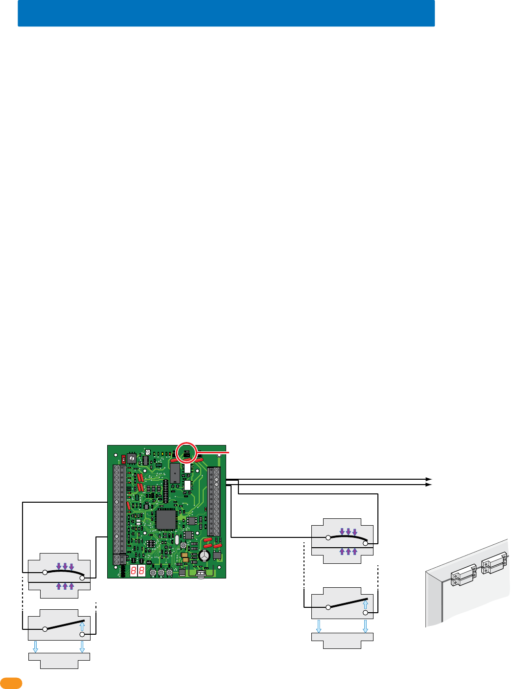
2358-065-T-5-18
30
Switch 1 Closed:
Door Closed
Switch 1 Open:
Door Open
N.C.
Com
N.C.
Magnet
SPST (NO)
SPST (NO)
Com
Optional
Switch 2 Closed:
Door Closed
Optional
Switch 2 Open:
Door Open
N.C.
Com
N.C.
Magnet
SPST (NO)
SPST (NO)
Com
4.3 Programming Step Descriptions Continued
Sets how the Aux relay will function (Terminals 21 & 22).
Set to 0, Aux relay is disabled.
Set to 1, No door ajar timer has been set. Requires a door contact switch. Aux relay will activate when door is not closed.
Set to 2, No door ajar timer has been set. Requires a door contact switch. Aux relay will pulse on and off when door is not closed.
Set to 3, Door ajar timer has been set. Requires a door contact switch. When door opens, door ajar timer starts. After timer expires, Aux relay
will activate for the Aux relay timer setting (step 4) or until door closes, which ever occurs first.
Set to 4, Door ajar timer has been set. Requires a door contact switch. When door opens, door ajar timer starts. After timer expires, Aux relay
pulses on and off for the Aux relay timer setting (step 4) or until door closes, which ever occurs first.
Set to 5, Door Ajar timer Pulse Warning. Requires a door contact switch. When door opens, door ajar timer starts and Aux relay pulses on
and off. After door ajar timer times out, Aux relay activates for the Aux relay timer setting (step 4) or until door closes, which ever occurs first.
Set to 6, Door Ajar timer Pulse continuously. Requires a door contact switch. When door opens, door ajar timer starts and Aux relay pulses
on and off. After door ajar timer times out, Aux relay continues to pulse on and off for the Aux relay timer setting (step 4) or until door closes,
which ever occurs first.
Set to 7, Aux relay is used as a second Alarm relay and will activate whenever the Alarm relay is activated.
Set to 8, Aux relay is used as a second Alarm relay and will pulse on and off whenever the Alarm relay is activated.
Set to 9, Good Card. Aux relay will activate for the Aux relay timer setting (step 4) when access is granted.
Set to 10, Bad Card. Aux relay will activate for the Aux relay timer setting (step 4) when access is denied.
Set to 11, Any Card. Aux relay will activate for the Aux relay timer setting (step 4) when any card is presented.
Set to 12, Warn before starting Hold Open and ending of Hold Open. Aux relay will activate for the Aux relay timer set duration (step 4) before
a scheduled hold open starts and then again when a hold open schedule is about to end. Step 4 MUST NOT be set for more than 60 seconds.
Program Step 15: Aux Relay Functions
Sets how the Alarm relay will function (Terminals 23 & 24). Note: Not all steps require a door contact switch wired to function.
Door Operation Note:
PROPER Condition: The access control system OR request to exit device HAS activated the Output Relay on the tracker expansion board and
the door contact switch is opened (Door is OPEN). This indicates that the door has been PROPERLY opened.
FORCED Condition: The access control system OR request to exit device has NOT activated the Output Relay on the tracker expansion board
and the door contact switch is opened (Door is OPEN). This indicates that the door has been FORCED opened.
Set to 0, Alarm relay is disabled.
Set to 1, Bypass Mode. Alarm Relay provides “Bypass” to Alarm the Door Contact Switch to the existing alarm system but it MUST be wired
as shown below. When door is opened under PROPER condition, Alarm relay will activate. Strike timer starts and Door ajar timer starts. When
Door ajar timer times out, alarm relay will deactivate.
If a second Door Contact Switch is provided and wired as shown below (Integral), tracker expansion board generates event transactions for
Door Ajar and Door Closed following Door Forced condition. It will also generate a event transaction for Door Forced condition.
Program Step 16: Alarm Relay Functions
34
33
32
31
30
29
28
27
26
25
24
23
22
21
14
15
16
17
18
19
20
13
12
11
10
9
8
7
6
5
4
3
2
1
ON
1
0
BOARD ADDRESS
0
9
8
7
6
5
4
3
2
1
NC
OUTPUT
RELAY
NO
NC
ALARM
RELAY
NO
NC
AUX
RELAY
NO
ENT
RESET
2358-010
RF
DATA
RF
SECURE
RF
STATUS
CODE
SENT
CODE
GOOD
CODE
BAD
Dry relay contacts connect
to existing alarm system.
Set Alarm Relay
jumper typically (NO).
#23-Alarm Relay
#8-Com
#15-Door
Ajar
Input
#24-Alarm Relay
Door Contact Switch N.O.
(Factory default setting
of 0 in program step 8)
Door
Switch 1 Switch 2
Optional
Door Frame
Door Contact Switch MUST be Wired
to Alarm Relay for BYPASS MODE
Alarm relay functions program step 16 continued on next page.
Bypass Mode allows
for continual door
security in the case
of power failure at
the tracker expan-
sion board and/or
access control
system when no
battery back-up
power is used.
Integral Mode
Wiring
Bypass Mode
Wiring
Note: Switch 2 can be
used in ByPass Mode.
It is Mandatory in
Integral Mode.

2358-065-T-5-18 31
4.3 Programming Step Descriptions Continued
Sets the maximum amount of allowable signal strength loss between the wireless tracker expansion board and the wireless baseboard (ONLY
works on WIRELESS tracker expansion board).
Program Step 20: Display RF Range Setting (Wireless ONLY)
Displays current signal loss between the wireless tracker expansion board and the wireless baseboard (ONLY works on WIRELESS tracker
expansion board).
Program Step 21: Display RF Signal Loss (Wireless ONLY)
ONLY USE THIS FEATURE AS DIRECTED BY DOORKING TECH SUPPORT. Sets wireless tracker expansion board to operate as a wireless
repeater and forward card codes (access codes) to the next board in the wireless system when the wireless signal range needs to be extended
(ONLY works on WIRELESS tracker expansion board).
Program Step 22: Card Code Forwarding, Tracker as Repeater (Wireless ONLY)
Sets all parameters to Factory Defaults (See table in section 4.2 for factory default settings).
Program Step 19: Reset to Factory Defaults
Program Step 17: Not Used
Program Step 18: Not Used
Program Step 16: Alarm Relay Functions Continued
Set to 2, Integral Mode Door Ajar Timer. Door contact switch (Input at terminal 15) connected to tracker expansion board (see previous
page for wiring). When door is opened, Door Ajar timer starts (step 3). If door is still open when door ajar timer times out, alarm relay will
activate. Alarm relay will reset when door closes. Door Ajar and Door Close event transactions will be sent from tracker expansion board to
access control system.
Set to 3, Integral Mode Proper and Forced Condition. Door contact switch (Input at terminal 15) connected to tracker expansion board.
Alarm Relay provides connection directly to Alarm System. If door is still open when door ajar timer times out, alarm relay will activate. Alarm
relay will reset when door closes.
If door is opened without Proper condition (see previous page), alarm relay will activate. Alarm Relay deactivates when door closes. Tracker
expansion board sends Door Ajar, Door Close and Door Forced event transactions to access control system.
Set to 4, Gate Alarm Function. Alarm Relay will activate for 1 second when tracker expansion board receives a “Gate Forced” or “Gate
Obstructed” transaction from the gate operator control board (DoorKing gate operators ONLY).

2358-065-T-5-18
32
SECTION 5 - TROUBLESHOOTING
Before beginning any troubleshooting, check all wiring and look for any loose connections. Double check your wiring! The
tracker expansion board in some applications may have over 20 wires connected directly to the board terminal strips. Be sure
that you have a good VOM (Volt-Ohm-Meter) to assist you when checking voltages and continuity.
Check the programming to be sure that the tracker expansion board is setup to operate as desired. If more that one tracker
expansion board is connected in the system, be sure the board addresses are set correctly.
Be sure that the tracker board is powered (16 VAC, 20 VA). The LEDs should be ON when power is applied to the tracker
expansion board. Battery back-up may be connected to the tracker expansion board as shown in section 3.7.
The wiegand device (card reader, RF receiver, digital, etc.) must output data in the 26, 30, 31-bit wiegand format. The tracker expansion
board is not capable of receiving any other wiegand format.
The wiegand device must be connected to terminals #6-#7-#8-#9 as described in section 3.3 of this manual.
Two wiegand devices may be connected in parallel to the wiegand input on the tracker expansion board. Be aware that both devices will
appear to the access control system and the Remote Account Manager software as the same device.
Power for the wiegand devices is provided on terminals #8 (common) and #9 (+10 to +12 VDC). To check this power:
1. Set your VOM to the 50-volt DC range.
2. Connect the positive lead (red) to #9 and the negative lead (black) to #8. The meter should indicate +10 to +12 volts DC.
The tracker expansion board outputs data on terminals #27-#28-#29. When the tracker expansion board is sending data to the access control
system on these lines, the LED near these terminals will light. The voltage to operate these terminals comes from the access control system.
Normal voltage on these terminals is +4.5 to +5 volts DC. To check this voltage:
1. Set your VOM to the 50-volt DC range.
2. Connect the negative (black) lead to #27 and then check #28 and #29 with the positive (red) lead. The meter should indicate +4.5 to
+5 volts DC.
The data from the wiegand devices is inputed to the tracker expansion board on terminals #6 and #7. The normal voltage for these terminals
are +4.5 to + 5 volts DC. This can be checked by connecting the negative (black) lead of your meter to #8 and then checking for voltage with
the positive (red) lead on terminals #6 and #7.
When a wiegand device sends data to the tracker expansion board on terminals #6 and #7, the LED's associated with these terminals will
flash. These flashes are very fast and may be difficult to see. If a 26, 30, 31-bit wiegand input is received, the tracker expansion board
makes the lines on terminals #2 and #4 busy to prevent the gate operators from sending any transactions. It then checks for a busy signal on
terminal #10. If this pin is not busy, the tracker expansion board will make this pin busy itself and then wiegand out the data to the access
control system (If terminal #10 is busy, the tracker expansion board simply waits for this terminal to go un-busy and then sends the data).
After the tracker expansion board sends the data, it will wait for a reply from the access control system (The wiegand output LED will flash
when the data is sent to the access control system). Once the data is received by the access control system, the access control system will
make the decision to grant or deny access. If the decision is to deny access, the tracker expansion board will release the busy signal on
terminal #10, and will not activate it’s output relay. If the decision is to grant access, the access control system will activate its relay, which
causes the tracker expansion board to activate its output relay, and then releases the busy signal on terminal #10 allowing other tracker
expansion boards to communicate with the access control system.
The above operating sequence takes place in less than one second. In applications where the system is operating at its maximum (48 tracker
expansion boards), and in the unlikely event that all devices are activated at precisely the same moment in time, there could be a delay of a
few seconds for the last tracker expansion board to activate its output relay if the access control system decides to grant access to the person
using the device connected to this tracker expansion board.
5.1 Wiegand Device Data

2358-065-T-5-18 33
Be sure that the gate operator has Gate Tracker capability. This can be determined by checking the revision letter of the control board in the
operator. Gate operator control boards with Gate Tracker capability are listed below.
• 4402-010 Rev A or higher. 1150 overhead gate operator
• 4100-010 Rev AA or higher. 6524 swing and 9024 slide gate operators (AC Powered ONLY)
• 4404-010 Rev A or higher 9200, 9500 slide gate operators
• 4405-010 Rev A or higher. 6500 swing and 9000 slide gate operators
• 4502-010 Rev A or higher. 6050, 6100, 6300 swing gate operators
• 4602-010 Rev A or higher. 9100, 9150 slide gate operators
• 1601-010 Rev Q or higher. 1601, 1602, 1603 barrier gate operators
If the control board that you are working with has a lower revision letter than those listed above, the control board does not have the capability
to send operator data to the tracker expansion board.
The Gate Tracker outputs from the 4402, 4404, 4405, 4502 and 4602 control boards must be wired to tracker expansion board terminal #1, #2
#5. Gate Tracker outputs from the 1601 control board must be wired to tracker expansion board terminals #3, #4, #5.
Normal voltage at terminals #1, #2, #3, #4 is -8 to -12 VDC. To check this:
1. Set your VOM to the 50-volt DC range.
2. Connect the positive lead (red) to terminal #5, then touch the negative lead (black) to terminals #1-#2-#3-#4. Each should indicate 8
to 12 volts on your meter. Note: the meter reading is actually a negative voltage because the positive lead of your meter is connected to
a common point (terminal #5). If you reverse the meter leads, the needle should move off scale to the left indicating a negative voltage.
3. As the tracker board is receiving data from the gate operator on terminals #1 or #3, the LED's associated with these terminals will
light and the voltage on terminals #1 or #3 will go positive. Note: the transfer of data from the gate operator to the tracker board is
extremely fast. It may be difficult to see the LED's light and unless you have a very good digital type meter, measuring the voltage
change from negative to positive will be very difficult.
4. The tracker board will send a busy signal back to the gate operator on terminals #2 or #4. When this happens, the LED's associated
with these terminals will light and the voltage on terminals #2 or #4 will go positive. Note: the busy signal from the tracker board to the
gate operator is extremely fast. It may be difficult to see the LED's light and unless you have a very good digital type meter, measuring
the voltage change from negative to positive will be very difficult.
5. After the tracker board has received the data from the gate operator, it will send the data to the access control system. When this
happens, the wiegand output LED (terminal #29 LED) will light, and the tracker board busy LED (terminal #10 LED) will light. After the
data has been sent, these LED's will turn OFF.
6. The tracker board cannot receive any data if the busy LED (terminal #10 LED) is ON.
5.2 Gate Operator Data

2358-065-T-5-18
34
The tracker expansion interface board sends the following gate operator data to the DKS access control system. This data is stored in a
separate file in the access control system and can be viewed by clicking the GATE button on the transaction report screen in the DoorKing
Remote Account Manager for Windows software. Each event is date and time stamped.
Gate Operate 100 Times
Gate Forced
Gate Hit Obstruction
Gate Power On
Gate Key 1 On 5 Minutes
Gate Key 2 On 5 Minutes
Gate Reverse On 5 Minutes
Gate 5/14 On 5 Minutes
Gate Input On 5 Minutes Rels
Gate Stop On 5 Minutes
Gate Reverse Loop On 5 Minutes
Gate Exit Loop On 5 Minutes
1601 Up On 5 Minutes
1601 Down On 5 Minutes
1601 Up Loop On 5 Minutes
1601 Up Loop Down 5 Minutes
1601 Power On
1601 Input On 5 Minutes Rels
Pedestrian Gate Stuck Open
Pedestrian Gate Closed
1601 Hit Obstruction
Gate Open On 5 Minutes
Gate Close On 5 Minutes
Gate 1 Power Off
1601 Power Off
Open Beam On 5 Minutes
Close Beam On 5 Minutes
Open Edge Activated
Close Edge Activated
Gate Shut Down
Reset Pushed
Alarm On
Reset Pushed
Beam On 5 Minutes
Transaction sent each time gate operator goes through 100 operations. If 10 of these
transactions show on report, the operator has cycled 1000 (10 x 100) times.
An attempt was made to force open the gate.
The Type A (inherent) entrapment prevention device was activated.
Power applied to the operator control board.
Input is activated continuously (shorted) for at least 5-minutes.
Input is activated continuously (shorted) for at least 5-minutes.
Reverse input is activated continuously (shorted) for at least 5-minutes.
Partial open input is activated continuously (shorted) for at least 5-minutes.
Shorted input has been cleared.
Stop (3-button) input is activated continuously (shorted) for at least 5-minutes.
Detector plugged into control board reverse port activated at least 5-minutes.
Detector plugged into control board open port activated at least 5-minutes.
Up input to 1601/1602 operator activated continuously for at least 5-minutes.
Down input to 1601/1602 operator activated continuously for at least 5-minutes.
Detector plugged into control board up port activated at least 5-minutes.
Detector plugged into control board down port activated at least 5-minutes.
Power applied to the operator control board.
Shorted input has been cleared.
Alarm relay activated on 2358 tracker expansion board.
Alarm reset activated on 2358 tracker expansion board.
The Type A (inherent) entrapment prevention device was activated.
Open (3-button) input is activated continuously (shorted) for at least 5-minutes.
Close (3-button) input is activated continuously (shorted) for at least 5-minutes.
Power applied to the operator control board has been lost.
Power applied to the operator control board has been lost.
Input is activated continuously (shorted) for at least 5-minutes.
Input is activated continuously (shorted) for at least 5-minutes.
Reverse edge has been activated.
Reverse edge has been activated.
Slide gate hard shutdown, entrapment alarm activated.
Slide gate reset button activated.
Swing gate hard shutdown, entrapment alarm activated.
Swing gate reset button activated.
Swing gate beam input is activated continuously (shorted) for at least 5-minutes.
5.3 Gate Operator Event (transaction) Reports
Event (transaction) Description

2358-065-T-5-18 35
Filling out this form will allow you to better keep track of the entire system at a glance. This will assist you when programming the system
and/or any maintenance information about the system that may be required in the future.
5.4 Complete System Information
Board Address #
# 3
Location and/or Description Board Serial # and Rev Letter
Relay 2 / Wiegand 2 Access Control System Connection
Board Address # 3-10

2358-065-T-5-18
36
Filling out this form will allow you to better keep track of the entire system at a glance. This will assist you when programming the system
and/or any maintenance information about the system that may be required in the future.
5.4 Complete System Information Continued
Board Address #
# 11
Location and/or Description Board Serial # and Rev Letter
Relay 1 / Wiegand 1 Access Control System Connection
Board Address # 11-18

2358-065-T-5-18 37

www.doorking.com
DoorKing, Inc.
120 S. Glasgow Avenue
Inglewood, California 90301
U.S.A.
Phone: 310-645-0023
Fax: 310-641-1586
Provides Access Control System Expansion to
Manage Up to 48 Additional Access Points.
Use this manual for circuit board 2358-010 Revision L or higher.
HARDwired Installation/
Owner’s Manual
For Models:
1833, 1835, 1837 and 1838 Multi-Door Access Controller
Tracker Expansion Board
Tracker Expansion Board
Tracker Expansion Board
Tracker Expansion Board
Wiegand Compatable
Conforms To UL STD 294
2358-065-T-5-18
