DormaKaba Multihousing InSync CP Installation Instructions 6 3 08 In Sync 10936761
User Manual: DormaKaba Multihousing InSync CP Installation Instructions Installation Instructions
Open the PDF directly: View PDF ![]() .
.
Page Count: 2
InSync® CP Installation Instructions Pg. 1 of 2
InSync® CP
Installation Instructions
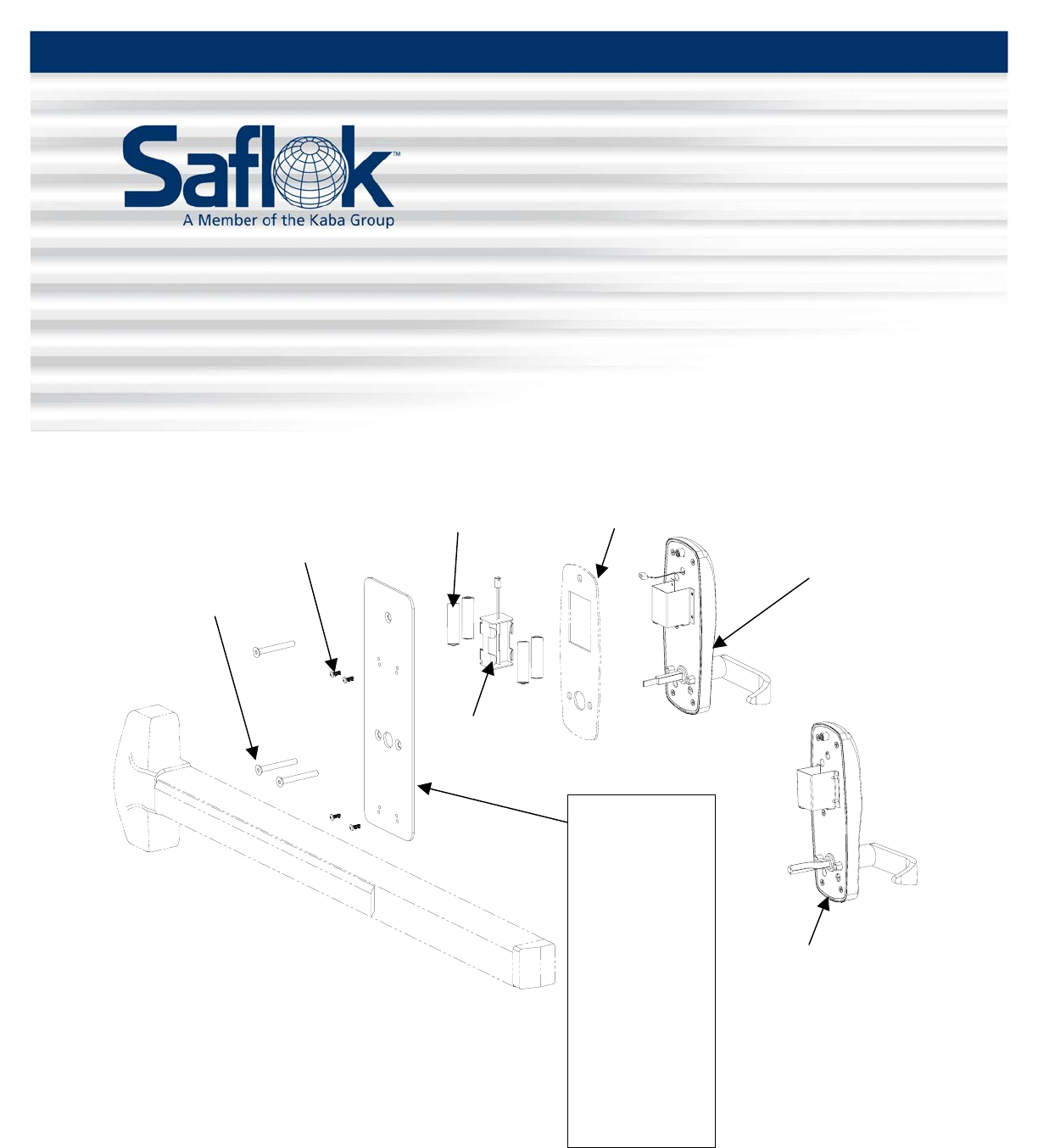
All parts needed to install the InSync® CP lock are included with each unit. Check to make sure all
parts are accounted for before beginning installation. Do not substitute any of the parts. The use of
substitute parts will result in poor performance of the lock.
Panic Bar
Optional, order
separately
Underplate
R23310-Color
Von Duprin,
Dorma 9300 Rim &
9400 Vertical
R22230-Color
Monarch Rim
R22300-Color
American Eagle Rim
R23240-Color
Sargent 888F Rim
R22290
Monarch 18V
Vertical
Part may vary from
the illustration
R27120
Exterior Gasket
Optional, order
separately
R28200
Battery Holder
R27170-Color
1/4-20 2-1/8 x
Screws
R20270-A-X-L-PCB-C
Outside Chassis Assembly
S16965
Batteries
10-32 x 5/8
RH PH Screws
Quantity varies with
p
anic bar
R20270-C-L-H
Outside Chassis Assembly
For Monarch Rim Panic Bar
All information contained herein, including but not limited to product pricing and other intellectual property, is confidential and
intended for the sole use of the addressee(s) so named. Any misuse of this confidential information contained herein may result in
legal action by Computerized Security Systems dba SAFLOK and its parent company.
© SAFLOK™ WL 6/3/2008
InSync® CP Installation Instructions Pg. 2 of 2
Installing the InSync® CP Lock
Note: Refer to the installation instructions packed with your panic bar as you install the InSync CP lock.
1. Prepare the door and door frame using the InSync CP installation template and the appropriate panic
bar door prep template.
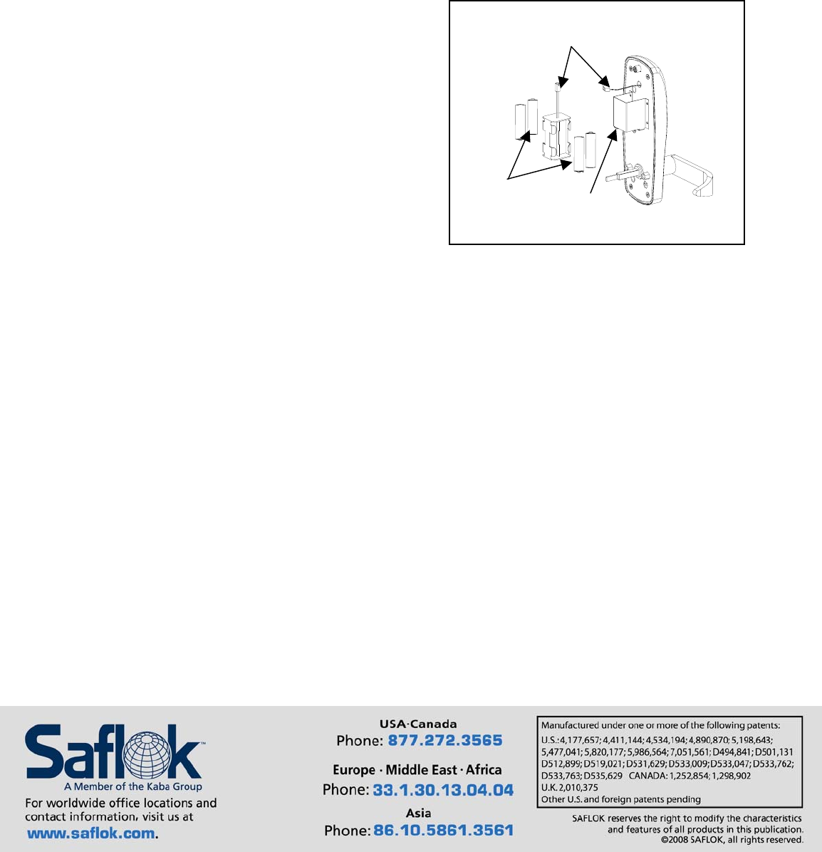
Battery
Cables
Batteries
Housing
2. Place the batteries in the holder and slide the battery
holder into the housing on the back of the lock
assembly.
3. Connect the battery cables.
Important: When the battery cable is connected,
watch for the LED on the outside of the lock to flash.
4. Secure the outside trim assembly to the door using the three 1/4-20 x 2-1/4 screws and underplate
provided.
Note: Be sure that the spindle is properly engaged in the panic bar mechanism.
5. Install the panic bar, following the installation instructions specific to your panic bar.
Important: Before closing the door, check lock function using the construction key, outer lever, and
panic bar.
Questions? Call Customer Service at 800.999.6213 and select option 3.
For online assistance, visit support.saflok.com.
© SAFLOK™ WL 6/3/2008
