Draeger Safety 001 Fire Fighter Telemetry Entry Control Board User Manual 3351236
Draeger Safety Ltd Fire Fighter Telemetry Entry Control Board 3351236
Users Manual

Edition B: April 2005 1
Contents Page No.
For Your Safety 02
General 02
Power Packs 02
Liability Statement 02
Introduction 03
Description and Intended Use 04
The Entry Control Board 04
The Data Radio Unit 10
Getting Started 12
In Use 17
Pre-Entry Procedure 17
Making Contact 18
Monitoring Data – Entry Control Board 22
In Use - Communication 25
From ECB to Sentinel 25
From Sentinel to ECB 27
Loss of Radio Contact (ECB to PU) 30
After Use 31
Log Off Procedure 31
Service Information 34
Setting Time Display 34
Setting Date Display 34
Display Test - ECB 35
Encoding a Tally 36
Removing/Fitting Battery Packs 38
Care 39
Faults - Causes - Solutions 40
Technical Data 42
Order List 43

Edition B: April 2005
2
For Your Safety
This User Instruction for the DrägerMan PSS® Merlin® Telemetry System must be used in conjunction
with the User Instruction supplied with the DrägerMan Sentinel Series electronic signal and warning unit
and the associated self contained respiratory protection apparatus (SCBA).
General
lUse of the equipment requires training and observance of this User Instruction together with User
Instruction supplied with the associated equipment.
lUse the equipment only for the purpose as specified in this User Instruction or as confirmed in
writing by Dräger.
lOnly trained competent personnel should inspect and service the equipment at regular intervals
and a record kept of such inspections and service.
lDräger recommends a service contract be obtained from your Dräger branch or Agent.
lContact Dräger for details of Service Contracts and Training Courses.
lNotify Dräger if there is a component fault or failure.
lUse only original Dräger Spare Parts for service and maintenance.
lUse only Dräger Test Equipment for service and maintenance.
lThe Merlin ECB and Portable Unit meet the FCC requirements regarding exposure of human beings
to radio frequency radiation. Occupational/Controlled limits apply when persons are exposed to
radio frequency radiation as a consequence of their employment provided these persons are fully
aware of and exercise control over their exposure. Awareness of exposure can be accomplished by
use of warning labels or by specific training or education through appropriate means, such as an RF
safety program in a work environment.
Warning: All electronic devices may suffer from a temporary loss of function, e.g. during high levels of RF
radiation. Following a temporary loss of function with the DrägerMan Entry Control Board (ECB), the
microprocessor will reset and record this event as an ‘ECB Reset’ in the datalog. Any displayed alarm
LEDs will be cleared. All previously ‘Logged On’ data radio units will be automatically re - ‘Logged On’.
Full operational and functional features will reactivate and the ECB will continue to operate with no loss
of performance. It should be noted that up to 15 minutes of datalog events could be deleted.
Power Packs
Used power packs
lDo Not Incinerate – risk of explosion.
lDo Not puncture the battery casing – risk of explosion.
lSpecial waste disposal – according to local waste disposal regulations. Information on this subject
should be available from the local environmental and regulatory agencies and waste disposal companies.
Liability Statement
Responsibility for reliable function of this equipment and any approved ancillary units transfers to the
owner or operator when the equipment is serviced, or repaired by untrained personnel, (not employed or
authorised by Dräger) or when used in a manner not conforming to its intended use.
Dräger cannot be held responsible for damage caused by non-compliance with the recommendations
given above.

Edition B: April 2005 3
The Warranty and Liability provisions of the Terms of Sale and Delivery are likewise not modified by the
recommendations given above.
Changes or modifications to the equipment not expressly approved by Dräger Safety could void the
user’s authority to operate the equipment.
Introduction
When the decision is taken to use self-contained respiratory protection apparatus (SCBA) in a life
threatening hazardous environment, it is essential that an effective control procedure is in place to
manage, monitor and safeguard the wearer of the equipment.
In the United Kingdom, the Technical Bulletin – Breathing Apparatus/Command and Control Procedures,
together with the Manual of Firemanship, provide guidance for Fire Authorities and Firefighters in the
introduction, application and management of a risk based approach to the wearing of breathing apparatus.
The DrägerMan PSS® Merlin® Telemetry System package further enhances and supports these control
procedures by providing a means of remote 2way digital data and alert status communication between
the wearer of the self contained respiratory protection apparatus and an external support control module.
To achieve this communication, the DrägerMan PSS® Merlin® Telemetry System modules (Entry Control
Board and Data Radio Unit) interface with the DrägerMan Sentinel Series electronic signal and warning
unit fitted to the self contained respiratory protection apparatus.
It is important to be aware that communication can be affected by a breakdown in the transmission signal
due to extremes of application scenarios such as long distance, building construction, below ground
structures etc. Dräger offer the DrägerMan Repeater, which is a system module option designed to
provide a means of enhancing the signal effectiveness in harsh environments. Contact Dräger for details.

Edition B: April 2005
4
Description and Intended Use
The Entry Control Board
The DrägerMan PSS® Merlin® Entry Control Board (ECB) is a battery-powered unit incorporating an
integral digital radio transmitter and receiver with associated antenna. The ECB has twelve channel slots
each able to accept the encoded tally of an individual Data Radio Unit. Inserting the tally activates the
transmission link monitoring capability between the ECB, the Data Radio Unit and the DrägerMan
Sentinel Series electronic signal and warning unit combination.
Entry Control Boards are individually programmed with a unique identity code (e.g. Fire Brigade Identity
Code or a User Code) together with the allocated Board Identification (ID) Number.
The data transmission link (Log On) between the Entry Control Board and each Data Radio Unit and
Sentinel combination is activated following the insertion of an encoded transponder ‘Tally Key’ into any
of the available channels of the board. The ‘Tally Key’ is encoded with the same codes as the corresponding
Data Radio Unit.
The ECB identifies the associated Data Radio Unit/Sentinel combination and the On-Line radio icon
illuminates (Green) continuously, confirming a successful radio link with the Sentinel. The individual
channel screen defaults to show the actual ‘Time of Whistle’ information.
At an incident, the use of the Entry Control Board (ECB) is normally the responsibility of an Entry
Control Officer (ECO). The ECO must ensure that agreed control procedures are in place to manage,
monitor and safeguard the wearer of the breathing apparatus.
To support any possible requirement for incident analysis information, the ECB stores and maintains an
‘Event Log’ (datalog) that can be downloaded to a computer. Contact Dräger for full details of
associated software.
For positive and secure support of the ECB at and during an incident a support bracket is available
(see order list) for fitment to a tripod unit.
Receiving Information
The On-line Signal radio icon illuminates (Green) at each channel of the ECB indicating satisfactory
radio contact with the associated Data Radio Unit and Sentinel combination.
The ‘Time of Whistle’ (TOW) default shown on the individual channel screens is calculated automatically
by the ECB by adding the initial TTW value transmitted at the initial Log On of the Sentinel, to the actual
time shown on the real time clock of the ECB.

Edition B: April 2005 5
The following additional on going data is communicated to the ECB every 20 seconds from each ‘Logged
On’ Data Radio Unit and Sentinel combination:
lTime to Whistle (TTW).
lPressure.
lTemperature of the Sentinel.
By pressing the information button of the ECB, a controller is able to scroll between the Time of
Whistle, Time to Whistle, Pressure, and Temperature. The Time to Whistle information is the default
data displayed on the Sentinel.
Additionally, the Time Elapsed from activating the Sentinel to ‘operational mode’ can be displayed.
The above information is displayed on the individual channel screens of the ECB and the defaults and
data sequence can be configured to meet the requirement of the end user. Contact Dräger for details.
Additional alert status signals received from the Data Radio Unit are:
lAutomatic Distress Signal Unit (ADSU) alarm signal – movement sensor.
lManual Distress Signal – panic button.
lVoluntary Withdrawal.
Each of these signals is differentiated and identified on the ECB by separate illuminated icons.
Transmitting Information
The ECO is able to activate the following transmissions from the Entry Control Board to each ‘Logged
On’ Data Radio Unit:
lAcknowledgement of a Voluntary Withdrawal transmission from the Data Radio Unit.
lSelective Evacuation - evacuation command to a specific Data Radio Unit or Units (team).
lEvacuation Signal – simultaneous evacuation command to all ‘Logged On’ Data Radio Unit.
lAcknowledgement of ADSU or Panic Alarm.
Manually Recorded Information
Adjacent to each of the channel screens is rectangular white panel areas. Using a waterproof marker
(e.g. China Graph Pencil), these can be used to record any relevant data regarding any individual or
defined teams, e.g. location of the wearer, location of the team, team reference etc.
If required the board can be photographed to provide any evidential requirement of an incident.
Edition B: April 2005
6
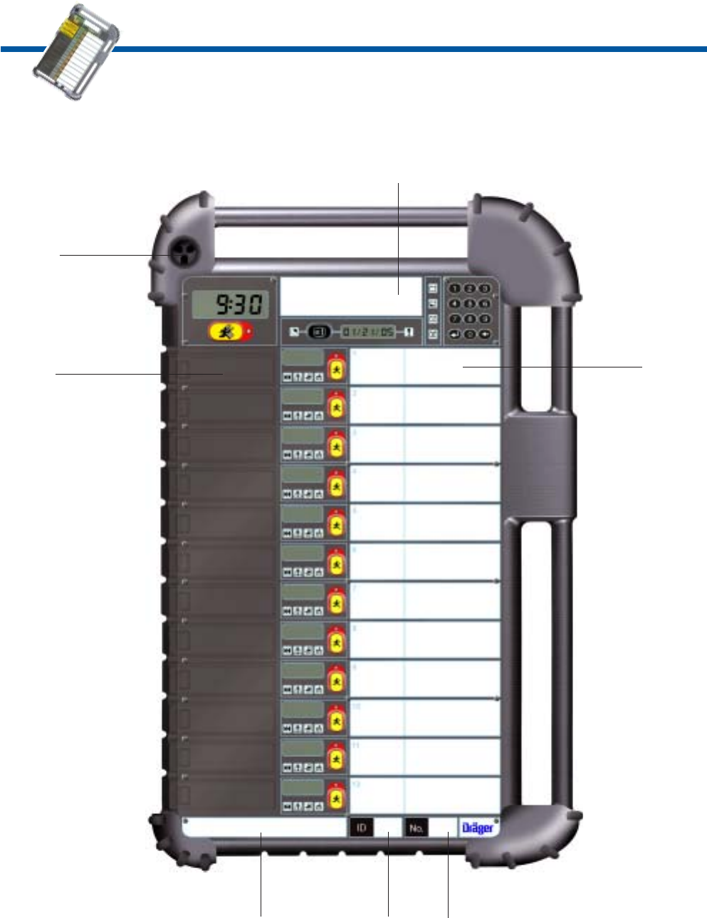
1 Tally Channel Slot
2 Audible Alert Sounder
3 Clear label (marker or slide in label)
4 Remarks Panel
5 Label - Board Identification Number
6 Label - User Identification Number
7 Clear Label (marker or slide in label)
Entry Control Board - Front
1(x12)
2
3
4 (x12)
657
1541USA
Edition B: April 2005 7
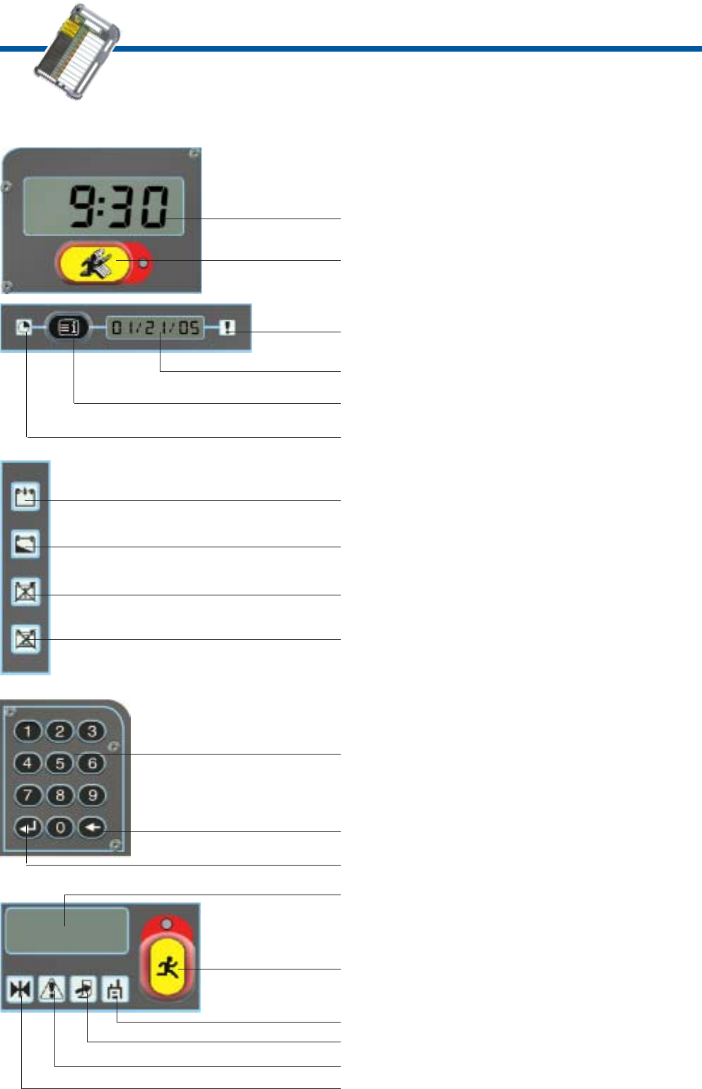
Default - Time of Whistle (TOW)
or - Time to Whistle (TTW) - Green
Numeric Key Pad
Backspace Key Function
Enter Key Function
LED Display - Charging - Green
LED Display - Low Battery - Amber
LED Display - Battery 2 - Fail - Red
LED Display - Battery 1 - Fail - Red
LED Display - Distress Signal from non logged
on device - Red
LCD - Display Status Data Screen
Information Button - Display Status
LCD Time Clock Display Screen
Evacuation Button - All - Red
Detail of Elements
LCD Display - SCBA Information
Single Evacuation/Acknowledgement Button
LED Display - Online Signal - Green
LED Display - Withdrawal Alert - Amber
LED Display - Panic Button Alarm - Red
LED Display - ADSU (Motion) Alarm - Red
1436
1437USA
1438
1439
1440
Edition B: April 2005
8
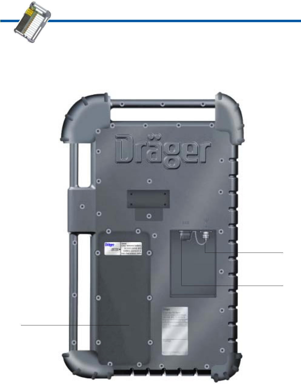
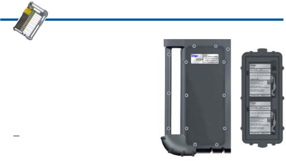
Entry Control Board - Back
1 Battery Cover
2 Connector - Charging
3 Connector - External Antenna
1
2
3
1543
Edition B: April 2005 9
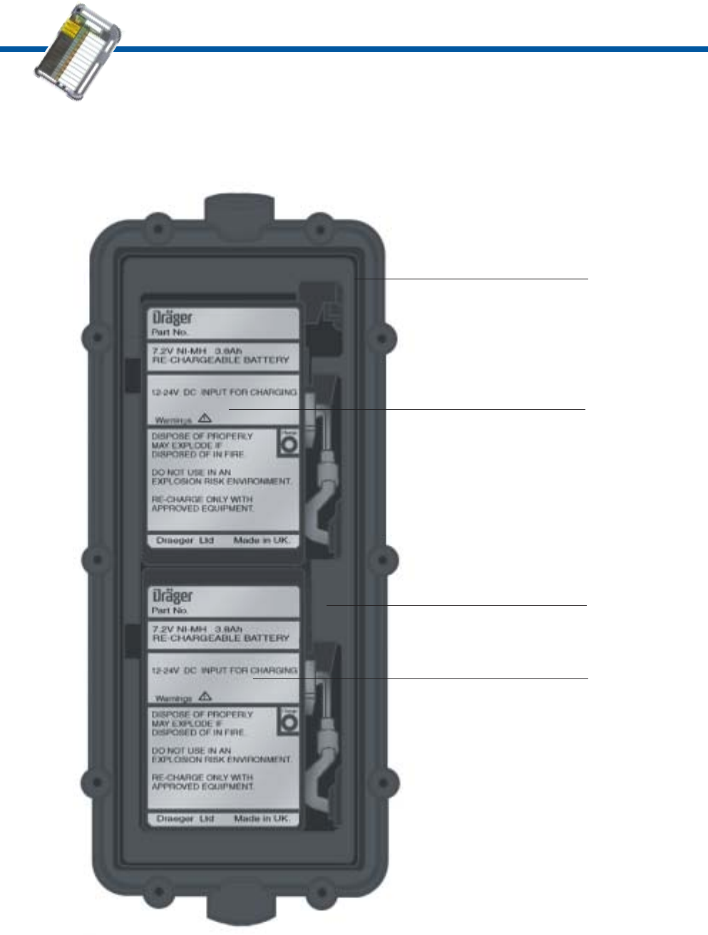
3
4
1
2
Battery Compartment
1 Battery 1
2 Battery 2
3 Gasket
4 Foam Insert
1492

Edition B: April 2005
10
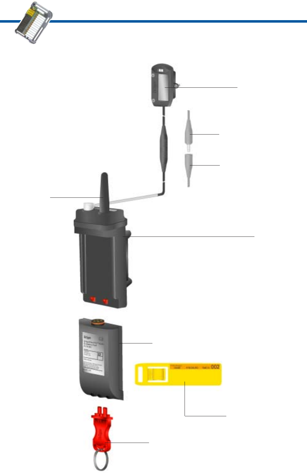
The Data Radio Unit
The DrägerMan PSS® Merlin® Data Radio Unit is a battery-powered unit incorporating an integral digital
radio transmitter and receiver with associated antenna. A cable and connector from the radio module
connects to an infrared interface to a DrägerMan Sentinel. The integrated assembly is able to transmit
data to communicate audible and visual alarm signals to the associated DrägerMan PSS® Merlin® Entry
Control Board.
The radio of the Data Radio Unit is programmed with an identification code for the unit (radio) together
with a unique identity code (e.g. Fire Brigade Identity Code or a User Code).
Supplied with each Data Radio Unit is a matching transponder ‘Tally Key’ that is encoded with the same
codes as the corresponding Data Radio Unit. A label on the ‘Tally Key’ identifies the users identification
code for the corresponding radio.
Included on the ‘Tally Key’ are markings with spaces that allow the following information to be added to
the tally using a suitable waterproof marker:
1. The name of the wearer.
2. The cylinder contents pressure on activation of the Sentinel is shown.
3. The actual ‘Time In’ to the risk area – shown on the clock of the Entry Control Board.
In the case of incidents where a possibility of radiation risk may be present, a Dosimeter reading (prior
to entry and after exit) may be recorded if necessary on the reverse side of the tally.
When the ‘Tally Key’ is inserted into any of the available channels of the Entry Control Board, the ECB
identifies the associated Data Radio Unit/Sentinel combination and the digital communication link is
activated. The ‘Green’ and ‘Red’ LEDs of the IR Link Unit on the rear of the Sentinel ‘flash’ intermittently.
A release key is available to unlock and detach the battery pack from the radio module.
Edition B: April 2005 11
IR Link/Battery Cover
- Sentinel
Radio Module
Tally Key (I.D. Encoded)
Battery
Release Key - Battery
The Data Radio Unit
Antenna
Male
Connector
Female
Connector
1493USA

Edition B: April 2005
12
Getting Started
The Entry Control Board
Power Supply
The battery compartment at the rear of the entry control board (ECB) provides space for two 7.2V
rechargeable nickel hydride (NiMH) batteries each running in parallel and providing 3.8Ah of power.
Continuous operating time is a minimum of 8 hours between recharge.
If necessary the ECB can be operated with the charging connector in place and connected to an
independent power source.
Charging the Batteries
The Entry Control Board is supplied without the batteries charged or fitted. A screw-lock connection
plug is provided in the recess in the rear panel of the entry control board to charge the batteries when
they are assembled in the board.
Important Note: The battery must be charged before initial use.
The batteries can however be charged individually. Refer to the Service Instructions - Fitting/Removal
of the batteries.
The following charging accessories are available:
lUniversal Power Supply (AC) Pack
lPower Cord for Universal Power Supply (AC) Pack connection.
lCharging Lead including screw adaptor and with socket for jack plug (direct to ECB).
lCharging Lead including twin plug adaptor and with socket for jack plug (direct to battery).
Refer to the label attached to the Universal Power Supply (AC) to check that the electrical main supply
voltage corresponds to the specified voltage requirement indicated on the label.
Important Note: The temperature of the battery is measured by a thermistor in the battery cell. To
protect the battery, the charging process will stop if the temperature of the battery is below 32oF (0oC)
or exceeds 113oF (45oC).
Optional charging kits are available for use with vehicle charging installations. Contact Dräger for details.
Safety Note: Charging units are not approved to the same intrinsic safety standard as is applied to the
wearer Data Radio Unit. Do Not attempt to charge batteries underground or in an area designated as,
or subject to an explosion hazard.
Edition B: April 2005 13
Charging Procedure – Single Battery
lConnect the plug adaptor of the charging lead to the battery. The Green charge LED on the front
panel of the battery will illuminate.
lWhen the LED begins ‘flashing’ this indicates either:
1. Full 14 hour charge has been applied OR
2. Main charging has been suspended due to the battery cell temperature being either below
32oF (0oC) or above 113oF (45oC).
lAfter charging, press and hold the release tab of the connection plug adaptor of the charging lead
and remove the plug from the battery connector. See the Service Section for instructions on fitting
and removing the battery.
Note: The battery can remain connected to the charger without any damage to the battery.
Charging Procedure – ECB
lRefer to the Service Instructions - Fitting/Removal of the batteries.
lUnscrew the protective cap from the charging connection then connect the screw adaptor of the
charging lead.
lDuring charging, the Green LED on the front panel will illuminate continuously and the date
display changes to indicate the level of charge as shown by a series of ‘dash/dot’ elements.
lA ‘flashing’ LED indicates a full charge, and the number of ‘dash - dot’ elements
provide an indication of the level of charge, e.g. eight ‘dash/dot’ elements indicate 100% charge.
Disconnect the screw adaptor of the charging lead and refit the protective cap
Important Note: If only six or less ‘dash/dot’ elements are shown at the end of the charge, this indicates
that one or both batteries are in suspect condition. Replace both batteries.
Note: The ECB can remain connected to the charger without any damage to the batteries. If necessary
the ECB can be operated (telemetry mode) with the charging connector in place when connected to an
independent power source. In telemetry mode the charging will be suspended and the Green LED
‘flashes’.
Important Note: The red LED or will illuminate identifying a ‘Failure’ of the
appropriate battery. Replace the indicated faulty battery. Failure could also indicate that the battery is
not connected, not connected correctly or the connecting cable is defective.
Edition B: April 2005
14
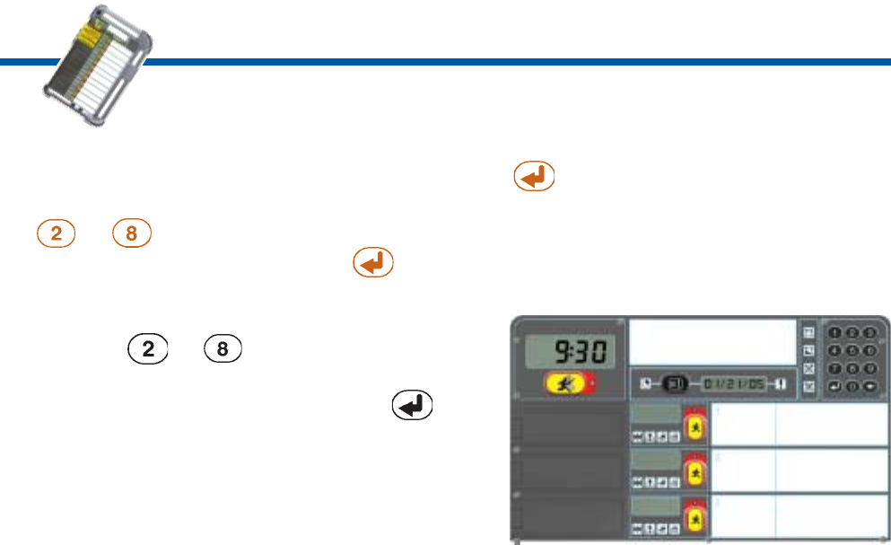
Sleep Mode
When the entry control board is not in use, i.e.
‘Sleep Mode’, the two screens at the top of the
ECB will continuously display the Time and Date
information.
Both the Time and Date can be reset as described
in the Service Section.
In ‘Sleep Mode’, it is also possible to access the
charge condition indicator for the battery pack.
See the following instruction.
Charge Condition Indicator
lWith the ECB in ‘Sleep Mode’ - press and
hold the information button . The date
display changes to show the level of charge
as indicated by a series of ‘dash/dot’ elements.
e.g.
eight elements indicate 100% charge.
four elements indicate 50% charge.
lRelease the information button .
The display will change to show the date
information.
1441USA
1484

Edition B: April 2005 15
The Data Radio Unit
Power Supply
Important Note: Refer to the User Instructions for the DrägerMan Sentinel for instructions on fitting/
replacing the battery of the Sentinel.
The Data Radio Unit is powered from a single 6.5V rechargeable nickel hydride (NiMH) battery.
Continuous operating time is approximately 8 hours between recharge.
Charging the Battery
The Data Radio Module is supplied without the battery charged or fitted. The battery must therefore be
charged before initial use.
Safety Note: The charging unit is not approved to the same intrinsic safety standard as is applied to
the Data Radio Unit. Do Not attempt to charge the battery underground or in an area designated as,
or subject to explosion hazard.
The following charging accessories are available:
lUniversal Power Supply (AC) Pack
lPower Cord for Universal Power Supply (AC) Pack connection.
lMulti-Charger Module with socket for jack plug (four batteries per module).
Refer to the label attached to the Universal Power Supply (AC) to check that the electrical main supply
voltage corresponds to the specified voltage requirement indicated on the label.
Important Note: The temperature of the battery is measured by a thermistor in the battery cell. To
protect the battery, the charging process will stop if the temperature of the battery is below 14oF (5oC)
or exceeds 104oF (40oC).
When the charged battery is connected to the Data Radio Unit, the ‘Green’ LED of the IR Link Unit on
the rear of the Sentinel, momentarily illuminates indicating satisfactory contact.
Optional charging kits are available for use with vehicle charging installations. Contact Dräger for
details.
Edition B: April 2005
16
Charging Procedure – Battery
lConnect the jack plug of the AC Adaptor to the multi-charger module.
lInsert the battery into an available pocket. The associated LED on the panel will illuminate continuous
‘Green’ indicating commencement of main charging.
Important Note: If the LED ‘flashes red’ (‘charge pending’) this indicates,
1. The battery is in a state of very low charge.
Continue charging until main charging starts.
2. The temperature of the battery is below 41oF (5oC) or exceeds 104oF (40oC).
lWhen the ‘Green’ LED begins ‘flashing’ this indicates a fully charged battery pack.
Remove the battery and assemble the battery to the Data Radio Module.
See the Service Section for instructions on fitting and removing the battery.
Note: The battery can remain connected to the charger without any damage to the battery.
Edition B: April 2005 17
In Use
An Entry Control Officer (ECO) is a competent person nominated to control and monitor an Entry
Control Board (ECB) and to direct and instruct all wearers of Breathing Apparatus (SCBA) at an
incident.
A safe and secure entry control point (ECP) for the ECB should be established from which the ECO
is able to effectively control the adopted procedures. At this point the ECB can be mounted to a tripod
to provide positive support and ease of use at an incident.
The operational control procedures adopted should be in line with the requirements defined by the user
or by national legislation in the country of use. In the case of professional users, e.g. Fire Brigades,
these guidelines are in addition to their own guidelines for command and control procedures.
The following instructions cover the basic operational procedures and the In Use functional features of
the DrägerMan PSS® Merlin® Telemetry System.
Pre – Entry Procedure
The Data Radio Unit - SCBA
lHaving put on the SCBA and carried out all
functional checks as described in the User
Instructions for the apparatus, the Wearer
should activate the Sentinel to ‘operational
mode’. The ‘Green’ LED on the front of the
Sentinel flashes at one-second intervals and
the ‘Red’ LED on IR Link cover also flashes.
The wearer is now available for entry to the
risk area.
Note: When the Sentinel is activated to operational mode, this ‘Wakes Up’ the radio of the Data Radio
Unit into ‘stand by mode’ waiting for a signal from the entry control board, i.e. Log On request .
1448USA

Edition B: April 2005
18
The Entry Control Board - Making Contact
lWith the Sentinel activated in ‘operational mode’ the wearer of the SCBA must pass the encoded
‘Tally Key’ to the ECO with the following information written on the tally using a suitable waterproof
marker;
1. The name of the wearer.
2. The cylinder contents pressure – shown on the Sentinel.
If necessary, the ECO can check that the radio identification number on the label of the tally
corresponds to the radio identification number on the label of the data radio module. Using a
suitable waterproof marker, the ECO can then write and record the following remaining data onto
the tally;
3. The actual ‘Time In’ to the risk area – shown on the clock of the Entry Control Board.
Note: In the case of incidents where a possibility of radiation risk may be present, a Dosimeter reading
(prior to entry and after exit) may be recorded on the reverse side of the tally.
lThe ECO fully inserts the ‘Tally Key’ into an available channel slot. The following rapid automatic
activation and transmission sequence starts;
1. The ECB immediately ‘Wakes Up’. A double sharp ‘Bleep’ sounds.
Note: The double sharp ‘Bleep’ sounds only when the first tally is inserted.
2. A sensor in the selected channel reads and verifies the code in the transponder of the tally.
3. The radio in the ECB transmits a signal to the same coded Data Radio Unit requesting
to ‘Log On’ the unit onto the ECB.
4. The Data Radio Unit transmits an acknowledgement signal to the ECB.
5. The ECB receives the ‘Log On’ acknowledgement – the data exchange starts.
6. The initial TTW value transmitted from the Sentinel is added to the actual time shown on
the real time clock to determine the ‘Time of Whistle’ (TOW).
7. The ECB starts the ‘Time Elapsed’ count (minutes).
Note: If the ECB is defaulted to show TTW, the ECO should observe the time to whistle (TTW) reading
of the associated Sentinel display and add this time (minutes) to the ‘Time In’ to establish an estimated
‘Time of Whistle’ (TOW). Using a suitable waterproof marker, the estimated ‘Time of Whistle’ should be
recorded in the rectangular white area on the control board adjacent to the selected channel slot in the
ECB or over the tally area.
Edition B: April 2005 19
Note: An intermittent short ‘flash’ Off of the Red LED signals a low charge condition
of the radio battery. Fit a fully charged battery.
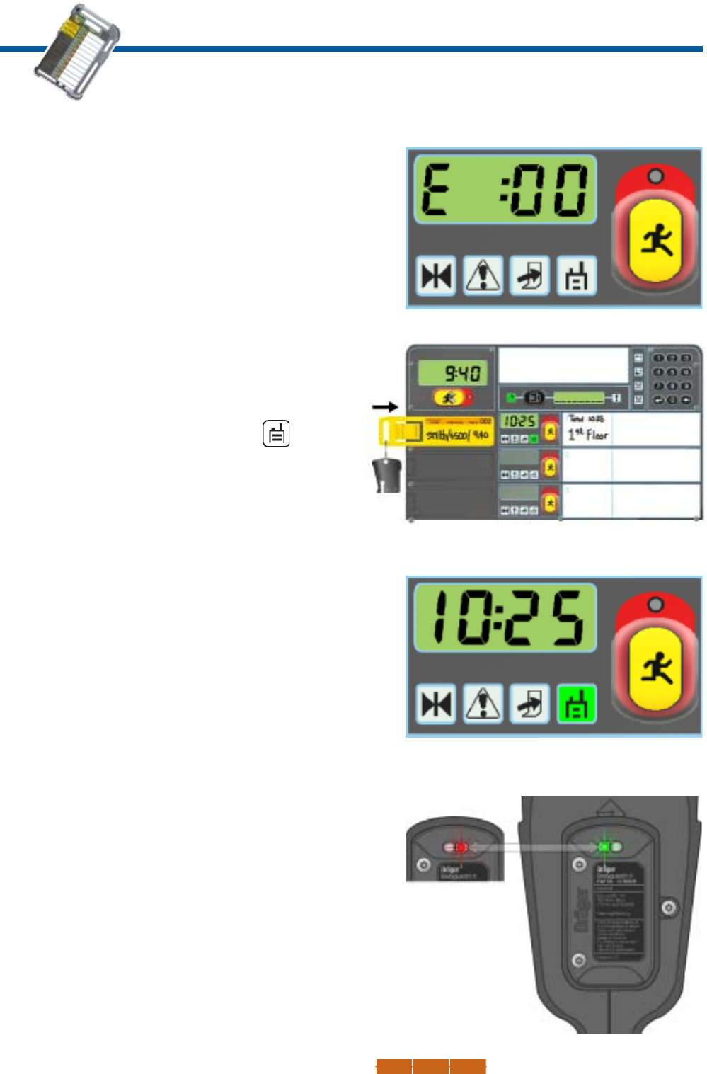
lDuring the ‘Log On ‘ sequence the following
visual changes take place on the ECB and the
Sentinel:
1. The channel screen momentarily displays
the data radio identification number,
followed by the time count display (E :00),
then changes to the default - ‘Time of
Whistle’ (TOW).
Note: The time to whistle (TTW) value is shown in
the display of the Sentinel.
2. The On-Line data radio icon
illuminates ‘Green’ continuously,
confirming a successful radio link with
the Sentinel.
Important Note: If the channel screen momentarily
shows a Fault Code ‘Et’ then changes to E :00
display, the ‘Log On’ has been unsuccessful and
initially indicates a defective transponder in the tally.
Refer to the next section - Making Contact – Manual.
3. The date display changes to show a series
of ‘dash/dot’ elements that provide an
indication of the charge condition of the
batteries.
e.g. eight elements indicate 100%
charge.
4. The ‘Green’ and ‘Red’ LED’s of the IR
Link Unit on the rear of the Sentinel ‘flash’
alternately confirming:
la successful radio link with the ECB - flashing
‘Green’.
la satisfactory charge condition of the Data
Radio Unit battery - flashing ‘Red’.
1502
1449USA
1450
1451
Edition B: April 2005
20
lWhen the data radio code is entered, check again that the displayed code corresponds to the code
shown on the label of the tally, or the label of the data radio module. If incorrect, use the backspace
key to delete the incorrect digit(s) then proceed to input the correct number(s). When the
codes match, press the key. The following visual changes take place on the board and the
Sentinel:
lThis Log On procedure can be repeated to
achieve a Log On of up to a further eleven
wearers (Data Radio Units) to the remaining
channel slots.
lThe wearer is now released for entry to the
risk area.
Making Contact - Manual
An unsuccessful ‘Log On’ identified by an initial momentary display of the fault code ‘Et’ followed by the
display changing to E :00 (time count), indicates a probable defective transponder in the tally. A single
audible ‘Bleep’ alarm is emitted until the manual ‘Log On’ is started. To manually start the activation and
transmission sequence to ‘Log On’ the Data Radio Unit/Sentinel combination to the ECB the following
procedure should be followed.
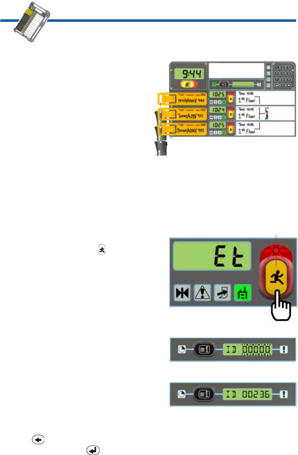
lTo acknowledge the ‘Et’ Fault Code, press
the channel evacuation key . The ‘Red’
LED above the button icon will illuminate and
begin flashing. The main display will change
to show ‘ID 00000’ with the numeric characters
‘flashing’.
lRefer to the label of the tally, or the label of
the data radio module to confirm the data radio
code. Enter the data radio code by pressing
the appropriate numeric keys of the keypad.
The numeric characters will stop ‘flashing’ and
the ID will change from the right as the
numbers are entered.
Note: Commence input of the radio code beginning
with the first whole number – ignore the prefixed
zero(s).
Example Code
1453
1454
1455
1452USA

Edition B: April 2005 21
1. The channel screen displays momentarily the radio identification number and then changes to
‘Time of Whistle’ (TOW).
Note: The time to whistle (TTW) value is shown in the display of the Sentinel.
2. The On-Line radio icon illuminates ‘Green’ continuously, confirming a successful radio
link with the Sentinel. Refer to Important Note.
3. The ‘Green’ and ‘Red’ LED’s of the IR Link Unit on the rear of the Sentinel ‘flash’ intermittently,
confirming a successful radio link with the ECB.
lThe wearer is now released for entry to the risk area.
Important Note: Following the incident and after Log Off, a faulty tally must be reported and replaced
as soon as possible.
Edition B: April 2005
22
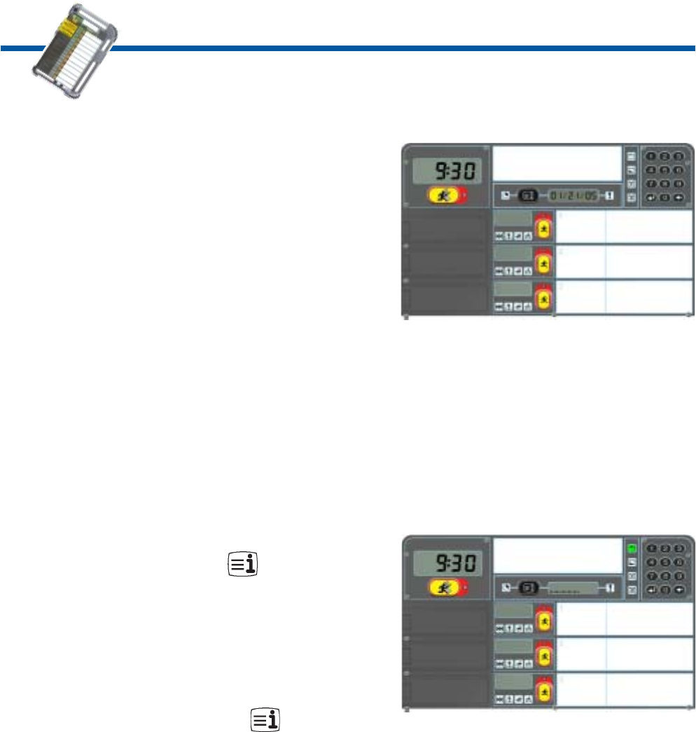
In Use
Monitoring Data – Entry Control Board
Updated data is received every 20 seconds from
each ‘Logged On’ Data Radio Unit and is displayed
on the associated channel screen of the ECB. The
‘Time of Whistle’ information (as shown) is the
standard default data displayed and the clock icon
display illuminates ‘Green’ continuously.
The following additional data is available to the
controller:
lTime to Whistle.
lPressure.
lTemperature of the Sentinel.
lTime Elapsed.
letc. Contact Dräger for more details
By repeatedly pressing the information key, within 10 seconds of each data change, the controller is
able to scroll between the standard default ‘Time of Whistle’ (TOW), and the above data, for all active
channels. After 10 seconds, all the active channel screens will default back to Time of Whistle. A single
sharp audible ‘Bleep’ signal sounds each time the key is pressed.
Note: The clock icon illuminates only when the default time display is shown, i.e. ‘Time of Whistle’,
or ‘Time to Whistle’ data is displayed on the channel screen.’
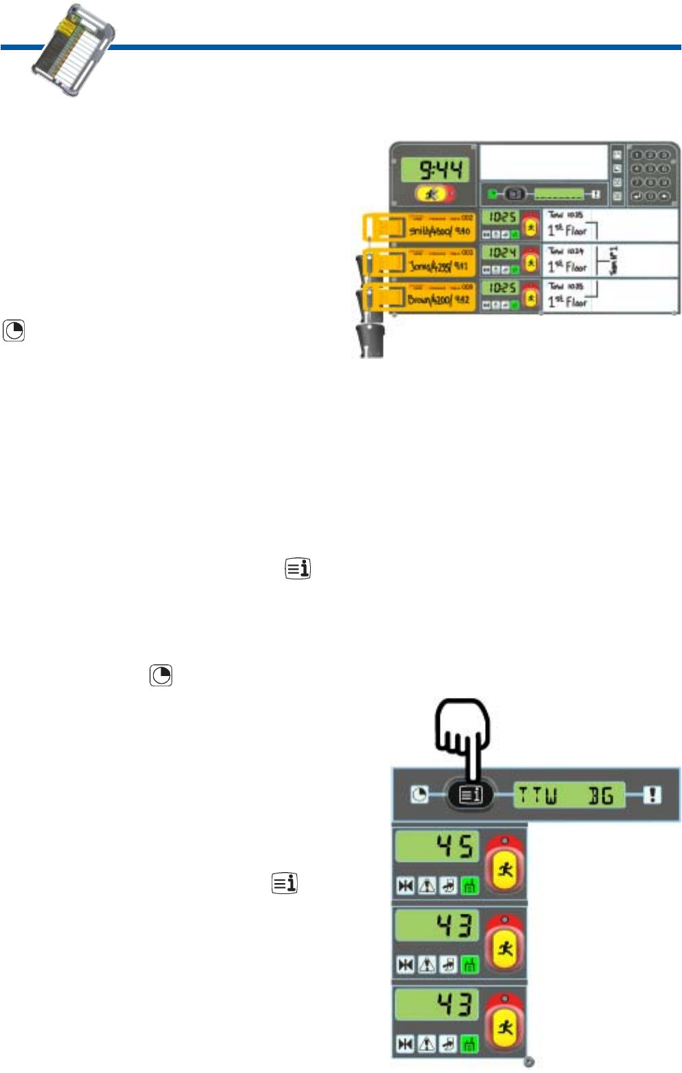
Time to Whistle
lRepeatedly press and release the key
until the information screen shows ‘TTW BG’
(time to whistle of the Sentinel).
All the active channel screens change to show
the actual time to whistle status for each of
the logged on portable units. After 10
seconds, all the active channel screens will
default to Time of Whistle. 1456
1452USA
Edition B: April 2005 23
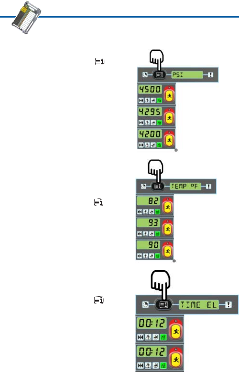
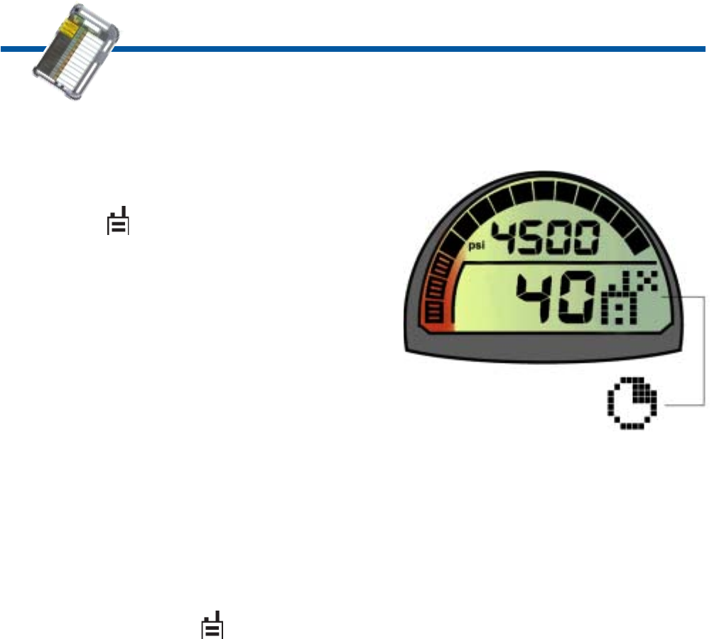
Pressure
lRepeatedly press and release the key
until the information screen shows ‘PSI’
(pressure).
All the active channel screens change to show
the actual pressure status for each of the
logged on Data Radio Unit. After 10 seconds,
all the active channel screens will default to
Time of Whistle.
Temperature
lRepeatedly press and release the key
until the information screen shows ‘TEMP oF ’
(temperature oF of the Sentinel).
All the active channel screens change to show
the temperature status for each of the logged
on Sentinels. After 10 seconds, all the active
channel screens will default to Time to Whistle.
Time Elapsed
lRepeatedly press and release the key
until the information screen shows ‘TIME EL ’
(actual time elapsed since activation of the
Sentinel).
All active channel screens change to show
the actual time elapsed for each of the logged
on Data Radio Units. After 10 seconds, all
the active channel screens will default to Time
of Whistle. 1459
1457USA
1458USA

Edition B: April 2005
24
Whistle Warning Activation
An audible and visual warning signal is available on the ECB that will alert the ECO of the imminent
activation of the whistle warning of a ‘Logged On’ Sentinel.
Unless otherwise requested at the commissioning process, this first alarm default activates 10 minutes
before the activation time of the whistle.
The ECO is also alerted to the actual activation of the whistle warning of the Sentinel.
Both alarms are recognised by a single double ‘Bleep’ and the associated channel display continuously
‘flashing’.
Note: During the commissioning process it is possible to program the first alarm timing to meet customer
requirement.
Edition B: April 2005 25
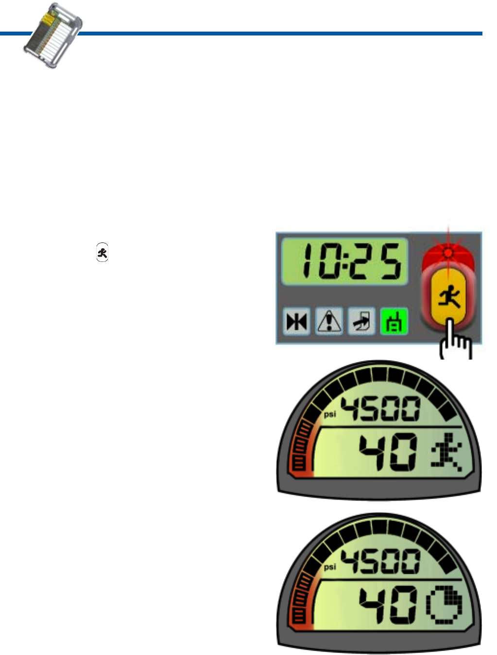
lECO - Press and hold the selected channel
evacuation key until the ‘Red’ LED above
the button illuminates and begins ‘flashing’,
and a double sharp ‘Bleep’ is emitted indicating
the signal is being transmitted. If required
repeat this sequence for any additional units.
lSentinel – The selected unit(s) will emit a
repeating audible ‘Bleep’ alarm and the ‘running
man’ icon will appear in the display of the
Sentinel.
To acknowledge the evacuation request the
wearer must press the RH button of the
Sentinel – a single ‘Bleep’ is emitted.
Immediately release the button and the display
will change to ‘operational mode’.
lECO – On acknowledgement of the
evacuation signal from the wearer, a short ‘trill’
alarm is activated on the ECB. The ‘Red’ LED
above the button stops ‘flashing’ and illuminates
continuously indicating that the signal has been
received and acknowledged by the selected
Sentinel. The ‘Red’ LED will remain illuminated.
In Use - Communication
From ECB to Sentinel
Evacuation Signal - Selective
This procedure allows the ECO to select and signal to a specific logged on Data Radio Unit, or a
designated number of units (team), to evacuate the risk area and return to the control point.
Note: This sequence can be repeated as many times as required until the wearer has returned to the
control point.
1448USA
1461USA
1460
Edition B: April 2005
26
again press the RH button. The display will change
to ‘operational mode’.
lECO – On acknowledgement of the
evacuation signal from each wearer a short
‘trill’ alarm is activated on the ECB. The ‘Red’
LED above the evacuation key of each
acknowledged channel will stop ‘flashing’ and
illuminate continuously indicating that the signal
has been received and acknowledged by the
selected Sentinel.
The ‘Red’ LED to the right of the evacuation
button will remain ‘flashing’ until the
evacuation request has been acknowledged
by all logged on units.
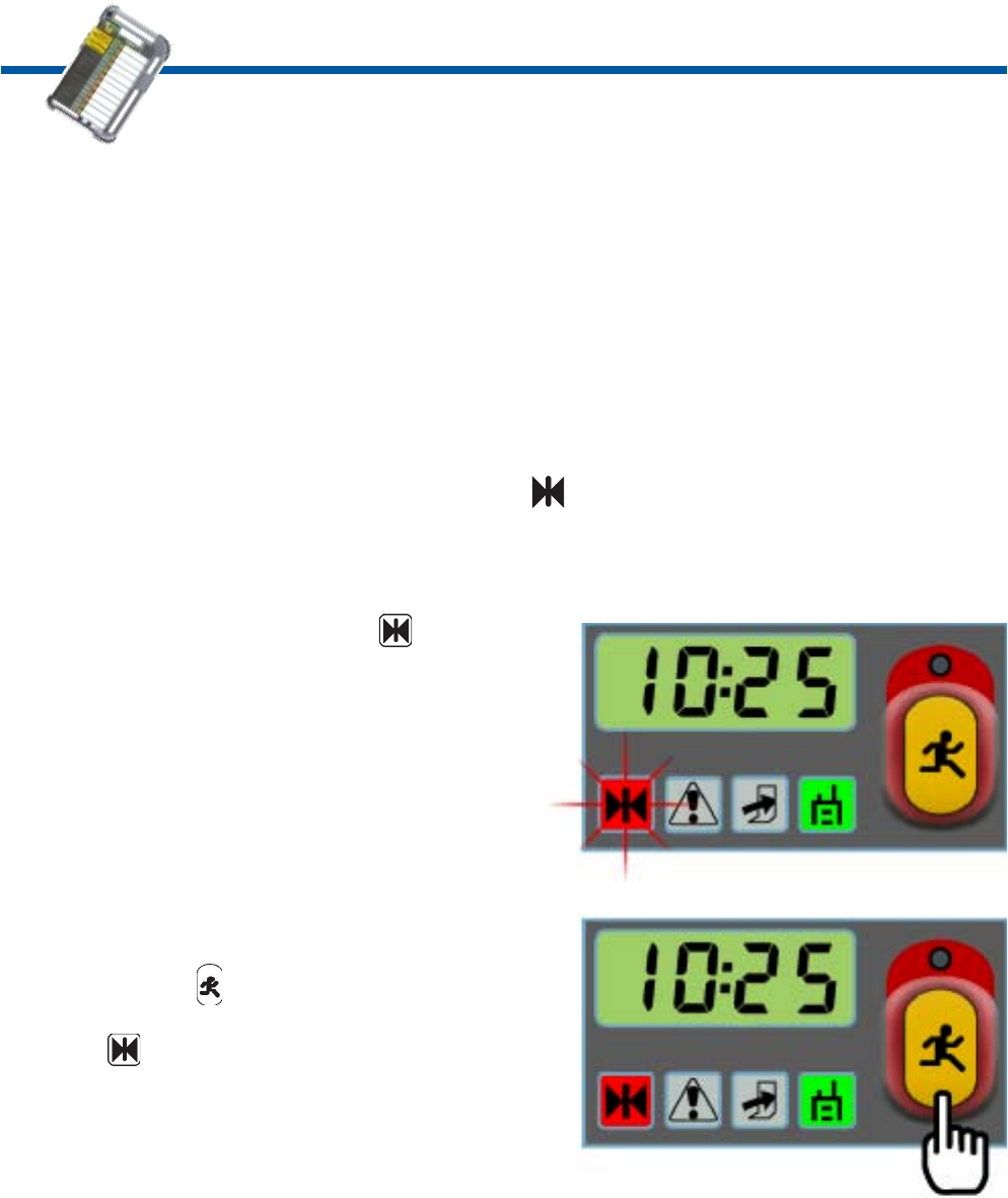
Evacuation Signal – All
This procedure allows the ECO to signal to ‘All’ logged on Data Radio Units to immediately evacuate the
risk area and return to the control point.
lECO - Press and hold the evacuation key
until the ‘Red’ LED above the button
illuminates and begins ‘flashing’, and a double
sharp ‘Bleep’ is emitted. The ‘Red’ LED above
the button of each of the ‘logged on’ units will
also begin ‘flashing’ indicating the signal is
being transmitted.
lSentinel – All units will emit a continuous
audible ‘Bleep’ alarm and the ‘running man’
icon will appear in the display of the Sentinel.
To acknowledge the evacuation request each
wearer must press the RH button of the
Sentinel – a single ‘Bleep’ is emitted –
immediately release the button the display will
change to ‘operational mode’.
Important Note: If the ‘running man’ icon reappears,
1462
1461USA
1448USA
Edition B: April 2005 27
From Sentinel to ECB
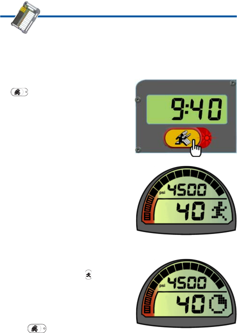
Voluntary Withdrawal Signal
Should the wearer of the breathing apparatus make
a decision to withdraw from an incident, a signal
can be transmitted to the ECB by pressing and
holding the RH button of the Sentinel until the
radio icon is displayed. On observing the
radio icon, the wearer should release the RH button.
The display of the Sentinel will change back to
‘operational mode’.
lECB – The voluntary withdrawal icon of
the associated channel will begin ‘flashing’
(Amber) and an intermittent alarm will sound
indicating that the signal has been received
from the Sentinel.
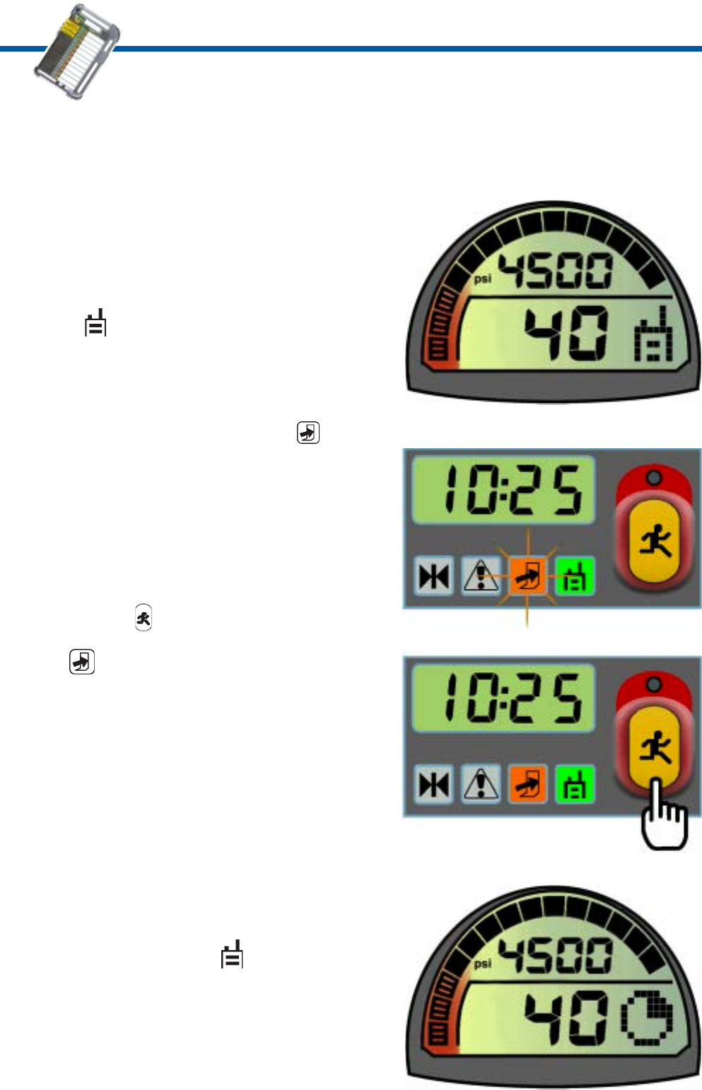
lECO – Having been alerted, and the wearer
identified, the ECO can confirm the alarm by
pressing the button of the appropriate
channel. The sounder alarm stops, the alarm
icon stops ‘flashing’ and illuminates
continuously indicating that the signal has been
received and acknowledged.
lSentinel– On acknowledgement from the ECO
the Sentinel emits a short audible alarm, during
which time the radio icon is displayed.
When the alarm stops the display of the
Sentinel will change back to ‘operational
mode’.
Note: This sequence can be repeated as many times
as required by the wearer.
1464
1463USA
1448USA
Edition B: April 2005
28
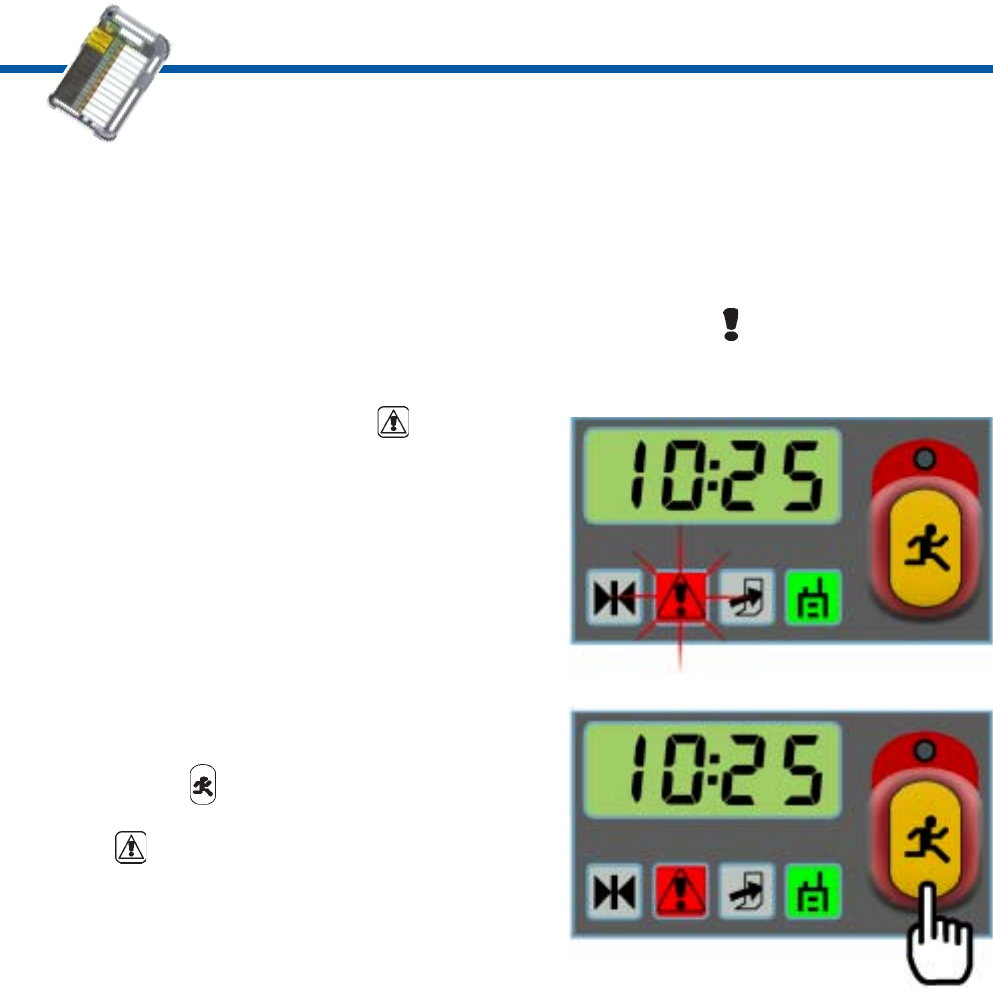
Distress Signal (Automatic – ADSU) - Motion Sensor
Refer also to the User Instructions for the Sentinel.
A motion sensor is incorporated in the Sentinel. If movement is not detected for 23 seconds, the
instrument emits an audible ‘pre-alarm’ to the wearer (not to the ECB). This alarm is automatically
cancelled if movement is detected within a further 8 seconds.
If no movement is detected after the 8 seconds of ‘pre-alarm’ then a higher level ‘main alarm’ is activated.
The screen of the Sentinel displays the motion icon and a signal is transmitted to the ECB.
lECB – The motion alarm icon of the
associated channel will begin ‘flashing’ (Red)
and an intermittent alarm will sound indicating
that the signal has been received from the
Sentinel.
lECO – Having been alerted, and the wearer
identified, the ECO can confirm the alarm by
pressing the button of the appropriate
channel. The sounder alarm stops, the alarm
icon stops ‘flashing’ and illuminates
continuously indicating that the signal has been
received and acknowledged.
lSentinel - on acknowledgement from the ECO, the Sentinel interrupts the ‘main alarm’ with a short
audible tone, during which time the radio icon is displayed. Following the short acknowledgement
tone the Sentinel reverts back to the ‘main alarm’.
Important Note: The ECO can now make a decision as to what action is necessary in line with established
guidelines and control procedures.
lECB - if the ADSU (main alarm) is cancelled at the Sentinel, then the alarm icon at the ECB is
switched ‘Off’ - only if acknowledged.
1465
Edition B: April 2005 29
Distress Signal (Manual) – Panic Button
Should the wearer of the breathing apparatus become distressed and/or require assistance then pressing
the ‘panic button’ of the Sentinel will activate the main audible alarm to the wearer and a signal is
transmitted to the ECB. The screen of the Sentinel displays the panic icon and a signal is transmitted
to the ECB.
lECB – The distress signal icon of the
associated channel will begin ‘flashing’ (Red)
and an intermittent alarm will sound indicating
that the signal has been received from the
Sentinel.
lECO – Having been alerted, and the wearer
identified, the ECO can confirm the alarm by
pressing the button of the appropriate
channel. The sounder alarm stops, the alarm
icon stops ‘flashing’ and illuminates
continuously indicating that the signal has been
received and acknowledged.
lSentinel – The Sentinel will remain in ‘full alarm’
condition until the tally is inserted in the
Sentinel.
lSentinel - on acknowledgement from the ECO, the Sentinel interrupts the ‘main alarm’ with a short
audible tone, during which time the radio icon is displayed. Following the short acknowledgement
tone the Sentinel reverts back to the ‘main alarm’.
Important Note: The ECO can now make a decision as to what action is necessary in line with established
guidelines and control procedures.
lECB - if the ADSU (main alarm) is cancelled at the Sentinel, then the alarm icon at the ECB is
switched ‘Off’ - only if acknowledged.
1466
Edition B: April 2005
30
If there is a loss of radio contact between the radio
of the ECB and the Data Radio Unit then the On-
line radio icon of the affected channel of the
ECB will begin to flash. The ‘Green’ LED at the
rear of the associated Sentinel will stop flashing
and the ‘lost’ communication icon will be displayed
on the Sentinel accompanied by an audible ‘bleep’
tone. During the communication failure the ‘lost’
communication icon will be displayed alternating
with the clock (operation) icon - as shown. If at
any time radio contact is re-established then the
On-line radio icon of the ECB will illuminate ‘Green’
continuously and the ‘Green’ LED of the Sentinel
will begin flashing and the ‘lost’ communication
icon will be cancelled. The associated channel
screen data will be updated at the next data signal
transmission from the Sentinel.
Loss of Radio Contact (ECB to PU)
1906
During loss of radio contact the following should be noted:
lThe On-line radio icon of the affected channel of the ECB will continue to flash.
lThe ‘Green’ LED at the rear of the associated Bodyguard will stop flashing and the ‘lost’
communication icon will be displayed.
lThe associated channel screen will no longer show the result of the dynamic data transmitted from
the Sentinel. Data will change against real time as follows;
TTW - If ECB is programmed at Time to Whistle (TTW) the data screen time will count down at
one-minute intervals from the time shown at the point of loss of radio contact.
TOW - If ECB is programmed at Time of Whistle (TOW) the data screen time will remain at the time
shown at the point of loss of radio contact.
Important Safety Note: In the case of possible permanent loss of radio contact then the ECO and the
wearer of the Sentinel must take appropriate actions in line with established user guidelines and control
procedures.

Edition B: April 2005 31
After Use
All wearers of breathing apparatus that are Logged On to an ECB must return to the Entry Control Point
(ECP) to ensure that the Log Off procedures are followed. The procedures must be carried out under
the supervision and control of the Entry Control Officer (ECO).
Log Off Procedure
lThe compressed air breathing apparatus is to be shut down by the wearer as described in the After
Use section of the User Instructions supplied with the equipment, i.e. remove facepiece, close
cylinder valve, vent the system of pressure. The display of the Sentinel will show ‘0’ PSI and ‘0’
TTW. The ECB will emit two short audible ‘Bleeps’ and the associated channel screen of the ECB
will ‘flash’ the Time of Whistle data that will now correspond to the time shown on the Time Clock.
Note: The Sentinel will remain in ‘operating mode’ until it is switched ‘Off’ (deactivated).
lAt the ECB the ECO will identify the wearer then remove the tally from the associated channel and
hand it over to the wearer. On removing the tally, and after up to 20 seconds the channel screen
will begin to alternate between displaying the data radio identification number and the Time of
Whistle data.
lThe wearer should switch ‘Off’ the Sentinel. A Log Off signal will be transmitted from the Data
Radio Unit to the ECB. After up to 20 seconds the channel screen will switch ‘Off’ and the
associated Data Radio Unit will return to ‘Sleep Mode’ - ensure all IR link LED’s are ‘Off’.
lRepeat the above procedure for all Logged On units. The ECB will not return to ‘Sleep Mode’ until
all other Data Radio Units have been Logged Off.
Important Note: If during an incident a permanent breakdown in communication has occurred between
the ECB and a ‘Logged On’ Data Radio Unit, it will be necessary to initiate a Force Log Off procedure.
See section ‘Forced Log Off Procedure’.
Edition B: April 2005
32
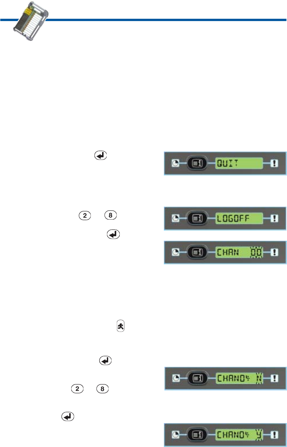
lRemove the tally – press the key the
main screen changes to the selected channel,
e.g. ‘CHAN04 N’ with the ‘No’ symbol
‘flashing’. Using the or keys of
the keypad toggle between the ‘Yes’ and ‘No’
symbol. When ‘CHAN04 Y’ is displayed
again press the key, the display will
change to ‘LOGOFF’. Repeat the procedure
for any further Data Radio Units requiring a
Forced Log Off.
lCheck the Channel number to be Logged Off and then enter the number by either:
1. pressing the appropriate numeric keys of the keypad. The numeric characters will stop
‘flashing’ and will change from the right as the number(s) is entered.
or
2. pressing the evacuation button of the appropriate channel. The channel number will be
entered automatically on the display.
lPress and then release the key of the
keypad. The display changes to show ‘QUIT’
status.
Note: A single sharp audible ‘Bleep’ signal sounds
each time a key is pressed.
lRepeatedly press the or keys of
the keypad to scroll the display until ‘LOGOFF’
is displayed and then press the key.
The main display will change to show ‘CHAN
00’ with the numeric characters ‘flashing’.
Forced Log Off Procedure
A breakdown in communication between the ECB and a Logged On Data Radio Unit will cause the
illuminated ‘Green’ On-Line radio icon of the associated channel to begin to ‘flash’. The channel screen
will display the last value transmitted before failure of the signal. This may only be a temporary
communication failure due to the wearer becoming out of range of the ECB. When the date radio unit
comes back in range, the On-Line radio icon will return to illuminate continuously, confirming that the
radio link has been re-established. If however the breakdown in communication is permanent, it will be
necessary on the return of the wearer to the Entry Control Point for the ECO to initiate the following Force
Log Off procedure. This procedure is necessary to return the ECB to ‘Sleep Mode’.
1469
1468
1472
1471
1467
Edition B: April 2005 33
Important Note: If the tally has not been removed, and the key has been pressed, the display will
not change but will remain at ‘CHAN04 N’ with the ‘No’ symbol ‘flashing’. Remove the tally then using
the or keys of the keypad toggle between the ‘Yes’ and ‘No’ symbol until ‘CHAN04 Y’ is
displayed. When displayed press the key, the display will change to ‘LOGOFF’.
lWhen the display shows ‘LOGOFF’, repeatedly
press the or keys of the keypad to
scroll the display until the ‘QUIT’ status is
displayed. When displayed - press the
key – the display will change to show the current
date information. If all other Data Radio Units
have been Logged Off the board is now
returned to ‘Sleep Mode’.
lThe tally should be passed to the wearer of
the associated Data Radio Unit. The wearer
should refit the tally to the Sentinel to switch
‘Off’ the instrument.
1441USA
Important Note: Following the incident and after Log Off, the fault must be reported.
Edition B: April 2005
34
Service Information
Setting Time Display
lWith the ECB in ‘Sleep Mode’ - press and then release the key of the key pad. The ‘clock’
display and the ‘date/information’ display will illuminate. The date display changes to show ‘QUIT’
status and will remain illuminated for a preset period.
Note: A single sharp audible ‘Bleep’ signal sounds each time a key is pressed.
lRepeatedly press the or keys of the key pad to scroll the display until ‘SET TIME’ is
displayed, then press the key. The current time is shown in the display with the first (hour)
character ‘flashing’.
lEnter the required numeric value by pressing the appropriate key of the key pad - the next character
will begin ‘flashing’. Repeat the procedure until all the required characters are set.
Note: If an error is made, press the ‘backspace’ key to return to the previous digit location and enter
the correct number.
lWhen the required time is displayed - press the key to confirm the selection. Repeatedly
press the or keys to scroll the display until ‘QUIT’ status is displayed (or if required go
to ‘SET DATE’). When ‘QUIT’ status is displayed press the key. The ‘clock’ display will
change to show the updated time information.
Setting Date Display
lWith the ECB in ‘Sleep Mode’ - press and then release the key of the key pad. The ‘clock’
display and the ‘date/information’ display will illuminate. The date display changes to show ‘QUIT’
status and will remain illuminated for a preset period.
Note: A single sharp audible ‘Bleep’ signal sounds each time a key is pressed.
lRepeatedly press the or keys of the key pad to scroll the display until ‘SET DATE’ is
displayed, then press the key. The current date is shown in display with the first character
‘flashing’.
lEnter the required numeric value by pressing the appropriate key of the keypad - the next character
will begin ‘flashing’. Repeat the procedure until all the required characters are set.
1. Note: In the case of single figure day or month then first press key.
2. Note: If an error is made, press the ‘backspace’ key to return to the previous digit location and
then enter the correct number.
Edition B: April 2005 35
lWhen the required date is displayed - press the key to confirm the selection. Repeatedly
press the or keys to scroll the display until ‘QUIT’ status is displayed (or if required go
to ‘SET TIME’). When ‘QUIT’ status is displayed press the key. The display will change
to show the updated date information.
Display Test - ECB
This test allows the user to check that all LCD’s, LED’s, sounder, backlight and keys are functioning.
lWith the ECB in ‘Sleep Mode’ - press and then release the key of the key pad. The date
display will change to show ‘QUIT’ status.
lRepeatedly press the or keys of the key pad to scroll the display until ‘TEST’ is displayed,
then press the key. All LCD’s, LED’s, and the backlight will begin to ‘flash’.
lVisually check that all features are functioning. Press and release each key (not the key). A
single sharp ‘Bleep’ signal should sound each time a key is pressed. Record any features that are
faulty then contact Dräger Service.
Note:
Pressing the key at any time will return the date screen to show ‘TEST’. The Display Test
will however automatically default to ‘Sleep Mode’ after two minutes.
lRepeatedly press the or keys of the key pad to scroll the display until ‘QUIT’ is displayed,
then press the key. The display will change to show the date - ‘Sleep Mode’.
Edition B: April 2005
36
Note: Commence input of the data radio code beginning with the first whole number – ignore the prefixed
zero(s).
lWhen the data radio code is entered, check again that the displayed code corresponds to the code
shown on the label of the Data Radio Unit. If an error is found, use the backspace key to
delete the incorrect digit(s) then proceed to input the correct number(s).
lWhen the codes match, select and insert fully a new tally into the first channel (Channel 1) of the
ECB then press the key.
Example Code
Encoding a Tally
The following instruction details the procedure for encoding the transponder of a new tally with both the
identification code of the associated Data Radio Unit and the unique user identity code, (e.g. Fire
Brigade Identity Code, or a User Code). This procedure can only be successfully activated with the tally
inserted in the first channel (Channel 1) of the ECB.
The unique user identity code is already encoded into the associated ECB. The final action of entering
and encoding the identification code of the Data Radio Unit will signal the ECB to also encode the user
identity code to the tally.
lWith the board in ‘Sleep Mode’ - press and then release the key of the key pad. The ‘clock’
display and the ‘date/information’ display will illuminate. The date display changes to show ‘QUIT’
status and will remain illuminated for a preset period.
Note: A single sharp audible ‘Bleep’ signal sounds each time a key is pressed.
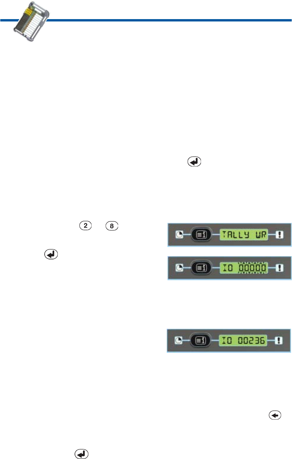
lRepeatedly press the or keys of
the key pad to scroll the display until ‘TALLY
WR’ is displayed (i.e. write to tally) and then
press the key. The display will change
to show ‘ID 00000’ with the numeric characters
‘flashing’.
lCheck the radio identification number on the
label of the Data Radio Unit then enter the
radio code by pressing the appropriate
numeric keys of the key pad. The numeric
characters will stop ‘flashing’ and the ID will
change from the right as the numbers are
entered.
See example.
1473
1474
1475
Edition B: April 2005 37
Note: If the tally is not inserted into the first channel within 18 seconds, the ECB will return to ‘sleep mode’.
lOn pressing the key the radio identification number is encoded to the transponder of the tally and
at the same time, the unique user identity code is automatically encoded to the transponder from
the ECB. The main screen changes to ‘TALLY WR’.
Important Note: The identification codes can only be encoded to the tally when the tally is inserted into
Channel 1. It is not possible to carry out this procedure with no tally inserted or with the tally inserted
in any other channel. If the enter key is pressed, with no tally inserted in Channel 1, the display
will show ‘TALLY NO’. Press the enter key the display will change to ‘TALLY WR’. Proceed to
correctly repeat the encoding procedure.
lRemove the encoded tally – the main screen remains at ‘TALLY WR’. If required, proceed to
encode another tally, or - repeatedly press the or keys to scroll the display until the
‘QUIT’ status is displayed. When displayed - press the key. The display will change to show
the current date information. The board is now returned to ‘Sleep Mode’.
lUsing a suitable permanent marker, write and add the data radio identification code and the unique
user identity code number in the spaces provided on the label of the new tally. Ensure the coded
tally is allocated and stored with the associated Data Radio Unit/Sentinel combination.
Edition B: April 2005
38
Removing/Fitting Battery Packs
Entry Control Board
Tools Required
3mm AF Hexagon Socket Key
lUnscrew and remove the ten (10) socket set
screws from around the battery cover. When
all screws have been removed, use fingers in
the slots at the top and bottom of the back
cover of the ECB to lift and remove the battery
cover.
lCarefully lift the first battery from the compartment until the connection plug in the side of the
battery is accessible. Do Not pull on the cable.
lPress and hold the release tab of the plug and remove the plug from the battery connector.
lFit fully charged battery. Insert the connection plug into the connection socket of the battery.
Carefully insert the battery into the battery compartment.
lRepeat with the second battery.
lAlign and locate the battery cover and using the ten (10) socket set screws, secure the cover to the
ECB. Do Not overtighten the socket set screws (0.37 to 0.44ft lbs).
Data Radio Unit
Tools Required
Release Key 3351827
lTo remove the battery - insert the pins of the release key into the two holes in the base of the Data
Radio Unit. Press the key into the module until the locking mechanism is released and the battery
retracts (approx. 0.2in). Remove the key and then slide and remove the battery.
Note: Before fitting the charged battery check that the O ring seal of the boss is in position and not
damaged and that the dovetail guide of the battery and the radio module are clean.
lTo fit the battery, locate the battery to the dovetail guide of the data radio pack then slide the battery
pack along the guide until a positive audible ‘click’ is heard. The ‘Green’ LED of the IR Link Unit
on the rear of the Sentinel momentarily illuminates indicating satisfactory contact. Correct retention
is indicated when the ‘Red’ indicators are visible in the two release key holes in the base of the Data
Radio Unit. To further ensure positive retention, grip the battery and attempt to remove - there must
be no movement.
1544 1492

Edition B: April 2005 39
Care
The Entry Control Board and the Data Radio Unit do not require any routine attention by the user.
Do Not immerse the Entry Control Board or the Data Radio Unit in cleaning fluids. When considered
necessary by the user, remove dirt and contaminants by carefully cleaning using a clean lint free cloth
dampened in a mild soap solution then apply a proprietary antistatic cleaning agent to a clean lint free
cloth and clean the surface of the units, especially the clear fascia panel of the ECB.
If necessary, the clear fascia panel can be removed for cleaning of the inner surface of the fascia, the
electronic membrane and the channel slots of the main board. Do Not use abrasive cleaning agents on
the fascia or the electronic membrane.
Apply a proprietary antistatic cleaning agent to a clean lint free cloth and carefully clean the electronic
membrane and the surface of the inner surface of the fascia, then reassemble the fascia to the main
board. Do Not overtighten the screws (0.3ft lbs maximum).
Ensure that the dovetail guide of the battery and the Data Radio Unit are clean and not damaged and that
the antenna is secure.
Safety Note: Do Not use organic solvents, such as Acetone, Alcohol, White Spirit, Trichloroethylene or
similar or abrasive cleaning agents.
Edition B: April 2005
40
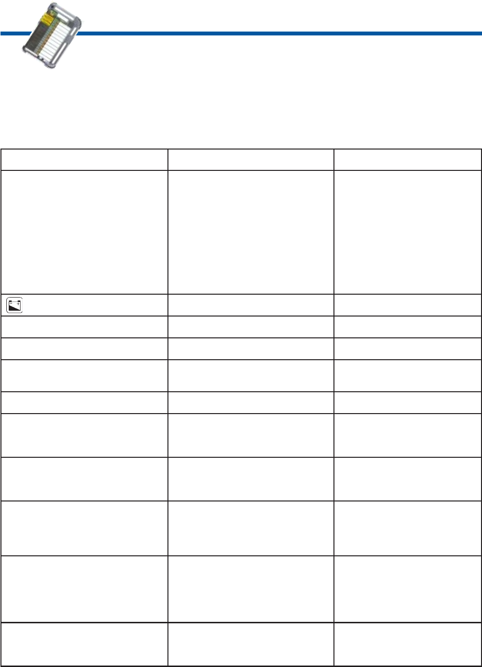
stluaFsesuaCsnoituloS
:edoctluafyalpsidretcarahc8
lRREKLC
lRREOIDR
lRREHSLF
lRREYEK
lRRETSYS
lRREHC
lPKCBWOL
lNWODTUHS
gnolootnwoddlehyeK
degrahcsidyrettabpukcaB
ttabwolevissecxEyrenoitidnoc
devomerseirettabhtoB
ecivreSregärDtcatnoC
ecivreSregärDtcatnoC
ecivreSregärDtcatnoC
yekesaeleR
ecivreSregärDtcatnoC
ecivreSregärDtcatnoC
sruoh42rofegrahC
sruoh42rofegrahC
seirettabdegrahctiF
mrala/rebmagnihsalFseirettabwoLseirettabegrahC
tcerrocniyalpsidkcolcemiTgnittestcerrocnIsnoitcurtsnIresUepsateseR
tcerrocniyalpsidkcolcetaDgnittestcerrocnIsnoitcurtsnIresUepsateseR
etadro/dnaemitteserotelbanUnoitcnuflamdapyeK
eruliafyalpsiD
ecivreSregärDtcatnoC
ecivreSregärDtcatnoC
'gnihsalf'tonnoloc-kcolclatigiDeruliafyalpsiDecivreSregärDtcatnoC
edoMpeelS etadro/dnaemitoN-
.deyalpsid
degrahcsidrodevomerseirettabniaM degrahcsidyrettabpukcaBsruoh42rofegrahC
edoMpeelS -etadro/dnaemitoN
degrahcseirettabniaM.deyalpsid
eruliaftiucriCecivreSregärDtcatnoC
yllatdaertonnaCeruliafrednopsnarT
)BCE(eruliafrednopsnarT
eruliaftengaM
)BCE(eruliafhctiwsdeeR
yllatecalpeR
ecivreSregärDtcatnoC
yllatecalpeR
ecivreSregärDtcatnoC
yllatotetirwtonnaClennahcgnorwnidetresniyllaT
detresnitonyllaT
eruliafrednopsnarT
eruliaftengaM
)BCE(eruliafhctiwsdeeR
1lennahcotniyllattresnI
1lennahcotniyllattresnI
yllatecalpeR
yllatecalpeR
ecivreSregärDtcatnoC
neercslennahcnoyalpsidoN
yllatfonoitresnigniwollof
eruliaftengaM
)BCE(eruliafhctiwsdeeR
eruliaftiucriC
yllatecalpeR
ecivreSregärDtcatnoC
ecivreSregärDtcatnoC
Faults - Causes - Solutions
Entry Control Board
Edition B: April 2005 41
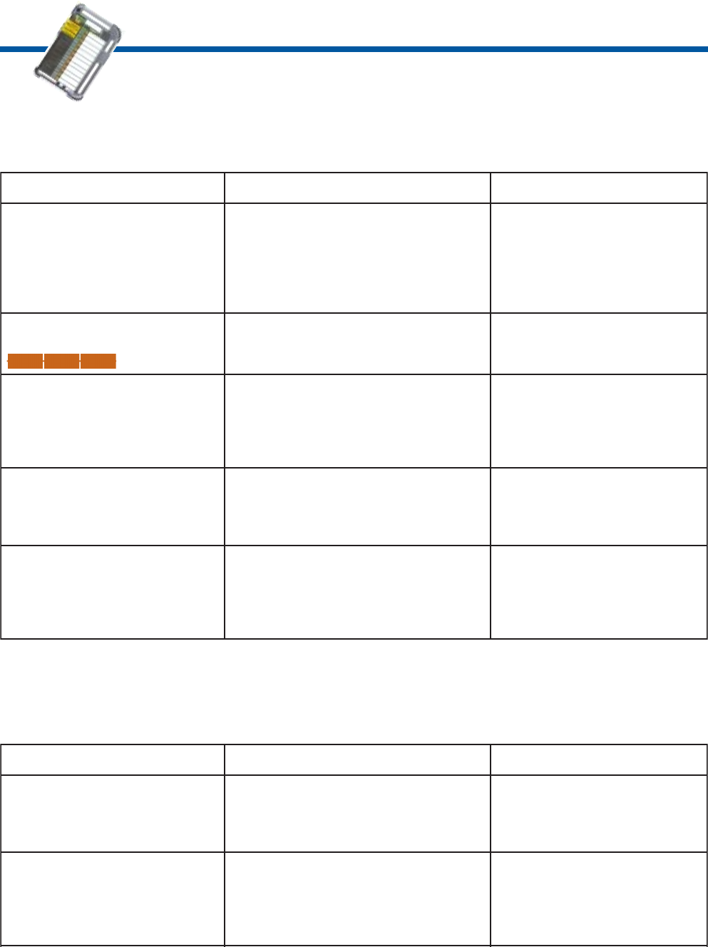
stluaFsesuaCsnoituloS
tonseodknilRIfoDELneerG
noetanimulliyliratnemom
oidarotyrettabfonoitcennoc
degrahcsidyrettaB
oidar/yrettabnoslanimretytriD
oidarotdetcennoctonknilRI
degamadknilRI
oidarytluaF
yrettabegrahC
slanimretnaelC
sevisarbaesutoNoD
knilRItcennoC
knilRIecalpeR
oidarecalpeR
ehtfoffO'hsalf'trohstnettimretnI
DEL'deR'
yrettabwoLyrettabegrahC
egrahctonlliwyrettaByrettabnoslanimretegrahcytriD
egrahcsidpeeD
yrettabtnepS
slanimretnaelC
sevisarbaesutoNoD
42fomuminimarofegrahC
kcehcer-sruoh
wenhtiwecalpeR
oidarotelbmessatonlliwyrettaBsediugliatevodytriD
sediugliatevoddegamaD
demmajsnipgnikcoL
oidardnayrettabnaelC
degamadecalperdnatcepsnI
meti
yekesaelergnisunoitcakcehC
kcabgnirpstonlliwyrettaB
esalerehtfonoitresnino)hcated(
yek
.yekesaelerno)s(nipnekorB
sediugliatevodytriD
msinahcemgnikcoldegamad/ytriD
yekwenesU
llupdnayekesaelerehttresnI
yllaunamyawayrettab
oidardnayrettabnaelC
ecivreSregärDtcatnoC
Data Radio Unit
Entry Control Board and Data Radio Unit
In the event of faults occurring that the user is unable to remedy, contact Dräger Service.
stluaFsesuaCsnoituloS
dnaBCEneewtebtcatnocfossoL
tinuoidaratad
).ctegnidliub(noitacoL
degrahcsidseirettaB
BCE-eruliafoidaR
tinuoidaratad-eruliafoidaR
tinuretaeperredisnoC
seirettabegrahC
ecivreSregärDtcatnoC
oidarecalpeR
nogolotelbanUyllatgnorW
gniruddeyalpsidsawedoctE(yllatytluaF
.)nogolottpmetta
yllattcerrocehttceleS
oidarehtotgnidnopserroc
niagayrT
nogollaunammrofreP
yllatwenaedocnE

Edition B: April 2005
42
Technical Data
Environmental
Operating Temperature
Portable Radio Unit -220F to +1670F
Entry Control Board +50F to +1310F
Portable Radio Unit
Dimensions
Radio (excluding antenna)
Height (inches) 5.16
Width (inches) 3.03
Depth (inches) 2.16
Antenna
Length (inches) 2.36
Diameter (inches) 0.55
Battery
Height (inches) 3.74
Width (inches) 2.83
Depth (inches) 0.67
Tally
Length (inches) 5.71
Width (inches) 1.50
Depth (inches) 0.16
Weights
Radio (including battery) lbs 1.2
Battery lbs 0.4
IR Interface lbs 0.18
Tally lbs 0.05
Battery Details
Battery Type
6.5V NiMH (nickel hydride) battery pack, re-
chargeable.
Battery Life 8 hours min.
Charged Temperature Range 41oF to+104oF
Certification
EN137
For use with all Dräger SCBA
Entry Control Board
Dimensions
Entry Control Board
Height (inches) 30.71
Width (inches) 19.50
Depth (inches) 2.36
Battery
Height (inches) 5.55
Width (inches) 3.15
Depth (inches) 1.53
Weight
Entry Control Board (including batteries) 18.8lbs
Battery Pack 1.1lbs Single Pack (2 per ECB)
Battery Details
Battery Type
7.2V NiMH rechargeable battery pack.
NOT Ex APPROVED
Battery Life 8 hours min.
Charging temp. range 32oF-113oF
Telemetry
Range 1000ft (nominal)
Frequency 450-470 MHz

Edition B: April 2005 43
Order List
The System
Entry Control Board 450-470MHz 3354270
Sentinel Telemetry Upgrade Kit 450-470MHz 3354328
Repeater Unit 450-470MHz 335xxxxx
Replacement Batteries
ECB
7.2V Rechargeable NiMH Battery 335xxxxx
Radio
6.5V Rechargeable NiMH Battery 335xxxxx
Requirements for Operation
Universal Power Supply Unit 3351804
Power Supply Cord - USA 3351807
Charging Adaptor Kit - ECB 3351819
Radio Battery - Multi Charger Module (up to four batteries) 3351815
Radio Battery Release Key (Kit of 4) 3351902
Motor Vehicle Charging Kit - ECB 3351810
Motor Vehicle Charging Kit - (Quick Release) ECB 3354349
Motor Vehicle Charging Kit - Portable Radio Unit 3351681
Accessories
Tripod for ECB 3351802
ECB Support Bracket for Tripod 3351803
Protective Cover – ECB 3351812
Pouch for Data Radio Unit 3351811
Blank Tallies (Pack of 12) 3351828
Chinagraph Pencils (Pack of 12) 3351237
Software for Datalogging (MS-DOS) 335xxxxx
Telemetry Datalink Cable 3351898

Edition B: April 2005
44