Draeger Safety 005 Electronic Monitoring Unit User Manual users manual
Draeger Safety Ltd Electronic Monitoring Unit users manual
users manual
User Instruction
PSS® 7000 SerieS
SeLF-CONTAiNeD BreATHiNG APPArATUS wiTH SeNTiNeL 7000
3356233 : 05 Edition : October 2008 : Subject to Modication (A3-D-P) Page of 4
i
For Your Safety
General safety information for the Dräger PSS® 7000 Series of self-contained breathing
apparatus (SCBA):
Use of this apparatus requires relevant equipment training; observance of this user
instruction (UI); and compliance with national regulations, laws and standards
governing the use of respiratory apparatus.
Use of this apparatus must be only for the purpose specied in this UI, or as conrmed
in writing by Dräger.
Only trained and competent personnel should inspect and service the apparatus at
specied intervals. Records of inspections and servicing are to be maintained in line
with NFPA 1852 – Standard on Selection, Care, and Maintenance of Open-Circuit
Self-Contained Breathing Apparatus.
Use of the apparatus should be consistent with NFPA 1500 – Standard on Fire
Department Occupational Safety and Health Program.
The automatic alarm function of the Sentinel 7000 detects movement of the wearer
and movement or vibration to which the wearer may be subjected.
Do not use any form of chemical marking or paint on the equipment.
Dräger recommend that a service contract be obtained from your Dräger branch or
agent.
Contact Dräger for details of service contracts and training courses.
Use only original Dräger spare parts and test equipment for service, repair and
maintenance.
Notify Dräger if there is component fault or failure.
All approved respiratory equipment shall be selected, tted, used, and maintained
in accordance with Mine Safety and Health Administration (MSHA), Occupational
Safety and Health Administration (OSHA), and other applicable regulations.
Denitions of Alert Icons
The following alert icons are used throughout this document to provide and highlight
areas of the associated text that require a greater awareness by the user. A denition of
the meaning of each icon is as follows:
This icon indicates additional information on how to avoid inconveniences
when carrying out the instructions described.
This icon indicates a potentially hazardous situation which, if not avoided,
could result in physical injury to the user, or damage to the product. It
may also highlight an alert against unsafe practices.
This icon indicates a potentially hazardous situation which, if not avoided,
could result in death or serious injury to the user.
This icon indicates an imminently hazardous situation which, if not avoided,
could result in death or serious injury to the user.
Warranty and Liability Statements
Terms and conditions of warranty for the Dräger PSS® 7000 Series of SCBA and
associated accessories can be found in the original Dräger invoice document, or can be
obtained from Dräger on request.
The Dräger guarantee is void if the original sealing caps on the apparatus are tampered
with, removed or broken
Responsibility for the reliable function of the apparatus transfers to the owner or operator
when it is serviced or repaired by personnel not authorised by Dräger, or when it is used
in a manner not conforming to its intended use.
This device has been tested and complies with the FCC rules. Changes
or modications not expressly approved by the manufacturer will void your
authority to operate this product.
Technical Data
High-Pressure Connections
The following SCBA high-pressure (HP) connections are available for compressed air
cylinders:
2216 psi connection to CGA 346
4500 psi connection to CGA 347
Quick-connect cylinder coupling (2216 psi or 4500 psi).
Power Supplies
Main battery – 7.5 V
Back-up battery – 3 V
Head-up display battery – 3 V.
RIC UAC Connection
2216 psi or 4500 psi male, quick-release coupling with pressure relief valve (PRV).
LDR to Face mask Connection
Dräger push-in connector.
Pressure and Flow Details
Medium pressure – 87 psi to 130 psi
Air ow – In excess of 1000 litres/minute
Air ow at 290 psi – In excess of 500 litres/minute.
EOST Alarms
Activation commencement range (mechanical and electronic):
2216 psi cylinder – 600 psi to 510 psi
4500 psi cylinder – 1215 psi to 1035 psi.
General Information
Batteries
Danger of explosion. Do not change the batteries in an explosive or
ammable atmosphere.
Do not dispose of batteries in a re. Batteries must be disposed of in
line with local regulations.
Do not attempt to recharge any non-rechargeable battery.
Battery information:
Main battery – 7.5 V (5 x 1.5 V AA alkaline batteries)
Back-up battery – 3 V (CR123 lithium battery)
HUD battery – 3 V (CR123 lithium battery).
Use only the following approved battery types:
Duracell MN1500 (1.5 V)
Energizer LR6 (1.5 V)
Panasonic CR123AL/1BP (3 V).
Batteries are supplied with the equipment but are not tted. Dräger
recommend that the batteries be removed when the system is not used
for long periods as a small amount of discharge still occurs. The normal
operating life of the batteries is dependent on usage time, frequency of
alarms, backlight illumination and ambient temperature.
The back-up battery will only supply power when the main battery is
disconnected or discharged. When this occurs, the back-up battery will
only supply power for HUD functions.
Preparation for Use
Equipment congurations for non-CBRN use are detailed in a NIOSH Approval Table
(refer to instruction no. 3356261). Congurations for CBRN use are detailed later in
this instruction (refer to CBRN Use).
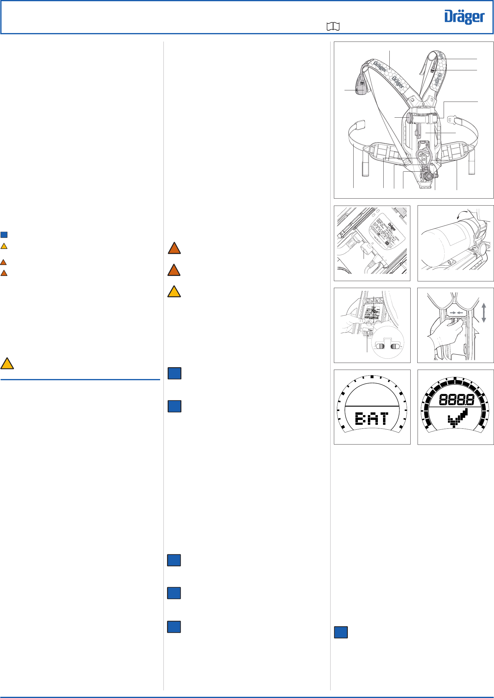
Installing the Back-Up Battery
Orientate the SCBA to access the battery compartment.
Unscrew and remove the battery cap (1, Fig 2), using a suitable coin.
Insert the battery, +ve terminal end rst, into the battery compartment.
Ret and secure the battery cap. Do not overtighten.
Installing the Main Battery
Orientate the SCBA to access the pressure module (1, Fig 3).
Inspect the terminals on the battery and pressure module, and the sealing rim
around the battery terminals (all must be clean and undamaged).
Locate the two slots in the top of the battery pack (2) on the tabs in the battery
housing.
Firmly press the battery into position until an audible click is heard, to indicate a
secure attachment. The Sentinel 7000 will emit a single tone and will commence
the self-check sequence (refer to Sentinel 7000 Self Check).
Press and hold the RH and LH buttons of the user interface until the display clears,
then immediately release the buttons.
A battery check is performed during the self-check sequence. If the
battery voltage is below a preset voltage the backlight will illuminate; the
low battery icon (Fig 4) will be displayed; the Sentinel 7000 will emit a
series of tones for approximately four seconds; and then the display will
switch o. When this occurs replace the battery.
To remove the battery insert and press the two pronged key (supplied
with the SCBA) into the two slots at the base of the battery. This will open
the locking latch allowing the battery to be removed.
Installing the Cylinder
The following instructions are for a screw-on cylinder coupling. Installation
of a quick-connect cylinder coupling is detailed in a separate UI (refer to
instruction no. 3356260).
Set the carrying-frame backplate to the short (S) position (refer to Adjusting the
Backplate Height).
Inspect and check the following:
The external thread of the cylinder valve port.
The internal thread of the rst-stage regulator handwheel.
The O-ring seal in the pressure connector is in position and not damaged.
The bore to the sintered lter in the HP connector of the rst-stage regulator is
clean and free from dirt and contamination.
Lay the carrying frame horizontal and fully extend the cylinder strap.
MPa
psi
bar
7
2191
4
2580
2
2199
1
3
2195
2
16
2006
2186
5
Take care to prevent impact damage as the cylinder valve is aligned with the rst-stage
regulator handwheel.
Insert the cylinder (valve end rst) through the cylinder strap, to align the cylinder
valve with the handwheel.
Lift the cylinder and backplate into the vertical position (supported on the end of the
cylinder).
Align and fully tighten the handwheel (clockwise). Do not use tools or overtighten.
Place the unit back into the horizontal position.
Take up the slack of the cylinder strap and activate the cam-lock mechanism by
pulling the free end of the strap back over the cylinder (Fig 5).
Secure the strap using the Velcro fastening.
Adjusting the Backplate Height
Lift the SCBA into the vertical position.
Simultaneously press the two spring-loaded buttons (Fig 6) of the locking catch.
Slide the yoke to the required position (short (S), medium (M) or long (L)) and
release the spring-loaded buttons.
Grasp the yoke and the frame and attempt to raise and lower the yoke to conrm
that the locking catch is fully engaged.
Connecting the LDR and HUD
Insert and push the male coupling of the LDR hose into the quick-release coupling
of the SCBA medium-pressure hose until it latches into position. Check the security
of the connection (do not connect the LDR to the face mask at this stage).
Install a serviceable HUD into the face mask (refer to instruction no. 3356234).
Pre-Operational Checks
Sentinel 7000 Self Check
The self check can be performed with or without a pressurised cylinder
tted.
Press the LH button of the user interface, or open the cylinder valve of a pressurised
cylinder. The following self-check sequence will commence:
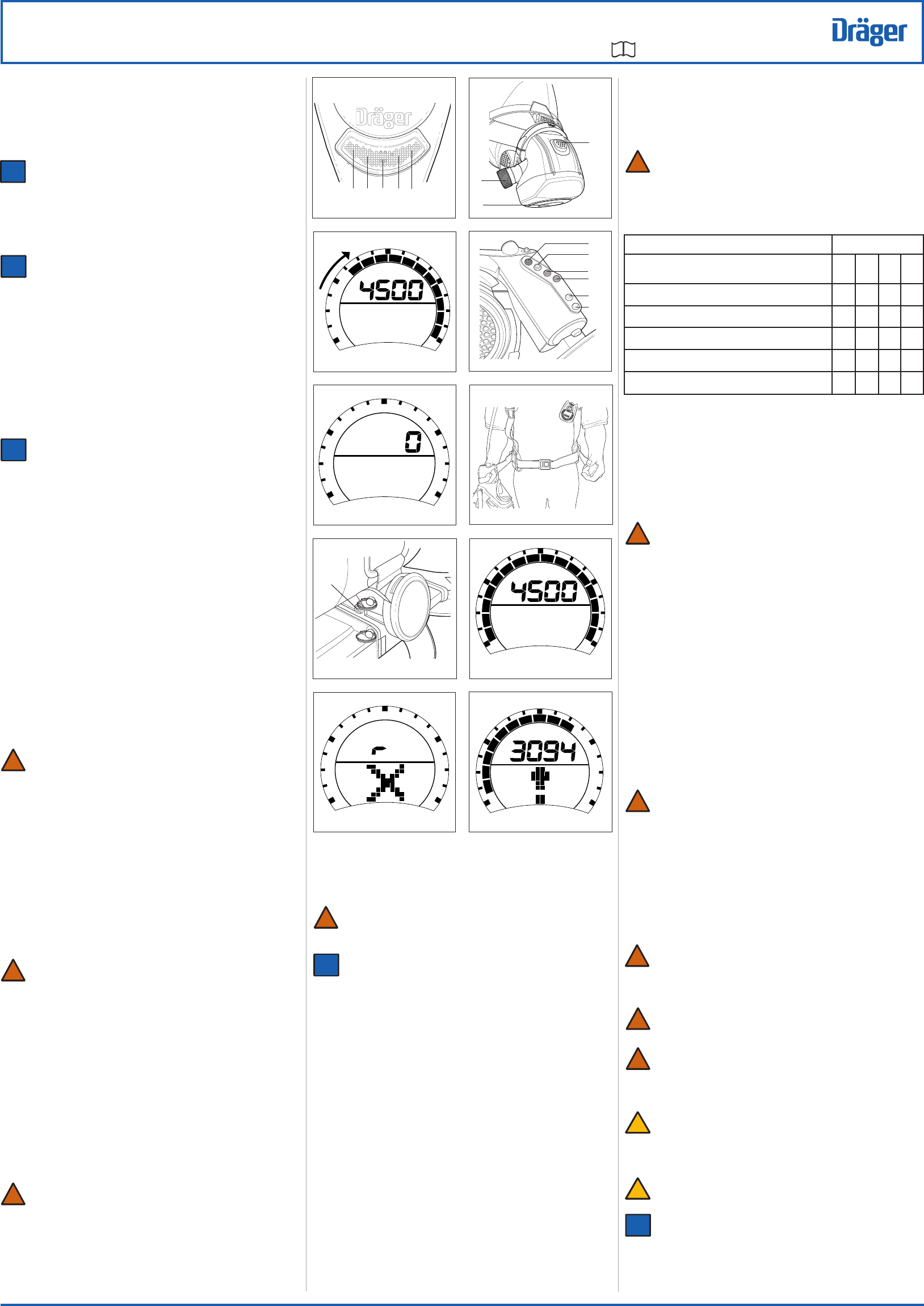
First stage – The Sentinel 7000 will emit a single tone from the user interface and
the additional alarm sounders, and the display backlight will illuminate.
Second stage – The display will show a tick symbol (Fig 7); the blue, red and green
LEDs (Fig 8) will illuminate.
Third stage – The display will show the cylinder type (Fig 9) (2216 psi or 4500
psi).
i
i
i
i
i
i
!
i
i
i
i
!
!
i
i
!
Description and Intended Use
This UI describes the Dräger PSS® 7000 Series of SCBA tted with the following:
A Dräger Sentinel 7000 electronic monitoring system, with integral personal alert
safety system (PASS).
A Dräger wireless head-up display (HUD) unit.
The Dräger PSS® 7000 is a compact and lightweight apparatus that provides the wearer
with respiratory protection when working in contaminated or oxygen-decient conditions.
The system can be used as a self-contained system or with an independent air supply
to increase eective operation time. The system is fully compatible with a wide range of
compressed-air cylinders, face masks and lung demand regulators (LDRs).
The carrying system has a height-adjustable articulating backplate (6, Fig 1) that provides
improved comfort and ease of use, resulting in increased manoeuvrability and reduced
fatigue. The carbon-composite backplate incorporates a sliding height-adjustable yoke
that has three preset positions. A exible pivot joint located at the base of the backplate
(in line with the hip of the wearer) moves in response to the twisting and bending of the
wearer, improving the weight distribution and freedom of movement. The system includes
adjustable shoulder straps (2) and waist belt (11).
The Sentinel 7000 electronic monitoring system is a multi-function system that provides
continuous monitoring of the SCBA status including remaining cylinder pressure,
movement of the wearer, main battery condition, end-of-service time (EOST) and
PASS. It provides visual indications of system status and audible and visual alarms
in warning conditions. User control and monitoring of the system is through a user
interface (1) that incorporates switches, LEDs, a liquid crystal display (LCD) display
screen and an alarm sounder. A backlight illuminates the user interface display screen
when required. Additional alarm sounders (5), with warning LEDs top and bottom, are
mounted on the backplate and operate only during PASS alarms. The operating settings
are preset and non-adjustable by the user.
The PASS function of Sentinel 7000 electronic monitoring system is an alarm system
that can be activated manually or automatically. The automatic alarm uses a motion
sensor to detect movement and activate a pre-alarm and main alarm at timed intervals
when no movement is sensed. The manual alarm is activated by a press button on the
user interface. A limitation of the PASS is that it detects movement or vibration to which
the wearer is subjected.
Power supplies include a main battery located in the backplate, a back-up battery
located the pressure module and a HUD battery located in the HUD. The system is
switched on by a press button on the user interface or by cylinder pressure felt at a
pressure module, with cylinder pressure transmitted to the pressure module through
a high-pressure hose (7). At switch on, a self test is performed and then the system
adopts the active mode where the PASS function is operational.
All variants utilise the same high-performance, rst-stage, regulator (9) tted with an
EOST mechanical whistle (10). The pressure regulator supplies medium-pressure
breathing air to a quick-release coupling (4) via a medium-pressure hose (3). Incorporated
in the rst-stage regulator is a rapid intervention crew universal air connection (RIC UAC)
(8). The RIC UAC is a male coupling that allows emergency replenishment of breathing
air to the air cylinder while wearer is breathing from apparatus.
A wireless HUD unit (refer to instruction no. 3356234) locates in the face mask and
provides visual indications to the wearer of a number of system conditions. Signals from
the Sentinel 7000 to the HUD are from a pressure transducer/transmitter incorporated
in the pressure module.
!
!
1
2394
1
2
3
5
6
7
8
9
10
4
11
i
i
1
5
3
!
User Instruction
PSS® 7000 SerieS
SeLF-CONTAiNeD BreATHiNG APPArATUS wiTH SeNTiNeL 7000
3356233 : 05 Edition : October 2008 : Subject to Modication (A3-D-P) Page of 4
i
Additional air ow required – Press and rotate the bypass button to deliver a sustained
air supply (80 to 130 litres/minute) into the face mask
Excessive or loss of air ow – Close the cylinder valve then immediately begin to
slowly reopen the valve. Use the cylinder valve as a regulating valve to set the air
ow to meet the user requirement. This procedure can also be used with ratchet-type
cylinder valves.
The air ow procedures above are emergency measures that may greatly
reduce the operating duration of the air supply. When activated the
user must immediately evacuate to a safe area. The reason for using
the procedure must be investigated and repaired before reusing the
apparatus.
Table 1 Head-up display LEDs
Key: l On
¬ Flashing
R Red
A Amber
G Green
After Use
Do not remove the SCBA until in a safe area. Do not drop or throw down
the SCBA as damage could occur.
Release and loosen all of the face mask straps.
Lift and remove the face mask.
Fully extend all of the straps of the head harness.
Close the cylinder valve.
Release the waist belt buckle, lift shoulder strap buckles to loosen and remove the
apparatus.
Press the front button (2, Fig 13) of the LDR to vent system.
Press the reset button (1) to switch o the positive pressure.
If the LDR has been set to bypass, press and rotate the bypass button (3) to switch
o the bypass.
Press and hold the RH and LH buttons of the user interface until the display clears,
then immediately release the buttons. After approximately 180 seconds, all six HUD
LEDs will ash twice to indicate that the unit has logged o.
Carry out a visual inspection of the complete SCBA including any ancillary equipment
used during the operation.
If required, lightly lubricate the LDR O-ring (recommended lubricant is Molykote 111).
Pass the SCBA to the service department, with details of any faults/damage that
occurred during use.
Removing the Cylinder
Do not attempt to remove the cylinder with the system pressurised.
Close the cylinder valve and fully vent the system.
Lift the free end of the cylinder strap from the Velcro fastening and lift the strap
against the cam-lock mechanism to release the strap tension. Loosen the strap.
Unscrew the handwheel of the rst-stage regulator from cylinder valve.
Lift and carefully slide the cylinder away from rst-stage regulator towards the top of
the backplate.
Remove the cylinder from the apparatus.
Inspect and recharge the cylinder (refer to Charging the Cylinder).
Charging the Cylinder
Air quality for compressed air cylinders must conform to the minimum
grade requirements for Type 1 gaseous air as dened in the CGA
Commodity Specication for Air, G-7.1 (Grade D or higher quality) and
where appropriate be in accordance with: NFPA 1989 Standard on
Breathing Air Quality for Emergency Services Respiratory Protection.
Recharge cylinders to the indicated working pressure marked on the
cylinder.
If the moisture content exceeds the recommended levels, ice particles
can form, reducing or blocking the airow.
Cleaning the SCBA
Use only recommended cleaning agents. Do Not use organic solvents,
such as acetone, alcohol, white spirit, trichloroethylene or similar. Do not
use any form of mechanical, electrical or ultrasonic agitation in cleaning
baths. Refer to manufacturers’ instructions when using cleaning and
disinfecting agents. Particular attention should be paid to concentration
and reaction times.
Do not exceed 86 °F for washing and rinsing solutions. Do not exceed
140 °F for drying. Do not immerse the LDR.
Recommended cleaning and disinfecting agent is liquid AirKem A-33.
Full details of cleaning and disinfecting agents are available from Dräger
on request.
Carefully clean SCBA components (use suitable cleaning baths, and immerse and
manually agitate components in solution as necessary).
Thoroughly remove any cleaning solutions by rinsing in clean water.
Dry all components, including internal parts.
When the system is empty, inhale and hold breath for approximately 8 seconds. Readjust
and retest until the face mask contracts and holds on to the face with no air leaks.
Open the cylinder valve slowly, but fully, to pressurise system.
During Use
Do not commence any operation (including supplied-air respirator (SAR)
operations) using a cylinder that is less than 80% full. The eective working
duration of the apparatus is dependent on the capacity of the air cylinder
and the breathing rate of the wearer.
On activation if the unit fails to operate, or a low battery alarm activates,
then the relevant batteries should be renewed.
Regularly observe warning and display signals, and note the following:
For emergency help or assistance, press the yellow button in the centre of the user
interface to activate the PASS alarm (see below).
To illuminate the display backlight, press and release the LH or RH button of the
user interface.
Remaining cylinder pressure is indicated on the user interface and the HUD LEDs.
The user interface shows the cylinder pressure digitally (numeric) and as an analogue
segment display (Fig 16). The HUD shows the cylinder pressure with LEDs (refer
to the Table 1). The user interface digital display is the most accurate indicator.
Remaining time to EOST alarms is indicated on the user interface as a digital (numeric)
display.
React to the following alarm and warning signals as necessary:
EOST – The user interface will emit an audible alarm tone, and red and blue LEDs
will ash; the red LED on the HUD will ash; the mechanical whistle on the rst-
stage regulator will sound.
PASS pre-alarm – A repeating audible alarm tone
will be emitted from the
user
interface
sounder and the
additional alarm sounders. Move the user interface to
cancel the alarm (do not attempt to use the buttons to switch o the pre-alarm.
PASS alarm – A
high-level sweeping alarm will be emitted from the
user interface
sounder and the
additional alarm sounders
; red and blue LEDs on the user interface
(Fig 8)
and top and bottom
of the
additional alarm sounders
(Fig 11) will ash
intermittently; the user interface will show the alarm icon (Fig 17).
Simultaneously
press and hold the RH and LH buttons of the user interface to cancel the alarm.
Low main battery – A low battery icon (Fig 4) will be displayed on the user interface
or the G/Y battery LED (Fig 14) will ash yellow.
Low HUD battery – The G/Y battery LED will ash green.
Loss of HUD communication – The HUD blue LED ash
Additional air ow can be delivered into the face mask as follows:
Press and release the bypass button (3, Fig 13) to deliver a single jet of air into the
face mask.
Fourth stage – The display will show the normal operating screen (Fig 10); the blue,
red and green LEDs (Fig 8) will illuminate; the blue and red LEDs (1, Fig 11) will
illuminate.
End of sequence – Two ‘trill’ alarms will sound; the display will show the normal
operating screen (Fig 10); the green LED (Fig 8) will ash at approximately one
second intervals to conrm that the Sentinel 7000 has passed the self check and is
in the active mode.
If a cross icon (Fig 12) with a fault code is displayed, the Sentinel 7000
has failed the self check. Contact Dräger for repair.
Press and hold the RH and LH buttons of the user interface until the display clears,
then immediately release the buttons.
High-Pressure Leak and EOST Warning Test
The following is not intended as a test of HUD functionality. If the HUD fails
to operate as described, refer to the HUD UI (instruction no. 3356234).
Place the face mask next to the SCBA (within three feet of the pressure module).
Press the reset button (1, Fig 13) of the LDR to switch o the positive pressure.
Open the cylinder valve slowly, but fully, to pressurise system. The Sentinel 7000
and HUD systems will activate as follows:
The Sentinel 7000 will emit a single tone and will commence a self-check sequence
(refer to Sentinel 7000 Self Check).
Up to approximately 45 seconds after the start of the self check, all six HUD LEDs
(Fig 14) will ash twice to indicate that the Sentinel 7000 is communicating with
the HUD.
Depending on cylinder pressure, some of the line of four HUD LEDs (red/amber/
green/green) will ash (on for 15 seconds/o for 45 seconds).
Close the cylinder valve and observe the user interface display. The pressure reading
shall not decrease more than 200 psi in 1 minute.
If the SCBA fails this test, or an immediate leak is evident, do not continue
with the check. Vent the pressure, switch o the system and contact
Dräger for repair.
Cover the outlet of the LDR with the ball of the hand and press the front button (2,
Fig 13).
Carefully lift the ball of the hand to slowly vent the system – observe the pressure
displayed on the user interface.
Note the pressures for the electronic EOST activation (indicated by an audible alarm
tone; ashing red and blue LEDs on the user interface; ashing red LED on the
HUD) and the mechanical whistle operation. Electronic and Mechanical activation
does not need to be simultaneous but both must be within the acceptable range (refer
to Technical Data – EOST Alarms). Refer to the Service Manual if the pressures are
outside the acceptable range.
Allow the system to vent to zero pressure. The display will show zero pressure and all
of the user interface LEDs (Fig 8) will ash at approximately one second intervals.
The green LED indicates that the system is still in active mode.
Press and hold the RH and LH buttons of the user interface until the display clears,
then immediately release the buttons.
The HUD red LED (Fig 14) will ash intermittently.
After approximately 180 seconds all six HUD LEDs will ash twice to indicate that the
unit has logged o from the Sentinel 7000.
Press the reset button of the LDR to switch o the positive pressure.
Check that the face mask port and the connector O-ring of the LDR are clean and
undamaged.
Align and push the LDR into face mask port until it latches in position.
Check the attachment by attempting to pull the LDR away from the face mask.
Normal Operation
All safety information, including the preliminary safety details, must be read
and understood before commencing any user task. The procedures detailed
in this UI may only be carried out by trained and competent SCBA users.
Before use checks
Carry out a visual inspection of the complete SCBA including any ancillary equipment
that will be used during the operation. The tasks detailed in the preparation for use
and the pre-operational checks sections must also be completed satisfactorily before
release of the SCBA for operational use. Components that are worn or damaged must
be repaired or replaced before proceeding. Do not use the equipment if any of the
following is found:
The SCBA fails to meet any of the test specications.
Any casing is cracked or broken.
The LCD display of the user interface cannot be read, or one or more of the display
segments is inoperative.
Audible and/or visual alarms are not functioning.
Any fault icon shown.
Putting on the Apparatus
This apparatus may only be worn by trained and competent personnel.
The user must ensure that any accessories, ancillary equipment, turnout
gear and other clothing items do not interfere with the SCBA and do not
create a safety hazard.
If necessary, adjust the backplate height (refer to Adjust the Backplate Height).
Loosen the shoulder straps and waist belt and put on the SCBA.
Check that the shoulder pads are not twisted and take the weight of the system on the
shoulders by pulling the shoulder straps. Do not fully tighten at this stage.
Close the waist belt buckle and pull the ends of the waist belt forward until the strap
padding ts securely and comfortably over the hips (Fig 15). Tuck the belt ends
behind the hip pads.
Pull the shoulder straps until the SCBA rests securely and comfortably on the hips.
Do not overtighten. Tuck the strap ends behind the waist belt.
Fully loosen the head straps of the face mask and place the neck strap over the back
of the neck.
Press the reset button (1, Fig 13) of the LDR to switch o the positive pressure.
Open the cylinder valve slowly, but fully, to pressurise system. The Sentinel 7000 and
HUD systems will activate.
Putting on the Face Mask
Use only the mask sizes that have been conrmed by a quantitative t
test (QNFT).
Select the correct size of mask and inner mask.
Put on the face mask (for non-CBRN use, refer to instruction no. 9021649; for
CBRN use, refer to instruction no. 3356259).
Press the front button (2, Fig 13) of the LDR and check that air ow is delivered into
the face mask.
Press the reset button (1) to stop the air ow.
Close the cylinder valve and breathe normally to empty the system of pressure.
LEDs
Cylinder
Contents
R A G G
Full to 3/4 l l l l
3/4 to 1/2 l l l
1/2 (for 20 secs once) l ¬
1/2 to 1/4 l l
1/4 to approx. 100 psi ¬
10
2192
psi
8
2200
BR
G
R B
2210
11
1
12
2201
psi
15
2193
17
2198
psi
16
2202
psi
13
2117
1
14
2189
R
A
G
G
B
G/Y
LED
!
!
!
!
!
!
!
!
!
!
!
!
9
2190
psi
i
i
i
i
2
3
i
i
i
i
2
i
i

User Instruction
PSS® 7000 SerieS
SeLF-CONTAiNeD BreATHiNG APPArATUS wiTH SeNTiNeL 7000
3356233 : 05 Edition : October 2008 : Subject to Modication (A3-D-P) Page of 4
i
RIC UAC Use
Use of the RIC UAC should be by trained and competent personnel only.
The RIC UAC lling hose is a required component of the NFPA 1981 certication.
Only use a lling hose which has been certied to NFPA 1981 for use in immediately
dangerous to life or health (IDLH) atmospheres.
Do not use the RIC UAC connection for second person (buddy-breather).
Do not use the RIC UAC support pack to transfer air from one compressed air
breathing apparatus to another.
Do not allow oil, grease or other contaminants to contact the RIC UAC connection.
Do not attempt to disassemble or repair the RIC UAC connection.
Caution: The secondary air supply pressure to the RIC UAC must not exceed maximum
rated working pressure of the cylinder(s) being lled.
Caution: If the pressure relief valve of the RIC UAC is activated, the SCBA must be
returned to the nearest Dräger branch or agent.
Caution: If a leak is detected while relling in a contaminated or oxygen-decient
gaseous atmosphere, stop relling and immediately leave the hazardous area.
Contact Details
Any issues with the equipment, including damage, malfunction, or failure of the
breathing apparatus that may present a hazard to the user should be reported
to:
Draeger Safety, Inc.
101 Technology Drive
Pittsburgh
PA15275
Phone: 1-800-922-5518
Fax: 1-800-922-5519
Contact with the certication organisations may be reached at:
NIOSH, NPPTL
Phone: 1-800-232-4636
SEI (NFPA)
1307 Dolley Madison Blvd
Suite 3A, McLean
VA 22101
Phone: 1-703-442-5732
Storage (Ready for Use)
Fully extend the shoulder straps, waist belt and head harness straps.
Store apparatus in a cool dry environment, free from dust and dirt (do not expose to
direct sunlight).
When the SCBA is stored with the cylinder tted, the apparatus must be supported
by the cylinder and not the backplate.
Remove the batteries if the equipment is not used for long periods (a small amount
of discharge occurs during storage).
Special instructions
Use of an Independent Air Supply (SAR Airline Connection)
Air quality must conform to the statutory requirements.
Use of an airline connection by a second person (buddy-breather) voids
NIOSH approval.
The time required for the wearer to escape to a safe area must be within the
remaining breathing time of the cylinder, taking into account the remaining
air content in the cylinder and the breathing rate of the wearer.
Independent air supplies must meet the following standards:
Type-1 gaseous air as dened in: CGA Commodity Specication for Air, G-71 (grade
D or higher)
NFPA 1989 Standard on Breathing Air Quality for Fire and Emergency Services
Respiratory Protection
Air supply pressure – 87 psi to 125 psi
Airline hose length – 5 feet to 300 feet (maximum working hose length must not
exceed 12 individual hose lengths)
Airline ow rate – 550 litres/minute
Approved for use at temperatures above minus 25 degrees Fahrenheit (minus 31.7
degrees Centigrade).
Sentinel 7000 alarms and warning signals will operate as normal.
The user interface display will show cylinder pressure when the cylinder
valve is open.
Turn on the independent air supply.
Connect the independent air supply coupling to the secondary supply hose (refer to
instruction no. 3355853) and breathe normally.
Close the cylinder valve (if the EOST warning signal activates, silence by taking several
short deep breaths or momentarily operating the LDR bypass button (3, Fig 13).
If any air supply problems are encountered, proceed as follows:
Open the cylinder valve to return to breathing from the attached cylinder.
Disconnect the independent air supply coupling.
Leave the hazardous area by the shortest and safest escape route, if necessary.
Cautions and Limitations
D – Air-line respirators can be used only when the respirators are supplied with respirable
air meeting the requirements of CGA G – 7.1, Grade D or higher quality.
E – Use only the pressure ranges and hose lengths specified in the User's
Instructions.
I – Contains electrical parts that may cause an ignition in ammable or explosive
atmospheres.
J – Failure to properly use and maintain this product could result in injury or death.
M – All approved respirators shall be selected, tted, used, and maintained in accordance
with MSHA, OSHA, and other applicable regulations.
N – Never substitute, modify, add, or omit parts. Use only exact replacement parts in
the conguration as specied by the manufacturer.
O – Refer to User's Instructions and/or maintenance manuals for information on use and
maintenance of these respirators.
S – Special or critical User's Instructions and/or specic use limitations apply. Refer to
User's Instructions before donning.
CBRN Use
The Dräger PSS® 7000 Series is certied by National Institute for Occupational Safety
and Health (NIOSH), for limited chemical, biological, radiological or nuclear (CBRN)
use and by the Safety Equipment Institute (SEI) to meet the requirements of NFPA
1981. Approvals are only valid when the apparatus is used with compressed air cylinders
approved by NIOSH. Equipment congurations for CBRN use are detailed in a CBRN
Approval Label (refer to instruction no. 3356226).
If an FPS NFPA LDR, Dräger recommend that a quantitative t test (QNFT) be performed
on the face mask before use in a CBRN environment. The t test must be conducted
strictly in accordance with the requirements outlined in the OSHA Respiratory Protection
Standard 29 CFR, Section 1910.134.
Q – Use in conjunction with personal protective ensembles that provide appropriate levels
of protection against dermal hazards.
R – Some CBRN agents may not present immediate eects from exposure, but can
result in delayed impairment, illness or death.
T – Direct contact with CBRN agents requires proper handling of the SCBA after each
use and between multiple entries during the same use. Decontamination and disposal
procedures must be followed. If contaminated with liquid chemical warfare agents,
dispose of the SCBA after decontamination.
U – The respirator should not be used beyond 6 hours after initial exposure to chemical
warfare agents to avoid possibility of agent permeation.
S – Special or Critical Users’ Instructions
Approved for use at temperatures above minus 25 degrees Fahrenheit (minus 31.7
degrees Centigrade).
When used as a combination supplied-air respirator/self-contained breathing apparatus
(SAR/SCBA), not more than 20 per cent of the air supply can be used during
entry.
During supplied air use, the cylinder valve must remain closed. If the supplied air
fails, open the cylinder valve and immediately proceed to fresh air.
Supplied air source must meet the following criteria: pressure 87 – 125 psi, air ow
rate at least 550 litres/minute.
Important Note: If it is decided to exit the working area with the airline disconnected
or, in an emergency, if the air supply fails, breathe normally and immediately
proceed as follows:
Open the cylinder valve (counterclockwise) slowly, but fully and breathe normally.
Disconnect the hose of the independent air supply from the male coupling of the
airline hose connection. Breathe normally and immediately leave the hazardous area
by the shortest and safest route.
Safety Warning: The remaining duration begins from the time of opening the
cylinder valve and disconnecting the independent air supply. The time required to
allow the wearer to escape to a safe area must be within the remaining air capacity
(volume) of the cylinder taking into account the breathing rate of the wearer.
i
i
!
3
User Instruction
PSS® 7000 SerieS
SeLF-CONTAiNeD BreATHiNG APPArATUS wiTH SeNTiNeL 7000
3356233 : 05 Edition : October 2008 : Subject to Modication (A3-D-P) Page of 4
i
Equipment Maintenance Procedures
Tasks identied in Tables 2 or 3 as maintenance tasks are to be carried out by trained and competent personnel only (authorised by
Dräger). Refer to the maintenance manual for further information.
Equipment servicing
Dräger recommend that regular inspection, testing and servicing of equipment be carried out in accordance with Table 2 below. The
table applies also to out-of-use (stored) equipment.
Records of inspections and servicing are to be maintained in line with NFPA 1852 – Standard on Selection, Care, and Maintenance
of Open-Circuit Self-Contained Breathing Apparatus.
Refer also to the maintenance information for all accessories used (face mask, LDR, HUD, etc.).
Dräger, while endeavouring to ensure correctness of statements
of fact and advice contained in this publication,gives no guarantee
or warranty in respect thereof, and accepts no liability for any
misstatement or inaccuracy in publication, or for any omission
therefrom.
Dräger Safety UK Limited
Ullswater Close
Riverside Business Park
Blyth
Northumberland NE 24 4 RG
Dräger Safety AG & Co. KGaA
Revalstraße 1
D-23560
Lübeck
Germany
Telefon: 0049451882-0
Telefax: 0049451882-2080
Internet http://www.draeger.com
Tel: +44 1670 352891
Fax: +44 1670 356266
Draeger Canada Ltd.
Mississauga, Ontario,
Canada
(905) 821-8988
Draeger Safety, Inc.
101 Technology Drive
Pittsburgh
PA 15275
Phone: 800-922-5518
Fax: 800-922-5519
http://www.draeger.com
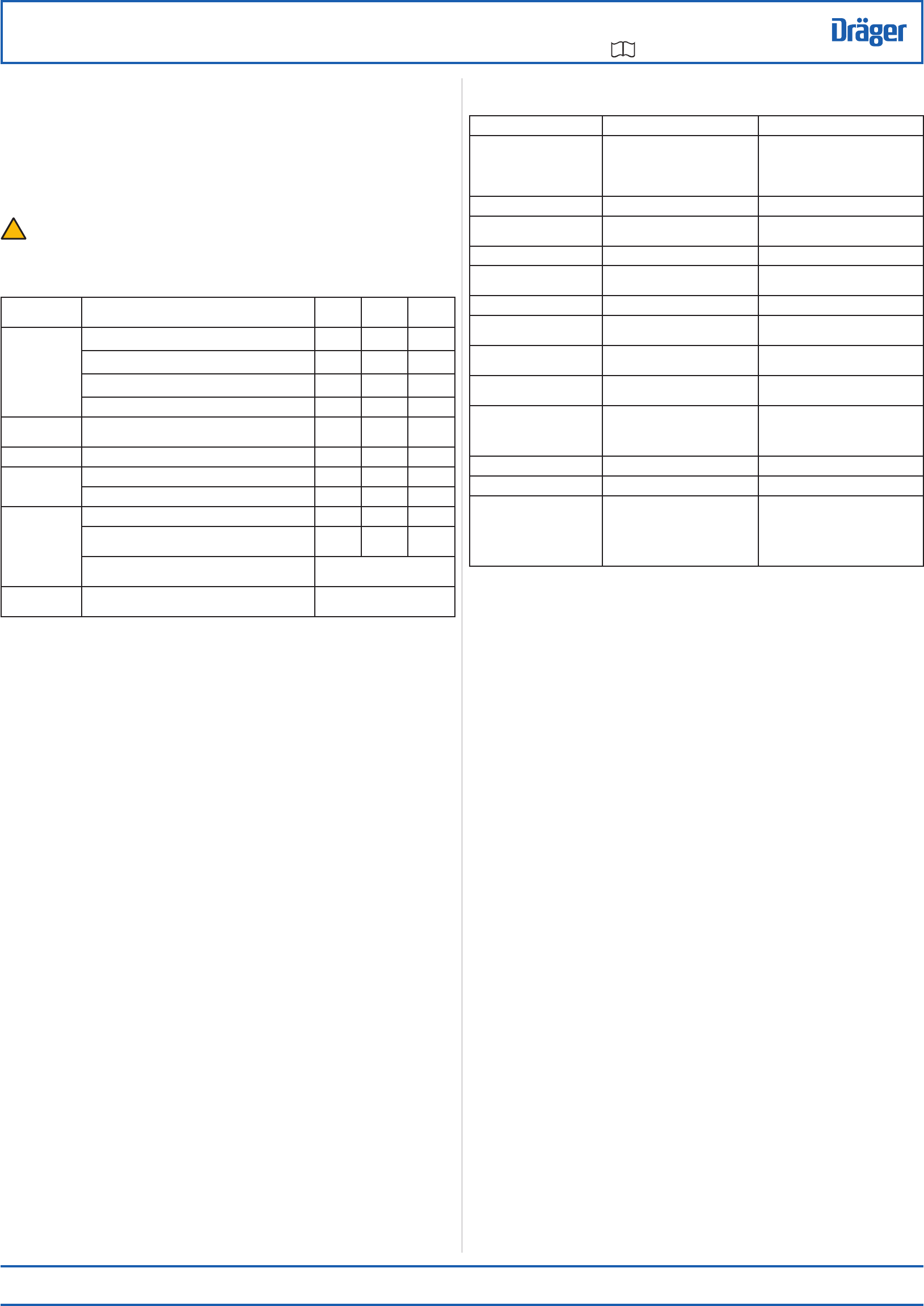
Table 2
Equipment servicing
Description After Use Every
Month
Every
Year
Complete
Equipment
Visual inspection m
Clean m
Pre-operational checks m
Flow and static tests (maintenance task) m
LDR
connector O-ring
Check and lubricate if necessary
(recommended lubricant is Molykote 111)
m
Back-up battery Renew m
First stage regulator Medium-pressure check (maintenance task) m
Renew HP connector O-ring (maintenance task) m
Cylinder Charge to correct pressure m
Checkthe initial test date stamped on the cylinder
(composite cylinders over 15 years old must be retired)
m
Cylinder pressure test Carry out in line with national
regulations
Cylinder valve Basic overhaul During cylinder pressure test or on
condition
Symptom Fault Remedy
Face mask air leak O-ring at LDR to facepiece connection
Headstraps not tight
Exhalation valve leaking
Speech diaphragm defective
Renew or lubricate O-ring
Tighten
Maintenance task
Maintenance task
Unsatisfactory communication Speech diaphragm defective Maintenance task
High-pressure air leak Loose connections
Faulty or missing hose seals
Maintenance task
Maintenance task
Safety relief valve venting First-stage regulator defective Maintenance task
LDR allowing constant air ow into
the fask mask
Bypass button engaged
Internal fault
Turn o the bypass button (3, Fig 13)
Maintenance task
Whistle not sounding correctly Whistle dirty or faulty Maintenance task
Whistle sounding continuously Damaged sealing on HP capillary
Defective activation mechanism
Maintenance task
Maintenance task
Low battery indication on the user
interface (Fig 4)
Low main battery Renew the main battery
Fault code indication on the user
interface (Fig 12)
Sentinel 7000 failure Maintenance task
Sentinel 7000 will not switch on Low main battery
Low cylinder pressure (below 145psi)
Unknown
Renew the main battery
Recharge cylinder to maximum working
pressure
Maintenance task
HUD battery LED ashing green Low battery - HUD Renew the HUD battery
HUD battery LED ashing yellow Low main battery Renew the main battery
HUD will not log on to the
Sentinel 7000
HUD not close enough
Low HUD battery
Low cylinder pressure (below 100 psi)
Unknown
Move the HUD to within three feet of the
pressure module
Renew the HUD battery
Recharge cylinder to maximum working
pressure
Maintenance task
4
!
Table 3
Troubleshooting