DragonWave DWR24-000002 24GHz AirPair Point-Point Radio Unit User Manual 1
DragonWave Inc. 24GHz AirPair Point-Point Radio Unit 1
UserManual.wiki
>
DragonWave
>
DWR24 000002 User Manual
AirPair Product Manual
Navigation menu
Upload a User Manual
Namespaces
Wiki Guide
HTML
PDF
Info
Views
User Manual
Discussion / Help
Navigation


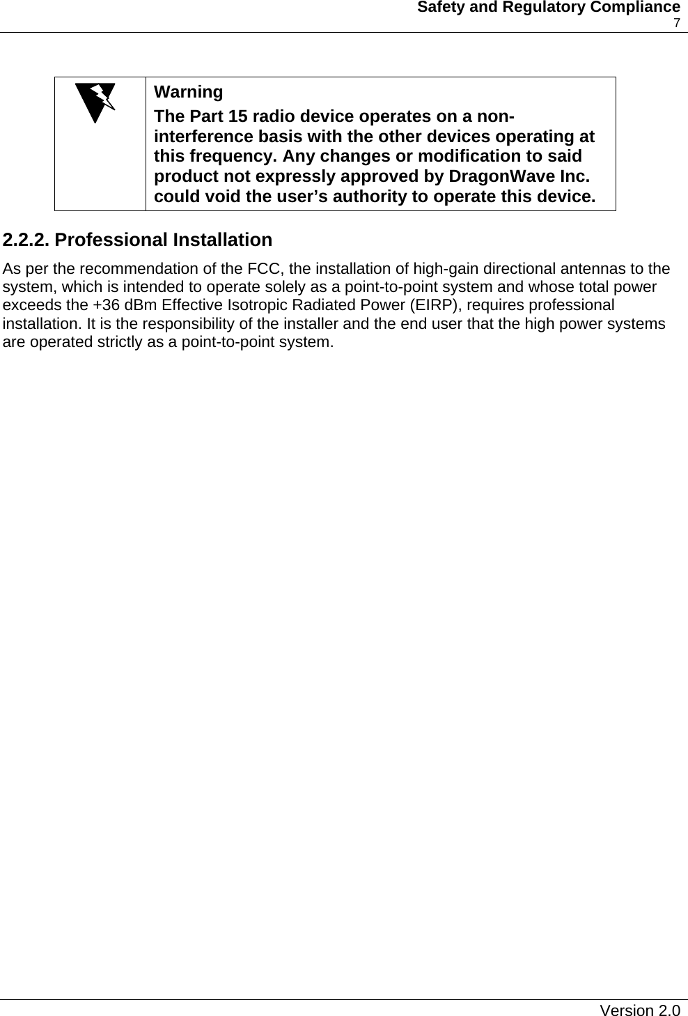

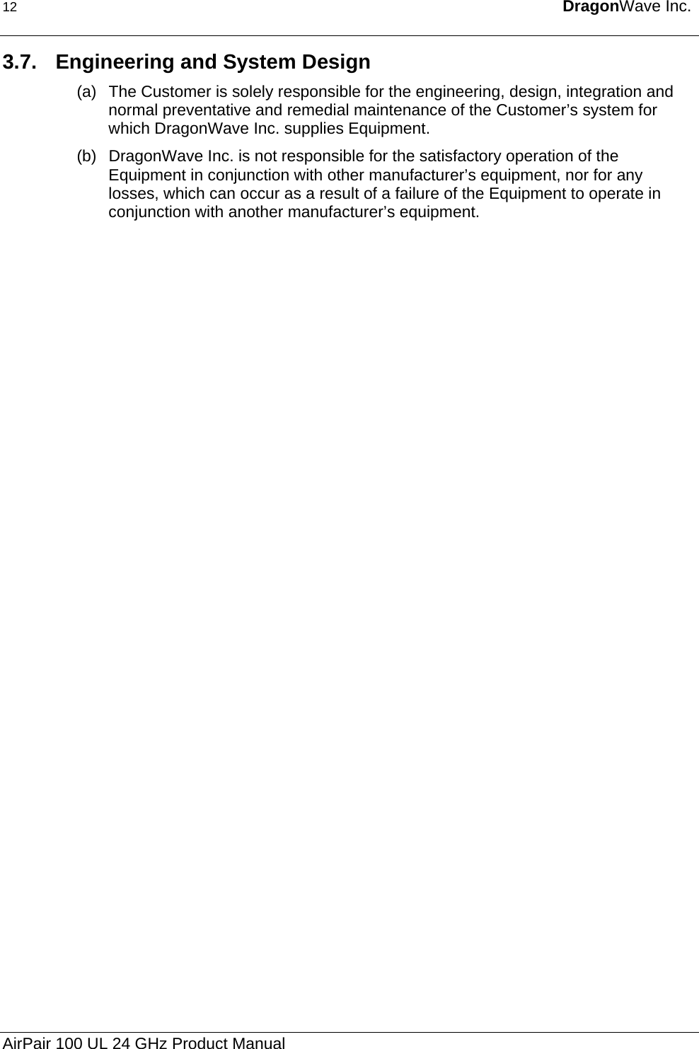
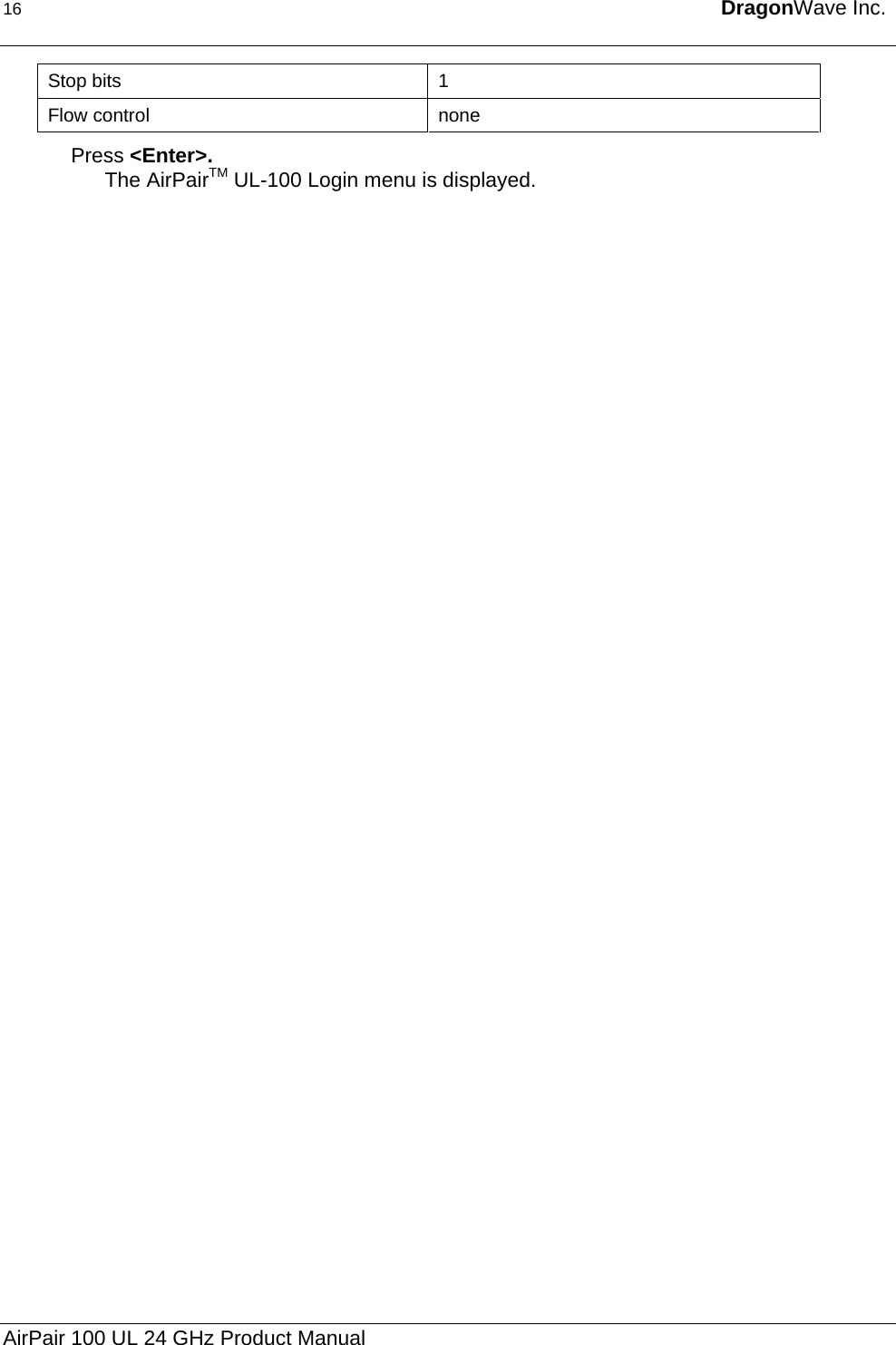
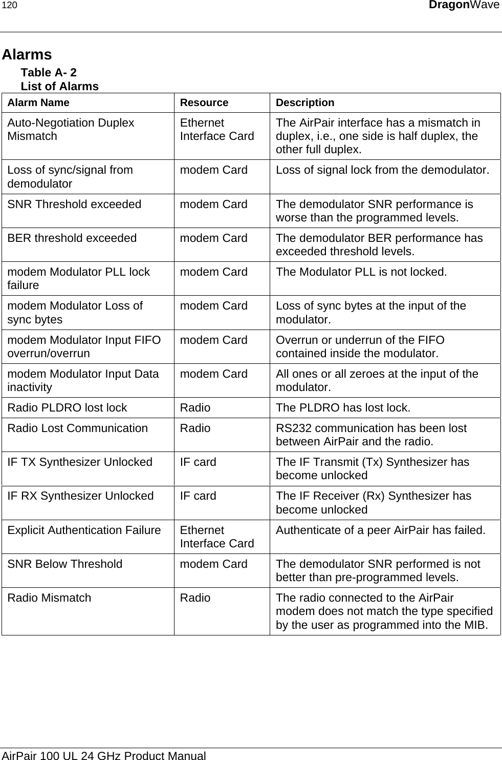
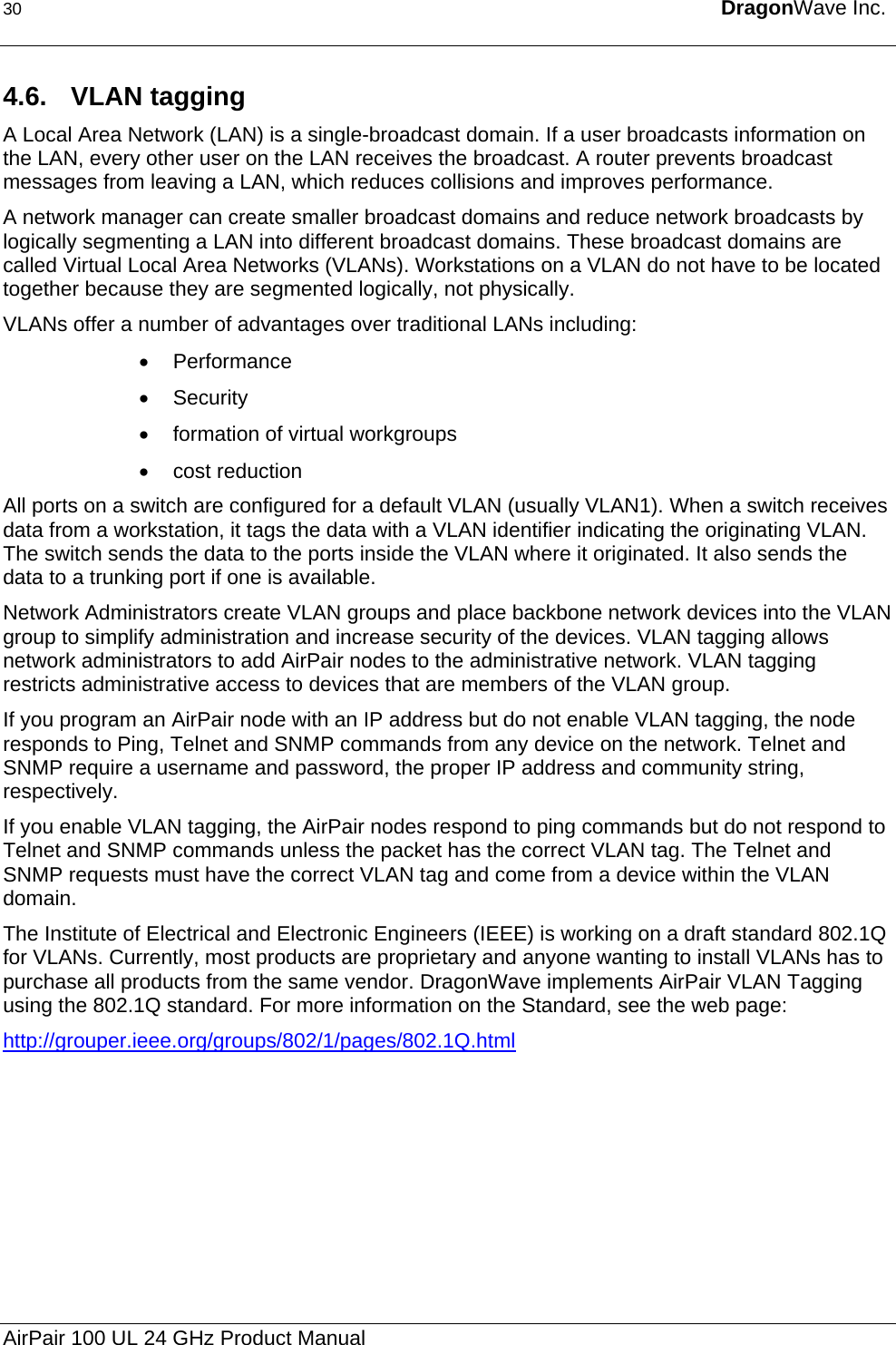
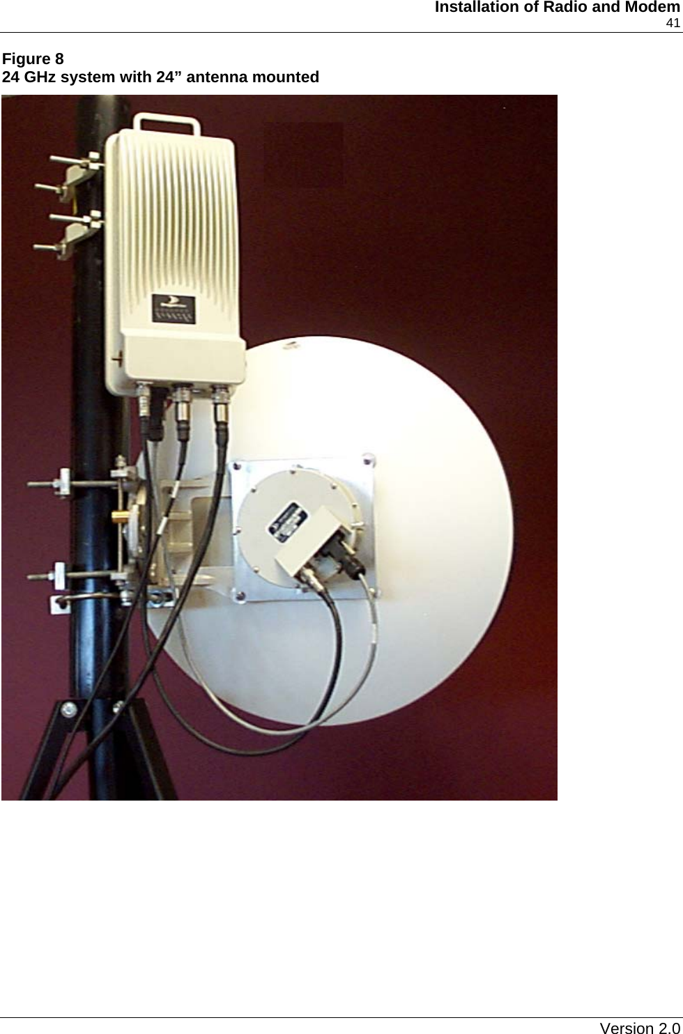
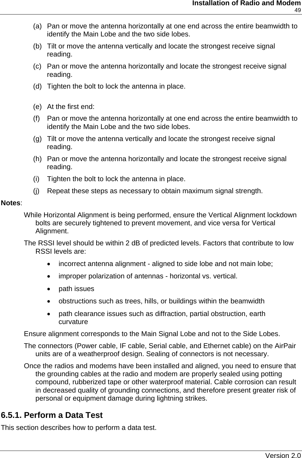
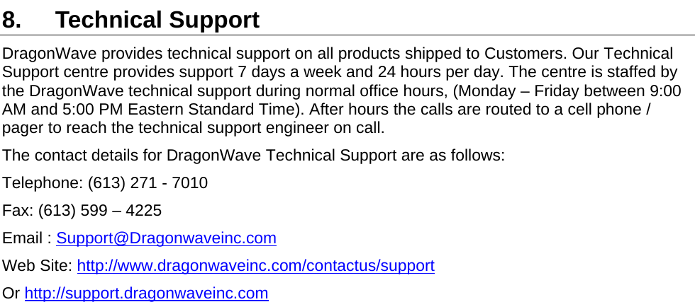
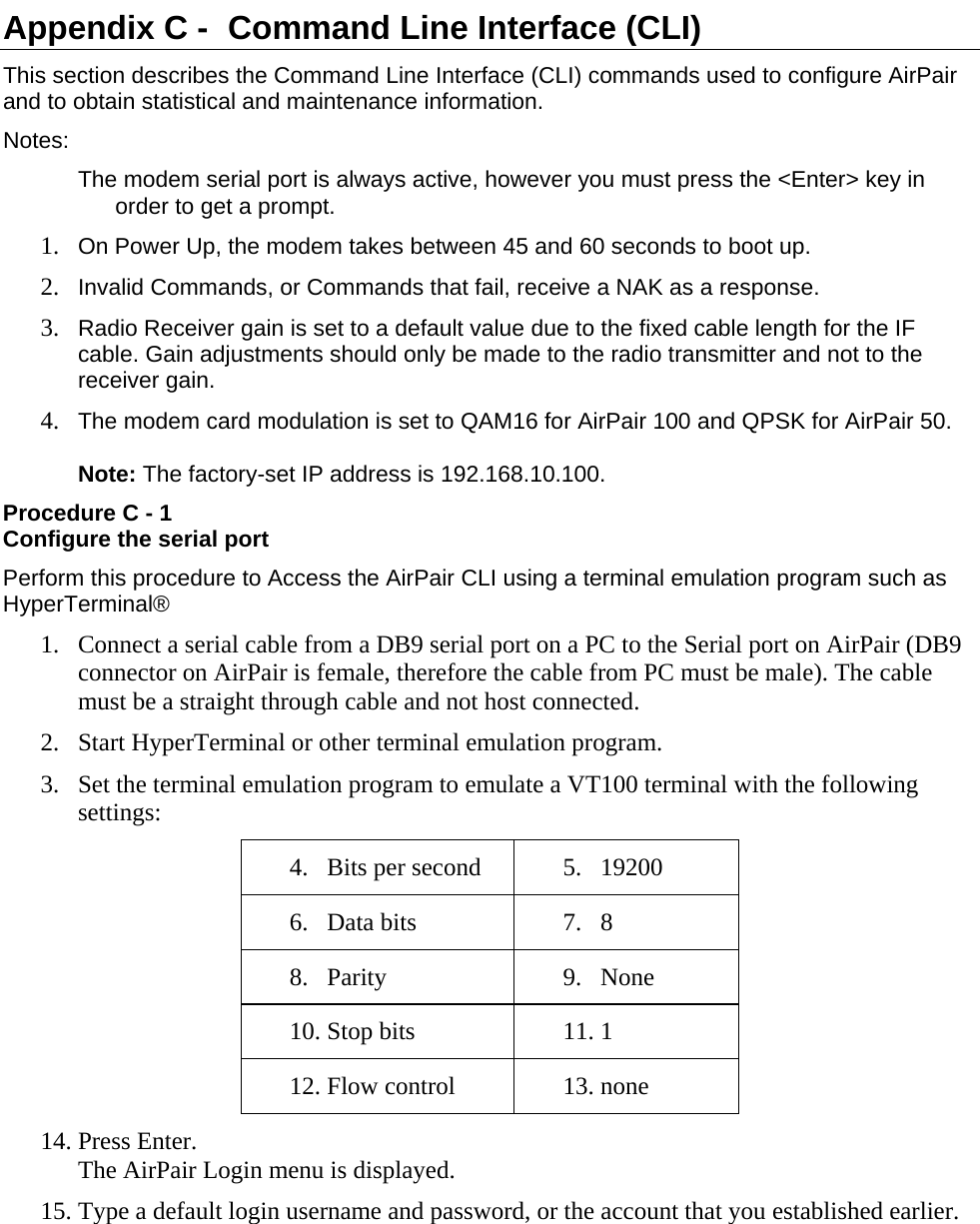
![Description 21 Required Action Steps get radio band Displays the type (band) of radio that the user expects to connect to the modem. Sequence: get radio band press Enter The system responds: Currently selected Radio Band :[none/fcc18a/fcc18b/fcc18c/ ic18a/ic18b/ic18c/fcc23a/fcc23b/fcc23c/fcc23d/ic23a/ic23b/ fcc28a/fcc28b/china23/un24/etsi23a_28/etsi23a_56/ etsi26b_28/etsi26b_56] Radio Bands Available in the system : none fcc18a fcc18b fcc18c ic18a ic18b ic18c fcc23a fcc23b fcc23c fcc23d ic23a ic23b fcc28a fcc28b china23 un24 etsi23a_28 etsi23a_56 etsi26b_28 etsi26b_56 FCC = United States Federal Communications Commission IC = Industry Canada China = China ETSI = European Telecommunications Standards Institute UN = Unlicensed set radio band [none / un24] Sets the band of radio to which the user expects to connect the modem. Sequence: set radio band [band] press Enter where band is none / un24 The system responds: Radio band Selected [none/un24]. Version 2.0](https://usermanual.wiki/DragonWave/DWR24-000002/User-Guide-399418-Page-29.png)
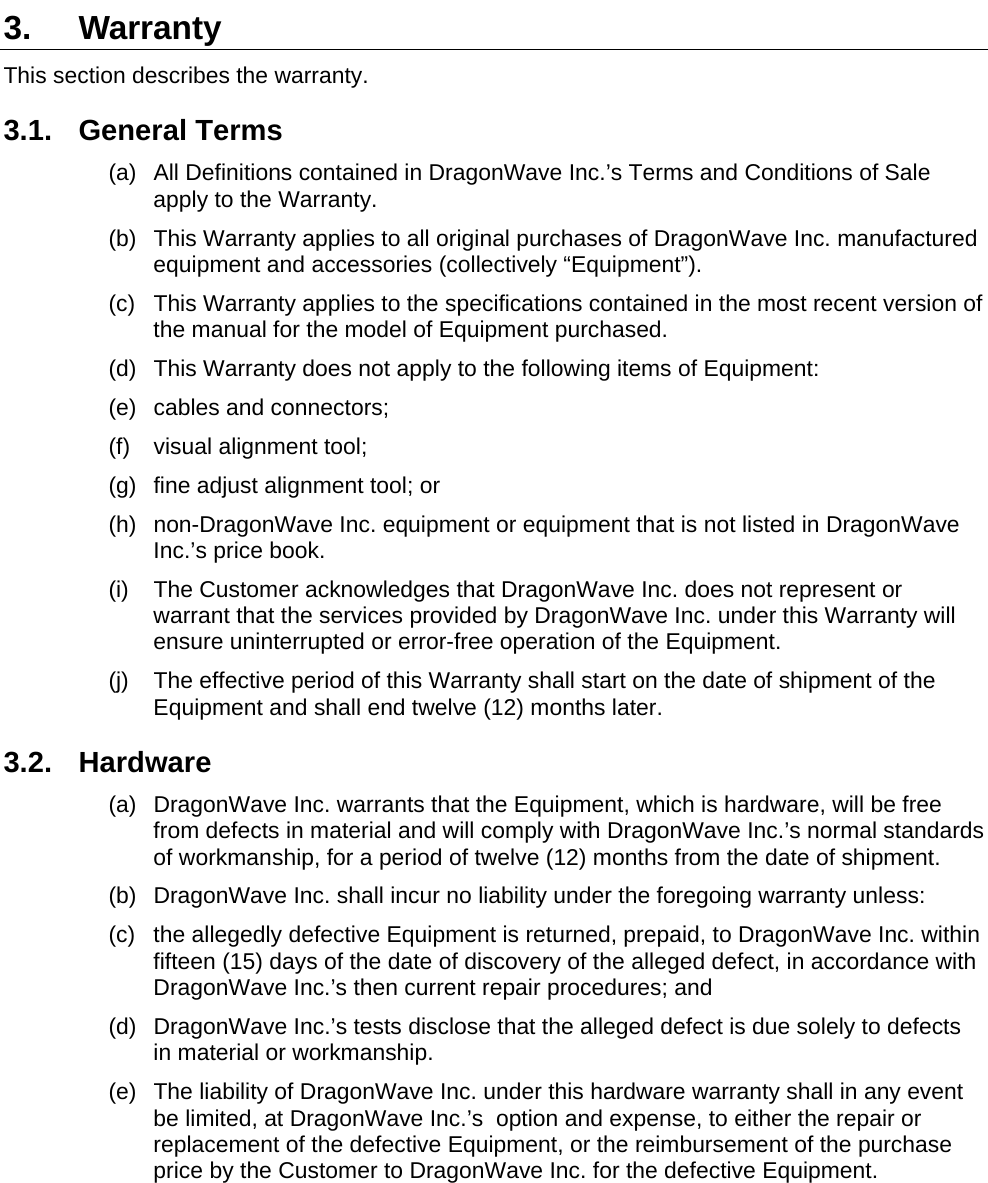
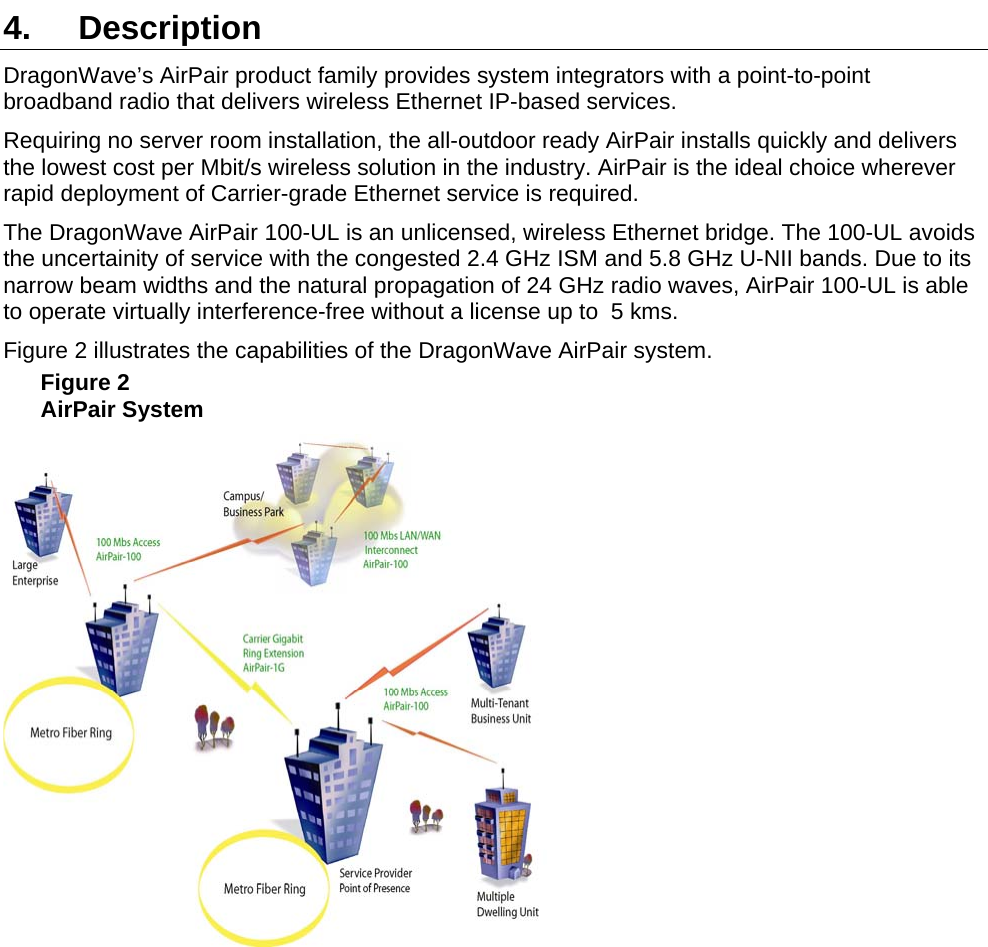
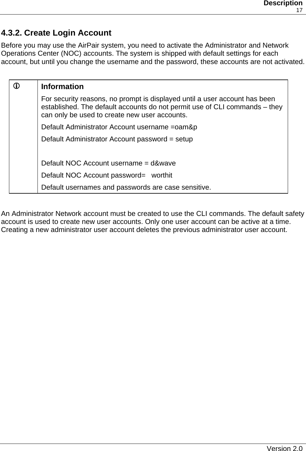
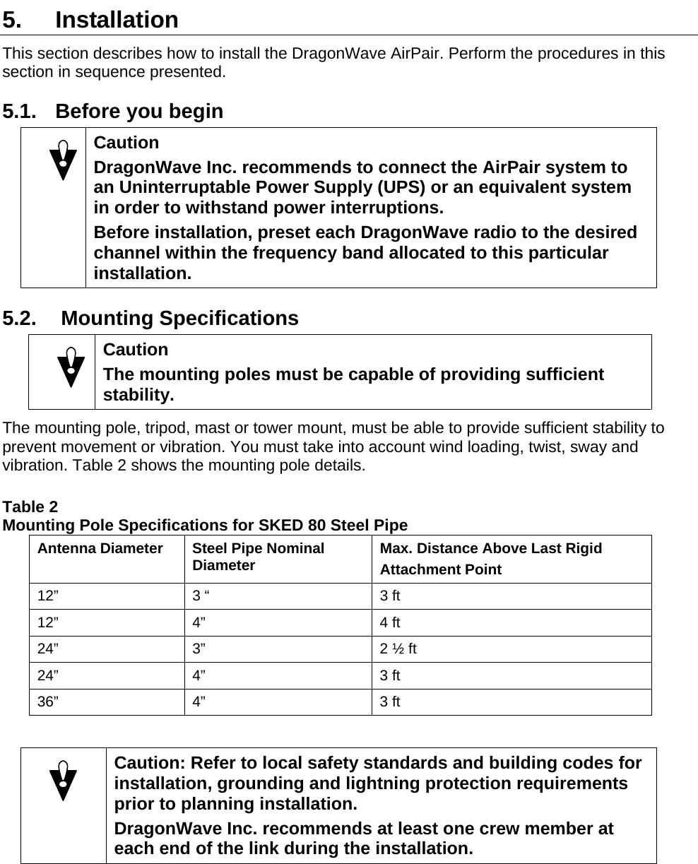
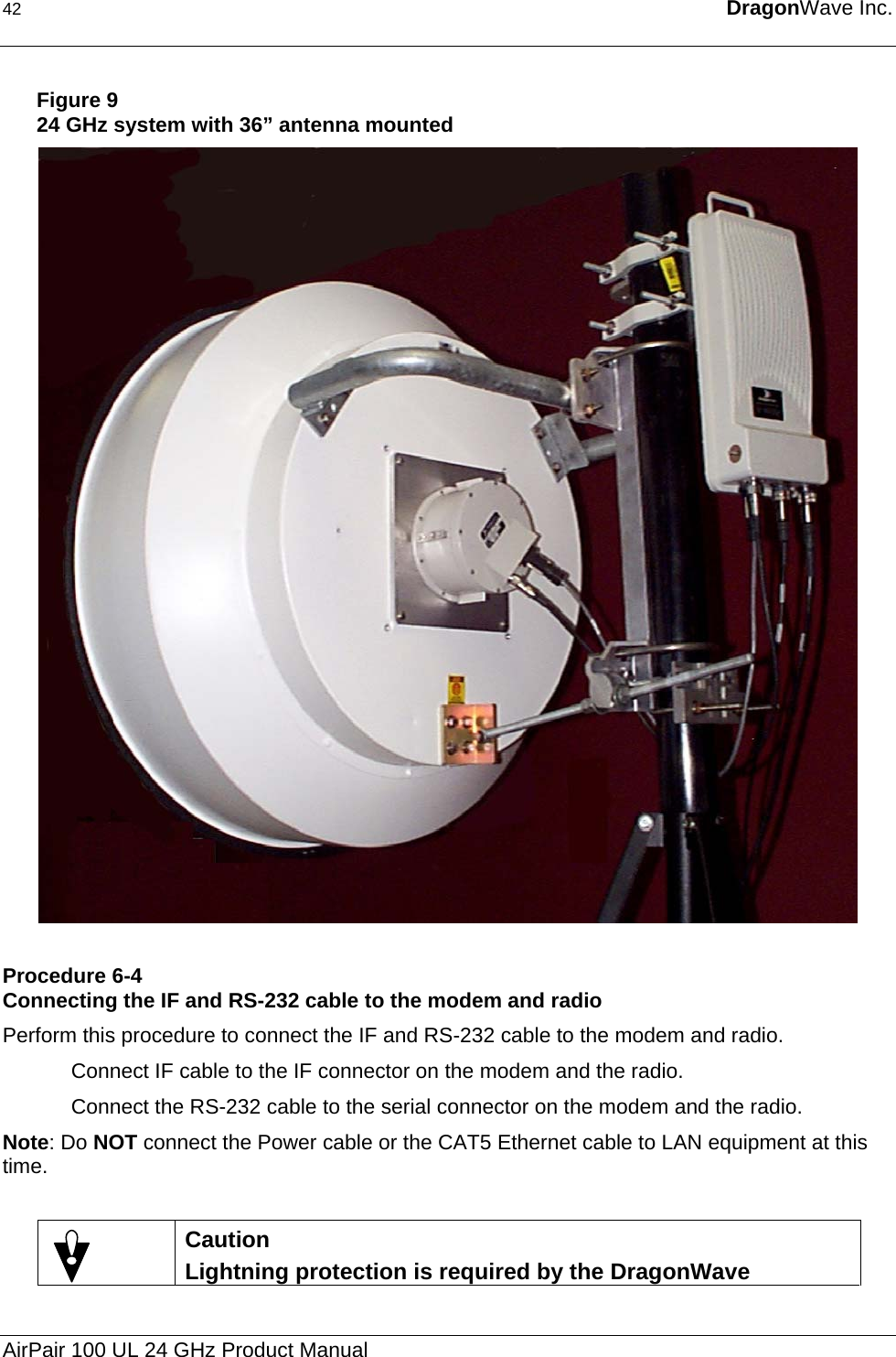
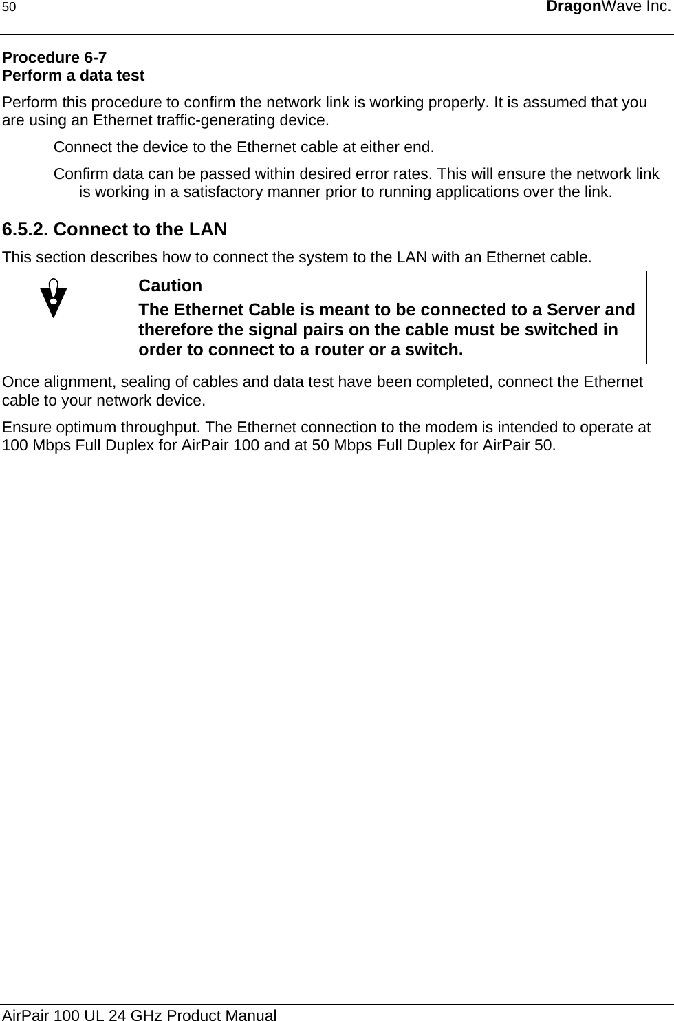
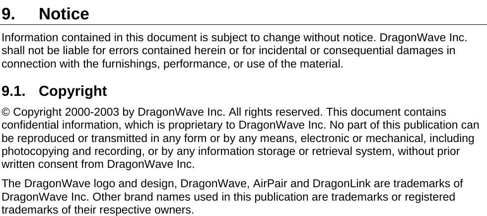
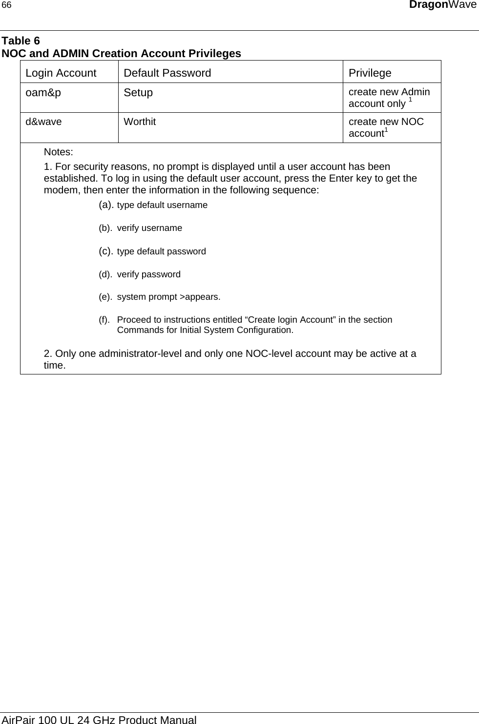
![22 DragonWave Inc. Required Action Steps get frequency bank Displays the frequency bank. Sequence: get frequency bank press Enter The system responds: un24 go FREQUENCIES(Selected) Index TX IF RX IF TX RF RX RF UNL1 670 2000 24080 24150 UNL2 660 1990 24090 24160 UNL3 650 1980 24100 24170 UNL4 640 1970 24110 24180 UNL5 630 1960 24120 24190 UNL6 620 1950 24130 24200 UNL7 610 1940 24140 24210 UNL8 600 1930 24150 24220 return FREQUENCIES Index TX IF RX IF TX RF RX RF UNL'1 600 2070 24150 24080 UNL'2 590 1990 24160 24090 UNL'3 580 2050 24170 24100 UNL'4 570 2040 24180 24110 UNL'5 560 2030 24190 24120 UNL'6 550 2020 24200 24130 UNL'7 540 2010 24210 24140 UNL'8 530 2000 24220 24150 Note: All Frequencies in MHz. set frequency bank Sets the frequency bank. Sequence: set frequency bank [go/return] press Enter The system responds: Frequency Bank selected: [go/return] AirPair 100 UL 24 GHz Product Manual](https://usermanual.wiki/DragonWave/DWR24-000002/User-Guide-399418-Page-30.png)
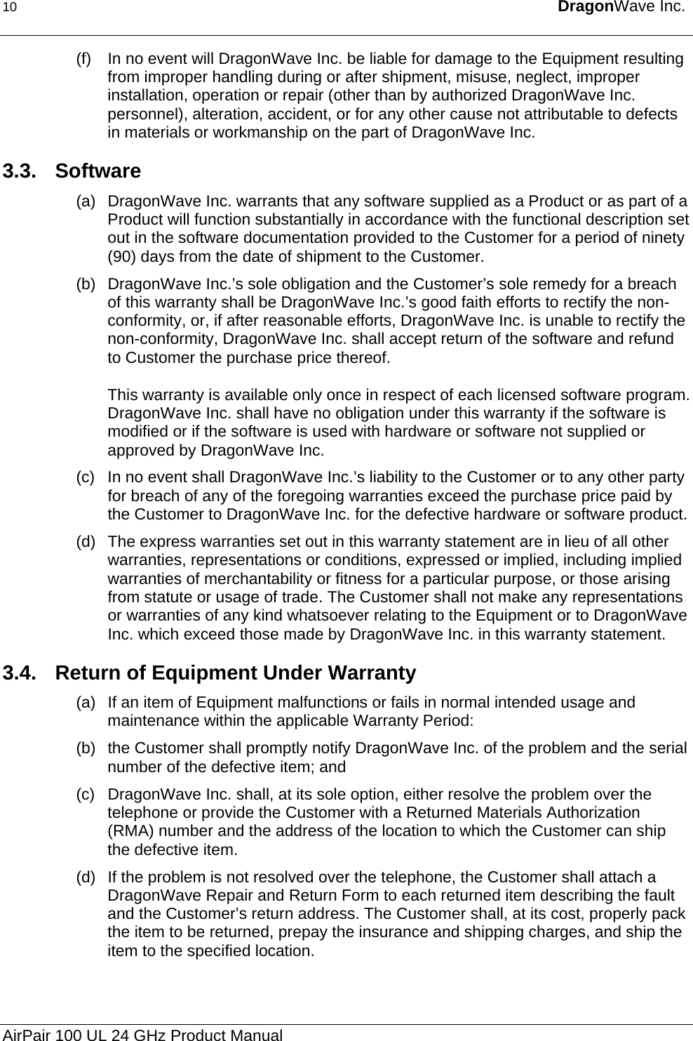
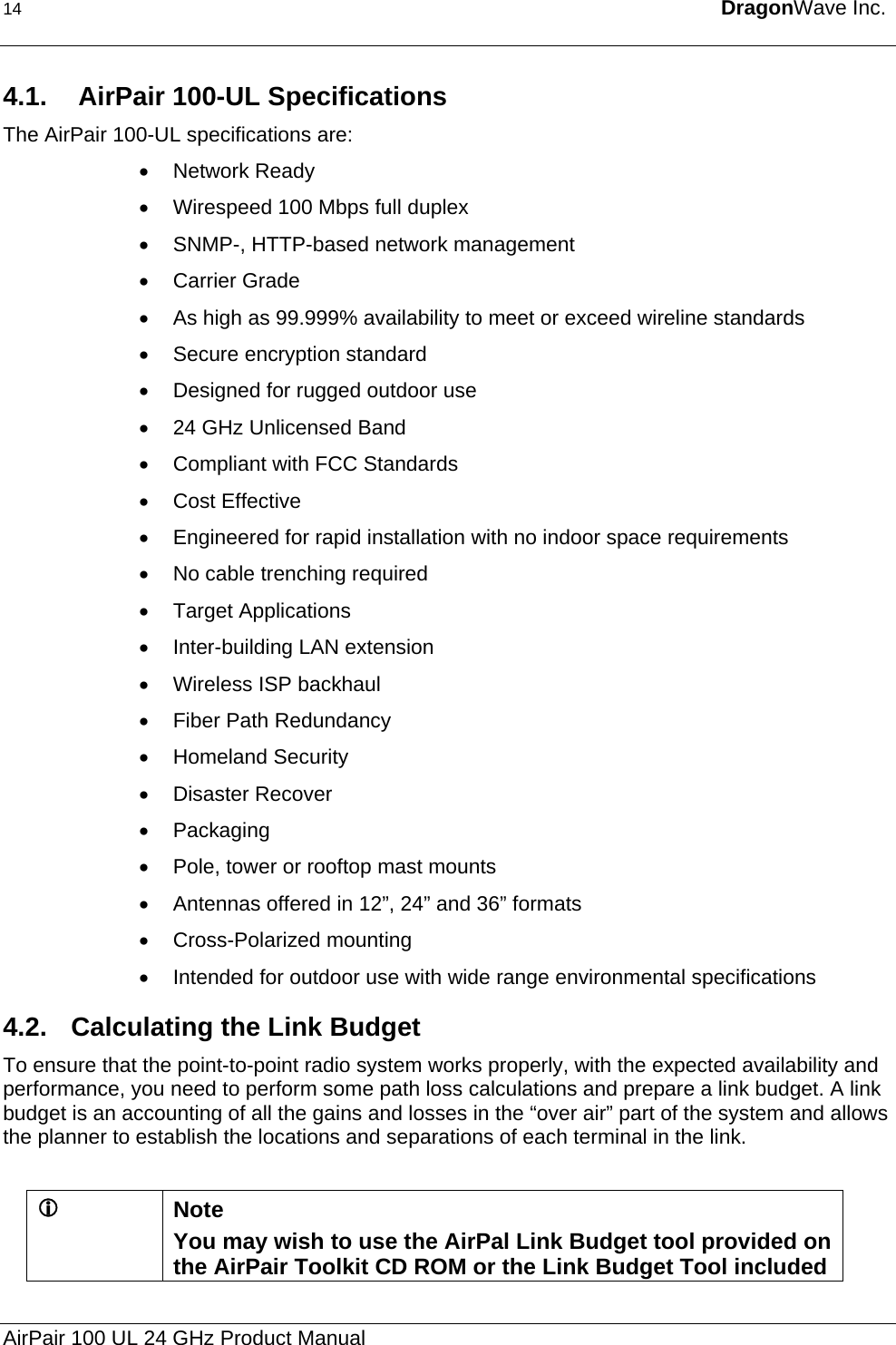
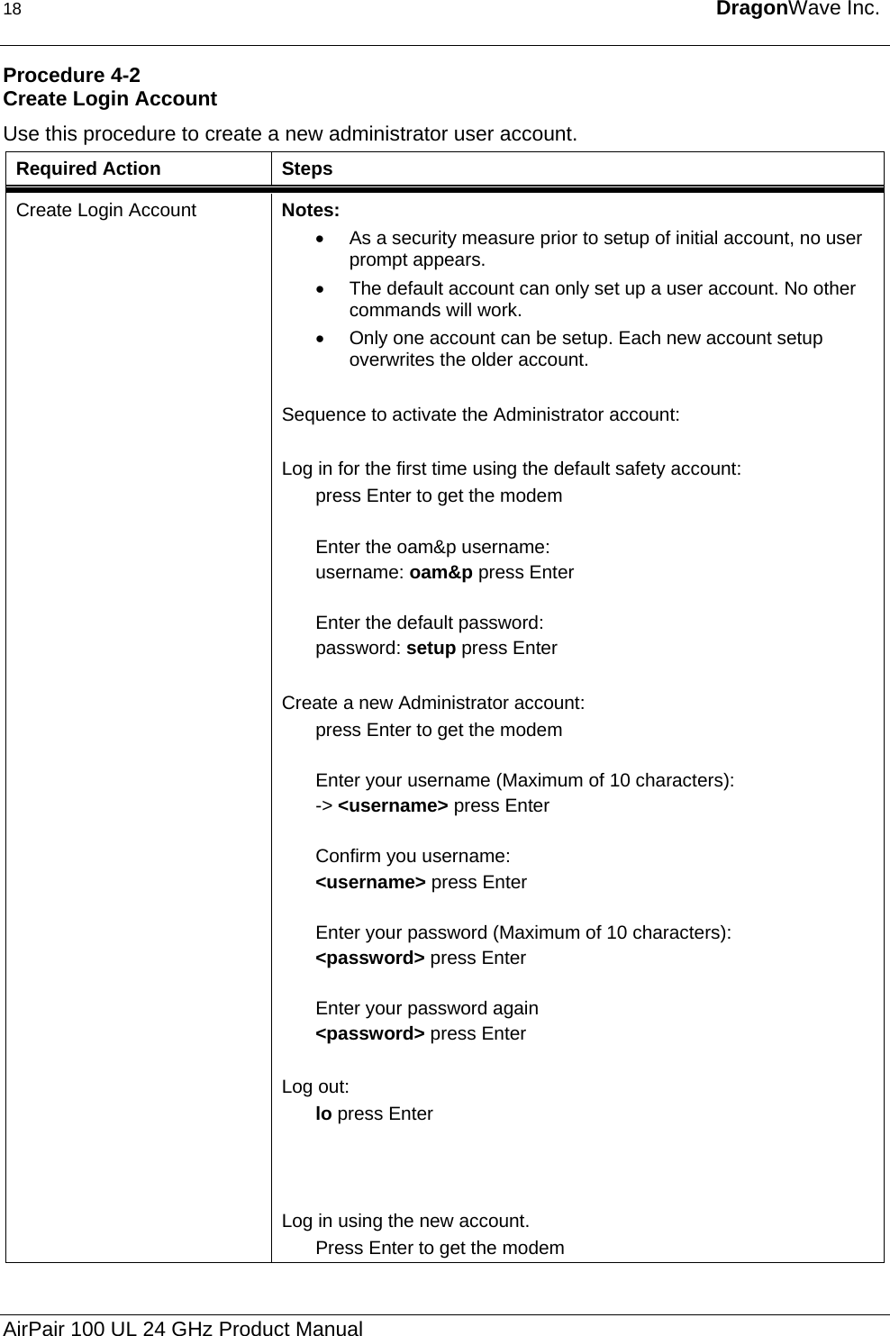
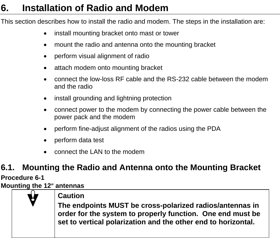
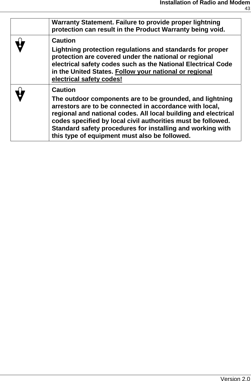
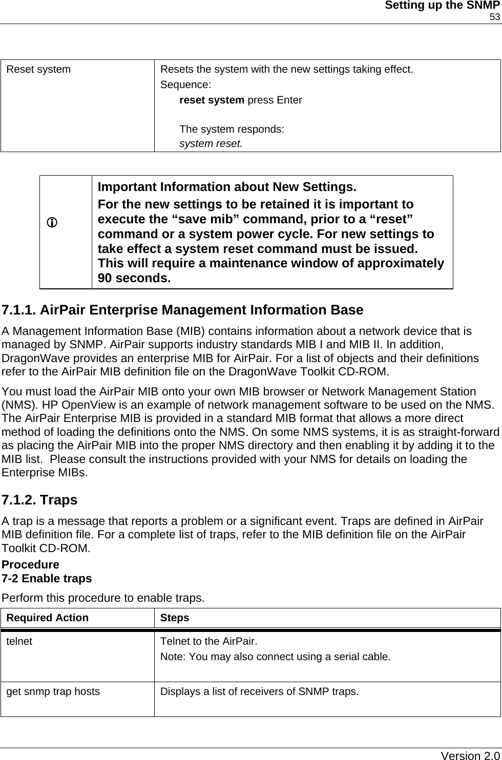
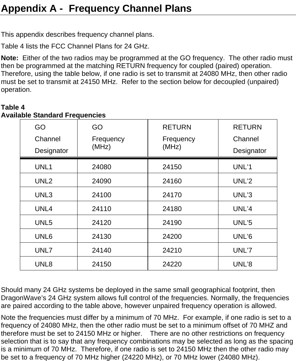
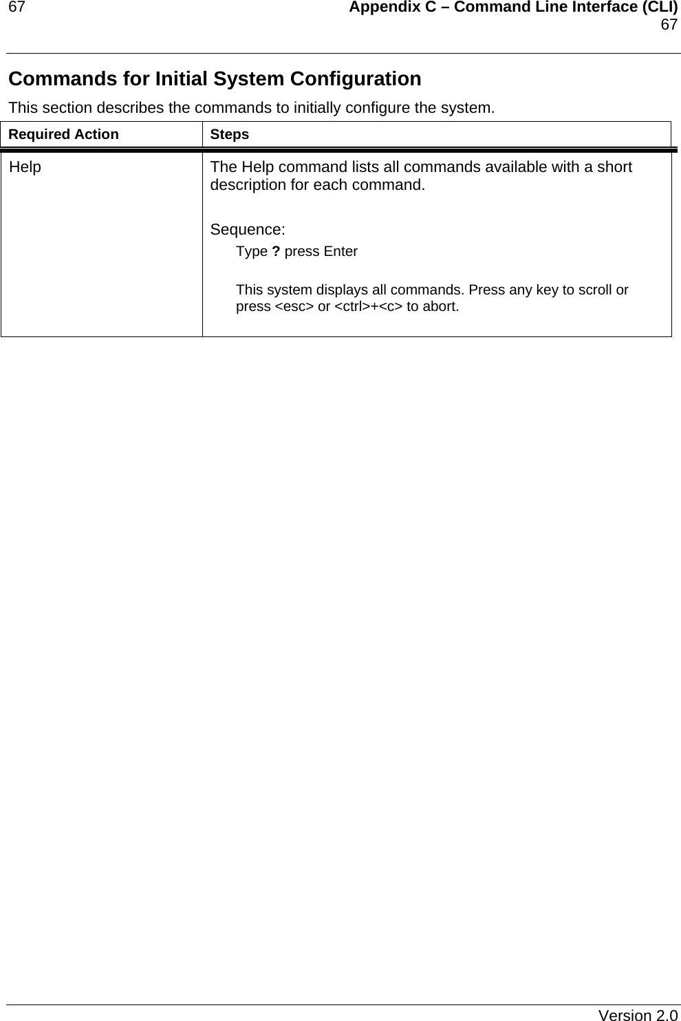
![Description 23 Required Action Steps get available frequency Displays the frequency bank. This will show the frequencies for the direction programmed using the set frequency bank command. If the frequency bank was selected to GO, then the GO bank of frequencies is displayed, and similarly the RETURN bank of frequencies is displayed if the RETURN frequency bank was selected. . Sequence: get available frequency press Enter The system responds: (“go” frequencies shown. “return” frequencies will be displayed if the return bank was programmed). go Frequencies Index TX IF RX IF TX RF RX RF UNL1 670 2000 24080 24150 UNL2 660 1990 24090 24160 UNL3 650 1980 24100 24170 UNL4 640 1970 24110 24180 UNL5 630 1960 24120 24190 UNL6 620 1950 24130 24200 UNL7 610 1940 24140 24210 UNL8 600 1930 24150 24220 Note: All Frequencies in MHz. set programmed frequency [frequency index] Sets the programmed frequency. Sequence: set programmed frequency [frequency index] press Enter The system responds: ( example uses set programmed frequency UNL1) Index TX IF RX IF TX RF RX RF UNL1 670 2000 24080 2415 Note: All Frequencies in MHz. get programmed frequency Displays the programmed frequency. Sequence: get programmed frequency press Enter The system responds: ( example uses set programmed frequency UNL1) Index TX IF RX IF TX RF RX RF UNL1 670 2000 24080 24150 Note: All Frequencies in MHz. Version 2.0](https://usermanual.wiki/DragonWave/DWR24-000002/User-Guide-399418-Page-31.png)
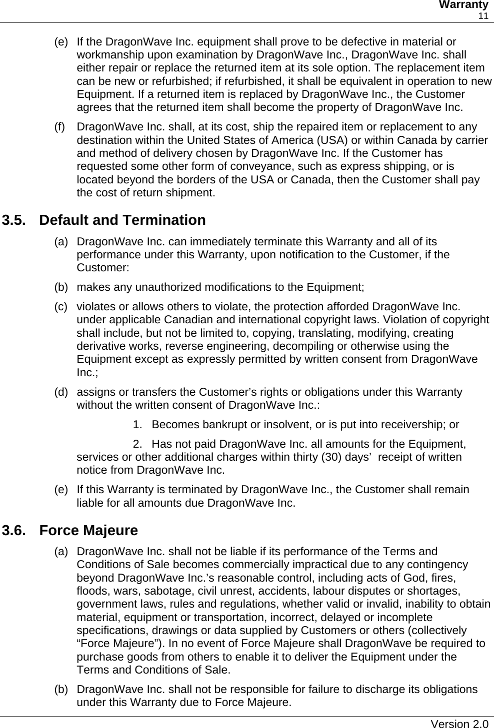
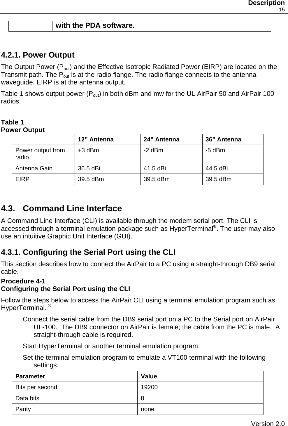
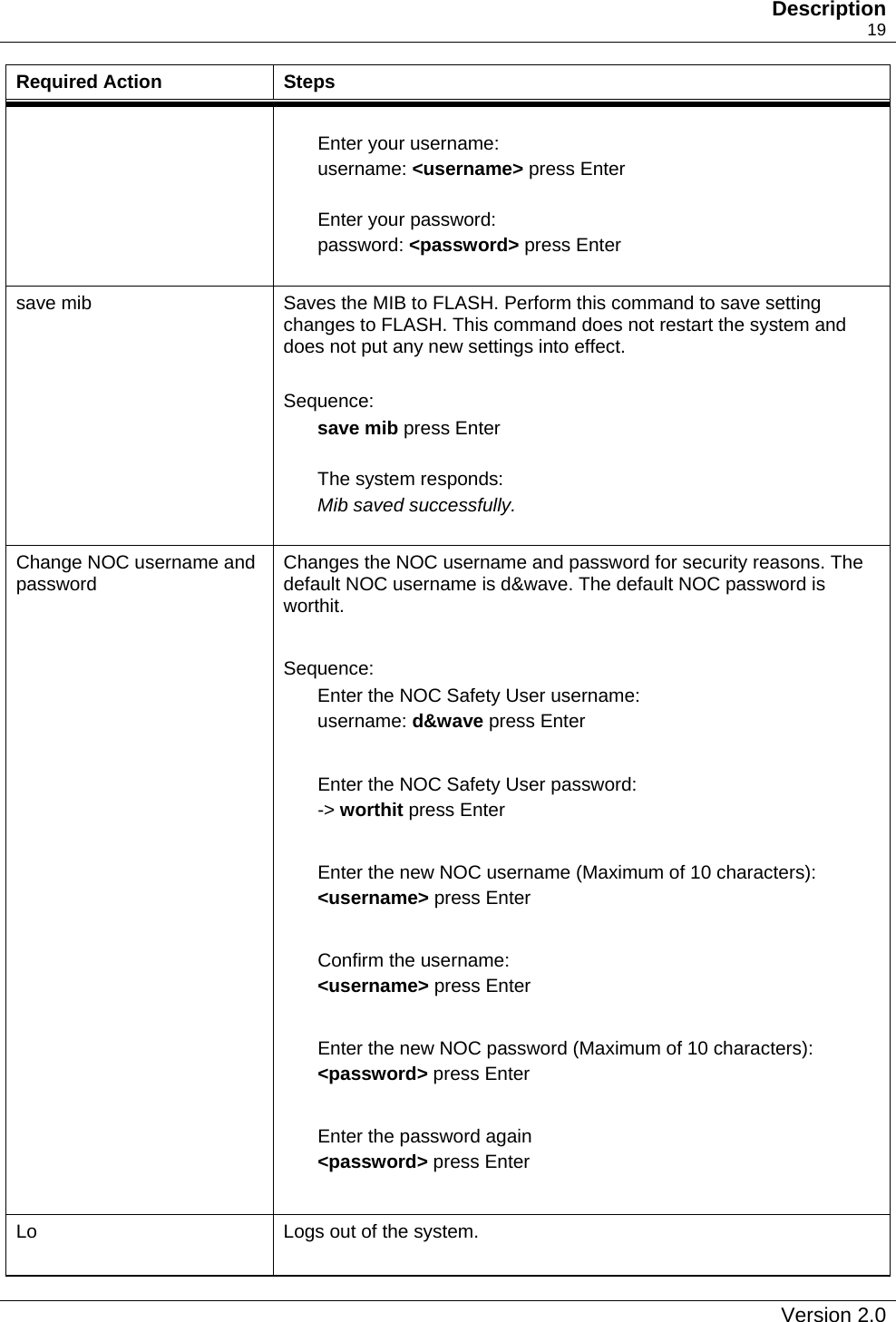
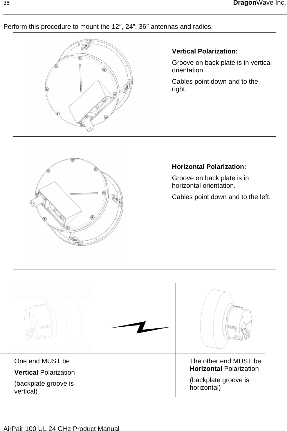
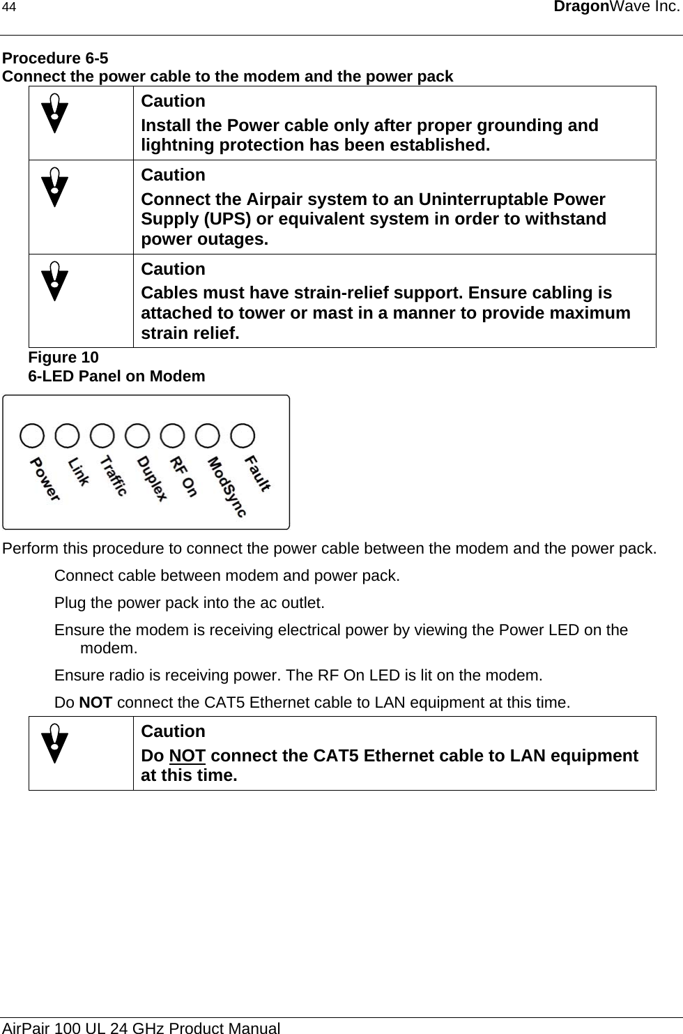
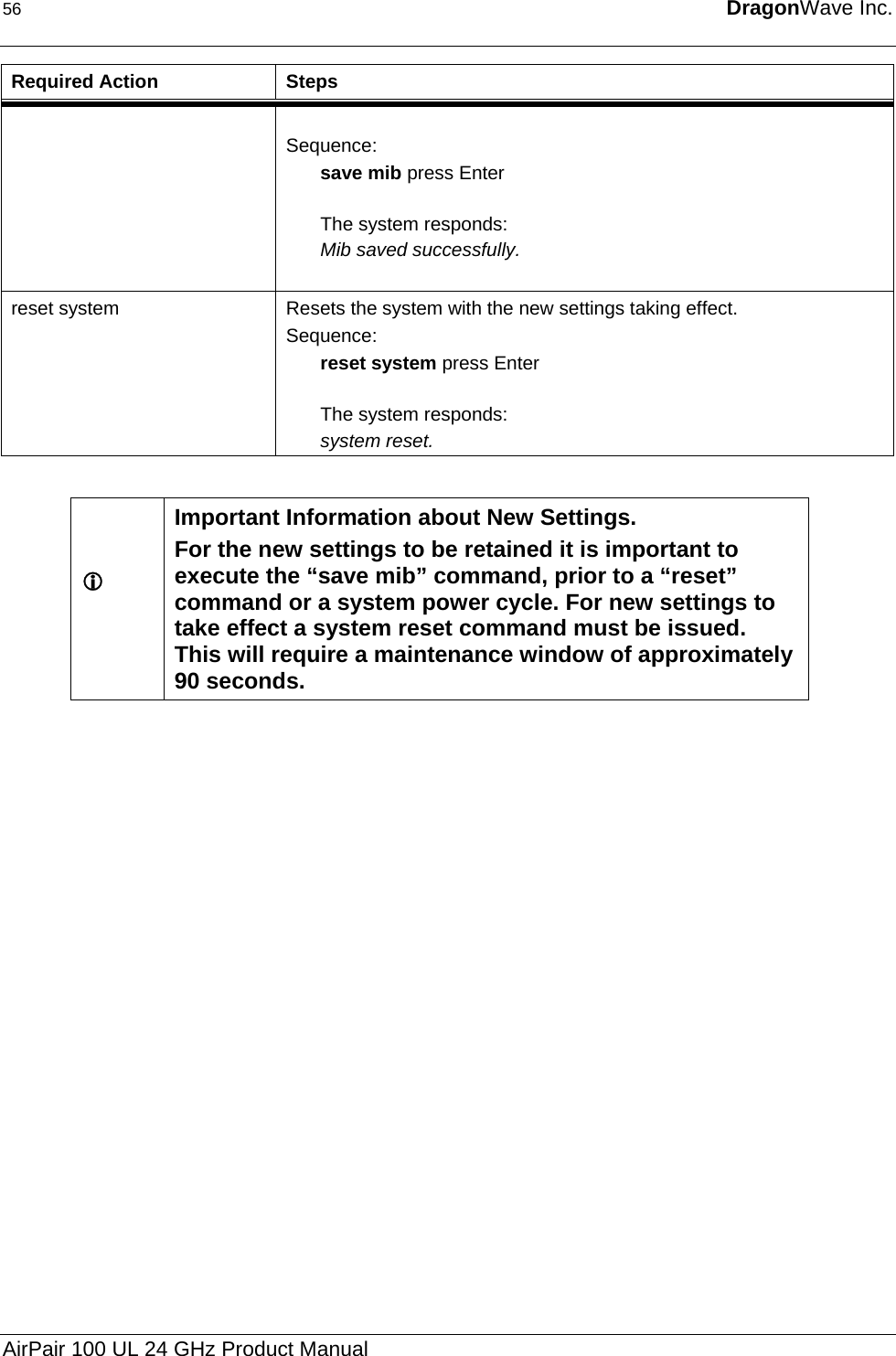
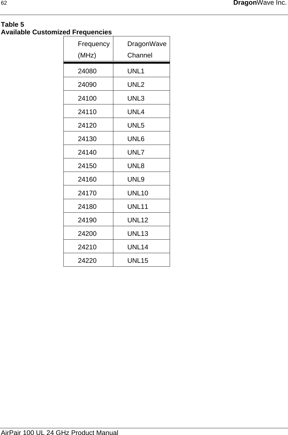
![24 DragonWave Inc. Required Action Steps get antenna diameter Displays the programmed antenna diameter. Sequence: get antenna diameter press Enter The system responds: Antenna Diameter: 12 inch 24 inch 36 inch - Programmed Note: The antenna diameter affects the radio Tx power for radio band un24 only. Set antenna diameter [index] Displays the programmed antenna size. Sequence: Set antenna diameter [index] press Enter where index is 1,2,3 The system responds: Programmed Antenna Diameter: [12 inch /24 inch /36 inch] Note: The antenna diameter affects the radio Tx power for radio band un24 only. AirPair 100 UL 24 GHz Product Manual](https://usermanual.wiki/DragonWave/DWR24-000002/User-Guide-399418-Page-32.png)
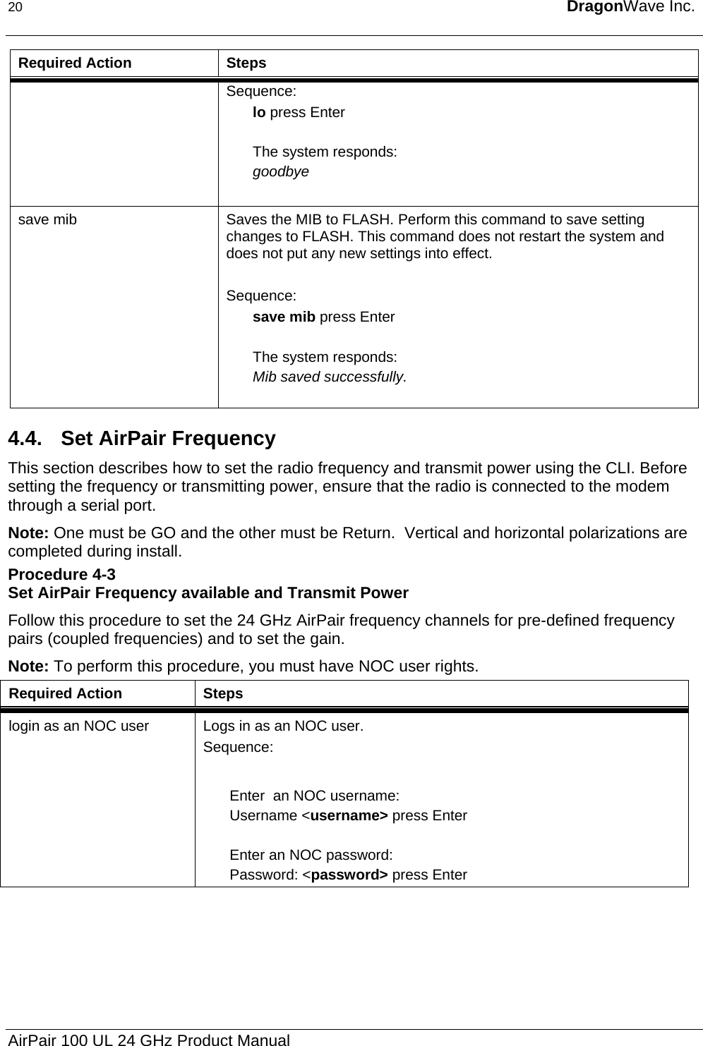
![Description 25 Required Action Steps set transmit power [power in dBm] Sets the transmit power level for the system, if required. Setting the antenna diameter programs the power to the maximum level allowed. Power will only be set to a maximum of +3, -2, or -5dBm based on the selected antennas size of either 12”, 24” or 36” respectively. Sequence: set transmit power [power in dBm] press Enter where [power in dBm] is a multiple of 10 value, i.e. 132 represents 13.2 dBm, 94 represents 9.4 dBm. The system responds: System is programmed and transmitting at [powerLevel] dBm. If the radio is not connected, the system responds: System programmed to [powerLevel] dBm. Radio communication has failed. System not transmitting. If the radio transmit calibration table is not programmed into the radio, the system responds: System programmed to [powerLevel] dBm. Note: Radio requires calibration tables in order to set the transmit power level. [powerLevel] dBm will NOT be used. save mib Saves the MIB to FLASH. Perform this command to save setting changes to FLASH. This command does not restart the system and does not put any new settings into effect. Sequence: save mib press Enter The system responds: Mib saved successfully. Version 2.0](https://usermanual.wiki/DragonWave/DWR24-000002/User-Guide-399418-Page-33.png)
![28 DragonWave Inc. Procedure 4-5 Setting the IP Address Perform this procedure to set the IP address for the system so you can access the AirPair from your desktop. Required Action Steps Login Log in as a NOC user. Only the NOC user is allowed to set the IP address. Sequence: Enter an NOC username: username: <username> press Enter Enter an NOC password: password: <password> press Enter set ip address Set the IP address used for the system. Sequence: set ip address [123.123.123.123] press Enter where [123.123.123.123] is in decimal dot notation. The system responds: System IP address: [123.123.123.123]] set subnet mask Sets the subnet mask used for the system. Sequence: set subnet mask [123.123.123.123] press Enter where [123.123.123.123] is in decimal dot notation. The system responds: System subnet mask:[123.123.123.123] set default gateway Sets the default gateway parameter for the system. The default router must be an IP address specified in decimal-dot notation, e.g., 192.168.0.1. Sequence: set default gateway [123.123.123.123] press Enter where [123.123.123.123] is in decimal dot notation. AirPair 100 UL 24 GHz Product Manual](https://usermanual.wiki/DragonWave/DWR24-000002/User-Guide-399418-Page-36.png)
![Description 31 Procedure 4-6 Setting VLAN Tag L Note If you set the VLAN tag to the incorrect value, you can lose remote access to the AirPair. Make sure the VLAN tag matches your administrative network tag. Perform this procedure to enable VLAN tagging for the AirPair. Note: To perform this procedure, you must have NOC user rights. Required Action Steps login Log in as an NOC user. Sequence: Enter an NOC username: username: <username> press Enter Enter an NOC password: password: <password> press Enter get vlan tagging Displays the VLAN tagging operational state for the system. Sequence: get vlan tagging press Enter The system responds: VLAN tagging is [off | on] set vlan tagging [on/off] Sets VLAN tagging on for the system. Sequence: set vlan tagging on press Enter The system responds: VLAN tagging is on. set vlan tag [8100XXXX] Enables or disables VLAN tagging for the system. VLAN tagging is enabled when you enter the hex characters 8100 immediately followed by the 2-byte tag control information field. Note: If you set the VLAN tag to the incorrect value, you can lose remote access to the AirPair. Make sure the VLAN tag matches your administrative network tag. Sequence: set vlan tag [8100XXXX] press Enter Version 2.0](https://usermanual.wiki/DragonWave/DWR24-000002/User-Guide-399418-Page-39.png)
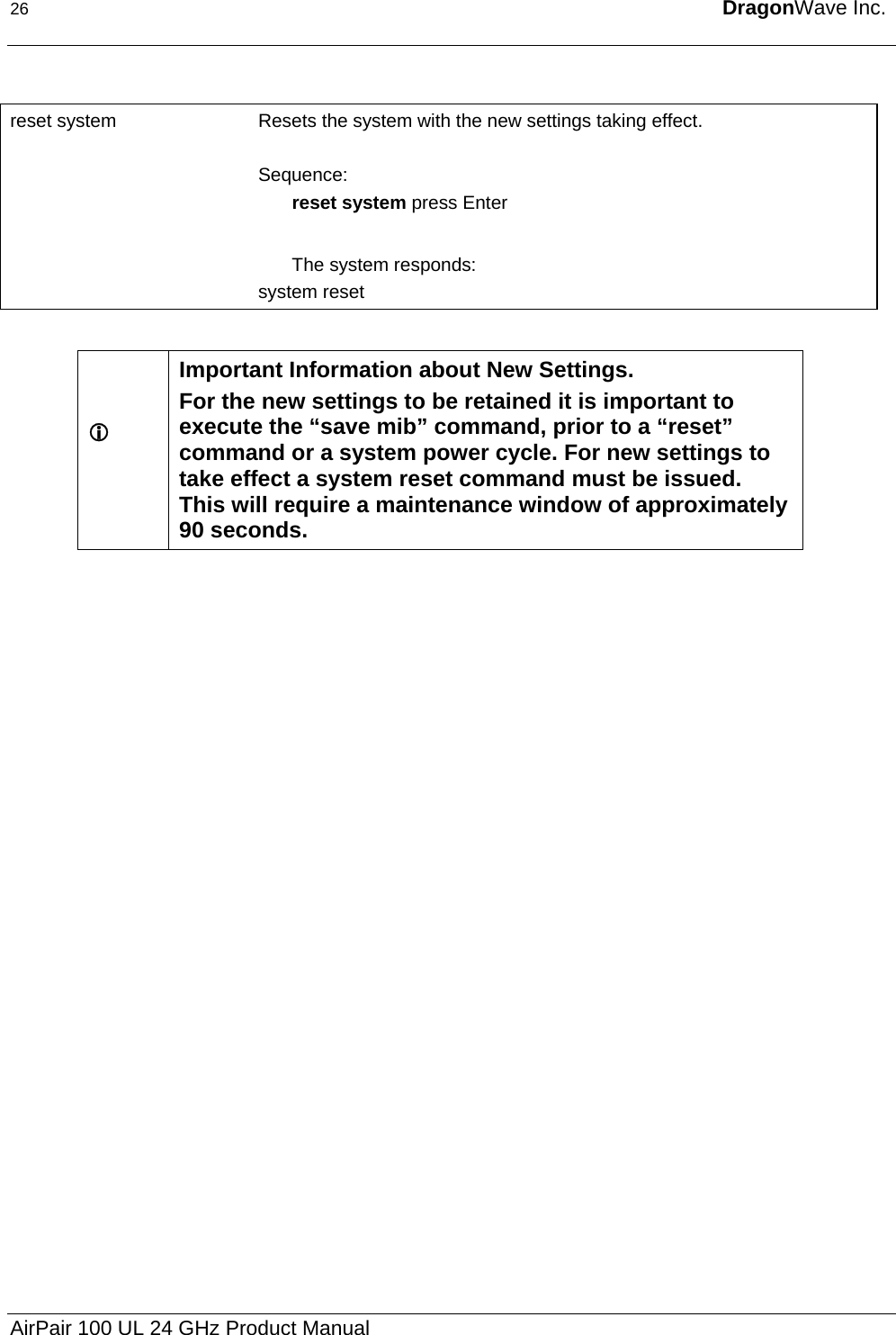
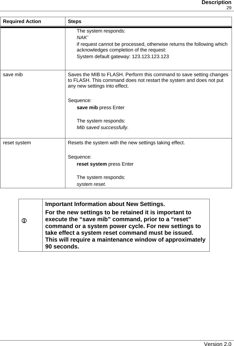
![32 DragonWave Inc. Required Action Steps where XXXX is the two byte tag control The system responds: VLAN tagging is [off | on using 8100XXXX] get vlan tag Displays that the VLAN tagging information for the system is correct. If you have entered an incorrect VLAN tag, you cannot communicate remotely with the AirPair. Sequence: get vlan tag press Enter The system responds: VLAN tagging is [off | on using tag 8100XXXX] save mib Saves the MIB to FLASH. Perform this command to save setting changes to FLASH. This command does not restart the system and does not put any new settings into effect. Sequence: save mib press Enter The system responds: Mib saved successfully. reset system Resets the system with the new settings taking effect. Sequence: reset system press Enter The system responds: system reset. L Important Information about New Settings. For the new settings to be retained it is important to execute the “save mib” command, prior to a “reset” command or a system power cycle. For new settings to take effect a system reset command must be issued. This will require a maintenance window of approximately 90 seconds. AirPair 100 UL 24 GHz Product Manual](https://usermanual.wiki/DragonWave/DWR24-000002/User-Guide-399418-Page-40.png)

![7. Setting up the SNMP Procedure 7-1 Setting up SNMP Perform this procedure to set up SNMP for the AirPair. Required Action Steps telnet Telnets to the AirPair. set snmp access mode [v1/v2c/off] Selects a mode. Sequence: set snmp access mode [v1/v2c/off] press Enter The system responds: SNMP Mode: [v1 | v2c | off] set snmp set request [on/off] Sets the SNMP access on. This allows SNMP v1 and v2c ‘Set’ requests. Sequence: set snmp set request [on/off] press Enter The system responds: SNMP Set Requests are [on/off]. get snmp set request Displays SNMP requests on. Shows if SNMP v1 and v2c ‘Set’ requests are enabled. The default is off. Sequence: get snmp set requests press Enter The system responds: SNMP Set Requests are [on | off]. get snmp managers Displays a list of managers that can access the system via SNMP. Sequence: get snmp managers press Enter The system responds: Mgr # IpAddress/ CommunityString 1 192.168.1.133 example text1](https://usermanual.wiki/DragonWave/DWR24-000002/User-Guide-399418-Page-59.png)
![52 DragonWave Inc. Required Action Steps 2 192.168.1.100 example text2 If there are no managers specified, the system responds: No managers configured for the system. set snmp manager [mgr#] [ip address] [enable/disable] [community string] Specifies the SNMP managers to allow access to the system. Sequence: set snmp manager [mgr#] [ip address] [enable/disable] [community string] press Enter The system responds: Mgr# IpAddress Status CommunityString 1 192.7.1.1 disabled public 2 0.0.0.0 disabled public 3 0.0.0.0 disabled public 4 0.0.0.0 disabled public 5 0.0.0.0 disabled public 6 any disabled public Note 1: Only maximum of 5 managers are allowed. If all the managers are filled in, remove 1 manager by overwriting the particular index. Note 2: By setting the IP address of last index to 'any' and 'enable', anybody can have access to the system via SNMP. set SysContact Sets System contact to allow access MIB objects via an SNMP browser. For example, you can set the sysContact in MIB-II (RFC 1213) using your MIB browser, e.g., HP OpenView Node Manager. save mib Saves the MIB to FLASH. Perform this command to save setting changes to FLASH. This command does not restart the system and does not put any new settings into effect. Sequence: save mib press Enter The system responds: Mib saved successfully. AirPair 100 UL 24 GHz Product Manual](https://usermanual.wiki/DragonWave/DWR24-000002/User-Guide-399418-Page-60.png)
![54 DragonWave Inc. Required Action Steps Sequence: get snmp trap hosts press Enter The system responds: Host# IpAddress Status CommunityString 1 0.0.0.0 disabled public 2 0.0.0.0 disabled public 3 0.0.0.0 disabled public 4 0.0.0.0 disabled public 5 0.0.0.0 disabled public Note: A maximum of 5 hosts is allowed. If all the hosts are filled in, remove 1 host by overwriting the particular index. set snmp trap host [host #] [ipAddress] [enable/disable] [communityString] Adds an SNMP trap host to the list of receivers of SNMP traps. Specify the IP address where the system sends traps. Sequence: set snmp trap host [host #] [ipAddress] [enable/disable] [communityString] press Enter The system responds: Host# IpAddress Status CommunityString 1 0.0.0.0 disabled public 2 0.0.0.0 disabled public 3 3.3.3.3 enabled new text string here 4 0.0.0.0 disabled public 5 0.0.0.0 disabled public Note: A maximum of 5 hosts are allowed. If all the hosts are filled in, remove 1 host by overwriting the particular index. get snmp traps Displays the list of traps that are available in the system. Sequence: get snmp traps press Enter The system responds: Trap# TrapName Enabled(Yes | No) 1 ColdStart No 2 WarmStart No 3 Link down No 4 Link up No 5 Explicit Authentication Failure No AirPair 100 UL 24 GHz Product Manual](https://usermanual.wiki/DragonWave/DWR24-000002/User-Guide-399418-Page-62.png)
![Setting up the SNMP 55 Required Action Steps 6 AutoNeg Mismatched Duplex No 7 LossOfSignalLockFromDemod No 8 BerThresholdExceeded No 9 Mod PLL lock failure No 10 Mod loss of sync bytes No 11 Mod input FIFO overrun/underrun No 12 Mod input data inactivity No 13 SNR below threshold No 14 PLDRO lost lock No 15 Radio lost comm No 16 Radio mismatch No 17 IF Tx Synth Unlocked No 18 IF Rx Synth Unlocked No set snmp trap [trapIndex] [enable/disable] Sets the SNMP trap and enables or disables it. DragonWave recommends enabling the LossOfSignalLockFromDemod trap. This trap indicates loss of communication with the peer AirPair node. Sequence: set snmp trap [trapIndex] [enable/disable] press Enter The system responds: Trap# TrapName Enabled(Yes | No) 1 ColdStart No 2 WarmStart No 3 Link down No 4 Link up No 5 Explicit Authentication Failure No 6 AutoNeg Mismatched Duplex No 7 LossOfSignalLockFromDemod No 8 BerThresholdExceeded No 9 Mod PLL lock failure No 10 Mod loss of sync bytes No 11 Mod input FIFO overrun/underrun No 12 Mod input data inactivity No 13 SNR below threshold No 14 PLDRO lost lock No 15 Radio lost comm No 16 Radio mismatch No 17 IF Tx Synth Unlocked No 18 IF Rx Synth Unlocked No save mib Saves the MIB to FLASH. Perform this command to save setting changes to FLASH. This command does not restart the system and does not put any new settings into effect. Version 2.0](https://usermanual.wiki/DragonWave/DWR24-000002/User-Guide-399418-Page-63.png)


![70 DragonWave get radio band Retrieves the type (band) of radio that the user expects to connect to the modem. Sequence: get radio band press Enter The system responds: Currently selected Radio Band :[none/fcc18a/fcc18b/fcc18c/ ic18a/ic18b/ic18c/fcc23a/fcc23b/fcc23c/fcc23d/ic23a/ic23b/ fcc28a/fcc28b/china23/un24/etsi23a_28/etsi23a_56/ etsi26b_28/etsi26b_56] Radio Bands Available in the system : none fcc18a fcc18b fcc18c ic18a ic18b ic18c fcc23a fcc23b fcc23c fcc23d ic23a ic23b fcc28a fcc28b china23 un24 etsi23a_28 etsi23a_56 etsi26b_28 etsi26b_56 FCC = United States Federal Communications Commission IC = Industry Canada China = China ETSI = European Telecommunications Standards Institute UN = Unlicensed AirPair 100 UL 24 GHz Product Manual](https://usermanual.wiki/DragonWave/DWR24-000002/User-Guide-399418-Page-78.png)
![71 Appendix C – Command Line Interface (CLI) 71 set radio band [none/fcc18a/fcc18b/fcc18c/ ic18a/ic18b/ic18c/fcc23a/fcc23b/fcc23c/fcc23d/ic23a/ic23b/ fcc28a/fcc28b/china23/un24/etsi23a_28/etsi23a_56/ etsi26b_28/etsi26b_56] Sets the band of radio that the user expects to connect to the modem. Sequence: set radio band [band] press Enter where band is none/fcc18a/fcc18b/fcc18c/ ic18a/ic18b/ic18c/fcc23a/fcc23b/fcc23c/fcc23d/ic23a/ic23b/ fcc28a/fcc28b/china23/un24/etsi23a_28/etsi23a_56/ etsi26b_28/etsi26b_56 The system responds: Currently selected Radio Band :[none/fcc18a/fcc18b/fcc18c/ ic18a/ic18b/ic18c/fcc23a/fcc23b/fcc23c/fcc23d/ic23a/ic23b/ fcc28a/fcc28b/china23/un24/etsi23a_28/etsi23a_56/ etsi26b_28/etsi26b_56] Radio Bands Available in the system : none fcc18a fcc18b fcc18c ic18a ic18b ic18c fcc23a fcc23b fcc23c fcc23d ic23a ic23b fcc28a fcc28b china23 un24 etsi23a_28 etsi23a_56 etsi26b_28 etsi26b_56 Version 2.0](https://usermanual.wiki/DragonWave/DWR24-000002/User-Guide-399418-Page-79.png)
![72 DragonWave get frequency bank Displays the frequency bank. Sequence: get frequency bank press Enter The system responds un24 go FREQUENCIES Index TX IF RX IF TX RF RX RF Status UNL1 670 1610 24080 24150 Y UNL2 660 1600 24090 24160 Y UNL3 650 1590 24100 24170 Y UNL4 640 1580 24110 24180 Y UNL5 630 1570 24120 24190 Y UNL6 620 1560 24130 24200 Y UNL7 610 1550 24140 24210 Y UNL8 600 1540 24150 24220 Y return FREQUENCIES(Selected) Index TX IF RX IF TX RF RX RF Status UNL'1 600 1680 24150 24080 Y UNL'2 590 1670 24160 24090 Y UNL'3 580 1660 24170 24100 Y UNL'4 570 1650 24180 24110 Y UNL'5 560 1640 24190 24120 Y UNL'6 550 1630 24200 24130 Y UNL'7 540 1620 24210 24140 Y UNL'8 530 1610 24220 24150 Y All Frequency in MHz set frequency bank Selects the transmit frequency bank [go/return]. Sequence: set frequency bank [go/return] press Enter The system responds: [go/return] frequency bank selected. AirPair 100 UL 24 GHz Product Manual](https://usermanual.wiki/DragonWave/DWR24-000002/User-Guide-399418-Page-80.png)
![73 Appendix C – Command Line Interface (CLI) 73 set available frequency [frequency index] Sets the available frequency. This is an NOC level command. set available frequency [frequency index] press Enter The system responds (Example: FCC18A): Index RF Frequency (MHz) Available(Y/N)? A txlow Frequencies Index TX IF RX IF TX RF RX RF Status 1 590 1110 17720 19280 N 2 550 1150 17760 19320 N 3 510 1190 17800 19360 N 4 470 1230 17840 19400 Y 5 430 1270 17880 19440 N set programmed frequency [frequency index] Sets the programmed frequency. Sequence: set programmed frequency [frequency index] press Enter where [frequency index] must be an enabled frequency The system responds (Example: FCC18A): Index TX IF RX IF TX RF RX RF 4 470 1230 17840 19400 All Frequency in MHz Version 2.0](https://usermanual.wiki/DragonWave/DWR24-000002/User-Guide-399418-Page-81.png)
![74 DragonWave set transmit power [power in dbm] Sets the transmit power level for the system, if required. Setting the antenna diameter programs the power to the maximum level allowed. Power will only be set to a maximum of +3, -2, or -5dBm based on the selected antennas size of either 12”, 24” or 36” respectively Sequence: set transmit power [power in dbm] press Enter where [power in dbm] is a multiple of 10 value i.e. 132 represents 13.2dBm, 94 represents 9.4dBm. The system responds: System is programmed and transmitting at [powerLevel] dBm. If the radio is not connected, the system responds: System programmed to [powerLevel] dBm. Radio communication has failed. System not transmitting. If the radio transmit calibration table is not programmed into the radio, the system responds: System programmed to [powerLevel] dBm. Radio requires calibration tables in order to set the transmit power level. [powerLevel] dBm will NOT be used. save mib Saves the MIB to RAM. Perform this command save setting changes. This command does not restart the system and does not put any new settings into effect. A system reset command is required to cause settings in RAM to be programmed into FLASH and to take effect. Sequence: save mib press Enter The system responds: MIB saved successfully. AirPair 100 UL 24 GHz Product Manual](https://usermanual.wiki/DragonWave/DWR24-000002/User-Guide-399418-Page-82.png)
![75 Appendix C – Command Line Interface (CLI) 75 reset system Resets the system to save the settings to FLASH and restart the system with the new settings taking effect. Sequence: reset system press Enter The system responds: system reset. get leds Displays the system LEDS with their ON/OFF values. Sequence: get leds press Enter The system responds: Ethernet Link Status LED : [on | off] Ethernet Traffic LED : [on | off] Ethernet Full Duplex Mode LED : [on | off] System Trouble LED : [on | off] Power LED : [on | off] modem Sync LED : [on | off] RF On LED : [on | off] Antenna Alignment : [0 – 100] % Note: The value of the multi-segment antenna alignment LED is given in percent. Version 2.0](https://usermanual.wiki/DragonWave/DWR24-000002/User-Guide-399418-Page-83.png)
![76 DragonWave Command Syntax Summary ? (help) copy [ftp:fileName] delete mib [newest|both] exit get alarms get air interface authentication type get airpair type get antenna diameter get auto negotiation get authentication failure action get authenticated peer get authentication status get available frequency get backup ipconfig get date time get default ipconfig get default gateway get enet address get frequency bank get group authentication key get health get hw revision get if status get if statistics get ip address get leds get modem card modulation get modem statistics get negotiated link parameters get network protocol strict get omni file crc get omni file version AirPair 100 UL 24 GHz Product Manual](https://usermanual.wiki/DragonWave/DWR24-000002/User-Guide-399418-Page-84.png)
![77 Appendix C – Command Line Interface (CLI) 77 get programmed frequency get radio band get radio gain get radio serial number get radio transmitter state get radio statistics get transmit power get serial number get sessions get snmp access mode get snmp managers get snmp set request get snmp traps get snmp trap hosts get snr threshold get subnet mask get telnet access get traffic statistics get unique peer authentication key get version get vlan tag get vlan tagging list [ftp:file/directory/empty] lo ping [-w timeout][-n count][-t] abc.def.ghi.jkl reset [resource id] save mib set air interface authentication type [authentication type] set authentication failure [action] set airpair type [airpair50|airpair100|airpairOC3|airpair100SDR] set antenna diameter [index of diameter] set auto negotiation [on|off] set date time [dd/mm/yyyy hh:mm:ss:ms] set default gateway [abc.def.ghi.jkl] Version 2.0](https://usermanual.wiki/DragonWave/DWR24-000002/User-Guide-399418-Page-85.png)
![78 DragonWave set frequency bank [go|return] set group authentication key [key] set network protocol strict [on/off] set programmed frequency [IndexID] set radio transmitter state [transmitter state] set radio band set radio rxgain [gain] set traffic statistics [0] set telnet [on|off] set snmp access mode [v1|v2c|off] set snmp manager [Mgr Index] [ipAddress] [enable|disable] [communityString] set snmp set request [on|off] set snmp trap [trap#] [enable|disable] set snmp trap host [host#] [ipAddress] [enable|disable] [communityString] set transmit power [powerLevel] set user set unique peer authentication key [key] set ip address [abc.def.ghi.jkl] set subnet mask [abc.def.ghi.jkl] set vlan tagging [on|off] set vlan tag [vlan ID(0 - 4095)] [vlan priority(0 - 7)] upgrade to airpair100 [system key] AirPair 100 UL 24 GHz Product Manual](https://usermanual.wiki/DragonWave/DWR24-000002/User-Guide-399418-Page-86.png)
![79 Appendix C – Command Line Interface (CLI) 79 Complete List of CLI Commands This section shows a complete list of CLI commands. This document uses the following conventions to describe commands: • <filename> or [newoldboth] - replace bolded information in brackets with the correct entry • message — system responses and messages are shown in italics • press Enter – instructs you to press the Enter key on your keyboard. • NAK – system response indicating that the system cannot process the request. Repeat the action. There are three keying features that simplify typing the commands. These features are: • tab key - When you type the first few characters of a unique command you can press the tab key and the system fills in the rest of the command if there is a unique matching command. For example, when you type “get authentication s”, press tab and the system automatically fills in the rest of the “get authentication status” command. • Enter key – To execute a command, press Enter. • <esc> key – To abort a command, press the <esc> key. • <ctrl>+c – To abort a command, press the <ctrl>+c. • arrow keys – Use the arrow keys at the command line interface to scroll through the previous 20 issued commands. Version 2.0](https://usermanual.wiki/DragonWave/DWR24-000002/User-Guide-399418-Page-87.png)
![82 DragonWave Command Steps delete mib [newest/both] Deletes the MIB. If you delete the newest MIB, then the old becomes the active MIB. If you delete both MIBs, the default MIB is created on system startup. There are two copies of the MIB in FLASH. Note: Do not delete both MIBs. The MIBs contain all system settings, e.g., frequency, SNMP settings. If you delete both MIBs, the AirPair loses communication. Sequence: Type delete mib <newest/both> press Enter The system responds: Delete MIB [Newest/Both]? To delete both MIBs: Type Y press Enter To cancel the delete action: Enter N press Enter The system responds: Are you absolutely sure? Enter Y (yes) or N (no): To delete the MIBs: Enter Y press Enter To cancel the delete action: Enter N press Enter Note: The system does not allow you to enter any commands until the MIB has been deleted, or has failed to delete. When the system successfully completes the command, it displays the message: Delete [Newest/Both] MIB [OK/Failed/Cancelled] AirPair 100 UL 24 GHz Product Manual](https://usermanual.wiki/DragonWave/DWR24-000002/User-Guide-399418-Page-90.png)
![84 DragonWave Command Steps get air interface authentication type Displays the authentication type used on the air interface. Sequence: get air interface authentication type press Enter where authentication type is one of the following: none unique group The system responds: air interface authentication type set to [authentication type] get airpair type Displays the type of AirPair that the system is, either an AirPair 50 or AirPair 100. Sequence: get airpair type press Enter The system responds: Your system is an [AirPair50 | AirPair100] get antenna diameter Displays the programmed antenna diameter. Sequence: get antenna diameter press Enter The system responds: Antenna Diameter: 12 inch 24 inch 36 inch - Programmed Note: The antenna diameter affects the radio Tx power for radio band un24 only. AirPair 100 UL 24 GHz Product Manual](https://usermanual.wiki/DragonWave/DWR24-000002/User-Guide-399418-Page-92.png)
![85 Appendix C – Command Line Interface (CLI) 85 Command Steps get auto negotiation Displays the 100BaseT interface auto-negotiation parameters. Sequence: get auto negotiation press Enter If the auto-negotiation is disabled, the system responds Auto-negotiation disabled. Defaulting to 100BASE-T Full duplex If auto-negotiation is enabled and auto-negotiation has not failed, the system responds: Auto-negotiation enabled, 100BASE-T Full duplex. If auto-negotiation is enabled and auto-negotiation has failed, the system responds: Auto-negotiation enabled, failed. System operating at 100BASE-T [Full|Half] duplex. Note: The [Full|Half] indicator will be either Full or Half, based on the negotiated link results. get authenticated peer Unique Mode: Displays the serial number of the system that this AirPair is communicating with only if authentication occurs. Group Mode Displays the group Authentication Key of the system that this AirPair is communicating with only if authentication occurs. Sequence: get authenticated peer press Enter The system responds: Detected peerAuthenticationKey: [see text above] Version 2.0](https://usermanual.wiki/DragonWave/DWR24-000002/User-Guide-399418-Page-93.png)
![86 DragonWave Command Steps get authentication failure action Displays action on authentication failure. Sequence: get authentication failure action press Enter The system responds: System will [action] on peer authentication failure. where [action] is block_traffic or pass_traffic. get authentication status Displays the Authentication status. Sequence: get authentication status press Enter Where [Authentication Status] is one of the following: Authenticated NotAuthenticated ExplicitAuthenticationFailure The system responds: Authentication status: [Authentication Status] AirPair 100 UL 24 GHz Product Manual](https://usermanual.wiki/DragonWave/DWR24-000002/User-Guide-399418-Page-94.png)
![88 DragonWave Command Steps get date time Displays the date and time. Sequence: get date time press Enter Where dd = day of month (range 01 to 31) MM = month (range 01 to 12) yy = year (range 01 – 99) HH = hour of day ( range 00 to 23 ) mm = minute of hour( range 00 to 59 ) ss = second of minute( range 00 to 59 ) dd = millisecond of second( range 000 to 999 ) The system responds: date time dd/MM/yy HH:mm:ss:dd get default ipconfig Displays the default IP configuration. The system uses the default IP configuration and subnet masks when you have not saved your unique IP address. DragonWave ships the AirPair with this IP configuration. Sequence: get default ipconfig press Enter The system responds: Default IP Configuration IP Address :192.168.10.100 Subnet Mask :255.255.0.0 get default gateway Displays the system's default gateway parameter. Sequence: get default gateway press Enter The system responds: NAK’ If request cannot be processed, otherwise returns the following which acknowledges completion of the request: System default gateway: 123.123.123.123 where [123.123.123.123] is in decimal-dot notation. AirPair 100 UL 24 GHz Product Manual](https://usermanual.wiki/DragonWave/DWR24-000002/User-Guide-399418-Page-96.png)
![89 Appendix C – Command Line Interface (CLI) 89 Command Steps get enet address Displays the Ethernet address for the system. Sequence: get enet address press Enter The system responds: System Ethernet address: [0xab 0xcd 0xef 0xgh 0xij 0xkl]. Where [0xab 0xcd 0xef 0xgh 0xij 0xkl] is in hex notation. Version 2.0](https://usermanual.wiki/DragonWave/DWR24-000002/User-Guide-399418-Page-97.png)
![90 DragonWave Command Steps get frequency bank Displays the frequency bank. Sequence: get frequency bank press Enter The system responds: un24 go FREQUENCIES(Selected) Index TX IF RX IF TX RF RX RF UNL1 670 2000 24080 24150 UNL2 660 1990 24090 24160 UNL3 650 1980 24100 24170 UNL4 640 1970 24110 24180 UNL5 630 1960 24120 24190 UNL6 620 1950 24130 24200 UNL7 610 1940 24140 24210 UNL8 600 1930 24150 24220 return FREQUENCIES Index TX IF RX IF TX RF RX RF UNL'1 600 2070 24150 24080 UNL'2 590 1990 24160 24090 UNL'3 580 2050 24170 24100 UNL'4 570 2040 24180 24110 UNL'5 560 2030 24190 24120 UNL'6 550 2020 24200 24130 UNL'7 540 2010 24210 24140 UNL'8 530 2000 24220 24150 Note: All Frequencies in MHz. get group authentication key Displays a listing of all group authentication keys. Sequence: get group authentication key press Enter The system responds: group key authentication set to [key] AirPair 100 UL 24 GHz Product Manual](https://usermanual.wiki/DragonWave/DWR24-000002/User-Guide-399418-Page-98.png)
![91 Appendix C – Command Line Interface (CLI) 91 Command Steps Get health Displays the operational condition of resources in the system. Sequence: get health press Enter The system responds: --Interface Card: [Operational | Not Operational] --modem Card: [Operational | Not Operational] --Radio: [Operational | Not Operational] Get hw revision Displays the hardware revisions in the system in the following format: Sequence: get hw revision press Enter The system responds: card | revision Interface | A.BC modem | A.BC IF | A.BC Radio | A.BC Note: A.BC is an alphanumeric string. Version 2.0](https://usermanual.wiki/DragonWave/DWR24-000002/User-Guide-399418-Page-99.png)
![92 DragonWave Command Steps get if status Displays the Transmit (Tx) and Receive (Rx) IF synthesizer lock status. Sequence: get if status press Enter Where [lock status] is locked or unlocked The system responds: IF Txsynthesizer currently [lock status] IF Rx synthesizer currently [lock status] get if statistics Show the IF statistics. Sequence: get if statistics press Enter The system responds: modem IF statistics: modem IF Rx Power: –n dBm Note: IF Power displayed is multiples of 10. For Ex, 132 dBm implies 13.2 dBm. get ip address Displays the IP address for the system. Sequence: get ip address press Enter The system responds: System IP address: [123.123.123.123]. Note: [123.123.123.123] is in decimal dot notation. AirPair 100 UL 24 GHz Product Manual](https://usermanual.wiki/DragonWave/DWR24-000002/User-Guide-399418-Page-100.png)
![93 Appendix C – Command Line Interface (CLI) 93 Command Steps get leds Displays the system LEDS with their ON/OFF values. Sequence: get leds press Enter The system responds: Ethernet Link Status LED : [on | off] Ethernet Traffic LED : [on | off] Ethernet Full Duplex Mode LED : [on | off] System Trouble LED : [on | off] Power LED : [on | off] modem Sync LED : [on | off] RF On LED : [on | off] Antenna Alignment : [0 – 100] % get modem card modulation Displays the modem modulation type. Sequence: get modem card modulation press Enter The system responds: modem modulation type [modulation type] Note: [modulation type] is one of the following: QPSK QAM QAM16 QAM32 QAM64 QAM128 QAM256 Version 2.0](https://usermanual.wiki/DragonWave/DWR24-000002/User-Guide-399418-Page-101.png)
![94 DragonWave Command Steps get modem statistics Displays modem statistics in the system. Sequence: get modem statistics press Enter The system responds: --modem Performance Statistics: BER [BER value] Eb/No [Eb/No ratio] dB RSL [RSL value] Equalizer Stress [Stress value] % get negotiated link parameters Displays the Negotiated Link Parameters. Sequence: get negotiated link parameters press Enter The system responds: Network Interface operational at [link param] Note: [link param] is one of the following: 100BaseT_FullDuplex 100BaseT_HalfDuplex 1000BaseT_FullDuplex 1000BaseT_FullDuplex AirPair 100 UL 24 GHz Product Manual](https://usermanual.wiki/DragonWave/DWR24-000002/User-Guide-399418-Page-102.png)
![95 Appendix C – Command Line Interface (CLI) 95 Command Steps get network protocol strict Displays whether the AirPair system must be accessed through a management VLAN (strict is on) or whether devices on the network can access the system use of a management VLAN (strict is off). Note: network access to the AirPair system is protected by username and password control regardless of the network protocol strict setting. The default state is off. Sequence: get network interface type press Enter The system responds: Network protocol is : [on/off] get omni file crc Displays the Omni File CRC in the system. Note: Backup software copies can be duplicates of executing software. The CRC of a backup file is invalid when the backup file is not present in FLASH. Sequence: get omni file crc press Enter The system responds: --Omni File software CRC currently executing in system: XXXXXXXX Omni File Backup CRC stored in Flash: XXXXXXXX Version 2.0](https://usermanual.wiki/DragonWave/DWR24-000002/User-Guide-399418-Page-103.png)
![97 Appendix C – Command Line Interface (CLI) 97 Command Steps get radio band Displays the type (band) of radio that the user expects to connect to the modem. Sequence: get radio band press Enter The system responds: Currently selected Radio Band :[none/fcc18a/fcc18b/fcc18c/ ic18a/ic18b/ic18c/fcc23a/fcc23b/fcc23c/fcc23d/ic23a/ic23b/ fcc28a/fcc28b/china23/un24/etsi23a_28/etsi23a_56/ etsi26b_28/etsi26b_56] Radio Bands Available in the system : none fcc18a fcc18b fcc18c ic18a ic18b ic18c fcc23a fcc23b fcc23c fcc23d ic23a ic23b fcc28a fcc28b china23 un24 etsi23a_28 etsi23a_56 etsi26b_28 etsi26b_56 FCC = United States Federal Communications Commission IC = Industry Canada China = China ETSI = European Telecommunications Standards Institute UN = Unlicensed get radio gain Displays the gain for the radio. Note: Gain is not displayed if a radio has not communicated with the modem. Sequence: get radio gain press Enter The system responds: Radio Tx gain set to [gain] Radio Rx gain set to [gain] Version 2.0](https://usermanual.wiki/DragonWave/DWR24-000002/User-Guide-399418-Page-105.png)
![98 DragonWave Command Steps get radio serial number Displays the serial number of the radio. Note: A serial number is not displayed if a radio has not communicated with the modem. Sequence: get radio serial number press Enter The system responds: Radio serial number [serial number] where [serial number] is an alphanumeric string. get radio statistics Displays the radio statistics in the system. Note: Values are not displayed if a radio has not communicated with the modem. Sequence: get radio statistics press Enter The system responds: --Radio Performance Statistics: RSSI [RSSI value] Temperature [Temperature value] Centigrade Supply Voltage get radio transmitter state Displays the state of the radio transmitter. Sequence: get radio transmitter state press Enter The system responds: radio transmitter [transmitter state] [transmitter state] is enabled or disabled. AirPair 100 UL 24 GHz Product Manual](https://usermanual.wiki/DragonWave/DWR24-000002/User-Guide-399418-Page-106.png)
![99 Appendix C – Command Line Interface (CLI) 99 Command Steps get serial number Displays the serial number of the system. Sequence: get serial number press Enter The system responds: system serial number: [serial number] where [serial number] is an 8–digit alphanumeric string get sessions Displays information on current Network Management sessions. Sequence: get sessions press Enter The system responds: Session # Physical Port Method IP Address 1 RS232 Direct N/A 2 Ethernet SNMP 192.168.2.100 3 Air HTTP 192.168.2.101 4 Ethernet FTP 192.168.2.134 get snmp access mode This command specifies whether SNMP v1 and v2c requests are enabled. The default is off. Sequence: get snmp access mode press Enter The system responds: SNMP Access Mode: [v1 | v2c | off ] SNMP versions available in this system: v1, v2c. Version 2.0](https://usermanual.wiki/DragonWave/DWR24-000002/User-Guide-399418-Page-107.png)
![100 DragonWave Command Steps get snmp managers Displays a list of SNMP managers that can access the system via SNMP. Sequence: get snmp managers press Enter The system responds: Mgr # IpAddress/ CommunityString 1 192.168.1.133 example text1 2 192.168.1.100 example text2 get snmp set request Displays whether or not SNMP v1 and v2c ‘Set’ requests are enabled. The default state is off. Sequence: get snmp set requests press Enter The system responds: SNMP Set Requests are [on | off]. get snmp trap hosts Displays a list of receivers of SNMP traps. Sequence: get snmp trap hosts press Enter The system responds: Host# IpAddress Status CommunityString 1 0.0.0.0 disabled public 2 0.0.0.0 disabled public 3 0.0.0.0 disabled public 4 0.0.0.0 disabled public 5 0.0.0.0 disabled public Notes: Only maximum of 5 hosts are allowed. If all the hosts are filled in, remove 1 host by overwriting the particular index. AirPair 100 UL 24 GHz Product Manual](https://usermanual.wiki/DragonWave/DWR24-000002/User-Guide-399418-Page-108.png)
![101 Appendix C – Command Line Interface (CLI) 101 Command Steps get snmp traps Displays the list of traps that are available in the system. Sequence: get snmp traps press Enter The system responds: Trap # Trap Name Enabled [Yes/No] 1 coldStart Yes 2 linkDown No … … … get snr threshold Displays the SNR threshold. If the threshold is exceeded, the system raises an alarm and issues an SNMP trap (if enabled). Sequence: get snr threshold press Enter The system responds: SNR threshold set to [snrThresholdFloat]. where [snrThresholdFloat] is a preset value get subnet mask Displays the subnet mask used for the system. Sequence: get subnet mask press Enter The system responds: System subnet mask: [123.123.123.123]. where [123.123.123.123] is in decimal dot notation. If the subnet mask is not found, the system responds: System subnet mask: not defined. Version 2.0](https://usermanual.wiki/DragonWave/DWR24-000002/User-Guide-399418-Page-109.png)
![102 DragonWave Command Steps get telnet access Displays the state of Telnet access to the system. The default is on. Sequence: get telnet access press Enter The system responds: Telnet access is [on/off]. *** Warning disabling Telnet access will prevent remote access to AirPair via telnet. get traffic statistics Displays traffic statistics in the system. Sequence: get traffic statistics press Enter The system responds: --Interface Card (100BaseT interface): bytes in, bytes out, frames in, frames out, frames received in error, undersized frames received, oversized frames received, frames discarded AirPair 100 UL 24 GHz Product Manual](https://usermanual.wiki/DragonWave/DWR24-000002/User-Guide-399418-Page-110.png)
![103 Appendix C – Command Line Interface (CLI) 103 Command Steps get transmit power Displays the transmit power level for the system. Sequence: get transmit power press Enter The system responds: System is programmed and transmitting at [powerLevel] dBm. where [powerLevel] is in the range –99 .. 99. Note: RF Power displayed is displayed in multiples of 10, e.g., 132 dBm represents 13.2 dBm. If the radio is not connected, the system responds: System programmed to [powerLevel] dBm. Radio communication has not been established. System not transmitting. where System will transmit at [powerLevel] dBm when radio communication has been re-established. get unique peer authentication key Displays the serial number of the system that this AirPair communicates with in UNIQUE authentication mode. Sequence: get unique peer authentication key press Enter The system responds: uniquePeerAuthenticationKey: [serial number of peer] Version 2.0](https://usermanual.wiki/DragonWave/DWR24-000002/User-Guide-399418-Page-111.png)
![104 DragonWave Command Steps get version Displays the software versions in the system in the following format: Sequence: get version press Enter The system responds: Bootloader software: card | version Interface A.BC.DE modem A.BC.DE Radio A.BC.DE --Application software currently executing in system: index | card | version | Checksum OK? 1 Interface A.BC.DE [Yes | No ] 2 modem A.BC.DE [Yes | No ] 3 Radio A.BC.DE [Yes | No ] 4 MIB A.BC [Yes | No ] --Backup application software copies stored in Flash: index | card | version | Checksum OK? 5 Interface A.BC.DE [Yes | No ] 6 modem A.BC.DE [Yes | No ] 7 Radio A.BC.DE [Yes | No ] 8 MIB A.BC [Yes | No ] Where A = major version BC = minor version DE = build number Note: Backup software copies may be duplicates of executing software. AirPair 100 UL 24 GHz Product Manual](https://usermanual.wiki/DragonWave/DWR24-000002/User-Guide-399418-Page-112.png)
![105 Appendix C – Command Line Interface (CLI) 105 Command Steps get vlan tag Displays VLAN tagging information for the system. VLAN tagging is enabled when a valid VLAN tag has been entered using the set vlan tag command. Sequence: get vlan tag press Enter The system responds: VLAN ID :[ XXXX] VLAN Priority is [Y] get vlan tagging Displays VLAN tagging operational state for the system. Sequence: get vlan tagging press Enter The system responds: VLAN tagging: [off | on] Version 2.0](https://usermanual.wiki/DragonWave/DWR24-000002/User-Guide-399418-Page-113.png)
![106 DragonWave Command Steps list [ftp:file/directory/empty] Determines the filename of the new software load file on the FTP server. Sequence: list [ftp:file/directory/empty] press Enter where [file/directory/empty] displays list of files/directories residing in FTP Server. If nothing specified, displays user’s default/current working directory. The system prompts you to enter the IP address of the FTP server: enter <IP address> press Enter where <IP address> is the IP address of the server If you do not enter a valid IP address in decimal-dot notation, the system responds: Invalid IP address entered. Please Enter the IP address of FTP server followed by the Enter key: If you do not enter a valid IP address, the system responds: Invalid IP address. If you enter a valid IP address, the system responds (example): omni_2.1.1.hex Lo This command terminates the user’s session with the system Sequence lo press Enter The system responds: goodbye AirPair 100 UL 24 GHz Product Manual](https://usermanual.wiki/DragonWave/DWR24-000002/User-Guide-399418-Page-114.png)
![107 Appendix C – Command Line Interface (CLI) 107 Command Steps ping [-t] [-n count ][-w timeout] [ip address] This command executes a ping from the AirPair modem to an IP device. The AirPair modem must have an assigned IP address in order for the ping command to function correctly. Sequence ping [-t] [-n count ][-w timeout] [123.123.123.123] press Enter where -t Ping the specified host until stopped. To stop – type Control-c. -n count Number of echo requests to send. -w timeout Timeout in milliseconds to wait for each reply. [123.123.123.123] is the IP address in decimal dot notation for the target device. The system responds: Pinging 123.123.123.123: Reply from 123.123.123.123: Time = 5ms Reply from 123.123.123.123: Time = 0ms Reply from 123.123.123.123: Time = 0ms Reply from 123.123.123.123: Time = 0ms Ping statistics for 123.123.123.123: Packets: Sent 4, Received 4, Lost 0 Approximate round trip times in milli-seconds: Minimum = 0ms, Maximum = 5ms, Average = 1ms If the modem cannot reach the destination through the IP network, or if the IP address does not exist, the system responds: Pinging 209.87.247.210: Request timed out. Ping statistics for 209.87.247.210: Packets: Sent 4, Received 0, Lost 4 Approximate round trip times in milli-seconds: Minimum = 0ms, Maximum = 0ms, Average = 0ms Version 2.0](https://usermanual.wiki/DragonWave/DWR24-000002/User-Guide-399418-Page-115.png)
![108 DragonWave Command Steps reset system Resets the system to save the setting to FLASH and restart the system with the new settings taking effect. Sequence: reset system press Enter The system responds: system reset. save mib Saves the MIB to RAM. Perform this command save setting changes to FLASH. This command does not restart the system and does not put any new settings into effect. A system reset command will cause settings in RAM to be programmed into FLASH. Executing a system reset command will result in the new settings to take effect. Sequence: save mib press Enter The system responds: MIB saved successfully. set air interface authentication type [none/unique/group] Sets the authentication type. Sequence: set air interface authentication type [none/unique/group] press Enter Where [none/unique/group] is one of the available authentication types. The system responds: air interface authentication type set to [authentication type] set authentication failure [block_traffic/pass_traffic] Configures the action to take on peer authentication failure. Sequence: set authentication failure [block_traffic/pass_traffic] press Enter The system responds: System will [action] on peer authentication failure. where [action] is block_traffic or pass_traffic. AirPair 100 UL 24 GHz Product Manual](https://usermanual.wiki/DragonWave/DWR24-000002/User-Guide-399418-Page-116.png)
![109 Appendix C – Command Line Interface (CLI) 109 Command Steps set airpair type Sets the AirPair type to 50 or 100. If you have an AirPair 100, you can set your AirPair to 50. If you have an AirPair 50 and you want to set it to an AirPair 100, contact DragonWave Technical Support. Note: If you perform this command remotely, do the far end first, then do the other end. Perform the reset command only after both AirPair units have been set to the correct type. Sequence: set airpair type [airpair 50/airpair100] press Enter The system responds: Your system is set to :[airpair 50/airpair100]. set antenna diameter [index] Displays the programmed antenna size. Sequence: Set antenna diameter [index] press Enter where index is 1,2,3 The system responds: Programmed Antenna Diameter: [12 inch /24 inch /36 inch] Note: The antenna diameter affects the radio Tx power for radio band un24 only. set auto negotiation [on/off] Sets the 100BaseT interface auto-negotiation parameters. Set Auto-negotiation Off to force link to 100 Mb/s Full Duplex. Sequence: set auto negotiation [on/off]press Enter The system responds: auto negotiation [on | off] Version 2.0](https://usermanual.wiki/DragonWave/DWR24-000002/User-Guide-399418-Page-117.png)
![110 DragonWave Command Steps set date time [DD/MM/YY hh:mm:ss:dd] Sets the calendar date and time on the system. Sequence: set date time [DD/MM/YYYY hh:mm:ss:dd] press Enter where DD = day of month (range 01 to 31) MM = month (range 01 to 12) YYYY = year (minimum 1970) hh = hour ( range 00 to 23 ) mm = minutes ( range 00 to 59 ) ss = seconds (range 00 to 59) dd=milliseconds (range 00 to 999) The system responds: date time DD/MM/YYYY hh:mm:ss:dd set default gateway Sets the system's default gateway parameter. The default router must be an IP address specified in decimal-dot notation, e.g., 192.168.0.1. Sequence: set default gateway [123.123.123.123]press Enter where [123.123.123.123] is in decimal-dot notation. The system responds: NAK’ If request cannot be processed, otherwise returns the following which acknowledges completion of the request: System default gateway: 123.123.123.123 set frequency bank [go/return] Sets the available bank of frequencies, for the Tx and Rx according to the index. Only one bank maybe select at any time. Sequence: set frequency bank [go/return]press Enter The system responds: [go/return] frequency bank selected. AirPair 100 UL 24 GHz Product Manual](https://usermanual.wiki/DragonWave/DWR24-000002/User-Guide-399418-Page-118.png)
![111 Appendix C – Command Line Interface (CLI) 111 Command Steps set group authentication key [key] Sets the group authentication key. Sequence: set group authentication key [key] press Enter where [key] is a eight character string. The system responds: group key authentication set to [key] set network protocol strict [on/off] Sets the network access to the AirPair system to either force the access through a management VLAN (strict is on) or to allow access from devices on the network without use of a management VLAN (strict is off) The default state is inband. Sequence: set network protocol strict [on/off] press Enter The system responds: Network protocol strict is: [on/off] set programmed frequency [Frequency Index (as specified in ‘get available frequency’ command)] Sets the frequency of the TX IF and RF stage. Sequence: set programmed frequency [Frequency Index] press Enter where [frequency index] must be an enabled frequency The system responds: Index TX IF RX IF TX RF RX RF UNL1 670 1610 20480 24150 All Frequency in MHz Notes: 1. Set the programmed frequency after you issue the reset system command. Version 2.0](https://usermanual.wiki/DragonWave/DWR24-000002/User-Guide-399418-Page-119.png)
![112 DragonWave Command Steps set radio transmitter state [enabled/disabled] Enables or disables the radio transmitter for testing purposes. Sequence: set radio transmitter state [enabled/disabled] press Enter The system responds: radio transmitter :[enabled/disabled] set radio band [none / un24] Sets the band of radio to which the user expects to connect the modem. Sequence: set radio band [band] press Enter where band is none / un24 The system responds: Radio band Selected [none/un24]. set radio rxgain Sets the radio receive (Rx) gain. Note: The Rx Power is preset at the factory. Do NOT change this setting unless explicitly instructed to do so by DragonWave Support. Sequence: set radio rxgain [gain] press Enter where [gain] is a value 20 and 40. The system responds: Radio rx gain set to [gain] set traffic statistics [0] Resets all traffic statistics to 0. The only parameter accepted is ‘0’. Sequence: set traffic statistics [0] press Enter The system responds: Traffic statistics cleared. AirPair 100 UL 24 GHz Product Manual](https://usermanual.wiki/DragonWave/DWR24-000002/User-Guide-399418-Page-120.png)
![113 Appendix C – Command Line Interface (CLI) 113 Command Steps set telnet [on/off] Enables or disables Telnet access to the system. It can only be set via the local RS-232 interface. The default is disabled. Available through the serial port only. Warning: Disabling Telnet access prevents remote access to AirPair via telnet. Sequence: set telnet [on/off] press Enter The system responds: Telnet access is [enabled | disable]. set snmp access mode [v1/v2c/off] Specifies whether SNMP v1 and v2c requests are enabled. The default is ‘off’ Sequence: set snmp access mode [v1/v2c/off]press Enter The system responds: SNMP Mode: [v1 | v2c | off] Version 2.0](https://usermanual.wiki/DragonWave/DWR24-000002/User-Guide-399418-Page-121.png)
![114 DragonWave Command Steps set snmp manager [mgr#] [ip address] [enable/disable] [community string] Adds an SNMP manager to the list of allowed SNMP managers of the system. The default state is disable. The default community string is public. Sequence: set snmp manager [mgr#] [ip address] [enable/disable] [community string] press Enter The system responds: Mgr# IpAddress Status CommunityString 1 192.7.1.1 disabled public 2 0.0.0.0 disabled public 3 0.0.0.0 disabled public 4 0.0.0.0 disabled public 5 0.0.0.0 disabled public 6 any disabled public Notes: 1. Only maximum of 5 managers are allowed. If all the managers are filled in, remove 1 manager by overwriting the particular index. 2. By setting the IP address of last index to 'any' and 'enable', anybody can have access to the system via SNMP. set snmp set request [on/off] Allows SNMP v1 and v2c ‘Set’ requests. The default is off. Sequence: set snmp set request [on/off] press Enter The system responds: SNMP Set Requests are [on/off]. AirPair 100 UL 24 GHz Product Manual](https://usermanual.wiki/DragonWave/DWR24-000002/User-Guide-399418-Page-122.png)
![115 Appendix C – Command Line Interface (CLI) 115 Command Steps set snmp trap [trapIndex] [enable/disable] Sets the SNMP trap and enable or disable it. Sequence: set snmp trap [trapIndex] [enable/disable] press Enter The system responds: Trap# TrapName Enabled(Yes | No) 1 ColdStart No 2 WarmStart No 3 Link down No 4 Link up No 5 Explicit Authentication Failure No 6 AutoNeg Mismatched Duplex No 7 LossOfSignalLockFromDemod No 8 BerThresholdExceeded No 9 Mod PLL lock failure No 10 Mod loss of sync bytes No 11 Mod input FIFO overrun/underrun No 12 Mod input data inactivity No 13 SNR below threshold No 14 PLDRO lost lock No 15 Radio lost comm No 16 Radio mismatch No 17 IF Tx Synth Unlocked No 18 IF Rx Synth Unlocked No Version 2.0](https://usermanual.wiki/DragonWave/DWR24-000002/User-Guide-399418-Page-123.png)
![116 DragonWave Command Steps set snmp trap host [host #] [ipAddress] [enable/disable] [communityString] Adds an SNMP trap host to the list of receivers of SNMP traps. The default community string is ‘public’. The default status is disable. Sequence: set snmp trap host [host #] [ipAddress] [enable/disable] [communityString] press Enter The system responds: Host# IpAddress Status CommunityString 1 0.0.0.0 disabled public 2 0.0.0.0 disabled public 3 3.3.3.3 enabled new text string here 4 0.0.0.0 disabled public 5 0.0.0.0 disabled public Note Only maximum of 5 hosts are allowed. If all the hosts are filled in, remove 1 host by overwriting the particular index. set transmit power [power in dbm] Sets the transmit power level for the system, if required. Setting the antenna diameter programs the power to the maximum level allowed. Power will only be set to a maximum of +3, -2, or -5dBm based on the selected antennas size of either 12”, 24” or 36” respectively Sequence: set transmit power [power in dbm] press Enter where [power in dbm] is a multiple of 10 value i.e. 132 represents 13.2dBm, 94 represents 9.4dBm. The system responds: System is programmed and transmitting at [powerLevel] dBm. If the radio is not connected, the system responds: System programmed to [powerLevel] dBm. Radio communication has failed. System not transmitting. If the radio transmit calibration table is not programmed into the radio, the system responds: System programmed to [powerLevel] dBm. Radio requires calibration tables in order to set the transmit power level. [powerLevel] dBm will NOT be used. AirPair 100 UL 24 GHz Product Manual](https://usermanual.wiki/DragonWave/DWR24-000002/User-Guide-399418-Page-124.png)
![117 Appendix C – Command Line Interface (CLI) 117 Command Steps set user Establishes the user account. Ten is the maximum number of characters for a username. After you have set up the user account, log out and log in again with the new username. sequence: set user press Enter UserName : <username> press Enter Verify UserName: <username> press Enter Password: <*****> press Enter Verify Password: <*****> press Enter User accepted. set unique peer authentication key [serial number of peer] Stores the serial number of the AirPair that the system will be communicating with. Sequence: set unique peer authentication key [serial number of peer] press Enter where [serial number of peer] is the serial number of the peer The system responds: uniquePeerAuthenticationKey: [serial number of peer] Note: This value only applies when the peerAuthenicationMode is UNIQUE. set ip address [123.123.123.123] Sets the IP address used for the system. This is an NOC level command. Sequence: set ip address [123.123.123.123] press Enter where [123.123.123.123] is in decimal dot notation. The system responds: System IP address: [123.123.123.123] Version 2.0](https://usermanual.wiki/DragonWave/DWR24-000002/User-Guide-399418-Page-125.png)
![118 DragonWave Command Steps set subnet mask [123.123.123.123] Sets the subnet mask used for the system. Sequence: set subnet mask [123.123.123.123] press Enter The system responds: System subnet mask: 123.123.123.123 where [123.123.123.123] is in decimal dot notation. set vlan tagging [on/off] Sets VLAN tagging for the system. Sequence: set vlan tagging [on/off] press Enter The system responds: VLAN tagging: [off /on] set vlan tag [XXXX] Enables or disables VLAN tagging for the system. VLAN tagging is enabled when you enter the 2-byte tag control information field. Note: If you set the VLAN tag to the incorrect value, you can lose remote access to the AirPair. Make sure the VLAN tag matches your administrative network tag. Sequence: set vlan tag [XXXX] [Y]press Enter where [XXXX] is the two–byte tag control [Y] is the priority bit for 802.1P and is in the range of 0-7. The system responds: VLAN tag: [XXXX Y] AirPair 100 UL 24 GHz Product Manual](https://usermanual.wiki/DragonWave/DWR24-000002/User-Guide-399418-Page-126.png)
![119 Appendix C – Command Line Interface (CLI) 119 Command Steps upgrade to airpair100 [system key] Upgrades an AirPair 50 to an AirPair 100. Sequence: upgrade to airpair100 [system key] press Enter The system responds: System upgrade to AirPair100 successful! If the key is incorrect, the system responds: System upgrade to AirPair100 FAILED! System key is invalid. Note: System key is supplied by DragonWave Inc. Please contact your DragonWave Technical Support representative to obtain your system key. Version 2.0](https://usermanual.wiki/DragonWave/DWR24-000002/User-Guide-399418-Page-127.png)