DragonWave HC-24UL Horizon Compact, CUSP24UFC User Manual
DragonWave Inc. Horizon Compact, CUSP24UFC
UserManual.wiki
>
DragonWave
>
HC 24UL User Manual
User Manual
Navigation menu
Upload a User Manual
Namespaces
Wiki Guide
HTML
PDF
Info
Views
User Manual
Discussion / Help
Navigation


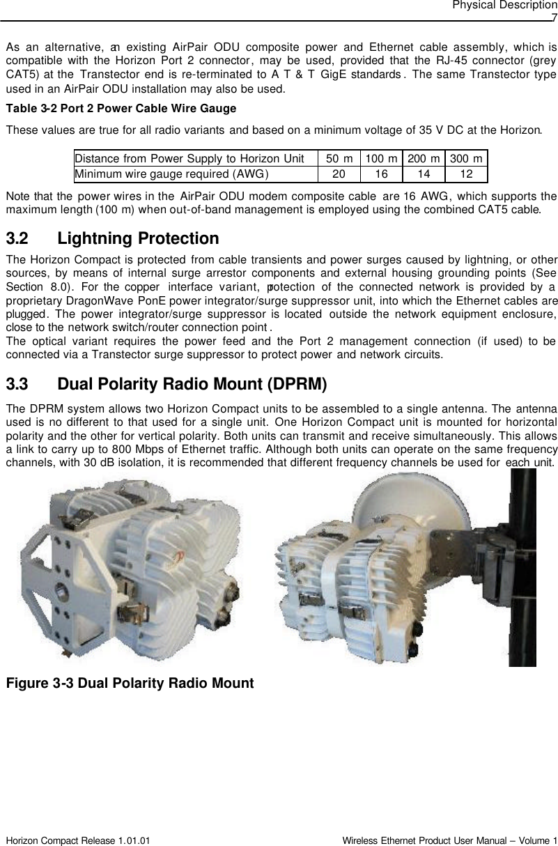


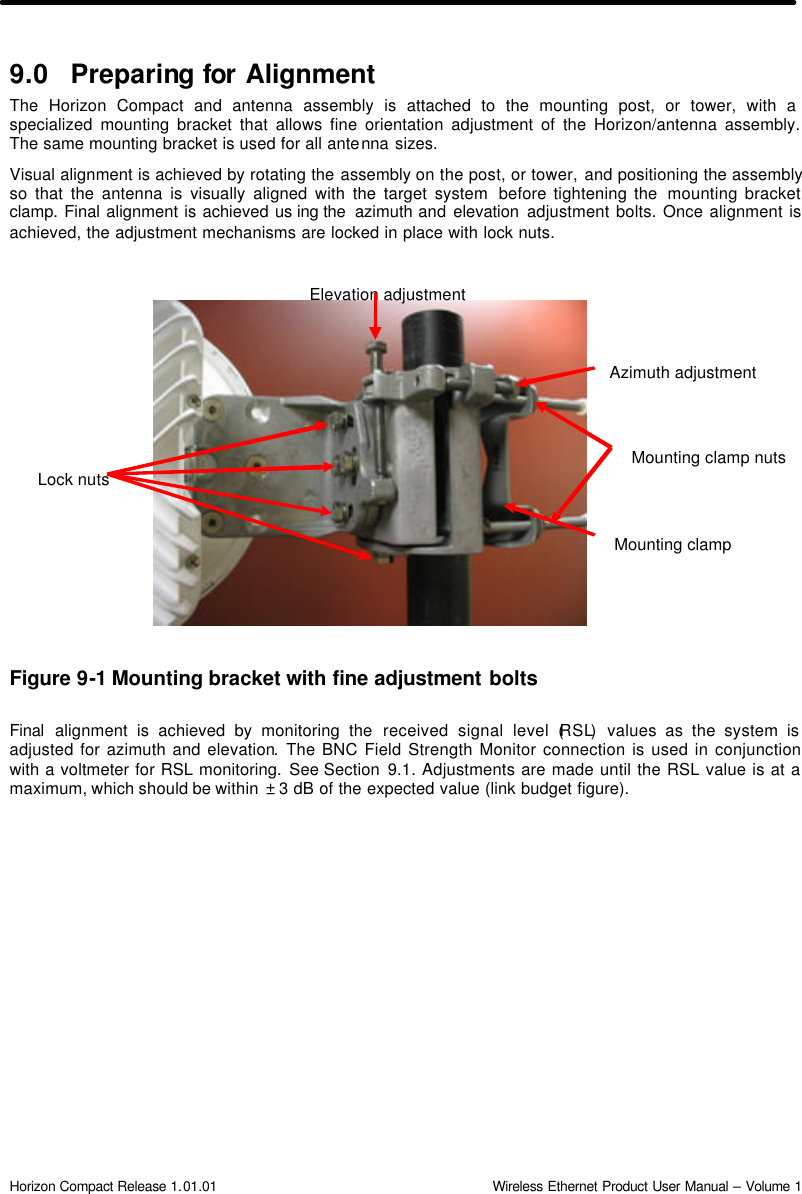
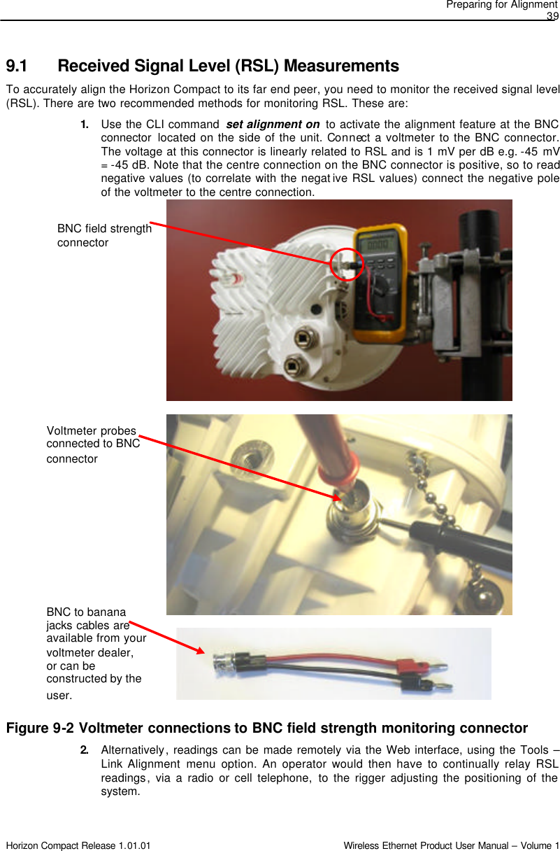
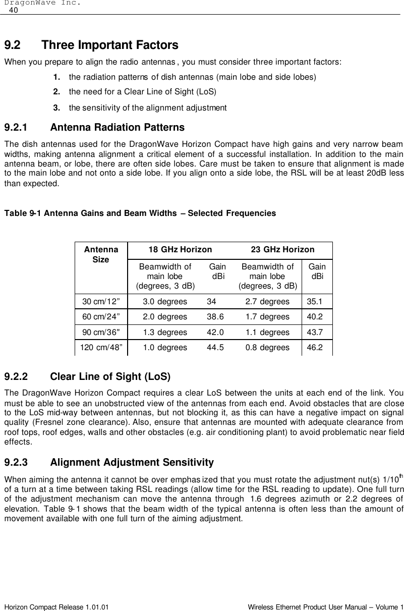
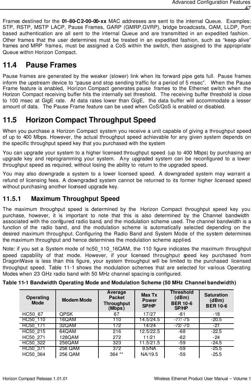
![Advanced Configuration Features 45 Horizon Compact Release 1.01.01 Wireless Ethernet Product User Manual – Volume 1 11.2 Management VLAN Tagging Note: The configuration of Horizon Compact VLAN tagging is only necessary if you wish to restrict Horizon Compact management communications to a specific management VLAN. The Horizon Compact system will pass user VLAN traffic transparently, independent of the Horizon Compact VLAN settings. The VLAN settings are for Horizon Compact management purposes and do not affect user data or traffic. VLAN Standard IEEE 802.1Q is supported for Horizon Compact VLAN tagging and it accommodates up to 4096 VLANs within the “8100” VLAN range. Note that the Horizon Compact system handles Ethernet frame sizes up to 9600 bytes. There are three parameters associated with Horizon Compact VLAN tagging: 1. Enable or disable VLAN tagging (set VLAN tagging [on/off]) 2. Identify the VLAN tag id to be used with Horizon Compact (set VLAN tag [tag id]) 3. Determine whether to allow Horizon Compact to match the VLAN settings in response to incoming frames, or whether to restrict responses to those incoming frames containing the programmed VLAN tag. There are two modes (set network protocol strict [off/on]) which are commonly known as “friendly” and “strict” mode. i. “Friendly” mode. In this mode, Horizon Compact matches the VLAN format of the incoming frame. If an incoming frame contains a VLAN tag, then Horizon Compact responds with a VLAN tag matching the incoming frame. If the incoming frame does not contain a VLAN tag then Horizon Compact does not insert a VLAN tag in the response. Frames generated by Horizon Compact (e.g. SNMP traps) will contain the programmed VLAN tag. ii. “Strict” mode. Horizon Compact will only respond to frames containing the programmed VLAN tag. All other frames will be ignored. Frames generated by Horizon Compact (e.g. SNMP traps) will always contain the programmed VLAN tag. 11.3 802.1P Priority Queuing Implementation in Horizon Compact QoS implementation is best done on the ingress and egress portions of the transport network. As such, QoS should be implemented on the Ethernet switches. Once that implementation is in place, the Horizon Compact can be configured for QoS, should the potential for congestion exist. Enabling CoS/QoS (802.1P) on Horizon Compact ensures that the high priority traffic is delivered at the expense of lower priority traffic. Horizon Compact supports the eight Classes of Service (CoS ) levels (0-7) defined within 802.1P. There are four CoS Queues within Horizon Compact, numbered 1 to 4. Any of the eight CoS levels can be assigned to any of the four Horizon Compact CoS Queues. Horizon can also be configured to use the priority bits found in the DSCP field of IP headers. Any frames not having an IP header can be classified based on the default class of service value (set cos default value [0 though 7]). There are three additional Horizon Compact settings that can be used to customize the data flow to match network requirements: 1. CoS Committed Information Rate (CIR), which determines the guaranteed bandwidth allocated to a particular Queue. 2. CoS Committed Burst Size, which determines the amount of burst data the Queue can manage. 3. Expedite Queuing (see Section 11.3.3), which allows a Queue to be set as a priority Queue whereby it delivers its data at the expense of other non-Expedite Queues.](https://usermanual.wiki/DragonWave/HC-24UL/User-Guide-908839-Page-55.png)
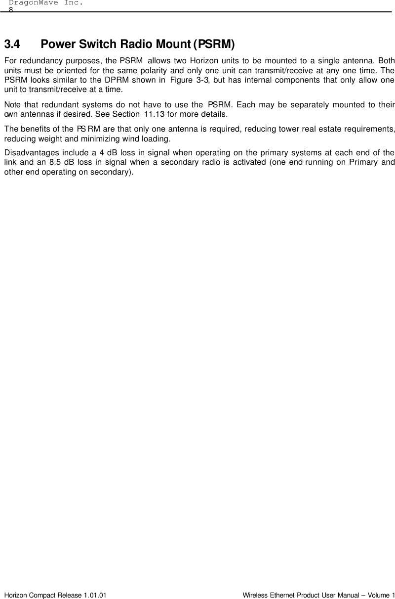
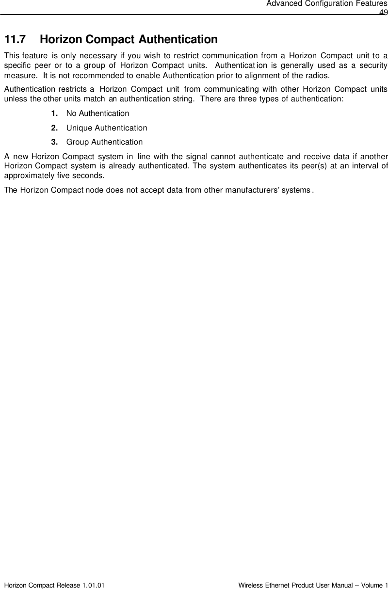
![DragonWave Inc. 48 Horizon Compact Release 1.01.01 Wireless Ethernet Product User Manual – Volume 1 Note: The average packet throughput is calculated using 64, 128, 256, 512, 1024, 1280, and 1518bytes Ethernet frames. ** Throughput optimized to fit within required spectral mask limits. 11.6 Adaptive Transmit Power Control (ATPC) Adaptive Transmit Power Control (ATPC) allows a Horizon Compact system to adjust its transmit power to compensate for far end signal loss caused by changes in atmospheric conditions e.g. heavy rain. ATPC maintains the RSL at -50 dB and adjusts the transmit power by up to 20dB as necessary in order to maintain -50 dB during fade conditions. RSL threshold levels that trigger power changes, the maximum power change allowed, and a hysteresis factor are preset at values which optimize the operation of the Horizon Compact system. A fade factor of 5dB/second can be handled. The Horizon Compact system is able to discriminate between RSL levels that are reduced as a result of interference and those as a result of genuine path loss, so that ATPC is not invoked unnecessarily. Some jurisdictions require the use of ATPC so that power levels are kept as low as possible when wireless communication conditions are good. When ATPC is to be used, if it can be shown that the maximum power of the system would be used only on infrequent occasions, some jurisdictions will allow a lower power level to be used in the calculations that determine interference criteria. Th is offers some advantage to the installation. This lower power is termed the “coordinated power”. The DragonWave ATPC feature supports a coordinated power parameter. ATPC is enabled or disabled by issuing the CLI command set atpc [on/off][coordinated power] The current status of ATPC can be determined by using the CLI command get atpc status. Note: If ATPC and Advanced Adaptive Modulation (AAM) are both enabled, when AAM is invoked i.e. modulation scheme switched to a lower level, ATPC is automatically disabled until AAM restores the original modulation scheme.](https://usermanual.wiki/DragonWave/HC-24UL/User-Guide-908839-Page-58.png)
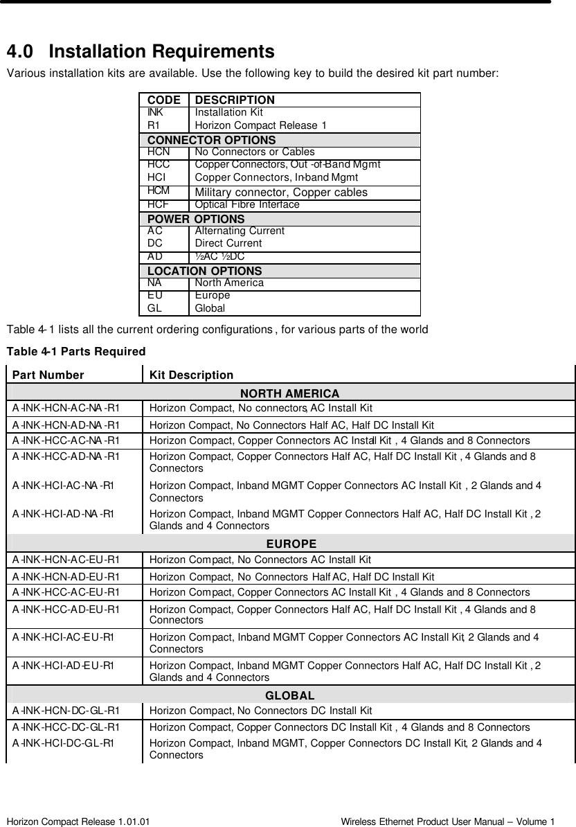
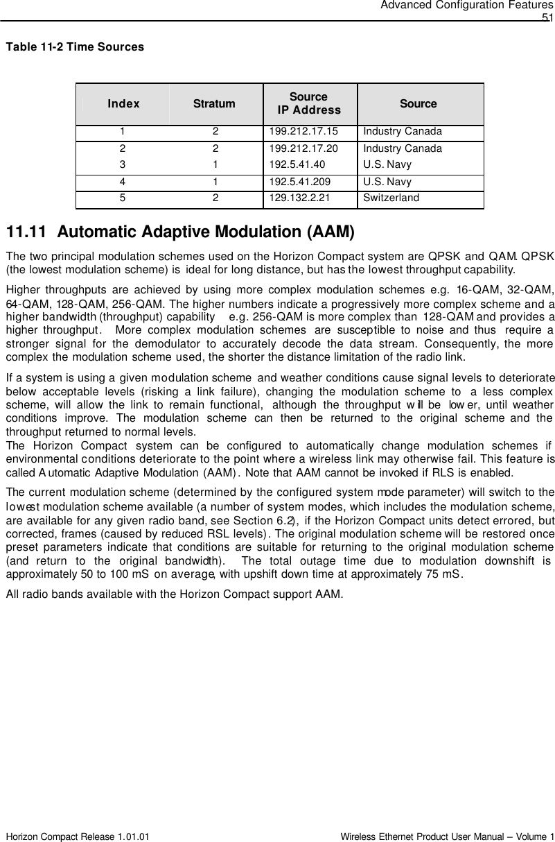
![DragonWave Inc. 50 Horizon Compact Release 1.01.01 Wireless Ethernet Product User Manual – Volume 1 11.8 Threshold Alarms Horizon Compact provides Threshold Alarms to assist in managing the performance of the system. Threshold alarms are available for the following parameters: 1. RSL (Receive Signal Level) 2. Bandwidth Utilization 3. Dropped Frames 4. Signal To Noise (SNR) * With the exception of SNR, each Threshold Alarm has two associated parameters: 1. Threshold value 2. A time limit over which the Threshold value must be exceeded before the alarm is reported. The combination of the value and the time limit is user defined. The proper combination of the two parameters will prevent false alarms from occurring. * For the SNR parameter, only the threshold level can be set, the time limit, or hysteresis , being a preset value. 11.9 Rapid Link Shutdown It is often desirable to signal or detect network link issues in the quickest manner possible. This is especially true when running Layer 2 redundancy protocols, such as Spanning Tree and Metro Ring protocols. Signalling to the network is done by shutting down the Ethernet data port(s) connecting the Horizon Compact to the network. The Rapid Link Shutdown (RLS) feature provides this functionality. Some situations that would result in Rapid Link Shutdown include: • Link outage. Should a power failure or a complete loss of link occur then Ethernet ports at both ends of the link can be shut down • Far-end Ethernet connection problems. If the remote unit data Ethernet port is disconnected or disabled, the near-end unit will also shutdown it’s Ethernet port • Link quality problems. If the link quality (error rate) reaches user programmable thresholds the Horizon Compact Ethernet ports can be shut down • Horizon Compact configuration or hardware failure. If hard faults, such as a hardware failure, interrupt the link, both Horizon Compact Ethernet ports can be shut down. 11.10 Configuring the Time Source (SNTP) Date and time information can be entered into the system using CLI command set date time [dd/dd/yyyy hh:mm:ss:ms] press Enter. The date and time settings in Horizon Compact are not maintained if a power outage is experienced. To ensure that set system date and time are always accurate, the system can poll known time sources and update time information on an ongoing basis. Up to five time sources can be configured, which can provide accurate time and date information to the system. Simple Network Time Protocol (sntp) is used. Either an Internet time source or an NTP server on your network may be used. Five time sources are configured by default (see Table 11-2). Each time source is indexed 1 to 5. Indices 1 and 2 are from Industry Canada servers, 3 and 4 are from U.S. Navy servers and 5 is from a Swiss server. Any other time sources can be configured. The timing information is polled every 60 minutes.](https://usermanual.wiki/DragonWave/HC-24UL/User-Guide-908839-Page-60.png)
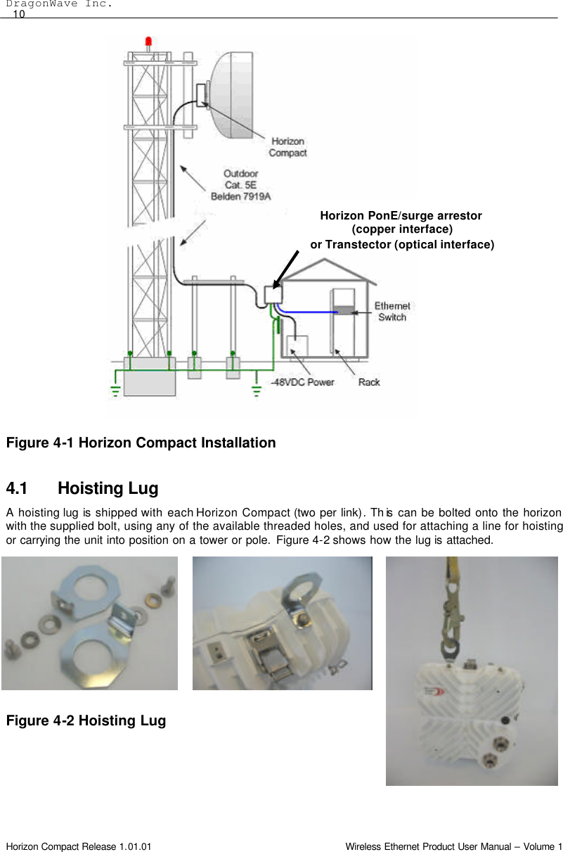
![Horizon Management 59 Horizon Compact Release 1.01.01 Wireless Ethernet Product User Manual – Volume 1 12.1.2 Management through Port 2 (out-of-band) Port 2 is available for out-of-band management purposes only. It does not carry customer data traffic. It has been designed to be used in conjunction with a management overlay network that is separate from the customer data network. The management overlay network is typically extended back to the Network Operations Center. To select out -of -band management use the CLI command set network management interface port2 and press Enter. This allows management of the near end unit only. To gain access to the far end unit use the CLI command set network management interface port2 extended and press Enter. Note: With this “extended” command, an Ethernet connection must NOT be present on Port 2 of the far end system otherwise a network loop will be created. Port 2 supports management of the Horizon Compact system through Telnet sessions , SNMP and the Web interface. When the management interface has been set to "port2", all management traffic must arrive on Port 2, otherwise it is ignored by the system. Customer data traffic continues to be carried over Port 1. 12.2 Telnet Access Once correctly configured, the Horizon Compact is accessible through a Telnet session using Super User, NOC and Admin level user accounts. Refer to Appendix A for details of CLI commands. The Horizon Compact system can be completely configured, tested and managed through a Telnet session. The Telnet function is enabled by default but can be disabled within the Horizon Compact system. Use the CLI command set telnet [on/off] to enable or disable Telnet access. 12.3 Secure Shell Access Security Telnet sessions over a network, such as the Internet , are not secure. User names and passwords, as well as commands and system responses, are transmitted in clear text during a Telnet session. A secure shell (SSH) protocol can be enabled in the Horizon Compact system to ensure that access to the units is restricted to authorized clients. Horizon Compact uses the Secure Shell SSH2 server programme to create the secure environment for Telnet sessions. SSH2 is a recognised industry standard, encrypting, security programme. When enabled, SSH encrypts the entire Telnet session, including all usernames, passwords, commands and responses from the system. SSH also verifies that you are talking to the desired server by means of an authentication process using a “fingerprint”. The “fingerprint” is a unique identifier found only on the desired server. Enable/disable SSH by issuing the CLI command set ssh server [on/off] then press Enter. The server “fingerprint” can be returned by issuing the CLI command get ssh server fingerprint then press Enter. A Secure Shell client programme needs to be installed on any computer which is to be used to manage a Horizon Compact system with SSH enabled. A free SSH client programme (PuTTY) is available on the Web. Note that both SSH and Telnet can be enabled at the same time. To ensure security, once SSH has been enabled, disable Telnet. 12.4 Supported SNMP Versions DragonWave Horizon Compact systems support three versions of SNMP. • Version 1 (SNMP v1) is the initial implementation of SNMP. • Version 2 (SNMPv2c) is the second release of SNMP, which has additions and enhancements to data types, counter size and protocol operations. • Version 3 (SNMPv3) is the most recent version of SNMP. The functionality of SNMPv1 and SNMPv2c remain intact, but SNMPv3 has significant enhancements to administration and security.](https://usermanual.wiki/DragonWave/HC-24UL/User-Guide-908839-Page-69.png)
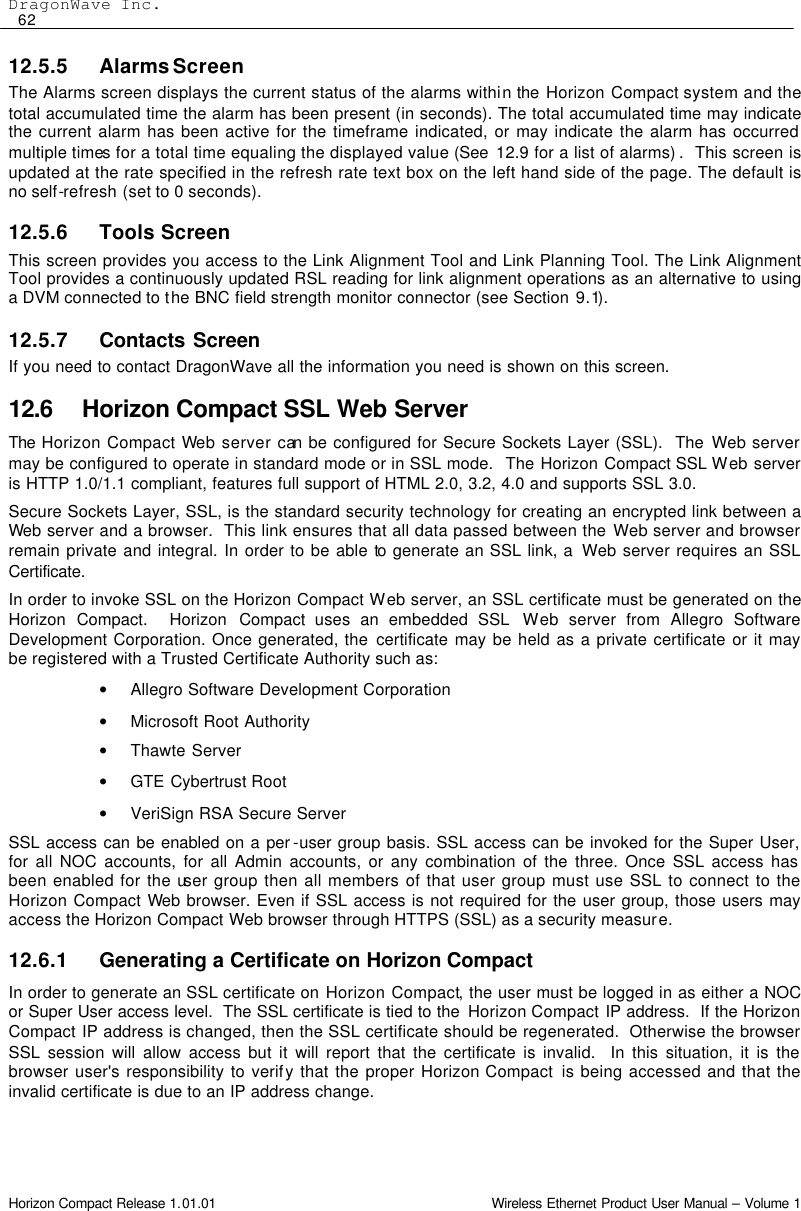
![Horizon Management 61 Horizon Compact Release 1.01.01 Wireless Ethernet Product User Manual – Volume 1 Sub -menu Options The main screen has four Sub-menu options : • More Information - opens a window and displays a summary of the system configuration. • System Name - link to the System Configuration page. If this field has been previously configured then the value is displayed • System Location - link to the System Configuration page. If this field has been previously configured then the value is displayed • Manage your Peer Horizon system : [IP address] - links to the login screen of the peer node (provided the peer node has had its IP address configured). This provides the user with a web browser interface to each end of the Horizon Compact link. • Navigation Bar - Click on the navigation bar across the top of the page to navigate to different screens. Each menu option displays a single screen. 12.5.2 Performance Screen The performance screen displays the traffic statistics for the Horizon Compact link. There are three groups of statistics reported: 1. Ethernet traffic statistics from the point of view of the modem NIC in and out from the local Ethernet cable (payload) and 802.1P priority Queues 2. Modem-to-modem communication for Port 2 3. Modem-to-modem communication for Port 1 This screen is updated at the rate specified in the refresh rate text box in the System Status Pane. 12.5.3 Configuration Screen The main configuration screen provides hypertext links to each of the configuration sections within the Horizon Compact system. To navigate to the individual sections, click on the hypertext link. The Configuration screen allows the user to access the following sections : System Configuration Automatic Transmit Power Control (ATPC) Configuration IP Configuration Automatic Adaptive Modulation (AAM) Configuration Frequency and Port configuration SNTP Configuration SNMP Trap Hosts Configuration Logs Configuration SNMP Managers Configuration RADIUS Client Configuration SNMP V3 Managers Configuration Ethernet Quality of Service SNMP Traps Configuration 12.5.4 Diagnostics Screen The diagnostics screen has a link that directs you to the DragonWave support Web page, where you can download diagnostics programmes. Deleted: ¶¶¶¶¶¶¶¶¶¶¶¶¶¶¶¶¶Deleted: queue](https://usermanual.wiki/DragonWave/HC-24UL/User-Guide-908839-Page-71.png)
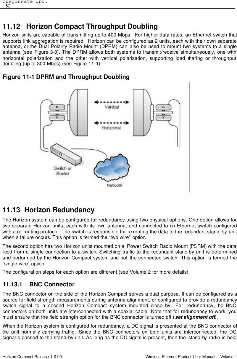
![Horizon Management 63 Horizon Compact Release 1.01.01 Wireless Ethernet Product User Manual – Volume 1 12.7 Event and Performance Logs The Horizon Compact system supports two logs, the Events Log and the Performance Log. Each can be used to trace the behaviour of the system over time. The Events Log is invoked or disabled by issuing the CLI command set logging [on/off]. This log records alarm and reset events. Approximately 17,500 events can be captured by the Events log. Once the log is full the oldest entries are overwritten. Use the CLI command get log entries and press Enter, to display log entries. Use Ctrl C to abort the listing. Issuing the CLI command set performance logging [on/off] enables or disables the Performance Log. This log collects system performance information at time intervals that are configured using the CLI command set performance log interval [hh:mm:ss]. Use the CLI command get performance log and press Enter, to display a list of Performance Log entries. Use Ctrl C to abort the listing. Between 6000 and 8000 entries can be logged before the Performance Log memory is full. Once the memory is full, new entries will overwrite the oldest entries. The following table assumes that an average of 7000 entries will occur before memory overflow. If the memory accepts more entries, then the log duration before overflow will be extended. 12.8 Radio Loopback Horizon provides a radio loopback facility for analysis of transmit or receive path issues. Invoking a radio loopback is service affecting and will stop all data transfer. There are two options: • Straight radio loopback - Ethernet traffic is not looped back to the network, Ethernet traffic is discarded and the RF portion of the Horizon unit is placed in loopback (see Figure 12-2). • Radio loopback plus network loopback – Ethernet traffic and the radio are placed in loopback During the loopback, if the modem transmitter loss of sync alarm is not active, then both the transmitter and receiver of the Horizon unit under test are functioning correctly. A user configurable time limit can be applied to the loopback feature (default is 30 seconds). Once the time limit has expired the loopback will be automatically removed. Note that the far end transmitter should be muted when analysing the near end system using the radio loopback feature. The radio loopback is invoked or disabled by issuing the CLI command set radio loopback [on/off] [time][network]. Figure 12-2 Radio Loopback Network loopback Straight radio loopback Logging Interval Log Duration 15 secs (minimum) ~ 29 hours 1 minute ~ 116 hours (~ 4.8 days) 15 minutes (default) ~ 73 days (~ 2.4 months) 1 hour ~ 292 days (~ 9.7 months) 24 hours (maximum) 7000 days (~ 19.2 years)](https://usermanual.wiki/DragonWave/HC-24UL/User-Guide-908839-Page-73.png)


![Horizon Compact Release 1.01.01 Wireless Ethernet Product User Manual – Volume 1 Appendix A – List of CLI Commands Command Syntax Summary (alpha order) ? (help) copy [ftp:filename] create ssl certificate delete mib [newest|both] delete radius server [index] diagnose aam downgrade system licensed speed [speed] erase log erase performance log exit get aam status get alarms get alarms counter get alignment get air interface authentication type get antenna diameter get atpc status get authentication failure action get authenticated peer get authentication status get backup ipconfig get bandwidth utilization threshold get bandwidth utilization status get config commands get cos default value get cos expedite queue get cos qinq itag get cos qinq otag get cos queue cir get cos queue mapping get cos queue cbs get cos type get date time get default ipconfig get default gateway get dropped frames threshold get enet address get enet config get enet speed get enet status get frequency bank get frequency file crc get frequency file status get group authentication key get health get http secure access [Admin|Noc|Super] get hw inventory get ip address get install type get leds get licensed speed count get logging get log entries get maximum frame size get modem modulation get modem statistics get network management interface get network protocol strict get omni file crc get optical transmitter state get pause state get performance log get performance logging get performance log interval get programmed frequency get qos get radio band get radio loopback get radio statistics get radio status get radio transmitter state get radius servers get radius server retransmit get radius server timeout get radius server deadtime get radius super user authentication get redundancy link monitor parameters get redundancy mode get redundancy override get redundancy partner information get redundancy secondary enet state get redundancy status get rls get rls link enable get rls link monitor parameters get rls link control get rls make rsl get rls signal fault parameters get rls status get rsl threshold get sessions get snmp access mode get snmp managers get snmp set request get snmp traps get snmp trap hosts get snmpv3 managers get snmpv3 trap hosts get snr threshold get sntp get sntp offset get ssh server get ssh server fingerprint get ssl certificate status get subnet mask get super user get sw inventory get sw version get system licensed speed downgrade information get system mode get system speed get system summary](https://usermanual.wiki/DragonWave/HC-24UL/User-Guide-908839-Page-80.png)
![Appendix A 71 Horizon Compact Release 1.01.01 Wireless Ethernet Product User Manual – Volume 1 get system redundancy get telnet access get traffic statistics get transmit power get unique peer authentication key get user accounts get user session get vlan tag get vlan tagging get web server kill ssh sessions list [ftp:file/directory/] lo ping [-w timeout][-n count][-t][ip address] reset [system / modem] save config [ftp:filename] save log [ftp:filename] save mib save performance log [ftp:filename] save users [ftp:filename] set aam [on/off] set admin user set air interface authentication type [type] set authentication failure [action] set alarms counter [0] set alignment [on/off] set antenna diameter [index of diameter] set atpc [on|off][coordinated power] set bandwidth utilization threshold [threshold][time] set cos default value [0-7] set cos expedite queue [on|off] set cos qinq itag [protocol id] set cos qinq otag [protocol id] set cos queue cir [0-100,0-100,0-100,1-100] set cos queue mapping [mapping] set cos queue cbs set cos type [cos_vlan][cos_qinq_itag][cos_qinq_otag] set current channel index set date time [dd/mm/yyyy hh:mm:ss:ms] set default gateway [ip address] set dropped frames threshold [threshold][time] set enet config [port1|port2] set enet speed [port1|port2] speed[10|100|1000|auto] AutoNeg[auto] set frequency bank set group authentication key [key] set http secure access [Admin|Noc|Super] [on|off] set ip address [address] set logging [on|off] set maximum frame size [1600-9600] set network management interface [port1|port2|port2 extended ] set network protocol strict [on|off] set noc user set optical transmitter state [on|off] set pause state [on|off] set performance logging [on|off] set performance log interval [hr:min:sec] set programmed frequency [index] set qos [on|off] set radio transmitt er state [enable|disable] set radio band [band] set radio loopback [on|off] set radio rxgain set radio txgain set radius server key [index] [key] set radius server host [index] [ip address] set radius super user authentication strict [on|off] set redundancy link monitor parameters set redundancy mode set redundancy override [primary|secondary| manual|auto] set redundancy standby enet state [on/off/pulse] set redundancy state switch [on] set rls [on|off] set rls link enable [on|off] set rls link monitor parameters [dn2up frame error] [up2dn frame error] [dn2up samples] [up2dn samples] [sample time] set rls link control [on|off] set rls make rsl [rsl value][time] set rls signal fault parameters [time][% error] set rsl threshol d [threshold][time] set snmp access mode [v1|v2c|off] set snmp manager [mgr index] [ip address] [enable|disable] [community string] set snmp set request [on|off] set snmp trap [trap#] [enable|disable] set snmp trap host [host#] [ip address] [enable|disable] [community string] set snr threshold [threshold] set snmpv3 trap host enable [index] set snmpv3 trap host disable [index] set snmpv3 trap host ip [index] [ip address] set snmpv3 trap host user [index] [none|des] set snmpv3 trap host authentication [indes] [none|md5|sha] [passwd] set snmpv3 trap host privacy [index] [none|des] set sntp [on|off] set sntp default set sntp offset [hrs] set sntp server [index] [ip address] set ssh server set super user [username] [password] set system current speed [speed] set system mode [mode] set system redundancy [on|off] set telnet [on|off] set traffic statistics [0] set transmit power [power in dB] set unique peer authentication key [key] set subnet mask [mask] set vlan tag [vlan ID (0 -4095)] [vlan priority (0-7)] set vlan tagging [on|off] set web server [on|off] upgrade system licensed speed [speed] [key]](https://usermanual.wiki/DragonWave/HC-24UL/User-Guide-908839-Page-81.png)