DragonWave LT5GT Microwave Outdoor Unit User Manual LITE R1 0 Installation Guide Revision 2

DragonWave Inc. Microwave Outdoor Unit LITE R1 0 Installation Guide Revision 2

Contents

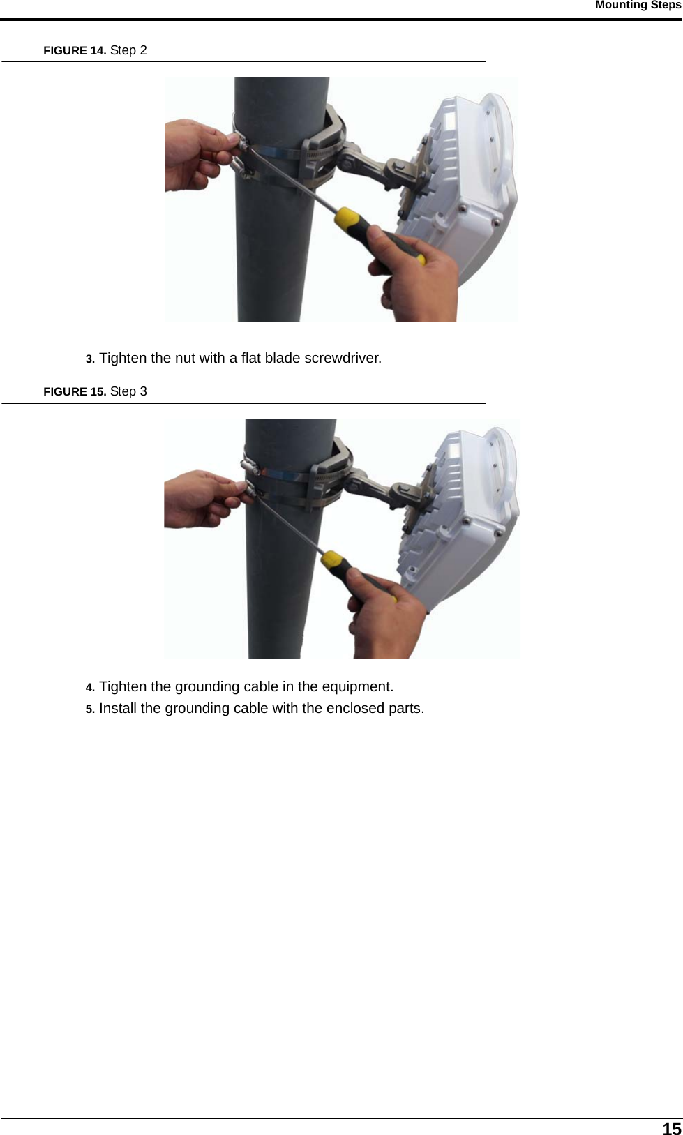
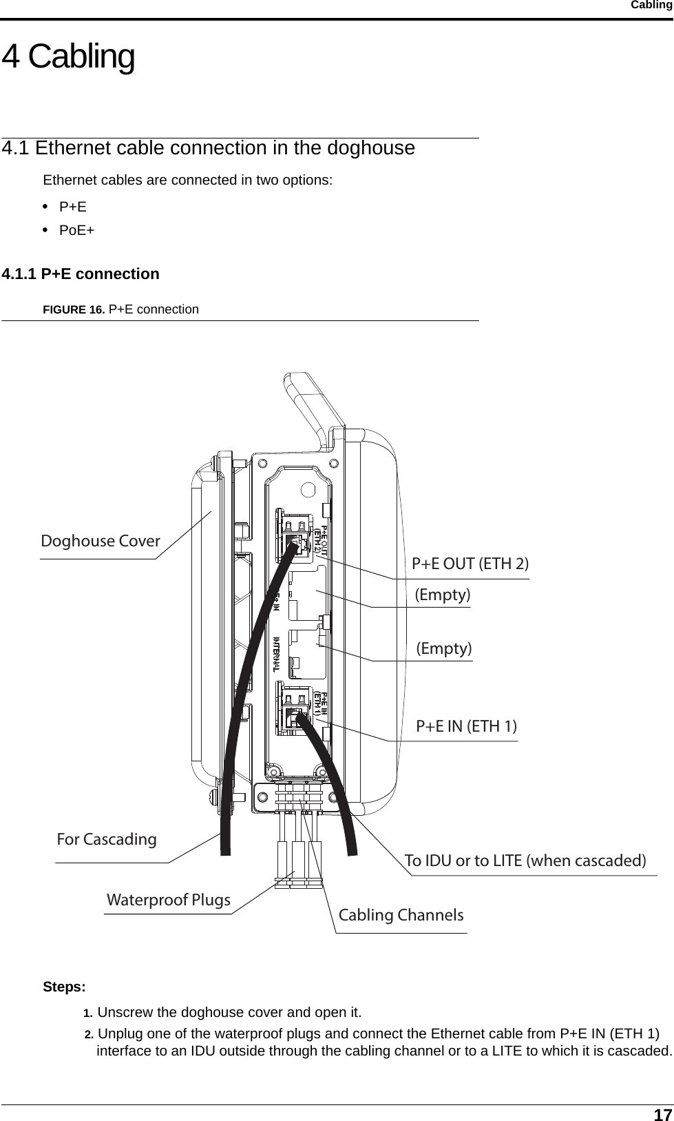
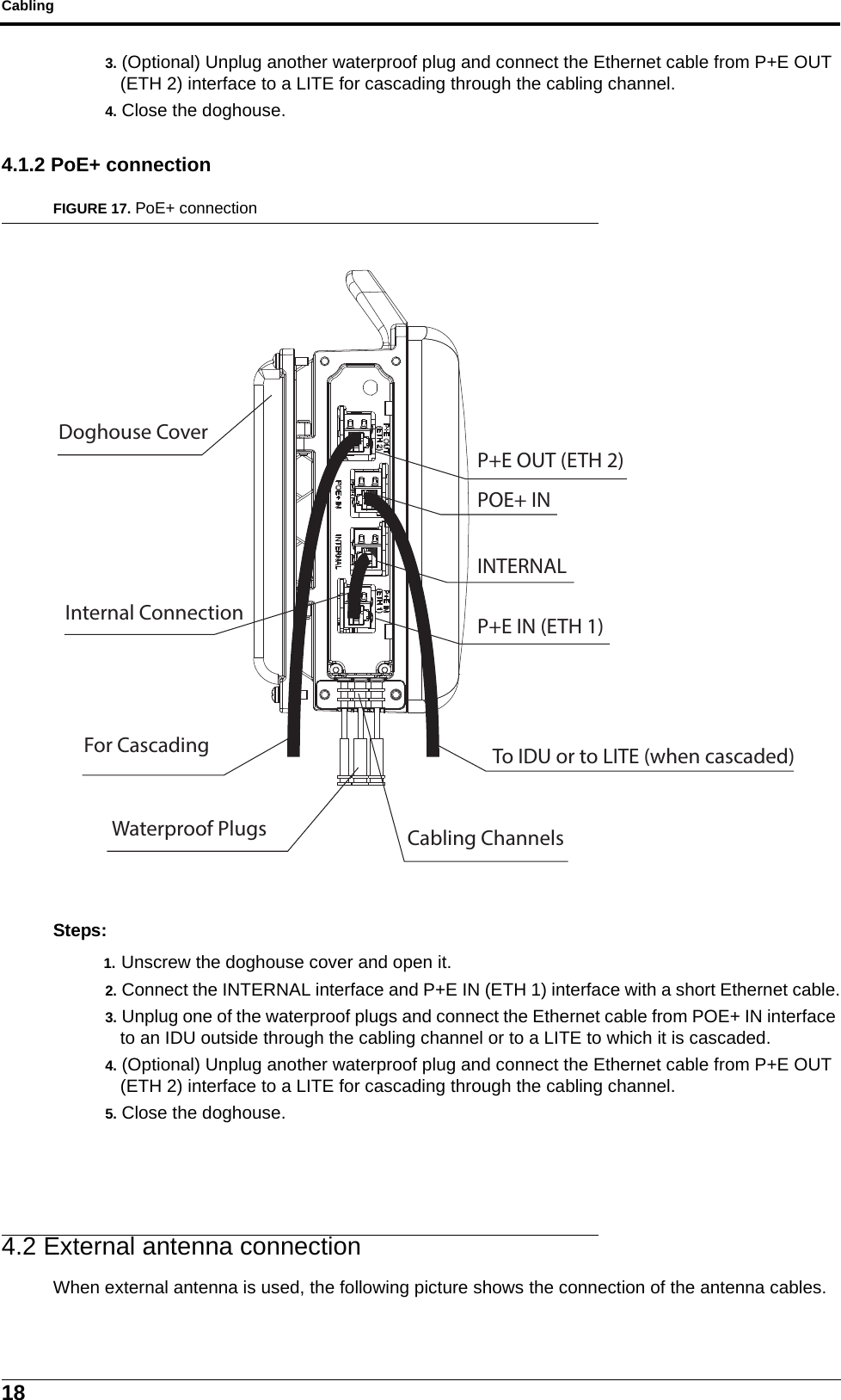
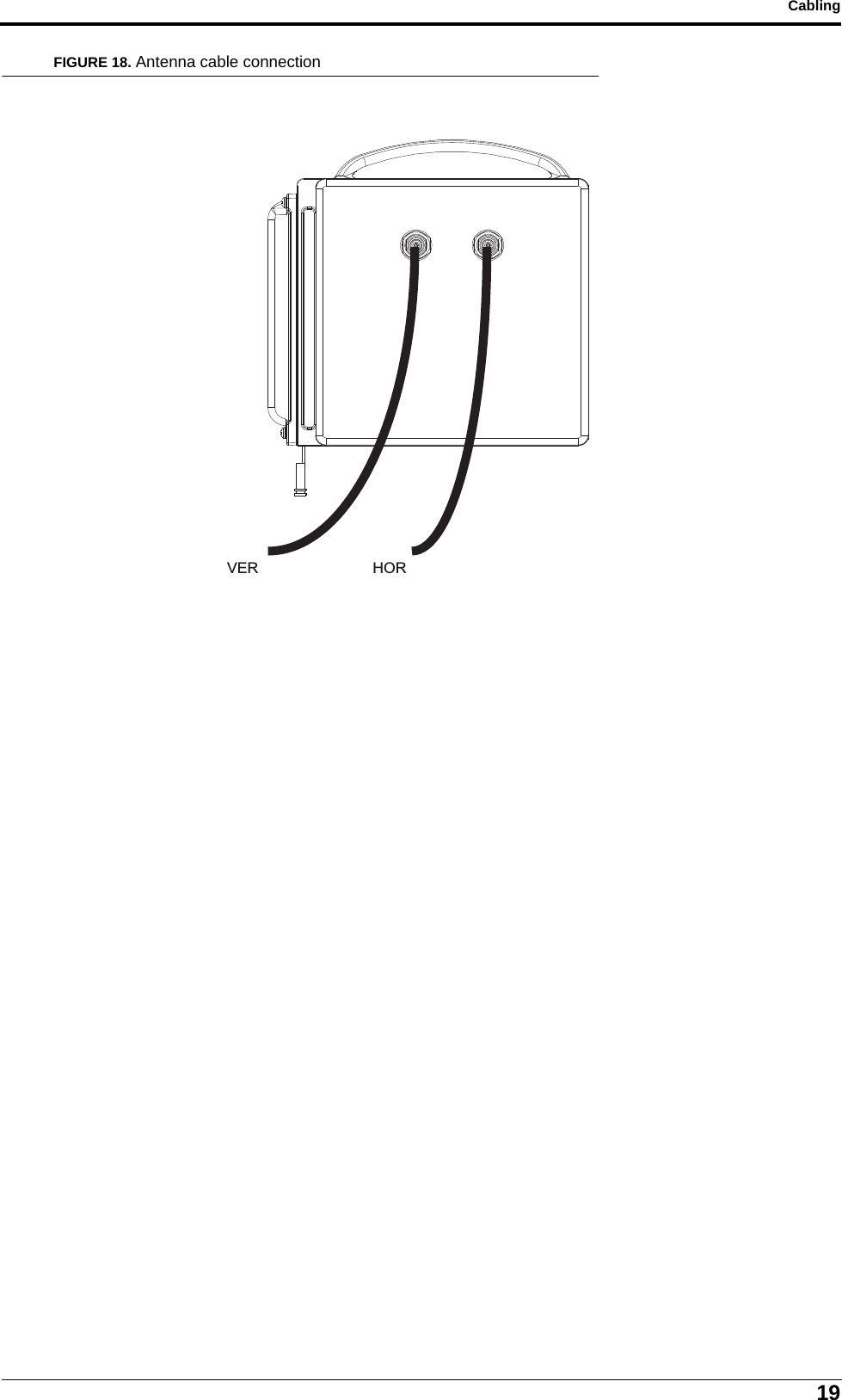
Harmony Lite 5GHz_Installation Guide

LITE, R1.0Installation GuideRevision 2, updated in May, 2014
NoticeThis document contains DragonWave proprietary information. Use, disclosure,copying or distribution of any part of the information contained herein, beyond thatfor which it was originally furnished, requires the written permission ofDragonWave Inc.The information in this document is subject to change without notice and relatesonly to the product defined in the introduction of this document. DragonWaveintends that information contained herein is, to the best of its knowledge, correctand accurate. However, any/all liabilities associated with the use or accuracy ofthe information contained herein must be defined in a separate agreementbetween DragonWave and the customer/user.Copyright © DragonWave Inc. 2014. All rights reserved.
Table of Contents1 Preface  ....................................................................................................51.1 History of changes  ........................................................................................................... 51.2 Scope of the document  .................................................................................................... 51.3 Intended audience ............................................................................................................ 51.4 Document structure .......................................................................................................... 52 Before installation ..................................................................................72.1 Precautions ...................................................................................................................... 72.2 Needed parts .................................................................................................................... 83 Mounting Steps  ....................................................................................113.1 Mounting on the wall  ...................................................................................................... 113.2 Mounting on the pole (1’ ~ 1.75’ diameter)  .................................................................... 133.3 Mounting on the pole (1.75’ ~ 3’ diameter)  .................................................................... 133.4 Mounting on the pole (3’ ~ 4.55’)  ................................................................................... 144 Cabling  ..................................................................................................174.1 Ethernet cable connection in the doghouse ................................................................... 174.1.1 P+E connection ................................................................................................................... 174.1.2 PoE+ connection ................................................................................................................. 184.2 External antenna connection .......................................................................................... 18
5Preface1 Preface1.1 History of changesThe history of changes is shown in the following table:1.2 Scope of the documentThis document provides the guidance to install and commission the LITE system.INFOThis document only concerns LITE system release 1.0 (LITE R1.0 in short) without specificstatements in the context.1.3 Intended audienceThis document is prepared for the use of technicians who are responsible for the system installationand commissioning.WARNING!PERSONS HANDLING THIS EQUIPMENT MAY BE EXPOSED TO HAZARDS WHICHCOULD RESULT IN PHYSICAL INJURY! IT IS THEREFORE MANDATORY TO CARE-FULLY READ AND UNDERSTAND THIS DOCUMENT.1.4 Document structureThe document is comprised of the following chapters.TABLE 1. History of changesRevision Updates Update date1 1st revision August, 20132 In Chapter 2, some warnings are added to meed the requirements. May, 2014TABLE 2. Document structureChapter Title SubjectChapter 1 Preface Provides an introduction on who and how to use this docu-ment.Chapter 2 Before installation Provides some information about the preparations and pre-cautions before the installation.Chapter 3 Mounting steps Provides the mounting steps.Chapter 4 Cabling Provides the cabling guidance.
Preface6
7Before installation2 Before installation2.1 PrecautionsThe radiation emitted by the antenna is low-power radiation and does not exceed the safety regula-tions. If the radio is operated without antenna, the safety limit is exceeded near the waveguide open-ings.WARNING!THE INSTALLATION MUST ONLY BE PERFORMED BY A QUALIFIED TECHNICIAN.WARNING!RISK OF PERSONAL INJURY. THIS PRODUCT MAY NEED TO BE INSTALLED ON AHIGH-RISE STRUCTURE SUCH AS A TOWER OR MAST. WHEN INSTALLING THEPRODUCT, WEAR A SAFETY HARNESS AND OTHER RELEVANT PROTECTIVE GEAR.IN ADDITION, FOLLOW ALL OCCUPATIONAL HEALTH AND SAFETY REGULATIONSAPPLICABLE TO THE INSTALLATION.WARNING!HAZARDOUS ENERGY EXISTS WITHIN THE DEVICE. ALWAYS BE CAREFUL TO AVOIDELECTRIC SHOCK.WARNING!THE EQUIPMENT SHOULD BE LOCATED IN RESTRICTED ACCESS LOCATIONS.WARNING!WHEN INSTALLING THE UNIT, ALWAYS MAKE THE GROUND CONNECTION FIRST ANDDISCONNECT IT LAST.WARNING!THE DEVICE MUST BE CONNECTED PERMANENTLY TO THE PROTECTION GROUNDBEFORE AN OPERATION. THE CROSS-SECTIONAL AREA OF THE PROTECTIVEGROUND CONDUCTOR MUST BE AST LEAST 18AWG.WARNING!THE DEVICE MUST BE FIXED SECURELY ON RELIABLE OBJECTS.WARNING!REINFORCED INSULATION OR DOUBLE INSULATION MUST BE PROVIDED TO ISO-LATE DC SOURCE FROM AC MAIN SUPPLY WHICH COMPLIES WITH REQUIREMENTSIN IEC 60950-1 BASED SAFETY STANDARDS.The following restrictions must be considered before installing the equipment:• The weather conditions must be taken into account when installing the equipment. The maximum and minimum temperatures at the installation location must remain within the acceptable range. For cable installation temperatures, refer to the cable manufacturer’s specifications.• The mounting pole structure must be stable enough to keep the antenna within its 3dB beam-width in all foreseeable wind conditions.• Do not install the equipment at a location where an unauthorized person can have access to the antenna radiation region or to the equipment itself.
Before installation8• When the equipment is installed in regions where the temperature falls below zero degree Celsius during the winter, ice can accumulate on the installation tower structure. Take precautions to avoid the breakage of antennas due to falling ice. Suitable protection can be achieved, by install-ing a metal grating above the antenna.2.2 Needed partsBefore starting the installation, verify that you have the correct equipment and that the equipmenthas not been damaged during transportation.The following parts are needed in the normal installation of the equipment:• 1 X LITE equipment;FIGURE 1. LITE appearance (with internal antenna)For more information on the physical design of the equipment, refer to Volume 1, Chapter 4 Mechanical structure and interfaces.• 2 x pre-assembled outdoor Ethernet cables (length options: 1 m, 2 m, 5 m, 10 m, 30 m, 50 m, 70 m, 90 m);• 1 x grounding cable;223.1 mm217.87 mm190.14 mm88.30 mmWith 190x190 mm Internal Antenna8.4 mm8.4 mm86 mm66 mmWith External Antenna
9Before installation• (Only needed when PoE+ function is required) 1 x Ethernet cable for LITE internal use (length: 0.12 m);• (Only needed when external antenna is used) 2 x pre-assembled antenna cable for sub-6 GHz with connectors (length options: 1 m, 2 m, 3 m, 4 m, 5 m); and• 1 set of mounting kit.FIGURE 2. Mounting kit itemsINFOHow to attach the mounting kit to the equipment? The following steps will be used in the equip-ment mounting steps.Steps:1. Attach item 1 to the back of the equipment using item 2, 3 and 4 as shown. Verify that the orientation of the hole in item 1 is aligned with the elevation axis. Using tightening torque of 5.7 N/m.Arm bracketQty: 1SHEET 1 OF 4Spring washer M5Qty: 4Item: 3Bolt  M5x16Qty: 4MT-120018/A onlyBolt  M8x40Qty: 4Wall/Poll bracketQty: 1Antenna/enclosure base bracketQty: 1Item: 1Washer spring M8Qty: 4Flat washer M5Qty: 4Item:2Clamping bracketQty: 1Washer flat M8Qty: 4Bolt  M8x70Qty: 2Nut M5Qty: 4Item: 4Item: 5Item: 10Item: 8Item: 6Item: 12Item: 13Item: 11Item: 9Item: 7Nut M8Qty: 2
Before installation10FIGURE 3. Step 12. Connect base bracket as shown. Connect item 5 to item 1 (mate the knurled surfaces) using item 6, 7, 8 and 9. Note that the bolt head shall be positioned in the socket of item 1. Using tightening torque of 24 N/m to the azimuth and elevation hardware.FIGURE 4. Step 2ELEVATIONAXIS421x43x4x41510987667 8 9ElevationaxisAzimuth axis
11Mounting Steps3 Mounting StepsThe equipment can be mounted in the following four options:• Option 1: on the wall;• Option 2: on the pole (1’ ~ 1.75’ diameter);• Option 3: on the pole (1.75’ ~ 3’ diameter); or • Option 4: on the pole (3’ ~ 4.55’ diameter).3.1 Mounting on the wallSteps:1. Install the M6 x 60 expansion bolt in the wall.FIGURE 5. Step 12. Attach the mounting kits to the wall by M6 x 60 expansion bolt.FIGURE 6. Step 23. Attach the mounting kits to the equipment. Refer to Chapter 2 Before installation.
Mounting Steps12FIGURE 7. Step 34. Tighten the grounding cable in the equipment.FIGURE 8. Step 45. Install the grounding cable with the enclosed parts.FIGURE 9. Step 5
13Mounting Steps3.2 Mounting on the pole (1’ ~ 1.75’ diameter)Steps:1. Attach the mounting kits to the equipment. Refer to Chapter 2 Before installation.2. Pre-assemble the mounting bracket on the pole.FIGURE 10. Step 23. Tighten the nut with spanner.FIGURE 11. Step 34. Tighten the grounding cable in the equipment.5. Install the grounding cable with the enclosed parts.3.3 Mounting on the pole (1.75’ ~ 3’ diameter)Steps:1. Attach the mounting kits to the equipment. Refer to Chapter 2 Before installation.2. Pre-assemble the mounting bracket on the pole.
Mounting Steps14FIGURE 12. Step 23. Tighten the nut with spanner.FIGURE 13. Step 34. Tighten the grounding cable in the equipment.5. Install the grounding cable with the enclosed parts.3.4 Mounting on the pole (3’ ~ 4.55’)Steps:1. Attach the mounting kits to the equipment. Refer to Chapter 2 Before installation.2. Pre-assemble the mounting bracket on the pole.
15Mounting StepsFIGURE 14. Step 23. Tighten the nut with a flat blade screwdriver.FIGURE 15. Step 34. Tighten the grounding cable in the equipment.5. Install the grounding cable with the enclosed parts.
Mounting Steps16
17Cabling4 Cabling4.1 Ethernet cable connection in the doghouseEthernet cables are connected in two options:• P+E• PoE+4.1.1 P+E connectionFIGURE 16. P+E connectionSteps:1. Unscrew the doghouse cover and open it.2. Unplug one of the waterproof plugs and connect the Ethernet cable from P+E IN (ETH 1) interface to an IDU outside through the cabling channel or to a LITE to which it is cascaded.Doghouse CoverP+E OUT (ETH 2)(Empty)(Empty)P+E IN (ETH 1)For CascadingTo IDU or to LITE (when cascaded)Cabling ChannelsWaterproof Plugs
Cabling183. (Optional) Unplug another waterproof plug and connect the Ethernet cable from P+E OUT (ETH 2) interface to a LITE for cascading through the cabling channel.4. Close the doghouse.4.1.2 PoE+ connectionFIGURE 17. PoE+ connectionSteps:1. Unscrew the doghouse cover and open it.2. Connect the INTERNAL interface and P+E IN (ETH 1) interface with a short Ethernet cable.3. Unplug one of the waterproof plugs and connect the Ethernet cable from POE+ IN interface to an IDU outside through the cabling channel or to a LITE to which it is cascaded.4. (Optional) Unplug another waterproof plug and connect the Ethernet cable from P+E OUT (ETH 2) interface to a LITE for cascading through the cabling channel.5. Close the doghouse.4.2 External antenna connectionWhen external antenna is used, the following picture shows the connection of the antenna cables.Doghouse CoverP+E OUT (ETH 2)POE+ ININTERNALP+E IN (ETH 1)Internal ConnectionFor Cascading To IDU or to LITE (when cascaded)Cabling ChannelsWaterproof Plugs
19CablingFIGURE 18. Antenna cable connectionVER HOR
Cabling20

Navigation menu