DragonWave LT5GT Microwave Outdoor Unit User Manual Harmony Lite 5GHz
DragonWave Inc. Microwave Outdoor Unit Harmony Lite 5GHz
Contents
- 1. Harmony Lite 5GHz_Installation Guide
- 2. Harmony Lite 5GHz_User Manual
Harmony Lite 5GHz_User Manual

Harmony Lite, R1.0
Operation and Maintenance Guide
Revision 2, updated in May, 2014
Document Number: PM-000003-01-EN
draft
Notice
This document contains DragonWave proprietary information. Use, disclosure,
copying or distribution of any part of the information contained herein, beyond that
for which it was originally furnished, requires the written permission of
DragonWave Inc.
The information in this document is subject to change without notice and relates
only to the product defined in the introduction of this document. DragonWave
intends that information contained herein is, to the best of its knowledge, correct
and accurate. However, any/all liabilities associated with the use or accuracy of
the information contained herein must be defined in a separate agreement
between DragonWave and the customer/user.
Copyright © DragonWave Inc. 2014. All rights reserved.
draft
Table of Contents
1 Preface ....................................................................................................9
1.1 History of changes ........................................................................................................... 9
1.2 Scope of the document .................................................................................................... 9
1.3 Intended audience ............................................................................................................ 9
1.4 Document structure .......................................................................................................... 9
2 Commissioning ....................................................................................11
2.1 Before commissioning .................................................................................................... 11
2.2 Commission steps .......................................................................................................... 11
2.2.1 Logging in ............................................................................................................................ 11
2.2.2 Setting the management IP ................................................................................................. 12
2.2.3 Setting the management VLAN ........................................................................................... 13
2.2.4 Setting the radio parameters ............................................................................................... 14
3 System configuration ...........................................................................19
3.1 System home ................................................................................................................. 19
3.2 System inventory ............................................................................................................ 19
3.3 Software inventory ......................................................................................................... 20
3.4 Software management ................................................................................................... 21
3.5 Configuration management ............................................................................................ 21
3.6 P+E output .....................................................................................................................22
draft
3.7 Licensing .........................................................................................................................22
3.8 SNTP ..............................................................................................................................23
3.9 Synchronization ..............................................................................................................23
4 Wireless radio configuration ............................................................... 25
4.1 Wireless radio #1 configuration ......................................................................................25
4.2 Received Signal Strength Indication ...............................................................................25
4.3 Modulation and ACM ......................................................................................................26
4.4 Tx power and Adaptive Transmit Power Control (ATPC) ...............................................27
5 Ethernet configuration ......................................................................... 29
5.1 Ports ...............................................................................................................................29
5.2 Speed .............................................................................................................................29
5.3 VLAN management ........................................................................................................30
5.4 QoS scheduler ................................................................................................................30
5.5 Traffic criteria ..................................................................................................................31
5.6 IP priority .........................................................................................................................31
5.7 VLAN PRI priority ............................................................................................................32
5.8 Port priority .....................................................................................................................32
5.9 Aging time .......................................................................................................................33
5.10 Static Unicast FDB ........................................................................................................33
5.11 All FDB ..........................................................................................................................33
6 Management .........................................................................................35
6.1 IP ....................................................................................................................................35
6.2 Management VLAN ........................................................................................................35
6.3 SNMP .............................................................................................................................36
draft
6.4 Trap ................................................................................................................................ 36
6.5 Event log ........................................................................................................................ 36
6.6 Account log ....................................................................................................................37
7 Alarms ...................................................................................................39
7.1 Active alarms ..................................................................................................................39
7.2 History alarms ................................................................................................................ 39
8 Performance .........................................................................................41
8.1 Ethernet .......................................................................................................................... 41
8.2 Wireless ......................................................................................................................... 41
9 Diagnostics ...........................................................................................43
9.1 Link status ...................................................................................................................... 43
9.2 Link status trace ............................................................................................................. 43
9.3 System running log ........................................................................................................ 43
10 About ...................................................................................................45
draft
draft
List of Tables
TABLE 1. History of changes ..................................................................................................................... 9
TABLE 2. Document structure .................................................................................................................... 9
TABLE 3. Login parameters ..................................................................................................................... 12
TABLE 4. System home ........................................................................................................................... 12
TABLE 5. Management IP ........................................................................................................................ 13
TABLE 6. Management VLAN .................................................................................................................. 14
TABLE 7. Wireless parameters ................................................................................................................ 16
TABLE 8. Configuration summary ............................................................................................................ 17
TABLE 9. P+E output ............................................................................................................................... 22
TABLE 10. SNTP ...................................................................................................................................... 23
TABLE 11. ACM ....................................................................................................................................... 27
TABLE 12. TPC ........................................................................................................................................ 27
TABLE 13. Ethernet ports ......................................................................................................................... 29
TABLE 14. Ethernet port speed configuration.......................................................................................... 29
TABLE 15. VLAN configuration ................................................................................................................ 30
TABLE 16. Aging time .............................................................................................................................. 33
TABLE 17. Management VLAN ................................................................................................................35
draft
draft
9
Preface
1 Preface
1.1 History of changes
The history of changes is shown in the following table:
1.2 Scope of the document
This document provides the technical guide for commissioning and operating the software of Har-
mony Lite system, Lite Link Viewer.
INFO
This document only concerns Harmony Lite system release 1.0 (Lite, R1.0 in short) without
specific statements in the context.
1.3 Intended audience
This document is prepared for the use of radio network planners and technicians who are responsi-
ble for the system operation and maintenance.
WARNING!
PERSONS HANDLING THIS EQUIPMENT MAY BE EXPOSED TO HAZARDS WHICH
COULD RESULT IN PHYSICAL INJURY! IT IS THEREFORE MANDATORY TO CARE-
FULLY READ AND UNDERSTAND THIS DOCUMENT.
1.4 Document structure
The document is comprised of the following chapters.
TABLE 1. History of changes
Revision Updates Date
1 1st revision. January,
2014
2 All across the document, the full name of the product is changed to Harmony
Lite.
May, 2014
TABLE 2. Document structure
Chapter Title Subject
Chapter 1 Preface Provides an introduction on who and how to use this document.
Chapter 2 Commissioning Provides the guidance to do the initial commission.
Chapter 3 System configuration Provides the guidance to make system configurations.
Chapter 4 Wireless configuration Provides the guidance to make wireless configurations.
Chapter 5 Ethernet configuration Provides the guidance to make Ethernet configurations.
Chapter 6 Management Provides the guidance to make management configurations.
draft

Preface
10
Chapter 7 Alarms Provides the information about alarm lists.
Chapter 8 Performance Provides the guidance to make performance configurations.
Chapter 9 Diagnostics Provides the guidance to make diagnostics configurations.
Chapter 10 About Provides the information about the link view.
TABLE 2. Document structure
Chapter Title Subject
draft
11
Commissioning
2 Commissioning
2.1 Before commissioning
Before Lite system become operational, initial configuration steps need to be carried out first. And
the Commissioning wizard is recommended to be executed prior to the hardware installation on site.
The Lite system can be accessed by the Web Browser on a PC, such as Google Chrome (28.0 or
higher), Firefox (26.0 or higher), IE (9.0 or higher). If Firefox or IE is to be used, Adobe Flash Player
plug-in has to be installed first. (To download Adobe Flash Player, go to website http://
get.adobe.com/cn/flashplayer/.)
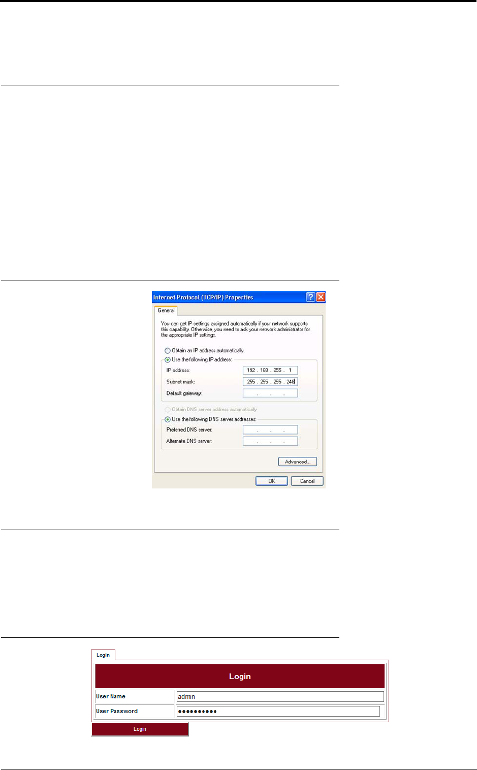
Before logging into the Lite Web interface, the network configuration of the PC must be set as
Figure 1. We suggest setting the PC IP address to 192.168.255.1 and subnet mask
255.255.255.248. This IP address is used to access Lite when the management PC is directly con-
nected to Lite system. By default, the private IP address of Lite is 192.168.255.3 and the subnet
mask 255.255.255.248.
FIGURE 1. PC network configuration
2.2 Commission steps
2.2.1 Logging in
Steps
1. Use the Web Browser to access the private IP address of Lite.
FIGURE 2. Step 1
draft
Commissioning
12
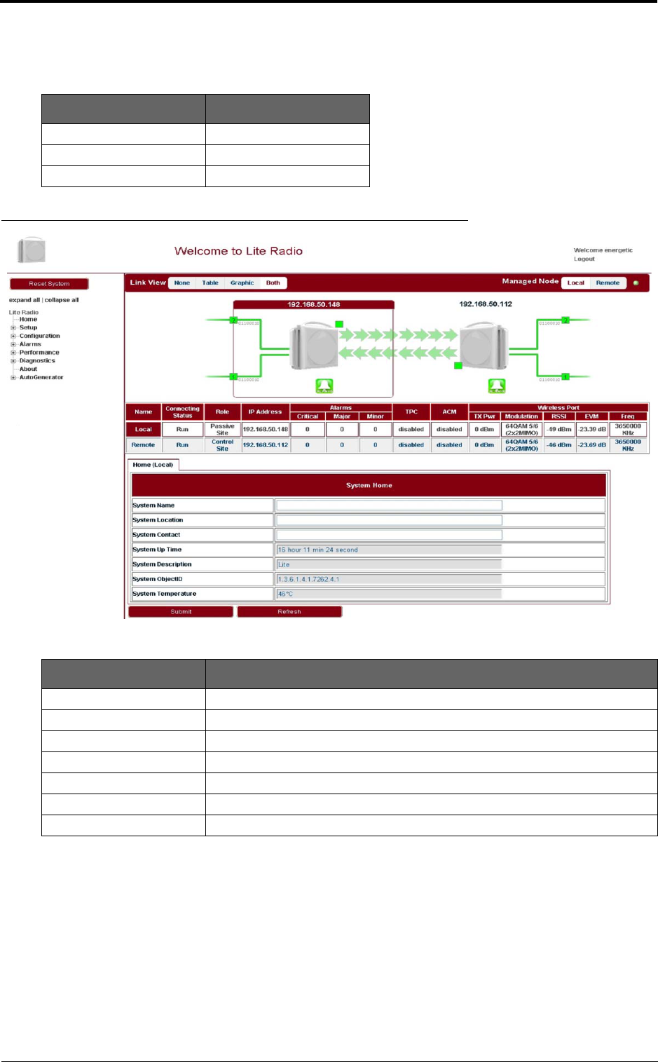
2. Enter User Name and User Password, click Login. The home page of Link Viewer
appears.
FIGURE 3. Link Viewer
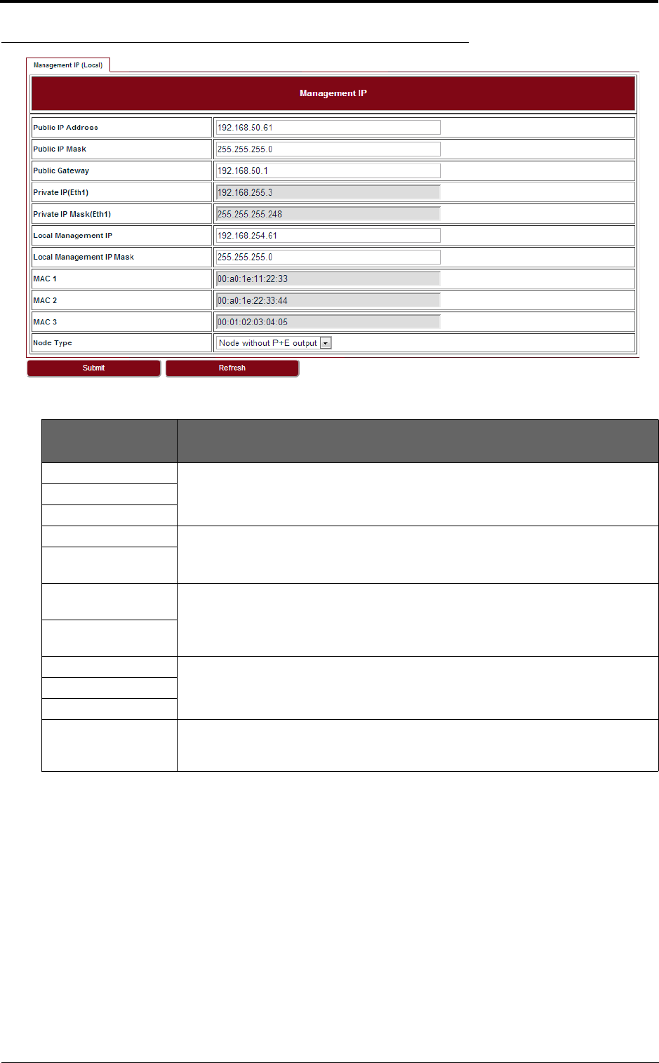
2.2.2 Setting the management IP
Go to Configuration > Management > IP tab (see Figure 4). The public management IP address
and local management IP address are to be set.
INFO
Don’t use IP address from 192.168.254.96 ~ 192.168.254.99. These 4 IP addresses are
reserved for internal use.
TABLE 3. Login parameters
User Name User Password
energetic wireless
readwrite Rwrite
readonly readonly
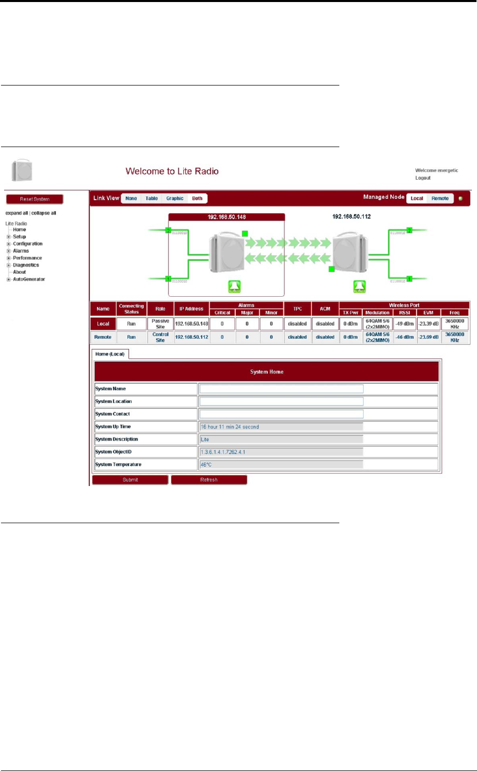
TABLE 4. System home
Parameter Description
System Name Configure the system name to identify the NE.
System Location Configure the system location for easy management.
System Contact Configure the contact information for easy management.
System Up Time Show the system start up time. It is read only.
System Description Configure the system description for easy management.
System ObjectID It is used to SNMP. The value is 1.3.6.1.4.1.7262.4.1.
System Temperature Show the current temperature. It is read only.
draft
13
Commissioning
FIGURE 4. Management IP
2.2.3 Setting the management VLAN
Go to Configuration > Management > Management VLAN tab (see Figure 5).
TABLE 5. Management IP
Parameter Description
Public IP Address Public IP is used to access Lite over Management VLAN (Tagged, typically using a
switch or other intranet connectivity). It is for in-band management.
Public IP Mask
Public Gateway
Private IP (Eth 1) Private IP is used for commissioning.
Private IP Mask (Eth
1)
Local Management
IP
Local Management IP is used to access Lite locally over one of the Ethernet ports
untagged, for example, from a PC running WebLCT. It is also for out-of-band man-
agement.
Local Management
IP Mask
MAC 1 Display the MAC addresses of Eth1, Eth2 and wireless port.
MAC 2
MAC 3
Node Type This field is used in chain site configuration. When it is changed to Node with P+E
output, the private IP would be automatically changed to 192.168.255.4, to avoid IP
address conflict in the chain site.
draft
Commissioning
14
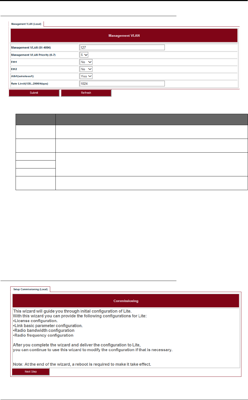
FIGURE 5. Management VLAN
2.2.4 Setting the radio parameters
This operation should be done from both the passive and control ends of the link and channel selec-
tions should match to ensure the link comes up when properly aligned. Before setting the radio
parameters, ensure that the correct radio standard is licensed for the geographic location where the
radio is to be installed. For example: FCC for USA or Canada, ETSI for Europe and Asia, etc.
It is also important to verify that the correct maximum speed required is licensed, as per the link
design specified for the radio in this location.
Steps
1. Go to Setup > Commissioning tab (see Figure 6) and click Next Step.
FIGURE 6. Step 1
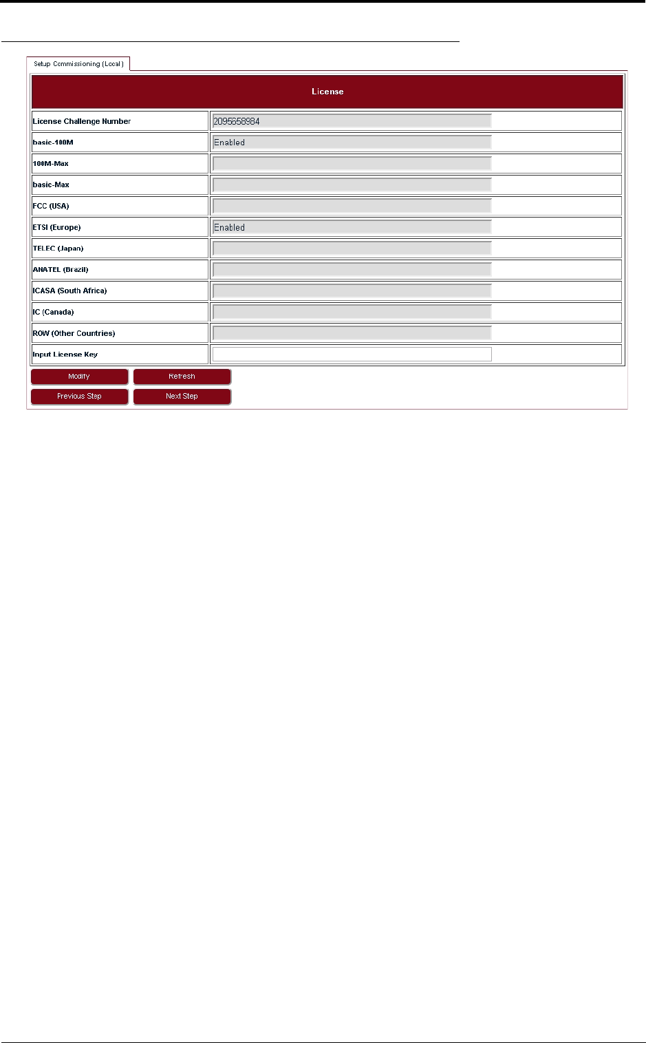
2. Input the license key and click Modify. Click Refresh to make sure of the configuration.
TABLE 6. Management VLAN
Parameter Description
Management
VLAN
Configure the management VLAN ID for remote login. VLAN range from 51 ~ 4094.
Default: 127.
Management
VLAN Priority
Configure the management VLAN priority. Value from 0 ~ 7. Default: 6.
Eth1 If the port is to be used as a part of the management VLAN, set to Yes. If no, it means
this port is removed from the management VLAN.
Eth2
Ath1(wireless1)
Rate Limit Configure the engress and eggress rate limit for management VLAN. Value from
128Kbps ~ 2Mbps. Default: 1024Kbps.
draft
15
Commissioning
FIGURE 7. Step 2
INFO
If changing from one radio standard to another, existing license must be cleared.
Please contact DragonWave Customer Support if a new license needs to be entered to change the
radio standard or geographic location setting.
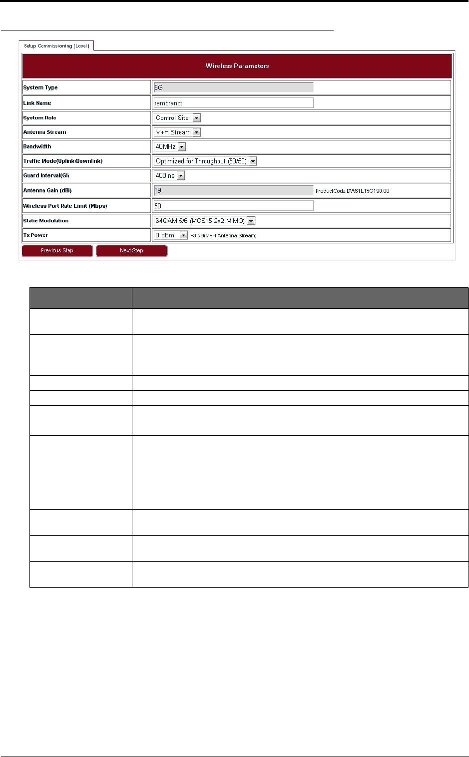
3. Set up wireless parameters according to Table 7.
draft
Commissioning
16
FIGURE 8. Step 3
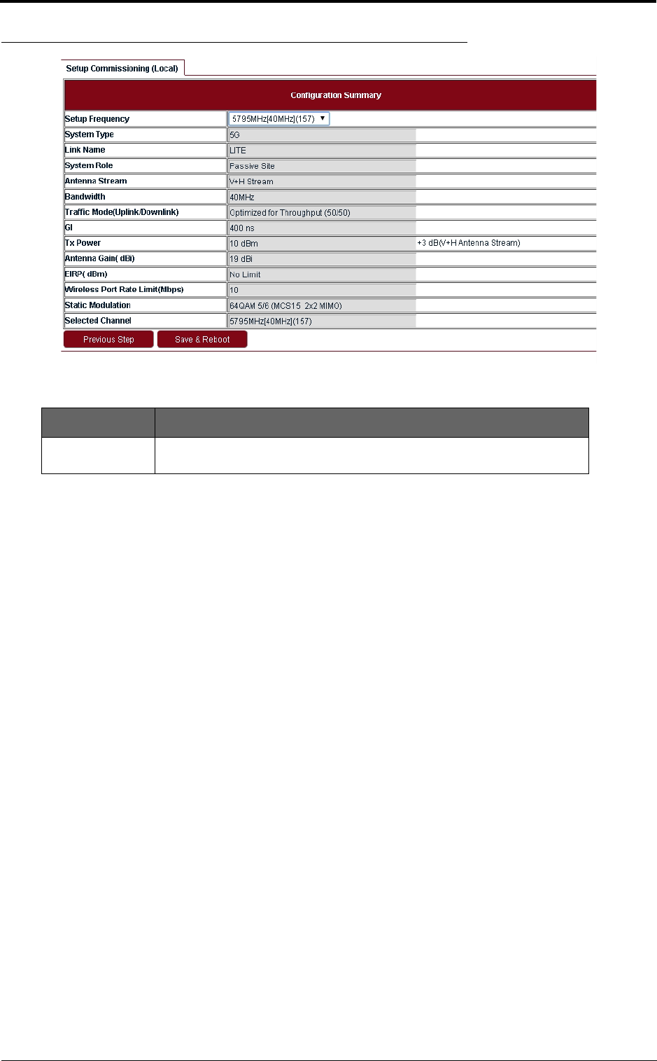
4. In Configuration Summary page, set the Setup Frequency field according to Table 9.
TABLE 7. Wireless parameters
Parameter Description
Link Name Up to 32 characters, and both numbers and characters are supported. The link
name of both Control Site and Passive Site should be the same.
System Role Control Site or Passive Site.
One end of Lite should be configured as the Control Site, and the other end the
Passive Site.
Antenna Stream V+H Stream supported.
Bandwidth 40 MHz or 20MHz.
Traffic Mode (Uplink/
Downlink)
50/50
For 50/50, the uplink and downlink have the same bandwidth.
Guard Interval 400 ns or 800 ns.
If the maximum multi-path delay spreads more than 400 ns, we suggest to use
800 ns. Leaving the guard interval at 400 ns (the default) works in most applica-
tions. For installations where the link is over long stretches of water, or non-line of
sight applications with lots of multi-path signals, selecting 800 ns guard interval
can improve the performance.
Wireless Port Rate
Limit
Rate limit on Wireless port. It will only take effect while the value is lower than the
Wireless Throughput.
Static Modulation If ACM is disabled, Lite will use Static Modulation as Tx side modulation. This is
the modulation selected for this link and will not change unless ACM is enabled.
Tx Power Tx power on each radio. Limited by EIRP. This rate limit is automatically assigned
based on the modulation selected.
draft
17
Commissioning
FIGURE 9. Step 6
5. Check all the configurations in Figure 9 and click Save & Reboot so that Lite will restart
and run under new configurations.
TABLE 8. Configuration summary
Parameter Description
Setup Frequency The setup frequency is the initial frequency to be used when the link is set
up.
draft

Commissioning
18
draft
19
System configuration
3 System configuration
3.1 System home
Go to the Home page to set the parameters.
FIGURE 10. System Home
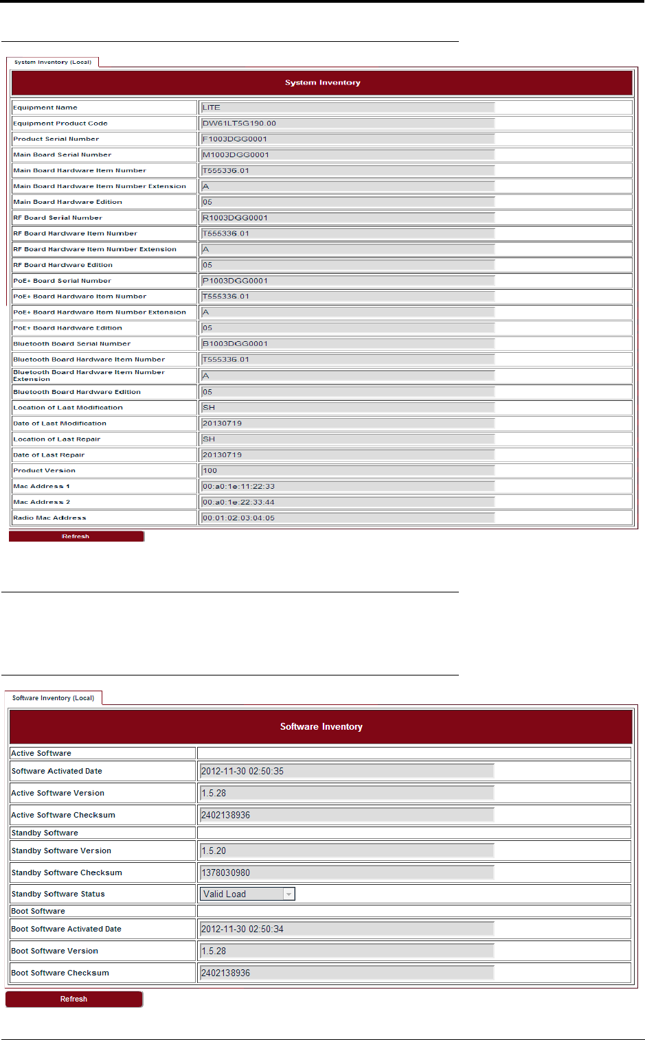
3.2 System inventory
Go to Configuration > System > System Inventory page.
draft
System configuration
20
FIGURE 11. System inventory
3.3 Software inventory
Go to Configuration > System > Software Inventory page.
FIGURE 12. Software inventory
draft
21
System configuration
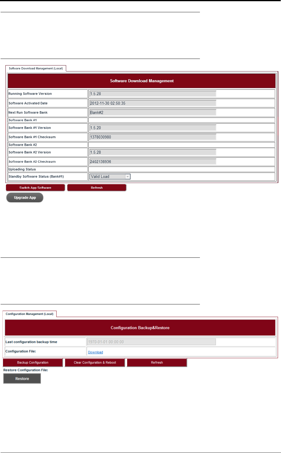
3.4 Software management
Steps
1. Go to Configuration > System > Software Management page.
FIGURE 13. Software download management
2. Click Upgrade App and go to the right folder path to open the target software.
3. Click Switch App Software, confirm the Next Run Software Bank is switched correctly.
4. Click Reboot System. After reboot, Lite would start up with the new software.
3.5 Configuration management
Steps
1. Go to Configuration > System > Configuration Management page.
FIGURE 14. Configuration backup & restore
2. Click Backup Configuration and click the Download link to download the backup configu-
ration file.
3. Click Clear Configuration & Reboot, confirm to clear configuration and reboot.
4. Click Restore and go to the right folder path to open the target configuration file.
draft
System configuration
22
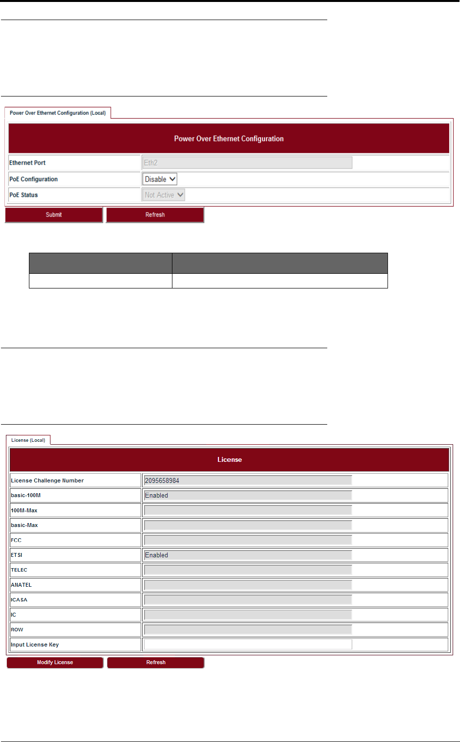
3.6 P+E output
Steps
1. Go to Configuration > System > P+E Output page.
FIGURE 15. P+E output configuration
2. Click Submit to apply the configuration.
3.7 Licensing
Steps
1. Go to Configuration > System > Licensing page.
FIGURE 16. License
2. Click Modify License to make change on the license information.
TABLE9. P+E output
Parameter Description
PoE Configuration Enable or Disable. Default: Disable.
draft
23
System configuration
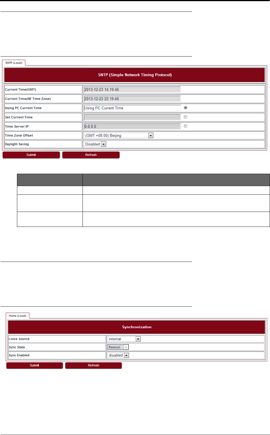
3.8 SNTP
Steps
1. Go to Configuration > System > SNTP page.
FIGURE 17. SNTP
2. To set SNTP, fill out all the parameters and click Submit.
3.9 Synchronization
Steps
1. Go to Configuration > System > Synchronization page.
FIGURE 18. Synchronization
2. To set Synchronization, fill out all the parameters and click Submit.
TABLE10. SNTP
Parameter Description
Time Server IP It is used to get SNTP time from Time Server.
Time Zone Offset Configure the NE time zone when Time Server is configured.
Values are from -12 ~ +13.
Daylight Saving Configure the NE daylight saving when Time Server is configured. Value is
Enabled or Disabled.
draft

System configuration
24
draft
25
Wireless radio configuration
4 Wireless radio configuration
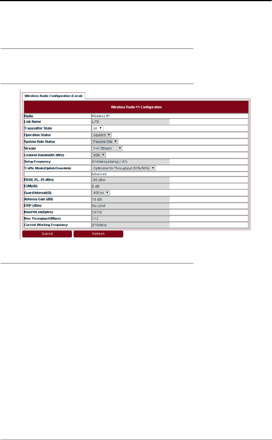
4.1 Wireless radio #1 configuration
Go to Configuration > Wireless Radio > Wireless page to see the Wireless Radio Configuration.
FIGURE 19. Wireless radio #1 configuration
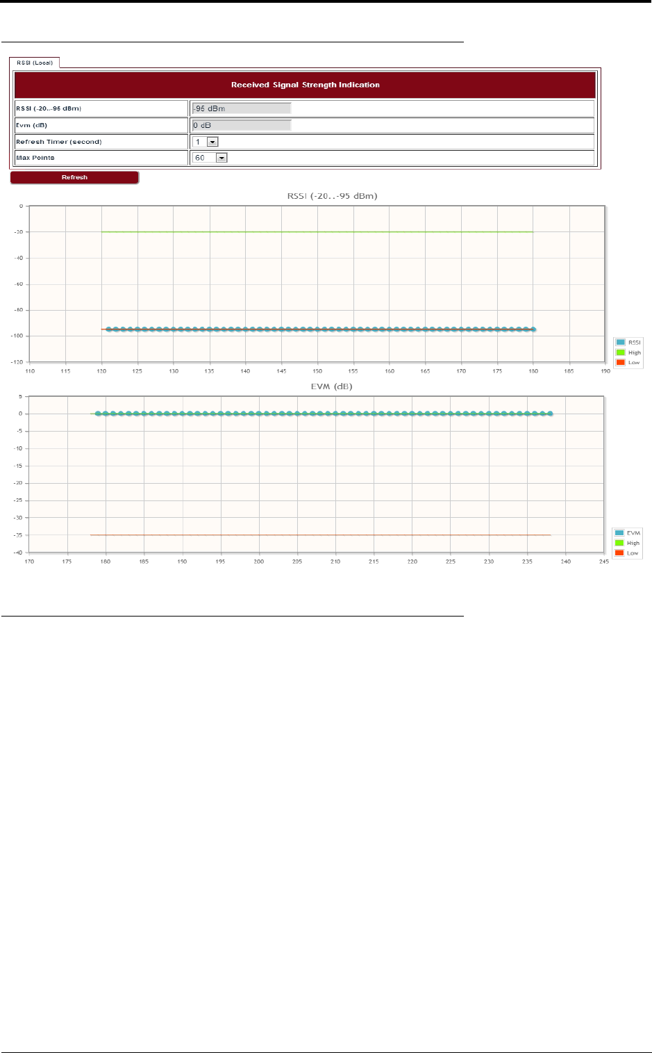
4.2 Received Signal Strength Indication
Go to Configuration > Wireless Radio > RSSI page to see the Received Signal Strength Indica-
tion.
draft
Wireless radio configuration
26
FIGURE 20. RSSI
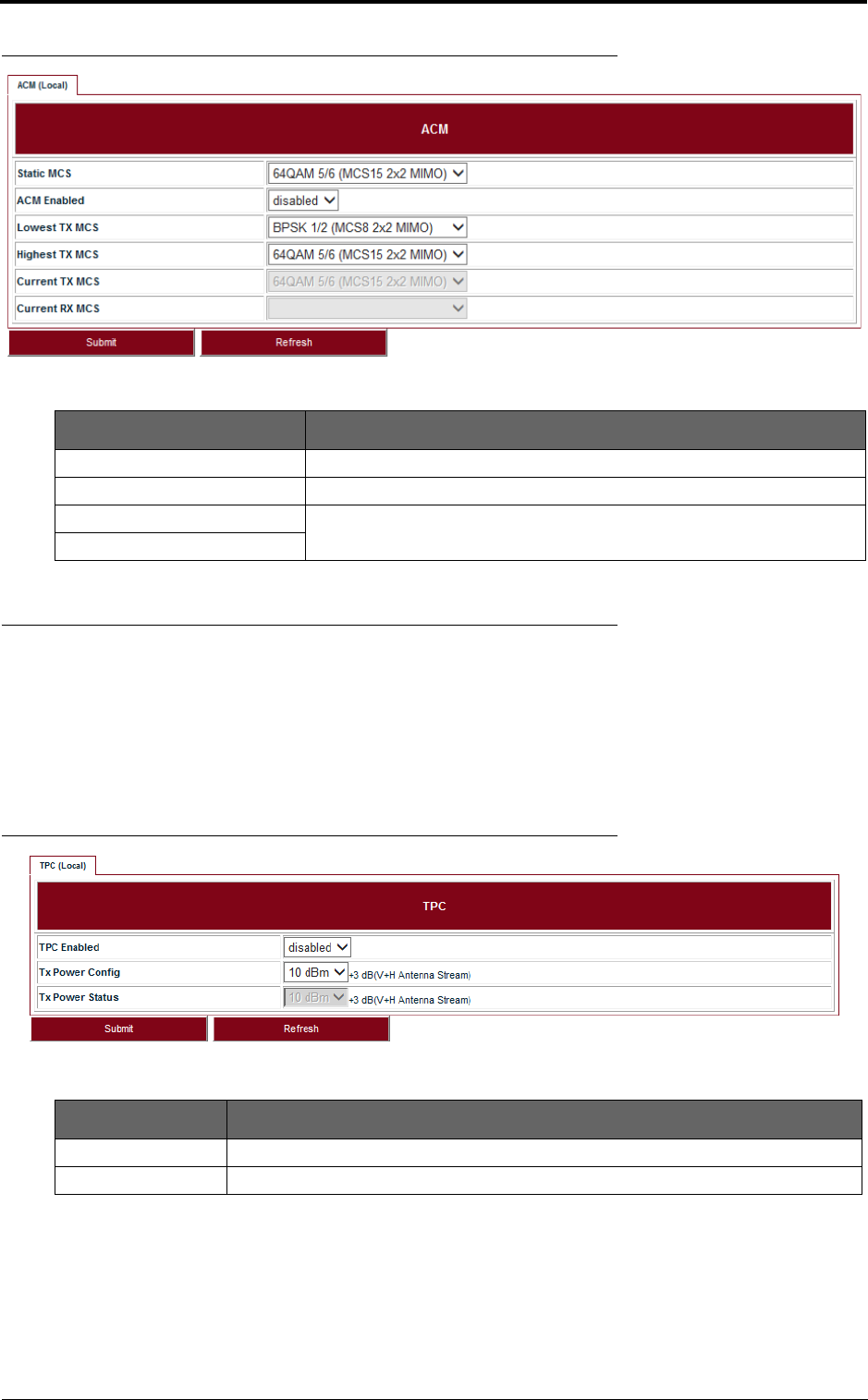
4.3 Modulation and ACM
Go to Configuration > Wireless Radio > ACM page to set the modulation and ACM parameters.
draft
27
Wireless radio configuration
FIGURE 21. ACM
4.4 Tx power and Adaptive Transmit Power Control (ATPC)
Adaptive Transmit Power Control (ATPC) allows a Lite system to adjust its transmit power to com-
pensate for far end signal loss caused by changes in atmospheric conditions, e.g., heavy rain. ATPC
maintains the RSSI at the ATPC threshold, which is system mode dependent, and adjusts the trans-
mit power as necessary in order to maintain the ATPC threshold during fading conditions.
Go to Configuration > Wireless Radio > TPC page.
FIGURE 22. TPC
TABLE 11. ACM
Parameter Description
Static MCS The Tx modulation when ACM is disabled.
ACM Enabled Enabled or Disabled.
Lowest TX MCS MCS range for Lite, when ACM is enabled.
Highest TX MCS
TABLE 12. TPC
Parameter Description
ATPC Enabled Enabled or Disabled. Default: Disabled.
Tx Power Config Set the Tx Power on each chain, it is limited by local regulations.
draft

Wireless radio configuration
28
draft
29
Ethernet configuration
5 Ethernet configuration
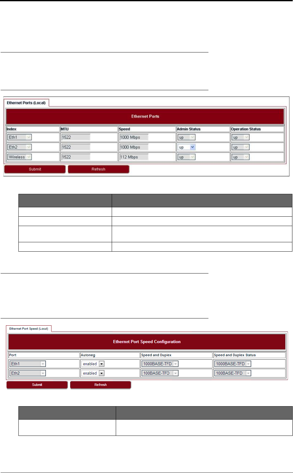
5.1 Ports
Go to Configuration > Ethernet > Port > Ports page to set the Ethernet Ports.
FIGURE 23. Ethernet ports
5.2 Speed
Go to Configuration > Ethernet > Port > Speed page to set the Ethernet Port Speed Configura-
tion.
FIGURE 24. Ethernet port speed configuration
TABLE 13. Ethernet ports
Parameter Description
MTU The MTU of Lite is a fixed value: 1522.
Speed It shows the current speed of the port.
Admin Status By default the Admin Status of all ports is up, only the Admin Status of
Eth2 can be set to down.
Operation Status It displays the current port status which can be up or down.
TABLE 14. Ethernet port speed configuration
Parameter Description
Autoneg The autonegotiation is enabled by default. It can be configured to
disabled.
draft
Ethernet configuration
30
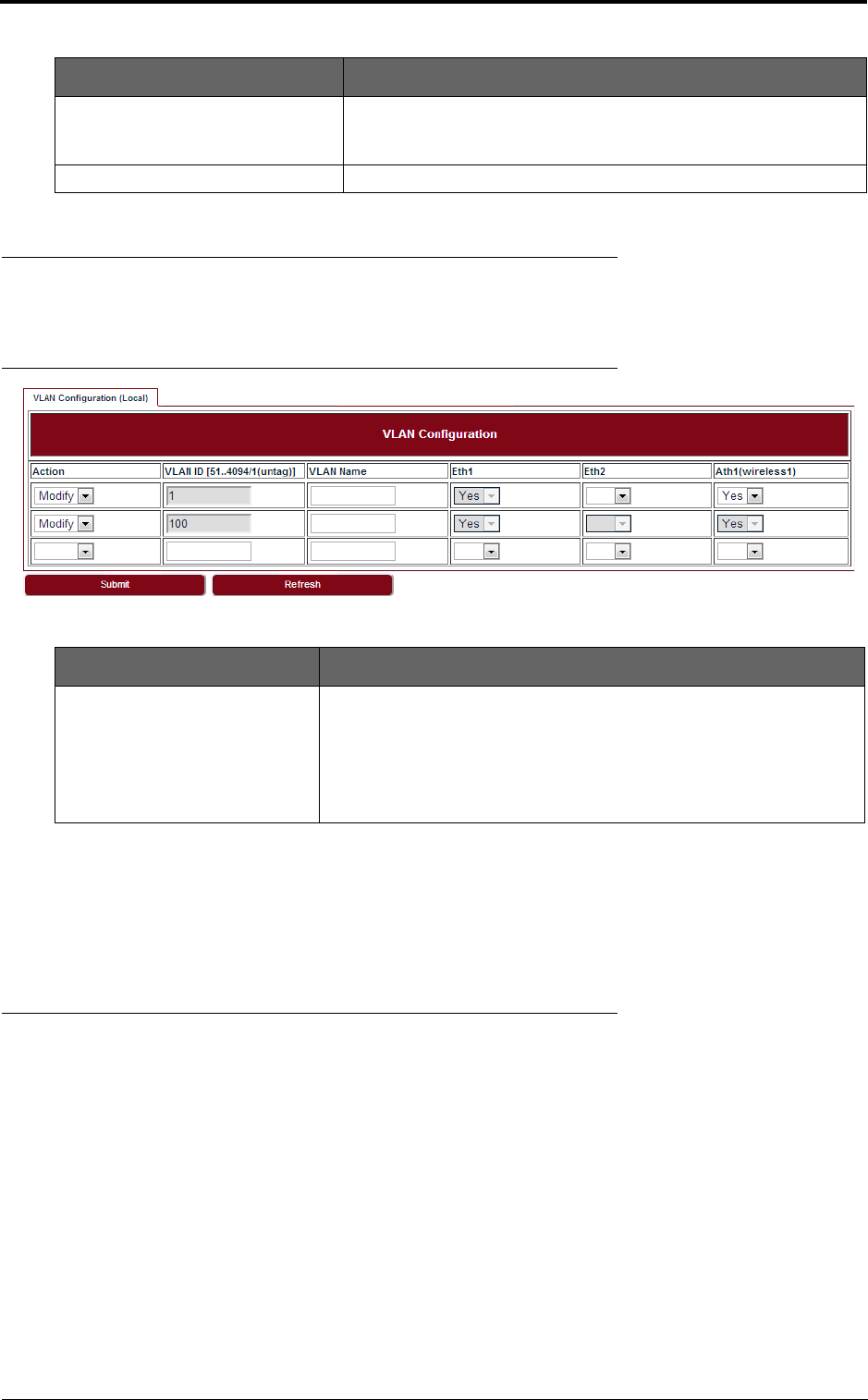
5.3 VLAN management
Go to Configuration > Ethernet > VLAN > VLAN page to set the VLAN Configuration.
FIGURE 25. VLAN configuration
To create a VLAN, select Create in the Action drop-down list and fill out all the parameters and click
Submit.
Similarly, a VLAN can be modified or deleted by selecting Modify or Delete in the Action drop-down
list and click Submit.
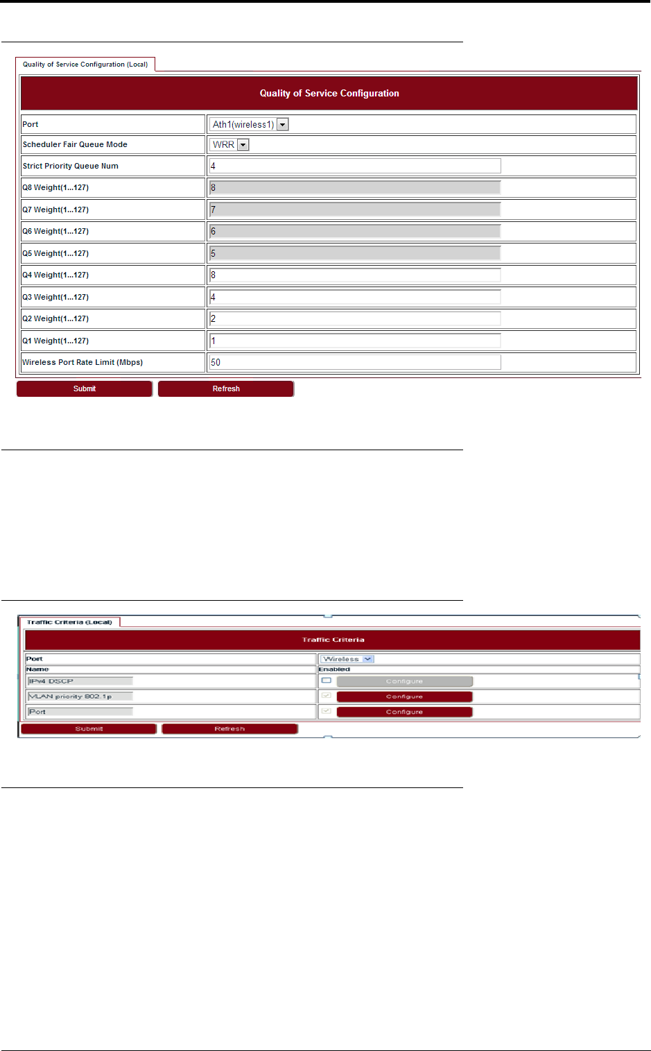
5.4 QoS scheduler
Go to Configuration > Ethernet > QoS > QoS page to set the QoS Scheduler. Three scheduling
modes are supported:
• Strict Priority
• Weighted Round Robin (WRR)/Deficit Weighted Round Robin (DWRR)
• Strict Priority + WRR/DWRR
While the Strict Priority Queue Number is 8, it is SP mode. While the number is less than 8, it is SP
+ WRR or SP + DWRR two scheduler modes.
The default scheduling mode is SP+WRR, 4 SP queue + 4 WRR queue, the weight for Q4-Q1 are
8:4:2:1. The Wireless Port Rate Limit will only take effect when its value is lower than the Wireless
Throughput.
Speed and Duplex Under the autoneg disabled status, speed and duplex of port can be
configured, only 100Base-THD, 100Base-TFD and 1000Base-TFD
can be supported.
Speed and Duplex Status It displays the current status of Ethernet speed and duplex.
TABLE 15. VLAN configuration
Parameter Description
VLAN ID The VLAN 1 is a special VLAN used to forward untagged traffic and for
local management, it is a permanent VLAN and cannot be deleted. It
includes Eth1 and Wireless port by default.
The available values of VLAN ID are 51 ~ 4094, 2 ~50 are reserved by
system. They are all tagged VLAN. The maximum number of VLANs is
48.
TABLE 14. Ethernet port speed configuration
Parameter Description
draft
31
Ethernet configuration
FIGURE 26. Quality of Service Configuration
5.5 Traffic criteria
Go to Configuration > Ethernet > QoS > Traffic Criteria page to set the Traffic Criteria. The Port
and VLAN priority 802.1p are the default traffic criteria for tagged traffic and untagged traffic. And
they cannot be disabled. The IPv4 DSCP can be enabled if it is necessary, and it is prior to other cri-
teria if the DSCP-802.1p mapping was configured in the list. Default setting is with IPv4 DSCP crite-
ria disabled with the exclusion of the VLAN priority 802.1p and Port criteria that is always enabled.
FIGURE 27. Traffic Criteria
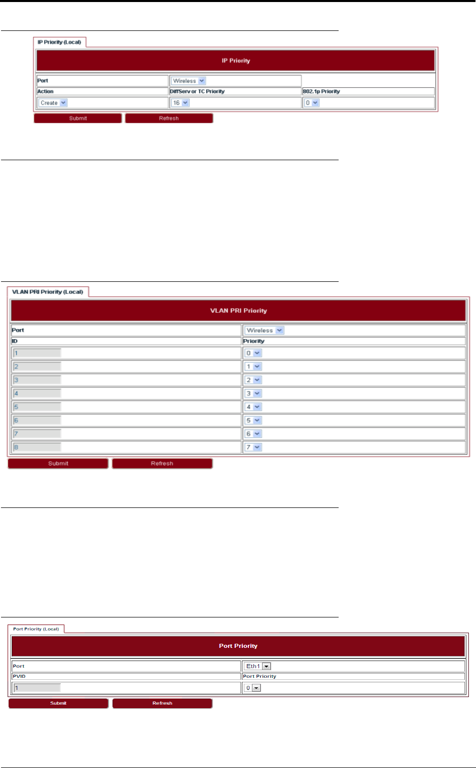
5.6 IP priority
Go to Configuration > Ethernet > QoS > IP Priority page to set the IP Priority. Frames whose Diff-
Serv or TC Priority does not belong to any entry of the IPv4 DSCP priority table and which are
tagged will be processed using VLAN PRI 802.1p priority, or which are untagged will be processed
using Port criteria. Up to 64 values (between 0 and 63) can be configured by NMS.
draft
Ethernet configuration
32
FIGURE 28. IP priority
5.7 VLAN PRI priority
Go to Configuration > Ethernet > QoS > Vlan PRI Priority page to set the VLAN PRI Priority.
When VLAN priority field criterion is enabled, it is possible to associate an output priority to each one
of VLAN priority field values. Classification for single tagged frames (802.1Q compliant) is based on
VLAN Priority. For untagged frame, the VLAN priority is set to 0. Classification for Q-in-Q frames
(both 802.1ad compliant and proprietary formats) is based on outer VLAN Priority. The eight default
priority values for the VLAN priority fields can be configured.
FIGURE 29. VLAN PRI priority
5.8 Port priority
Go to Configuration > Ethernet > QoS > Port Priority page to set the Port Priority. Port priority
field criterion is enabled by default, it cannot be disabled. It is used to address the untagged frames
which are not IPv4 frames or IPv4 frames but not match the DSCP and 802.1p mapping in IPv4
DSCP criteria. For untagged frame, the VLAN priority is set to 0 by default. The value for Port Prior-
ity can be set in range of 0-7.
FIGURE 30. Port priority
draft

33
Ethernet configuration
5.9 Aging time
Go to Configuration > Ethernet > FDB > Aging Time page to set the Ethernet Aging Time.
FIGURE 31. Aging time
5.10 Static Unicast FDB
Go to Configuration > Ethernet > FDB > Static Unicast FDB page to set the Static Unicast FDB.
FIGURE 32. Static Unicast FDB
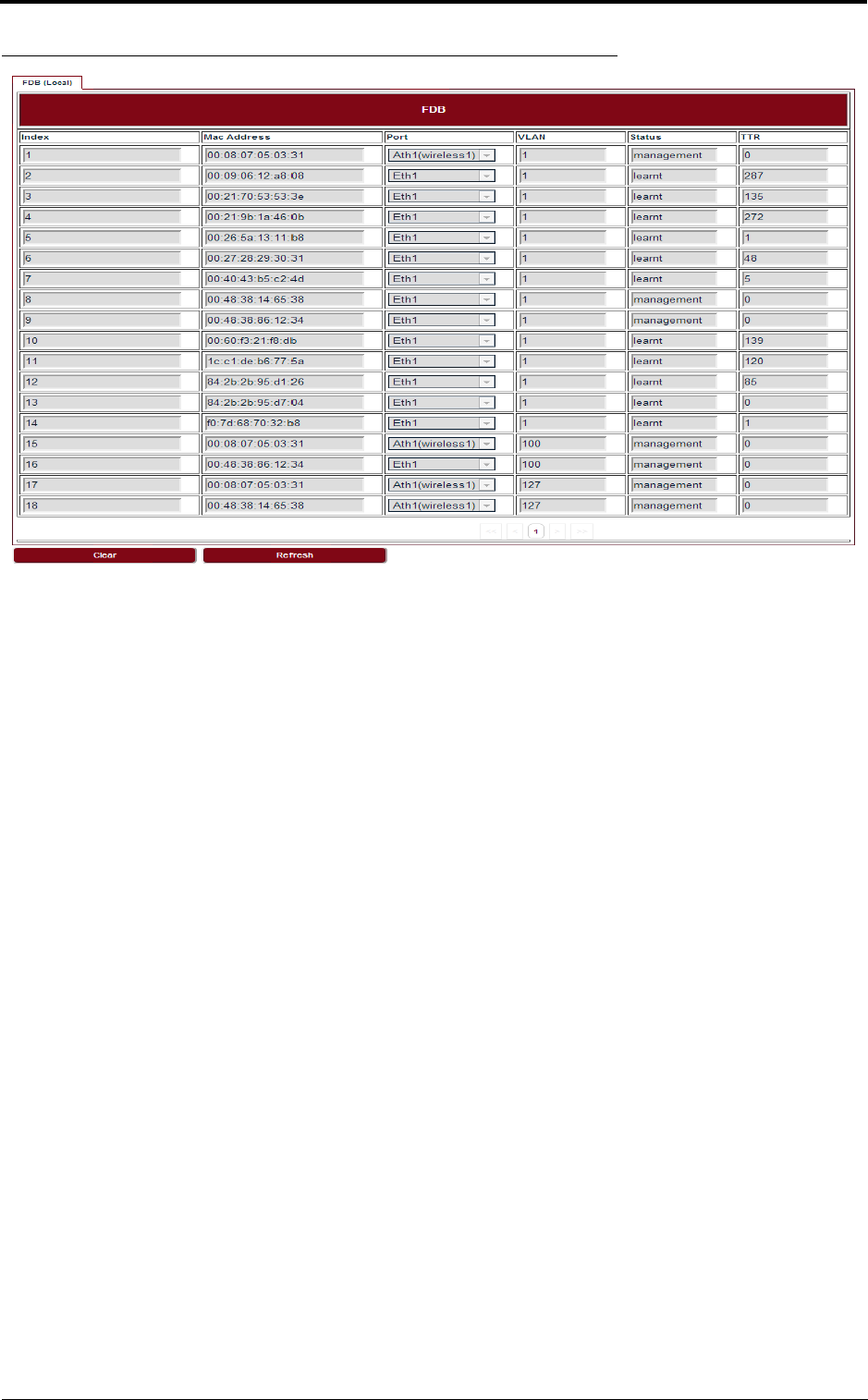
5.11 All FDB
Go to Configuration > Ethernet > FDB > All FDB page to see all FDB. The management status in
FDB means system reserved MAC address, they were used by internal port.The learnt status is
dynamic MAC address. TTR is the remaining time to be removed from FDB list. For management
status MAC address, it is always zero.
TABLE 16. Aging time
Parameter Description
Aging Time The values of aging time are 0/10-1000000s. If 0 was configured, it
means Lite does not learn MAC address.
draft
Ethernet configuration
34
FIGURE 33. All FDB
draft
35
Management
6 Management
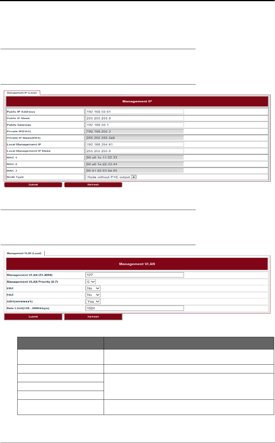
6.1 IP
Go to Configuration > Management > IP page to set the Management IP.
FIGURE 34. Management IP
6.2 Management VLAN
Go to Configuration > Management > Management VLAN page to set the Management VLAN.
FIGURE 35. Management VLAN
TABLE 17. Management VLAN
Parameter Description
Management VLAN Configure the management VLAN ID for remote login. Values are 51 ~
4094. Default: 127.
Management VLAN Priority Configure the management VLAN priority. Values are 0 ~ 7. Default: 6.
Eth1 Configure which port is in management VLAN.
Eth2
Ath1 (wireless1)
Rate Limit It is engress and eggress rate limit for management VLAN. Values are
128Kbps ~ 2Mbps. Default: 1024Kbps.
draft
Management
36
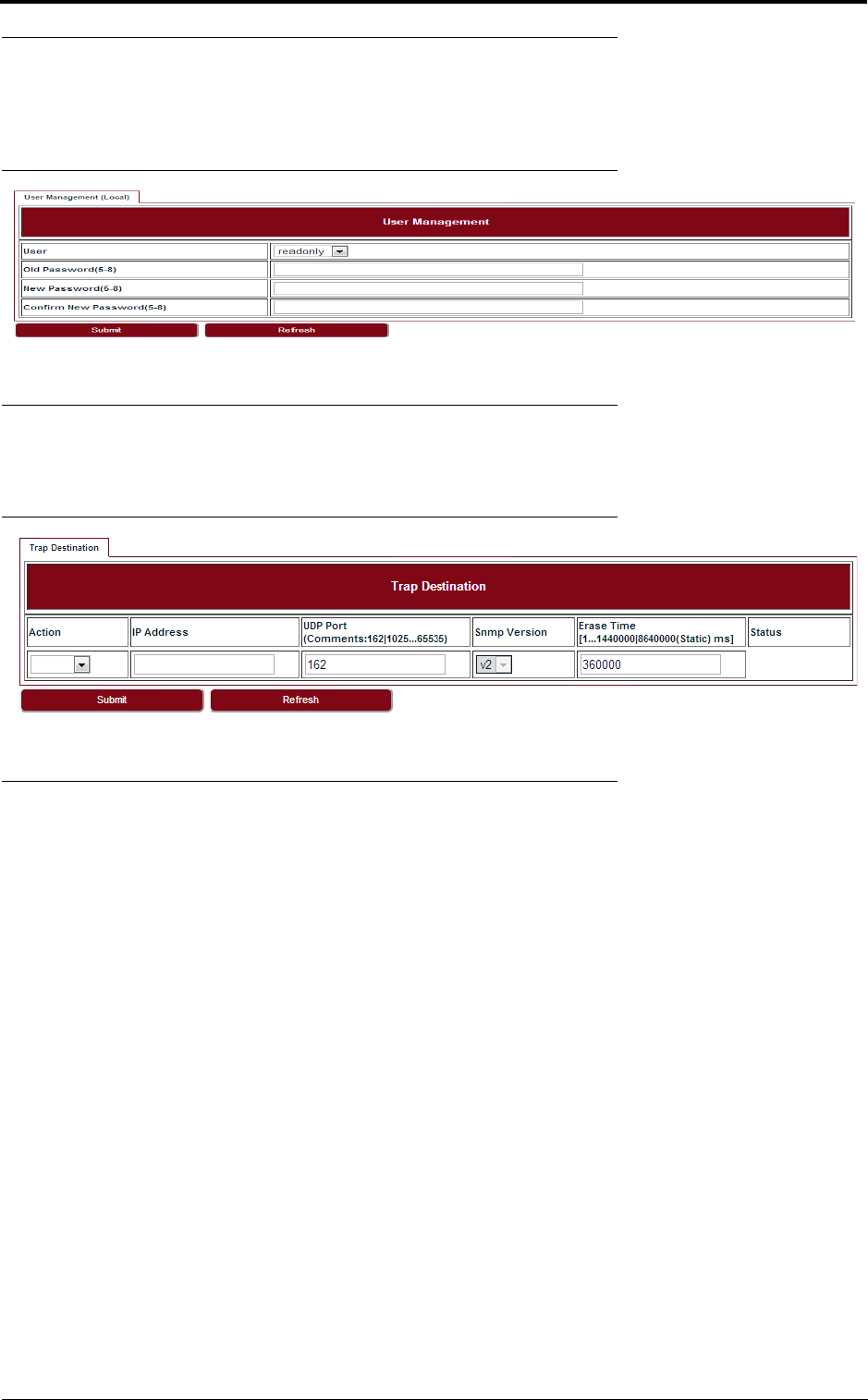
6.3 SNMP
Go to Configuration > Management > SNMP page to change the User Name and Password.
Default User Name is energetic, default Password is wireless.
FIGURE 36. User management
6.4 Trap
Go to Configuration > Management > Trap page to set the Trap Destination parameters.
FIGURE 37. Trap
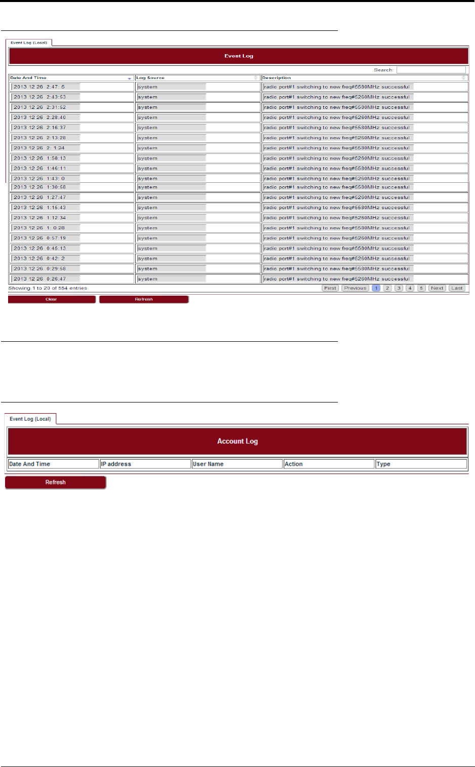
6.5 Event log
Go to Configuration > Management > Event Log page to see all the event logs.
draft
37
Management
FIGURE 38. Event log
6.6 Account log
Go to Configuration > Management > Account Log page to see all the account logs.
FIGURE 39. Account log
draft

Management
38
draft
39
Alarms
7 Alarms
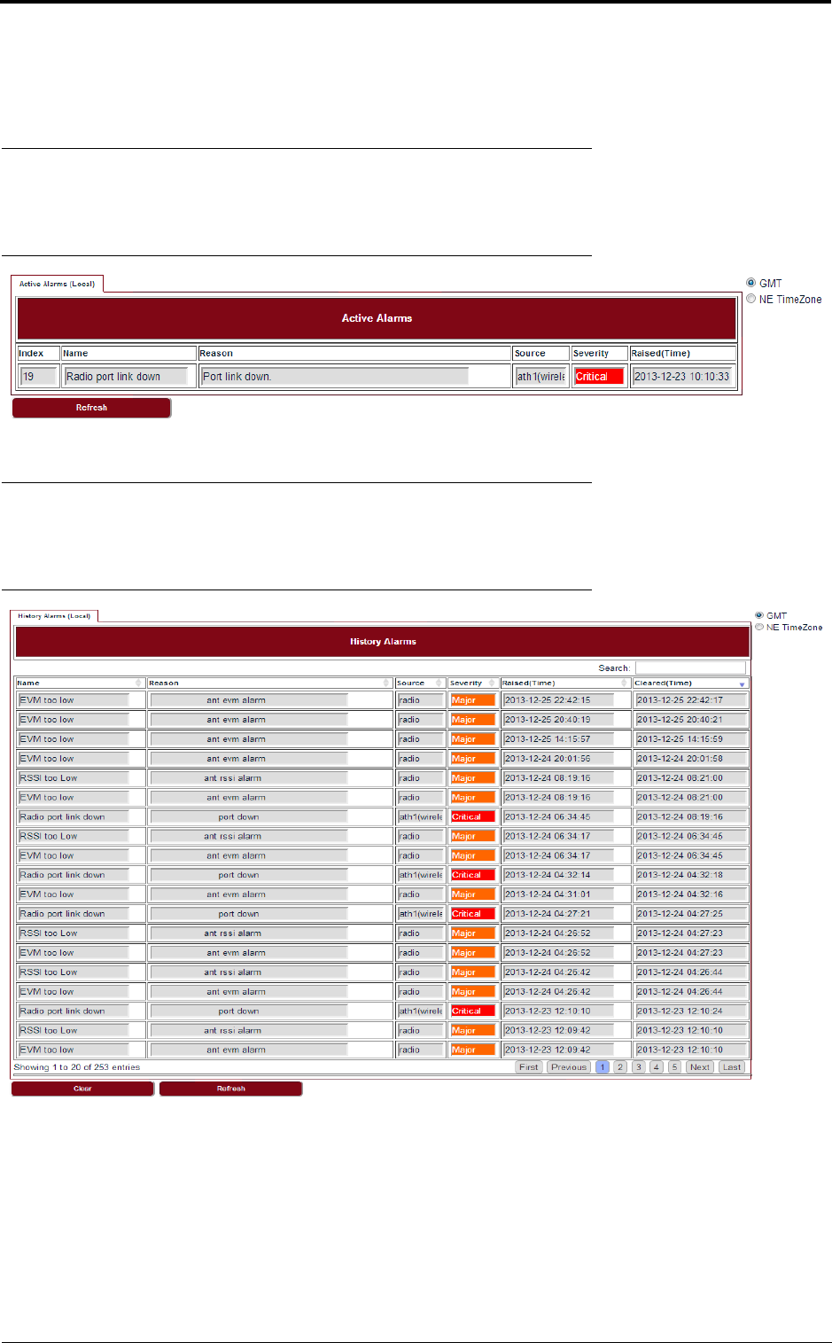
7.1 Active alarms
Go to Alarms > Active Alarms page to see the current alarm list.
FIGURE 40. Active alarms
7.2 History alarms
Go to Alarms > History Alarms page to see the history alarm list.
FIGURE 41. History alarms
draft

Alarms
40
draft
41
Performance
8 Performance
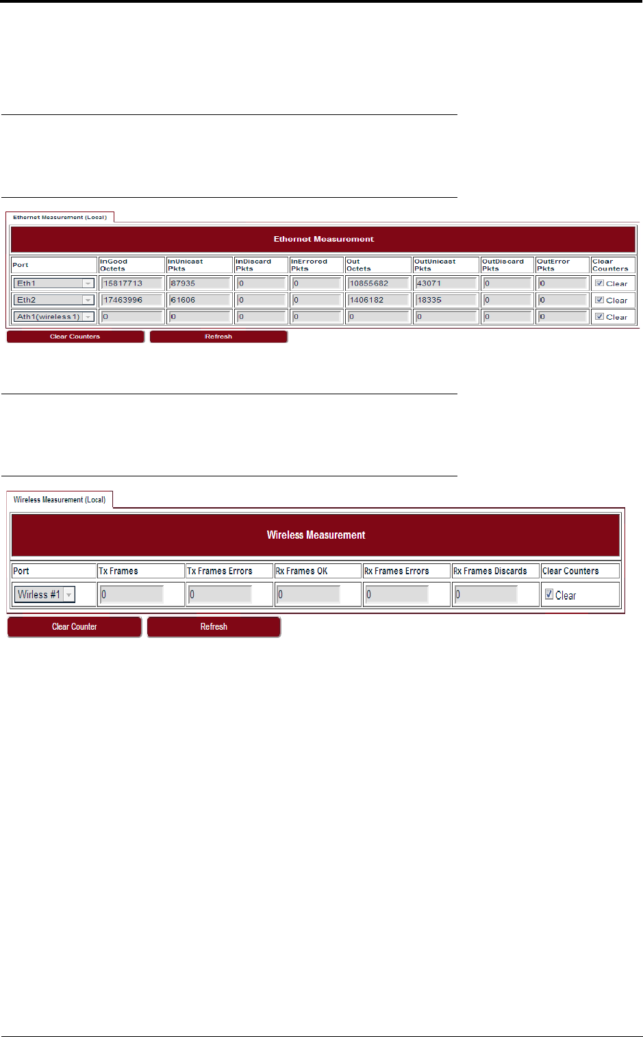
8.1 Ethernet
Go to Performance > Ethernet page to see the Ethernet measurement.
FIGURE 42. Ethernet
8.2 Wireless
Go to Performance > Wireless page to see the Wireless measurement.
FIGURE 43. Wireless
draft

Performance
42
draft
43
Diagnostics
9 Diagnostics
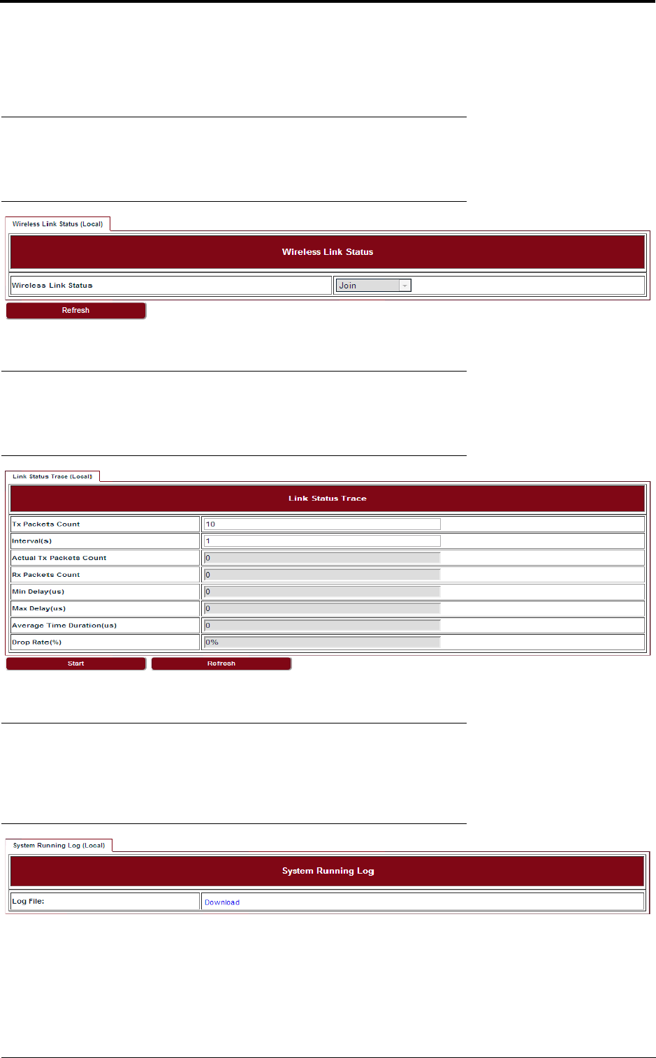
9.1 Link status
Go to Diagnostics > Link Status page to see the Wireless link status.
FIGURE 44. Link status
9.2 Link status trace
Go to Diagnostics > Link Status Trace page to see the link status trace.
FIGURE 45. Link status trace
9.3 System running log
Go to Diagnostics > System Running Log page, click on “Download” to see the system running
log.
FIGURE 46. System running log
draft

Diagnostics
44
draft

45
About
10 About
Go to the About page to see the information about the Link Viewer release.
FIGURE 47. About Link Viewer
draft

About
46
draft

Operating Channel Declaration
Operating Channel List
Channels for 20MHz Channel Bandwidth
Channel
Frequency
Channel
Frequency
Channel
Frequency
149
5745 MHz
153
5765 MHz
157
5785 MHz
161
5805 MHz
165
5825 MHz
N/A
N/A
Channels for 40MHz Channel Bandwidth
Channel
Frequency
Channel
Frequency
Channel
Frequency
151
5755 MHz
159
5795 MHz
N/A
N/A
Note: There is no weather radar frequency band (5600-5650MHz) for the Microwave
Outdoor Unit.

43
Declaration of Conformity for RF Exposure
This microwave outdoor unit product has been found to be compliant to the
requirements set forth in CFR 47Section 1.1307 addressing RF Exposure from radio
frequency devices as defined in Evaluating Compliance with FCC Guidelines for
Human Exposure to Radio Frequency Electromagnetic Fields.
Antennas with less than 23.5 dBi gain should be located at a minimum of 39.03 cm in
more from the body of all persons.
Calculation Formula: Pd = (Pout*G)/(4*pi*r2)
Where
Pd = power density in mW/cm2
Pout = output power to antenna in mW
G = gain of antenna in linear scale
Pi = 3.1416
r = distance between observation point and center of the radiator in cm
Pd is the limit of MPE, 1mW/cm².
If we know the maximum gain of the antenna and the total power input to the antenna,
through the calculation, we will know the distance r where the MPE limit is reached.
LITE, R1.0, Operation and Maintenance Guide, Issue 1
Federal Communications Commission (FCC) Interference Statement
This equipment has been tested and found to comply with the limits for a Class B digital device,
pursuant to Part 15 of the FCC Rules.
These limits are designed to provide reasonable protection against harmful interference in a
residential installation. This equipment generate, uses and can radiate radio frequency energy
and, if not installed and used in accordance with the instructions, may cause harmful
interference to radio communications.
However, there is no guarantee that interference will not occur in a particular installation. If this
equipment does cause harmful interference to radio or television reception, which can be
determined by turning the equipment off and on, the user is encouraged to try to correct the
interference by one of the following measures:
Reorient or relocate the receiving antenna.
Increase the separation between the equipment and receiver.
Connect the equipment into an outlet on a circuit different from that to which the receiver is
connected.
Consult the dealer or an experienced radio/TV technician for help.
This device complies with Part 15 of the FCC Rules. Operation is subject to the following two
conditions:
(1) This device may not cause harmful interference, and (2) this device must accept any
interference received, including interference that may cause undesired operation.
FCC Caution: Any changes or modifications not expressly approved by the party responsible
for compliance could void the user’s authority to operate this equipment.
RF exposure warning
This equipment complies with FCC radiation exposure limits set forth for an uncontrolled
environment.
This equipment must be installed and operated in accordance with provided instructions and
the antenna(s) used for this transmitter must be installed to provide a separation distance of at
least 39.03 cm from all persons and must not be collocated or operating in conjunction with any
other antenna or transmitter.