Draytek AP903 Dual Band Security Firewall User Manual Vigor2100V QIG
Draytek Corporation Dual Band Security Firewall Vigor2100V QIG
Draytek >
Contents
- 1. Vigor2122 User Manual
- 2. VigorAP-903 User Manual
Vigor2122 User Manual
i
ii
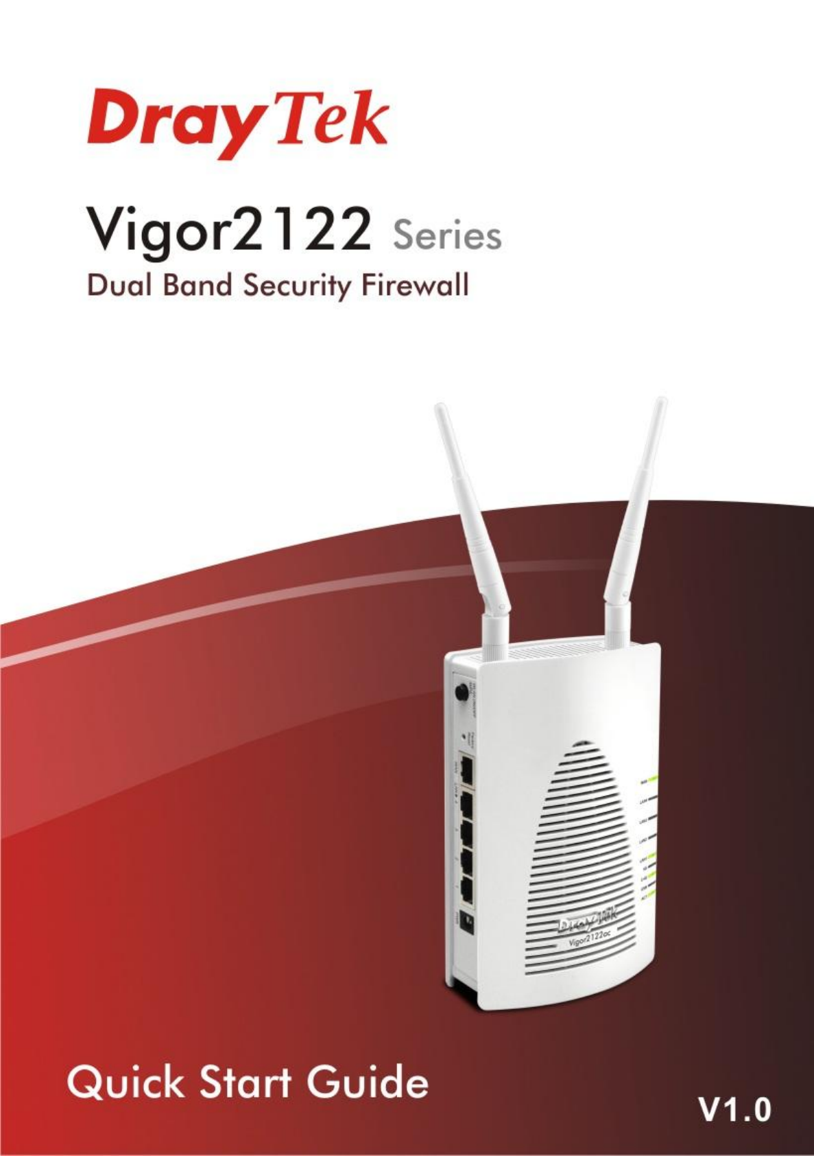
Vigor2122 Series
Dual Band Security Firewall
Quick Start Guide
Version:1.0
Firmware Version: V3.8.9_RC1
(For future update, please visit DrayTek web site)
Date: May 30, 2018

i
Intellectual Property Rights (IPR) Information
Copyrights
© All rights reserved. This publication contains information that is protected
by copyright. No part may be reproduced, transmitted, transcribed, stored in
a retrieval system, or translated into any language without written permission
from the copyright holders.
Trademarks
The following trademarks are used in this document:
Microsoft is a registered trademark of Microsoft Corp.
Windows, Windows 95, 98, Me, NT, 2000, XP, Vista, 7, 8 and
Explorer are trademarks of Microsoft Corp.
Apple and Mac OS are registered trademarks of Apple Inc.
Other products may be trademarks or registered trademarks of
their respective manufacturers.
Safety Instructions and Approval
Safety
Instructions
Read the installation guide thoroughly before you set up the router.
The router is a complicated electronic unit that may be repaired
only be authorized and qualified personnel. Do not try to open or
repair the router yourself.
Do not place the router in a damp or humid place, e.g. a bathroom.
Do not stack the routers.
The router should be used in a sheltered area, within a
temperature range of +5 to +40 Celsius.
Do not expose the router to direct sunlight or other heat sources.
The housing and electronic components may be damaged by direct
sunlight or heat sources.
Do not deploy the cable for LAN connection outdoor to prevent
electronic shock hazards.
Keep the package out of reach of children.
When you want to dispose of the router, please follow local
regulations on conservation of the environment.
Warranty
We warrant to the original end user (purchaser) that the router will be free
from any defects in workmanship or materials for a period of two (2) years
from the date of purchase from the dealer. Please keep your purchase receipt
in a safe place as it serves as proof of date of purchase. During the warranty
period, and upon proof of purchase, should the product have indications of
failure due to faulty workmanship and/or materials, we will, at our discretion,
repair or replace the defective products or components, without charge for
either parts or labor, to whatever extent we deem necessary tore-store the
product to proper operating condition. Any replacement will consist of a new
or re-manufactured functionally equivalent product of equal value, and will
be offered solely at our discretion. This warranty will not apply if the product
is modified, misused, tampered with, damaged by an act of God, or subjected
to abnormal working conditions. The warranty does not cover the bundled or
licensed software of other vendors. Defects which do not significantly affect
the usability of the product will not be covered by the warranty. We reserve
the right to revise the manual and online documentation and to make changes
from time to time in the contents hereof without obligation to notify any
person of such revision or changes.
ii
Declaration of Conformity
Hereby, DrayTek Corporation declares that the radio equipment type Vigor2122 is in compliance with
Directive 2014/53/EU.
The full text of the EU declaration of conformity is available at the following internet address:
http://www.draytek.com.tw/ftp/Vigor2122/Document/CE/
Manufacturer: DrayTek Corp.
Address: No. 26, Fu Shing Road, HuKou Township, HsinChu Industrial Park, Hsin-Chu County,
Taiwan 303
Product: Vigor2122 Series
Frequency Information for Europe area:
2.4G WLAN
2412MHz - 2472 MHz, max. TX power: 19.95dBm
5G WLAN
5180MHz - 5700 MHz, max. TX power: 25.65dBm
Requirements in AT/BE/BG/CZ/DZ/DK/EE/FR/DE/IS/IE/IT/EL/ES/
CY/LV/LI/LT/LU/HU/MT/NL/NO/PL/PT/RO/SI/SK/TR/FI/SE/CH/
UK/HR. 5150MHz~5350MHz is for indoor use only.
This product is designed for the 2.4GHz /5GHz WLAN network throughout the EC region.
Regulatory Information
Federal Communication Commission Interference Statement
This equipment has been tested and found to comply with the limits for a Class B digital device,
pursuant to Part 15 of the FCC Rules. These limits are designed to provide reasonable protection
against harmful interference in a residential installation. This equipment generates, uses and can
radiate radio frequency energy and, if not installed and used in accordance with the instructions, may
cause harmful interference to radio communications. However, there is no guarantee that
interference will not occur in a particular installation. If this equipment does cause harmful
interference to radio or television reception, which can be determined by turning the equipment off
and on, the user is encouraged to try to correct the interference by one of the following measures:
Reorient or relocate the receiving antenna.
Increase the separation between the equipment and receiver.
Connect the equipment into an outlet on a circuit different from that to which the receiver
is connected.
Consult the dealer or an experienced radio/TV technician for help.
This device complies with Part 15 of the FCC Rules. Operation is subject to the following two
conditions:
(1) This device may not cause harmful interference, and
(2) This device may accept any interference received, including interference that may cause
undesired operation.
Caution: Any changes or modifications not expressly approved by the party responsible for
compliance could void the user's authority to operate this equipment.
The antenna/transmitter should be kept at least 20 cm away from human body.
More update, please visit www.draytek.com.
iii
T
Ta
ab
bl
le
e
o
of
f
C
Co
on
nt
te
en
nt
ts
s
1. Introduction ........................................................................................................... 1
2. Package Content .................................................................................................. 2
3. Panel Explanation ................................................................................................. 3
3.1 Vigor2122 ................................................................................................................................... 3
3.2 Vigor2122ac ............................................................................................................................... 5
4. Hardware Installation ........................................................................................... 7
4.1 Network Connection ................................................................................................................... 7
5. Software Configuration ........................................................................................ 8
6. Customer Service ............................................................................................... 18
Be a Registered Owner .................................................................................................................. 18
Firmware & Tools Updates ............................................................................................................. 18
1
1
1.
.
I
In
nt
tr
ro
od
du
uc
ct
ti
io
on
n
Vigor2122 series is a broadband router which integrates IP layer QoS, NAT
session/bandwidth management to help users control works well with large
bandwidth.
By adopting hardware-based VPN platform and hardware encryption of
AES/DES/3DES, and hardware key hash of SHA-1/MD5, the router increases the
performance of VPN greatly and offers several protocols (such as
IPSec/PPTP/L2TP) with up to 2 VPN tunnels.
The object-based design used in SPI (Stateful Packet Inspection) firewall allows
users to set firewall policy with ease. CSM (Content Security Management)
provides users control and management in IM (Instant Messenger) and P2P (Peer
to Peer) more efficiency than before. In addition, DoS/DDoS prevention and
URL/Web content filter strengthen the security outside and control inside.
Vigor2122 series supports USB interface for connecting USB printer to share
printing function, 3G/4G USB modem for network connection, or connectivity for
network FTP service.
2
2
2.
.
P
Pa
ac
ck
ka
ag
ge
e
C
Co
on
nt
te
en
nt
t
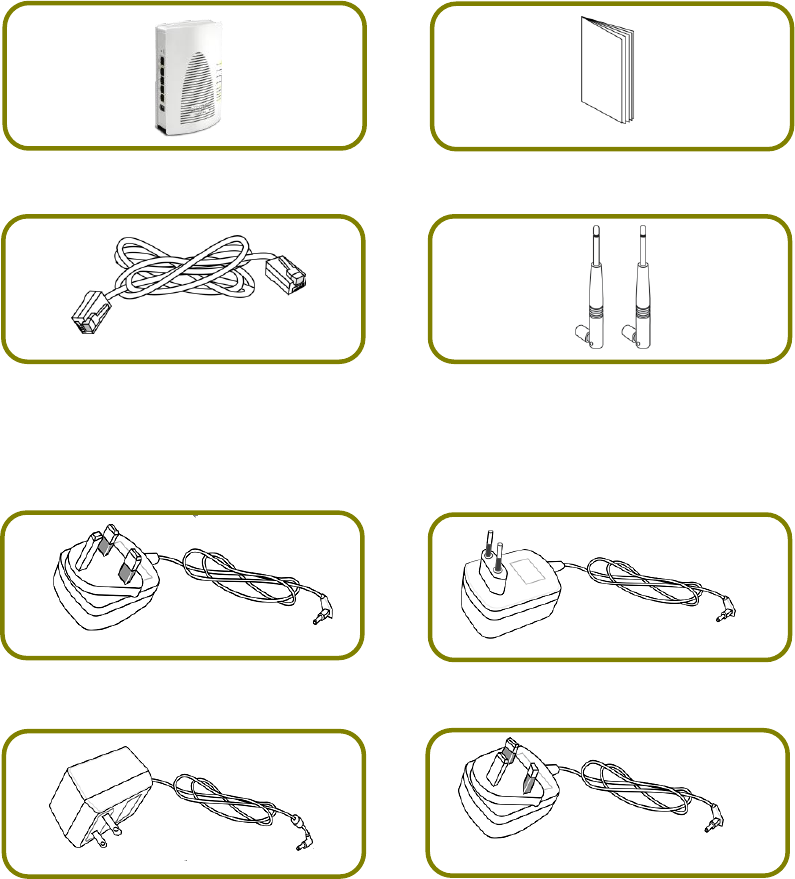
Take a look at the package content. If there is anything missed or damaged,
please contact DrayTek or dealer immediately.
Vigor Router
Quick Start Guide
RJ-45 Cat-5 Ethernet Cable
Antenna x 2 (for “ac” model)
The type of the power adapter depends on the country that the router will be
installed. * The maximum power consumption is 12 Watt.
UK-type Power Adapter
EU-type Power Adapter
USA/Taiwan-type Power Adapter
AU/NZ-type Power Adapter
3
3
3.
.
P
Pa
an
ne
el
l
E
Ex
xp
pl
la
an
na
at
ti
io
on
n
3
3.
.1
1
V
Vi
ig
go
or
r2
21
12
22
2
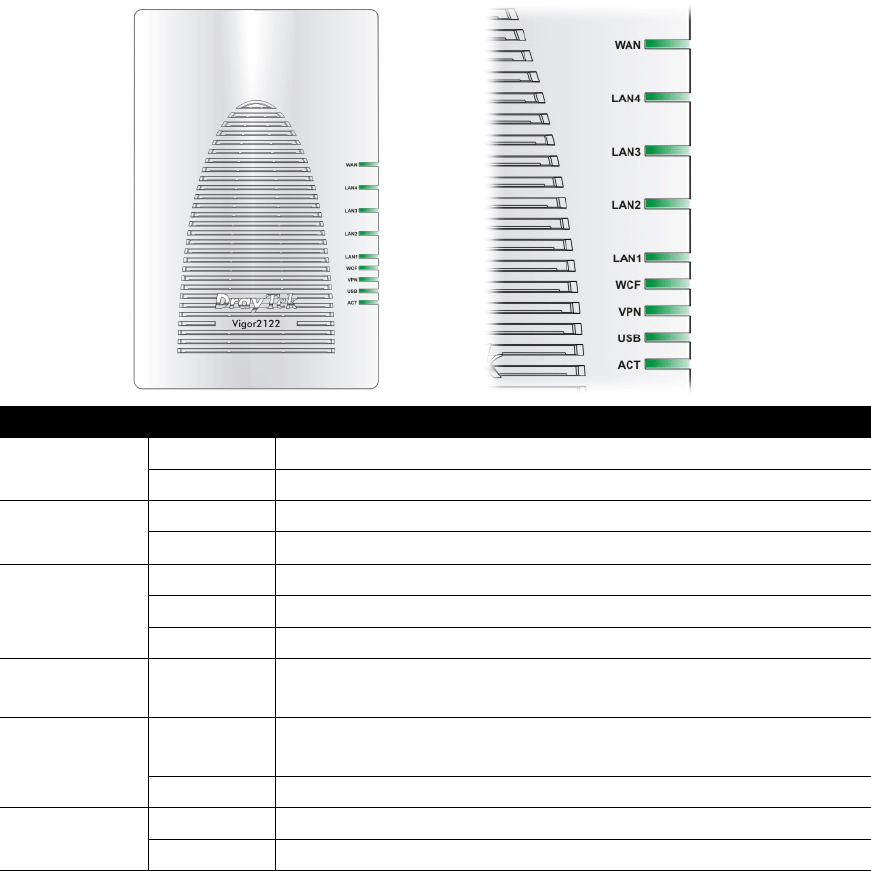
LED
Status
Explanation
ACT
Blinking
The router is powered on and running normally.
Off
The router is powered off.
USB
On
USB device is connected and ready for use.
Blinking
The data is transmitting.
VPN
On
The VPN tunnel is active.
Off
VPN service is disabled.
Blinking
Traffic is passing through VPN tunnel.
WCF
On
The Web Content Filter is active. (It is enabled from
Firewall >> General Setup).
LAN1~LAN4
On
A normal connection is through its corresponding
port.
Off
LAN is disconnected.
WAN
On
The WAN port is connected.
Blinking
It will blink while transmitting data.
4
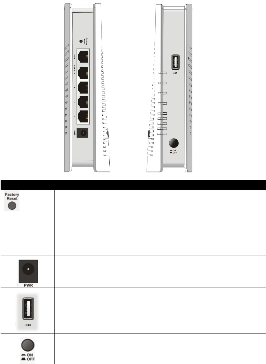
Interface
Description
Factory Reset
Restore the default settings. Usage: Turn on the router. Press
the button and keep for more than 6 seconds. Then the router
will restart with the factory default configuration.
WAN
Connector for accessing the Internet.
LAN 1- 4
Connecters for local network devices (LAN).
PWR: Connecter for a power adapter.
Connecter for a USB device (for 3G USB Modem or printer or
storage disk).
ON/OFF: Power switch.
5
3
3.
.2
2
V
Vi
ig
go
or
r2
21
12
22
2a
ac
c
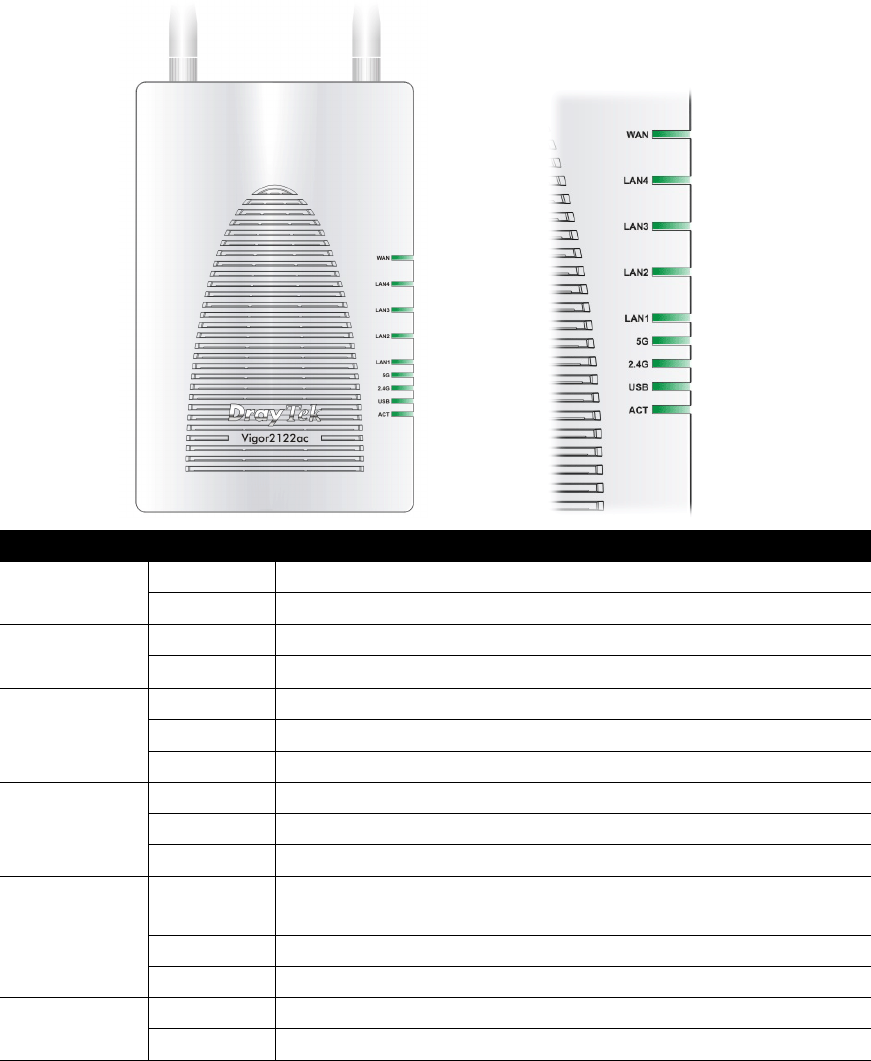
LED
Status
Explanation
ACT
Blinking
The router is powered on and running normally.
Off
The router is powered off.
USB
On
USB device is connected and ready for use.
Blinking
The data is transmitting.
2.4G
On
Wireless function is ready.
Off
Wireless function is not ready.
Blinking
Data is transmitting (sending/receiving).
5G
On
Wireless function is ready.
Off
Wireless function is not ready.
Blinking
Data is transmitting (sending/receiving).
LAN1~LAN4
On
A normal connection is through its corresponding
port.
Off
LAN is disconnected.
Blinking
Data is transmitting (sending/receiving).
WAN
On
The WAN port is connected.
Blinking
It will blink while transmitting data.
6
Interface
Description
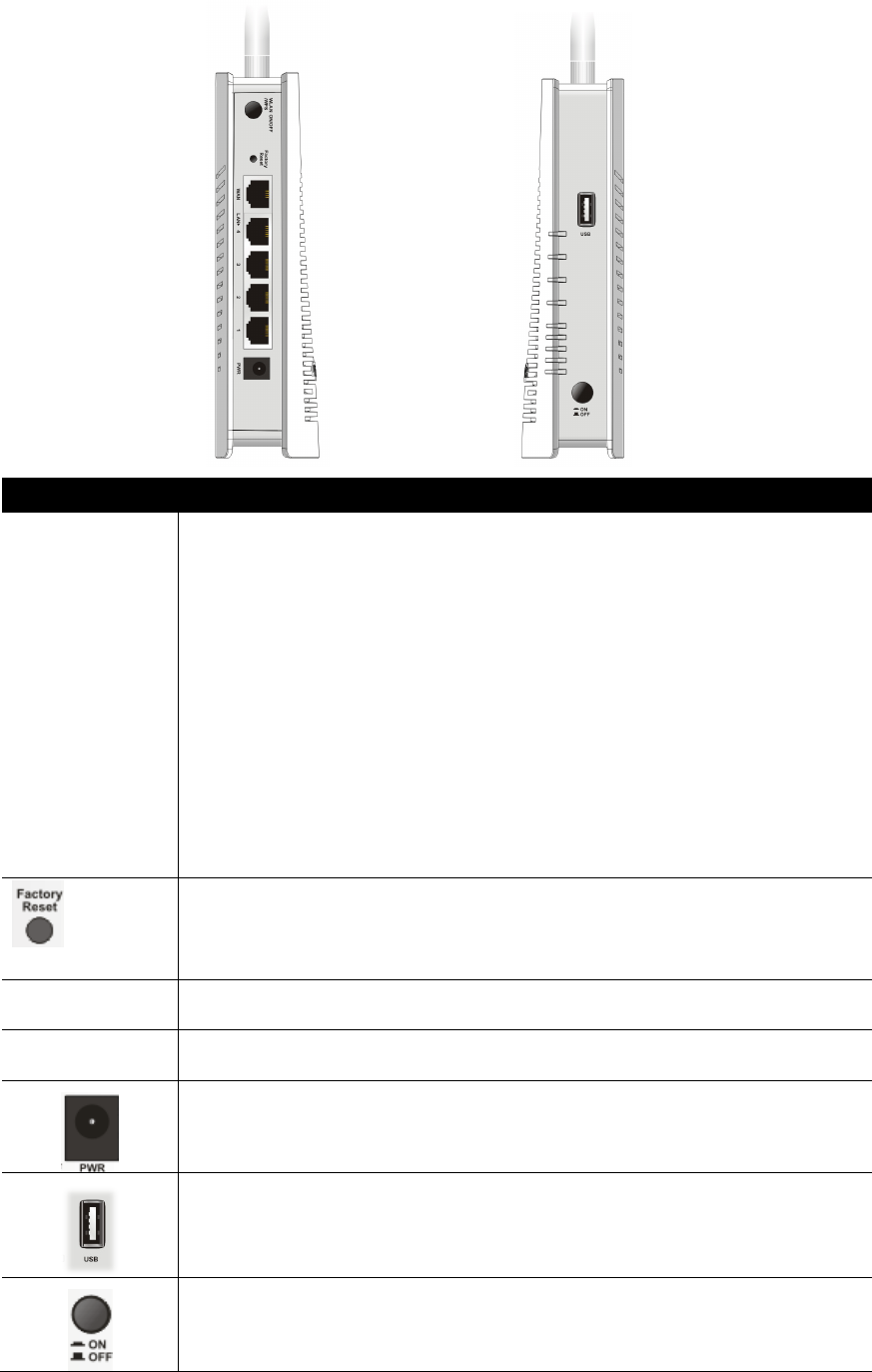
WLAN ON/OFF
WPS
WLAN On - Press the button and release it within 2 seconds.
When the wireless function is ready, the 2.4G/5G blue LED on front
panel will be on.
WLAN Off - Press the button and release it within 2 seconds to turn
off the WLAN function.
When the wireless function is not ready, 2.4G/5G blue LED on front
panel will be off.
WPS - When WPS function is enabled by web user interface, press
this button for more than 2 seconds.
The router will wait for any wireless client connecting to it through
WPS.
Factory Reset
Restore the default settings. Usage: Turn on the router. Press the
button and keep for more than 6 seconds. Then the router will
restart with the factory default configuration.
WAN
Connector for accessing the Internet.
LAN 1- 4
Connecters for local network devices (LAN).
PWR: Connecter for a power adapter.
Connecter for a USB device (for 3G USB Modem or printer or storage
disk).
ON/OFF: Power switch.
7
4
4.
.
H
Ha
ar
rd
dw
wa
ar
re
e
I
In
ns
st
ta
al
ll
la
at
ti
io
on
n
This section will guide you to install the router through hardware connection and
configure the router’s settings through web browser.
Before starting to configure the router (taking Vigor2122n for example), you
have to connect your devices correctly.
4
4.
.1
1
N
Ne
et
tw
wo
or
rk
k
C
Co
on
nn
ne
ec
ct
ti
io
on
n
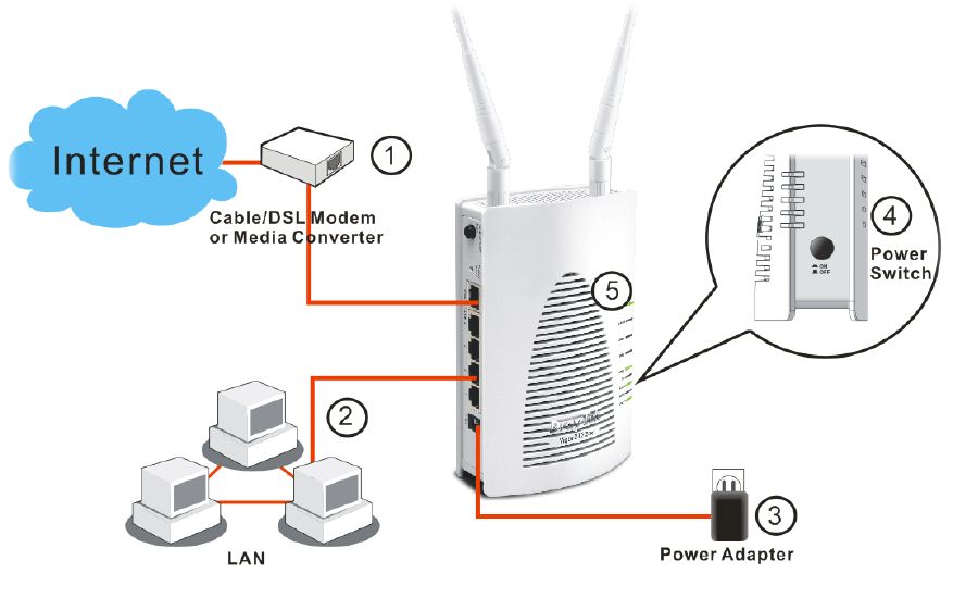
1. Connect the cable Modem/DSL Modem/Media Converter to the WAN port of
this router with Ethernet cable (RJ-45).
2. Connect one end of an Ethernet cable (RJ-45) to one of the LAN ports of the
router and the other end of the cable (RJ-45) into the Ethernet port on your
computer.
3. Connect one end of the power adapter to the router’s power port on the
rear panel, and the other side into a wall outlet.
4. Power on the device by pressing down the power switch on the rear panel.
5. The system starts to initiate. After completing the system test, the ACT LED
will light up and start blinking.
(For the detailed information of LED status, please refer to section 3.1~3.2.)
8
5
5.
.
S
So
of
ft
tw
wa
ar
re
e
C
Co
on
nf
fi
ig
gu
ur
ra
at
ti
io
on
n
To access Internet, please finish basic configuration after completing the
hardware installation.
The Quick Start Wizard is designed for you to easily set up your router for
Internet access. You can directly access the Quick Start Wizard via Web
Configurator.
1. Make sure your PC connects to the router correctly.
Note
You may either simply set up your computer to get IP dynamically
from the router or set up the IP address of the computer to be the
same subnet as the default IP address of Vigor router
192.168.1.1. For the detailed information, please refer to the
later section - Trouble Shooting of the guide.
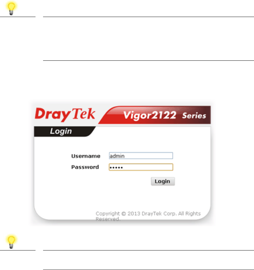
2. Open a web browser on your PC and type http://192.168.1.1. A pop-up
window will open to ask for username and password. Please type
“admin/admin” as the Username/Password and click Login.
Note
If you fail to access to the web configuration, please go to
“Trouble Shooting” for detecting and solving your problem.
9
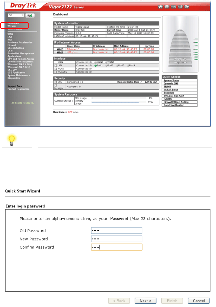
3. Now, the Main Screen will pop up. Click Wizards>>Quick Start Wizard.
Note
The home page will change slightly in accordance with the router
you have.
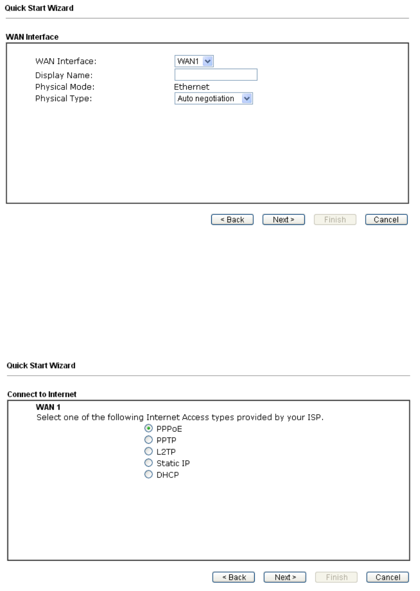
4. Enter the login password on the field of New Password and retype it on the
field of Confirm Password. Then click Next to continue.
10
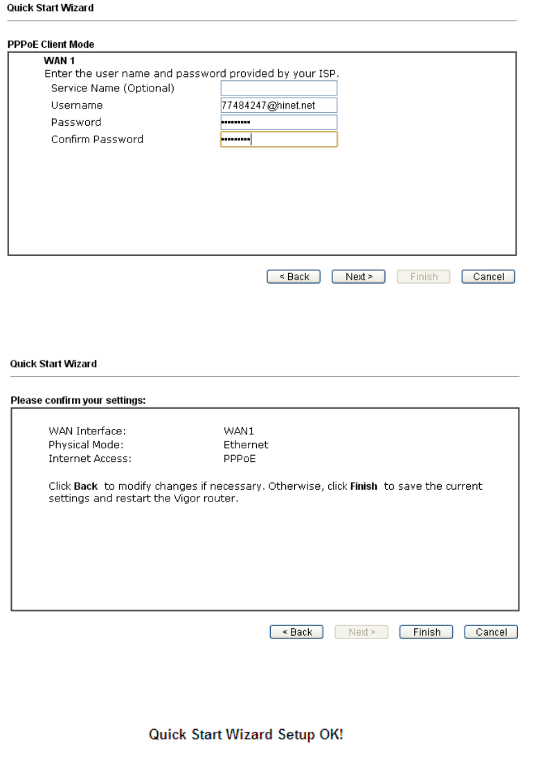
5. On the next page as shown below, please select the WAN interface that you
use. If Ethernet interface is used, please choose WAN1; if 3G USB modem is
used, please choose WAN2. Then click Next for next step.
WAN1 and WAN2 will bring up different configuration page. Refer to the
following for detailed information
Here we take WAN1 (Ethernet) as an example.
P
PP
PP
Po
oE
E
1. Choose WAN1 as the WAN Interface and click the Next button. The following
page will be open for you to specify Internet Access Type.
11
2. Click PPPoE as the Internet Access Type. Then click Next to get the
following page.
3. Manually enter the Username/Password provided by your ISP. Click Next for
viewing summary of such connection.
4. Click Finish. A page of Quick Start Wizard Setup OK!!! will appear. Then,
the system status of this protocol will be shown.
5. Now, you can enjoy surfing on the Internet.
12
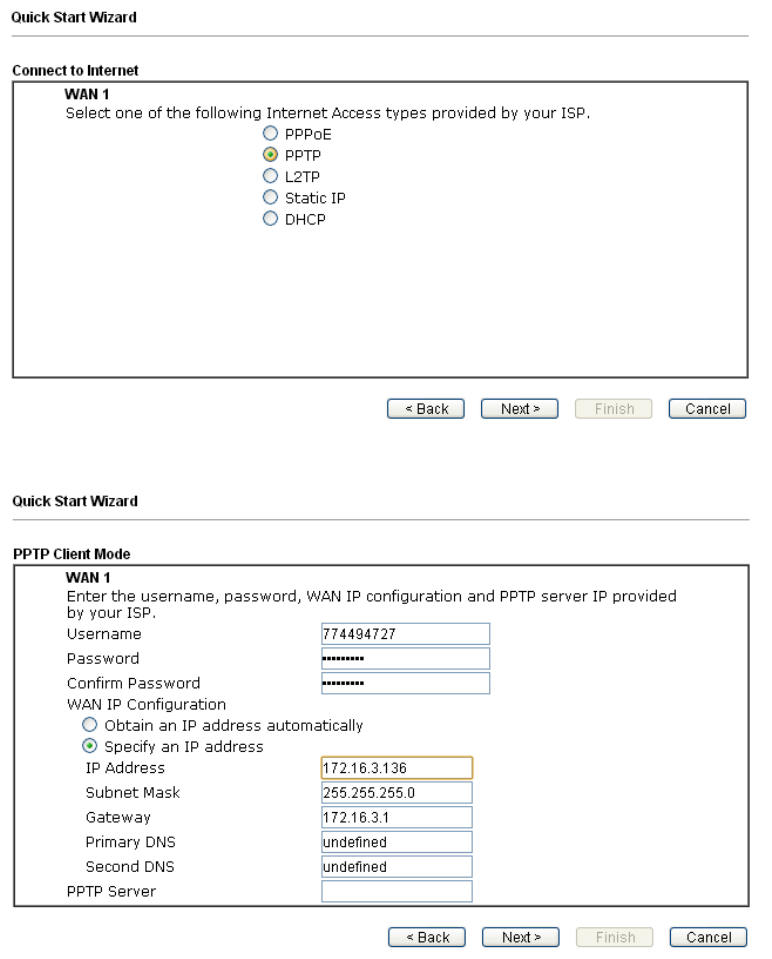
P
PP
PT
TP
P/
/L
L2
2T
TP
P
1. Choose WAN1 as the WAN Interface and click the Next button. The following
page will be open for you to specify Internet Access Type.
2. Click PPTP/L2TP as the Internet Access Type. Then click Next to continue.
13
3. Please type in the IP address/mask/gateway information originally provided
by your ISP. Then click Next for viewing summary of such connection.
4. Click Finish. A page of Quick Start Wizard Setup OK!!! will appear. Then,
the system status of this protocol will be shown.
5. Now, you can enjoy surfing on the Internet.
14
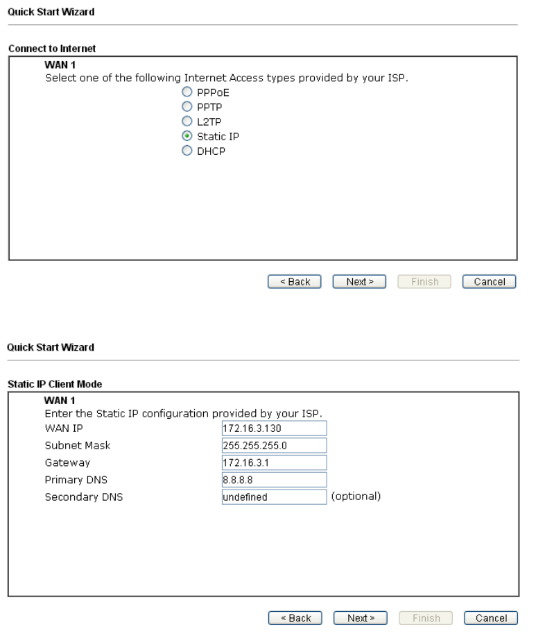
S
St
ta
at
ti
ic
c
I
IP
P
1. Choose WAN1 as the WAN Interface and click the Next button. The following
page will be open for you to specify Internet Access Type.
2. Click Static IP as the Internet Access type. Simply click Next to continue.
15
3. Please type in the IP address information originally provided by your ISP.
Then click Next for next step.
4. Click Finish. A page of Quick Start Wizard Setup OK!!! will appear. Then,
the system status of this protocol will be shown.
5. Now, you can enjoy surfing on the Internet.
16
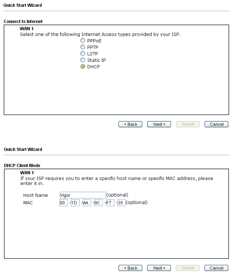
D
DH
HC
CP
P
1. Choose WAN1/WAN2 as WAN Interface and click the Next button. The
following page will be open for you to specify Internet Access Type.
2. Click DHCP as the Internet Access type. Simply click Next to continue.
17
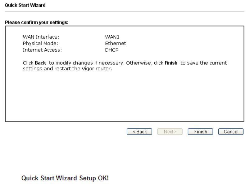
3. After finished the settings above, click Next for viewing summary of such
connection.
4. Click Finish. A page of Quick Start Wizard Setup OK!!! will appear. Then,
the system status of this protocol will be shown.
5. Now, you can enjoy surfing on the Internet.

18
6
6.
.
C
Cu
us
st
to
om
me
er
r
S
Se
er
rv
vi
ic
ce
e
If the router cannot work correctly after trying many efforts, please contact your
dealer/DrayTek for further help right away. For any questions, please feel free
to send e-mail to support@draytek.com.
B
Be
e
a
a
R
Re
eg
gi
is
st
te
er
re
ed
d
O
Ow
wn
ne
er
r
Web registration is preferred. You can register your Vigor router via
http://www.draytek.com.
F
Fi
ir
rm
mw
wa
ar
re
e
&
&
T
To
oo
ol
ls
s
U
Up
pd
da
at
te
es
s
Due to the continuous evolution of DrayTek technology, all routers will be
regularly upgraded. Please consult the DrayTek web site for more information on
newest firmware, tools and documents.
http://www.draytek.com