Draytek VAP810 Access Point User Manual Vigor2100V QIG
Draytek Corporation Access Point Vigor2100V QIG
Draytek >
User manual

V
Vi
ig
go
or
rA
AP
P
8
81
10
0
8
80
02
2.
.1
11
1n
n
A
Ac
cc
ce
es
ss
s
P
Po
oi
in
nt
t
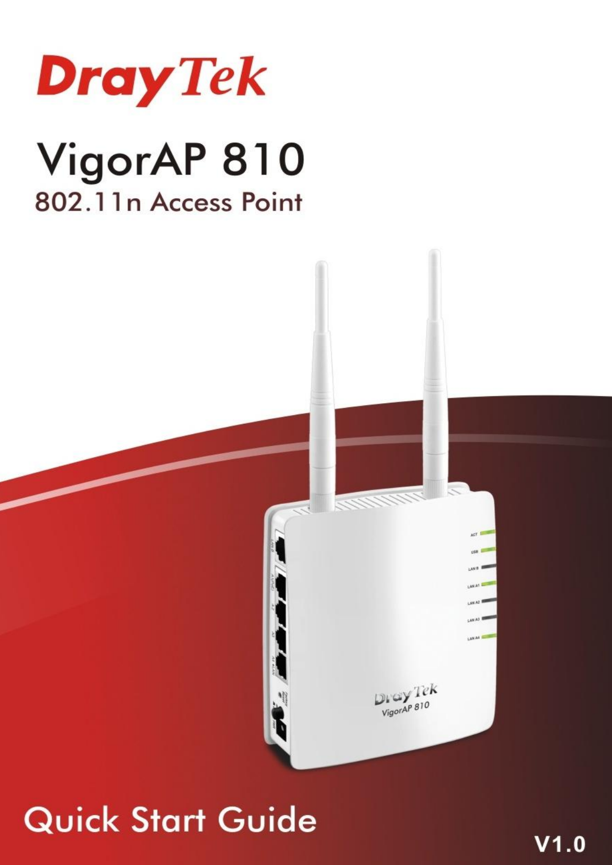
Quick Start Guide
Version: 1.0
(For future update, please visit DrayTek web site)
Date: Dec. 13, 2013
Warranty
We warrant to the original end user (purchaser) that the router will be free from any defects in workmanship or materials for a period of two (2)
years from the date of purchase from the dealer. Please keep your purchase receipt in a safe place as it serves as proof of date of purchase.
During the warranty period, and upon proof of purchase, should the product have indications of failure due to faulty workmanship and/or materials,
we will, at our discretion, repair or replace the defective products or components, without charge for either parts or labor, to whatever extent we
deem necessary tore-store the product to proper operating condition. Any replacement will consist of a new or re-manufactured functionally
equivalent product of equal value, and will be offered solely at our discretion. This warranty will not apply if the product is modified, misused,
tampered with, damaged by an act of God, or subjected to abnormal working conditions. The warranty does not cover the bundled or licensed
software of other vendors. Defects which do not significantly affect the usability of the product will not be covered by the warranty. We reserve the
right to revise the manual and online documentation and to make changes from time to time in the contents hereof without obligation to notify any
person of such revision or changes.
European Community Declarations
Manufacturer: DrayTek Corp.
Address: No. 26, Fu Shing Road, HuKou Township, HsinChu Industrial Park, Hsin-Chu, Taiwan 303
Product: VigorAP 810
DrayTek Corp. declares that VigorAP 810 is in compliance with the following essential requirements and other relevant provisions of R&TTE
Directive 1999/5/EEC.
The product conforms to the requirements of Electro-Magnetic Compatibility (EMC) Directive 2004/108/EC by complying with the requirements set
forth in EN55022/Class B and EN55024/Class B.
The product conforms to the requirements of Low Voltage (LVD) Directive 2006/95/EC by complying with the requirements set forth in EN60950-1.
This product is designed for 2.4GHz WLAN network throughout the EC region and Switzerland with restrictions in France.
Federal Communication Commission Interference Statement
This equipment has been tested and found to comply with the limits for a Class B digital device, pursuant to Part 15 of the FCC Rules. These limits
are designed to provide reasonable protection against harmful interference in a residential installation. This equipment generates, uses and can
radiate radio frequency energy and, if not installed and used in accordance with the instructions, may cause harmful interference to radio
communications. However, there is no guarantee that interference will not occur in a particular installation. If this equipment does cause harmful
interference to radio or television reception, which can be determined by turning the equipment off and on, the user is encouraged to try to correct
the interference by one of the following measures:
Reorient or relocate the receiving antenna.
Increase the separation between the equipment and receiver.
Connect the equipment into an outlet on a circuit different from that to which the receiver is connected.
Consult the dealer or an experienced radio/TV technician for help.
This device complies with Part 15 of the FCC Rules. Operation is subject to the following two conditions:
(1) This device may not cause harmful interference, and
(2) This device may accept any interference received, including interference that may cause undesired operation.
FCC Exposure notice
This equipment complies with RFCC radiation exposure limits set forth for an uncontrolled environment.
This equipment should be installed and operated with minimum 20cm between the radiator and your body.
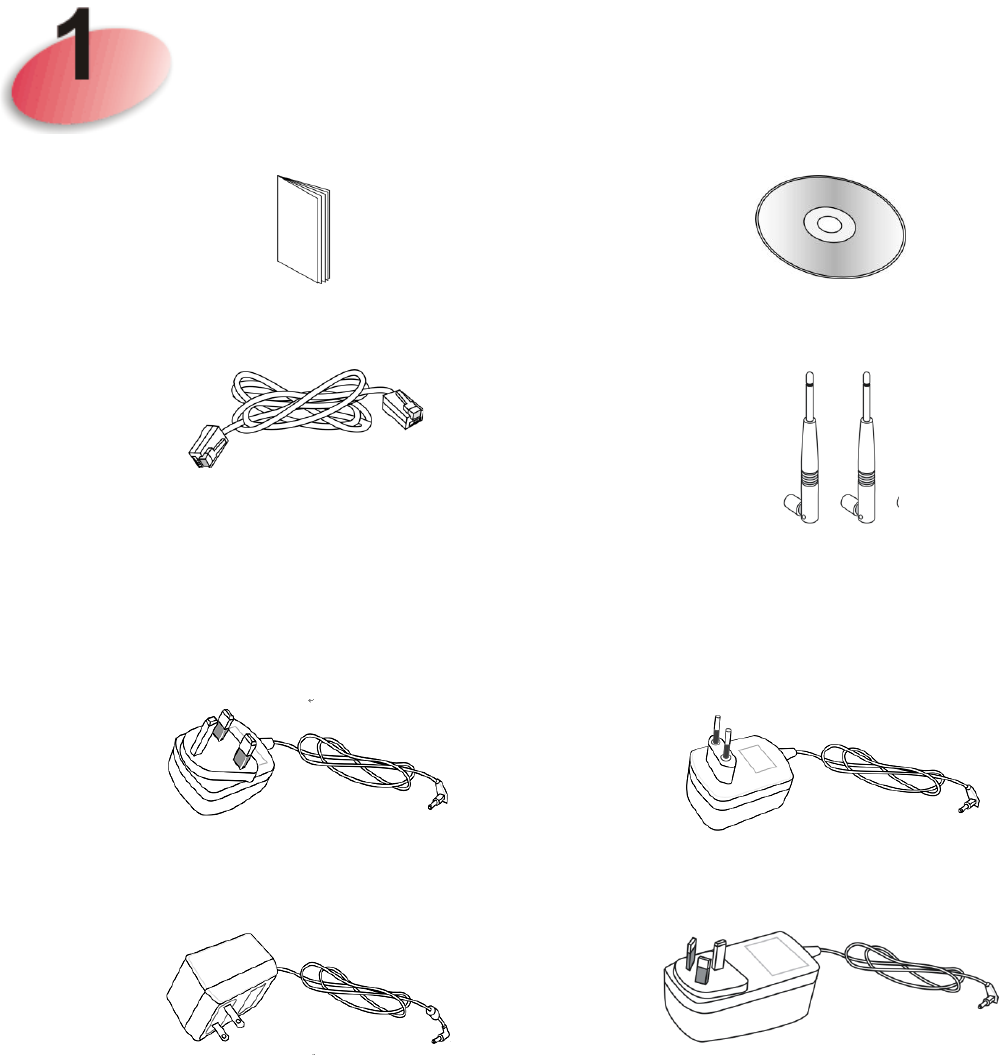
Package Content
Quick Start Guide
CD
RJ-45 Cable (Ethernet)
Antenna
The type of the power adapter depends on the country that the router will be
installed:
UK-type power adapter
EU-type power adapter
USA/Taiwan-type power adapter
AU/NZ-type Power Adapter
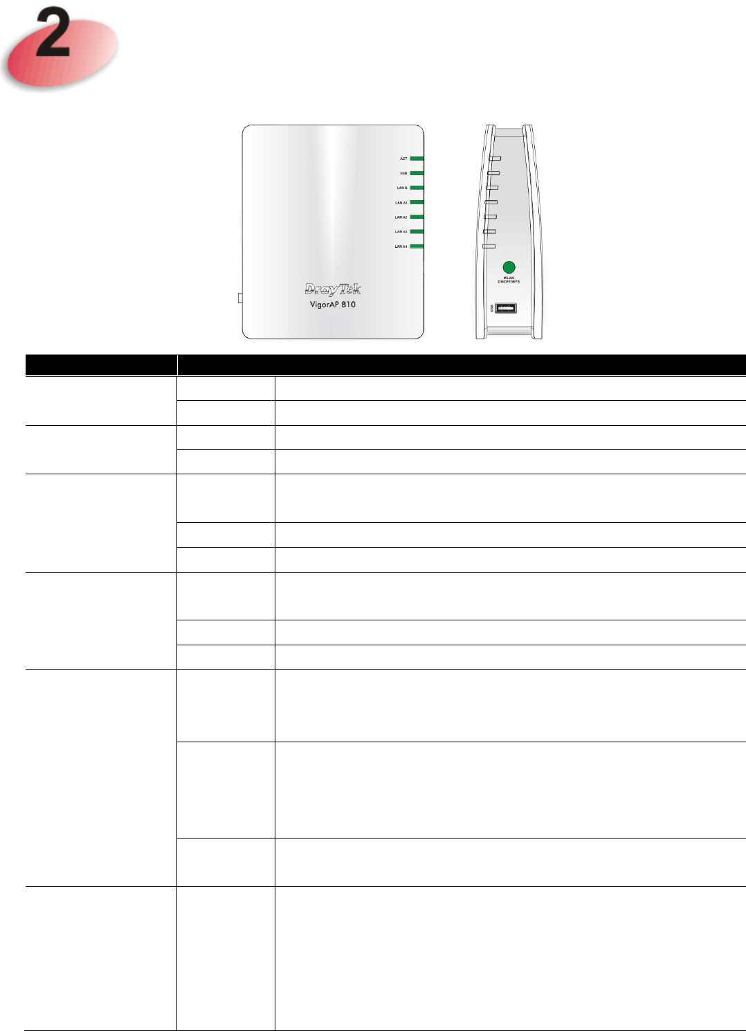
Descriptions of Components
LED
Status
Explanation
ACT
Off
The system is not ready or is failed.
Blinking
The system is ready and can work normally.
USB
On
A USB device is connected and active.
Blinking
The data is transmitting.
LAN B
On
A normal connection is through its corresponding
port.
Off
LAN is disconnected.
Blinking
Data is transmitting (sending/receiving).
LAN A1 - A4
On
A normal connection is through its corresponding
port.
Off
LAN is disconnected.
Blinking
Data is transmitting (sending/receiving).
WLAN
(Green LED) on
WLAN button
On
Press the button and release it within 2 seconds.
When the wireless function is ready, the green LED
will be on.
Off
Press the button and release it within 2 seconds to
turn off the WLAN function.
When the wireless function is not ready, the LED
will be off.
Blinking
(Green)
Data is transmitting (sending/receiving).
WPS
(Orange LED)
on WLAN
button
Blinking
(
Orange
)
When WPS function is enabled by web user
interface, press this button for more than 2 seconds to
wait for client’s device making
network connection
through WPS.
When the orange LED blinks with 1 second cycle for
2 minutes, it means that the AP is waiting for wireless
client to connect
with it.
USB
Connector for a printer.
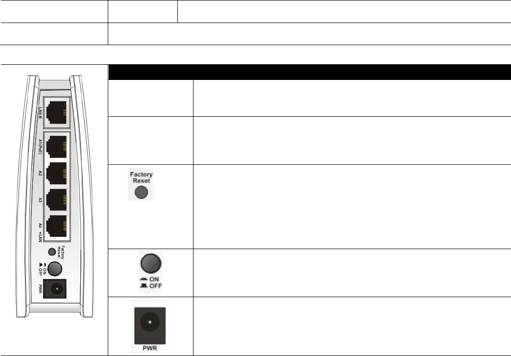
Interface
Description
LAN B
Connecter for xDSL / Cable modem or router.
LAN A1
(PoE) - A4
Connecter for xDSL / Cable modem or router.
Restore the default settings. Usage: Turn on the
router. Press the button and keep for more than 10
seconds. Then the router will restart with the
factory default configuration.
ON/OFF: Power switch.
PWR: Connecter for a power adapter.
Installing Your Router
This section will guide you to install the AP through hardware connection
and configure the settings through web browser.
Before starting to configure the router, you have to connect your devices
correctly.
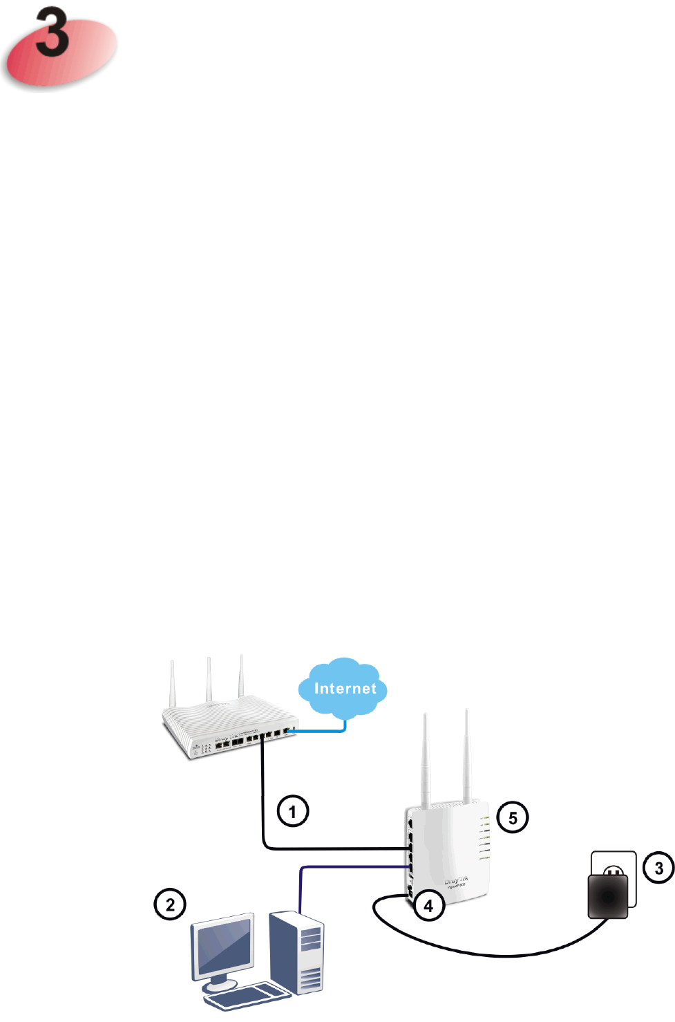
1. Connect VigorAP 810 to ADSL modem, router, or switch/hub in your
network through the LAN A port of the access point by Ethernet cable.
Note: You can also connect VigorAP 810 to a Vigor router via wireless
connection. For detailed information, refer to VigorAP 810 User’s
Guide.
2. Connect a computer to other available LAN A port. Make sure the
subnet IP address of the PC is the same as VigorAP 810 management IP,
e.g., 192.168.1.X.
3. Connect the A/C power adapter to the wall socket, and then connect it to
the PWR connector of the access point.
4. Power on VigorAP 810.
5. Check all LEDs on the front panel. ACT LED should be steadily on,
LAN LEDs should be on if the access point is correctly connected to the
ADSL modem, router or switch/hub.
Configuring Web Pages
The Operation Mode is designed for you to easily set up your router for Internet
access.
Note: Such VigorAP is treated as DHCP client. So, if it is connected as the
figure on the previous page, the default IP will be changed and assigned by
the DHCP server of Vigor router.
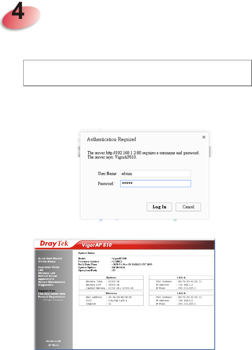
1. Make sure your PC connects to the router correctly.
2. Open a web browser on your PC and type http://192.168.1.2 (for stand-alone
installation). A pop-up window will open to ask for username and password.
Pease type “admin/admin” on Username/Password and click Login.
3. The Main Screen will pop up. Click Quick Start Wizard.
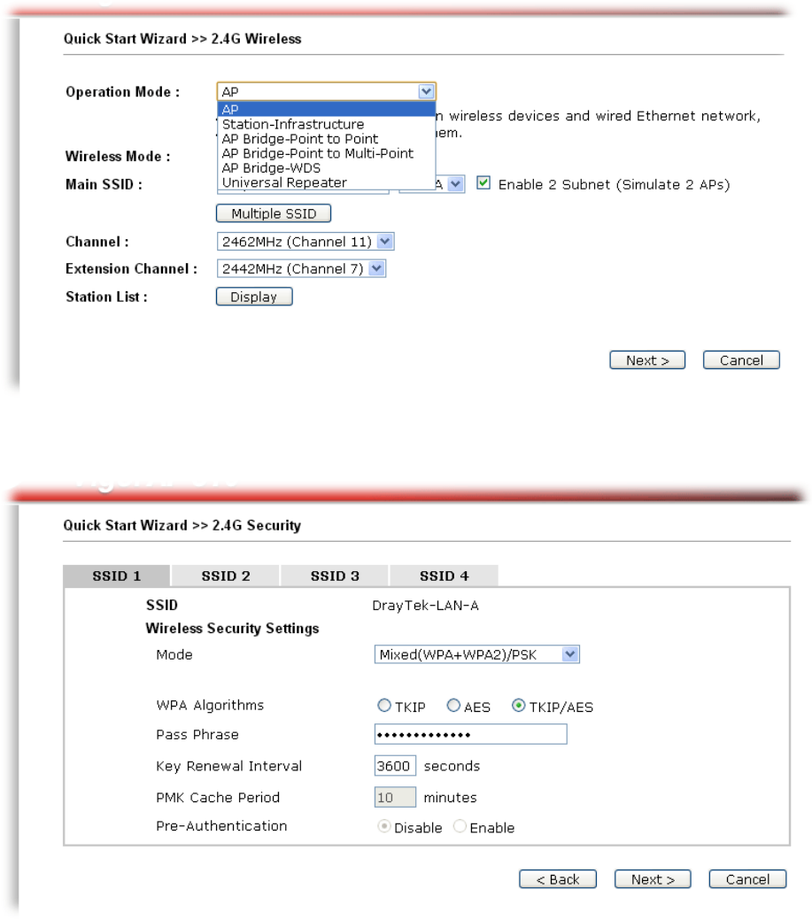
4. The first page is set for 2.4G wireless connection. There are several operation
modes for you to choose. Simply click any one of modes. In this example,
choose AP and click Next.
5. For the SSID configuration, choose the mode you want and type related
information for client authentication. Then, click Next.
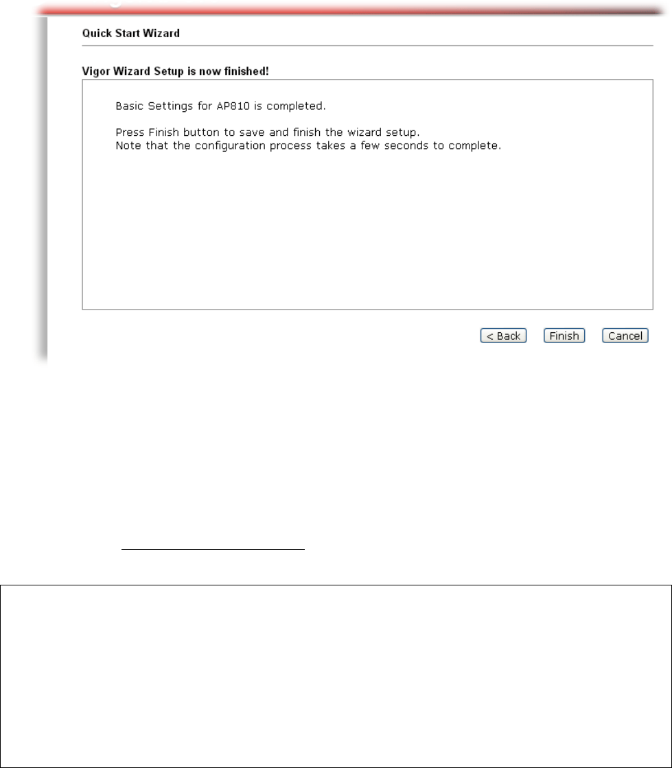
6. In the next page, click Finish. The system will make a connection
automatically.
Open Online Status to see the result of network connection. Now, VigorAP 810
is ready for any station to connect for accessing Internet.
Contacting Your Dealer
If the router still cannot work correctly after trying many efforts, please contact
your dealer for further help right away. For any questions, please feel free to
send e-mail to support@draytek.com.
Safety
Instructions
Read the installation guide thoroughly before you set up the router.
The router is a complicated electronic unit that may be repaired only be authorized and
qualified personnel. Do not try to open or repair the router yourself.
Do not place the router in a damp or humid place, e.g. a bathroom.
The router should be used in a sheltered area, within a temperature range of +5 to +40 Celsius.
Do not expose the router to direct sunlight or other heat sources. The housing and electronic
components may be damaged by direct sunlight or heat sources.
Do not deploy the cable for LAN connection outdoor to prevent electronic shock hazards.
Keep the package out of reach of children.
When you want to dispose of the router, please follow local regulations on conservation of the
environment.