Dremel 1671 Owners Manual ManualsLib Makes It Easy To Find Manuals Online!
2014-12-12
: Dremel Dremel-1671-Owners-Manual-119740 dremel-1671-owners-manual-119740 dremel pdf
Open the PDF directly: View PDF ![]() .
.
Page Count: 16

DR
M
L:
SCROL
a er s manual
WARNING
For your own
sa
fety
read your
Owner s Manual
before operating
your
MODEL 1671 T
PE
2 SC
Dremel
Scroll Saw a
ss
embly • operation • safet instruc ions
DREM
L:
49
15
- 21 st
Street
IR
acine
.
Wisco
nsin 53406, U.S.A.
For
m
No
. 5296678 4/
91
PAINTE
D
IN
U.S
A.

For Your Safety
...
•
READ
ALL
INSTR
UC
TIONS Failure
to
follow the safety rules listed
below
and other
AWARNING basic safety pre
ca
uti
on
s may result
In
serious personal injury.
W
ork
Area
• KEEP W
ORK
AREAS CLEAN. Cluttered areas and
benches invite accidents.
• M A
KE
WORKSHOP
CH I LD·PROOF-
wlth
padlocks,
aster switches. or by removing starter keys.
Perso na I Safe
ty
• STAY
AL
ER
T.
Watch what
you
a
re
doin
g.
Use
common sense.
Do
not operate tool when you are
ti red.
• KEEP GUARDS
IN
PLACE,
in
working
order, and
in
proper adjustment and alignment.
•
DON'T
OVERREACH. Keep proper footing and
balance at all Imes.
•
DISCONNECT
TOOLS.
When
not in use; before
servicing; when c langmg blades. bits, cutters,
etc.
•
REMOVE
ADJUSTIN
G KEYS
AND
WRENC
HES.
For
m habit
of
chee to
see
that keys and adjusting
wrench
es
are removed
~rom
tool before turning it on.
• N EVER STA
ND
ON TOOL.
Se
riousinjurycouldoccur
If the tool
IS
tipped
or
If the cutting tool
is
acci-
dent
ally contacted.
•
AVOID
ACCI DENTAL S
TA
RTING. Don't carry
plugg
-n
001
'h
finger on switch.
Be
sure
s
ch
IS
OFF
en plugg
ed
Tn.
• USE
RECOMMEND
E
DACC
ESSORIE
S.
Consultthe
owner's
manual for r
ec
om
mended accessor
ies.
Follow [he instructions that accompany the acc
es
-
sOries. The use
of
improper accessories may
cause hazards.
• DRESS PROPERL
Y.
Do
not
we
ar
loo
se
clothing or
j
ew
elry. Th
ey
can
be
c
au
ght in moving parts. Rubber
gloves and non-skid footwear are
re
commended
whe
n
working
outdoors. Wear protective hair
covering to contain long hair.
•
ALWA
YS USE SA FETY GLASSES. Also use face or
dust mask
if
cutting operation is dusty. Everyday
eyeglasses only have impact resistant l
en
se
s;
they are
not
safety glasses.
All repairs. electrical or mechanical.
AWARNING s
ho
uld be attempted
only
by trained
repairmen. Contact the nearest Dr mel Service Center,
or
AuthOrized Dremel Service Station or other com-
petent repair service. U
se
only
Dremel replacement
parts; any other may create a hazard.
•
CHECK
DAMAGED
PARTS. Before further use
of
e
001.
a guard or other part that is damaged should
care ully checked to determine that it
will
operate
proper and perform its
int
ended function. Check f
or
alg
e
of
moving parts, binding of
mo
ving parts,
ea
ge
0 parts, mounting, and any other conditions
- a ec s operation. Aguard or other part that
ed s
00
d be properly repai r
ed
or replaced.
SWitches replace
d.
Do not
lj
se tool if
urn
It
on or off.
Tool
Use
CE TOOL. It
will
do
th
e job
bett
er and
_
or
which
it was designed.
TOOL
Don 't force sma
ll
tool
or
Job
of
a heavy-dUty tool. Don't
OOfDC>se
no
Intended-
for
exa
mple; don't
c mg tree limbs or l
og
s.
• SECURE se lamps or a vise to hold work.
It's
safe
~
hand and it fm
es
bo
th
hands
OFFEED. Feedworkm
oabl
a
deorcu
tter
against
tn
of
ro allan
of
the blade or cutter
only.
• NEVER
LEAVE
TOOL
RUNNING
UNATTENDED.
Turn
pOVlier
• lea e too until it comes
to
a
co
mplete s OP
• DO
NOT
ALTER 0
preciSion
bLJ
s
pe
cified
IS
condition.
• AVOID GASEOUS
tools in gaseo s
the
se
tools
no
ig
nit
e fumes.
• M
AINTAIN
TOOLS
WITH
CARE. Keep tools sharp
an
d clean for
be
e and safer performance. Follow
instru tions for ng and changing accessories.
Inspect tool cords per odically and jf damaged, have
re
paired
by
aut
eel
Service
facility. I nspect exten-
si
on cords per
00
cally and replace
if
damaged. Keep
ha
ndles dry. clean and free
from
oil and grease.
Before connecting the tool to B
AWARNING power source (receptacle, outlet.
etc.), be sure voltage supplied is the same
as
tha t
specified on the nameplate
of
the tool. A
power
sou rce
With voltage greater than that specified
for
the tool can
result in SERIOUS INJURY to the user,
as
well
as
damage to the tool.
If
in doubt.
DO
NOT PLUG IN THE
TOOL.
USing a
power
source
with
voltage less than
the nameplate rating
is
harmf
ul to the motor.
"SAVE THESE I
NS
TRUCTIONS"
Page
2

Tool Safety Rules
• For you r w n safety,
do
not
attempt
AWARNING
to operate y
our
scroll saw u
nlll
it is
completely assembled and ins
ta
ll
ed
accordIng to the
instr
uct
ions
..
. and until you read and understand
the
following:
• GENERAL SAF
ETY
RULES
....
.
..
.......
See
Pa
ge
2
• T
OO
L RULES
................
.
..
.....
..
See
Page
3
• GEm NG
TO
KNOW YOUR S
AW
...
.
....
See
Page
5
• OPERATIONS
........
..
..
.. ..
..
See Page 0
• AD
JU
ST
MENTS
.
......
..
...
....
. See
Pa
ges 6 7 8
• M
AIN
TENANCE
............
..
. .
..
.
..
See
Pag
Stabi I
ity
of
Saw
• Your scroll saw must be bolted securely to a stand 0
workbench. In addition, if there is any tendency
for'
e
scroll s
aw
t tip over or move
during
certain operat ons
such
as
cut
ting long, heavy boards. bolt your scro
ll
Sil
stand or
workbenc
h to the floor.
L
ocation
• This scroll
sa
w
IS
intended for Indoor use only.
Protec
tion
: Eyes,
Hands, Face, Ears, Body
• Wear safety
go
ggl
es
and
a face shield if operation is
dusty. Wear ear plugs or
mu
ff
s during extended
periods
of
op
eration. Do
not
we
ar gloves .
..
roll long
sleeves above the elbow.
• Do
not
cut
p,
ec
es
of
material too
sm
all to hold by
hand. HINT:
When
making a very small cutout.
always secure the workpiece to a scrap piece of
plywood
WI
h
doub
le-faced tape.
Th
is w
ay,
the
wor
k is
supported and your fingers are away from the blade.
•
AVOid
awkward
hand positions
where
a sudden slip
could cause a hand to move into the blade.
• Never turn
your
scroll saw on before clearing the table
of all objects (tools, scraps of wood. etc.) except for the
workpiece and related feed or support devices for the
operation planned.
• ALWAYS adjust the
drop
foot and b
la
de guard to just
clear the
workpiece
to
protect the
op
erator. keep blade
breakage
to
a mi
nimum
and provide
maximum
support
for
blade.
• Always
adjust
blade
te
nsion correctly.
•
Make
sure blade teeth run
downward
toward
table.
Page 3
:ike su
re
it
IS
• Hold the
work
fl
Only
feed the matenal fast e cut.
Keep fingers away fro
• Do not feed the ma e
• Use caution w hen
cutting
(
In
cross sec
ti
on
-It co Id p
cut
is complet d. A ple .. e
of
must
lay flat on the table and not
mIle being
Cll
t.
• Use caution when
cutting
oft
round materta
a
Ne
l rods or
tub
ing. They have a
te
ndenc
5 -
de
being cut. c
au
sing the bl
ad
e to bite
• e
esaw
OFF
, make sur
_
00
r leave the scr " saw runnmg unatten
ed
. T
rn
the saw h
as
come
toa
camp
ete
and th
en
remove plug fr
om
power
suppl
efore
tile
work
area.
•
no
perform layout. assembly or setup work on
lhe
Ie
the cutti ng tool IS operating.
off
and remove plug from
power
supply
outlet
5tal mg or removing
an
accessory attachment
•
• av,
_ Iy
par! of this
sc
roll saw
be
missing. bend or
or any e
le
ctric
al
compo
nent fatl to
shut
off
powe
r
switch
and remove
r supply outl
et.
.
Replace
d
am
aged
, missi
ng.
IS before
re
suming
operation.
Think
Safety
n of operator
comm
on sense and
sc
ro
ll s
aw
is
in
operation.
•
AWARNING
o
allow
familiarity (g
ai
ned
fr
om
uent
use
of
your scroll saw)
to
I a s remember
ha
a care-
become carefe s _
less fraction
0'
a
~p.(~nid
mJU ry.
WEA
The
operation
of
any
power
tool can result
in
foreign
objects being
thrown
into
the
eyes. w hich can result in
seve
re
eye damage.
Always
wear safety glasses or eye
shields before commencing
power
tool
oper
ation.
We
recom
men
d
Wide
Vision
Safety
Mask
for
use
over
spectacles or standard safety glasses.

•
Grounding Instructions
Grounded Too
ls
With
Three-Prong Plugs
I mproper grounding ca s oc
AWARNING or electroc e
Grounding of this tool is necessa
tect you fro m electric shoc a
is equ ipped
with
an appro '
!h,·
,
.:H>-JVO,ftn
three-prong ground n9-
grou nding-type rece
'3_
'==
pro 9 from the ree pr e
green (or green and e C a
elOf
In
the cord s the
grounding
wire
e e onnect
he
green (or green and
yellow) wire
to
a e termmal. Your unIt
is
for use
on
less than 1
50
volts
an
d it has plug
that
looks like
Fig. "A".
FIG. A FIG. C A
,'
ap"
"
FIG . B
~
CU!
err
G
ruundlnQ
G·
oun
dlrlll
Cover 0' Grou
nded
Means
-
P·onq
QUI
II't
Bo)(
An ada
pt
.r,
Fi
g.
8 " and '
C"
is
availa
bl
e for connecting
Fig A plugs to
two
-prong r
ec
eptacl
es.
The green
colored
ngld
ear. ug etc
.,
e tending from the adapter
must
be connected 0 a permanent grou nd such
as
a
properl
gra
ded
au
Ie
box
o ernel
OTE The grounding adapter. Fig. "C"
is
prohibit
ed
in
C=
a b Canadian Electrical Code-Part 1. Therefore
ons for
Its
u
se
are not applicable
In
Canada.
Extension Cords
se
of
damaged cords
ca
n shock,
burn
Dr
el
ectrocute.
o
worn
cords immediately. The
c size
to
u e, depending on cord
'e amperage rating
of
tool.
If
in
t:3Vler gauge. An undersized cord
hne voltag
e,
resulting in loss
of
. NOTE: The smaller the
ga
uge
e cord.
ension cor s w ith three-ho
le
he tool plug and ha
ve
three-
pugs.
T
hr
ee-wi
re
ext
en
sion
A
eCOlmn:lelxl
um
Gauge
for
Cord
Extensions
e
Electri
c Tools
9
Chart
A.W
.G.
-
-----
--1
Cord
Length
in
Feet
50
100
'50
, 6
14
14 12
4
12
"4
12
Not
Recommended
Your
Dremel product
IS
'/arranted against defective
ma
terial
Of
!"
U HORIZEO REPAIRS OR
workmanst1ip f
or
a period of ooe
ye
ar f
rom
date of purchase, In
Ih~
J}tIIm:::O\~
TTACHMENTS OR
OT
HE
R
even! of a
fa
ilur of a produCl
to
conform
to
this written
WaIT
an
LEMS
WIT
H
MA
TE
R
IAL
OR
please take
th
e following actioo:
BEe
BY
TH
IS WARRAN
TY,
•
1, DO NOT return your produ
ct
to
the place of purchase, e.' person IS authorized to ive any
Dremal inspection shows that the
2. Carefully package the product by itself. with no other item
s,
PI' S
With
mate
ri
al or workmanship
retu
rn
it
freight prepaid.
al
ong with: arran y Dremel wi
ll
repair or rep
la
ce the
A.
A copy of your dated proof of purc
ha
se (please
kee
p a
~
elum product prepai
d.
Repal
rs
made
for yourself).
€a
abuse.
or repair for product outside the
'" ca
be
made. will be charged
at
re
gular
B A written statement about
th
e nature of the problem.
C
Your
nam
e.
address and phone number
to:
AE
E...
ES
NO OTH
ER
WARRA
NTY
OF
ANY
KIND
TEVER.
EXPRESSED
OR
IM
PLIED. A
ND
ALL I
MPl
iED
UNITED STATES
"'
... "-"'
..
",,'
ES
OF ERCHANTABI
LITY
AND F
ITN
ESS
FOR A
PAR
-
Dremel
Service Cen
ter
Dremel Service
Cente1'
C PURPOSE WHICH EXCEED THE ABO
VE
MENTIONED
4915
Twenty-F
irs
t
St
r
eet
OR
4631
E.
Su
nny
[)t
BUGATlON
AR
E HEREBY DISCLAIMED
BY
D
RE
MEL
AND
Racine. Wlsconsin
53406
Palm
Spnngs,
CA
2264 EXCLUDED FROM T
HI
LI
MI
TE
D
WA
RR
ANTY
.
EASTERN CANADA WESTE
RN
CANADA
ThIs arranty gives you specific legal rig
ht
s and you may also have
Giles
Tool
Agency otem Tools olher rights
wt1
ich vary from state to state. The obligation of the
6520 Lawrence a
...
.
east,
OR
3851 Main
51.
warrantor
is
solely to repair or replace!h product. The warrantor Is
Scarborough,
Onl.
Va
ncou
...
er,
ac
. not liable torany inCidental
or
consequenti
al
damages due to any such
Canada M1C 4A7 Canada
V5V
3P1
alleged defect
So
me states do not allow the excl sicn or limltalionsof
We recommend that the package be insured against lossordamage
in
incidental or
r.
onseQuenlial damages, so the above Iimita1ions
or
transit,
for
which we cannot be
res
ponsi
Ie.
exclu
si
on may not apply to you.
This warranty applies only
to
the original registered purchaser.
For
p
ri
ces and warranty fulfillment
in
the continental United Sates,
DAMAGE TO THE P
ROD
UCT
RES
ULTI
NG
F OM TAMPERING, cootac! your local Dremel dislnbutor.
Pa
ge4
_ __
\
~~~~~
~~
TABLE INSERT
POSITIONED
FOR
PLAIN END BLADES
DEGR
EE
SCALE
TAB
LE
INS
ERT
ON/
OFf
SWITCH
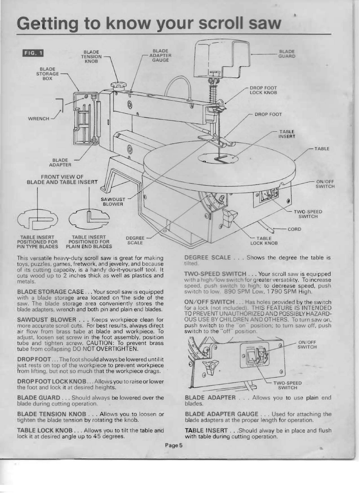
Getting to know your scr
DEGREE SCALE
I e
liM'
BLADE
STORAGE \
BOX
-:1
WRENCH~
BLADE
ADAPTER
FRONT
VIEW
OF
BLADE
AND
TABLE INSERT
Th
is
versatile heavy-duty scroll saw
is
great for making
toys, puzzles,
ga
m
es
, fretw
or
k,
and
Je
welry,
an
d because
of its cutting capa
ci
ty, is a han y do-it-yourself too
l.
It
cuts
wood
up
to
2 inches thick
as
well
as
plastics and
metals.
BLADE STORAGE CASE
..
. Your scroll
saw
is
equipped
with
a blade storage
area
located on he side of the
saw. The blade stor
ag
e ar
ea
conv
en
ie
ntly
st
or
es
the
blade adapters, wrench
and
both pin
and
plain e
nd
b
lades
.
SAWDUST BLOWER
...
Keeps workpiece clean for
more accurate scroll cu
s.
Fo
r best resu lt
s,
always direct
air
flow
from brass tube at blade and
wor
kpiece.
To
adjust. loosen set screw in the foot assembly, position
tube and tighten screw.
CA
UTI ON:
To
prevent brass
tu be from collapsmg
DO
NOT OVERTIGHTEN.
DROP FOOT,. The foot should always be lowered until it
just rests on
top
of
the
work
pi
ec
e
to
prevent workpiece
from lifting,
but
not so much
th
at the
wo
rkpiece drags.
DROP FOOT LOCK KNOB .. A
ll
o
ws
you to
ra
ise or lower
the foot and lock it at desired heights.
BLADE GUARD
...
Should always
be
l
ow
ered over the
blade during cutting operation
BLADE TENSION KNOB .
..
All
ows
you to loosen or
tighten the blade tension by rotating the kno
b.
TABLE LOCK KNOB .
..
All
ows
you to
tilt
the table and
lock it at desired angle
up
to
45
degrees.
TABLE INSERT
POSITIONED
FOR
PIN
lYPE
BLADES
Page5
Fr
-
'~
1
~
Shows the degree the table
is
TCH . . . Your scroll saw
is
equipp
ed
ch or
gr
eater versatility. To incr
eas
e
a
1'1Igh
, t decrea e speed, push
SLow
, 17
90
SPM
Hi
gh.
ON/OFF
SWITCH . as holes pr
OV
ided by he SWitch
for a lock (not
dud
'HIS
FEA
T
URE
IS
INTENDED
TOPREVENTUNAU O IZEOAN OPOSSIB LY HAZARD-
OUS USE
BY
CHILD E D OT
HERS.
To
turn saw on,
pu
sh
swi
tch
to
the 0
po
_It on; a turn
saw
off, push
switch to t
he
"
off
.
ON/
OFF
SWITCH
BLADE ADAPTER . . .
Allows
you to us plain end
blades.
BLADE ADAPTER
GAUGE.
, , Used for attaching the
bl
ad
e
ad
apters at the proper length for operation.
TABLE INSERT .
..
Should alway be in place and flush
with
table during cutting operation
I
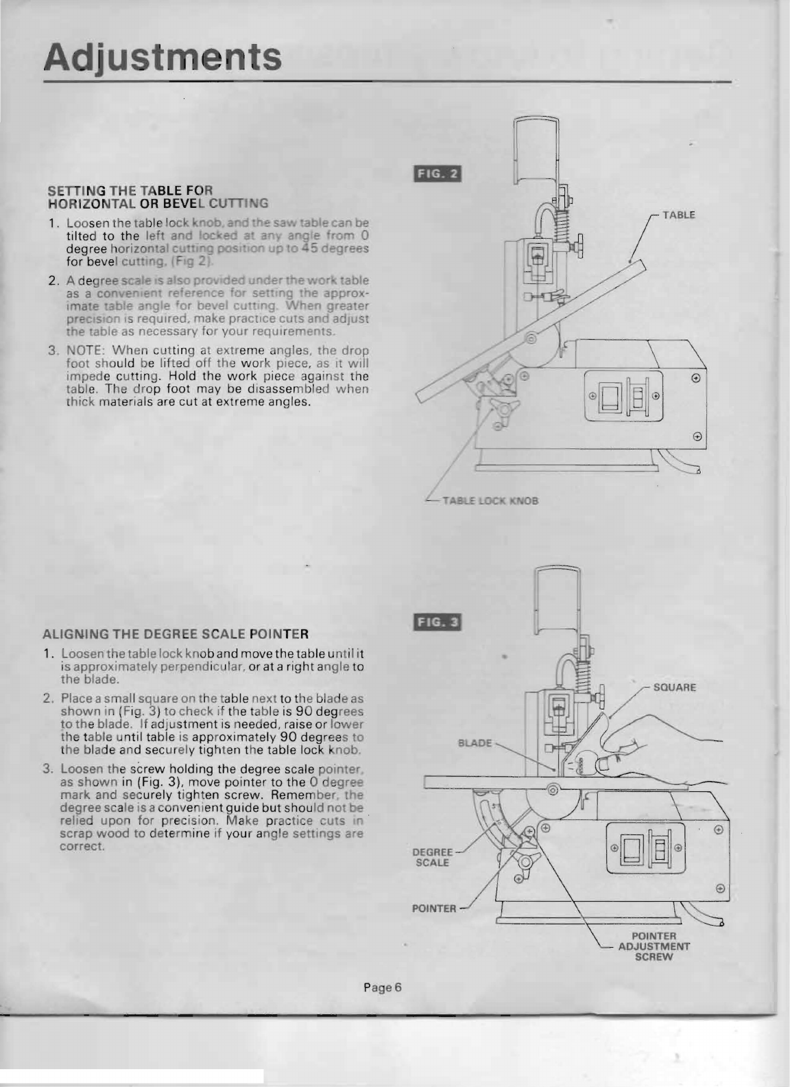
Adj stments
r
SETII
NG THE TABLE
FO
R
HORIZONTAL
OR
BEVEL
cun
G
1.
Loo
sen the tabl l
ad
tilte
d
to
the
left
an
degree h
orizorta
-
for
bevel CU " 9 F
2. A degree
~-
..
as
a c'"
::
Ima
epa
9 e r be al c • og 0 grea "'r
pre
ISI-
IS
required, make practice c
ts
a d adJus'
e 'able
as
necessary f r
your
requlrerne
ts
3. OTE:
When
cutt
ing at
extr
eme ngle
s.
he drop
foot
should be lifted
off
the
wo
rk
piece,
as
It
will
imped
e cut
tin
g. Hold the
work
piece
ag
ai
nst
the
table. The
dr
op
foot
may be disassembled
when
t
hick
materi als are
cut
at
extreme
angles.
ALIGNING THE DEGR EE SCALE POINTER
1. Loosen the table
lock
knob a nd move
the
ta ble u
nt
i I it
is
approximately
perpend icular, or at a
right
angle
to
the
blade.
2. Place asmall square
on
the table
next
to
the bla e
as
shown
in (Fig. 3)
to
check if the table is 90 degrees
to
th
e blade.
If
adju
st
me
nt
is needed, raise
or
lower
the table u
ntil
table is appr
oximately
90
deg
rees
"0
the blade and sec
ur
el
y
tig
hten the table
lock
nob.
3. Loosen the s
crew
holding
the degree scale
pomte
r
as
shown
in (Fig. 3), move
pointer
to
the
0
degrfO>
e
mark
and securely tighten
screw
. Remem
ber
t e
degree
scale is a convenient gu ide
but
shou
ld
no
be
relied
upon
for
precision, Make p
ra
ctice
uts
.
scrap
wood
to
dete
rm
ine
if
your a
ng
le
settings
are
correct.
ADJUSTMENT
SCREW
POINTER
POINTER
P
age6

BLADE
POSITIONED
FOR
FRONT
CUmNG
TABLE TILTED
FOR PICTURE
CLARITY
BLADE
POSITIONED
F
OR
SIDE
CU
TII
NG
UP
PE
R INNER
BLADE HOLDER
Removi 9 and installin blades
Page 7
BLADES
Yo
u r new scroll
sa
w
ac
cept
s 5 inch pin
type
blades. Your
saw i al o
equippe
dw
it h
ladeadapt
ers
that
allo
wyou
to use a va r
iety
of 5 inch
plain·end
bl ades (See
Acc
ess
or
ies 011 page 1 1
).
To
prevent
personal injury
alwa
s
AWARNING
di
can ect
the
plug
fro
powe
source before changing bl des or making adj ust
ments
REMOVING
AND
INSTAL
LI
NG (P
in
Type
Bl
ades)
1.
A
ot
te the blade Ie si n knob c
ounter-c
l
ockw
s':?
to
release blade
tens
ion.
2. A move table
insert
and re
mov
e bl a
de
from t
inner u
pp
er and low er blade hol
der
s by u
il
ing
or-
wa
rd on b
la
de
and
the
n li
fting
t e blade
thr
o
ugh
t .
ac
cess hal in t e tabl
e.
Sli
ht
downwar
d
pressur
ag
ainst the
upper
hold
er m y
be
h
Ipf
ul
whe
remo
ving blade
fr
m pper holde
r.
3. L
ook
at
th
e blade
hol
der closely and noti ce t
bla
de
sl
ot and pin recesses in the blade h
old
ers
Th
e blade
ho
l
der
s are made so you can
positi
on tn!?
lade
or
cut
Ing
rrom
hE-
0
he
saw
as
shown
In
(Fig
o
the
saw
w i
ll
be necessar
_ ceeds 16 inches in l
ength
.
I'
s
o
cut
like a ba nd saw. For 0 deg"o't! 0 -
n nly.
der
to
cut.
an avoid unconlTO I
(t
he
piece, the teeth
of
the blade USE" roll .
should
a
lw
ays
point
down
w ard
as
..
nm.,,"'n
4;
when
Installed.
5
Insta
ll the blade
by
Inse
rting
on e end 0
the
I e
rough
th access h
Ie
in the table and
hoo
ne
bade
pin
In
the pin l eces in the i
nner
lo
wer
blade
older
. Slide the t
op
blade
pm
Int
o the pin recess
of
Inner uppel blade
hold
r.
Y u may need 0 press
o n li
gh
tly n the
upp
er
blade
ho
lder to Instal!
ad
e.
Ca
e u
lly
t
igh
t n the lade
by
rot t
he
ll
iade t n-
on
knob
c
lockwi
e
lus
t
unt
il
yo
u feel P sla ck
in
blade re moved. Doubl eh ck
to
se hat th e
re
pr
o rly 10 ated in the blade
holder
Th n
r he blade tension
knob
ON
E fu ll turn cl
ock
-
_
'"
ThiS
amo
un of blad pressure ShOll l:!
(,jo
w
I!
~st
cutt
ing op
er
ti on and blades.
BLADE
TENSION
KNOB
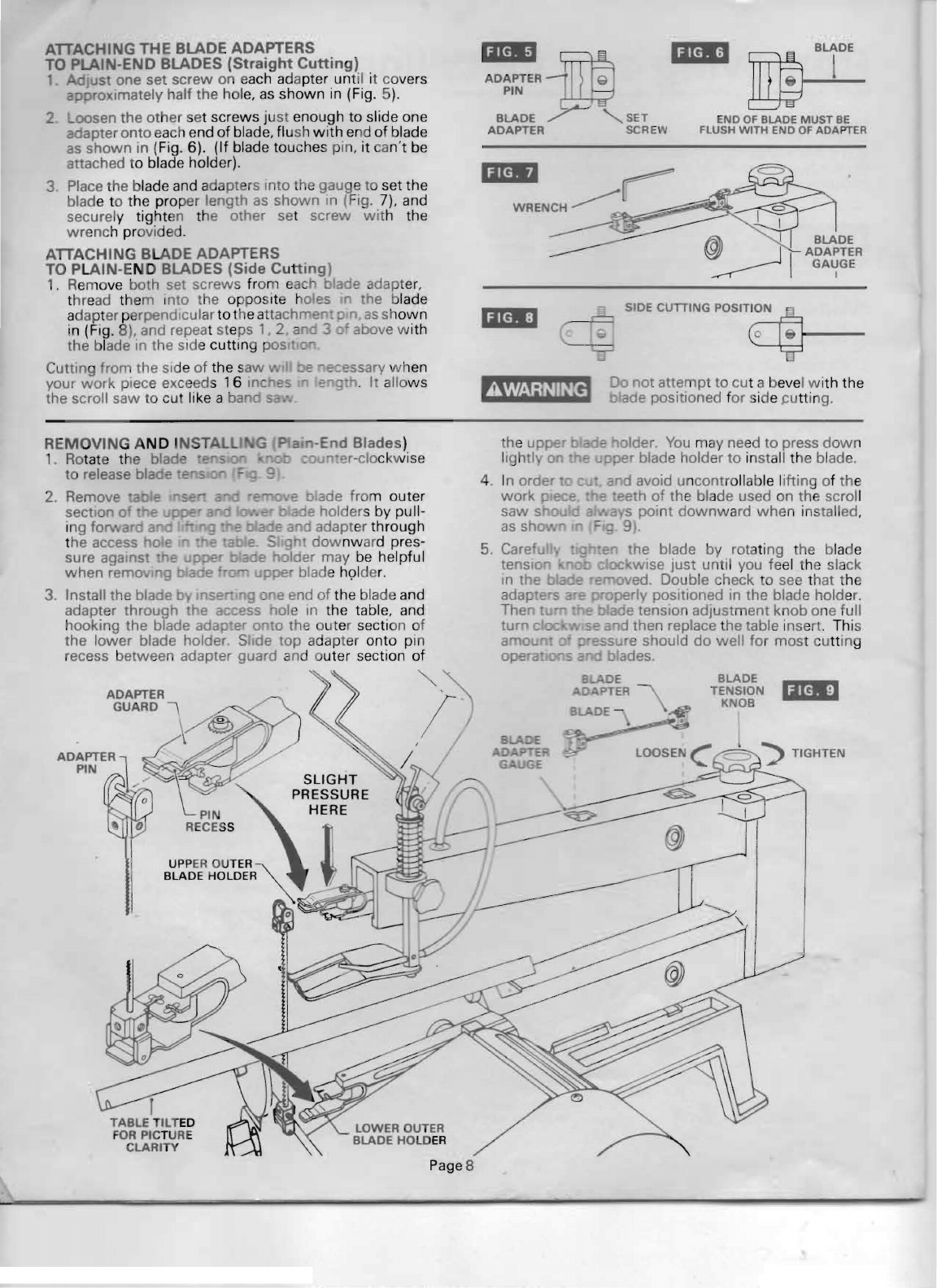
ATTACHING
THE
BLADE ADAPTERS
TO PLAI
-END
BLADES
(Straight
Cutting)
1. Just
one
set
screw
on each adapter until it covers
approximately half the hol
e,
as
shown
in (Fig. 5
).
2 oosen the
other
set screws ju
st
enough to slide one
adapter
onto
each end
of
blade, fl ush
with
end of blade
as
shown
In
(Fig. 6). (If blade touches pin,
it
an't be
attached to blade holder).
3 Place the blade and adapters Into the gauge to set the
blade to the prop
er
length as
shown
In
(Fig. 7). and
securely tighten the other set screw
wit
h the
wrenc
h provided.
ATTACHING BLADE ADAPTERS
TO PLAIN-END BLADES (Side
Cutting)
1. Remo
ve
both
set
screws from each 0
ade
adapter,
t
hr
e
ad
them IOta the opposite ales he blade
adapter perpendicular to the attachl"T'e • p
...
as
sh
own
in
(F
ig. 8). and repeat
st
e
ps'.
2 an 3
of
above w ith
the blade in the side cuttlOg pos .
Cutting from the side
of
the s
aw
be
ec~ssary
wh
en
your
work
piece exceeds 1 6
inC
f!
fr
. It allo
ws
the scroll
saw
to cu like a
band
'I.i
~
'i.'
ADAPTERi
Q
PIN
Y-'
BLADE SET END
OF
BLADE MUST
BE
ADAPTER SCREW FLUSH WITH END
OF
ADAPTER
'i'*'
~
WRENCH
~
SIDE
CumNG
POSIT~
__
_
Do
not
attempt
to
cut a bevel w ith the
AWARNING
bade
positioned f
or
ide pu
tt
in
g.
• I
C>
~I
II
~I
liliM:'
REMOVING A
ND
I
NSTAL
1
Ro
tate the blade
2.
to release blad'" ,.",."",,,,n
section 0 e
Ing fo rd a
the access 0 F
sure against E
when
remo. 9 a
3. Install the blaoe b I
se
adapter
through
the a
hooking the blade ada
er
0
to
the ou ter section of
the
lower
blade holder. S de top ad
apt
er onto pin
recess between adapter guard and outer section
of
""
ADAPTER
GUARD
\
RECESS
UPP
ER
OUTER -
BLADE HOLDER
r
TABLE
T
ILT
ED
FOR PICTURE
CLARITY
LOWER OUTER
BLADE
HOLD
ER
the uppe
lightly on -holder.
You
m
ay
need
to
press
dow
n
pper blade holder to in
st
all t
he
blade.
n the blade
by
rotating t
he
blade
c oc
wise
just until you feel the slack
'"
oved. Double check to see that the
operly pOSitioned
In
the blade holder.
!:: b ade tension
adjustment
knob
One full
"
......
,
.....
v,"'e a d then replace the table insert. This
~ssu
e should
do
well
for
most cu
tt
ing
sad
blades.
BLADE
TENSION
Ijl41
KNOB
Page S

Moun ing the scroll saw to a bench
.
1.
W h n
mounting
this saw to a wo
rkb
ench, a solid 4.
Ex
a
mp
le
of
mounting this S ro
bench is pref
err
ed over a pl
yw
ood bench w he
re
noise and
vi
br
ation will be more not
ic
able.
2.
Ha
r
dwar
e to
mount
this saw to a workbench is NOT
SUPPLIED
wi
th the saw. However,
we
rec
o
mm
en SCROLL S
~
ASE
the hardware used be no sma
ll
r than the fo
ll
owmg.
Quantity
Description
4 H H
ead
Screws, 1/
4-20
Length R
eq
uired
4 Flat Washers,
9/32
1.0
.
4 Lockwasher,
9/32
1.0.
a H
ex
Nut
s.
1/
-20
3.
S
ft
foam pad
to
place be
tween
your scroll
saw
and
workbe
nch is NOT s
upp
lied
wi
th the saw. However
w e highly recommend the use of such a pad
('
redu
ce
nO
ise and
Vib
ration.
Quantity
Description
1 Soft foam pad, uch
as
ca
rpet padding,
24" x 1 2" x 1
12'
Do NOT overtighten
mo
unting bolts -leave some cus
hlo
in the foam pad f r absorbing
nO
i
se
and vibration.
WARNING:
Always remove the plug from
power
source
be
fore making
an
y adjustments on your saw.
ATIENTION
.
Whe
n in
se
rting the front right h
ex
head
screw, it
will
be n
ec
essary to remove 5 screws and
re
mov the fan box cover.
WORKBENCH •
5. If you prefer
to
mount
your
saw
to
a leg set
we
AlT
C I G THE
MAGNIFIER
LAMP
re
comm
end t he leg set
for
bench top tools
whi
ch is TO
YOU
SCROll
SAW
(Available
as
Accessory)
available th
rough
Dr
em
e
!.
The n
umber
of
this leg sert rou
nd
end of lamp base into the
s
et
is
164
35.
Th
iS
leg set is an optional acce
ssor
y e rear
of
saw
as
shown
in (Fig.
12
).
an
i
ns
tructions
to
mou
nt
the scroll
saw
to
this
leg . w ays be sure to pos
it
ion the cord
set are
inclu
d
ed
in
the
leg set package. ay rrom
cL
Jlt
i n area.
'iN"
li(40
Page 9

o eration
PLEASE. read
an
d understand the foll
owing
items a
bout
your
scroll
saw
befo
re
attempti
ng
to use the saw.
The saw does not cu t
wood
by itself.
You
a
llow
the
saw to c
ut
wood
by
gu
iding the
wood
into th e blade
as
it moves.
2. The blade teeth cu
ONLY
on he
down
stroke.
3. The drop f
oot
should a ays be
10
erea until it just
rests on top of
he
.'orkplece.
4 . The blade guard should always be
ered
over the
blade during cu
ng
operation.
5.
You
must
eed
th
e
wood
into e b de
slow
ly
because the
Teeth
of
the blade are e sma
ll
and
they c
an
only remove
wood
_ e are on the
down
stroke.
Th
e blade
wil'
Ie.
ards when
applYing feed pressure. Too m pressure will
cause blade
br
e
ak
age.
6. There is a learning cun.
to use this
sa
w. D
unng"
that some blades
IA
a
the saw and rece e
blades.
7 . Best resul·s a e a
"n
1:
ttng
..
lOad less th
an
one Inch c
B.
When
cun
n9
wood
thicker than one
In
h the user
must feed the
wood
very
slow
ly Into the b
la
de and
take extra care not to bend
or
twist
the blade
wh
ile
cutting in
order
to maximize blade life.
9. Teeth on the scroll blades wear out nd as such
must
be replaced frequ
en
tly for best cu
ttin
g
re
sults.
Scroll
saw
blad
es
generally stay sharp for
Yz
ho
ur to
2 hours
of
cutt
ing,
MAKING
INT
ER
IO
R SCROLL CUTS
1. One
of
the featur
es
of
this saw is that it an be used to
make scroll cu ts on th interior of a bo
ar
d w ithout
breaking
or
cutt
ing i
nto
the outline or peri
me
ter of
the board.
AWARNING
TO
AVOID ACCIDENTAL STARTI
NG
,
ALWAYS
TU
RN
SWITCH
"O
FF
" AND
REMOVE
PLUG
FR
OM POWER SOURCE
BEF
O
RE
REMOVING
OR
REPLACING THE BLADE,
2.
To
m
ak
e interior cuts in a board , remo
ve
the scro
ll
bladtl
as
e plained on pages 7 and 8 . .
3.
Drill a
Y4
inch hole
in
the board you
will
use to make
interior cuts.
4 . Place
th
e board
on
the saw t
ab
le
wi
th the hole
In
tne
board over the ac
ce
ss hole in the
ta
ble.
5. Ins
ert
blade through hole in boar
d,
install blade a d
adjust
blade tension.
S.
Lower
drop
foot
unt
il
it Just rests on
top
of
the
workpiece,
lower
blade guard and you're ready to
begin cutting.
7.
When
finished making the in
ter
ior scroll cuts si
mply
remove the blade
from
the
blade holders.
as
deSCribed
on
pages 7 and 8 and remove the board from the
table.
Pa
ge 10
10
To g accurate cuts be prepared to compensate for
the b a e s endency to
follow
the
wood
grain
as
you
are c
oos g a blade to use
it
h yo
ur
scro
ll
saw
t;
·ollo
wlng
ca
refully:
•
arrow
blades should be used to scroll
ood
(
~
inch thick
or
le
ss).
over ~ inch thick. u
se
wi
der blades.
•
£:
oackages state t
he
ize or thickness
ch that blade
is
intended to cut. and
s
ze
of
curv
e)
whi
ch can be c
ut
w
it
h
s can't c
ut
cu
rv
es
as tight or sm
II
as
•
E-S
•
~d_s
work
well
only on thinner
wood
5 Inch lo
ng
, pin or plain-end type
ccessones on page 11 ).
13. t:r hen
cutt
ing
pl
yw
ood, w hich
is
en sawing
woo
d w hich
is
thicker
c blade stroke; and
whe
n
sa
w ing
•
en
SIde
pr
essure is placed on the
14 t:C
DUS
and
no
n-ferrous metals. th e
used at very
slow
speeds. They
on machInes
that
have
va
ri
ab
le speed
uld
be
lubncated
with
beeswax, or
"""'"""'tn"
a I
'je,EI
DROP FOOT
AND
BLADE
GUARD
RAISED
FOR
PICTURE
CLARITY
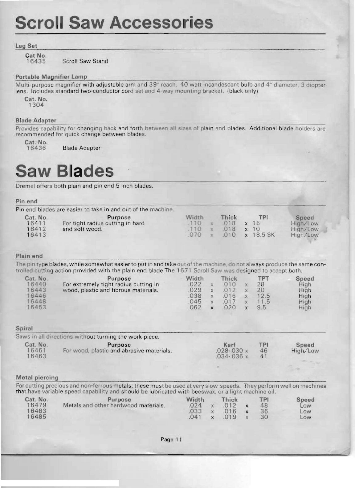
Scro I Saw Accessories
Leg
Set
Cat
No.
1
6435
Sc
roll Saw Stand
Portable
Magnifier
lamp
Mul
ti
-purpos
e magnifier
with
adjustable ar m and
39
reach.
40
watt
Incandescent
bulb
and 4" diametEr 3
diopter
len
s.
Includes
st
an
da
rd
two-
c
onductor
cord set and
4-way
m
unting
bracket. (black only)
Cat
.
No
.
1304
Blade
Adapter
Provides capability
for
changing back and
fort
h bet
.....
ee
:a
_I
Z.S
ot
plain end blades.
Addition
al bla de holders are
recommended
for
quick cha nge betw
ee
n blad
s.
Cat.
No.
16436
Blade
Adapter
Saw
Bl
ades
Dremel o
ff
ers both plain and pin end 5 inch blades.
Pin
end
Pin end blades a
re
easier
to
take in and o
ut
of
the
machine.
Cat.
No.
Purp
ose
Thick
TPI
Speed
16
4
11
Fo
r ti
ght
radi us c
utting
in hard
018
x
15
Hlgh/L
w
1
64
12 and
soft
wood
.
018
x
10
High/Low
1
64
13 _
010
x
18.5SK
Hlg
hlL
ow
Plain
end
The
pm
ype blades,
while
so
mewhat
easier to
pu
t in and
ta
ke
out
of
the
mac m-
not
al
ways produce rhe
sa
me con-
ro
Ie
cu
tt
ing action provid
ed
wit
h
th
e plain end b
la
de.The
167
1 Scroll
Sa
as esign
ed
to
accept
bot
h.
Cat.
No.
Pu
rpose
Width
Thick
TPT
Speed
6
40
For
extremely
tight radius
cutti
ng in
.022
X .0 0 x
28
High
16
3 w ood, plastic and
fibrous
matenals. .
029
x
.012
x
20
High
16
....
6
.038
x .
016
x 1
2.5
High
68
,
045
x
.017
x 11.5 High
16.
53
.
062
x
.020
x 9.5 HIgh
Spiral
Saws 'I"' a I OIrec Ions
with
out turning
the
work
piece.
Cat.
No.
Purpose
Kerf
TPI
Speed
16461
For ood, plastic and abrasive materials. .
028-.030
x
46
Hig
h/Low
16463
.034-.036
x
41
Metal
piercing
for
cutting
precious and
non-ferrous
metal ; these
mus
t be used
at
very
slow
speeds. They
perform
well
on machines
that have variable speed capabIl i
ty
and should be lu bri cated with beeswax.
or
a
light
machine oil.
Cat.
No.
16479
Me
ta
Purpose
ls and
other
h
ardwood
ma
Width
terials.
.024
x
Thick
.012
x
TPI
48
Speed
low
16483
.033
x
.016
x
36
Low
16485
.
041
x
.019
x
30
low
Page
11
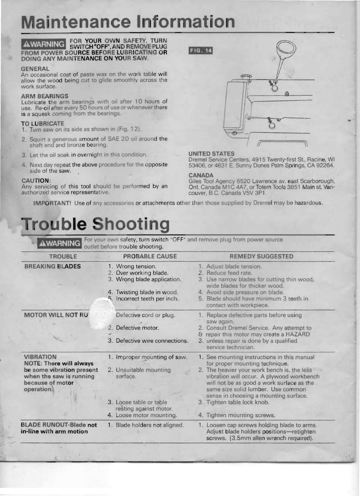
Maintenance Informatio
FOR YOUR
OW
N SAFETY. TURN
AWARNING
SWITC
H "OF
F'
.
AND
RE
MOVE PLUG
FROM
POWER SOURCE BEFORE LUBR ICATING OR
DOING
ANY
MAINTE
NANCE
ON
YO
UR SA
W.
GENERAL
An occasional
coa
of
paste
wa
on the work table will
allow the
wo
od being
CUt
0 glide smoothly across the
work
surface.
ARM
BE
ARINGS
Lubricate the arm
Dear
gs I a er
10
hou
rs
of
use.
Re-
oil a
fter
eve
50
ours of use enever the
re
is a sque
ak
corning ro the bearings
TO LUBRICATE
1.
Turn
sa
n Its side
as
shown
In
F 2).
2 SquIrt a generous amount
of
S around the
shaft end and bronze
be
aring.
3
let
the oil soak in over ight
In
4. Next day repeat the above proced
sIde of the saw.
CAUTION:
Any
servicing of this tool shaul armed by
an
authOrized service representativ
••
(.C]
If
\\
UNITED STATES
Dremel SeNlee Centers, 491 5
Tw
enty-first St.. Racine,
WI
53406, or 463
E.
Sunny Dunes
Palm
Springs.
CA
92264.
CANADA
Giles
Tool
Agency
6520
Lawrence
avo
east Scarborough,
Ont. Canada C 4A 7,
or
Totem Tools 3
851
Ma
in
st.
Van-
couver B.C. Canada V5V 3P1 .
IM
PO
RTANT! Use
of
an a
es
or attach ments other than those
Su
piled by Dremel may
be
h
az
ardous.
rom power source
TROUBLE PROBABLE CAUSE
AEMEDY
SUGGESTED
AWARNING
ooting
BREAKING
BLA
DES
MOTOR
WILL
NOT RU
1.
Wrong tension .
2. Over working blade.
3.
Wrong
blade application.
4. Twisting blade in wood.
~
.
Incorrect teeth per inch.
Defective cord or
pl
ug.
2. Defective motor.
3. Defective wire connections.
sawagam
2.
Consul' Dremel Service. Any a
tempt
to
& repair
thiS
'TIotor may create a HAZARD
3. unless repa r
IS
done by a qualified
service technICI
an
VIBRATION
NOT
E:
The
re
will
always
be
some
vi
bra
t
ion
pres
ent
when
the
saw
is
running
because
of
m
ot
or
operation
.
1.
Im
pr
per
lTlou
nting
of
saw.
2. Unsuitable mounting
smface.
3.
Loose table or table
resting
aga
i
nst
motor.
4. Loose motor mounting.
1.
See
mounting instructions in
this
manual
for proper mountIng techni
qu
e.
2. The
~eavler
your
work
bench is, the less
vibratIon
will
occur. A plywood workbench
will
not
be
as
good a
work
surface
as
the
same size solid
lum
ber. Use common
sense in choosing a mounting surface.
3.
Tighten table lock knob.
4.
Tighten mounting screws.
BLAD
E RUNOUT-Blade
not
1.
Bla
de holders not aligned. 1. Loosen cap screws holding blade
to
arms.
in-l
i'ne w
ith
arm
motion
Adjust blade holders
poS
Itions-re
t
ight
en
screws.
(3.5mm
allen
wr
ench required).

DREMEL.:
MODEL
1671
TYPE
2
SCROLL
SAW
,~
55
-~
r
..
,,;
..
..
',
~o
~
\
56
j'"
",
.
57
" 'I / 65
/_
'V
.. . ' -
Ii
"
~~
/ 61
24
<0
• <
~
v
\ill .
..
58
-
Ii
I i I
<i.
62,,,Ii'/
"
~'
i
23
.
'Il;j"
'I
30
I
....
>
~_
/
.
, J "
..
"'
"..,.
,. I '
f,t
/~
/'
)~,
~
~
~
29
I '
...
.
..
....
. I . ' '
/ ,
..
,..
""
..
..-,
..
-. -63
,,
/:
1t
r
27.
t'fr
'.
25.
...ft,
·''''f,.
::---
'::.
~
..
( , 66
:'
. <
B.2
,C
' . I • •
.'
'
'''.
. "
&I
,
~
,
83
~.
_
~
_,
_ '} 35
.~--
67
~
~
..
.;)
'.'
'..
_
~Wi
"
-..,.
:"
--
22 .
.~C
36
)'
V
'£'
7
,."
.
~
lfoi\~
J .,
.
"
84
\
t..;
~
'
/~
....
, "
_/
~~
.
'-
'Y
_ ,
'"W'"
",
,.
81
,.., ' ' 4 . "
..
27
",
""
____
•
.."
,/
2
/
....
,
....
20 ., '
t.
"
25
'.
"-.
.......
' . .
42
/0'"
//
'
'
~
'1;0 ,
,)
\
.~
~
' .
__
37
<,
..
39 .J .,1 . /
"--
",
~
,
!1
•
'<.k
,>:.r('
"
~
'
'-~
.
~
.:
0
-:a,\
,
~
1t-
69
/
tl
"'<:{r'~",
'.'
<L-
."
25
"'.
'
\l--'
-I;
- •
~
,-
47
68
~
/ 1 II
~
f-"
....
"
't-
23
<.
>::::--
·3.8
·
...
:.:.:
1
44
. "'-.Jl- "
·
...
,.v\.....~
I
·
48
.,1.
of·
\,w
~
"
"
",,-,~
6
'1
Q Q
"'
,
~j
,
,
~~
"'~""'~.'
, 16 3
"
,~
49
-A (/
r,
~
:'" /
70
.
24
""
..
'..
--
I
'L,
16
32':"
~~
~
45
46
/~
-<l
\
'\"'"
_
30
"
~ ~
.
'
...
',).
11
' .
Ii
\.
A,
~
"
/
~
Q
~'
"
35
'
.•
~
/ I "
~
'
."
.....
,
~,{'"
\'
,
~'
>
/.
'
""
.
/-,~
1"~
~
, / >
,,~c
~
"'-....
..
1>
~~
~.,
.
.:--
't
'
I
-':"
"\1(.:
.,;",,,,
~<,
~
p
;-/
lrM
IA
~'-
~
'
",
~
,
26
\ .....
~
~
I
1M
..
....
%
~
~
I~
1"\
50
'-'-1\
•
v'
l I 33
2,____..
_.
./::
'.
(fP.
•
/~~
1>,'0
~'I
zt
;.:,
\
11
31/
.I 34 / '
.:;-
\
'r
'
lt~:
/ 1
Jil
,,J
C-
'T
16
•
'
",
t / J
~.~
,
h~
~~
..
"
..
~::-.
"
.
'
.. ..
26
43-
..
.
,
~
,'
}1
":-Z~""
'"
42
~
A~'..>,.
. .
~
\
,~
~
/
~=';~
'
'0
"',
y
.,,1
.1
"-
51 C'
~
IJ
~
"V
. '0, 9 "
~~
52
59
.
"'
. 1 I
..
/5
'.
.
''l-
.,
i,..
4
I.
, \ 64
~
~
• 74
.;J
~
.
~
-
~
lr
'
~'"
t::-
~~
~
1"
<~"
I,
! ( (
.'L-
5'
r'
~
'''
'"
/'
.,
;:;;
"~/
~
@
.
/ 0 "
(
.).
~
3
r(''-'l
/
""
,
."
~'
j
~
__
76
rl
72
"
~
/ v
,,'
.
I.
/
~
/'
,/
,,/
~
11
'
1
.
·t""'
~
..
- / < -
/..
,
."
"
'J
/,
'
l!'
;Il---
~
......
1\
/
/'
<."
.
//."
.p
//
/
YJ.
.
""
,
".
-
___
~
''6
...
I
~
\
~
.::'
75
,fit;
13
4-",
/ d'"
/,
I
14
"
~
~
5
78
II
I
74
. .
./
· / l 17 /
79
-~
I I
77
I
~~
.
"'
'-
'.
-:' ·
.".
. .
"'~
\ /
~
~
73
~~
., J
</;
·1.
.
""'-
~
7
\
15
18
J."
.~
,~
..
<
~"
3
'",
.
<'
~
I
,
''Qr
6/
/IIi
\
~~
8--i
\0
12
'
-'
5
80
-
"

-
--
CODE
PART
NO. NO. DESCRIPTION
1
5296183
Blade Box
5296195
Self
Tap
Screw
(8)
2
3
9730
Spring Washer
(9)
4 Hex Nu!
(6)
11489
5296196
Pan
Head Screw
(8)
5 I
5296
150 Plate Cover
6
44549
Spring Washer
(2)
7
8 5296197 Hex Head Boll
(2)
5296182
9 Base
10
5870
Hex Head Bo
lt
(4)
11
5296747 Housing
le
ft
12 Supp. Table
5296189
13 5296177 Indicator
14
4775
Round Head Screw
15 5
296
154 Brackel T
il
t
16 9709 Spring Washer (
3)
17 52
96165
Sp
ri
ng
Fl
at Washer
(2)
18
670
34
19 5296198 Hex Head Bolt
Spring
20
52
96
749
21 52
96
199 Bolt Tension
22 5296
201
l ower Rocker Arm Assy.
23
Spring W
ash
er
(2)
1734
24 306064 Hex Head Bo
lt
(2)
Bearing
Fla
nge (
4)
25
5296 159
Self Tap Screw
(2)
26
52962
02
Cap Head Screw (4)
27 52962 17
Re
tai
ne
r
(2
)
5296 164
28
5296213
29
DREMEL
F
orm
No.
5296679
4/
91
Upper Roc ker Arm Assy,
UNITED STATES
PART
NO.
CODE NO, DESCRIPTION
1309 Hex
NUl
(2)
i
30
31
3061 27 Hex Head Bolt
32
5296166 Spacer Beining
5296167 Washer
33
5296203
li
nk
Ass~mbly
34
35
30483
7 Round H
enel
noll
(·11
36 Set Plate(2j
5296179
~
17
5296187 Holder UPpt't
:)8
313236 Hex Socket Boft
Set P
la
te
Upper HOlder
3H
5296508 I
40
Holder
lo
wer
5296186
41
~1599
Tooth Washer (
21
42
Hex Socket Head Bolt (2 )
529fi205 j
Ta
ble Insert i
43
52~J6746
Blade Adapter
(2
)
44 1
13436
i
Blade
(P
in T
yp
e)
I
45
I
Blade
(P
lain)
46
47 5296 152 Guard Blade
26248 Tooth Washer
48 -
472 1
~
lox Sm.kel
Head
Bo
lt
49
B(ll1
Collnr
(2
)
50 52961
75
52961 94 Motor
51
52 52
962 10 cocen lll
!...
53 529619 1
T<lblf!
He
)(
Socket He
ad
Boll
54 2
9359
P
VC
Pipe
55 52
96
1
62
Su
ppo
rt
Ro
d
56 52
96
1
76
5296745
57 Bellows
lock
5296744 Bello
ws
58
WRITE FOR CURRENT PRICES '
NO
C.O.D. 'S
OUTSIDE
OF
CONTINENTAl. UNITED STATES
Dremel Service Center,
4915
Twenty-first
Sf..
Racine,
WI
53
40
See yo
ur
loc
al
distribut
or
or write to Dremei.
Dremel Service Center.
463
1 E. Sunny Dunes, Palm Sp
ri
ng
s,
CA
92
262
49
15 TwentY'first St., Racine,
WI
53406
EASTERN
CANADA
WESTERN
CANADA
Giles
Tool
Agency 6
520
L
aw
rence
av
o eas
t.
Scarborough, Onl. Canada M 1 C 4A 7
Totem
Tools 3851 Main sl. Vancouver, B
.C.
Canada V5V 3
P1
491521 s l
Street
RACINE. WISCONSIN
53406
U.S.A.
PR
INTED
IN
U,
SA
CODE
NO
'.
PART
NO. DESCRIPTION
~Jj
9
~-
5296247 Tooth Washer
60
5296748 Housing Right I
61
313236 Hex Socket Head Bolt
62 29234 Washer (2)
63
5286
184 Transparent Guard
64
529620;
Cap Head Screw
65
5296229 Relaining Ring
66
5296215
Spring
67
5296163
Brass Pipe
68
529
6246
Fl
at
Washp.r
(2)
69
5296216 Spring Washer
70
5296185
Fa
n Box
71
5296
190 Switch Case
72
5296218 On/Off Switch I
7~3
5296219
Hi
/lo
Switch
74 5296220 Self
Tap
Screw (2)
75 5296153 Switch COlier
76 52962
21
Cap Head Screw
(4
)
77
5296172 Knob
78 26111
Fl
at
Wa
sher
79 5296222
St
r
ain
Re
li
ef
80
5296223 Power Supply Cord
8 1 5296242 Knob
82 5296243 Set Screw I
83 5296244
All
en Wrench (4 m
m)
84
5296245 A
ll
en
Wr
ench
(2
,5 mm)
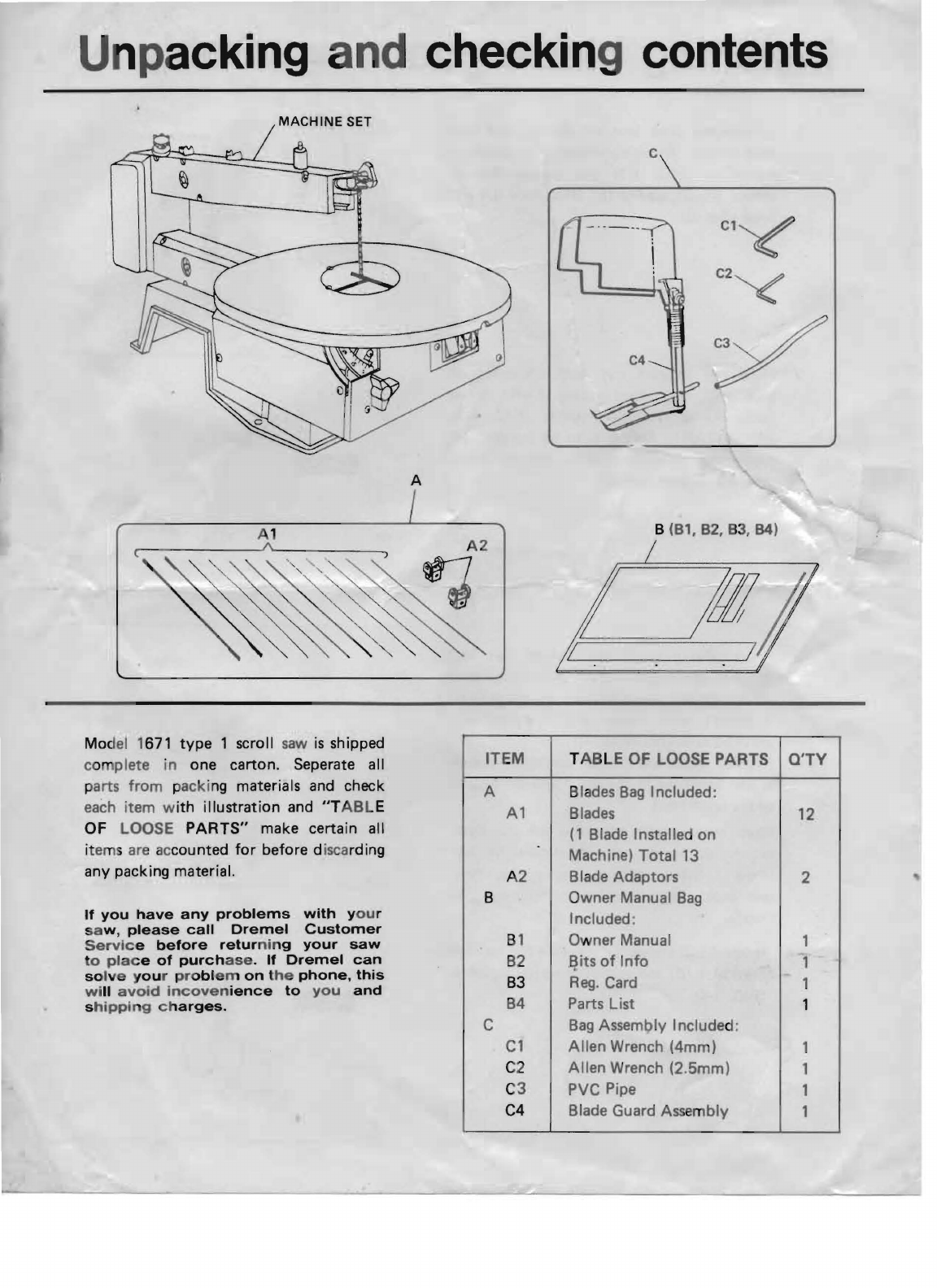
Unpacking
nd
checking
contents
A
c
C1~
C2~
Y
8
(81,82,83,84)
(
Mo
del 1671
type
1 scroll
saw
is
shipped
c
om
plete
in
one carton. Seperate all
parts
from
packi
ng
materials and check
each item with
illustration
and
"T
A
BL
E
OF LOOSE
PARTS"
make certain all
it
ems
are
accounted
for
before d
isca
rding
any packing material.
If
you
have
any
problems
with
y
ou
r
sa
w,
please
call
Dremel
Customer
Servic
e
before
retur
ni
ng
your
saw
to
pla
c e
of
purch
ase.
If
Dremel
can
so
l
ve
y
ou
r p r
oblem
on
t
he
phone,
this
w
ill
avoid
incoven
ience
to
you
and
s
hipping
c h
arges.
ITEM
T
ABLE
OF LOOSE PARTS O'TY
A Blades
Bag
Included:
Al
Blades 12
(1
B lade I nsta lied on
Machine)
Tota
l 13
A2 B lade Adaptors 2
B Owner Manual
Bag
Included;
B1 Owner Manual 1
B2
E}
its
of
Info
1
B3
Reg.
Card 1
B4 Parts List 1
C
Bag
Assembly Included:
Cl
Allen
Wrench (4mm) 1
C2
Allen
Wrench (2.5mm) 1
C3 PVC Pipe 1
C4 Blade Guard Ass
em
bly
1

In
ta
il
ing
bl
ade
guar
d
se
mb
ly
1.
Loosen
the
drop
foot
set scr.
(C)
and
br
ass
pipe set scr.
(A)
wit h
pro
vi
ded
all
en
wrenc
he
s
shown in
(F
I
G.
1-1)
and
remove
the
set
screws
(A,
C), washer (E).
drop
foot
(0)
and
brass
pipe
(B).
2.
Pl
ace
the
support
rod
into
it's
mount
ing
h
ole
(
FI
G. 1-2),
then
lo
cking it
with
sc
rew
knob
(F)
at
available position (FIG. 1·3).
(IMPORTANT: Spring
is
to
be installed
for
suppo
rtillil
g-u
ard
assembly
not
to
apply
pr!#
$S
ure
to
work
surface)
3. In
sert
brass pipe
(B)
and secured
drop
fo
ot
(0)
into
the
support
rod. Hand
ti
ghten
their
set
screws and
make
sure
the
(B,
0)
posit ion
is
correct. Then tighten
the
set screws
with
pr
ovided wrenches (F
IG.
1·3).
(N
OTE:
A
fter
use
the
provided a
ll
en wrenc
h·
es
can
be
stored
in
the
bl
ade
bo
x on
th
e side
of
th
e scroll saw).
Wh
en mounting
or
relocating
the
saw
dust
blower nozzle,
do
not
over tighten
the
set
screw.
Stop
tightening when you feel
resistance. Over tightening can damage
the
nozzl
e.
4. Insert
the
pvc pipe
(H)
one
side
end
into
the
brass pipe
(B)
and
plug housing (G) shown
in
(F I
G.
1-4).
U
ttI'i
l
iiI'·'
j
bt."
8
iil.i'
o
SUPPORT
RO~
PVC PIPE H
