Duali DE-PCA20 Portable Card Checking Machine (RFID) User Manual Vertical
Duali Inc. Portable Card Checking Machine (RFID) Vertical
Duali >
Users Manual

BEIJING LINE 10
AUTOMATIC FARE COLLECTION PROJECT
User Guide for PTCM(Portable Card Checking Machine)
( Model Name : SA-74PS01, SA-74PB01, SA-74PC01)
REVISION NUMBER: 1.00
27 February, 2007
SAMSUNG SDS
Copyright
ⓒ
2006 Samsung SDS Co., Ltd. All rights reserved. You are strictly prohibited to copy,
disclose, distribute, or use this document in part or as a whole for any purposes other than those for
which this document is disclosed. This document is copyrighted and contains confidential information
and other intellectual property rights of Samsung SDS Co., Ltd. Any unauthorized use, copy,
disclosure or distribution constitutes infringement of Samsung SDS’ intellectual property rights.
1. Outline
This Device is portable smart card reader and you can use this Device as
electronic cash or token Marker, Device for purchase, Device for load
according to service provider. And this one is communicated with PC or
other upper device using USB. There are 4 SAM in this device, so this one
can support several kinds of electronic payment system. And It is easy to
make program for service provider, because this device use WINDOWS CE for
OS. Basic data in this device is as following.
Item Specification note
CPU ARM9, S3C2410 32bit RISC
SIZE 215mm(w) x 86mm(l) x 37mm(h)
Weight Under 300g Not include Battery
Battery Capacity 3.7V / 2200mAh Over 4 hours to use
Program memory1 32MBYTE NAND FLASH WIN-CE part
Program memory2 32MBYTE NAND FLASH USER APP, DATA part
Data memory 64MBYTE SDRAM Execute program
HOST Communication USB1.1, RS-232 Basic
RF Card that can be used ISO 14443 A/B, Mifare
Contact Card that can be
used
ISO 7816 T=0
Security Module 4 SIM SOCKET
Electronic Specification
of Battery charger
Over DC12V, 700mA Adapter
1
2. Configuration
2
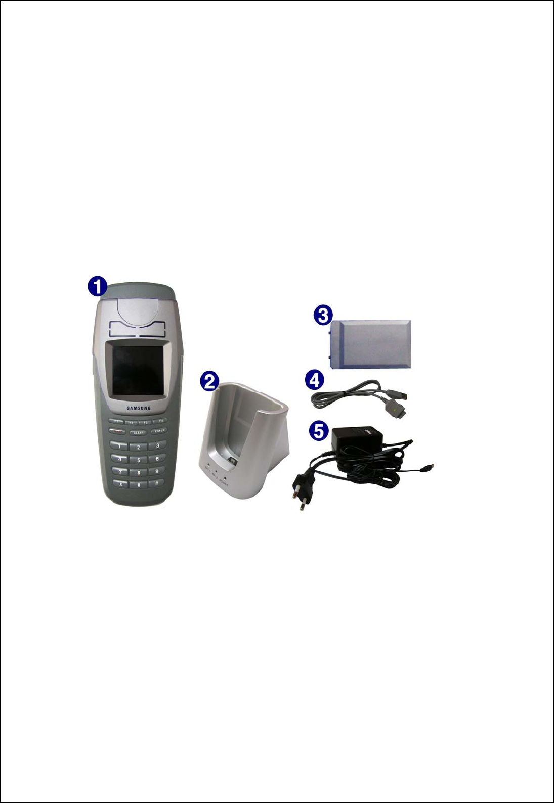
2.1 Device Configuration
- Portable Card Checker
(Main PCB, Contact Card/ RF Card/ SAM Control PCB, Keypad PCB, LCD)
- Battery Charger
- Battery 2 EA
- Adapter
- Communication cable
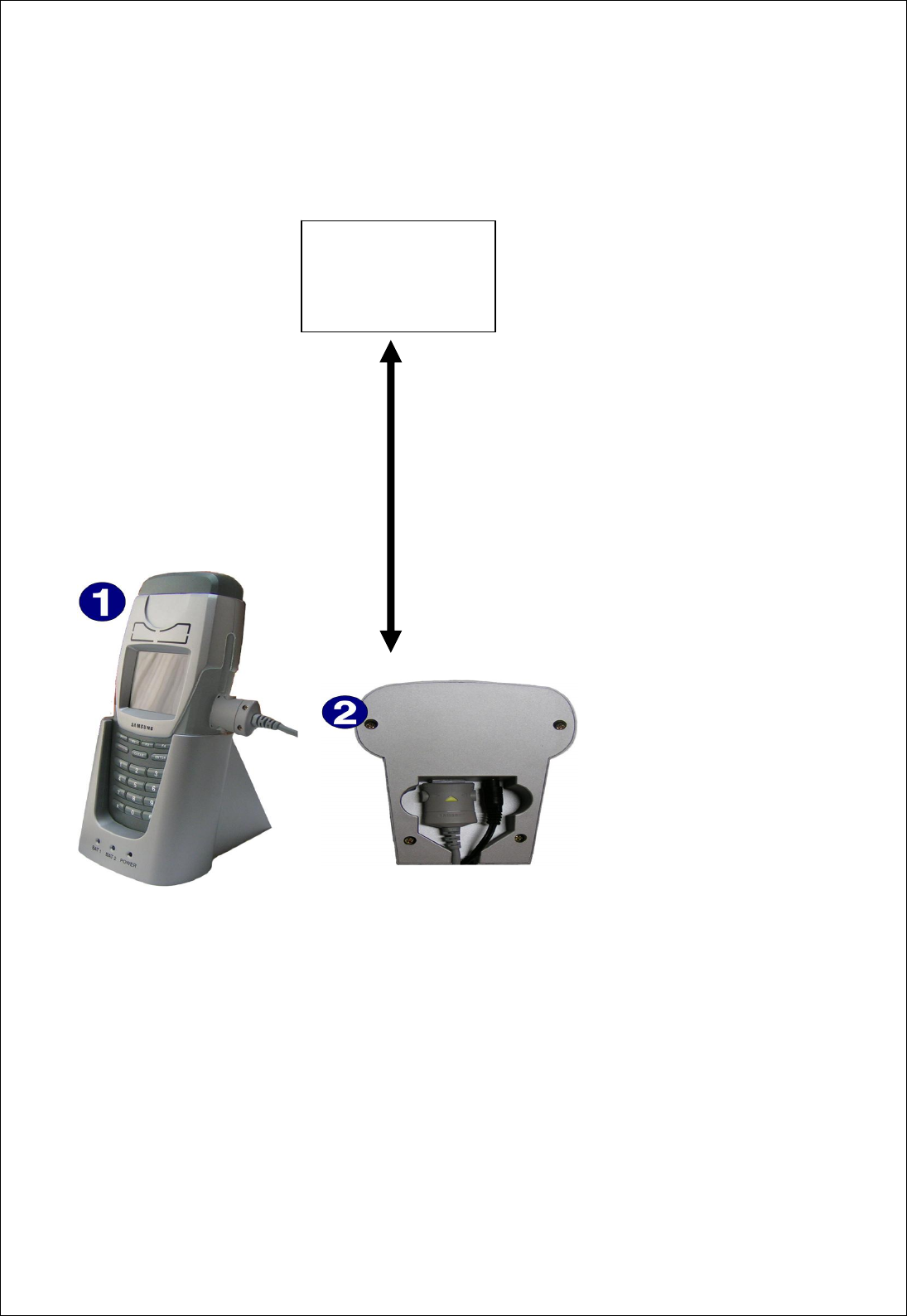
2.2 System configuration Diagram
3
Upper part Device
USB Communication CABLE
CRADLE (Battery Charger)
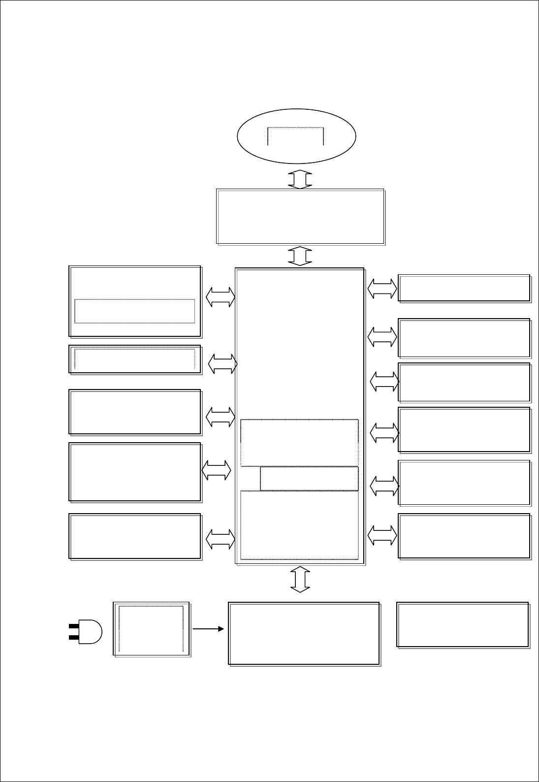
2.3 Main board Block Diagram And Explanation
Figure 2-1 figure
4
CAD (Card Acceptance Device)
ISO 14443A/B, Mifare
Antenna
MAIN CPU
ARM920T Core
32bit RISC Processor
RTC 내장
RS232
Flash Memory
32MB
(
B/L 200000
)
SIM SLOT x4
for SAM
BUZZER
DC/DC
CONVERTER
KEYPAD
19Keys(0~9#,F1,F2,F3,F4
,PWR,ENT,CLR)
AC/DC
Adaptor
Color TFT LCD
LED BACKLIGHT
USB I/F to SC
Flash Memory
32MB
(
WIN-CE
)
Boot ROM
SDRAM Memory
64MB
Battery
3.7V
/
2200mAh
- MAIN CPU: Main CPU is Samsung ARM9 Core S3C2410. And this CPU is 32bit
RISC CPU. This CPU has RTC, 2 UART, USB.
- CAD(Card Acceptance Device): The part for reading Contact Card, 4 SAM and
Contact less Card.
- Contactless Smart Card Standard: ISO14443 Type A, Type B, Mifare
- Card communication Speed: 106Kbps
- Range for reading: 50mm(Card), 30mm(Token)
- Contact Smart Card Standard: ISO7816, T=0
- Contact Smart Card Slot: User Card(1), SIM Type(4)
- LCD : 960 x 240 Color TFT LCD(LED Backlight)
Parameter Specification
Screen Size 2.5 Inch
Display Format 960 * 240
Active Area 50.4mm(W) * 37.8mm(H)
Dot Pitch 0.525mm(W) * 0.1575mm(H)
Pixel Configuration R.G.B Delta
Outline Dimension 60.73mm(W) * 47.07mm(H) * 2.54mm(T)
Weight 12g
Operation Temperature 0 ~ 60 ℃
Storage Temperature -25 ~ 80 ℃
- Buzzer: Control Frequency using Buzzer connected with Timer Output Por.
- DC/DC Converter: All part that create 5V, 3.3V, 2.0V power for executing
using Battery power.
5
- Keypad: There are 19 button such as 0~9,#,*,F1,F2,F3,F4,Power,Enter,Clear.

- SIM Slot: There are 4 SAM Slot in Main board and CAD part control this
SAM slot.
- Data memory: 64MBytes SDRAM
- B/L Memory: 32MBytes NAND Flash
- Program memory: 32MBytes NAND Flash
- Boot ROM: 64Kbytes Flash
- RS-232: Communication port for Debug
- USB: USB is used as communication part when Device is connected with
upper Device using USB.
- RTC Battery: RTC is on CPU. And when power is off, RTC is running using
other battery.
- Battery: Lithium ion or Lithium polymer, 3.7V/2200mAh
- Minimum waiting time is 6 hours.
- Enable to detach and to check card over 1500 times.
- Under voltage notification
- CRADDLE: Charger Module
- Input power: Adapter power (DC 12V)
- Lithium ion(or Lithium polymer) For Battery charger.
- Charging time: Under 4 hours
- Over charge protection
- Detect decrease rate of power.
- The number of charging and discharge: Over 500 times.
- Battery weight: 66g
- Adapter: Over Power 12V, 700mA.
- Mast cell burst Factor(MCBF): Over 100,000 times
- Mean Time to Repair(MTTR) : Under 10 minutes and easy to maintenance.
6
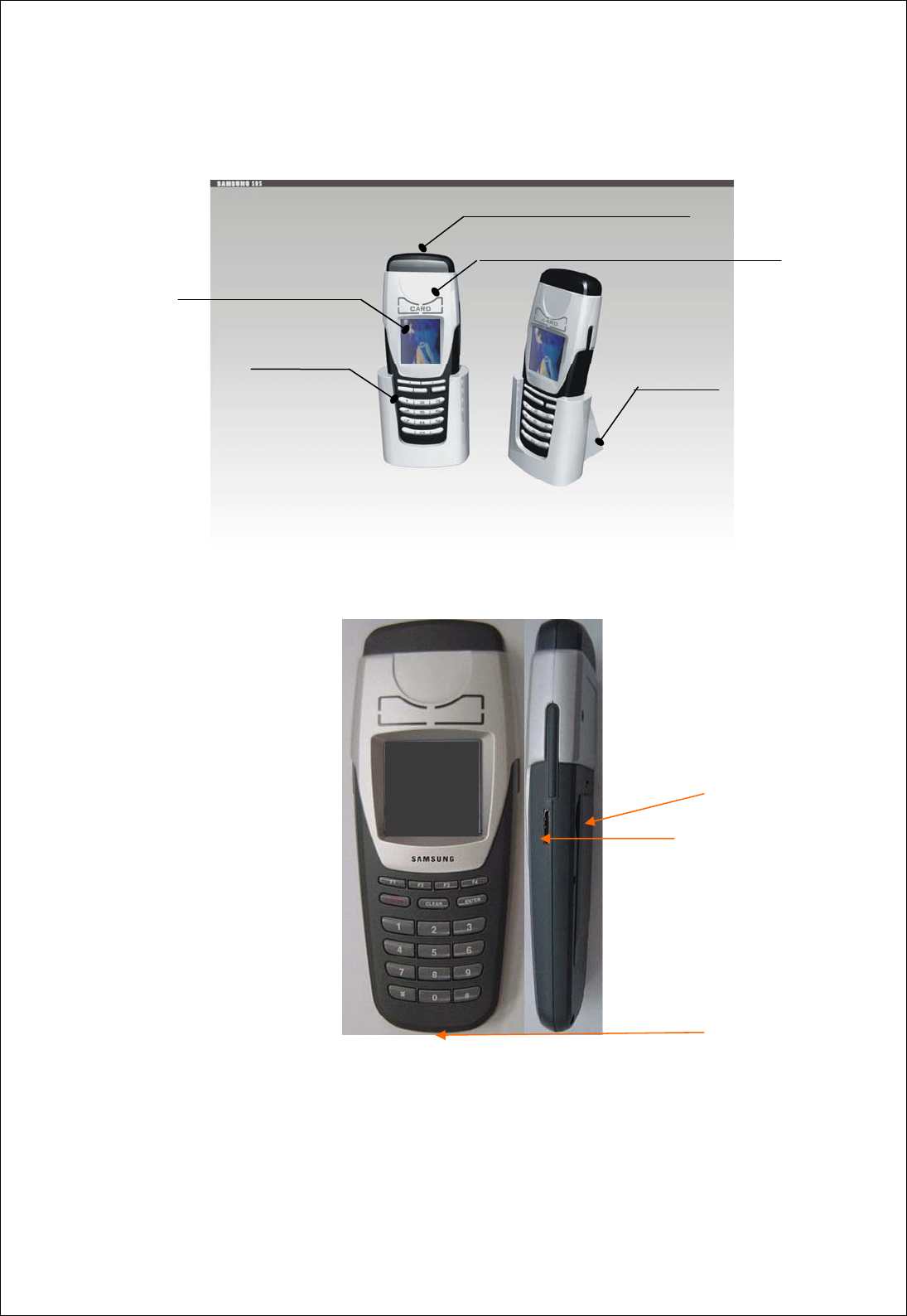
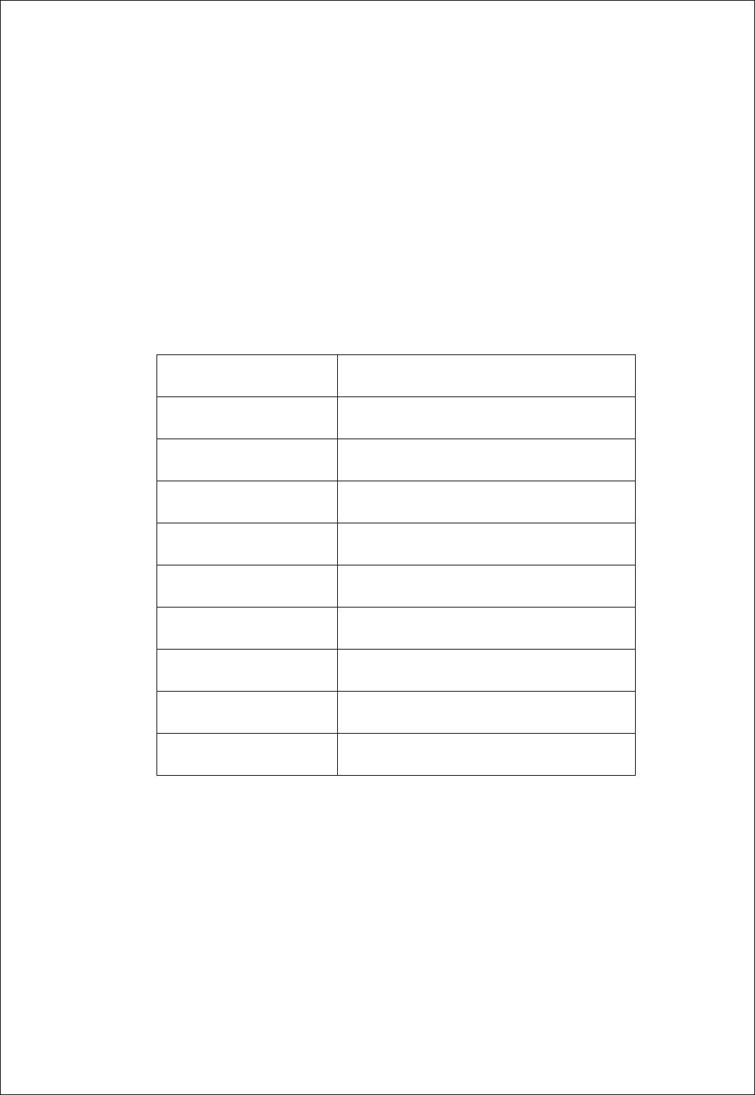
3. External Specification
3.1 Device Visual Diagram
Figure 3-1 figure
Battery
USB
USB & Power
3.2 External Size
- 215mm(w) x 86mm(l) x 37mm(h)
3.3 Weight
- Under 300g(Not include Battery)
7
960*240 LCD Display
Card hole
Contact/Contactless IC Card Reading Part(Antenna)
Battery Charger
Button

4. Electronic Specification
4.1 Power Specification
- Input Power: AC 220V / 50Hz
- Adapter output power: DC 12V
4.2 Current (3.7V As standard)
- Minimum use: Under 170 mA(Waiting status)
- Maximum use: Under 460 mA(Checking card, LCD Back Light ON)
4.3 Battery Specification
- Output power and capacity: 3.7V / 2200mAh
- Lithium ion or Lithium polymer
- Waiting time: Over 8 hours
- Over 4 hours to use
- Charging time: Under 4 hours.
4.4 RS-232 Specification
- Communicate port for Debug
- Communication Specification: 8 Data, 1 Stop bit, No Parity,
115200 bps
8
4.5 USB Communication Specification
- Support Over 10Mbps

5. Function Specification
5.1 Host Communication Function
- Enable to Load and download data to upper Device using USB.
(You can download all parameter and data, upload data of checker using this
function.)
- It is easy to make application program for service provider, because it
uses Windows CE as OS.
- Card data execute time has to be shorter than 300ms.
- Support Function for test and setting and this function are as following.
* Setting time
* RF Test
* Contact IC Card and SAM test
* Select slot number that SAM Card is connected
* Battery test
* Check Residual Quantity of Battery
* Setting Sleep Mode time
* Setting use LED or not, setting time to use LED
* Dual Driver Test(RF ON/OFF, BUZZER ON/OFF)
* Download program of contactless module.
* Color test and the amount of memory used
5.2 RF Module Function
- RC531 chip made by Philips is used for supporting Mifare protocol. And
this module support the function of Mifare and ISO-14443 Type A/B using
this chip.
- Detecting range in Reader: Card Æ 0~5cm. Token Æ 0~3cm.
- Detail function of RF Module is as following.
9
a) Basic function API
- Set RF Field as On/Off mode.
- Read RF Module Version Data
- Send/Receive host data

b) API function for supporting Mifare
- Detecting Card
- Read a card number among several cards
- Select card
- Authenticate Card
- Read/Write data in card
- Increase/Decrease sums of money in card
- Save Card Authentication key
- Convenient Batch function using upper function.
c) API function for supporting ISO14443 Type A/B Card
- Support Communication between ISO14443 Type A/B standard and data.
10
d) API function for supporting ISO7816 SAM Card
- Activating Selected SAM Card
- Deactivating Selected SAM Card
- Support Communicating with Selected Contact SAM card according to
ISO-7816 standard

6. Special Feature
6.1 Circumstance for using
- Temperature for Using: 0 ~ 50 ℃
- Humidity for Using: 30 ~ 90 % (Relative Humidity)
11
6.2 Circumstance for Keeping
- Temperature for Keeping: -25 ℃ ~ 55 ℃
- Humidify for Keeping: 10 ~ 95 % (Relative Humidify)

12
7. Warning Factors(Warning and N.B.)
- This Device is made for using inside, so you should not set up this
device at outside.
- This Device is affected by an ion around this one, so you should not set
up this device on an iron plate.
- This Device is not waterproof one, so you should never setup this device
at humid place.
-."Changes or modifications not expressly approved by the party responsible for
compliance could void the user's authority to operate the equipment."