Duali DE960 SMART CARD Reader User Manual
Duali Inc. SMART CARD Reader Users Manual
UserManual.wiki
>
Duali
>
DE960 User Manual
Users Manual
Navigation menu
Upload a User Manual
Namespaces
Wiki Guide
HTML
PDF
Info
Views
User Manual
Discussion / Help
Navigation

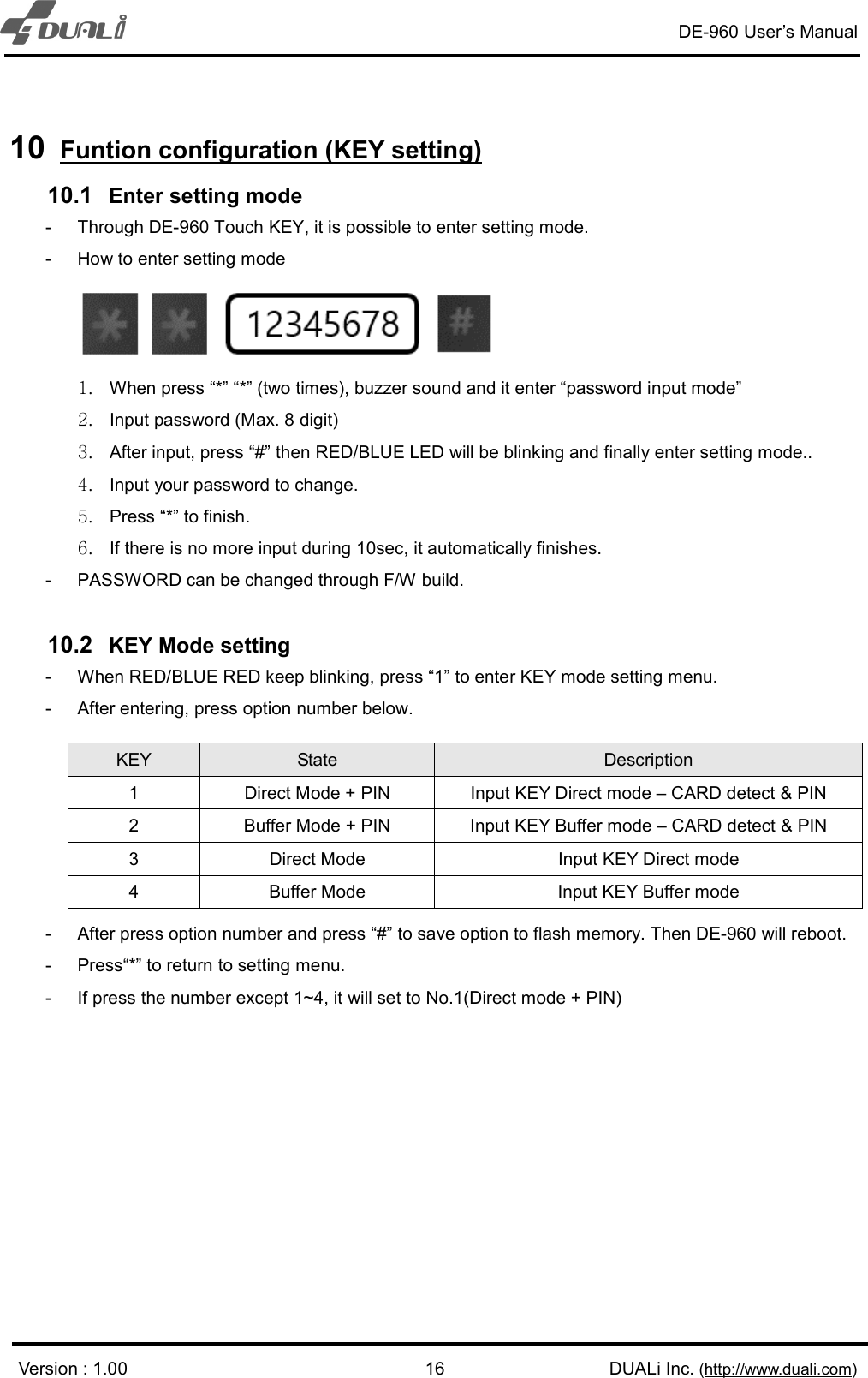
![DE-960 User’s Manual Version : 1.00 DUALi Inc. (http://www.duali.com) 107 Output format 7-1. Data format - Data format can be decided by setting. (Refer to chapter 8) <34bit> First Bit 1 : Even parity of bit 2 ~ bit 17 Data[1-32] : ID number(transmission data) Last Bit 34 : Odd parity of bit 18 ~ bit 33 <66bit> First Bit 1 : Even parity of bit 2 ~ bit 33(Data[1-32]) Data[1-64] : ID number(transmission data) FeliCa™ card – IDM data(8bytes) Mifare® card – Card serial number(4bytes)+0x00(4bytes) Last Bit 66 : Odd parity of bit 34 ~ bit 65(Data[33-64]) <32bit> Data[0-31] : ID number(transmission data) <64bit> Data[0-63] : FeliCa™ card – IDM data(8bytes) Mifare® card – Card serial number(4bytes)+0x00(4bytes)](https://usermanual.wiki/Duali/DE960/User-Guide-3307781-Page-10.png)
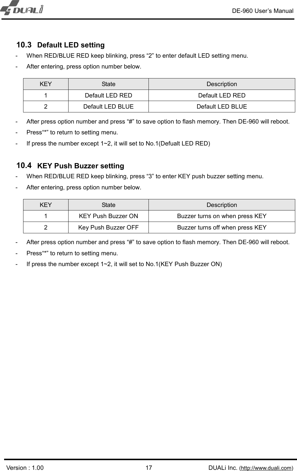
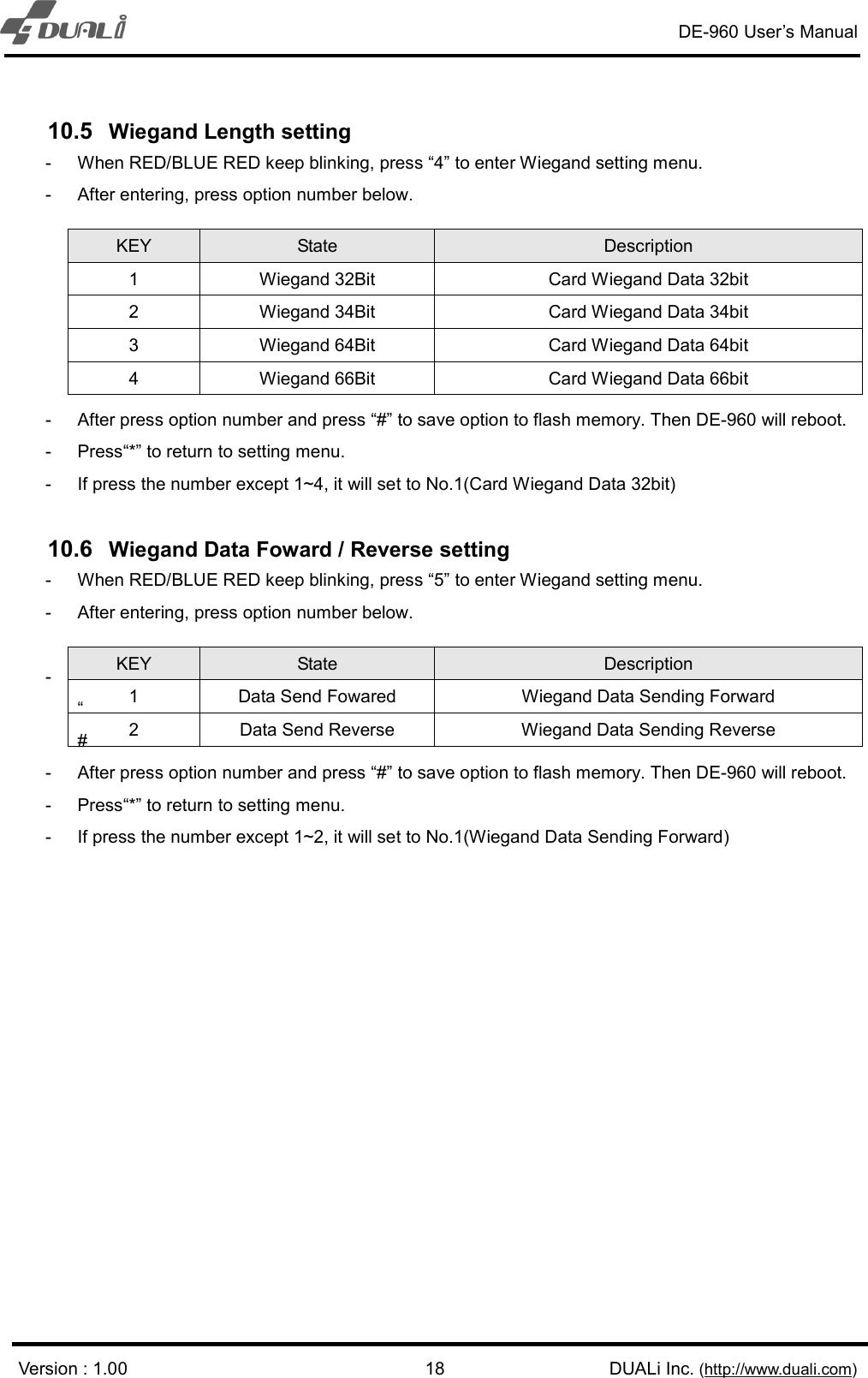
![DE-960 User’s Manual Version : 1.00 DUALi Inc. (http://www.duali.com) 129 Function configuration (Communication setting) 9.1 Wiegand option set Following is the communication frame for wiegand option setting. Since it is saved in flash memory after the first setting, the reader does not need to be set again. (9600bps, 8 data, no parity, 1 stop bit) STX LENH LENL CMD DATA LRC 0x02 0x00 0x02 0xE0 DATA[0] LENL ^ CMD ^ DATA[0] ( ^ : exclusive oring) 9.2 LED option set Following is the communication frame for LED color setting. Since it is saved in flash memory after the first setting, the reader does not need to be set again. (9600bps, 8 data, no parity, 1 stop bit) STX LENH LENL CMD DATA[0] LRC 0x02 0x00 0x02 0xE1 0- BLUE LED ON 1- RED LED ON LENL ^ CMD ^ DATA[0] DATA[0] State Description Bit7~4 RFU RFU Bit3 0 4byte ID(32 or 34bit) depend on parity setting(No.2) 1 8byte ID(64 or 66bit) depend on parity setting(No.2) Bit2 0 Parity Send(34 or 66bit) depend on ID bytes(No.1) 1 Parity Omit(32 or 64bit) depend on ID bytes(No.1) Bit1 0 Forward ID byte order 1 Reverse ID byte order Bit0 0 Not Read MIFARE card in Security Mode (Security Mode : SAM authentication for FeliCa, Reader enters security mode when SAM exists when boot.) 1 Read MIFARE card in Security Mode](https://usermanual.wiki/Duali/DE960/User-Guide-3307781-Page-12.png)
![DE-960 User’s Manual Version : 1.00 DUALi Inc. (http://www.duali.com) 139.3 Automatic Card Detection Disable Following is the communication frame for automatic card detection disable setting This command controls the automatic card detection function. It is used when controlling DE-960 from host device like PC. (9600bps, 8 data, no parity, 1 stop bit) STX LENH LENL CMD LRC 0x02 0x00 0x01 0xEF 0xEE 9.4 KEY Mode option set Following is the communication frame for Key mode setting. Since it is saved in flash memory after the first setting, the reader does not need to be set again. (9600bps, 8 data, no parity, 1 stop bit) STX LENH LENL CMD DATA LRC 0x02 0x00 0x02 0xE3 0x01 DATA[1] LENL ^ CMD ^ DATA[0] ( ^ : exclusive oring) 9.5 PASS Buffer Length option set Following is the PASS Buffer communication frame for setting. Since it is saved in flash memory after the first setting, the reader does not need to be set again. (9600bps, 8 data, no parity, 1 stop bit) STX LENH LENL CMD DATA LRC 0x02 0x00 0x02 0xE3 0x02 DATA[1] DATA[2] LENL ^ CMD ^ DATA[0] ( ^ : exclusive oring) DATA[0] State Description 0x00 Direct Mode + PIN Input KEY Direct mode – CARD detect & PIN 0x01 Buffer Mode + PIN Input KEY Buffer mode – CARD detect & PIN 0x02 Direct Mode Input KEY Direct mode 0x03 Buffer Mode Input KEY Buffer mode DATA[x] State Description DATA[1] MINIMUM Length Set password minimum length (Range: 1~11) DATA[2] MAXIMUM Length Set password maximum length (Range: DATA[1]~12)](https://usermanual.wiki/Duali/DE960/User-Guide-3307781-Page-13.png)
![DE-960 User’s Manual Version : 1.00 DUALi Inc. (http://www.duali.com) 149.6 KEY Timeout option set Following is the communication frame for key time out option setting. Since it is saved in flash memory after the first setting, the reader does not need to be set again. (9600bps, 8 data, no parity, 1 stop bit) STX LENH LENL CMD DATA LRC 0x02 0x00 0x02 0xE3 0x03 DATA[1] LENL ^ CMD ^ DATA[0] ( ^ : exclusive oring) 9.7 KEY Sensitive option set Following is the communication frame for Touch Key sensitive option setting. Since it is saved in flash memory after the first setting, the reader does not need to be set again. (9600bps, 8 data, no parity, 1 stop bit) STX LENH LENL CMD DATA LRC 0x02 0x00 0x02 0xE3 0x04 DATA[1] LENL ^ CMD ^ DATA[0] ( ^ : exclusive oring) 9.8 KEY Push Buzzer option set Following is the communication frame for Key push buzzer option setting. Since it is saved in flash memory after the first setting, the reader does not need to be set again. (9600bps, 8 data, no parity, 1 stop bit) STX LENH LENL CMD DATA LRC 0x02 0x00 0x02 0xE3 0x05 DATA[1] LENL ^ CMD ^ DATA[0] ( ^ : exclusive oring) DATA[1] State Description 0x01~0x0A Touch Key Timeout Touch Key timeout setting (Range: 0x01~0x0A) DATA[1] State Description 0x01~0x04 Touch Key Sensitive Touch KEY sensitive set (Lower value is more sensitive) DATA[1] State Description 0x00 BUZZER OFF Touch KEY, buzzer off 0x01 BUZZER ON Touch KEY, buzzer on](https://usermanual.wiki/Duali/DE960/User-Guide-3307781-Page-14.png)
![DE-960 User’s Manual Version : 1.00 DUALi Inc. (http://www.duali.com) 15 9.9 RF Scan option set Following is the communication frame for RF Scan setting. Since it is saved in flash memory after the first setting, the reader does not need to be set again (9600bps, 8 data, no parity, 1 stop bit) STX LENH LENL CMD DATA LRC 0x02 0x00 0x02 0xE3 0x06 DATA[1] LENL ^ CMD ^ DATA[0] ( ^ : exclusive oring) DATA[1] State Description Bit7 0 TYPE-A / MIFARE Scan Off 1 TYPE-A / MIFARE Scan ON Bit6 0 TYPE-B Scan Off 1 TYPE-B Scan ON Bit5 0 FELICA Scan Off 1 FELICA Scan ON Bit4 RFU RFU Bit3 0 15693 Scan Off 1 15693 Scan ON Bit2 ~ Bit0 RFU RFU](https://usermanual.wiki/Duali/DE960/User-Guide-3307781-Page-15.png)