Dust Networks ETERNA1 802.15.4 Wireless Mesh Mote User Manual
Dust Networks, Inc. 802.15.4 Wireless Mesh Mote Users Manual
UserManual.wiki
>
Dust Networks
>
ETERNA1 User Manual
Users Manual
Navigation menu
Upload a User Manual
Namespaces
Wiki Guide
HTML
PDF
Info
Views
User Manual
Discussion / Help
Navigation
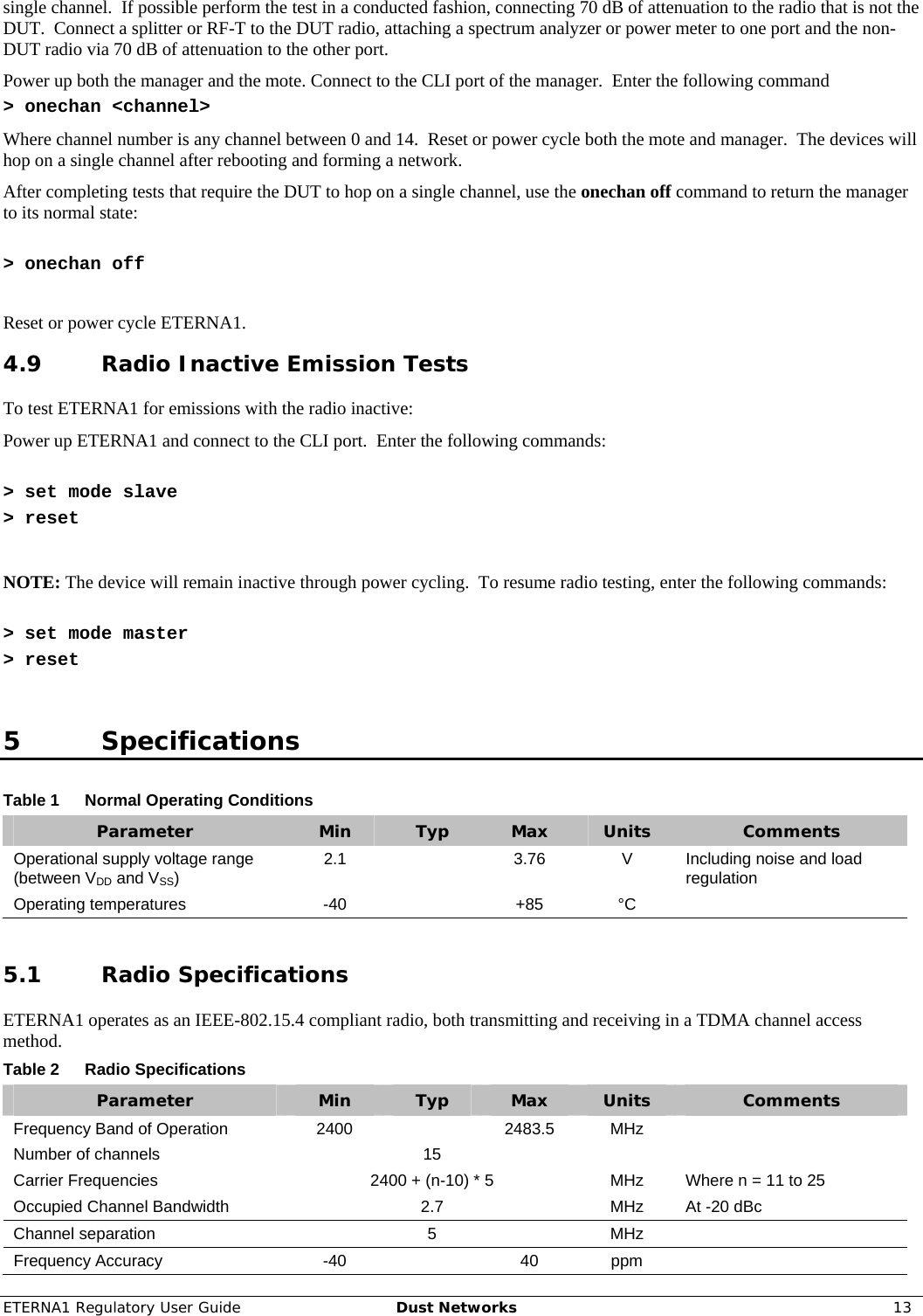
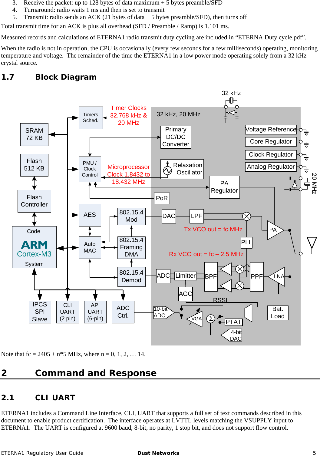
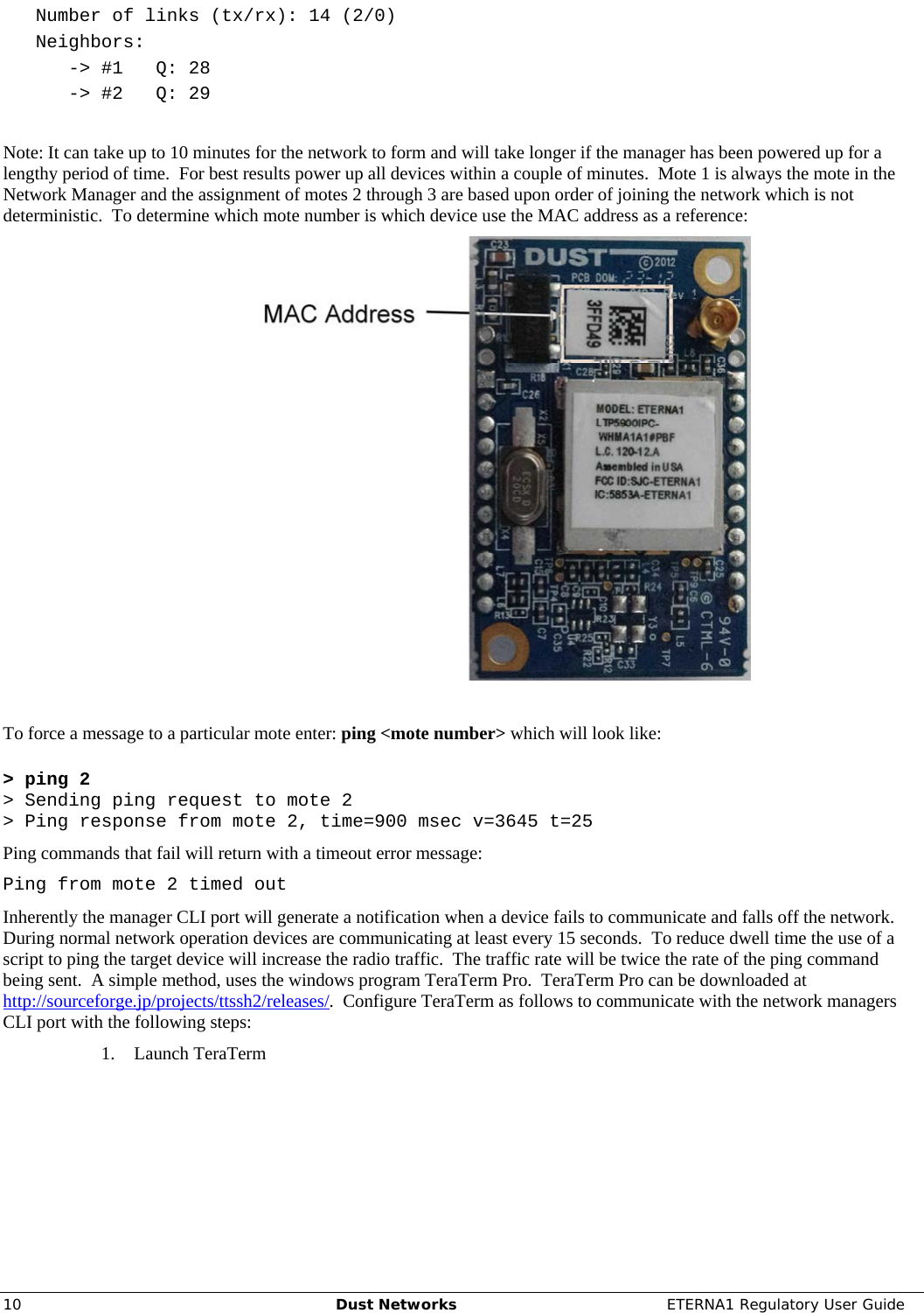
![4 Dust Networks ETERNA1 Regulatory User Guide 1 Introduction 1.1 Purpose This document is provided to OEMs for the installation of the ETERNA1 into a finished product. Provided the OEM’s usage of ETERNA1 is compliant with the requirements included in Section 6, the OEM is not required to complete radio certification of ETERNA1’s radio performance in FCC, IC and CE regulated geographies. In addition this manual provides the information necessary to perform certification of the ETERNA1 module for other geographies. 1.2 Scope This document is intended for those who are responsible for installing and testing the ETERNA1 module design for regulatory requirements. 1.3 References [1] IEEE Std 802.15.4-2006, Wireless Medium Access Control (MAC) and Physical Layer (PHY) Specifications for Low-Rate Wireless Personal Area Networks (LR-WPANs) 1.4 Definitions DUT Device Under Test Mote A node in a mesh network Low Channel The lowest frequency channel occupied by ETERNA1 is channel 0 centered at 2405 MHz. This channel corresponds to channel 11, as defined by [1]. Mid Channel The channel closest to the center of the 2.4 GHz ISM band occupied by ETERNA1 is channel 7, centered at 2440 MHz. This channel corresponds to channel 18, as defined by [1]. High Channel The highest frequency channel occupied by ETERNA1 is channel 14, centered at 2475 MHz. This channel corresponds to channel 25, as defined by [1]. 1.5 General Description ETERNA1 combines a microprocessor and a IEEE-802.15.4 radio with networking capabilities to provide a time synchronized, ultra low power network, designed to enable operation from battery sources for extended periods of time. The design is a PCB including “castellated” leads for access to the device and network, an SoC (includes radio and CPU), power supply filtering, and an MMCX connector to the antenna port or integral antenna. 1.6 Operational Description ETERNA1 provides a IEEE 802.15.4 compliant radios that modulate a DSSS OQPSK set of symbols at a chip rate of 2 Mcps. Dust radios operate on a TDMA time schedule that uses either 7.25 or 10 ms timeslots. A transmit timeslot consists of 5 stages: 1. Initialization: radio is prepared for transmit (transmitter is off) 2. Ramp: transmitter is ramped to peak power 3. Transmit: 128 bytes of data maximum + 5 bytes preamble/SFD 4. Turnaround: radio is set to receive 5. Receive: radio waits in receive for ACK, then turns off Total transmit time for a 128 byte packet plus all overhead (SFD / Preamble / Ramp) is 4.33ms. A receive timeslot consists of 5 stages: 1. Initialization: radio is prepared for receive 2. Check for start of packet – if no packet is received within a guard time the radio is disabled and no further action is taken](https://usermanual.wiki/Dust-Networks/ETERNA1/User-Guide-1866500-Page-4.png)
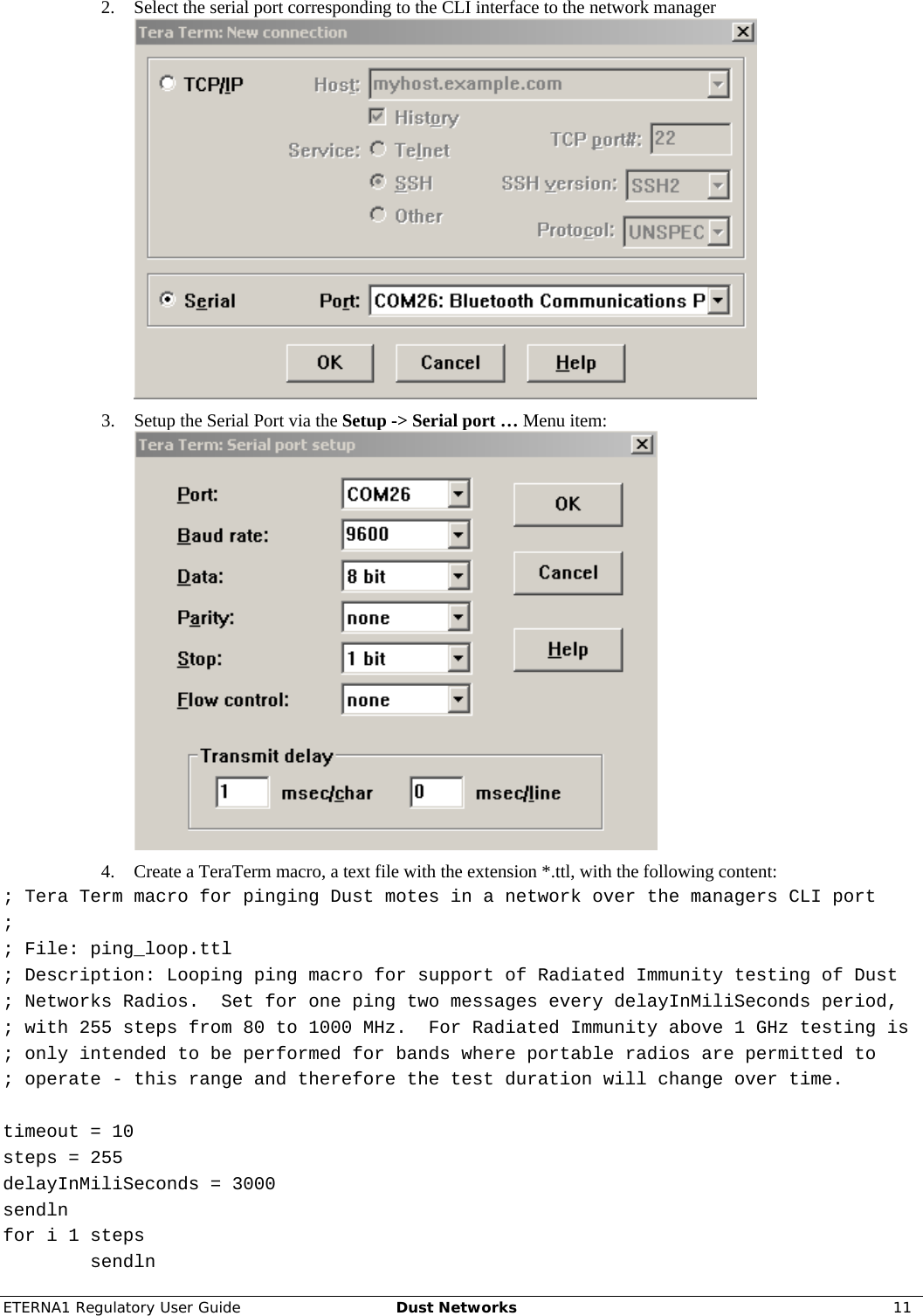
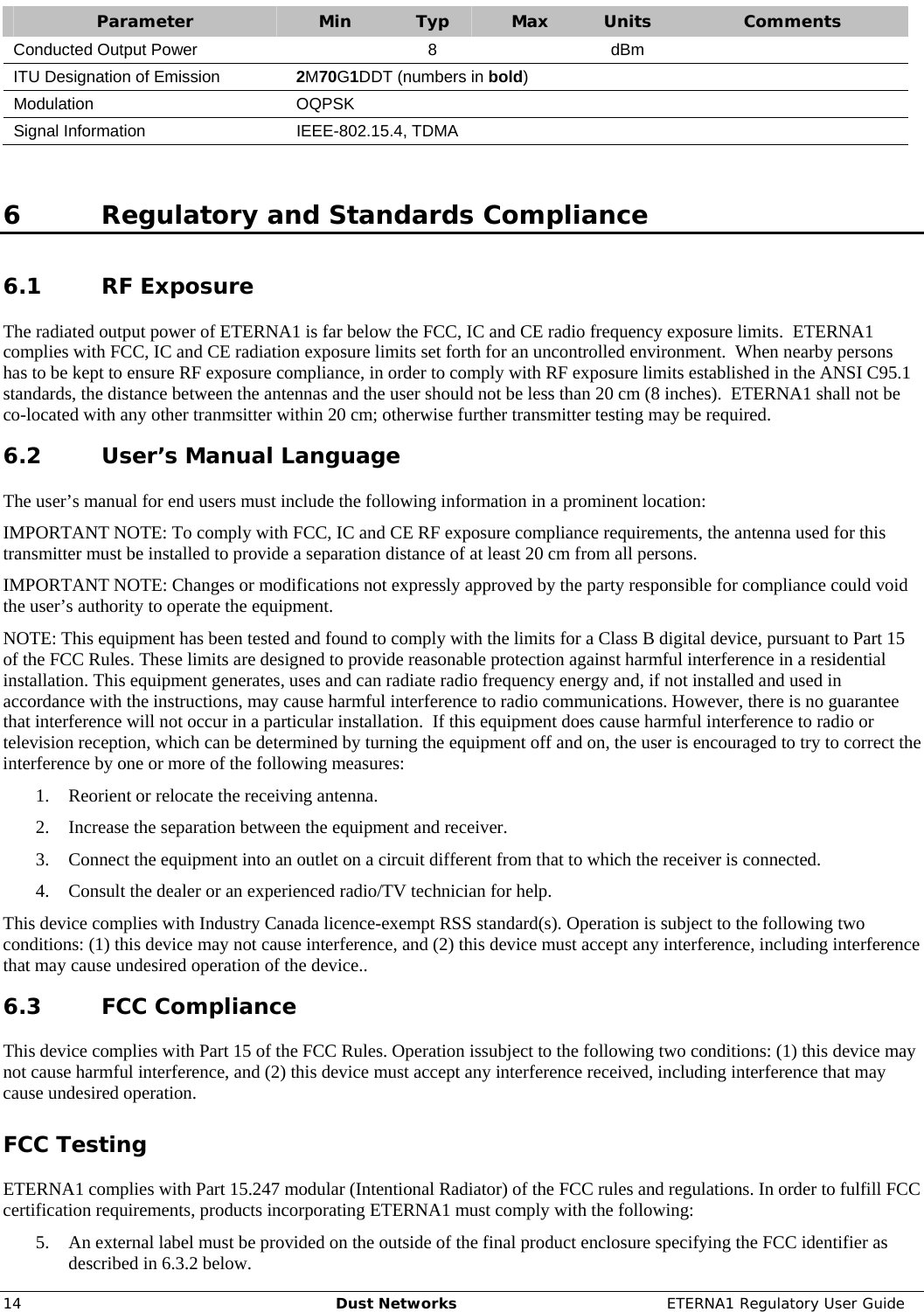
![12 Dust Networks ETERNA1 Regulatory User Guide sendln "ping 2" mpause delayInMiliSeconds next pause 5 sendln "#----- Macro Finish -----" end 5. Call the macro from the TeraTerm menu Control -> Macro and load the created macro file. This will create a series of Ping request and responses from the mote. 4.7 Minimum Frequency Occupation, Hopping Sequence and Tests Testing ETERNA1’s Minimum Frequency Occupation, Hopping Sequence is most easily measured by operating ETERNA1 in a self hoping mode. Power up both the manager and the mote and connect to the CLI port of each. Enter the following command > radiotest on Reset or power cycle both the mote and manager. The devices will hop between channels and transmit despite not being joined in a network. Start test: > radiotest tx <testType> <chanMask> <power> [<repeatCnt> {<pkLen> <delay>...}] <testType> is Type of transmission test to initiate: 'pk' = packets, 'cm' = continuous modulation, 'cw' - continuous wave. <chanMask> is a hex bitmap of channels to use with the LSB corresponding to channel 0 and the MSB corresponding to channel 15. Channel 15 in product is never used. E.g. 7fff results in operation on channels 0-14 and 0001 results in operations only on channel 0. <power> sets the radio output power, a value of 8 should be used for maximum power. The transmitter will transmit in a sequence of packets and gaps defined by a series of alternating <pkLen> and <delay> parameters. The <pkLen> parameter defines the packet length in terms of bytes and is limited to a range of 2 to 125 bytes. Note the protocol will append 8 bytes to the packet payload, so the actual transmitted length of bytes <pkLen> + 8, for a maximum of 133 bytes. The <delay> parameter defines the delay from the start of one packet to the next in μs. The <repeatCnt> parameter defines the number of times that the defined packet sequence will repeat. A <repeat> value of 0 results in the sequence repeating indefinitely. To demonstrate the maximum duty cycle of the system on the low channel using every slot issue the following command: > radiotest tx pk 0x0001 8 0 125 11483 24 6855 24 6833 24 2177 To demonstrate the maximum duty cycle of the system on the middle channel when every other slot is active, issue the following command: > radiotest tx pk 0x0080 8 0 125 11483 24 6855 24 6833 24 2177 To demonstrate the maximum duty cycle of the system on the high channel when every other slot is active, issue the following command: > radiotest tx pk 0x4000 8 0 125 11483 24 6855 24 6833 24 2177 After completing tests that require the DUT to hop outside of a network, use the radiotest off command to return the device to it’s normal state: > radiotest off Reset or power cycle ETERNA1. 4.8 Occupied Channel Bandwidth, Duty Cycle and Dwell Time Tests Testing ETERNA1’s Occupied Channel Bandwidth, Duty Cycle and Dwell Time, as per EN 300 328, is most easily measured by operating ETERNA1 in a network, in which both the network manager and the mote are configured to hop on a](https://usermanual.wiki/Dust-Networks/ETERNA1/User-Guide-1866500-Page-12.png)