DynaQuip Controls WPMS Monitoring Station User Manual
DynaQuip Controls Monitoring Station Users Manual
UserManual.wiki
>
DynaQuip Controls
>
WPMS User Manual
Users Manual
Navigation menu
Upload a User Manual
Namespaces
Wiki Guide
HTML
PDF
Info
Views
User Manual
Discussion / Help
Navigation
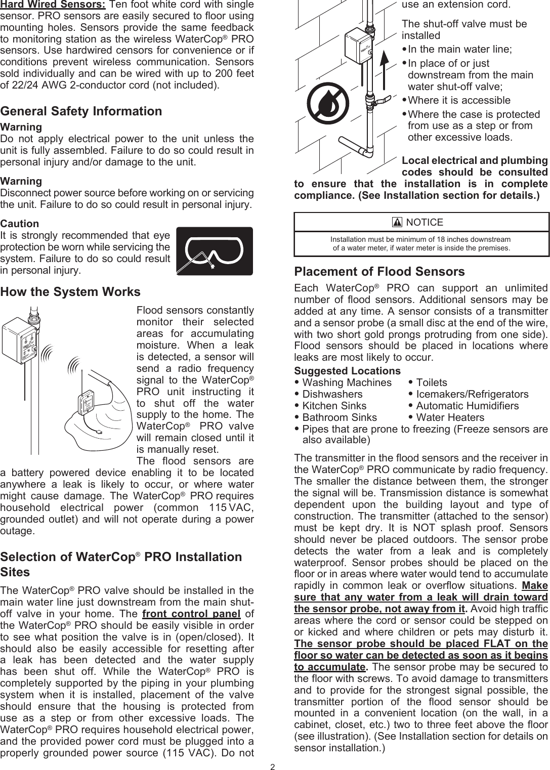
![SYSTEM QUICK REFERENCE SETTING AND STATUSReset Actuator to Factory Settings:Hold ‘MODE’ – Press and Release ‘OPEN’ – Release ‘MODE’TO ADD DEVICE:SENSORS: Press ‘MODE’ twice (Device Add) on WaterCop® PRO Actuator Press ‘CLOSE’ (Device #1 ID) Short probe on Sensor (Sensor #1 SHT) Remove short (Sensor #1 OK) Press ‘MODE’ Press ‘CLOSE’ (Sensor #2 ID) Repeat for all Sensors, When finished Press ‘Mode’ 2X to return to NORMALMONITORING STATION: Press ‘MODE’ twice (Device Add) on WaterCop® PRO Actuator Press ‘CLOSE’ [(Device # (next device number) ID] on WaterCop Actuator Press ‘CLOSE’ on Monitoring Station (This adds station and also closes valve). Press ‘OPEN’ on WaterCop® PRO Actuator to reopen valve and return to normal mode.REMOTE: Press “MODE’ twice (Device Add) Press ‘CLOSE’ (Device #1 ID) Press ‘CLOSE’ on REMOTE (Remote #1)TO REMOVE DEVICES: Press ‘MODE’ 3X (Device Remove) Press ‘CLOSE” to Scroll to device to be removed Press ‘OPEN’ to remove that device Press ‘MODE’ to return to NormalTO CHECK STATUS: Press ‘Mode’ Scroll using ‘CLOSE’ Press ‘MODE’ 3X to return to NormalTO TEST SIGNAL: HOLD ‘MODE’ Press and Release “CLOSE’ Press ‘OPEN’ (TX ACTIVE SIGNAL) Place sensor probe in water and read signal strength When finished, Hold ‘OPEN’ Press and Release ‘MODE’ to return to Normal5WaterCop® PRO wireless sensors are addressable. This means that the WaterCop® PRO valve can tell you operational status of each flood sensor. If you have many wireless sensors, this feature will quickly tell you where the leak is located or warn you if a sensor requires service (low batteries, lost connection). It is important that you introduce each wireless sensor to the WaterCop® PRO shutoff valve and document the sensor number on the sensor. Once placed in location you will also note this information on the Sensor Location Log (included). Once the wireless sensors are programmed you will be able to place them in desired locations to monitor your home or business for water intrusion.TO POWER AND PROGRAM WIRELESS SENSORSPowering Sensors Each wireless flood sensor is a battery operated (or AC adaptable) radio transmitter. The units are shipped without batteries. Two fresh “AA” lithium batteries or optional flood sensor AC adaptors are needed to power each unit. To install batteries, remove the battery cover located on the back of the sensor, and install batteries in accordance with the ( + and - ) placement guide. Reinstall back plate. It is recommended that you use batteries in addition to an AC adaptor to act as a power back up in the event of a power failure. Instructions on how to connect AC adaptors are included in this manual. It is important that you number each sensor with the included numbering stickers (shipped with the WaterCop® PRO motor) for easy identification while programming. If you do not have stickers, you may simply write numbers on the outside back cover of each sensor in permanent ink. The WaterCop® PRO system is capable of supporting as many as 46 wireless sensors. Additional wireless sensors (up to 46) can be added in the future by repeating the steps taken in this section. Please contact your local dealer or DynaQuip Controls to inquire about additional sensors.Once each sensor is powered and numbered, you are ready to begin addressing the sensors to the WaterCop® PRO motor.Programming Wireless SensorsPlug the WaterCop® PRO power supply into a nearby 115VAC outlet. Depending upon the position of the valve, the motor may initially turn the valve when first powered. BE EXTREMELY CAREFUL TO KEEP FINGERS AND OTHER ITEMS OUT OF THE VALVE. The display will read ‘WaterCop® NORMAL’ To add sensor #1, Press ‘MODE’ twice (Device Add will display on LCD)Press ‘CLOSE’ once (Device #1 ID= will display on LCD)Short probe on sensor by touching leads with metal. Do not wet sensor-it must be shorted. Sensor will beep and LCD will display Service status sensor #1 OK!](https://usermanual.wiki/DynaQuip-Controls/WPMS/User-Guide-1243602-Page-5.png)