Dynabook UPA3297WL 802.11a/b/g Mini-PCI Module User Manual MB22 User s Manual
Toshiba Corporation 802.11a/b/g Mini-PCI Module MB22 User s Manual
Dynabook >
Contents
User Manual
UUserser’’ss M Manualanual
PA32PA329797UU--1MPC1MPC
AR5001 Client Utility HelpAR5001 Client Utility HelpPA3297U-1MPC
Wireless LAN Card FeaturesWireless LAN Card Features ...................................................................................................3
Card SpecificationsCard Specifications...............................................................................................................4
IntroductionIntroduction ..............................................................................................................................7
System RequirementsSystem Requirements...........................................................................................................8
Package ContentsPackage Contents..................................................................................................................8
Profile ManagementProfile Management.................................................................................................................8
Add a New or Modify a Configuration ProfileAdd a New or Modify a Configuration Profile......................................................................9
Ad Hoc Mode Profile ConfigurationAd Hoc Mode Profile Configuration....................................................................................10
Access Point Mode Profile ConfigurationAccess Point Mode Profile Configuration ...........................................................................11
Remove a Configuration ProfileRemove a Configuration Profile..........................................................................................13
TCP/IP ConfiguratiTCP/IP Configurati onon.........................................................................................................13
Profile ManagementProfile Management............................................................................................................13
Zero ConfigurationZero Configuration..............................................................................................................14
Security TabSecurity Tab............................................................................................................................15
Define PreDefine Pre--Shared Encryption KeysShared Encryption Keys...................................................................................16
Check the Status Information or DiagnosticsCheck the Status Information or Diagnostics........................................................................17
Current StatusCurrent Status....................................................................................................................17
Driver Information ButtonDriver Information Button..................................................................................................18
DiagnosticsDiagnostics..........................................................................................................................18
Profile Management: Available APs and Ad Hoc Networks ListProfile Management: Available APs and Ad Hoc Networks List ...........................................19
Action MenuAction Menu............................................................................................................................21
Country Code SelectorCountry Code Selector ........................................................................................................21
Tray IconTray Icon .................................................................................................................................23
Display SettingsDisplay Settings......................................................................................................................24
Updating the NDIS DriverUpdating the NDIS Driver .....................................................................................................25
Information sheetInformation sheet ...................................................................................................................26

Wireless LAN Card Features
The Wireless LAN Card is a wireless network card that fits into a Mini-PCI TypeIII slot.
Wireless LAWireless LAN Card TypesN Card Types
The Wireless LAN Card is a wireless network card that complies with the IEEE 802.11
standard on wireless LANs (Revision A, B, G), Turbo Mode. Revision A and G supports data
rates up to 54 Mbit/s. Revision B supports data rates up to 11 Mbit/s. Turbo Mode supports
data rates up to 108 Mbit/s.
n Wi-Fi (Wireless Fidelity) certified by the Wi-Fi Alliance. This means that your Wireless
hardware will communicate with other vendors’ IEEE 802.11 compliant wireless LAN
product. The 'Wi-Fi CERTIFIED' logo is a certification mark of the Wi-Fi Alliance.
n Fully compatible with any other wireless LAN system based on Direct Sequence Spread
Spectrum (DSSS)/ Orthogonal Frequency Division Multiplexing (OFDM) radio
technology that complies with the “IEEE 802.11 standard on wireless LANs (Revision A
or B or G).
Wireless LAN CardsWireless LAN Cards
The Wireless LAN Card supports the following wireless LAN features:
n Automatic Transmit Rate Select mechanism in the transmit range of 54,48,36,24,18,12,
9 and 6 Mbit/s. (Revision A, G)
n Automatic Transmit Rate Select mechanism in the transmit range of 11, 5.5, 2 and 1
Mbit/s. (Revision B)
n Automatic Transmit Rate Select mechanism in the transmit range of 108,96,72,48,36,
24,18 and 12 Mbit/s. (Turbo Mode)
n Frequency Channel Selection (5GHz:Revision A / 2.4GHz:Revision B, G).
n Roaming over multiple channels.
n Card Power Management.
n Wired Equivalent Privacy (WEP) data encryption, based on 152bit encryption
algorithm.
n Advanced Encryption Standard (AES) data encryption, based on 256bit encryption
algorithm.

Card Specifications
Form Factor - Mini PCI TypeIII
Capability - IEEE 802.11 Standard for Wireless LANS
Wi-Fi (Wireless Fidelity) certified by the Wi-Fi Alliance.
Network Operating - Microsoft Windows® Networking
System
Media Access Protocol - CSMA/CA (Collision Avoidance) with Acknowledgment (ACK)
Data Rate - 54/48/36/24/18/12/9/6 Mb/s (Revision A, G)
- 11/5.5/2/1 Mb/s (Revision B)
- 108/96/72/48/36/24/18/12 Mb/s (Turbo Mode)
Radio CharacteristicsRadio Characteristics
Radio Characteristics of Wireless LAN Cards may vary according to:
n country/region where the product was purchased
n Type of product
Wireless communication is often subject to local radio regulations. Although Wireless LAN
Wireless networking products have been designed for operation in the license-free 2.4GHz
and 5GHz band, local radio regulations may impose a number of limitations to the use of
wireless communication equipment.
NOTE: NOTE: Refer to the flyer "Information to the User” for regulatory information that may
apply in your country/region.
R-F Frequency -Band 5GHz (5150-5850 MHz) (Revision A, Turbo Mode)
-Band2.4GHz (2400-2483.5 MHz) (Revision B, G, Turbo Mode)
Modulation Technique -DSSS-CCK, DSSS-DQPSK, DSSS-DBPSK (Revision B)
-OFDM-BPSK, OFDM-QPSK, OFDM-16QAM, OFDM-64QAM
(Revision A, G, Turbo Mode)
The range of the wireless signal is related to the Transmit Rate of the wireless
communication. Communications at lower Transmit range may travel larger distances.
n The range of your wireless devices can be affected when the antennas are placed near
metal surfaces and solid high-density materials.
n Range is also impacted due to “obstacles” in the signal path of the radio that may
either absorb or reflect the radio signal.

Supported Frequency SubSupported Frequency Sub-- bandsbands
Subject to the radio regulations that apply in your country, your Wireless LAN Card may support
a different set of 2.4GHz channels.
Consult your Authorized Wireless LAN or TOSHIBA Sales office for information about the radio
regulations that apply in your country/region.
Wireless IEEE 802.11 Channels Sets (Revision B, G)
Frequency Range
Channel ID
2400-2472 MHz
1 2412
2 2417
3 2422
4 2427
5 2432
6 2437
7 2442
8 2447
9 2452
10 2457* *1)
11 2462
12 2467 *2)
13 2472 *2)
14 2484 *3)
*1) Factory-set default channels
*2) Available Area: All approved regions except USA, Canada, and TAIWAN.
*3) Available Area: Japan 802.11b mode only
Wireless Channels Sets (Turbo Mode;2.4GHz)
Frequency Range 2400-2472 MHz Note
Channel ID
6 2437 US only *1
*1: Available Area: US (USA, CANADA) only

When installing Wireless LAN Cards, the channel configuration is managed as follows:
n For wireless clients that operate in a Wireless LAN Infrastructure, the Wireless LAN Card
will automatically start operation at the channel identified by the Wireless LAN Access Point,
When roaming between different access points the station can dynamically switch to
another channel if required.
n For Wireless LAN Cards installed in Wireless clients that operating in a peer-to-peer mode,
the card will use the default channel 10.
n In a Wireless LAN Access Point, the Wireless LAN card will use the factory-set default
channel (printed in bold), unless the LAN Administrator selected a different channel when
configuring the Wireless LAN Access Point device.
Wireless IEEE 802.11 Channels Sets (Revision A)
Frequency Range 5150-5850 MHz Note
Channel ID
36 5180 *1
40 5200 *1
44 5220 *1
48 5240 *1
52 5260 *1
56 5280 *1
60 5300 *1
64 5320 *1
149 5745 US only *2
153 5765 US only *2
157 5785 US only *2
161 5805 US only *2
*1: Refer to Table1 about the Europe area. USA and CANADA are available.
*2: Available Area: US (USA, CANADA) only

Table1: A table of allowed frequency ranges within Europe
Country/Region 5150-5250
MHz 5250-5350
MHz 5470-5725
MHz (*1) 5725-5850
MHz
Austria, Belgium, Italy,
Lichtenstein, Switzerland ラ ラ ラ
Denmark, Finland, France,
Germany, Ireland,
Netherlands , Portugal,
Sweden, UK
ラ
Luxemburg, Norway ラ ラ
Greece, Iceland, Spain ラ ラ ラ ラ
: allowed ラ: forbidden
*1) PA3297U-1MPC is not available in this frequency band.
Wireless Channels Sets (Turbo Mode;5GHz)
Frequency Range 5150-5850 MHz Note
Channel ID
42 5210 US only *1
50 5250 US only *1
58 5290 US only *1
152 5760 US only *1
160 5800 US only *1
*1: Available Area: US (USA, CANADA) only
Introduction
Atheros AR5001 Wireless Network Adapters are reference designs based on the Atheros
AR5001 chipsets. These reference designs support all IEEE 802.11a data rates (6 to 54
Mbps), 802.11b data rates (1 to 11 Mbps), and 802.11g (1 to 54 Mbps). In the Atheros Turbo
ModeTM, they support data rates up to 108 Mbps.
The Atheros Client Utility (ACU) is a user-mode utility designed to display information and
diagnostics pertaining to a selected Atheros NIC, as well as to allow users to edit and add
configuration profiles.

System Requirements
Laptop PC containing:
32-bit CardBus slot (or Desktop PC with PC Card-PCI adapter)
32 MB memory or greater
300 MHz processor or higher
Microsoft Windows 2000, Windows Millennium Edition,
Windows 98 Second Edition, Windows XP,
or Windows NT 4.0 (with Service Pack 6)
Package Contents
Make sure the following materials are available before beginning:
Atheros AR5001 Release v2.3
Atheros AR5001 Wireless Network Adapter, AR5BCB-00021B,
AR5BCB-00022A, AR5BMB-0022A, or Atheros customer station designs using
AR5001A or AR5001X chip sets
Profile Management
Conf igure the wireless network adapter (wireless card) from the Profile Management tab of
the Atheros Client Utility. From here, configuration profiles can be added, edited, or
removed, and you can also switch to a different profile.
The wireless network adapter works in either access point mode (infrastructure mode,
which uses an AP) or ad hoc mode (a group of stations participating in the wireless LAN).
To switch to a different configuration profileTo switch to a different configuration profile
Click on the profile name in the Profile list, then click the Activate button.
The Profile Management tab also includes a Scan Available Networks ... button that
displays Available APs and Ad Hoc Networks list, which describes the available APs and ad
hoc networks.
Highlight a network name and click the Activate button to connect an available network. If
no configuration profile exists for that network, the Network Configuration Settings opens
to the General tab. Fill in the network name and click OK to create the configuration
profile for that network.

Click the Refresh button to refresh the list of Available Access Points and Ad Hoc Networks.
To Connect to a Different Network:To Connect to a Different Network:
Highlight the network name in the list of Available APs and Ad Hoc Networks and click
the Activate button to connect to a different network.
Add a New or Modify a Configuration Profile
1. To add a new configuration profile, click New on the Profile Management tab. To
modify a configuration profile, select the configuration from the Profile list and click
the Modify button.
The Network Configuration Settings dialog box displays the General tab.
2. Edit the Network Configuration Settings:
Edit the General tab.
Edit the Security tab.
Edit the Advanced tab.
To configure a profile for ad hoc or access point (infrastructure) mode, edit the Network Type
field on the General tab.
General TabGeneral Tab
In the Atheros Client Utility, access the General tab by clicking New or Modify on the Profile
Management tab.
Edit the fields in the General tab to configure the configuration profile.
Make sure to also edit the Security and Advanced tabs.
Field Name Description
Profile Name Identifies the configuration profile. This name must be
unique. profile names are not case sensitive.
Network Names (SSIDs) The IEEE 802.11a wireless network name, (e.g., Atheros
802.11a Wireless Network). This field has a maximum limit
of 32 characters.
Up to three SSIDs can be configured (SSID1, SSID2, and
SSID3).
Advanced TabAdvanced Tab
In the Atheros Client Utility, access the Advanced tab by clicking New or Modify on the

Profile Management tab, then clicking the Advanced tab in the Network Configuration
Settings.
Edit the fields in the Advanced tab of the Network Configuration Settings to configure the
profile.
Make sure to also edit the General and Security tabs.
Field Name Description
Power Save Mode Specify maximum, normal, or off.
Network Type Specifies the network as either AP or Ad Hoc.
802.11b Preamble Specifies the preamble setting in 802.11b. The default
setting is Short & Long, which allows both short and long
headers in the 802.11b frames. Set to Long Only to override
allowing short frames.
Transmit Power Level Selects 100%, 50%, 25%, 12.5%, or Lowest transmit power.
Wireless Mode Specifies 5 GHz 54 Mbps, 5 GHz 108 Mbps, 2.4 GHz 11 Mbps,
or 2.4 GHz 54 Mbps operation in an access point network.
Wireless Mode when
Starting Ad Hoc
Network
Specifies 5GHz 54 Mbps, 5 GHz 108 Mbps, 2.4 GHz 11 Mbps,
or 2.4 GHz 54 Mbps to start an Ad Hoc network if no matching
network name is found after scanning all available modes.
Ad Hoc Mode Profile Configuration
To configure a profile in ad hoc mode, change the Network Type in the Profile Management's
Advanced tab. This table provides the Advanced tab field descriptions to configure a profile
for ad hoc mode:
Field Name Description
Network Type Ad Hoc.
802.11b Preamble Specifies the preamble setting in 802.11b. The default setting
is Short & Long, which allows both short and long headers in
the 802.11b frames. Set to Long Only to override allowing
short frames.
Transmit Power
Level
Selects 100%, 50%, 25%, 12.5%, or Lowest transmit power.
Wireless Mode Specifies 5 GHz 54 Mbps, 5 GHz 108 Mbps, 2.4 GHz 11 Mbps, or
2.4 GHz 54 Mbps operation in an access point network.
Wireless Mode when
Starting Ad Hoc
Specifies 5GHz 54 Mbps, 5 GHz 108 Mbps, 2.4 GHz 11 Mbps, or
2.4 GHz 54 Mbps to start an Ad Hoc network if no matching

Network network name is found after scanning all available modes.
If Ad Hoc 2.4 GHz is selected, select the channel to start the Ad
Hoc network on from the Channel drop-down menu.
Make sure to also edit the General and Security tabs.
Access Point Mode Profile Configuration
To configure a profile in Access Point (infrastructure) mode, change the Network Type in the
Advanced tab. This table provides the Advanced tab field descriptions to configure a profile
for access point mode:
Field Name Description
Power Save Mode The power management options:
OffOff The adapter receives full power from the PC.
NormalNormal The driver turns off power to the adapter for
short periods over briefly spaced time
intervals.
MaximumMaximum The driver turns off power to the adapter for
longer periods over more widely spaced time
intervals.
Network Type Access Point.
802.11b Preamble Specifies the preamble setting in 802.11b. The default setting
is Short & Long, which allows both short and long headers in
the 802.11b frames. Set to Long Only to override allowing
short frames.
Transmit Power
Level
Selects 100%, 50%, 25%, 12.5%, or Lowest transmit power.
Wireless Mode Specifies 5 GHz 54 Mbps or 5 GHz 108 Mbps operation in an
access point network.
Make sure to also edit the General and Security tabs.
Ad Hoc ModeAd Hoc Mode
In ad hoc mode, a wireless network adapter works within an independent basic service set
(IBSS), as illustrated here. All stations communicate directly with other stations without
using an access point (AP).
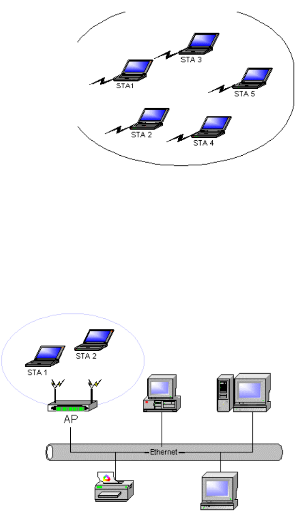
Ad Hoc ModeAd Hoc Mode
To connect to an ad hoc network, configure the profile for ad hoc mode.
Access Point (Infrastructure) ModeAccess Point (Infrastructure) Mode
In access point (infrastructure) mode, the wireless network adapter participates in a basic
service set (BSS) as a station, and communicates with the other stations through an AP, as
illustrated here.
Access Point (Infrastructure) Mode
To connect to an Access Point network, configure the profile for Access Point mode.

Remove a Configuration Profile
To remove a configuration profile, select the profile to remove from the list of
configuration profiles on the Profile Management tab.
2. Click the Remove button.
TCP/IP Configuration
Configure the TCP/IP Address for the network device after configuring the wireless network
adapter properties.
Open the Control Panel and click Network and Dial-up Connections.
Find the Local Area Connection associated with the wireless network adapter.
Right-click that connection, and click Properties.
Select Internet Protocol (TCP/IP) and click Properties.
Click the radio button Use the following IP address, then enter an IP address and
Subnet mask. Assigning an IP address and Subnet mask allows stations to
operate in access point mode (infrastructure mode) and to have Internet access.
Default gateway and DNS server information is also required.
IP configuration information (DHCP or assigned IP address, gateway and DNS
server IP addresses) is usually obtained from the corporate IT staff.
Click OK to finish.
Profile Management
Configure the wireless network adapter (wireless card) from the Profile Management tab of
the Atheros Client Utility. From here, configuration profiles can be added, edited, or
removed, and you can also switch to a different profile.
The wireless network adapter works in either access point mode (infrastructure mode,
which uses an AP) or ad hoc mode (a group of stations participating in the wireless LAN).
To switch to a different configuration profileTo switch to a different configuration profile
Click on the profile name in the Profile list, then click the Activate button.
The Profile Management tab also includes a Scan Available Networks ... button that
displays Available APs and Ad Hoc Networks list, which describes the available APs and ad
hoc networks.

Highlight a network name and click the Activate button to connect an available network. If
no configuration profile exists for that network, the Network Configuration Settings opens
to the General tab. Fill in the network name and click OK to create the configuration
profile for that network.
Click the Refresh button to refresh the list of Available Access Points and Ad Hoc Networks.
To Connect to a Different Network:To Connect to a Different Network:
Highlight the network name in the list of Available APs and Ad Hoc Networks and click
the Activate button to connect to a different network.
Zero Configuration
This section describes the operation of the Atheros Client Utility (ACU) and Windows XP
Wireless Configuration Service (WZCS).
Wireless Network ConfigurationWireless Network Configuration
The Windows WZCS is an NT service that manages the wireless connection in a largely
dynamic way. You need only identify and configure minimal connection information.
To set Zero Configuration on Windows XP, take the following steps:
1. In Windows XP, open the Wireless Network Configuration Properties dialog box.
2. Select the check box Use Windows to configure my wireless network settings
to set Zero Configuration.
When this check box is selected, Windows XP takes control of these settings for all
configuration profiles:
-SSID
-Security Keys
-Ad Hoc settings
The Zero Configuration settings override all configuration profiles, even when you select
other options. However, the ACU does still control the following settings when Zero
Configuration is set:
-Power settings
-Active/Passive scanning (where applicable)
-Transmit power
-Wireless band
-Short/Long preamble (11b)
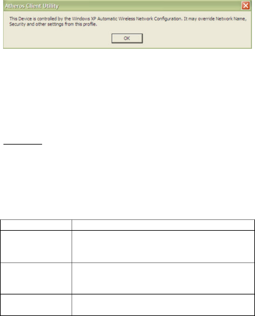
When Zero Configuration is in use, a pop-up message is displayed on the ACU when you
attempt to create or edit a configuration profile from the Station Configuration tab of the
ACU.
To turn Zero Configuration off on Windows XP, take the following steps:
1. In Windows XP, open the Wireless Network Configuration Properties dialog box.
2. Clear the check box Use Windows to configure my wireless network settings to
set Zero Configuration.
When this check box is cleared, all profile settings are controlled by the configuration profile,
which is set up from the Station Configuration tab of the ACU.
Security Tab
In the Atheros Client Utility, access the Security tab by clicking New or Modify on the
Profile Management tab. Click the Security tab in the Network Configuration Settings.
Edit the fields in the Security tab of the Network Configuration Settings to configure the
profile.
Make sure to also edit the General and Advanced tabs.
Field Name Description
Pre-Shared Keys Enables the use of pre-shared keys that are defined on both
the AP and the Station. Click on Define Pre-Shared Keys
button to enter pre-shared key information.
LEAP Enables the use of LEAP for dynamic security keys. Click on
Define User Information button to enter the LEAP User Name
and Password.
Externally Managed
802.1x Keys Sets up the station so that it uses externally provided 802.1x
authentication.

Disabled No security.
To define pre-shared encryption keys, click the Define Pre-Shared Keys button with
Pre-Shared Keys selected. Fill in the Define Pre-Shared Keys dialog.
Define Pre-Shared Encryption Keys
To define pre-shared encryption keys:
1. Click the Define Pre-Shared Keys button on the security tab.
2. Fill in the fields in the Security dialog box that opens:
Field Name Description
Key Entry Method Determines the entry method for an encryption key:
hexadecimal (0-9, A-F), or ASCII text (all keyboard characters).
Encryption Keys Selects the default encryption keys used (either Per-User or
Shared). Only allows the selection for a Per-User key, or a Shared
First, Second, Third, or Fourth key whose corresponding field has
been completed.
Per-User Key Defines the unique encryption key for network configuration
security. This field must be populated to enable security using a
unique key.
Click on the radio button to set the unique key as the default
encryption key.
Not used in ad hoc mode.
Shared Keys(1-4) Defines a set of shared encryption keys for network configuration
security. At least one Shared Key field must be populated to enable
security using a shared key.
Click on the radio button to set the key as the default encryption
key.
Key Length Defines the length for each encryption key. The options include:
64 bit (enter 10 digits)
128 bit (enter 26 digits)
152 bit (enter 32 digits)
As the Key Length is changed, the number of available characters
in the field automatically changes. If an already-entered key is too

long, the key is automatically truncated to fit. If the key length is
increased again, the field does not update to its previous value.
3. Click OK for the changes to take effect.
Encryption TypesEncryption Types
The wireless network adapter supports three encryption types: wired equivalent privacy
(WEP), advanced encryption security (AES), and Cisco Key Integrity Protocol (CKIP). While
WEP is universally supported and commonly used, AES provides a higher level of security
because frames encrypted with AES are more difficult to decipher without knowing the key.
To use AES, specify a unique key.
Note: AES is not supported in ad hoc mode, because ad hoc mode does not support unique
keys.
Encryption type is set on both the AP and the station. The station and AP negotiate and
attempt to use AES before exchanging data packets. By default, the station is set to auto
and attempts to use AES. It will only use WEP if the AP only supports or is configured for
WEP.
Check the Status Information or Diagnostics
The Atheros client utility includes a number of tools to display current diagnostics and
status information.
-Check current status
-Check driver information
-Check receive and transmit diagnostics
Current Status
The Current Status tab of the Atheros Client Utility contains general information about the
program and its operations. The Current Status tab does not require any configuration.
The following table describes the items found on the Current Status screen.
Screen Item Description
Profile Name The name of the current selected configuration profile.
Set up the configuration name on the General tab.
Network Type The type of network the station is connected to. The options
include:

-Access Point (Infrastructure)
-Ad Hoc
Configure the network type on the General tab.
Displays the wireless mode. The options include:
- 5 GHz 54 Mbps
- 5 GHz 108 Mbps
- 2.4 GHz 11 Mbps
Configure the wireless mode on the Advanced tab.
Current Channel Specifies the currently connected channel.
Link Status Shows whether the station is connected to the wireless network.
Encryption Type Displays the encryption type the driver is using. For example, the
modes can include:
- Off
- WEP
- AES
- CKIP
Configure the encryption type on the Security tab. For more
information, see Encryption Types.
IP Address The IP address of the station.
Click the Advanced button to see the advanced status diagnostics.
Driver Information Button
The Driver Information button contains general information about the network interface
card (the wireless network adapter) and the network driver interface specification (NDIS)
driver. Access the Driver Information from the Diagnostics tab.
The following table describes the items found on the Driver Information button.
Screen Item Description
Card Name The name of the wireless network adapter.
MAC Address The MAC address of the wireless network adapter.
Driver The driver name and path of the wireless network adapter driver.
Driver Version The version of the wireless network adapter driver.
Driver Date The creation date of the wireless network adapter driver
Diagnostics
The Diagnostics tab of the Atheros Client Utility provides buttons you can use to retrieve

statistics on receive and transmit. The Diagnostics tab does not require any configuration.
The Diagnostics tab lists the following receive and transmit diagnostics for frames received
by or transmitted by the wireless network adapter:
- Multicast frames transmitted and received
- Broadcast frames transmitted and received
- Unicast frames transmitted and received
- Total bytes transmitted and received
Click the Advanced Statistics button on the Diagnostics tab to also show receive and
transmit statistical information for the following receive and transmit diagnostics for
frames received by or transmitted to the wireless network adapter:
- Frames transmitted and received OK
- Transmitted frames retried
- Transmitted frames dropped
- Beacons received
- Frames received with errors
- Encryption errors
- Duplicate frames received
- Clear-to-send (CTS) frames received
- Authentication rejects: the number of access point authentication failures
received by the wireless network adapter
- Association rejects: the number of access point authentication rejects received by
the wireless network adapter
Click the Driver Information button on the Diagnostics tab for general information about
the network interface card (the wireless network adapter) and the network driver interface
specification (NDIS) driver.
Profile Management: Available APs and Ad Hoc Networks List
The Profile Management tab provides a Scan Available Networks button which contains
information about available access point and ad hoc networks.
Click on the Scan Available Networks button to access the Available Access Points and Ad
Hoc Networks dialog.
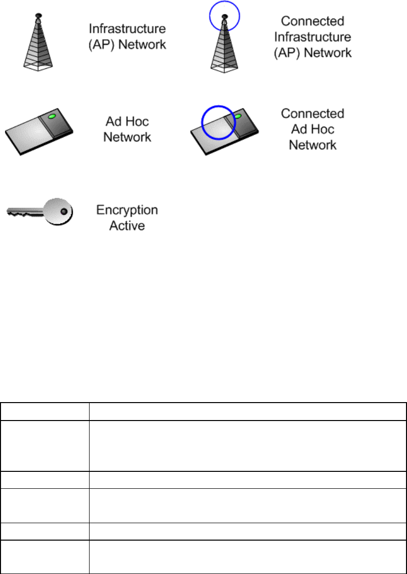
The Available Access Points and Ad Hoc Network dialog provides icons that specify the
operational state for that profile.
Available APs and Ad Hoc Networks Icons
Double-click on a network name to connect an available network. If no configuration profile
exists for that network, double-click on the network name to create a configuration profile
for that network.
The following table describes the columns found in the Available APs and Ad Hoc Networks
list.
Column Item Description
Network Name
(SSID)
The IEEE 802.11a wireless network name (service set
identification).
Configure the network name on the General tab.
Security Specifies the current state of security.
Signal Strength The received signal strength indicator. Displays the signal strength
in either dB or %, as well as the signal strength indicator.
Channel Specifies the current channel of operation.
Wireless Mode Displays the wireless mode. The options include 5 GHz 54 Mbps, 5
GHz 108 Mbps, or 2.4 GHz 11 Mbps.

Configure the wireless mode on the Advanced tab.
Click the Refresh button to refresh the list of Available Access Points and Ad Hoc Networks.
To Connect to a Different Network:
From the Profile Management tab, click on the Scan Available Networks button.
Highlight the network name in the list of Available APs and Ad Hoc Networks and click
the Activate button to connect to a different network.
Action Menu
Use the Action menu to access the Atheros Client Utility tools:
Enable/Disable Radio Enable or disable the RF Signal on all Atheros station
reference designs.
Country Select Open the Country Code Selector to set the regulatory domain
of the configuration profile.
This tool is only shown on cards that do not include the
World-Wide feature. These cards switch countries
automatically.
Enable/Disable Tray Icon Enable or disable the tray icon.
Exit Exit the Atheros Client Utility application.
Country Code Selector
The Country Code selector is a tool provided to allow users to select the country where they
are using the wireless network adapter. Access the Country Code Selector by choosing
Action > Country Select from the menu.
Note that this tool is not included for World-Wide cards, because these cards switch
countries automatically as needed.
To change the countryTo change the country
1.Choose the country to switch to from the Country pull-down menu in the Country
Code Selector.
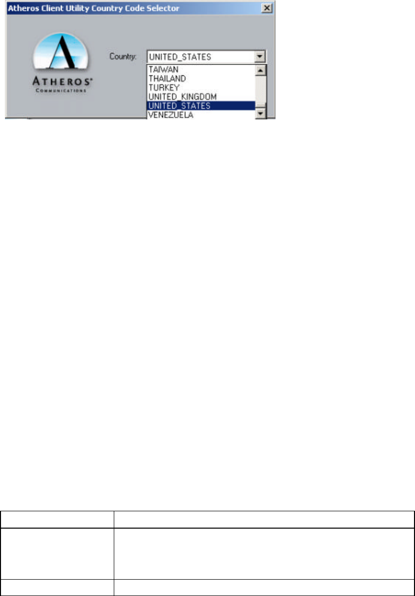
2. Click OK to continue.
Country selection takes effect immediately. View the advanced status information on the
Current Status tab to verify the selected country.
The wireless network adapter has EEPROM locations allocated to store country code
information. The selections represent three regulatory domains:
- FCC (USA and Canada)
- ETSI (Europe)
- MKK (Japan)
When the country code is changed, the NDIS driver scans only the legal frequency channels
allowed in those regulatory domains.
Note that the Country Select button is only available when the card is programmed to a
single country.
Advanced Status InformationAdvanced Status Information
Click the Advanced button on the Current Status tab of the Atheros Client Utility to see
advanced informati on about the program and its operations. The Current Status tab does
not require any configuration.
The following table describes the items found on the Advanced Status screen.
Screen Item Description
Country The country the card is set for.
Configure the country in the country code selector, accessible
from the Action menu.
Transmit Power Level The transmit power level shows the rate in dBm.
Network Name (SSID) The wireless network name.
Configure the network name on the General tab.
Power Save Mode The power management options. Power management is disabled
in ad hoc mode.
OffOff The adapter receives full power from the PC.
NormalNormal The driver turns off power to the adapter for
brief periods over briefly-spaced time intervals.
MaximumMaximum The driver turns off power to the adapter for
longer periods over more widely spaced time
intervals.
Configure the power save mode on the General tab.
Frequency The frequency the station is using.
Transmit Rate The transmit rate (Mbps) for the current connection for the
wireless driver.
Receive Rate The receive rate (Mbps) for the current connection for the driver.
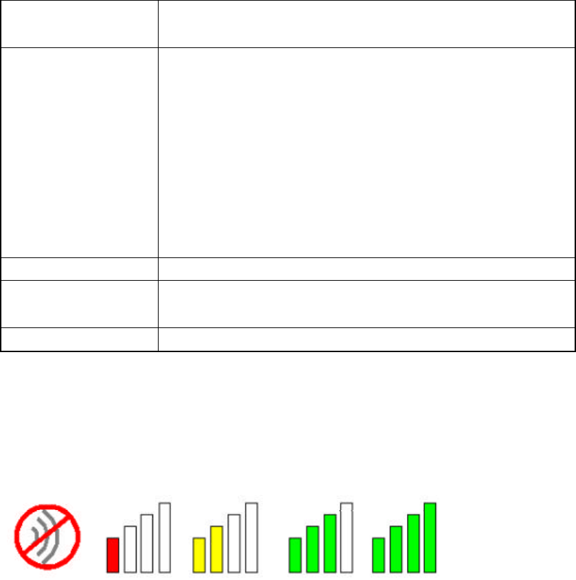
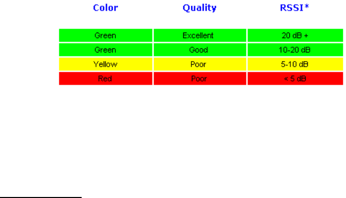
Tray Icon
The tray icon appears at the bottom of the screen, and shows the signal strength using
colors and the received signal strength indication (RSSI).
Tray IconsTray Icons
Hold the mouse cursor over the tray icon to display transmit and receive speed and the
current configuration profile name.
Right-click on the tray icon to:
Launch Station Utility Launch the Atheros Client Utility. Use the
Atheros Client Utility to configure the
profile or view status and statistics
information.
Atheros Client Utility Help Open the Atheros Client Utility online help.
Enable/disable radio Enable or disable the RF Signal.
Country Select Open the Country Code Selector to set the
regulatory domain of the configuration
profile.
Configuration Profile Click a configuration profile name to switch
to it. If no configuration profile exists for a
connection, add a profile first.
Exit Exit the Atheros Client Utility application.
The colors are defined as follows:
*Received signal strength indication RSSI.
Displayed in dB or percentage.
Enable or disable the tray icon in the Action menu.
Display Settings
To change the display settings, choose Options > Display Settings from the menu.
The display settings dialog box contains tools to set the:
Signal Strength Display Units Sets the units used when displaying signal
strength: percentage or dB.
Refresh Interval Sets the display refresh interval in seconds.
Data Display Sets the display to cumulative or relative:
-Relative displays the change (delta) in
statistical data since the last update.
-Cumulative displays statistical data
collected from the beginning of driver load.

Updating the NDIS Driver
The InstallShield process includes installing the NDIS drivers for the Atheros AR5001
Wireless Network Adapter (wireless card). If a new network adapter is installed, use the
following instructions to make sure the driver is updated for the new wireless network
adapter.
Windows XP and Windows 2000:Windows XP and Windows 2000:
With no existing Atheros NDIS driver installed, insert the wireless network adapter into a
32-bit CardBus slot. Update the NDIS driver:
1. Open the InstallShield Wizard (setup.exe).
2. Click Next to continue.
3. Click Yes to accept the License Agreement.
4. On the Setup Type page, choose Update Driver and Applications (recommended) or
Update Driver Only to update the NDIS driver. Click Next to continue.
5. Choose the destination location. Click Next to continue.
6. Choose whether to enable the Tray Icon. Click Next to continue.
7. Click Next to continue.
8. Click Finish when the InstallShield Wizard is complete.
9. After installing the network card, set up the configuration profiles.
Windows 98, Windows ME, and Windows NT:Windows 98, Windows ME, and Windows NT:
With no existing Atheros NDIS driver installed, insert the wireless network adapter into a
32-bit CardBus slot . Update the NDIS driver:
1. Wait for the New Hardware Wizard to display.
2. Click Next to continue.
3. Choose Search for a suitable driver for my device (recommended).
4. Click Next to continue.
5. Insert the Release CD into the CD-ROM drive.
6. Choose Specify a location under Optional search locations.
7. Click Next to continue.
8. Browse to the location where the NDIS driver is located. The default folder is
D: ¥ndis¥bin¥production¥ndis5, assuming D:¥ is the CD drive.
9. Click OK to continue.
10. After finding the Atheros driver installation file net5211.inf, click Next to continue.

11. The Atheros NDIS evaluation driver currently does not have a digital signature from
Microsoft, so Windows may display a warning message. Click Yes to proceed with driver
installation.
12. Click Finish to complete the driver installation.
13. After installing the network card, set up the configuration profiles.
Information sheet
Wireless Interoperability
The Atheros AR5001X+ Wireless Network Adapter products are designed to be interoperable
with any wireless LAN product that is based on Direct Sequence Spread Spectrum
(DSSS)/Orthogonal Frequency Division Multiplexing(OFDM) radio technology, and is compliant
to:
The IEEE 802.11 Standard on Wireless LANs(Revision A/B/G), as defined and approved
by the Institute of Electrical and Electronics Engineers.
The Wireless Fidelity(Wi-Fi) certification as defined by the Wi-Fi Alliance.
CAUTION
Bluetooth™ and WirelessLAN devices operate within the same radio frequency range and
may interfere with one another. If you use Bluetooth™ and WirelessLAN devices
simultaneously, you may occasionally experience a less than optimal network performance
or even lose your network connection.
If you should experience any such problem, immediately turn off either one of your
Bluetooth™ or WirelessLAN.
Please contact Toshiba PC product support on web site
http://www.toshiba-europe.com/computers/tnt/bluetooth.htm in Europe or
http://www.pc.support.global.toshiba.com in the United States for more information.
CAUTION
This device is restricted to indoor use due to its operation in the 5.15 to 5.85 GHz frequency
range.
Wireless LAN and your Health
Wireless LAN products, like other radio devices, emit radio frequency electromagnetic energy.
The level of energy emitted by Wireless LAN devices however is far much less than the
electromagnetic energy emitted by wireless devices like for example mobile phones.
Because Wireless LAN products operate within the guidelines found in radio frequency safety
standards and recommendations, TOSHIBA believes Wireless LAN is safe for use by consumers.
These standards and recommendations reflect the consensus of the scientific community and
result from deliberations of panels and committees of scientists who continually review and
interpret the extensive research literature.
In some situations or environments, the use of Wireless LAN may be restricted by the proprietor
of the building or responsible representatives of the organization. These situations may for
example include:
Using the Wireless LAN equipment on board of airplanes, or
In any other environment where the risk of interference to other devices or services is
perceived or identified as harmful.
If you are uncertain of the policy that applies on the use of wireless devices in a specific
organization or environment (e.g. airports), you are encouraged to ask for authorization to use
the Wireless LAN device prior to turning on the equipment.
Regulatory Information
The Atheros AR5001X+ Wireless Network Adapter must be installed and used in strict
accordance with the manufacturer’s instructions as described in the user documentation that
comes with the product. This device complies with the following radio frequency and safety
standards.
Canada – Industry Canada (IC)
This device complies with RSS 210 of Industry Canada.
Operation is subject to the following two conditions: (1) this device may not cause
interference, and (2) this device must accept any interference, including interference that
may cause undesired operation of this device.”
L ‘ utilisation de ce dispositif est autorisée seulement aux conditions suivantes : (1) il ne doit pas
produire de brouillage et (2) l’ utilisateur du dispositif doit étre prêt à accepter tout brouillage

radioélectrique reçu, même si ce brouillage est susceptible de compromettre le fonctionnement
du dispositif.
The term "IC" before the equipment certification number only signifies that the Industry
Canada technical specifications were met.
IC : 248H-DPA3297W
This device has been designed to operate with an antenna having a maximum gain of
4.8dB.Antenna having a higher gain is strictly prohibited per regulations of Industry
Canada. The required antenna impedance is 50 ohms.
To reduce potential radio interference to other users, the antenna type and its gain should
be so chosen that the equivalent isotropically radiated power (EIRP) is not more than that
required for successful communication.
To prevent radio interference to the licensed service, this device is intended to be operated
indoors and away from windows to provide maximum shielding. Equipment (or its transmit
antenna) that is installed outdoors is subject to licensing.
Pour empecher que cet appareil cause du brouillage au service faisant l'objet d'une licence, il
doit etre utilize a l'interieur et devrait etre place loin des fenetres afin de Fournier un ecram
de blindage maximal. Si le matriel (ou son antenne d'emission) est installe a l'exterieur, il
doit faire l'objet d'une licence.
Europe – EU Declaration of Conformity
This device complies with the essential requirements of the R&TTE Directive 1999/5/EC with
essential test suites as per standards:
For outdoor usage only channel 10 (2457 MHz) and 11 (2462 MHz) is allowed.
For private usage outside buildings across public grounds over less than 300m no special
registration with IBPT/BIPT is required. Registration to IBPT/BIPT is required for private
usage outside buildings across public grounds over more than 300m. An IBPT/BIPT license is
required for public usage outside building.
For registration and license please contact IBPT/BIPT.
Gebruik buiten gebouw alleen op kanalen 10 (2457 MHz) en 11 (2462 MHz). Voor privé-gebruik
buiten gebouw over publieke groud over afstand kleiner dan 300m geen registratie bij
BIPT/IBPT nodig; voor gebruik over afstand groter dan 300m is wel registratie bij BIPT/IBPT
nodig. Voor publiek gebruik buiten gebouwen is licentie van BIPT/IBPT verplicht. Voor
registratie of licentie kunt u contact opnemen met BIPT.
België/
Belgique:
L’utilisation en extérieur est autorisé sur le canal 10 (2457 MHz) et 11 (2462 MHz).
Dans le cas d’une utilisation privée, à l’extérieur d’un bâtiment, au-dessus d’un espace public,
aucun enregistrement n’est nécessaire pour une distance de moins de 300m. Pour une distance
supérieure à 300m un enregistrement auprès de I’IBPT est requise. Pour une utilisation
publique à I’extérieur de bâtiments, une licence de I’IBPT est requise. Pour les
enregistrements et licences, veuillez contacter I’IBPT.
License required for outdoor installations. Check with reseller for procedure to follow Deutschland: Anmeldung im Outdoor-Bereich notwendig, aber nicht genehmigungspflichtig.Bitte mit
Händler die Vorgehensweise abstimmen.
France: Restricted frequency band: only channels 10 and 11 (2457 MHz and 2462 MHz respectively)
may be used in France. License required for every installation, indoor and outdoor
installations. Please contact ART for procedure to follow.

Bande de fréquence restreinte : seuls les canaux 10 à 11 (2457 et 2462 MHz respectivement)
doivent être utilisés en France.
Toute utilisation, qu’elle soit intérieure ou extérieure, est soumise à autorisation. Vous pouvez
contacter I’Autorité de Régulation des Télécommuniations (http://www.art-telecom.fr) pour la
procédure à suivre.
License required for indoor use. Use with outdoor installations not allowed Italia: E’necessaria la concessione ministeriale anche per l’uso interno.
Verificare con i rivenditori la procedura da seguire. L’uso per installazione in esterni non e’
permessa.
License required for outdoor installations. Check with reseller for procedure to follow Nederland Licentie verplicht voor gebruik met buitenantennes. Neem contact op met verkoper voor juiste
procedure
Table: A table of allowed frequency ranges within Europe
Country/Region 5150-5250
MHz 5250-5350
MHz 5470-5725
MHz (*1) 5725-5850
MHz
Austria, Belgium, Italy,
Lichtenstein, Switzerland × × ×
Denmark, Finland, France,
Germany, Ireland,
Netherlands, Portugal,
Sweden, UK
×
Luxemburg, Norway × ×
Greece, Iceland, Spain × × × ×
: allowed ×: forbidden
*1) PA3297U-1MPC is not available in this frequency band.
USA-Federal Communications Commission (FCC)
This device complies with Part 15 of FCC Rules. Operation of the devices in a Wireless LAN
System is subject to the following two conditions:
This device may not cause harmful interference.
This device must accept any interference that may cause undesired operation.
TOSHIBA is not responsible for any radio or television interference caused by unauthorized
modification of the devices included with this Atheros AR5001X+ Wireless Network Adapter, or
the substitution or attachment of connecting cables and equipment other than specified by
TOSHIBA.
The correction of interference caused by such unauthorized modification, substitution or
attachment will be the responsibility of the user.
Caution: Exposure to Radio Frequency Radiation.
The Atheros AR5001X+ Wireless Network Adapter will be installed with one of three types of
antennas. The all of antenna types, when installed are located at the upper edge of the LCD
screen. For all antennas, the radiated output power of the Atheros AR5001X+ Wireless
Network Adapter is far below the FCC radio frequency exposure limits. Nevertheless, the
Atheros AR5001X+ Wireless Network Adapter shall be used in such a manner that the
potential for human contact during normal operation is minimized. In normal operating
configuration, the LCD in the upright position, the distance between the antenna and the user
should not be less than 20cm. The antenna(s) used for this transmitter must not be co-located
or operating in conjunction with any other antenna or transmitter. Antenna(s) used in
5.15-5.25GHz frequency band must be integral antenna which provide no access to the end
user.
Refer to the Regulatory Statements as identified in the documentation that comes
with those products for additional information. The installer of this radio equipment mus
t ensure that the antenna is located or pointed such that it does not emit RF
field in excess of Health Canada limits for the general population; consult Safety
Code 6, obtainable from Health Canadas website www.hc-sc.gc.ca/rpb.
Relevant transmitters include FCC IDs: CJ6UPA3297WL, CJ6UPA3232BT.
Caution: Radio Frequency Interference Requirements.
This device is restricted to indoor use due to its operation in the 5.15 to 5.25 GHz frequency
range. FCC requires this product to be used indoors for frequency range 5.15 to 5.25 GHz to
reduce the potential for harmful interference to co-channel Mobile Satellite systems.
High power radars are allocated as primary users of the 5.25 to 5.35 GHz and 5.65 to 5.85 GHz
bands. These radar stations can cause interference with and/or damage this device.
Taiwan
Article 14 Unless approved, for any model accredited low power radio frequency electric
machinery, any company, trader or user shall not change the frequency,
increase the power or change the features and functions of the original design.
Article 17 Any use of low power radio frequency electric machinery shall not affect the
aviation safety and interfere with legal communications. In event that any
interference is found, the use of such electric machinery shall be stopped
immediately, and reusing of such products can be resumed until no interference
occurs after improvement.
The legal communications mentioned in the above item refer to radio
communications operated in accordance with telecommunication laws and
regulations.
Low power radio frequency electric machinery shall resist against interference
from legal communications or from industrial, scientific and medical radio
emission electric machinery.
Using this equipment in Japan
In Japan, the frequency bandwidth of 2,4002,483.5MHz for second generation low-power
data communication systems such as this equipment overlaps that of mobile object
identification systems (premises radio station and specified low-power radio station).
1. Sticker
Please put the following sticker on devices incorporating this product.
2. Indication
The indication shown below appears on this equipment.
(1) 2.4this equipment uses a frequency of 2.4GHz.
(2) DSThis equipment uses DS-SS modulation
2.4DSOF4
(1) (2) (3)
(4)
In the frequency bandwidth of this equipment, industrial device,
scientific device, medical device like microwave oven, licensed
premises radio station and non-licensed specified low-
power radio
station for mobile object identification system (RF-
ID) that is used in
product line of factories,(Other Radio Stations)are used.
1 Please make sure before using this equipment that no Other Radio
Stations are used in the neighborhood.
2 In case that RF interference occurs to Other Radio Stations from this
equipment, please change promptly the frequency for use, place to
use, or stop emitting Radio.
3 Please contact TOSHIBA Direct PC
if you have a problem, such as
interference from this equipment to Other Radio Stations

OFThis equipment uses OFDM modulation.
(3) 4
The interference range of this equipment is less than 40m.
(4) This equipment uses a frequency bandwidth from 2,400MHz to
2,483.5MHz. It is possible to avoid the band of mobile object
identification systems.
3. TOSHIBA Direct PC
Monday – Friday : 10:00 – 17:00
Toll Free Tel : 0120-13-1100
Direct Dial : 03-3457-5916
Fax : 03-5444-9450
Device Authorization
This device obtains the Technical Regulation Conformity Certification and it belongs to the
device class of radio equipment of low-power data communication system radio station
stipulated in the Radio Law of Japan.
The Name of the radio equipment: PA3297U-1MPC(1)
TELECOM ENGINEERING CENTER
Approval Number : 03NYDA****, 03WYBA****
The following restrictions apply:
Do not disassemble or modify the device.
Do not install the embedded wireless module into other device.
Trademark
Bluetooth is a trademark owned by its proprietor and used by TOSHIBA under license.