Dynabook UPA3503WL PCI Express 802.11 a/b/g transceiver User Manual Canary UserManual
Toshiba Corporation PCI Express 802.11 a/b/g transceiver Canary UserManual
UserManual.wiki
>
Dynabook
>
UPA3503WL User Manual
>
TECRA M7 User Manual
Contents
1.
User Manual
2.
Manual PortM400
3.
TECRA M7 User Manual
4.
PA3503U manual addendum
5.
Wireless WAN Guide
6.
Revised TecraM7 Manual 1
7.
Revised TecraM7 Manual 2
TECRA M7 User Manual
Navigation menu
Upload a User Manual
Namespaces
Wiki Guide
HTML
PDF
Info
Views
User Manual
Discussion / Help
Navigation

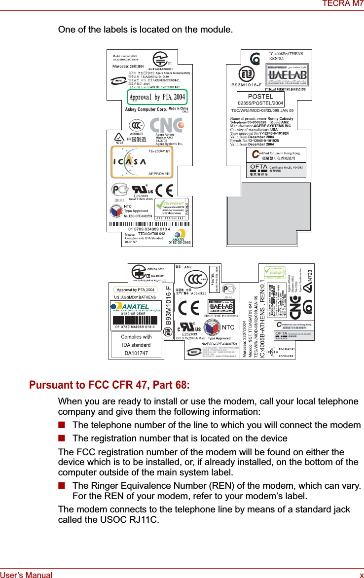
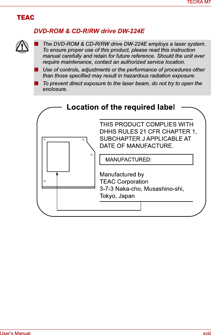
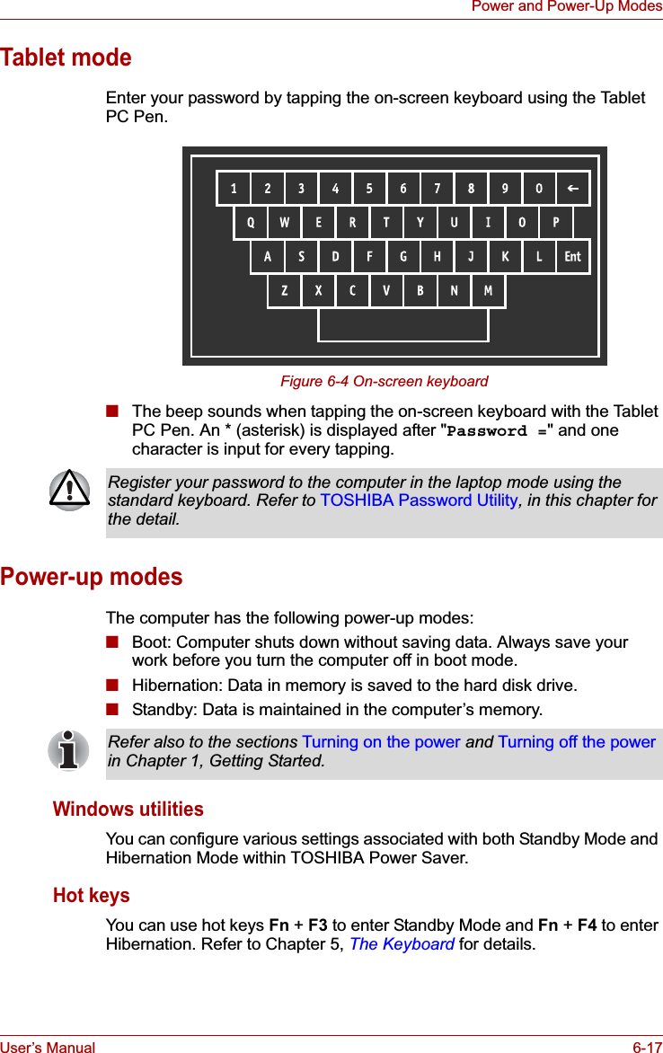
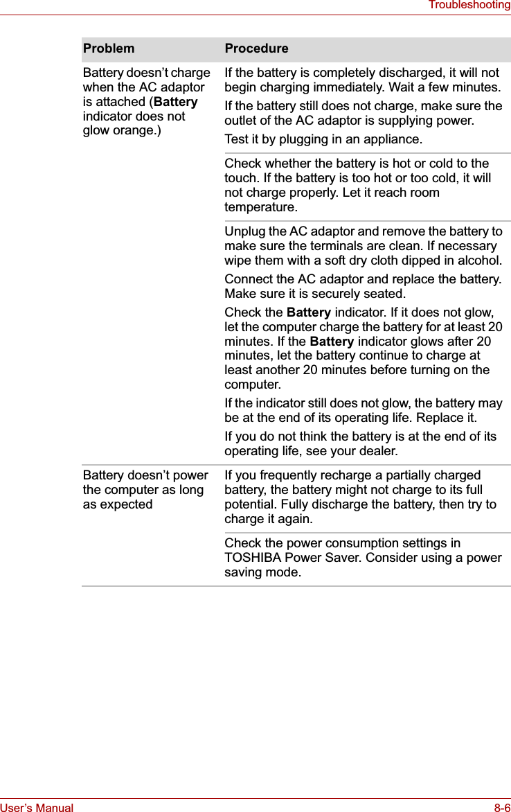
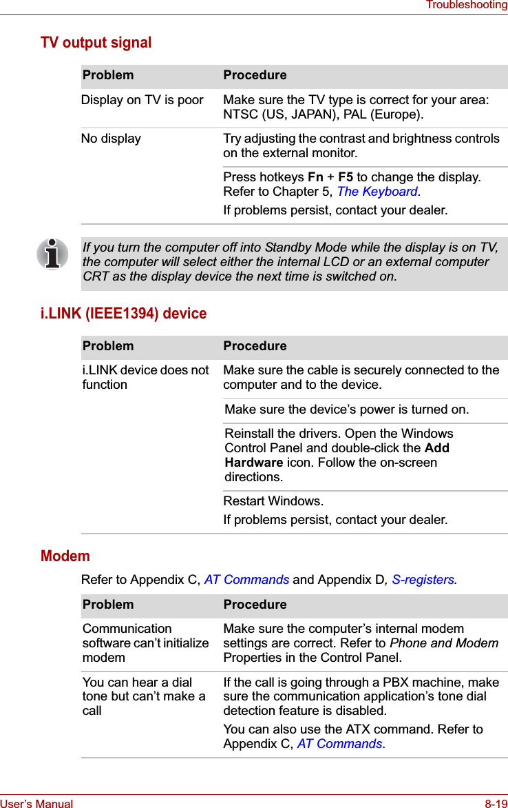
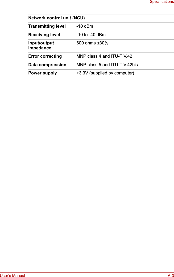
![User’s Manual viiiTECRA M7EU Declaration of ConformityTOSHIBA declares, that the product: PTM70*/PTM71* conforms to the following Standards:This product is carrying the CE-Mark in accordance with the related European Directives. Responsible for CE-Marking is TOSHIBA Europe Gmblt, Hammfelddamm 8, 41460 Neuss, Germany.VCCI Class B InformationModem warning noticeConformity StatementThe equipment has been approved to [Commission Decision "CTR21"] for pan-European single terminal connection to the Public Switched Telephone Network (PSTN).However, due to differences between the individual PSTNs provided in different countries/regions the approval does not, of itself, give an unconditional assurance of successful operation on every PSTN network termination point.In the event of problems, you should contact your equipment supplier in the first instance.Supplementary Information: “The product complies with the requirements of the Low Voltage Directive 73/23/EEC, the EMC Directive 89/336/EEC and/or the R&TTE Directive 1999/5/EC.”](https://usermanual.wiki/Dynabook/UPA3503WL.TECRA-M7-User-Manual/User-Guide-693494-Page-8.png)
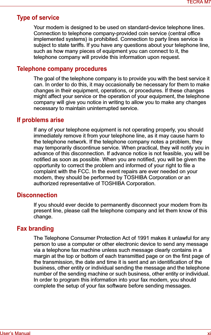
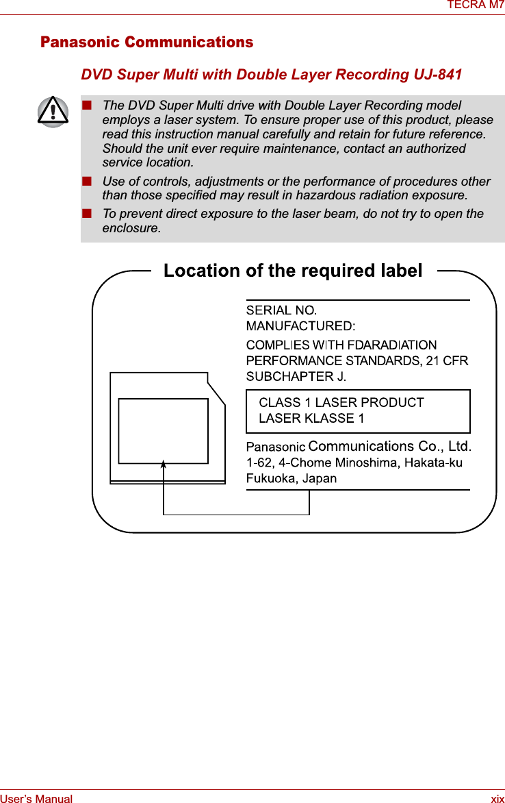
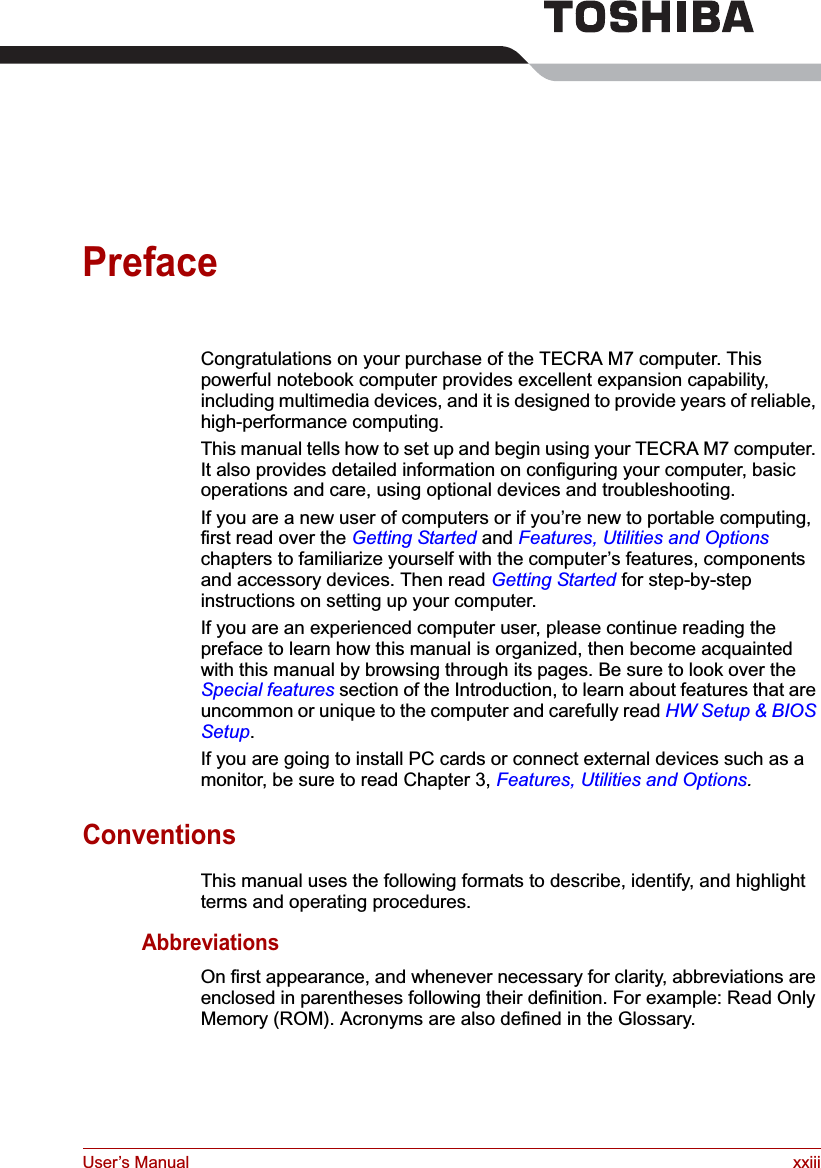
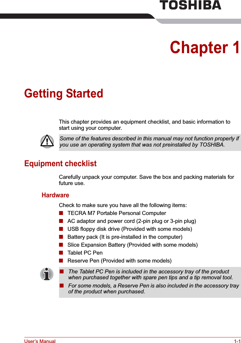
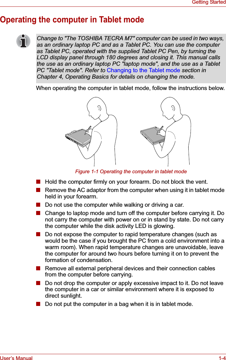
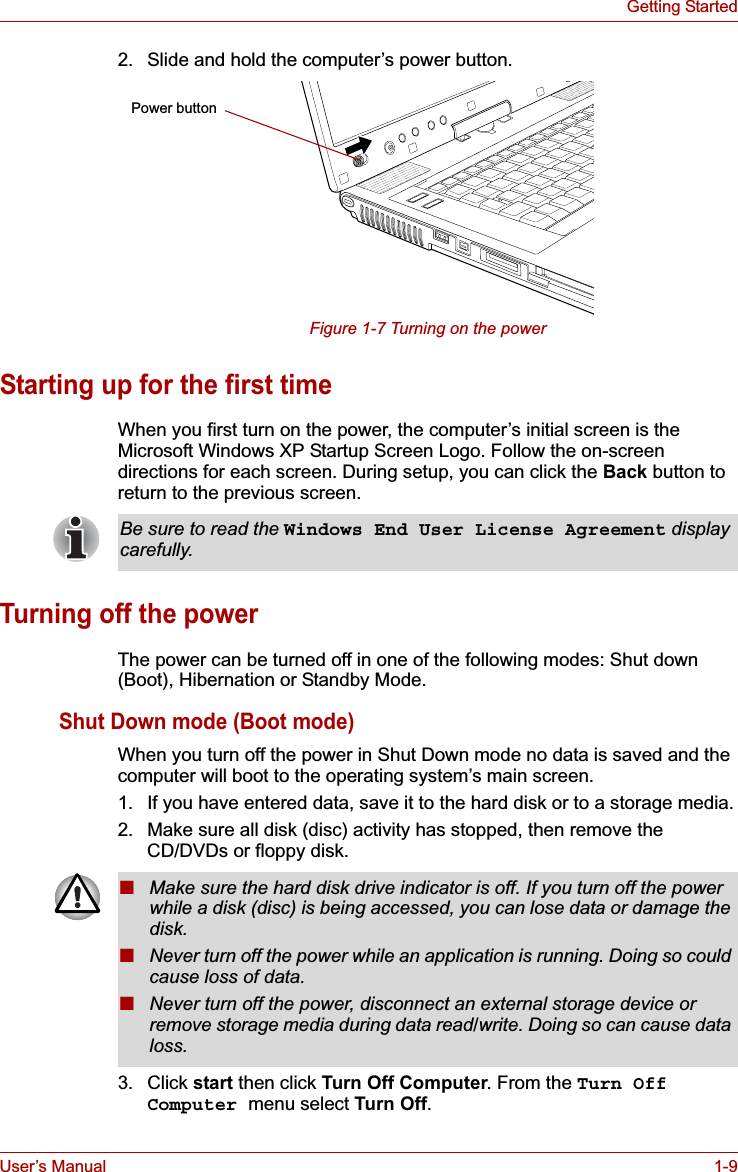
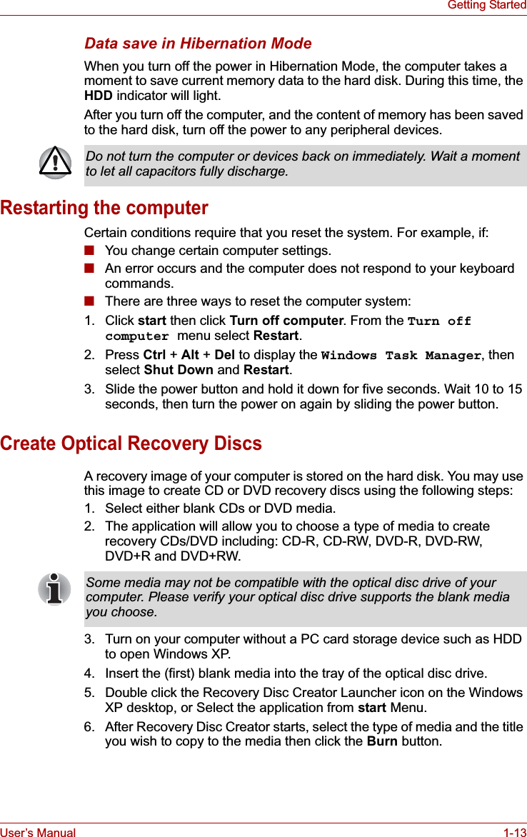
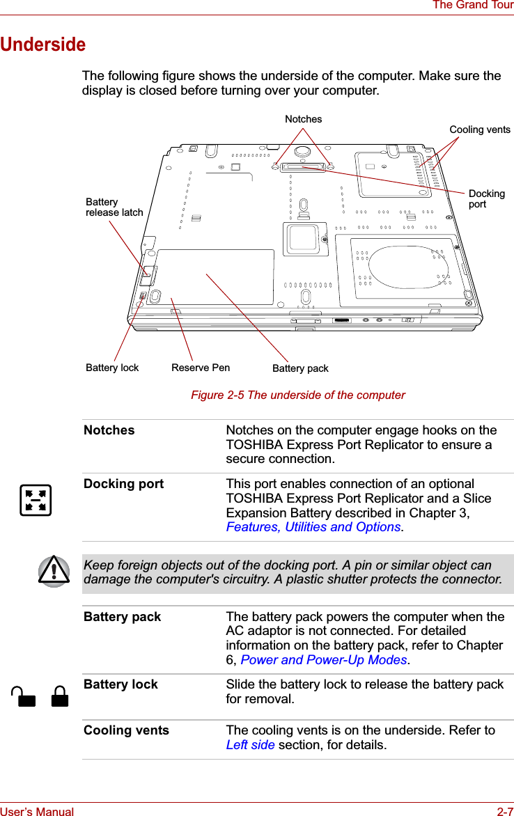
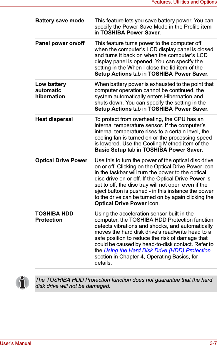

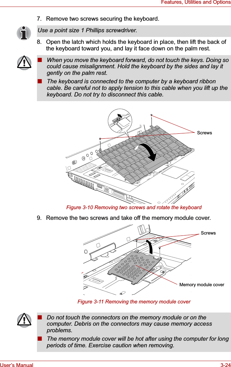
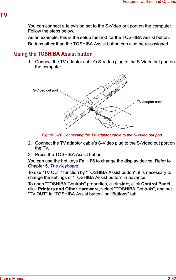
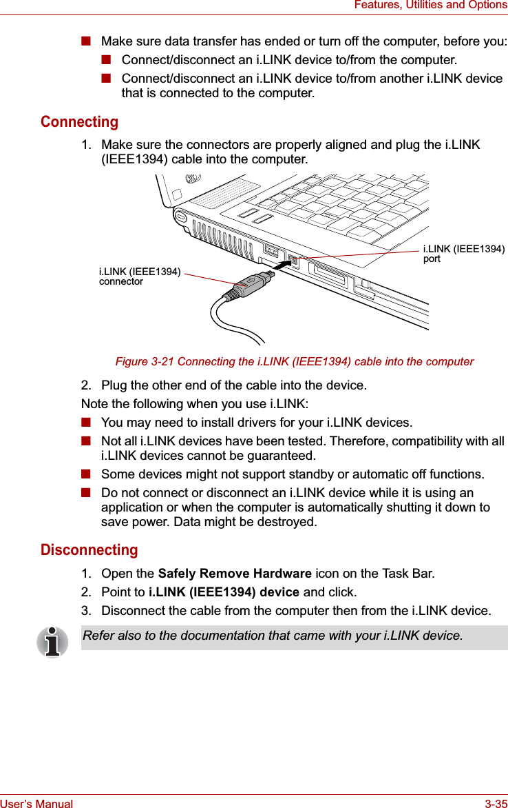
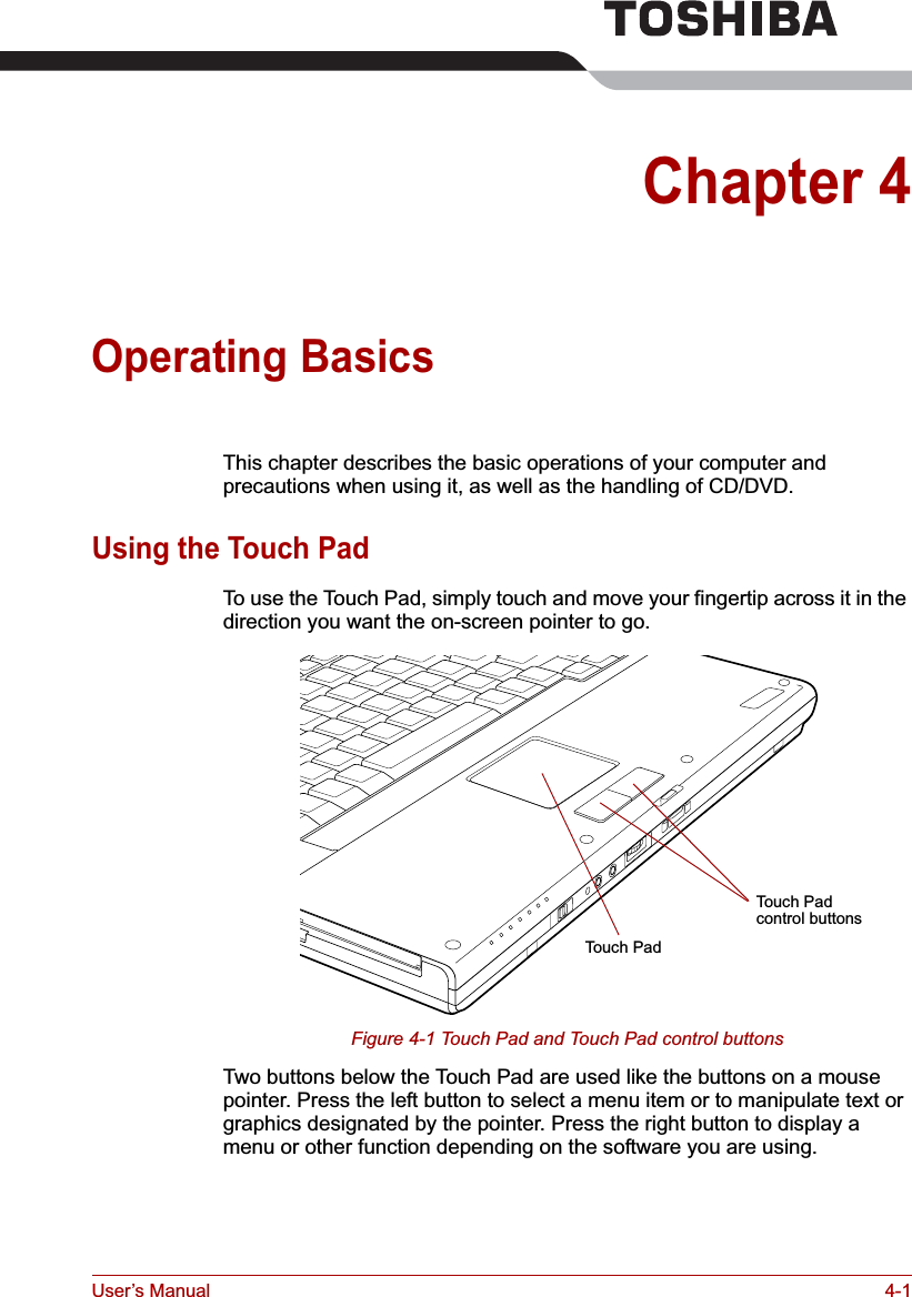
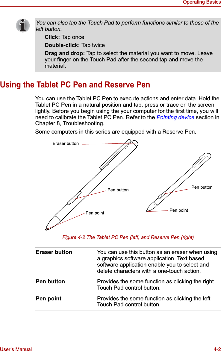
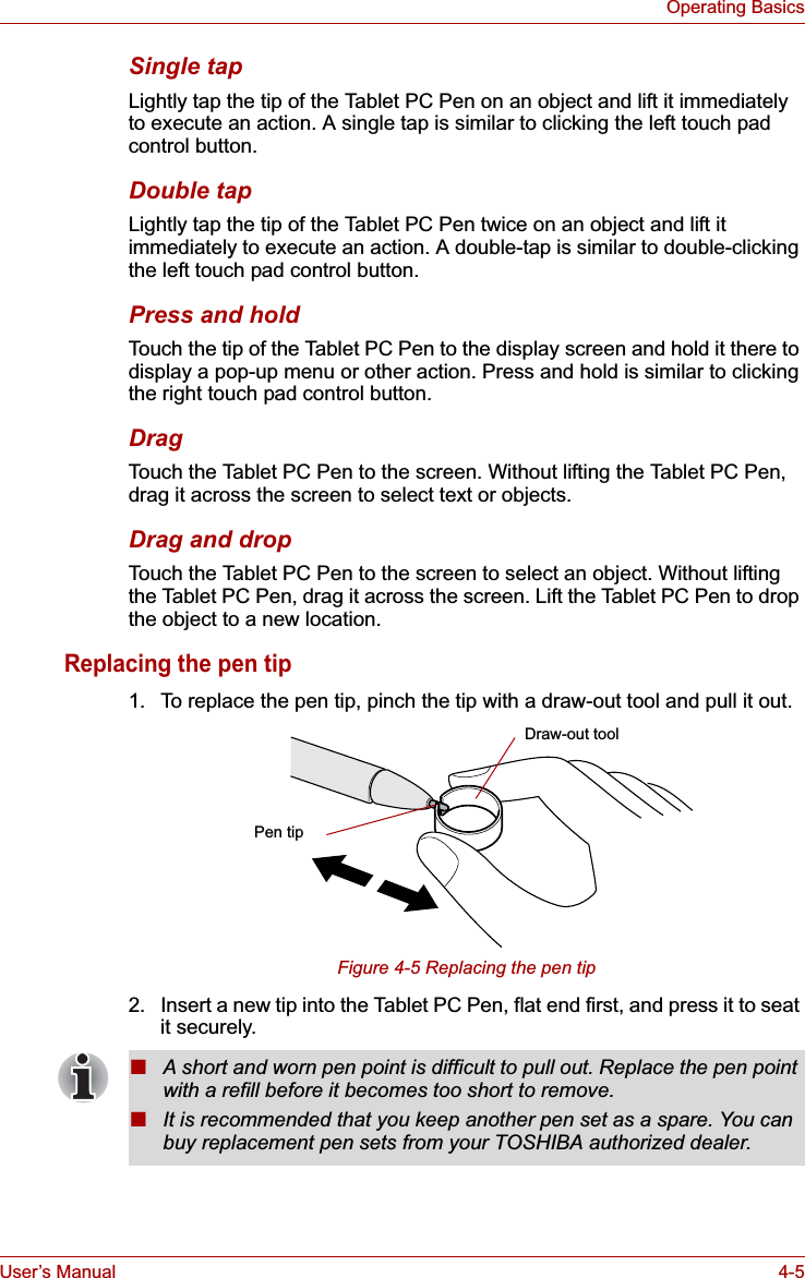
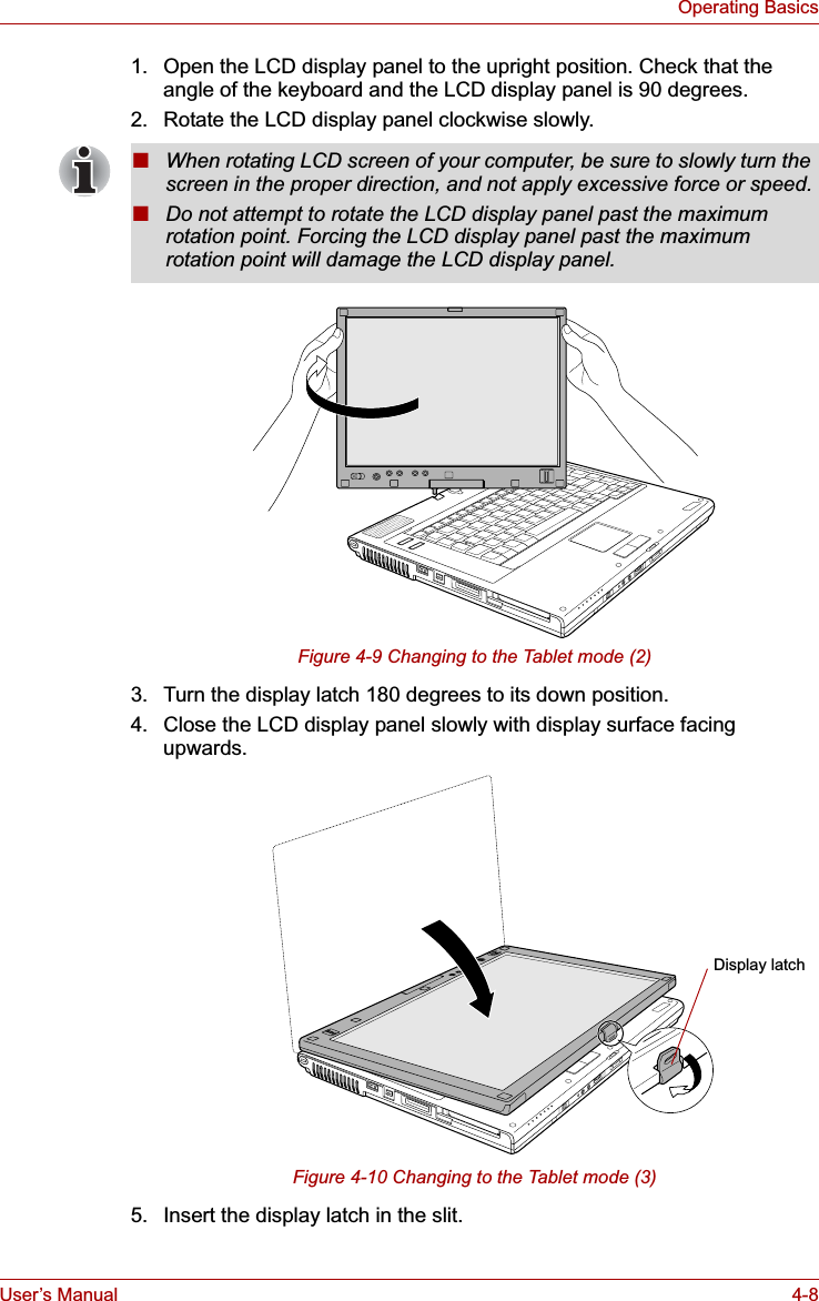
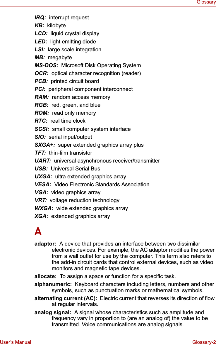
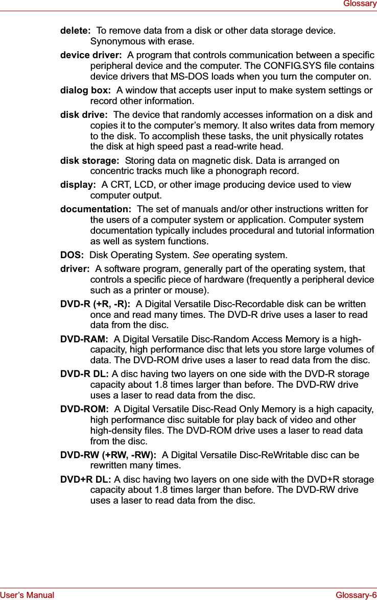
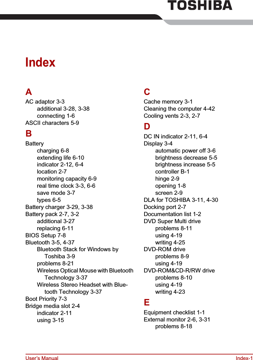
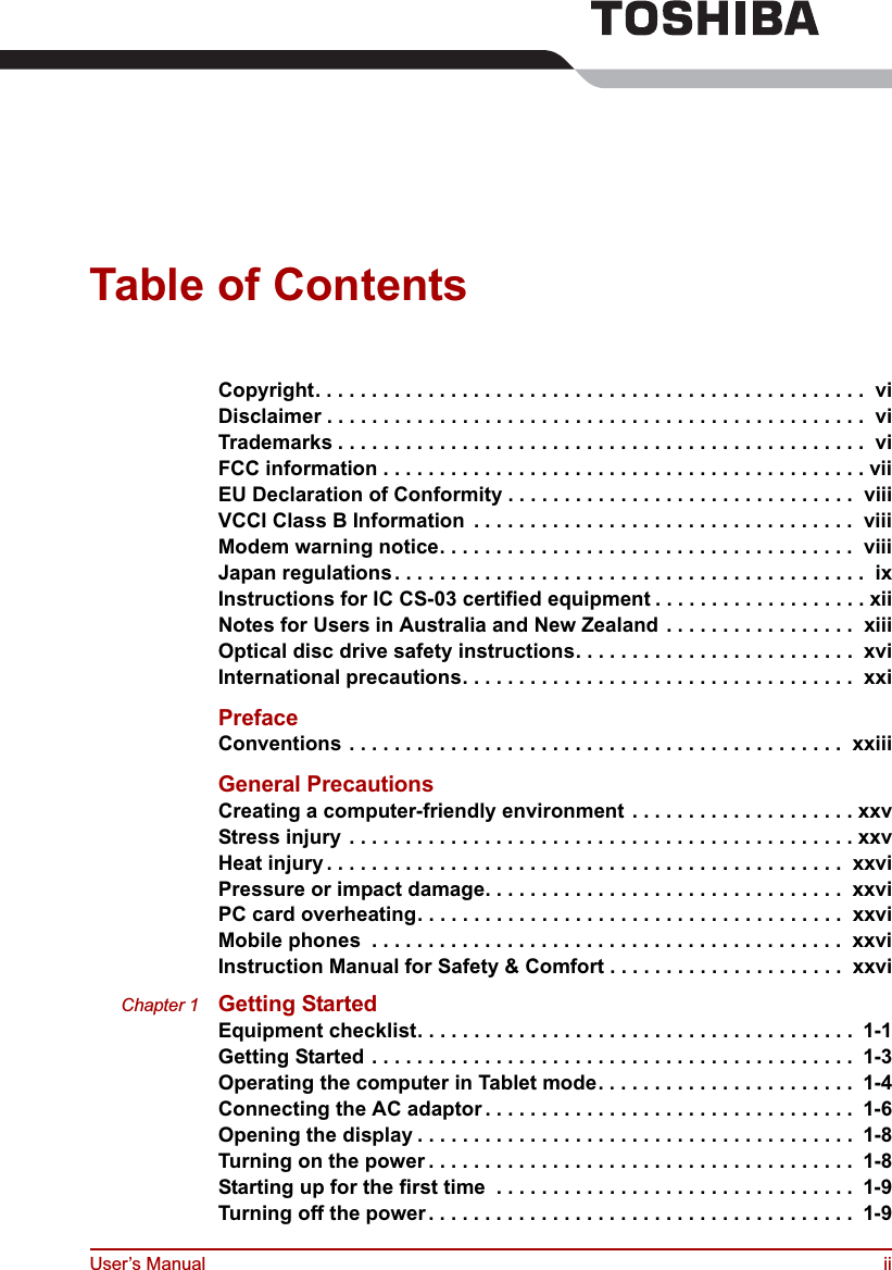
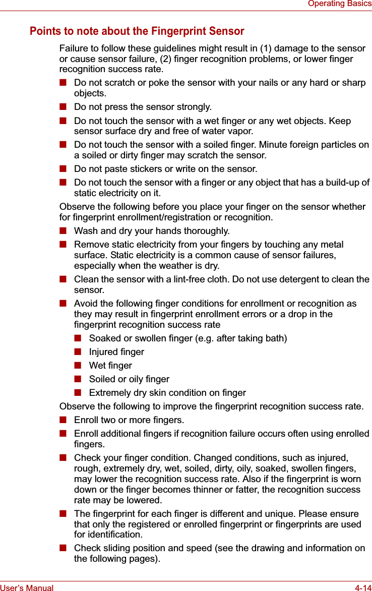
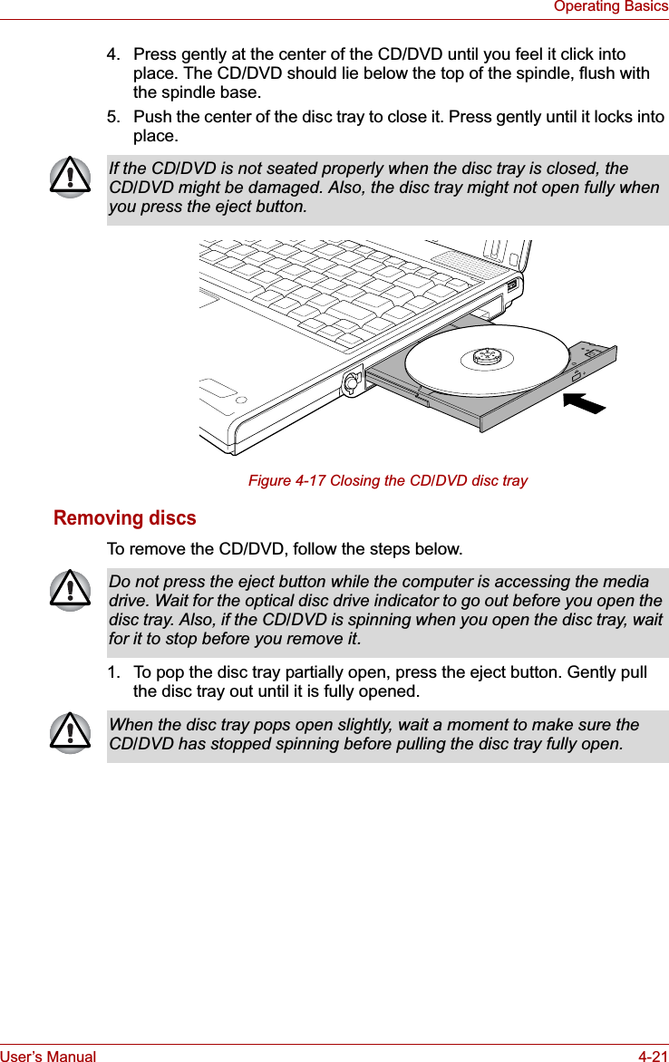
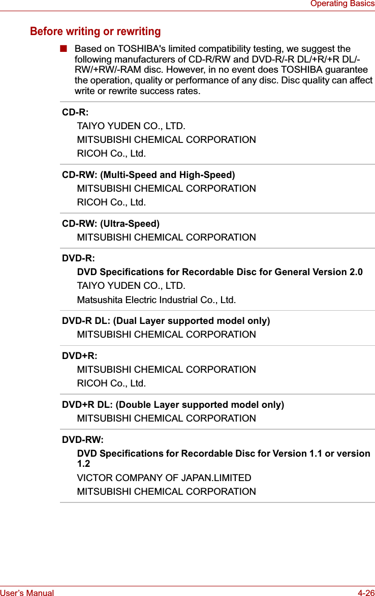
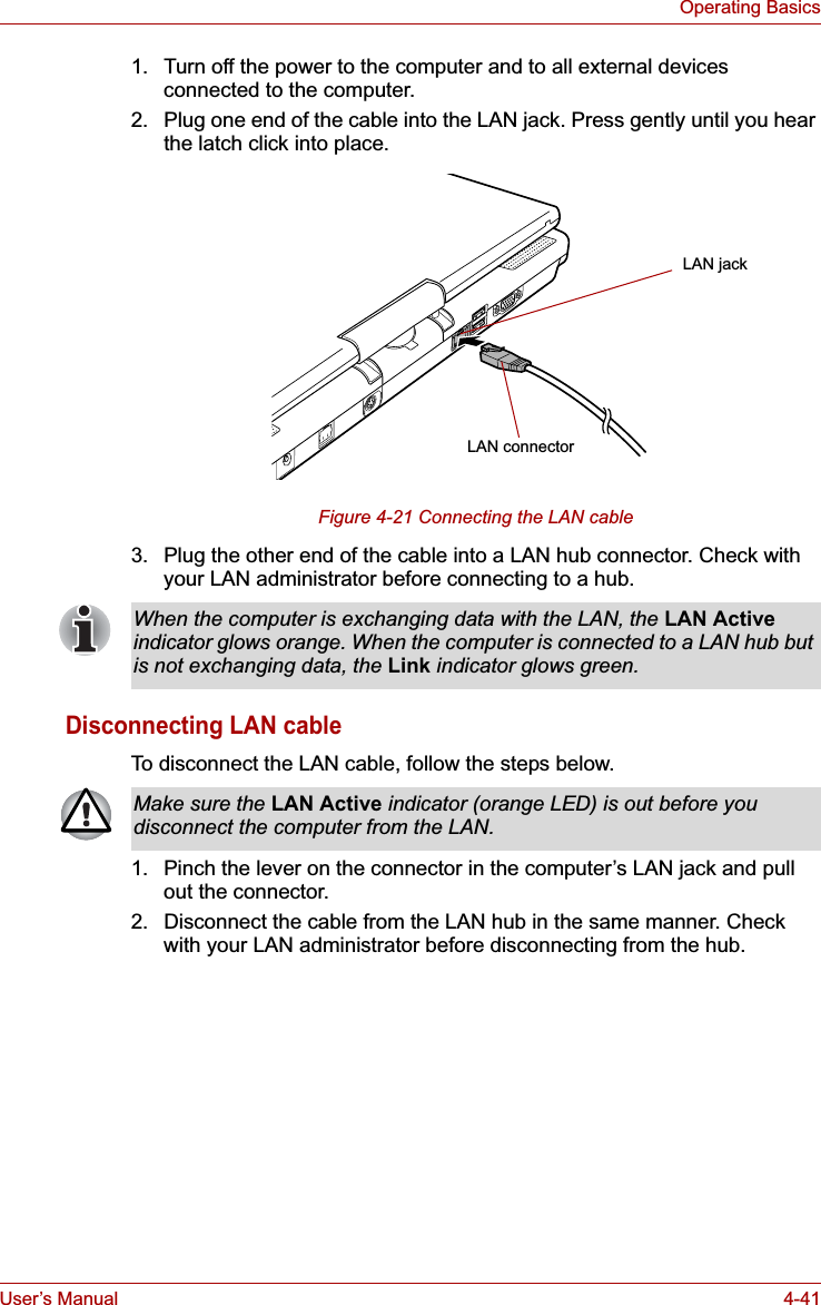
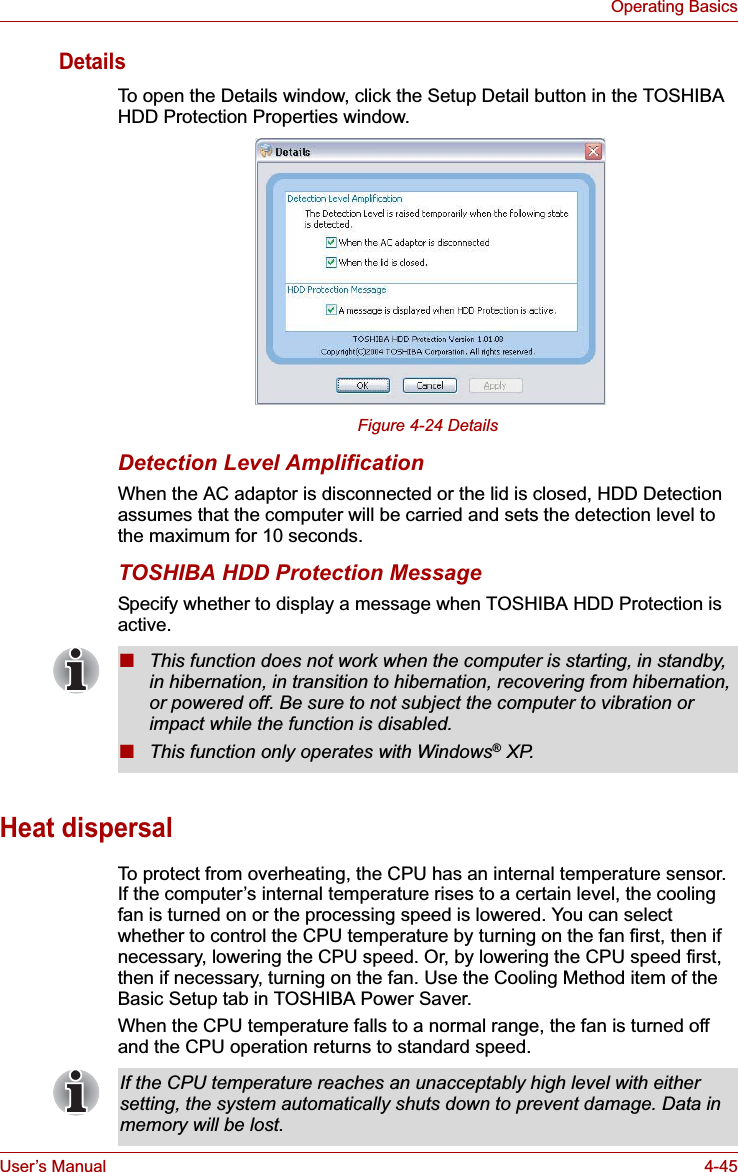
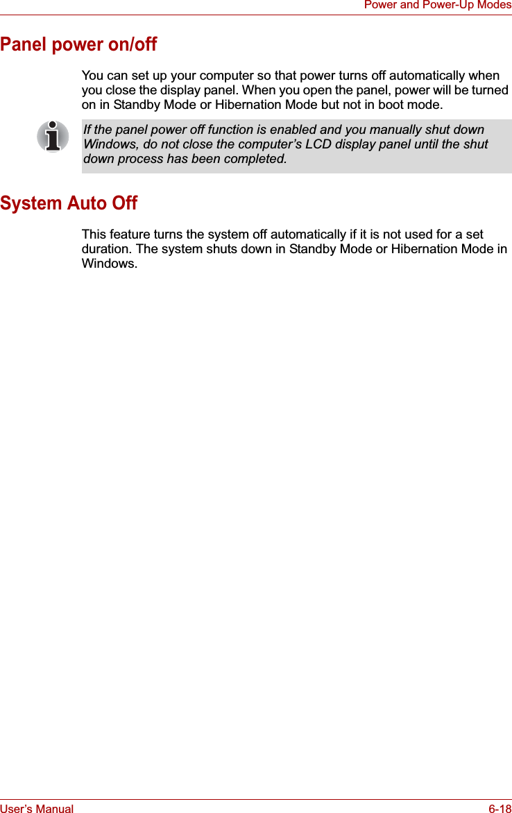
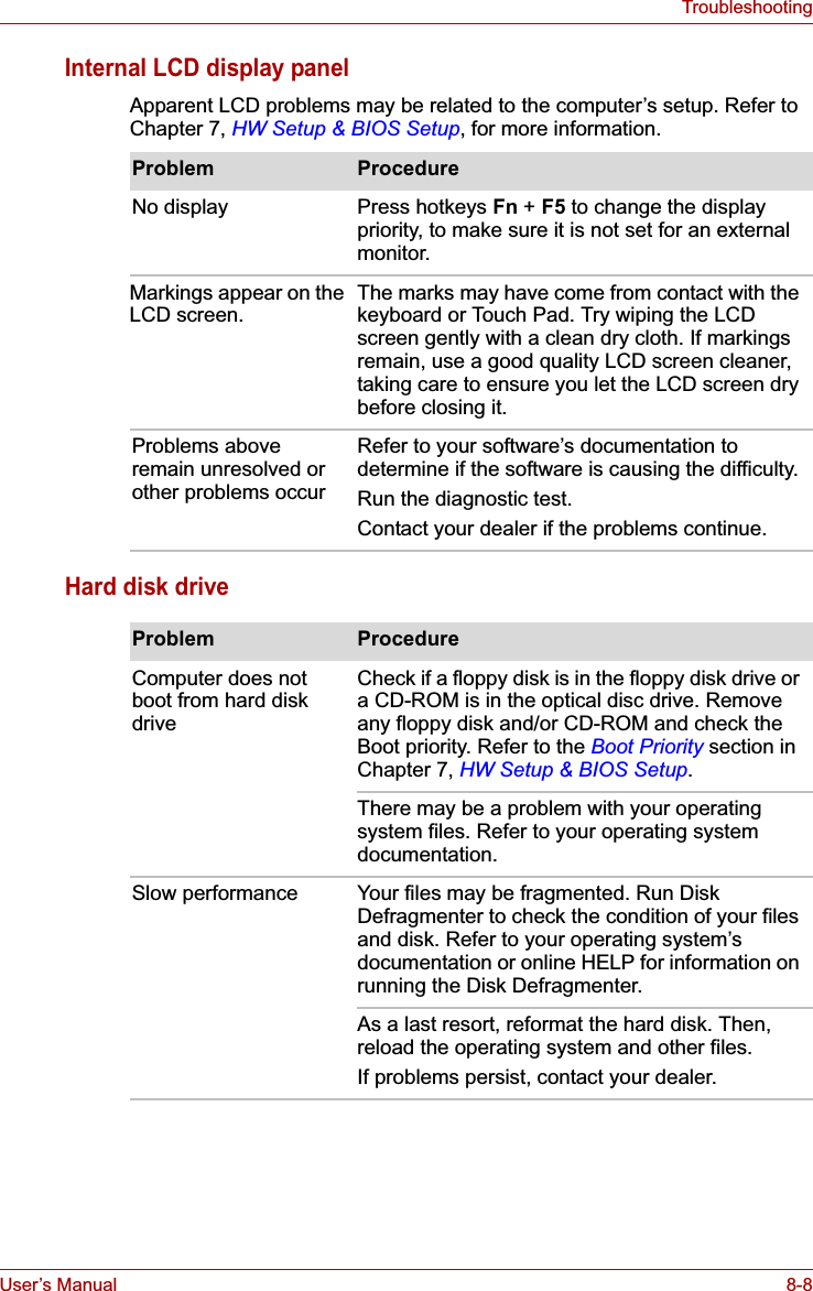
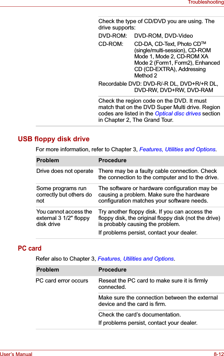
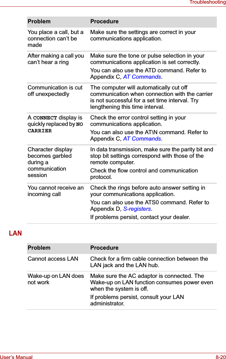
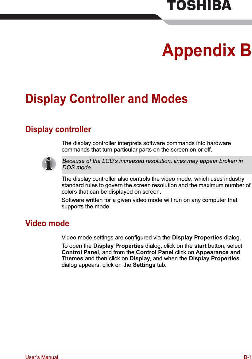
![User’s Manual 4-11Operating BasicsMethod 3: Changing the screen orientation using Task Bar1. Right click "Change tablet and pen settings" icon in the Task Bar. Click "Change screen orientation" from the menu.The screen orientation is set to change in the following order when purchased.You can change the above sequence through the following procedure:1. Double click Change tablet and pen settings icon in the Task Bar.2. Click Change button in Display tab.3. Select "changing the screen" from the Screen Orientation pull down menu and change the screen.Using Accelerometer UtilitiesYou can set the orientation of the desktop screen just after rotating the display from [Start]-[All Programs]-[TOSHIBA]-[Tablet PC]-[TOSHIBA Rotation Utility].When you shake the computer:■Do not shake the computer too strongly as this may cause the computer to be dropped or hit those people or items around you.■Avoid using the computer in crowded places (e.g. in commuter trains or in busy streets).■This may cause injury to children or adults, or damage to the computer.When the TOSHIBA HDD protection function is turned on and the Tilt function (function to start applications, etc. by waving the computer vertically or horizontally) is used, the TOSHIBA HDD protection message may be displayed on the screen. Turn off the TOSHIBA HDD protection function in order to stop such messages from displaying.](https://usermanual.wiki/Dynabook/UPA3503WL.TECRA-M7-User-Manual/User-Guide-693494-Page-106.png)
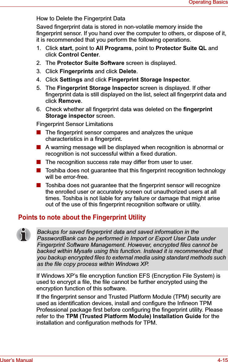
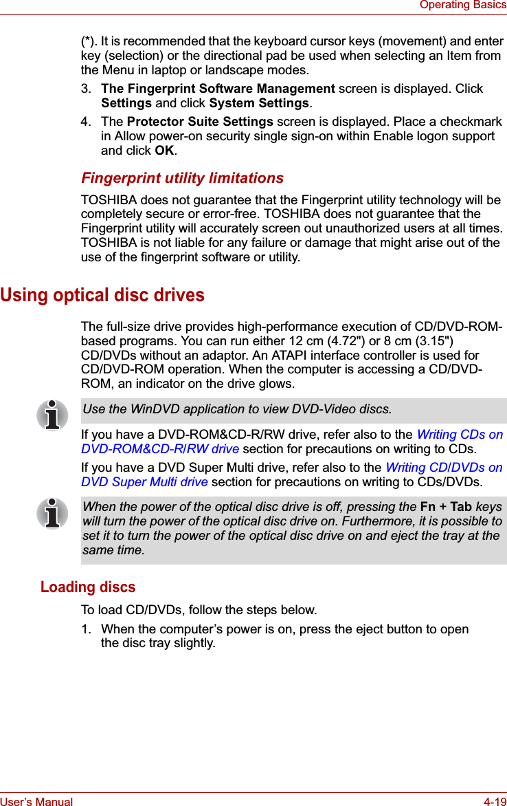
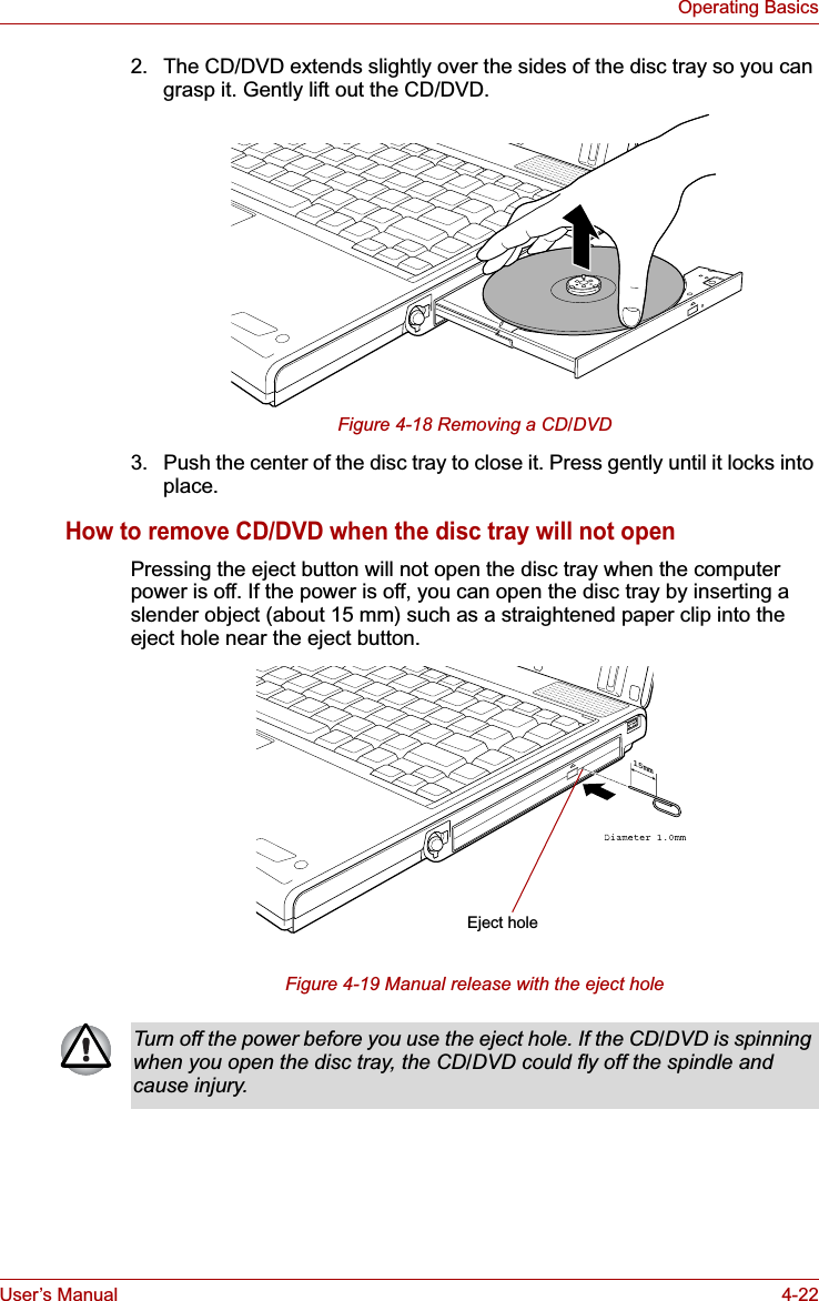
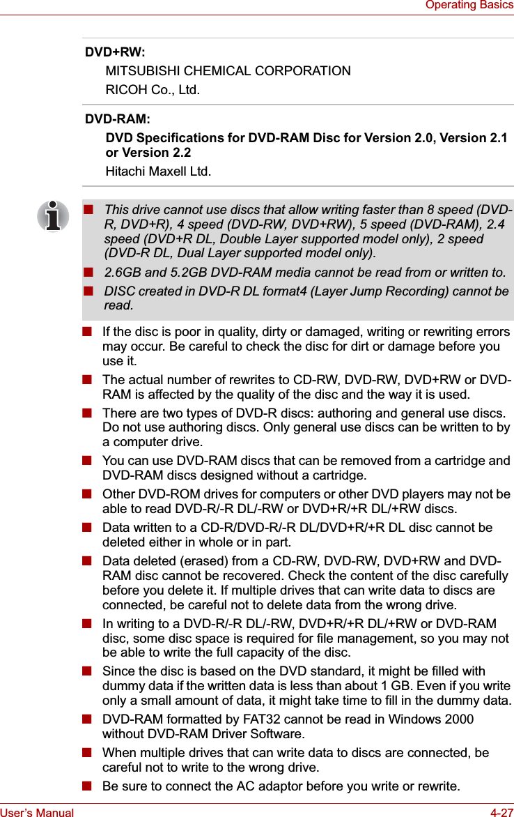
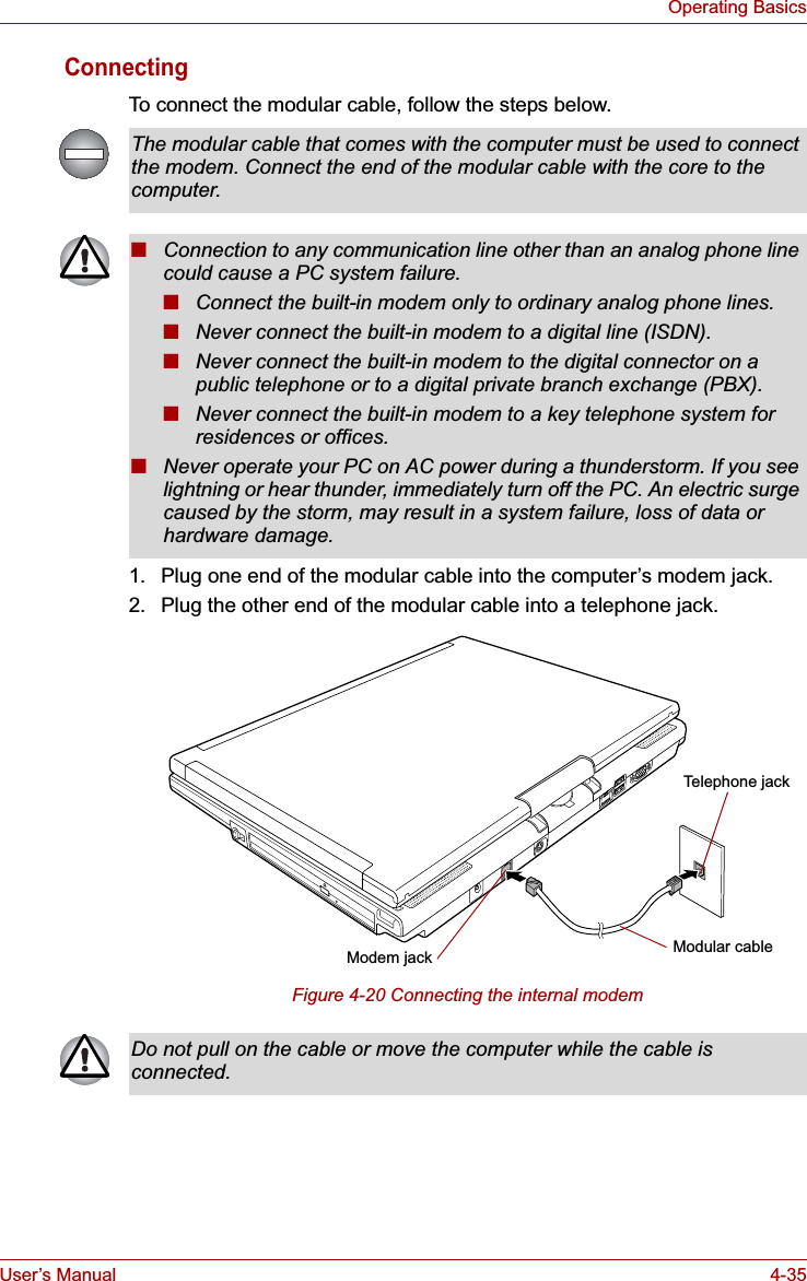
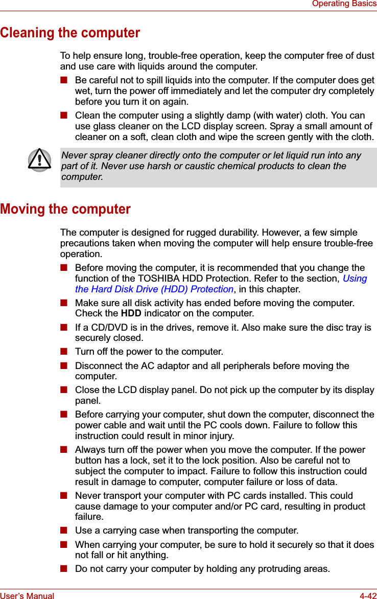
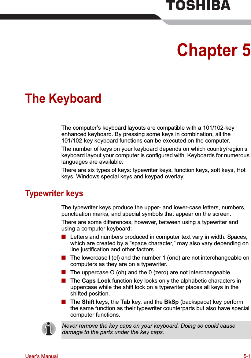
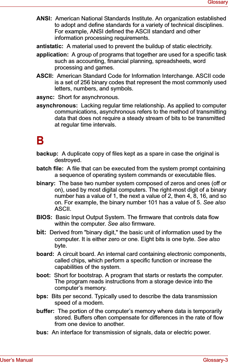
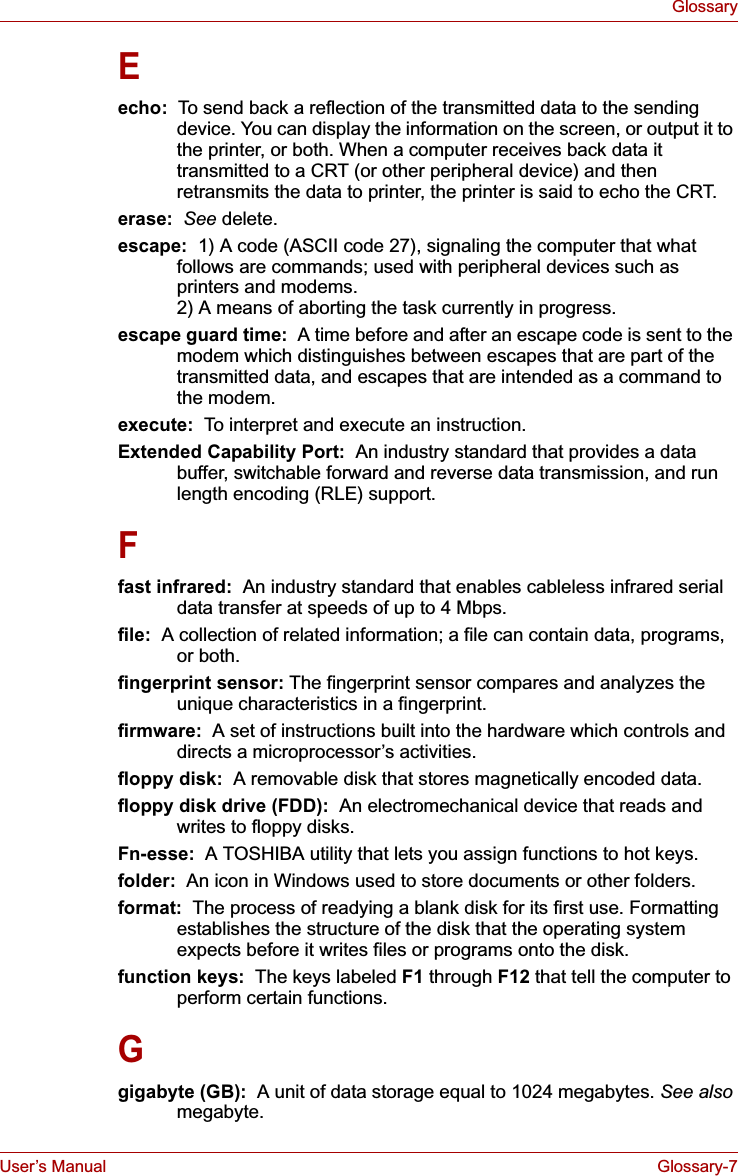
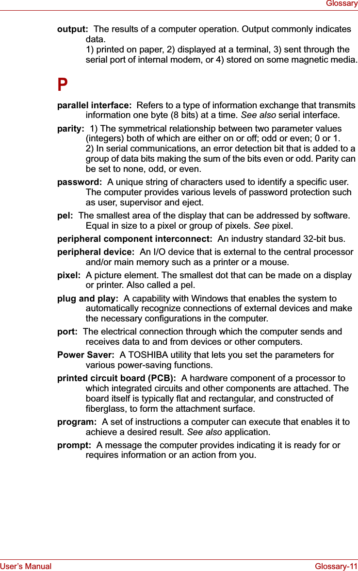
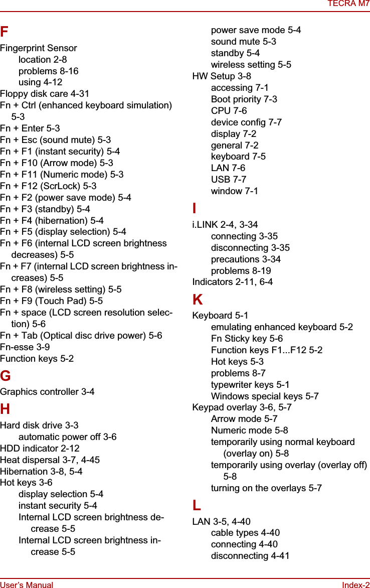
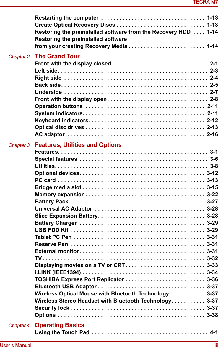
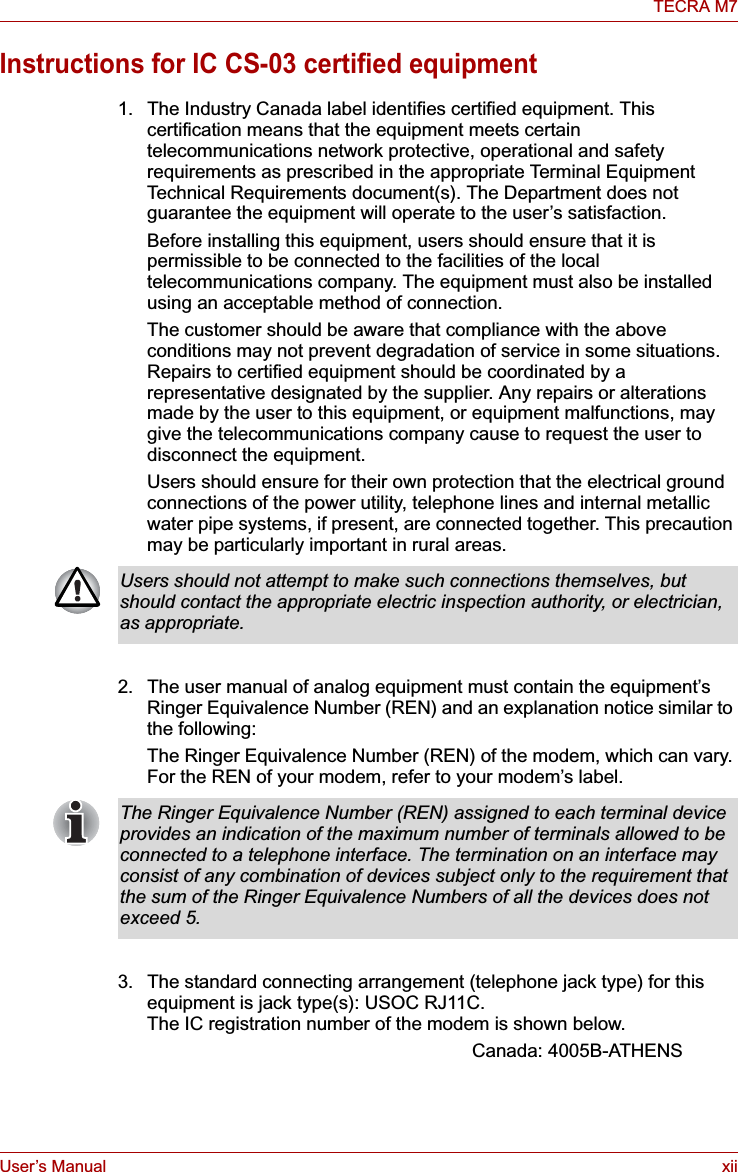
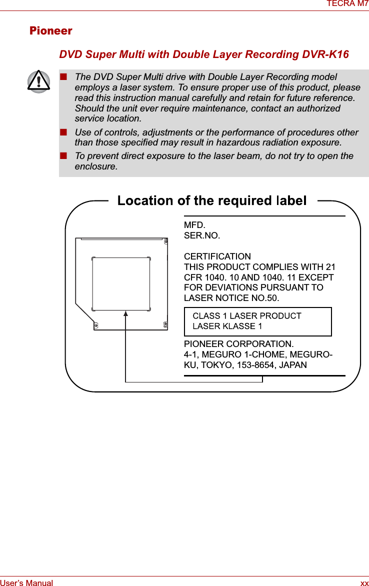
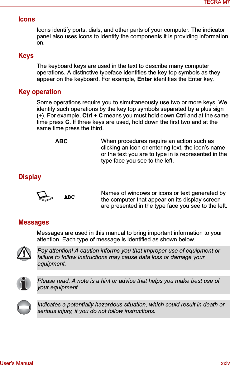
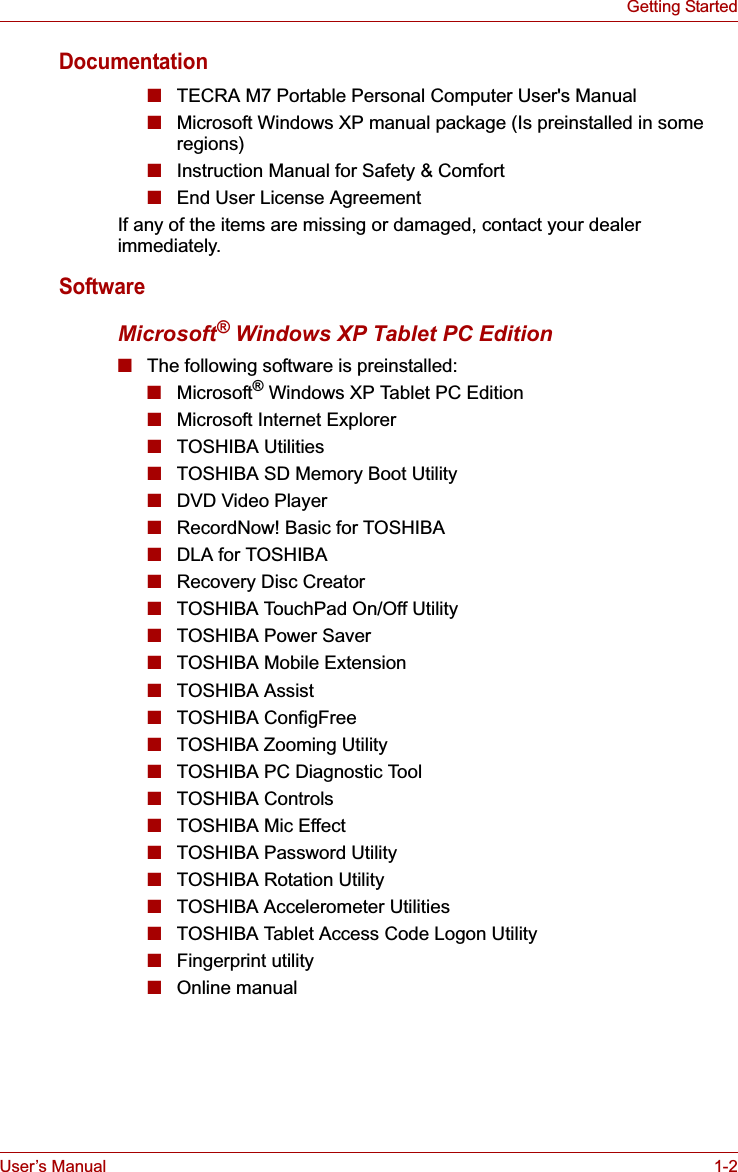
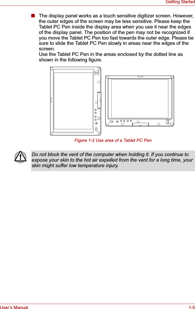
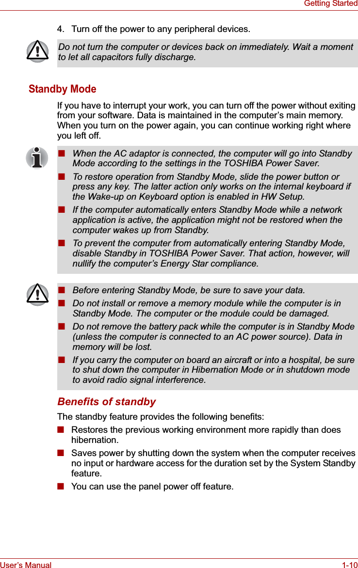
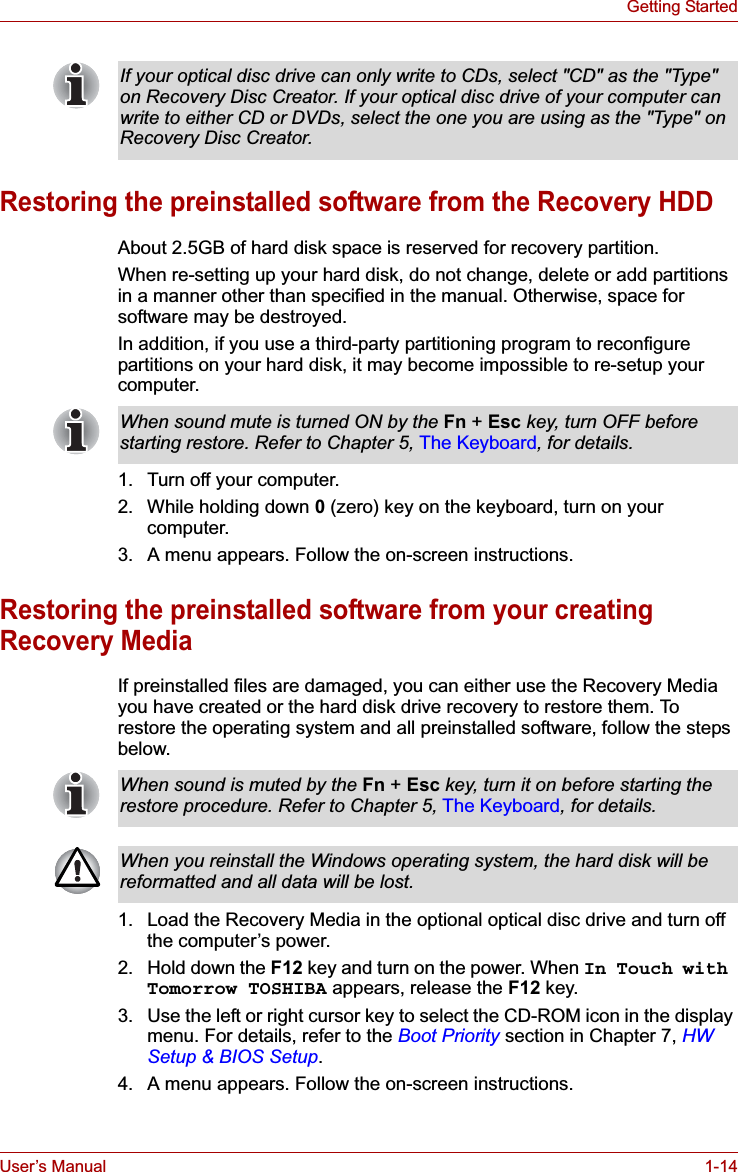
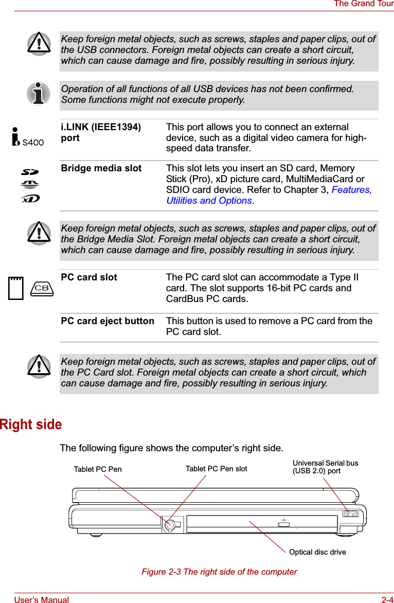
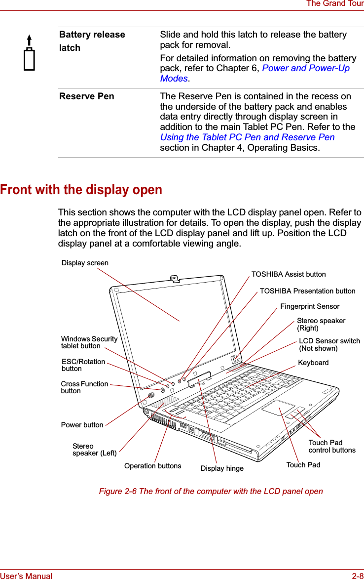
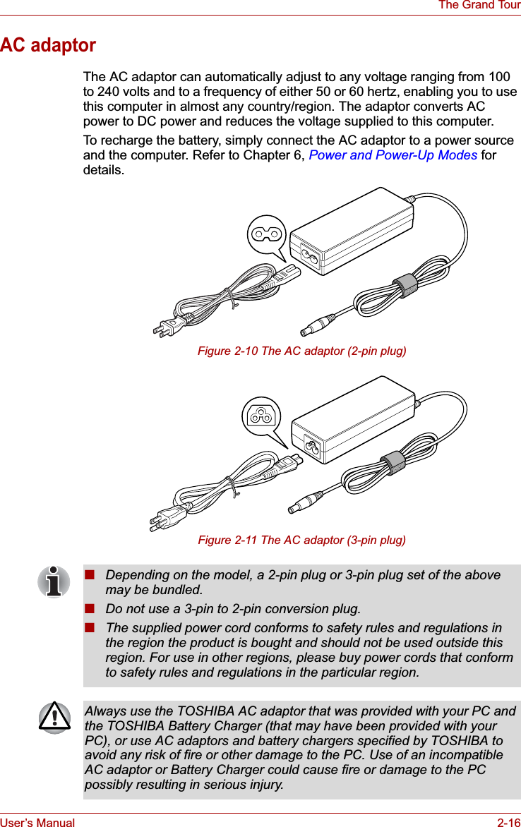
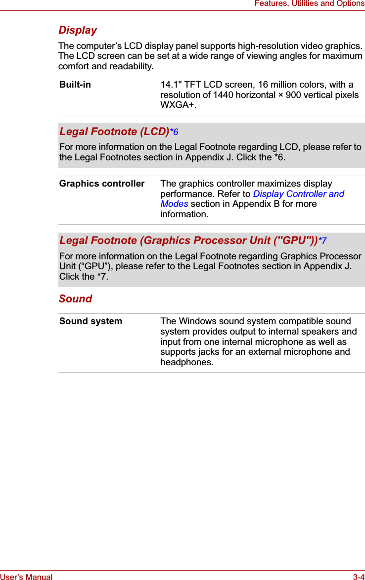
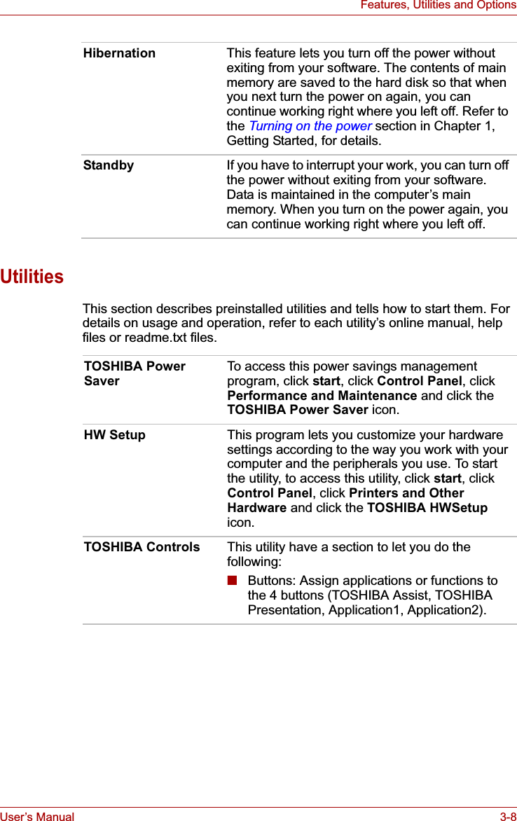
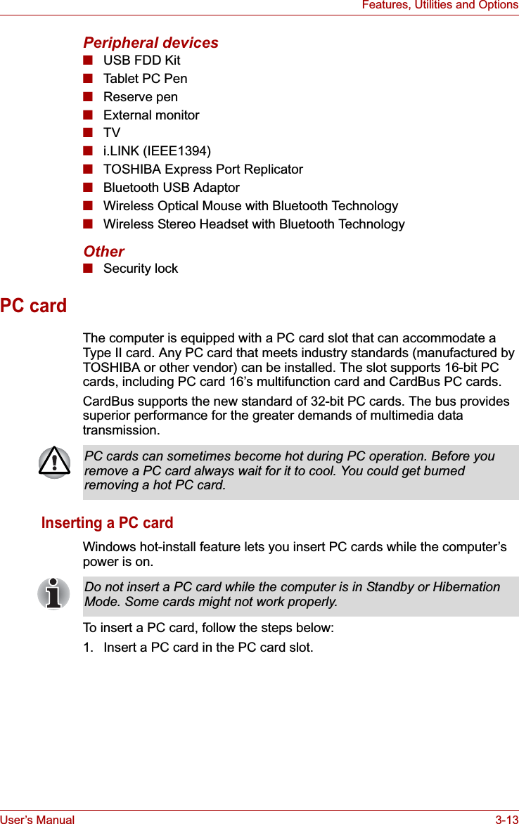
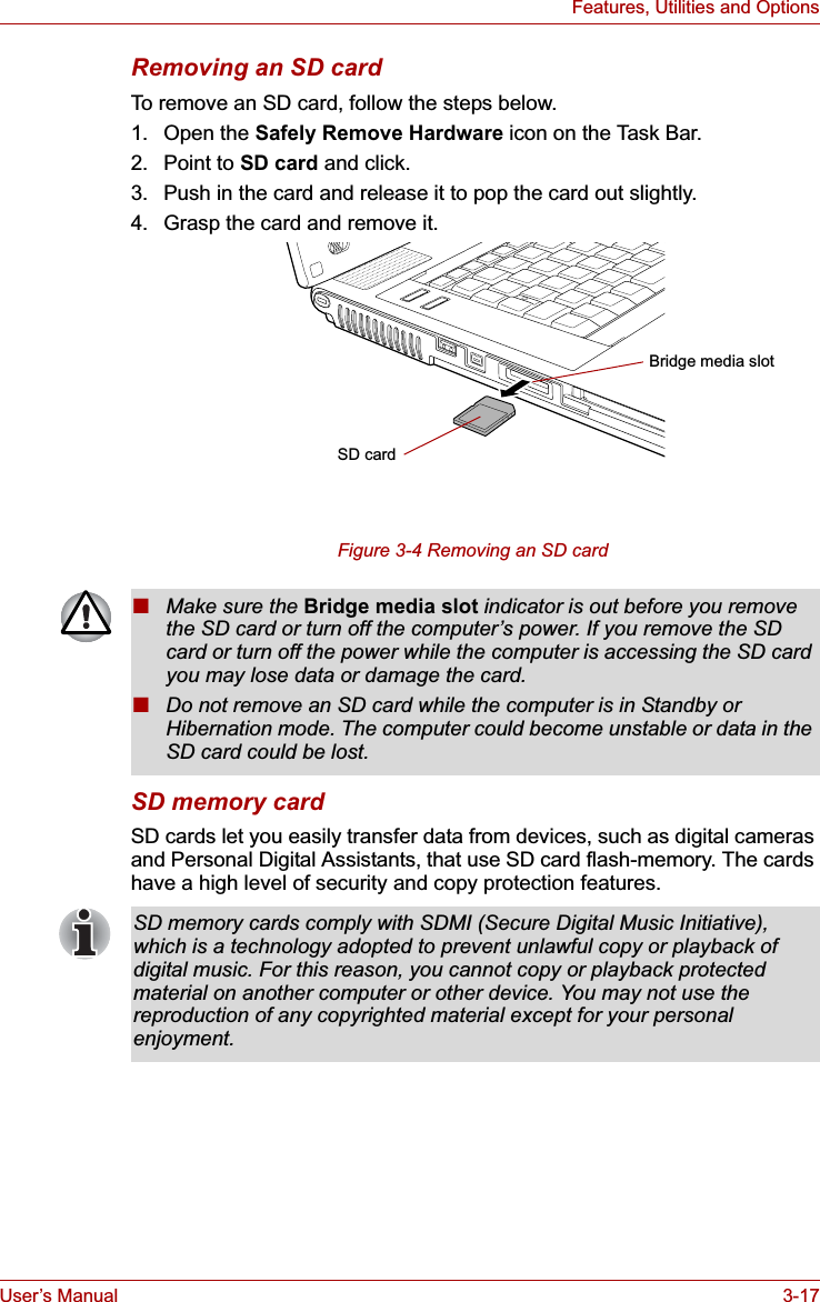
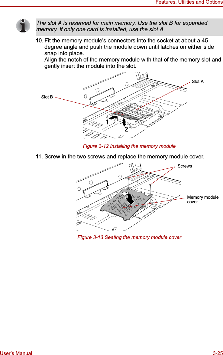
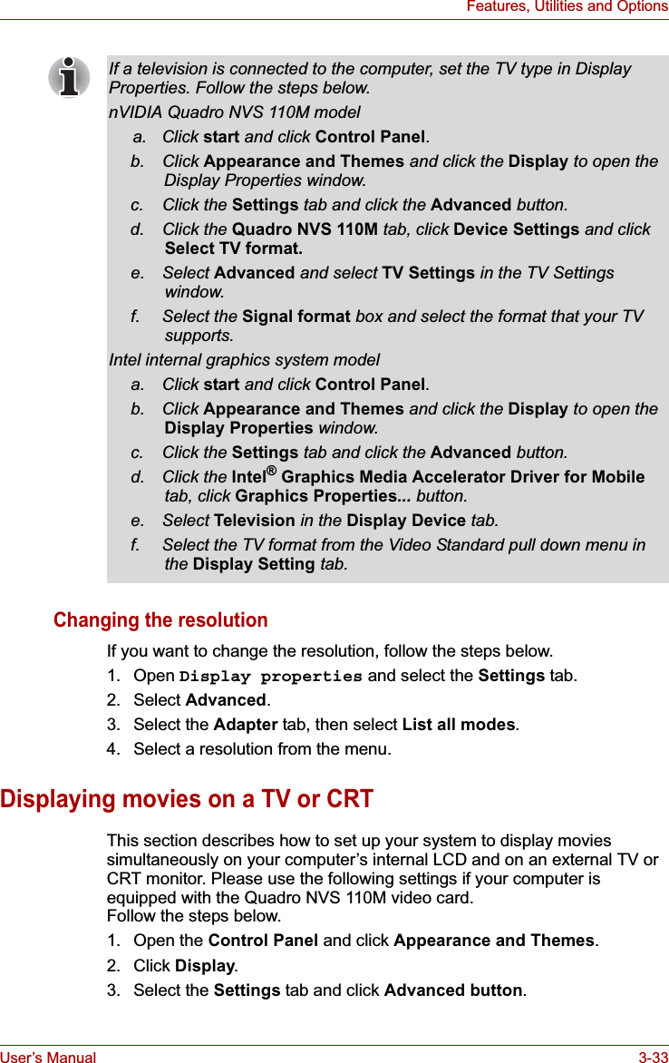
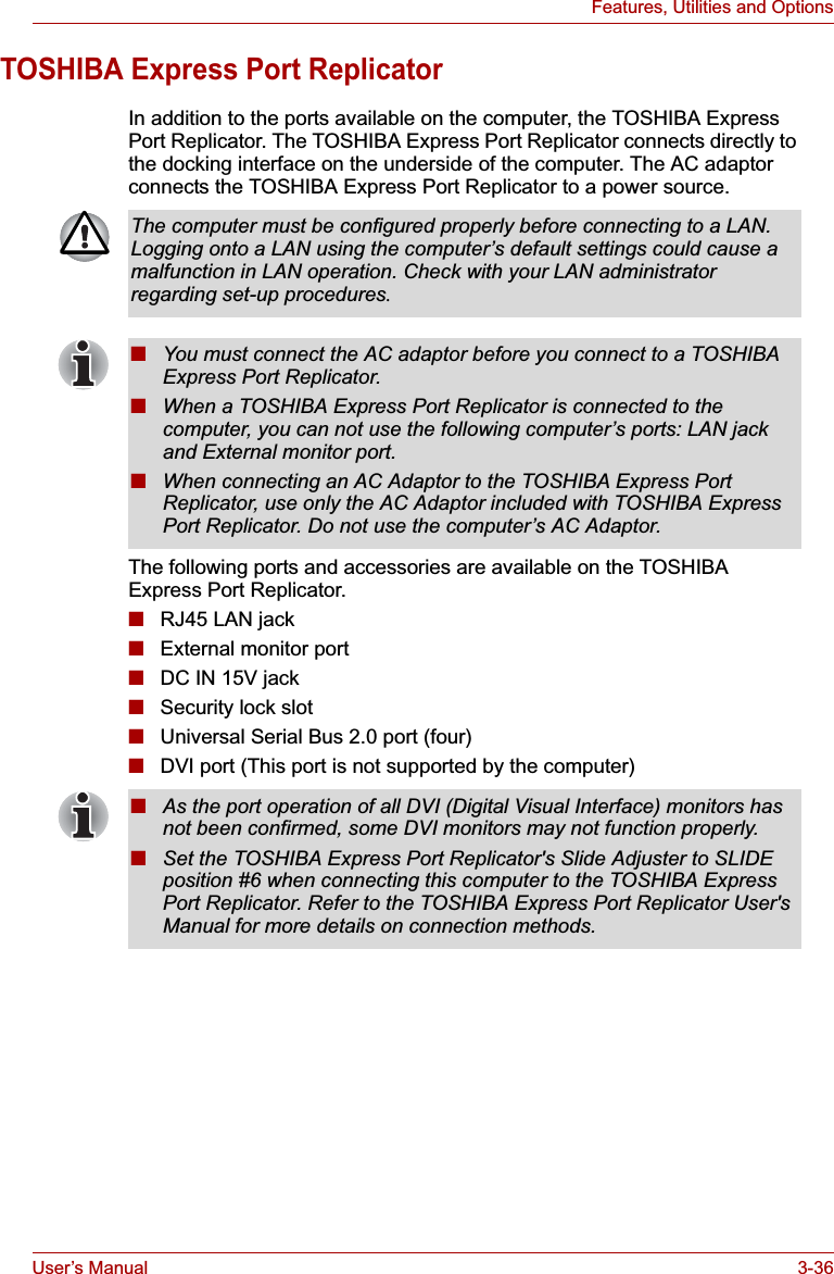
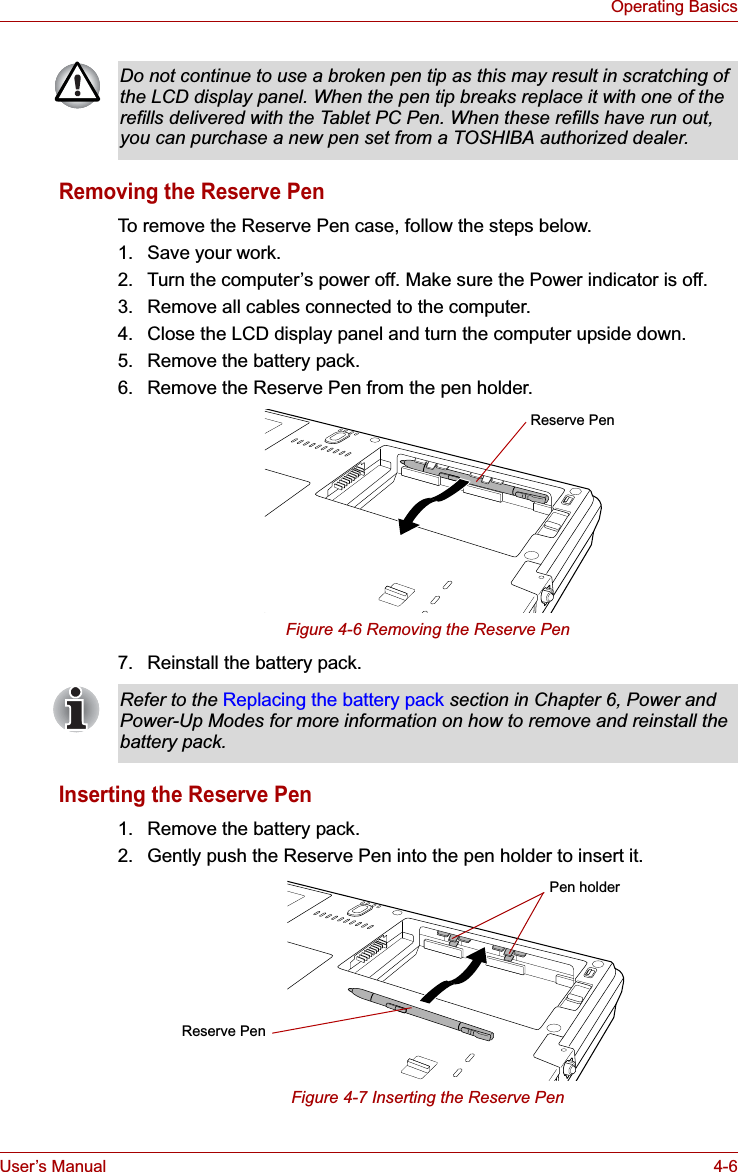
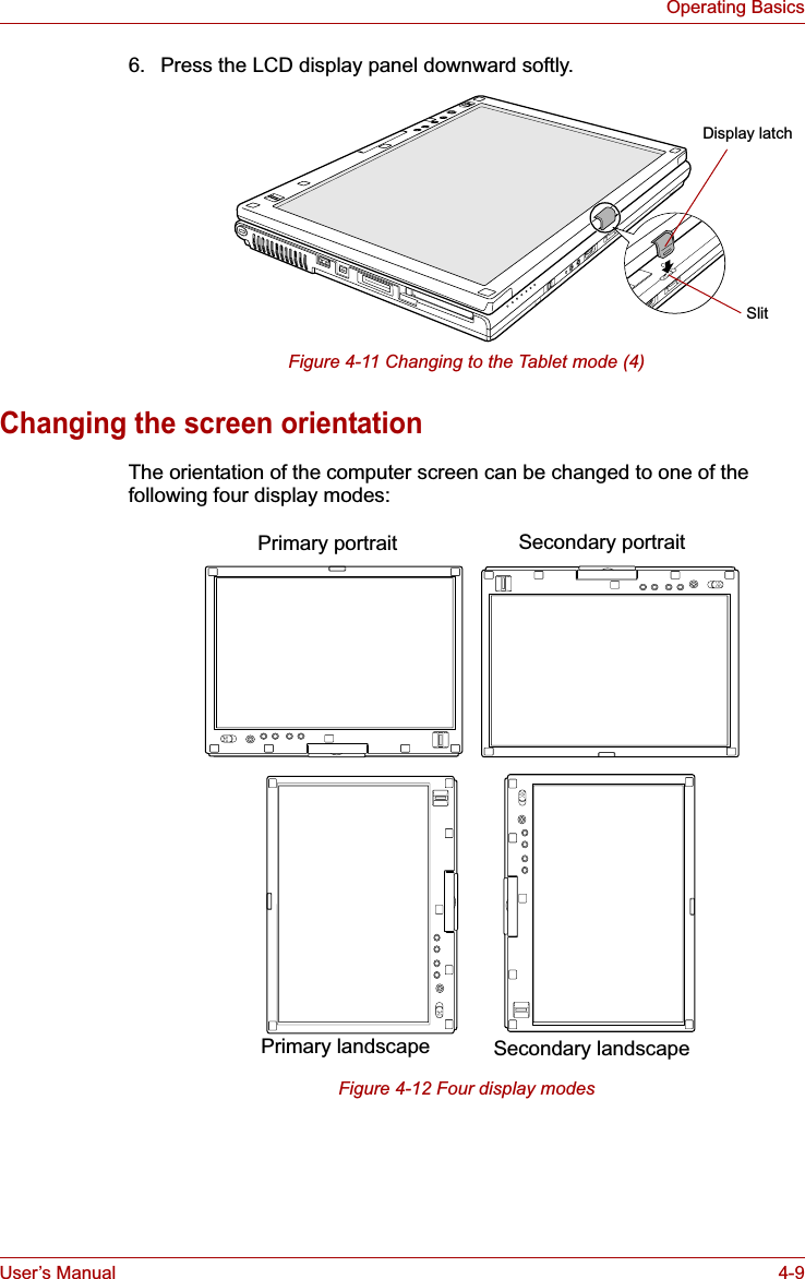
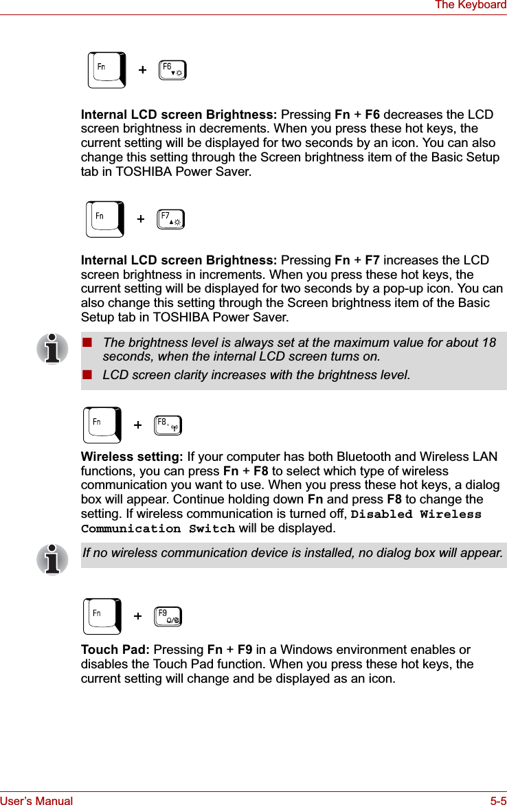
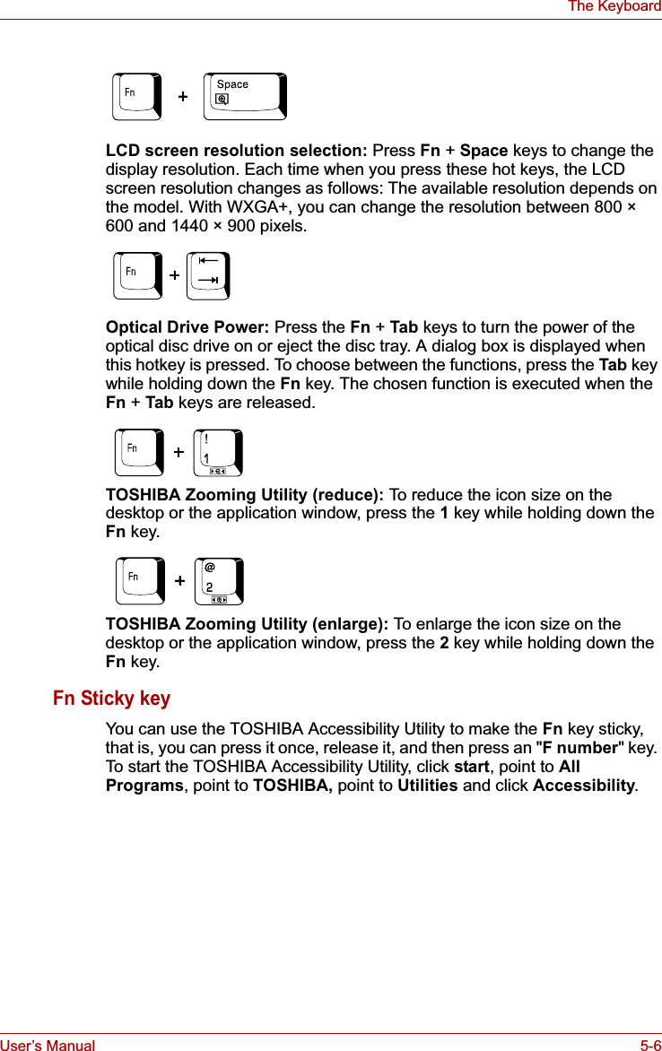
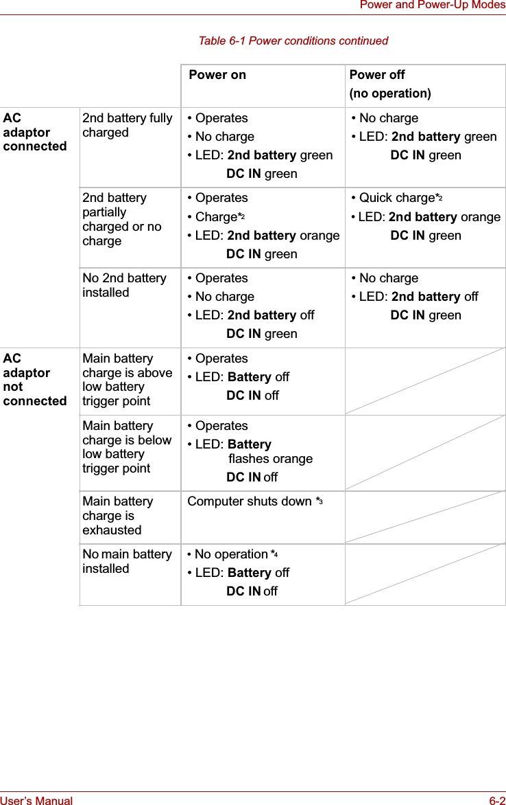
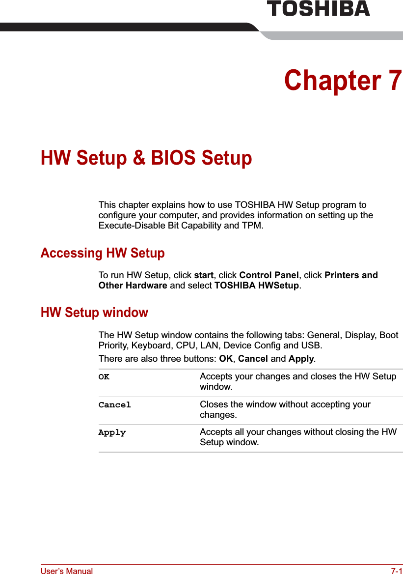
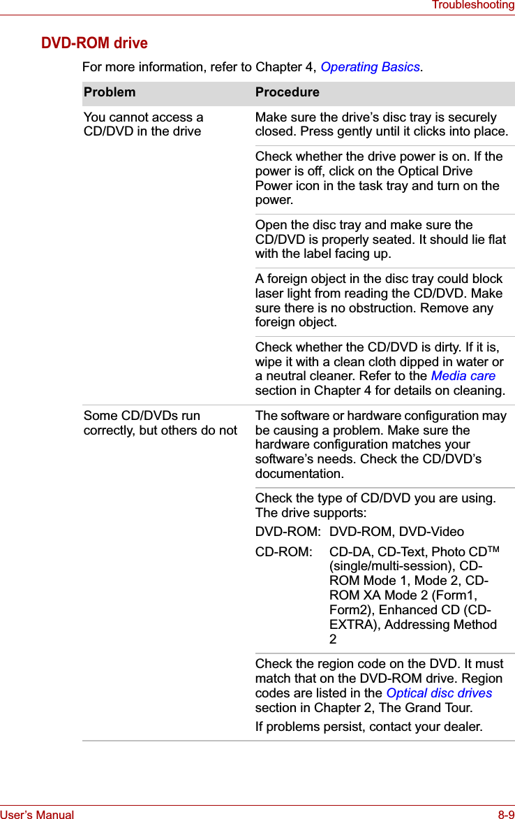
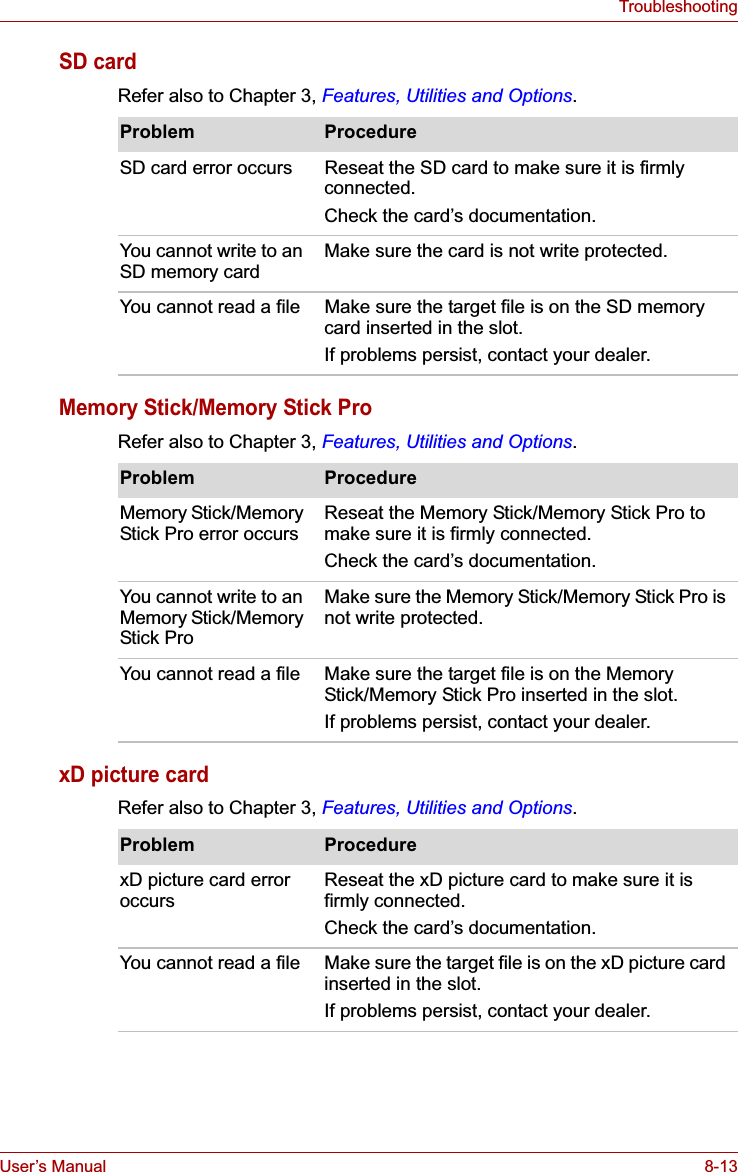
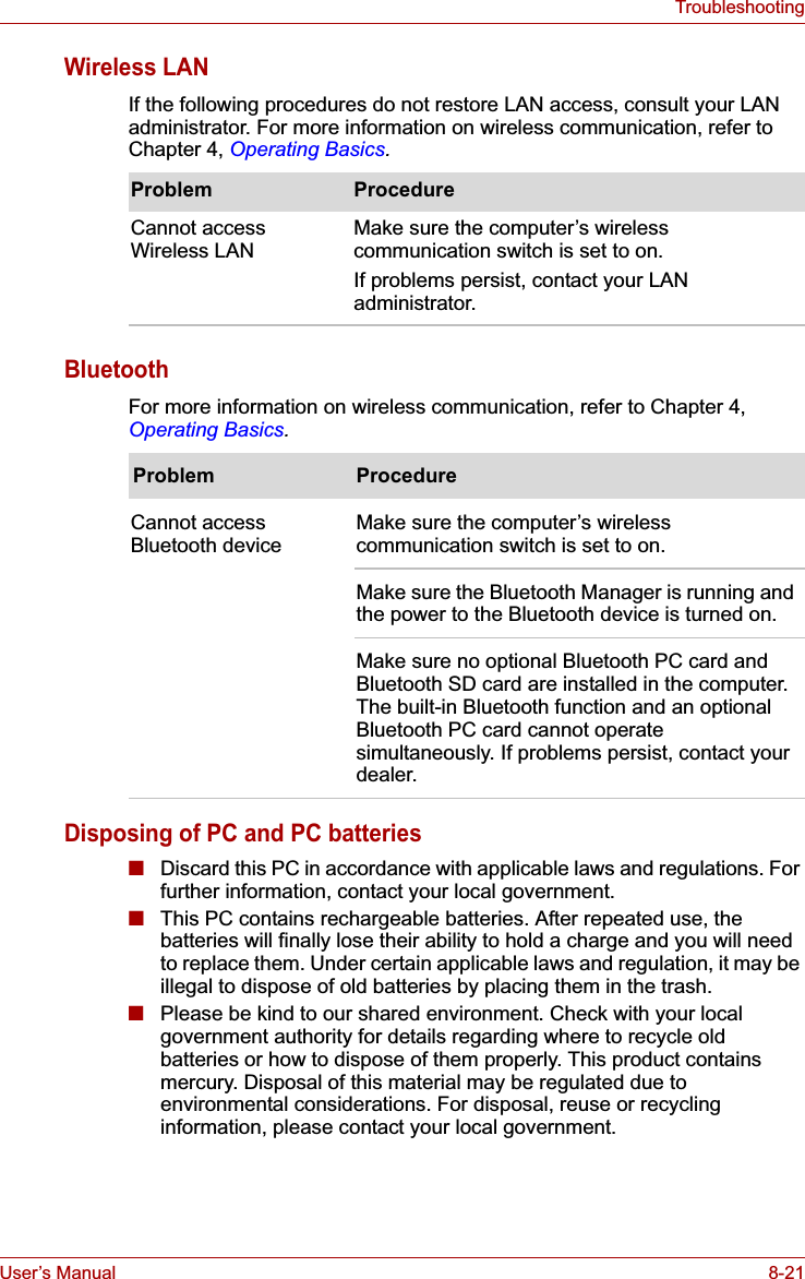
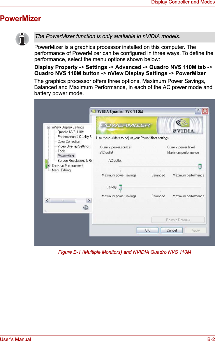
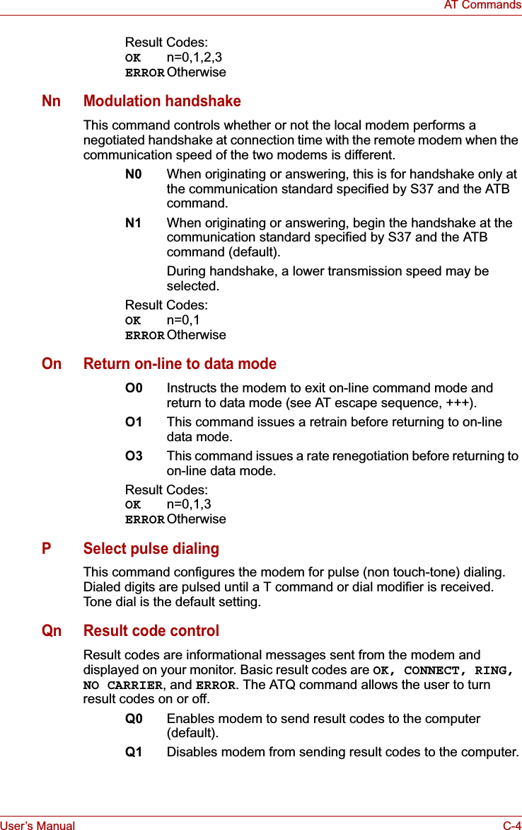
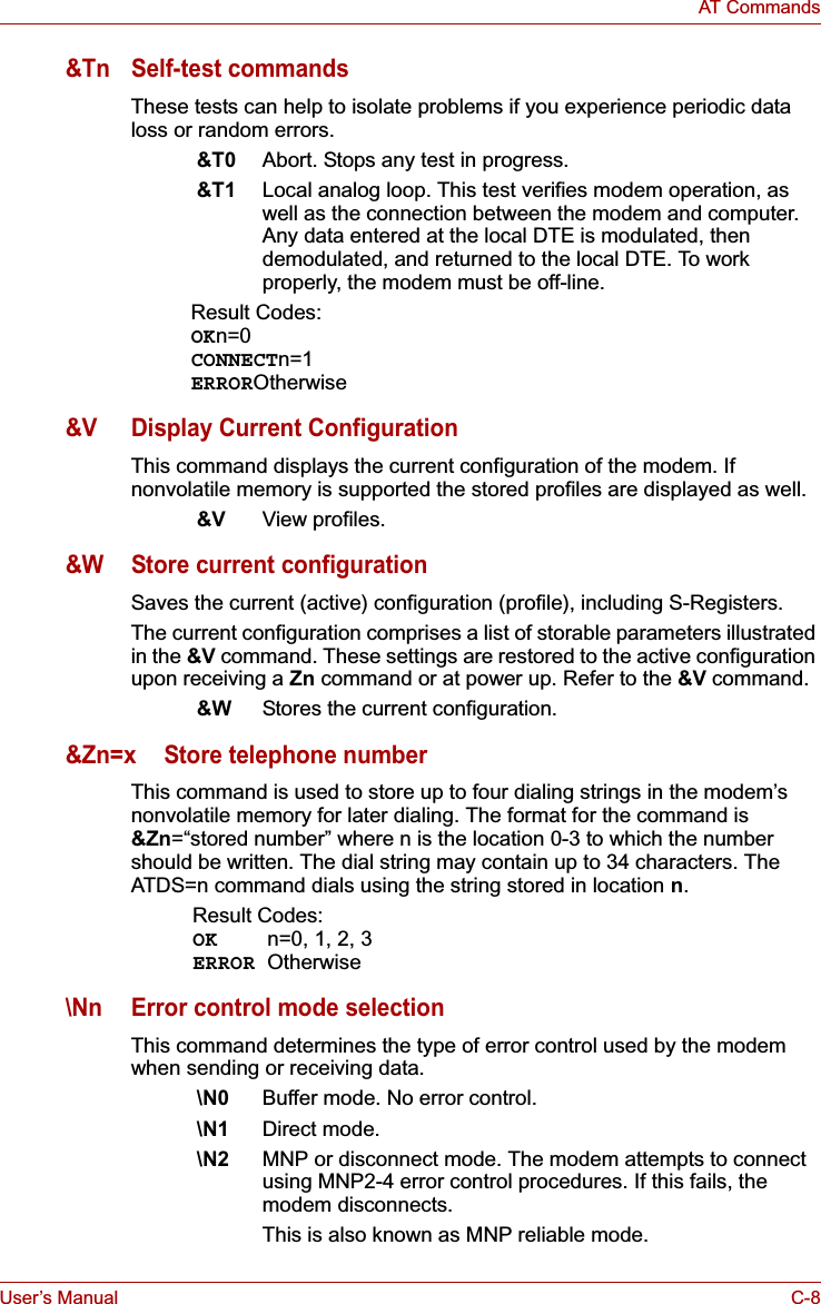
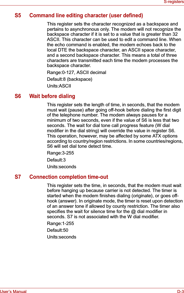
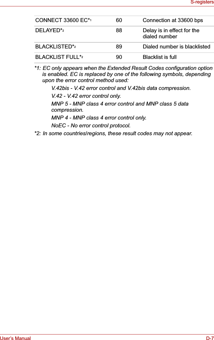
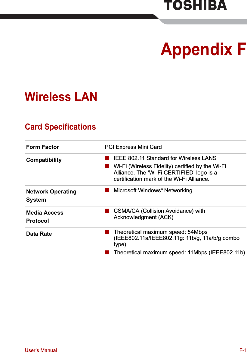
![User’s Manual 5-2The KeyboardFunction keys: F1 … F12The function keys (not to be confused with Fn) are the 12 keys at the top of your keyboard. These keys function differently from other keys.F1 through F12 are called function keys because they execute programmed functions when pressed. Used in combination with the Fnkey, keys marked with icons execute specific functions on the computer. Refer to the section, Soft keys: Fn key combinations, in this chapter. The function executed by individual keys depends on the software you are using. Soft keys: Fn key combinationsThe Fn (function) is unique to TOSHIBA computers and is used in combination with other keys to form soft keys. Soft keys are key combinations that enable, disable or configure specific features.Emulating keys on enhanced keyboardFigure 5-1 A 101-key enhanced keyboard layoutThe keyboard is designed to provide all the features of the 101-key enhanced keyboard. The 101/102-key enhanced keyboard has a numeric keypad and scroll lock key. It also has additional Enter and Ctrl keys to the right of the main keyboard. Since the keyboard is smaller and has fewer keys, some of the enhanced keyboard functions must be simulated using two keys instead of one on the larger keyboard.Your software may require you to use keys that the keyboard does not have. Pressing the Fn key and one of the following keys simulates the enhanced keyboard’s functions.Some software may disable or interfere with soft-key operations. Soft-key settings are not restored by the Standby feature.Esc#3Home PgUpBk SpF1 F2 F3 F4 F5 F6 F7 F8 F9 F10 F11 F12 ! 12$4%568 (9 )0&7_+=PgDnEndShiftDelInsCapsLockShiftEnterQW RTYU I O P {[}]E~`ASDFGHJ KL:;@?/> .< ,MNVCXZB\^*+-TabAltAltEnter 7Home8 9PgUp654 1End2 3PgDn 0InsNumLock .Del PrtSc Scroll lockPauseBreakCtrlCtrlSysReq/*.,,,](https://usermanual.wiki/Dynabook/UPA3503WL.TECRA-M7-User-Manual/User-Guide-693494-Page-142.png)
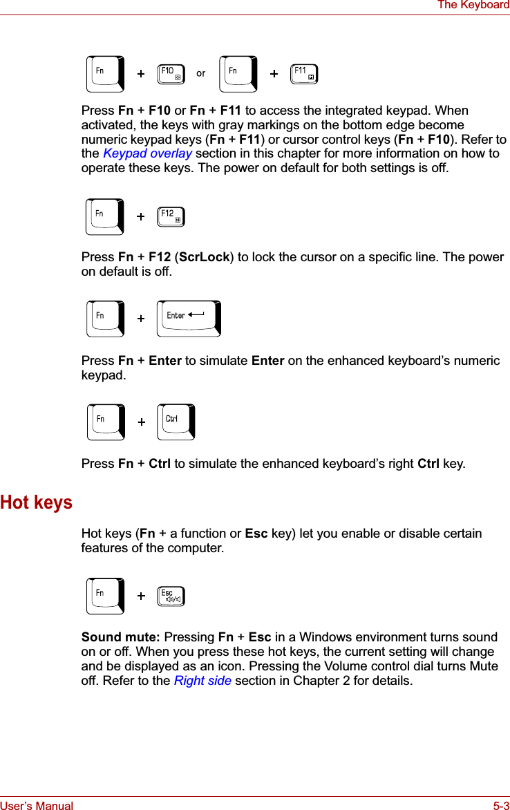
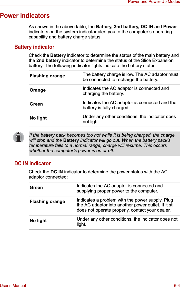
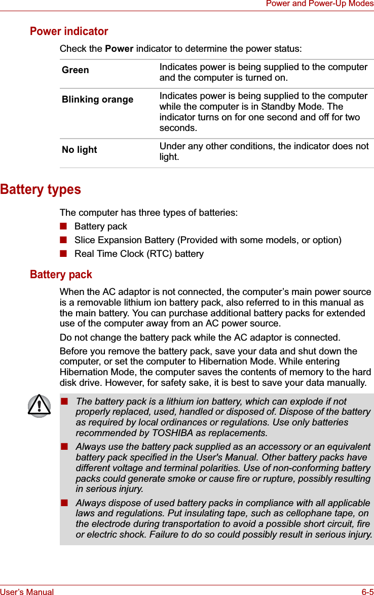
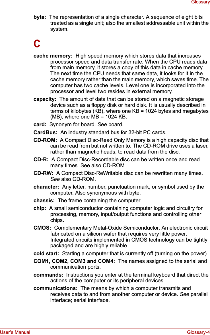
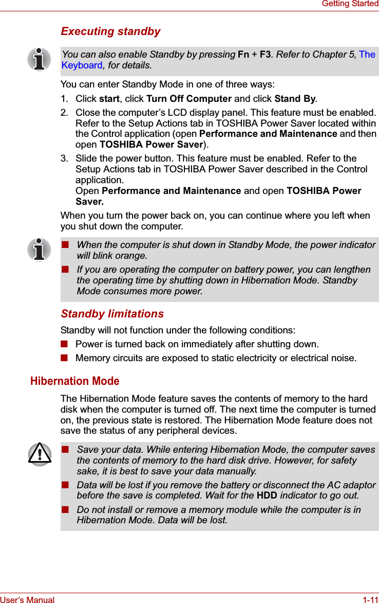
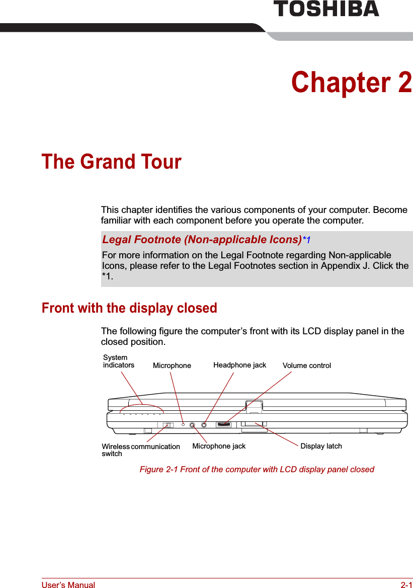
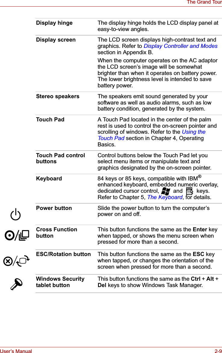
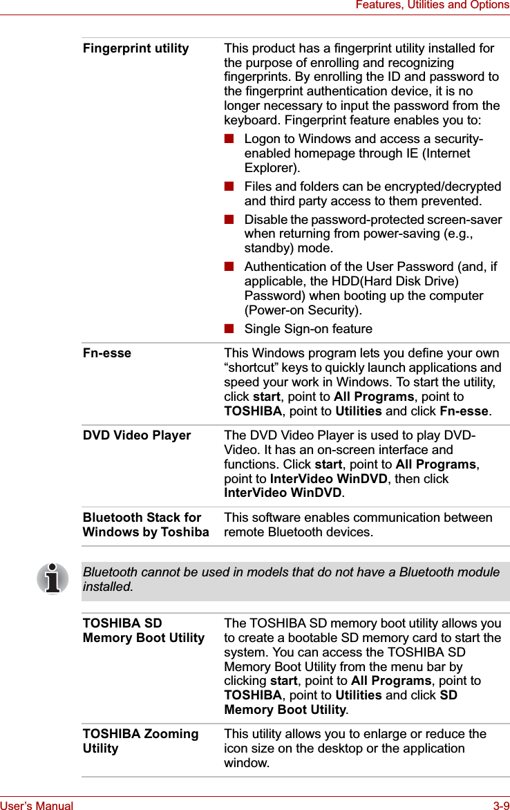
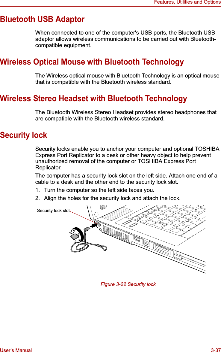
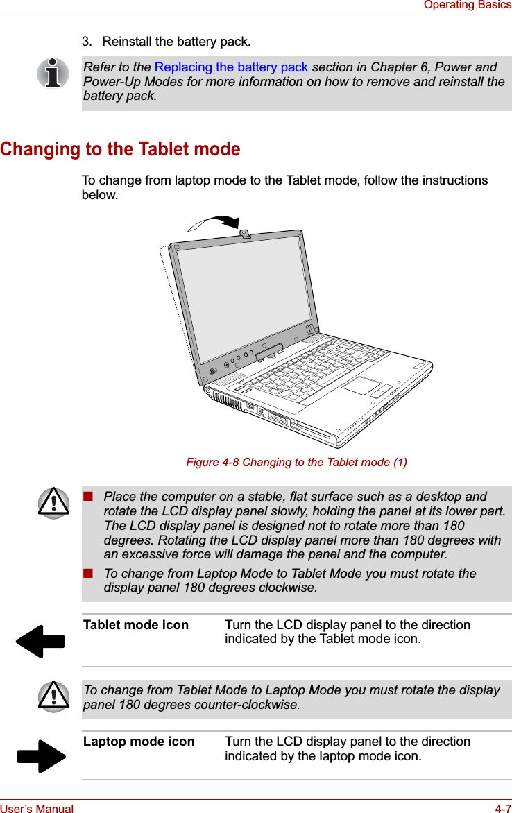
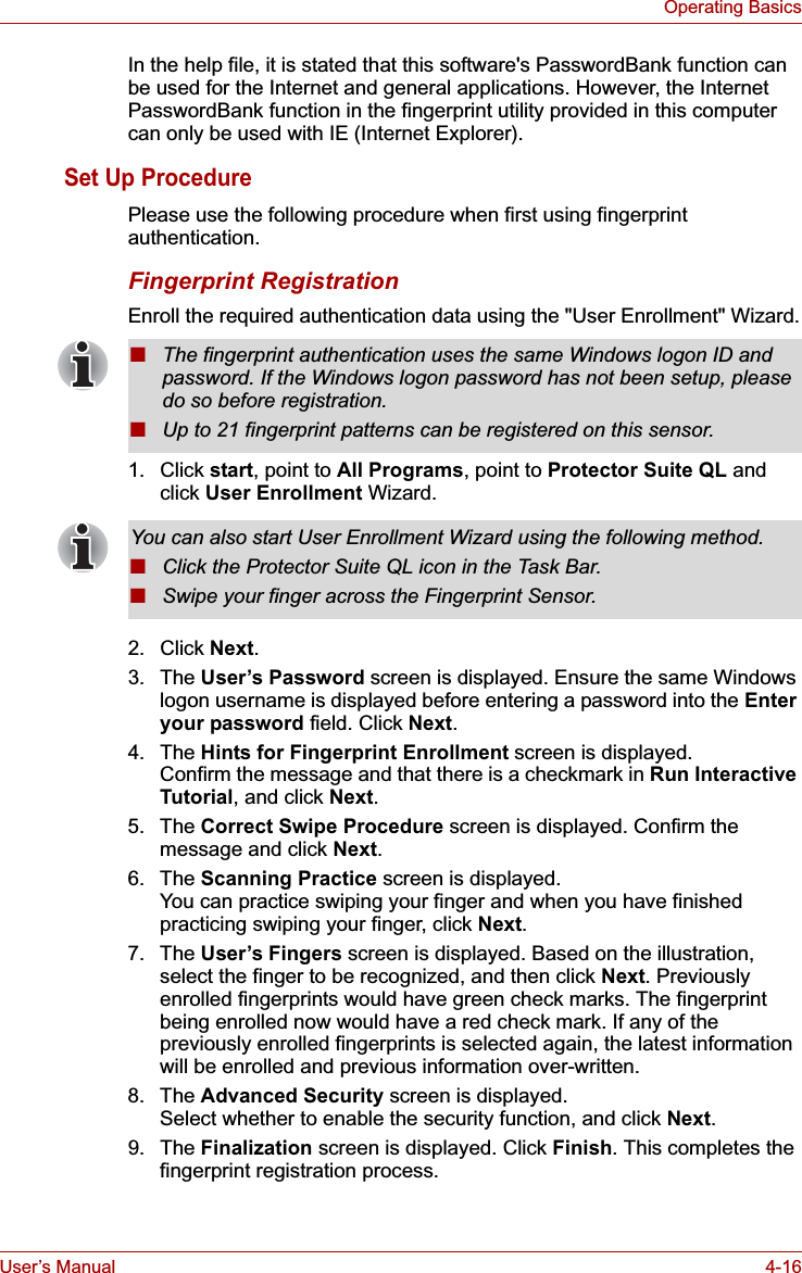
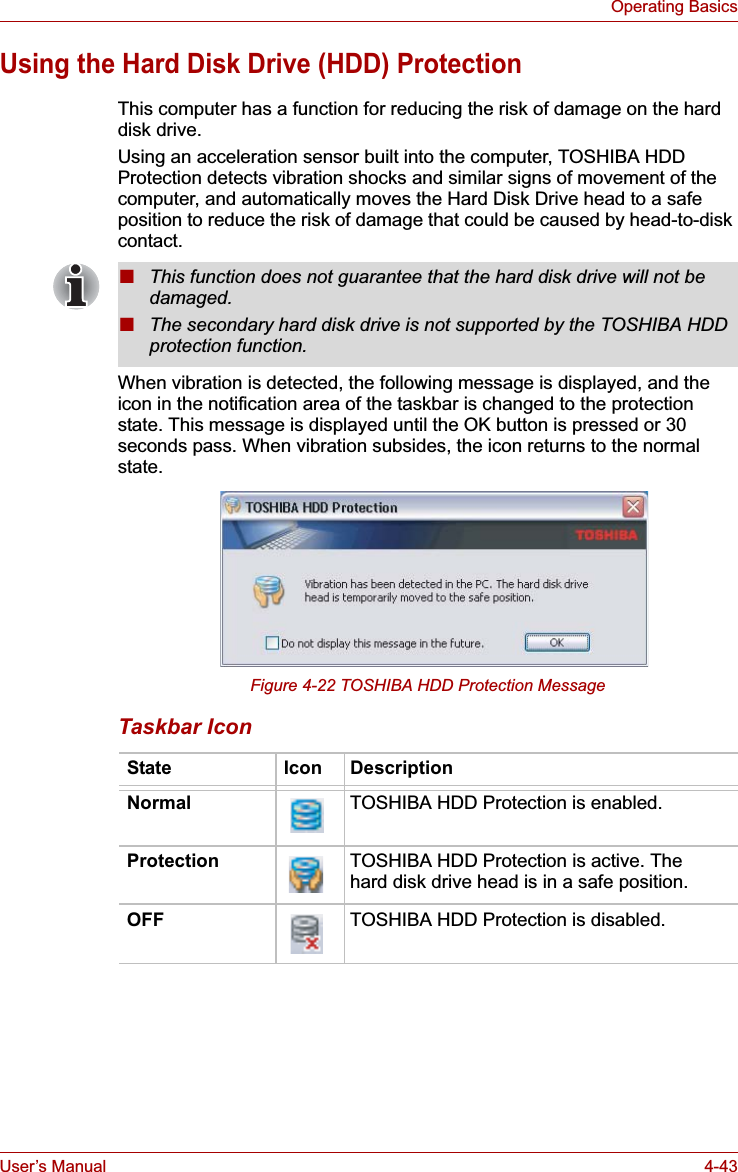
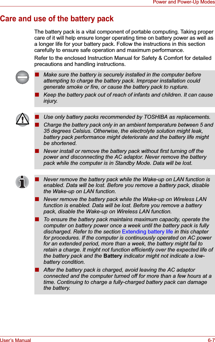
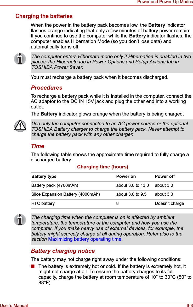
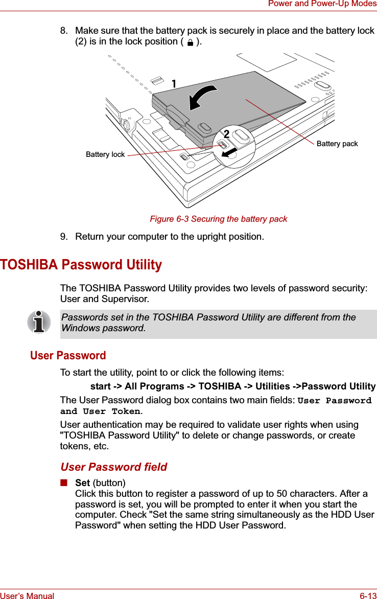
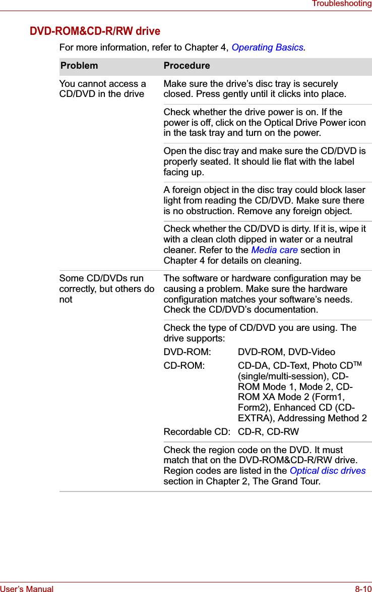
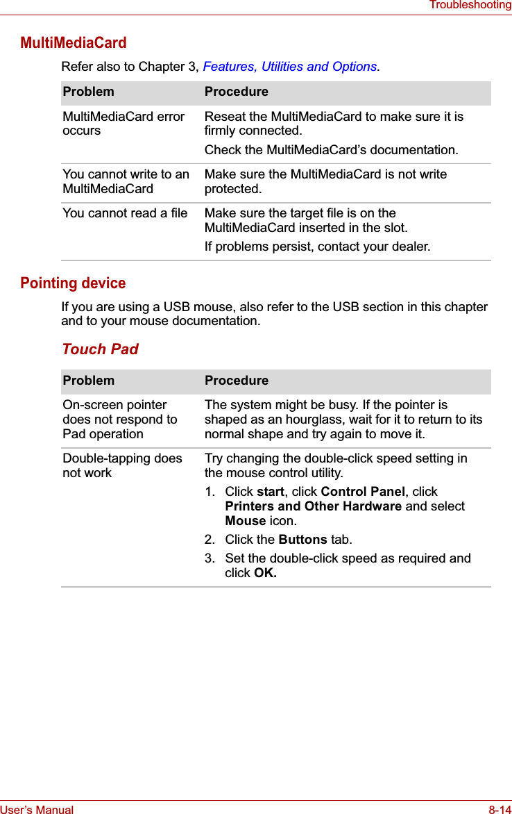
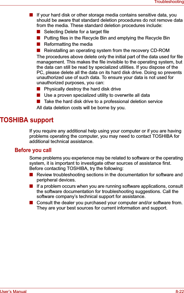
![User’s Manual 6-6Power and Power-Up ModesTo ensure that the battery pack maintains its maximum capacity, operate the computer on battery power at least once a month until the battery pack is fully discharged. Refer to Extending battery life in this chapter for procedures. If the computer is continuously operated on AC power through an AC adaptor for an extended period, more than a month, the battery may fail to retain a charge. It may not function efficiently over the expected life of the battery and the Battery indicator may not indicate a low-battery condition.Slice Expansion Battery (Provided with some models, or option)The Slice Expansion Battery is included with some models, or can be purchased separately as an optional accessory.For detailed information on this battery, refer to Slice Expansion Batterysection in Chapter 3.Real Time Clock (RTC) batteryThe Real Time Clock (RTC) battery provides power for the internal real time clock and calendar. It also maintains the system configuration.If the RTC battery becomes completely discharged, the system loses this data and the real time clock and calendar stop working. The following message appears when you turn on the power:S**** RTC battery is low or CMOS checksum is inconsistent **** Press [F1] key to set Date/Time. You can change the Real Time Clock settings by pressing the F1 key. Refer to Chapter 8 Troubleshooting for detail.■Do not remove the battery pack while the computer is in Standby Mode. Data is stored in RAM, so if the computer loses power it will be lost. When the computer is powered off in Standby Mode, and the AC adaptor is not connected, the battery pack supplies power to maintain data and programs in memory. If the battery pack is completely discharged, Standby Mode will not function and the computer loses all data in memory.The Slice Expansion Battery is a lithium ion battery, which can explode if not properly replaced, used, handled or disposed of. Dispose of the battery as required by local ordinances or regulations. Use only batteries recommended by TOSHIBA as replacements.The computer’s RTC battery is a Ni-MH battery and should be replaced only by your dealer or by a TOSHIBA service representative. The battery can explode if not properly replaced, used, handled or disposed of. Dispose of the battery as required by local ordinances or regulations.The RTC battery does not charge while the computer is turned off even if the AC adapter is attached.](https://usermanual.wiki/Dynabook/UPA3503WL.TECRA-M7-User-Manual/User-Guide-693494-Page-155.png)
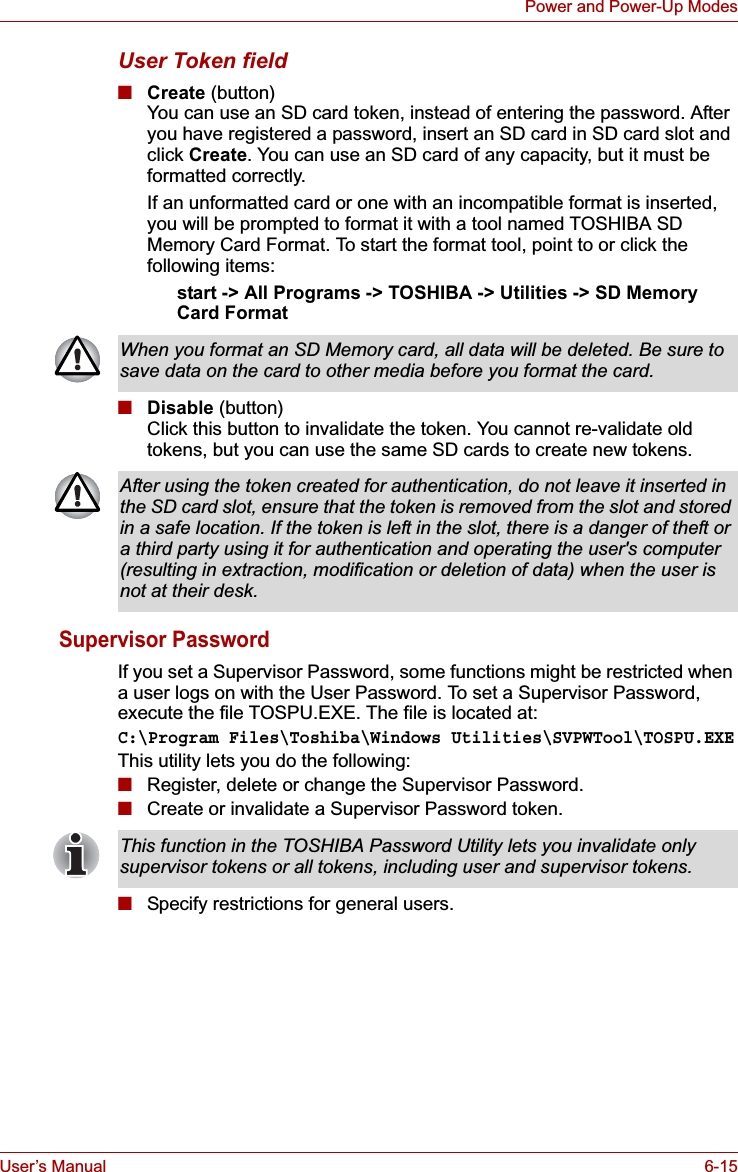
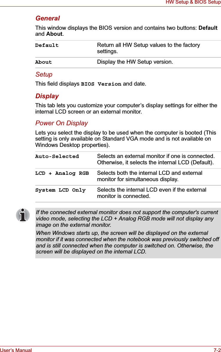
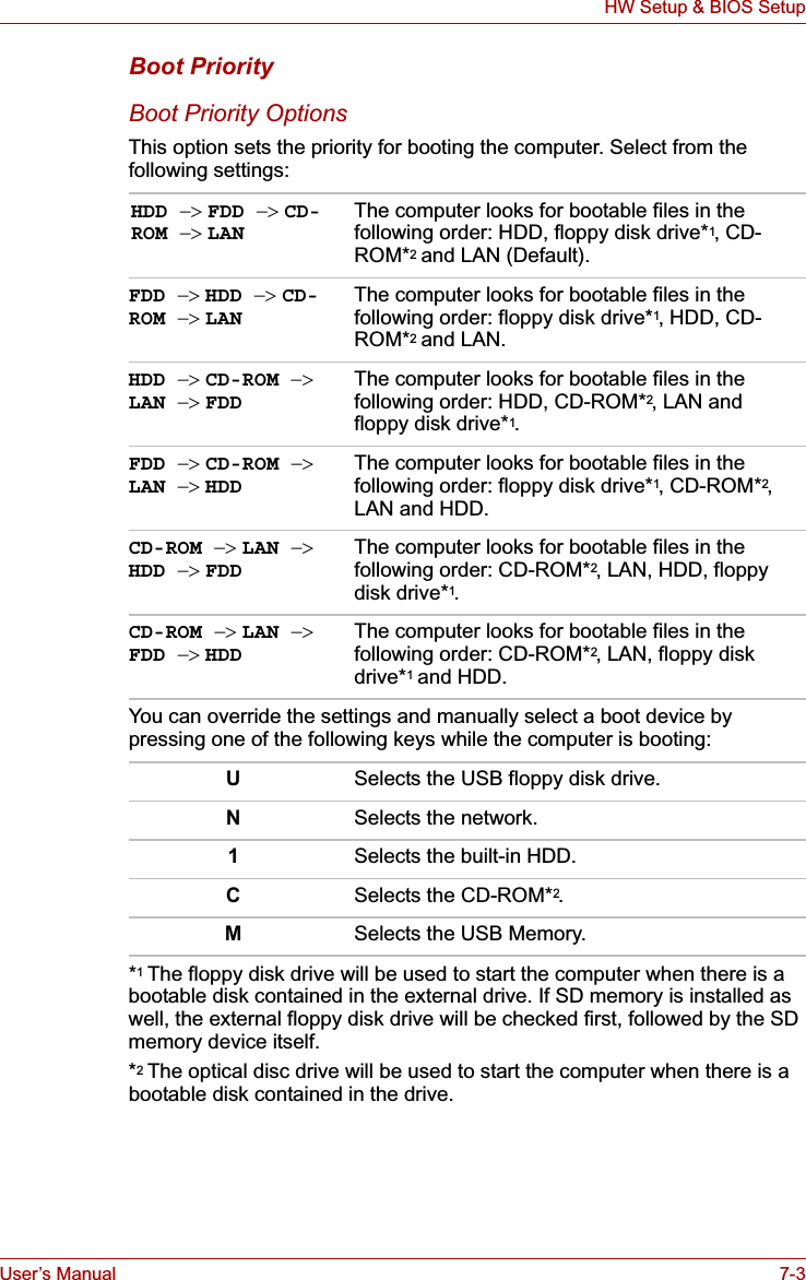
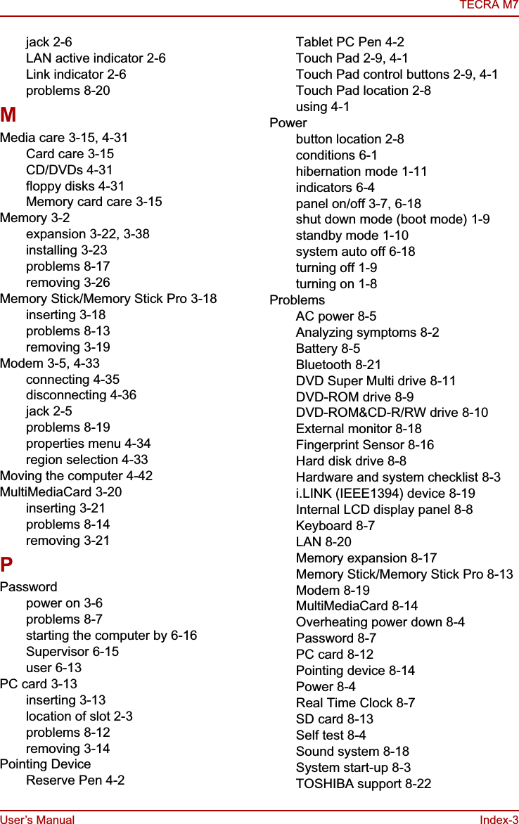
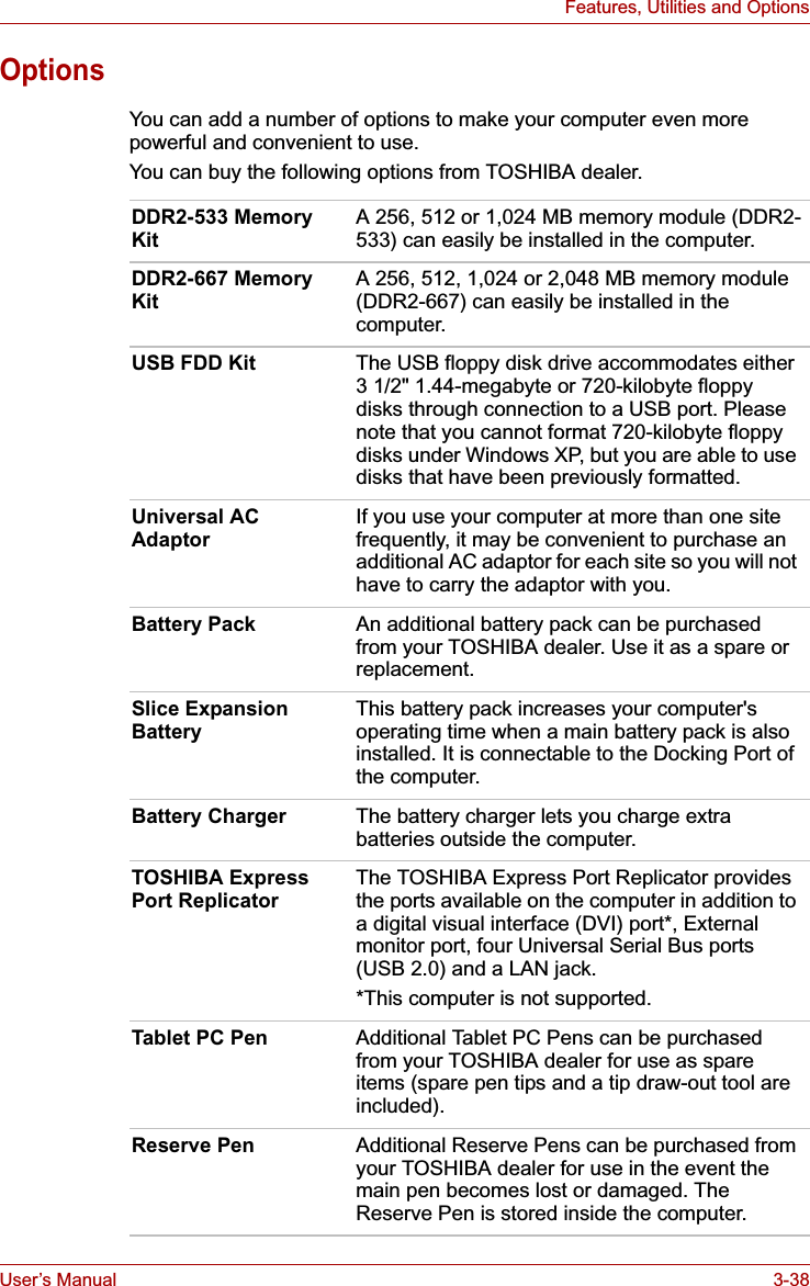
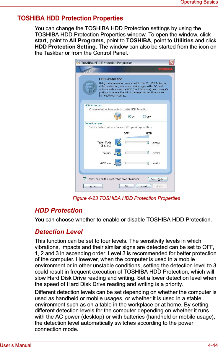
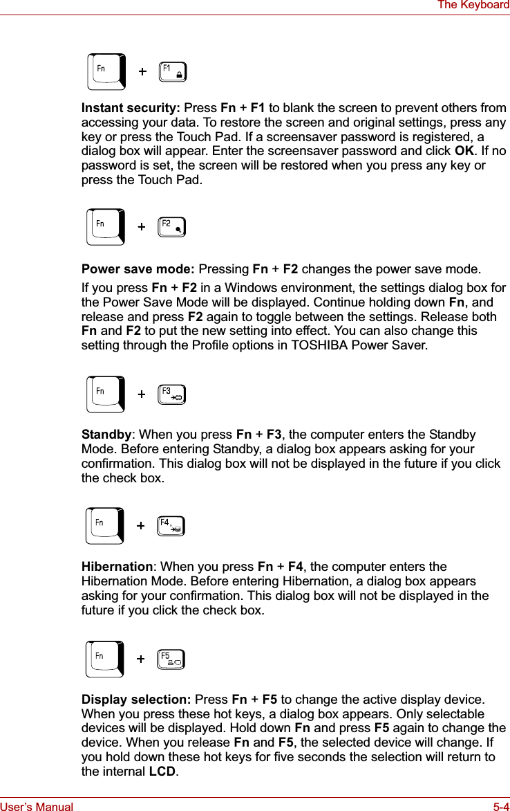
![User’s Manual 7-5HW Setup & BIOS SetupHDD Priority OptionsIf more than one HDD is installed in the computer, this option lets you set the priority for HDD detection. If the first detected HDD has a boot command, the system will boot from the HDD.Network Boot ProtocolThis feature sets the protocol to remotely boot from the network. [PXE] Sets PXE as the protocol (Default).[RPL] Sets RPL as the protocol.USB Memory BIOS Support TypeSet the type of the USB memory as a startup device.KeyboardWake-up on KeyboardWhen this feature is enabled and the computer is in Standby Mode, you can turn on the computer by pressing any key. It is effective only for the internal keyboard and only when the computer is in Standby Mode.Built-in HDD -> USB (Default)The priority is set as Built-in HDD -> USB.USB -> Built-in HDDThe priority is set as USB -> Built-in HDD.■If a boot command is not found on the first detected HDD, the system will not boot from the other HDD. It will search the next device in the boot priority for a boot command.■Some modules may not be displayed.Network Boot Protocol is not displayed for Gigabit Ethernet LAN.HDD Set the type of the USB memory to be equivalent to the HDD (Default).* Based on the [HDD] order in the [Boot Priority Options] item. The order with respect to the other HDD can be set in the [HDD Priority Options] item.FDD Set the type of the USB memory to be equivalent to the FDD.* Based on the [FDD] order in the [Boot Priority Options] item.Enabled Enables the Wake-up on Keyboard function.Disabled Disables the Wake-up on Keyboard function (Default).](https://usermanual.wiki/Dynabook/UPA3503WL.TECRA-M7-User-Manual/User-Guide-693494-Page-172.png)
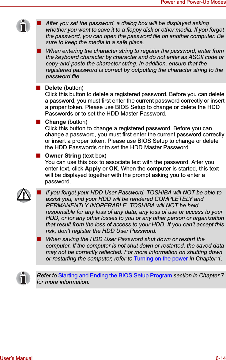
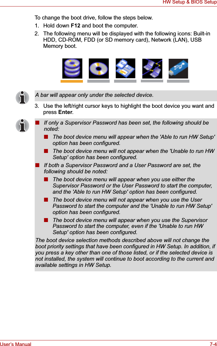
![User’s Manual 7-8HW Setup & BIOS SetupBIOS Setup ProgramSettings for some features are carried out in the BIOS setup program.Starting and Ending the BIOS Setup ProgramStarting the BIOS Setup Program1. Switch on your computer while pressing the Esc key. If "Password =" is displayed, enter either the Supervisor Password, if one is set, or the User Password and press the Enter key.Please refer to Chapter 6, the TOSHIBA Password Utility, for details about the User Password. The "Check system.Then press [F1] key." message is displayed.2. Press the F1 key.The BIOS setup program will start up.Ending the BIOS Setup ProgramSave the changes and end the program.1. Press the End Key.The "Are you sure? (Y/N) The changes you made will cause the system to reboot." message is displayed.2. Press the Y key.The configured settings are saved and the BIOS setup program ends.The computer may reboot depending on the settings that were modified.Notes before using the BIOS Setup■In most cases, changes to the system's configuration should be made within Windows by using applications such as TOSHIBA HW Setup, TOSHIBA Password Utility, TOSHIBA Power Saver, Windows Device Manager and so forth. If you make changes to the configuration through the BIOS setup program, please be aware that the configuration set through the Windows applications will take priority.■Changes to the settings within the BIOS setup program will not be erased even if the power supply is switched off and the main battery removed. However, if the built-in Real Time Clock (RTC) battery runs out of power, most of the settings will revert back to their default values. However, please note that the following items will not be affected in this instance:• Password • Hard Disk Drive Password • Security controllerPlease refer to the operating instructions displayed in the settings screen.](https://usermanual.wiki/Dynabook/UPA3503WL.TECRA-M7-User-Manual/User-Guide-693494-Page-175.png)
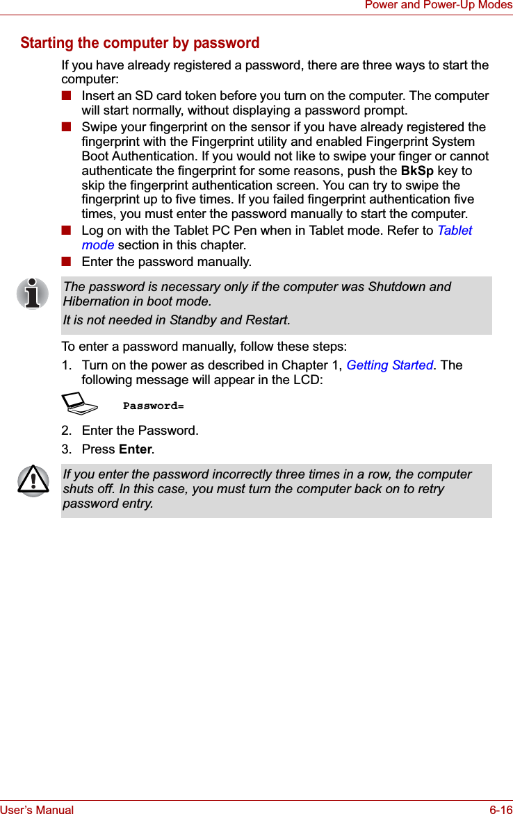
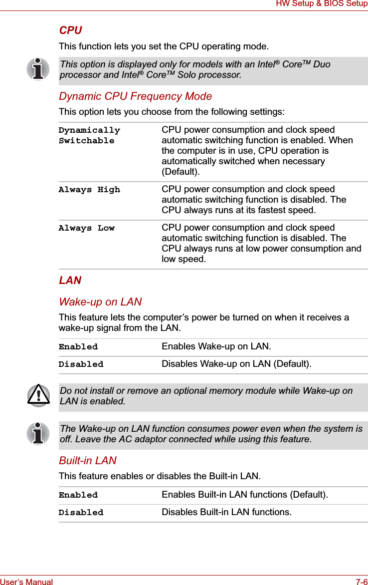
![User’s Manual 8-7TroubleshootingReal Time ClockPasswordKeyboard Keyboard problems can be caused by your setup configuration. For more information refer to Chapter 5, The Keyboard.Problem ProcedureThe following message is Displayed on the LCD screen:RTC battery is low or CMOS checksum is inconsistent. Press [F1] key to set Date/Time.The charge in the RTC battery has run out - you will need to set the date and time in the BIOS setup using the following steps:1. Press F1 key. BIOS setup will boot up.2. Set the date in System Date.3. Set the time in System Time.4. Press End key. Confirmation message will appear.5. Press Y key. BIOS setup will terminate and the computer will be rebooted.Problem ProcedureCannot enter password Refer to the TOSHIBA Password Utility section in Chapter 6, Power and Power-Up Modes.Problem ProcedureSome letter keys produce numbers Check that the numeric keypad overlay is not selected. Press Fn + F11 and try typing again.Output to screen is garbled Make sure the software you are using is not remapping the keyboard. Remapping involves reassigning the meaning of each key. See your software’s documentation.If you are still unable to use the keyboard, consult your dealer.](https://usermanual.wiki/Dynabook/UPA3503WL.TECRA-M7-User-Manual/User-Guide-693494-Page-185.png)
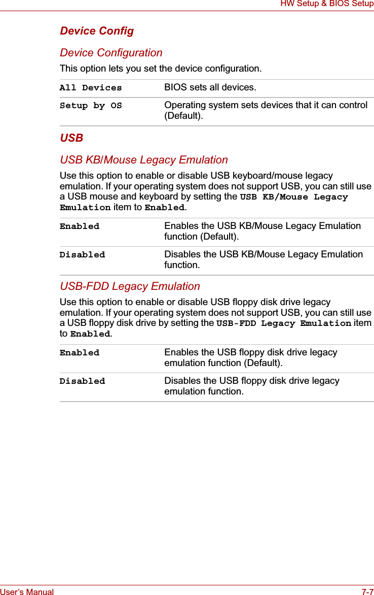
![User’s Manual J-3Legal FootnotesHard Disk Drive (HDD) Capacity*51 Gigabyte (GB) means 109 = 1,000,000,000 bytes using powers of 10. The computer operating system, however, reports storage capacity using powers of 2 for the definition of 1 GB = 230 = 1,073,741,824 bytes, and therefore shows less storage capacity. Available storage capacity will also be less if the product includes one or more pre-installed operating systems, such as Microsoft Windows and/or pre-installed software applications, or media content. Actual formatted capacity may vary.LCD*6Over a period of time, and depending on the usage of the computer, the brightness of the LCD screen will deteriorate. This is an intrinsic characteristic of LCD technology.Maximum brightness is only available when operating in AC power mode. The screen will dim when the computer is operated on battery power and you may not be able to increase the brightness of the screen.Graphics Processor Unit ("GPU")*7Graphics processor unit ("GPU") performance may vary depending on product model, design configuration, applications, power management settings and features utilized. GPU performance is only optimized when operating in AC power mode and may decrease considerably when operating in battery power mode.Wireless LAN*8The transmission speed over the wireless LAN and the distance over which wireless LAN can reach may vary depending on surrounding electromagnetic environment, obstacles, access point design and configuration, and client design and software/hardware configurations.[54Mbps is the theoretical maximum speed under the IEEE802.11 (a/b/g) standard.] The actual transmission speed will be lower than the theoretical maximum speed.Copy Protection*9Copy protection technology included in certain media may prevent or limit recording or viewing of the media.Images*10All images are simulated for purposes of illustration.](https://usermanual.wiki/Dynabook/UPA3503WL.TECRA-M7-User-Manual/User-Guide-693494-Page-244.png)