Dynabook UPA3539WL Wireless WiFi Link 4965AG User Manual Manual
Toshiba Corporation Wireless WiFi Link 4965AG Manual
UserManual.wiki
>
Dynabook
>
UPA3539WL User Manual
>
User Manual
Contents
1.
User Manual Addendum
2.
User Manual
User Manual
Navigation menu
Upload a User Manual
Namespaces
Wiki Guide
HTML
PDF
Info
Views
User Manual
Discussion / Help
Navigation

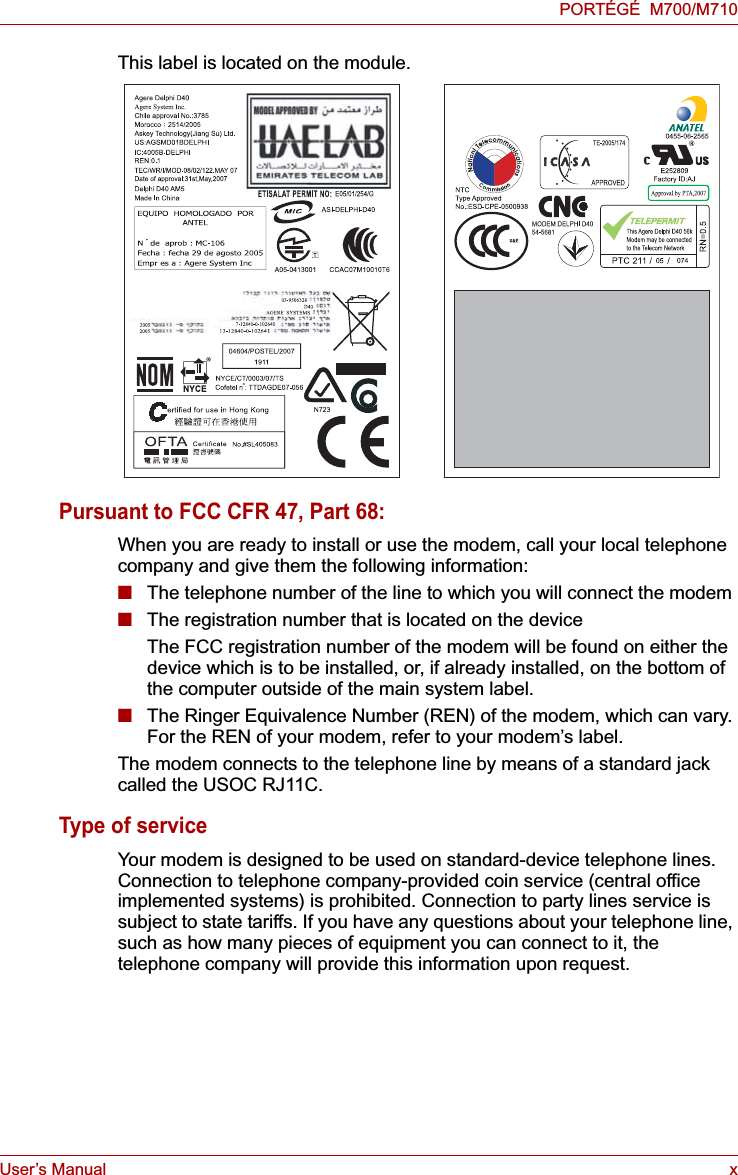
![User’s Manual viiiPORTÉGÉ M700/M710EU Conformity StatementThis product and - if applicable - the supplied accessories too are marked with "CE" and comply therefore with the applicable harmonized European standards listed under the Low Voltage Directive 2006/95/EC, the EMC Directive 2004/108/EC and/or R&TTE Directive 1999/5/EC.The complete official EU CE Declaration can be obtained on following internet page:http://epps.toshiba-teg.com/VCCI Class B InformationModem warning noticeConformity StatementThe equipment has been approved to [Commission Decision "CTR21"] for pan-European single terminal connection to the Public Switched Telephone Network (PSTN).However, due to differences between the individual PSTNs provided in different countries/regions the approval does not, of itself, give an unconditional assurance of successful operation on every PSTN network termination point.Responsible for CE-marking: TOSHIBA EUROPE GMBH, Hammfelddamm 8, 41460 Neuss, Germany.Manufacturer: Toshiba Corporation, 1-1 Shibaura 1-chome, Minato-ku, Tokyo, 105-8001, JapanThis information is applicable to the models equipped with a built-in modem.](https://usermanual.wiki/Dynabook/UPA3539WL.User-Manual/User-Guide-873201-Page-8.png)


![User’s Manual 3-40Hardware, Utilities and OptionsUSB Sleep and Charge functionYour computer can supply USB bus power (DC5V) to the USB port even when the power of the computer is turned OFF. "Power OFF" includes Sleep Mode, Hibernation Mode or shutdown state.This function can only be used for ports that support the USB Sleep and Charge function (hereinafter called "compatible ports").Compatible ports are USB ports that have the ( ) symbol icon.You can use the "USB Sleep and Charge function" to charge certain USB-compatible external devices such as mobile phones or portable digital music players.However, the "USB Sleep and Charge function" may not work with certain external devices even if they are compliant with the USB specification. In those cases, turn the power of the computer ON to charge the device.■The "USB Sleep and Charge function" only works for compatible ports.This function is disabled in the default setting. To enable it, you must change [Disabled] to [Enabled] in the BIOS Setup.Refer to the USB Sleep and Charge function section in Chapter 7, HW Setup & BIOS Setup.■When "USB Sleep and Charge function" is set to [Enabled] in BIOS Setup, USB bus power (DC5V) will be supplied to compatible ports even when the power of the computer is turned OFF.USB bus power (DC5V) is similarly supplied to the external devices which are connected to the compatible ports. However, some external devices cannot be charged solely by supplying USB bus power (DC5V).As for the specifications of the external devices, please contact the device manufacturer or check the specifications of the external devices thoroughly before use.■Using the USB sleep and charge function to charge external devices will take longer than charging the devices with their own chargers.■If external devices are connected to compatible ports when the AC adaptor is not connected to the computer, the battery of the computer will be depleted even when the power of the computer is turned OFF.As such, we recommend that you connect the AC adaptor to the computer when using the USB sleep and charge function.■External devices connected to the USB bus power (DC5V) function that interfaces with the power ON/OFF of the computer may always be in an operational state.■When there is a current overflow of the external devices connected to the compatible ports, USB bus power (DC5V) supply may be stopped for safety reasons.Metal paper clips or hair pins/clips will generate heat if they come into contact with USB ports. Do not allow USB ports to come into contact with metal products, for example when carrying the computer in your bag.](https://usermanual.wiki/Dynabook/UPA3539WL.User-Manual/User-Guide-873201-Page-94.png)
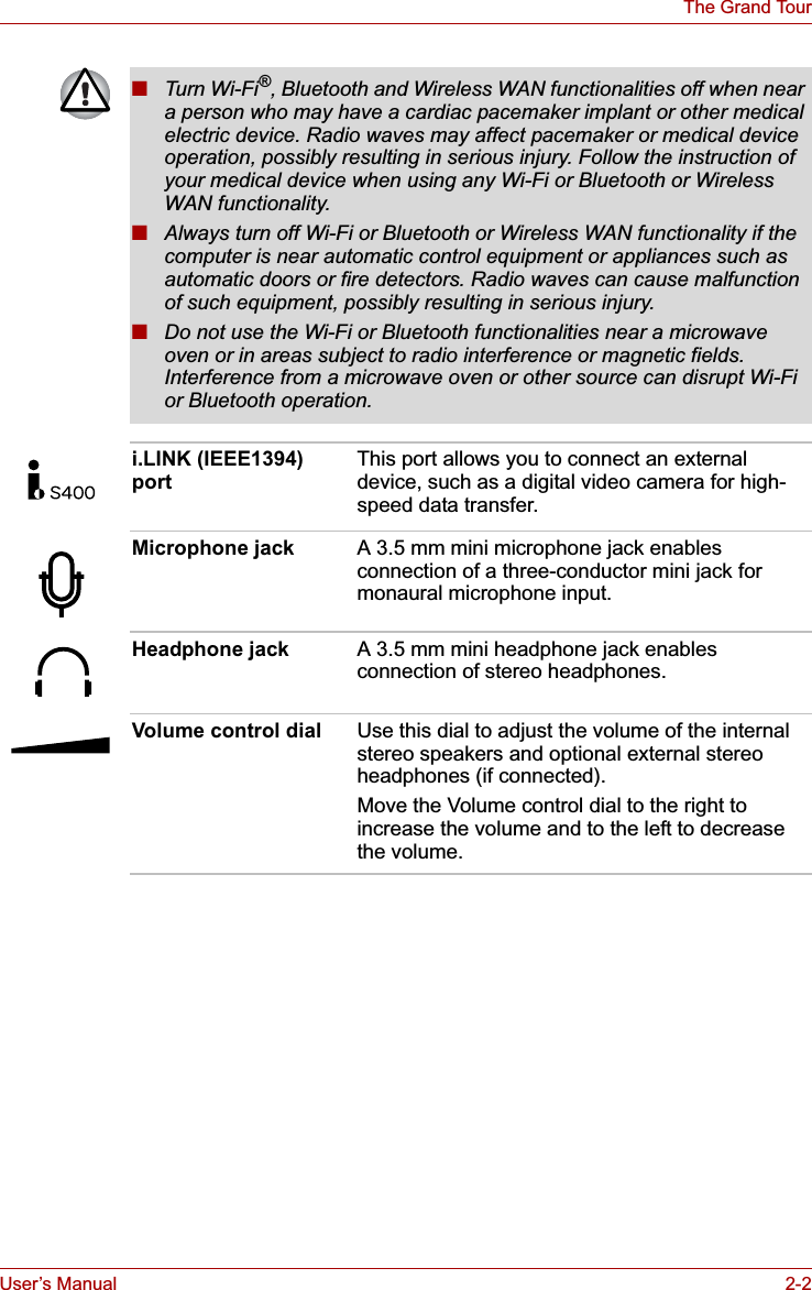
![User’s Manual 3-41Hardware, Utilities and OptionsUSB WakeUp functionThis function restores the computer from Sleep Mode depending on the external devices connected to the USB ports.The "USB WakeUp function" operates under Windows Vista® OS and it works for all USB ports.i.LINK (IEEE1394)i.LINK (IEEE1394) is used for high-speed data transfer for a range of compatible devices such as:■Digital video cameras■Hard disk drives■MO drives■Writable optical disc drivesPrecautions■Make a back-up of your data before transferring it to the computer. There is a possibility that the original data will be damaged. There is a particular risk that some frames will be deleted in the case of digital video transfer. TOSHIBA assumes no liability for such loss of data.■Do not transfer data in areas where static electricity is easily generated or in areas subjected to electronic noise. Data can be destroyed.■If you are transferring data through an IEEE1394 hub, do not connect or disconnect other devices from the hub during data transfer. There is a likelihood that data will be damaged. Connect all devices to the hub before you turn on the computer’s power.■You may not use any copyrighted video or music data copied from a video camera except for your personal enjoyment.■"USB WakeUp function" will supply USB bus power (DC5V) to all USB ports ,including compatible ports, even when the computer is in Sleep Mode.USB bus power (DC5V) will not be supplied if the computer is in Hibernation Mode or shutdown state.■When "USB Sleep and Charge function" is set to [Enabled] in BIOS Setup, the "USB WakeUp function" does not work for compatible ports. The WakeUp setting (function to allow the WakeUp) check box will be displayed on the Device Manager. You can change the settings but the USB WakeUp function will not work. For example, if a mouse or USB keyboard is connected to a compatible port, moving the mouse/keyboard will not "wakeup" the computer.In that case, attach the mouse or keyboard to an USB port that does not have the USB Sleep and Charge function-compatible icon ( ).i.LINK uses a four-pin connector, which does not carry any electric current. External devices will need their own power supply to operate.](https://usermanual.wiki/Dynabook/UPA3539WL.User-Manual/User-Guide-873201-Page-95.png)
![User’s Manual 4-23Operating BasicsFingerprint Pre-OS AuthenticationGeneralThe fingerprint authentication system can be used to replace the keyboard based password authentication system that is used when the computer is turned on.If you do not want to use the fingerprint authentication system for password authentication while booting up the computer, instead you prefer using the keyboard entry method, simply press the BACK SPACE key or the ESC/Rotation button when the Fingerprint Pre-OS Authentication screen is displayed.Using this process will switch the password input screen across to the keyboard based entry screen.How to Enable Fingerprint Pre-OS Authentication SettingsIt is necessary to first enroll your fingerprint with the Fingerprint Application prior to enabling and configuring the Fingerprint Pre-OS Authentication System. You should check that your fingerprint is enrolled before configuring the settings (please refer to the Manual for Fingerprint Registration/Enrollment for further instructions).1. To run this program, click Start -> All Programs -> TrueSuite Access Manager -> Fingerprint Application with Admin.2. UserAccountControl screen is displayed, click the Allow button.This setting can only be changed if the currently logged in user has administrator privileges.3. Swipe a registered finger on the fingerprint sensor.4. Click the Setting menu at the TrueSuiteAccessManager screen.5. Administrator Setting screen is displayed, check the "Enable Pre-OS Fingerprint Authentication" check box and then click OK.6. Click the Exit button at the TrueSuiteAccessManager screen.■You must ensure that you use the TOSHIBA Password Utility to register a User Password before using the Fingerprint Pre-OS Authentication and its extended function to allow fingerprints to be used to access the computer when it is turned on.■If the fingerprint authentication process fails five times, a preset time limit is exceeded, or you press the BACK SPACE key, [Password =] will be displayed on the screen and you will have to enter either the User Password or Supervisor Password manually in order to start the computer.■When swiping your finger, please ensure that you do it slowly and at a constant speed. If you find that this does not improve the authentication rate, you should try to adjust the speed at which the finger is swiped.■If there are any changes in the environment or settings related to authorization, you will be required to provide authorization information such as a User Password (and, if applicable, the HDD(Hard Disk Drive) password).](https://usermanual.wiki/Dynabook/UPA3539WL.User-Manual/User-Guide-873201-Page-123.png)
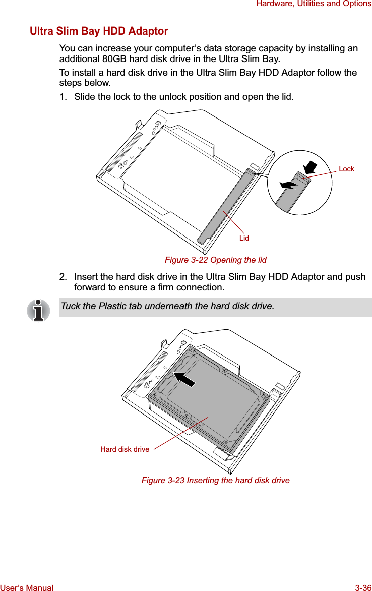
![User’s Manual 4-26Operating BasicsChanging Ultra Slim Bay modulesThis section explains how to change modules in the Ultra Slim Bay. The illustrations show replacement of the optical disc drive with the Ultra Slim Bay HDD Adaptor.Removing a moduleTo remove the optical disc drive, follow the steps as described below:1. Save your work.2. Turn the computer's power off - ensure that the Power indicator is off.3. Remove all cables and peripherals that are connected to the computer.4. Close the display panel.5. Turn the computer upside down and remove the battery pack (refer to Replacing the battery pack section in Chapter 6, Power and Power-Up Modes, if required).6. Remove the Ultra Slim Bay lock screw from the Lock position.7. Set the Ultra Slim Bay lock screw in the Unlock position.■Do not point the web camera directly at the sun.■Do not touch or press strongly on the web camera lens. Doing so may reduce image quality. Use an eyeglass cleaner (cleaner cloth) or other soft cloth to clean the lens if it becomes dirty.■Setting the [Size] to more than "800x600" will cause a larger amount of data to be written to the hard disk drive and may interfere with smooth recording.■When recording in dimly lit environments, the following procedure can be used to select "Night Mode" which allows for brighter images with less noise.1. Click the Properties button on the [Web Camera] menu.2. Check Night Mode on the [Options] tab.3. Click the OK button.The number of frames per second is lowered when "video recording" in "Night Mode". This may result in the playback of the recorded video file seeming unsmooth.To avoid injury, do not put your hand into the Ultra Slim Bay slot.Always make sure the display panel is closed in Laptop mode before turning the computer upside down.Wait for all disk indicators to go out before you turn over the computer and do not lay the computer down gently. Shock can damage the HDD or other components.](https://usermanual.wiki/Dynabook/UPA3539WL.User-Manual/User-Guide-873201-Page-126.png)

![User’s Manual 6-6Power and Power-Up ModesReal Time Clock (RTC) batteryThe Real Time Clock (RTC) battery provides power for the internal real time clock and calendar function and also maintains the system configuration while the computer is turned off. If the RTC battery becomes completely discharged, the system will lose this information and the real time clock and calendar will stop working - in this instance the following message will be displayed when you turn on the power:S**** RTC battery is low or CMOS checksum is inconsistent **** Press [F1] key to set Date/Time. You can change the Real Time Clock settings by turning the computer on while pressing the ESC key and then the F1 key when prompted. Please refer to Chapter 8 Troubleshooting for further information.Care and use of the battery packThis section provides the important safety precautions in order to handle your battery pack properly.Refer to the enclosed Instruction Manual for Safety and Comfort for detailed precautions and handling instructions.The RTC battery does not charge while the computer is turned off even if the AC adaptor is attached.■Make sure the battery is securely installed in the computer before attempting to charge the battery pack. Improper installation could generate smoke or fire, or cause the battery pack to rupture.■Keep the battery pack out of reach of infants and children. It can cause injury.■The battery pack and Slice Expansion Battery are lithium ion battery, which can explode if not replaced, used, handled or disposed of properly. Dispose of the battery as required by local ordinances or regulations. Use only batteries recommended by TOSHIBA as replacements.■The computer's RTC battery is a Ni-MH battery and should be replaced only by your dealer or by a TOSHIBA service representative. The battery can explode if not properly replaced, used, handled or disposed. Dispose of the battery as required by local ordinances or regulations. ■Charge the battery pack only in an ambient temperature between 5 and 35 degrees Celsius. Otherwise, the electrolyte solution might leak, battery pack performance might deteriorate and the battery life might be shortened.■Never install or remove the battery pack without first turning off the power and disconnecting the AC adaptor. Never remove the battery pack while the computer is in Sleep Mode. Data could be lost.](https://usermanual.wiki/Dynabook/UPA3539WL.User-Manual/User-Guide-873201-Page-168.png)
![User’s Manual 7-8HW Setup & BIOS SetupBIOS Setup ProgramSettings for some features are carried out in the BIOS setup program.Starting and Ending the BIOS Setup ProgramStarting the BIOS Setup Program1. Turn on the computer while pressing the ESC key - if the Password =prompt is displayed, enter either the Supervisor Password, if one is set, or the User Password and press the ENTER key. Please refer to Chapter 6, the TOSHIBA Password Utility for further details about the User Password.2. At the Check system. Then press [F1] key. prompt, press the F1 key - the BIOS setup application will start up.Ending the BIOS Setup ProgramIn order to save the changes you have made and end the BIOS setup application, follow the steps as detailed below:1. Press the END key - this will cause the Are you sure? (Y/N). The changes you made will cause the system to reboot.prompt to be displayed at the bottom of the screen.2. Press the Y key - this will save the configuration changes and end the BIOS setup application, automatically restarting the computer.Notes Before Using the BIOS Setup Application■In most cases, changes to the system's configuration should be made within Windows by using applications such as TOSHIBA HW Setup,TOSHIBA Password Utility,Windows Device Manager and so forth. If you make changes to the configuration through the BIOS setup program, please be aware that the configuration set through the Windows applications will take priority.■Changes to the settings within the BIOS setup program will not be erased even if the power supply is turned off and the main battery removed. However, if the built-in Real Time Clock (RTC) battery runs out of power, most of the settings will revert back to their default values. However, please note that the following items will not be affected in this instance:• Password• Hard Disk Drive Password• Security Controller• Fingerprint patternsPlease refer to the operating instructions displayed in the settings screen.](https://usermanual.wiki/Dynabook/UPA3539WL.User-Manual/User-Guide-873201-Page-189.png)
![User’s Manual 7-13HW Setup & BIOS SetupSATA Controller ModeThis feature sets the SATA Controller Mode.USB Sleep and Charge functionThis section describes the settings for "USB Sleep and Charge function". For more information, please refer to the USB Sleep and Charge functionsection in Chapter 3, Hardware, Utilities and Options.The default setting in BIOS Setup is [Disabled]. Changing the setting to [Enabled] enables the use of this function. There are two modes, Mode-1 and Mode-2 in [Enabled]. For normal use, set the setting to Mode-1. The SATA Controller Mode is supported with some models.AHCI Sets AHCI which is the mode for Windows Vista®(Default).Compatibility Sets the mode for legacy OS. Use this mode when the driver corresponding to AHCI is not used.If the function does not work with Mode-1 setting, change it to Mode-2. Some external devices may not be able to use this function in either mode. When this happens, change the setting to [Disabled]. Enabled (Mode-1) Enables USB Sleep and Charge function.Enabled (Mode-2) Enables USB Sleep and Charge function.Disabled Disables USB Sleep and Charge function (Default).](https://usermanual.wiki/Dynabook/UPA3539WL.User-Manual/User-Guide-873201-Page-194.png)
![User’s Manual 8-7TroubleshootingReal Time ClockPasswordKeyboardKeyboard problems can be caused by the setup and configuration of the computer - please refer to Chapter 5, The Keyboard for further information.Problem ProcedureThe following message is Displayed on the screen:RTC battery is low or CMOS checksum is inconsistent. Press [F1] key to set Date/Time.The charge in the Real Time Clock (RTC) battery has run out - you will need to set the date and time in the BIOS setup application by using the following steps:1. Press the F1 key - the BIOS setup application will load.2. Set the date in the System Date field.3. Set the time in the System Time field.4. Press the END key - a confirmation message will be displayed.5. Press the Y key - the BIOS setup application will end and the computer will restart.Problem ProcedureCannot enter password Please refer to the TOSHIBA Password Utilitysection in Chapter 6, Power and Power-Up Modes for further information.Problem ProcedureSome letter keys produce numbers Check that the numeric keypad overlay is not activated - press the FN + F11 hot key and try typing again.Output to screen is garbled Please refer to your software's documentation to ensure that its is not remapping the keyboard in any way (remapping involves changing or reassigning the function of each key).If you are still unable to use the keyboard, you should contact your reseller, dealer or service provider.](https://usermanual.wiki/Dynabook/UPA3539WL.User-Manual/User-Guide-873201-Page-201.png)
![User’s Manual 8-17TroubleshootingUSB deviceIn addition to the information in this section, please also refer to the documentation supplied with your USB device.USB Sleep and Charge functionProblem ProcedureUSB device does not workRemove the USB device from the computer and then reconnect it to a free port it in order to ensure it is firmly attached.Ensure that any required USB device drivers are properly installed - to achieve this you should refer to both the device documentation and the operating system documentation.If you are using an operating system that does not support USB, you are still able to use a USB mouse and/or USB keyboard by setting the USBKB/Mouse Emulation option within the TOSHIBA HW Setup utility to Enabled.If you are still unable to resolve the problem, contact your reseller, dealer or service provider.Problem ProcedureI cannot use the "USB Sleep and Charge function".The setting of "USB Sleep and Charge function" may be [Disabled]. Change the setting to [Enabled] in the BIOS Setup.When there is a current overflow of the external device connected to the compatible port, USB bus power (DC5V) supply may be stopped for safety reasons. When this happens, disconnect an external device if some external devices are connected. After that, turn the power of the computer ON/OFF to restore the function. If this function can not be still used even if only one external device is connected, stop using the external device because its current is over the acceptable value of this computer.](https://usermanual.wiki/Dynabook/UPA3539WL.User-Manual/User-Guide-873201-Page-211.png)
![User’s Manual 8-18TroubleshootingProblem ProcedureSome external devices may not be able to use the "USB Sleep and Charge function". In this case, please try one or more of the following methods. ■Change a mode setting of [Enabled] by the BIOS Setup.■Turn OFF the computer while external devices are connected.■Connect external devices after turning OFF of the computer.If this function can not be still used, change the setting to [Disabled] in the BIOS Setup and stop using this function.The battery depletes quickly even when I turned OFF the power of the computer. When "USB Sleep and Charge function" is set to [Enabled] in the BIOS Setup, USB bus power (DC5V) will be supplied to the external device connected to the compatible port. If external device is connected to the compatible port when the AC adaptor is not connected to the computer, the battery of the computer will be depleted even when the power of the computer is turned OFF.Connect the AC adaptor to the computer or change the "USB Sleep and Charge function" setting to [Disabled] in the BIOS Setup.Instead use an USB port that does not have the USB Sleep and Charge function-compatible icon ( ).External devices connected to the compatible ports do not work when connected to a compatible port. Some external devices may not work when connected to a compatible port when the "USB Sleep and Charge function" is [Enabled] in the BIOS Setup.Reconnect the external device after turning ON the computer.If the external device still does not work, connect device to an USB port that does not have the USB Sleep and Charge function-compatible icon ( ) or change the "USB Sleep and Charge function" setting to [Disabled] in the BIOS Setup.](https://usermanual.wiki/Dynabook/UPA3539WL.User-Manual/User-Guide-873201-Page-212.png)
![User’s Manual 8-19TroubleshootingAdditional memory modulePlease also refer to Chapter 3, Hardware, Utilities and Options, for further information on installing and removing memory modules.Problem ProcedureThe "USB WakeUp function" does not work.When "USB Sleep and Charge function" is set to [Enabled] in the BIOS Setup, the "USB WakeUp function" does not work for ports that support the USB Sleep and Charge function.In that case, use an USB port that does not have the USB Sleep and Charge function-compatible icon ( ) or change the "USB Sleep and Charge function" setting to [Disabled] in the BIOS Setup.Problem ProcedureIf there is a memory malfunction, the Powerindicator will repeatedly flash (on for 0.5 seconds, off for 0.5 seconds) in the following patterns;If there is an error in only slot A or no memory module is inserted in Slot A: orange twice, then green once.If there is an error in Slot B: orange once, then green twice.If there are errors in both Slot A and Slot B: orange twice, then green twice.In the event the Power indicator flashes when the computer is turned on, you should first check that the installed memory module(s) are compatible with the computer. If there is an error with a compatible memory module, there is a possibility the memory module is damaged.If you determine that an incompatible module has been installed, you should follow the steps as detailed below:1. Turn off the computer.2. Disconnect the AC adaptor and all peripheral devices.3. Remove the battery pack.4. Remove the incompatible memory module.5. Install the battery and/or connect the AC adaptor.6. Turn on the computer.If you are still unable to resolve the problem, contact your reseller, dealer or service provider.An error will occur if a memory module is inserted into Slot B while no memory module is inserted in Slot A.Remove the memory module from Slot B and insert it into Slot A.](https://usermanual.wiki/Dynabook/UPA3539WL.User-Manual/User-Guide-873201-Page-213.png)