Dynabook UTDPW01WL Wireless LAN Module Unit User Manual
Toshiba Corporation Wireless LAN Module Unit Users Manual
Dynabook >
Users manual

Wireless LAN Module Unit
User’s Manual
Model : TDPWLAN01
Prior to using wireless LAN module unit, please take the time to read through this
user’s manual to ensure correct usage of the unit.
This wireless LAN module unit offers an additional feature of wireless LAN supporting
IEEE802.11g/b by embedding in a projector and controlled by a control unit which is
connected to the unit with FFC cable.
This wireless LAN module unit is a built-in device designed to be exclusively used for
projectors. Do not use for any other purposes.
This wireless LAN module unit is not commercially available to regular users for use.
IMPORTANT SAFETY PRECAUTIONS
● Please read and observe all warnings and instructions given in this User’s
Manual.
■ If you notice smoke or a strange smell coming from the unit, turn off the power.
■ Do not attempt to repair, remodel or disassemble this product.
■ Do not use near water.
■ Do not use near people with heart pacemakers
■ Do not use near electronic medical equipment, or in hospitals or other
Medical institutions
■ Do not use inside aircraft or in places where the wireless LAN module could
interfere with electromagnetic signals.
The electromagnetic interference could cause a malfunction, resulting in an
accident.
■ If the use of a wireless LAN module interferes with another device’s
electromagnetic signals, cease use immediately.
The electromagnetic interference could cause a malfunction, resulting in an
accident.
1

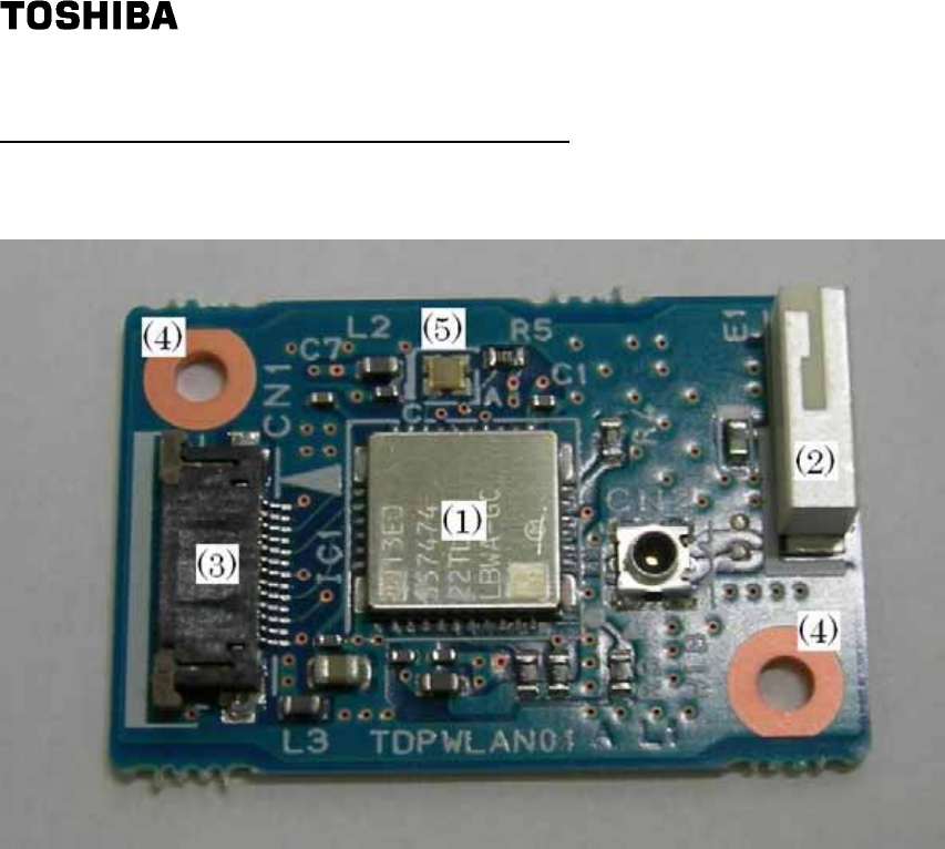
Appearance and Names of each part
Figure 1.
(1). Wireless LAN Module
(2). Chip Antenna
(3). 13-pin connector for FFC cable
(4). Hole for Screw
(5). LED
2

Specification
Interface : SDIO FFC13-pin cable supported
Wireless LAN : IEEE802.11g/b
Operating frequency band : 2.4 GHz
Transmission speed : 54, 48, 36, 24, 18, 12, 9, 6 (Mbps)(IEEE802.11g)
11,5.5, 2,1(Mbps)(IEEE802.11b)
Channel : 1 to 11 channel(See Table 1)
External dimensions : 32 x 21 x 5(typ.)mm
Weight : 2.8 g
Consumption current : 3.3V(200(typ.)mA) 1.8V(200(typ.)mA)
Conditions for usage environment : Temp: 0 to 40 degrees C;
relative humidity: 30% to 70%
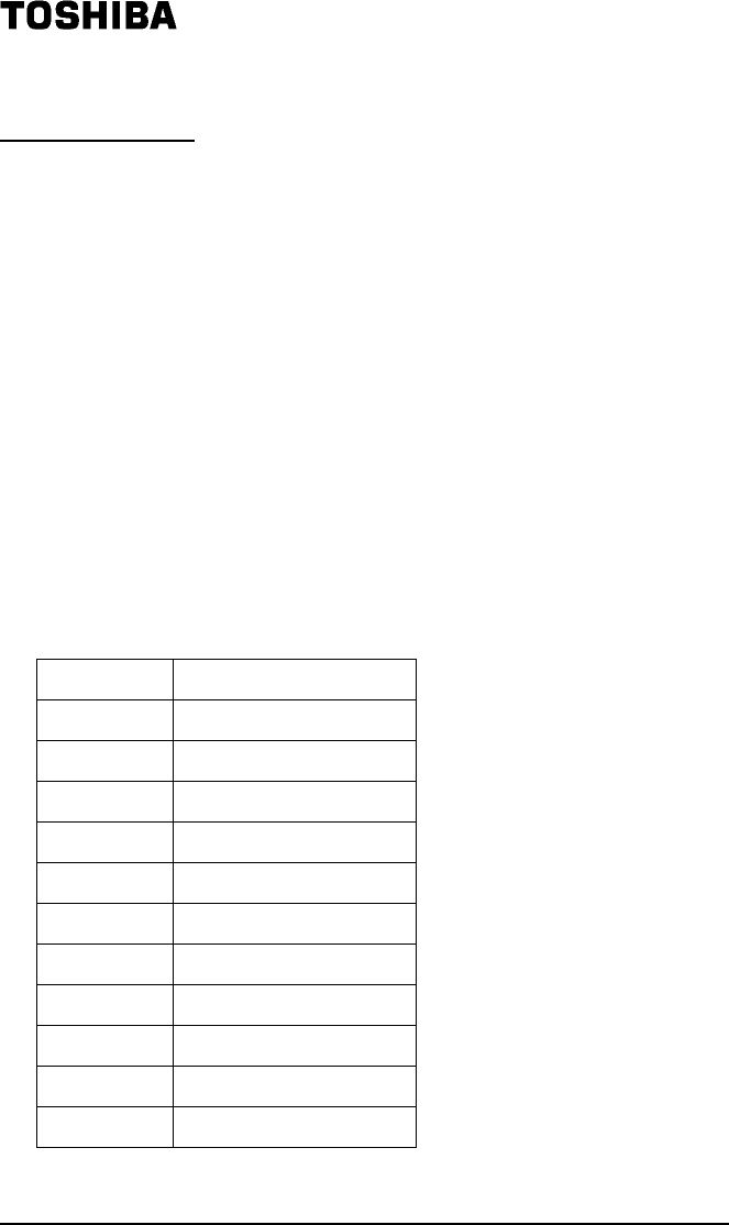
Table 1.
Channel Center Frequency
1 2412MHz
2 2417MHz
3 2422MHz
4 2427MHz
5 2432MHz
6 2437MHz
7 2442MHz
8 2447MHz
9 2452MHz
10 2457MHz
11 2462MHz
Pin assignment of 13-pin connector for FFC cable
1. SD-CLK
2. GND
3. SD-CMD
4. GND
5. SD-DAT0
6. GND
7. SD-DAT1
8. GND
9. SD-DAT2
3

10. 3.3V
11. SD-DAT3
12. 1.8V
13. RESET
Installation
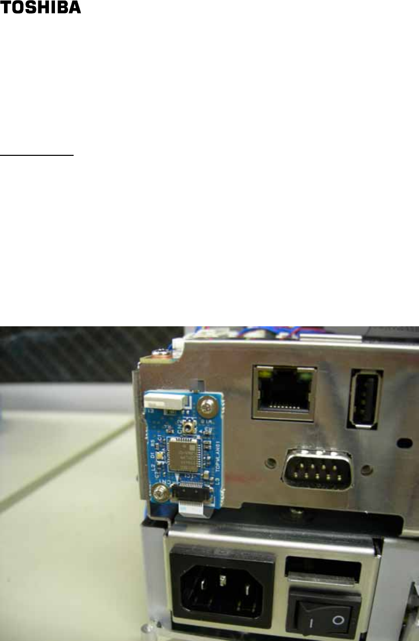
Figure 2 shows an example of installation.
1. Place the rear side of the unit on the electrically-grounded metal surface and fix
with two screws as shown in Figure 2.
2. Plug the FFC cable in 13-pin connector for FFC cable.
■ Notes
Do not place any objects which do not conduct electric waves outside the chip
antenna.
Figure 2.
This device contains WLAN module and FCC ID: CJ6UTDPW01WL / IC ID: 248H-DTDPW01W
4
FCC Compliance Statement:
This device complies with part 15 of the FCC Rules. Operation is subject to
the following two conditions:
(1) This device may not cause harmful interference, and
(2) This device must accept any interference received, including interference
that may cause undesired operation.
This product has been tested and complies with the specifications for a Class
B digital device, pursuant to Part 15 of the FCC Rules. These limits are
designed to provide reasonable protection against harmful interference in a
residential installation. This equipment generates, uses, and can radiate
radio frequency energy and, if not nstalled and used according to the
instructions, may cause harmful interference to radio communications.
However, there is no guarantee that interference will not occur in a particular
installation. If this equipment does cause harmful interference to radio or
television reception, which is found by turning the equipment off and on, the
user is encouraged to try to correct the interference by one or more of the
following measures:
-Reorient or relocate the receiving antenna
-Increase the separation between the equipment or devices
-Connect the equipment to an outlet other than the receiver's
-Consult a dealer or an experienced radio/TV technician for assistance
Caution: Any changes or modifications not expressly approved by the party
responsible for compliance could void the user's authority to operate the
equipment.
RF exposure warning:This equipment must be installed and operated in
accordance with provided instructions and the antenna(s) used for this
transmitter must be installed to provide a separation distance of at least 20 cm
from all persons and must not be co-located or operating in conjunction with
any other antenna or transmitter. End-users and installers must be provide
with antenna installation instructions and transmitter operating conditions for
satisfying RF exposure compliance.