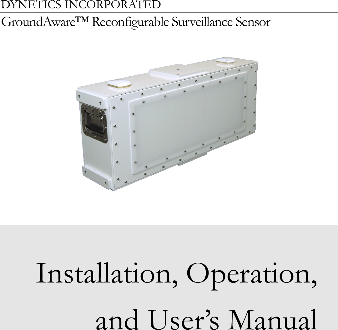
Dynetics 001-10018266 GROUND RADAR User Manual
Dynetics, Inc. GROUND RADAR
UserManual.wiki
>
Dynetics
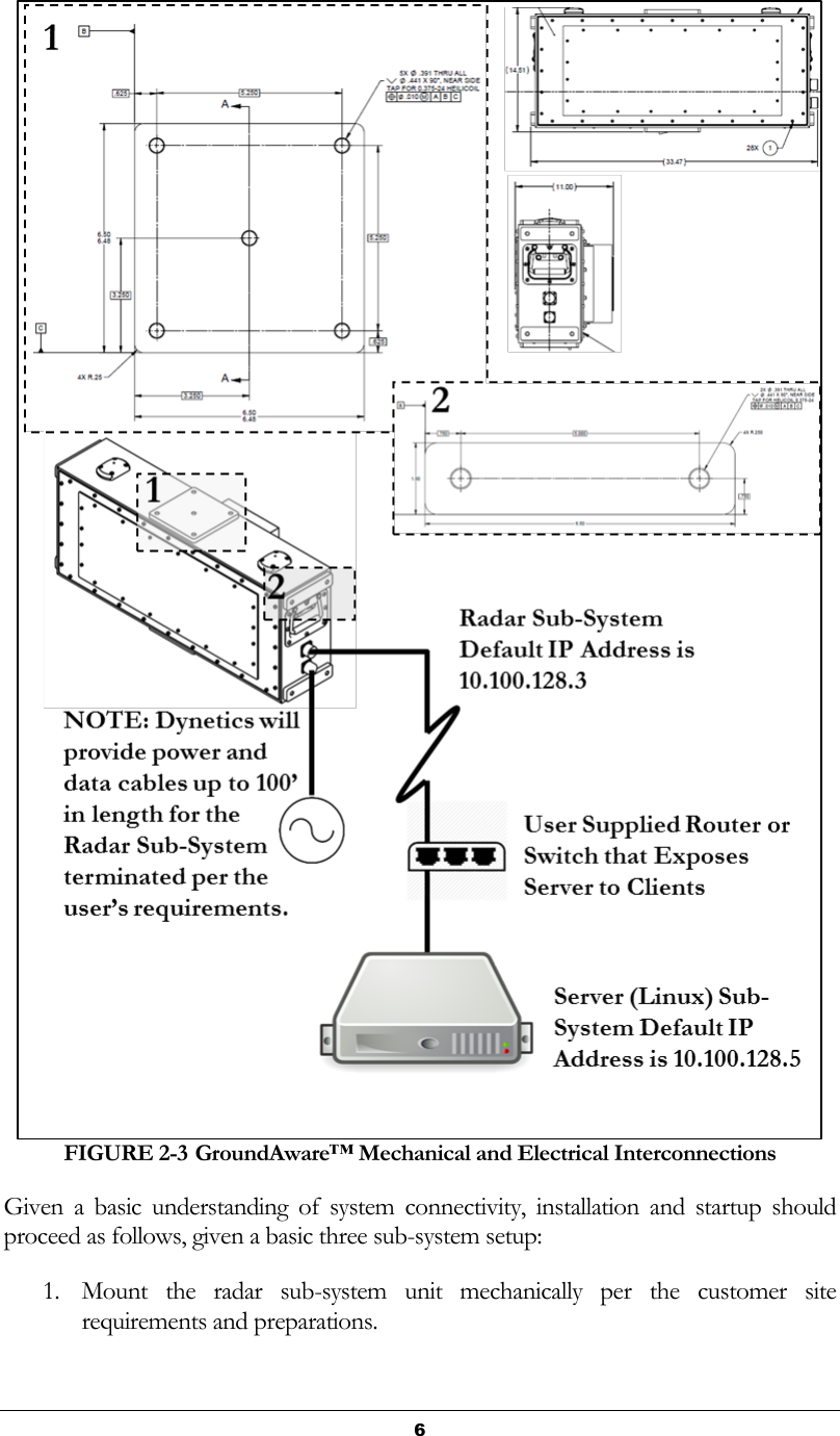
>
001 10018266 User Manual
User Manual
Navigation menu
Upload a User Manual
Namespaces
Wiki Guide
HTML
PDF
Info
Views
User Manual
Discussion / Help
Navigation