Dyson Technology WIFIAMFA001 Radio Module User Manual Dyson Wireless Module Installation Guide v6
Dyson Ltd Radio Module Dyson Wireless Module Installation Guide v6
User Manual

Document Number 001
DOC
–
Wifi Module Installation
Guide
Revision
006
© Dyson Technology Limited 2015
1
DYSON CONFIDENTIAL INFORMATION
This document and the copyright in it are the sole property of Dyson Technology Limited.
The document and its contents are confidential and may not be reproduced, disclosed or
used without the prior written consent of Dyson Technology Limited. This document is also
protected by unpublished copyright. © Dyson Technology Limited 2015
Dyson Technology Limited, Tetbury Hill, Malmesbury, Wiltshire, SN16 0RP

Document Number 001
DOC
–
Wifi Module Installation
Guide
Revision
006
© Dyson Technology Limited 2015
2
1. Installation of the Radio Module
The device WIFIAMFA001 is only used in Dyson products. This module is factory mounted in the Dyson
Environmental Products.
This module is not supplied to the end user on its own and the WIFIAMFA001 module will only be
installed or replace on the end products by Dyson Engineers. As such a simple installation guide is given
for reference only.
2. Compliance Statement
FCC (Federal Communications Commission) statements
This device complies with Part 15 of the FCC Rules. Operation is subject to the following two conditions:
1) The device may not cause harmful interference, and
2) The device Module must accept any interference received, including interference that may cause
undesired operation.
This device complies with FCC RF radiation exposure limits set forth for an uncontrolled environment. The
antenna used for this transmitter must be installed to provide a separation distance of at least 20 cm
from all persons and must not be co-located or operating in conjunction with any other antenna or
transmitter.
Important Note: This equipment has been tested and found to comply with the limits for a Class B digital
device, pursuant to Part 15 of the FCC Rules. These limits are designed to provide reasonable protection
against harmful interference in a residential installation. This equipment generates, uses and can radiate
radio frequency energy and, if not installed and used in accordance with the instructions, may cause
harmful interference to radio communications. However, there is no guarantee that interference will not
occur in a particular installation.
This transmitter must not be co-located or operating in conjunction with any other antennas or
transmitters.
It is the responsibility of the host device manufacturer to ensure continued compliance with FCC rule part
15B once the module has been installed in the host device.
Changes or modifications not expressly approved by the party responsible for compliance could void the
user's authority to operate the equipment.
The concerned end product must be labelled to say
“Contains FCC ID: QVHWIFIAMFA001”
Industry Canada statements
This device complies with Industry Canada licence-exempt RSS standard(s).
Operation is subject to the following two conditions:
1) The device may not cause interference, and
2) The device must accept any interference, including interference that may cause undesired operation of
the device.
Important note: To comply with Industry Canada RF exposure limits, the antenna used for this device
must be installed to provide a separation distance of at least 20cm from all persons.
RF exposure is in accordance with RSS-102, section 2.5.2.
The concerned end product must be labelled to say
“Contains IC: 7986A-WIFIAMFA001”

Document Number 001
DOC
–
Wifi Module Installation
Guide
Revision
006
© Dyson Technology Limited 2015
3
Declarations d’Industry Canada
Cet equipement est conforme aux normes d’exemption de licence RSS d’Industry Canada. Son utilisation
est soumise aux deux conditions suivantes:
1) Le dispositif ne doit pas provoquer d’interference, et
2) Le dispositif doit accepter toute interference, y compris des interferences susceptibles de provoquer
un fonctionnement indesirable de l’equipement.
Remarque importante: Pour respecter les limites d’exposition aux radiofrequences d’Industry Canada,
l'antenne utilisée pour cet appareil doit être installé pour fournir une distance de séparation d'au moins
20 cm de toutes les personnes.
L'exposition aux RF est conforme à la norme RSS-102, section 2.5.2.
Le produit final concerne doit porter une etiquette avec la mention:
"Contient IC: 7986A-WIFIAMFA 001"
Document Number 001
DOC
–
Wifi Module Installation
Guide
Revision
006
© Dyson Technology Limited 2015
4
3. Antenna Configuration & Specification
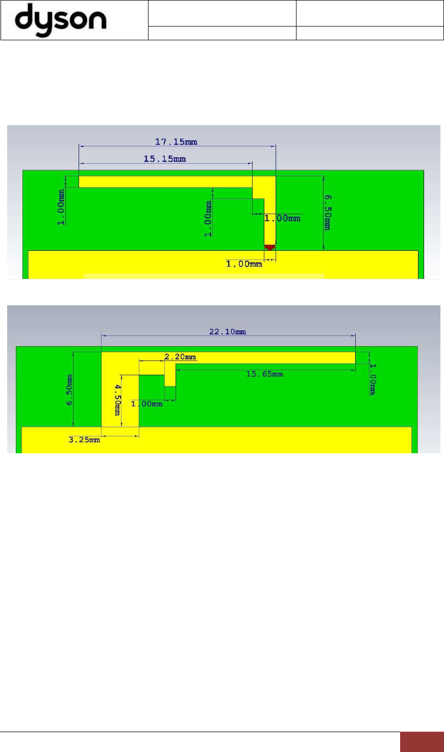
The antenna is a double sided PCB printed monopole. It is L-shape on top side and Inverted F IFA on
the other side as shown in the Figures 1, 2 below.
Antenna Specification
Type
PCB Printed Antenna
Frequency range
2.4 to 2.5GHz
Maximum Gain
2.08dBi
Impedance
50 ohm
VSWR
≤ 2:1
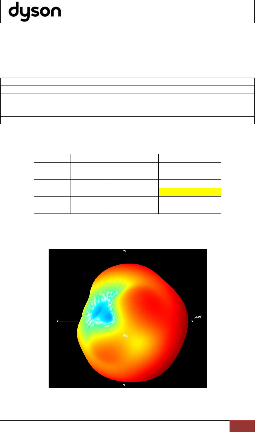
The maximum isotropic antenna gain the Radio module measured in UL OTA chamber is 2.08dBi @
2.46GHz
3D Antenna Pattern
Frequency Efficiency in %
Efficiency in dB Maximum Gain in dBi
2400000000
81% -0.92 1.82
2420000000
80% -0.96 1.69
2440000000
84% -0.77 1.84
2460000000
87% -0.58 2.08
2480000000
86% -0.63 1.91
2500000000
88% -0.57 1.94
Document Number 001
DOC
–
Wifi Module Installation
Guide
Revision
006
© Dyson Technology Limited 2015
5
The antenna is a double sided PCB printed monopole. It is L-shape on top side and Inverted F IFA on
the other side as shown in the Figures 1, 2 below.
The antenna is printed on PCB carrier board 35mm x 35mm x 1.6mm and 4.2 FR4. The wifi module is
mounted on the same board.
Figure1, PCB Printed antenna Top Side
Figure2, PCB Printed antenna Bottom Side
Document Number 001
DOC
–
Wifi Module Installation
Guide
Revision
006
© Dyson Technology Limited 2015
6
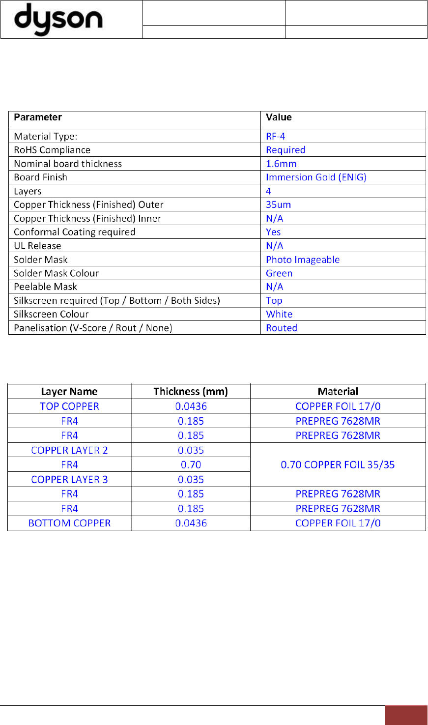
4. Bare Board Specification
4.1. Bare Board Processing
4.2. PCB Stack
Document Number 001
DOC
–
Wifi Module Installation
Guide
Revision
006
© Dyson Technology Limited 2015
7
4.3. PCB Guidelines:
1. Ground via holes must be located close to module ground pads.
2. Signal traces must not run underneath the module on the layer where the module is mounted.
3. Have a complete ground pour in layer 2 for thermal dissipation.
4. Have a solid ground plane and ground via holes under the module for stable system and thermal
dissipation.
5. Increase the ground pour in the first layer and have all of the traces from the first layer on the
inner layers, if possible.
6. Signal traces can be run on a third layer under the solid ground layer, which is below the module
mounting layer.
7. Power traces can be run on a third layer. Use ground to insulate signal traces from power. Use
thick traces for power.
8. Use lots of ground stitches around the RF transmission line (0.5mm pitch)
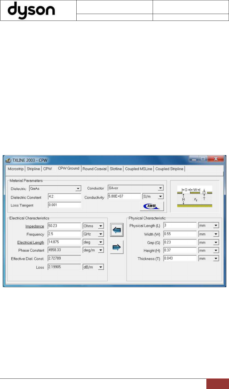
9. RF transmission line is 50Ω grounded CPW with dimensions calculated using ‘AWR txline 2003’.
Dimensions calculated using the PCB stack detailed in Section 4.2 using Er 4.2, dielectric height
from layer 1 to layer 2 of 0.37mm and trace plating thickness of 0.043mm. Width(W) = 0.55mm,
Gap(G) = 0.23mm, Height(H)=0.37mm.
10. Lots of stitches for ground in general
11. Lots of ground stitches around the board
12. No signal or power traces running on the edge of the board.