E F Johnson 2422607 700 MHz LAND MOBILE REPEATER User Manual
E. F. Johnson Company 700 MHz LAND MOBILE REPEATER Users Manual
UserManual.wiki
>
E F Johnson
>
2422607 User Manual
Users Manual
Navigation menu
Upload a User Manual
Namespaces
Wiki Guide
HTML
PDF
Info
Views
User Manual
Discussion / Help
Navigation
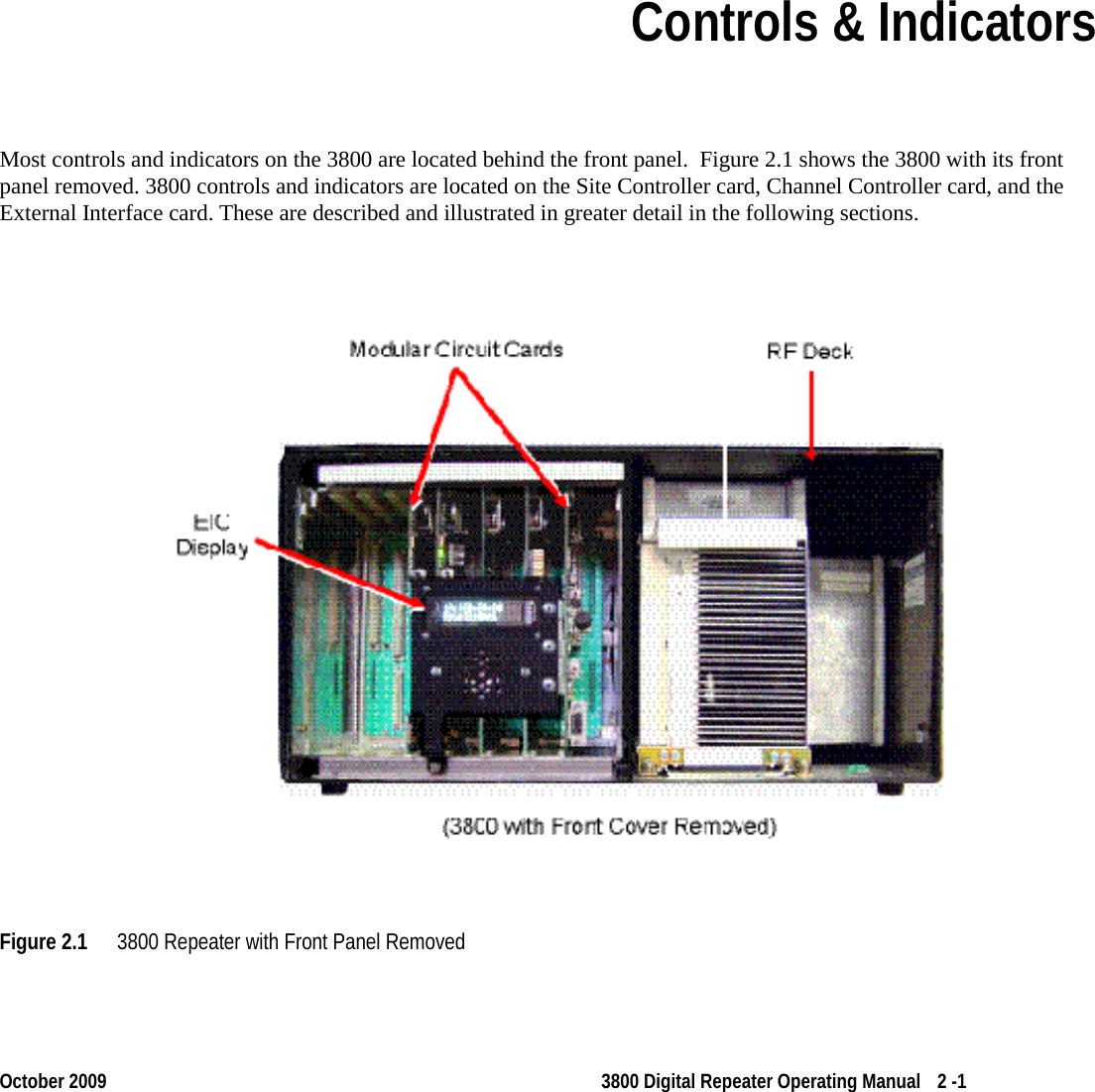
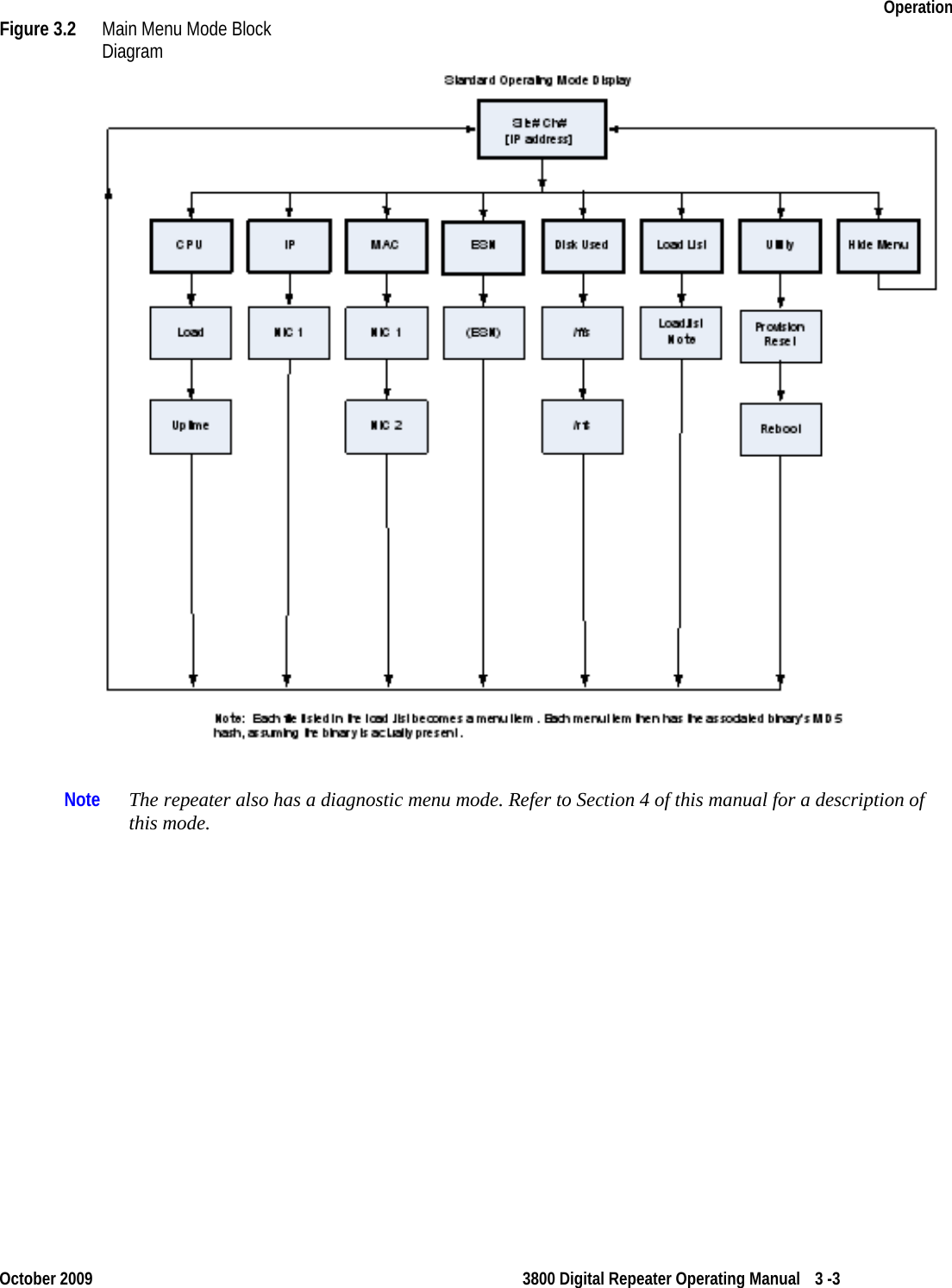
![3800 Information October 2009 3800 Digital Repeater Operating Manual 1 -7 1.4 Safety Information This repeater emits radio frequency (RF) energy when transmitting. Make sure to observe all RF energy exposure standards when installing, testing, repairing, and operating this radio equipment. The FCC has adopted a safety standard for human exposure to RF energy. Proper operation of this repeater under normal conditions results in user exposure to RF energy below the Occupational Safety and Health Act and Federal Communication Commission limits. - Do not allow the antenna to touch or come in very close proximity with the eyes, face, or any exposed body parts while the repeater is transmitting. - To comply with FCC RF exposure limits, do not operate the transmitter of a stationary radio (base station or marine radio) when a person is within fourteen (14) feet [four (4) meters] of the antenna. - Do not operate the repeater in explosive or flammable atmospheres. The transmitted repeater energy could trigger blasting caps or cause an explosion. - Do not operate the repeater without the proper antenna installed. - Do not allow children to operate transmitter equipped repeater equipment. Note The above warning list is not intended to include all hazards that may be encountered when using this repeater. This device complies with Part 15 of the FCC rules. Operation is subject to the condition that this device does not cause harmful interference. In addition, changes or modification to this equipment not expressly approved by EF Johnson Technologies could void the user’s authority to operate this equipment (FCC rules, 47CFR Part 15.19). The information in this document is subject to change without notice. EF Johnson Technologies will not be liable for any misunderstanding due to misinformation or errors found in this document. 1.5 More Information Additional information is available for the 3800 Digital Repeater. Contact your supervisor, site radio administrator or EF Johnson Technologies representative should you need one of these additional manuals. Refer to the following: - EF Johnson Technologies 3800 Digital Repeater Installation Manual](https://usermanual.wiki/E-F-Johnson/2422607/User-Guide-1249760-Page-7.png)
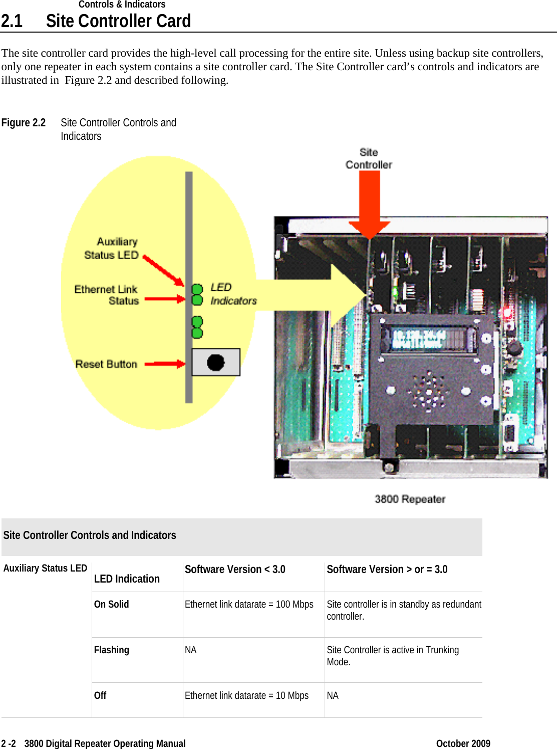
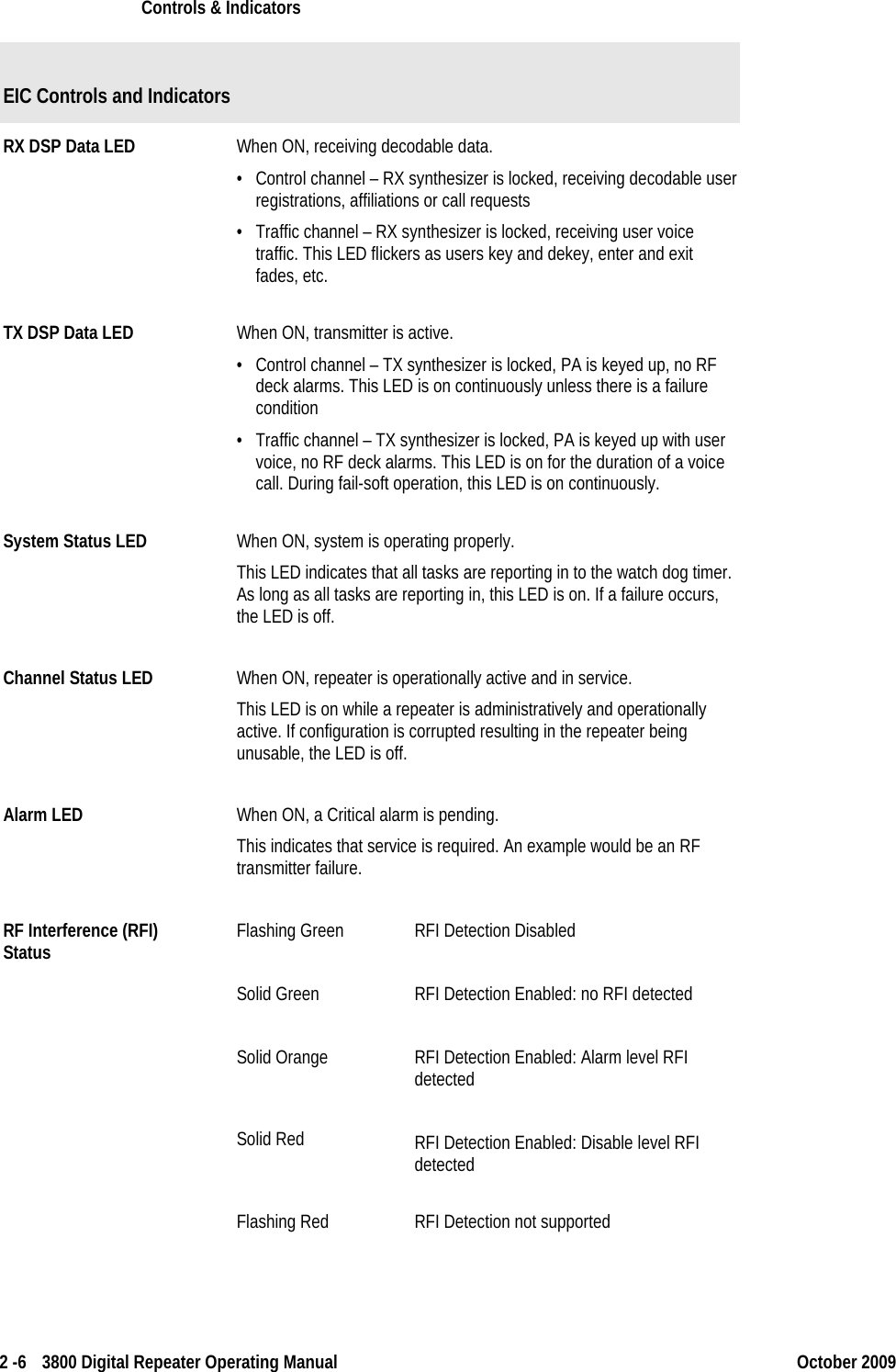
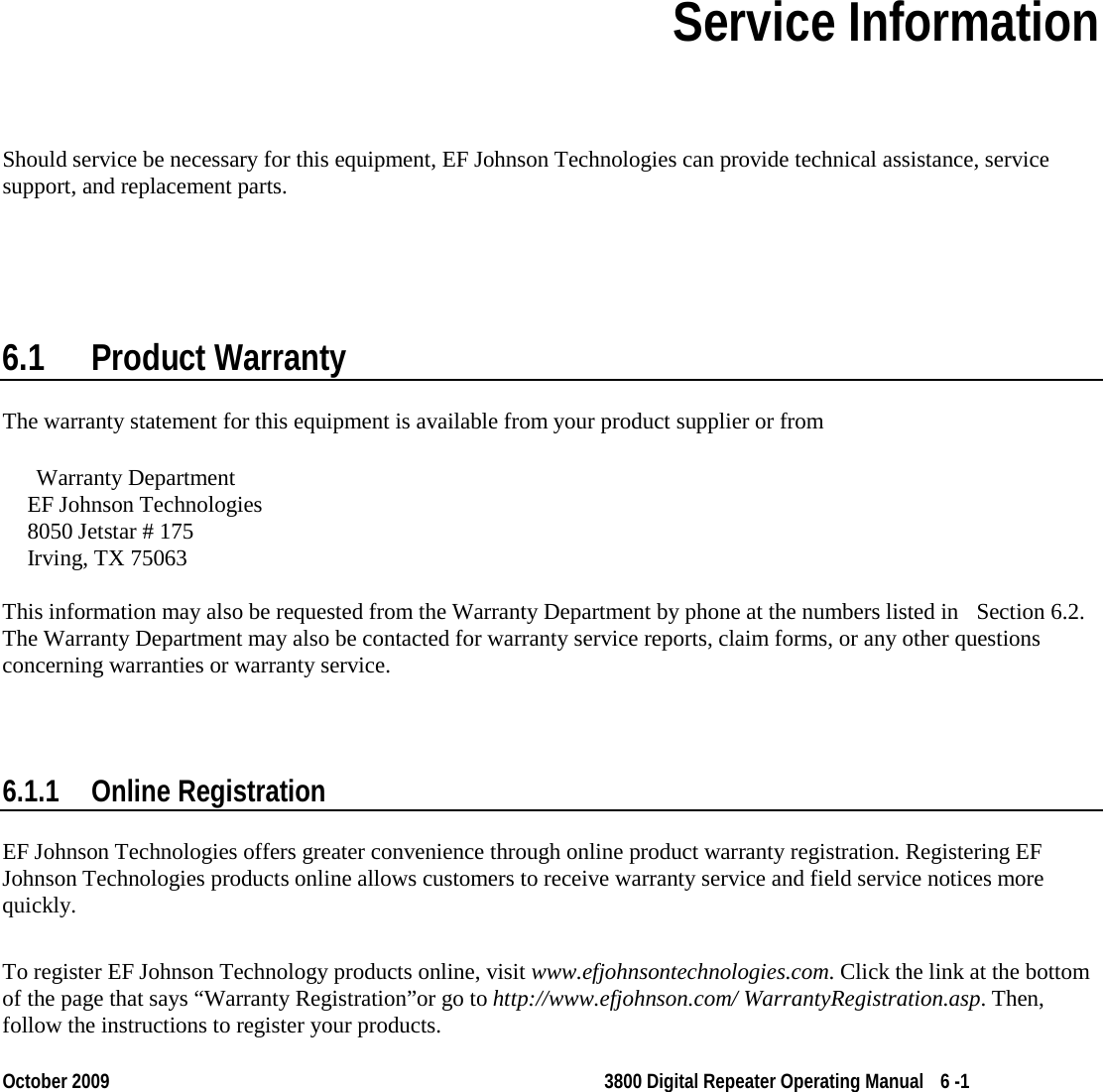
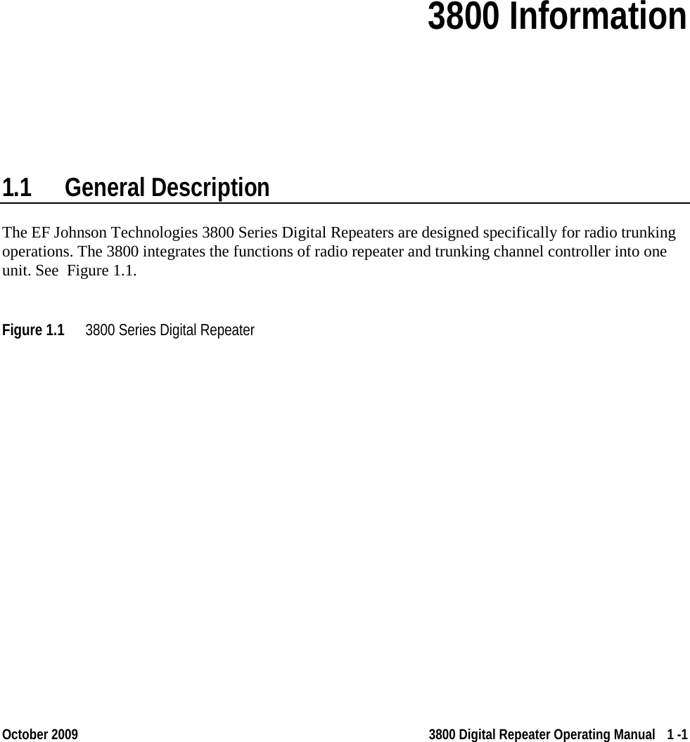
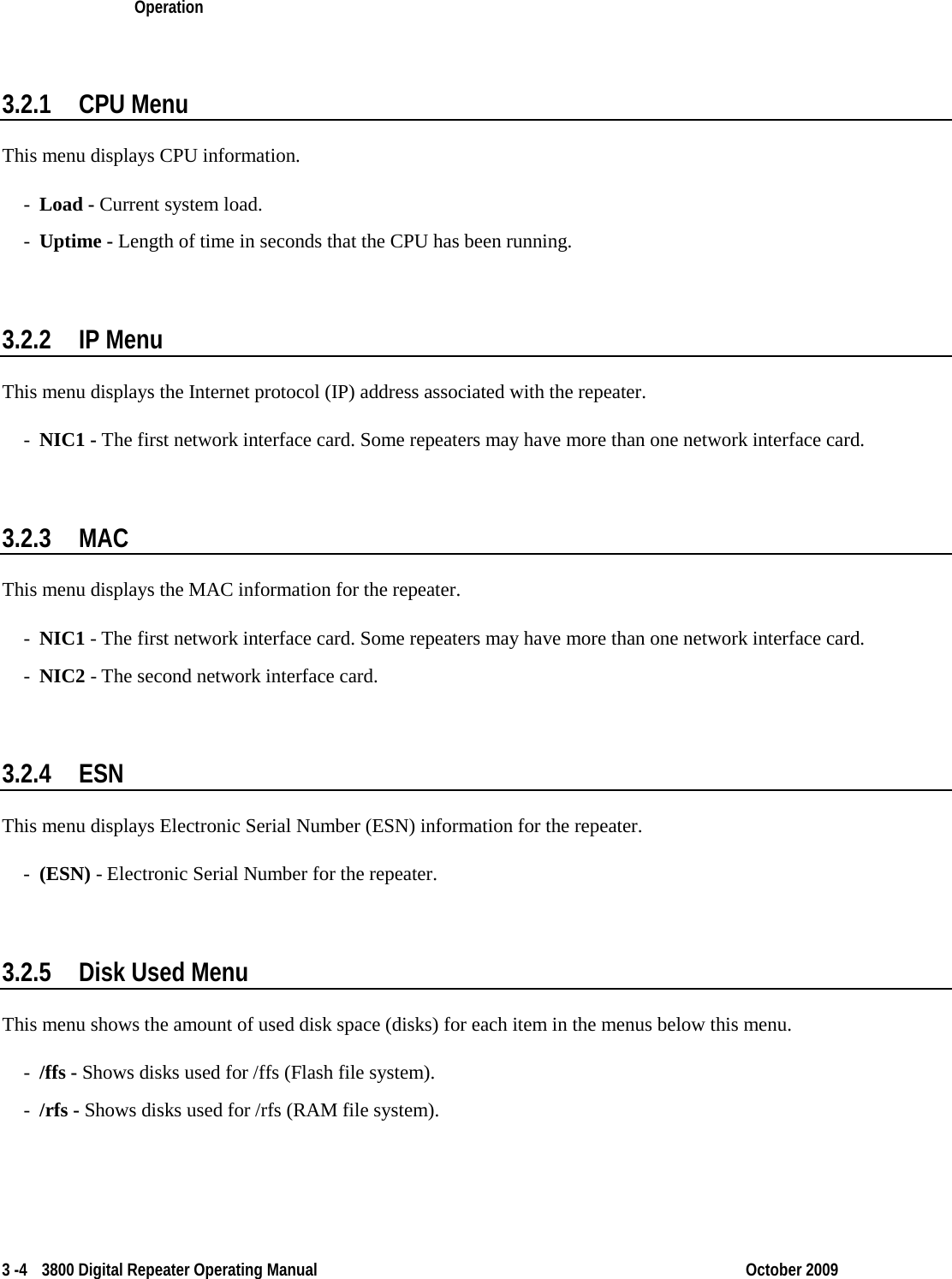
![Operation 3 -2 3800 Digital Repeater Operating Manual October 2009 3.2 EIC Menu Modes The main menu mode can be selected to display various repeater parameters. Figure 3.2 is a block diagram of the menu mode structThe menu mode is selected and controlled by the Menu Control knob as follows. ure. • To select the menu mode, press or rotate the Menu Control knob. The first main menu “CPU” is then displayed. • In general, rotating the Menu Control scrolls through available parameters, and pressing it selects the displayed parameter. • The icon in the upper right corner of the display indicates that if the knob is pressed, the next lower menu level is selected. Conversely, if is displayed, the next higher level is selected. The icon indicates that the displayed parameter or function is selected. • The icon in the left-most position of the bottom line indicates that additional parameters have scrolled off to the left. Likewise, the icon in the right-most position indicates additional parameters have scrolled off to the right. • Selecting [Back] returns a level up in menu hierarchy.](https://usermanual.wiki/E-F-Johnson/2422607/User-Guide-1249760-Page-17.png)
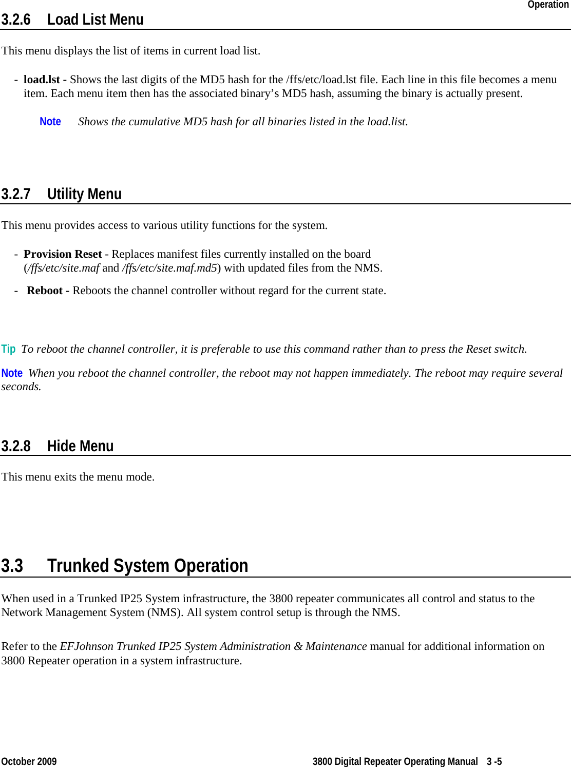
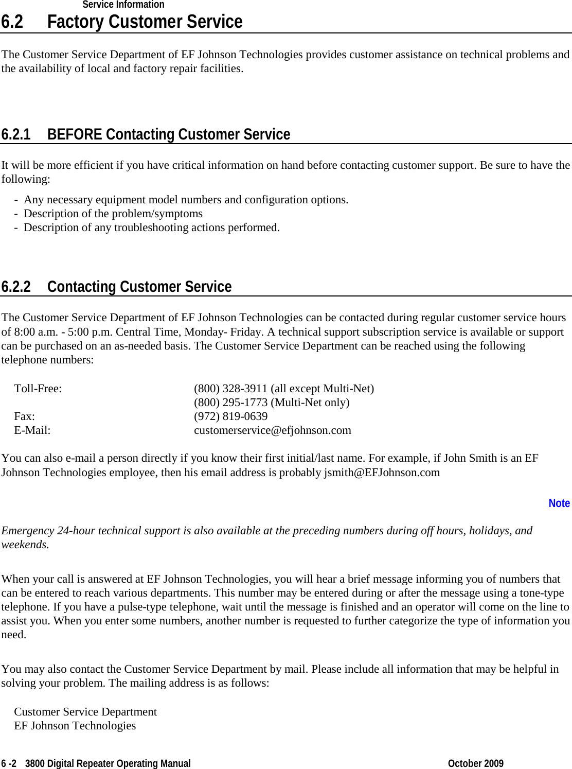
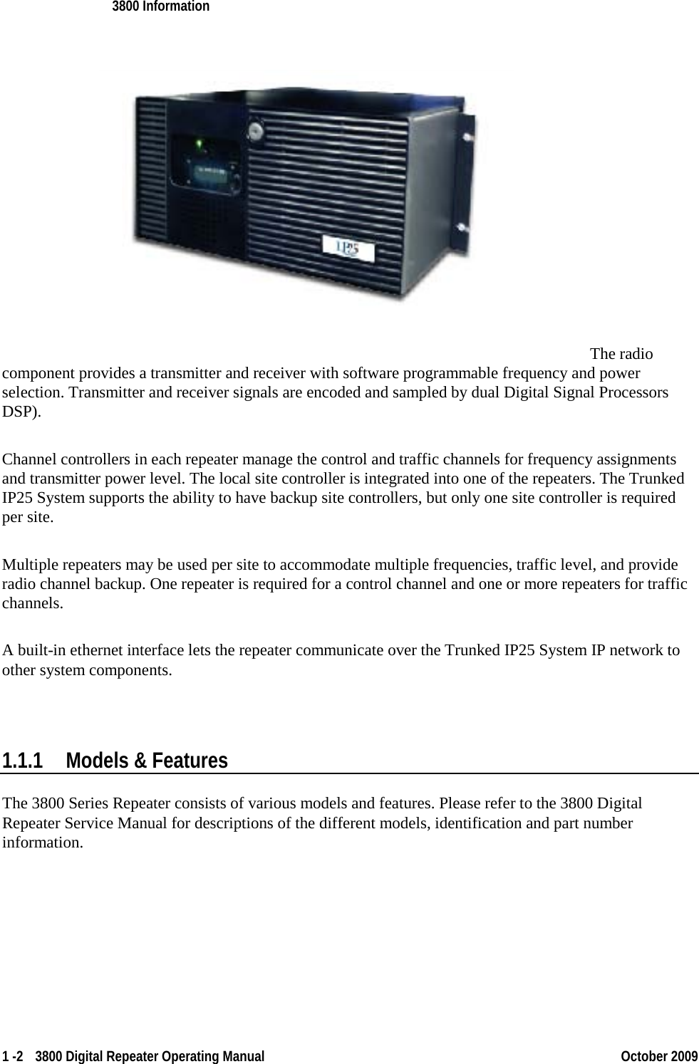
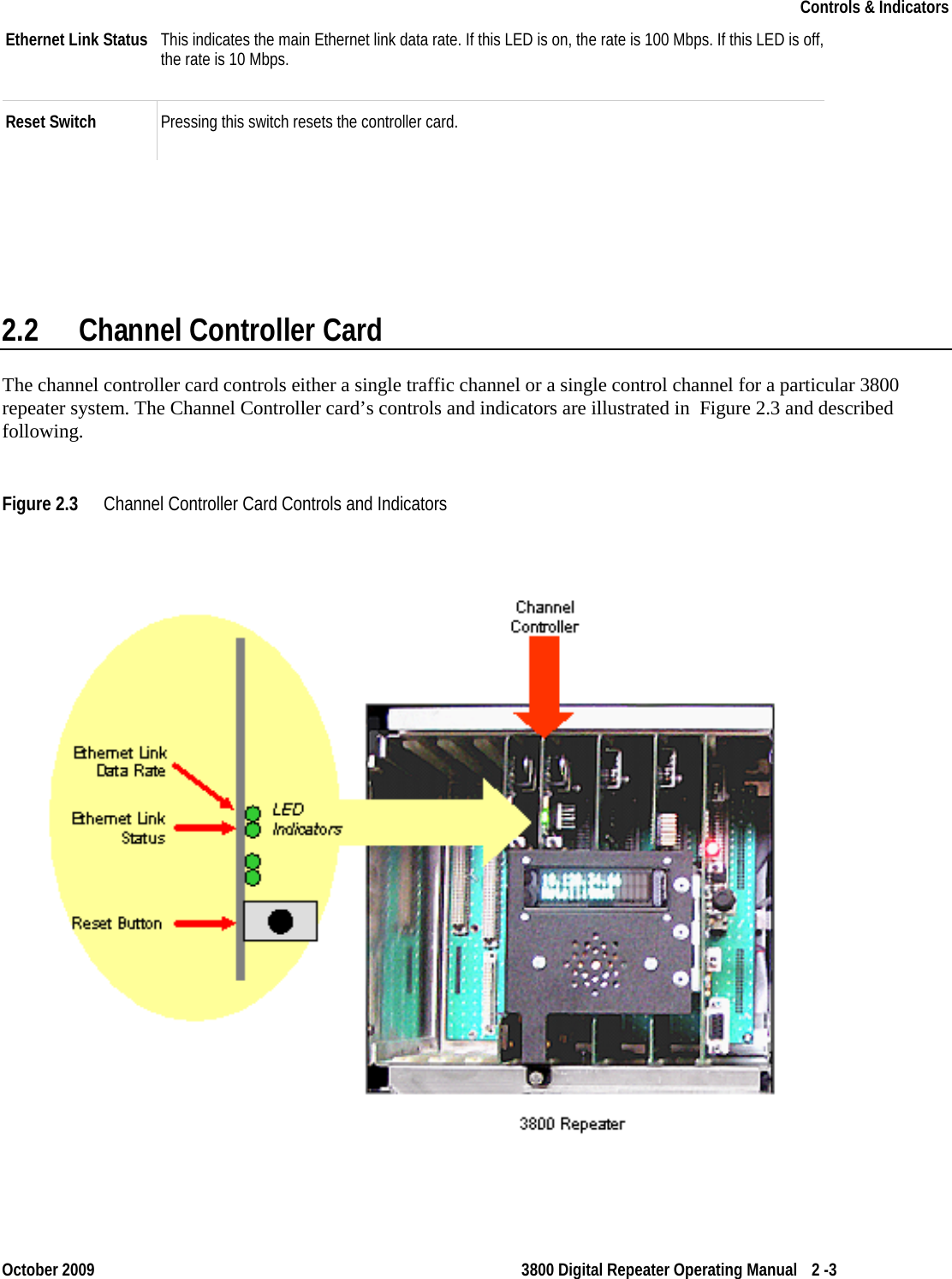
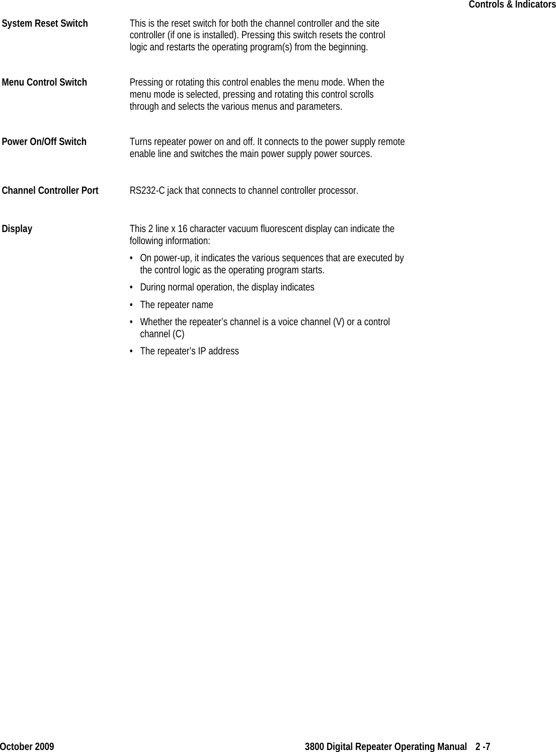
![.0.1 Monitors/Faults A monitor is a comparison of a sensor measurement to a predetermined limit or range. Monitoring of sensors is an ongoing process while running the diagnostics application. When a sensor measurement is out of range, a fault is generated. Detected faults result in the illumination of the red LED, and a corresponding message, which is viewable under the Faults menu. Monitor tests are selectable via the menu items TX Monitors, RX Monitors, or PSMonitors. When selected, a measured value used by the sensor comparison, and a Pass (“P”) or Fail (“F”) indication will be displayed. The P/F indicates the results of the comparison to the valid range limits. If a monitor is not enabled, an “NA” will be displayed. Monitors are enabled automatically according to the state of the transceiver. (i.e. some TX Monitors are enabled only when the transmitter is in the keyed state.) Even though monitors are always active when enabled, only one can be displayed at a time. Before starting the display of a monitor, a previously displayed monitor must first be stopped by selecting it a second time. The Fault LED is cleared on reboot. Diagnostic Mode Menu Tree The following lists the EIC menu tree available in diagnostic mode. Diagnostic Menu Tree (Continued) --> TX -Transmitter menu >> TX Tests -Test the transmitter. Use the Tx Config menu to configure the transmitter test. -- Cont [START/STOP] -Start or stop a continuous transmitter test -- Timed [START/STOP] -Start or stop a timed transmitter test -- Cycle [START/STOP] -Start or stop a cycled transmitter test -- -- [TOP] >> TX Control -Control the transmitter now. [BACK] -- Turn PA [ON/OFF]-Toggle transmitter state. The transmitter will be keyed at the currently configured frequency and power. No modulation will be applied. -- Turn Fan [ON/OFF]-Toggle fan state. Note that this control is an “or” control with the hardware circuitry. i.e. The fan cannot be turned off by this control if the current PA temperature exceeds the default fan-on set point. -- -- [TOP] [BACK]](https://usermanual.wiki/E-F-Johnson/2422607/User-Guide-1249760-Page-26.png)
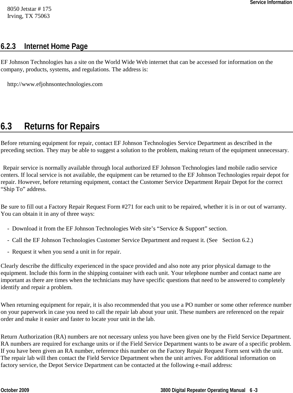
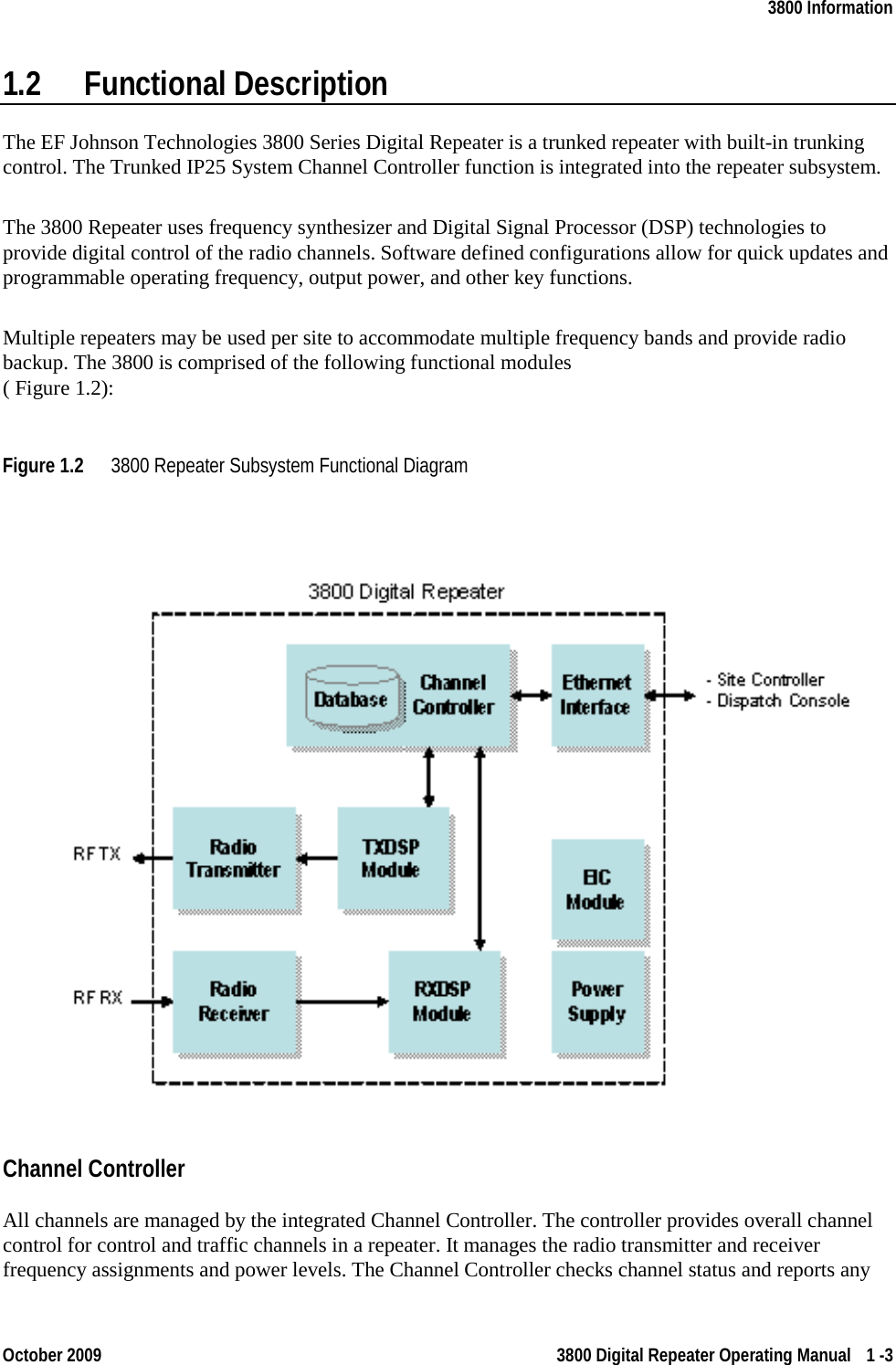
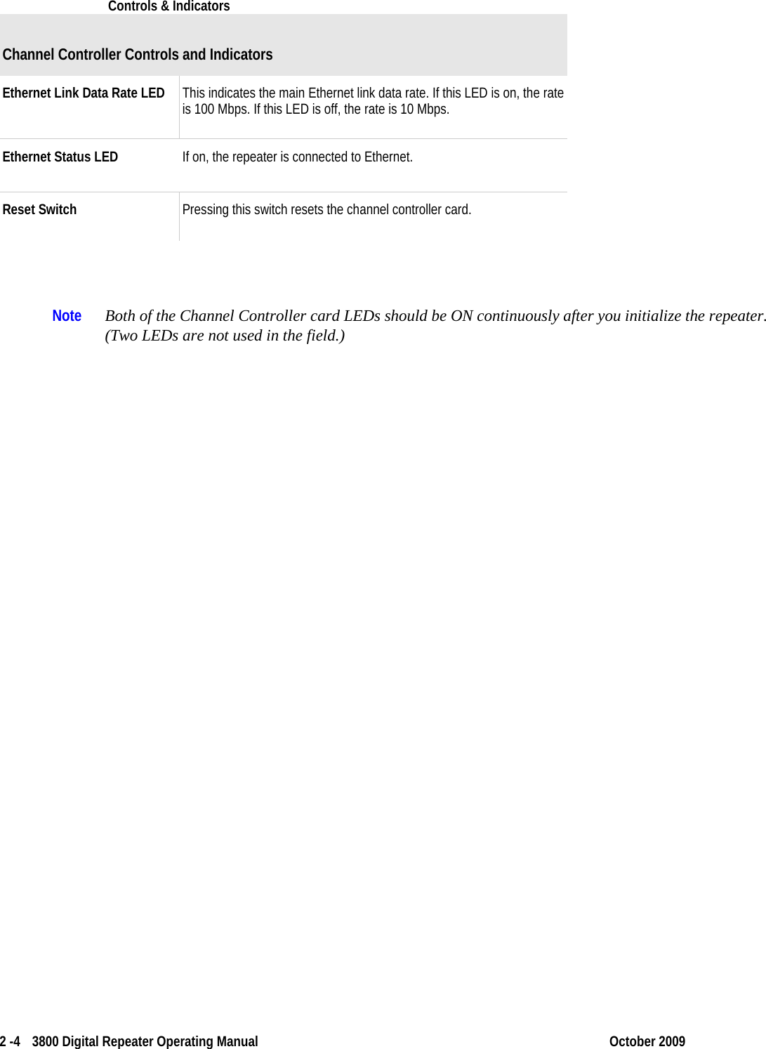
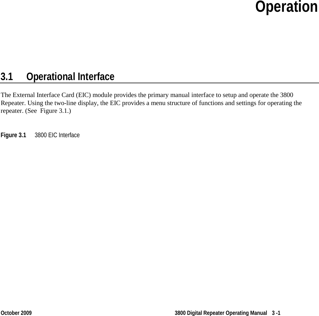
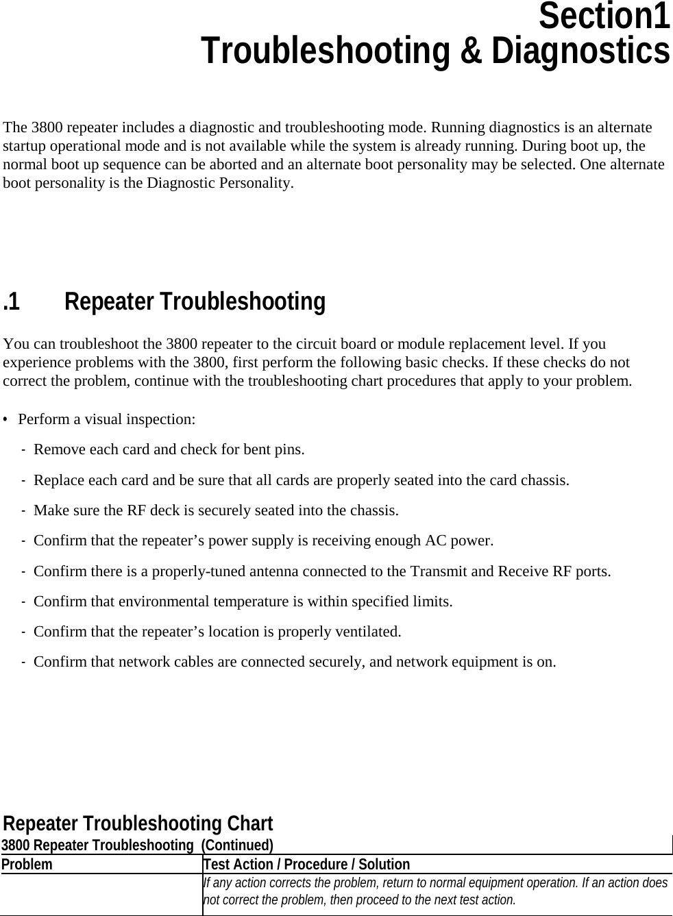
![>> TX Config -Configure the Tx Test. Note that configuration changes will not take effect until the next time the Tx Test is started. -- TX Waveform -Select the waveform used during the TX Test; refer to ANSI/TIA-102.CAAA-A-2002 “Digital C4FM/CQPSK Transceiver Measurement Methods” for details • [P25 1011Hz Tn] • Silence Tone • P25 Interfrnce • P25 Busy Patrn • P25 Idle Patrn • P25 Cal Patrn • P25 Inner Dev • P25 Outer Dev • P25 c4fmMod Fid • P25 Auto Freq • Analog Low Dev • Analog High Dev • Silent Carrier • Station ID • [TOP] • [BACK] -- TX Min Freq MHz -Display minimum tuned TX frequency. -- TX Max Freq MHz -Display maximum tuned TX frequency. -- TX Freq -Review/Edit TX Frequency. This frequency is applicable for Tx Tests and Tx Control. By default, the center of the tuned frequency range is used. -- TX Min PA Watt -Display minimum allowed power. -- TX Max PA Watt -Display maximum allowed power. -- TX Power -Review/edit TX Power in watts. This power setting is applicable for Tx Tests and Tx Control. By default, the maximum allowed power setting is used. -- Set Keyed [OFF/ON]-Sets transmit state during Tx Tests. -- Station ID -Review/edit Station ID. Only applicable when Tx Waveform = “Station ID” -- Dev Wfrm Param -Configure the modulation amplitude and frequency. • Low Dev Frq Hz -Configure the modulation frequency for the “Analog Low Dev” waveform. • Hi Dev Frq Hz -Configure the modulation frequency for the “Analog High Dev” waveform. • Low Dev Amp Hz -Configure the amplitude for the “Analog Low Dev” waveform.](https://usermanual.wiki/E-F-Johnson/2422607/User-Guide-1249760-Page-27.png)
![• Hi Dev Amp Hz -Configure the amplitude for the “Analog High Dev” waveform. • [TOP] • [BACK] -- Test Duration -Set the Tx Test duration. • Timed (sec) -Set the Tx Test duration in seconds. Only applicable when Tx Test is started as “Timed” • Cycled - Set the Tx Test duration in number of Tx cycles, where a Tx cycle includes a duration of time where the transmitter is keyed, followed by a duration of time where the transmitter is dekeyed. •• Test Key Time - Number of seconds to keep PA keyed •• Test Dekey Time - Number of seconds to keep PA dekeyed •• Test Cycles - number of iterations •• •• [TOP] • [TOP] [BACK] • [BACK] -- >> TX Monitors - Shows the result of a transmitter monitor. See Monitors/Faults for more detail. For many of the monitors, the transmitter must be in the keyed state as a result of actions under the Tx Control, or the Tx Tests menu items. [BACK] -- TX Synth Lock - Transmit synthesizer. The measurement is FALSE when locked, TRUE when not locked. -- TX Temperature - Temperature of the PA in degrees C. This monitor checks that the PA does not get too hot. -- TX Fwd Power - Output of forward power sensor in volts when keyed. This monitor checks for a minimum level of forward power when the transmitter is keyed. -- TX NoFwd Power - Output of forward power sensor in volts when dekeyed. This monitor checks that power is not radiated when not keyed. -- TX Power1 - Output of Exciter current sensor. Not applicable in all models. -- TX Power2 - Output of Exciter current sensor. Not applicable in all models. -- TX Power3 - Output of Exciter current sensor. Not applicable in all models. -- TX Power4 - Output of Exciter current sensor. Not applicable in all models. -- TX Imbal ½ - Ratio of Tx Power1 to Tx Power2 or Tx Power2 to Tx Power1. Number will always be greater than 1. Not applicable in all models. -- TX Imbal ¾ - Ratio of Tx Power3 to Tx Power4 or Tx Power4 to Tx Power3. Number will always be greater than 1. Not applicable in all models.](https://usermanual.wiki/E-F-Johnson/2422607/User-Guide-1249760-Page-28.png)
![-- TX VSWR - Voltage Standing Wave Ratio. This is the ratio of the forward power sensor to the reflected power sensor given that both measurements exceed the minimum measurement. The minimum measurement is defaulted to 0.9 volts. If either of the sensors is below the minimum measurement, the resulting sensor measurement will be 2.001. -- TX Fan Op - Fan Operating sensor in volts. -- TX Fan1 Cur - Fan Current sensor 1 in volts. -- TX Fan2 Cur - Fan current sensor 2 in volts. -- -- [TOP] >> [BACK] [BACK] --> RX -Receiver menu >> RX Tests - Test the receiver. Use the Rx Config menu to configure the receiver test. -- BER [START/STOP] Bit Error Rate Test. Results displayed in%. -- RSSI [START/STOP] Receive Signal Strength (relative). Results displayed in%. Not all RF decks support this feature. -- -- [TOP] >> RX Config - Configure the RX Tests. [BACK] -- RX Min Freq MHz - Display minimum tuned RX frequency. -- RX Max Freq MHz - Display maximum tuned RX frequency. -- RX Freq - Review/Edit RX Frequency. This frequency is applicable for Rx Tests. By default, the center of the tuned frequency range is used. -- -- [TOP] >> RX Monitors - Shows the result of a receiver monitor. See Monitors/Faults for more detail. [BACK] -- RX Synth Lock - Receiver synthesizer. The measurement is FALSE when locked, TRUE when not locked. -- -- [TOP] >> [BACK] [BACK] --> Power Supply >> PS Tests - Test the power supply. -- PS Oput [START/STOP] -Displays the primary output of the power supply in volts. -- -- [TOP] [BACK]](https://usermanual.wiki/E-F-Johnson/2422607/User-Guide-1249760-Page-29.png)
![>> PS Monitor - Shows the result of a power supply monitor. See Monitors/Faults for more detail. -- PS Temp [START/STOP]- Power supply temperature in degrees C. -- PS Batt Warn-- - The measurement is TRUE when backup battery level is sufficient for operation, FALSE when belw the warning level. It is also TRUE if the backup battery option is not installed. PS Batt Fail-- - The measurement is TRUE when backup battery level is at or above the failed threshold, FALSE when below the failed level. It is also TRUE if the backup battery option is not installed. PS AC Fail -- - The measurement is TRUE when AC is present, FALSE when AC is not (assuming presence of backup battery). -- [TOP] -- [BACK] --> Alarms - This feature is currently not supported [BACK] >> Alarm Tests -- -- Alarm Input - Test the status of the alarm inputs on the rear of the chassis. This test is currently not supported. -- [TOP] >> Alarm Control [BACK] -- Alarm Toggle [Set/Reset] Control the alarm outputs on the rear of the chassis. This control is currently not supported. -- -- [TOP] >> [BACK] [BACK] --> Sensor/Other >> Sensor Tests - Display the raw measurement of the corresponding sensor, in volts. -- TX Mod - TX Modulation -- HS TX Syn Lock - High Stability TX Synthesizer Lock -- TX Syn Lock - TX Synthesizer Lock -- AGC - Receiver Automatic Gain Control -- Gnd - Ground (through resistor) -- PS Temp - Power Supply temperature sensor. -- RX WB - RX Wideband. -- RX RSSI/Q- - Multiplexed RSSI or QRX -- Inj Lvl - Receiver Injection Level](https://usermanual.wiki/E-F-Johnson/2422607/User-Guide-1249760-Page-30.png)
![-- HS RX Syn Lock - High Stability RX Synthesizer Lock -- RX Syn Lock - Rx Synthesizer Lock -- 5 Volt - Connected to 5 volt supply through R divider. -- Fan2 Cur - Fan current sensor 2. -- Fan1 Cur - Fan current sensor 1. -- 26.5 Volt - Connected to 26.5 volt supply through R divider. -- Fan1 Op - Fan Operational sensor. -- Fwd Power - TX Forward Power sensor -- Power 1 - Power 1 sensor. -- Power 2 - Power 2 sensor. -- Power 3 - Power 3 sensor. -- Power 4 - Power 4 sensor. -- Refl Power - TX Reflected Power sensor. -- PA Temp - PA Temperature Sensor -- 2.5 Volt - 2.5 volt through R divider. -- -- [TOP] >> ESN - Electronic Serial Number [BACK] >> >> MAC Addr - Hardware ethernet address IP NIC 1 >> Diag Version - Version number of the diagnostic applications >> Diag Menu Ver - Version number of the diagnostic menu >> [BACK] --> Faults - Maintain a list of issued detected while running diagnostics -- -- (Updated as they occur) --> Exit Diag Menu – Allows for selection of another boot personality (if one exists) [BACK] --> Reboot - Reboots](https://usermanual.wiki/E-F-Johnson/2422607/User-Guide-1249760-Page-31.png)
![Menu Tips These menu items will also be prefixed by the double up, menu item prefix. See above in this symbol table. postfix down arrow Selecting this menu item will navigate into a sub-menu prefix up arrow Current position is within a submenu, navigating “BACK” will go transition one menu level up. prefix, double up arrow Indicates the associated action will change the position to the highest level menu. This is a shortcut, which can save many navigation steps. left arrow Selecting the menu item performs an action; activates the association functionality. If an item supports editing, Edit/ Navigation mode will be enabled. solid block Edit/Navigation mode underscore Edit/Modify mode [BACK] Navigates on menu level up. Every menu except the top level menus will contain one of these. [TOP] Navigates to the top-most menu level. Only submenus two levels or greater will contain this navigation aid.](https://usermanual.wiki/E-F-Johnson/2422607/User-Guide-1249760-Page-32.png)