E F Johnson 2424310 Non-Broadcast Transceiver User Manual 4300ServMan VHF
E. F. Johnson Company Non-Broadcast Transceiver 4300ServMan VHF
UserManual.wiki
>
E F Johnson
>
2424310 User Manual
>
manual part 1
Contents
1.
manual part 1
2.
manual part 2
3.
manual part 3
4.
manual part 4
manual part 1
Navigation menu
Upload a User Manual
Namespaces
Wiki Guide
HTML
PDF
Info
Views
User Manual
Discussion / Help
Navigation


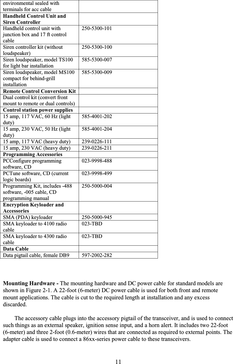
![7 1.2.4 AVAILABLE MOUNTING OPTIONS Front Mount - The operating controls are on the front on the radio, so the radio must be mounted within reach of the user. Remote Mount, Single Control Unit - The operating controls are located on a remote mounted control unit. The radio does not have operating controls. Remote Mount, Dual Controls - A remote control unit is connected to the front mount radio. This allows control from the front panel and the remote control unit. Remote Mount, Dual Remote Control Units - Two remote control units are connected to the remote mount radio. This allows control from both remote control units. 1.2.5 SYSTEMS, CHANNELS, AND ZONES A zone and channel are selected to place and receive calls. The following describes the relationship between systems, channels, and zones. Systems A system is a collection of channels or talk groups belonging to the same repeater site. It defines all the parameters and protocol information required to access a site. Up to 16 systems of any type can be programmed. The maximum number of channels assignable to a system is limited to approximately 256 (or the available memory space as described in the following information). Channels A channel selects a radio channel or talk group in a system as follows: Conventional Analog Mode - A channel selects a specific radio channel, Call Guard [Continuous Tone Coded Squelch System (CTCSS)/Digital Coded Squelch (DCS)] squelch coding, and other parameters unique to that channel. Conventional Project 25 Mode - A channel selects a specific radio channel, NAC squelch coding, talk group ID, and other parameters unique to that channel. Trunked Project 25 Mode - A channel selects a specific talk group ID and other parameters unique to that talk group. SMARTNET/SmartZone and Project 25 Trunked Operation - A channel selects a specific talk group, announcement group, emergency group, and other parameters unique to that talk group. As previously described, a maximum of up to 256 channels can be programmed. Although it is theoretically possible to program any combination of systems that produces up to 256 total channels, the maximum number may be limited by the available memory. For example, since more memory is required to program a SMARTNET system than a conventional system, the total number of channels decreases as the number of SMARTNET systems increases. The](https://usermanual.wiki/E-F-Johnson/2424310.manual-part-1/User-Guide-520073-Page-7.png)
![8 programming software displays a bar graph which shows the amount of available memory space that is used by the current data. Refer to Section 4 for more information. Zones A zone is a collection of up to 16 channels of any type. For example, a zone could include 12 conventional channels and 4 SMARTNET channels. One use of zones may be to program the channels used for operation in a specific geographical area. Up to 16 zones can be programmed. 1.2.6 PROGRAMMING Transceiver programming is performed using a PC-compatible computer and an EFJohnson Remote Programming Interface (RPI) and PC Configure programming software (see Table 1-1). Programming is described in a separate included manual. Refer to Section 4 for more information. 1.2.7 ALIGNMENT Transceiver alignment is performed using the same computer and RPI used for programming (see preceding section) and special PCTune™ software. All adjustments are made electronically using the software (no manual adjustments are required). Alignment is described in Section 6. 1.3 PRODUCT WARRANTY The warranty statement for this transceiver is available from your product supplier or from the Warranty Department, E.F. Johnson Company, 1440 Corporate Drive, Irving, TX 75038-2401. This information may also be requested from the Warranty Department by phone as described in Section 1.7. The Warranty Department may also be contacted for Warranty Service Reports, claim forms, or any other questions concerning warranties or warranty service. 1.4 MODEL NUMBER BREAKDOWN The radio model number is located on the radio identification label attached to the bottom cover (see Figure 1-1). The following is a breakdown of this number: [Insert label graphic here] Figure 1-1 Identification Label Example 242-5MFT-SEC-OADE](https://usermanual.wiki/E-F-Johnson/2424310.manual-part-1/User-Guide-520073-Page-8.png)
![10 E (Encryption and Security Software Options) B - Default [no Over-The-Air-Rekeying (OTAR)] C - OTAR Project 25 Conventional D - OTAR Project 25 Trunked/Conventional * 1.5 SERIAL NUMBER BREAKDOWN The radio serial number is located on the radio identification label attached to the bottom cover (see Figure 1-1). The following is a breakdown of this number: 1.6 ACCESSORIES The accessories available for this transceiver are listed in Table 1-1. A brief description of some of these accessories follows: Table 1-1 4300 Accessories Accessory Part No. Mounting Accessories Mounting bracket & hardware kit (standard) DC power cable & hardware, 22 ft. (standard) Accessory wire kit Lockable Mounting Tray Microphones Standard amplified dynamic 250-0740-310 DTMF without mem, commercial 589-0016-028 DTMF without mem, env seal WR805 587-9650-015 Noise canceling, weather resistant 589-0016-592 Desk microphone 589-0012-021 Speakers External, 5-inch, 15-Watt 3.2 Ω environmental sealed with plug for HHC 250-0151-005 External, 5-inch, 15-Watt 3.2 Ω 250-0151-006](https://usermanual.wiki/E-F-Johnson/2424310.manual-part-1/User-Guide-520073-Page-10.png)

![19 Mounting Location Dash Mount (Remote mount optional) Zones/Channels Up to 16 zones with 16 channels per zone Transmit/Receive Separation Any frequency within the range Channel Spacing 12.5, 15, 25, and 30 kHz Maximum Deviation 25 kHz analog - 5 kHz 12.5 kHz analog - 2.5 kHz Frequency Stability Receive and Transmit 2.5 PPM [–22° to +140° F (–30° to +60° C)] Dimensions (without antenna) 2.1 inches high x 7.2 inches wide x 8.3 inches deep (5.3 cm x 18.2 cm x 21.1 cm) Weight (with standard battery) 5 lbs. 4 oz. (2.38 kg) Supply Voltage 13.6 volts DC nominal, negative ground Current Drain (maximum) Standby - 600 mA Receive (rated audio out) - 2.7 A Rated Transmit Power - 13.2 A RECEIVER Sensitivity 0.35 µV (analog mode 12 dB SINAD), 0.35 µV (digital mode 5% BER) Selectivity –75 dB Spurious and Image Rejection –75 dB Intermodulation –75 dB Hum and Noise 40 dB at 25 kHz, 34 dB at 12.5 kHz Maximum Frequency Spread Any spread within the range Audio Power Output 5 W with internal speaker (12 W with external 4-Ω speaker) Audio Distortion Less than 3% at 1 kHz TRANSMITTER RF Power Output 10 - 50 W variable standard Spurious and Harmonic Emissions –70 dB FM Hum and Noise –45 dB at 25 kHz bandwidth Audio Modulation 8K10F1E, 11K0F3E, 16K0F3E, 20K0F1E Audio Distortion Less than 3% at 1 kHz Maximum Frequency Spread Any spread within the band](https://usermanual.wiki/E-F-Johnson/2424310.manual-part-1/User-Guide-520073-Page-19.png)
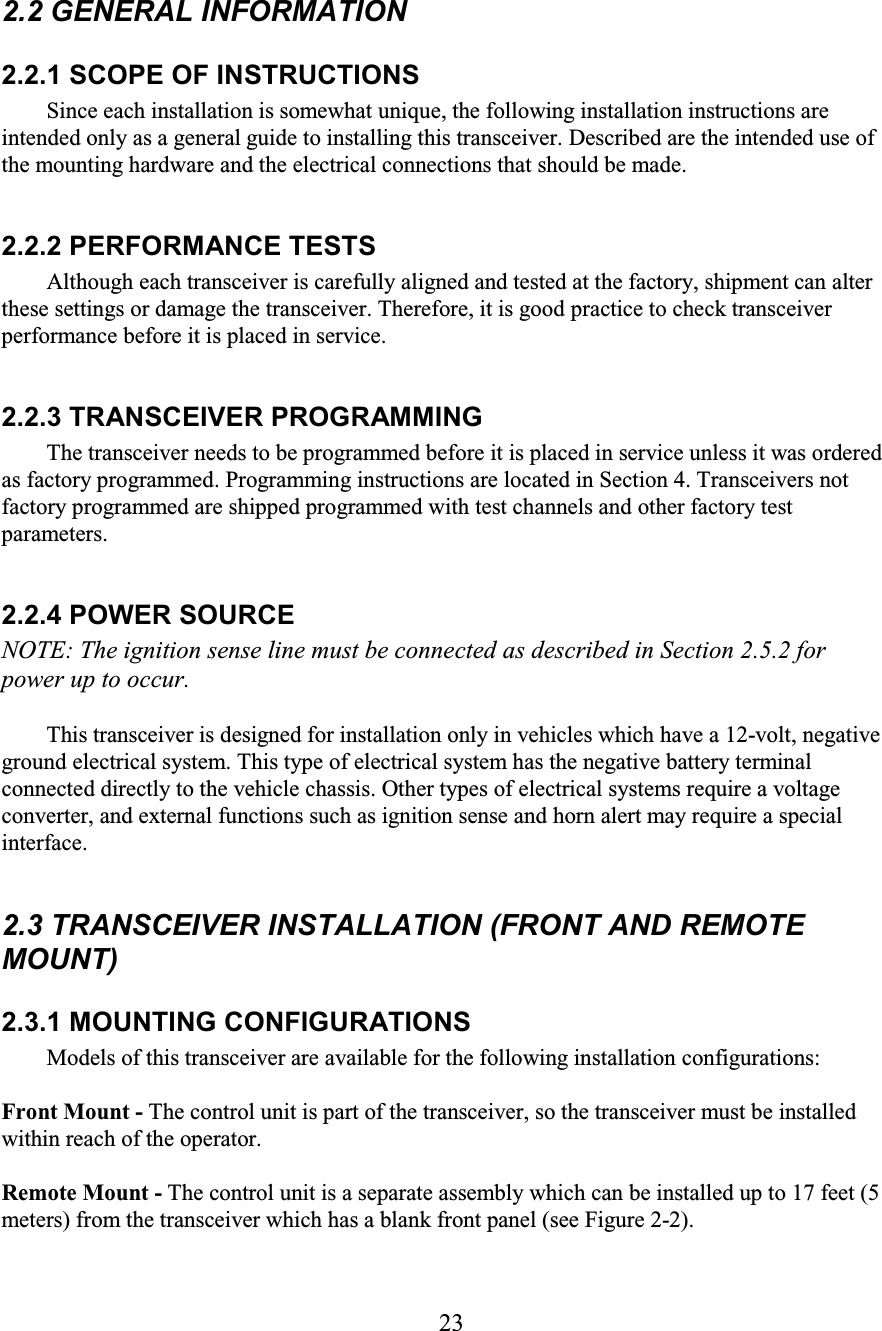
![25 2.3.2 SELECTING A MOUNTING LOCATION Front-mount transceivers are designed for mounting in a location near the operator such as the dash, console, or transmission hump. Remote-mount transceivers are designed for mounting in an out-of-the-way location such as the trunk. WARNING The mounting location of the transceiver or control unit can affect safe operation of the vehicle. Follow these precautions when installing this transceiver: • Mount it where it does not interfere with operation of the vehicle controls and where the operator can easily see the display and reach the controls. • Mount it where it is least likely to cause additional injury in case of an accident. • Air bags deploy with great force. Therefore, do not mount a transceiver or control unit anywhere near the deployment area or place any other objects in the deployment area. 2.3.3 MOUNTING KITS The following kits may be used to install this transceiver. Components in these kits are shown in Figures 2-1, 2-2, and 2-5. Cable and Hardware Kit, Part No. 023-9750-010 Includes a 22-foot (6.7-meter) power cable, microphone hanger and ground wire, splice connectors, and all the hardware (such as screws) that is normally required for installation. Transceiver Mounting Kit, Part No. 023-9750-012 Includes a transceiver mounting bracket, four knobs, and mounting screws. Accessory Wire Kit, Part No. 023-9750-011 Includes a wire assembly that is used to connect the ignition sense input and accessories. 2.3.4 MOUNTING STANDARD POWER TRANSCEIVER Proceed as follows to mount a standard power front or remote mount transceiver: 1. Check the area underneath the selected mounting area for wiring, brake and gas lines, or other components that could be damaged when the mounting bracket is installed. Then install the mounting bracket using the included self-drilling screws or other screws if desired. 2. Install the transceiver in the bracket using the included knobs. 3. With front-mount transceivers, install the microphone hanger in a convenient location using the screws for sheet metal or plastic. The hanger must be connected to chassis ground for proper operation of functions such as monitoring and scan. If required, ground the hanger using the included ground wire. Figure 2-3 [not used]](https://usermanual.wiki/E-F-Johnson/2424310.manual-part-1/User-Guide-520073-Page-25.png)
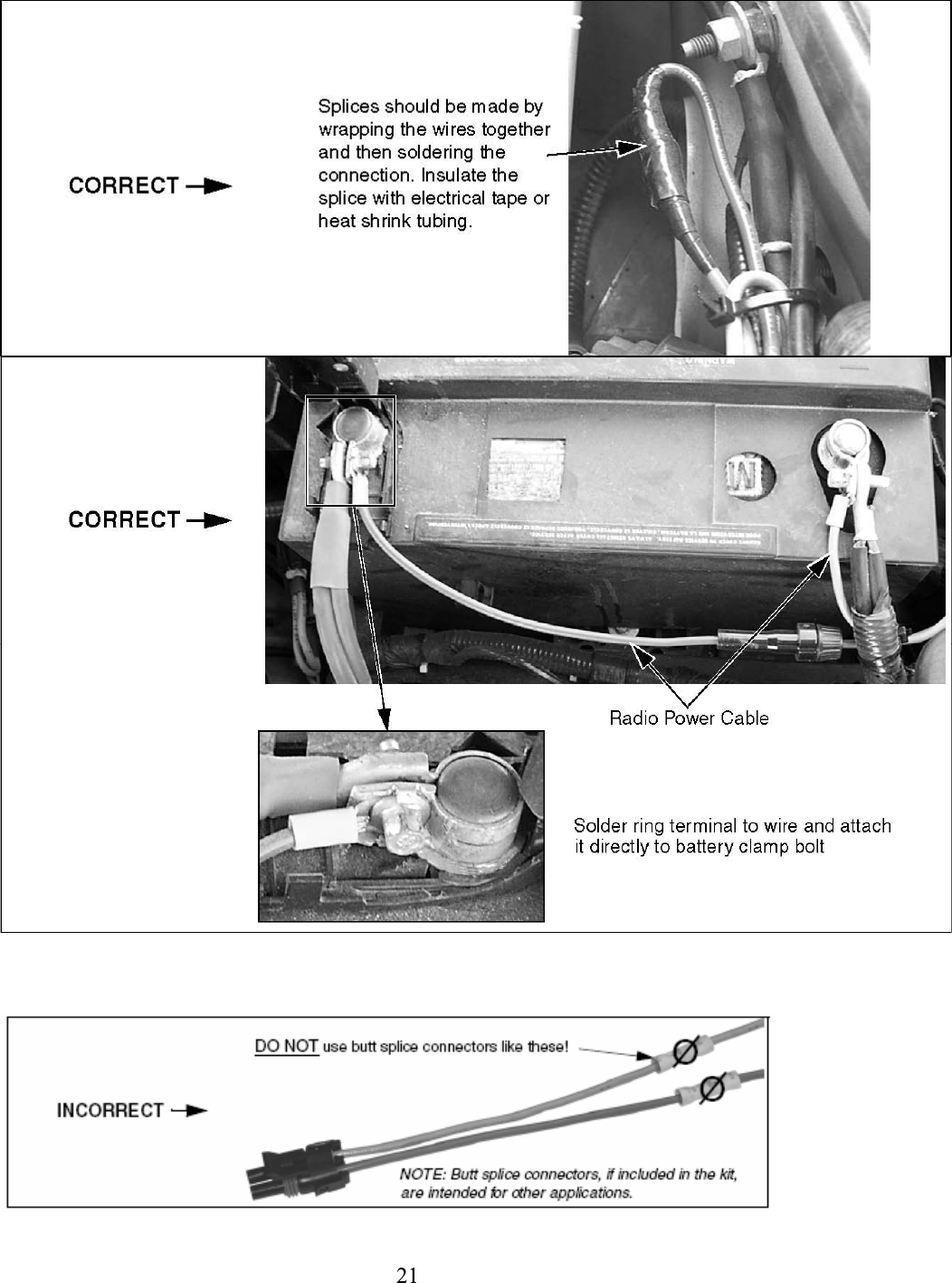
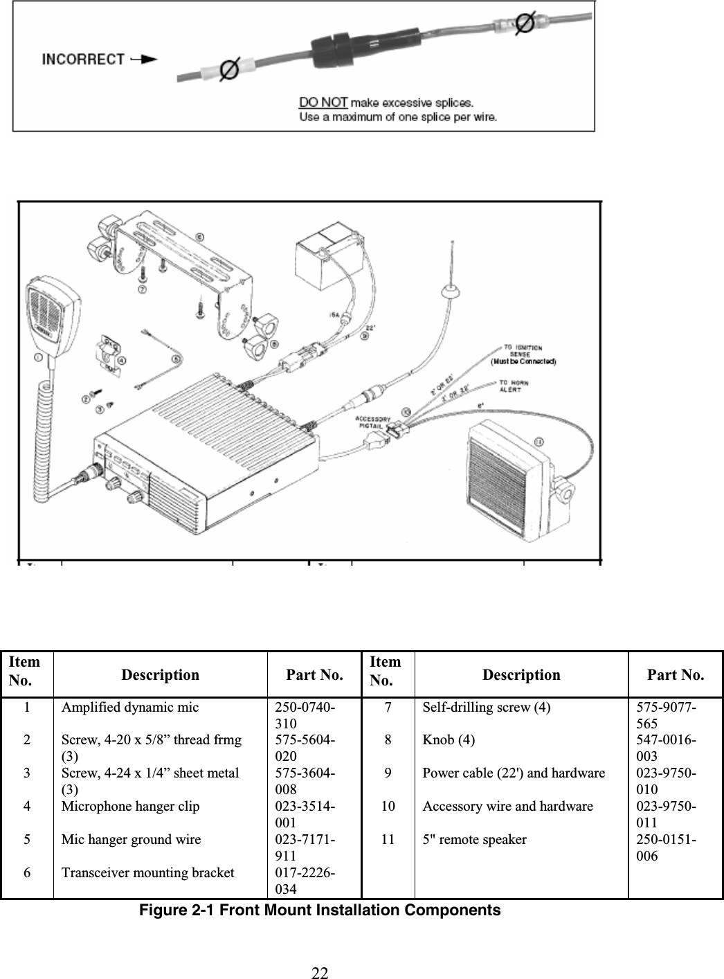
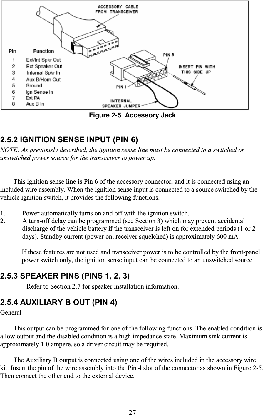
![26 2.4 POWER CABLE INSTALLATION NOTE: As described in Section 2.1,connect the power cable directly to the vehicle battery, and to an unswitched power source so that it de-affiliates when power is turned off. 2.4.1 STANDARD MODELS Refer to Figures 2-1 or 2-2 and proceed as follows: 1. Disconnect the negative cable from the battery to prevent damage from accidental short circuits. 2. Route the red and blue power cables to the battery. To minimize the chance of a short circuit occurring in the unfused portion of the cable, make sure the fuseholder is connected as close as possible to the positive battery terminal. 3. As described in Section 2.1, if there is excess cable, cut it to length. It may also be necessary to cut the cable if it must be routed through an opening that is not large enough to clear the fuseholder. Splice the wires by tightly wrapping them together and then soldering the connection (do not use a butt splice connector). Insulate the connection using electrical tape or heat shrink tubing. 4. Connect the red power cable to the positive (+) terminal of the battery. 5. Connect the blue cable to the negative (–) battery terminal. 6. Plug the power cable into the transceiver and reconnect the negative battery cable. 7. Install the antenna according to the manufacturer's instructions (see Section 2.1). Check VSWR. Reflected power should be less than 4% of forward power (VSWR less than 1.5 to 1). Figure 2-4 [not used] 2.5 ACCESSORY CABLE INSTALLATION NOTE: The accessory cable ignition sense input must be connected for the transceiver to power up. Also, a speaker jumper may need to be installed to enable the internal speaker. Refer to the following for more information. 2.5.1 GENERAL Accessory Cable Kit, Part No. 023-9750-011, is standard and is used for connecting such things as the ignition sense line and external speaker to the accessory pigtail coming from the back of the transceiver. Two 8-pin connectors are included in this kit. One has a jumper installed from Pin 1 to 3 for routing audio back into the internal speaker (see Section 2.7) and the other does not have any wires installed. Also included are two 22-foot (6-meter) and three 2-foot (0.6-meter) wires with attached pins that can be used as required. Refer to Figure 2-5 and install this cable as described in the following information.](https://usermanual.wiki/E-F-Johnson/2424310.manual-part-1/User-Guide-520073-Page-26.png)
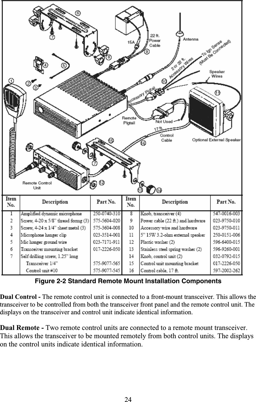
![30 Figure 2-7 Display Controller Board Figure 2-8 [not used] Audio PA Board The audio PA board has a 5-pin connector for connecting to the controller board. Table 2-1 Control Unit DIP Switch S1 Settings Configuration (see Section 2.6.1) Master/Slave Setting (S1-8/S1-9) [1] Volume Control Setting S1-2 [2] Front mount transceiver only Master* Don’t Care Remote control unit, single control Standard internal speaker used Optional external speaker used Master* Master* On* Don’t Care [5] Dual control, standard configuration [3] Front mount transceiver control unit Remote control unit Master* Slave Don’t Care On* Dual control, alternate configuration [4] Front mount transceiver control unit Remote control unit Slave Master* Don’t Care Don’t Care [5] Dual Remotes, internal speakers used Remote control unit 1 (either control unit) Remote control unit 2 (other control unit) Master* Slave On* On* Dual Remotes, one internal/one external speaker used Control unit controlling external speaker Remote control unit with internal speaker Master* Slave Don’t Care [5] On* Handheld Control Unit, Dual Controls, (HHC + front mount radio, single internal/external speaker available) Volume Controlling Unit Other Ctrl Unit Master* Slave N/A/Don’t Care N/A/Don’t Care](https://usermanual.wiki/E-F-Johnson/2424310.manual-part-1/User-Guide-520073-Page-30.png)
![31 Handheld Control Unit, Dual Remotes (HHC + remote control unit, two speakers available) HHC (controls external speaker) Remote control unit (controls int. speaker) Master* Slave N/A On* * - Default setting, no change usually required. [1] Master = S1-8 Off/S1- 9 On; Slave = S1-8 On/S1-9 Off [2] S1-3 is always On and S1-10 is always Off. Set using DIP switches S1-2, 3, and 10. [3] The volume of each internal speaker is controlled independently by the local volume control. If an external speaker is used, it is controlled by the front mount transceiver and the radio internal speaker is inactive. [4] This configuration allows an external speaker to be controlled by the remote control unit. However, both internal speakers and the volume control of the front mount transceiver are then inactive. [5] When a remote control unit controls an external speaker and the internal speaker is not used, disable the internal speaker by disconnecting the internal PA board from the display controller board (see Section 2.6.4). 2.6.3 SETTING MASTER/SLAVE SWITCHES With two control units, the control unit designated as the Master controls the external or front mount radio speaker. Switches 8 and 9 of DIP switch S1 on the display controller board (see Figure 2-7 or 2-8) set the Master/Slave configuration of the control unit as follows. This switches function the same on both boards. Set these switches as indicated in Table 2-1 if applicable. Master = SW 8 Off, SW 9 On (default) Slave = SW 8 On, SW 9 Off 2.6.4 CONFIGURING VOLUME CONTROL S1-2, 3, and 10 select the volume control mode. These switches can almost always be left in the default mode (S1-2 and 3 = On, S1-10 = Off). Additional information follows. • If controlling an external speaker and the internal speaker is not used, disable the internal speaker by disconnecting the control unit audio PA board from the controller board. • If controlling the local internal speaker when equipped with the unrevised audio PA board (hardwired to controller board), S1-2 = Off or R756 Out. 2.6.5 MOUNTING REMOTE CONTROL UNIT A diagram showing a remote transceiver installation is located in Figure 2-2. The control unit mounting bracket, 17-foot (5-meter) control cable, and mounting hardware are included. Proceed as follows:](https://usermanual.wiki/E-F-Johnson/2424310.manual-part-1/User-Guide-520073-Page-31.png)

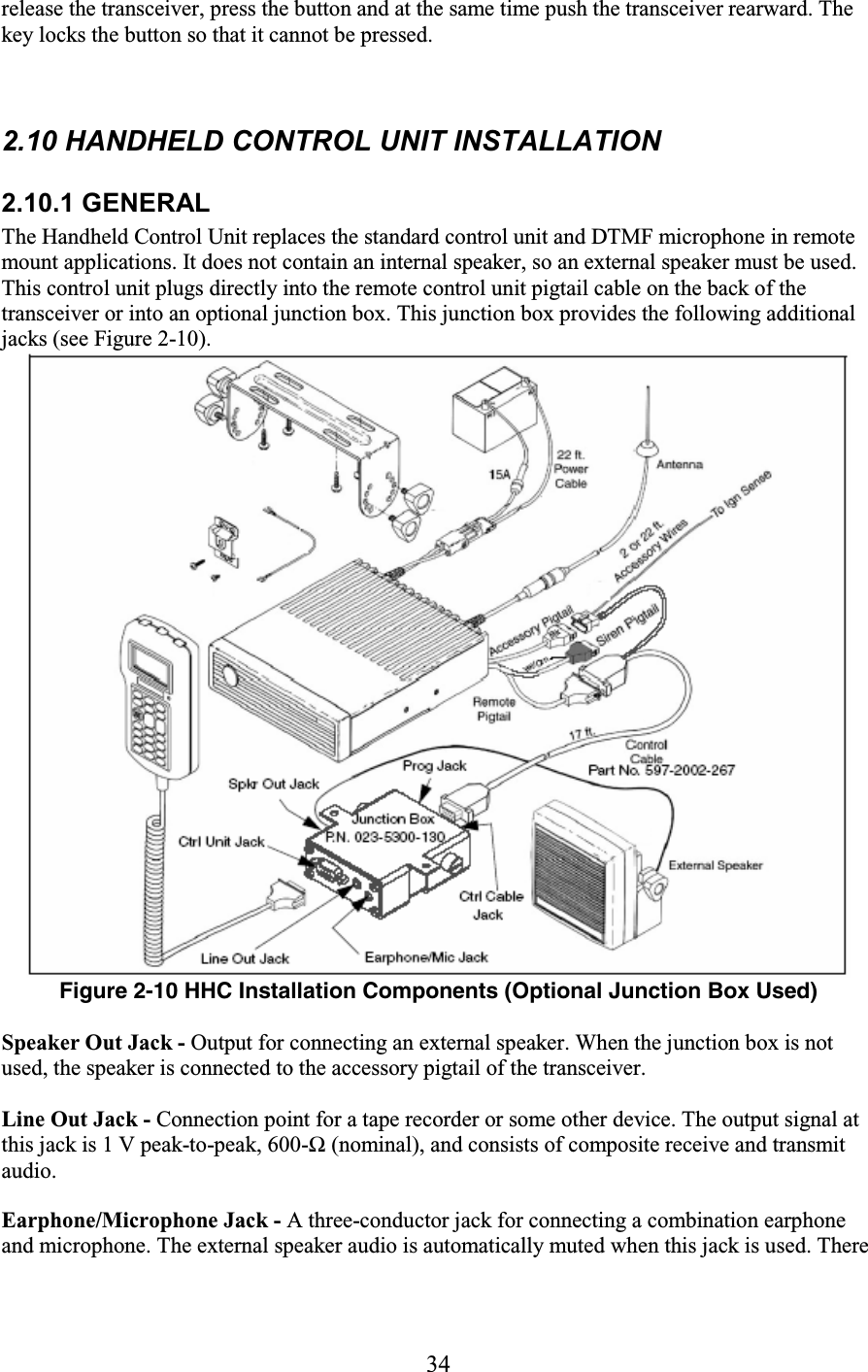
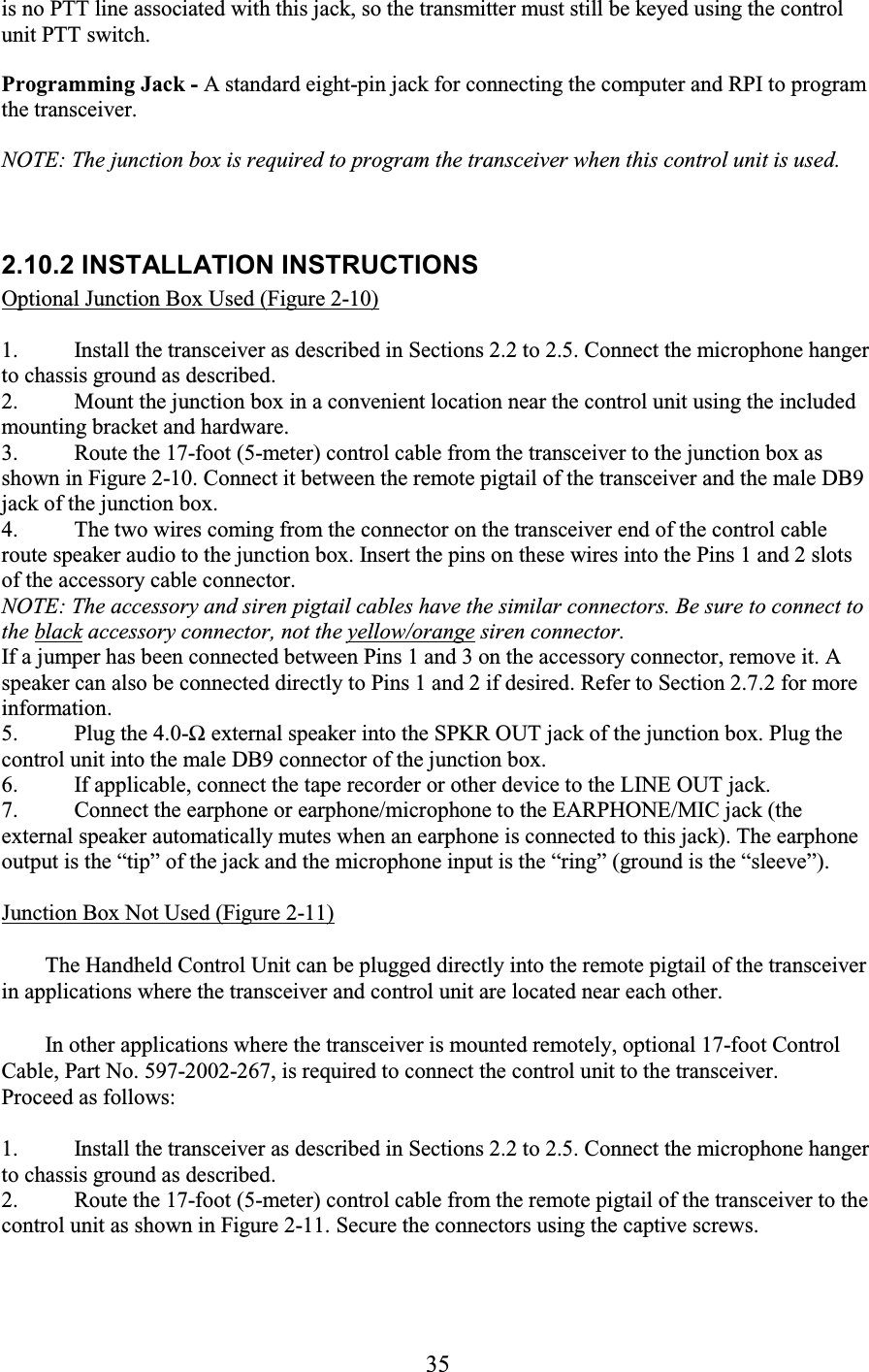
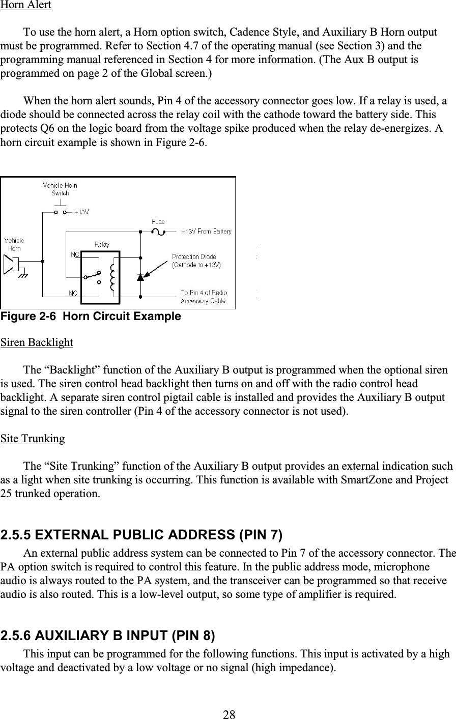
![37 The HHC is designated the Master and the remote control unit the Slave (see Section 2.6.3). The remote control unit volume control switches should be left in the default configuration (see Section 2.6.4). 2.10.4 TRANSCEIVER PROGRAMMING WITH HHC The programming setup used to program a transceiver equipped with the Handheld Control Unit is similar to that used with the standard control units. The programming cable is connected to the junction box using a special adapter. Refer to Section 4.1.4 for more information. Only one transceiver programming parameter must be changed when the Handheld Control Unit is used. Set the “Controller Type” parameter on the Global screen of the PCConfigure programming software for “Handheld” instead of “Normal”. 4. There is also a DIP programming switch on the handheld controller board. Generally, the ten switches of this switch should be left in the default position which is switches 2, 3, 6, and 9 “On”, and the others “Off”. The only time any of these switches may need to be changed is when the HHC is used in a dual control or dual remote configuration as described the preceding section. 2.11 SIREN OPTION INSTALLATION INSTRUCTIONS 2.11.1 GENERAL The 4300 Siren Kit, Part No. 250-5300-100 [What is the part number of the 4300 part?], contains a siren amplifier, siren controller, and all the cables and hardware normally required to install this option. This kit connects to an E.F. Johnson 4300 mobile transceiver. The siren loudspeaker is optional, and the following models are available: Part No. 585-5300-007 [What is the part number of the 4300 part?]- Model TS100 for light bar installation Part No. 585-5300-009 [What is the part number of the 4300 part?]- Model MS100 for compact (behind grille) installation. 2.11.2 TRANSCEIVER PROGRAMMING For proper operation of the siren controller backlight, a transceiver programming parameter may need to be changed. On the Global screen of the PCConfigure programming software (see Section 4), set the “Auxiliary B Toggle” parameter for “Backlight”. The Siren Control Head backlight then turns on and off with the transceiver control unit backlight. 2.11.3 INSTALLATION PROCEDURE Refer to Figure 2-12 and proceed as follows:](https://usermanual.wiki/E-F-Johnson/2424310.manual-part-1/User-Guide-520073-Page-37.png)
![38 Figure 2-12 Siren Installation Diagram 1. Mount the siren amplifier near the transceiver [the connecting cable to the transceiver is approximately 3 feet (0.9 meters) long]. 2. Mount the siren controller in the desired location [the connecting cable to the amplifier is approximately 22 feet (6.7 meters) long]. 3. Mount the siren loudspeaker in the desired location [the connecting cable to the amplifier is approximately 20 feet (6.1 meters) long]. Refer to the installation instructions included with the speaker for more information. 4. Connect the included 22-ft (6.7m) control cable assembly between the amplifier, transceiver, and controller as shown in Figure 2-12. Be sure to connect it to the yellow (or orange) 8-pin siren pigtail of the transceiver (not the black 8-pin accessory pigtail). NOTE: Connect the power cable directly to the vehicle battery. Connection to other locations may result in excessive noise in the audio signal when using the PA function. 5. Connect the included fuseholder to the positive (+) battery terminal using the included ring terminal or another connector as required. 6. Connect the included red cable from the +12V terminal on the amplifier to the fuseholder using the included solder splice connector. This connector contains internal solder that melts when heated sufficiently. 7. Connect the included black cable from GND terminal on the amplifier to the negative (–) battery terminal using the included ring terminal or some other connector as required. 8. Connect the loudspeaker to the SPEAKER terminals on the amplifier using the included 2-conductor cable and solder splice connectors (the order is not important).](https://usermanual.wiki/E-F-Johnson/2424310.manual-part-1/User-Guide-520073-Page-38.png)


![41 SECTION 4 TRANSCEIVER PROGRAMMING 4.1 GENERAL 4.1.1 PROGRAMMING SETUP The following items are required to program the transceiver. The part numbers of this equipment are shown in Table 1-1 in Section 1. The programming setup is shown above. • A Windows®-based computer (see next section) • Remote Programming Interface (RPI), Part No. 023-5300-000 • Programming cable from RPI to transceiver (see Section 4.1.3 for more information). • EFJohnson PCConfigure programming software, Part No. 023-9998-488. NOTE: The -005 cable, -000 RPI, -488 software, and a CD manual are included in the 5300 Series Programming Kit, Part No. 250-5000-004. [What are the part numbers of the 4300 parts?] 4.1.2 COMPUTER DESCRIPTION The computer used to program this transceiver should meet the following minimum requirements: . • Windows 95/98/NT/2000 (3.1 cannot be used) . • Pentium® processor or equivalent . • 16 MB of RAM . • A hard disk drive with at least 5 MB of free space](https://usermanual.wiki/E-F-Johnson/2424310.manual-part-1/User-Guide-520073-Page-41.png)
![42 . • A CD-ROM drive . • An available serial port 4.1.3 CONNECTING COMPUTER TO TRANSCEIVER NOTE: [What are the part numbers of the 4300 parts?] Only RPI, Part No. 023-5300-000, can be used to program the 5300-series transceiver. Other RPIs such as 023-9800-000 and 023-9750-000 are not compatible with this transceiver. Connecting RPI To Computer The Radio Programming Interface (RPI) provides the required logic interface between the computer and transceiver. The cable from the RPI to computer is not included with the RPI. The RPI has a female DB9 connector, and most computer serial ports have a male DB9 or DB25 connector. Therefore, a male DB9 to female DB9 or DB25 is usually required. This is a standard cable available at most computer supply stores or order 6 ft. DB9M to DB9F cable, Part No. 597-5900-002. Connecting RPI To Transceiver The programming setup for a front mount transceiver is shown in Figure 4-1. With transceivers that use the standard front or remote control unit, the cable from the RPI plugs into the microphone jack of the transceiver or control unit. This cable is Part No. 023-5300-005 [What is the part number of the 4300 part?], and it is not included with the RPI. Connecting the programming setup to the handheld controller is described in the next section. 4.1.4 HANDHELD CONTROLLER PROGRAMMING SETUP When the Handheld Control Unit is used (see Section 3), the same computer, RPI, and programming cable are used as with the standard front and remote models. In addition, the following components are required: • The junction box (Part No. 023-5300-130 [What is the part number of the 4300 part?]) is required to provide a connection point for the RPI since the control unit does not have a programming jack. This box may not be included with some handheld control units. • Adapter Plug, Part No. 023-5300-140 [What is the part number of the 4300 part?], is required to plug the 4300 programming cable into the rectangular 10-pin programming connector on the junction box (see following illustration). Programming Adapter Plug Only one transceiver programming parameter must be changed when the Handheld Control](https://usermanual.wiki/E-F-Johnson/2424310.manual-part-1/User-Guide-520073-Page-42.png)