E F Johnson 2425130 UHF Portable Radio User Manual 5100 Operating Manual
E. F. Johnson Company UHF Portable Radio 5100 Operating Manual
Operators Manual
DIGITAL/ANALOG PORTABLE RADIO
OPERATING
MANUAL
5100 SERIES
PORTABLE RADIO
VHF/UHF/800 MHZ
PROJECT 25 CONVENTIONAL
SMARTNET™/SMARTZONE®
7.2 VDC,
1 and 5 Watts (VHF);
1 and 4 Watts (UHF);
1 and 3 Watts (800 MHz)
Part No. 242-51xx-xxx
First Issue
May 2002
Supersedes: Part No.

2May 2002
Part No. 002-5100-100
SAFETY TRAINING INFORMATION
SAFETY TRAINING INFORMATION
WARNING
This radio produces RF electromagnetic energy when
transmitting and is designed and classified for “Occupa-
tional Use Only”. Radio equipment with this classifica-
tion must be used only during the course of employment
by individuals aware of the hazards and the ways to mini-
mize such hazards. This radio is NOT intended for use by
the General Population in an uncontrolled environment.
This radio has been tested and complies with FCC
RF exposure limits for “Occupational Use Only”. In
addition, it complies with the following standards and
guidelines with regard to RF energy and electromagnetic
energy levels and evaluation of such levels for exposure
to humans:
•FCC OET Bulletin 65 Edition 97-01 Supplement C,
Evaluating Compliance with FCC Guidelines for
Human Exposure to Radio Frequency Electromagnetic
Fields.
•American National Standards Institute (C95.1-1992),
IEEE Standard for Safety Levels with Respect to
Human Exposure to Radio Frequency Electromagnetic
Fields, 3 kHz to 300 GHz.
•American National Standards Institute (C95.3 -1992),
IEEE Recommended Practice for the Measurement of
Potentially Hazardous Electromagnetic Fields - RF
and Microwave. CAUTION
To ensure that your exposure to RF electromagnetic
energy is within the FCC allowable limits for occupa-
tional use, always adhere to the following guidelines:
•DO NOT operate the radio without the proper antenna
attached. This may damage the radio and cause FCC
RF exposure limits to be exceeded. The proper antenna
is the antenna supplied with the radio by the manufac-
turer or an antenna specifically authorized by the
manufacturer for use with this radio.
•DO NOT transmit more than 50% of total radio use
time (50% duty cycle). Transmitting for more than
50% of the time can cause FCC RF exposure compli-
ance requirements to be exceeded. This radio is trans-
mitting whenever the indicator on the front panel is red
continuously. Pressing the PTT switch on the side
usually causes the radio to transmit.
•DO NOT use any accessories not specifically autho-
rized by the E.F. Johnson Company for use with this
radio such as batteries, speaker-microphones, belt
clips, and antennas. The use of unauthorized accesso-
ries can cause FCC RF exposure compliance require-
ments to be exceeded.
•ALWAYS keep the antenna and radio at least 2.54 cm
(1.0 inch) away from your body when transmitting to
ensure FCC RF exposure compliance requirements are
not exceeded. The best transmission quality results
when the antenna is at least 5 cm (2 inches) away from
your mouth and angled slightly to one side.
•This unit has not been tested for FCC RF exposure
compliance in applications where the unit is transmit-
ting while body worn on the belt clip. This product is
not intended for use in applications where transmis-
sions are required while the unit is body worn with the
use of the belt clip.
NOTE: The preceding information is provided to make
you aware of RF exposure and what to do to ensure that
this radio is operated within FCC RF exposure limits.
Electromagnetic Interference/Usage
Compatibility
This device complies with Part 15 of the FCC rules.
Operation is subject to the condition that this device does
not cause harmful interference. In addition, changes or
modification to this equipment not expressly approved
by the E.F. Johnson Company could void the user’s
authority to operate this equipment (FCC Rules, 47CFR
Part 15.19).
DO NOT operate it in areas that are sensitive to RF
energy such as aircraft, hospitals, blasting sites, and fuel
storage sites. Areas with potentially flammable atmo-
spheres are usually, but not always, clearly posted. These
may include gas stations, fuel and chemical storage and
transfer stations, below deck on boats, and areas where
the air contains flammable chemicals or particles such as
grain dust or metal powders.
Dispose of the nickel metal-hydride (NiMH) or
nickel-cadmium (NiCd) battery used by this radio in
accordance with local regulations. DO NOT dispose of it
in fire because it can explode. Also, do not short the
terminals because it may become very hot.

51xx SERIES PORTABLE
OPERATING MANUAL
VHF/UHF/800 MHz
PROJECT 25 (DIGITAL) AND ANALOG
SMARTNET™/SmartZone®
Copyright© 2002 by the E.F. Johnson Company
The E.F. Johnson Company, which was founded in 1923, provides wireless communication
systems solutions for public safety, government, and commercial customers. The company
designs, manufactures, and markets conventional and trunked radio systems, mobile and
portable subscriber radios, repeaters, and Project 25 digital radio products. E.F. Johnson is a
wholly owned subsidiary of Transcrypt International, Inc.
Viking Head/EFJohnson logo, Call Guard®, PCConfigure™, and PCTune™ are trademarks of
the E.F. Johnson Company. SMARTNET™, SmartZone®, SecureNet™, Call Alert™,
Enhanced Private Conversation™, and Private Conversation II™ are trademarks of Motorola,
Inc. All other company and/or product names used in this manual are trademarks and/or reg-
istered trademarks of their respective manufacturer. The IMBE™ voice coding technology
embodied in this product is protected by intellectual property rights including patent rights of
Digital Voice Systems, Inc.
LAND MOBILE PRODUCT WARRANTY - The manufacturer’s warranty statement for this
product is available from your product supplier or from E.F. Johnson Company, 299 Johnson
Avenue, Box 1249, Waseca, MN 56093-0514. Phone (507) 835-6222.
Information in this manual is subject to change without notice.

4May 2002
Part No. 002-5100-100
TABLE OF CONTENTS
TABLE OF CONTENTS
SAFETY TRAINING INFORMATION. . . . . . . . . . .2
FEATURES . . . . . . . . . . . . . . . . . . . . . . . . . . . . . . . . . . .5
General Features . . . . . . . . . . . . . . . . . . . . . . . . . . . . . .5
Conventional Features. . . . . . . . . . . . . . . . . . . . . . . . . .5
SMARTNET/SmartZone Features . . . . . . . . . . . . . . . .5
CONTROLS AND DISPLAY. . . . . . . . . . . . . . . . . . .6
Front Panel Controls . . . . . . . . . . . . . . . . . . . . . . . . . . .6
Top Panel Controls . . . . . . . . . . . . . . . . . . . . . . . . . . . .7
Side Controls . . . . . . . . . . . . . . . . . . . . . . . . . . . . . . . . .7
Display. . . . . . . . . . . . . . . . . . . . . . . . . . . . . . . . . . . . . .8
GENERAL OPERATION . . . . . . . . . . . . . . . . . . . . . .8
Turning Power On. . . . . . . . . . . . . . . . . . . . . . . . . . . . .8
Setting Volume . . . . . . . . . . . . . . . . . . . . . . . . . . . . . . .8
Power-Up Password . . . . . . . . . . . . . . . . . . . . . . . . . . .9
Zone And Channel Select . . . . . . . . . . . . . . . . . . . . . . .9
Low Battery Indication . . . . . . . . . . . . . . . . . . . . . . . . .9
Backlight . . . . . . . . . . . . . . . . . . . . . . . . . . . . . . . . . . . .9
Keypad Lock . . . . . . . . . . . . . . . . . . . . . . . . . . . . . . . . .9
Setting Squelch . . . . . . . . . . . . . . . . . . . . . . . . . . . . . .10
Transceiver Operating Modes . . . . . . . . . . . . . . . . . . .10
Conventional Operating Mode . . . . . . . . . . . . . . . 10
SMARTNET/SmartZone Operating Mode. . . . . . 10
Secure Communication . . . . . . . . . . . . . . . . . . . . . . .10
Encryption (Hardware) Keys . . . . . . . . . . . . . . . . 11
RADIO-WIDE FEATURES. . . . . . . . . . . . . . . . . . . .11
Option Keys. . . . . . . . . . . . . . . . . . . . . . . . . . . . . . . . . 11
Menu Mode . . . . . . . . . . . . . . . . . . . . . . . . . . . . . . . . .11
Time-Out Timer. . . . . . . . . . . . . . . . . . . . . . . . . . . . . .12
Home Zone Select . . . . . . . . . . . . . . . . . . . . . . . . . . . .13
Power Output Select . . . . . . . . . . . . . . . . . . . . . . . . . . 13
Alert Tone Select. . . . . . . . . . . . . . . . . . . . . . . . . . . . .13
Scanning . . . . . . . . . . . . . . . . . . . . . . . . . . . . . . . . . . .13
Standard Scanning. . . . . . . . . . . . . . . . . . . . . . . . . 13
Radio Wide Scanning . . . . . . . . . . . . . . . . . . . . . . 13
Scan Resume Delay. . . . . . . . . . . . . . . . . . . . . . . . 14
Transmitting in the Scan Mode. . . . . . . . . . . . . . . 14
Nuisance Channel Add/Delete . . . . . . . . . . . . . . . 14
Scan Lists. . . . . . . . . . . . . . . . . . . . . . . . . . . . . . . . . . .14
Radio Wide Scan List . . . . . . . . . . . . . . . . . . . . . . 14
Standard Mode Scan Lists. . . . . . . . . . . . . . . . . . . 14
Determining Which Channels are in Scan List. . . 14
Selecting a Scan List. . . . . . . . . . . . . . . . . . . . . . . 15
Programming a Scan List . . . . . . . . . . . . . . . . . . . 15
CONVENTIONAL MODE FEATURES . . . . . . . .16
Monitoring Before Transmitting . . . . . . . . . . . . . . . . .16
Automatic Channel Monitoring . . . . . . . . . . . . . . 16
Manual Channel Monitoring. . . . . . . . . . . . . . . . . 16
Monitor Mode . . . . . . . . . . . . . . . . . . . . . . . . . . . . . . .16
Busy Channel Lockout . . . . . . . . . . . . . . . . . . . . . . . .16
Call Guard Squelch . . . . . . . . . . . . . . . . . . . . . . . . . . .17
Call Guard Squelch Enable/Disable. . . . . . . . . . . . 17
Selective Squelch Code Select. . . . . . . . . . . . . . . . 17
Penalty Timer . . . . . . . . . . . . . . . . . . . . . . . . . . . . . . . 17
Conversation Timer . . . . . . . . . . . . . . . . . . . . . . . . . . 18
Repeater Talk-Around . . . . . . . . . . . . . . . . . . . . . . . . 18
Displaying Transmit and Receive Frequency . . . . . . 18
Emergency Mode . . . . . . . . . . . . . . . . . . . . . . . . . . . . 18
Conventional Mode Scanning . . . . . . . . . . . . . . . . . . 18
Priority Channel Sampling . . . . . . . . . . . . . . . . . . . . . 18
Changing the Priority Channel. . . . . . . . . . . . . . . . 19
Placing and Receiving Conventional Calls . . . . . . . . 19
Project 25 (Digital) Mode Features . . . . . . . . . . . . . . 19
Viewing Individual ID. . . . . . . . . . . . . . . . . . . . . . 19
Group IDs. . . . . . . . . . . . . . . . . . . . . . . . . . . . . . . . 19
Selective Squelch. . . . . . . . . . . . . . . . . . . . . . . . . . 19
Changing Talk Group Assigned To A Channel. . . 19
Unit Calls . . . . . . . . . . . . . . . . . . . . . . . . . . . . . . . . 20
Keypad Programming. . . . . . . . . . . . . . . . . . . . . . . . . 20
Menu Structure. . . . . . . . . . . . . . . . . . . . . . . . . . . . 20
Zone Password. . . . . . . . . . . . . . . . . . . . . . . . . . . . 21
Zone Change Parameter. . . . . . . . . . . . . . . . . . . . . 21
Channel Change Parameter . . . . . . . . . . . . . . . . . . 21
System Parameters. . . . . . . . . . . . . . . . . . . . . . . . . 21
Channel Parameters . . . . . . . . . . . . . . . . . . . . . . . . 22
SMARTNET/SMARTZONE FEATURES . . . . . . 23
Viewing Unit ID. . . . . . . . . . . . . . . . . . . . . . . . . . . . . 23
Placing and Receiving Standard Group Calls . . . . . . 23
Private (Unit-To-Unit) Calls . . . . . . . . . . . . . . . . . . . 24
General. . . . . . . . . . . . . . . . . . . . . . . . . . . . . . . . . . 24
Placing an Enhanced Private Conversation Call . . 24
Placing a Private Conversation II Call. . . . . . . . . . 25
Receiving a Private Call (All Types) . . . . . . . . . . . 25
Placing and Receiving Telephone Calls. . . . . . . . . . . 26
Call Alert . . . . . . . . . . . . . . . . . . . . . . . . . . . . . . . . . . 27
Answering a Page. . . . . . . . . . . . . . . . . . . . . . . . . . 27
Initiating a Page . . . . . . . . . . . . . . . . . . . . . . . . . . . 27
Messaging. . . . . . . . . . . . . . . . . . . . . . . . . . . . . . . . . . 28
Sending Status Conditions . . . . . . . . . . . . . . . . . . . . . 28
Emergency Alarm and Call . . . . . . . . . . . . . . . . . . . . 28
Failsoft Operation. . . . . . . . . . . . . . . . . . . . . . . . . . . . 29
SMARTNET/SmartZone Scanning . . . . . . . . . . . . . . 29
Dynamic Regrouping . . . . . . . . . . . . . . . . . . . . . . . . . 29
SmartZone Features . . . . . . . . . . . . . . . . . . . . . . . . . . 30
Busy Override . . . . . . . . . . . . . . . . . . . . . . . . . . . . 30
Determining Current Site/Searching For New Site 30
Locking/Unlocking a Site . . . . . . . . . . . . . . . . . . . 30
SUPERVISORY TONES . . . . . . . . . . . . . . . . . . . . 30
INDEX . . . . . . . . . . . . . . . . . . . . . . . . . . . . . . . . . . . . . . 32

5May 2002
Part No. 002-5100-100
FEATURES
FEATURES
General Features
•The following operating modes are programmable:
– Conventional analog
– Conventional Project 25 (digital)
– SMARTNET™/SmartZone® trunked
•Up to 500 channels/talk groups programmable
•Zone select
•Large graphic display with backlight
•Up to 9 (limited keypad) or 21 (DTMF keypad)
programmable option keys
•Menu mode
•Standard and radio-wide scan modes
•User selectable and editable scan lists
•Time-out timer
•User selectable high and low power output
•Keypad lock
•Power-up password to prevent unauthorized use
Conventional Features
•Repeater talk-around
•Monitor mode selectable by option key or menu
•Carrier or Call Guard® (CTCSS/DCS) controlled
squelch on analog channels. Carrier, NAC and talk
group IDs on digital channels.
•Penalty and conversation timers
•Priority channel sampling when scanning
•Busy channel lockout (transmit disable on busy)
•DES-OFB encryption available (P25 channels)
•Unit (Individual ID) calls on Project 25 channels
•Keypad programming (Fed Gov. users only)
•Emergency key (Project 25 channels)
SMARTNET/SmartZone Features
•Group, Enhanced Private Conversation™, Private
Conversation II™, and Telephone Calls
•Emergency alarms to alert a dispatcher of
emergency conditions
•Emergency calls for high priority system access
•Failsoft operation on a predefined conventional
channel if trunked system fails
•Priority group calls detected while listening to other
group calls
•Call Alert™ (send and receive pages)
•Predefined messages (up to 16) can be sent to a
dispatcher
•Predefined status conditions (up to 8) can be sent to
a dispatcher
•Dynamic regrouping (dispatcher can automatically
gather users on a channel to receive a message)
•Roaming (SmartZone only)
•SecureNet™ secure communication available
NOTE: The availability of many of the preceding fea-
tures is determined by system operator programming
of your transceiver, installed options, and the capabili-
ties of the radio system being accessed.
6May 2002
Part No. 002-5100-100
CONTROLS AND DISPLAY
CONTROLS AND DISPLAY
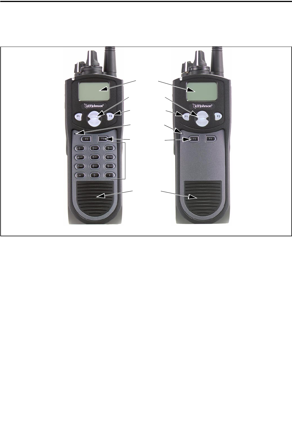
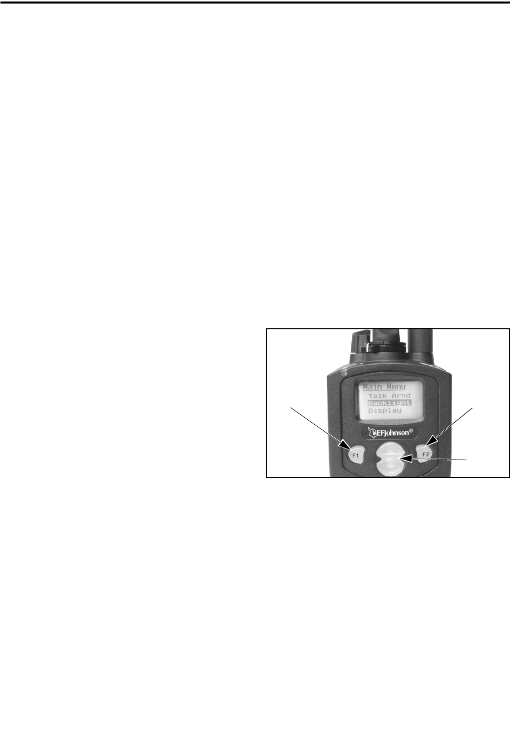
Figure 1 Front Panel Controls
Speaker
Display
DTMF Keypad
Option Keys
Microphone
DTMF Keypad Model Limited Keypad Model
Up/Down Sw
Menu/Option
Keys
F1 = Exit
In Various Modes:
F2 = Select/Menu
Enable
Front Panel Controls
NOTE: The following controls are shown in Figure 1.
Microphone - The microphone is located in this area.
For best results, hold the transceiver 2-3 inches from
you mouth and speak at a normal conversational level.
Display - This is a graphical LCD (Liquid Crystal
Display). The display backlight can be programmed to
turn on when any key is pressed or when the Backlight
option key is pressed (see page 9).
Up/Down Switch - Selects zones when multiple zones
are programmed. Pressing the upper part of the switch
selects the next higher number and pressing the lower
part selects the next lower number. This control also
provides up/down select in the menu mode and in
other modes when up/down select is required.
F1 - In menu mode, functions as a step back and exit
key. If menu mode is not used, it is a programmable
option key.
F2 - Selects the menu mode when that mode is
enabled by programming. Also functions as an Enter
or Select key in the menu and other modes. If menu
mode is not used, it is a programmable option key.
F3, F4 - Programmable option keys.
DTMF Keypad - The full keypad DTMF models
include the 12 keys required to dial telephone and unit
ID numbers.
Speaker - The transceiver speaker is located near the
bottom of the front panel. When a speaker/microphone
is used, this speaker is automatically disabled.
CONTROLS AND DISPLAY
7May 2002
Part No. 002-5100-100
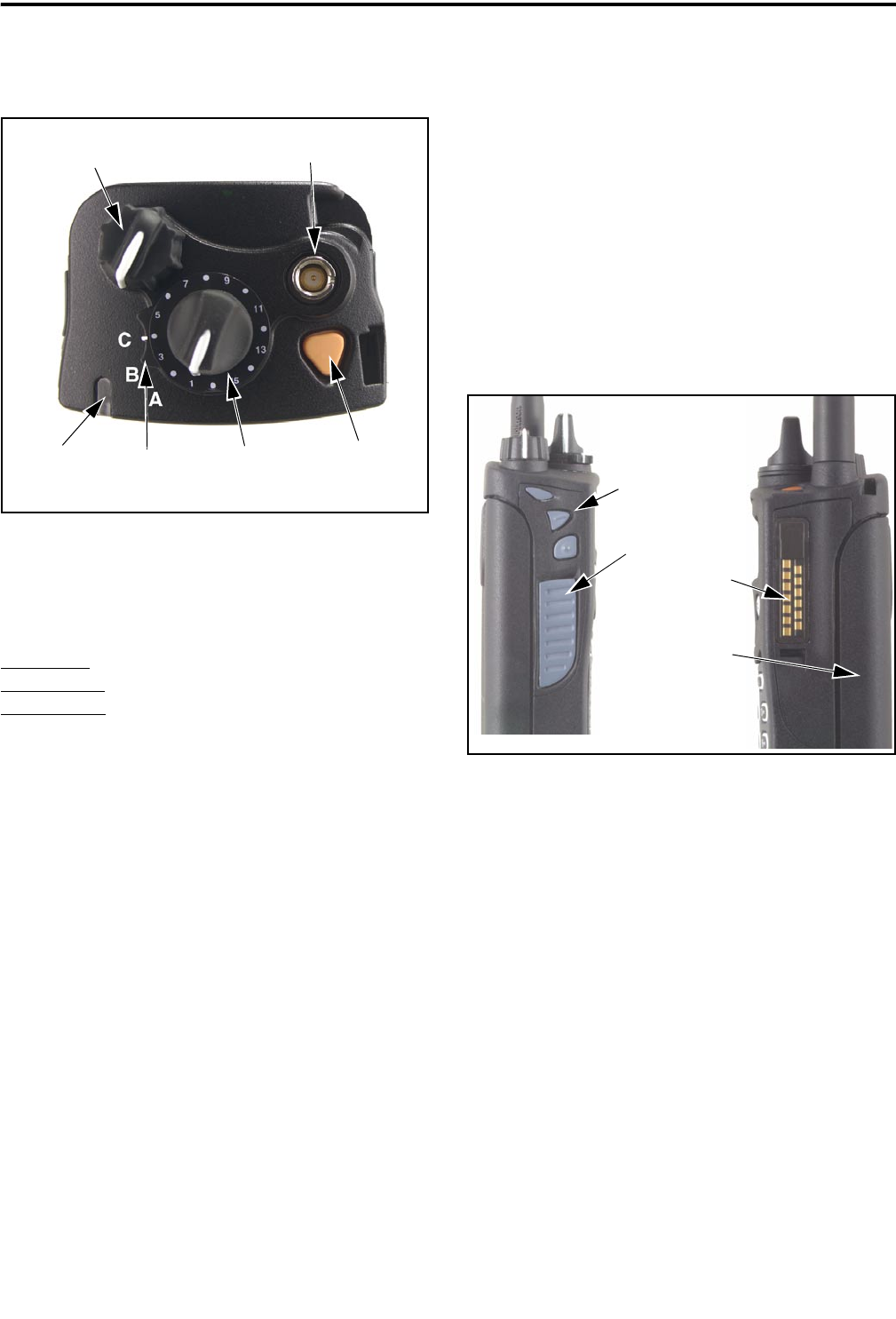
Top Panel Controls
Figure 2 Top Panel Controls
Multi-Function Indicator - Indicates the following
conditions:
Steady Red - Transmitter keyed.
Flashing Red - Low battery in receive mode.
Steady Green - Carrier detected in receive mode.
On-Off/Volume - Turning the knob clockwise turns
power on and sets the volume level. Turning it coun-
terclockwise to the detent turns power off. The
minimum volume level can be set by programming.
Channel Switch - This 16-position switch selects up
to 16 channels in the current zone. Additional zones
can be programmed to allow up to 500 channels to be
selected by this switch.
Rotary Option Switch - This is a three-position
switch that can be programmed to control various
options. The “A” and “B” positions are “off” and “on”,
respectively, and the “C” position is not used (see
page 11).
Antenna Connector - Connection point for the
antenna. Make sure the antenna is tight before using
the radio.
Emergency Key - This key or some other option key
can be programmed as an Emergency key to alert a
dispatcher of an emergency condition. Refer to pages
18 and 28 for more information. This key can also be
programmed for other functions.
Side Controls
Figure 3 Side Controls and Jacks
PTT (Push-To-Talk) Switch - This switch is pressed
to turn the transmitter to transmit a message. It is then
released to listen. Transmitting is indicated when the
top panel indicator is constant red.
Option Keys 1, 2, and 3 - Each of these keys can be
system operator programmed to control a specific
function (see page 11).
Battery - To remove the battery, press the release
button on the bottom and rotate the bottom of the
battery outward.
Accessory Connector - Connection point for optional
accessories such as a speaker/microphone or earphone.
Emergency
(Option)
Power On-Off/
Volume Adj
Channel
Switch
Antenna
Connector
Option
Switch Key
Multi-Function
Indicator
Option Keys
PTT Switch
Battery Pack
Accessory
Connector
1
2
3
GENERAL OPERATION
8May 2002
Part No. 002-5100-100
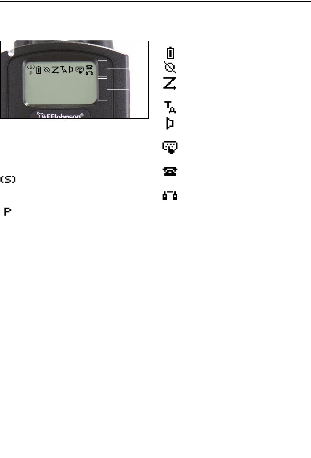
Display
Figure 4 Graphical Display
The front panel display is shown above. Icons are
typically shown in the upper part of the display and
text messages in the lower part. The default icons are
as follows:
- When the scan or the scan list edit mode is
enabled, indicates that the displayed channel is in the
scan list and scanned normally (see page 14).
- When the scan or the scan list edit mode is
enabled, indicates that the displayed channel is a
priority channel.
- Low battery indication (see page 9).
- Voice encryption is enabled (see page 10).
- Standard or radio wide scanning is enabled
(see page 13).
- Repeater talk-around is enabled (see page 18).
- Monitor mode is enabled by the Monitor
option key or menu parameter (see page 16).
- Keypad programming or another mode is
enabled which allows the user to edit radio parameters.
- A SMARTNET/SmartZone interconnect (tele-
phone) call is in progress (see page 26).
- A Project 25 or SMARTNET/SmartZone
private (unit-to-unit) call is in progress.
GENERAL OPERATION
Turning Power On
Power is turned on and off by the top panel On-
Off/Volume switch. When power is initially turned on,
the transceiver goes through a self test routine in
which the following information is displayed:
•Currently selected zone
•Individual ID of the radio if a conventional P25
channel is selected
•Unit ID of the radio if a SMARTNET/SmartZone
channel is selected
•Selected channel alias (last)
Programming determines if the transceiver
powers up on the last selected zone or the pre-
programmed home zone. The last selected channel of
the displayed zone is always selected on power up.
Setting Volume
The relative volume level can be determined by
the position of the index on the volume knob or a
reference tone as follows. The minimum volume level
may be set by programming. This can prevent missed
messages resulting from inadvertently turning the
volume to an inaudible level.
•If a key press tone is enabled, a short tone sounds
when a key is pressed.
•If a conventional channel is selected and the
Monitor option key or menu parameter is
programmed, pressing that key unsquelches the
receiver and either voice or background noise is
heard (see page 16). If a SMARTNET/SmartZone
channel is selected, the receiver cannot be manually
unsquelched.
Icon
Area
Text
Area

GENERAL OPERATION
9May 2002
Part No. 002-5100-100
Power-Up Password
The power-up password feature prevents unau-
thorized use of the transceiver by locking the keypad
on power up until the proper password is entered. This
feature is enabled or disabled by programming.
When it is enabled, “ENTER PSWD” is briefly
displayed when power is turned on. The eight-digit
numeric password must be then be entered as follows.
If an incorrect password is entered, “INCORRECT” is
displayed and it must be re-entered.
DTMF Keypad Models - Enter the password using
the 0-9 keys and then press the Enter (F2) key when
finished. If a mistake is made, the last digit can be
erased by pressing the F1 (Clear) key.
Limited Keypad Models - Select the proper number
for each position by pressing the Up/Down switch.
When the proper number for a position is displayed,
select it and move on to the next position by pressing
the F2 (Enter) key.
Zone And Channel Select
Zone Select
The front panel Up/Down switch changes and
displays the current zone. When not in special modes
such as the menu mode, pressing either the top or
bottom part of this switch once displays the current
zone number as “Zone x”. Then quickly pressing it
again changes the selected zone up or down.
After the highest programmed zone is displayed,
wrap-around to the lowest programmed zone occurs
and vice versa. The selected zone is also displayed
briefly on power up.
Channel Select
Channels are selected by the rotary 16-position
switch on the top panel. The alias (identification) for
the selected channel/group is displayed continuously
during normal operation.
When an unprogrammed channel is selected,
“UNPROGRAMD” is displayed and a tone sounds (if
tones are enabled). When conventional channels are
selected and the Display Information option key or
menu parameter is programmed, either the channel
frequency or alias can be displayed (see page 18).
Low Battery Indication
NOTE: If the transceiver contains hardware (encryp-
tion) keys, be sure to reattach a battery within approxi-
mately one minute to prevent the loss of these keys.
A low-battery condition is indicated by the
icon in the display. The battery should be recharged or
replaced as soon as practical after this indication
appears. Once this indication appears, it stays on until
power is cycled.
The following additional low battery indications
and conditions may be enabled by programming:
•A chirp sounds once a minute in the standby and
transmit modes.
•A chirp sounds each time the PTT switch is pressed.
•Top panel LED indicator flashes red every 30
seconds in the receive mode.
•Low power is selected when transmitting.
As indicated in the preceding “Note”, the trans-
ceiver must be connected to a constant power source
to preserve the hardware (encryption) keys in memory.
Since these keys are maintained in memory for only
about 1 minute without a battery attached, be sure to
reattach a battery within that time if these keys are
used. Refer to see page 10 for more information on
encryption keys.
Backlight
The backlight for the display and option keys can
be programmed to automatically turn on when any key
is pressed. It then automatically turns off after a
programmed delay of 0-7.5 seconds so that battery
drain is minimized. If the Backlight option key or
menu parameter is programmed, it can be used to
manually turn the backlight on and off.
Keypad Lock
The Keypad Lock feature is used to temporarily
disable the front panel keys to prevent accidental key
presses. This feature is available if the Keypad Lock
option key is programmed.

GENERAL OPERATION
10 May 2002
Part No. 002-5100-100
To lock the keypad, simply press the Keypad
Lock option key. Then to unlock the keypad again,
press and hold this key until a tone sounds (approxi-
mately 1 second).
With DTMF keypad models, the DTMF keys can
also be totally disabled by programming on some or
all channels. The Keypad Lock feature then has no
affect on those keys.
Setting Squelch
This transceiver does not have a squelch control.
The squelch level is fixed and normally does not
require readjustment.
Transceiver Operating Modes
Introduction
Each selectable channel can be programmed for
either conventional or SMARTNET/SmartZone opera-
tion. For example, Zone 1/Channel 1 could be a
conventional channel, Zone 1/Channel 2 a
SMARTNET channel, and so on. Your system oper-
ator can tell you what type or types of operation are
programmed. Mode information on these modes
follows.
Conventional Operating Mode
This is a non-trunked operating protocol which
accesses independent radio channels. There is no auto-
matic access to several channels. Monitoring of the
channel before transmitting may not be automatic in
this mode, so you may have to do it manually to make
sure that it is not in use. Either analog or digital
(Project 25) signaling may be used. Operating features
unique to this mode are described starting on page 16.
SMARTNET/SmartZone Operating Mode
This is a trunked operating protocol that provides
automatic access to several channels. A “channel”
actually selects a talk group which is programmed
with one or more ID codes that determine what
mobiles are being called and what calls are received.
Monitoring is performed automatically, and special
tones and messages indicate busy and out-of-range
conditions. Enhanced features include roaming
(SmartZone only), telephone, private, and emergency
calls, Call Alert™, and messaging. Either analog or
digital signaling may be used. Operating features
unique to SMARTNET/SmartZone operation are
described starting on page 23.
When a SMARTNET or SmartZone channel is
selected or the radio is powered up on one of those
channels, it searches for a control channel. Once a
control channel is found, it attempts to register on the
radio system and the alias (name) of the selected
channel is displayed. If a control channel could not be
found (because of an out of range condition or the
system ID is not correct, for example), “NO SYS” or a
similar message is displayed and the radio continues to
search for a control channel.
The control channel transmits and receives
system information to and from all radios registered on
the system. Therefore, once a control channel is found,
it is continuously monitored for incoming call infor-
mation and is used to make call requests. The radio
automatically changes to a traffic channel to place and
receive calls and then returns to the control channel
when the call is complete.
Secure Communication
General
This transceiver may be optionally equipped to
provide secure communication on some or all chan-
nels. This feature encrypts your voice so that it can be
understood only by someone using a transceiver
equipped with a similar encryption device and encryp-
tion codes.
When a secure call is received or transmitted,
is indicated in the display. Secure communication
can be programmed on a per channel basis to operate
in various ways. If the current channel is programmed
to allow it to be selected, secure communication can
be manually enabled and disabled by the Clear/Secure
option key or menu parameter. In the receive mode,
secure calls may be auto detected or only calls coded
like the transmit signal may be received.
If the “Clear” mode is selected by Clear/Secure
key or menu parameter and an attempt is made to
RADIO-WIDE FEATURES
11 May 2002
Part No. 002-5100-100
transmit on a channel fixed in the “Secure” mode by
programming, “SEC ONLY” is displayed and trans-
mitting is not permitted. Conversely, if the “Secure”
mode is selected and the channel is fixed in the
“Clear” mode, “CLEAR ONLY” is displayed and
transmitting is not permitted.
If your transceiver has encryption, consult your
system operator for more information on how it func-
tions in your application.
Encryption (Hardware) Keys
NOTE: A nearly constant power source must be
applied to the radio to maintain the encryption keys in
memory. Therefore, when changing the battery, be sure
to reattach another battery within one minute. If it is
not, these keys may be lost and will need to be
reloaded again.
Each channel programmed for encryption has an
encryption key associated with it. Up to 16 keys can
be loaded into the radio, and the location from 0-15
refers to the “Hardware” location of the key. If more
than one key is loaded, the Hardware Key Select
option key may be programmed to select another key
for a channel. A new key selection remains in affect
until it is manually changed again. Select a hardware
key as follows:
1. Press the Hardware Key Select key or select that
menu parameter and HWKEY x is displayed (“x” is
the current key selection from 0-15).
2. Press the Up/Down switch to display the desired key
and then press the Hardware Key Select key again or
F2 key to select it and return to normal operation.
RADIO-WIDE FEATURES
Option Keys
Almost all the transceiver keys are programmable
unless they are dedicated to a specific function. These
keys can be programmed by your system operator for
one set of functions in the Conventional mode and
another in the SMARTNET/SmartZone mode as
described on page 10. Table 5 on page 12 lists the
programmable keys, the functions that can be
programmed in each mode, and the page of this
manual on which the function is described.
Menu Mode
Most functions that can be controlled by an
option key can also be controlled by the menu mode.
An exception is Keypad Lock which can be controlled
by an option key only. The functions that can be
controlled by the menu mode are also shown in Table
5 on page 12. Only parameters that apply to the
selected channel type (Conventional/SMARTNET/
SmartZone) are displayed.
When the menu mode is used, the F1 and F2 keys
become dedicated menu mode control keys: F1 is
Back/Clear, and F2 is Menu Select/Enter. If the menu
mode is disabled, these keys can be programmed for
other functions. The menu mode operates as follows:
1. To select the menu mode, press the F2 key. Up to
three menu parameters are then displayed as shown
in the preceding illustration.
2. To scroll up or down through the menu parameter
list, press the Up/Down switch. The selected
parameter is indicated by a dark bar.
3. To display the available modes for a highlighted
parameter, press the F2 key. The currently selected
mode is indicated by an asterisk.
NOTE: Some parameters cannot be selected with
scanning enabled.
Menu
Exit
Back/ Menu
Select/
Enter
Menu
Scroll
Up/Down

RADIO-WIDE FEATURES
12 May 2002
Part No. 002-5100-100
4. Press the Up/Down switch to highlight the desired
mode. Then select the F2 key to select that mode.
5. To step back to the previous level or exit the menu
mode, press the F1 (Clear) key.
Time-Out Timer
The time-out timer disables the transmitter if it is
keyed continuously for longer than the programmed
time. It can be programmed for times from 15 seconds
up to 3 minutes, 45 seconds or it can be disabled.
If the transmitter is keyed for longer than the
programmed time, the transmitter is disabled, a contin-
uous tone sounds, and “TX TIMEOUT” is displayed.
Five seconds before time-out occurs, a warning beep
sounds to indicate that time-out is approaching. The
timer and tone are reset by releasing the PTT switch. A
different time may be programmed on each channel.
Conventional channels can also be programmed
with a penalty timer which prevents transmissions for
a time after the transmitter is disabled by the time-out
timer. Refer to page 17 for more information.
Table 5 Programmable Option Key and Menu Mode Functions
Function Menu
Display
Available in Mode: See Description
on Page:
Conv. SMARTNET SmartZone
Alert tones On-Off Tones X X X 13
Backlight On-Off Backlight X X X 9
Call Alert Select X X 27
Call Response Select X X 24
Clear/Secure Select Security X X X 10
(Digital) Talk Group Select Select TG X 19
Display Information Select Display X 18
Emergency Select Emergency X X X 18, 28
High/Low Power Select Tx Power X X X 13
Home Zone Select Home Zone X X X 13
Key (Encryption) Select X X X 10
Keypad Lock Select (Opt sw only) X X X 9
Keypad Programming Select Keypad Prg X 20
Messaging X X 28
Monitor Mode Select Monitor X 16
Normal/Selective Select Squelch X 17
Phone Call Select X X 26
Priority Channel Select Priority X 18
Private Call Select X X 24
Radio Wide Scan Select X X X 13
Repeater Talk-Around Select Talk Arnd X 18
Scan Mode Select Scan X X X 13
Scan List Edit Select Scan Edit X X X 13
Scan List Select Scan Selct X X X 13
Selective Squelch Code Select Sqlch Code X 17
Site Lock Select X 30
Site Search Select X 30
Status Select X X 28
Unit Call Select Unit Call X 19
Unprogrammed (not used) - X X X -

RADIO-WIDE FEATURES
13 May 2002
Part No. 002-5100-100
Home Zone Select
If the Home Zone option key or menu parameter is
programmed, it can be used to quickly select the
preprogrammed home zone. The transceiver is also
programmed so that when power is turned on, the
home or last selected zone is automatically selected.
Power Output Select
If selectable power is allowed on the channel by
programming, the High/Low Power option key or
menu parameter can be used to select high or low
power. Low power increases battery life but may
decrease range and vice versa for high power.
The new level is flashed in the display as either
“HI POWER” or “LOW POWER”. If selectable
power is not permitted on the current channel,
“FIXED LOW” or “FIXED HIGH” is flashed and no
power change occurs. The selected power level on the
channel is permanent until it is manually changed
again.
Alert Tone Select
The various alert tones that sound are described
on page 30. These tones can be turned on and off if the
Alert Tone option key or Tones menu parameter is
programmed. When all tones are off, “TONE OFF” is
momentarily displayed, and when all tones are on,
“TONE ON” is momentarily displayed. If this key or
menu parameter is not programmed, tones are fixed in
the on or off mode by programming.
Scanning
Introduction
Scanning monitors the channels in the scan list
for messages that the transceiver is programmed to
receive. When a message is detected, scanning stops
and the message is received. Shortly after the message
is complete, scanning resumes (unless it has been
disabled).
There are two basic scan modes available: Stan-
dard and Radio Wide. The operation of the standard
type is unique to the type of channel selected, and the
operation of Radio Wide type is the same regardless of
the type of channel selected. Only one type can be
enabled at a time. For example, if standard scanning is
enabled and radio wide scanning is selected, standard
scanning is automatically disabled. More information
on these types of scanning follows.
Standard Scanning
Standard scanning monitors only channels that
are the same type as that currently selected. For
example, if a conventional channel is selected, only
conventional channels are scanned. Standard scanning
operates as follows:
•Enable scanning using the Scan option key or menu
parameter. Scanning is enabled when the icon
is displayed.
•To turn scanning off, press the Scan option key
again or select “Off” in the scan menu. Scanning is
disabled when the icon is no longer displayed.
•If the zone or channel is changed while scanning is
selected, scanning continues on the same or a
different scan list (see “Standard Mode Scan Lists”
on page 14).
Radio Wide Scanning
Radio wide scanning monitors the channels in the
radio-wide scan list. This scan list can include up to 16
channels of any type and assigned to any zone (see
“Radio Wide Scan List” on page 14). Radio wide
scanning is turned on and off by the Radio Wide Scan
option key or menu parameter as follows. If this key or
menu parameter is not programmed, radio wide scan-
ning is not available.
•Enable Radio Wide Scanning using the Radio Wide
Scan option key or menu parameter. As with stan-
dard scanning, radio wide scanning is indicated
when the icon is displayed.
•To turn radio wide scanning off, press the Radio
Wide Scan option key again or select “Off” in the
menu. Scanning is disabled when the icon is no
longer displayed.
•If the zone or channel is changed while radio wide
scanning, scanning continues normally.

RADIO-WIDE FEATURES
14 May 2002
Part No. 002-5100-100
Scan Resume Delay
When a message is received or transmitted while
scanning, there is a delay before scanning resumes.
The delay after receiving a call prevents another
message from being received before a response can be
made. The delay after transmitting a call ensures that a
response is heard instead of another message occurring
on some other channel.
Transmitting in the Scan Mode
When the transmitter is keyed while scanning is
enabled, the transmission may occur on the receive,
selected, or priority channel, depending on the oper-
ating mode and programming.
Nuisance Channel Add/Delete
With standard scanning, both conventional and
SMARTNET/SmartZone channels can be temporarily
deleted from the scan list, for example, if messages
become annoying. This feature is not available with
radio wide scanning. Channels can also be perma-
nently added or deleted from a scan list as described in
the next section. Proceed as follows to temporarily
delete a nuisance channel:
NOTE: The selected channel and also conventional
priority channels cannot be deleted from the scan list.
1. While receiving a message on the channel to be
deleted, press and hold the Scan option key until a
tone sounds (about 2 seconds).
2. The channel is then deleted and scanning of the
remaining channels in the scan list resumes.
3. Deleted channels are added back into the scan list if
any of the following occur:
•Scanning is turned off and then on again using the
Scan option key or menu parameter.
•Transceiver power is turned off and then on again.
•The selected channel is changed.
Scan Lists
Radio Wide Scan List
With radio wide scanning, there is only one scan
list available regardless of the type of channel selected,
and it is not user programmable. This scan list can
contain up to 16 channels of any type. For example, it
could include six conventional channels and ten
SMARTNET/SmartZone channels.
Standard Mode Scan Lists
NOTE: The selected channel is always scanned.
A scan list is simply the channels that are scanned
when scanning is selected. With conventional and
SMARTNET/SmartZone operation, several scan lists
can be programmed by your system operator, and each
list can include up to 16 channels/talk groups.
The channels/groups in a list are user program-
mable if the Scan Edit option key or menu parameter
is programmed. Refer to “Programming a Scan List”
which follows for more information.
The specific list that is scanned is user selectable
if the Scan (List) Select option key or menu parameter
is programmed. Refer to “Selecting a Scan List” which
follows for more information.
Determining Which Channels are in Scan List
The channels in the radio-wide and conventional
scan lists are indicated as follows. Channels in the
SMARTNET/SmartZone lists are indicated only when
editing a scan list.
1. To view the conventional scan list, enable standard
scanning using the Scan key or menu parameter.
Likewise, to view the radio wide scan list, enable
radio wide scanning using the Radio Wide Scan key
or menu parameter. Also select the scan list if appli-
cable as described in the following “Selecting a
Scan List” description.
2. Select the desired zone and then scroll through the
channels by rotating the channel switch. When the
displayed channel is in the scan list (scanned
normally), the icon is displayed.

RADIO-WIDE FEATURES
15 May 2002
Part No. 002-5100-100
Selecting a Scan List
Conventional Operation - The scan list is user select-
able if the Scan (List) Select option key or menu
parameter is programmed. Otherwise, it is a fixed list.
Changing a list with this option key or menu param-
eter is temporary since the programmed default list is
reselected at power up.
SMARTNET/SmartZone Operation - Each channel
(talk group) is programmed to select one of
programmed lists. In addition, each channel can be
programmed so that scanning is automatically enabled
or disabled (No List) when it is selected. If the Scan
(List) Select option key or menu parameter is
programmed, the list that is selected by all channels of
the current system can be temporarily changed. The
default list programmed for each channel is automati-
cally reselected at power up.
Select the scan list as follows:
1. With scanning disabled ( icon not displayed),
press the Scan List option key or select the Scan
Selct menu parameter.
2. The currently selected list is displayed as “List x”,
where “x” is the currently selected list. To exit
without changing the selected list, simply press the
Scan List option key again or the F1 or F2 key.
3. To select another list, press the Up/Down switch.
When the desired list is displayed, select it and exit
this mode by pressing the Scan List option key again
or the F2 key.
Programming a Scan List
If the Scan Edit option key or menu parameter is
programmed, conventional and SMARTNET/
SmartZone standard scan lists can be programmed as
follows. Changes are permanent (cycling power does
not reselect a default condition).
1. Make sure that both standard and radio wide scan-
ning are off ( icon not displayed). Select a
conventional or SMARTNET/SmartZone channel
corresponding to the scan list being programmed.
2. Select the scan edit mode using the Scan Edit option
key or menu parameter. This mode is indicated by
in the display.
3. If applicable, select the list to be edited by pressing
the Up/Down switch. Select the desired list by
pressing the F2 key. The selected list is indicated as
“LIST x”. If user programming is disabled on a list,
“NO EDIT” is momentarily displayed and it cannot
be edited.
4. Select the channel you want to add or delete by
pressing the Up/Down switch. After the last channel
in the current zone is displayed, the first valid
channel in the next zone is displayed and vice versa.
Lists are limited to 16 channels. If an attempt is
made to add more than 16, “LIST FULL” is
displayed and a channel must be deleted before
another can be added.
NOTE: A conventional priority channel cannot be
deleted (see page 18).
5. If the selected channel is in the scan list (scanned),
the icon is displayed. To change the status of
the displayed channel, press the F2 (Enter) key.
With conventional channels only, if the selected
scan list is programmed with a fixed priority
channel (see page 18), the next press of F2 makes
the current channel the priority channel. The
icon is then displayed to indicate that it is the
priority channel.
6. To exit this mode and save the changes, press the F1
(Exit) key or the Scan Edit option key again.

16 May 2002
Part No. 002-5100-100
CONVENTIONAL MODE FEATURES
CONVENTIONAL MODE FEATURES
Introduction
An overview of conventional operation is located
on page 10. The following information describes the
features unique to conventional operation, both analog
and digital (Project 25). Refer to the preceding
“Radio-Wide Features” section for information on
features common to all operating modes. Features
unique to SMARTNET/SmartZone operation are
described starting on page 23.
Monitoring Before Transmitting
Introduction
With conventional operation, you may need to
manually monitor the channel before transmitting to
make sure that it is not be used by someone else. If
your were to transmit while someone else is using the
channel, you would probably disrupt their conversa-
tion. With SMARTNET/SmartZone operation, moni-
toring is always performed automatically. Monitor
conventional channels automatically or manually as
follows:
Automatic Channel Monitoring
If the selected channel is programmed with the
Busy Channel Lockout feature (consult your system
operator), monitoring is performed automatically.
Refer to the description of this feature on page 16 for
more information.
Manual Channel Monitoring
The automatic monitoring just described may
occasionally disable the transmitter when the channel
is not in use. In this case, you may need to manually
monitor the channel as follows:
Busy Indicator - With scanning disabled, note if the
multi-function indicator on the front panel is steady
green. If it is not, the channel is not being used and a
call can be transmitted. It it is green, the channel may
be busy and a call should not be placed (see next para-
graph).
Monitor Mode - There may be times when a busy
condition is indicated even though no one is using the
channel. Monitoring should then be performed by
enabling the monitor mode described next. The
Normal/Selective function may also be used on analog
channels (see description on page 17).
Monitor Mode
The monitor mode temporarily disables squelch
control features (such as Call Guard squelch) and
unsquelches the receiver so that all activity on the
channel can be monitored. In addition, it overrides the
Busy Channel Lockout feature (see next section) and
temporarily disables scanning.
To select the monitor mode, briefly press the
Monitor option key or select the menu parameter. This
mode is indicated when is displayed. To disable the
monitor mode and return to normal operation, press
the Monitor option key again or select “Off” in the
menu mode.
This feature may also be useful during weak
signal conditions if intermittent squelching makes a
message difficult to understand. When scanning,
pressing and holding the option key until a tone
sounds monitors the scanned channel instead of the
selected channel (if it is different).
Busy Channel Lockout
The Busy Channel Lockout feature (also called
Transmit Disable on Busy) automatically disables the
transmitter if the channel is busy when the PTT switch
is pressed. When the transmitter is disabled by this
feature, “BUSY” is displayed, a busy tone sounds, and
the transmitter is disabled. Each channel is
programmed to operate in one of the following modes:
Off - Busy channel lockout is disabled and the trans-
mitter keys even if the channel is busy.
Noise - If any activity is detected on the channel, the
transmitter is disabled when the PTT switch is pressed.

CONVENTIONAL MODE FEATURES
17 May 2002
Part No. 002-5100-100
Tone (NAC) - If the detected Call Guard or NAC
(Project 25) squelch coding is incorrect, the trans-
mitter is disabled when the PTT switch is pressed.
If Busy Channel Override is permitted by
programming, it is possible to transmit when the trans-
mitter is disabled by this feature. Simply release and
then quickly press the push-to-talk (PTT) switch again.
Call Guard Squelch
Introduction
Call Guard squelch (also called CTCSS/DCS
signaling) can be programmed on conventional analog
channels. This feature eliminates distracting messages
intended for others using the channel. This is done by
using a subaudible tone or digital code to control the
squelch. This tone or code is unique to a user or a
group on that channel, and is transmitted by the mobile
placing a call. If Call Guard squelch is programmed in
the mobile receiving the call, it must detect the correct
tone or code to receive the call.
Call Guard Squelch Enable/Disable
The Normal/Selective option key or menu param-
eter (if programmed) can be used to disable receive
Call Guard squelch so that all calls are heard. When it
is disabled, “Sq Normal” is flashed in the display, and
when it is enabled, “Sq Select” is flashed.
The receiver unsquelches only if activity is
detected on the channel, and scanning is not disabled.
The selected mode is in effect until it is manually
changed again. Selecting another channel or cycling
power does not reselect a default condition.
When this function is used on a digital channel,
talk group detect is disabled, so calls to all groups are
heard. However, the correct NAC is still detected, so
calls with another NAC are not heard (see page 19).
Selective Squelch Code Select
A different CTCSS/DCS/NAC squelch code can
be temporarily selected if the Squelch Code option key
or menu parameter and a CTCSS/NAC code list have
been programmed. This feature allows the normal
transmit and receive Call Guard programming to be
temporarily overridden with a code selected from this
list.
This code list is programmed with up to sixteen
CTCSS and DCS codes for use on analog channels
plus up to sixteen NAC codes for use on digital
(Project 25) channels. When a selective squelch (Call
Guard) code is changed as describe below, it remains
selected even if other channels are selected. However,
if transceiver power is cycled or a talk-around channel
is selected, the normal codes are reselected.
When scanning, the selected code also applies to
all scanned channels. If both analog and digital chan-
nels can be selected or scanned, the CTCSS/DCS code
for the selected position is used for analog channels
and the NAC code for the selected position is used for
P25 channels. Proceed as follows to select a prepro-
grammed Call Guard code:
1. Press the Selective Squelch Code option key or
select the Sqlch Code menu mode parameter. Then
press the Up/Down switch to select the desired code.
The display indicates “SEL SQ xx” where, “xx” is
the selected code from 1-16.
2. To select the displayed code and return to the normal
display, press the F2 (Select) key or the Selective
Squelch key again.
3. To check which code is selected, press the Selective
Squelch key once to display the current selection
and then again to return to normal operation.
4. To return to the normal selective squelch codes,
select “DEFAULT” in this mode. As previously
described, the normal codes are also automatically
reselected whenever transceiver power is cycled or
a talk-around channel is selected.
Penalty Timer
A penalty timer may be programmed on conven-
tional systems to prevent transmissions for the
programmed time after the time-out timer disables the
transmitter (see page 12). The penalty timer can be
programmed for the same times as the time-out timer,
and timing starts when the PTT switch is released. If
the PTT switch is pressed during the penalty time, the
time-out indication occurs again and the transmitter

CONVENTIONAL MODE FEATURES
18 May 2002
Part No. 002-5100-100
does not key. When the penalty timer expires, a beep
sounds and the transmitter can be keyed.
Conversation Timer
A conversation timer can be programmed on
conventional systems in addition to the time-out timer
described on page 12. This timer limits the total length
of a conversation rather than just the length of each
transmission as with the time-out timer. More informa-
tion on this timer follows:
•It can be programmed for times up to 7.5 minutes.
•It is reset when the time between transmissions
exceeds the time programmed for the penalty timer
just described.
•A warning beep sounds 5 seconds before this timer
disables the transmitter.
•When this timer disables the transmitter, a contin-
uous tone sounds and the red transmit indicator
turns off. The PTT switch must then be released
until the penalty timer expires (indicated by a beep).
Repeater Talk-Around
Normally, all transmissions go through a repeater
which usually increases range. However, there may be
times when you are out of range of the repeater and
therefore unable to talk to anyone even though the
mobile being called is only a short distance away. To
allow communication in this situation, repeater talk-
around can be selected. Transmissions then occur on
the receive frequency which permits direct mobile-to-
mobile communication.
Repeater talk-around can be selected if the RTA
option key or menu parameter is programmed. When
talk-around is enabled by this key, is displayed.
This feature remains enabled during scanning, and the
selected mode does not change when another channel
is selected or power is cycled. Talk-around is available
on conventional channels only.
Displaying Transmit and Receive Frequency
If the Displayed Information option key or menu
parameter is programmed, it can be used to display the
channel frequency in megahertz. Pressing this key
toggles between displaying the standard channel alias
and the channel frequency. The receive frequency is
displayed when receiving and the transmit frequency is
displayed when transmitting. This feature is available
on conventional channels only.
Emergency Mode
The Emergency option key or menu parameter
can be programmed to alert a dispatcher or someone
else of an emergency condition. It is available on
conventional digital (Project 25) and/or SMARTNET/
SmartZone channels, but not conventional analog
channels. If you have this function, consult your
system operator for more information on how it is
used in your application.
Conventional Mode Scanning
Channel scanning features common to all oper-
ating modes are described starting on page 13. When
the transmitter is keyed with scanning enabled, the
transceiver can be programmed so that transmission
always occurs on one of the following channels:
•Selected channel
•Priority channel (see following)
•Channel of the call if a response is made before
scanning resumes.
Priority Channel Sampling
General
The priority channel sampling feature ensures
that messages on the priority channel are not missed
while listening to a message on some other channel.
The transceiver can be programmed so that the priority
channel is a fixed channel programmed in the current
scan list, the currently selected channel, or not used.
When scanning and the selected channel is a fixed
priority channel, is indicated in the display.
Priority channel sampling occurs only with stan-
dard conventional scanning. It does not occur with
radio-wide scanning, when listening to any type of
SMARTNET/SmartZone call, or when transmitting. A
series of “ticks” may be heard when the priority
channel is sampled while listening to a message on
some other conventional channel.

CONVENTIONAL MODE FEATURES
19 May 2002
Part No. 002-5100-100
Changing the Priority Channel
If a priority channel is associated with the current
scan list, it can be permanently changed using the
Priority option key or menu parameter as follows.
1. Make sure scanning is disabled ( icon not
displayed) and the desired scan list is selected (see
page 14).
2. Select the desired channel and then press the
Priority option key or select that menu parameter.
“Priority” is then flashed to indicate that the current
channel is now the priority channel when scanning
that list.
NOTE: The priority channel can also be changed
when editing a scan list as described on page 15.
Placing and Receiving Conventional Calls
Placing a Standard Conventional Call
1. Turn power on and set the volume as described on
page 8. Select the zone and channel programmed for
the mobile you want to call as described on page 9.
2. Monitor the channel automatically or manually as
described on page 16.
3. Press the PTT switch and if the Busy Channel
Lockout feature is programmed on the channel (see
page 16), the transmitter is automatically disabled if
the channel is busy. Otherwise, busy and out-of-
range conditions are not indicated.
4. Press (and hold) the PTT switch to talk and release
it to listen.
Receiving a Standard Conventional Call
1. Select or scan the channel programmed for the call
you want to receive (refer to pages 13 and 18 for
more scanning information).
2. When the call is received, press the PTT switch to
talk and release it to listen. If scanning, responses
may occur on the priority, selected, or receive
channel as described in the preceding information.
Project 25 (Digital) Mode Features
Viewing Individual ID
Each transceiver which operates on Project 25
(digital) channels is assigned an eight-digit individual
ID. When power is turned on with a Project 25 channel
selected, the individual ID of your radio is briefly
displayed.
Group IDs
Each Project 25 channel is programmed with a
group ID code that determines the group of mobiles
which will receive your call on that channel and also
which calls you can receive.
Selective Squelch
Project 25 conventional channels use a NAC
(Network Access Code) instead of Call Guard squelch
(see page 17) to control which calls are received on a
channel. Both the correct group ID and NAC must be
detected to receive a call. However, other operation,
such as monitoring, is similar to when Call Guard
squelch is used.
The NAC code can also be manually selected like
Call Guard codes if the Squelch Code option key and a
code list have been programmed. The procedure is the
same as that for Call Guard codes described on
page 17.
Changing Talk Group Assigned To A Channel
If the Digital Talk Group Select option key or
Select TG menu parameter is programmed, the talk
group assigned to a channel can be changed as
follows. The new talk group continues to be assigned
to the channel until it is manually changed again.
1. Select the channel to be changed and then press the
Talk Group Select option key or select the Select TG
menu parameter.
2. Press the Up/Down switch until the alias (alphatag)
of the desired talk group is displayed.
3. To select that talk group and return to normal oper-
ation, press the Talk Group Select option key again

CONVENTIONAL MODE FEATURES
20 May 2002
Part No. 002-5100-100
or the F2 key. If talk group selection has been
disabled on the channel by programming, “NO
LIST” is displayed, a tone sounds, and no change
occurs.
Unit Calls
Unit Calls (also called Individual Calls) can be
placed to a specific radio on a Project 25 channel if the
Unit Call option key or menu parameter is
programmed. This call differs from standard group
calls in that only one mobile instead of entire groups
of mobiles may receive the call. The mobiles that can
be called are preprogrammed by you system operator.
Proceed as follows to transmit and receive a Unit Call:
1. To transmit a unit call, press the Unit Call option key
or select the Unit Call menu parameter. The alias
(tag) of the last Unit Call is displayed.
2. If required, press the Up/Down switch to display the
desired call. The alias and ID of the unit calls that
have been programmed are alternately displayed.
3. Press the PTT switch and begin talking.
4. When a unit ID call is received, two beeps sound (if
tones are enabled), and “Call Rcvd” and the alias or
frequency of the currently selected talk group are
alternately flashed.
The transceiver may also be programmed to display
the alias of the channel on which the call is being
received (if it is not the same as the selected
channel) and/or the ID of the mobile placing the
call.
5. To respond, select the Unit Call mode by pressing
the Unit Call option key or selecting the menu
parameter. The following operation then occurs:
•If a unit call has been programmed with the ID of
the calling mobile, it is automatically selected. A
response can then be made without changing the
selected channel.
•If no Unit Call has been programmed with the ID
of the calling mobile, a response may have to be
made in the standard mode.
•If the call timer times out (set by programming) or
the channel is changed before a response is made,
the unit call mode is exited.
Keypad Programming
NOTE: The Keypad programming feature is available
to Federal Government users only. Users regulated by
the Federal Communications Commission are not
allowed to have this feature.
Introduction
Keypad programming is available on Federal
radios if the Keypad Programming option key or menu
parameter is programmed. It is then selected by simply
pressing that key or selecting that menu parameter.
The keypad programming mode is indicated by
“ZONE CHG” and in the display.
Keypad programming allows conventional
channel parameters such as the transmit and receive
frequency and Call Guard squelch code to be changed.
In addition, several conventional mode timers can be
changed. It cannot be used to reprogram disabled
channels or any SMARTNET/SmartZone information.
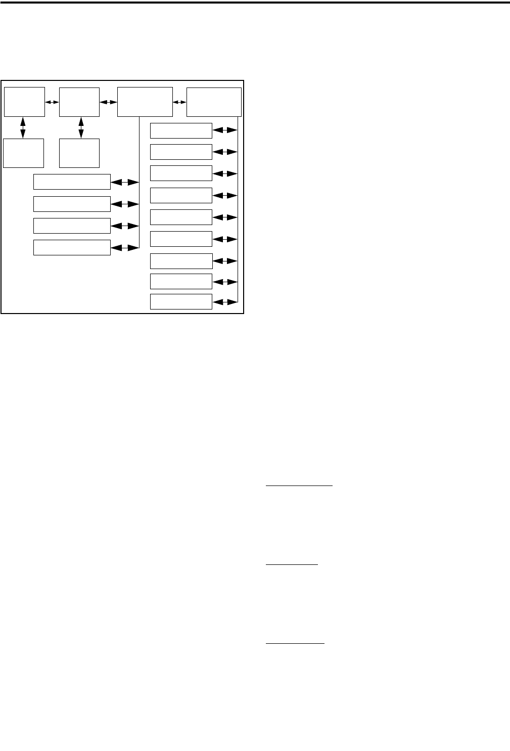
Menu Structure
A menu system is used to select parameters to be
changed in the keypad programming mode. A flow-
chart showing the keypad programming mode menu
structure is located in Figure 6.
When the keypad programming mode is selected
by the Keypad Programming option key or menu
parameter, the first menu parameter “CHNG ZONE”
is displayed as just described. Press the Up/Down
switch to scroll through the available parameters
which are listed below.
•CHNG ZONE
•CHNG CHAN
•SYS PARMS
•CHAN PARMS
Press the F2 (Select) key to select a highlighted
parameter, and press the F1 key from one of the main
menus to exit keypad programming. Pressing it in the
other menus returns to the previous menu. Information
CONVENTIONAL MODE FEATURES
21 May 2002
Part No. 002-5100-100
on the keypad programming parameters is located in
the following sections.
Figure 6 Keypad Programming Menu Flow-
chart
Zone Password
Each zone can be programmed so that the correct
password must then be entered before system or
channel parameters in that zone can be changed by
keypad programming. A different password can be
programmed for each zone.
When an attempt is made to select a system or
channel parameter in a password protected zone,
“ENTER PSWD” is displayed. The password is
always eight digits long and is entered using the same
procedure as used for the power-up password
described on page 9. After the password is entered,
system and channel parameters for that zone can be
reprogrammed normally.
Zone Change Parameter
The “CHG ZONE” menu parameter selects the
zone containing the conventional channel to be repro-
grammed. It does not change the zone selected for
normal operation.
Press the F2 key to select the “ZONE CHG”
parameter and then scroll through the programmed
zones by pressing the Up/Down switch. When the
desired zone is displayed, select it by pressing the F2
key.
Channel Change Parameter
The “CHNG CHAN” menu parameter selects the
conventional channel to be reprogrammed. Disabled or
SMARTNET/SmartZone channels cannot be selected.
This does not change the channel selected for normal
operation.
Press the F2 key to select the “CHNG CHAN”
parameter and then scroll through the programmed
channels by pressing the Up/Down switch. When the
desired channel is displayed, select it by pressing F2
key.
System Parameters
NOTE: If “ENTER PSWD” is briefly displayed when
attempting to select a parameter, see Zone Password
description on page 21.
The “SYS PARMS” menu parameter selects the
conventional mode timers to be reprogrammed (see
following). Press the F2 key to select the “SYS
PARMS” parameter and then press the Up/Down
switch to display the desired parameter. Then press the
F2 key again to select it.
SCAN TIMER - Selects the Scan Hold timer. Press the
Up/Down switch to decrement/increment the timer in
0.5-second steps, or set it to 0 seconds to disable it.
When the desired value is displayed, store it by
pressing the F2 key.
TX TIMER - Selects the transmit time-out timer. Press
the Up/Down switch to decrement/increment the timer
in 15-second steps, or disable it by selecting 0
seconds. When the desired value is displayed, store it
by pressing the F2 key.
PEN TIMER - Selects the penalty timer. Press the Up/
Down switch to decrement/increment the timer in 15-
second steps. When the desired value is displayed,
store it by pressing the F2 key.
Zone Channel
Change
Change System
Parameters Channel
Parameters
Select
Zone
Select
Channel
Scan Hold Timer
Tx Timer
Penalty Timer
Conver. Timer
Rx Freq
Tx Freq
Rx Code/NAC
Tx Code/NAC
Tx Power
Tx Tmr On-Off
Squelch Adj
Chan Spacing
F1 = Select
F2 = Exit/Back
Up/Down = Scroll
Tlk Grp Sel

CONVENTIONAL MODE FEATURES
22 May 2002
Part No. 002-5100-100
CONV TIMER - Selects the conversation timer. Press
the Up/Down switch to decrement/increment the timer
in 30-second steps, or disable it by selecting 0
seconds. When the desired value is displayed, store it
by pressing the F2 key.
Channel Parameters
NOTE: If “ENTER PSWD” is briefly displayed when
attempting to select a parameter, see Zone Password
description on page 21.
The “CHAN PARMS” menu parameter selects
the following conventional channel parameters that
can be reprogrammed. Press the F2 key to select the
“CHAN PARMS” parameter and then press the
Up/Down switch to display the desired parameter.
Then press the F2 key to select it. The squelch control
parameters are unique to the type of conventional
channel selected (analog or Project 25).
RX FREQ - Programs the receive channel frequency.
The digit being changed flashes, and press the Up/
Down switch to select the desired number for that
digit. Then press the F2 key to move to the next digit.
If an invalid frequency is entered, a beep sounds,
“INVALID” is briefly displayed, and the number must
be re-entered.
TX FREQ - Programs the transmit frequency the same
as RX FREQ above.
CTCSS/DCS Squelch Control (Analog Channel)
RX CODE - Programs the receive Call Guard
(CTCSS/DCS) code. The currently selected code is
initially displayed. Press the Up/Down switch to
select the desired code type (CTCSS analog or
DCS digital Call Guard). Then press F2 to select it
and enter the code number similar to programming
a channel frequency as just described.
TX CODE - Selects the transmit codes the same as
RX CODE above.
NAC Squelch Control (Project 25 Channel)
RX NAC - Programs the Network Access Code
(NAC) which can be any number from 0-4095. The
procedure is similar to programming a RX FREQ
just described. If an invalid code is entered, a beep
sounds, “INVALID” is briefly displayed, and the
code must be re-entered.
TX NAC - Selects the transmit NAC the same as
RX NAC above.
TX POWER - Selects the desired power output level.
Press the Up/Down switch to scroll through the
following choices. When the desired setting is
displayed, store it by pressing the F2 key.
•POWER HI - High transmit power
•POWER LO - Low transmit power
•POWER SW - Switchable power selectable by
the High/Low power key. This choice is not
available if that key is not programmed.
TX TIMER - Enables or disables the time-out timer on
the current channel. Press the Up/Down switch to
select the on and off mode, and when the desired
setting is displayed, store it by pressing the F2 key.
Analog Channel Parameters
CHAN SPC - Selects either wide or narrow band
channel spacing. Press the Up/Down switch to select
“WIDE” or “NARROW”, and when the desired
setting is displayed, store it by pressing the F2 key.
SQ ADJ - Changes the preset squelch setting on that
channel. The default setting is “0” and values of –7 to
+7 can be selected. Increasing this setting toward +7
causes the squelch to open sooner so that weaker
signals can be received, and decreasing it toward –7
causes the opposite to occur.
Digital (Project 25) Channel Parameters
NOTE: Channel spacing and squelch level cannot be
changed on digital channels.
TG (Talk Group) Select - Press the Up/Down switch to
display the alias of the desired talk group and then
store it by pressing the F2 key. If talk group selection
is not permitted on the channel by programming, the
talk group cannot be changed.

23 May 2002
Part No. 002-5100-100
SMARTNET/SMARTZONE FEATURES
SMARTNET/SMARTZONE FEATURES
Introduction
An overview of the SMARTNET/SmartZone
operating mode is located on page 10. The following
information describes the features unique to the
SMARTNET and SmartZone modes of operation.
Refer to the “Radio-Wide Features” section starting on
page 11 for information on features common to all
operating modes. Conventional mode features are
described in the preceding “Conventional Features”
section.
Viewing Unit ID
When power is turned on with a SMARTNET/
SmartZone channel selected, the six-digit Unit ID is
briefly displayed as IDxxxxxx.
Placing and Receiving Standard Group Calls
Standard calls are between you and another
mobile, group of mobiles, or a control station (a radio
in a fixed location). Most calls are probably this type.
Proceed as follows to place and receive these calls.
Placing a Standard Group Call
1. Turn power on and set the volume as described on
page 8. Select the zone and channel programmed for
the talk group you want to call (see page 9).
2. If encryption is used it may be automatically
selected. If not, select the Secure mode if desired by
by pressing the Clear/Secure option key or selecting
that menu parameter. The encryption status cannot
be changed if encryption is fixed on the talk group.
Refer to page 10 for more information on secure
communication.
3. Press the PTT switch and begin talking. A talk
permit tone may sound to indicate when talking can
begin. Events that may occur are as follows:
•If in the secure mode and your transceiver is not
programmed with the proper encryption key,
“KEYFAIL” is displayed and the call must be
made in the clear mode or the proper key must be
programmed.
•If the busy tone sounds and “BUSY” is displayed,
the system is busy. Release the PTT switch and
wait for the call back tone to sound. Then press
the PTT switch within 3 seconds.
•If a continuous tone sounds and “NO SYS” is
displayed, you may be out-of-range. Drive closer
or away from shielding objects and try again.
•If your unit ID is invalid, the call is being made to
an invalid group ID, group calls are not enabled,
or the selected talk group is not programmed for
the selected secure mode, “DISABLED ID” is
displayed and an alert tone sounds.
•If an attempt is made to change an analog call
from the clear to secure mode and there is no
available secure channel, “NO SEC” is flashed
and the call continues in the clear mode.
•If an attempt is made to change an analog channel
from the secure to clear mode, “SEC ONLY” is
displayed and the call continues in the secure
mode. (Calls on digital channels can be changed
if not strapped.)
•If the secure mode is selected by the Secure/Clear
option key or menu parameter and an attempt is
made to transmit on a channel strapped as clear,
“Clear Only” is displayed and the transmitter is
disabled. Conversely, if the clear mode is selected
and the channel is strapped as secure, “Secure
Only” is displayed and the transmitter is disabled.
Receiving a Standard Group Call
When a SMARTNET/SmartZone group call is
received, the transceiver can be programmed to
display the Individual ID of the calling mobile and/or
the received talk group alias. The Individual ID is
briefly displayed when the call is received and the talk
group and channel alias are then alternately displayed
(if applicable).

SMARTNET/SMARTZONE FEATURES
24 May 2002
Part No. 002-5100-100
Private (Unit-To-Unit) Calls
General
Private calls allow calls to be placed to a specific
mobile unit. Either the Enhanced Private Conversa-
tion™ or Private Conversation II™ modes may be
programmed depending on the capabilities of the radio
system. Operation in each of these modes is described
in the following information.
The Private Call option key is required to place
these calls, and either that key or the Call Response
option key is required to receive them. Private calls are
programmed to operate in one of the following modes:
•Disabled
•Answer-only capability
•List only - Unit IDs can be selected from a prepro-
grammed list only (direct entry using the keypad is
not allowed)
•Unlimited - Unit IDs can be selected from a list
and also dialed directly entered using the keypad.
Both limited and DTMF keypad models can place
private calls by recalling the unit ID from a prepro-
grammed list as just described. However, only DTMF
keypad models can directly dial unit IDs using the
keypad.
Placing an Enhanced Private Conversation Call
Recalling From List
1. Momentarily press the Private Call option key or
select that menu parameter and the alias of the last
called mobile is displayed. The private call mode is
indicated by in the display.
2. If required, select another mobile by pressing the
Up/Down switch until the alias of the desired
mobile is displayed.
3. Press the PTT switch to initiate the call.
(Proceed to the bulleted list which follows Item 3 in
the next section for events that may occur next.)
Direct Entry Using DTMF Keypad
1. Press and hold the Private Call option key until a
tone sounds (approximately 1 second). The last ID
called is displayed, and the private call mode is indi-
cated by in the display.
2. Using the 0-9 keys, dial the ID of the mobile you are
calling (all six digits). To erase the last digit, press
the F1 key, and to cancel the call, press the Private
Call Option key again.
3. Press the PTT switch to initiate the call. If the
entered number did not contain six digits,
“INVALID” is momentarily displayed, an error tone
may sound, and the call is not initiated.
If the entered number is valid, the display indicates
the alias of the ID if it matches an ID in the call list.
Otherwise, the ID you entered continues to be
displayed.
Events that may then occur are as follows:
•If the mobile being called is on the air, “WAIT” is
displayed and ringing is heard until the called
party answers or for 20 seconds, whichever occurs
first. When the call is answered, the voice of the
called party is heard.
•If the called mobile does not answer within 20
seconds, a continuous tone sounds and “NO ANS”
is displayed.
•If the called mobile is not on the air, a continuous
tone sounds instead of the ringing tone and “NO
ACK” is displayed.
•If the busy tone sounds and “BUSY” is displayed,
the called mobile has answered the call but the
system is busy. When the system is no longer busy,
the call back tone sounds.
•If your transceiver or the called transceiver is
inhibited or not programmed to make this type of
call or for the requested secure mode, “REJECT”
is displayed and an alert tone sounds.

SMARTNET/SMARTZONE FEATURES
25 May 2002
Part No. 002-5100-100
•If your transceiver does not have the proper
encryption key, “KEYFAIL” is displayed and the
call must be made in the clear mode by pressing
the Clear/Secure option key (if strapped to switch-
able). Otherwise, load the correct key.
4. When the call is finished or is not answered, end it
by pressing the Private Call option key or the F1
(Exit) key.
Placing a Private Conversation II Call
Recalling From List
1. Momentarily press the Private Call option key or
select that menu parameter. The alias of the last
called mobile is displayed, and the private call mode
is indicated by in the display.
2. If required, select another mobile by pressing the
Up/Down switch until the alias of the desired
mobile is displayed.
3. Press the PTT switch to initiate the call.
(Proceed to the bulleted list which follows Item 3 in
the next section for events that may occur next.)
Direct Entry Using DTMF Keypad
1. Press and hold the Private Call option key until a
tone sounds (approximately 1 second). The last ID
called is displayed, and the private call mode is indi-
cated by in the display.
2. Using the 0-9 keys, dial the ID of the mobile you are
calling (all six digits). To erase the last digit, press
the F1 key, and to cancel the call, press the Private
Call Option key again.
3. Press the PTT switch to initiate the call. If the
entered number did not contain six digits,
“INVALID” is momentarily displayed, an error tone
may sound, and the call is not initiated.
If the entered number is valid, the display indicates
the alias of the ID if it matches an ID in the call list.
Otherwise, the ID you entered continues to be
displayed.
Events that may then occur are as follows:
•The called party answers the call.
•The called party does not answer. Press the
Private Call option key or F1 (Exit) to end the
call.
•If the selected mobile ID is not valid, “INVALID”
is displayed and an alert tone sounds.
•If the radio system is busy, four low tones sound
and “BUSY” is displayed. When the system is no
longer busy, the call back tone (four beeps) is
heard and the channel is automatically acquired.
Press the PTT switch to continue the call.
•If the call is in the secure mode and the transceiver
does not have the proper encryption key,
“KEYFAIL” is displayed and the call must be
made in the clear mode by pressing the Clear/
Secure option key or selecting that menu param-
eter (if strapped to switchable). Otherwise, load
the correct key.
4. When the call is finished or if it is not answered, end
it by pressing the Private Call option key or the F1
(Exit) key.
Receiving a Private Call (All Types)
1. When a private call is received, “CALL” is
displayed and a recurring call tone sounds.
2. To answer the call, press the Private Call option key
or select that menu parameter and then press the
PTT switch and begin speaking. The unit ID of the
calling mobile is displayed. More information
follows:
•If the PTT switch is pressed before the Private Call
option key, the call is transmitted as a group call.
•If private calls are not permitted (the Private Call
option key or menu parameter is not
programmed), press the Call Response option key
or select that menu parameter to answer the call.
•The call must be answered within 20 seconds or it
is automatically terminated.

SMARTNET/SMARTZONE FEATURES
26 May 2002
Part No. 002-5100-100
•If the system is busy when a response is made,
“BUSY” is displayed and the busy tone sounds.
Placing and Receiving Telephone Calls
The telephone call feature allows telephone calls
to be placed and received over the public telephone
system using your transceiver. The type of call
(secure/clear) is determined by the mode selected by
the Clear/Secure option key or menu parameter. Tele-
phone calls are programmed to operate in one of the
following modes:
•Disabled
•Answer-only capability
•List only - Telephone numbers can be selected
from a preprogrammed list only (direct entry using
the keypad is not allowed)
•Unlimited - Telephone numbers can be selected
from a list and also dialed directly entered using
the keypad.
Both limited and DTMF keypad models can place
telephone calls by recalling the telephone number
from a preprogrammed list as just described. However,
only DTMF keypad models can directly dial telephone
numbers using the keypad.
Placing a Telephone Call
Recalling From List
1. Momentarily press the Phone option key or select
that menu parameter. The alias of the last called tele-
phone number is displayed. The interconnect call
mode is indicated by in the display.
2. If required, press the Up/Down switch to display the
desired number. The alias of each number is
displayed.
3. Press and release the PTT switch and “DIALING” is
displayed. Events that may occur are as follows:
(Proceed to the bulleted list which follows Item 3 in
the next section for events that may occur next.)
Direct Entry Using DTMF Keypad
1. Press and hold the Phone option key until a tone
sounds (approximately 1 second). The alias of the
last called telephone number is displayed if it is in
the phone number list. Otherwise, the last eight
digits of the last called telephone number are
displayed. The interconnect call mode is indicated
by in the display.
2. Enter the telephone number using the 0-9, *, and #
keys. To enter a pause (indicated by “P”), press *
and then #. To erase the last digit, press the F1 key.
The number scrolls to the left in the display so that
the eight right-most digits are always displayed.
Numbers up to sixteen digits (including pauses) can
be entered. Press the Phone option key to cancel the
call.
3. Press and release the PTT switch and “DIALING” is
displayed. Events that may occur are as follows:
•If the access is successful, a dial tone sounds and
the dialed number is displayed and sent. Either
ringing or a busy signal is then heard as with a
standard telephone call. When the called party
answers, press the PTT switch to talk and release it
to listen (since the transceiver is half-duplex, it is
not possible to talk and listen at the same time).
Each time the PTT switch is released, a go-ahead
tone is sent to the landside party to indicate when
they can respond. To dial a number after the
connection is made, press the PTT switch and dial
the number using the microphone keypad.
•If the selected telephone number is not valid,
“INVALID” is displayed and an alert tone sounds.
Select a valid number.
•If the system is busy, “BUSY” is displayed and the
busy tone sounds. The call will automatically
proceed when the system becomes available.
•If you are out-of-range or the radio cannot be
accessed for some reason, “NO PHONE” is
displayed and an alert tone sounds.
•If the interconnect call you are making or the
selected secure mode is not authorized, “REJECT”
is displayed and an alert tone sounds.

SMARTNET/SMARTZONE FEATURES
27 May 2002
Part No. 002-5100-100
•If your transceiver does not have the proper
encryption key, “KEYFAIL” is displayed and the
call must be made in the clear mode (use the Clear/
Secure option key or menu parameter).
4. When the telephone call is finished or if it could not
be completed for some reason, end it by pressing the
Phone option key or F1 (Exit) key.
Receiving a Telephone Call
1. When a telephone call is received, “ringing” similar
to a standard telephone is heard and “PHONE” is
displayed.
2. To answer the call, press the Phone option key or
select that menu parameter and press the PTT switch
to talk and release it to listen. Since the transceiver
operates half duplex, it is not possible to talk and
listen at the same time.
3. When the call is finished, end it by pressing the
PHONE option key or F1 (Exit) key.
Call Alert
The call alert feature allows pages to be sent and
received. Your transceiver may be programmed to
answer pages in the Enhanced Private Conversation or
Private Conversation II modes. The operation differ-
ences are noted in the procedure which follows.
Answering a Page
1. When a page is received, four beeps sound and
“PAGE” is displayed. The ID of the mobile paging
you is stored as the last ID received.
2. To clear or ignore the page, press any option key. If
the PTT switch is pressed, a group call is placed on
the selected channel.
3. To answer the page as a private call (see page 24),
press the Private Call option key or select that menu
parameter and the alias of the mobile paging you is
displayed. Press the PTT switch and respond. One of
the conditions that follow may also occur:
Enhanced Private Conversation Mode
•If the mobile being called is on the air, ringing is
heard until the called party answers or for 20
seconds, whichever occurs first. If no answer
occurs within 20 seconds, “NO ANS” is displayed.
•If the mobile being called is not on the air, no
ringing is heard and “NO ACK” is displayed.
Private Conversation II Mode
•If the mobile being called is not on the air or does
not answer, you will simply not hear a response.
4. When the call is finished or it could not be
completed for some reason, end it by pressing the
Private Call option key or the F1 (Exit) key.
Initiating a Page
1. With a SMARTNET/SmartZone channel selected,
momentarily press the Call Alert option key or
select that menu parameter. The alias of the last ID
called is displayed.
2. If required, press the Up/Down switch to display the
desired mobile. The alias of each number is
displayed.
3. Press the PTT switch and one of the following
occur:
•If a continuous tone sounds, the system received
the page but the called mobile is not on the air. Try
again later or cancel the page by pressing the Call
Alert key again or the F1 (Exit) key.
•If the called mobile does not answer within 6
seconds, a continuous tone sounds and “NO ACK”
is displayed. Try again later or cancel the page by
pressing the Call Alert key again or the F1 (Exit)
key.
•If five beeps sound, the system received the page
and the paged mobile is on the air and received it.
The page mode is automatically exited.

SMARTNET/SMARTZONE FEATURES
28 May 2002
Part No. 002-5100-100
Messaging
The messaging feature allows preprogrammed
messages to be sent to a dispatcher. Up to 16 messages
can be preprogrammed, and they are identified by an
alias. If a Message option key or menu parameter is
programmed, messages are sent as follows:
1. Momentarily press the Message option key or select
that menu parameter. The alias of the last message
sent is displayed.
2. If required, press the Up/Down switch to display the
desired message. Then send the message by
momentarily pressing the PTT switch. One of the
following events then occurs:
•If five beeps sound, the message was received and
acknowledged by the dispatcher.
•If after 6 seconds, the message is not acknowl-
edged, a tone sounds and “NO ACK” is displayed.
Press and release the PTT switch to send it again
or press the Message option key or F1 (Exit) key
to exit the messaging mode.
Sending Status Conditions
The status feature allows you to manually or
automatically send your current status to your
dispatcher. Up to eight status conditions can be prepro-
grammed, and they are identified by an alias. If the
Status option key or menu parameter is programmed,
status conditions are sent as follows:
1. Momentarily press the Status option key or select
that menu parameter. The alias of the current status
condition is displayed.
2. To change the current status, press the Up/Down
switch until the desired status is displayed. Then
press the F2 (Select) key to accept that status.
3. You can wait to send the current status until polled
by the dispatcher or it can be sent immediately by
briefly pressing the PTT switch. One of the
following events then occurs:
•If five beeps sound, the status was received and
acknowledged by the dispatcher
•If after 6 seconds, the message is not acknowl-
edged, a tone sounds and “NO ACK” is displayed.
Press and release the PTT switch to send it again
or press the Status option key or F1 (Exit) key to
exit this mode and return to normal operation.
Emergency Alarm and Call
Introduction
Emergency Alarms and Calls are separate func-
tions that can be individually enabled or disabled on
each SMARTNET/SmartZone system. The Emergency
option key (or menu parameter) is also required for
these functions. Emergency Alarms and Calls are
transmitted on the emergency talk group programmed
on the selected system.
Emergency Alarms
An emergency alarm is a special data transmis-
sion that alerts a dispatcher of an emergency situation.
Proceed as follows to activate an emergency alarm:
1. Select a SMARTNET/SmartZone channel that has
this feature enabled and then press the Emergency
option key. The radio then begins automatically
transmitting an emergency alarm data message and
“EMERGNCY” is indicated in the display for 3
seconds.
2. When the emergency alarm is acknowledged, the
emergency acknowledge tone (two beeps) sounds.
Silent operation may also be programmed in which
case no tone sounds and there is no indication that
an acknowledgment occurred.
3. The radio continues to transmit this message until an
acknowledgment is received or the programmed
number of attempts have been made. To exit this
mode, power must be turned off.
Emergency Calls
An emergency call urgently requests access to a
voice channel. To place this call, proceed as follows:
1. Select a SMARTNET/SmartZone channel that has
this feature enabled and press the Emergency option
key. The emergency mode is indicated when

SMARTNET/SMARTZONE FEATURES
29 May 2002
Part No. 002-5100-100
“EMERGNCY” is indicated in the display for 3
seconds.
2. To place the emergency call, manually press the
PTT switch and begin speaking as with a standard
call. All group calls which follow are then emer-
gency calls (private, telephone, and call alert calls
are not allowed). If the channel is changed, the call
is made on the emergency talk group programmed
for the new channel.
3. To exit this mode, power must be turned off.
Failsoft Operation
If a failure occurs in the SMARTNET/Smart-
Zone system so that it cannot be used, the transceiver
automatically enters the failsoft mode. When in this
mode, “FAILSOFT” and the alias of the selected
channel are alternately displayed.
When in the failsoft mode, operation is in the
conventional mode on the preprogrammed failsoft
channel (a different failsoft channel can be
programmed on each talk group). If a transmission is
attempted before a failsoft channel is located, a contin-
uous tones sounds until the PTT switch is released.
When the radio system returns to normal operation,
this is automatically detected and normal operation
resumes.
SMARTNET/SmartZone Scanning
Scanning on a SMARTNET/Smartzone system is
called Priority Monitor Scan, and is similar to the stan-
dard scanning described starting on page 13. Each
SMARTNET/SmartZone system can be programmed
with up to as many scan lists as can be stored in
memory, and each list can include up to 16 channels
from the same SMARTNET/SmartZone system, one
of which can be a priority channel. The priority
channel can also be the selected channel.
One of these lists can then be selected by each
SMARTNET channel. In addition, if the Scan (List)
Select option key or menu parameter is programmed,
the scan list selected by all talk groups in the current
system can be temporarily changed. The procedure is
described on page 15. The default scan list for all
groups is reselected on power-up.
SMARTNET/SmartZone lists are also user
programmable if the Scan Edit option key is
programmed. In addition, nuisance channels can be
temporarily deleted (see page 13).
Scanning is enabled and disabled by the Scan
option key or menu parameter. Also, channels can be
programmed so that scanning is automatically disabled
or automatically starts whenever the channel is
selected. If scanning is enabled and the selected channel
does not permit scanning, it automatically resumes
when a channel is selected that permits scanning.
In addition to calls on channels in the scan list,
pages, private calls, and telephone calls are received
while scanning. Priority talk groups can be designated,
and messages on those talk groups are received while
listening to lower priority messages. However, private
and telephone calls are not interrupted by priority
messages.
When responding to calls in the scan mode,
programming determines if the response always
occurs on the talk group of the call or the Selected
Group if they are different. Transmissions at other
times always occur on the selected talk group.
Dynamic Regrouping
The dynamic regrouping feature allows a
dispatcher to switch mobiles to a predefined
regrouping channel to receive an important message.
Dynamic regrouping operates as follows:
1. When this command is received, alternating tones
sound for 5 seconds and the transceiver automati-
cally changes to the regrouping channel and the
display indicates the alias of the channel.
2. Manually select the channel corresponding to that
alias. If this is not done, transmission still occurs on
the new channel, but the alternating tones sound
each time the PTT switch is pressed.
3. Talk and listen as usual. The dispatcher will cancel
dynamic regrouping. If a standard channel is not
selected after this occurs, an error tone periodically
sounds.

SUPERVISORY TONES
30 May 2002
Part No. 002-5100-100
SmartZone Features
Introduction
As described on page 10, the SmartZone mode
provides wide area coverage by allowing roaming
between SMARTNET and conventional sites. Smart-
Zone operation is the same as SMARTNET with the
following additional features:
Busy Override
The busy override feature allows a call to be
placed even if not all sites you are calling have a free
traffic channel. The only sites guaranteed to be
included are the Critical Sites and the sites where a
Critical User is located. This feature is enabled and
disabled by the system manager, and it operates as
follows:
1. Assume that you have attempted to place a call and
the system was busy (“BUSY” displayed and busy
tone sounded).
2. Release the PTT switch and then press it for 5
seconds or more. If a chirp tone sounds with the PTT
switch pressed, busy override is occurring.
NOTE: Remember that not all members of the talk
group are receiving your message. Missing
members will start receiving your message as
channels become available.
Determining Current Site and Searching For New
Site
To display the relative signal level of the current
site, press the Site Search option key or select that
menu parameter. The display then alternately indi-
cates the current site number as “SITE xx” and the
signal level as “RSSI xx”. To exit the site search
mode, press the Site Search option key again or the F1
(Exit) key.
To scroll through the other programmed sites,
press the Up/Down switch while “SITE xx” or “RSSI
xx” is displayed. To select the displayed site, press the
Site Search option key or the F2 (Select) key. If site
lock is on when site search is entered (see following),
the radio will be locked on the new site when this
function is exited.
Locking/Unlocking a Site
It is sometimes desirable to stay on a site. To
prevent the transceiver from searching for a new site,
lock it on the current site by pressing the Site Lock
option key or selecting that menu parameter. The
display then momentarily indicates “LOCK x” to indi-
cate that the current site is locked (“x” is the current
site number). To unlock the site, press the Site Lock
key again or the F2 (Exit) key and “UNLOCK” is
momentarily displayed.
SUPERVISORY TONES
Single Beep (Alert Tone)
•Power was turned on and a successful power-up
sequence occurred (page 8).
•The time-out timer is about to expire or the penalty
timer has expired (page 12).
•The conversation timer is about to expire (page 18).
•The system received your page but the paged mobile
is not on the air (page 27).
•Telephone interconnect is not operational (page 26).
Continuous Tone (Invalid Condition)
•A transmission is being attempted on a conventional
channel programmed as receive-only.
•The transmitter is disabled by the busy channel
lockout feature (page 16).
•The transmitter has been disabled by the time-out
timer feature (page 12).
•The transmitter has been disabled by the conversa-
tion timer (page 18).

SUPERVISORY TONES
31 May 2002
Part No. 002-5100-100
•An out-of-range condition exists (SMARTNET/
SmartZone only).
•A transmission is being attempted before the penalty
timer has expired (page 17).
•Dynamic regrouping has been exited but the
dynamic regrouping channel is still selected
(page 29).
Single Short Medium-Pitch Tone
•A valid key has been pressed.
Single Short Low-Pitch Tone
•An invalid key has been pressed.
Medium Tone (No Acknowledge)
•The paged mobile did not acknowledge the page
(page 27).
•The message that was sent has not been acknowl-
edged (page 28).
•The status condition that was sent has not been
acknowledged (page 28).
Five Beeps (Recurring)
•The page was received (page 27).
Two Short Tones
•A private call was received (page 24).
Five Beeps
•The paged mobile received the page and acknowl-
edged it (page 27).
•The message that was sent has been received and
acknowledged (page 28).
•The status condition that was sent has been received
and acknowledged (page 28).
Four Beeps
•The emergency alarm condition was acknowledged
(page 28).
Alternating Tone
•Dynamic regrouping has occurred (page 29).
•Dynamic regrouping has occurred but the
regrouping channel is not selected (page 29).
Busy Signal
•The radio system is busy or a busy condition exists
when making a telephone call.
Three Medium Pitch Tones
•A channel is available after a busy condition
occurred (SMARTNET/SmartZone only).

32 May 2002
Part No. 002-5100-100
INDEX
INDEX
A
Accessory Connector 8
Alert Tone 14
Antenna Connector 8
B
Backlight 10
Battery 8
Busy Indicator 17
Busy Override 31
C
Call Alert (Paging) 28
Call Guard Squelch 18
Channel Display 10
Channel Select 10
Channel Switch 8
Conventional Mode 11
Conversation Timer 19
CTCSS 18
D
DCS 18
Delay, Scan Resume 15
Display 9
DTMF Keypad 7
Dynamic Regrouping 30
E
Emergency Alarms 29
Emergency Calls 29
Emergency Key 8
Emergency Mode 19
Encryption 11
F
F1 Key 7
F2 Key 7
Failsoft Operation 30
Features
Conventional 6, 17
General 6
Project 25 20
SmartNet/SmartZone 6, 24
SmartZone 31
Front Display 7
G
Group IDs, Project 25 20
H
Home Zone Select 14
I
Indicator
Encryption 9, 11
Low Battery 9
Monitor Mode 9
Phone Call 9
Priority Channel 9, 19
Private or Unit Call 9
Scan 9
Scan List 9
Talk Around 9
User Edit Mode 9
Indicator, Top Panel 8
Individual ID, Project 25 20
L
Low Battery Indicator 10
M
Menu Mode 12
Messaging 29
Microphone 7
Monitor Mode 17
Monitoring Before
Transmitting 17
N
NAC 20
O
On-Off/Volume Control 8
Operating Modes 11
Option Key 8
Alert Tone 14
Backlight 10
Call Alert 28
Call Response 26
Clear/Secure 11, 24
Displayed Information 19
Emergency 19, 29
High/Low Power 14
Home 14
Key Select 12
Keypad Lock 11
Keypad Programming 21
Message 29
Monitor Mode Select 17
Normal/Selective 18
Phone (SmartNet) 27, 28
Priority Select 20
Private Call (SmartNet) 25, 26,
28
Radio Wide Scan 14
RTA (Repeater Talk-Around) 19
Scan 14
Scan List Edit 16
Scan List Select 16
Selective Code Select 18
Site Lock 31
Site Search 31
Status (SmartNet) 29
Talk Group Select 20
Unit Call 21
Option Keys 5, 12
P
Paging 28
Answering 28
Initiating 28
Password
Power Up 10
Zone 22
Penalty Timer 18
Power On-Off 9
Priority Calls
Conv 19
Priority Channel
Selecting 16, 20
PTT Switch 8
R
Repeater Talk-Around 19
S
Safety Information 2
Scan List 14
Channel Delete 15
Determining Channels in 15
Programming 16
Radio Wide Scan 15
Selecting 16
Standard Scan 15
Scanning
Conventional Mode 19
Radio Wide 14
SMARTNET/SmartZone 30
Standard 14
Secure Communication 11

INDEX
33 May 2002
Part No. 002-5100-100
Selecting a Scan List 16
Site ID (SmartZone) 31
Site Locking/Unlocking 31
SMARTNET Mode 11
SmartZone Mode 11
Speaker 7
Squelch Code Select 18
Squelch, Setting 11
Standard Calls (Conventional) 20
Standard Calls (SMARTNET/
SmartZone) 24
Status Messages
(SMARTNET) 29
Supervisory Tones 31
T
Telephone Calls (SMARTNET) 27
Time-Out Timer 13
Tone Select 14
Tones 31
Transmit Disable On Busy 17
Transmitting, Scan Mode 15, 19
U
Unit Calls (P25) 21
Unit ID (SMARTNET) 24
Unit-To-Unit Calls
(SMARTNET) 25
Up/Down Button 7
V
Voice Encryption 11
Volume, Setting 9
W
Warranty 3
Z
Zone Select 10

Part Number 002-5100-100CD
5-02hph Printed in U.S.A.