E F Johnson 2425191 PTT UHF 900 MHz User Manual CERTIFICATE OF COMPLIANCE
E. F. Johnson Company PTT UHF 900 MHz CERTIFICATE OF COMPLIANCE
Manual revised

Rhein Tech Laboratories, Inc. Client: E.F. Johnson Co.
360 Herndon Parkway FCC ID: ATH2425191
Suite 1400 Model: 242-519x-xxx
Herndon, VA 20170 Standards: FCC Part 90
http://www.rheintech.com Report #: 2005008
42 of 58
APPENDIX K: USER’S MANUAL
Please see the following Operator’s Manual.
DIGITAL/ANALOG PORTABLE RADIO
OPERATING
MANUAL
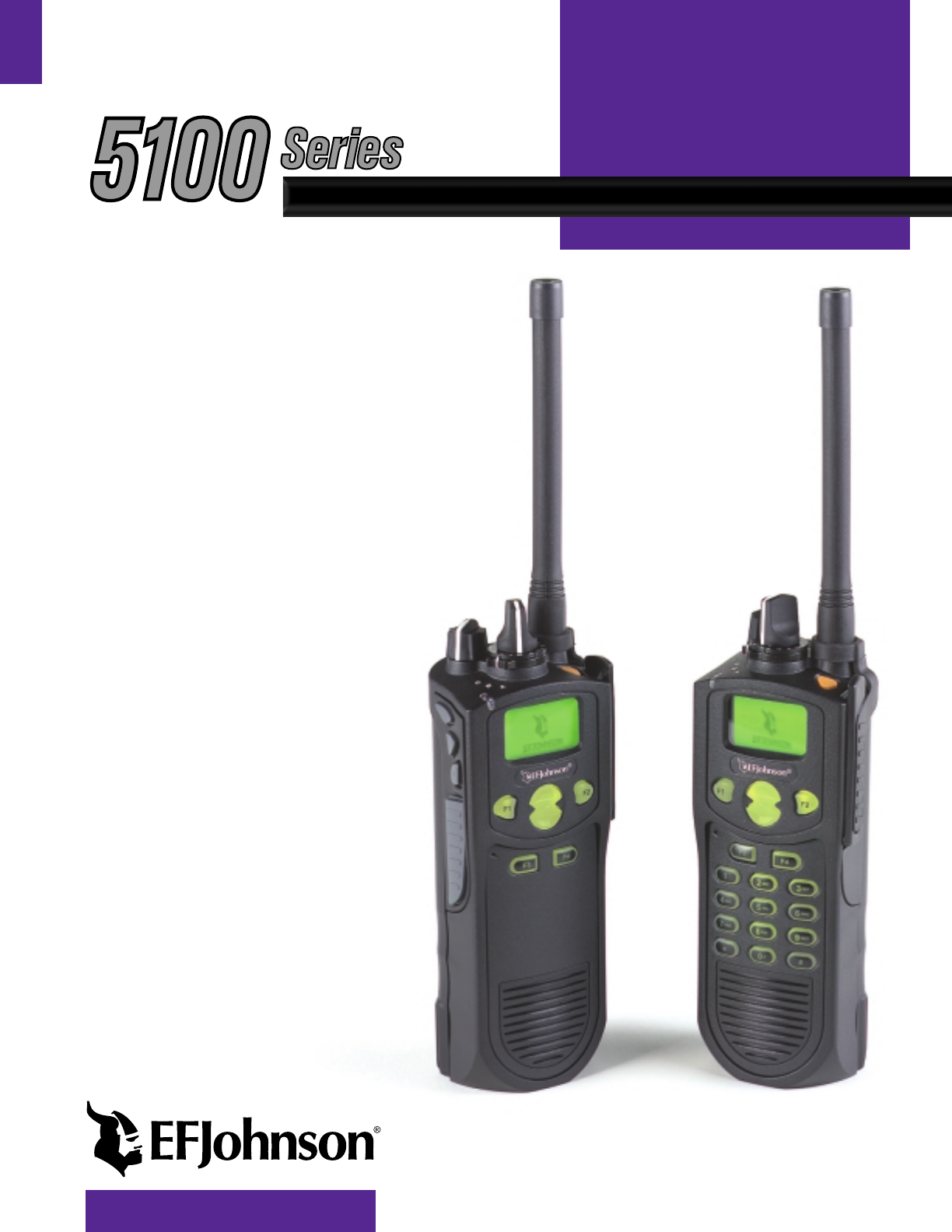
5100 SERIES
PORTABLE RADIO
PROJECT 25 CONVENTIONAL
SMARTNET®/SMARTZONE®
7.2 VDC,
1 and 5 Watts (VHF);
1 and 4 Watts (UHF);
1 and 3 Watts (700/800 MHz)
1 and 2.5 Watts (900 MHz)

3
RF EXPOSURE INFORMATION
RF ENERGY EXPOSURE AWARENESS AND CONTROL
INFORMATION, AND OPERATIONAL INSTRUCTIONS
FOR FCC OCCUPATIONAL USE REQUIREMENTS
BEFORE USING YOUR PORTABLE 2-WAY
RADIO, READ THIS IMPORTANT RF ENERGY
AWARENESS AND CONTROL INFORMATION
AND OPERATIONAL INSTRUCTIONS TO
ENSURE COMPLIANCE WITH THE FCC’S RF
EXPOSURE GUIDELINES.
NOTICE: This radio is intended for use in occupa-
tional/controlled conditions, where users have full
knowledge of their exposure and can exercise control
over their exposure to meet FCC limits. This radio
device is NOT authorized for general population,
consumer, or any other use.
This 2-way radio uses electromagnetic energy in
the radio frequency (RF) spectrum to provide commu-
nications between two or more users over a distance. It
uses radio frequency (RF) energy or radio waves to
send and receive calls. RF energy is one form of elec-
tromagnetic energy. Other forms include, but are not
limited to, electric power, sunlight and x-rays. RF
energy, however, should not be confused with these
other forms of electromagnetic energy, which when
used improperly can cause biological damage. Very
high levels of x-rays, for example, can damage tissues
and genetic material.
Experts in science, engineering, medicine, health
and industry work with organizations to develop stan-
dards for exposure to RF energy. These standards
provide recommended levels of RF exposure for both
workers and the general public. These recommended
RF exposure levels include substantial margins of
protection. All 2-way radios marketed in North
America are designed, manufactured and tested to
ensure they meet government established RF expo-
sure levels. In addition, manufacturers also recom-
mend specific operating instructions to users of 2-way
radios. These instructions are important because they
inform users about RF energy exposure and provide
simple procedures on how to control it. Please refer to
the following websites for more information on what
RF energy exposure is and how to control your expo-
sure to assure compliance with established RF expo-
sure limits.
•http://www.fcc.gov/oet/rfsafety/rf-faqs.html
•http://www.osha.gov/SLTC/
radiofrequencyradiation/index.html
FEDERAL COMMUNICATIONS COMMISSION
REGULATIONS
The FCC rules require manufacturers to comply
with the FCC RF energy exposure limits for portable
2-way radios before they can be marketed in the U.S.
When 2-way radios are used as a consequence of
employment, the FCC requires users to be fully aware
of and able to control their exposure to meet occupa-
tional requirements. Exposure awareness can be facili-
tated by the use of a product label directing users to
specific user awareness information. Your EFJohnson
2-way radio has a RF exposure product label. Also,
your EFJohnson user manual, or product manual, or
separate safety booklet includes information and oper-
ating instructions required to control your RF exposure
and to satisfy compliance requirements.
COMPLIANCE WITH RF EXPOSURE
STANDARDS
Your EFJohnson 2-way radio is designed and tested to
comply with a number of national and international
standards and guidelines (listed below) for human
exposure to radio frequency electromagnetic energy.
This radio complies with the IEEE and ICNIRP expo-
sure limits for occupational/controlled RF exposure
environment at operating duty factors of up to 50%
transmitting and is authorized by the FCC for occupa-
tional use only. In terms of measuring RF energy for
compliance with the FCC exposure guidelines, your
radio radiates measurable RF energy only while it is
transmitting (during talking), not when it is receiving
(listening) or in standby mode. Note: The approved
batteries supplied with this radio are rated for a 5-5-90
duty factor (5% talk-5% listen - 90% standby), even
though this radio complies with the FCC occupational
RF exposure limits and may operate at duty factors of
up to 50% talk.

4
RF EXPOSURE INFORMATION
Your EFJohnson 2-way radio complies with the
following RF energy exposure standards and guide-
lines:
•United States Federal Communications Commis-
sion, Code of Federal Regulations; 47 CFR §§
1.1307, 1.1310, 2.1091 and 2.1093
•American National Standards Institute (ANSI) /
Institute of Electrical and Electronic Engineers
(IEEE) C95. 1-1992
•Institute of Electrical and Electronic Engineers
(IEEE) C95.1-1999 Edition
RF EXPOSURE COMPLIANCE AND CONTROL
GUIDELINES AND OPERATING
INSTRUCTIONS
To control your exposure and ensure compliance
with the occupational/controlled environment expo-
sure limits always adhere to the following procedures.
Guidelines:
•Do not remove the RF Exposure Label from the
device.
•User awareness instructions should accompany
device when transferred to other users.
•Do not use this device if the operational require-
ments described herein are not met.
Operating Instructions:
•Transmit no more than the rated duty factor of 50%
of the time. To transmit (talk), push the Push-To-
Talk (PTT) button. To receive calls, release the PTT
button. Transmitting 50% of the time, or less, is
important because this radio generates measurable
RF energy exposure only when transmitting (in
terms of measuring for standards compliance).
•Hold the radio in a vertical position in front of face
with the microphone (and the other parts of the
radio, including the antenna) at least one inch (2.5
am) away from the nose. Keeping the radio at the
proper distance is important because RF exposures
decrease with distance from the antenna. Antenna
should be kept away from eyes.
•When worn on the body, always place the radio in an
EFJohnson approved clip, holder, holster, case, or
body harness for this product. Using approved
body-worn accessories is important because the use
of EFJohnson or other manufacturer’s non-
approved accessories may result in exposure levels,
which exceed the FCC’s occupational/controlled
environment RF exposure limits.
•Use only EFJohnson approved supplied or replace-
ment antennas, batteries, and accessories. Use of
non-EFJohnson approved antennas, batteries, and
accessories may exceed the FCC RF exposure
guidelines.
•For a list of EFJohnson approved accessories, see
the service manual or marketing accessory lists or
contact the EFJohnson Company
CONTACT INFORMATION
Toll-Free: 800-328-3911
FAX: 507-835-6969
E-Mail: customerservice@efjohnson.com You can
also e-mail a person directly if you know their first
initial/last name (example: jsmith@efjohnson.com).
You may also contact the Customer Service
Department by mail. Please include all information
that may be helpful in solving your problem. The
mailing address is as follows:
E.F. Johnson Company
Customer Service Department
299 Johnson Avenue
P.O. Box 1249
Waseca, MN 56093-0514

5
RF EXPOSURE INFORMATION
ELECTROMAGNETIC INTERFERENCE
This device complies with Part 15 of the FCC
rules. Operation is subject to the condition that this
device does not cause harmful interference. In addi-
tion, changes or modification to this equipment not
expressly approved by the EFJohnson Company could
void the user’s authority to operate this equipment
(FCC Rules, 47CFR Part 15.19).
USAGE COMPATIBILITY
DO NOT operate it in areas that are sensitive to
RF energy such as aircraft, hospitals, blasting sites,
and fuel storage sites. Areas with potentially flam-
mable atmospheres are usually, but not always, clearly
posted. These may include gas stations, fuel and chem-
ical storage and transfer stations, below deck on boats,
and areas where the air contains flammable chemicals
or particles such as grain dust or metal powders.
BATTERY DISPOSAL
Dispose of the nickel metal-hydride (NiMH) or
nickel-cadmium (NiCd) battery used by this radio in
accordance with local regulations. DO NOT dispose of it
in fire because it can explode. Also, do not short the
terminals because it may become very hot.

51xx SERIES PORTABLE
OPERATING MANUAL
VHF/UHF/700/800/900 MHz
PROJECT 25 (DIGITAL) AND ANALOG
SMARTNET®/SmartZone®
Copyright© 2004, 2005 by the EFJohnson Company
The EFJohnson Company, which was founded in 1923, provides wireless communication
systems solutions for public safety, government, and commercial customers. The company
designs, manufactures, and markets conventional and trunked radio systems, mobile and
portable subscriber radios, repeaters, and Project 25 digital radio products. EFJohnson is a
wholly owned subsidiary of EFJ, Inc.
Viking Head/EFJohnson logo, PCConfigure™, and Call Guard® are trademarks of the
EFJohnson Company. SMARTNET®, SmartZone®, SecureNet™, Call Alert™, Enhanced Pri-
vate Conversation™, and Private Conversation II™ are trademarks of Motorola, Inc. All other
company and/or product names used in this manual are trademarks and/or registered trade-
marks of their respective manufacturer. The IMBE™ voice coding technology embodied in
this product is protected by intellectual property rights including patent rights of Digital Voice
Systems, Inc.
LAND MOBILE PRODUCT WARRANTY - The manufacturer’s warranty statement for this
product is available from your product supplier or from EFJohnson Company, 299 Johnson
Avenue, Box 1249, Waseca, MN 56093-0514. Phone (507) 835-6222.
Information in this manual is subject to change without notice.
5100 Flash Version 1.11.0/PCConfigure Version 1.21

7
TABLE OF CONTENTS
TABLE OF CONTENTS
RF EXPOSURE INFORMATION
1 FEATURES
1.1 General Features . . . . . . . . . . . . . . . . . . . . . . . . . . .9
1.2 Conventional Features . . . . . . . . . . . . . . . . . . . . . . .9
1.3 SMARTNET/SmartZone Features . . . . . . . . . . . .10
1.4 Project 25 Trunked Features . . . . . . . . . . . . . . . . .10
2 CONTROLS AND DISPLAY
2.1 Front Panel Controls . . . . . . . . . . . . . . . . . . . . . . .11
2.2 Top Panel Controls . . . . . . . . . . . . . . . . . . . . . . . .11
2.3 Side Controls . . . . . . . . . . . . . . . . . . . . . . . . . . . . .12
2.4 Display. . . . . . . . . . . . . . . . . . . . . . . . . . . . . . . . . .12
3 GENERAL OPERATION
3.1 Turning Power On and Setting Volume . . . . . . . .13
Power Up . . . . . . . . . . . . . . . . . . . . . . . . . . . . . 13
Standard and Soft Power Down . . . . . . . . . . . . 13
Setting Volume Level. . . . . . . . . . . . . . . . . . . . 13
3.2 Power-Up Password. . . . . . . . . . . . . . . . . . . . . . . .13
3.3 Zone and Channel Select . . . . . . . . . . . . . . . . . . . .14
3.4 Low Battery Indication . . . . . . . . . . . . . . . . . . . . .15
3.5 Backlight . . . . . . . . . . . . . . . . . . . . . . . . . . . . . . . .16
3.6 Keypad Lock . . . . . . . . . . . . . . . . . . . . . . . . . . . . .16
3.7 Setting Squelch . . . . . . . . . . . . . . . . . . . . . . . . . . .16
3.8 Transceiver Operating Modes . . . . . . . . . . . . . . . .16
General . . . . . . . . . . . . . . . . . . . . . . . . . . . . . . . 16
Conventional Mode. . . . . . . . . . . . . . . . . . . . . . 16
SMARTNET/SmartZone Mode . . . . . . . . . . . . 17
P25 Trunked Mode . . . . . . . . . . . . . . . . . . . . . . 17
Systems, Channels, and Zones . . . . . . . . . . . . . 17
4 RADIO-WIDE FEATURES
4.1 Option Switches. . . . . . . . . . . . . . . . . . . . . . . . . . .18
4.2 Menu Mode . . . . . . . . . . . . . . . . . . . . . . . . . . . . . .18
4.3 Time-Out Timer. . . . . . . . . . . . . . . . . . . . . . . . . . .19
4.4 Home Zone/Channel Select. . . . . . . . . . . . . . . . . .19
4.5 Power Output Select . . . . . . . . . . . . . . . . . . . . . . .19
4.6 Alert Tone Select . . . . . . . . . . . . . . . . . . . . . . . . . .19
4.7 Surveillance Mode. . . . . . . . . . . . . . . . . . . . . . . . .21
4.8 Scanning . . . . . . . . . . . . . . . . . . . . . . . . . . . . . . . .21
Introduction. . . . . . . . . . . . . . . . . . . . . . . . . . . . 21
Standard Scanning . . . . . . . . . . . . . . . . . . . . . . 21
Radio Wide Scanning . . . . . . . . . . . . . . . . . . . 21
Scan Hold Time . . . . . . . . . . . . . . . . . . . . . . . . 22
Transmitting in the Scan Mode . . . . . . . . . . . . . 22
Nuisance Channel Add/Delete. . . . . . . . . . . . . . 22
4.9 Scan Lists . . . . . . . . . . . . . . . . . . . . . . . . . . . . . . . 22
Standard Mode Scan Lists . . . . . . . . . . . . . . . . . 22
Radio Wide Scan List . . . . . . . . . . . . . . . . . . . . 22
Determining Which Channels are in Scan List . 23
Selecting a Scan List . . . . . . . . . . . . . . . . . . . . . 23
Editing a Scan List. . . . . . . . . . . . . . . . . . . . . . . 23
5 CONVENTIONAL MODE FEATURES
5.1 Introduction . . . . . . . . . . . . . . . . . . . . . . . . . . . . . 24
5.2 Monitoring Before Transmitting . . . . . . . . . . . . . 24
5.3 Monitor Mode. . . . . . . . . . . . . . . . . . . . . . . . . . . . 24
5.4 Busy Channel Lockout . . . . . . . . . . . . . . . . . . . . . 25
5.5 Call Guard Squelch. . . . . . . . . . . . . . . . . . . . . . . . 25
Introduction . . . . . . . . . . . . . . . . . . . . . . . . . . . . 25
Call Guard Squelch Enable/Disable . . . . . . . . . 25
Tone Call Guard Squelch. . . . . . . . . . . . . . . . . . 25
Digital Call Guard Squelch . . . . . . . . . . . . . . . . 26
Selective Squelch Code Select. . . . . . . . . . . . . . 26
5.6 Penalty Timer . . . . . . . . . . . . . . . . . . . . . . . . . . . . 26
5.7 Conversation Timer . . . . . . . . . . . . . . . . . . . . . . . 27
5.8 Repeater Talk-Around . . . . . . . . . . . . . . . . . . . . . 27
5.9 Displaying Transmit/Receive Frequency . . . . . . . 27
5.10 Emergency Alarm and Call . . . . . . . . . . . . . . . . . 27
Introduction . . . . . . . . . . . . . . . . . . . . . . . . . . . . 27
Emergency Alarms . . . . . . . . . . . . . . . . . . . . . . 27
Emergency Calls . . . . . . . . . . . . . . . . . . . . . . . . 28
5.11 Conventional Mode Scanning . . . . . . . . . . . . . . . 28
General. . . . . . . . . . . . . . . . . . . . . . . . . . . . . . . . 28
Transmitting in Scan Mode . . . . . . . . . . . . . . . . 28
Priority Channel Sampling . . . . . . . . . . . . . . . . 28
Changing the Priority Channel . . . . . . . . . . . . . 29
5.12 Standard Conventional Calls . . . . . . . . . . . . . . . . 29
5.13 DTMF/ANI Signaling. . . . . . . . . . . . . . . . . . . . . . 30
5.14 Clone Mode . . . . . . . . . . . . . . . . . . . . . . . . . . . . . 30
5.15 Single Tone Encoder . . . . . . . . . . . . . . . . . . . . . . 31
5.16 Project 25 Mode Features. . . . . . . . . . . . . . . . . . . 31
Unit ID Code . . . . . . . . . . . . . . . . . . . . . . . . . . . 31
Group ID Code . . . . . . . . . . . . . . . . . . . . . . . . . 31
Network Access Code . . . . . . . . . . . . . . . . . . . . 31
P25 Group Calls. . . . . . . . . . . . . . . . . . . . . . . . . 31
P25 Unit Calls . . . . . . . . . . . . . . . . . . . . . . . . . . 31
Call Alert . . . . . . . . . . . . . . . . . . . . . . . . . . . . . . 32
Messaging . . . . . . . . . . . . . . . . . . . . . . . . . . . . . 33
Status Messaging . . . . . . . . . . . . . . . . . . . . . . . . 33
5.17 Keypad Programming. . . . . . . . . . . . . . . . . . . . . . 33
Introduction . . . . . . . . . . . . . . . . . . . . . . . . . . . . 33
Menu Description . . . . . . . . . . . . . . . . . . . . . . . 34

TABLE OF CONTENTS
8
Zone Password . . . . . . . . . . . . . . . . . . . . . . . . . 34
Zone Change Parameter . . . . . . . . . . . . . . . . . . 34
Channel Change Parameter. . . . . . . . . . . . . . . . 34
System Parameters . . . . . . . . . . . . . . . . . . . . . . 34
Channel Parameters . . . . . . . . . . . . . . . . . . . . . 35
6 SMARTNET/SMARTZONE/P25
TRUNKED FEATURES
6.1 Introduction . . . . . . . . . . . . . . . . . . . . . . . . . . . . . .36
6.2 Analog and Digital Operation . . . . . . . . . . . . . . . .36
6.3 Viewing Unit ID . . . . . . . . . . . . . . . . . . . . . . . . . .36
6.4 Standard Group Calls. . . . . . . . . . . . . . . . . . . . . . .36
Introduction. . . . . . . . . . . . . . . . . . . . . . . . . . . . 36
Placing a Standard Group Call . . . . . . . . . . . . . 36
Receiving a Standard Group Call . . . . . . . . . . . 37
6.5 Private (Unit-To-Unit) Calls . . . . . . . . . . . . . . . . .37
General . . . . . . . . . . . . . . . . . . . . . . . . . . . . . . . 37
Placing an Enhanced Private Conversation Call 37
Placing a Standard Private Conversation Call . 38
Receiving a Private Call (All Types) . . . . . . . . 39
6.6 Telephone Calls . . . . . . . . . . . . . . . . . . . . . . . . . . .39
General . . . . . . . . . . . . . . . . . . . . . . . . . . . . . . . 39
Placing a Telephone Call . . . . . . . . . . . . . . . . . 39
Answering a Telephone Call. . . . . . . . . . . . . . . 40
6.7 Call Alert . . . . . . . . . . . . . . . . . . . . . . . . . . . . . . .40
General . . . . . . . . . . . . . . . . . . . . . . . . . . . . . . . 40
Answering a Page . . . . . . . . . . . . . . . . . . . . . . . 40
Initiating a Page . . . . . . . . . . . . . . . . . . . . . . . . 41
6.8 Messaging. . . . . . . . . . . . . . . . . . . . . . . . . . . . . . . 41
6.9 Sending Status Conditions . . . . . . . . . . . . . . . . . . 41
6.10 Emergency Alarm and Call . . . . . . . . . . . . . . . . . 41
Introduction . . . . . . . . . . . . . . . . . . . . . . . . . . . . 41
Emergency Alarms . . . . . . . . . . . . . . . . . . . . . . 42
Emergency Calls . . . . . . . . . . . . . . . . . . . . . . . . 42
6.11 Failsoft Operation. . . . . . . . . . . . . . . . . . . . . . . . . 42
6.12 SMARTNET/Smartzone/P25 Trunked Scanning
Features. . . . . . . . . . . . . . . . . . . . . . . . . . . . . . . . . 42
General. . . . . . . . . . . . . . . . . . . . . . . . . . . . . . . . 42
Priority Talk Group Sampling . . . . . . . . . . . . . . 43
6.13 Dynamic Regrouping . . . . . . . . . . . . . . . . . . . . . . 43
6.14 SmartZone and P25 Trunked Unique Features. . . 43
Introduction . . . . . . . . . . . . . . . . . . . . . . . . . . . . 43
Busy Override . . . . . . . . . . . . . . . . . . . . . . . . . . 43
Site Trunking . . . . . . . . . . . . . . . . . . . . . . . . . . . 44
Determining Current Site and Searching For
New Site . . . . . . . . . . . . . . . . . . . . . . . . . . . . 44
Locking/Unlocking a Site . . . . . . . . . . . . . . . . . 44
7 MISCELLANEOUS
7.1 Supervisory Tones . . . . . . . . . . . . . . . . . . . . . . . . 44
7.2 System Operator Programming . . . . . . . . . . . . . . 45
7.3 Speaking Into Microphone . . . . . . . . . . . . . . . . . . 45
7.4 Operation At Extended Range . . . . . . . . . . . . . . . 45
7.5 Licensing . . . . . . . . . . . . . . . . . . . . . . . . . . . . . . . 45
7.6 Transceiver Service . . . . . . . . . . . . . . . . . . . . . . . 45
9
FEATURES
SECTION 1 FEATURES
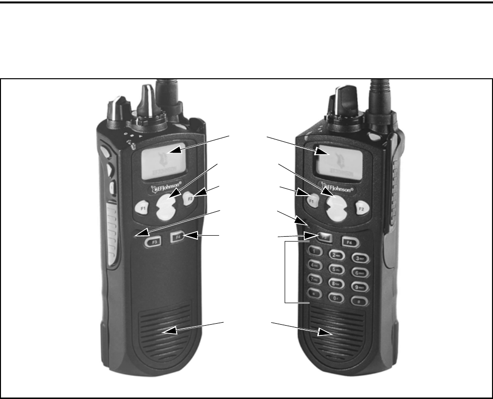
Figure 1-1 Front Panel Controls
Speaker
Display
DTMF Keypad
Option Keys
Microphone
DTMF Keypad Model
Limited Keypad Model
Up/Down Sw
Menu/Option
Keys
F1 = Exit
In Various Modes:
F2 = Select/Menu
Enable
NOTE: The availability of many of the following
features is controlled by factory coding of your trans-
ceiver, installed options, and field programming. Refer
to Section 9 for more information.
1.1 GENERAL FEATURES
•The following operating modes are programmable:
– Conventional analog
– Conventional Project 25 (digital)
– Trunked Project 25 (digital)
– SMARTNET™/SmartZone® trunked (analog
or digital)
•Up to 16 zones with 16 channels each (256 channels
total) are standard. Up to 32 zones and 512 channels
total are optional.
•Large graphic display with backlight
•Up to 9 (limited keypad) or 21 (DTMF keypad)
programmable option switches
•Menu mode
•Standard and radio-wide scan modes
•Time-out timer
•User selectable high and low power output
•Keypad lock to prevent accidental key presses
•Operates on both wide and narrow band channels
•Power-up password to prevent unauthorized use
•Adjustable tone volume (with Flash code 1.9.0 or
later only)
•Soft power down (with Flash code 1.9.0 or later
only)
1.2 CONVENTIONAL FEATURES
•Up to 512 channels or talk groups programmable
•Repeater talk-around
•Carrier or Call Guard® controlled squelch on analog
channels, NAC and talk group IDs on P25 channels.

FEATURES
10
•Normal/selective squelch selectable by option
switch or menu
•Monitor mode selectable by option switch or menu
•Penalty and conversation timers
•Dual priority channel sampling when scanning
(analog channels only)
•Busy channel lockout (transmit disable on busy)
•Unit calls on P25 channels
•Cloning capability
•Emergency alarms and calls to alert a dispatcher of
an emergency condition (analog emergency avail-
able only with Flash code 1.8.0 or later).
•Single tone encoder controllable by user on analog
channels
•ANI (Automatic Number Identification) on analog
channels
•Call Alert™ on P25 channels (send and receive
pages) with Flash code 1.8.0 or later.
•Predefined messages (up to 16) can be sent to a
dispatcher (P25 mode with Flash code 1.8.0 or later
only)
•Predefined status conditions (up to 8) can be sent to
a dispatcher (P25 mode with Flash code 1.8.0 or
later only)
•SecureNet™ DES/DES-XL voice encryption avail-
able on analog channels, DES-OFB and AES on P25
channels (see Section 8.1.4 for more information).
•OTAR (Over-The-Air-Rekeying) compatible (P25
channels with Flash code 1.5.0 or later).
•Keypad programming with password access
(Federal Government users only)
1.3 SMARTNET/SMARTZONE FEATURES
•Up to 512 talk groups programmable (channels
select talk groups)
•Group, Enhanced Private Conversation™, standard
Private Conversation, and Telephone* Calls
•Emergency alarms to alert a dispatcher of
emergency conditions
•Emergency calls for high priority system access
•Failsoft operation on a predefined conventional
channel if trunked system fails
•Priority group calls detected while listening to other
group calls when scanning
•Call Alert™ (send and receive pages)
•Predefined messages (up to 16) can be sent to a
dispatcher
•Predefined status conditions (up to 8) can be sent to
a dispatcher
•Dynamic regrouping (dispatcher can automatically
gather users on a channel to receive a message)
•Roaming (SmartZone only)
•SecureNet™ DES secure communication available
on analog channels (SmartZone requires Flash code
1.7.0 or later). DES-OFB and AES on digital
channels (AES encryption available only with Flash
code 1.8.0 or later).
1.4 PROJECT 25 TRUNKED FEATURES
•Up to 512 talk groups programmable (channels
select talk groups)
•Group and Unit Calls
•Emergency alarms to alert a dispatcher of
emergency conditions
•Emergency calls for high priority system access
•Failsoft operation on a predefined conventional
channel if trunked system fails
•Priority group calls detected while listening to other
group calls when scanning
•Call Alert™ (send and receive pages)
•Predefined status conditions (up to 8) can be sent to
a dispatcher
•Dynamic regrouping (dispatcher can automatically
gather users on a channel to receive a message)
•Roaming
•SecureNet™ DES-OFB and AES secure communi-
cation available (AES encryption available only
with Flash code 1.8.0 or later)
* Telephone calling is currently not available.
11
CONTROLS AND DISPLAY
SECTION 2 CONTROLS AND DISPLAY
2.1 FRONT PANEL CONTROLS
NOTE: The location of these controls is shown in
Figure 1-1.
Microphone - The microphone is located behind the
small opening shown in Figure 1-1. For best results,
hold the transceiver 2-3 inches from you mouth and
speak at a normal conversational level. Do not shout
since it distorts your voice and does not increase range.
Display - This is a graphical LCD (Liquid Crystal
Display). The display backlight can be programmed to
turn on when any key is pressed or when the Backlight
option switch is pressed or menu parameter selected
(see Section 3.5).
Up/Down Switch - Selects zones when multiple zones
are programmed (see Section 3.3). Pressing the upper
part of the switch selects the next higher number and
pressing the lower part selects the next lower number.
This control also provides up/down select in the menu
mode and in other modes when up/down select is
required.
F1 - In menu mode (see Section 4.2), functions as a
step back and exit switch. If menu mode is not used, it
is a programmable option switch.
F2 - Selects the menu mode when it is enabled by
programming. Also functions as an Enter or Select
switch in the menu and other modes. If menu mode is
not used, it is a programmable option switch.
F3, F4 - Programmable option switches.
DTMF Keypad - The full keypad DTMF models
include the 12 keys required to dial telephone and unit
ID numbers.
Speaker - The transceiver speaker is located near the
bottom of the front panel. When a speaker/microphone
is used, it is automatically detected when the Opt Sel 1
line of the accessory connector is pulled low. The logic
then automatically disables the internal speaker.
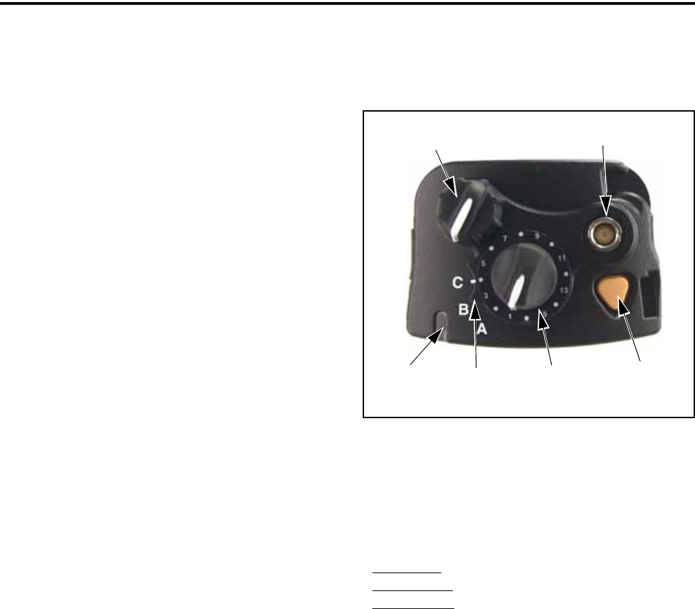
Figure 2-1 Top Panel Controls
2.2 TOP PANEL CONTROLS
Multi-Function Indicator - Indicates the following
conditions:
Steady Red - Transmitter keyed.
Flashing Red - Low battery in receive mode.
Steady Green - Carrier detected in receive mode.
NOTE: This indicator is disabled if the Surveillance
mode is programmed (see Section 4.7).
On-Off/Volume - Turning the knob clockwise turns
power on and sets the volume level. Turning it coun-
terclockwise to the detent turns power off. The
minimum volume level can be set by programming.
Channel Switch - This 16-position switch selects up
to 16 channels in the current zone. Additional zones
can be programmed to allow up to 512 channels to be
selected by this switch.
Rotary Option Switch - This is a three-position
switch that can be programmed to control various
options. The “A” position is “off” and the “B” and “C”
positions are “on” (see Section 4.1). When this switch
Emergency
(Option)
Power On-Off/
Volume Adj
Channel
Switch
Antenna
Connector
Option
Switch Switch
Multi-Function
Indicator
CONTROLS AND DISPLAY
12
is programmed to select zones, “A” selects Zone 1,
“B” Zone 2, and “C” Zone 3 if applicable (available
only with Flash code 1.7.0 or later).
Antenna Connector - Connection point for the
antenna. Make sure the antenna is tight before using
the radio.
Emergency Switch - This switch or some other option
switch can be programmed as an Emergency switch to
alert a dispatcher of an emergency condition. Refer to
Sections 5.10 and 6.10 for more information. This
switch can also be programmed for other functions.
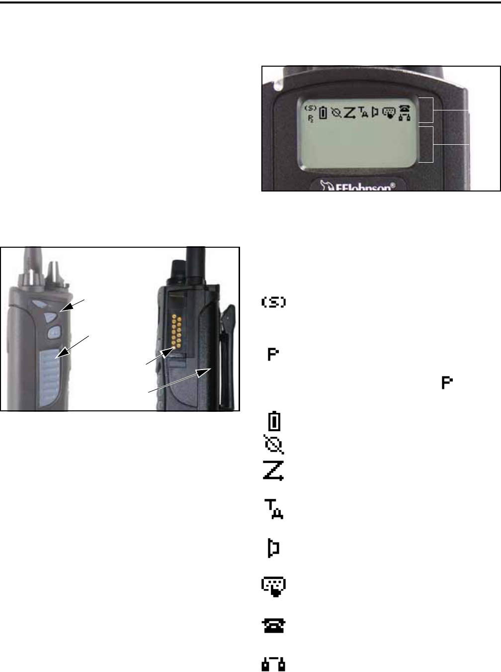
2.3 SIDE CONTROLS
Figure 2-2 Side Controls and Jacks
PTT (Push-To-Talk) Switch - This switch is pressed
to turn the transmitter on to transmit a message. It is
then released to listen. Transmitting is indicated when
the top panel indicator is constant red.
Option Switches 1, 2, and 3 - Each of these switches
can be programmed to control a specific function (see
Section 4.1). In addition, they can also be programmed
for soft power down (see Section 3.1.2).
Battery - To remove the battery, press the release
button on the bottom and pivot the bottom of the
battery outward.
Accessory Connector - Connection point for optional
accessories such as a speaker/microphone or earphone.
It is also used for connecting the computer when
programming the transceiver.
2.4 DISPLAY
Figure 2-3 Graphical Display
The front panel display is shown above. Icons are
typically shown in the upper part of the display and
text messages in the lower part. The default icons are
as follows:
- When the scan or the scan list edit mode is
enabled, indicates that the displayed channel is in the
scan list and scanned normally (see Section 4.8).
- When the scan or the scan list edit mode is
enabled, indicates that the displayed channel is a
priority channel. If dual priority is used, indicates
that it is a second priority channel.
- Low battery indication (see Section 3.4).
- Voice encryption is enabled (see Section 8.1).
- Standard or radio wide scanning is enabled
(see Section 4.8).
- Repeater talk-around is enabled (see
Section 5.8).
- Monitor mode is enabled by the Monitor
option switch or menu parameter (see Section 5.3).
- Keypad programming or another mode is
enabled which allows the user to edit radio parameters.
- A SMARTNET/SmartZone interconnect*
(telephone) call is in progress (see Section 6.6).
- A Project 25 or SMARTNET/SmartZone
private (unit-to-unit) call is in progress.
Option Switches
PTT Switch
Battery Pack
Accessory
Connector
1
2
3
Icon
Area
Text
Area
2
* Telephone calling is currently not available.

13
GENERAL OPERATION
SECTION 3 GENERAL OPERATION
3.1 TURNING POWER ON AND SETTING
VOLUME
3.1.1 POWER UP
Power is turned on and off by the top panel On-
Off/Volume switch. When power is initially turned on,
the following events occur:
•The software version number is displayed.
•A self test is performed.
•The currently selected zone is displayed.
•If a conventional P25 channel is selected, the
Individual ID of the radio is displayed.
•If a SMARTNET/SmartZone or P25 Trunked
channel is selected, the Unit ID of the radio is
displayed.
•A tone sounds (if tones are enabled)
•The selected channel alias is displayed continuously
when power-up is complete.
Programming determines if the transceiver
powers up on the last selected zone or the pre-
programmed home zone. Refer to Section 3.3 for
information on the channel that is selected. The
minimum volume level may be set by programming.
This can prevent missed messages resulting from inad-
vertently turning the volume to an inaudible level.
3.1.2 STANDARD AND SOFT POWER DOWN
To turn power off, rotate the On-Off/Volume
control counterclockwise until a click occurs. Power
may remain on for an instant after turn-off occurs.
A soft power down feature* can be programmed
to prevent radio power from being turned off by acci-
dentally turning the on-off/volume control. Any side
button can be programmed for this function (in addi-
tion to the normal function). Then for power to turn
off, this button must be pressed during or after power
is turned off in the normal manner using the knob.
When this feature is programmed, turning the on-off/
volume knob to off has no affect.
3.1.3 SETTING VOLUME LEVEL
The volume level is adjusted by the top panel
volume control knob or by option buttons programmed
for the Up/Down volume function**. When the
buttons are used, the volume control function of the
knob is disabled (it is still used to switch power).
Volume buttons may be used instead of the knob, for
example, if accidental turning of the volume knob
occurs.
When the volume control buttons are used, the
number of steps (ticks) the volume changes from
minimum to maximum is programmable for 1-50. For
example, if “20” is programmed, there are 20 adjust-
ment steps from minimum to maximum volume. Only
one volume control button can be programmed if
desired and wrap-around then occurs after the
maximum or minimum level is selected.
The relative volume level can be determined by
the position of the index on the volume knob or by a
reference tone as follows:
•If a key press tone is enabled, a short tone sounds
when a key is pressed.
•If a conventional channel is selected and the
Monitor option switch or menu parameter is
programmed, pressing that switch unsquelches the
receiver and either voice or background noise is
heard (see Section 5.3). If a SMARTNET/Smart-
Zone or P25 Trunked channel is selected, the
receiver cannot be manually unsquelched.
3.2 POWER-UP PASSWORD
The power-up password feature prevents unau-
thorized use of the transceiver by locking the keypad
on power up until the proper password is entered. This
feature is enabled or disabled by programming.
When it is enabled, “ENTER PSWD” is briefly
displayed when power is turned on. The eight-digit
numeric password must be then be entered as follows.
In addition, since the logic resets each time program-
* This feature requires 51xx operating (Flash) software
1.9.0 or later and PCConfigure 1.20 or later. ** This feature requires 51xx operating (Flash) soft-
ware 1.11.0 or later and PCConfigure 1.21 or later.

GENERAL OPERATION
14
ming data is read or written, it must be entered after
performing those functions. If an incorrect password is
entered, “INCORRECT” is displayed and it must be
re-entered.
DTMF Keypad Models - Enter the password using
the 1-8 keys and then press the Enter (F2) key when
finished. If a mistake is made, the last digit can be
erased by pressing the F1 (Clear) key.
Limited Keypad Models - Select the proper number
for each position by pressing the Up/Down switch.
When the proper number for a position is displayed,
select it and move on to the next position by pressing
the F2 (Enter) key.
This password can be changed only by the
programmer (see Section 4 of the 5100 Service
Manual). It cannot be changed by the user. If it is lost,
all programming must be erased to make the trans-
ceiver operational again. This is done using the
“EEPROM Erase” function of the PCTune program
(see Section 6.3.3 of the 5100 Service Manual). This
password is displayed by the programmer when data is
read. However, data cannot be read (or written) when
the transceiver is locked, so the lost password cannot
be determined using the programmer.
3.3 ZONE AND CHANNEL SELECT
The selected zone and channel are selected and
displayed as follows. For more information on zones
and channels, refer to Section 3.8.5.
Zone Select
The front panel Up/Down switch changes and
displays the current zone. When not in special modes
such as the menu mode, pressing either the top or
bottom part of this switch once displays the alias of the
current zone. Then quickly pressing it again changes
the selected zone up or down. The rotary A/B/C switch
on the top panel can also be programmed for zone
select (with Flash code 1.7.0 or later). The “A” posi-
tion then selects Zone 1, “B” Zone 2, and “C” Zone 3
(if applicable).
After the highest programmed zone is displayed,
wrap-around to the lowest programmed zone occurs
and vice versa. The selected zone is also displayed
briefly on power up. If the selected zone alias needs to
be displayed continuously, it must be programmed as
part of the channel alias.
Channel Select
Channels are selected by the rotary 16-position
switch on the top panel. The alias (identification) for
the selected channel/group is displayed continuously
during normal operation.
When an unprogrammed channel is selected,
“UNPROGRAMD” is displayed and a tone sounds (if
tones are enabled). When conventional channels are
selected and the Display Information option key or
menu parameter is programmed, either the channel
frequency or alias can be displayed (see Section 5.9).
The channel selector knob can also be disabled by
programming. Channels must then be directly selected
as described next (if applicable). This knob may be
disabled when direct selection is used to prevent
confusion because it then may not correctly indicate
the selected channel.
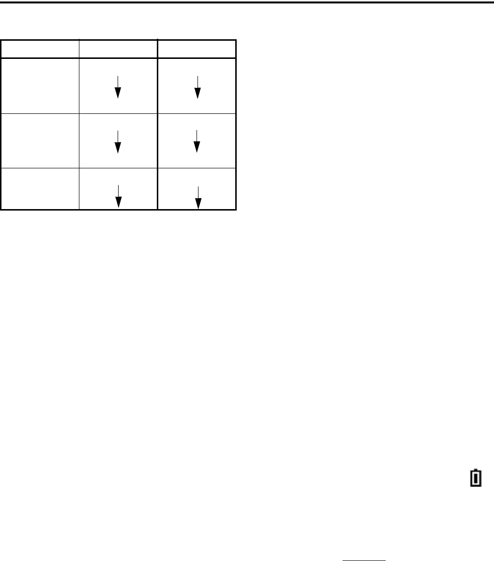
Direct Zone/Channel Selection*
The direct Channel Select feature is available if
the Channel Select option switch or menu parameter is
programmed. This feature allows channels to be
directly selected using the DTMF keypad numeric
keys (DTMF models only) or Up/Down switch (all
models).
For direct selection purposes, channels are
numbered sequentially starting with the lowest zone.
Each zone can be programmed with up to 16 channels,
so Zone 1 channels are numbered 1-16, Zone 2 chan-
nels 17-32, and so on as shown below. For example,
Zone 1/Channel 16 is selected by Channel 16, and
Zone 2/Channel 16 is selected by Channel 32.
Proceed as follows to select channels using this
mode:
1. Enable the direct Channel Select mode by pressing
the Channel Select option switch or selecting the
“Chan Selct” menu parameter. The alias and
sequential number of the current channel are alter-
nately displayed.
* This feature requires 51xx operating (Flash) software
1.5.0 or later and PCConfigure 1.17 or later.
GENERAL OPERATION
15
2. Select the desired channel using the Up/Down keys
or directly enter it using the 0-9 keys (if available).
If using the 0-9 keys, the radio attempts to display
the entered number after the 3rd digit is entered or
approximately 2 seconds after the last key is
pressed.
3. To exit the this mode and select the entered channel,
press the Channel Select switch again or the F2 key.
To exit without changing the channel, press the F1
key. This mode is also exited automatically without
changing the channel after approximately 1 minute
of no activity.
NOTE: The Channel Select function should probably
not be assigned to a number key because pressing that
key to select a channel then exits the select mode.
Other features of this mode are as follows:
•When using the Up/Down keys, wrap-around to the
lowest zone/channel occurs after the last channel in
the highest programmed zone is displayed and vice
versa. For example, if Zone 1/Channel 5 is the
highest programmed channel, wraparound occurs
after Zone 1/Channel 16 is displayed.
•When an unprogrammed channel is displayed, the
sequential channel number and “Unprogramd” are
alternately displayed.
•If an invalid channel number is entered using the
0-9 keys, or the F2 or Channel Select open switch is
pressed with “Unprogrammed” displayed, an error
tones sounds, “Invalid” is briefly displayed, and the
displayed channel does not change.
•The rotary Channel Select switch may not correctly
indicate the selected channel after direct channel
selection is used. However, if this switch is enabled
by programming and rotated, it selects the channel it
is indicating. For example, if the switch index is
pointing to channel 3 and channel 15 of the current
zone is being displayed, rotating it to channel 4
selects channel 4 of the current zone.
•If the rotary Channel Select switch is enabled, the
radio always powers up on the channel it is
selecting.
If it is disabled, the radio can be programmed to
power-up on the last selected or home channel
number of the last selected or home zone*. With the
“Last Zone”/“Home Channel” configuration, the
programmed home channel number of the last active
zone is selected. If it is not programmed, “Unpro-
grammd” is displayed. With earlier models, the last
selected channel is displayed when powering up on
the last selected zone, and channel 1 is displayed
when powering up on the home zone.
3.4 LOW BATTERY INDICATION
NOTE: If the transceiver contains encryption (hard-
ware) keys, be sure to reattach a battery within
approximately one minute to prevent the loss of these
keys.
A low-battery condition is indicated by the
icon in the display. The battery should be recharged or
replaced as soon after this indication appears. Once
this indication appears, it stays on until power is
cycled.
The following additional low battery indications
and conditions may be enabled by programming:
•A chirp sounds once a minute in the standby and
transmit modes.
•A chirp sounds each time the PTT switch is pressed.
•The top panel LED indicator flashes red every 30
seconds in the receive mode.
•Low power is selected when transmitting.
Zone Ch. Seq. Ch. No.
111
16 16
2117
16 32
3133
* This feature requires 51xx operating (Flash) software
1.9.0 or later and PCConfigure 1.20 or later.

GENERAL OPERATION
16
As indicated in the preceding “Note”, the trans-
ceiver must be connected to a constant power source to
preserve the encryption (hardware) keys in memory. To
allow the battery to be changed without losing these
keys, storage capacitors maintain the supply voltage to
memory for approximately 1 minute without a battery
attached. Therefore, when changing the battery of a
transceiver that has these keys stored, be sure to reat-
tach a battery within that time. Refer to Section 8.1.6
for more information on encryption keys.
There is a battery saver feature that can be
enabled by programming. This feature functions on
trunked channels and Flash code 1.7.0 or later only,
and it causes low transmit power to be selected when
the receive signal strength (RSSI) indicates that the
site is nearby.
3.5 BACKLIGHT
The backlight for the display and option keys can
be programmed to automatically turn on when any key
is pressed. It then automatically turns off after a
programmed delay of 0-7.5 seconds so that battery
drain is minimized. If the Backlight option switch or
menu parameter is programmed, the user can manually
turn the backlight on and off (it then stays on). If the
Surveillance mode is programmed, the backlight is
disabled (see Section 4.7).
3.6 KEYPAD LOCK
The Keypad Lock feature temporarily disables
the front panel keys to prevent accidental key presses.
This feature is available if the Keypad Lock option
switch is programmed.
To lock the keypad, simply press the Keypad
Lock option switch. Then to unlock the keypad again,
press and hold this switch until a tone sounds or for
approximately 1 second.
With DTMF models, the DTMF keys can be
totally disabled by programming. In addition, they can
be selectively enabled or disabled on conventional
analog channels.
3.7 SETTING SQUELCH
This transceiver does not have a squelch control.
The squelch level is preset during alignment. If the
keypad programming feature is available (see Section
5.17), the squelch level can be changed by the user on
each conventional analog channel.
3.8 TRANSCEIVER OPERATING MODES
3.8.1 GENERAL
Each selectable channel can be programmed for
the conventional (analog or Project 25 digital),
SMARTNET/SmartZone, or Project 25 digital trunked
operating mode. For example, Zone 1/Channel 1 could
be a conventional channel, Zone 1/Channel 2 a
SMARTNET channel, and so on. More information on
these modes follows.
3.8.2 CONVENTIONAL MODE
This is a non-trunked operating mode which
accesses independent radio channels. There is no auto-
matic access to several channels. Selecting a conven-
tional channel selects a transmit and receive frequency
and other channel parameters such as squelch control
coding.
Conventional channels can be either standard
(analog) or Project 25 (digital). With digital operation,
the DSP (Digital Signal Processor) converts the audio
signal to digital data which is sent over the air as
complex tones. Another difference is that analog chan-
nels use Call Guard (CTCSS/DCS) squelch control
and Project 25 channels use a NAC (Network Access
Code) and talk group ID codes.
With Project 25 operation, a NAC is transmitted
and it must match the NAC programmed in the base
equipment and the mobile(s) being called for commu-
nication to occur. In addition, to receive standard group
calls, the receiving mobile must be programmed to
detect the transmitted talk group ID code.
With conventional operation, a busy channel
condition is detected automatically if the busy channel
lockout (transmit disable on busy) feature is
programmed. Otherwise, it must be detected manually.
An out-of-range condition is not indicated by special
tones or messages as with SMARTNET operation
because there is no initial data exchange with the
repeater that allows this condition to be detected.
Operating features unique to conventional channels
are described in Section 5.

GENERAL OPERATION
17
3.8.3 SMARTNET/SMARTZONE MODE
This is a trunked operating mode in which auto-
matic access is provided to several RF channels. ID
codes are used to select what mobiles are being called
and what calls are received. Monitoring is performed
automatically and special messages and tones indicate
busy and out-of-range conditions.
SMARTNET and SmartZone operation and
programming is very similar. Basically, SMARTNET
operation is limited to a single repeater site and Smart-
Zone operation allows automatic roaming between
sites. Enhanced SMARTNET/SmartZone features
include roaming (SmartZone only), telephone*,
private, and emergency calls, Call Alert™, and
messaging. Either analog or digital signaling may be
used.
When a SMARTNET or SmartZone channel is
selected or the radio is powered up on one of those
channels, it searches for a control channel. Once a
control channel is found, the alias (name) of the
selected channel is displayed and the radio attempts to
register on the radio system. If a control channel could
not be found (because of an out of range condition or
the system ID is not correct, for example), “NO SYS”
(early units) or “Out Rnge” (later units) is displayed
and the radio continues to search for a control channel.
The control channel transmits and receives
system information to and from all radios registered on
the system. Therefore, once a control channel is found,
it is continuously monitored for incoming call infor-
mation and is used to make call requests. The radio
automatically changes to a traffic channel to place and
receive calls and then returns to the control channel
when the call is complete. Operating features unique
to SMARTNET/SmartZone channels are described in
Section 6.
3.8.4 P25 TRUNKED MODE
The P25 Trunked operating features are very
similar to the SmartZone type just described. Since
SmartZone features are also similar to SMARTNET
features, all three modes are described in the Section
6. Some differences between the P25 Trunking and
SmartZone modes are as follows:
•Digital signaling is always used with P25 calls.
Either analog or digital signaling may be used for
SmartZone calls.
•Calls made to a specific mobile in the P25 mode are
called Unit Calls. In the SMARTNET/SmartZone
mode they are called Private Calls.
•Messaging is not available with P25 calls.
•Telephone calls are currently not available in this
mode.
•The P25 control channel data rate is 9600 baud and
the digital voice data rate is also 9600 baud. With
SmartZone operation, the control channel data rate
is 3600 baud (both digital and analog calls) and the
narrowband digital voice data rate is 9600 baud.
•The P25 mode uses a system ID, Wide Area
Communications Network (WACN) ID, and RF
Subsystem ID (RFSS). The SmartZone mode does
not use the WACN and RFSS IDs.
•P25 Unit IDs can be 1-16,777,215 (000001-FFFFFF
hex) and SmartZone Unit IDs can be 1-65,535
(0001-FFFF hex).
3.8.5 SYSTEMS, CHANNELS, AND ZONES
A zone and channel are selected to place and
receive calls. The following describes the relationship
between systems, channels, and zones.
Systems
A system is a collection of channels or talk
groups belonging to the same repeater site. It defines
all the parameters and protocol information required to
access a site. Up to 16 systems of any type can be
programmed.
The maximum number of channels assignable to
a system is limited to 256 with standard models or to
approximately 512 with the 512-channel option. Chan-
nels may also be limited by available memory space as
described in the following information.
* Telephone calling is currently not available.
RADIO-WIDE FEATURES
18
Channels
A channel selects a radio (RF) channel or talk
group as follows:
Conventional Analog Mode - A channel selects a
specific radio channel, Call Guard (CTCSS/DCS)
squelch coding, and other parameters unique to that
channel.
Conventional Project 25 Mode - A channel selects a
specific radio channel, NAC squelch coding, talk
group ID, and other parameters unique to that channel.
Mode - A channel selects a specific talk group ID and
other parameters unique to that talk group.
SMARTNET/SmartZone and Trunked Project 25
Modes - A channel selects a specific talk group,
announcement group, emergency group, and other
parameters unique to that talk group.
A maximum of up to 512 channels can be
programmed with the preceding modes (with the 512-
channel option). These channels can belong to a single
system or multiple systems. The maximum number is
also limited by the available memory. For example,
since more memory is required to program a
SMARTNET system than a conventional system, the
total number of channels decreases as the number of
SMARTNET channels increases. The programming
software displays a bar graph which shows the amount
of available memory space that is used by the current
data.
Zones
A zone is a collection of up to 16 channels of any
type. For example, a zone could include 12 conven-
tional channels and 4 SMARTNET channels. One use
of zones may be to program the channels used for
operation in a different geographical areas. The
maximum number of zones is limited to 16 with stan-
dard models or to 32 with the 512-channel option.
SECTION 4 RADIO-WIDE FEATURES
4.1 OPTION SWITCHES
Almost all the buttons on this transceiver are
programmable. The programmable switches are as
follows:
•On the side panel, the three switches above the PTT
switch (see Figure 2-2 on page 12).
•On the top panel, the rotary three-position switch
and the orange switch (see Figure 2-1 on page 11).
•On the front panel, F1 and F2 unless the menu mode
is used (see next section), and F3 and F4.
•With DTMF keypad models, all 12 DTMF keys.
The functions that can be controlled by option
switches are shown in Table 4-1. Each option switch
can be programmed to control a different function in
each of the three operating modes. For example, F3
can control one function when a conventional channel
is selected, another when a SMARTNET/SmartZone
channel is selected, and still another when a Project 25
trunked channel is selected.
4.2 MENU MODE
Most functions that can be controlled by an
option switch can also be controlled by the menu
mode. The functions that can be controlled by the
menu mode are shown in Table 4-1. Functions can be
controlled by both an option switch and a menu
parameter if desired.
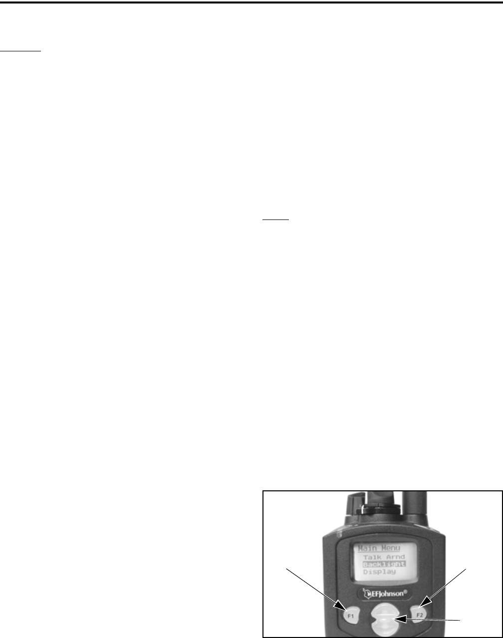
Menu Mode Buttons
When the menu mode is used, the F1 and F2
switches become dedicated menu mode control
Menu
Exit
Back/ Menu
Select/
Enter
Menu
Scroll
Up/Down

RADIO-WIDE FEATURES
19
switches. The F1 switch is Back/Clear, and the F2
switch is Menu Select/Enter. If the menu mode is
disabled, these switches can be programmed for other
functions.
Only the enabled menu items which apply to the
selected channel type are displayed. For example, if a
conventional channel is selected, only the enabled
functions for conventional channels are displayed.
When in the menu mode, messages continue to be
received on the selected channel. However, the display
does not indicate who is calling. Pressing the PTT
switch exits the menu mode and keys the transmitter.
The menu mode operates as follows:
1. To select the menu mode, press the F2 key. Up to
three menu parameters are then displayed as shown
in the preceding photo.
2. To scroll up or down through the menu parameter
list, press the Up/Down switch. The selected
parameter is indicated by a dark bar.
3. To display the available modes for a highlighted
parameter, press the F2 switch. The currently
selected mode is indicated by an asterisk.
4. Press the Up/Down switch to highlight the desired
mode. Then press the F2 key to select that mode.
5. To step back to the previous level or exit the menu
mode, press the F1 (Clear) key.
4.3 TIME-OUT TIMER
The time-out timer disables the transmitter if it is
keyed continuously for longer than the programmed
time. It can be programmed for 15 seconds to 3
minutes, 45 seconds or it can be disabled.
If the transmitter is keyed for longer than the
programmed time, the transmitter is disabled, a contin-
uous tone sounds, and “TX TIMEOUT” is displayed.
Five seconds before time-out occurs, a warning beep
sounds to indicate that time-out is approaching. The
timer and tone are reset by releasing the PTT switch.
A different time can be programmed for each
system, and the timer can be enabled or disabled on
each conventional channel. With conventional chan-
nels, a penalty time may also be programmed that
prevents transmissions for a certain time after the
transmitter is disabled (see Section 5.6).
One use of this feature is to prevent a channel
from being kept busy for an extended period by an
accidentally keyed transmitter. It can also prevent
possible transmitter damage caused by transmitting for
an excessively long period.
4.4 HOME ZONE/CHANNEL SELECT
If the Home Zone option switch or menu param-
eter is programmed, it selects the preprogrammed
home zone. The selected channel is displayed if the
channel switch is enabled, and the preprogrammed
home channel is selected if it is disabled. The trans-
ceiver is also programmed so that either the home or
last selected zone is selected when power is turned on.
Refer to Section 3.3 for more information.
4.5 POWER OUTPUT SELECT
Each conventional channel and SMARTNET/
SmartZone and P25 Trunked system can be
programmed for high, low, or switchable power. If the
High/Low Power option switch or menu parameter is
programmed and selectable power is programmed on
the current channel or system, high and low trans-
mitter power can be selected. All models support high
and low power.
The new level is flashed in the display as either
“HI POWER” or “LOW POWER”. If selectable
power is not permitted on the current channel,
“FIXED LOW” or “FIXED HIGH” is flashed and no
change occurs. The selected power level for a channel
is permanent until it is manually changed again. The
low power mode may be automatically selected during
a low battery condition (see Section 3.4).
4.6 ALERT TONE SELECT
The various alert tones that sound are described
in Section 7.1. These tones can be turned on and off if
the Alert Tone option switch or Tones menu parameter
is programmed. When all tones are off, “TONE OFF”
is momentarily displayed, and when all tones are on,
“TONE ON” is momentarily displayed. If this switch
or menu parameter is not programmed, tones are fixed
* This feature requires 51xx operating (Flash) software
1.9.0 or later and PCConfigure 1.20 or later.

RADIO-WIDE FEATURES
20
Table 4-1 Programmable Option Switch and Menu Mode Functions
Function Menu
Display
Available in Mode: See Descript.
in Section:
Conv. P25 Trk SMARTNET SmartZone
Alert tones On-Off TonesXXXX4.6
Backlight On-Off BacklightXXXX3.5
Call Alert Select Call AlertXXXX5.16.6, 6.7
Call Response Select Call Rsp X X X 6.5
Change Keyset Chg Keyset X 8.2.10
Channel Select Chan SelctXXXX3.3
Clear/Secure Select SecurityXXXX8.1.7
Clone Select (menu only) Clone X 5.14
Configure (menu only)ConfigXXXXNot curr. used
Digital Talk Group Select Select TG X 5.16
Display Information Select Display X 5.9
Emergency Select EmergencyXXXX
5.10, 6.10
Erase Keys (menu only)Erase KeysXXXX8.2.10
High/Low Power SelectTx PowerXXXX4.5
Home Zone SelectHome ZoneXXXX4.4
Key Select Key Select X 8.2.10
Keypad Lock Select (Opt sw only) X X X X 3.6
Keypad Programming Select Keypad Prg X 5.17
Messaging Message X X X 5.16.7, 6.8
Monitor Mode Select Monitor X 5.3
Normal/Selective Select Squelch X 5.5
OTAR Rekey Request OTAR Rekey X 8.2.10
Phone Call Select Phone X X 6.6
Priority Channel Select Priority X 5.11.3
Private Call Select Priv Call X X 6.5
Radio Wide Scan SelectRW ScanXXXX4.8
Repeater Talk-Around Select Talk Arnd X 5.8
Scan Mode Select ScanXXXX4.8
Scan List Edit SelectScan EditXXXX4.8
Scan List Select Scan SelctXXXX4.8
Squelch Select List Sqlch Code X 5.5
Single Tone Encoder Tone Encdr X 5.15
Site Lock Select Site Lock X X 6.14
Site Search Select Site Srch X X 6.14
Status Select StatusXXXX5.16.8, 6.9
Surveillance Mode SelectSurv ModeXXXX4.7
Tone Volume Edit Tone VolXXXX4.6
Unit Call Select Unit Call X X 5.16
Unprogrammed (not used)-XXXX -
Volume Down (Opt sw only)XXXX3.1.3
Volume Up (Opt sw only)XXXX3.1.3

RADIO-WIDE FEATURES
21
in the on or off mode by programming. If the Surveil-
lance mode is programmed (see following), tones are
totally disabled.
The Alert Tone volume** can be adjusted relative
to the volume control setting. This is done by
programming and also by the user if the Tone Volume
Adjust option button or menu parameter is
programmed. Relative levels of –170 to +170 can be
set with “0” the default setting. A minus value
decreases the tone volume and a plus value increases
it. The user adjusted level permanently overrides the
programmed level if applicable.
4.7 SURVEILLANCE MODE
If the Surveillance mode* is programmed, the
backlight, all alert tones, and front panel LED indi-
cator are totally disabled in all operating modes. This
feature can be turned on and off** by the user if the
Surveillance Mode option button or menu parameter
are programmed. The user selected mode permanently
overrides the programmed mode if applicable.
4.8 SCANNING
4.8.1 INTRODUCTION
Scanning monitors the channels in the scan list
for messages that the transceiver is programmed to
receive. When a message is detected, scanning stops
and the message is received. Shortly after the message
is complete, scanning resumes (unless it has been
disabled).
There are two basic scan modes available: Stan-
dard and Radio Wide. The operation of the standard
type is unique to the type of channel selected, and the
operation of Radio Wide type is the same regardless of
the type of channel selected. Only one type can be
enabled at a time. For example, if standard scanning is
enabled and radio wide scanning is selected, standard
scanning is automatically disabled and vice versa.
More information on these types of scanning follows.
4.8.2 STANDARD SCANNING
Standard scanning monitors only channels that
are the same type as that currently selected. For
example, if a conventional channel is selected, only
conventional channels are scanned and likewise for
SMARTNET/SmartZone and Project 25 Trunked
channels. More information on how standard scan-
ning operates in these modes is located in the
following sections:
Conventional Mode - Section 5.11
Other Modes - Section 6.12
Standard scanning is turned on and off by the
Scan option switch or menu parameter as follows. If
this switch or menu parameter is not programmed,
standard scanning is not available.
•Enable scanning using the Scan option switch or
menu parameter. Scanning is enabled when the
icon is displayed.
•To turn scanning off, press the Scan option switch
again or select “Off” in the scan menu. Scanning is
disabled when the icon is no longer displayed.
•If the zone or channel is changed while scanning is
selected, scanning continues on the same or a
different scan list (see “Standard Mode Scan Lists”
on page 22).
NOTE: Each SMARTNET/SmartZone and P25 trunked
channel can be programmed so that scanning is auto-
matically enabled when the channel is selected.
4.8.3 RADIO WIDE SCANNING
NOTE: Use radio wide scanning only if two types of
channels need to be scanned at the same time such as
conventional and SMARTNET/SmartZone. Otherwise,
use the more efficient standard scanning because there
is less chance of missed calls.
Radio wide scanning monitors the channels in the
preprogrammed radio-wide scan list. This scan list can
include up to 16 channels of any type and assigned to
any zone (see “Radio Wide Scan List” on page 22).
Radio wide scanning is turned on and off by the Radio
Wide Scan option switch or menu parameter as
follows. If this switch or menu parameter is not
programmed, radio wide scanning is not available.
* This feature requires 51xx operating (Flash) software
1.5.0 or later and PCConfigure 1.17 or later. ** This feature requires 51xx operating (Flash) software
1.9.0 or later and PCConfigure 1.20 or later.

RADIO-WIDE FEATURES
22
•Enable Radio Wide Scanning using the Radio Wide
Scan option switch or menu parameter. As with
standard scanning, radio wide scanning is indicated
when the icon is displayed.
•To turn radio wide scanning off, press the Radio
Wide Scan option switch again or select “Off” in the
menu. Scanning is disabled when the icon is no
longer displayed.
•If the zone or channel is changed while radio wide
scanning, scanning continues normally.
4.8.4 SCAN HOLD TIME
When a message is received or transmitted while
scanning, there is a delay before scanning resumes.
The delay after receiving a call prevents another
message from being received before a response can be
made. The delay after transmitting a call ensures that a
response is heard instead of another message occurring
on some other channel.
Separate delay times are programmable for Radio
Wide and Standard scanning. With radio wide and
conventional standard scanning, delays of 0-7.5
seconds are programmable in 0.5-second steps. With
SMARTNET/SmartZone and P25 Trunked standard
scanning, a scan delay of 2-10 seconds can be
programmed in 0.5-second steps.
4.8.5 TRANSMITTING IN THE SCAN MODE
When the transmitter is keyed while scanning is
enabled, the transmission may occur on various
channels as follows.
Conventional Operation - Transmissions can be
programmed to occur on the priority, selected, or
receive channel. Refer to Section 5.11 for more
information.
SMARTNET/SmartZone/P25 Trunked Operation - If
scanning is halted to receive a message, program-
ming determines if transmissions occur on the
selected or active channel. Transmissions at other
times occur on the selected channel.
4.8.6 NUISANCE CHANNEL ADD/DELETE
With standard scanning, channels can be tempo-
rarily deleted from the scan list, for example, if
messages become annoying. This feature is not avail-
able with radio wide scanning. Channels can also be
permanently added or deleted from a scan list as
described in Section 4.9.5. Proceed as follows to
temporarily delete a nuisance channel:
NOTE: The selected channel and also priority chan-
nels cannot be deleted from the scan list.
1. While receiving a message on the channel to be
deleted, press and hold the Scan option switch until
a tone sounds (about 1 second).
2. The channel is then deleted and scanning of the
remaining channels in the scan list resumes.
3. Deleted channels are added back into the scan list if
any of the following occur:
•Scanning is turned off and then on again using the
Scan option switch or menu parameter.
•Transceiver power is turned off and then on again.
•The selected channel is changed.
4.9 SCAN LISTS
4.9.1 STANDARD MODE SCAN LISTS
NOTE: The selected channel is always scanned.
A scan list is simply the channels that are scanned
when scanning is enabled. With all operating modes,
as many standard scan lists as are required can usually
be programmed (up to 256). The only limitation is the
available memory. Each scan list can include up to 256
channels/talk groups (or optionally up to 512). Refer
to Sections 4.9.4 and 4.9.5 which follow for informa-
tion on selecting and editing standard scan lists.
4.9.2 RADIO WIDE SCAN LIST
With radio wide scanning, there is only one scan
list available regardless of the type of channel selected,
and it is not user programmable. This scan list can
contain up to 16 channels of any type. For example, it
could include six conventional channels and ten
SMARTNET/SmartZone channels.

RADIO-WIDE FEATURES
23
4.9.3 DETERMINING WHICH CHANNELS ARE
IN SCAN LIST
The channels in the radio-wide and conventional
scan lists are indicated as follows. Channels in the
SMARTNET/SmartZone/P25 Trunked lists are indi-
cated only when editing a scan list.
1. To view the conventional scan list, enable standard
scanning using the Scan switch or menu parameter.
Likewise, to view the radio wide scan list, enable
radio wide scanning using the Radio Wide Scan
switch or menu parameter. Also select the scan list
if applicable as described in the following
“Selecting a Scan List” description.
2. Select the desired zone and then scroll through the
channels by rotating the channel switch. When the
displayed channel is in the scan list (scanned
normally), the icon is displayed.
4.9.4 SELECTING A SCAN LIST
NOTE: Only standard scan lists are selectable.
With conventional operation, selecting another
conventional channel does not change the scan list.
However, the scan list can be temporarily changed by
the user if the Scan (List) Select option switch or menu
parameter is programmed (see following). The
programmed default scan list is automatically
reselected on power up.
With SMARTNET/SmartZone operation and
Project 25 trunked operation, each channel (talk
group) can be programmed to select one of the
programmed lists or so that scanning is disabled (No
List). In addition, each channel can be programmed so
that scanning is automatically enabled (Auto Scan)
when it is selected. If the Scan (List) Select option
switch or menu parameter is programmed, the list that
is selected by all talk and announcement groups in the
current system can be temporarily changed by the user
as follows. “No List” (scanning disabled) or
“Programmed” (default list) can also be selected if
desired). The programmed default scan list is automat-
ically reselected on power up.
Change the currently scan list as follows.
1. With scanning disabled ( icon not displayed),
press the Scan List option switch or select the Scan
Selct menu parameter.
2. The currently selected list is displayed as “List x”,
where “x” is the currently selected list. To exit
without changing the selected list, simply press the
Scan List option switch again or the F1 key.
3. To select another list, press the Up/Down switch.
When the desired list is displayed, select it and exit
this mode by pressing the Scan List option switch
again or the F1 or F2 key.
4.9.5 EDITING A SCAN LIST
If the Scan Edit option switch or menu parameter
is programmed, conventional, SMARTNET/
SmartZone, and P25 Trunked standard scan lists can
be user programmed as follows. Changes are perma-
nent (cycling power does not reselect a default
condition).
1. Make sure that both standard and radio wide scan-
ning are off ( icon not displayed). Select a
conventional or SMARTNET/SmartZone/P25
Trunked channel corresponding to the scan list
being programmed.
2. Select the scan edit mode using the Scan Edit option
switch or menu parameter. This mode is indicated
by in the display.
3. If applicable, select the list to be edited by pressing
the Up/Down switch. Select the desired list by
pressing the F2 key. The selected list is indicated as
“LIST x”. If user programming is disabled on a list,
(conventional only) “NO EDIT” is momentarily
displayed and it cannot be edited.
4. Select the channel you want to add or delete by
pressing the Up/Down switch. After the last channel
in the current zone is displayed, the first valid
channel in the next zone is displayed and vice versa.
Lists are limited to 256 channels (or optionally up to
512). If an attempt is made to add more than 256 or
512, “LIST FULL” is displayed and a channel must
be deleted before another can be added.

24
CONVENTIONAL MODE FEATURES
NOTE: Priority channels can be deleted.
5. If the selected channel is in the scan list (scanned),
the icon is displayed. To change the status of
the displayed channel, press the F2 (Enter) switch.
With conventional channels only, if the selected
scan list is programmed with fixed priority
channel(s), the next press of F2 makes the current
channel the priority channel indicated by . If
dual priority channels are used, pressing F2 again
makes it the second priority channel indicated by
. Then pressing F2 again takes the channel out
of the scan list. Refer to Sections 5.11.3 and 5.11.4
for more information on priority channel sampling.
6. To exit this mode and save the changes, press the F1
(Exit) key or the Scan Edit option switch again.
2
SECTION 5 CONVENTIONAL MODE FEATURES
5.1 INTRODUCTION
An overview of the conventional operating mode
is located in Section 3.8.2. The following information
describes the features unique to analog and digital
(Project 25) conventional operation. Refer to the
preceding “Radio Wide Features” section (4) for infor-
mation on features common to all operating modes.
5.2 MONITORING BEFORE TRANSMITTING
With conventional operation, you may need to
manually monitor the channel before transmitting to
make sure that it is not be used by someone else. If
you were to transmit while someone else was using the
channel, you would probably disrupt their conversa-
tion. With SMARTNET/SmartZone and P25 Trunked
operation, monitoring is performed automatically.
Monitor conventional channels automatically or
manually as follows:
Automatic Channel Monitoring
If the selected channel is programmed for Busy
Channel Lockout (also called Transmit Disable On
Busy), monitoring is performed automatically. Refer
to Section 5.4 for more information on this feature.
Manual Channel Monitoring
The automatic monitoring just described may
occasionally disable the transmitter when the channel
is not in use, such as if the repeater has extended hang
time. In this case, you may not want to use it and the
channel must then be monitored manually as follows:
Busy Indicator - With scanning disabled, note if the
multi-function indicator on the front panel is steady
green. If it is not, the channel is not being used and a
call can be transmitted. It it is green, a carrier is being
detected, so the channel may be busy (see following).
Monitor Mode - There may be times when a busy
condition is indicated even though no one is using the
channel. Monitoring should then be performed by
disabling Call Guard squelch (or group ID detect on
Project 25 channels). This is usually done by selecting
the Monitor Mode (see following) or by the Normal/
Selective option switch or menu parameter (see Section
5.5.5).
5.3 MONITOR MODE
The monitor mode unsquelches the receiver and
monitors the channel even if a carrier is not detected.
Other features of this mode are as follows:
•Call Guard (CTCSS/DCS) squelch is disabled on
analog channels and NAC and group ID detect are
disabled on P25 (conventional) channels.
•Busy Channel Lockout is overridden (see next
section)
•Scanning temporarily halts
The Monitor Mode operates as follows:
1. To monitor the transmit frequency for activity
before transmitting, briefly press the Monitor option
switch or select the Monitor menu “Tx Channel”
parameter. The icon is then displayed to indicate
the monitor mode and the receiver unsquelches.

CONVENTIONAL MODE FEATURES
25
2. To monitor the receive frequency instead, press and
hold the Monitor option switch until a tone sounds
or approximately 2 seconds, or select the Monitor
menu “Sqlch Ovrd” parameter. This can be used, for
example, to improve reception if intermittent
squelching is making a weak message difficult to
understand.
3. To disable the monitor mode and return to normal
operation, press the Monitor option switch again of
select the Monitor menu “Off” parameter.
The Normal/Selective function disables Call
Guard squelch and P25 group ID detect but not
scanning and P25 NAC detect (see Section 5.5.5).
5.4 BUSY CHANNEL LOCKOUT
The Busy Channel Lockout feature (also called
Transmit Disable on Busy) automatically disables the
transmitter if the channel is busy when the PTT switch
is pressed. When the transmitter is disabled by this
feature, “BUSY” is displayed, a busy tone sounds, and
the transmitter is disabled.
The Busy Channel Lockout feature can be
programmed to operate as follows. Each conventional
channel can be programmed differently.
Off - Busy channel lockout is disabled and the trans-
mitter keys even if the channel is busy.
Noise - If a carrier is detected on the channel, the
transmitter is disabled when the PTT switch is pressed.
Tone (NAC) - If an incorrect Call Guard (CTCSS/
DCS) or NAC code (see Section 5.16) is detected, the
transmitter is disabled when the PTT switch is pressed.
An incorrect code is any code other than the one
programmed for the current channel.
If Busy Channel Override is permitted by
programming, it is possible to transmit even when the
transmitter is disabled by this feature. Simply release
the PTT switch and then quickly press it again.
5.5 CALL GUARD SQUELCH
5.5.1 INTRODUCTION
Tone or digital Call Guard squelch (also called
CTCSS/DCS signaling) can be programmed on each
conventional analog transmit and receive channel in
any order desired. The reverse burst and turn-off code
are always transmitted and also detected on channels
programmed with Call Guard squelch.
The Call Guard squelch feature eliminates
distracting messages intended for others using the
channel. This is done by using a subaudible tone or
digital code to control the squelch. This tone or code is
unique to a user or a group on that channel. This tone
or code is transmitted with the voice signal but is not
heard because it is in the subaudible range and is atten-
uated by a filter. Call Guard squelch must be used in
both the transmitting and receiving transceiver to be
functional.
5.5.2 CALL GUARD SQUELCH ENABLE/
DISABLE
The Normal/Selective option switch or menu
parameter (if programmed) can be used to disable
receive Call Guard squelch on analog channels or
group ID code detection on P25 channels. When selec-
tive squelch is disabled, “Sq Normal” is flashed in the
display, and when it is enabled, “Sq Select” is flashed.
When “Normal” is selected, the receiver
unsquelches only if a carrier is detected, and scanning
and Project 25 NAC detection are not disabled. The
selected mode is in effect until it is manually changed
again. Selecting another channel or cycling power
does not reselect a default condition.
5.5.3 TONE CALL GUARD SQUELCH
Tone-type Call Guard squelch utilizes subaudible
CTCSS tones from 67-254.1 Hz. Although there are 42
tones assigned, those above 33 (210.7 Hz) are normally
not used because of their close proximity to the voice
band which starts at 300 Hz. In addition, tones 11 (97.4
Hz), 39 (69.3 Hz), 40 (206.5 Hz), 41 229.1 Hz), and 42
(254.1 Hz) are normally not used because they may
cause interference with adjacent tones.

CONVENTIONAL MODE FEATURES
26
A reverse burst is transmitted when the push-to-
talk switch is released and also detected when calls are
received. It is a 180-degree phase reversal for a period
of time determined by the tone frequency, and it elimi-
nates the squelch tail (noise burst) in the receiving
transceiver. Both the transmitting and receiving trans-
ceiver must be equipped with this feature for it to be
utilized.
5.5.4 DIGITAL CALL GUARD SQUELCH
Digital Call Guard squelch (DCS) uses digital
data instead of subaudible tones to control the squelch.
This data consists of continuous repetitions of 23-bit
words. No bit or word synchronization information is
used. When the push-to-talk switch is released, a turn-
off code is transmitted which eliminates the squelch
tail similar to the reverse burst.
Although there are thousands of possible code
combinations with 23 bits, only 83 are unique with the
data scheme used. The number specified when the
code is programmed is actually a seed for a special
algorithm used to generate the 23-bit data word. The
data is transmitted at a rate of 134.4 bits per second.
Therefore, approximately six words are transmitted
each second. When the data is decoded, 23-bit samples
are taken and then the bits are rotated to determine if a
valid code was received.
5.5.5 SELECTIVE SQUELCH CODE SELECT
(CTCSS/DCS/NAC)
NOTE: Call Guard codes can be permanently repro-
grammed by keypad programming (see Section 5.17).
A different CTCSS/DCS/NAC squelch code can
be temporarily selected if the Selective Squelch option
switch or menu parameter and a CTCSS/NAC code
list have been programmed. This feature allows the
normal transmit and receive Call Guard programming
to be temporarily overridden with a code selected from
this list.
The CTCSS/DCS/NAC list is programmed with
up to sixteen tone (CTCSS) or digital (DCS) Call
Guard codes. In addition, for operation on Project 25
channels, each position can be programmed with an
NAC code.
When the Call Guard code is changed using this
feature, it remains selected even if other channels are
selected. However, if transceiver power is cycled or a
talk-around channel is selected, the normal codes are
reselected. When scanning, the selected code also
applies to all scanned channels. If both analog and
digital (Project 25) channels can be selected or
scanned, the CTCSS/DCS code for the selected posi-
tion is used for analog channels and the NAC code for
the selected position is used for P25 channels. If a
channel is programmed for mixed mode operation, the
selective squelch type (analog or digital) programmed
for the transmit mode determines the selective squelch
type used.
Proceed as follows to select a preprogrammed
Call Guard code:
1. Press the Selective Squelch option switch or select
the Sqlch Code menu mode parameter. Then press
the Up/Down switch to select the desired code. The
display indicates “SEL SQ xx” where, “xx” is the
selected code from 1-16.
2. To select the displayed code and return to the normal
display, press the F2 (Select) key or the Selective
Squelch switch again.
3. To check which code is selected, press the Selective
Squelch switch once to display the current selection
and then again to return to normal operation.
4. To return to the normal selective squelch codes,
select “DEFAULT” in this mode. As previously
described, the normal codes are also automatically
reselected whenever transceiver power is cycled or
a talk-around channel is selected.
5.6 PENALTY TIMER
A penalty timer may be programmed on conven-
tional systems to prevent transmissions for the
programmed time after the time-out timer disables the
transmitter (see Section 4.3). The penalty timer can be
programmed for the same times as the time-out timer,
and timing starts when the PTT switch is released. If
the PTT switch is pressed during the penalty time, the
time-out indication occurs again and the transmitter
remains disabled. When the penalty timer expires, a
beep sounds and the transmitter can be keyed.

CONVENTIONAL MODE FEATURES
27
5.7 CONVERSATION TIMER
A conversation timer can be programmed on
conventional systems in addition to the time-out timer
(see Section 4.3). This timer limits the total length of a
conversation rather than just the length of each trans-
mission as with the time-out timer. The following is
more information on this timer.
•It can be programmed for times up to 7.5 minutes.
•It is reset when the time between transmissions
exceeds the time programmed for the penalty timer.
•A warning beep sounds 5 seconds before this timer
disables the transmitter.
•When this timer disables the transmitter, a contin-
uous tone sounds and the red transmit indicator
turns off. The PTT switch must then be released
until the penalty timer expires (indicated by a beep).
5.8 REPEATER TALK-AROUND
Normally, all transmissions go through a repeater
which usually increases range. However, there may be
times when a mobile is out of range of the repeater and
therefore unable to talk to anyone even though the
mobile being called is only a short distance away. To
allow communication in this situation, repeater talk-
around can be selected. Transmissions then occur on
the receive frequency which permits direct mobile-to-
mobile communication.
Repeater talk-around can be selected if the RTA
option switch or menu parameter is programmed.
When talk-around is enabled by this switch, is
displayed. This feature remains enabled during scan-
ning, and changing channels or turning power off does
not change the selected condition. Talk-around is
available on conventional channels only.
5.9 DISPLAYING TRANSMIT/RECEIVE
FREQUENCY
If the Displayed Information option switch or
menu parameter is programmed (see Section 4.1), it can
be used to display the channel frequency in megahertz.
Pressing this switch toggles between displaying the
standard channel alias and the channel frequency. The
receive frequency is displayed when receiving and the
transmit frequency is displayed when transmitting. This
feature is available on conventional channels only.
5.10 EMERGENCY ALARM AND CALL
NOTE: The following enhanced conventional emer-
gency features require 5100 operating (Flash) soft-
ware 1.8.0 or later and PCConfigure 1.19 or later.
5.10.1 INTRODUCTION
Emergency Alarms and Calls are separate func-
tions that can be individually enabled or disabled on
each analog and P25 conventional system. The Emer-
gency option switch or menu parameter is required for
these functions. Emergency Alarms and Calls are
transmitted on the last selected talk group.
The emergency hot microphone function can also
be programmed with emergency alarms and calls.
Then when the emergency switch is pressed, the
microphone audio is enabled and the transmitter auto-
matically keyed for the programmed hot microphone
time (10-120 seconds). If “silent” emergency is
programmed, no tones sound but the transmit indicator
still lights. If the “Surveillance Mode” is enabled (see
Section 4.7), all indicators, lights, and tones are
disabled.
5.10.2 EMERGENCY ALARMS
An emergency alarm is a special transmission on
the selected talk group that alerts a dispatcher of an
emergency situation. It is sent by simply pressing
Emergency option switch or selecting the Emergency
menu parameter on channel of a system programmed
for emergency alarms.
In the P25 conventional mode, a special emer-
gency data transmission is sent, and in the conven-
tional analog mode, it is a DTMF number that is sent
in place of the Pre/Post ANI programming if appli-
cable. If ANI is not programmed, it defaults to the
“Pre” condition. The DTMF Emergency ID is
programmed on the Conventional Radio Wide screen
when programming the radio. Proceed as follows to
activate an emergency alarm:
1. Select a channel of a system on which the Emer-
gency Alarm is enabled and then press the Emer-
gency option switch or select that menu parameter.
The radio then begins automatically transmitting an
emergency alarm and “EMERGNCY” is indicated
in the display for 3 seconds.

CONVENTIONAL MODE FEATURES
28
2. When the emergency alarm is acknowledged, “ACK
RCVD” is briefly displayed and the emergency
acknowledge tone (two beeps) sounds. This alert
tone can be disabled if desired. Silent operation may
also be programmed in which case no tone sounds
and there is no indication that an acknowledgment
occurred.
3. The radio continues to transmit this message until an
acknowledgment is received or until 30 attempts
have been made. To exit this mode, power must be
turned off.
5.10.3 EMERGENCY CALLS
An emergency call occurs if the PTT switch is
pressed after pressing the Emergency switch or
selecting the menu parameter as above and the system
of the selected channel is programmed for emergency
calls.
If the PTT switch is pressed on a P25 channel, an
emergency indication is sent according to the P25
standard (the emergency bit is set in the Common Air
Interface). If it is pressed on an analog channel, the
DTMF emergency ID is sent in place of the ANI
DTMF PTT ID if applicable. To place this call,
proceed as follows:
1. Select a channel of a system on which the Emer-
gency Call is enabled and press the Emergency
option switch or select that menu parameter.
2. To place the emergency call, manually press the
PTT switch and begin speaking as with a standard
call. If the channel is changed, operation continues
on the new channel in the emergency mode.
3. To exit this mode, power must be turned off.
5.11 CONVENTIONAL MODE SCANNING
5.11.1 GENERAL
Channel scanning features common to all oper-
ating modes are described in Sections 4.8 and 4.9. The
following information describes features unique to
conventional operation.
5.11.2 TRANSMITTING IN SCAN MODE
Each conventional scan list can be programmed
for one of the following modes. These modes deter-
mine if priority sampling occurs and also the channel
on which transmissions occur while scanning. Refer to
the next section for more information on priority
sampling.
No Priority - No priority channel sampling occurs
when the list is selected. The radio transmits on the
selected channel.
Priority/Tx Selected - Priority sampling occurs and
the priority channel or channels are those programmed
in the selected scan list. The radio transmits on the
selected channel.
Priority/Tx Priority (1) - Priority sampling occurs
and the priority channel or channels are those
programmed in the selected scan list. The radio trans-
mits on the priority (1) channel.
Priority (1) on Selected - The priority (1) channel is
always the selected channel. The radio transmits on
the selected channel.
Talkback - No priority sampling occurs. The radio
transmits on the channel of a call while scanning is
halted. Then once scanning resumes, it transmits on
the selected channel.
5.11.3 PRIORITY CHANNEL SAMPLING
NOTE: The following describes priority sampling
when scanning conventional channels. Priority
sampling when scanning SMARTNET/SmartZone/P25
Trunked channels is described in Section 6.12.
General
The priority channel sampling feature ensures
that when standard scanning, messages on the priority
channel are not missed while listening to a message on
some other channel. The transceiver can be
programmed as just described so that the priority
channel is a fixed channel programmed in the current
scan list, the currently selected channel, or not used.

CONVENTIONAL MODE FEATURES
29
NOTE: Priority channel sampling (both analog and
P25 channels) currently does not occur when
receiving encrypted calls, and also when receiving
P25 calls if equipped with Flash code 1.10 or earlier.
In addition, the priority channel is not scanned if the
active channel is an analog channel on the same
frequency programmed with CTCSS/DCS squelch
control.
Either a single or dual priority* channels can be
programmed if desired. With dual priority, a call on
the second priority channel is interrupted by a call on
the first priority channel but not vice versa. When
scanning and the selected channel is a single or first
priority channel, is indicated in the display. This
indication is displayed regardless of whether the
priority channel is fixed or always the selected
channel. When it is a second priority channel, is
displayed.
The priority channel sampling frequency is deter-
mined by the programmed Priority Lookback Time A
(see description which follows). For example, if 2.0
seconds is programmed, the priority channel is
sampled every 2.0 seconds when listening to a
message on a non-priority channel. When not listening
to a message, the priority channels are scanned in the
normal scan sequence. With dual priority, the first and
second priority channels are alternately sampled at the
Lookback Time.
Priority channel sampling occurs only with stan-
dard conventional scanning. It does not occur with
radio-wide scanning, when listening to any type of
SMARTNET/SmartZone/P25 trunked call, encrypted
call, or when transmitting (see preceding note). A
series of “ticks” may be heard when the priority
channel is sampled while listening to a message on
some other conventional channel.
The priority sampling times are programmed by
the following parameters:
Lookback Time A - This time determines how often
the priority channel is checked for activity. Times of
0.25-4.00 seconds in 0.25-second steps can be
programmed.
Lookback Time B - This time determines how often
the priority channel is checked once an incorrect Call
Guard (CTCSS/DCS) or NAC code is detected. Since
it takes much longer to detect an incorrect Call Guard
signal than a carrier, this time should be relatively long
to prevent the interruptions from making a message
difficult to understand. Times of 0.5-8.0 seconds can
be programmed in 0.5-second steps.
5.11.4 CHANGING THE PRIORITY CHANNEL
If a fixed priority channel is associated with the
current scan list, it can be changed if the Priority
option switch or menu parameter is programmed. With
dual priority, this function changes only the first
priority channel. To change both priority channels, use
the Scan List Edit function described in Section 4.9.5.
Proceed as follows to change the priority channel
using the Priority option switch/menu parameter:
1. Make sure scanning is disabled ( icon not
displayed) and the desired scan list is selected (see
Section 4.9).
2. Select the channel you want to be the priority
channel and then press the Priority option switch or
select that menu parameter. “Priority” is then
flashed to indicate that the current channel is now
the priority channel when scanning that list. Other
indications that may occur are as follows:
•If “No Priority” is displayed, priority sampling
may not be enabled on the scan list.
•If “Sel Chan” is displayed, the priority channel is
always the selected channel and cannot be
changed.
•If no indication displayed, the scan list may not be
user editable or the channel may not be in the scan
list.
5.12 STANDARD CONVENTIONAL CALLS
Standard conventional calls are placed to other
mobile units monitoring the selected channel. The
proper coded Call Guard squelch tone or code or P25
NAC may need to be transmitted by your radio for
them to receive a call (see Sections 5.5 and 5.16.3).
2
* This feature requires 51xx operating (Flash) software
1.5.0 or later and PCConfigure 1.17 or later.

CONVENTIONAL MODE FEATURES
30
Placing a Standard Conventional Call
1. Turn power on and set the volume as described in
Section 3.1. Select the channel programmed for the
mobile you want to call as described in Section 3.3.
2. Monitor the channel automatically or manually as
described in Section 5.2.
3. Press the PTT switch and if the Busy Channel
Lockout feature is programmed on the channel (see
Section 5.4), the transmitter is automatically
disabled if the channel is busy. Otherwise, busy and
out-of-range conditions are not indicated.
4. Press (and hold) the PTT switch to talk and release
it to listen.
Receiving a Standard Conventional Call
1. Select or scan the channel programmed for the call
you want to receive (refer to Sections 4.8 and 4.9 for
more scanning information).
2. When the call is received, press the PTT switch to
talk and release it to listen. If scanning, responses
may occur on the priority, selected, or receive
channel as described in Section 5.11.2.
5.13 DTMF/ANI SIGNALING
DTMF (Dual Tone Multi-Frequency) tones can
be generated for ANI (Automatic Number Identifica-
tion) and other purposes on conventional analog chan-
nels. One of the following options may be enabled on
each channel:
Pre-Tx ANI - A preprogrammed ANI sequence is
automatically sent each time the PTT switch is
pressed.
Post-Tx ANI - A preprogrammed ANI sequence is
automatically sent each time the PTT switch is
released.
When an emergency alarm or call is placed, this
ANI signaling is replaced by the Emergency DTMF
ID (see Section 5.10).
5.14 CLONE MODE
The Clone feature* enables one radio to program
another with identical information. The PCConfigure
programming software is not required. This feature is
available with 51xx portables only. Other requirements
are as follows:
•The Clone menu parameter must be selectable by
the master (sending) radio. This parameter is not
required with the slave (receiving) radio.
•The master and slave radios must be identical
models (same frequency range and options).
•Flash code Version 1.5.0 or higher is required with
both radios (the version number is display briefly at
power up). PCConfigure Version 1.17 or higher is
also required to program the Clone menu parameter.
Only zones with conventional analog and P25
channels can be transferred using this function. Any
SMARTNET/SmartZone and P25 trunked informa-
tion is not transferred. In addition, the P25 Unit ID,
encryption keys, and the RSI ID and other OTAR
information is not transferred. Cloned zones are indi-
cated in the slave radio by an asterisk in the first char-
acter position of the zone alias.
Proceed as follows to program a radio using this
feature:
1. Turn the slave (receiving) radio off and connect it to
the master (sending) radio using Cloning Cable, Part
No. 023-5100-930. Turn the slave radio back on.
2. On the master radio, select the Clone menu param-
eter and press the F2 key. Either the “Zone” or
“Complete” mode can then be selected. Operation in
these modes is as follows:
Zone - This mode allows channel information for
only the selected zones to be transferred. Informa-
tion programmed on the Global, Radio Wide, and
By System screens is not changed. A list of the
available conventional zones is displayed, and then
to select a zone, highlight it and press the F2 key. A
selected zone is indicated by an asterisk (*). After
the desired zones are selected, scroll to “OK” and
press F2 to begin the data transfer.
* This feature requires 51xx operating (Flash) software
1.5.0 or later and PCConfigure 1.17 or later.

CONVENTIONAL MODE FEATURES
31
Complete - This mode transfers all conventional
programming information from the master radio.
This includes information on the Global, Radio
Wide, and By System screens. Simply highlight
“Complete” and press the F2 key to begin the data
transfer.
5.15 SINGLE TONE ENCODER
This feature allows the user to transmit a single
tone by pressing the Single Tone Encoder option
switch or selecting that menu parameter. Each conven-
tional system can be programmed for a tone of 500-
2500 Hz in 1 Hz steps with a duration of 0.5-2.5
seconds in 0.1 second steps. This feature is available
only with Flash code 1.7.0 or later.
5.16 PROJECT 25 MODE FEATURES
5.16.1 UNIT ID CODE
Each transceiver that operates on Project 25
(digital) channels is programmed with an eight-digit
unit ID. This ID is unique for each transceiver and can
be any number from 1-16,777,216. When power is
turned on with a Project 25 channel selected, this ID is
briefly displayed.
5.16.2 GROUP ID CODE
Each Project 25 channel is programmed with a
group ID that determines which group of mobiles will
receive the call. A call is received on a channel if a
selected or scanned channel is programmed with that
ID and the correct NAC is detected (see following).
Group IDs can be any number from 0-65,535. Group
ID detect can be disabled by the Normal/Selective
squelch function described in Section 5.5.2 or the
monitor mode described in Section 5.3
5.16.3 NETWORK ACCESS CODE
Project 25 conventional channels also use a NAC
(Network Access Code) to control which calls are
received on a channel. The NAC can be 0-4095, and
each transmit and receive channel can be programmed
for a different code. Other operation, such as moni-
toring before transmitting, is similar to that of analog
channels. NAC (and group ID) detect can be disabled
by the monitor mode described in Section 5.3.
5.16.4 P25 GROUP CALLS
P25 group calls are placed by simply selecting the
channel programmed for the desired group, monitoring
the channel if required, and transmitting.
Changing a Channel Talk Group
If the Digital Talk Group Select option switch or
Select TG menu parameter is programmed, the talk
group assigned to a channel can be changed by the
user. The new talk group continues to be assigned to
the channel until it is manually changed again (cycling
radio power or selecting another channel does not
reselect a default talk group). Change the talk group
assigned to a channel as follows:
1. Select the channel to be changed and then press the
Talk Group Select option switch or select the Select
TG menu parameter.
2. Press the Up/Down switch until the alias (alphatag)
of the desired talk group is displayed.
3. To select that talk group and return to normal oper-
ation, press the Talk Group Select option switch
again or the F2 switch. If talk group selection has
been disabled on the channel by programming, “NO
LIST” is displayed, a tone sounds, and no change
occurs.
5.16.5 P25 UNIT CALLS
Unit Calls (also called Individual Calls) can be
placed to a specific radio on a Project 25 channel if the
Unit Call option switch or menu parameter is
programmed. Only the individual ID of the target
radio is sent (a talk group ID is not sent). The mobiles
that can be called are preprogrammed in the unit call
list.
To receive a Unit Call, the RF channel of the call
must be selected or scanned and the correct NAC and
unit ID must be detected. The ID of the calling mobile
is then transmitted back. To respond to the call, the
transceiver must be programmed with the Unit ID
option switch or menu parameter, and have a Unit Call
programmed for the ID of the calling mobile.
* This feature requires 51xx operating (Flash) software
1.9.0 or later and PCConfigure 1.20 or later.

CONVENTIONAL MODE FEATURES
32
Place and receive a Unit Call as follows:
1. To transmit a Unit Call, press the Unit Call option
switch or select the Unit Call menu parameter. The
alias (tag) of the last Unit Call is displayed.
2. If required, press the Up/Down switch to display the
desired call. The alias and ID of the calls that have
been programmed are alternately displayed.
3. Press and then release the PTT switch. Ringing is
then heard and “WAIT” displayed to indicate that
the mobile is being rung. To disable this ringing but
not the call, briefly press the PTT switch again.
Ringing occurs for 20 seconds or until the call is
answered, whichever occurs first.
4. When a Unit Call is received, two beeps sound (if
tones are enabled), and “Call Rcvd” and the alias or
frequency of the currently selected talk group are
alternately flashed.
In addition, the transceiver can be programmed to
display the alias of the talk group on which the call
is being received (if it is not the same as the selected
talk group) and/or the ID of the mobile placing the
call. The time each is displayed is programmable**
for 0.5-7.0 seconds or infinite.
5. To respond, select the Unit Call mode by pressing
the Unit Call option switch or selecting the menu
parameter. The following operation then occurs:
•If a unit call has been programmed with the ID of
the calling mobile, it is automatically selected. A
response can then be made without changing the
selected channel.
•If no Unit Call has been programmed with the ID
of the calling mobile, a response cannot be made
in this mode.
•If the call timer times out (set by programming) or
the channel is changed before a response is made,
the unit call mode is exited.
5.16.6 CALL ALERT
General
The Call Alert™ feature* allows pages to be sent
and received on P25 conventional channels. Opera-
tion is similar to SMARTNET/SmartZone and P25
Trunked channels.
Answering a Page
1. When a page is received, five beeps sound and
“PAGE” is displayed. The ID of the mobile paging
you is stored as the last ID received.
2. To clear or ignore the page, press any option switch.
If the PTT switch is pressed, a group call is placed
on the selected channel.
3. To answer the page as a unit call (see Section
5.16.5), press the Unit Call option switch or select
that menu parameter and the alias of the mobile
paging you is displayed. Press the PTT switch and
respond. One of the following conditions then
occur:
•If the mobile being called is on the air, ringing is
heard until the called party answers or for 20
seconds, whichever occurs first. If no answer
occurs within 20 seconds, a continuous tone
sounds and “NO ANS” is displayed.
•If the mobile being called is not on the air, a
continuous tone is heard instead of ringing and
“NO ACK” is displayed.
4. When the call is finished or if it could not be
completed for some reason, end it by pressing the
Unit Call option switch or the F1 (Exit) key.
Initiating a Page
1. With a P25 conventional channel selected, momen-
tarily press the Call Alert option switch or select that
menu parameter. The alias of the last ID called is
displayed.
2. If required, press the Up/Down switch to display the
desired mobile. The alias of each number is
displayed.
* This feature requires 51xx operating (Flash) software
1.8.0 or later and PCConfigure 1.19 or later. ** This feature requires 51xx operating (Flash) software
1.9.0 or later and PCConfigure 1.20 or later.
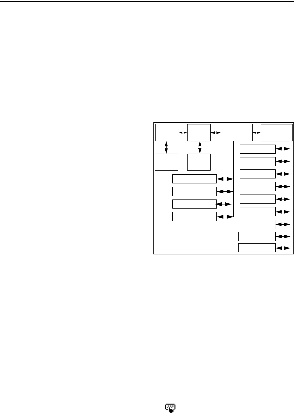
CONVENTIONAL MODE FEATURES
33
3. Press the PTT switch or the F2 key and one of the
following occur:
•If five beeps sound, the system received the page
and the paged mobile is on the air and received it.
The page mode is automatically exited.
•If the system received the page but the called
mobile is not on the air, a single beep sounds and
“NO ACK” is displayed 6 seconds after the PTT
switch is pressed. Auto exit then occurs.
5.16.7 MESSAGING
The messaging feature* allows preprogrammed
messages to be sent to a dispatcher on P25 channels.
Up to 16 messages can be preprogrammed, and they
are identified by an alias. If a Message option switch
or menu parameter is programmed, messages are sent
as follows:
1. Momentarily press the Message option switch or
select that menu parameter. The alias of the last
message sent is displayed.
2. If required, press the Up/Down switch to display the
desired message. Then send the message by
pressing the F2 key or momentarily pressing the
PTT switch. One of the following events then
occurs:
•If five beeps sound and “ACK RECVD” is
displayed, the message was received and automat-
ically acknowledged by the system.
•If after five tries the message is not acknowledged,
a tone sounds and “NO ACK” is displayed.
5.16.8 STATUS MESSAGING
The status feature* allows you to manually or
automatically send your current status to your
dispatcher on P25 channels. Up to eight status condi-
tions can be preprogrammed, and they are identified
by an alias. If the Status option switch or menu param-
eter is programmed, status conditions are sent as
follows:
1. Momentarily press the Status option switch or select
that menu parameter. The alias of the current status
condition is displayed.
2. To change the current status, press the Up/Down
switch until the desired status is displayed. Then to
send the status, press the F2 (Select) switch or
momentarily press the PTT switch. One of the
following events then occurs:
•If five beeps sound and “ACK RCVD” is
displayed, the status was received and acknowl-
edged by the system.
•If after five tries the message is not acknowledged,
a tone sounds and “NO ACK” is displayed.
Figure 5-1 Keypad Programming Menu
Flowchart
5.17 KEYPAD PROGRAMMING
NOTE: The Keypad programming feature is available
to Federal Government users only. Users regulated by
the Federal Communications Commission are not
allowed to have this feature.
5.17.1 INTRODUCTION
Keypad programming can be enabled only with
transceivers that have been factory coded as Federal
models. It is then available if a conventional mode
option switch or menu parameter is programmed for
the “Keypad Programming” function. The keypad
programming mode is indicated by “CHNG ZONE”
and in the display.
Zone Channel
Change
Change System
Parameters Channel
Parameters
Select
Zone
Select
Channel
Scan Hold Timer
Tx Timer
Penalty Timer
Conver. Timer
Rx Freq
Tx Freq
Rx Code/NAC
Tx Code/NAC
Tx Power
Tx Tmr On-Off
Squelch Adj*
Chan Spacing*
F1 = Select F2 = Exit/Back
Up/Down = Scroll
Tlk Grp Sel**
* Analog Only ** Digital Only
* This feature requires 51xx operating (Flash) software
1.8.0 or later and PCConfigure 1.19 or later.

CONVENTIONAL MODE FEATURES
34
Keypad programming allows conventional
channel parameters such as the transmit and receive
frequency and Call Guard squelch code to be changed.
In addition, several conventional mode timers can be
changed. It cannot be used to reprogram disabled
channels or any SMARTNET/SmartZone/P25
Trunked information.
5.17.2 MENU DESCRIPTION
A menu system is used to select parameters in the
keypad programming mode. A flowchart showing the
keypad programming mode menu structure is located
in Figure 5-1. When the keypad programming mode is
selected by the Keypad Programming option switch or
menu parameter, the first menu parameter “CHNG
ZONE” is displayed as just described. Press the Up/
Down switch to scroll through the available parame-
ters which are listed below.
•CHNG ZONE
•CHNG CHAN
•SYS PARMS
•CHAN PARMS
Press the F2 (Select) key to select a highlighted
parameter, and press the F1 key from one of the main
menus to exit keypad programming. Pressing it in the
other menus returns to the previous menu. Additional
information on this parameters is located in the
following sections.
5.17.3 ZONE PASSWORD
NOTE: Make sure that the zone password(s) are not
lost because they cannot be overridden in the field.
The PCConfigure software must be used to display the
lost password or program a new password.
Each zone can be programmed with a password
by the PCConfigure software to prevent unauthorized
reprogramming of zone by keypad programming.
When this password is programmed, it must be entered
before system or channel parameters in that zone can
be changed by keypad programming. The zone pass-
word is programmed in the Zones > Edit Zone screen
of the PCConfigure programmer. This screen is
displayed by clicking the Edit Zone button. A different
password can be programmed for each zone.
When an attempt is made to select a system or
channel parameter in a password protected zone,
“PASSWORD” is flashed. The password is always
eight digits long and is entered using the same proce-
dure as used for the power-up password described in
Section 3.2. After the password is entered, system and
channel parameters for that zone can be reprogrammed
normally.
5.17.4 ZONE CHANGE PARAMETER
The “CHNG ZONE” menu parameter selects the
zone containing the conventional channel to be repro-
grammed. It does not change the zone selected for
normal operation.
Press the F2 switch to select the “ZONE CHG”
parameter and then scroll through the programmed
zones by pressing the Up/Down switch. When the
desired zone is displayed, select it by pressing the F2
switch.
5.17.5 CHANNEL CHANGE PARAMETER
The “CHNG CHAN” menu parameter selects the
conventional channel to be reprogrammed. Disabled or
SMARTNET/SmartZone/P25 Trunked channels
cannot be selected. This does not change the channel
selected for normal operation.
Press the Select switch to select the “CHNG
CHAN” parameter and then scroll through the
programmed channels by pressing the Up/Down
switch. When the desired channel is displayed, select it
by pressing F2 switch.
5.17.6 SYSTEM PARAMETERS
NOTE: If “PASSWORD” is briefly displayed when
attempting to select a parameter, see Section 5.17.3.
The “SYS PARMS” menu parameter selects the
conventional mode timers to be reprogrammed (see
following). Press the F2 switch to select the “SYS
PARMS” parameter and then press the Up/Down
switch to display the desired parameter. Then press the
F2 switch again to select it.
SCAN TIMER - Selects the Scan Hold timer.
Press the Up/Down switch to increment/decrement

CONVENTIONAL MODE FEATURES
35
the timer in 0.5-second steps or set it to 0 seconds
to disable it. When the desired value is displayed,
store it by pressing the F2 switch.
TX TIMER - Selects the transmit time-out timer.
Press the Up/Down switch to increment/decrement
the timer in 15-second steps or disable it by
selecting 0 seconds. When the desired value is
displayed, store it by pressing the F2 switch.
PEN TIMER - Selects the penalty timer. Press the
Up/Down switch to increment/decrement the timer
in 15-second steps. When the desired value is
displayed, store it by pressing the F2 switch.
CONV TIMER - Selects the conversation timer.
Press the Up/Down switch to increment/decrement
the timer in 30-second steps or disable it by
selecting 0 seconds. When the desired value is
displayed, store it by pressing the F2 switch.
5.17.7 CHANNEL PARAMETERS
NOTE: If “ENTER PSWD” is briefly displayed when
attempting to select a parameter, see Section 5.17.3.
The “CHAN PARMS” menu parameter selects
the following conventional channel parameters that
can be reprogrammed. Press F2 switch to select the
“CHAN PARMS” parameter and then press the
Up/Down switch to display the desired parameter.
Then press the F2 switch to select it. The squelch
control parameters are unique to the type of conven-
tional channel selected (analog or Project 25).
RX FREQ - Programs the receive channel frequency.
The digit being changed flashes, and press the Up/
Down switch to select the desired number for that
digit. Then press the F2 switch to move to the next
digit. If an invalid frequency is entered, a beep sounds,
“INVALID” is briefly displayed, and the number must
be re-entered.
TX FREQ - Programs the transmit frequency the
same as the preceding RX FREQ.
CTCSS/DCS Squelch Control (Analog Channel)
RX CODE - Programs the receive Call Guard
(CTCSS/DCS) code. The currently selected code
and is initially displayed. Press the Up/Down
switch to select the desired code type (CTCSS
analog or DCS digital Call Guard). Then press F2
to select it and enter the code number similar to
programming a channel frequency as just
described.
TX CODE - Selects the transmit codes the same as
RX CODE above.
NAC Squelch Control (Project 25 Channel)
RX NAC - Programs the Network Access Code
(NAC) which can be any number from 0-4095. The
procedure is similar to programming a RX FREQ
just described. If an invalid code is entered, a beep
sounds, “INVALID” is briefly displayed, and the
code must be re-entered.
TX NAC - Selects the transmit NAC the same as
RX NAC above.
TX POWER - Selects the desired power output level.
Press the Up/Down switch to scroll through the
following choices. When the desired setting is
displayed, store it by pressing the F2 switch.
•POWER HI - High transmit power
•POWER LO - Low transmit power
•POWER SW - Switchable power selectable by
the High/Low power switch. This choice is not
available if that switch is not programmed.
TX TIMER - Enables or disables the time-out timer
on the current channel. Press the Up/Down switch to
select the on and off mode, and when the desired
setting is displayed, store it by pressing the F2 switch.
CHAN SPC (Analog Only) - Selects either wide or
narrow band channel spacing. Press the Up/Down
switch to select “WIDE” or “NARROW”, and when
the desired setting is displayed, store it by pressing the
F2 switch.
SQ ADJ (Analog Only) - Changes the preset squelch
setting on that channel. The default setting is “0” and
values of –7 to +7 can be selected. Increasing this
setting toward +7 causes the squelch to open sooner so
that weaker signals can be received, and decreasing it
toward –7 causes the opposite to occur.

36
SMARTNET/SMARTZONE/P25 TRUNKED FEATURES
NOTE: The channel spacing is not set with P25 chan-
nels because it is always narrow, and the squelch
cannot be changed because the setting is critical for
proper receiver operation.
TG ID (P25 Only) - Selects the talk group for the
selected channel. Press the Up/Down switch to display
the alias of each preprogrammed talk group and then
store it by pressing the F2 switch.
SECTION 6 SMARTNET/SMARTZONE/P25 TRUNKED FEATURES
6.1 INTRODUCTION
An overview of the SMARTNET/SmartZone and
P25 Trunked operating modes is located in Section
3.8. The following information describes the features
unique to these modes of operation. Refer to the
“Radio Wide Features” section starting on page 18 for
information on features common to all operating
modes.
6.2 ANALOG AND DIGITAL OPERATION
Either analog or digital operation can be selected
for communication on SMARTNET traffic channels.
Each talk group can be programmed for either type of
operation. Digital operation may be an optional
feature.
6.3 VIEWING UNIT ID
When power is turned on with a SMARTNET/
SmartZone channel selected, the five-digit Unit ID
from 1-65,535 is briefly displayed as IDxxxxx. When
a P25 channel is selected, the eight-digit unit ID from
1-16,777,216 is briefly displayed (see Section 5.16.1).
6.4 STANDARD GROUP CALLS
6.4.1 INTRODUCTION
Standard group calls may be placed to another
mobile, group of mobiles, or a dispatcher, depending
on programming. Most calls are probably this type.
Proceed as follows to place and receive group calls:
6.4.2 PLACING A STANDARD GROUP CALL
1. Turn power on and set the volume as described in
Section 3.1. Select the channel programmed for the
talk group you want to call (see Section 3.3).
2. If the talk group is programmed for encryption and
is not strapped to Clear or Coded, select the desired
mode by pressing the Clear/Secure option switch or
selecting that menu parameter. The status cannot be
changed if the talk group is strapped to Clear or
Coded. Refer to Section 8.1.7 for more information.
3. Press the PTT switch and begin talking. An optional
talk permit tone may sound to indicate when talking
can begin. Events that may occur are as follows:
•If in the secure mode and your transceiver is not
programmed with the proper encryption key,
“KEYFAIL” is displayed and the call must be
made in the clear mode or the proper key must be
programmed.
•If the busy tone sounds and “BUSY” is displayed,
the system is busy. Release the PTT switch and
wait for the call back tone to sound. Then press
the PTT switch within 3 seconds.
•If a continuous tone sounds and “NO SYS” is
displayed, you may be out-of-range. Drive closer
or away from shielding objects and try again.
•If your unit ID is invalid, the call is being made to
an invalid group ID, or group calls are not
enabled, “DISABLED ID” is displayed and an
alert tone sounds.
•If an attempt is made to change an analog call
from the clear to secure mode and there is no
available secure channel, “NO SEC” is flashed,
an error tone sounds, and the call is terminated.
•If an attempt is made to change an analog channel
from the secure to clear mode, “SEC ONLY” is
displayed, an error tone sounds, and the call is
terminated. (Calls on digital channels can be
changed if not strapped to clear or secure.)

SMARTNET/SMARTZONE/P25 TRUNKED FEATURES
37
•If the secure mode is selected by the Secure/Clear
option switch or menu parameter and an attempt
is made to transmit on a channel strapped as clear,
“Clear Only” is displayed and the transmitter is
disabled. Likewise, if the clear mode is selected
and the channel is strapped as secure, “Secure
Only” is displayed and the transmitter is disabled.
6.4.3 RECEIVING A STANDARD GROUP CALL
Calls are received on only the talk group and/or
announcement group programmed for the selected
channel (with scanning disabled). When the selected
channel is programmed with both Talk and Announce-
ment groups, only the Talk and Announcement group
IDs are detected. Other IDs in the Announcement
group are detected only if no talk group is
programmed.
The display indicates the selected channel alias
when a call is received. The transceiver can also be
programmed so that the received talk group alias and/
or Individual ID of the calling mobile are displayed.
The received talk group alias and the selected talk
group alias are alternately displayed if they are
different, and the Individual ID of the calling mobile is
displayed briefly when the call is received. The time
each is displayed is programmable* for 0.5-7.0
seconds or infinite.
6.5 PRIVATE (UNIT-TO-UNIT) CALLS
NOTE: With P25 Trunked operation, these calls are
called Unit Calls, and they function the same as
Enhanced Private Conversation calls described in the
following information.
6.5.1 GENERAL
Private calls allow calls to be placed to a specific
mobile unit. Either the Enhanced Private Conversa-
tion™ or standard Private Conversation modes may be
programmed depending on the capabilities of the radio
system. One difference between these call types is that
the Enhanced type provides an indication that the
called mobile is not on the air and the standard version
does not. Operation in each of these modes is
described in the following information.
The Private Call option key is required to place
these calls, and either that key or the Call Response
option key is required to receive them. Private calls are
programmed to operate in one of the following modes:
•Disabled
•Answer-only capability
•List only - Unit IDs can be selected from a prepro-
grammed list only (direct entry using the keypad is
not allowed)
•Unlimited - Unit IDs can be selected from a list
and also dialed directly entered using the keypad.
Both limited and DTMF keypad models can be
programmed to recall the unit IDs from a prepro-
grammed list. However, only DTMF keypad models
can be programmed to directly dial unit IDs.
6.5.2 PLACING AN ENHANCED PRIVATE
CONVERSATION CALL
Recalling From List
1. Momentarily press the Private Call option key or
select that menu parameter and the alias of the last
called mobile is displayed. The private call mode is
indicated by in the display.
2. If required, select another mobile by pressing the
Up/Down switch until the alias of the desired
mobile is displayed.
3. Press the PTT switch of the F2 key to initiate the
call.
(Proceed to the bulleted list which follows Item 3 in
the next section for events that may occur next.)
Direct Entry Using DTMF Keypad
1. Press and hold the Private Call option key until a
tone sounds (approximately 1 second). The last ID
called is displayed, and the private call mode is indi-
cated by in the display.
2. Using the 0-9 keys, dial the ID of the mobile you are
calling (five digits must be entered). To erase the last
digit, press the Down key, and to cancel the call,
press the Private Call Option key again.
* This feature requires 51xx operating (Flash) software
1.9.0 or later and PCConfigure 1.20 or later.

SMARTNET/SMARTZONE/P25 TRUNKED FEATURES
38
3. Press the PTT switch to initiate the call. If the
entered number is valid, the display indicates the
alias of the ID if it matches an ID in the call list.
Otherwise, the ID you entered continues to be
displayed.
Events that may then occur are as follows:
•If the mobile being called is on the air, “WAIT” is
displayed and ringing is heard until the called
party answers or for 20 seconds, whichever occurs
first. Pressing the PTT switch or an option key
stops the ringing but not the call. When the call is
answered, the voice of the called party is heard.
•If the called mobile does not answer within 20
seconds, a continuous tone sounds and “NO ANS”
is displayed.
•If the called mobile is not on the air, a continuous
tone sounds instead of the ringing tone and “NO
ACK” is displayed.
•If the busy tone sounds and “BUSY” is displayed,
the called mobile has answered the call but the
system is busy. When the system is no longer busy,
the call back tone sounds.
•If your transceiver or the called transceiver is
inhibited or not programmed to make this type of
call or for the requested secure mode, “Rspns
Only” is displayed and an alert tone sounds.
•If your transceiver does not have the proper
encryption key, “KEYFAIL” is displayed and the
call must be made in the clear mode by pressing
the Clear/Secure option key (if strapped to switch-
able). Otherwise, load the correct key.
4. When the call is finished or is not answered, end it
by pressing the Private Call option key or the F1
(Exit) key.
6.5.3 PLACING A STANDARD PRIVATE
CONVERSATION CALL
Recalling From List
1. Momentarily press the Private Call option key or
select that menu parameter. The alias of the last
called mobile is displayed, and the private call mode
is indicated by in the display.
2. If required, select another mobile by pressing the
Up/Down switch until the alias of the desired
mobile is displayed.
3. Press the PTT switch or the F2 key to initiate the
call.
(Proceed to the bulleted list which follows Item 3 in
the next section for events that may occur next.)
Direct Entry Using DTMF Keypad
1. Press and hold the Private Call option key until a
tone sounds (approximately 1 second). The last ID
called is displayed, and the private call mode is indi-
cated by in the display.
2. Using the 0-9 keys, dial the ID of the mobile you are
calling (all six digits). To erase the last digit, press
the Down key, and to cancel the call, press the
Private Call Option key again.
3. Press the PTT switch to initiate the call. If the
entered number is valid, the display indicates the
alias of the ID if it matches an ID in the call list.
Otherwise, the ID you entered continues to be
displayed.
Events that may then occur are as follows:
•The called party answers the call.
•The called party does not answer. Press the
Private Call option key or F1 (Exit) to end the
call.
•If the selected mobile ID is not valid, “INVALID
ID” is displayed and an alert tone sounds.
•If the radio system is busy, four low tones sound
and “BUSY” is displayed. When the system is no
longer busy, the call back tone (four beeps) is
heard and the channel is automatically acquired.
Press the PTT switch to continue the call.

SMARTNET/SMARTZONE/P25 TRUNKED FEATURES
39
Available with future release
Available with future release
•If the call is in the secure mode and the transceiver
does not have the proper encryption key,
“KEYFAIL” is displayed and the call must be
made in the clear mode by pressing the Clear/
Secure option key or selecting that menu param-
eter (if strapped to switchable). Otherwise, load
the correct key.
4. When the call is finished or if it is not answered, end
it by pressing the Private Call option key or the F1
(Exit) key.
6.5.4 RECEIVING A PRIVATE CALL (ALL
TYPES)
1. When a private call is received, “CALL RCVD” is
displayed and the call tone sounds once.
2. To answer the call, press the Private Call option key
or select that menu parameter and then press the
PTT switch and begin speaking. The unit ID of the
calling mobile is displayed. More information
follows:
•If the PTT switch is pressed before the Private Call
option key, the call is transmitted as a group call.
•If private calls are not permitted (the Private Call
option key/menu parameter is not programmed),
press the Call Response option key or select that
menu parameter to answer the call.
•The call must be answered within 20 seconds or it
is automatically terminated.
•If the system is busy when a response is made,
“BUSY” is displayed and the busy tone sounds.
6.6 TELEPHONE CALLS
NOTE: Telephone calls are currently not available in
the P25 trunked mode or any secure mode.
6.6.1 GENERAL
The telephone call feature allows telephone calls
to be placed and received over the public telephone
system using your transceiver. Telephone calls are
programmed to operate in one of the following modes:
•Disabled
•Answer-only capability
•List only - Telephone numbers can be selected
from a preprogrammed list only (direct entry using
the keypad is not allowed)
•Unlimited - Telephone numbers can be selected
from a list and also dialed directly entered using
the keypad.
Both limited and DTMF keypad models can place
telephone calls by recalling the telephone number
from a preprogrammed list as just described. However,
only DTMF keypad models can directly dial telephone
numbers using the keypad.
6.6.2 PLACING A TELEPHONE CALL
Recalling From List
1. Momentarily press the Phone option key or select
that menu parameter. The alias of the last called tele-
phone number is displayed. The interconnect call
mode is indicated by in the display.
2. If required, press the Up/Down switch to display the
desired number. The alias of each number is
displayed.
3. Press and release the PTT switch and “DIALING” is
displayed. Events that may occur are as follows:
(Proceed to the bulleted list which follows Item 3 in
the next section for events that may occur next.)
Direct Entry Using DTMF Keypad
1. Press and hold the Phone option key until a tone
sounds (approximately 1 second). The alias of the
last called telephone number is displayed if it is in
the phone number list. Otherwise, the last eight
digits of the last called telephone number are
displayed. The interconnect call mode is indicated
by in the display.
2. Enter the telephone number using the 0-9, *, and #
keys. To enter a pause (indicated by “P”), press *
and then #. To erase the last digit, press the F1 key.
The number scrolls to the left in the display so that
the eight right-most digits are always displayed.
Numbers up to sixteen digits (including pauses) can

SMARTNET/SMARTZONE/P25 TRUNKED FEATURES
40
be entered. Press the Phone option key to cancel the
call.
3. Press and release the PTT switch and “DIALING” is
displayed. Events that may occur are as follows:
•If the access is successful, a dial tone sounds and
the dialed number is displayed and sent. Either
ringing or a busy signal is then heard as with a
standard telephone call. When the called party
answers, press the PTT switch to talk and release it
to listen (since the transceiver is half-duplex, it is
not possible to talk and listen at the same time).
Each time the PTT switch is released, a go-ahead
tone is sent to the landside party to indicate when
they can respond. To dial a number after the
connection is made, press the PTT switch and dial
the number using the microphone keypad.
•If the selected telephone number is not valid,
“INVALID” is displayed and an alert tone sounds.
Select a valid number.
•If the system is busy, “BUSY” is displayed and the
busy tone sounds. The call will automatically
proceed when the system becomes available.
•If you are out-of-range or the radio cannot be
accessed for some reason, “NO PHONE” is
displayed and an alert tone sounds.
•If the interconnect call you are making or the
selected secure mode is not authorized, “REJECT”
is displayed and an alert tone sounds.
•If your transceiver does not have the proper
encryption key, “KEYFAIL” is displayed and the
call must be made in the clear mode using the
Clear/Secure option key or menu parameter (if
encryption is selectable on the channel). Other-
wise, load the proper encryption key.
4. When the telephone call is finished or if it could not
be completed for some reason, end it by pressing the
Phone option key or F1 (Exit) key.
6.6.3 ANSWERING A TELEPHONE CALL
1. When a telephone call is received, “ringing” similar
to a standard telephone is heard and “PHONE” is
displayed.
2. To answer the call, press the Phone option switch or
select that menu parameter and press the PTT switch
to talk and release it to listen. Since the transceiver
operates half duplex, it is not possible to talk and
listen at the same time.
3. When the call is finished, end it by pressing the
PHONE option switch or F1 (Exit) key.
6.7 CALL ALERT
6.7.1 GENERAL
The Call Alert™ feature allows pages to be sent
and received. With SMARTNET/SmartZone opera-
tion, either the Enhanced Private Conversation™ or
Standard Private Conversation mode may be
programmed depending on the capabilities of the radio
system. With P25 Trunked operation, operation is
similar to the enhanced mode.
6.7.2 ANSWERING A PAGE
1. When a page is received, five beeps sound and
“PAGE” is displayed. The ID of the mobile paging
you is stored as the last ID received.
2. To clear or ignore the page, press any option switch.
If the PTT switch is pressed, a group call is placed
on the selected channel.
3. To answer the page as a private call (see Section
6.5), press the Private Call option switch or select
that menu parameter and the alias of the mobile
paging you is displayed. Press the PTT switch and
respond. One of the conditions that follow may also
occur:
Enhanced Private Conversation Mode
•If the mobile being called is on the air, ringing is
heard until the called party answers or for 20
seconds, whichever occurs first. If no answer
occurs within 20 seconds, a continuous tone
sounds and “NO ANS” is displayed.
•If the mobile being called is not on the air, a
continuous tone is heard instead of ringing and
“NO ACK” is displayed.
Available with future release
Available with future release

SMARTNET/SMARTZONE/P25 TRUNKED FEATURES
41
Standard Private Conversation Mode
•If the mobile being called is not on the air or does
not answer, you will simply not hear a response.
4. When the call is finished or it could not be
completed for some reason, end it by pressing the
Private Call option switch or the F1 (Exit) key.
6.7.3 INITIATING A PAGE
1. With a SMARTNET/SmartZone channel selected,
momentarily press the Call Alert option switch or
select that menu parameter. The alias of the last ID
called is displayed.
2. If required, press the Up/Down switch to display the
desired mobile. The alias of each number is
displayed.
3. Press the PTT switch or the F2 key and one of the
following occur:
•If five beeps sound, the system received the page
and the paged mobile is on the air and received it.
The page mode is automatically exited.
•If the system received the page but the called
mobile is not on the air, a single beep sounds and
“NO ACK” is displayed 6 seconds after the PTT
switch is pressed. Auto exit then occurs.
6.8 MESSAGING
NOTE: This feature is not available with P25 trunked
operation.
The messaging feature allows preprogrammed
messages to be sent to a dispatcher. Up to 16 messages
can be preprogrammed, and they are identified by an
alias. If a Message option switch or menu parameter is
programmed, messages are sent as follows:
1. Momentarily press the Message option switch or
select that menu parameter. The alias of the last
message sent is displayed.
2. If required, press the Up/Down switch to display the
desired message. Then send the message by
pressing the F2 key or momentarily pressing the
PTT switch. One of the following events then
occurs:
•If five beeps sound and “ACK RECVD” is
displayed, the message was received and automat-
ically acknowledged by the system.
•If after five tries the message is not acknowledged,
a tone sounds and “NO ACK” is displayed.
6.9 SENDING STATUS CONDITIONS
The status feature allows you to manually or
automatically send your current status to your
dispatcher. Up to eight status conditions can be prepro-
grammed, and they are identified by an alias. If the
Status option switch or menu parameter is
programmed, status conditions are sent as follows:
1. Momentarily press the Status option switch or select
that menu parameter. The alias of the current status
condition is displayed.
2. To change the current status, press the Up/Down
switch until the desired status is displayed. Then to
send the status, press the F2 (Select) switch or
momentarily press the PTT switch. One of the
following events then occurs:
•If five beeps sound and “ACK RCVD” is
displayed, the status was received and acknowl-
edged by the system.
•If after five tries the message is not acknowledged,
a tone sounds and “NO ACK” is displayed.
6.10 EMERGENCY ALARM AND CALL
6.10.1 INTRODUCTION
Emergency Alarms and Calls are separate func-
tions that can be individually enabled or disabled on
each SMARTNET/SmartZone and P25 Trunked
system. The Emergency option switch (or menu
parameter) is also required for these functions. Emer-
gency Alarms are transmitted on the last selected talk
group, and Emergency Calls are transmitted on the
emergency talk group programmed on the selected
system (or the selected talk group if none is
programmed).

SMARTNET/SMARTZONE/P25 TRUNKED FEATURES
42
The emergency hot microphone function can be
programmed with emergency alarms and calls. Then
when the emergency switch is pressed, the microphone
audio is enabled and the transmitter keyed for the
programmed hot microphone time (10-120 seconds). If
“silent” emergency is programmed, no tones sound but
the transmit indicator still lights. If the “Surveillance
Mode” is enabled (see Section 4.7), all indicators,
lights, and tones are disabled.
6.10.2 EMERGENCY ALARMS
An emergency alarm is a special data transmis-
sion on the selected talk group that alerts a dispatcher
of an emergency situation (an emergency tone usually
sounds at the console). Proceed as follows to activate
an emergency alarm:
1. Select a SMARTNET/SmartZone or P25 Trunked
channel that has this feature enabled and then press
the Emergency option switch or select that menu
parameter. The radio then begins automatically
transmitting an emergency alarm data message and
“EMERGNCY” is indicated in the display for 3
seconds.
2. When the emergency alarm is acknowledged, “ACK
RCVD” is briefly displayed and the emergency
acknowledge tone (two beeps) sounds. Silent opera-
tion may also be programmed in which case no tone
sounds and there is no indication that an acknowl-
edgment occurred.
3. The radio continues to transmit this message until an
acknowledgment is received or the programmed
number of attempts have been made. To exit this
mode, power must be turned off.
6.10.3 EMERGENCY CALLS
An emergency call urgently requests access to a
voice channel (an emergency tone usually does not
sound at the console). To place this call, proceed as
follows:
1. Select a SMARTNET/SmartZone or P25 Trunked
channel that has this feature enabled and press the
Emergency option switch or select that menu
parameter. The emergency mode is indicated when
“ACK RCVD” is briefly displayed and then
“EMERGNCY” and the emergency talk group are
alternately displayed.
2. To place the emergency call, manually press the
PTT switch and begin speaking as with a standard
call. All group calls which follow are then emer-
gency calls (private, telephone, and call alert calls
are not allowed). If the channel is changed, the call
is made on the emergency talk group programmed
for the new channel.
3. To exit this mode, power must be turned off.
6.11 FAILSOFT OPERATION
If a failure occurs in the SMARTNET/Smart-
Zone or P25 Trunked system so that it cannot be used,
the system directs the transceiver to automatically
enter the failsoft mode. When in this mode, “FAIL-
SOFT” and the alias of the selected channel are alter-
nately displayed. A failsoft tone may also be heard,
depending on how the repeater is programmed.
When in the failsoft mode, operation is in the
conventional mode on the preprogrammed failsoft
channel (a different failsoft channel can be
programmed on each talk group). If a transmission is
attempted before a failsoft channel is located, a contin-
uous tones sounds until the PTT switch is released.
When the radio system returns to normal operation,
this is automatically detected and normal operation
resumes.
6.12 SMARTNET/SMARTZONE/P25 TRUNKED
SCANNING FEATURES
6.12.1 GENERAL
Scanning on a SMARTNET/Smartzone and P25
Trunked systems is called Priority Monitor Scan. The
following are unique features of this type of scanning.
For general scanning information applicable to all
operating modes, refer to Sections 4.8 and 4.9.
•Scanning is turned on and off by the Scan option
switch or menu parameter. Talk groups (channels)
can be programmed so that scanning automatically
starts when the talk group is selected (Autoscan).

SMARTNET/SMARTZONE/P25 TRUNKED FEATURES
43
•When responding to calls in the scan mode, the
programming of the Talkback Scan parameter deter-
mines if a response always occurs on the talk group
of the call (Active Group) or the Selected Group if
they are different. Transmissions at other times
always occur on the selected talk group.
•Each talk group can be programmed to select one of
the programmed scan lists or “No List” (scanning is
disabled). If scanning is enabled and the selected
channel does not permit scanning, it is automatically
enabled again when a channel is selected that
permits scanning.
•Up to 256 scan lists, each with up to 256 talk groups
from the same system can be programmed. The
selected scan list can be temporarily changed as
described in Section 4.9.4 and edited as described in
Section 4.9.5.
•In addition to calls on channels in the scan list,
pages, private/unit calls, and telephone* calls are
received while scanning. Private and telephone calls
are not interrupted by priority messages.
6.12.2 PRIORITY TALK GROUP SAMPLING
One talk group in the scan list can be designated a
priority talk group by programming or it can be the
selected talk group. When scanning, messages on a
non-priority talk group are interrupted by messages on
the priority talk group. Priority scanning must also be
supported at the system level for it to occur as
programmed in the radio.
6.13 DYNAMIC REGROUPING
The dynamic regrouping feature allows a
dispatcher to change the current talk group or switch
mobiles to a predefined regrouping channel to receive
an important message. When the console issues a
regroup order, the transceiver switches to the prepro-
grammed regroup talk group. If the lock mode was not
specified, the selected talk group can be manually
changed and the previous talk group is reselected if
power is cycled. If a locked regroup command is
received, the displayed talk group cannot be changed
manually or by cycling power. It can be changed only
after a clear order is received from the console.
Dynamic regrouping operates as follows:
1. When this command is received, alternating tones
sound and the transceiver automatically changes to
the regrouping channel and “DYN REGRP” is
displayed.
2. Manually select the channel corresponding to that
alias. If this is not done, transmission still occurs on
the new channel, but the alternating tones sound
each time the PTT switch is pressed.
3. Talk and listen as usual. The dispatcher cancels
dynamic regrouping which is indicated by a short
tone. If a standard channel is not selected after this
occurs, transmission is not allowed if the talk group
is assigned as a dynamic regrouping talk group only.
If it is assigned as a normal talk group, normal trans-
missions are allowed.
6.14 SMARTZONE AND P25 TRUNKED
UNIQUE FEATURES
6.14.1 INTRODUCTION
As described in Section 3.8.3, the SmartZone®
mode provides wide area coverage by allowing
roaming between SMARTNET and conventional sites.
The P25 Trunked mode can provide access to a single
trunked site or roaming between several trunked sites.
Operation in these modes is the same as just described
in the preceding sections (6.1-6.13) with the following
additional features:
6.14.2 BUSY OVERRIDE
The busy override feature is enabled at the system
level by the system manager and is not a program-
mable radio feature. It allows a call to be placed even
if not all sites you are calling have a free traffic
channel. The only sites guaranteed to be included are
the Critical Sites and the sites where a Critical User is
located. This feature operates as follows:
1. Assume that you have attempted to place a call and
the system was busy (“BUSY” displayed and busy
tone sounded).
2. Release the PTT switch and then press it for 5
seconds or more. If a chirp tone sounds with the PTT
switch pressed, busy override is occurring.
* Telephone calling is currently not available.

MISCELLANEOUS
44
NOTE: Remember that not all members of the talk
group are receiving your message. Missing
members will start receiving your message as
channels become available.
6.14.3 SITE TRUNKING
Site trunking occurs when a site can no longer
participate in wide area trunking. When site trunking
is occurring, the radio searches for other sites that may
provide wide area coverage. Site trunking ends when a
wide area coverage site is located, the current site is
operating again as a wide area coverage site, an out-of-
range condition occurs, or the failsoft mode is entered.
6.14.4 DETERMINING CURRENT SITE AND
SEARCHING FOR NEW SITE
To display the RSSI level of the current site, press
the Site Search option switch or select that menu
parameter. The display then indicates the current site
number as “SITE xx” and the RSSI level as “RSSI
xx”. This mode is then automatically exited.
To scroll through the other programmed sites,
press and hold the Site Search option switch while
“SITE xx” or “RSSI xx” is displayed. If site lock is on
when site search is entered (see following), the radio
will be locked on the new site when this function is
exited.
6.14.5 LOCKING/UNLOCKING A SITE
It is sometimes desirable to stay on a site. To
prevent the transceiver from searching for a new site,
lock it on the current site by pressing the Site Lock
option switch or selecting that menu parameter. The
display then momentarily indicates the site alias to
indicate that the current site is locked (“x” is the
current site number). To unlock the site, press the Site
Lock switch again or the F2 (Select) key and
“UNLOCK” is momentarily displayed.
SECTION 7 MISCELLANEOUS
7.1 SUPERVISORY TONES
Single Beep (Alert Tone)
•Power was turned on and a successful power-up
sequence occurred (Section 3.1).
•The time-out timer is about to expire or the penalty
timer has expired (Section 4.3).
•The conversation timer is about to expire (Section
5.7).
•The system received your page but the paged mobile
is not on the air (Section 6.7).
•Telephone interconnect is not operational (Section
6.6).
Continuous Tone (Invalid Condition)
•A transmission is being attempted on a conventional
channel programmed as receive-only.
•The transmitter is disabled by the busy channel
lockout feature (Section 5.4).
•The transmitter has been disabled by the time-out
timer feature (Section 4.3).
•The transmitter has been disabled by the conversa-
tion timer (Section 5.7).
•An out-of-range condition exists (SMARTNET/
SmartZone and P25 trunking only).
•A transmission is being attempted before the penalty
timer has expired (Section 5.6).
•Dynamic regrouping has been exited but the
dynamic regrouping channel is still selected
(Section 6.13).
Single Short Medium-Pitch Tone
•A valid key has been pressed.
Single Short Low-Pitch Tone
•An invalid key has been pressed.

MISCELLANEOUS
45
Medium Tone (No Acknowledge)
•The paged mobile did not acknowledge the page
(Section 6.7).
•The message that was sent has not been acknowl-
edged (Section 6.8).
•The status condition that was sent has not been
acknowledged (Section 6.9).
Five Beeps (Recurring)
•The page was received (Section 6.7).
Two Short Tones
•A private call was received (Section 6.5).
Five Beeps
•The paged mobile received the page and acknowl-
edged it (Section 6.7).
•The message that was sent has been received and
acknowledged (Section 6.8).
•The status condition that was sent has been received
and acknowledged (Section 6.9).
Four Beeps
•The emergency alarm condition was acknowledged
(Section 6.10).
•Four low tone beeps indicate call back mode (the
system is no longer busy)
Alternating Tone
•Dynamic regrouping has occurred (Section 6.13).
•Dynamic regrouping has occurred but the
regrouping channel is not selected (Section 6.13).
Busy Signal
•The radio system is busy or a busy condition exists
when making a telephone call.
Three Medium Pitch Tones
•A channel is available after a busy condition
occurred (SMARTNET/SmartZone only).
7.2 SYSTEM OPERATOR PROGRAMMING
As noted several times in this manual, program-
ming determines the availability and specific operation
of many features. This usually refers to the program-
ming performed by the PCConfigure programmer
when the radio was set up, not to any programming a
user can perform. If a feature is controlled by a front
panel option switch and that switch is not available, it
is probably not available.
If the Keypad Programming option switch is
available, you can reprogram some conventional
channel parameters. Refer to Section 5.17 for more
information.
7.3 SPEAKING INTO MICROPHONE
For best results, hold the transceiver about 1-2
inches from your mouth and speak at a normal conver-
sational level. Do not shout since it distorts your voice
and does not increase range. Make sure that the PTT
(push-to-talk) switch is pressed before you begin to
speak and released as soon as the message is complete.
7.4 OPERATION AT EXTENDED RANGE
When approaching the limits of radio range, the
other party may not be able to hear your transmissions
and there may be an increase in background noise
when messages are received. You may still be out of
range even though you can hear a message. The reason
for this is that the signal you are receiving is usually
transmitted at a higher power level than the one trans-
mitted by your transceiver. Communication may be
improved by moving to higher ground or away from
shielding objects such as tall buildings or hills.
7.5 LICENSING
A government license is usually required to
operate this transceiver on the air.
7.6 TRANSCEIVER SERVICE
If the transceiver is not responding to any key
presses, the keypad may be locked. Refer to Section
3.6 for more information.

MISCELLANEOUS
46
If “PASSWORD” is briefly displayed when
power is turned on and you are prompted to enter a
password, the Power-Up Password feature is enabled.
Refer to Section 3.2 for more information.
If “UNPROGRAMD” is displayed, the cause
could be any of the following:
•An unprogrammed channel is selected. Select a
programmed channel.
•The selected channel is programmed for an option
that is not installed or an error in programming was
detected. Reprogram the radio.
If no characters appear in the display, the battery
may be discharged or defective. Try another battery. If
some other problem is occurring, turn power off and
then on again to reset the control logic. Also make
sure that the controls are properly set. If it still does
not operate correctly, return it for service.
NOTE: There are no user-serviceable components in
the transceiver. Altering internal adjustments can cause
illegal emissions, void the warranty, and result in
improper operation that can seriously damage the
transceiver.