E F Johnson 2425313 VHF Mobile Radio User Manual 5300 ES Operating Manual

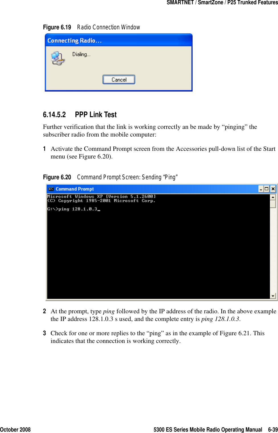
E. F. Johnson Company VHF Mobile Radio 5300 ES Operating Manual
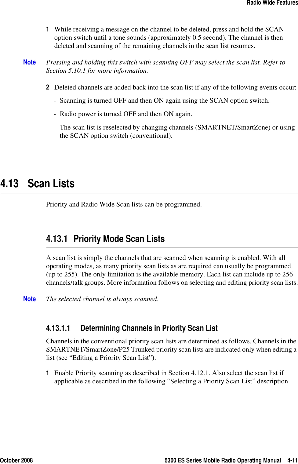
5300 ES OM with FCC part 15
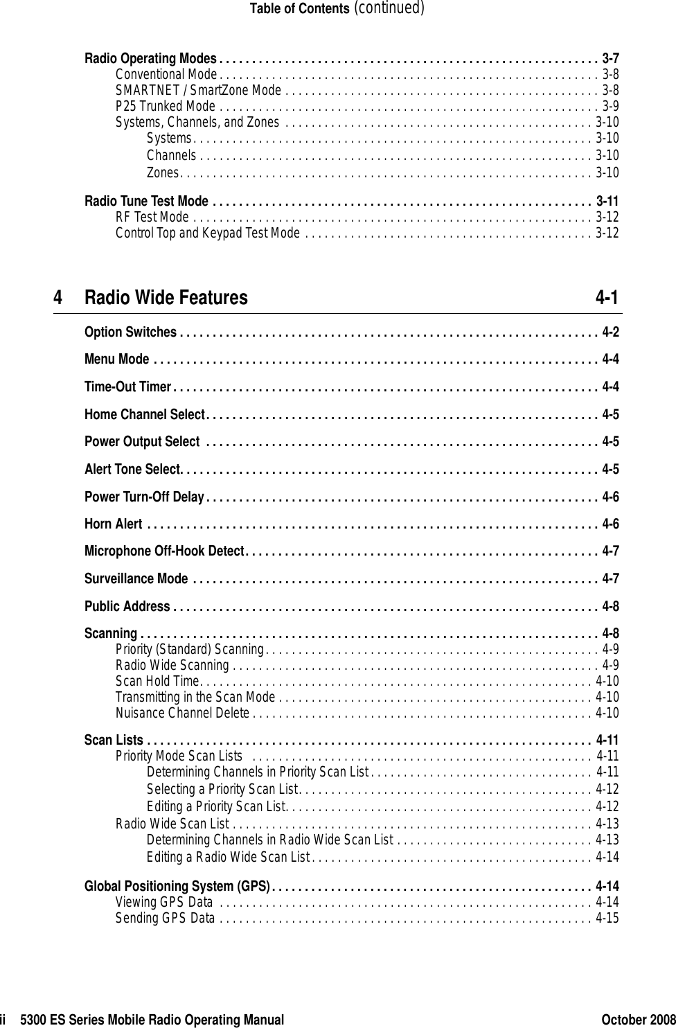
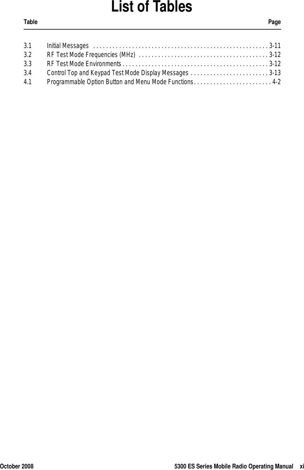
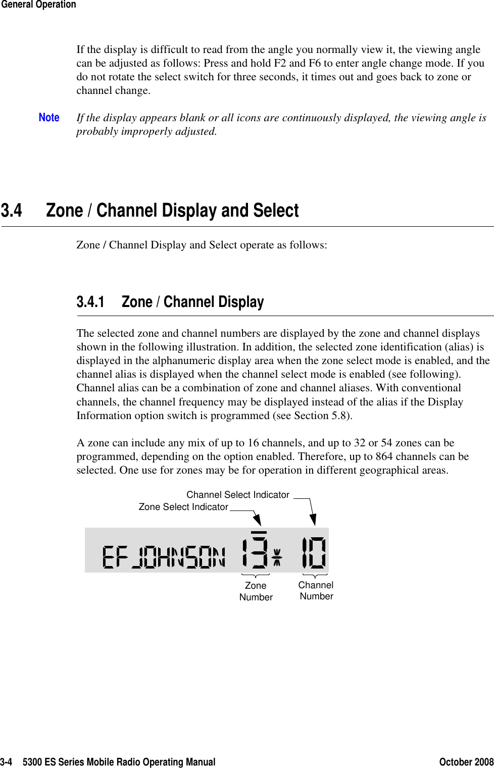
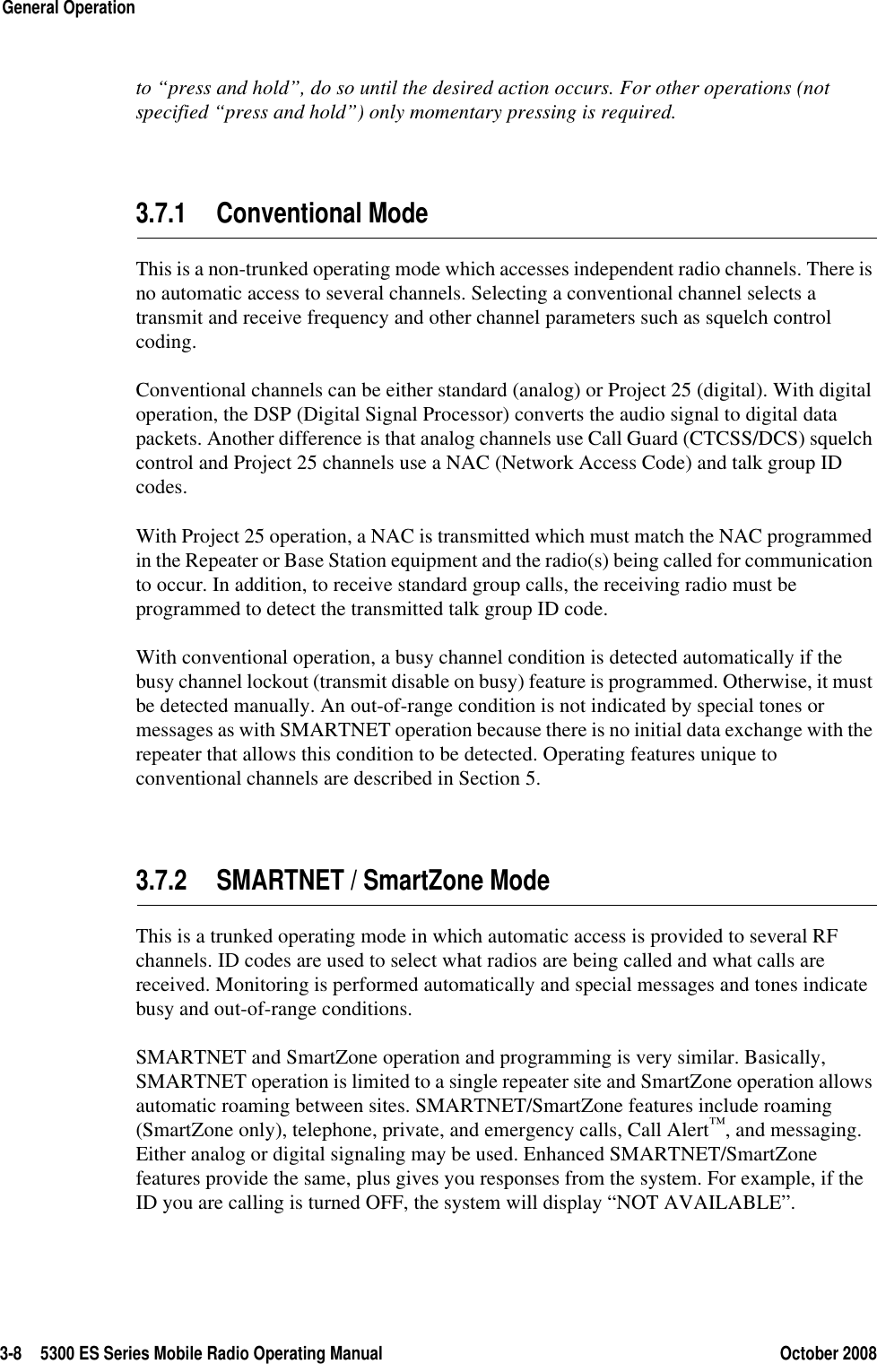
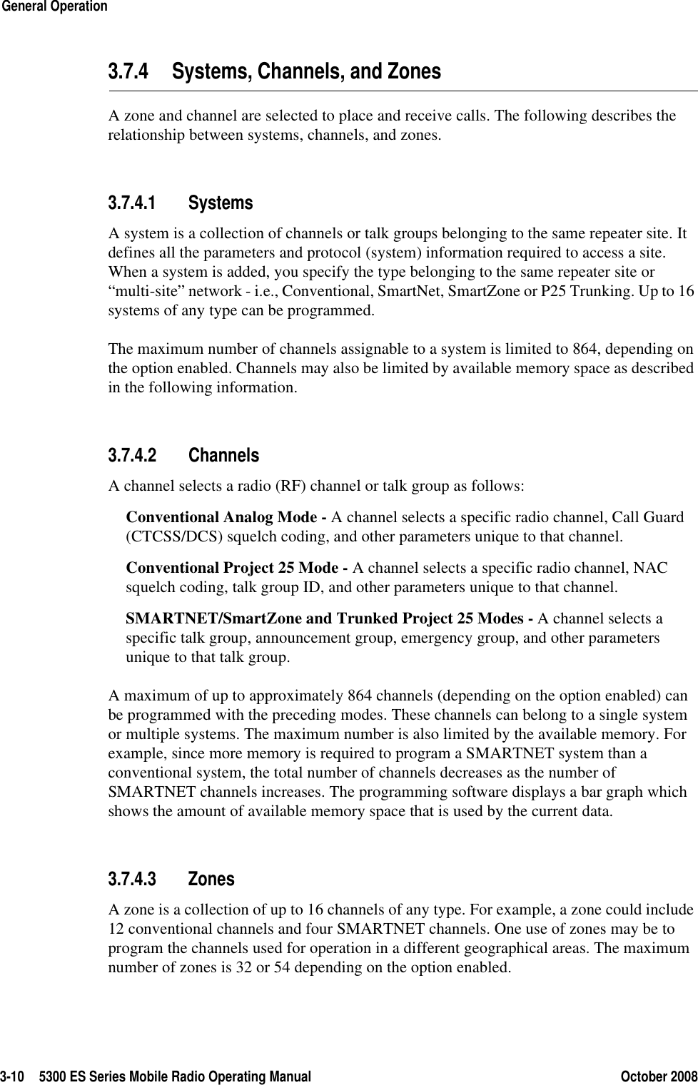
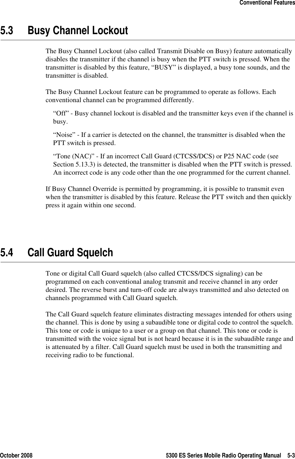
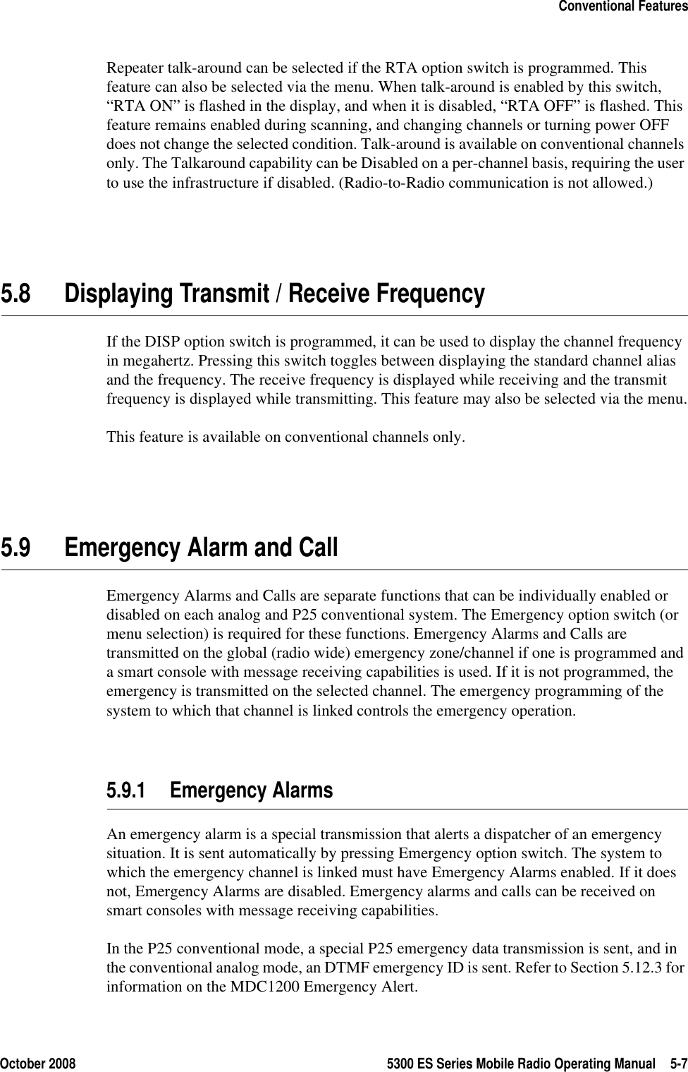
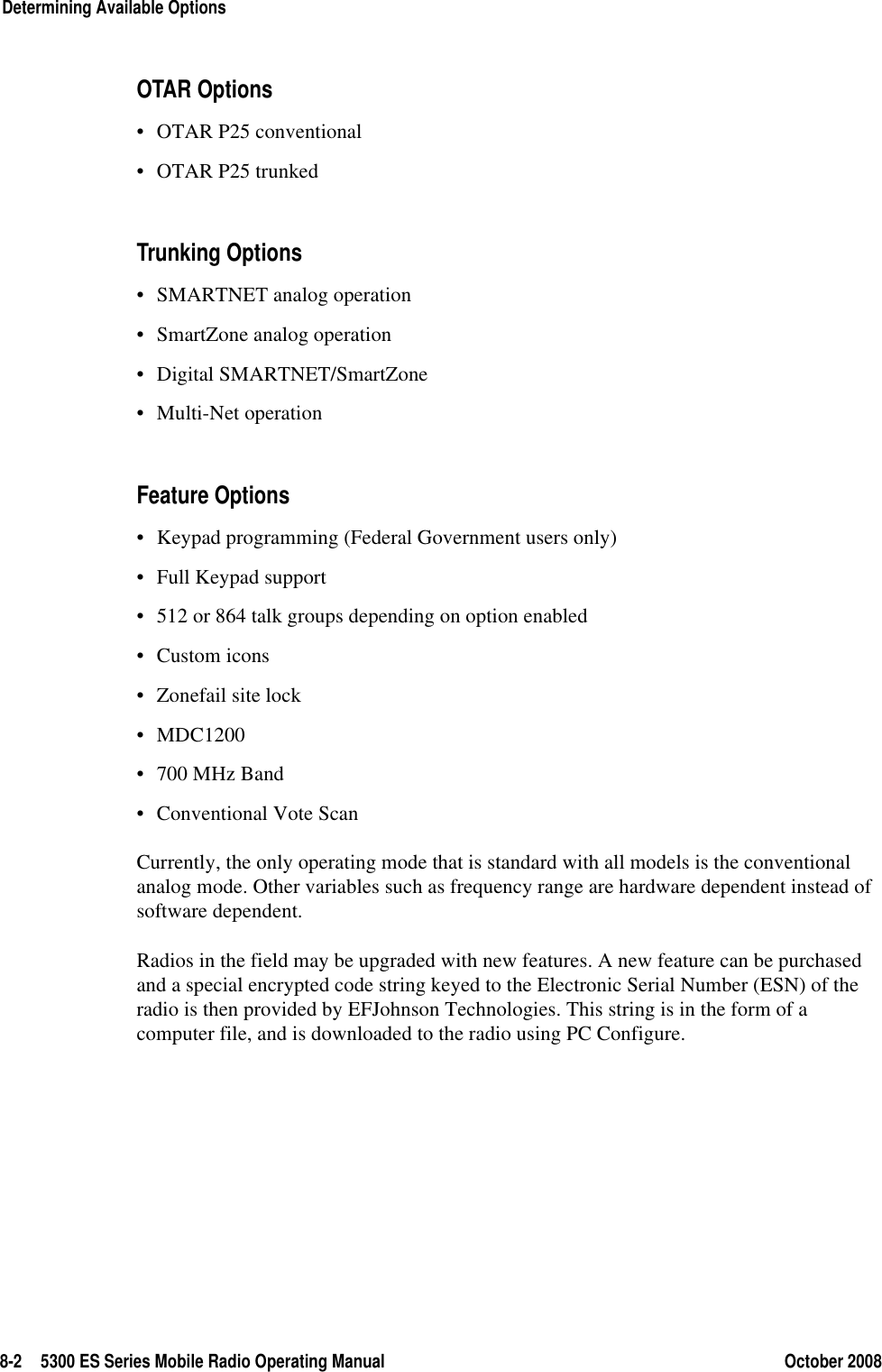
5300 ES Series Mobile RadioOperating ManualProject 25 Conventional and TrunkedAnalog and Digital ConventionalSMARTNET®/SmartZone®Part Number 002-5300-70002October 2008
Copyright © 2007-2008 by EFJohnson TechnologiesThe EFJohnson Technologies logo, PC Configure™, Trunked IP25™, and Call Guard® are trademarks of EFJohnson Technologies. All other company and/or product names used in this manual are trademarks and/or registered trademarks of their respective manufacturers.Information in this manual is subject to change without notice.5300 ES Series Mobile Radio Operating ManualOctober 2008
October 2008 5300 ES Series Mobile Radio Operating Manual iTable of Contents5300 ES Series Mobile Radio Operating ManualSafety Information  xiii1 General 1-1General Features . . . . . . . . . . . . . . . . . . . . . . . . . . . . . . . . . . . . . . . . . . . . . . . . . . . . . . . . . . . . . . . 1-1Conventional Features. . . . . . . . . . . . . . . . . . . . . . . . . . . . . . . . . . . . . . . . . . . . . . . . . . . . . . . . . . . 1-2SMARTNET / SmartZone Features . . . . . . . . . . . . . . . . . . . . . . . . . . . . . . . . . . . . . . . . . . . . . . . . . 1-3Project 25 Trunked Features . . . . . . . . . . . . . . . . . . . . . . . . . . . . . . . . . . . . . . . . . . . . . . . . . . . . . . 1-32 Controls And Display 2-1Front Panel Controls . . . . . . . . . . . . . . . . . . . . . . . . . . . . . . . . . . . . . . . . . . . . . . . . . . . . . . . . . . . . 2-1Rear Panel Connectors . . . . . . . . . . . . . . . . . . . . . . . . . . . . . . . . . . . . . . . . . . . . . . . . . . . . . . . . . . 2-2Display. . . . . . . . . . . . . . . . . . . . . . . . . . . . . . . . . . . . . . . . . . . . . . . . . . . . . . . . . . . . . . . . . . . . . . . . 2-33 General Operation 3-1Turning Power ON and Setting Volume . . . . . . . . . . . . . . . . . . . . . . . . . . . . . . . . . . . . . . . . . . . . . 3-1Standard and Soft Power Down . . . . . . . . . . . . . . . . . . . . . . . . . . . . . . . . . . . . . . . . . . . . . . . . 3-2Setting Volume Level  . . . . . . . . . . . . . . . . . . . . . . . . . . . . . . . . . . . . . . . . . . . . . . . . . . . . . . . . 3-2Power-Up Password. . . . . . . . . . . . . . . . . . . . . . . . . . . . . . . . . . . . . . . . . . . . . . . . . . . . . . . . . . . . . 3-3Backlight Control and Display Viewing Angle Adjust  . . . . . . . . . . . . . . . . . . . . . . . . . . . . . . . . . 3-3Zone / Channel Display and Select. . . . . . . . . . . . . . . . . . . . . . . . . . . . . . . . . . . . . . . . . . . . . . . . . 3-4Zone / Channel Display. . . . . . . . . . . . . . . . . . . . . . . . . . . . . . . . . . . . . . . . . . . . . . . . . . . . . . . 3-4Zone / Channel Select  . . . . . . . . . . . . . . . . . . . . . . . . . . . . . . . . . . . . . . . . . . . . . . . . . . . . . . . 3-5Direct Channel Select . . . . . . . . . . . . . . . . . . . . . . . . . . . . . . . . . . . . . . . . . . . . . . . . . . . . . . . . 3-5Favorite Zone Selection . . . . . . . . . . . . . . . . . . . . . . . . . . . . . . . . . . . . . . . . . . . . . . . . . . . . . . 3-6Setting Squelch Control. . . . . . . . . . . . . . . . . . . . . . . . . . . . . . . . . . . . . . . . . . . . . . . . . . . . . . . . . . 3-7Transmit Disable. . . . . . . . . . . . . . . . . . . . . . . . . . . . . . . . . . . . . . . . . . . . . . . . . . . . . . . . . . . . . . . . 3-7
ii 5300 ES Series Mobile Radio Operating Manual October 2008Table of Contents (continued)Radio Operating Modes. . . . . . . . . . . . . . . . . . . . . . . . . . . . . . . . . . . . . . . . . . . . . . . . . . . . . . . . . . 3-7Conventional Mode. . . . . . . . . . . . . . . . . . . . . . . . . . . . . . . . . . . . . . . . . . . . . . . . . . . . . . . . . . 3-8SMARTNET / SmartZone Mode . . . . . . . . . . . . . . . . . . . . . . . . . . . . . . . . . . . . . . . . . . . . . . . . 3-8P25 Trunked Mode . . . . . . . . . . . . . . . . . . . . . . . . . . . . . . . . . . . . . . . . . . . . . . . . . . . . . . . . . . 3-9Systems, Channels, and Zones . . . . . . . . . . . . . . . . . . . . . . . . . . . . . . . . . . . . . . . . . . . . . . . 3-10Systems. . . . . . . . . . . . . . . . . . . . . . . . . . . . . . . . . . . . . . . . . . . . . . . . . . . . . . . . . . . . . 3-10Channels . . . . . . . . . . . . . . . . . . . . . . . . . . . . . . . . . . . . . . . . . . . . . . . . . . . . . . . . . . . . 3-10Zones. . . . . . . . . . . . . . . . . . . . . . . . . . . . . . . . . . . . . . . . . . . . . . . . . . . . . . . . . . . . . . . 3-10Radio Tune Test Mode . . . . . . . . . . . . . . . . . . . . . . . . . . . . . . . . . . . . . . . . . . . . . . . . . . . . . . . . . . 3-11RF Test Mode . . . . . . . . . . . . . . . . . . . . . . . . . . . . . . . . . . . . . . . . . . . . . . . . . . . . . . . . . . . . . 3-12Control Top and Keypad Test Mode . . . . . . . . . . . . . . . . . . . . . . . . . . . . . . . . . . . . . . . . . . . . 3-124 Radio Wide Features 4-1Option Switches . . . . . . . . . . . . . . . . . . . . . . . . . . . . . . . . . . . . . . . . . . . . . . . . . . . . . . . . . . . . . . . . 4-2Menu Mode . . . . . . . . . . . . . . . . . . . . . . . . . . . . . . . . . . . . . . . . . . . . . . . . . . . . . . . . . . . . . . . . . . . . 4-4Time-Out Timer. . . . . . . . . . . . . . . . . . . . . . . . . . . . . . . . . . . . . . . . . . . . . . . . . . . . . . . . . . . . . . . . . 4-4Home Channel Select. . . . . . . . . . . . . . . . . . . . . . . . . . . . . . . . . . . . . . . . . . . . . . . . . . . . . . . . . . . . 4-5Power Output Select  . . . . . . . . . . . . . . . . . . . . . . . . . . . . . . . . . . . . . . . . . . . . . . . . . . . . . . . . . . . . 4-5Alert Tone Select. . . . . . . . . . . . . . . . . . . . . . . . . . . . . . . . . . . . . . . . . . . . . . . . . . . . . . . . . . . . . . . . 4-5Power Turn-Off Delay. . . . . . . . . . . . . . . . . . . . . . . . . . . . . . . . . . . . . . . . . . . . . . . . . . . . . . . . . . . . 4-6Horn Alert . . . . . . . . . . . . . . . . . . . . . . . . . . . . . . . . . . . . . . . . . . . . . . . . . . . . . . . . . . . . . . . . . . . . . 4-6Microphone Off-Hook Detect. . . . . . . . . . . . . . . . . . . . . . . . . . . . . . . . . . . . . . . . . . . . . . . . . . . . . . 4-7Surveillance Mode . . . . . . . . . . . . . . . . . . . . . . . . . . . . . . . . . . . . . . . . . . . . . . . . . . . . . . . . . . . . . . 4-7Public Address . . . . . . . . . . . . . . . . . . . . . . . . . . . . . . . . . . . . . . . . . . . . . . . . . . . . . . . . . . . . . . . . . 4-8Scanning . . . . . . . . . . . . . . . . . . . . . . . . . . . . . . . . . . . . . . . . . . . . . . . . . . . . . . . . . . . . . . . . . . . . . . 4-8Priority (Standard) Scanning. . . . . . . . . . . . . . . . . . . . . . . . . . . . . . . . . . . . . . . . . . . . . . . . . . . 4-9Radio Wide Scanning . . . . . . . . . . . . . . . . . . . . . . . . . . . . . . . . . . . . . . . . . . . . . . . . . . . . . . . . 4-9Scan Hold Time. . . . . . . . . . . . . . . . . . . . . . . . . . . . . . . . . . . . . . . . . . . . . . . . . . . . . . . . . . . . 4-10Transmitting in the Scan Mode . . . . . . . . . . . . . . . . . . . . . . . . . . . . . . . . . . . . . . . . . . . . . . . . 4-10Nuisance Channel Delete . . . . . . . . . . . . . . . . . . . . . . . . . . . . . . . . . . . . . . . . . . . . . . . . . . . . 4-10Scan Lists . . . . . . . . . . . . . . . . . . . . . . . . . . . . . . . . . . . . . . . . . . . . . . . . . . . . . . . . . . . . . . . . . . . . 4-11Priority Mode Scan Lists   . . . . . . . . . . . . . . . . . . . . . . . . . . . . . . . . . . . . . . . . . . . . . . . . . . . . 4-11Determining Channels in Priority Scan List . . . . . . . . . . . . . . . . . . . . . . . . . . . . . . . . . . 4-11Selecting a Priority Scan List. . . . . . . . . . . . . . . . . . . . . . . . . . . . . . . . . . . . . . . . . . . . . 4-12Editing a Priority Scan List. . . . . . . . . . . . . . . . . . . . . . . . . . . . . . . . . . . . . . . . . . . . . . . 4-12Radio Wide Scan List . . . . . . . . . . . . . . . . . . . . . . . . . . . . . . . . . . . . . . . . . . . . . . . . . . . . . . . 4-13Determining Channels in Radio Wide Scan List . . . . . . . . . . . . . . . . . . . . . . . . . . . . . . 4-13Editing a Radio Wide Scan List. . . . . . . . . . . . . . . . . . . . . . . . . . . . . . . . . . . . . . . . . . . 4-14Global Positioning System (GPS). . . . . . . . . . . . . . . . . . . . . . . . . . . . . . . . . . . . . . . . . . . . . . . . . 4-14Viewing GPS Data  . . . . . . . . . . . . . . . . . . . . . . . . . . . . . . . . . . . . . . . . . . . . . . . . . . . . . . . . . 4-14Sending GPS Data . . . . . . . . . . . . . . . . . . . . . . . . . . . . . . . . . . . . . . . . . . . . . . . . . . . . . . . . . 4-15
October 2008 5300 ES Series Mobile Radio Operating Manual iiiTable of Contents (continued)5 Conventional Features 5-1Monitoring Before Transmitting . . . . . . . . . . . . . . . . . . . . . . . . . . . . . . . . . . . . . . . . . . . . . . . . . . . 5-1Automatic Channel Monitoring . . . . . . . . . . . . . . . . . . . . . . . . . . . . . . . . . . . . . . . . . . . . . . . . . 5-1Manual Channel Monitoring . . . . . . . . . . . . . . . . . . . . . . . . . . . . . . . . . . . . . . . . . . . . . . . . . . . 5-1Monitor Mode . . . . . . . . . . . . . . . . . . . . . . . . . . . . . . . . . . . . . . . . . . . . . . . . . . . . . . . . . . . . . . . . . . 5-2Busy Channel Lockout. . . . . . . . . . . . . . . . . . . . . . . . . . . . . . . . . . . . . . . . . . . . . . . . . . . . . . . . . . . 5-3Call Guard Squelch  . . . . . . . . . . . . . . . . . . . . . . . . . . . . . . . . . . . . . . . . . . . . . . . . . . . . . . . . . . . . . 5-3Call Guard Squelch Enable / Disable . . . . . . . . . . . . . . . . . . . . . . . . . . . . . . . . . . . . . . . . . . . . 5-4Tone Call Guard Squelch . . . . . . . . . . . . . . . . . . . . . . . . . . . . . . . . . . . . . . . . . . . . . . . . . . . . . 5-4Digital Call Guard Squelch . . . . . . . . . . . . . . . . . . . . . . . . . . . . . . . . . . . . . . . . . . . . . . . . . . . . 5-4Selective Squelch Code Select (CTCSS / DSC / NAC) . . . . . . . . . . . . . . . . . . . . . . . . . . . . . . 5-5Penalty Timer . . . . . . . . . . . . . . . . . . . . . . . . . . . . . . . . . . . . . . . . . . . . . . . . . . . . . . . . . . . . . . . . . . 5-6Conversation Timer . . . . . . . . . . . . . . . . . . . . . . . . . . . . . . . . . . . . . . . . . . . . . . . . . . . . . . . . . . . . . 5-6Repeater Talk-Around . . . . . . . . . . . . . . . . . . . . . . . . . . . . . . . . . . . . . . . . . . . . . . . . . . . . . . . . . . . 5-6Displaying Transmit / Receive Frequency . . . . . . . . . . . . . . . . . . . . . . . . . . . . . . . . . . . . . . . . . . . 5-7Emergency Alarm and Call . . . . . . . . . . . . . . . . . . . . . . . . . . . . . . . . . . . . . . . . . . . . . . . . . . . . . . . 5-7Emergency Alarms . . . . . . . . . . . . . . . . . . . . . . . . . . . . . . . . . . . . . . . . . . . . . . . . . . . . . . . . . . 5-7Emergency Group Alert. . . . . . . . . . . . . . . . . . . . . . . . . . . . . . . . . . . . . . . . . . . . . . . . . . . . . . . 5-8Emergency Calls. . . . . . . . . . . . . . . . . . . . . . . . . . . . . . . . . . . . . . . . . . . . . . . . . . . . . . . . . . . . 5-8Emergency Hot Mic. . . . . . . . . . . . . . . . . . . . . . . . . . . . . . . . . . . . . . . . . . . . . . . . . . . . . 5-9Placing an Emergency Call . . . . . . . . . . . . . . . . . . . . . . . . . . . . . . . . . . . . . . . . . . . . . . . 5-9Conventional Mode Scanning . . . . . . . . . . . . . . . . . . . . . . . . . . . . . . . . . . . . . . . . . . . . . . . . . . . . 5-10Selecting a Scan List. . . . . . . . . . . . . . . . . . . . . . . . . . . . . . . . . . . . . . . . . . . . . . . . . . . . . . . . 5-10Conventional Scan List Select Procedure . . . . . . . . . . . . . . . . . . . . . . . . . . . . . . . . . . . 5-10Transmitting in Scan Mode . . . . . . . . . . . . . . . . . . . . . . . . . . . . . . . . . . . . . . . . . . . . . . . . . . . 5-10Priority Channel Sampling. . . . . . . . . . . . . . . . . . . . . . . . . . . . . . . . . . . . . . . . . . . . . . . . . . . . 5-11Changing The Priority Channel . . . . . . . . . . . . . . . . . . . . . . . . . . . . . . . . . . . . . . . . . . . 5-12Standard Conventional Calls. . . . . . . . . . . . . . . . . . . . . . . . . . . . . . . . . . . . . . . . . . . . . . . . . . . . . 5-13Placing a Standard Conventional Call. . . . . . . . . . . . . . . . . . . . . . . . . . . . . . . . . . . . . . . . . . . 5-13Receiving a Standard Conventional Call. . . . . . . . . . . . . . . . . . . . . . . . . . . . . . . . . . . . . . . . . 5-13DTMF / ANI Signaling. . . . . . . . . . . . . . . . . . . . . . . . . . . . . . . . . . . . . . . . . . . . . . . . . . . . . . . . . . . 5-13Single Tone Encoder. . . . . . . . . . . . . . . . . . . . . . . . . . . . . . . . . . . . . . . . . . . . . . . . . . . . . . . . 5-14Five Tone Encoder . . . . . . . . . . . . . . . . . . . . . . . . . . . . . . . . . . . . . . . . . . . . . . . . . . . . . . . . . 5-14MDC1200 Compatibility  . . . . . . . . . . . . . . . . . . . . . . . . . . . . . . . . . . . . . . . . . . . . . . . . . . . . . 5-14Project 25 Mode Features . . . . . . . . . . . . . . . . . . . . . . . . . . . . . . . . . . . . . . . . . . . . . . . . . . . . . . . 5-15Digital Unit ID . . . . . . . . . . . . . . . . . . . . . . . . . . . . . . . . . . . . . . . . . . . . . . . . . . . . . . . . . . . . . 5-15Talk Group ID . . . . . . . . . . . . . . . . . . . . . . . . . . . . . . . . . . . . . . . . . . . . . . . . . . . . . . . . . . . . . 5-15Network Access Code (NAC) . . . . . . . . . . . . . . . . . . . . . . . . . . . . . . . . . . . . . . . . . . . . . . . . . 5-15P25 Group Calls . . . . . . . . . . . . . . . . . . . . . . . . . . . . . . . . . . . . . . . . . . . . . . . . . . . . . . . . . . . 5-15Changing Talk Group Assigned To a Channel. . . . . . . . . . . . . . . . . . . . . . . . . . . . . . . . 5-16P25 Unit Calls . . . . . . . . . . . . . . . . . . . . . . . . . . . . . . . . . . . . . . . . . . . . . . . . . . . . . . . . . . . . . 5-16P25 Conventional Telephone Calls. . . . . . . . . . . . . . . . . . . . . . . . . . . . . . . . . . . . . . . . . . . . . 5-17Access / De-Access Codes. . . . . . . . . . . . . . . . . . . . . . . . . . . . . . . . . . . . . . . . . . . . . . 5-17Placing a Telephone Call. . . . . . . . . . . . . . . . . . . . . . . . . . . . . . . . . . . . . . . . . . . . . . . . 5-17Answering a Telephone Call . . . . . . . . . . . . . . . . . . . . . . . . . . . . . . . . . . . . . . . . . . . . . 5-18Call Alert . . . . . . . . . . . . . . . . . . . . . . . . . . . . . . . . . . . . . . . . . . . . . . . . . . . . . . . . . . . . . . . . . 5-19Call History . . . . . . . . . . . . . . . . . . . . . . . . . . . . . . . . . . . . . . . . . . . . . . . . . . . . . . . . . . . . . . . 5-20
iv 5300 ES Series Mobile Radio Operating Manual October 2008Table of Contents (continued)Messaging. . . . . . . . . . . . . . . . . . . . . . . . . . . . . . . . . . . . . . . . . . . . . . . . . . . . . . . . . . . . . . . . 5-20Status Messaging . . . . . . . . . . . . . . . . . . . . . . . . . . . . . . . . . . . . . . . . . . . . . . . . . . . . . . . . . . 5-20P25 Packet Data. . . . . . . . . . . . . . . . . . . . . . . . . . . . . . . . . . . . . . . . . . . . . . . . . . . . . . . . . . . 5-21Keypad Programming . . . . . . . . . . . . . . . . . . . . . . . . . . . . . . . . . . . . . . . . . . . . . . . . . . . . . . . . . . 5-21Menu Structure . . . . . . . . . . . . . . . . . . . . . . . . . . . . . . . . . . . . . . . . . . . . . . . . . . . . . . . . . . . . 5-22Zone Password. . . . . . . . . . . . . . . . . . . . . . . . . . . . . . . . . . . . . . . . . . . . . . . . . . . . . . . . . . . . 5-23Zone Change Parameter. . . . . . . . . . . . . . . . . . . . . . . . . . . . . . . . . . . . . . . . . . . . . . . . . . . . . 5-23Channel Change Parameter. . . . . . . . . . . . . . . . . . . . . . . . . . . . . . . . . . . . . . . . . . . . . . . . . . 5-24System Parameters. . . . . . . . . . . . . . . . . . . . . . . . . . . . . . . . . . . . . . . . . . . . . . . . . . . . . . . . . 5-24Channel Parameters. . . . . . . . . . . . . . . . . . . . . . . . . . . . . . . . . . . . . . . . . . . . . . . . . . . . . . . . 5-25Text Messaging. . . . . . . . . . . . . . . . . . . . . . . . . . . . . . . . . . . . . . . . . . . . . . . . . . . . . . . . . . . . . . . . 5-27Data Setup for Text Messaging. . . . . . . . . . . . . . . . . . . . . . . . . . . . . . . . . . . . . . . . . . . . . . . . 5-27Receiving a Text Message . . . . . . . . . . . . . . . . . . . . . . . . . . . . . . . . . . . . . . . . . . . . . . . . . . . 5-27Viewing Previously Received Messages. . . . . . . . . . . . . . . . . . . . . . . . . . . . . . . . . . . . . . . . . 5-28Sending Global Positioning System (GPS) Data. . . . . . . . . . . . . . . . . . . . . . . . . . . . . . . . . . . . . 5-28Manually Sending GPS Data  . . . . . . . . . . . . . . . . . . . . . . . . . . . . . . . . . . . . . . . . . . . . . . . . . 5-29Automatically Sending GPS Data . . . . . . . . . . . . . . . . . . . . . . . . . . . . . . . . . . . . . . . . . . . . . . 5-29Sending GPS Data in Response to System Request . . . . . . . . . . . . . . . . . . . . . . . . . . . . . . . 5-296 SMARTNET / SmartZone / P25 Trunked Features 6-1Analog and Digital Operation . . . . . . . . . . . . . . . . . . . . . . . . . . . . . . . . . . . . . . . . . . . . . . . . . . . . . 6-1Viewing Unit ID . . . . . . . . . . . . . . . . . . . . . . . . . . . . . . . . . . . . . . . . . . . . . . . . . . . . . . . . . . . . . . . . . 6-1Radio Info button. . . . . . . . . . . . . . . . . . . . . . . . . . . . . . . . . . . . . . . . . . . . . . . . . . . . . . . . . . . . 6-2Standard Group Calls. . . . . . . . . . . . . . . . . . . . . . . . . . . . . . . . . . . . . . . . . . . . . . . . . . . . . . . . . . . . 6-2Placing a Standard Group Call . . . . . . . . . . . . . . . . . . . . . . . . . . . . . . . . . . . . . . . . . . . . . . . . . 6-2Receiving a Standard Group Call . . . . . . . . . . . . . . . . . . . . . . . . . . . . . . . . . . . . . . . . . . . . . . . 6-3Private (Unit-To-Unit) Calls . . . . . . . . . . . . . . . . . . . . . . . . . . . . . . . . . . . . . . . . . . . . . . . . . . . . . . . 6-4Placing an Enhanced Private Conversation Call. . . . . . . . . . . . . . . . . . . . . . . . . . . . . . . . . . . . 6-4Placing a Standard Private Conversation Call . . . . . . . . . . . . . . . . . . . . . . . . . . . . . . . . . . . . . 6-5Receiving a Private Call (All Types) . . . . . . . . . . . . . . . . . . . . . . . . . . . . . . . . . . . . . . . . . . . . . 6-6Telephone Calls . . . . . . . . . . . . . . . . . . . . . . . . . . . . . . . . . . . . . . . . . . . . . . . . . . . . . . . . . . . . . . . . 6-7Placing a Telephone Call. . . . . . . . . . . . . . . . . . . . . . . . . . . . . . . . . . . . . . . . . . . . . . . . . . . . . . 6-7Receiving A Telephone Call . . . . . . . . . . . . . . . . . . . . . . . . . . . . . . . . . . . . . . . . . . . . . . . . . . . 6-8Call Alert . . . . . . . . . . . . . . . . . . . . . . . . . . . . . . . . . . . . . . . . . . . . . . . . . . . . . . . . . . . . . . . . . . . . . . 6-9Answering a Page. . . . . . . . . . . . . . . . . . . . . . . . . . . . . . . . . . . . . . . . . . . . . . . . . . . . . . . . . . . 6-9Initiating a Page . . . . . . . . . . . . . . . . . . . . . . . . . . . . . . . . . . . . . . . . . . . . . . . . . . . . . . . . . . . 6-10Messaging. . . . . . . . . . . . . . . . . . . . . . . . . . . . . . . . . . . . . . . . . . . . . . . . . . . . . . . . . . . . . . . . . . . . 6-10Sending Status Conditions . . . . . . . . . . . . . . . . . . . . . . . . . . . . . . . . . . . . . . . . . . . . . . . . . . . . . . 6-11Emergency Alarm and Call . . . . . . . . . . . . . . . . . . . . . . . . . . . . . . . . . . . . . . . . . . . . . . . . . . . . . . 6-11Emergency Alarms . . . . . . . . . . . . . . . . . . . . . . . . . . . . . . . . . . . . . . . . . . . . . . . . . . . . . . . . . 6-12Emergency Group Alert. . . . . . . . . . . . . . . . . . . . . . . . . . . . . . . . . . . . . . . . . . . . . . . . . . . . . . 6-12Emergency Calls. . . . . . . . . . . . . . . . . . . . . . . . . . . . . . . . . . . . . . . . . . . . . . . . . . . . . . . . . . . 6-13Emergency Hot Mic. . . . . . . . . . . . . . . . . . . . . . . . . . . . . . . . . . . . . . . . . . . . . . . . . . . . 6-13Placing an Emergency Call . . . . . . . . . . . . . . . . . . . . . . . . . . . . . . . . . . . . . . . . . . . . . . 6-13Failsoft Operation. . . . . . . . . . . . . . . . . . . . . . . . . . . . . . . . . . . . . . . . . . . . . . . . . . . . . . . . . . . . . . 6-14
October 2008 5300 ES Series Mobile Radio Operating Manual vTable of Contents (continued)SMARTNET / SmartZone / P25 Trunked Scanning Features . . . . . . . . . . . . . . . . . . . . . . . . . . . 6-14Priority Talk Group Sampling. . . . . . . . . . . . . . . . . . . . . . . . . . . . . . . . . . . . . . . . . . . . . . . . . . 6-15Scan List Editing and Selection. . . . . . . . . . . . . . . . . . . . . . . . . . . . . . . . . . . . . . . . . . . . . . . . 6-16Dynamic Regrouping . . . . . . . . . . . . . . . . . . . . . . . . . . . . . . . . . . . . . . . . . . . . . . . . . . . . . . . . . . . 6-17SmartZone and P25 Trunking Unique Features. . . . . . . . . . . . . . . . . . . . . . . . . . . . . . . . . . . . . . 6-17Busy Override. . . . . . . . . . . . . . . . . . . . . . . . . . . . . . . . . . . . . . . . . . . . . . . . . . . . . . . . . . . . . 6-18Site Trunking. . . . . . . . . . . . . . . . . . . . . . . . . . . . . . . . . . . . . . . . . . . . . . . . . . . . . . . . . . . . . . 6-18Determining Current Site and Searching for a New Site. . . . . . . . . . . . . . . . . . . . . . . . . . . . . 6-18Locking / Unlocking a Site. . . . . . . . . . . . . . . . . . . . . . . . . . . . . . . . . . . . . . . . . . . . . . . . . . . . 6-19Auto Site Search. . . . . . . . . . . . . . . . . . . . . . . . . . . . . . . . . . . . . . . . . . . . . . . . . . . . . . . . . . . 6-19ZoneFail Site Lock . . . . . . . . . . . . . . . . . . . . . . . . . . . . . . . . . . . . . . . . . . . . . . . . . . . . . . . . . 6-19P25 Wide Area Scan. . . . . . . . . . . . . . . . . . . . . . . . . . . . . . . . . . . . . . . . . . . . . . . . . . . . . . . . 6-20Normal P25 and SmartZone Control Channel Hunt . . . . . . . . . . . . . . . . . . . . . . . . . . . . . . . . 6-20Talkgroup Steering through System Access Permissions. . . . . . . . . . . . . . . . . . . . . . . . . . . . 6-20P25 Wide Area Scan. . . . . . . . . . . . . . . . . . . . . . . . . . . . . . . . . . . . . . . . . . . . . . . . . . . . . . . . 6-20P25 Trunking Unique Features . . . . . . . . . . . . . . . . . . . . . . . . . . . . . . . . . . . . . . . . . . . . . . . . . . . 6-21Radio Configuration  . . . . . . . . . . . . . . . . . . . . . . . . . . . . . . . . . . . . . . . . . . . . . . . . . . . . . . . . 6-22Interface Connection. . . . . . . . . . . . . . . . . . . . . . . . . . . . . . . . . . . . . . . . . . . . . . . . . . . . . . . . 6-23Context Activation. . . . . . . . . . . . . . . . . . . . . . . . . . . . . . . . . . . . . . . . . . . . . . . . . . . . . . . . . . 6-23PPP Link Establishment . . . . . . . . . . . . . . . . . . . . . . . . . . . . . . . . . . . . . . . . . . . . . . . . . . . . . 6-23Connection and Testing. . . . . . . . . . . . . . . . . . . . . . . . . . . . . . . . . . . . . . . . . . . . . . . . . . . . . . 6-38Connection  . . . . . . . . . . . . . . . . . . . . . . . . . . . . . . . . . . . . . . . . . . . . . . . . . . . . . . . . . . 6-38PPP Link Test . . . . . . . . . . . . . . . . . . . . . . . . . . . . . . . . . . . . . . . . . . . . . . . . . . . . . . . . 6-397 Miscellaneous 7-1Supervisory Tones . . . . . . . . . . . . . . . . . . . . . . . . . . . . . . . . . . . . . . . . . . . . . . . . . . . . . . . . . . . . . . 7-1Error Messages. . . . . . . . . . . . . . . . . . . . . . . . . . . . . . . . . . . . . . . . . . . . . . . . . . . . . . . . . . . . . . . . . 7-3System Operator Programming . . . . . . . . . . . . . . . . . . . . . . . . . . . . . . . . . . . . . . . . . . . . . . . . . . . 7-6Speaking Into Microphone. . . . . . . . . . . . . . . . . . . . . . . . . . . . . . . . . . . . . . . . . . . . . . . . . . . . . . . . 7-6Operation At Extended Range. . . . . . . . . . . . . . . . . . . . . . . . . . . . . . . . . . . . . . . . . . . . . . . . . . . . . 7-7Preventing Battery Discharge. . . . . . . . . . . . . . . . . . . . . . . . . . . . . . . . . . . . . . . . . . . . . . . . . . . . . 7-7Cleaning the Control Head  . . . . . . . . . . . . . . . . . . . . . . . . . . . . . . . . . . . . . . . . . . . . . . . . . . . . . . . 7-7Licensing. . . . . . . . . . . . . . . . . . . . . . . . . . . . . . . . . . . . . . . . . . . . . . . . . . . . . . . . . . . . . . . . . . . . . . 7-8Radio Service . . . . . . . . . . . . . . . . . . . . . . . . . . . . . . . . . . . . . . . . . . . . . . . . . . . . . . . . . . . . . . . . . . 7-88 Determining Available Options 8-19 Password Description 9-1Programming Passwords  . . . . . . . . . . . . . . . . . . . . . . . . . . . . . . . . . . . . . . . . . . . . . . . . . . . . . . . . 9-1Lost Passwords. . . . . . . . . . . . . . . . . . . . . . . . . . . . . . . . . . . . . . . . . . . . . . . . . . . . . . . . . . . . . 9-2
vi 5300 ES Series Mobile Radio Operating Manual October 2008Table of Contents (continued)Changing Passwords . . . . . . . . . . . . . . . . . . . . . . . . . . . . . . . . . . . . . . . . . . . . . . . . . . . . . . . . 9-2Password Entry Procedure. . . . . . . . . . . . . . . . . . . . . . . . . . . . . . . . . . . . . . . . . . . . . . . . . . . . 9-2Password Description . . . . . . . . . . . . . . . . . . . . . . . . . . . . . . . . . . . . . . . . . . . . . . . . . . . . . . . . . . . 9-2User (Power-On) Passwords . . . . . . . . . . . . . . . . . . . . . . . . . . . . . . . . . . . . . . . . . . . . . . . . . . 9-2Download/Upload Passwords. . . . . . . . . . . . . . . . . . . . . . . . . . . . . . . . . . . . . . . . . . . . . . . . . . 9-3Master Password . . . . . . . . . . . . . . . . . . . . . . . . . . . . . . . . . . . . . . . . . . . . . . . . . . . . . . . . . . . 9-3Zone Password  . . . . . . . . . . . . . . . . . . . . . . . . . . . . . . . . . . . . . . . . . . . . . . . . . . . . . . . . . . . . . . . . 9-310 Secure Communication (Encryption) 10-1Encryption Algorithms. . . . . . . . . . . . . . . . . . . . . . . . . . . . . . . . . . . . . . . . . . . . . . . . . . . . . . . . . . 10-1SecureNet™ . . . . . . . . . . . . . . . . . . . . . . . . . . . . . . . . . . . . . . . . . . . . . . . . . . . . . . . . . . . . . . 10-1AES (Advanced Encryption Standard) . . . . . . . . . . . . . . . . . . . . . . . . . . . . . . . . . . . . . . . . . . 10-2Encryption Available With Various Channel Types . . . . . . . . . . . . . . . . . . . . . . . . . . . . . . . . . 10-2FIPS and Non-FIPS Modes. . . . . . . . . . . . . . . . . . . . . . . . . . . . . . . . . . . . . . . . . . . . . . . . . . . 10-2Encryption Keys. . . . . . . . . . . . . . . . . . . . . . . . . . . . . . . . . . . . . . . . . . . . . . . . . . . . . . . . . . . . . . . 10-2Key and Algorithm IDs . . . . . . . . . . . . . . . . . . . . . . . . . . . . . . . . . . . . . . . . . . . . . . . . . . . . . . 10-3PID / SLN Key Management Modes. . . . . . . . . . . . . . . . . . . . . . . . . . . . . . . . . . . . . . . . . . . . 10-3Maintaining Keys in Memory. . . . . . . . . . . . . . . . . . . . . . . . . . . . . . . . . . . . . . . . . . . . . . . . . . 10-4Encryption Key Select. . . . . . . . . . . . . . . . . . . . . . . . . . . . . . . . . . . . . . . . . . . . . . . . . . . . . . . 10-4Encryption Key Erase . . . . . . . . . . . . . . . . . . . . . . . . . . . . . . . . . . . . . . . . . . . . . . . . . . . . . . . 10-5Encryption Icon Operation. . . . . . . . . . . . . . . . . . . . . . . . . . . . . . . . . . . . . . . . . . . . . . . . . . . . 10-5Clear / Secure Strapping . . . . . . . . . . . . . . . . . . . . . . . . . . . . . . . . . . . . . . . . . . . . . . . . . . . . . . . . 10-5Transmit Mode Options. . . . . . . . . . . . . . . . . . . . . . . . . . . . . . . . . . . . . . . . . . . . . . . . . . . . . . 10-5Analog Receive Mode Options . . . . . . . . . . . . . . . . . . . . . . . . . . . . . . . . . . . . . . . . . . . . . . . . 10-6Talk Group Encryption Override . . . . . . . . . . . . . . . . . . . . . . . . . . . . . . . . . . . . . . . . . . . . . . . 10-7Over-The-Air Rekeying (OTAR) . . . . . . . . . . . . . . . . . . . . . . . . . . . . . . . . . . . . . . . . . . . . . . . . . . . 10-7Encryption Key Types . . . . . . . . . . . . . . . . . . . . . . . . . . . . . . . . . . . . . . . . . . . . . . . . . . . . . . . 10-7Keysets. . . . . . . . . . . . . . . . . . . . . . . . . . . . . . . . . . . . . . . . . . . . . . . . . . . . . . . . . . . . . . . . . . 10-8Key Management Facility . . . . . . . . . . . . . . . . . . . . . . . . . . . . . . . . . . . . . . . . . . . . . . . . . . . . 10-9Message Number Period (MNP). . . . . . . . . . . . . . . . . . . . . . . . . . . . . . . . . . . . . . . . . . . . . . . 10-9Definitions. . . . . . . . . . . . . . . . . . . . . . . . . . . . . . . . . . . . . . . . . . . . . . . . . . . . . . . . . . . . . . . 10-10Radio Setup For Encryption . . . . . . . . . . . . . . . . . . . . . . . . . . . . . . . . . . . . . . . . . . . . . . . . . . . . 10-12Motorola Third Party RNC Registration. . . . . . . . . . . . . . . . . . . . . . . . . . . . . . . . . . . . 10-13Programming By Keyloader. . . . . . . . . . . . . . . . . . . . . . . . . . . . . . . . . . . . . . . . . . . . . 10-13Radio OTAR Capabilities . . . . . . . . . . . . . . . . . . . . . . . . . . . . . . . . . . . . . . . . . . . . . . . . . . . . . . . 10-14OTAR Option Switches . . . . . . . . . . . . . . . . . . . . . . . . . . . . . . . . . . . . . . . . . . . . . . . . . . . . . 10-15P25 Trunking Icons. . . . . . . . . . . . . . . . . . . . . . . . . . . . . . . . . . . . . . . . . . . . . . . . . . . . . . . . 10-16Over the Air Programming. . . . . . . . . . . . . . . . . . . . . . . . . . . . . . . . . . . . . . . . . . . . . . . . . . . . . . 10-17Radio Set Up  . . . . . . . . . . . . . . . . . . . . . . . . . . . . . . . . . . . . . . . . . . . . . . . . . . . . . . . . . . . . 10-17OTAP Transfer Times . . . . . . . . . . . . . . . . . . . . . . . . . . . . . . . . . . . . . . . . . . . . . . . . . . . . . . 10-1811 Service Information 11-1Product Warranty . . . . . . . . . . . . . . . . . . . . . . . . . . . . . . . . . . . . . . . . . . . . . . . . . . . . . . . . . . . . . . 11-1Online Registration  . . . . . . . . . . . . . . . . . . . . . . . . . . . . . . . . . . . . . . . . . . . . . . . . . . . . . . . . . . . . 11-1
October 2008 5300 ES Series Mobile Radio Operating Manual viiTable of Contents (continued)Telephone Technical Support . . . . . . . . . . . . . . . . . . . . . . . . . . . . . . . . . . . . . . . . . . . . . . . . . . . . 11-2Factory Customer Service. . . . . . . . . . . . . . . . . . . . . . . . . . . . . . . . . . . . . . . . . . . . . . . . . . . . . . . 11-2Returns for Repairs . . . . . . . . . . . . . . . . . . . . . . . . . . . . . . . . . . . . . . . . . . . . . . . . . . . . . . . . . . . . 11-3Replacement Parts. . . . . . . . . . . . . . . . . . . . . . . . . . . . . . . . . . . . . . . . . . . . . . . . . . . . . . . . . . . . . 11-4Internet Home Page . . . . . . . . . . . . . . . . . . . . . . . . . . . . . . . . . . . . . . . . . . . . . . . . . . . . . . . . . . . . 11-4
viii 5300 ES Series Mobile Radio Operating Manual October 2008Table of Contents (continued)
October 2008 5300 ES Series Mobile Radio Operating Manual ixList of FiguresFigure Page2.1  Front Panel Controls . . . . . . . . . . . . . . . . . . . . . . . . . . . . . . . . . . . . . . . . . . . . . . . . . . . . 2-12.2  Rear Panel Connectors . . . . . . . . . . . . . . . . . . . . . . . . . . . . . . . . . . . . . . . . . . . . . . . . . . 2-22.3  Front Panel Display . . . . . . . . . . . . . . . . . . . . . . . . . . . . . . . . . . . . . . . . . . . . . . . . . . . . . 2-35.1  5300 ES Keypad Programming Menu Flowchart  . . . . . . . . . . . . . . . . . . . . . . . . . . . . . 5-236.1  Network Connection Screen . . . . . . . . . . . . . . . . . . . . . . . . . . . . . . . . . . . . . . . . . . . . . 6-246.2  New Connection Wizard Screen . . . . . . . . . . . . . . . . . . . . . . . . . . . . . . . . . . . . . . . . . . 6-256.3  Network Connection Type Screen  . . . . . . . . . . . . . . . . . . . . . . . . . . . . . . . . . . . . . . . . 6-256.4  Advanced Connection Options Screen . . . . . . . . . . . . . . . . . . . . . . . . . . . . . . . . . . . . . 6-266.5  Host or Guest Screen  . . . . . . . . . . . . . . . . . . . . . . . . . . . . . . . . . . . . . . . . . . . . . . . . . . 6-276.6  Connection Name Screen . . . . . . . . . . . . . . . . . . . . . . . . . . . . . . . . . . . . . . . . . . . . . . . 6-276.7  Select a Device Screen . . . . . . . . . . . . . . . . . . . . . . . . . . . . . . . . . . . . . . . . . . . . . . . . . 6-286.8  Connection Availability  . . . . . . . . . . . . . . . . . . . . . . . . . . . . . . . . . . . . . . . . . . . . . . . . . 6-296.9  Completing New Connection Wizard Screen  . . . . . . . . . . . . . . . . . . . . . . . . . . . . . . . . 6-296.10  Connect Radio Screen  . . . . . . . . . . . . . . . . . . . . . . . . . . . . . . . . . . . . . . . . . . . . . . . . . 6-306.11  Radio Properties Screen: General Tab . . . . . . . . . . . . . . . . . . . . . . . . . . . . . . . . . . . . . 6-316.12  Modem Configuration Screen . . . . . . . . . . . . . . . . . . . . . . . . . . . . . . . . . . . . . . . . . . . . 6-326.13  Radio Properties Screen: Options Tab . . . . . . . . . . . . . . . . . . . . . . . . . . . . . . . . . . . . . 6-336.14  Radio Properties Screen: Networking Tab  . . . . . . . . . . . . . . . . . . . . . . . . . . . . . . . . . . 6-346.15  Internet Protocol (TCP/IP) Properties Screen . . . . . . . . . . . . . . . . . . . . . . . . . . . . . . . . 6-356.16  Advanced TCP/IP Settings Screen . . . . . . . . . . . . . . . . . . . . . . . . . . . . . . . . . . . . . . . . 6-366.17  Internet Protocol (TCP/IP) Properties Screen . . . . . . . . . . . . . . . . . . . . . . . . . . . . . . . . 6-376.18  Radio Properties Screen: Networking Tab  . . . . . . . . . . . . . . . . . . . . . . . . . . . . . . . . . . 6-386.19  Radio Connection Window  . . . . . . . . . . . . . . . . . . . . . . . . . . . . . . . . . . . . . . . . . . . . . . 6-396.20  Command Prompt Screen: Sending “Ping” . . . . . . . . . . . . . . . . . . . . . . . . . . . . . . . . . . 6-396.21  Command Prompt Screen: Replies to Successful “Ping”  . . . . . . . . . . . . . . . . . . . . . . . 6-4010.1  Key Selection Example . . . . . . . . . . . . . . . . . . . . . . . . . . . . . . . . . . . . . . . . . . . . . . . . . 10-3
x 5300 ES Series Mobile Radio Operating Manual October 2008List of Figures (continued)Figure Page
October 2008 5300 ES Series Mobile Radio Operating Manual xiList of TablesTable Page3.1 Initial Messages  . . . . . . . . . . . . . . . . . . . . . . . . . . . . . . . . . . . . . . . . . . . . . . . . . . . . . . 3-113.2 RF Test Mode Frequencies (MHz)  . . . . . . . . . . . . . . . . . . . . . . . . . . . . . . . . . . . . . . . . 3-123.3 RF Test Mode Environments. . . . . . . . . . . . . . . . . . . . . . . . . . . . . . . . . . . . . . . . . . . . . 3-123.4 Control Top and Keypad Test Mode Display Messages . . . . . . . . . . . . . . . . . . . . . . . . 3-134.1 Programmable Option Button and Menu Mode Functions. . . . . . . . . . . . . . . . . . . . . . . . 4-2
xii 5300 ES Series Mobile Radio Operating Manual October 2008List of Tables (continued)Table Page
October 2008 5300 ES Series Mobile Radio Operating Manual xiiiSection0Safety InformationRF Energy Exposure Awareness and Control Information, and Operational Instructions for FCC Occupational Use RequirementsBefore using your mobile two-way radio, read this important RF energy awareness and control information and operational instructions to ensure compliance with the FCC’s RF exposure guidelines.Note This radio is intended for use in occupational/controlled conditions, where users have full knowledge of their exposure and can exercise control over their exposure to meet FCC limits. This radio device is NOT authorized for general population, consumer, or any other use. This two-way radio uses electromagnetic energy in the radio frequency (RF) spectrum to provide communications between two or more users over a distance. It uses radio frequency (RF) energy or radio waves to send and receive calls. RF energy is one form of electromagnetic energy. Other forms include, but are not limited to, electric power, sunlight and x-rays. RF energy, however, should not be confused with these other forms of electromagnetic energy, which when used improperly can cause biological damage. Very high levels of x-rays, for example, can damage tissues and genetic material. Experts in science, engineering, medicine, health and industry work with organizations to develop standards for exposure to RF energy. These standards provide recommended levels of RF exposure for both workers and the general public. These recommended RF exposure levels include substantial margins of protection. All two-way radios marketed in North America are designed, manufactured and tested to ensure they meet government established RF exposure levels. In addition, manufacturers also recommend specific operating instructions to users of two-way radios. These instructions are important because they inform users about RF energy exposure and provide simple procedures on how to control it. Please refer to the following web sites for more information on what RF energy exposure is and how to control your exposure to assure compliance with established RF exposure limits.•http://www.fcc.gov/oet/rfsafety/rf-faqs.html• http://www.osha.gov/SLTC/radiofrequencyradiation/index.html Federal Communications Commission RegulationsThe FCC rules require manufacturers to comply with the FCC RF energy exposure limits for mobile two-way radios before they can be marketed in the U.S. When two-way radios are used as a consequence of employment, the FCC requires users to be fully aware of and able to control their exposure to meet occupational requirements. Exposure awareness can be facilitated by the use of a label directing users to specific user awareness information.
xiv 5300 ES Series Mobile Radio Operating Manual October 2008Safety InformationYour EFJohnson Technologies two-way radio has a RF exposure product label. Also, your EFJohnson Technologies user manual, or product manual, or separate safety booklet includes information and operating instructions required to control your RF exposure and to satisfy compliance requirements.Compliance with RF Exposure StandardsYour EFJohnson Technologies two-way radio is designed and tested to comply with a number of national and international standards and guidelines (listed below) regarding human exposure to radio frequency electromagnetic energy. This radio complies with the IEEE and ICNIRP exposure limits for occupational/controlled RF exposure environment at duty factors of up to 50% talk and 100% listen and is authorized by the FCC for occupational use. In terms of measuring RF energy for compliance with the FCC exposure guidelines, your radio antenna radiates measurable RF energy only while it is transmitting (during talking), not when it is receiving (listening) or in standby mode.Your EFJohnson Technologies two-way radio complies with the following RF energy exposure standards and guidelines:• United States Federal Communications Commission, Code of Federal Regulations; 47 CFR §§ 2 sub-part J.• American National Standards Institute (ANSI) / Institute of Electrical and Electronic Engineers (IEEE) C95. 1-1992.• Institute of Electrical and Electronic Engineers (IEEE) C95.1-1999 Edition.RF Exposure Compliance and Control Guidelines and Operating InstructionsTo control exposure to yourself and others and ensure compliance with the occupational/controlled environment exposure limits always adhere to the following procedures.Guidelines• User awareness instructions should accompany device when transferred to other users.• Do not use this device if the operational requirements described herein are not met.InstructionsTransmit no more than the rated duty factor of 50% of the time. To transmit (talk), push the Push-To-Talk (PTT) button. To receive calls, release the PTT button. Transmitting 50% of the time, or less, is important because this radio generates measurable RF energy exposure only when transmitting (in terms of measuring for standards compliance).
October 2008 5300 ES Series Mobile Radio Operating Manual xvSafety InformationTransmit only when people outside the vehicle are at least the recommended minimum lateral distance away, as shown in Table 1, from a properly installed according to installation instructions, externally-mounted antenna.Note The following table lists the recommended minimum lateral distance for bystanders in an uncontrolled environment from transmitting types of antennas (i.e., monopoles over a ground plane, or dipoles) at several different ranges of rated radio power for mobile radios installed in a vehicle.Mobile Antennas• Install antennas at the center of the roof or the center of the trunk deck taking into account the bystander exposure conditions of backseat passengers and the recommended minimum lateral distances in Table 1. These mobile antenna installation guidelines are limited to metal body motor vehicles or vehicles with appropriate ground planes. The antenna installation should additionally be in accordance with:- The requirements of the antenna manufacturer/supplier.- Instructions in the Radio Installation Manual, including minimum antenna cable lengths.- The installation manual should provide specific information of how to install the antennas to facilitate recommended operating distances to all potentially exposed persons.• Use only EFJohnson Technologies-approved supplied antenna or EFJohnson Technologies-approved replacement antenna. Unauthorized antennas, modifications, or attachments could damage the radio and may violate FCC regulations. Antennas tested with EFJohnson Technologies radios are listed below.Rated Power of Vehicle-Installed Two-Way RadioRecommended Minimum Lateral Distance From Transmitting AntennaUp to 50 watts 1.0 meter50-110 watts 1.5 meterFrequency Whip Model No. Base Model No.136-144 MHz ASPJ1415 KM220144-152 MHz ASPA1415 KM220152-162 MHz ASPB1415 KM220162-174 MHz ASPC1415 KM220400-430 MHz ASPE1615 KM220430-470 MHz ASPD1615 KM220470--512 MHz ASPF1615 KM220806-869 MHz ASPA1855 KM220890-960 MHz ASPG1865 KM220
xvi 5300 ES Series Mobile Radio Operating Manual October 2008Safety InformationApproved Accessories This radio has been tested and meets the FCC RF exposure guidelines when used with the EFJohnson Technologies accessories supplied or designated for this product. Use of other accessories may not ensure compliance with the FCC’s RF exposure guidelines, and may violate FCC regulations.For a list of EFJohnson Technologies approved accessories, refer to the radio service manual or contact EFJohnson Technologies as follows.Contact InformationFor additional information on exposure requirements or other information, contact EFJohnson Technologies at the following address or telephone number:Customer Service DepartmentEFJohnson Technologies8050 Jetstar # 175Irving, TX 75063Telephone Toll Free: (800) 328-3911This device complies with Part 15 of the FCC rules. Operation is subject to the condition that this device does not cause harmful interference. In addition, changes or modification to this equipment not expressly approved by EFJohnson Technologies could void the users authority to operate this equipment (FCC Rules, 47CFR Part15.19).Note This equipment has been tested and found to comply with the limits for a Class A digital device, pursuant to part 15 of the FCC Rules. These limits are designed to provide reasonable protection against harmful interference when the equipment is operated in a commercial environment. This equipment generates, uses, and can radiate radio frequency energy and, if not installed and used in accordance with the instruction manual, may cause harmful interference to radio communications. Operation of this equipment in a residential area is likely to cause harmful interference in which case the user will be required to correct the interference at his own expense.
October 2008 5300 ES Series Mobile Radio Operating Manual 1-1SECTION1Section 1GeneralThe availability of many of the following features is controlled by field programming and by what options were ordered. For example, encryption and some operating modes are optional. See the EFJohnson Technologies product description and Section 8 for further details.1.1 General FeaturesGeneral features of the radio are:• The following operating modes are programmable:- Conventional analog and APCO P25- Trunked SMARTNET®/SmartZone® and APCO P25• AES 256-bit FIPS 140-2 approved encryption available on P25/digital channels.• DES 64-bit encryption available on analog channels, DES-OFB FIPS 140-2 approved encryption available on digital channels (see Section 10).• Up to 32 zones with 16 channels each are standard (up to 864 channels total depending on option enabled).• Large liquid crystal display (LCD) with backlight• Six programmable option switches• Horn alert• External public address• Programmable power-off delay• Programmable soft power-down
1-2 5300 ES Series Mobile Radio Operating Manual October 2008General• Each option button programmable with a different function for each operating mode (Conventional, SMARTNET/SmartZone, Trunked P25) • Emergency calls for high priority system access• Priority (standard) and Radio Wide scan modes with user programmable scan lists• User selectable high and low power output• Surveillance mode• Time-out timer• Power up password to prevent unauthorized use.• Programmable and user adjustable tone volume• Programmable minimum volume level• Operates on both wide and narrow band channels1.2 Conventional FeaturesThe following Conventional features are available:• Up to 512 or 864 channels or talk groups programmable depending on option enabled• Repeater talk-around• Carrier or Call Guard® (CTCSS/DCS) controlled squelch on analog channels, NAC and talk group IDs on P25 channels• Normal/selective squelch selectable by option switch• Monitor mode selectable by option switch• Time out penalty and conversation timers• Dual priority channel sampling when scanning (analog and digital channels)• Busy channel lockout (transmit disable on busy)• Unit calls on P25 channels• Telephone calls on P25 channels with overdial• Emergency alarms and calls to alert a dispatcher of an emergency condition (analog emergency available).• Automatic Number Identification (ANI) on analog channels • MDC 1200 ANI and Emergency Alert support• Call Alert™ on P25 channels (send and receive pages)
October 2008 5300 ES Series Mobile Radio Operating Manual 1-3General• Predefined messages (up to 16) can be sent to a dispatcher (P25 mode only)• Predefined status conditions (up to eight) can be sent to a dispatcher (P25 mode only)• OTAR (Over-The-Air-Rekeying) compatible (P25 channels only).• Keypad programming with password access (Federal Government users only• Text message receive (APCO P25 digital)1.3 SMARTNET / SmartZone FeaturesThe following SMARTNET/SmartZone features are available:• Up to 512 or 864 talk groups programmable (channels select talk groups) depending on option enabled• Group, Enhanced Private Conversation™, standard Private Conversation, and Telephone calls• Emergency alarms to alert a dispatcher of emergency conditions• Emergency calls for high priority system access• Failsoft operation on a predefined conventional channel if trunked system fails• Priority group calls detected while listening to other group calls when scanning• Call Alert™ (send and receive pages)• Predefined messages (up to 16) can be sent to a dispatcher• Predefined status conditions (up to eight) can be sent to a dispatcher• Dynamic regrouping (dispatcher can automatically gather users on a channel to receive a message)• Roaming (SmartZone only)• Announcement Group1.4 Project 25 Trunked FeaturesThe following P25 features are available:• Up to 864 talk groups programmable (channels select talk groups) depending on option enabled
1-4 5300 ES Series Mobile Radio Operating Manual October 2008General• Group and Unit Calls• Telephone calls with overdialing• Emergency alarms to alert a dispatcher of emergency conditions• Emergency calls for high priority system access• Failsoft operation on a predefined conventional channel if trunked system fails• Priority group calls detected while listening to other group calls when scanning• Call Alert™ (send and receive pages)• Predefined status conditions (up to eight) can be sent to a dispatcher• Dynamic regrouping (dispatcher can automatically gather users on a channel to receive a message)•Roaming• Announcement Group
October 2008 5300 ES Series Mobile Radio Operating Manual 2-1SECTION2Section 2Controls And Display2.1 Front Panel ControlsFigure 2.1 shows the controls for the 5300 ES Mobile radio.Figure 2.1 Front Panel ControlsON-OFF /Volume - Pressing this control turns power ON and OFF (soft power down can be programmed as in Section 3.1.1), and rotating it sets the volume level.Select Switch - This switch can be pressed or rotated. An optional beep can be programmed to sound when it is pressed. Selects zones/channels and is also used for other functions such as selecting names from a call list. When selecting zones/channels, a bar above the zone or channel display (see Figure 2.3) indicates which is being changed. This bar is switched between displays by pressing this switch, and zone and channels are selected by rotating it (see Section 3.4.2). If this switch is pressed and held, the radio enters Menu Mode.Multi-functionProgrammable Buttons DisplayON-OFF/Volume Select Switch SpeakerIndicatorMicrophoneConnection
2-2 5300 ES Series Mobile Radio Operating Manual October 2008Controls And DisplayMulti-function Indicator - This is a two-color LED that indicates the following:Red (constant) - Transmitter keyed (PTT switch pressed).Green (constant) - Busy condition (carrier detected in receive mode).Note This indicator is disabled when the Surveillance mode is programmed (see Section 4.10).Option Switches - Each of the six options switches on the front panel (including the one located to the left of the display) can be programmed by your system operator to control some function. The switch functions can be different for each operating mode (conventional, SMARTNET/SmartZone, and Project 25 Trunked). Therefore, up to 18 functions can be controlled by these switches. Refer to Section 4.1 for more information on option switch functions.Speaker - An internal 16-ohm, 5-watt speaker is located behind the grille. An optional 4-ohm, 12-watt external speaker may be used if desired. The internal speaker is disabled when an external speaker is used.2.2 Rear Panel ConnectorsFigure 2.2 shows the Rear Panel Connectors.Figure 2.2 Rear Panel ConnectorsDC Power - Connection point for the nominal 12-volt, negative ground power source (see Figure 2.2).Antenna - Type N for connecting the antenna.Accessory - Black connector for connecting optional accessories such as an external speaker (4-ohm, 12-watt), horn alert, and ignition sense line.Data (Not Shown) - An optional female DB9 jack for connecting external data equipment when the P25 Packet Data feature is used (see Section 5.13.11).AccessoryAntenna DC Power
October 2008 5300 ES Series Mobile Radio Operating Manual 2-3Controls And DisplaySiren Control (Not Shown) - An optional yellow/orange connector similar to the accessory jack for connecting the optional siren controller.2.3 DisplayFigure 2.3 shows the front panel display.Figure 2.3 Front Panel DisplayAlphanumeric Display - This ten-character area of the display indicates the alias (unique identification) for the selected zone, channel or combined aliases, depending on which select mode is active. It may also indicate such things as the channel frequency, ID numbers, and status and error messages.Zone Number - Indicates the currently selected zone from 1 up to 54, depending on the options installed. A zone is a collection of channels that can be any combination of the conventional, P25 Trunked, and SMARTNET/SmartZone types.Channel Number - Indicates the currently selected channel (conventional) or talk group (other modes).Note The zone/channel numeric display and the zone/channel select bars in all supported protocols and display operating modes can be inhibited.Status Display - These two characters indicate the following status information:This symbol in the left position indicates that the displayed channel is in the scan list (scanned normally).With R in the left Status position, this symbol indicates Radio Wide Scan (see Section 4.12.2.)MON10 - Character Alphanumeric Display ZoneNumber StatusDisplay ChannelNumberScan EditModeTelephone/SpecialCall Channel Encryption Channel SelectIndicatorZone SelectIndicator
2-4 5300 ES Series Mobile Radio Operating Manual October 2008Controls And DisplayA “P” in the left position indicates that the selected conventional channel is a priority channel (first priority with dual priority).A “2” in the left position indicates that the selected conventional channel is a second priority channel. This rotating clock-like symbol in the right position indicates that scanning is enabled. When beneath Button 1, indicates that the scan list edit or keypad programming mode is selected (see Section 4.13 or Section 5.14). This symbol is also used for P25 Trunking OTAR.When beneath Button 2, indicates that the radio is ready for data operations (P25 Data Context Activated). It is also used with conventional call alert, unit call, or text messaging (Conventional Call History Activated). When beneath Button 3, indicates that the radio is operating on a data channel (P25 Data Channel Active). It also indicates Text Messaging Active. Indicates a telephone (interconnect) call has been initiated.Indicates that voice encryption is enabled or that an encrypted call is being received. This indication flashes when an encrypted call is received on a digital channel and remains solid if receiving a clear call when in encryption mode. Refer to Section 10.2.6 for more information.MON - Indicates that the conventional monitor mode is enabled by taking the microphone off-hook or pressing the MON option switch. This disables squelch control features so that all messages on the channel are heard. Refer to Sections 5.1 and 5.2 for more information. The radio can also be programmed so that this indication is displayed when the Normal/Selective mode is selected by the Normal/Selective function (see Section 5.4.1).CALL- Indicates that the radio is in Unit (Private Call) Mode.BUSY- Indicates that the radio is in a Transmit Busy State.The lines above the zone and channel displays indicate which display is changed if the Select switch is turned. To switch between displays, press the Select switch (see Section 3.4.2).
October 2008 5300 ES Series Mobile Radio Operating Manual 3-1SECTION3Section3General OperationThis section provides general information about the operation of the 5300 ES Mobile radios. The following information is discussed:• Turning Power ON/OFF and Setting the Volume• Passwords• Backlight controls and display viewing• Displaying and Selecting Zones/Channels• Setting Squelch Control• Transmit Disable• Radio Operating Modes• Radio Tune Test Mode3.1 Turning Power ON and Setting VolumePower is turned ON and OFF by pressing the ON-OFF /Volume knob. When power is turned ON, the radio goes through a self test. When that is successfully completed, software version, unit ID, zone, then channel are briefly displayed (except when a conventional analog channel is selected), a tone sounds (if tones are enabled), and the radio is ready for normal operation. If “ENTER PSWD” is briefly displayed, refer to the next section.The radio can be programmed so that one of the following combinations are selected at power up:• Last Zone/Last Channel
3-2 5300 ES Series Mobile Radio Operating Manual October 2008General Operation• Last Zone/Home Channel• Home Zone/Last Channel• Home Zone/Home ChannelThe Home Zone and Channel are pre programmed. With the “Last Zone”/“Home Channel” configuration, the programmed home channel number of the last active zone is selected. If this channel number is not programmed in the active zone, “UNPROGRAMD” is displayed. If the Radio ID feature is enabled, the radio will display the Radio ID alias in place of the Self Test message during startup. Radio ID identifies the personality file used to program the radio, the service area for which the radio is programmed, or functional grouping for which the radio is programmed. The Radio ID alias display will be included with the Radio Info display items in both button/scroll and menu modes. If disabled, the Radio ID menu mode will display a blank line.Note In dual control configurations (front mount radio with remote control unit), the power switch at either control point can be OFF for power to turn OFF.3.1.1 Standard and Soft Power DownTo turn power off, press the ON-OFF/Volume knob.A soft feature can be programmed to prevent radio power from being turned off by accidentally pressing the on-off/volume knob. If the user presses the ON-OFF/Volume knob, “” will be displayed. The display message portion of the display stops updating. The user is able to receive, transmit, and use function buttons, but the display message will not change. If the channel is changed the Zone/Channel indication will update.The user can power the radio completely down by pressing the option button programmed for this purpose (F2 or F6). If the user presses the ON/OFF/Volume knob while soft power down is in effect, the radio returns to full power up operation.3.1.2 Setting Volume LevelThe relative volume setting can be determined using a reference tone as follows:• If the key press tones are enabled (see Section 4.6), a short tone sounds when an option switch is pressed or the Select switch is pressed or rotated.• If a conventional channel is selected, take the microphone off-hook and if someone is talking, voice may be heard. If the MON (Monitor) option switch is programmed (see
October 2008 5300 ES Series Mobile Radio Operating Manual 3-3General OperationSection 5.3 on page 25), pressing it unsquelches the radio and either voice or background noise is heard. If a SMARTNET/SmartZone or P25 trunked channel is selected, the radio cannot be manually unsquelched.The minimum volume level that the volume control can select can be programmed. This can be used to prevent missed messages caused by unintentionally turning the volume down too far. Relative levels of 0-255 can be set in steps of 1 (“0” sets the lowest minimum volume).Note This setting is applicable to ES mobiles with ES Series Remote Control Heads. The minimum volume setting has no effect on the volume of a pre-ES Series model remote control head using an internal speaker whether it is attached to a pre-ES Series or an ES Series mobile radio.3.2 Power-Up PasswordThe power-up password feature prevents unauthorized use of the radio by requiring that an eight-digit password be entered to make it operational. This feature is enabled or disabled by programming.When it is enabled, “ENTER PSWD” is briefly displayed when power is turned on, the eight-digit numeric password must be entered by pressing and rotating the Select switch. A single beep sounds when the switch is pressed (if that option is enabled). If an incorrect password is entered, “INCORRECT” is displayed and it must be re-entered.An enhanced password scheme allows up to four power-on (user) passwords, download and upload passwords, and a master password to be programmed.The current User password can be changed if the “PW CHG” option switch is programmed. Selecting this function displays prompts for entering and confirming a new password. Refer to Section 9 for more information on passwords.3.3 Backlight Control and Display Viewing Angle Adjust If the BKLHT option switch is programmed, it can be used to select high, medium, or OFF backlight modes. Otherwise, the keypad and display backlight is fixed in one of these modes by programming. The backlight is totally disabled when the Surveillance mode is programmed (see Section 4.10).
3-4 5300 ES Series Mobile Radio Operating Manual October 2008General OperationIf the display is difficult to read from the angle you normally view it, the viewing angle can be adjusted as follows: Press and hold F2 and F6 to enter angle change mode. If you do not rotate the select switch for three seconds, it times out and goes back to zone or channel change. Note If the display appears blank or all icons are continuously displayed, the viewing angle is probably improperly adjusted.3.4 Zone / Channel Display and SelectZone / Channel Display and Select operate as follows:3.4.1 Zone / Channel DisplayThe selected zone and channel numbers are displayed by the zone and channel displays shown in the following illustration. In addition, the selected zone identification (alias) is displayed in the alphanumeric display area when the zone select mode is enabled, and the channel alias is displayed when the channel select mode is enabled (see following). Channel alias can be a combination of zone and channel aliases. With conventional channels, the channel frequency may be displayed instead of the alias if the Display Information option switch is programmed (see Section 5.8).A zone can include any mix of up to 16 channels, and up to 32 or 54 zones can be programmed, depending on the option enabled. Therefore, up to 864 channels can be selected. One use for zones may be for operation in different geographical areas. ZoneNumberChannelNumberZone Select IndicatorChannel Select Indicator
October 2008 5300 ES Series Mobile Radio Operating Manual 3-5General Operation3.4.2 Zone / Channel Select The front panel Select switch is used to change the zone and channel. Pressing this switch toggles between the zone and channel select modes, and rotating it changes the zone or channel. An optional beep can be programmed to sound when the switch is pressed or the channel is changed.The current mode is indicated by the bar over the zone or channel display. For example, when the bar is over the zone display (see following illustration), the zone select mode is enabled.Rotating the Select switch clockwise increases the zone or channel and rotating it counterclockwise decreases the zone or channel number. A single beep sounds when the channel is changed (if that option is enabled). After the highest zone or channel is displayed, wrap-around to the lowest zone or channel occurs and vice versa. If an unprogrammed channel is selected, “UNPROGRAMD” is displayed and a tone sounds. The radio may also be programmed so that only programmed channels are selected.The radio can be programmed so that the bar defaults to either the zone or channel display when power is turned ON and after a change is made. The delay that occurs before it returns is programmed for 1-255 seconds. It can also be programmed to remain in the last selected mode.3.4.3 Direct Channel SelectThe direct Channel Select feature is available with the Handheld Control Unit (HHC) only, and if the Channel Select option switch parameter is programmed. This feature allows channels to be directly selected using the HHC numeric keys or Up/Down switch. For direct selection purposes, channels are numbered sequentially starting with the lowest zone. Each zone can be programmed with up to 16 channels, so Zone 1 channels are numbered 1-16, Zone 2 channels 17-32, and so on as shown below. For example, Zone 1/Channel 16 is selected by Channel 16, and Zone 2/Channel 16 is selected by Channel 32.Seq. Ch. No. Zone Channel001 1 116 1617 2 132 1633 3 148 16
3-6 5300 ES Series Mobile Radio Operating Manual October 2008General OperationProceed as follows to select channels using this mode:1Enable the direct Channel Select mode selecting it via the menu or by pressing the Channel Select option switch. A single beep sounds when the switch is pressed (if that option is enabled). The alias and sequential number of the current channel are alternately displayed.2Select the desired channel using the Up/Down keys or directly enter it using the 0-9 keys. A single beep sounds when the channel is changed (if that option is enabled). If using the 0-9 keys, the radio attempts to display the entered number after the third digit is entered or approximately two seconds after the last key is pressed. 3To exit this mode and select the entered channel, press the Channel Select switch again. This mode is also exited automatically without changing the channel after approximately one minute of no activity.Note The Channel Select function should probably not be assigned to a number key because pressing that key to select a channel then exits the select mode. Other features of this mode are as follows:• When using the Up/Down keys, wrap-around to the lowest zone/channel occurs after the last channel in the highest programmed zone is displayed and vice versa. For example, if Zone 1/Channel 5 is the highest programmed channel, wrap-around occurs after Zone 1/Channel 16 is displayed if the “Programmed Channels Only On Display” is not selected. If “Programmed Channels Only on Display” is selected, the wrap around occurs at Channel 5.• When an unprogrammed channel is displayed, the sequential channel number and “UNPROGRAMD” are alternately displayed. • If an invalid channel number is entered using the 0-9 keys, or the Channel Select option switch is pressed with “UNPROGRAMD” displayed, an error tones sounds, “INVALID” is briefly displayed, and the displayed channel does not change.3.4.4 Favorite Zone SelectionThe Favorite Zone feature allows the radio to be programmed to provide users the ability to setup “Favorite Channels” in one Favorite Zone, and allows the user to edit the channels without impacting any of the channels already programmed to the zone.A “Favorites” button in the 5300 ES allows the user to add channels to the Favorite Zone. If The Favorite Zone is enabled, the user has the ability to change the channels that are in his favorites list, as follows: 1Select the zone / channel to be placed into Favorites, using the zone/channel selectors.2Press the “Favorites” button (the radio remembers the current zone/channel).
October 2008 5300 ES Series Mobile Radio Operating Manual 3-7General Operation3Turn the Selector knob to the location (1-16) where you want to store this favorite. The radio will automatically start at the first unprogrammed channel and if all channels are programmed, the radio will start at Channel 1.4To store the new channel north favorites list, press the Select button. The radio will remain on the channel that was just added to the Favorites list.5To exit without saving, press the programmed Favorite button (the button you pressed to enter this mode).6Upon exit, the radio will remain on the channel that was just added to the Favorites list.3.5 Setting Squelch ControlThis radio does not have a squelch control. The squelch level is preset and usually does not require readjustment. However, if the squelch threshold needs to be changed on a conventional analog channel, it can be changed using keypad programming if available (see Section 5.17 on page 36).Note The Keypad programming feature is available to Federal Government users only.3.6 Transmit DisableTransmitting can be disabled on each conventional, SMARTNET, SmartZone, and P25 Trunked channel so that the channel is monitor-only. When transmitting is attempted on a receive-only channel, “RX ONLY” is displayed and an error tone sounds.3.7 Radio Operating ModesEach selectable channel can be programmed for the conventional (analog or Project 25 digital), SMARTNET/SmartZone, or Project 25 digital trunked operating mode. For example, Zone 1/Channel 1 could be a conventional channel, Zone 1/Channel 2 a SMARTNET channel, and so on. More information on these modes follows.Note All operating modes utilize certain functions that are activated/deactivated by pressing and holding a particular button or switch. The “hold” interval is preset. When instructed
3-8 5300 ES Series Mobile Radio Operating Manual October 2008General Operationto “press and hold”, do so until the desired action occurs. For other operations (not specified “press and hold”) only momentary pressing is required.3.7.1 Conventional ModeThis is a non-trunked operating mode which accesses independent radio channels. There is no automatic access to several channels. Selecting a conventional channel selects a transmit and receive frequency and other channel parameters such as squelch control coding.Conventional channels can be either standard (analog) or Project 25 (digital). With digital operation, the DSP (Digital Signal Processor) converts the audio signal to digital data packets. Another difference is that analog channels use Call Guard (CTCSS/DCS) squelch control and Project 25 channels use a NAC (Network Access Code) and talk group ID codes.With Project 25 operation, a NAC is transmitted which must match the NAC programmed in the Repeater or Base Station equipment and the radio(s) being called for communication to occur. In addition, to receive standard group calls, the receiving radio must be programmed to detect the transmitted talk group ID code.With conventional operation, a busy channel condition is detected automatically if the busy channel lockout (transmit disable on busy) feature is programmed. Otherwise, it must be detected manually. An out-of-range condition is not indicated by special tones or messages as with SMARTNET operation because there is no initial data exchange with the repeater that allows this condition to be detected. Operating features unique to conventional channels are described in Section 5.3.7.2 SMARTNET / SmartZone ModeThis is a trunked operating mode in which automatic access is provided to several RF channels. ID codes are used to select what radios are being called and what calls are received. Monitoring is performed automatically and special messages and tones indicate busy and out-of-range conditions.SMARTNET and SmartZone operation and programming is very similar. Basically, SMARTNET operation is limited to a single repeater site and SmartZone operation allows automatic roaming between sites. SMARTNET/SmartZone features include roaming (SmartZone only), telephone, private, and emergency calls, Call Alert™, and messaging. Either analog or digital signaling may be used. Enhanced SMARTNET/SmartZone features provide the same, plus gives you responses from the system. For example, if the ID you are calling is turned OFF, the system will display “NOT AVAILABLE”.
October 2008 5300 ES Series Mobile Radio Operating Manual 3-9General OperationWhen a SMARTNET or SmartZone channel is selected or the radio is powered up on one of those channels, it searches for a control channel. Once a control channel is found, the alias (name) of the selected channel is displayed and the radio attempts to register on the trunked system. If a control channel could not be found (because of an out of range condition or the system ID is not correct, for example), “NO SYS” (early units) or “OUT RNGE” (later units) is displayed and the radio continues to search for a control channel.The control channel transmits and receives system information to and from all radios registered on the system. Therefore, once a control channel is found, it is continuously monitored for incoming call information and is used to make call requests. When the radio is keyed, a channel grant request is sent through the control channel. The system then informs the requesting radio what traffic channel to use, through the control channel. Once the request is granted by the system, the radio moves to the designated traffic channel for the actual talk group call. Once the transmission has ended, the radio returns to the control channel.Operating features unique to SMARTNET/SmartZone channels are described in Section 6.3.7.3 P25 Trunked ModeThe P25 Trunked operating features are very similar to the SmartZone type just described. Since SmartZone features are also similar to SMARTNET features, all three modes are described in Section 6. Some differences between the P25 Trunking and SmartZone modes are as follows:• Digital signaling is always used with P25 calls. Either analog or digital signaling may be used for SmartZone calls.• Calls made to a specific radio in the P25 mode are called Unit Calls. In the SMARTNET/SmartZone mode they are called Private Calls.• Messaging is not available with P25 calls.• Telephone calls are available in this mode.• The P25 control channel data rate is 9600 baud and the digital voice data rate is also 9600 baud. With SmartZone operation, the control channel data rate is 3600 baud (both digital and analog calls) and the narrowband digital voice data rate is 9600 baud.• The P25 mode uses a system ID, Wide Area Communications Network (WACN) ID, and RF Subsystem ID (RFSS). The SmartZone mode does not use the WACN and RFSS IDs.• P25 Unit IDs can be 1-16,777,215 (000001-FFFFFF hex) and SmartZone Unit IDs can be 1-65,535 (0001-FFFF hex).
3-10 5300 ES Series Mobile Radio Operating Manual October 2008General Operation3.7.4 Systems, Channels, and ZonesA zone and channel are selected to place and receive calls. The following describes the relationship between systems, channels, and zones.3.7.4.1 SystemsA system is a collection of channels or talk groups belonging to the same repeater site. It defines all the parameters and protocol (system) information required to access a site. When a system is added, you specify the type belonging to the same repeater site or “multi-site” network - i.e., Conventional, SmartNet, SmartZone or P25 Trunking. Up to 16 systems of any type can be programmed.The maximum number of channels assignable to a system is limited to 864, depending on the option enabled. Channels may also be limited by available memory space as described in the following information.3.7.4.2 ChannelsA channel selects a radio (RF) channel or talk group as follows:Conventional Analog Mode - A channel selects a specific radio channel, Call Guard (CTCSS/DCS) squelch coding, and other parameters unique to that channel.Conventional Project 25 Mode - A channel selects a specific radio channel, NAC squelch coding, talk group ID, and other parameters unique to that channel. SMARTNET/SmartZone and Trunked Project 25 Modes - A channel selects a specific talk group, announcement group, emergency group, and other parameters unique to that talk group.A maximum of up to approximately 864 channels (depending on the option enabled) can be programmed with the preceding modes. These channels can belong to a single system or multiple systems. The maximum number is also limited by the available memory. For example, since more memory is required to program a SMARTNET system than a conventional system, the total number of channels decreases as the number of SMARTNET channels increases. The programming software displays a bar graph which shows the amount of available memory space that is used by the current data.3.7.4.3 ZonesA zone is a collection of up to 16 channels of any type. For example, a zone could include 12 conventional channels and four SMARTNET channels. One use of zones may be to program the channels used for operation in a different geographical areas. The maximum number of zones is 32 or 54 depending on the option enabled.
October 2008 5300 ES Series Mobile Radio Operating Manual 3-11General Operation3.8 Radio Tune Test ModeEntering Tune Test Mode on the 5300 ES radios is done by pressing <F2> during the radio’s self test. If this button is pressed during the self test, the self test completes and the “SERVICE” message is displayed.The radio cycles through several informational displays, which are described in Table 3.1. To stop a display, press <F2>. To continue displays, press the <F3> button. To quickly cycle through the displays, continue to press <F3>. You cannot go back to displays that have already been shown.Upon completion of the information displays, the radio enters a menu mode. The default option is the RF Test Mode, and the message, “RF TEST”, is displayed.As there is only one other test mode, Control Top and Keypad Test Mode (displaying the message “CH TEST”), pressing <F2> cycles between these two modes. Pressing the F1 allows the user to enter into the test mode that is currently displayed.Table 3.1 Initial Messages 5300 ES Description SERVICE  Test Tune Mode initial message FIRMWARE  Firmware display message V X.Y.Z  Firmware version number DSP  DSP display message V X.Y.Z  DSP version number SEM  SEM display message V X.Y  SEM version number FILE FORM.  File format display message V X.Y  File format version number BOOTLOAD  Bootload display message V X.Y  Bootload version number ESN  ESN display message XX-XX-XX-XX-XX-XX-XX-XX*  ESN of the radio (in hexadecimal) BAND  Band display message [VHF, UHF, UHF HIGH, UHF 380, 700/800, 800, 900]  Band of the radio * Scrolling Message
3-12 5300 ES Series Mobile Radio Operating Manual October 2008General Operation3.8.1 RF Test Mode In the RF Test Mode, the radio has a set number of frequencies and tests that can be run depending on the radio’s band. The frequencies that can be tested are summarized in Table 3.2 and the test environments are summarized in Table 3.3. The user can press <F2> to advance to the next test environment and press <F3> to advance to the next test channel.Refer to Table 2 for the test channels.Refer to Table 3.3 for the test environments.3.8.2 Control Top and Keypad Test ModeOnce Control Top and Keypad Test Mode is selected from the menu, all icons are displayed and the LED lights red. Upon release of the F1 button, the radio is in Control Top and Keypad Mode. In this mode, all of the buttons and knobs on the radio can be tested to determine if they are operating correctly. Performing any event emits a tone and an appropriate display. If the radio is in Control Top and Keypad Test Mode but no action is taking place, the display continues to display the message “CH TEST”. Table 3.4 Table 3.2 RF Test Mode Frequencies (MHz) Test Channel  VHF Rx  VHF Tx  UHF Rx  UHF Tx  700/800 MHz Rx  700/800 MHz Tx 136.075 136.025 380.075 380.025 764.0625 764.0125 142.075 142.125 390.075 390.025 769.0625 769.0125 154.275 154.225 400.075 400.025 775.9375 775.9875 160.175 160.125 411.075 411.025 851.0625 794.0125 168.125 168.075 424.975 424.925 860.0625 809.0125 173.925 173.975 425.075 425.025 869.9375 823.9875 435.075 435.025 851.0625 851.0125 445.075 445.025 860.0625 860.0125 457.075 457.025 869.9375 869.8875 10 469.975 469.925 Table 3.3 RF Test Mode EnvironmentsDisplay String Description FunctionANA Carrier Squelch Normal radio operation: Rx – unsquelch if carrier detected Tx – mic audio.CTCSS Tone Private-Line CTCSS operation: Rx – unsquelch if carrier and 192.8 Hz tone detected, always show carrier with green LED. Tx – mic audio plus 192.8 Hz tone.DIG P25 Digital Conventional Tone operation: (equivalent to high deviation test in PCTune) Rx – none Tx – 1200 Hz tone.MON Carrier Unsquelch Monitor operation: Rx – always unsquelch Tx – mic audio.
October 2008 5300 ES Series Mobile Radio Operating Manual 3-13General Operationsummarizes the different displays. Table 3.4 Control Top and Keypad Test Mode Display Messages Action  Display Select knob turned clockwise/counterclockwise ROT CLK/ROT CNTRSelect knob pushed/released SEL 1/SEL 0Volume knob turned VOL x, where x is the current position of the knob from 0 – 255 (this will vary at the boundaries)PTT button pressed/released PTT 1/PTT 0 F1 button pressed/released F1 1/F1 0 F2 button pressed/released F2 1/F2 0 F3 button pressed/released  F3 1/F3 0 F4 button pressed/released  F4 1/F4 0 F5 button pressed/released  F5 1/F5 0 F6 button pressed/released  F6 1/F6 0 “1” button pressed/released*  BTN 1 1/BTN 1 0 “2” button pressed/released*  BTN 2 1/BTN 2 0 “3” button pressed/released*  BTN 3 1/BTN 3 0 “4” button pressed/released*  BTN 4 1/BTN 4 0 “5” button pressed/released*  BTN 5 1/BTN 5 0 “6” button pressed/released*  BTN 6 1/BTN 6 0 “7” button pressed/released*  BTN 7 1/BTN 7 0 “8” button pressed/released*  BTN 8 1/BTN 8 0 “9” button pressed/released*  BTN 9 1/BTN 9 0 “0” button pressed/released*  BTN 0 1/BTN 0 0 “*” button pressed/released*  BTN * 1/BTN * 0 “#” button pressed/released*  BTN P 1/BTN P 0 Top Button 1 pressed/released*  TOP 1 1/TOP 1 0 Top Button 2 pressed/released*  TOP 2 1/TOP 2 0 * Only applicable if hand-held controller is attached.
3-14 5300 ES Series Mobile Radio Operating Manual October 2008General Operation
October 2008 5300 ES Series Mobile Radio Operating Manual 4-1SECTION4Section 4Radio Wide FeaturesThis section describes Radio Wide features including:• Option Switches•Time-Out Timer• Home Zone-Channel Select• Power Output Select• Alert Tone Select• Power Turn-Off Delay• Horn Alert• Microphone Off-Hook Detect• Surveillance Mode• Public Address• Scanning•Scan Lists
4-2 5300 ES Series Mobile Radio Operating Manual October 2008Radio Wide Features4.1 Option SwitchesThe six option switches on the front panel (one is located to the left of the display) can be programmed to control a different set of functions for each of the three operating modes. Therefore, up to 18 different functions can be controlled by these switches (six each for conventional, SMARTNET/SmartZone, and P25 Trunking). The available functions in each mode are shown in Table 4.1.Table 4.1 Programmable Option Button and Menu Mode FunctionsFunctionX = Available in Mode:Menu DisplayConventional Project 25 Trunking SMARTNET SmartZoneActivate OTAP XAlert tones On-Off X X X X TonesAuto Site Search X X XBacklight On-Off (51xx), Hi/Med/Off (53xx) X X X X BacklightCall Alert Select (Paging) X X X X Call AlertCall Response Select X XXCall RspCancel Dynamic Regroup X X X Cancel DRChange Keyset (OTAR) X X X X Chg KeysetChannel Select X X X X Chan SelctClear/Secure Encryption Select XXXXSecurityData Modes XDigital (Project 25) Talk Group Select X Select TGDisplay GPS XXXX-Display Information Select (frequency or channel display) X DisplayEmergency Mode Select X X X X EmergencyEmergency Clear XErase Keys, OTAR (menu only with 51xx53xx) X X X X Erase KeysExternal Public Address (53xx only) XXXXFavorite Channels X X X XGroup ScanHigh/Low Power Select X X X X Tx PowerHome X X X X Home ZoneHome 2 X X X XHorn Honk Select (53xx only) XXXXKey Select, OTAR X X Key SelectKeypad Programming Select X Keypad PrgShaded features support the secondary press and hold function.on the portable radios
October 2008 5300 ES Series Mobile Radio Operating Manual 4-3Radio Wide FeaturesMessaging Select X X X MessageMonitor Mode Select X MonitorMute/Unmute X X X XNormal/Selective Squelch Select X SquelchP25 Packet Data X X Data ModesPhone Call Select X X X X PhonePriority Channel Select X PriorityPrivate Call Select X X X Priv CallRadio Information X X X XRadio Wide Scan Select X X X X RW ScanRekey Request X Rekey RequestRemote Access (Pyramid Repeater) (53xx only) XXXXRepeater Talk-Around Select X Talk ArndRequest to Talk  XRWS List Edit X X X X RWS EditScan Mode Select X X X XScanScan List Edit Select X X X X Scan EditScan List Select X (5100 only) X X X Scan SelctSet User Password X X X X Set PaswdSite Lock Select X X Site LockSite Search Select XXSite SrchSquelch (Code) Select List X Sqlch CodeStatus Select X X X X StatusSurveillance Mode Select X X X X Surv ModeText Messaging XTone Volume Edit - Alert X X X X numbers that can be adjustedTone Volume Edit - Keypad X X X X numbers that can be adjustedUnit Call Select X X ? ?Unit CallUnprogrammed (Note The button is not used.)XXXXZone Select X X X X Zone SelctTable 4.1 Programmable Option Button and Menu Mode Functions (Continued)FunctionX = Available in Mode:Menu DisplayConventional Project 25 Trunking SMARTNET SmartZoneShaded features support the secondary press and hold function.on the portable radios
4-4 5300 ES Series Mobile Radio Operating Manual October 2008Radio Wide Features4.2 Menu ModeTo enter menu mode on the 5300 ES, press and hold the “Select” button.To scroll through the items on the menu list, turn the select switch to the desired item.To select the desired item, once again press the “Select” button. A single beep sounds when the switch is pressed (if that option is enabled). To exit menu mode on the standard control head, press <F6>. To exit menu mode on the HHC, press <F5>.4.3 Time-Out TimerThe time-out timer disables the transmitter if it is keyed for longer than the programmed time. It can be programmed on each channel for times of 15 seconds to 3 minutes, 45 seconds or it can be disabled.If the transmitter is keyed continuously for longer than the programmed time, the transmitter is disabled, a continuous tone sounds, and “TX TIMEOUT” is displayed. Five seconds before time-out occurs, a warning beep sounds to indicate that time-out is approaching. The timer and tone are reset by releasing the PTT switch.A different time can be programmed for each system, and the timer can be enabled or disabled on each conventional channel. With conventional channels, a penalty time can also be programmed that prevents further transmissions for a certain time after the transmitter is disabled (see Section 5.5).One use of this feature is to prevent a channel from being kept busy for an extended period by an accidentally keyed transmitter. It can also prevent possible transmitter damage caused by transmitting for an excessively long period.
October 2008 5300 ES Series Mobile Radio Operating Manual 4-5Radio Wide Features4.4 Home Channel SelectIf the HOME option switch is programmed, pressing it selects the preprogrammed home channel. This provides a quick way of returning to a frequently used channel. Pressing and holding this switch until a tone sounds makes the currently selected channel the new Home. (The radio can be programmed to ignore this press-and-hold function). The radio is also programmed so that either the home or last selected channel is automatically selected when power is turned on (see Section 3.1). A secondary Home, Home2, may also be programmed.Note The radio can be optionally programmed so that Pressing and holding the Home option switch causes the radio to switch to the existing Home or Home 2 instead of making the current selection the new Home.4.5 Power Output SelectEach conventional channel and SMARTNET/SmartZone and P25 Trunked system can be programmed for High, Low, or Switchable transmit power. If Switchable power is programmed on the channel or system, the Tx PWR option switch can then be used to select high or low transmitter power. All models support switchable power.Pressing the TX PWR switch toggles the power setting. The new level is flashed in the display when this switch is pressed as “HI POWER” or “LOW POWER”. If selectable power is not permitted on the current channel or system, the fixed power level is flashed and no power change occurs. The selected power level is permanent until it is manually changed again. The power levels are set at the factory or when the radio is tuned using the PCTune™ software.4.6 Alert Tone SelectThe various alert tones that sound are described in Section 7.1. These tones can be enabled and disabled if the TONE option switch is programmed. To turn all tones OFF, press this switch and “TONE OFF” is displayed. Then to turn all tones on again, press it and “TONE ON” is displayed. If this switch is not programmed, tones are fixed in the ON or OFF condition by programming. Alert tones are totally disabled when the Surveillance mode is programmed (see Section 4.10).
4-6 5300 ES Series Mobile Radio Operating Manual October 2008Radio Wide FeaturesThe Alert Tone volume can be adjusted relative to the volume control setting. This is done by programming and also by the user if the TN VOL option switch is programmed. Relative levels of –170 to +170 can be set with “0” the default setting. A minus value decreases the tone volume and a plus value increases it. The user adjusted level permanently overrides the programmed level if applicable.4.7 Power Turn-Off DelayThe radio can be installed so that the vehicle ignition switch as well as the front panel power switch of the radio control power. This is done by connecting the accessory cable ignition switch input to the vehicle ignition switch. Refer to the 5300 ES Installation Manual for more information. A power-off delay of up to 510 minutes can then be programmed, or this feature can be disabled by programming “Infinite” delay so that there is no automatic power-off.Both the ignition switch and the power switch must then be on for radio power to turn on. The delay can be overridden at any time by turning power OFF using the front panel power switch or turning the ignition switch back ON.This turn-off delay can allow calls to be received or the horn alert to be active for a time after the ignition switch is turned OFF. At the same time, advantages of ignition switch control are used such as preventing the battery discharge that may occur if the radio is left ON for an extended period (see Section 7.6).4.8 Horn AlertThe horn alert feature sounds an external alert such as the vehicle horn when certain calls are received. It is available if a Horn option switch is programmed and the proper connection has been made to the external alert. The horn alert output is pin 4 of the accessory cable, and an external driver circuit of some type is usually required. Refer to the 5300 ES Installation Manual for more information on how to install this feature.Additional information on the horn alert feature follows:• It activates when receiving any Unit call in the P25 conventional mode and any Private/Unit and Call Alert (paging) call in the SMARTNET/SmartZone and P25 Trunked modes. It does not sound when receiving standard Group or telephone calls, and is not programmable on a per call basis.• It must be manually enabled and disabled by the Horn option switch. It is not controlled by the vehicle ignition switch. When it is enabled, “HORN ON” is briefly displayed,
October 2008 5300 ES Series Mobile Radio Operating Manual 4-7Radio Wide Featuresand when it is disabled, “HORN OFF” is briefly displayed. It defaults to the OFF mode whenever power is turned on.• If a power turn-off delay is programmed as just described, it is functional during that delay.• When activated, it can be programmed to sound for three 1-second beeps or continuously for 2-90 seconds. It then turns OFF until another Unit call is received.4.9 Microphone Off-Hook DetectThe microphone hanger can be connected to chassis ground and the radio programmed to detect an off-hook condition (Hangup Box Monitor selected). The following operation then occurs when the microphone is taken off-hook:Conventional Channel Selected - Scanning temporarily halts (if applicable) and the Monitor Mode described in Section 5.2 is enabled. However, the receiver unsquelches only if a carrier is detected.SMARTNET/SmartZone/P25 Trunked Channel Selected - Scanning temporarily halts if applicable.If the off-hook condition is not detected (Hangup Box Monitor not selected), the microphone hook state has no affect on radio operation.4.10 Surveillance ModeIf the Surveillance mode is programmed, the backlight, all alert tones, and front panel LED indicator can be disabled individually or totally, based on programming.The transmit/receive LED indicator, display and keypad backlight, and all alert tones can be disabled. When setting is enabled, the radio will power up in Surveillance mode with the selected options active. A function button can also be assigned which will activate and deactivate surveillance mode at the user’s discretion. It overrides any other programming of these functions such as a Tone or Backlight option switch.This feature can be turned ON and OFF by the user via menu selection or by the SURVLC option switch (if programmed). The user selected mode permanently overrides the programmed mode if applicable.
4-8 5300 ES Series Mobile Radio Operating Manual October 2008Radio Wide Features4.11 Public AddressThis feature allows a single microphone to be used for either radio or public address. An external public address system can be connected to pin 7 of the radio accessory pigtail cable. This is a low level output, so some sort of PA amplifier is required. The External PA option switch (or menu selection) control this feature.In the public address mode, microphone audio is always routed to the PA system, and the radio can be programmed so that receive audio is also routed. When the PA is enabled/disabled, “EXT PA ON/OFF” is displayed momentarily. The radio can also be programmed to display “EXT PA ON” continuously.If “Ext PA Mute” is enabled by PC Configure, when the radio code toggles the external PA mute line, the auxiliary B output line will also be toggled. This allows users to mute their own PA at the same time that the radio throws the eternal PA switch.4.12 ScanningScanning monitors the channels in the scan list for messages the radio is programmed to receive. When a message is detected, scanning stops and the message is received. Shortly after the message is complete, scanning resumes.If the microphone off-hook condition is detected (Hangup Box Monitor selected by programming), scanning stops and selective squelch (such as Call Guard CTCSS or NAC/group ID detect) is disabled on conventional channels. If the microphone off-hook condition is not detected (Hangup Box Monitor is not programmed), taking the microphone off-hook has no affect on radio operation. When a call is received in the scan mode, the alias of the channel on which a call is received (and any other display parameters that may be programmed) are displayed until scanning resumes. The selected channel alias is then displayed if applicable.There are two scan modes available: Priority (standard) and Radio Wide. The operation of the priority type is unique to the system type programmed on the selected channel, and the operation of the Radio Wide type is the same regardless of the system type programmed on the selected channel. Only one type of scanning can be enabled at a time. For example, if priority scanning is enabled and Radio Wide Scan is enabled, priority scanning is automatically disabled and vice versa. Refer to the following for more information.
October 2008 5300 ES Series Mobile Radio Operating Manual 4-9Radio Wide Features4.12.1 Priority (Standard) ScanningPriority scanning (also referred to as standard scanning) monitors only channels that are the same type as that currently selected. For example, if a conventional channel is selected, only conventional channels are scanned and likewise for SMARTNET/SmartZone and Project 25 trunked channels.For more information on scanning functions in the Conventional mode, refer to Section 5.10, and for more information on how it functions in the other modes, refer to Section 6.11. Scanning is turned ON and OFF by menu selection or (if programmed) by the Scan option switch as follows.• To turn priority scanning on, press the SCAN option switch (or select via menu). Scanning is enabled when a rotating   is indicated in the right status display as follows and “SCAN ON” is briefly displayed. • To turn scanning OFF, press the SCAN option switch again. Scanning is disabled when “SCAN OFF” is briefly displayed and   is no longer indicated in the status display.• If the zone or channel is changed while scanning is selected, scanning continues on the same or a different scan list (see Section 4.13.1).Note Each SMARTNET/SmartZone and P25 trunked channel can be programmed so that scanning is automatically enabled when the channel is selected.4.12.2 Radio Wide ScanningRadio wide scanning monitors the channels in the preprogrammed radio wide scan list. This scan list may contain up to 16 channels of any type assigned to any zone (see Section 4.13.2). With Radio Wide Scanning, you cannot have priority channels; only one Radio Wide Scan list. Radio wide scanning is turned ON and OFF by menu selection or by the RWS option switch (if programmed) as follows:Note Use radio wide scanning only if two different types of channels need to be scanned at the same time such as conventional and SMARTNET/SmartZone. Otherwise, use the more efficient priority scanning because there is less chance of missed calls.• To turn radio wide scanning on, press the RWS option switch and “RW SCN ON” is briefly displayed. In addition,   is displayed along with an R in the left Status position. • To turn radio wide scanning OFF, press the RWS option switch again and “RW SCN OFF” is briefly displayed and   with R is no longer displayed.Scan Enable Indicator
4-10 5300 ES Series Mobile Radio Operating Manual October 2008Radio Wide Features• If the zone or channel is changed while radio wide scanning, scanning continues normally.4.12.3 Scan Hold TimeWhen a message is received or transmitted while scanning, there is a delay before scanning resumes. The delay after receiving a call prevents another message from being received before a response can be made. The delay after transmitting a call ensures that a response is heard instead of another message occurring on some other channel.Separate delay times are programmable for radio wide and priority scanning. With radio wide scanning, delays of 2-7.5 seconds are programmable in 0.5-second steps. With priority scanning, delays of 0-7.5 seconds are programmable in 0.5-second steps. With SMARTNET/SmartZone and P25 Trunked scanning, scan delays of 0-8 seconds can be programmed in 0.5-second steps.4.12.4 Transmitting in the Scan ModePriority Scan Mode - When the transmitter is keyed while scanning is enabled, the transmission may occur on various channels as follows.Conventional Operation - Transmissions can be programmed to always occur on the priority, selected, or receive channel (if applicable). Refer to Section 5.10 for more information.SMARTNET/SmartZone/P25 Trunked Operation - If scanning is halted to receive a message, programming determines if transmissions occur on the selected or active channel. Transmissions at other times occur on the selected channel.Radio Wide Scan Mode - The radio can be programmed to transmit on the selected or active channel similar to SMARTNET/SmartZone and P25 trunked operation just described.4.12.5 Nuisance Channel DeleteWith priority scanning, channels can be temporarily deleted from the scan list, for example, if messages become annoying. This feature is not available with radio wide scanning. Channels can also be permanently added or deleted from a scan list as described in the next sections. Proceed as follows to temporarily delete a channel:Note The selected channel and also conventional priority channels cannot be deleted from the scan list.
October 2008 5300 ES Series Mobile Radio Operating Manual 4-11Radio Wide Features1While receiving a message on the channel to be deleted, press and hold the SCAN option switch until a tone sounds (approximately 0.5 second). The channel is then deleted and scanning of the remaining channels in the scan list resumes.Note Pressing and holding this switch with scanning OFF may select the scan list. Refer to Section 5.10.1 for more information.2Deleted channels are added back into the scan list if any of the following events occur:- Scanning is turned OFF and then ON again using the SCAN option switch.- Radio power is turned OFF and then ON again.- The scan list is reselected by changing channels (SMARTNET/SmartZone) or using the SCAN option switch (conventional).4.13 Scan ListsPriority and Radio Wide Scan lists can be programmed.4.13.1 Priority Mode Scan Lists A scan list is simply the channels that are scanned when scanning is enabled. With all operating modes, as many priority scan lists as are required can usually be programmed (up to 255). The only limitation is the available memory. Each list can include up to 256 channels/talk groups. More information follows on selecting and editing priority scan lists.Note The selected channel is always scanned.4.13.1.1 Determining Channels in Priority Scan ListChannels in the conventional priority scan lists are determined as follows. Channels in the SMARTNET/SmartZone/P25 Trunked priority scan lists are indicated only when editing a list (see “Editing a Priority Scan List”).1Enable Priority scanning as described in Section 4.12.1. Also select the scan list if applicable as described in the following “Selecting a Priority Scan List” description.
4-12 5300 ES Series Mobile Radio Operating Manual October 2008Radio Wide Features2Select the desired zone and then scroll through the channels by rotating the Select switch. When the displayed channel is in the scan list (scanned normally), the   symbol is displayed next to the zone number as shown in the following illustration. 4.13.1.2 Selecting a Priority Scan ListConventional Operation - The scan list is user selectable by the SCAN option switch. Refer to Section 5.10.1 for more information.SMARTNET/SmartZone/P25 Trunked Operation - The scan list can be temporarily changed if the Scan (List) Select option switch is programmed or by pressing/holding the scan button. Refer to Section 6.11.2 for more information.Both of the above operations are also menu selectable.Note Only Priority scan lists are selectable. 4.13.1.3 Editing a Priority Scan ListIf the SCN ED (Scan Edit) option switch is programmed, priority scan lists can be user edited as follows (all operating modes). This option is also selectable via the menu. Changes are permanent (cycling power does not reselect a default condition). Proceed as follows:1Make sure that both priority and radio wide scanning are OFF (the rotating   icon is not indicated in the right status display). Select a conventional, SMARTNET/SmartZone/P25 Trunked channel corresponding to the scan list being edited.2Select the scan list edit mode by pressing the SCN ED option switch. This mode is indicated by a triangle in the upper left corner of the display (see Figure 2.3).3If applicable, select the list to be edited by rotating and then pressing the Select switch. A single beep sounds when the switch is pressed (if that option is enabled). The selected scan list is indicated as “LIST x” as described in the preceding section. If user programming is disabled on a list (conventional channels only), “NO EDIT” is momentarily displayed and it cannot be edited.4Select the channel you want to add or delete by rotating the Select switch. After the last channel in the current zone is displayed, the first valid channel in the next zone is displayed and vice versa. Lists are limited to 256 channels. If an attempt is made to add more than 256, “LIST FULL” is displayed and a channel must be deleted before another can be added.Scan List IndicatorChannelNumber
October 2008 5300 ES Series Mobile Radio Operating Manual 4-13Radio Wide FeaturesNote Priority channels can be deleted.5If the selected channel is in the scan list (scanned), the   symbol is displayed next to the zone number as just described. To change the scan list status of the displayed channel, press the Select switch. A single beep sounds when the switch is pressed (if that option is enabled). With conventional channels only, if the selected scan list is programmed with fixed priority channel(s), the next press of the Select switch makes the current channel the priority channel indicated by “P” in the left status display next to the zone number. If dual priority channels are used, pressing the Select switch again makes it the second priority channel indicated by “2” in the left status display. Then pressing the Select switch again takes the channel out of the scan list. Refer to Sections 5.10.2 and 5.10.3 for more information on priority channel sampling.6To exit this mode and save the changes, press the SCN ED option switch again.4.13.2 Radio Wide Scan ListWith radio wide scanning, there is only one scan list available regardless of the type of channel selected. This list is user programmable and can include up to 16 channels of any type. For example, it could include six conventional channels and ten SMARTNET/SmartZone channels. More information on selecting and editing radio wide scan lists follows.4.13.2.1 Determining Channels in Radio Wide Scan ListThe channels can be determined only by selecting the scan list edit mode (see “Editing Radio Wide Scan List” which follows).When the displayed channel is in the scan list (scanned normally), the   symbol is displayed next to the zone number as shown in the following illustration.Scan List IndicatorChannelNumber
4-14 5300 ES Series Mobile Radio Operating Manual October 2008Radio Wide Features4.13.2.2 Editing a Radio Wide Scan ListIf the RWS ED option switch is programmed, the radio wide scan list can be edited. Changes are permanent (cycling power does not reselect a default condition). Proceed as follows:1Make sure that both priority and radio wide scanning are OFF (the rotating   icon is not indicated in the right status display). Select the scan edit mode by pressing the RWS ED option switch. This mode is indicated by a triangle in the upper left corner of the display (see Figure 2.3).2Select the channel you want to add or delete by rotating the Select switch. A single beep sounds when the channel is changed (if that option is enabled). After the last channel in the current zone is displayed, the first valid channel in the next zone is displayed and vice versa. The list is limited to 16 channels. If an attempt is made to add more than 16, “LIST FULL” is displayed and a channel must be deleted before another can be added.3If the selected channel is in the scan list (scanned), “R” and the   symbol are displayed next to the zone number. To change the scan list status of the displayed channel, press the Select switch. A single beep sounds when the switch is pressed (if that option is enabled). 4To exit this mode and save the changes, press the RWS ED option switch again.4.14 Global Positioning System (GPS)If this feature is enabled, GPS data can be received from satellites when a GPS receiver is attached to the serial port of the radio. GPS data can be viewed using P25, Conventional, MultiNet, and SMARTNET/SmartZone Systems.4.14.1 Viewing GPS DataTo Use the GPS feature (on a properly configured radio):1Connect the cable from the GPS receiver to the Serial Port Accessory Cable on the back of the radio (see Figure 2.2).2Press the assigned GPS button (or select GPS from the menu). “No Sat Rec” will display initially.3Wait until the GPS receiver acquires enough satellites to obtain a valid position fix.
October 2008 5300 ES Series Mobile Radio Operating Manual 4-15Radio Wide FeaturesNote It may take up to 10 minutes, depending upon signal conditions, for the GPS receiver to obtain a position fix. During this time “No Sat Rec” is displayed. Failure of data to appear indicates that the receiver was unable to obtain a fix.When the system acquires a fix, one of the following GPS data items will appear on the display:- Latitude (e.g., 40o55.32’N)- Longitude (e.g., 90o23.41’W)- Altitude in meters (e.g., 390.2)- Speed (e.g., 55.5 MPH)- Course Over Ground (e.g., COG 183.4o)- Time (e.g., 14:23:15)- Date (e.g., 26NOV2008)- Number of satellites that the receiver is currently receiving4You can cycle through the data items by turning the Select knob.- When Time is displayed, you can enter/exit daylight savings time by pressing and holding the GPS button.Note The value for each data item is only updated when you move to it. Data of a selected item is not updated continuously.Note The GPS viewing mode remains active for 60 seconds after the last user input.5To exit GPS viewing, press the assigned GPS button.4.14.2 Sending GPS DataThe radio can send GPS data in conventional digital mode only. Refer to paragraph 5.16 for more information.
4-16 5300 ES Series Mobile Radio Operating Manual October 2008Radio Wide Features
October 2008 5300 ES Series Mobile Radio Operating Manual 5-1SECTION5Section5Conventional FeaturesAn overview of the conventional operating mode is located in Section 3.7.1. The following information describes the features unique to analog and Project 25 (digital) conventional operation. Refer to the preceding “Radio Wide Features” section (Section 4) for information on features common to all operating modes.5.1 Monitoring Before TransmittingWith conventional operation, you may need to manually monitor the channel before transmitting to make sure that it is not being used by someone else. If you were to transmit while someone else was using the channel, you would probably disrupt their conversation. With SMARTNET/SmartZone and P25 Trunked operation, monitoring is performed automatically. Monitor conventional channels automatically or manually as follows:5.1.1 Automatic Channel MonitoringIf the selected channel is programmed for Busy Channel Lockout (also called Transmit Disable On Busy), monitoring is performed automatically. Refer to Section 5.3 for more information on this feature.5.1.2 Manual Channel MonitoringThe automatic monitoring just described may occasionally disable the transmitter when the channel is not in use, such as if the repeater has extended hang time. In this case, you may not want to use it and the channel must then be monitored manually as follows:
5-2 5300 ES Series Mobile Radio Operating Manual October 2008Conventional FeaturesBusy Indicator - With scanning disabled, note if the multi-function indicator on the front panel is steady green. If it is green, a carrier is being detected, so the channel may be busy. If it is not, the channel is not being used and a call can be transmitted.Monitor Mode - There may be times when the busy indication is displayed even though no one is using the channel. Monitoring should then be performed by disabling Call Guard squelch (or group ID detect on P25 channels). This is usually done by selecting the Monitor Mode (see following) or by the Normal/Selective option switch (see Section 5.4.1).5.2 Monitor ModeThe monitor mode unsquelches the receiver and monitors the channel even if a carrier is not detected. Other features of this mode are as follows:• Call Guard (CTCSS/DCS) squelch is disabled on analog channels and NAC and group ID detect are disabled on P25 (conventional) channels.• Signalling-dependent Busy Channel Lockout options for Tone/NAC and P25 status are ovrerridden (see next section). (Noise option is not overridden: Monitor mode disables the protocol-signalling events that the Busy Channel Lockout option Tone/NAC/Status depend on, but not carrier events.)• Scanning temporarily halts.The Monitor Mode operates as follows:1To monitor the transmit frequency for activity before transmitting, briefly press the MON option switch. The display then indicates “MON” (see Figure 2.3). The receiver unsquelches and noise is heard even if carrier not present. The transmit frequency can also be monitored by selecting TX Channel from the menu.2To monitor the receive frequency instead, press and hold the MON option switch until a tone sounds (approximately two seconds). This can be used, for example, to improve reception if intermittent squelching is making a weak message difficult to understand. The receive frequency can also be monitored via the Squelch Override option of the menu.3To disable the monitor mode and return to normal operation, press the MON option switch again (or select Off from the menu).If off-hook detection is enabled, taking the microphone off-hook monitors the receive frequency similar to Step 2. However, the receiver unsquelches only if a carrier is detected (see Section 4.9). Pressing the SEL SQ option switch disables Call Guard squelch/P25 group ID detect but not scanning and P25 NAC detect (see Section 5.4).
October 2008 5300 ES Series Mobile Radio Operating Manual 5-3Conventional Features5.3 Busy Channel LockoutThe Busy Channel Lockout (also called Transmit Disable on Busy) feature automatically disables the transmitter if the channel is busy when the PTT switch is pressed. When the transmitter is disabled by this feature, “BUSY” is displayed, a busy tone sounds, and the transmitter is disabled.The Busy Channel Lockout feature can be programmed to operate as follows. Each conventional channel can be programmed differently.“Off” - Busy channel lockout is disabled and the transmitter keys even if the channel is busy.“Noise” - If a carrier is detected on the channel, the transmitter is disabled when the PTT switch is pressed.“Tone (NAC)” - If an incorrect Call Guard (CTCSS/DCS) or P25 NAC code (see Section 5.13.3) is detected, the transmitter is disabled when the PTT switch is pressed. An incorrect code is any code other than the one programmed for the current channel.If Busy Channel Override is permitted by programming, it is possible to transmit even when the transmitter is disabled by this feature. Release the PTT switch and then quickly press it again within one second.5.4 Call Guard SquelchTone or digital Call Guard squelch (also called CTCSS/DCS signaling) can be programmed on each conventional analog transmit and receive channel in any order desired. The reverse burst and turn-off code are always transmitted and also detected on channels programmed with Call Guard squelch.The Call Guard squelch feature eliminates distracting messages intended for others using the channel. This is done by using a subaudible tone or digital code to control the squelch. This tone or code is unique to a user or a group on that channel. This tone or code is transmitted with the voice signal but is not heard because it is in the subaudible range and is attenuated by a filter. Call Guard squelch must be used in both the transmitting and receiving radio to be functional.
5-4 5300 ES Series Mobile Radio Operating Manual October 2008Conventional Features5.4.1 Call Guard Squelch Enable / DisableThe SEL SQ option switch (if programmed) can be used to disable receive Call Guard squelch (Normal/Selective Squelch) on analog channels or group ID code detection on P25 channels. This option is also selectable via the menu. When selective squelch is disabled, “SQ NORMAL” is flashed in the display, and when it is enabled, “SQ SELECT” is flashed.When “SQ NORMAL” is selected, the receiver unsquelches only if a carrier is detected. Scanning and P25 NAC detection are not disabled with this mode selected. The selected mode remains in effect until it is manually changed. Selecting another channel or cycling power does not reselect a default condition. There is a programmable option to display “MON” when the “SQ NORMAL” mode is selected.5.4.2 Tone Call Guard SquelchTone-type Call Guard squelch uses subaudible CTCSS tones from 67-254.1 Hz. Although there are 42 tones assigned, those above 33 (210.7 Hz) are normally not used because of their close proximity to the voice band which starts at 300 Hz. In addition, tones 11 (97.4 Hz), 39 (69.3 Hz), 40 (206.5 Hz), 41 229.1 Hz), and 42 (254.1 Hz) are normally not used because they may cause interference with adjacent tones.A reverse burst is transmitted when the push-to-talk switch is released and also detected when calls are received. It is a 180-degree phase reversal for a period of time determined by the tone frequency, and it eliminates the squelch tail (noise burst) in the receiving radio. Both the transmitting and receiving radio must be equipped with this feature for it to be used. PC Configure can be used to turn OFF the reverse burst feature so that the squelch tail is not eliminated.5.4.3 Digital Call Guard SquelchDigitally Coded Squelch (DCS) uses digital data instead of subaudible tones to control the squelch. This data consists of continuous repetitions of 23-bit words. No bit or word synchronization information is used. When the push-to-talk switch is released, a turn-off code is transmitted which eliminates the squelch tail similar to the reverse burst.Although there are thousands of possible code combinations with 23 bits, only 83 are unique with the data scheme used. The number specified when the code is programmed is actually a seed for a special algorithm used to generate the 23-bit data word. The data is transmitted at a rate of 134.4 bits per second. Therefore, approximately six words are transmitted each second. When the data is decoded, 23-bit samples are taken and then the bits are rotated to determine if a valid code was received.
October 2008 5300 ES Series Mobile Radio Operating Manual 5-5Conventional Features5.4.4 Selective Squelch Code Select (CTCSS / DSC / NAC)This feature allows the normal transmit and receive Call Guard (CTCSS/DCS/NAC) programming to be temporarily overridden with a code selected from a preprogrammed list. It is available if the SQ LIST option switch and a CTCSS/NAC code list have been programmed. It is also selectable via the menu.In addition, with the Handheld Control Unit (HHC) only, conventional systems can be programmed for the Keypad CTCSS/DSC feature. Codes can then be selected directly from the table by pressing the key for the code. For example, to select code 3 from the table, simply press the “3” key. No other conventional mode functions can then be assigned to these keys.The CTCSS/DCS/NAC list is programmed with up to 64 tone (CTCSS) or digital (DCS) Call Guard codes. Different codes can be programmed for the transmit and receive modes, and carrier squelch (selective squelch disabled) can be programmed if desired. In addition, each position can be programmed with an NAC code for use with P25 operation.When the Call Guard code is changed using this feature, it remains selected even if other channels are selected. However, if radio power is cycled or a talk-around channel is selected, the normal codes are reselected. When scanning, the selected code also applies to all scanned channels. Each channel can also be programmed to always ignore the code selected from this list and use the default code instead.If both analog and digital (Project 25) channels can be selected or scanned, the CTCSS/DCS code for the selected position is used for analog channels and the NAC code for the selected position is used for P25 channels. If a channel is programmed for mixed mode operation, the selective squelch type (analog or digital) programmed for the transmit mode determines the selective squelch type used.Note Call Guard codes may be permanently reprogrammed by keypad programming (see Section 5.14).Proceed as follows to select a code using the SQ LIST option switch:1Press the SQ LIST option switch and then rotate the Select switch to select the desired position. The display indicates “SEL SQ xx” where, “xx” is the selected code from 1-64. The code number and actual code are alternately displayed (NACs are displayed in hexadecimal).2To select the displayed code and return to the normal display, press the SQ LIST (Squelch Code Select) switch again.3To check which code is selected, press the SQ LIST option switch once to display the current selection and then again to return to normal operation.4To return to the normal selective squelch codes, select “DEFAULT” in this mode. As previously described, the normal codes are also automatically reselected whenever radio power is cycled or a talk-around channel is selected.
5-6 5300 ES Series Mobile Radio Operating Manual October 2008Conventional Features5.5 Penalty TimerA penalty timer may be programmed on conventional systems to prevent transmissions for the programmed time after the time-out timer disables the transmitter (see Section 4.3). The penalty timer can be programmed for the same times as the time-out timer, and timing starts when the PTT switch is released. If the PTT switch is pressed while the timer is running the timer stops, and continues when the PTT switch is released. When the penalty timer expires, a beep sounds and the transmitter can then be keyed.5.6 Conversation TimerA conversation timer can be programmed on conventional systems in addition to the time-out timer (see Section 4.3). This timer limits that total length of a conversation rather than just the length of each transmission as with the time-out timer. The following is more information on this timer.• It can be programmed for times up to 7.5 minutes.• It is reset when the time between transmissions exceeds the time programmed for the penalty timer.• A warning beep sounds five seconds before this timer disables the transmitter.• When this timer disables the transmitter, a continuous tone sounds and the red transmit indicator turns OFF. The PTT switch must then be released until the penalty timer expires (indicated by a beep).5.7 Repeater Talk-AroundNormally, all transmissions go through a repeater which usually increases range. However, there may be times when a radio is out of range of the repeater and therefore unable to talk to anyone even though the radio being called is only a short distance away. To allow communication in this situation, repeater talk-around can be selected. Transmissions then occur on the receive frequency which permits direct radio-to-radio communication.
October 2008 5300 ES Series Mobile Radio Operating Manual 5-7Conventional FeaturesRepeater talk-around can be selected if the RTA option switch is programmed. This feature can also be selected via the menu. When talk-around is enabled by this switch, “RTA ON” is flashed in the display, and when it is disabled, “RTA OFF” is flashed. This feature remains enabled during scanning, and changing channels or turning power OFF does not change the selected condition. Talk-around is available on conventional channels only. The Talkaround capability can be Disabled on a per-channel basis, requiring the user to use the infrastructure if disabled. (Radio-to-Radio communication is not allowed.)5.8 Displaying Transmit / Receive FrequencyIf the DISP option switch is programmed, it can be used to display the channel frequency in megahertz. Pressing this switch toggles between displaying the standard channel alias and the frequency. The receive frequency is displayed while receiving and the transmit frequency is displayed while transmitting. This feature may also be selected via the menu.This feature is available on conventional channels only. 5.9 Emergency Alarm and CallEmergency Alarms and Calls are separate functions that can be individually enabled or disabled on each analog and P25 conventional system. The Emergency option switch (or menu selection) is required for these functions. Emergency Alarms and Calls are transmitted on the global (radio wide) emergency zone/channel if one is programmed and a smart console with message receiving capabilities is used. If it is not programmed, the emergency is transmitted on the selected channel. The emergency programming of the system to which that channel is linked controls the emergency operation.5.9.1 Emergency AlarmsAn emergency alarm is a special transmission that alerts a dispatcher of an emergency situation. It is sent automatically by pressing Emergency option switch. The system to which the emergency channel is linked must have Emergency Alarms enabled. If it does not, Emergency Alarms are disabled. Emergency alarms and calls can be received on smart consoles with message receiving capabilities.In the P25 conventional mode, a special P25 emergency data transmission is sent, and in the conventional analog mode, an DTMF emergency ID is sent. Refer to Section 5.12.3 for information on the MDC1200 Emergency Alert.
5-8 5300 ES Series Mobile Radio Operating Manual October 2008Conventional FeaturesProceed as follows to send an emergency alarm:1If required, select a channel of a system on which Emergency Alarms are enabled and then press the EMER option switch. The radio then automatically transmits the emergency alarm.2Either Normal or Silent operation can be programmed. With the Normal mode, the red LED lights, the emergency tone sounds, and “EMERGNCY” flashes in the display. This indication continues to flash until the alarm mode is ended (see Step 4).If silent programmed or the Surveillance mode is selected (see Section 4.10), none of these indications occur. If “No Receive Activity During Emergency” is programmed, receive audio, the front panel LED, and receive icons are disabled in the receive mode.3When the emergency alarm is acknowledged by the dispatcher, “ACK RCVD” is briefly displayed and the emergency acknowledge tone (two beeps) sounds. This alert tone can be disabled if desired, and neither occur if Silent operation is programmed.4The emergency alarm mode is exited when radio power is cycled or by pressing and holding the Emergency option switch.5.9.2 Emergency Group AlertThis feature notifies a user when an emergency call is being made on their selected P25 Conventional or P25 Trunking Talkgroup.The radio should also be programmed with an “Emergency Clear” button.If an emergency call is received by the radio on the selected channel, the emergency alarm ACK tone will sound (five consecutive tones), and the Emergency Received message will display, followed by the unit ID of the emergency radio. If any other emergency calls are made after this initial one using a different radio, the tone will not sound, but the unit ID will be updated to reflect the most recent emergency call. To exit out of this state, press and hold the “Emergency” button. The radio should return to its normal display, and the Emergency Received message should no longer show.5.9.3 Emergency CallsThe Emergency Call feature allows a user to place an emergency voice call by pressing the PTT switch after pressing the Emergency option button. If the Emergency Hot Mic feature is enabled, the emergency call is automatically transmitted without having to press the PTT switch (see following description). The system to which the emergency channel is linked must have Emergency Calls enabled. Analog and Digital (P25) calls can be individually enabled.
October 2008 5300 ES Series Mobile Radio Operating Manual 5-9Conventional FeaturesIf the emergency call is sent on a P25 channel, an emergency indication is sent according to the P25 standard (the emergency bit is set in the Common Air Interface). If it is sent on an analog channel, the DTMF Emergency ID is sent in place of the ANI DTMF PTT ID if applicable.Note The DTMF Emergency ID is sent only if pre- or post- DTMF ANI is enabled on the channel by programming.5.9.3.1 Emergency Hot MicIf Emergency Hot Mic has been enabled for emergency calls for the system, automatic transmitting occurs with microphone audio unmuted without having to manually press the PTT switch. The automatic transmit period is programmed for 10-120 seconds in ten-second intervals. If this feature or emergency calls are not enabled, automatic transmitting does not occur. This feature is initiated only on the first press of the Emergency switch. Subsequent presses do not trigger automatic transmissions. To reset this function, hold emergency button or cycle power.5.9.3.2 Placing an Emergency CallTo place an Emergency Call:1If required, select a channel of a system on which Emergency Calls are enabled and press the EMER option switch. The Emergency Call is then sent as described in Section 5.9.1 if applicable.2If the preceding Emergency Hot Mic feature is enabled, the call is automatically transmitted without pressing the PTT switch. If it is disabled, press the PTT switch and begin speaking as with a standard call. If the channel is changed, operation continues on the new channel in the emergency mode.3With analog calls, subsequent presses of the PTT switch cause the DTMF emergency ID to be sent according to the ANI programming (if DTMF ANI is enabled on the channel). With digital calls, the calls continue to have the emergency bit set.4If the Surveillance Mode is enabled (see Section 4.10), all indicators, lights, and tones are disabled. If “No Receive Activity During Emergency” is programmed, receive audio, the front panel LED, and receive icons are disabled in the receive mode.5To exit this mode, cycle radio power or press and hold the Emergency switch.
5-10 5300 ES Series Mobile Radio Operating Manual October 2008Conventional Features5.10 Conventional Mode ScanningChannel scanning features common to all operating modes are described in Sections 4.12 and 4.13. The following information describes features unique to conventional operation.5.10.1 Selecting a Scan ListConventional systems are programmed with a default scan list that is normally selected by all channels in that system. However, there is a programmable option to slave a particular conventional scan list to a zone. This then becomes the default list for all conventional channels in that zone (it overrides the system programming). This slave feature is programmed on the Edit Zone screen.The default scan list (which is to be used by all conventional channels except those belonging to slaved zones), can be temporarily changed by using the SCAN option switch or menu parameters. A scan list selected in this manner is retained through radio power down.5.10.1.1 Conventional Scan List Select ProcedureThe scan list select procedure is as follows:1With scanning OFF, press and hold the SCAN option switch until a tone sounds (or use menu selection). Scanning is OFF when the rotating   is not indicated in the right status display. If required, turn scanning OFF by briefly pressing this switch. If the SCAN option switch is pressed while scanning, Nuisance Channel Delete described in Section 4.12.5 is performed.2The currently selected list is then indicated in the display as “SCAN LIST x”, where “x” is the scan list number. Rotate the Select switch to select the desired list and then exit this mode by pressing the Select or SCAN option switch. A single beep sounds when the Select switch is pressed (if that option is selected). 5.10.2 Transmitting in Scan ModeEach conventional scan list can be programmed for one of the following modes. These modes determine if priority sampling occurs and also the channel on which transmissions occur while scanning. Refer to the next section for more information on priority sampling.No Priority - No priority channel sampling occurs when the list is selected. The radio transmits on the selected channel.
October 2008 5300 ES Series Mobile Radio Operating Manual 5-11Conventional FeaturesPriority/Tx Selected - Priority sampling occurs and the priority channel or channels are those programmed in the selected scan list. The radio transmits on the selected channel.Priority/Tx Priority (1) - Priority sampling occurs and the priority channel or channels are those programmed in the selected scan list. The radio transmits on the priority (1) channel.Priority (1) on Selected - The priority (1) channel is always the selected channel. The radio transmits on the selected channel.Talkback - No priority sampling occurs. The radio transmits on the channel of a call while scanning is halted or during scan hold time. Then once scanning resumes, it transmits on the selected channel.5.10.3 Priority Channel SamplingThe following describes priority sampling when scanning conventional channels.Note Priority sampling when scanning SMARTNET/SmartZone/P25 Trunked channels is described in Section 6.11.1.The priority channel sampling feature ensures that when priority scanning, messages on the priority channel are not missed while listening to a message on some other channel. The radio can be programmed as just described so that the priority channel is a fixed channel programmed in the current scan list, the currently selected channel, or not used.Note Priority channel sampling is not available when receiving analog encrypted (DES) calls. In addition, the priority channel is not scanned if the active channel is an analog channel on the same frequency as the priority channel and is programmed with CTCSS/DCS squelch control.Either a single or dual priority channels can be programmed if desired. With dual priority, a call on the second priority channel is interrupted by a call on the first priority channel but not vice versa. When scanning and the selected channel is a single or first priority channel, “P” is indicated in the left status display next to the zone number as follows: This indication is displayed regardless of whether the priority channel is fixed or always the selected channel. When the second priority channel is displayed, “2” is indicated instead.Priority Indicator
5-12 5300 ES Series Mobile Radio Operating Manual October 2008Conventional FeaturesThe priority channel sampling frequency is determined by the programmed Priority Lookback Time A (see description which follows). For example, if 2.0 seconds is programmed, the priority channel is sampled every 2.0 seconds when listening to a message on a non-priority channel. When not listening to a message, the priority channels are scanned in the normal scan sequence. With dual priority, the first and second priority channels are alternately sampled at the Loopback Time.Priority channel sampling occurs only with conventional scanning. It does not occur with radio-wide scanning, when listening to any type of SMARTNET/SmartZone/P25 trunked call, encrypted call, or when transmitting.The priority sampling times are programmed by the following parameters:Lookback Time A - This time determines how often the priority channel is checked for activity. Times of 0.25-4.00 seconds in 0.25-second steps can be programmed.Lookback Time B - This time determines how often the priority channel is checked once an incorrect Call Guard (CTCSS/DCS) or NAC code is detected. Since it takes much longer to detect an incorrect Call Guard signal than a carrier, this time should be relatively long to prevent the interruptions from making a message difficult to understand. Times of 0.5-8.0 seconds can be programmed in 0.5-second steps.5.10.3.1 Changing The Priority ChannelIf a fixed priority channel is associated with the current scan list, it can be changed to another channel if the Priority option switch is programmed (or by menu selection). With dual priority, this changes only the first priority channel. To change both priority channels, use the Scan List Edit function described in Section 4.13.1. Proceed as follows to change a priority channel using the Priority option switch:1Make sure that both priority and radio wide scanning are OFF (the rotating   icon is not indicated in the right status display).2Select the channel that you want to be the priority channel using the Select switch in the normal manner. A single beep sounds when the channel is changed (if that option is enabled). If the channel is in a different zone, also select the appropriate zone.3Press the Priority option switch and “PRIORITY” is briefly displayed to indicate that the selected channel is now the priority channel. Other indications that may occur are as follows:- If “NO PRIORITY” is displayed, priority sampling may not be enabled on the scan list.- If “SEL CHAN” is displayed, the priority channel is always the selected channel and cannot be changed.- If no indication displayed, the scan list may not be user editable or the channel may not be in the scan list.
October 2008 5300 ES Series Mobile Radio Operating Manual 5-13Conventional Features5.11 Standard Conventional CallsStandard conventional calls can be placed to other radios monitoring the selected channel. The proper coded Call Guard squelch tone or code or P25 NAC may need to be transmitted by your radio for them to receive your call (see Sections 5.4 and 5.13.3).5.11.1 Placing a Standard Conventional CallTo place a standard conventional call, proceed as follows:1Turn power ON and set the volume as described in Section 3.1. Select the channel programmed for the radio you want to call (see Section 3.4.2).2Monitor the channel automatically or manually as described in Section 5.1.3Press the PTT switch and if the Busy Channel Lockout feature is programmed on the channel, the transmitter is automatically disabled if the channel is busy (see Section 5.3). Otherwise, busy and out-of-range conditions are not indicated and speaking can begin after monitoring the channel.4Press (and hold) the PTT switch to talk and release it to listen. When the call is finished, place the microphone back on-hook.5.11.2 Receiving a Standard Conventional CallTo receive a standard conventional call, proceed as follows:1Select or scan the channel programmed for the call you want to receive (refer to Section 5.10 for more scanning information).2After the call is received, take the microphone off-hook and press the PTT switch to talk and release it to listen. If scanning, responses may occur on the priority, selected, or receive channel as described in Section 5.10.2.3When the call is finished, place the microphone back on-hook.5.12 DTMF / ANI SignalingDTMF (Dual Tone Multi-Frequency) tones can be generated for ANI (Automatic Number Identification) and other purposes on conventional analog channels. One of the following options may be enabled on each channel:
5-14 5300 ES Series Mobile Radio Operating Manual October 2008Conventional FeaturesPre-Tx ANI - A preprogrammed ANI sequence is automatically sent each time the PTT switch is pressed.Post-Tx ANI - A preprogrammed ANI sequence is automatically sent each time the PTT switch is released. When an emergency alarm or call is placed, this ANI signaling is replaced by the Emergency DTMF ID (see Section 5.9). Refer to Section 5.12.3 for information on MDC1200 ANI.5.12.1 Single Tone EncoderThe radio will transmit and send a single tone as programmed in PC Configure. Single tone ANI provides call-in signaling, but does not provide identification of individual units, i.e. all units use the same single tone. Generally 1050 Hz is used for single tone RTT, but the radios and decoders must be programmable to other tones in the audio range. All tones must have a +/-0.2% frequency stability, and the tone length must be programmable to a pre-determined period of time from 0.5 to 2.5 seconds, in increments of 100 ms or less.To use the single tone encoder functionality, program the radio with RTT with Single Tone Encoder selected as the type of RTT. The radio transmits and sends a tone of the programmed frequency and duration. When the tone is sent, all other radios on the system will hear the tone transmitted, and need to open audio.5.12.2 Five Tone EncoderThe radio transmits five tones. The first four tones are the Five Tone ID of the radio. The last tone is based on the radio mode (Normal Call, Emergency Call, Secure Call).5.12.3 MDC1200 CompatibilityMDC1200 is a signaling protocol designed and implemented by Motorola for analog channels only. The following features of this protocol are supported. Either MDC1200 or standard DTMF ANI/Emergency signaling can be programmed on each conventional system.Note This feature is hardware dependent and therefore cannot be added to others by upgrading firmware).MDC1200 ANI - Both pre and post ANI are supported.MDC1200 Emergency Alert - A retry counter is implemented. Currently, ACKs are not decoded so the radio retrys the programmed number of times with each emergency.
October 2008 5300 ES Series Mobile Radio Operating Manual 5-15Conventional Features5.13 Project 25 Mode FeaturesThe following features are unique to conventional P25 channels.5.13.1 Digital Unit IDEach radio that operates on Project 25 (digital) channels is programmed with an up-to-eight-digit unit ID. This ID is unique for each radio and can be any number from 1-16,777,215. When power is turned on with a Project 25 channel selected, this ID is briefly displayed.5.13.2 Talk Group IDEach Project 25 channel is programmed with a group ID that determines which group of radios will receive the call. A call is received on a channel if a selected or scanned channel is programmed with that ID and the correct NAC is detected (see following). Group IDs can be any number from 1-65,535. Group ID detect can be disabled by the Normal/Selective squelch function described in Section 5.4 and the Monitor Mode described in Section 5.2.5.13.3 Network Access Code (NAC)Project 25 conventional channels also use a NAC (Network Access Code) to control which calls are received on a channel. The NAC can be 1-4095, and each transmit and receive channel can be programmed for a different code. Other operation, such as monitoring before transmitting, is similar to that of analog channels. NAC (and group ID) detect can be disabled by the monitor mode described in Section 5.2.5.13.4 P25 Group CallsP25 Group calls are placed by simply selecting the channel programmed for the desired group, monitoring the channel if required, and transmitting. When a P25 group call is received, the alias (or frequency) of the selected channel is displayed. The radio can be programmed so that the following are also displayed for 0.5-7.0 seconds or continuously during the call.P25 PTT ID - The unit ID of the radio placing the call is displayed.P25 Talk Group - The alias of the talk group on which the call is being received is displayed.
5-16 5300 ES Series Mobile Radio Operating Manual October 2008Conventional FeaturesUser Group ID - If the group ID of the call being received is included in a preprogrammed User Group ID list, the alias programmed in that list for that group is displayed.5.13.4.1 Changing Talk Group Assigned To a ChannelIf the TG SEL option switch is programmed, the talk group assigned to a channel can be changed by the user. The operation can also be selected from the menu as Digital Talkgroup Select. The new talk group continues to be assigned to the channel until it is manually changed again (cycling power or selecting another channel does not reselect a default talk group). Change the talk group assigned to a channel as follows:1Select the channel to be changed and then press the TG SEL option switch.2Rotate the Select switch to display the talk group to be assigned to that channel. Talk groups are indicated by a unique identification in the alphanumeric display.3To select that talk group and return to normal operation, press the TG SEL switch again or press the Select switch. A single beep sounds when the Select switch is pressed (if that option is enabled). If talk group selection has been disabled on the channel by programming, the talk group does not change, “NO LIST” is displayed, and a tone sounds.5.13.5 P25 Unit CallsUnit calls (also called Individual Calls) can be placed to a specific radio on Project 25 channels using the Unit Call option switch (if programmed) or by menu selection. Only the individual ID of the target radio is sent (a talk group ID is not sent). The radios that can be called are preprogrammed in the Unit Call list.To receive a unit call, the RF channel of the call must be selected or scanned and the correct NAC and unit ID must be detected. The ID of the calling radio is then transmitted back. To respond to the call, the radio must be programmed with the Unit Call option switch, and have a Unit Call programmed with the ID of the calling radio.Place and receive a Unit Call as follows:1To transmit a unit call, press the Unit Call option switch (or select the menu option). The alias (tag) of the last Unit Call is displayed.2If required, rotate the Select switch to display the desired alias/ID. The alias and ID of the unit calls that have been programmed are alternately displayed.3Press and then release the PTT switch. Ringing is then heard and “WAIT” displayed to indicate that the radio is being rung. To disable this ringing but not the call, briefly press the PTT switch again. Ringing occurs for 20 seconds or until the call is answered, whichever occurs first.
October 2008 5300 ES Series Mobile Radio Operating Manual 5-17Conventional Features4When a unit ID call is received, two beeps sound (if tones are enabled), and “CALL RCVD” and the alias of the Unit ID are alternately flashed.5To respond, select the Unit Call mode by pressing the Unit Call option key. - If the call timer times out (set by programming) or the channel is changed before a response is made, the unit call mode is exited.5.13.6 P25 Conventional Telephone CallsTelephone calls can be placed and received on P25 conventional channels. Telephone calls to be placed and received over the public telephone system using your radio require a Network Interface Unit (NIU). Telephone calls are programmed to operate in one of the following modes:•Disabled• Answer-only capability• List only - Telephone numbers can be selected from a preprogrammed list only (direct entry as follows is not allowed)• Unlimited - Telephone numbers can be selected from a list and also dialed directly entered using the front panel controls or the keypad on the HHC.All models have the capability to place telephone calls by recalling the number from a list or dialing it using the front panel controls or using the Handheld Control Unit (HHC) telephone keypad. More information on how to do this follows.5.13.6.1 Access / De-Access CodesP25 conventional telephone calls use an access code to access the system when placing a telephone call, and a de-access code to terminate the call when it is finished. These codes are preprogrammed in pairs by the Access/De-Access Code list, and up to 16 pair can be programmed. Each conventional P25 channel can be programmed to automatically select one of these code pairs. They must match the system codes, and the default code is *1P# (the P represents a pause).5.13.6.2 Placing a Telephone CallTo recall from list:1Select the conventional channel that is programmed to select the desired access and de-access codes.
5-18 5300 ES Series Mobile Radio Operating Manual October 2008Conventional Features2Momentarily press the PHONE option switch (or make the menu selection). The display indicates the last number dialed by alternately displaying “LAST NUM” and the telephone number. In addition, the phone mode is indicated by the   icon.3If required, rotate the Select switch to display the desired number. The alias and telephone number are alternately displayed.4Briefly press the PTT switch to send the access code. A dial tone sound should then be heard. Briefly press the PTT switch again to send the digits. Proceed to Step 5 which follows.:For direct entry using front panel controls or the keypad on the HHC:1Select the conventional channel that is programmed to select the desired access and de-access codes.2Press and hold the PHONE option switch until a tone sounds (approximately one second). The alias of the last called telephone number is displayed if it is in the phone number list. Otherwise, only the last eight digits are displayed. In addition, the phone mode is indicated by the   icon.3If using the front panel controls, enter the telephone number by rotating and pressing the Select switch. The 0-9, *, #, and P (pause) characters can be entered (# is displayed as a “+”). Numbers up to sixteen digits (including pauses) can be entered, and the number scrolls to the left in the display so that the eight right-most digits are always displayed. With the HHC, enter the number using the DTMF keypad (a pause indicated by “P” is entered by * #).4Briefly press the PTT switch to send the access code. A dial tone sound then be heard. Briefly press the PTT switch again to send the digits.5Press the PTT switch to talk and release it to listen. Since the radio operates half duplex, it is not possible to talk and listen at the same time.6When the telephone call is finished or if it could not be completed for some reason, end it by pressing the PHONE option switch again and placing the microphone back on-hook. This sends the de-access code which tells the system that the call is finished and that the repeater can be released.5.13.6.3 Answering a Telephone CallTo answer a telephone call:1When a telephone call is received, “ringing” similar to a standard telephone is heard and “PHONE” is displayed.2To answer the call, press the Phone option switch and press the PTT switch to talk and release it to listen.3When the call is finished, end it as in the preceding Step 6.
October 2008 5300 ES Series Mobile Radio Operating Manual 5-19Conventional Features5.13.7 Call AlertThe Call Alert™ feature allows pages to be sent and received on P25 conventional channels. The Call Alert Encode and Decode options must be enabled to send or receive an alert. Operation is similar to SMARTNET/SmartZone and P25 Trunked channels.To answer a page:1When a page is received, five beeps sound and “PAGE RCVD” is displayed. The ID of the radio paging you is stored as the last ID received.2To clear or ignore the page, press any option switch. If the PTT switch is pressed, a group call is placed on the selected channel.3To answer the page as a unit call (see Section 5.13.5), press the CALL (Private/Unit) option switch (or select the option from the menu). The alias of the radio paging you is displayed. Press the PTT switch and respond. One of the following conditions then occur:- If the radio being called is on the air, ringing is heard until the called party answers or for 20 seconds, whichever occurs first. If no answer occurs within 20 seconds, a continuous tone sounds and “NO ANS” is displayed.- If the radio being called is not on the air, a continuous tone is heard instead of ringing and “NO ACK” is displayed.4When the call is finished or if it could not be completed for some reason, end it by pressing the Unit Call option switch or the F1 (Exit) key.To initiate a page:1With a P25 conventional channel selected, momentarily press the ALERT (Call Alert) option switch. The alias of the last ID called is displayed. Or press and hold the switch to directly enter the ID of the radio you wish to page.2If required, rotate the Select switch to display the desired radio. The alias of each number is displayed.3Press the PTT switch and one of the following occur:•If five beeps sound, the system received the page and the paged radio is on the air and received it. The page mode is automatically exited.•If the system received the page but the called radio is not on the air, a single beep sounds and “NO ACK” is displayed six seconds after the PTT switch is pressed. Auto exit then occurs.
5-20 5300 ES Series Mobile Radio Operating Manual October 2008Conventional Features5.13.8 Call HistoryIf programmed, the Call History feature stores the IDs of the last five radios that have made talkgroup calls, unit calls, or call alerts to the user’s radio. To view the Call History list:1Access Call Alert or Unit Call List History from the menu. The first call displayed is the most recent call received. Calls from mobile radios are indicated by “M”, and calls from portables by a triangle symbol.2Scroll through the list to view up to 5 calls, in order from most recent to least recent.5.13.9 MessagingThe messaging feature allows preprogrammed messages to be sent to a dispatcher on P25 channels. Up to 16 messages can be preprogrammed, and they are identified by an alias. If a MSG (Message) option switch is programmed, messages are sent as follows:1Momentarily press the MSG option switch (or select the option via the menu). The alias of the last message sent is displayed.2If required, rotate the Select switch to display the desired message. Then send the message by momentarily pressing the PTT or Select switch. A single beep sounds when the Select switch is pressed (if that option is enabled). One of the following events then occurs:•If five beeps sound and “ACK RCVD” is displayed, the message was received and automatically acknowledged by the system.•If after five tries the message is not acknowledged, a tone sounds and “NO ACK” is displayed.Note A smart console with message receiving capabilities must be used to receive messages.5.13.10Status MessagingThe status messaging feature allows you to manually or automatically send your current status to your dispatcher on P25 channels. Up to eight status conditions can be preprogrammed, and they are identified by an alias. If the STATUS option switch is programmed, status conditions are sent as follows:1Momentarily press the STATUS option switch (or select the option via the menu). The alias of the current status condition is displayed.
October 2008 5300 ES Series Mobile Radio Operating Manual 5-21Conventional Features2To change the current status, rotate the Select switch until the desired status is displayed. Then to send the status, momentarily press the PTT switch. One of the following events then occurs:- If five beeps sound and “ACK RCVD” is displayed, the status was received and acknowledged by the system.- If after five tries the message is not acknowledged, a tone sounds and “NO ACK” is displayed.Note A smart console with message receiving capabilities must be used to receive status messages.5.13.11 P25 Packet DataP25 packet data transmission capability is available with 5300 ES mobile radios. A Data option switch can be programmed to toggle the data mode ON and OFF (or the menu option can be used).The P25 Packet Data mode allows a subscriber unit to act as a packet data modem for a remote application connected to the subscriber unit through an RS-232 or Serial Line Internet Protocol (SLIP) connection. The SLIP connection requires an Ethernet port.A special Data Pigtail Cable, Part No. 597-2002-282, is installed in the radio to provide the RS-232 port (female DB9 connector) for connecting the external data equipment to the 5300 ES mobile radio.5.14 Keypad ProgrammingSince keypad programming is permitted by Federal Government users only, only Federal models of this radio can be programmed with this feature. It is then available only if it has been enabled by factory programming and a conventional mode option switch is programmed for the “Keypad Programming” function.Note The Keypad programming feature is available to Federal Government users only. Users regulated by the Federal Communications Commission (FCC) are not allowed to have this feature. This feature must be factory enabled to be selected.Keypad programming is selected by pressing the PROG option switch or by selecting the option from the menu (password entry is not required). The keypad programming mode is indicated by “CHNG ZONE” and a triangle in the display as follows:
5-22 5300 ES Series Mobile Radio Operating Manual October 2008Conventional FeaturesKeypad programming allows conventional channel parameters such as the transmit and receive frequency, Call Guard squelch code, and encryption key to be changed. In addition, several conventional mode timers can be changed. It cannot be used to reprogram disabled channels or any P25 Trunked, SMARTNET, or SmartZone information.5.14.1 Menu StructureA menu system is used to select parameters in the keypad programming mode. To enter the Menu Mode, press and hold the Select button until it beeps and enters the Menu Mode. Rotate and press the Select switch to scroll through and select the available parameters. The available parameters and the section in which each is described are as follows:• CHNG ZONE (5.14.3)• CHNG CHAN (5.14.4)• SYS PARMS (5.14.5)• CHAN PARMS (5.14.6)
October 2008 5300 ES Series Mobile Radio Operating Manual 5-23Conventional FeaturesPress the Select switch to select the displayed parameter. A single beep sounds when the switch is pressed (if that option is enabled). Press the PROG option switch from one of the main menus to exit keypad programming or from other menus to exit back one level. A flowchart showing the keypad programming mode menu structure is located Figure 5.1. Refer to the descriptions which follow for more information.Figure 5.1 5300 ES Keypad Programming Menu Flowchart5.14.2 Zone PasswordEach zone can be programmed with a password to prevent unauthorized reprogramming of zone by keypad programming. When this password is programmed, it must be entered before system or channel parameters in that zone can be changed by keypad programming. A different password can be programmed for each zone.Note Make sure that the zone passwords are not lost because they cannot be overridden in the field. PC Configure must be used to add a new password.When an attempt is made to select a system or channel parameter in a password protected zone, “PASSWORD” is flashed. The password is always eight digits long and is entered using the same procedure as used for the power-up password described in Section 3.2. After the password is entered, system and channel parameters for that zone can be reprogrammed normally.5.14.3 Zone Change ParameterThe “CHNG ZONE” menu parameter selects the zone containing the conventional channel to be reprogrammed. It does not change the zone selected for normal operation.Change ChangeChannelZone System Parameters ChannelParametersSelectZone SelectChannelScan Hold TimerTx (Time-Out) TimerPenalty TimerConver. TimerRx FreqTx FreqRx Code/NACTx Code/NACTx PowerTx Timer On-OffSq Adjust*Chan Space*Tlk Grp ID Sel*** Analog only      ** Digital onlyTx Type Sel****** Mixed Mode Ch OnlyChan AliasStrappingKey Select
5-24 5300 ES Series Mobile Radio Operating Manual October 2008Conventional FeaturesPress the Select switch to select the “CHNG ZONE” parameter and then scroll through the programmed zones by rotating that switch. When the desired zone is displayed, select it by pressing the Select switch. A single beep sounds when the switch is pressed (if that option is enabled). 5.14.4 Channel Change ParameterThe “CHNG CHAN” menu parameter selects the conventional channel to be reprogrammed. Disabled or P25 Trunked/SMARTNET/SmartZone channels cannot be selected. This does not change the channel selected for normal operation.Press the Select switch to display “CHNG CHAN” and then scroll through the programmed channels by rotating that switch. When the desired channel is displayed, select it by pressing the Select switch. A single beep sounds when the switch is pressed (if that option is enabled). 5.14.5 System ParametersThe “SYS PARMS” menu parameter selects the conventional mode timer to be reprogrammed.Press the Select switch to select “SYS PARMS” and then rotate that switch to display the desired parameter. Then press the Select switch again to select it. A single beep sounds when the switch is pressed (if that option is enabled). The following timers can be programmed.Note If “PASSWORD” is briefly displayed when attempting to select a parameter, see Section 5.14.2.SCAN TIMER - Selects the Scan Hold timer. Rotate the Select switch to decrement/increment the timer in 0.5-second steps from 0-7.5 or set it to 0 seconds to disabled it. When the desired value is displayed, store it by pressing the Select switch. A single beep sounds when the switch is pressed (if that option is enabled). TX TIMER - Selects the transmit time-out timer. Rotate the Select switch to decrement/increment the timer in 15-second steps from 0-225 or disable it by selecting 0 seconds. When the desired value is displayed, store it by pressing the Select switch. A single beep sounds when the switch is pressed (if that option is enabled). PEN TIMER - Selects the penalty timer. Rotate the Select switch to decrement/increment the timer in 15-second steps from 0-225 or disable it by selecting 0 seconds. When the desired value is displayed, store it by pressing the Select switch. A single beep sounds when the switch is pressed (if that option is enabled). CONV TIMER - Selects the conversation timer. Rotate the Select switch to decrement/increment the timer in 30-second steps from 0-450 or disable it by selecting 0 seconds.
October 2008 5300 ES Series Mobile Radio Operating Manual 5-25Conventional FeaturesWhen the desired value is displayed, store it by pressing the Select switch.A single beep sounds when the switch is pressed (if that option is enabled). 5.14.6 Channel ParametersThe “CHAN PARMS” menu parameter selects the following conventional channel parameters that can be reprogrammed. Press Select switch to select the “CHAN PARMS” parameter and then rotate that switch to display the desired parameter. Then press the Select switch again to select it. A single beep sounds when the switch is pressed (if that option is enabled). The squelch control parameters are unique to the type of conventional channel selected (analog or Project 25).Note If “PASSWORD” is briefly displayed when attempting to select a parameter, see Section 5.14.2.Note If a mixed mode channel is selected, both the Rx Code (analog) and Rx NAC (P25) which follow can be programmed. In addition, if the Tx Type is Analog, a Tx Code is programmed, and if it is Digital (P25), a Tx NAC is programmed.RX FREQ - Programs the receive channel frequency. To select the digit to change or move the cursor to the right, press the Select switch. Then to display the desired digit, rotate the Select switch. The frequency is stored after programming the last digit. If an invalid frequency is entered, a beep sounds, “INVALID” is briefly displayed, and the frequency editing mode continues to be selected.TX FREQ - Selects the transmit frequency the same the preceding RX FREQ.CTCSS/DCS Squelch Control (Analog Channel) - Changes the preset squelch setting on that channel. The default setting is “0” and values of –7 to +7 can be selected. Increasing this setting toward +7 causes the squelch to open sooner so that weaker signals can be received, and decreasing it toward –7 causes the opposite to occur.RX CODE - Sets the receive Call Guard (CTCSS/DCS) code. The currently selected code is initially displayed. If required, rotate and press the Select switch to select the desired code type (CTCSS analog or DCS digital). If an invalid code is entered, a beep sounds, “INVALID” is briefly displayed, and the editing mode continues to be selected.TX CODE - Selects the transmit codes the same as RX CODE above.NAC Squelch Control (Project 25 Channel).RX NAC - Selects the receive Network Access Code (NAC) which can be any number from 1-4095. This number is displayed in hexadecimal from 000-FFF. Rotate and press the Select switch to enter the desired code. A single beep sounds when the switch is pressed (if that option is selected). The displayed code is stored after the last digit is programmed. If an invalid code is entered, a beep sounds, “INVALID” is briefly displayed, and the NAC editing mode continues to be selected.TX NAC - Selects the transmit NAC the same as RX NAC above.
5-26 5300 ES Series Mobile Radio Operating Manual October 2008Conventional FeaturesTX POWER - Selects the desired power output level. Rotate the Select switch to scroll through the following choices. When the desired setting is displayed, store it by pressing the Select switch. A single beep sounds when the switch is pressed (if that option is selected). - POWER High - Selects high transmit power.- POWER Low - Selects low transmit power.- POWER SW - Switchable power selectable by the High/Low power switch. This choice is not available if that switch is not programmed.TX TIMER - Enables or disables the time-out timer on the current channel. Rotate the Select switch to toggle between the ON and OFF mode, and when the desired setting is displayed, store it by pressing the Select switch. A single beep sounds when the switch is pressed (if that option is selected). Channel Alias - Programs the alias for the channel. Up to ten characters from A-Z and 0-9 and spaces can be entered. Press Select switch once to display the current alias and then press it again or rotate it to program a new alias. Rotate the Select switch to display the desired character and then press it to move to the next position. A single beep sounds when the switch is pressed (if that option is selected). The number is stored after the Select switch is pressed with the last position selected.Note The next two parameters are programmed only if the radio is programmed for encryption.Strapping - Selects the encryption strapping mode for the channel as Clear, Secure, or Switched.Key Select - Selects the encryption key for the channel if applicable. The key storage location of 0-63 (PID) or 1-64 (SLN) is selected (see Section 10.2.2). If no keys are programmed, “NO KEYS” is displayed.CHAN SPACE (Analog Only) - Selects either wide or narrow band channel spacing on analog channels only. Rotate the Select switch to toggle between “WIDE” and “NARROW”, and when the desired setting is displayed, store it by pressing the Select switch. A single beep sounds when the switch is pressed (if that option is selected). Note The channel spacing is not set with P25 channels because it is always narrow, and the squelch cannot be changed because the setting is critical for proper receiver operation.SQ ADJUST (Analog Only) - Changes the preset squelch setting on that channel. The default setting is “0” and values of –7 to +7 can be selected. Increasing this setting toward +7 causes the squelch to open sooner so that weaker signals can be received, and decreasing it toward –7 causes the opposite to occur.TG ID (P25 Only) - Selects the talk group for the selected channel. Rotate the Select switch to display the alias of each preprogrammed talk group and then press it to store the desired talk group. A single beep sounds when the switch is pressed (if that option is selected).
October 2008 5300 ES Series Mobile Radio Operating Manual 5-27Conventional FeaturesTransmit Type (P25 Mixed Mode Only) - If the selected channel is a mixed mode, analog and P25 channel, this selects the transmit type. Either Analog or Digital (P25) can be selected. This then determines if a Tx Code or Tx NAC is programmed above.5.15 Text MessagingIf enabled, mobile radios have text message receiving capability (digital conventional mode only). Note Mobile radios can receive text messages, but cannot transmit them. All received messages are limited to 200 characters.5.15.1 Data Setup for Text MessagingA mobile subscriber can receive a text message from another subscriber on a digital conventional channel regardless of whether the channel uses a repeater.The radio’s text message menu contains the item “Set R to R”. The default for this setting is enabled, in which the following capabilities are operable:• A text message can be received from radios on a simplex digital channel• A text message can be received from radios on a digital channel with a repeater (if repeater talk-around is enabled)• The repeater in use is programmed for Repeated Data mode (not supported by EFJ 2600 repeaters)If “Set R to R” is disabled:• A text message can be received from radios on a digital channel with a repeater if PCTextMessage is connected to that repeater (all radios must be dynamically registered to the repeater)• A text message can be received from a radio and PCTextMessage on a digital conventional channel (if PCTextMesssage is connected to that repeater)5.15.2 Receiving a Text MessageWhen a text message is received, a short alternating tone is sounded and the display flashes “Text Msg”.
5-28 5300 ES Series Mobile Radio Operating Manual October 2008Conventional FeaturesTo view the message, press the assigned text message function button. The sender’s Unit ID (or alias, if programmed) will be displayed for approximately one second. Following this, the text of the message is shown.Note Mobile radios display only capital letters, numbers, and the following symbols: period, question mark, apostrophe, forward slash, and backslash. Incoming message text is parsed to meet this requirement (i.e., lower case letters are capitalized, and any character not meeting the requirement is replaced by space).If the message is 10 characters or less in length, the text will remain stationary on the display.If the message is longer than 10 characters, the text will scroll across the display.• To pause scrolling, press the Select knob.• If desired, adjust the message position by turning the Select knob.• To resume scrolling, press the Select knob againNote The message displayed is the message most recently received. To view messages received earlier, refer to paragraph 5.15.3.5.15.3 Viewing Previously Received MessagesTo view previously received messages:1Press and hold the text message button, or select the text message menu item, and select “View Msg”. The display will show “Message 1”, which is the most recent message received.2Use the Select knob to move through the list to the desired message.3To view the message text, press the Select knob.Note Text messages are retained only while the radio is powered up. If power is removed, all text message data is lost.5.16 Sending Global Positioning System (GPS) DataIf the radio is setup for operation with a GPS receiver (see paragraph 4.14), GPS data can be sent to a properly configured repeater (digital conventional only).Examples of GPS data sent are:
October 2008 5300 ES Series Mobile Radio Operating Manual 5-29Conventional Features• Latitude (e.g., 40.55 N)• Longitude (e.g., 90.41 W)• Time (e.g., 14:23)• Altitude in meters (e.g., 390.2)• Course Over Ground (e.g., 183.4 DEG)• Speed (e.g., 55 MPH)• Date (e.g., 26NOV2008)• Number of GPS satellites currently receivedGPS data can be sent manually, automatically, or on system request, depending upon the options enabled.5.16.1 Manually Sending GPS DataIf so configured, the radio will send GPS data (to a properly configured repeater) when the assigned GPS button is pressed and held.5.16.2 Automatically Sending GPS DataIf the radio’s GPS “Auto Transmit” option is enabled, the radio will automatically send GPS data at predetermined intervals.5.16.3 Sending GPS Data in Response to System RequestIf so configured, the radio accepts P25 data requests for GPS data, and responds (over the air or through Ethernet) with the current GPS data.
5-30 5300 ES Series Mobile Radio Operating Manual October 2008Conventional Features
October 2008 5300 ES Series Mobile Radio Operating Manual 6-1SECTION6Section 6SMARTNET / SmartZone / P25Trunked FeaturesAn overview of the SMARTNET/SmartZone and P25 trunked operating modes is located in Section 3.7. The following information describes the features unique to these modes of operation. Refer to the “Radio Wide Features” section, Section 4, for information on features common to all operating modes.6.1 Analog and Digital OperationEither analog or digital operation can be selected for communication on SmartZone traffic channels. Each talk group can be programmed for either type of operation. Digital operation is an optional feature.6.2 Viewing Unit IDWhen power is turned on with a SMARTNET/SmartZone channel selected, the five-digit Unit ID from 1-65,535 is briefly displayed as IDxxxxx. When a P25 channel selected, the eight-digit unit ID from 1-16,777,215 is displayed (see Section 5.13.1).
6-2 5300 ES Series Mobile Radio Operating Manual October 2008SMARTNET / SmartZone / P25 Trunked Features6.2.1 Radio Info buttonPressing the Radio Info button (if programmed) or selection of the menu parameter allows the user to display the ID programmed for the currently selected protocol. If the radio is on a digital conventional channel, it shows the digital conventional ID. If the radio is currently on a SmartNet/SmartZone or P25 Trunking channel location, it shows the ID associated with that protocol. This feature also shows the following items:• Unit ID for active protocol• Current Software version in the radio.• Encryption Key location programmed for the currently selected channel• Band type of radio6.3 Standard Group CallsStandard calls are between you and another mobile, group of mobiles, or a control station (a radio in a fixed location). Most calls are probably this type. Proceed as follows to place and receive group calls.6.3.1 Placing a Standard Group CallTo place a Standard Group Call:1Turn power ON and set the volume as described in Section 3. Select the channel programmed for the talk group you want to call (see Section 3.4.2).2If the talk group is programmed for encryption and is not strapped to Clear or Coded, select the desired mode by pressing the C/S (Clear/Secure) option switch or selecting the menu parameter. The status of that switch is ignored if the talk group is strapped to Clear or Coded. Refer to Section 10.3 for more information.3Press the PTT switch and begin talking. An optional talk permit tone may sound to indicate when talking can begin. Other indications that may occur are as follows:- If in the secure mode and your radio is not programmed with the proper encryption key, “KEYFAIL” is displayed and the call must be made in the clear mode or the proper key must be programmed.- If the busy tone sounds and “BUSY” is displayed, the system is busy. Release the PTT switch and wait for the call back tone to sound. Then press the PTT switch within three seconds.
October 2008 5300 ES Series Mobile Radio Operating Manual 6-3SMARTNET / SmartZone / P25 Trunked Features- If a continuous tone sounds and “OUT OF RANGE” is displayed, you may be out of range of the site or blocked from it by radio-shielding structures or objects. Drive away from shielding structures or objects and try again. If this does not work, drive closer to the site.- If your unit ID is invalid, the call is being made to an invalid group ID, or group calls are not enabled, “DISABLED ID” is displayed and an alert tone sounds.- If an attempt is made to change an analog channel from the clear to the secure mode and there is no available secure channel, “CLEAR ONLY” is flashed, an error tone sounds, and the call is terminated.- If an attempt is made to change an analog channel from the secure to clear mode, “SEC ONLY” is displayed, an error tone sounds, and the call is terminated. (Calls on digital channels can be changed if they are not strapped to clear or secure).- If the Secure mode is selected by the C/S (Clear/Secure) option switch or menu parameter and an attempt is made to transmit on a channel strapped as Clear, “CLEAR ONLY” is displayed and the transmitter is disabled. Likewise, if the Clear mode is selected and the channel is strapped as secure, “SECURE ONLY” is displayed and the transmitter is disabled.6.3.2 Receiving a Standard Group CallCalls are received on only the talk group and/or announcement group programmed for the selected channel (with scanning disabled). When the selected channel is programmed with both Talk and Announcement groups, only the Talk and Announcement group IDs are detected. Other IDs in the Announcement group are detected only if no talk group is programmed.When a group call is received, the alias of the selected channel is displayed. The radio can be programmed so that the following are also displayed for 0.5-7.0 seconds or continuously during the call.PTT ID - The unit ID of the mobile placing the call is displayed.TG on Rx - The alias of the talk group on which the call is being received is displayed (typically for use by technicians).User Group ID - If the group ID of the call being received is included in a preprogrammed User Group ID list, the alias programmed in that list for that group is displayed.
6-4 5300 ES Series Mobile Radio Operating Manual October 2008SMARTNET / SmartZone / P25 Trunked Features6.4 Private (Unit-To-Unit) CallsPrivate calls allow calls to be placed to a specific radio unit. Either the Enhanced Private Conversation™ or standard Private Conversation modes may be programmed depending on the capabilities of the radio system. One difference between these call types is that the Enhanced type provides an indication that the called mobile is not on the air and the standard version does not. Operation in each of these modes is described in the following information.Note With P25 Trunked operation, these calls are called Unit Calls, and they function the same as the Enhanced Private Conversation mode described in the following information.The Private Call option switch is required to place these calls, and either that switch or the Call Response switch is required to receive them. The feature is also selectable via menu parameter. Private calls are programmed to operate in one of the following modes:•Disabled• Answer-only capability• List only - Unit IDs can be selected from a preprogrammed list only (direct entry as follows is not allowed)• Unlimited - Unit IDs can be selected from a list and also dialed directly using the front panel controls or the keypad on the HHC.6.4.1 Placing an Enhanced Private Conversation Call To recall from a list:1Momentarily press the Private Call option switch or select the menu parameter. The alias of the last called mobile is displayed.2To select another mobile, rotate the Select switch until the alias for the desired mobile is displayed. 3Press the PTT switch and one of the following events then occurs:(Proceed to the bulleted list which follows Item 3 in the next section for events that may occur next.) To make direct entry using front controls or the keypad on the HHC:1Press and hold the Private Call option key until a tone sounds (approximately one second). The last ID called is displayed.2If using the front panel controls, enter the ID of the radio you are calling (five digits for Private Call or eight digits for Unit Call) by rotating and pressing the Select switch. A single beep sounds when the switch is pressed (if that option is selected). With the
October 2008 5300 ES Series Mobile Radio Operating Manual 6-5SMARTNET / SmartZone / P25 Trunked FeaturesHand-Held Control Unit (HHC), enter the number using the DTMF keypad. To cancel the call, press the Private Call Option key again.3Press the PTT switch to initiate the call. If the entered number is valid, the display indicates the alias of the ID if it matches an ID in the call list. Otherwise, the ID you entered continues to be displayed.Events that may then occur are as follows: - If the mobile being called is on the air, “WAIT” is displayed and ringing is heard until the called party answers or for 20 seconds, whichever occurs first. Pressing the PTT or an option switch stops the ringing but not the call. When the call is answered, the voice of the called party is heard.- If the called mobile does not answer within 20 seconds, a continuous tone sounds and “NO ANS” is displayed.- If the called mobile is not on the air, a continuous tone sounds instead of the ringing tone and “NO ACK” is displayed.- If the busy tone sounds and “BUSY” is displayed, the called mobile has answered the call but the system is busy. When the system is no longer busy, the call back tone sounds.- If your radio or the called radio is inhibited or not programmed to make this type of call or for the requested secure mode, “RSPNS ONLY” is displayed and an alert tone sounds.- If your radio does not have the proper encryption key, “KEYFAIL” is displayed and the call must be made in the clear mode by pressing the C/S (Clear/Secure) option switch (if encryption is selectable on the channel). Otherwise, the correct key must be loaded.1When the call is finished or is not answered, end it by pressing the CALL option switch and placing the microphone back on-hook.6.4.2 Placing a Standard Private Conversation CallTo recall from a list:1Momentarily press the Private Call option switch (or select the menu parameter). The alias of the last called radio is displayed.2To select another mobile, rotate the Select switch until the alias for the desired mobile is displayed. 3Press the PTT switch to initiate the call.(Proceed to the bulleted list which follows Item 3 in the next section for events that may occur next.)
6-6 5300 ES Series Mobile Radio Operating Manual October 2008SMARTNET / SmartZone / P25 Trunked FeaturesTo make a direct entry using front controls or keypad on the HHC:1Press and hold the Private Call option key until a tone sounds (approximately one second). The last ID called is displayed.2If using the front panel controls, enter the ID of the radio you are calling (five digits for Private Call, eight digits for Unit Call) by rotating and pressing the Select switch. A single beep sounds when the switch is pressed (if that option is selected). With the HHC, enter the number using the DTMF keypad. To cancel the call, press the Private Call Option key again.3Press the PTT switch to initiate the call. If the entered number is valid, the display indicates the alias of the ID if it matches an ID in the call list. Otherwise, the ID you entered continues to be displayed.Events that may then occur are as follows:- The called party answers the call.- The called party does not answer. Press the CALL option switch to end the call.- If the selected mobile ID is not valid, “INVALID ID” is displayed and an alert tone sounds.- If the radio system is busy, four low tones sound and “BUSY” is displayed. When the system is no longer busy, the call back tone (four beeps) is heard and the channel is automatically acquired. Press the PTT switch to continue the call.- If the call is in the secure mode and your radio does not have the proper encryption key, “KEYFAIL” is displayed and the call must be made in the clear mode by pressing the C/S (Clear/Secure) option switch (if encryption is selectable on the channel). Otherwise, the correct key must be loaded.4When the call is finished or if it is not answered, end it by pressing the CALL option switch and placing the microphone on-hook.6.4.3 Receiving a Private Call (All Types)1When a private call or unit call is received, “CALL RCVD” is displayed and the call tone sounds once. The unit ID of the calling mobile is displayed. The display toggles between “CALL RCVD” and the calling ID.2To answer the call, select the menu parameter or press the Private Call option key and then the PTT switch and begin speaking. More information follows:- If the PTT switch is pressed before the Private Call key, the call is transmitted as a group call.- If private calls are not permitted (the Private Call option key is not programmed), press the Call Response option switch to respond.
October 2008 5300 ES Series Mobile Radio Operating Manual 6-7SMARTNET / SmartZone / P25 Trunked Features- The call must be answered within 20 seconds or it is automatically terminated.- If the system is busy when a response is made, “BUSY” is displayed and the busy tone sounds.6.5 Telephone CallsThe telephone call feature allows telephone calls to be placed and received over the public telephone system using your radio. The type of call (secure/clear) is determined by the mode selected by the Clear/Secure option switch or the menu parameter selected. Telephone calling is programmed to operate in one of the following modes:• Disabled (telephone calls not available).• Answer-only capability.• List only - Telephone numbers can be selected from a preprogrammed list only (direct entry as follows is not allowed).• Unlimited - Telephone numbers can be selected from a list and also dialed directly entered using the front panel controls or the keypad on the HHC.6.5.1 Placing a Telephone CallTo recall from a list:1With a SMARTNET/SmartZone/P25 channel selected, momentarily press the Phone option switch (or select the menu parameter). The alias of the last called telephone number is displayed.2If required, rotate the Select switch to display the desired number. The alias of each number is displayed.3Press and then release the PTT switch and “DIALING” is displayed. Refer to the bulleted list following Step 3 in the next section for events that may then occur.To make a direct entry using DTMF keypad:1Select the menu parameter or press and hold the PHONE option switch until a tone sounds (approximately one second). The alias of the last called telephone number is displayed if it is in the phone number list. Otherwise, the last ten digits of the last called telephone number are displayed. The phone call mode is indicated by   in the display.
6-8 5300 ES Series Mobile Radio Operating Manual October 2008SMARTNET / SmartZone / P25 Trunked Features2If using the front panel controls, enter the telephone number by rotating and pressing the Select switch. A single beep sounds when the switch is pressed (if that option is selected). The 0-9, the *, #, and P (pause) characters can be entered (# is displayed as a “+”). Numbers up to sixteen digits (including pauses) can be entered, and the number scrolls to the left in the display so that the ten right-most digits are always displayed. With the HHC, enter the number using the DTMF keypad (a pause indicated by “P” is entered by * #).3Press and hold the PTT switch and dial the number using the keypad on the HHC. “DIALING” is displayed. Events that may occur are as follows:- If the access is successful, a dial tone sounds and the dialed number is displayed and sent. Either ringing or a busy signal is then heard as with a standard telephone call. When the called party answers, press the PTT switch to talk and release it to listen (since the radio operates half-duplex, it is not possible to talk and listen at the same time).Each time the PTT switch is released, a go-ahead tone is sent to the landside party to indicate when they can respond. To dial a number after the connection is made, press the PTT switch and dial the number using the keypad on the HHC.ΟIf the selected telephone number is not valid, “INVALID” is displayed and an alert tone sounds. Select a valid number.ΟIf the system is busy, “BUSY” is displayed and the busy tone sounds. The call automatically proceeds when the system becomes available.ΟIf you are out-of-range or the radio cannot be accessed for some reason, “NO PHONE” is displayed and an alert tone sounds.ΟIf the interconnect call you are making or the selected secure mode is not authorized, “REJECT” is displayed and an alert tone sounds.ΟIf your radio does not have the proper encryption key, “KEYFAIL” is displayed and the call must be made in the clear mode by pressing the Clear/Secure option key (if strapped to switchable). Otherwise, load the correct key.4When the telephone call is finished or it could not be completed for some reason, end it by pressing the Phone option switch and placing the microphone back on-hook.6.5.2 Receiving A Telephone CallTo receive a telephone call:1When a telephone call is received, “ringing” similar to a standard telephone is heard and “PHONE” is displayed.2To answer the call, select the menu parameter or press the Phone option switch. Press the PTT switch to talk and release it to listen (since the radio operates half duplex, it is not possible to talk and listen at the same time).
October 2008 5300 ES Series Mobile Radio Operating Manual 6-9SMARTNET / SmartZone / P25 Trunked Features3When the call is finished, end it by pressing the Phone option switch and placing the microphone back on-hook.6.6 Call Alert The Call Alert™ feature allows pages to be sent and received. With SMARTNET/SmartZone operation, either the Enhanced Private Conversation™ or Standard Private Conversation mode may be programmed depending on the capabilities of the radio system. With P25 Trunked operation, operation is similar to the enhanced mode.6.6.1 Answering a PageTo Answer a Page:1When a page is received, five beeps sound and “PAGE RCVD” is displayed. The ID of the radio paging you is stored as the last ID received.2To clear or ignore the page, press any option switch. If the PTT switch is pressed, a group call is placed on the selected channel.3To answer the page as a private or unit call (see Section 6.4), press the Private Call option switch (or select the menu parameter). If the ID of the radio paging you is in the Call list, the display will toggle between the Calling ID and the Alias. If not, only the Calling ID is displayed. Press the PTT switch and respond. One of the conditions that follow may also occur:Enhanced Private Conversation™ Mode- If the mobile being called is on the air, ringing is heard until the called party answers or for 20 seconds, whichever occurs first. If no answer occurs within 20 seconds, a continuous tone sounds and “NO ANS” is displayed.- If the mobile being called is not on the air, a continuous tone is heard instead of ringing and “NO ACK” is displayed.Standard Private Conversation Mode- If the mobile being called is not on the air or does not answer, you will not hear a response.- When the call is finished or it could not be completed for some reason, end it by pressing the Call option switch and placing the microphone back on-hook.
6-10 5300 ES Series Mobile Radio Operating Manual October 2008SMARTNET / SmartZone / P25 Trunked Features6.6.2 Initiating a PageTo initiate a page by recall from a list:1With a SMARTNET/SmartZone or P25 trunked channel selected, momentarily press the ALERT option switch. The tag (alias) of the last ID called is displayed.2If required, rotate the Select switch to display the desired mobile. The tag of each number is displayed.3Press the PTT switch and one of the following then occur:- If five beeps sound, the system received the page and the paged mobile is on the air and received it. The page mode is automatically exited.- If the system received the page but the called mobile is not on the air, a single beep sounds and “NO ACK” is displayed six seconds after the PTT switch is pressed. Auto exit then occurs.6.7 MessagingThe messaging feature allows preprogrammed messages to be sent to your dispatcher. Up to 16 messages can be preprogrammed, and they are identified by an alias. Messages are sent as follows:Note This feature is not available with P25 trunked operation.1Momentarily press the Message option switch (or select the menu parameter). The alias of the last message sent is displayed.2If required, rotate the Select switch to display the desired message. Then send the message by momentarily pressing the PTT or Select switch. A single beep sounds when the Select switch is pressed (if that option is selected). One of the following then occurs:- If five beeps sound and “ACK RCVD” is displayed, the message was received and automatically acknowledged by the system.- If after five tries the message is not acknowledged, a tone sounds and “NO ACK” is displayed. Note Only the message number assigned to the alias is sent– not the actual text of the alias. For example, If MSG 1 is assigned to alias “In Service”, “MSG 1” is sent– not “In Service”.
October 2008 5300 ES Series Mobile Radio Operating Manual 6-11SMARTNET / SmartZone / P25 Trunked Features6.8 Sending Status ConditionsThe status feature allows you to send your current status to your dispatcher. Up to eight status conditions can be preprogrammed, and they are identified by an alias. If the Status option switch is programmed, status conditions are sent as follows:1Momentarily press the Status option switch. The alias of the current status condition is displayed.2To change the current status, rotate the Select switch until the desired status is displayed. Then press the Select switch to accept that status. A single beep sounds when the switch is pressed (if that option is selected). One of the following conditions then occurs:- If five beeps sound and “ACK RCVD” is displayed, the status was received and acknowledged by the system.- If after five tries the message is not acknowledged, a tone sounds and “NO ACK” is displayed.Note Only the status number assigned to the alias is sent– not the actual text of the status condition alias itself6.9 Emergency Alarm and CallEmergency Alarms and Calls are separate functions that can be individually enabled or disabled on each SMARTNET/SmartZone and P25 Trunked system. The Emergency option switch (or menu selection) is used for these functions. Other emergency features are as follows:• Emergency Alarms are transmitted on the selected talk group if emergency calls are disabled, and on the emergency talk group if emergency calls are enabled.• Emergency Call talk group selection priority is as follows. For example, if a global emergency channel is not programmed, the emergency talk group of the selected channel is used and so on.aGlobal (radio wide) emergency channelbEmergency group of the selected channelcTalk group of the selected channel (tactical)dAnnouncement group of the selected channel• The emergency programming of the system to which that emergency talk group is linked controls the emergency operation.
6-12 5300 ES Series Mobile Radio Operating Manual October 2008SMARTNET / SmartZone / P25 Trunked Features6.9.1 Emergency AlarmsAn emergency alarm is a special transmission that alerts a dispatcher of an emergency situation. It is sent automatically by pressing the Emergency option switch or by selecting the menu parameter. The system to which the emergency channel is linked must have Emergency Alarms enabled. If not, Emergency Alarms are disabled. The alarm is sent on the control channel.Proceed as follows to send an emergency alarm:1Press the Emergency option switch. The radio automatically transmits the emergency alarm if programmed.2When the emergency alarm is acknowledged, “ACK RCVD” is briefly displayed and the emergency acknowledge tone (five beeps) sounds. Silent operation may also be programmed in which case no tone sounds and there is no indication that an acknowledgment occurred.3The radio continues to transmit this message until an acknowledgment is received or the programmed number of attempts have been made. The emergency alarm mode is exited when radio power is cycled, or by pressing and holding the Emergency option switch.6.9.2 Emergency Group AlertThis feature notifies a user when an emergency call is being made on their selected P25 Conventional or P25 Trunking Talkgroup.The radio should also be programmed with an “Emergency Clear” button.If an emergency call is received by the radio on the selected channel, the emergency alarm ACK tone will sound (five consecutive tones), and the Emergency Received message will display, followed by the unit ID of the emergency radio. If any other emergency calls are made after this initial one using a different radio, the tone will not sound, but the unit ID will be updated to reflect the most recent emergency call. To exit out of this state, press and hold the “Emergency” button. The radio should return to its normal display, and the Emergency Received message should no longer show.
October 2008 5300 ES Series Mobile Radio Operating Manual 6-13SMARTNET / SmartZone / P25 Trunked Features6.9.3 Emergency CallsAn emergency call urgently requests access to a voice channel (an emergency tone usually does not sound at the console unless the call is combined with an Emergency Alarm). An emergency call is placed by pressing the Emergency option button. If the Emergency Hot Mic feature is enabled, the emergency call is automatically transmitted without having to press the PTT switch (see following description). The system to which the emergency channel is linked must have Emergency Calls enabled.6.9.3.1 Emergency Hot MicIf Emergency Hot Mic has been enabled for emergency calls, automatic transmitting occurs with microphone audio unmuted without having to manually press the PTT switch. The automatic transmit period is programmed for 10-120 seconds in ten-second intervals. If the “Increment by 1” option (P25 Trunked only) is enabled, the automatic transmit period is programmed for 1-12 seconds in one-second intervals. If the Emergency Hot Mic feature or emergency calls are not enabled by programming, automatic transmitting does not occur. This feature is initiated only on the first press of the Emergency switch. Subsequent presses do not trigger automatic transmissions. To reset this function, hold the emergency button or cycle power.6.9.3.2 Placing an Emergency CallTo place an Emergency Call:1If required, select a channel of a system on which Emergency Calls are enabled and press the Emergency option switch (or select the menu option). The Emergency Call is then sent as described in Section 5.9.1 if applicable.2Emergency tones sound as follows: Emergency Call entry is played upon the pressing of the Emergency button. Console Acknowledgement is played when an acknowledgement is received back from the console for an emergency Call. Emergency Exit is played when you press and hold the emergency button. Below are the tones for Emergency. 3If the preceding Emergency Hot Mic feature is enabled, the call is automatically transmitted without pressing the PTT switch. If it is disabled, press the PTT switch and begin speaking as with a standard call.Console Acknowledgement Emergency Alarm Ack Emergency Alarm Acknowledged SuccessfulTwo 1000 Hz 175 ms tones with 50 ms spacing followed by Three 1000 Hz 175 ms tones with 150 ms spacingEmergency Call Entry Emergency Button Press Emergency button has been Pressed 1000 Hz continuous tone for 175 ms.Emergency Exit Emergency Canceled Emergency is Canceled 1000 Hz continuous tone for 1 sec.
6-14 5300 ES Series Mobile Radio Operating Manual October 2008SMARTNET / SmartZone / P25 Trunked Features4All group calls which follow are then emergency calls (private, telephone, and call alert calls are not allowed). If the channel is changed, the call is made on the emergency talk group programmed for the new channel. If the Surveillance Mode is enabled (see Section 4.10), all indicators, lights, and tones are disabled. If “No Receive Activity During Emergency” is programmed, receive audio, the front panel LED, and receive icons are disabled in the receive mode.Note Communications between the radio with the emergency and the dispatcher are closed. That is, other stations in the talkgroup can see “Emergency” toggle on their displays, and can listen to talk between the dispatcher and the radio with the emergency, but cannot talk to that radio.5To exit this mode, cycle radio power or press and hold the Emergency switch.6.10 Failsoft OperationIf a failure occurs in the SMARTNET/SmartZone or P25 Trunked system so that it cannot be used, the system directs the radio to automatically enter the failsoft mode. When in this mode, “Failsoft” and the alias of the selected channel are alternately displayed. A failsoft tone may also be heard, depending on how the repeater is programmed.When in the failsoft mode, operation is in the conventional mode on the preprogrammed failsoft channel (a different failsoft channel can be programmed on each talk group). If a transmission is attempted before a failsoft channel is located, a continuous tones sounds until the PTT switch is released. When the radio system returns to normal operation, this is automatically detected and normal operation resumes.6.11 SMARTNET / SmartZone / P25 Trunked Scanning FeaturesScanning on a SMARTNET/Smartzone or P25 Trunked system is called Priority Monitor Scan. The following are unique features of this type of scanning. For general scanning information applicable to all operating modes, refer to Sections 4.12 and 4.13.• Scanning is turned ON and OFF by the Scan option switch (or selecting the menu parameter). Talk groups (channels) can be programmed so that scanning automatically starts whenever the talk group is selected (Autoscan).• When responding to calls in the scan mode, the programming of the Talkback Scan parameter determines if a response always occurs on the talk group of the call (Active Group) or the Selected Group if they are different. Transmissions at other times always occur on the selected talk group.
October 2008 5300 ES Series Mobile Radio Operating Manual 6-15SMARTNET / SmartZone / P25 Trunked Features• Up to 255 scan lists or the number that fit in available memory can be programmed. Each list can include the number channels/talk groups (enabled for your radio) from the same system, one of which can be a priority group as described in the next section.• If the Scan List Edit option key is programmed (or if the menu parameter is selected), scan lists are user programmable (see Section 6.11.2). In addition, nuisance channels can be temporarily deleted as described in Section 4.12.5.• Each talk group is programmed to select one of the programmed scan lists or “No List” (scanning is disabled). If scanning is enabled and the selected channel does not permit scanning, it is automatically enabled again when a channel is selected that permits scanning.• The selected scan list can be temporarily changed if the Scan (List) Select option switch is programmed. The procedure is described in Section 6.11.2.• In addition to calls on channels in the scan list, pages, private/unit calls, and telephone calls are received while scanning. Private and telephone calls are not interrupted by priority messages.• P25 Trunking allows two Priority talk groups per list.Every radio on the system has to register with the Zone or Site Controller so that the system knows where everyone is and if traffic from one site needs to be sent to another site. This is determined by the list of Talk Groups registered with the radio.When a call needs to be passed to a radio at another site, the traffic from one site to another is then sent out over the control channel to the radios. When a radio is scanning, it is monitoring the call information being sent out over control channel. The radio compares the call information (Talk Group and voice channel handling the Talk Group) to the scan list to see if any of the Talk Groups it is scanning are receiving a call. If it finds a match, the radio moves to the voice channel for this call. If no one is registered on that Talk Group on the Site being scanned, the call information for the call is not sent out by the control channel because the Zone or Site Controller did not see a requirement to pass this information for this call and the call will not be received.For example: Radio 1 is on in a call on talkgroup 1 on Site 1. Radio 2 is on talkgroup 2 on Site 2 and scanning. The call on talkgroup 1 from radio 1 is not heard by radio 2. Then, if radio 3 registers on talkgroup 1 on site 2, the call from radio 1 on Site 1 will go to Site 2. Radio 2, radio 3, and any other radios on site 2 and scanning, will hear the call.6.11.1 Priority Talk Group SamplingOne talk group in the scan list can be designated a priority talk group by programming or it can be the selected talk group. When scanning, messages on a non-priority talk group are interrupted by messages on the priority talk group. Priority scanning must also be supported at the system level for it to occur as programmed in the radio. P25 Trunking supports dual priority scan, therefore two priority talk groups can be selected.
6-16 5300 ES Series Mobile Radio Operating Manual October 2008SMARTNET / SmartZone / P25 Trunked FeaturesThe Control Channel handles all traffic for the radios and communicates which talk groups are using which channels. If the radio “receives” the ID for one of its talk groups, it can go to that voice channel and hear the talk group. When the radio is ON the voice channel, it cannot receive information about which talk groups are on which channel. The radio will not know about any new talk group activity till it finishes the voice channel and returns to the Control Channel. If a Talk Group is set as a Priority Monitor talk group on the system, the system sends the Talk Group’s call information over a voice channel so it can be detected and move to this priority call. So even if the radio cannot hear the Control Channel, it will receive the call information and switch to the channel with the priority call.Note The Priority Monitor must not be confused with Transmit Priority, which is used when a call is placed in Queue when all the Voice Channels are busy.6.11.2 Scan List Editing and SelectionSMARTNET/SmartZone and P25 Trunked scan lists are user programmable if the SCN ED option switch is programmed (or if the menu parameter is selected). The procedure is described in Section 4.13.1.With SMARTNET/SmartZone and P25 trunked operation, each channel (talk group) can be programmed to select one of the programmed scan lists or so scanning is disabled (No List). In addition, each channel can be programmed so that scanning is automatically enabled (Auto Scan) when it is selected. P25 Trunking supports dual priority scan, therefore two priority talk groups can be selected.If the SN LIST option switch is programmed (or if the menu parameter is selected), the list that is selected by all talk groups in the current system can be temporarily changed by the user as follows. Also selectable if desired is “Programmed” (default list). The temporary programmed scan list is retained through radio power downs.Proceed as follows to temporarily change the currently selected scan list:1With scanning disabled (the rotating   icon is not indicated in the right status display), press the SN LIST option switch.2The currently selected list is displayed as “LIST x”, with “x” the currently selected list. To exit without changing the selected list, press the SN LIST option switch again.3To select another list, “PROGRAMMED”, or “NO LIST”, rotate the Select switch. When the desired list is displayed, select it and exit this mode by pressing the Scan List option switch again.
October 2008 5300 ES Series Mobile Radio Operating Manual 6-17SMARTNET / SmartZone / P25 Trunked Features6.12 Dynamic RegroupingThe dynamic regrouping feature allows a dispatcher to change the current talk group or switch radios to a predefined regrouping channel to receive a new talkgroup. When the console issues a regroup order, the radio switches to the preprogrammed regroup talk group.Note For certain SMARTNET/ SmartZone dynamic regrouping operations (such as pre-recorded messages) to function properly, the regroup talk group must be defined in the system talk group table. Otherwise the radio cannot determine whether the regroup talk group is analog or digital.If the Cancel Dynamic Regrouping option switch is programmed, it can be pressed to exit the dynamic regrouping mode. The mode can also be exited through the menu.Otherwise, if the lock mode was not specified, the selected talk group can be manually changed and the previous talk group is reselected if power is cycled. If a locked regroup command is received, the displayed talk group cannot be changed manually or by cycling power. It can be changed only after a clear order is received from the console.Dynamic regrouping operates as follows:1When this command is received, alternating tones sound and the radio automatically changes to the regrouping channel. The display shows the alias entered for the dynamic regroup enabled channel.2If a pre-defined channel was changed above, go to Step 3. Manually select the channel corresponding to that alias. If this is not done, transmission still occurs on the new channel, but the alternating tones sound each time the PTT switch is pressed. If you did not have a pre-defined channel, the talk group of the channel you are on is temporarily changed. If this happens and you change channels, you lose the temporary talkgroup.3Talk and listen as usual. When dynamic regrouping is canceled by the dispatcher, a short tone sounds. If a standard channel is not selected after this occurs, transmission is not allowed if the talk group is assigned as a dynamic regrouping talk group only. If it is assigned as a normal talk group, normal transmissions are allowed. When a Cancel order is received, the mobile moves back to your last channel unless the Lock order was received. If no lock order was received, you are still locked on the Dynamic Enabled Channel.6.13 SmartZone and P25 Trunking Unique FeaturesSmartZone® and P25 Trunked modes can provide access to single or multi-site systems. The P25 Trunked mode can provide access to a single trunked site or roaming between several trunked sites.
6-18 5300 ES Series Mobile Radio Operating Manual October 2008SMARTNET / SmartZone / P25 Trunked Features6.13.1 Busy OverrideThe busy override feature is enabled at the system level by the system manager and is not a programmable radio feature. It allows a call to be placed even if not all of the sites you are calling have a free traffic channel. The only sites guaranteed to be included are the Critical Sites and the sites where a Critical User is located. This feature operates as follows:1Assume that you have attempted to place a call and the system was busy (“BUSY” displayed and busy tone sounded).2Release the PTT switch and then press it for five seconds or more. If a chirp-like tone sounds with the PTT switch pressed, busy override is occurring.Note Remember that not all members of the talk group are receiving your message. Missing members will start receiving your message as channels become available.6.13.2 Site TrunkingSite trunking occurs when a site can no longer participate in wide area trunking. It is disconnected from other sites and only supports calls with other radios on that site and cannot route audio to other sites. When site trunking is occurring, the radio searches for other sites that may provide wide area coverage.Site trunking ends when a wide area coverage site is located, the current site is operating again as a wide area coverage site, an out-of-range condition occurs, or the failsoft mode is entered. The radio can be programmed so that “SITE TRUNKING” is displayed and/or an alert tone sounds when site trunking occurs.SmartZone and P25 trunked systems can be programmed for “Disable Site Trunking Operation”. The radio is then not allowed to start or operate on a site trunking site. If a site goes into site trunking, the radio leaves that site’s control channel and attempts to find another valid wide area site. If no wide area site is available, the radio displays “OUT-OF-RANGE”. If a site adjacent to the current Home Site was in site trunking but then enters wide area trunking, it is evaluated to determine if it should move to that site as a better site.6.13.3 Determining Current Site and Searching for a New SiteTo display the RSSI level of the current site, press the SEARCH option switch. The display then indicates the current site number as “SITE xx” and the RSSI (Receive Signal Strength Indicator) signal level as “RSSI xx”. This mode is then automatically exited.To scroll through the other programmed sites, press and hold the SEARCH option switch while “SITE xx” or “RSSI xx” is displayed. If site lock is ON when site search is entered (see following), the radio will be locked on the new site when this function is exited.
October 2008 5300 ES Series Mobile Radio Operating Manual 6-19SMARTNET / SmartZone / P25 Trunked FeaturesNote If a site failure occurs, the radio will automatically leave the failed site and register on another site (after a predetermined delay). When the failed site recovers, the radio will (after a predetermined delay) return to the site.6.13.4 Locking / Unlocking a SiteIt is sometimes desirable to stay on a site. To prevent the radio from searching for a new site, lock it on the current site by pressing the LOCK option switch. The display then momentarily indicates the site alias to indicate that the current site is locked (“x” is the current site number). To unlock the site, press the LOCK option switch again and “UNLOCK” is momentarily displayed.6.13.5 Auto Site SearchAuto site search automatically searches sites and ranks them in a “Best Sites” list. Press the Auto Site Search option switch to display the current site number or alias and RSSI level of the current site. Press and hold the Auto Site Search option switch to move from the current site and scroll through the Best Sites” list.6.13.6 ZoneFail Site LockThis is an optional feature that can be enabled only by factory programmed. It does not require any special inputs from the infrastructure to operate. This feature is intended to prevent some of the confusion resulting from a site controller failure. When this occurs, all sites go into the Site Trunking mode and radios will be unable to roam normally. The result is that the various radios selected by a particular talk group may be operating on different sites and are unable to talk to each other (see Section 6.13.2 for more Site Trunking information).With the Zone Fail Site Lock feature enabled, the radio continues to roam normally when the system zone controller is active. However, if the zone controller fails, this is detected and the Zone Fail Site Lock mode is entered. The only site the radio is then allowed to operate on is its home site. If its home site is not available, “OUT-OF-RANGE” is displayed. A zone controller failure is detected by determining that every site in the dynamic site list is in Site Trunking. Currently, this condition must be detected for at least 1 minute for the Zone Fail Site Lock mode to be selected.The result of this operation is that all radios with the same programmed home site are forced to the home site to communicate which ensures that they can continue to communicate. If the home site is not available, the Out-of-Range condition tells the user to attempt communication on another system or by some other means.
6-20 5300 ES Series Mobile Radio Operating Manual October 2008SMARTNET / SmartZone / P25 Trunked Features6.13.7 P25 Wide Area ScanThis feature is intended to enhance roaming performance, especially when system level steering through radio or talk group permissions is used.6.13.8 Normal P25 and SmartZone Control Channel HuntThe following control channel search methods are normally used to find a control channel:Short Hunt - The dynamic array of 7 adjacent sites (SmartZone) or 15 adjacent sites (P25 Trunking) is searched. This list is saved on power down and loaded again at power up. It is erased whenever parameters are downloaded to the radio.Long Hunt - If no valid control channel is located by the preceding short hunt method, the radio searches the list of control channels programmed into the radio.Full Spectrum CC Scan - If the two preceding methods do not locate a control channel, every channel available to the radio is searched.6.13.9 Talkgroup Steering through System Access PermissionsTo use system channel resources more efficiently, some system operators are using system access permissions to steer certain talkgroups to particular sites. For example, a police department may be allowed to use only Site 1, and a public works department may be allowed to use only Site 2.The problem with this operation is that every time a different talk group is selected, the access permission may be different and a different site may need to be accessed. This could result, in a worst case, in a delay of up to 30 seconds in finding a new site. This could occur if there are no valid sites for the new talk group in the dynamic site list.6.13.10P25 Wide Area ScanThis feature is intended to enhance roaming performance, especially when system level steering through radio or talk group permissions is used.To use system channel resources more efficiently, some system operators are using system access permissions to steer certain talkgroups to particular sites. For example, a police department may be allowed to use only Site 1, and a public works department may be allowed to use only Site 2.
October 2008 5300 ES Series Mobile Radio Operating Manual 6-21SMARTNET / SmartZone / P25 Trunked FeaturesA Wide Area Scan can be programmed to minimize the problem just outlined. This feature is programmed on the Talk Group list screen selected on the P25 System screen. When Wide Area Scan is selected, talk group site preferences are no longer available. However, System Site Preference lists can still be used. The Wide Area Scan feature functions as follows:1Assume TG1 is selected. If it is the first time this talk group is selected, normal searching for a control channel occurs according to the hunt methods previously described.2When another talk group is selected, the active valid site for TG1 is stored in EEPROM memory.3The next time TG1 is selected, the following procedure is performed before performing the normal hunt methods previously described.aThe last valid site ID and its receive and transmit channel numbers are loaded from EEPROM memory.bThe dynamic site list is checked to see if any newer receive/transmit channel information is available for the last site ID.cThe best receive/transmit information is used and the radio checks to see if this control channel is available.The result of the preceding operation is that the radio has a reasonable chance of finding a valid site, usually on the first try. This greatly reduces access time, even on systems which have highly restricted talk group based access.With this option enabled on a talk group, as the talk group affiliates with a site that site is saved if the mobile is changed to a new talk group. When the radio moves back to the Wide Area Scan talk group, it will attempt to affiliate on the saved site before looking for a new site.6.14 P25 Trunking Unique FeaturesP25 Trunking supports data service on a P25 Trunking system using an EF Johnson Technologies radio and a portable computer. The radio communicates with the computer over the P25 Mobile Data Peripheral (MDP) Interface, which uses an RS232 hardware interface at 9600 bits/s. The following protocols are supported across the interface: • Point To Point Protocol (PPP) • Internet Protocol (IP) • Universal Datagram Protocol (UDP).
6-22 5300 ES Series Mobile Radio Operating Manual October 2008SMARTNET / SmartZone / P25 Trunked Features6.14.1 Radio ConfigurationThe radio must be programmed for data operations on the Trunked IV & D system. The following parameters apply:Data Registration On/Off - Enables/disables data registration. ICMP Echo - Enables the radio to send back an ICMP response once an ICMP request has been received.CAI Data Max Tx Attempts - Selects the maximum number of times the radio attempts to send a CAI data packet. Attempts to send the data packet continue until the radio receives an acknowledgment confirming the successful receipt of the packet, or until the radio exceeds the selected amount of transmit attempts. Response Timer - Selects the period of time the radio waits for an acknowledgment that a CAI transmission is successful before it tries the transmission again. SNDCP Activation Wait Timer - Controls the time that a radio waits for the KMF to respond to a SNDCP context activation request. Rx Voice Interrupts Data - Enables/disables whether a voice call can interrupt data. Subscriber IP Address - The IP Address assigned to the subscriber for a PPP connection. Mobile Computer IP Address - IP address assigned to the mobile computer for a PPP connection. Tx Limited Patience - Selects the amount of time radio attempts to transmit a common air interface packet. Once time expires, radio ceases transmission. Times are 1 to 255 seconds, infinite in increments of 1. The default is infinite. Min Response Timer - Selects the minimum amount of time that the radio waits for an acknowledgement of a successful CAI to be sent across the channel. Times are 50 to 2000 msec., in increments of 50 msec. The default is 700 msec. Frame Sync Seek Period - Selects the amount of time the radio listens for a frame sync sequence before a packet is transmitted. Times are 0 to 5000 msec., in increments of 50 msec. The default is 750 msec. Tx Short Random Range - Selects the maximum amount of time the radio waits to transmit once the first qualified FS is received indicating the channel is clear. Times are 50 to 500 msec., in increments of 50 The default is 50 msec. Tx Long Random Range - Selects the upper range of the random range. When the radio detects a busy, the radio uses a random time within this range (Back off delay) to determine when to retransmit the packet. Times are 50 to 5000 mSec., in increments of 50 msec. The default is 2000 msec. Tx Response Random Range - Selects amount of time radio waits before rechecking a channel's status once a busy channel status symbol has been received. Only applies to ACKs. Times are 50 to 1000 msec., in increments of 50. The default is 1000 msec.
October 2008 5300 ES Series Mobile Radio Operating Manual 6-23SMARTNET / SmartZone / P25 Trunked Features6.14.2 Interface ConnectionThe radio connects from its MDP Interface to the RS232 COM port of the computer using the P25 Mobile Data Peripheral (MDP) Interface cable.6.14.3 Context ActivationIn order for the radio to access data service on a trunking system, it must be a valid user on the system and it must be affiliated to an RF site. Once this is accomplished, the radio must request data services from the trunked system through the process of context activation; a data registration of the radio with the system. Context activation is initiated from the radio. In an EFJohnson Technologies mobile radio, context activation is automatically initiated when the user selects a P25 trunking system with either data registration enabled or OTAR enabled. During a context activation, the mobile radio attempts to access a packet data channel (PDCH) at the site and send it its request for data services. If the context activation is successful, the mobile subscriber will receive a response containing a IP address. This IP address will be used by the mobile radio as a source IP address for all inbound data messages sent, and is used by the host application as the destination IP address for all outbound data messages. If for some reason the context activation fails, the mobile radio will not be allowed to use data services on the trunked system. If a PPP link is established between the portable computer and mobile radio without the radio context activated, any data transmitted by the computer to the radio is ignored.6.14.4 PPP Link EstablishmentTo begin data transmissions from an application running on a portable computer, a data connection must first be established between the mobile computer and the radio (with data capability enabled). This is accomplished by creating a new dial up connection using the Microsoft Windows Operating System. Note The following screen shots are derived from Windows XP. The network connection screen can be accessed through the control panel. Click the create a new connection link. 1Using the Control Panel, access the Network Connection screen (Figure 6.1).
6-24 5300 ES Series Mobile Radio Operating Manual October 2008SMARTNET / SmartZone / P25 Trunked FeaturesFigure 6.1 Network Connection Screen2Click Create a new connection link.The New Connection Wizard screen appears (Figure 6.2).3Click Next. The Network Connection Type screen appears (Figure 6.3).
October 2008 5300 ES Series Mobile Radio Operating Manual 6-25SMARTNET / SmartZone / P25 Trunked FeaturesFigure 6.2 New Connection Wizard ScreenFigure 6.3 Network Connection Type Screen
6-26 5300 ES Series Mobile Radio Operating Manual October 2008SMARTNET / SmartZone / P25 Trunked Features4Select Set up an advanced connection, then click Next. The Advanced Connection Options screen appears (Figure 6.4)Figure 6.4 Advanced Connection Options Screen5Select Connect directly to another computer, then click Next. The Host or Guest screen appears (Figure 6.5).6Select Guest, then click Next. The Connection Name screen appears (Figure 6.6).
October 2008 5300 ES Series Mobile Radio Operating Manual 6-27SMARTNET / SmartZone / P25 Trunked FeaturesFigure 6.5 Host or Guest ScreenFigure 6.6 Connection Name Screen
6-28 5300 ES Series Mobile Radio Operating Manual October 2008SMARTNET / SmartZone / P25 Trunked Features7In the Computer Name frame, type the name for the connection. Then click Next. The Select a Device screen appears (Figure 6.7).Figure 6.7 Select a Device Screen8From the Select a device pull-down list, select the communications port to use to connect the cable from the radio to the computer. Then click Next. The Connection Availability screen appears (Figure 6.8).9Under the Create this connection for options, select Anyone’s use.Then click Next. The Completing New Connection Wizard screen appears (Figure 6.9).
October 2008 5300 ES Series Mobile Radio Operating Manual 6-29SMARTNET / SmartZone / P25 Trunked FeaturesFigure 6.8 Connection AvailabilityFigure 6.9 Completing New Connection Wizard Screen
6-30 5300 ES Series Mobile Radio Operating Manual October 2008SMARTNET / SmartZone / P25 Trunked Features10 Click Finish. The new connection is established (and should be in the network connection folder). The Connect Radio screen appears (Figure 6.10).Figure 6.10 Connect Radio Screen11 Click Properties. The Radio Properties screen appears (Figure 6.11).12 Under the General tab, click Configure. Verify that the communications port selected in Step 8 is selected in the Select a device pull-down list.
October 2008 5300 ES Series Mobile Radio Operating Manual 6-31SMARTNET / SmartZone / P25 Trunked FeaturesFigure 6.11 Radio Properties Screen: General Tab13 Click OK. The Modem Configuration screen appears (Figure 6.12).
6-32 5300 ES Series Mobile Radio Operating Manual October 2008SMARTNET / SmartZone / P25 Trunked FeaturesFigure 6.12 Modem Configuration Screen14 From the Maximum Speed pull-down list, select 9600. Leave all other options unchecked, and click OK. The Radio Properties screen returns (Figure 6.13).
October 2008 5300 ES Series Mobile Radio Operating Manual 6-33SMARTNET / SmartZone / P25 Trunked FeaturesFigure 6.13 Radio Properties Screen: Options Tab15 Under the Options tab, ensure that the box for Prompt for name and password certificate, etc. is unchecked. Then select the Networking tab (Figure 6.14).16 Under the Networking tab, ensure that the following boxes are unchecked:- File and printer sharing for Microsoft Networks- Intel Wireless Connection Agent- Deterministic Network Enhancer- Client for Microsoft Networks
6-34 5300 ES Series Mobile Radio Operating Manual October 2008SMARTNET / SmartZone / P25 Trunked FeaturesFigure 6.14 Radio Properties Screen: Networking Tab17 Ensure that the box for Internet Protocol (TCP/IP) is checked. Then click Properties.The Internet Protocol (TCP/IP) Properties screen appears (Figure 6.15).
October 2008 5300 ES Series Mobile Radio Operating Manual 6-35SMARTNET / SmartZone / P25 Trunked FeaturesFigure 6.15 Internet Protocol (TCP/IP) Properties Screen18 Select Obtain an IP address automatically, then click Advanced. The Advanced TCP/IP Settings screen appears (Figure 6.16).
6-36 5300 ES Series Mobile Radio Operating Manual October 2008SMARTNET / SmartZone / P25 Trunked FeaturesFigure 6.16 Advanced TCP/IP Settings Screen19 Ensure that the box for Use default gateway on remote network is unchecked. Then click OK. The Internet Protocol (TCP/IP) Properties screen returns (Figure 6.17).
October 2008 5300 ES Series Mobile Radio Operating Manual 6-37SMARTNET / SmartZone / P25 Trunked FeaturesFigure 6.17 Internet Protocol (TCP/IP) Properties Screen20 Click OK. The Radio Properties screen returns (Figure 6.18).21 Click Cancel. The configuration of the connection between the radio and the portable computer is complete.
6-38 5300 ES Series Mobile Radio Operating Manual October 2008SMARTNET / SmartZone / P25 Trunked FeaturesFigure 6.18 Radio Properties Screen: Networking Tab6.14.5 Connection and TestingTo connect the computer and radio and test the connection perform the instructions in the following paragraphs.6.14.5.1 ConnectionTo connect the computer and radio, right click on the network icon. The Connecting Radio window (Figure 6.19) appears, and remains until the connection is made.
October 2008 5300 ES Series Mobile Radio Operating Manual 6-39SMARTNET / SmartZone / P25 Trunked FeaturesFigure 6.19 Radio Connection Window6.14.5.2 PPP Link TestFurther verification that the link is working correctly an be made by “pinging” the subscriber radio from the mobile computer: 1Activate the Command Prompt screen from the Accessories pull-down list of the Start menu (see Figure 6.20).Figure 6.20 Command Prompt Screen: Sending “Ping”2At the prompt, type ping followed by the IP address of the radio. In the above example the IP address 128.1.0.3 s used, and the complete entry is ping 128.1.0.3.3Check for one or more replies to the “ping” as in the example of Figure 6.21. This indicates that the connection is working correctly.
6-40 5300 ES Series Mobile Radio Operating Manual October 2008SMARTNET / SmartZone / P25 Trunked FeaturesFigure 6.21 Command Prompt Screen: Replies to Successful “Ping”
October 2008 5300 ES Series Mobile Radio Operating Manual 7-1SECTION7Section 7Miscellaneous7.1 Supervisory Tones Supervisory Tones are described as follows:Single Beep (Alert Tone)• Power was turned ON and a successful power-up sequence occurred (see Section 3.1).• The time-out timer is about to expire or the penalty timer has expired (Section 4.3).• The conversation timer is about to expire (Section 5.6).• The system received your page but the paged radio is not on the air (Section 6.6).• Telephone interconnect is not operational (Section 6.5).Continuous Tone (Invalid Condition)• A transmission is being attempted on a conventional channel programmed as receive-only.• The transmitter is disabled by the transmit disable on busy feature (Section 5.3).• The transmitter has been disabled by the time-out timer feature (Section 4.3).• The transmitter has been disabled by the conversation timer (Section 5.6).• An out-of-range condition exists (SMARTNET/SmartZone only).• A transmission is being attempted before the penalty timer has expired (Section 4.3).
7-2 5300 ES Series Mobile Radio Operating Manual October 2008• Dynamic regrouping has been exited but the dynamic regrouping channel is still selected (Section 6.12).Single Short Medium-Pitch Tone• A valid key has been pressed.Single Short Low-Pitch Tone• An invalid key has been pressed.Medium Tone (No Acknowledge)• The paged radio did not acknowledge the page (Section 6.6).• The message that was sent has not been acknowledged (Section 6.7).• The status condition that was sent has not been acknowledged (Section 6.8).Five Beeps (Recurring)• The page was received (Section 6.6).Two Short Tones • A unit-to-unit call was received (Section 6.6).Five Beeps• The paged radio received the page and acknowledged it (Section 6.6).• The message that was sent has been received and acknowledged (Section 6.7).• The status condition that was sent has been received and acknowledged (Section 6.8).Four Beeps• The emergency alarm condition was acknowledged (Section 6.9).• Four low beeps indicate the call back mode (the system is no longer busy).
October 2008 5300 ES Series Mobile Radio Operating Manual 7-3Alternating Tone• Dynamic regrouping has occurred (Section 6.12).• Dynamic regrouping has occurred but the regrouping channel is not selected (Section 6.12).Busy Signal• The radio system is busy or a busy condition exists when making a telephone call.Three Medium Pitch Tones• A channel is available after a busy condition occurred (SMARTNET/SmartZone only).7.2 Error MessagesThe following are definitions of the various error messages that may be displayed.Aff Failed - A group affiliation attempt has received a FAILED response from the system. The precise reason for a FAILED response is manufacturer dependent.Aff Deny - A group affiliation attempt has received a DENIED response from the system. The precise reason for a DENIED response is manufacturer dependent. One common cause is that the group is disallowed on the site/RFSS that the radio is attempting to affiliate on.Aff Refusd - A group affiliation attempt has received a REFUSED response from the system. The precise reason for a REFUSED response is manufacturer dependent.Answr Only - The user has attempted to initiate a private call or interconnect call and the feature is programmed for answer only.Bad Band - A profile/or user parameters have been downloaded with PC Configure that are for a band different from the hardware of the radio.Bad ESN -The ESN of the radio is not valid. This error is usually only seen in the factory when first programming brand new logic boards.Bad Fl Fmt - A profile/or user parameters have been downloaded to the radio that do not match the file format supported by the firmware/software in the radio.This message may appear on initial power up following a firmware upgrade. In such cases the message can be cleared by doing a read/write of parameters using PCC version 2.6.x or later.
7-4 5300 ES Series Mobile Radio Operating Manual October 2008Bad Hrdwar - The software was loaded on the wrong platform. The boot loader version does not match the expected boot loader version. I.e., the frequency band from the ESN may not match the RF deck frequency band.Batt Low - The battery voltage has been detected as being low.Busy - A call has been attempted and the system has responded that no channels are available for assignment.Busy Tmout - The radio previously received a busy response from the system and it has not received a channel grant before the busy time-out timer has expired.Disabled - The selected channel is disabled.Clear Only - The selected channel or group is strapped clear only and that a secure call can not be made.Corupt Prm - The parameters checksum is correct, but an error exists in the parameters file.Cycle Power - This error replaces the previous RX Back End Fail error. It occurs when the radio has a communication failure with the RF Deck. This error only occurs with the X and ES radio platforms.Denied - A group call attempt has received a DENIED response from the system.Deny - A unit or interconnect call attempt has received a DENIED response from the system.Disabled - The feature that the user is attempting to use has been disabled on the radio either by programming or by factory options.DSP Failed - The main processor and the DSP have failed to complete their startup procedure at powerup.EEPRM Fail - The main processor has timed out while trying to validate or invalidate the profile/user parameters in the EEPROM.Encryp Bad - The main processor and the Encryption Module have failed to complete their startup procedure at power up.Fixed High - The selected channel or group is strapped to high power and thus low power can not be selected.Fixed Low - The selected channel or group is strapped to low power and thus high power can not be selected.HC08 Fail- The HC08 was not initialized correctly and cannot be accessed for flash reads and writes, tone generations, etc. Applicable to ES series radios only.
October 2008 5300 ES Series Mobile Radio Operating Manual 7-5Invalid - The received input from the user does not fit the criteria necessary for the feature.Invalid ID - The received ID from the user was not a valid ID.Invald Key - The key pressed by the user was not valid for the current situation.Invld Ch - The channel entered by the user in keypad programming is not valid.Key Fail - The encryption key required by the current selected group/channel is not valid.Kypd Lockd - The keypad lock function is active and key presses are not accepted in this mode.Kset Fail - The encryption key set chosen by the user is not valid.List Only - Direct entry of a unit ID or phone number is disabled.Locked - A selector lock command has been received and zone and channel changes are not accepted.Lost Signl - Signal from the infrastructure has been lost during an interconnect call.Msg Failed - No acknowledgement was received while sending a status report.Narrow - The current conventional channel is programmed as a narrow channel.No Ack - The radio did not receive an ACK for the current signaling attempt.No Edit - The current list is not able to be edited.No Encrypt - Encryption is not available for the selected channel.No List - No list is available for the selected channel.No Message - No message is programmed for transmission.No Reply - Radio cloning failed due to no response.No Service - OTAR service is not available.No Site - No site with a verified ID is yet on the dynamic site list.No Keys - No keys are available for the key select function.Out Of Rng - This error indicates no control channel has been found for trunking operation.
7-6 5300 ES Series Mobile Radio Operating Manual October 2008Parms Fail - The checksum of the profile / user parameters does not match the calculated checksum. This indicates that there is an error in the parameters file. This message only occurs if the redundant copy of the parameters is also corrupt or is unable to be used.Rekey Fail - This error indicates a failure in a rekeying process.Rx Only - The selected channel is Rx only.Sts Failed - No acknowledgement was received while sending a status report.Timeout - A time out has occurred in attempting the current function.Too Hot - The radio has passed the TOO HOT temperature threshold. Under these conditions the radio will not allow Tx.Tx Timeout - The Tx time-out timer has expired and Tx has been terminated.VOLTAGE HI - The input voltage to the radio is too high.VOLTAGE LO - The input voltage to the radio is too low. Write Fail - The radio is unable to write to the EEPROM. Zone Fail - The radio has been programmed with more zones than its options allow.7.3 System Operator ProgrammingAs noted previously, programming determines the availability and specific operation of many features. This usually refers to the programming performed by your system operator when the radio was set up, not to any programming that a user can perform. If a feature is controlled by a front panel option switch and that switch is not available, the feature is probably not available.An exception is Keypad Programming which can allow the user to reprogram several conventional channel parameters. Refer to Section 5.14 for more information.7.4 Speaking Into MicrophoneFor best results, hold the microphone about 1-2 inches from your mouth and speak at a normal conversational level. Do not shout since it distorts your voice and does not increase range.
October 2008 5300 ES Series Mobile Radio Operating Manual 7-7Note If excessive background noise consistently interferes with communications, Mic Sensitivity should be adjusted (using PC Configure).Make sure that the PTT (push-to-talk) switch is pressed before you begin to speak and released as soon as the message is complete.7.5 Operation At Extended RangeWhen approaching the limits of radio range, the other party may not be able to hear your transmissions and there may be an increase in background noise when messages are received. You may still be out of range even though you can hear a message. The reason for this is that the signal you are receiving is usually transmitted at a higher power level than the one transmitted by your radio. Communication may be improved by moving to higher ground or away from shielding objects such as tall buildings or hills.7.6 Preventing Battery DischargeIn the standby mode (power on, not transmitting), radio power consumption is relatively low. Therefore, you can probably leave the radio on for one or two days without operating the vehicle and the battery should not become seriously discharged. However, if the outdoor temperature is low enough to significantly decrease battery capacity, the radio should be turned OFF when not in use.Since power consumption is significantly higher when transmitting, it is good practice to have the vehicle running while transmitting. This ensures that optimum power is being delivered to the radio and that the battery does not become discharged.7.7 Cleaning the Control HeadThe radio Control Head requires periodic cleaning, depending upon the operating environment. You will need a soft brush of a size that can access all exposed areas of the Control Head. You will also need a vacuum cleaner that is portable enough to easily access the Control Head.
7-8 5300 ES Series Mobile Radio Operating Manual October 2008To clean the Control Head:1Use the brush to remove the bulk of sand and dust from the Control Head.Ensure that this is done in an environment that does not allow other equipment to be affected by the removed sand and dust. If necessary, use the vacuum to collect material as it is removed.2When the bulk of sand and dust is removed, use the brush to clean the interface joint between the buttons and Control Head plastic.3Position the vacuum nozzle two inches (or more, as required) from the face of the Control Head. Use the brush to remove any remaining sand and dust.4Repeat this procedure until the Control Head is completely clean.7.8 LicensingA government license is usually required to operate this radio on the air.7.9 Radio Service If “UNPROGRAMD” is displayed, the cause can be any of the following:• An unprogrammed channel is selected. Select a programmed channel.• The selected channel is programmed for an option that is not installed or an error in programming was detected. Contact your system operator for service.If no characters or all characters appear in the display, the viewing angle may be improperly adjusted. Refer to Section 3.3 for more information. If some other problem is occurring, turn power OFF and then ON again to reset the control logic. Also make sure that the controls are properly set and that the power, external speaker, and accessory cables (if used) are securely plugged into the back of the radio.If the radio is completely inoperative, check the power cable fuse that is usually located near the vehicle battery. If it is blown, remedy the cause if possible and replace it with the same type (15A). If the radio still does not operate properly, return it to your system operator for service.CAUTION!
October 2008 5300 ES Series Mobile Radio Operating Manual 7-9Note There are no user-serviceable components in the radio. Altering internal adjustments can cause illegal emissions, void the warranty, and result in improper operation that can seriously damage the radio.
7-10 5300 ES Series Mobile Radio Operating Manual October 2008
October 2008 5300 ES Series Mobile Radio Operating Manual 8-1SECTION8Section 8Determining Available OptionsThis manual describes the operation of all features that are currently available for the 5300 ES radio. However, many of these features are optional and therefore may not be available in your radio. For example, Project 25 trunked operation is optional and may not be available.Availability of optional features is controlled by factory programming of the control logic. Only those features that are specifically ordered and enabled in a particular radio are available for use and can be programmed. The features controlled by factory programming are as follows:P25 Options• P25 conventional radio data• P25 trunked radio data• P25 conventional operation• P25 trunked operationEncryption Options•DES• DES-OFB•AES
8-2 5300 ES Series Mobile Radio Operating Manual October 2008Determining Available OptionsOTAR Options• OTAR P25 conventional• OTAR P25 trunkedTrunking Options• SMARTNET analog operation• SmartZone analog operation• Digital SMARTNET/SmartZone• Multi-Net operationFeature Options• Keypad programming (Federal Government users only)• Full Keypad support• 512 or 864 talk groups depending on option enabled• Custom icons• Zonefail site lock• MDC1200• 700 MHz Band• Conventional Vote ScanCurrently, the only operating mode that is standard with all models is the conventional analog mode. Other variables such as frequency range are hardware dependent instead of software dependent.Radios in the field may be upgraded with new features. A new feature can be purchased and a special encrypted code string keyed to the Electronic Serial Number (ESN) of the radio is then provided by EFJohnson Technologies. This string is in the form of a computer file, and is downloaded to the radio using PC Configure.
October 2008 5300 ES Series Mobile Radio Operating Manual 9-1SECTION9Section 9Password DescriptionA password feature is available for 5300 ES mobile radios. The following passwords may be set: • Four Power-On (User x) Passwords • Download and Upload Passwords• Master PasswordSoftware Versions Required:PC Configure 2.4.1 or later is compatible with 5300 ES Mobile radios Version 6.x.x or later Models9.1 Programming PasswordsPasswords are programmed using PC Configure. The applicable radio must be connected to the computer and powered up to display this screen.Note Any password changes made to the radio will be immediately applicable when Password Management is exited.
9-2 5300 ES Series Mobile Radio Operating Manual October 2008Password Description9.1.1 Lost PasswordsIf a password is lost, contact customer service.9.1.2 Changing PasswordsAn assigned password can be changed by the user if the PW CHG option switch is programmed. Selecting this function displays prompts for entering and confirming a new password.Note With the 5300 ES Handheld Control Unit, it is recommended that a number key not be used for this function because the password mode is exited if that key is pressed to enter a number.9.1.3 Password Entry ProcedureWhen a password is requested, it is entered as follows:• Rotate and press the Select switch. A single beep sounds when the switch is pressed (if that option is selected). 9.2 Password Description9.2.1 User (Power-On) PasswordsWhen a User Password is enabled, it must be entered each time radio power is turned on. Up to four different User Passwords (User 1/User 2/User 3/User 4) can be programmed. Currently, the same radio features are enabled for each. Entering any User Password at power up enables normal radio operation.
October 2008 5300 ES Series Mobile Radio Operating Manual 9-3Password Description9.2.2 Download/Upload PasswordsSeparate Download (write) and Upload (read) passwords can be programmed to prevent unauthorized downloading or uploading of radio programming parameters. When one or both of these passwords are used, the proper password must be entered to perform the operation. A “User” password is not required to upload or download parameters.9.2.3 Master Password The Master Password overrides all the preceding passwords. It can be used by a system administrator as a “pass key” to a password controlled function or to change a lost or inadvertently changed password. Master passwords are set up and changed the same as the other passwords. It does not override the following Zone Password.9.3 Zone Password A zone password can be programmed with the 5300 ES mobile radio. It prevents unauthorized reprogramming of zones by keypad programming.Note The programming and usage of this password has not changed. It is independent from the preceding passwords, and programmed using PC Configure.
9-4 5300 ES Series Mobile Radio Operating Manual October 2008Password Description
October 2008 5300 ES Series Mobile Radio Operating Manual 10-1SECTION10Section10Secure Communication (Encryption)This radio may be equipped to provide secure communication on some or all channels. This feature encrypts the voice so that it can be understood only by someone using a radio equipped with a similar encryption device and encryption codes.If equipped with the Clear/Secure option switch and the current channel is programmed to allow switch selection, secure communication can be manually enabled and disabled by that switch. Otherwise, channels are strapped to Clear or Secure operation (see Section 10.3). Secure communication can be programmed on a per channel or per talk group basis to operate in various ways. When a secure call is received, the LED flashes Red and   is indicated in the display. 10.1 Encryption Algorithms10.1.1 SecureNet™SecureNet encryption digitizes the voice and then encrypts it using the DES algorithm. It uses a 64-bit encryption key. The SecureNet protocols include the following algorithms:• DES (Data Encryption Standard) provides a level of security, and also uses cipher feedback. It was originally designed to be used only by the Federal government.• DES-OFB - A form of DES encryption for digital channels that uses output feedback. This protocol does not result in the degraded range that occurs with analog channels.Note Using SecureNet may result in reduced range.
10-2 5300 ES Series Mobile Radio Operating Manual October 2008Secure Communication (Encryption)10.1.2 AES (Advanced Encryption Standard)An encryption standard called AES is replacing DES-OFB encryption on digital (P25) channels. It uses a 128-, 192-, or 256-bit encryption key instead of the 64-bit key used with DES. EFJohnson Technologies radios currently support only 256-bit AES keys. The type of encryption (DES or AES) is determined by the type of encryption key that is loaded (see Section 10.2), and not by the PC Configure programming software. AES encryption, like DES encryption, is an optional radio feature that must be purchased and then enabled at the factory (or by a factory-created option file).10.1.3 Encryption Available With Various Channel TypesAnalog Channels - On analog conventional and SMARTNET/SmartZone channels, DES encryption provides secure communication.Digital Channels - On digital Project 25 and SMARTNET/Smart Zone channels, the DES-OFB or AES-OFB protocol is used.10.1.4 FIPS and Non-FIPS ModesFIPS 140-2 is a Federal Information Processing Standard for encrypted radios used by the Federal Government. This standard specifies Federal security requirements for cryptographic modules for a wide range of applications and environments. All 5300 ES models are FIPS certified.10.2 Encryption KeysAn encryption key is a cryptographic variable that is required by the encryption algorithm to encrypt and decrypt voice or data. To maintain system security, these keys must be protected from disclosure and also periodically replaced or updated.With the AES and DES encryption used by EFJohnson Technologies radios (see Section 10.1), the same encryption key is used by both the encrypting (sending) and decrypting (receiving) radio. AES encryption keys are generated from a string of 64 hexadecimal characters, and DES keys are generated from a string of 16 hexadecimal characters. Another four hexadecimal characters are used to specify the key ID. Multiple keys can be loaded into a radio using OTAR or manual loading.
October 2008 5300 ES Series Mobile Radio Operating Manual 10-3Secure Communication (Encryption)If an attempt is made to transmit a secure message without loading the corresponding key, “KEYFAIL” is displayed. The message must then be transmitted in the clear mode (this is possible only if the channel is strapped to “switchable”) or the key must be loaded.10.2.1 Key and Algorithm IDsEach encryption key is programmed with a Key ID (also called Logical ID). This ID plus the algorithm ID (ALGID) is transmitted in the message on digital channels. The radio receiving the message must have a key with the same IDs in order to decrypt it.10.2.2 PID / SLN Key Management ModesThe channels, talk groups, and other calls that use encryption are linked to a specific Physical ID (PID) when the radio is programmed. For example, Zone 1, channel 1 could be programmed to select the key in PID 1 and Zone 1, channel 2 could select the key in PID 3. The PID ranges are 0-63 when the PID mode is selected, and 1-64 when the SLN mode is selected (see Figure 10.1).Note The term “SLN” from the Project 25 specification is equivalent to “CKR” (Common Key Reference) also used to define this parameter.Figure 10.1 Key Selection ExampleMore information on these modes follows.PID Mode - PID mode is analog encryption only. Since the EFJohnson Technologies System Management Assistant (SMA) does not work with analog keys, PID mode can be used only when keys are loaded using the Motorola KVL-3000 or KVL-3000 Plus keyloader. When this mode is selected, keys are loaded directly into a PID of 0-63 that corresponds to the PID programmed for each channel (if applicable). The Keys Table in PC Configure is not programmed with this mode.SLN Mode - The SLN mode must be selected if either OTAR (Over-The-Air-Rekeying) or the EFJohnson Technologies System Management Assistant (PDA keyloader) is used. It can also be used if OTAR is not used. SLN mode is either analog Algorithm IDKeyset Name (Opt)SLN 23SLN 25Algorithm IDKeyset Name (Opt)Key #21: Key ID 54SLN 24SLN 22SLN 21Keys Table35421PIDKey #22: Key ID 65Key #23: Key ID 67Key #24: Key ID 69Key #25: Key ID 73 Key #25: Key ID 90Key #24: Key ID 91Key #23: Key ID 99Key #22: Key ID 98Key #21: Key ID 94Keyset 1Keyset 2Zone 1, Chan 2Zone 2, Chan 4Zone 2, Chan 5Zone 3, Chan 1Zone 3, Chan 2
10-4 5300 ES Series Mobile Radio Operating Manual October 2008Secure Communication (Encryption)or digital encryption, and can also be used with the with the Motorola KVL-3000 Plus. With this mode, keys are loaded into a SLN (Storage Location Number), typically from 0-4095. The Keys Table must then be programmed to link channel PIDs to a specific SLN.The use of this type of indirect linking allows keysets and key IDs to be changed through OTAR while keeping the mapping from the channel or talk group the same. For example, as shown in Figure 10.1, PID 4 selects SLN 24 which selects key slot 24 in both keysets. This slot contains Key ID 69 in Keyset 1 and Key ID 91 in Keyset 2. Only one keyset is active at a time. The actual key chosen between these two to transmit with will depend on which keyset is active, Keyset 1 or Keyset2.10.2.3 Maintaining Keys in MemoryThe radio may need to be connected to a constant power source to preserve the encryption keys in memory. The programming of the Infinite Key Retention parameter determines if keys are permanently stored in memory or erased soon after power is removed.When Infinite Key Retention is enabled, keys are stored in memory and are not lost when power is removed. If it is disabled, they are removed almost immediately after power is turned off.With 5300 ES mobile models, the keys are maintained for approximately eight hours with this feature disabled. However, a tamper switch causes immediate key erasure when the radio cover over the logic board is removed.10.2.4 Encryption Key SelectWhen multiple encryption keys are programmed (see preceding information), the KY SEL option switch can be programmed to allow selection of another key for the current channel. This feature changes the PID (hardware location) of the key of the channel for analog or Talk Group for Conventional Digital and P25 Trunking, and the change is permanent (cycling power or selecting a different channel does not reselect the original key). Therefore, to switch back to the original key, it must be manually reselected. Proceed as follows to select a key:Note This feature is available on conventional channels only.1Press the KY SEL option switch and HWKEY x is displayed. The “x” indicates the current key PID selection.2Rotate the Select switch to display the desired key and then press the Select switch to select it. Press the KY SEL option switch again to return the display to normal operation.
October 2008 5300 ES Series Mobile Radio Operating Manual 10-5Secure Communication (Encryption)10.2.5 Encryption Key EraseA KY CLR option switch can be programmed that allows the user to permanently erase all stored keys. If OTAR TEK and KEK keys are stored, all keys of both types are erased. This function can be used to ensure that unauthorized encrypted calls can no longer be placed or received by a radio.On a mobile radio, you must press the erase keys button twice within a small period of time for the keys to be erased.10.2.6 Encryption Icon OperationBasically, the encryption icon   is on continuously whenever a secure call is received or transmitted. Other operation is as follows:• It flashes when the radio is in secure mode and receives a clear call on a digital and P25 trunking channel.• It is on continuously when receiving a clear call in the secure mode on an analog channel.• An option can be programmed to sound a beep whenever a secure call is received on a clear channel.10.3 Clear / Secure Strapping10.3.1 Transmit Mode OptionsThe following transmit options are available when encryption is selected:“Clear” - All calls are in the clear mode.“Secure” - All calls are made in the selected secure mode.“Switched” - The mode is selected by the Clear/Secure switch. When the clear mode is selected by this switch and a secure call is received, or vice versa, you will hear a beep. Press the programmed option button to change to the appropriate mode. When the clear mode is selected by this switch, “CLEAR” is flashed, and when the secure mode is selected, “SECURE” is flashed.
10-6 5300 ES Series Mobile Radio Operating Manual October 2008Secure Communication (Encryption)If the channel has been strapped “Clear” and the option switch selects the “Secure” mode on power up and a transmission is attempted, “CLEAR ONLY” is displayed and transmitting is disabled. Likewise, if the channel is strapped “Secure” and the option switch selects the “Clear” mode on power up and a transmission is attempted, “SECURE ONLY” is displayed and the transmitter is disabled.The radio can be programmed to ignore the “Clear” or “Secure” switch setting. These preceding indications then do not occur and transmissions always occur in the strapped mode.Note If all channels/talk groups are strapped clear or secure and no C/S (Clear/Secure) option switch is programmed, this parameter must always be selected (see following).If the C/S (Clear/Secure) switch is not programmed, the radio is always in the last known state (usually Clear) and there is no way to change it. For example, if the last known state is Clear and this parameter is not selected, it is never possible to transmit a Secure message on a channel strapped Secure because all that happens is transmitting is disabled, an error tone sounds, and “SEC ONLY” is displayed.10.3.2 Analog Receive Mode OptionsThe following receive options can be programmed with conventional operation. With SMARTNET/SmartZone and P25 Trunked operation, encrypted calls are received if the proper key is programmed.Note The assignment of an encryption key assigns that key to the transmit side of a call only.No Autodetect - Only signals coded like the transmit signals are received.Secure Autodetect - Both clear and secure signals are automatically detected. This mode is automatically selected if the transmit mode is switch selectable.Proper Key Autodetect - (Analog Channels) When this feature is disabled and a message is received with the wrong key, the audio unmutes and garbled (encrypted) audio is heard. However, if this occurs with this feature enabled, the audio remains muted.
October 2008 5300 ES Series Mobile Radio Operating Manual 10-7Secure Communication (Encryption)10.3.3 Talk Group Encryption OverrideOn conventional digital (P25) channels, the encryption strapping mode and PID are programmed on a per talk group basis similar to the trunked modes (SMARTNET/SmartZone/P25 Trunked). However, with this mode only, there is the option to override the talk group encryption programming and program it on a per-channel basis. Therefore, if desired on conventional digital channels, encryption can be programmed differently for each channel. Conventional analog channel encryption is always programmed on a per-channel basis.10.4 Over-The-Air Rekeying (OTAR)OTAR stands for “Over-The Air-Rekeying”. This is the process of sending encryption keys and related key management messages over-the-air to specific radios. The advantage of OTAR is that it allows these keys to be quickly and conveniently updated when necessary. It is no longer necessary to periodically travel to the radio location or bring the radio into a maintenance facility to load new keys.The actual OTAR rekeying functions are performed by a Key Management Facility (KMF) that sends Key Management Messages (KMM) to the RSI (Radio Set Identifier) assigned to a specific radio or radios. These messages are themselves encrypted using a unique key called the UKUK (Unique Key Encryption Key). Radios must be OTAR-compatible, programmed for OTAR, and the UKEK loaded for OTAR for this type of rekeying to occur.Note The RSI is enabled in the KMF and must be assigned to the radio under OTAR in PC Configure.OTAR is available only on P25 conventional and trunked channels, and only to program DES-OFB and AES keys. It is not used on SMARTNET/SmartZone channels or to load DES keys.10.4.1 Encryption Key TypesThere are two types of keys used with OTAR:Traffic Encryption Key (TEK) - The key used to encrypt voice and data traffic. All radios using encryption must have at least one of these keys.Key Encryption Key (KEK) - The key used to encrypt keys contained in OTAR Key Management Messages (KMMs). All radios which use OTAR must contain at least one of these keys. The KEK used to decrypt/encrypt keys in an OTAR message is defined by the algorithm and key IDs transmitted in the decryption instructions field. A KEK
10-8 5300 ES Series Mobile Radio Operating Manual October 2008Secure Communication (Encryption)may be unique to a particular radio (UKEK) or common to a group of radios (CKEK). The SMA or KVL-3000 create only UKEKs, therefore you create and load UKEKs before using OTAR.10.4.2 KeysetsTo simplify key management, OTAR divides the TEK keyspace into multiple sets. Exactly one of these sets is said to be active at any given time, and only keys in the currently active set will be selected for use when encrypting voice traffic. The 5300 radio supports two such keysets, Keyset 1 and Keyset 2. The valid SLN range for Keyset 1 and Keyset 2 is 1 through 4095. 5300 radios can be assigned up to 64 SLNs in this range. See Figure 10.1.Notice that if all radios in a cryptonet are using traffic keys from the same active keyset, the keys contained in the inactive keyset of each radio can be replaced without disrupting encrypted communications. Once the keys in the inactive keyset are replaced for every radio in a given cryptonet, the radios can switch active keysets and start using the new keys. After all radios are using the new keys, the keys in the previously used keyset can then be replaced, and so on. It is the task of the Key Management Facility to coordinate this key cycling activity.While the active keyset is usually selected by the Key Management Facility, it can also be selected by the radio user if the KY CHG option switch is programmed. In this fashion, two keysets can be used even if OTAR is not being used. Note that the radio must be in SLN mode (see Section 10.2.2) to make use of keysets.KEKs are always placed in Keyset 255, and are always considered to be active. The valid SLN range for Keyset 255 is 61440 through 65535. While KEKs can reside in any SLN within this range, traditionally UKEKs will reside in SLN 61440 and/or 61442, and CKEKs, if present, will reside in 61441 and/or 61443. The EFJohnson Technologies KMF uses SLN 61440 for DES UKEKs and 61442 for AES UKEKs.”If Erase Previous Keyset on OTAR Changeover is selected in PC Configure, the keys in the original keyset are erased when the OTAR Changeover command or the Keyset option switch are used to select the other keyset. If this not selected, the keys in the original keyset are not erased when this occurs. Please note that this only erases keys on an OTAR changeover: It does not erase keys on a manual keyset changeover from either the menu or function button.
October 2008 5300 ES Series Mobile Radio Operating Manual 10-9Secure Communication (Encryption)10.4.3 Key Management FacilityThe Key Management Facility (KMF) provides key management and OTAR functions to applicable radios within the radio system. One of the main tasks of the KMF is to maintain a data base of encryption information contained in each radio. This information may include the following:• TEKs (main Traffic Encryption Keys)• KEKs (Key Encryption Keys) used to encrypt keys within OTAR messages• Keysets (groups of TEKs or KEKs)• Individual and group Radio Set Identifiers (RSIs)The KMF performs OTAR functions by exchanging Key Management Messages (KMMs) with the radios. Both the KMF and radio can originate messages. Some functions performed by the KMF are as follows:• Loading new keys• Modifying keys• Initiating active keyset switch overs• Modifying keyset names• Deleting keys• Deleting all keys (zeroize) when a radio may be lost or compromised• Determining if a radio is on the air and reading key information• Changing individual and group RSIs• Manage Subscriber Groups (groups of radios using the same keys).10.4.4 Message Number Period (MNP)One of the parameters that is programmed in a radio using OTAR is Message Number Period (MNP). This parameter is used to minimize the possibility of someone sending messages to “spoof” the system or radio. The MNP is used as follows.Every message sent out has a message number. The message number increments by one with each message sent. The MNP is the maximum difference allowed between messages. For example, if the MNP is set to 1000 and the last message number received by the radio is older by more than 1000 from the current message number, the current message is ignored, and a message number resynchronization process will be automatically attempted. If the MNP is set to 65535, message numbers are ignored.
10-10 5300 ES Series Mobile Radio Operating Manual October 2008Secure Communication (Encryption)When determining this number, consider the likelihood of someone trying to spoof the system by retransmitting recorded messages and then adjust the MNP accordingly. The higher the risk, the smaller the MNP should be. A disadvantage of setting a low MNP is that the chance of rejecting valid messages becomes higher. In addition, traffic level and terrain contribute to lost messages and should also be considered when selecting this number. If the message numbers become out-of-sync between the radio and the KMF, an automatic resynchronization process will take place, which requires additional bandwidth. Note that this process is not possible if the radio does not share a TEK with the KMF.A setting of 1000 will block out very old messages but is unlikely to affect anything intentionally sent out by the system (1000 messages sent to a single radio is not likely to occur in a system in less than a year with normal usage).10.4.5 DefinitionsAlgorithm - Refers to the specific encryption standard (DES or AES) that is used to encrypt a message. Each standard uses different calculations to perform the encryption (see Section 10.1).Algorithm ID (ALGID) - Identifies the algorithm (DES or AES) used to encrypt a message. This ID and the Key ID are transmitted with each non-analog message to uniquely identify the key being used.Black - Refers to information that is encrypted. The opposite is “Red” which refers to unencrypted information.Common Key Encryption Key (CKEK) - This is a KEK common to a group of subscriber units which share the same encryption. These keys can be the DES or AES type. The use of a common key allows the subscriber units to be rekeyed by the KMF using one Key Management Message in some circumstances by addressing the KMM to a group RSI. Refer to “KEK” for more information.Common Key Reference (CKR) Group - Same as Storage Location Number (SLN).Crypto Group - A group of up to 16 keysets containing the same type of keys (either TEK or KEK). Although a crypto group can contain up to 16 keysets, only two are normally used. Only one keyset in a crypto group is active at a time. EFJohnson Technologies radios currently support only one crypto group: for TEKs, crypto group 0.Cryptographic Variable - The variable used by a cryptographic algorithm to encrypt a message. Also called a “key”.Key - A variable used by a cryptographic algorithm to encrypt voice or data. Also called “Cryptographic Variable”. Keys are identified by their Algorithm ID and Key ID values.
October 2008 5300 ES Series Mobile Radio Operating Manual 10-11Secure Communication (Encryption)Key Encryption Key (KEK) - A key used to encrypt keys contained in Key Management Messages (KMMs) during OTAR. These messages may themselves be encrypted by a TEK. These keys can be the AES or DES type. There are KEKs unique to a subscriber unit (UKEK) and common to a group (CKEK). The other type of key is the Traffic Encryption Key (TEK) used to encrypt voice and data messages.Key ID - This is a 16-bit (four hex digit) number identifier from 1-65535 for an encryption key which allows the key to be identified without revealing the actual key variable. This ID and the Algorithm ID uniquely identify a key within the KMF or subscriber unit. Therefore, two keys can have the same ID if they have different algorithm IDs and vice versa. The Key ID and Algorithm ID are usually transmitted with a message to identify the key that must be used to decrypt it. Key ID 0 is not used with OTAR.Key Management Facility (KMF) - The equipment and software which provide OTAR and related key management services to the subscriber units.Key Management Message (KMM) - These are the messages composed by the KMF to send encryption information to subscriber units through the keyloader or OTAR. KMMs are themselves encrypted using two layers of encryption: inner and outer. The inner layer of encryption uses a KEK and the outer layer uses a TEK. Additional security measures contained within KMMs include a Message Number (MN) and a Message Authentication Code (MAC).Keyset - A structure containing keys of the same type (TEK or KEK). There are two TEK keysets, Keyset 1 and Keyset 2, and one KEK keyset, Keyset 255. Only one of the two TEK keysets is active at a given time. This provides a way to divide the two keys contained within each SLN into two groups, active keys and inactive keys, based on the currently active keyset setting.Keyset Changeover - The process used to switch the active keyset setting on a subscriber unit to the currently inactive keyset so that the keys in the newly inactive keyset can be replaced without interrupting encrypted communication.Key Loader - Any type of device used to load encryption keys into a radio. With OTAR, this device must be used to provide the initial key loading of a subscriber unit so that it contains the basic keys needed for OTAR by the KMF. If OTAR is not used, it is always used to load encryption keys. All keys stored in the key loader are themselves encrypted. EFJohnson Technologies offers a PDA-based keyloader.Logical Link ID (LLID) - An ID transmitted with a CAI data message to identify the destination of the message. Message Number Period (MNP) - The maximum difference between message numbers that can occur before a message is declared invalid (see Section 10.4.4).Over-The-Air-Rekeying (OTAR) - The process of sending new encryption keys over the air using an RF interface.Red - Refers to information that is not encrypted. The opposite is “Black”.
10-12 5300 ES Series Mobile Radio Operating Manual October 2008Secure Communication (Encryption)Rekey - The process of preparing, sending, and loading encryption keys into a subscriber unit for current or future use. This may be done over-the-air (OTAR) or by directly connecting a keyloader to the subscriber unit.Radio Set Identifier (RSI) - Subscriber units are programmed with one or two Radio Set Identifier (RSI) numbers that identify the unit for OTAR purposes. The RSI can be unique to an individual subscriber unit or unique to a group of subscriber units. An individual (unit) RSI is always assigned and a RSI may be assigned. The individual RSI is typically programmed when the subscriber unit is initially brought into service. The KMF is also identified by an RSI (KMFRSI) to use as the destination of any KMMs a subscriber unit originates. The KMMs (Key Management Messages) generated by the KMF (Key Management Facility) are addressed to a specific RSI. Storage Location Number (SLN) - A link to a TEK in a given keyset. A given SLN can contain two keys, one for the active keyset and one for the inactive keyset. SLNs and CKRs are equivalent terms (see Section 10.2).Traffic Encryption Key (TEK) - A key used to encrypt voice or data. The other type of key is the Key Encryption Key (KEK) which is used to encrypt keys contained in Key Management Messages. TEKs can be either the AES or DES type.Unique Key Encryption Key (UKEK) - A KEK unique to a particular subscriber unit. Refer to “KEK” for more information. These keys can be either the AES or DES type.Zeroize - The process of deleting all keys from a compromised subscriber unit to disable it. To make the unit encryptionally functional again, the keys must be reloaded by a keyloader.10.5 Radio Setup For EncryptionThe following radio setup is required for encryption regardless of whether OTAR is used:Options Enabled - The desired encryption type must have been enabled at the factory (DES, DES-OFB, AES). To determine what options are enabled, use PC Configure.The following are set through PC Configure. Please refer to the PC Configure Programming Manual or Help for more information.PID/SLN Mode - If the SLN mode is used, the Keys Table must be programmed also.Infinite Key Retention - This parameter enables the option to store keys permanently in memory (see Section 10.2.3).Erase Keys On Keyset Change - This parameter to erase keys when changing keysets if the SLN mode is selected and more than one keyset is used (see Section 10.2.5).
October 2008 5300 ES Series Mobile Radio Operating Manual 10-13Secure Communication (Encryption)Program Channel/Group PIDs and Encryption Type - With conventional analog calls, this information is programmed on the channel screen. With other types, it is programmed in the talk group list selected on the system screen. In addition, with conventional digital calls, the group programming can be overridden on the channel screen (see Section 10.3.3). Additional PIDs for special calls can also be specified on the system screen for digital and trunked calls.Note The encryption type is not selectable on digital channels because the AES/DES mode is determined by the key type loaded, not by PC Configure.Note Key Loss Key (KLK), offered by Motorola, does not erase the UKEK which allows the radio to be rekeyed by the KMF remotely. By not erasing the UKEK, the KLK does not meet TIA standards and is no longer FIPS 140-2 certified.The current EFJohnson Technologies 5300 ES mobile radios support OTAR. However, an RSI, UKEK and other information must be programmed as described in the next section.10.5.0.1 Motorola Third Party RNC RegistrationThe 5300 ES supports dynamic data registration. However, if desired, the radio can be programmed to perform Third Party data registration instead of dynamic registration on the OTAR and Data parameters page. If Third Party registration is selected, the radio may must be manually registered on the Motorola RNC Console by entering the following command:LCRD 03 06 00 1234 7F xx xx xx 0A 0A 00 07 00 yyWhere, “xx xx xx” is the hex value of the Digital Unit ID entered by PC Configure. Refer to the console documentation for the value of “yy” or use “00”. This registration needs to be done only once.10.5.0.2 Programming By KeyloaderThe following are the minimum parameters that need to be programmed in the radio to perform OTAR. It is not necessary to program a TEK but it is necessary that a UKEK be manually programmed to perform OTAR. If the radio does not contain a TEK, the KMF initiates a warm start-up sequence in which a temporary TEK is transferred to the radio to perform the key transfer.UKEK - This key normally has SLN (CKR) 61440 and Key ID 62880 (F5A0 hex). Unit RSI - This is normally initially the same as the P25 Unit ID and is programmed by PC Configure as described in Section 10.5. Therefore, the RSI should not need to be loaded if it is the first time the radio is being set up for OTAR or if the radio dumps keys due to long-term battery disconnect. However, it may need to be loaded if the radio is manually deleted from the KMF and then recreated since the message number must be reset to 0 (the Load Target RSI command resets the message number to 0).
10-14 5300 ES Series Mobile Radio Operating Manual October 2008Secure Communication (Encryption)KMF RSI - This RSI is normally 9,999,999 and should not need to be loaded since it defaults to this number. Verify that the above information was properly stored in the radio by viewing it using the keyloader.10.6 Radio OTAR CapabilitiesThe OTAR capabilities of the SEM-equipped 5300 ES mobile radio are as follows.Keysets• Up to three keysets are used and it is assumed all three are always present. Keyset IDs 1 and 2 are for TEKs and only one is active at a time. Keyset ID 255 is for KEKs and is considered active all the time• Each keyset can have up to 128 keys. However, 16 or less are normally used. Radio Set Identifier (RSI)• One individual RSI and it is usually initially the same as the P25 Unit ID.• One group RSI (usually initially “0”).• One KMF RSI (usually always 9,999,999).OTAR Messages That Are SupportedThe following KMM Message IDs are recognized by or sent:CHANGE RSI 0x03CHANGE RSI RESPONSE 0x04KEYSET CHANGEOVER 0x05KEYSET CHANGEOVER RESPONSE 0x06DELAYED ACK 0x07HELLO 0x0CINVENTORY 0x0DINVENTORY RESPONSE 0x0E
October 2008 5300 ES Series Mobile Radio Operating Manual 10-15Secure Communication (Encryption)MODIFY KEY 0x13MODIFY KEYSET ATTRIBUTES 0x14MODIFY KEYSET ATTRIBUTES RESPONSE 0x15NEGATIVE ACK 0x16NO SERVICE 0x17REKEY ACK 0x1DREKEY 0x1EWARM START 0x20ZEROIZE 0x21ZEROIZE RESPONSE 0x22OTAR REGISTRATION 0x25OTAR REGISTARTION RESPONSE 0x26UNABLE TO DECRYPT 0x2710.6.1 OTAR Option SwitchesThe following additional option switches can be programmed with the 5300 ES mobile radio to control OTAR functions.Change Keyset - Toggles the active keyset between Keyset 1 and Keyset 2. The new active keyset is briefly displayed and then normal operation resumes. To change to the other keyset, highlight it and press the <F2> key.Clear/Secure Select - This enables and disables encryption regardless of whether OTAR is used. Refer to Section 10.3 for more information.Erase Keys - Erases all TEK and KEK keys contained in the radio.Key Select - This allows a different key to be selected for the current channel or group (conventional channels only). Refer to Section 10.2.4 for more information.OTAR Rekey Request - Sends a message which tells the KMF that the radio is on the air and requests rekeying. The following status messages are displayed which indicate the progress of this function.Rekeying - A radio-initiated rekeying session is in process.No Ack - No response was received from the KMF in response to an Identify request before time out occurred (approximately 30 seconds).Ack Rcvd - An acknowledgement was received in response to an Identify request.
10-16 5300 ES Series Mobile Radio Operating Manual October 2008Secure Communication (Encryption)No Service - A “No Service” reply was received from the KMF. No rekeying will take place.Rekey Fail - Either the rekey command failed or timed out (after approximately 30 seconds). This message could indicate that the rekey request message was not received by the KMF. However, depending on the KMF configuration and channel traffic, it is possible that the message was received and a response is still pending.Rekeyed! - The rekey session initiated by the radio was successful.10.6.2 P25 Trunking IconsThere are two different P25-data related icons which indicate if the radio is on a trunking system. One indicates whether or not you are on a data channel, and one indicates whether or not you have successfully data registered (i.e., whether or not you were granted an SNDCP data context by the system). The icons appear to identical, except for their position on the display.Over Button 2, this icon indicates P25 Data Context Activated – Radio is ready for data operations.Over Button 3, this icon indicates Radio is operating on a data channelEvery time the radio goes to a data channel, the data channel icon will come on, and stay on, until the radio leaves the data channel. The radio goes to the data channel to do P25-data related tasks, such as data register, OTAR register, and send and receive OTAR data.You must have successfully data registered before you can successfully initiate an OTAR session. The usual sequence when the radio is attempting to data register will be:- The data channel icon comes on.- The data context icon comes ON (once we successfully data register).- The data channel icon goes out (once the radio returns to a control channel), but the data context icon stays on.If the data context icon is not on, you do not have an SNDCP context (i.e., you are not data registered).Once the radio has a data context, if it is configured for OTAR and has a UKEK, it will attempt to OTAR register. Depending on timing, the radio may stay on the data channel for a longer period of time (the second step above) while it OTAR registers, an action which can kick off an OTAR update procedure. Eventually the radio will leave the data channel. The radio will be told by the system when it should the data channel.
October 2008 5300 ES Series Mobile Radio Operating Manual 10-17Secure Communication (Encryption)A sign that has not successfully OTAR registered is that the radio’s data context icon will be on, but the radio will periodically keep going back to the data channel (the data channel icon will periodically come ON and then OFF). The number of times the radio will attempt to OTAR register and the amount of time it will wait between events is configured in PC Configure.10.7 Over the Air ProgrammingOTAP is an “Over the Air” programming feature for the subscriber parameter (code plug) files. Using the OTAP feature, parameter files can be updated and changed in the field, eliminating the need to take the radio out of service to perform the updates. OTAP requires conventional P25 data infrastructure. It is not supported in P25 Trunking. Firmware updates cannot be made using this feature. Firmware version 6.6.x (ES) or later is required to use this feature.10.7.1 Radio Set Up The current profile in the radio controls how an OTAP download is handled. How this is set determines the possible actions the radio should take: “Prompt”, “Activate”, and “Off-line”.Prompt (this option not functional for Model I radios)- the radio displays the message “ACTIVATE?” after a successful OTAP download, prompting the radio user to respond. - On portable subscriber units, the user should press the <F2> button to indicate an affirmative answer or the <F1> button to indicate a negative answer.Activate- the new parameters are automatically written to the EEPROM upon a successful download. Off-line- the parameters are stored in Flash memory until activated with PC Configure or by the radio user. The activation method for the radio requires having either a menu item or a button assigned to the “Activate OTAP” function. The download completion action and any buttons/menu items must be programmed in PC Configure prior to beginning an OTAP procedure if an action other than the default “Prompt” is desired. The radio must also be registered with the data router for an OTAP procedure to take place.
10-18 5300 ES Series Mobile Radio Operating Manual October 2008Secure Communication (Encryption)Note The radio will reset after a successful download in this mode, but the previous radio profile will remain in use until the radio user or PC Configure operator activates the OTAP parameter.If the OTAP procedure is not successful, the radio will reboot and return to normal operating mode with the current parameters.10.7.2 OTAP Transfer TimesLarger files tie up the radio for a long time. Therefore, any user interface event, such as a channel change, zone change, button press or toggle switch position change (portable radios only) stops the OTAP procedure and returns the radio to normal operating mode. For button presses/toggle switch position changes, the radio exits OTAP mode only if a function is programmed for the button/toggle switch; otherwise, the bad tone sounds.Low signal conditions may also cause the radio to exit OTAP. If the radio does not receive a response from PC Configure one minute after receiving its last data packet, the radio stops the OTAP procedure and returns to normal operating mode.
October 2008 5300 ES Series Mobile Radio Operating Manual 11-1SECTION11Section11Service InformationThis section describes how to obtain authorized service for the 5300 ES Series mobile radio.11.1 Product WarrantyThe warranty statement for this equipment is available from your product supplier or from:Warranty DepartmentEFJohnson Technologies8050 Jetstar # 175Irving, TX 75063This information may also be requested from the Warranty Department by phone at the numbers listed in Section 11.4. The Warranty Department may also be contacted for warranty service reports, claim forms, or any other questions concerning warranties or warranty service.11.2 Online RegistrationEFJohnson Technologies offers greater convenience through online product warranty registration. Registering EFJohnson Technologies products online allows customers to receive warranty service and field service notices more quickly.
11-2 5300 ES Series Mobile Radio Operating Manual October 2008Service InformationTo register EFJohnson Technologies products online, visit www.EFJohnsonTechnologies.com. Click the link for Service & Support, then follow the instructions for Warranty Registration.11.3 Telephone Technical SupportTechnical support personnel can help resolve many issues over the telephone, such as display, volume, software, programming. Please refer to Section 11.4 for information to contact the Customer Service Department.11.4 Factory Customer ServiceThe EFJohnson Technologies Customer Service Department provides customer assistance on technical problems and the availability of local and factory repair facilities. Regular customer service hours are 8:00 a.m. - 5:00 p.m. Central Time, Monday- Friday. A technical support subscription service is available or support can be purchased on an as-needed basis. The Customer Service Department can be reached using the following telephone numbers:Toll-Free: (800) 328-3911 (all except Multi-Net)(800) 295-1773 (Multi-Net only)Fax: (972) 819-0639E-Mail: customerservice@efji.comYou can also e-mail a person directly if you know their first initial/last name. For example, if John Smith is an EFJohnson Technologies employee, then his e-mail address is probably jsmith@efji.com.Note Emergency 24-hour technical support is also available at the preceding numbers during off hours, holidays, and weekends.When your call is answered at EFJohnson Technologies, you will hear a brief message informing you of numbers that can be entered to reach various departments. This number may be entered during or after the message using a tone-type telephone. If you have a pulse-type telephone, wait until the message is finished and an operator will come on the line to assist you. When you enter some numbers, another number is requested to further categorize the type of information you need.You may also contact the Customer Service Department by mail. Please include all information that may be helpful in solving your problem. The mailing address is as follows:
October 2008 5300 ES Series Mobile Radio Operating Manual 11-3Service InformationCustomer Service DepartmentEFJohnson Technologies8050 Jetstar # 175Irving, TX 7506311.5 Returns for RepairsBefore returning equipment for repair, contact the EFJohnson Technologies Customer Service Department as described in the preceding section. They may be able to suggest a solution to the problem, making return of the equipment unnecessary.Repair service is normally available through local authorized EFJohnson Technologies land mobile radio service centers. If local service is not available, the equipment can be returned to the EFJohnson Technologies repair depot for repair. However, before returning equipment, contact the Customer Service Department Repair Depot for the correct Ship To” address.Be sure to fill out a Factory Repair Request Form #271 for each unit to be repaired, whether it is in or out of warranty. You can obtain it in any of three ways:• Download it from the EFJohnson Technologies Web site’s Service & Support” section.• Call the EFJohnson Technologies Customer Service Department and request it. See Section 11.4.• Request it when you send a unit in for repair.Clearly describe the difficulty experienced in the space provided and also note any prior physical damage to the equipment. Include this form in the shipping container with each unit. Your telephone number and contact name are important as there are times when the technicians may have specific questions that need to be answered to completely identify and repair a problem.When returning equipment for repair, it is also recommended that you use a PO number or some other reference number on your paperwork in case you need to call the repair lab about your unit. These numbers are referenced on the repair order and make it easier and faster to locate your unit in the lab.Return Authorization (RA) numbers are not necessary unless you have been given one by the Field Service Department. RA numbers are required for exchange units or if the Field Service Department wants to be aware of a specific problem. If you have been given an RA number, reference this number on the Factory Repair Request Form sent with the unit. The repair lab will then contact the Field Service Department when the unit arrives. For additional information on factory service, the Depot Service Department can be contacted at the following e-mail address:depotrepair@efji.com
11-4 5300 ES Series Mobile Radio Operating Manual October 2008Service Information11.6 Replacement PartsReplacement parts can be ordered directly from the Service Parts Department. To order parts by phone, dial the toll-free number as described in Section 11.4. When ordering, please supply the part number and quantity of each part ordered. EFJohnson Technologies dealers also need to give their account number. If there is uncertainty about the part number, include the designator (C512, for example) and the model number of the equipment the part is from.You may also send your order by mail or fax. The mailing address is as follows and the fax number is shown in Section 11.4.Service Parts DepartmentEFJohnson Technologies8050 Jetstar # 175Irving, TX 7506311.7 Internet Home PageEFJohnson Technologies has a site on the World Wide Web that can be accessed for information on the company about such things as products, systems, and regulations. The address is http://www.EFJohnsonTechnologies.com
October 2008 5300 ES Series Mobile Radio Operating Manual Index-1Index- A -AES Encryption . . . . . . . . . . . . . . . . . . . . . . . . . . . . . . . 10-2Algorithm . . . . . . . . . . . . . . . . . . . . . . . . . . . . . . . . . . . 10-10Algorithm ID . . . . . . . . . . . . . . . . . . . . . . . . . . . . . . . . . 10-10Alias . . . . . . . . . . . . . . . . . . . . . . . . . . . . . . . . . . . . . . . . . 3-4Alphanumeric Display  . . . . . . . . . . . . . . . . . . . . . . . . . . . 2-3Analog and Digital Operation . . . . . . . . . . . . . . . . . . . . . . 6-1ANI Signaling . . . . . . . . . . . . . . . . . . . . . . . . . . . . . . . . . 5-13Autodetect . . . . . . . . . . . . . . . . . . . . . . . . . . . . . . . . . . . 10-6- B -Backlight  . . . . . . . . . . . . . . . . . . . . . . . . . . . . . . . . . . . . . 3-3Battery Discharge  . . . . . . . . . . . . . . . . . . . . . . . . . . . . . . 7-7Black  . . . . . . . . . . . . . . . . . . . . . . . . . . . . . . . . . . . . . . 10-10Busy Channel Lockout . . . . . . . . . . . . . . . . . . . . . . 5-3, 5-13Busy Indicator  . . . . . . . . . . . . . . . . . . . . . . . . . . . . . . . . . 5-2Busy Override  . . . . . . . . . . . . . . . . . . . . . . . . . . . . . . . . 6-18- C -Call Alert (P25 Conv) . . . . . . . . . . . . . . . . . . . . . . . . . . . 5-19Call Alert (Paging) . . . . . . . . . . . . . . . . . . . . . . . . . . . . . . 6-9Call Guard Squelch . . . . . . . . . . . . . . . . . . . . . . . . . . . . . 5-3CHAN PARMS . . . . . . . . . . . . . . . . . . . . . . . . . . . . . . . . 5-22Channel . . . . . . . . . . . . . . . . . . . . . . . . . . . . . . .2-3, 3-4, 3-5Channels . . . . . . . . . . . . . . . . . . . . . . . . . . . . . . . . . . . . 3-10CHNG CHAN . . . . . . . . . . . . . . . . . . . . . . . . . . . . . . . . . 5-22CHNG ZONE . . . . . . . . . . . . . . . . . . . . . . . . . . . . . . . . . 5-22CKEK . . . . . . . . . . . . . . . . . . . . . . . . . . . . . . . . . . . . . . 10-10CKR . . . . . . . . . . . . . . . . . . . . . . . . . . . . . . . . . . . . . . . 10-10Clear/Secure Strapping . . . . . . . . . . . . . . . . . . . . . . . . . 10-5ConnectorAccessory . . . . . . . . . . . . . . . . . . . . . . . . . . . . . . . . .2-2Antenna  . . . . . . . . . . . . . . . . . . . . . . . . . . . . . . . . . .2-2Data  . . . . . . . . . . . . . . . . . . . . . . . . . . . . . . . . . . . . .2-2DC Power . . . . . . . . . . . . . . . . . . . . . . . . . . . . . . . . .2-2Siren . . . . . . . . . . . . . . . . . . . . . . . . . . . . . . . . . . . . .2-3Conventional Mode  . . . . . . . . . . . . . . . . . . . . . . . . . . . . . 3-8Conversation Timer . . . . . . . . . . . . . . . . . . . . . . . . . . . . . 5-6Crypto Group . . . . . . . . . . . . . . . . . . . . . . . . . . . . . . . . 10-10Crytpto Graphic Variable . . . . . . . . . . . . . . . . . . . . . . . 10-10- D -DES-OFB . . . . . . . . . . . . . . . . . . . . . . . . . . . . . . . . . . . . 10-1Determining Options  . . . . . . . . . . . . . . . . . . . . . . . . . . . . 8-1Digital Call Guard Squelch  . . . . . . . . . . . . . . . . . . . . . . . 5-4Digital Unit ID, Project 25Unit ID, Project 25  . . . . . . . . . . . . . . . . . . . . . . . . .5-15Direct Channel Selection . . . . . . . . . . . . . . . . . . . . . . . . . 3-5Display . . . . . . . . . . . . . . . . . . . . . . . . . . . . . . . . . . . . . . . 2-3Zone/Channel . . . . . . . . . . . . . . . . . . . . . . . . . . . . . .3-4Display View Angle Adjust . . . . . . . . . . . . . . . . . . . . . . . . 3-3Displaying Frequency  . . . . . . . . . . . . . . . . . . . . . . . . . . . 5-7Dynamic Regrouping . . . . . . . . . . . . . . . . . . . . . . . . . . . 6-17- E -Emergency Alarms (Conv)  . . . . . . . . . . . . . . . . . . . . . . . 5-7Emergency Alarms (SN/SZ)  . . . . . . . . . . . . . . . . . . . . . 6-12Emergency Calls . . . . . . . . . . . . . . . . . . . . . . . . . . . . . . 6-13Emergency Calls (Conv)  . . . . . . . . . . . . . . . . . . . . . . . . . 5-8Emergency Hot Mic . . . . . . . . . . . . . . . . . . . . . . . . 5-9, 6-13Encryption  . . . . . . . . . . . . . . . . . . . . . . . . . . . . . . . . . . . 10-1Encryption Key  . . . . . . . . . . . . . . . . . . . . . . . . . . . . . . . 10-2Encryption Key Select . . . . . . . . . . . . . . . . . . . . . . . . . . 10-4Encryption Keys . . . . . . . . . . . . . . . . . . . . . . . . . . . . . . . 10-2Encryption KY CLR (Key Erase)  . . . . . . . . . . . . . . . . . . 10-5Enh. Priv. Conversation CallsPlacing  . . . . . . . . . . . . . . . . . . . . . . . . . . . . . . . . . . .6-4Receiving  . . . . . . . . . . . . . . . . . . . . . . . . . . . . . . . . .6-6Extended Range Operation . . . . . . . . . . . . . . . . . . . . . . . 7-7- F -Facility . . . . . . . . . . . . . . . . . . . . . . . . . . . . . . . . . . . . . . 10-9Failsoft Operation  . . . . . . . . . . . . . . . . . . . . . . . . . . . . . 6-14FeaturesConventional . . . . . . . . . . . . . . . . . . . . . . . . . . . . . . .1-2General . . . . . . . . . . . . . . . . . . . . . . . . . . . . . . . . . . .1-1P25 Trunked . . . . . . . . . . . . . . . . . . . . . . . . . . . . . . .1-3Project 25 . . . . . . . . . . . . . . . . . . . . . . . . . . . . . . . .5-15Project 25 Trunked . . . . . . . . . . . . . . . . . . . . . . . . . .1-3SMARTNET/SmartZone . . . . . . . . . . . . . . . . . .1-3, 6-1SmartZone  . . . . . . . . . . . . . . . . . . . . . . . . . .6-17, 6-21FIPS 140-2  . . . . . . . . . . . . . . . . . . . . . . . . . . . . . . . . . . 10-2Five Tone Encoder  . . . . . . . . . . . . . . . . . . . . . . . . . . . . 5-14- H -Home Zone Select . . . . . . . . . . . . . . . . . . . . . . . . . . . . . . 4-5Horn Alert  . . . . . . . . . . . . . . . . . . . . . . . . . . . . . . . . . . . . 4-6Hot Mic  . . . . . . . . . . . . . . . . . . . . . . . . . . . . . . . . . 5-9, 6-13- I -IndicatorEncryption . . . . . . . . . . . . . . . . . . . . . . . . . . . . . . . . .2-4Monitor  . . . . . . . . . . . . . . . . . . . . . . . . . . . . . . . . . . .2-4Priority Channel  . . . . . . . . . . . . . . . . . . . . . . . 2-4, 5-11Scan . . . . . . . . . . . . . . . . . . . . . . . . . . . . . . . . . . . . .2-4Scan List . . . . . . . . . . . . . . . . . . . . . . . . . . . . . . . . . .2-3Second Priority Channel . . . . . . . . . . . . . . . . . . . . . .2-4Telephone Call . . . . . . . . . . . . . . . . . . . . . . . . . . . . .2-4Infinite Key Retention  . . . . . . . . . . . . . . . . . . . . . . . . . . 10-4- K -KEK . . . . . . . . . . . . . . . . . . . . . . . . . . . . . . . . . . . . . . . 10-11
Index-2 5300 ES Series Mobile Radio Operating Manual October 2008Index (continued)Key  . . . . . . . . . . . . . . . . . . . . . . . . . . . . . . . . . . . . . . . 10-10Key Encryption Key . . . . . . . . . . . . . . . . . . . . . . . . . . . . 10-7Key ID  . . . . . . . . . . . . . . . . . . . . . . . . . . . . . . . . .10-3, 10-11Key Loader  . . . . . . . . . . . . . . . . . . . . . . . . . . . . . . . . . 10-11Key Management Facility  . . . . . . . . . . . . . . . . . . . . . . . 10-9Keypad Programming  . . . . . . . . . . . . . . . . . . . . . . . . . . 5-21Keyset Changeover . . . . . . . . . . . . . . . . . . . . . . . . . . . 10-11KMF . . . . . . . . . . . . . . . . . . . . . . . . . . . . . . . . . . . . . . . 10-11KMF RSI  . . . . . . . . . . . . . . . . . . . . . . . . . . . . . . . . . . . 10-14KMM  . . . . . . . . . . . . . . . . . . . . . . . . . . . . . . . . . . . . . . 10-11- L -Licensing . . . . . . . . . . . . . . . . . . . . . . . . . . . . . . . . . . . . . 7-8Lookback Time  . . . . . . . . . . . . . . . . . . . . . . . . . . . . . . . 5-12Lost Passwords . . . . . . . . . . . . . . . . . . . . . . . . . . . . . . . . 9-2- M -Message Number Period . . . . . . . . . . . . . . . . . . . . . . . 10-11Message Number Period (MNP) . . . . . . . . . . . . . . . . . . 10-9Messaging . . . . . . . . . . . . . . . . . . . . . . . . . . . . . . . . . . . 6-10Messaging (Conv P25)  . . . . . . . . . . . . . . . . . . . . . . . . . 5-20Microphone Off-Hook  . . . . . . . . . . . . . . . . . . . . . . . . . . . 4-7ModeConventional . . . . . . . . . . . . . . . . . . . . . . . . . . . . . . .3-8Project 25 Conv  . . . . . . . . . . . . . . . . . . . . . . . . . . . .3-8Project 25 Trunked . . . . . . . . . . . . . . . . . . . . . . . . . .3-9SMARTNET/SmartZone . . . . . . . . . . . . . . . . . . . . . .3-8Monitor Mode . . . . . . . . . . . . . . . . . . . . . . . . . . . . . . . . . . 5-2Monitoring Before Transmitting . . . . . . . . . . . . . . . . . . . . 5-1Multi-function Indicator  . . . . . . . . . . . . . . . . . . . . . . . . . . 2-2- N -NAC . . . . . . . . . . . . . . . . . . . . . . . . . . . . . . . . . . . . . . . . 5-15Network Access Code . . . . . . . . . . . . . . . . . . . . . . . . . . 5-15Nuisance Channel Delete  . . . . . . . . . . . . . . . . . . . . . . . 4-10- O -On-Off/Volume Control  . . . . . . . . . . . . . . . . . . . . . . . . . . 2-1Operating Modes . . . . . . . . . . . . . . . . . . . . . . . . . . . . . . . 3-7Option ButtonKY SEL (Key Select)  . . . . . . . . . . . . . . . . . . . . . . .10-4Option SwitchALERT (Call Alert)  . . . . . . . . . . . . . . . . . . . .5-19, 6-10BKLHT (Backlight)  . . . . . . . . . . . . . . . . . . . . . . . . . .3-3C/S (Clear/Secure) . . . . . . . . . . . . 6-2, 6-5, 6-6, 10-15CALL (Private Call) . . . . . . . . . 5-19, 6-4, 6-5, 6-6, 6-9CALL (Unit Call)  . . . . . . . . . . . . . . . . . . . . . . . . . . .5-16Cancel Dynamic Regrouping  . . . . . . . . . . . . . . . . .6-17Channel Select . . . . . . . . . . . . . . . . . . . . . . . . . . . . .3-5DATA (P25 Packet Data)  . . . . . . . . . . . . . . . . . . . .5-21DISP (Displayed Information) . . . . . . . . . . . . . . . . . .5-7EMER (Emergency)  . . . . . . . . . . . . . . . . 5-8, 5-9, 6-13Emergency . . . . . . . . . . . . . . . . . . . . . . . . . . . . . . . 6-12HOME (Zone) . . . . . . . . . . . . . . . . . . . . . . . . . . . . . . 4-5Home2 . . . . . . . . . . . . . . . . . . . . . . . . . . . . . . . . . . . 4-5HORN  . . . . . . . . . . . . . . . . . . . . . . . . . . . . . . . . . . . 4-6KY CHG (Keyset Change) . . . . . . . . . . . . . . . . . . 10-15KY CLR (Erase Keys)  . . . . . . . . . . . . . . . . . . . . . 10-15KY SEL (Key Select)  . . . . . . . . . . . . . . . . . . . . . . 10-15LOCK (Site Lock) . . . . . . . . . . . . . . . . . . . . . . . . . . 6-19MON (Monitor) . . . . . . . . . . . . . . . . . . . . . . . . . 2-4, 5-2MSG (Message) . . . . . . . . . . . . . . . . . . . . . . . . . . . 5-20OTAR (Rekey Request) . . . . . . . . . . . . . . . . . . . . 10-15PHONE  . . . . . . . . . . . . . . . . . . . . . . . . . 5-18, 6-7, 6-8Priority (Priority Edit)  . . . . . . . . . . . . . . . . . . . . . . . 5-12Private Call . . . . . . . . . . . . . . . . . . . . . . . . . . . . . . . . 6-6Private Call (SmartNet)  . . . . . . . . . . . . . . . . . . . . . . 6-4PUB AD (Public Address)  . . . . . . . . . . . . . . . . . . . . 4-8PW CHG (Set User Password)  . . . . . . . . . . . . 3-3, 9-2RESP (Call Response)  . . . . . . . . . . . . . . . . . . . . . . 6-6RTA (Repeater Talk-Around) . . . . . . . . . . . . . . . . . . 5-7RWS (Radio Wide Scan) . . . . . . . . . . . . . . . . . . . . . 4-9RWS ED (RW Scan List Edit)  . . . . . . . . . . . . . . . . 4-14SCAN . . . . . . . . . . . . . . . . . . . . . . . . . . . . . . . 4-9, 4-11SCN ED (Scan Edit) . . . . . . . . . . . . . . . . . . . . . . . . 4-12SEARCH (Site Search)  . . . . . . . . . . . . . . . . . . . . . 6-18SEL SQ (Normal/Selective) . . . . . . . . . . . . . . . . . . . 5-4Site Search  . . . . . . . . . . . . . . . . . . . . . . . . . . . . . . 6-19SN LIST (Scan List Select)  . . . . . . . . . . . . . . . . . . 6-16SQ LIST (Squelch Select List) . . . . . . . . . . . . . . . . . 5-5STATUS . . . . . . . . . . . . . . . . . . . . . . . . . . . . 5-20, 6-11SURVLC (Surveillance) . . . . . . . . . . . . . . . . . . . . . . 4-7TG SEL (Talk Group Select)  . . . . . . . . . . . . . . . . . 5-16TN VOL (Tone Volume) . . . . . . . . . . . . . . . . . . . . . . 4-6TONE (Alert)  . . . . . . . . . . . . . . . . . . . . . . . . . . . . . . 4-5TX PWR (Transmit Power)  . . . . . . . . . . . . . . . . . . . 4-5Option Switch/Menu Parameter Table  . . . . . . . . . . . . . .  4-2Option Switches  . . . . . . . . . . . . . . . . . . . . . . . . . . . .2-2, 4-2Option Upgrading  . . . . . . . . . . . . . . . . . . . . . . . . . . . . . .  8-2Optional Features . . . . . . . . . . . . . . . . . . . . . . . . . . . . . .  8-1OTAR  . . . . . . . . . . . . . . . . . . . . . . . . . . . . . . . . . . . . . .10-11OTAR capabilities . . . . . . . . . . . . . . . . . . . . . . . . . . . .  10-14OTAR Definitions  . . . . . . . . . . . . . . . . . . . . . . . . . . . . .  10-7OTAR Messages Supported . . . . . . . . . . . . . . . . . . . .  10-14- P -P25 Group calls  . . . . . . . . . . . . . . . . . . . . . . . . . . . . . .  5-15P25 Packet Data . . . . . . . . . . . . . . . . . . . . . . . . . . . . . .  5-21P25 PTT ID . . . . . . . . . . . . . . . . . . . . . . . . . . . . . . . . . .  5-15P25 Talk Group . . . . . . . . . . . . . . . . . . . . . . . . . . . . . . .  5-15Paging . . . . . . . . . . . . . . . . . . . . . . . . . . . . . . . . . . .5-19, 6-9Answering  . . . . . . . . . . . . . . . . . . . . . . . . . . . . . . . . 6-9Answering (Conv P25) . . . . . . . . . . . . . . . . . . . . . . 5-19Initiating  . . . . . . . . . . . . . . . . . . . . . . . . . . . . 5-19, 6-10Password
October 2008 5300 ES Series Mobile Radio Operating Manual Index-3Index (continued)Changing  . . . . . . . . . . . . . . . . . . . . . . . . . . . . . . . . .9-2Download/Upload . . . . . . . . . . . . . . . . . . . . . . .9-1, 9-3Master . . . . . . . . . . . . . . . . . . . . . . . . . . . . . . . .9-1, 9-3Power On  . . . . . . . . . . . . . . . . . . . . . . . . . . . . .9-1, 9-2Power-Up  . . . . . . . . . . . . . . . . . . . . . . . . . . . . . . . . .3-3User  . . . . . . . . . . . . . . . . . . . . . . . . . . . . . . . . .9-1, 9-2Zone . . . . . . . . . . . . . . . . . . . . . . . . . . . . . . . . . . . . .9-3Penalty Timer  . . . . . . . . . . . . . . . . . . . . . . . . . . . . . . . . . 5-6PID Mode . . . . . . . . . . . . . . . . . . . . . . . . . . . . . . . . . . . . 10-3Power On/Off . . . . . . . . . . . . . . . . . . . . . . . . . . . . . . . . . . 3-1Power On-Off . . . . . . . . . . . . . . . . . . . . . . . . . . . . . . . . . . 3-1Power Output Select  . . . . . . . . . . . . . . . . . . . . . . . . . . . . 4-5Power Turn-Off Delay  . . . . . . . . . . . . . . . . . . . . . . . . . . . 4-6Power-Up Password  . . . . . . . . . . . . . . . . . . . . . . . . . . . . 3-3Priority CallsConv . . . . . . . . . . . . . . . . . . . . . . . . . . . . . . . . . . . .5-11Priority ChannelChanging  . . . . . . . . . . . . . . . . . . . . . . . . . . . . . . . .5-12Priority SamplingP25 Trunked . . . . . . . . . . . . . . . . . . . . . . . . . . . . . .6-15SMARTNET/SmartZone . . . . . . . . . . . . . . . . . . . . .6-15Priv. Conversation II CallsPlacing  . . . . . . . . . . . . . . . . . . . . . . . . . . . . . . . . . . .6-5Receiving  . . . . . . . . . . . . . . . . . . . . . . . . . . . . . . . . .6-6Private (Unit-To-Unit) Calls  . . . . . . . . . . . . . . . . . . . . . . . 6-4Programming . . . . . . . . . . . . . . . . . . . . . . . . . . . . . . . . . . 7-6Project 25 Mode  . . . . . . . . . . . . . . . . . . . . . . . . . . . . . . . 3-9PTT ID . . . . . . . . . . . . . . . . . . . . . . . . . . . . . . . . . . . . . . . 6-3Public Address . . . . . . . . . . . . . . . . . . . . . . . . . . . . . . . . . 4-8- R -Radio Info  . . . . . . . . . . . . . . . . . . . . . . . . . . . . . . . . . . . . 6-2Radio Set Identifier  . . . . . . . . . . . . . . . . . . . . . . . . . . . 10-12Radio Wide Scanning  . . . . . . . . . . . . . . . . . . . . . . . . . . . 4-9Receive Only . . . . . . . . . . . . . . . . . . . . . . . . . . . . . . . . . . 3-7Red  . . . . . . . . . . . . . . . . . . . . . . . . . . . . . . . . . . . . . . . 10-11Rekey  . . . . . . . . . . . . . . . . . . . . . . . . . . . . . . . . . . . . . 10-12Repeater Talk-Around . . . . . . . . . . . . . . . . . . . . . . . . . . . 5-6RS-232 Port . . . . . . . . . . . . . . . . . . . . . . . . . . . . . . . . . . 5-21RSI  . . . . . . . . . . . . . . . . . . . . . . . . . . . . . . . . . 10-12, 10-13RW Scan ListDetermining Channels in  . . . . . . . . . . . . . . . . . . . .4-13Editing . . . . . . . . . . . . . . . . . . . . . . . . . . . . . . . . . . .4-14- S -Scan List  . . . . . . . . . . . . . . . . . . . . . . . . . . . . . . . . . . . . . 4-9Conventional Mode . . . . . . . . . . . . . . . . . . . . . . . . .5-10Editing . . . . . . . . . . . . . . . . . . . . . . . . . . . . . . . . . . .4-12Radio Wide Scan Mode  . . . . . . . . . . . . . . . . . . . . .4-13Selecting . . . . . . . . . . . . . . . . . . . . . . . . . . . . . . . . .4-12Standard Scan Mode  . . . . . . . . . . . . . . . . . . . . . . .4-11ScanningConventional . . . . . . . . . . . . . . . . . . . . . . . . . . . . . .5-10Radio Wide  . . . . . . . . . . . . . . . . . . . . . . . . . . . . . . . 4-9SMARTNET . . . . . . . . . . . . . . . . . . . . . . . . . . . . . . 6-14Standard  . . . . . . . . . . . . . . . . . . . . . . . . . . . . . . . . . 4-9SecureNet . . . . . . . . . . . . . . . . . . . . . . . . . . . . . . . . . . .  10-1Select Switch  . . . . . . . . . . . . . . . . . . . . . . . . . . . . . . . . .  2-1Servicing . . . . . . . . . . . . . . . . . . . . . . . . . . . . . . . . . . . . .  7-8Silent Mode . . . . . . . . . . . . . . . . . . . . . . . . . . . . . . . . . . . 5-8Site Locking/Unlocking  . . . . . . . . . . . . . . . . . . . . . . . . . 6-19Searching for  . . . . . . . . . . . . . . . . . . . . . . . . . . . . . 6-18Site ID (SmartZone)  . . . . . . . . . . . . . . . . . . . . . . . . . . . 6-18Site Trunking . . . . . . . . . . . . . . . . . . . . . . . . . . . . . . . . .  6-18SLN Mode . . . . . . . . . . . . . . . . . . . . . . . . . . . . . . . . . . .  10-3SMARTNET/SmartZone Mode . . . . . . . . . . . . . . . . . . . .  3-8Soft Power Down  . . . . . . . . . . . . . . . . . . . . . . . . . . . . . .  3-2Speaker  . . . . . . . . . . . . . . . . . . . . . . . . . . . . . . . . . . . . .  2-2Speaking Into Microphone  . . . . . . . . . . . . . . . . . . . . . . .  7-6Squelch Adjust  . . . . . . . . . . . . . . . . . . . . . . . . . . . . . . . .  3-7Squelch Code Select  . . . . . . . . . . . . . . . . . . . . . . . . . . .  5-5Squelch Control  . . . . . . . . . . . . . . . . . . . . . . . . . . .3-7, 5-26Standard CallsPlacing (Conv) . . . . . . . . . . . . . . . . . . . . . . . . . . . . 5-13Receiving (Conv) . . . . . . . . . . . . . . . . . . . . . . . . . . 5-13Receiving (SMARTNET)  . . . . . . . . . . . . . . . . . . . . . 6-3Standard Private Conversation Mode . . . . . . . . . . . . . . .  6-4Status Display . . . . . . . . . . . . . . . . . . . . . . . . . . . . . . . . .  2-3Status Messages  . . . . . . . . . . . . . . . . . . . . . . . . .5-20, 6-11Supervisory Tones  . . . . . . . . . . . . . . . . . . . . . . . . . . . . .  7-1Supported OTAR Messages . . . . . . . . . . . . . . . . . . . .  10-14Surveillance Mode  . . . . . . . . . . . . . . . . . . . . . . . . . . . . .  4-7SYS PARMS . . . . . . . . . . . . . . . . . . . . . . . . . . . . . . . . .  5-22Systems  . . . . . . . . . . . . . . . . . . . . . . . . . . . . . . . . . . . .  3-10- T -Tag  . . . . . . . . . . . . . . . . . . . . . . . . . . . . . . . . . . . . . . . . .  3-4Talk Group IDs, Project 25 . . . . . . . . . . . . . . . . . . . . . .  5-15TEK . . . . . . . . . . . . . . . . . . . . . . . . . . . . . . . . . . . . . . . 10-12Telephone CallsReceiving (SMARTNET)  . . . . . . . . . . . . . . . . . . . . . 6-8Telephone Calls) . . . . . . . . . . . . . . . . . . . . . . . . . . . . . .  5-18TG on Rx  . . . . . . . . . . . . . . . . . . . . . . . . . . . . . . . . . . . .  6-3Time, Scan Hold . . . . . . . . . . . . . . . . . . . . . . . . . . . . . .  4-10Time-Out Timer . . . . . . . . . . . . . . . . . . . . . . . . . . . . . . . . 4-4Tone Call Guard Squelch . . . . . . . . . . . . . . . . . . . . . . . .  5-4Tone Select . . . . . . . . . . . . . . . . . . . . . . . . . . . . . . . . . . .  4-5Tones  . . . . . . . . . . . . . . . . . . . . . . . . . . . . . . . . . . . . . . . 7-1Traffic Encryption Key . . . . . . . . . . . . . . . . . . . . .10-7, 10-12Transmit Disable . . . . . . . . . . . . . . . . . . . . . . . . . . . . . . .  3-7Transmit Type . . . . . . . . . . . . . . . . . . . . . . . . . . . . . . . . 5-27Transmitting, Scan Mode  . . . . . . . . . . . . . . . . . . .4-10, 5-10Troubleshooting  . . . . . . . . . . . . . . . . . . . . . . . . . . . . . . .  7-8
Index-4 5300 ES Series Mobile Radio Operating Manual October 2008Index (continued)- U -UKEK . . . . . . . . . . . . . . . . . . . . . . . . . . . . . . . . . . . . . . 10-13Unit Calls, Project 25 . . . . . . . . . . . . . . . . . . . . . . . . . . . 5-16Unit ID, SMARTNET/SmartZone . . . . . . . . . . . . . . . . . . . 6-1User Group ID . . . . . . . . . . . . . . . . . . . . . . . . . . . . 5-16, 6-3- V -Volume Level . . . . . . . . . . . . . . . . . . . . . . . . . . . . . . . . . . 3-2- Z -Zeroize . . . . . . . . . . . . . . . . . . . . . . . . . . . . . . . . . . . . . 10-12Zone  . . . . . . . . . . . . . . . . . . . . . . . . . . . . . . . . .2-3, 3-4, 3-5Zone Password  . . . . . . . . . . . . . . . . . . . . . . . . . . . 5-23, 9-3Zone/Channel Select . . . . . . . . . . . . . . . . . . . . . . . . . . . . 3-5Zones  . . . . . . . . . . . . . . . . . . . . . . . . . . . . . . . . . . . . . . 3-10

Navigation menu