E F Johnson 2425326 VHF Mobile Transceiver User Manual 5300 Operating Manual
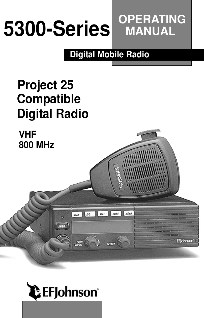
E. F. Johnson Company VHF Mobile Transceiver 5300 Operating Manual
UserManual.wiki
>
E F Johnson
>
2425326 User Manual
>
users manual
Contents
1.
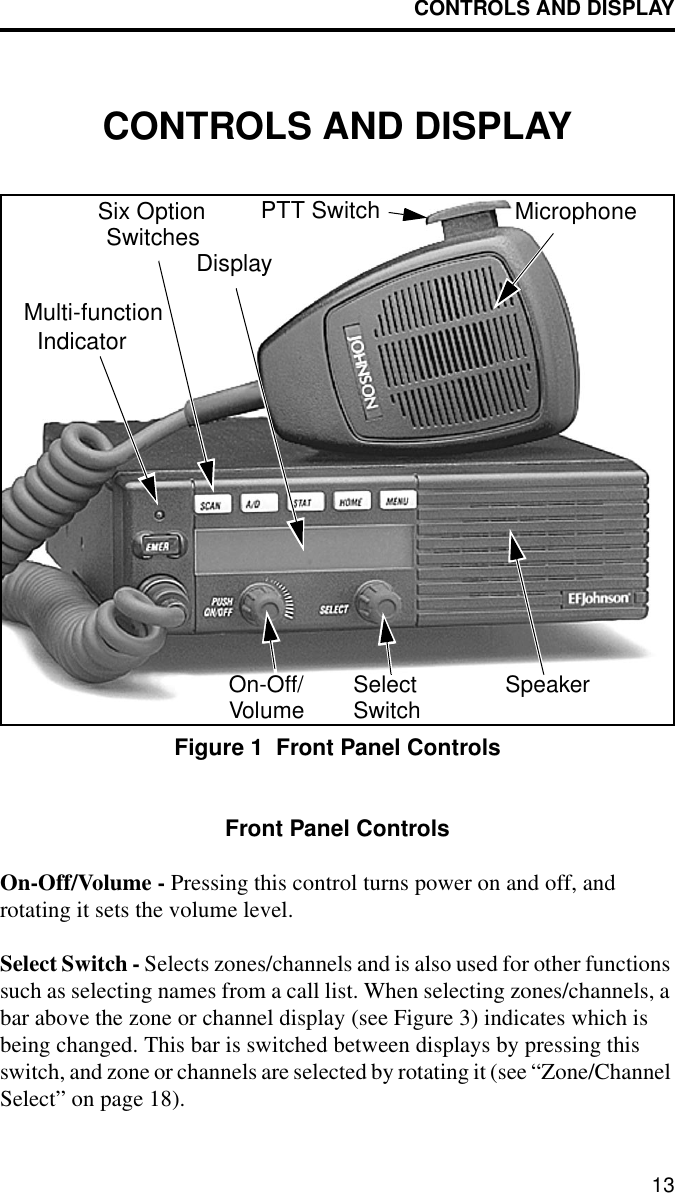
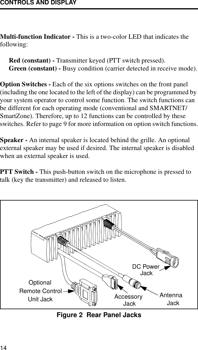
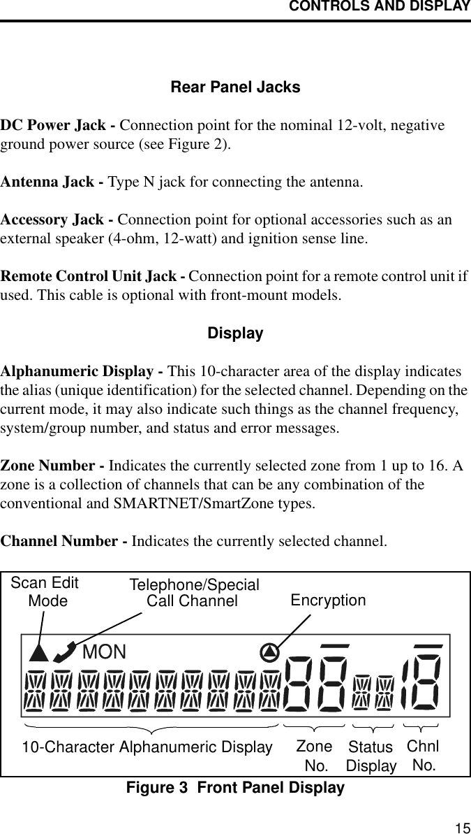
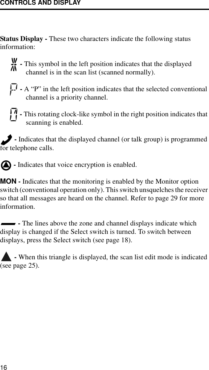
users manual
2.
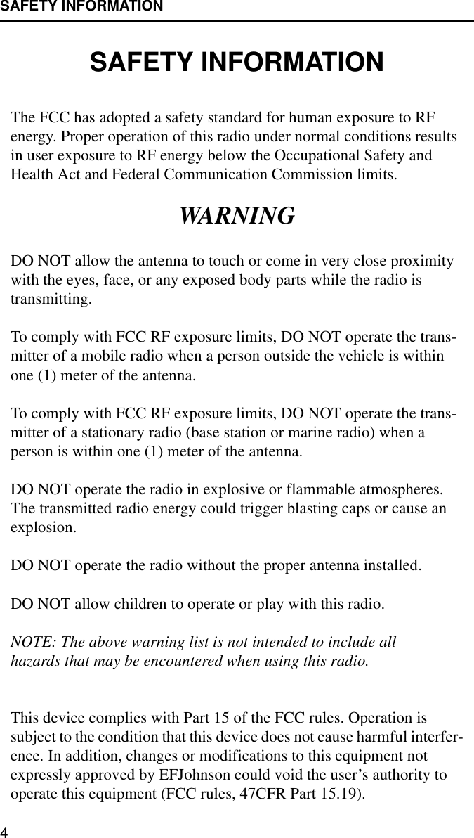
warning insert
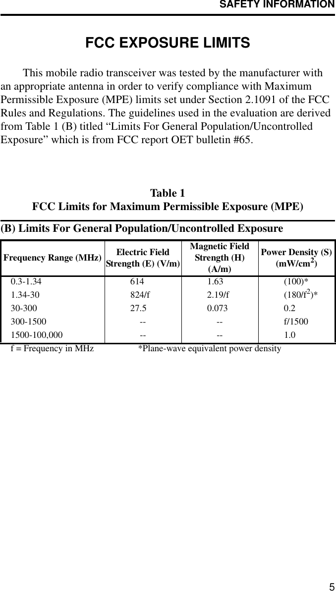
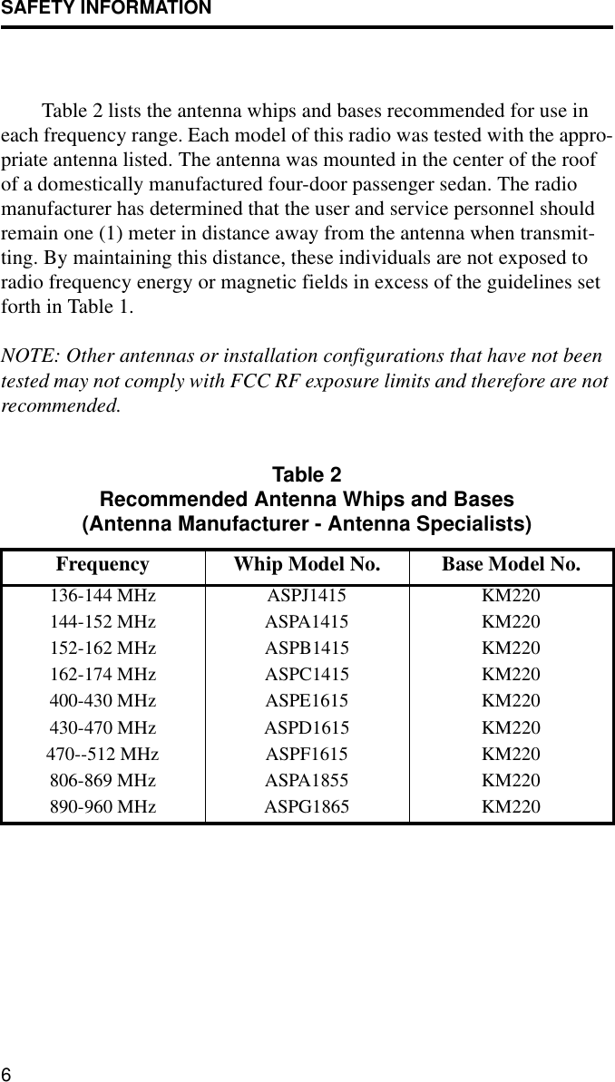
users manual
Navigation menu
Upload a User Manual
Namespaces
Wiki Guide
HTML
PDF
Info
Views
User Manual
Discussion / Help
Navigation