E F Johnson 2425326 VHF Mobile Transceiver User Manual 5300 Operating Manual
E. F. Johnson Company VHF Mobile Transceiver 5300 Operating Manual
Contents
- 1. users manual
- 2. warning insert
users manual
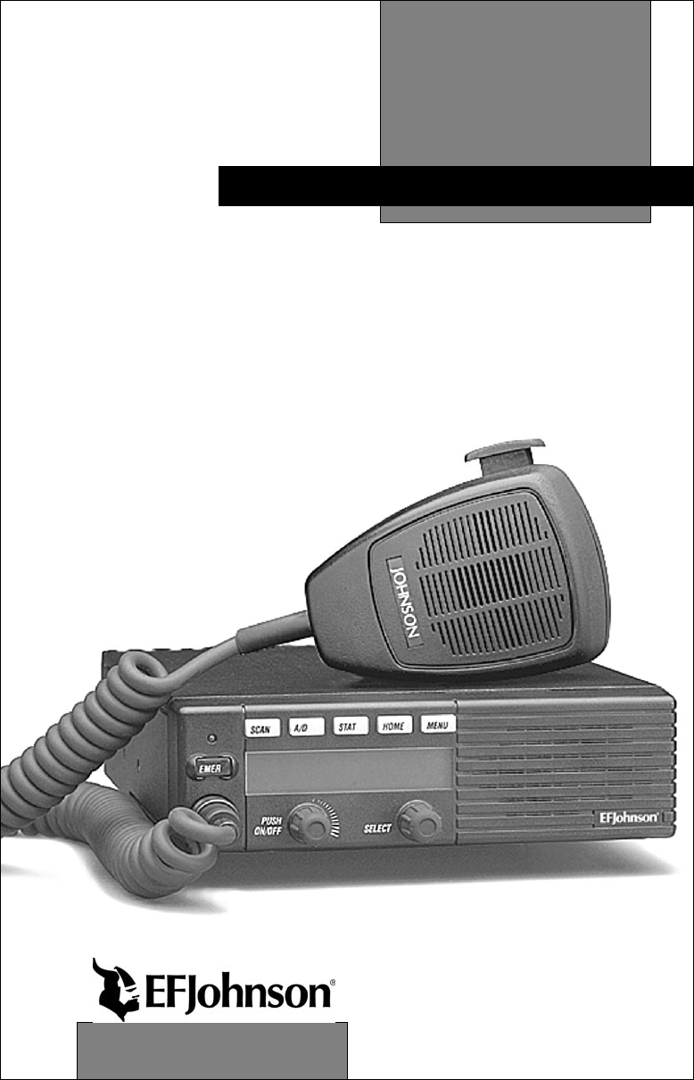
OPERATING
MANUAL
5300-Series
Digital Mobile Radio
Project 25
Compatible
Digital Radio
VHF
800 MHz
CHANGES FOR 7-01 REPRINT
Added Encryption key select and Select Sq Select sw info which
required reformatting entire manual. Chg’d PN to -005.
Page 9 - Added Hardware Key Select switch
Page 10 - Added Hardware Key Sel and Selective Sq Sel Sw
Page 11 - Moved Securenet info to General and added P25 to emerg
Page 17 - Changed view angle adj procedure
Page 19 - Added keypad programming info to squelch adj description
Page 21 - Added microphone hook info to scan description
Page 26 - Added hardware key select info to secure comminication
Page 29 - Added mic hook info to Monitor mode. Also, chg’d operation
when Mon switch pressed for 2 seconds
Page 31 - Added Selective Sq Select switch info
Page 33 - Adde P25 only to Emer Sw
Page 47 - Added “4 low tones’ bullet
Page 56 - Changed Site Lock description

LAND MOBILE PRODUCT WARRANTY - The manufacturer’s
warranty statement for this product is available from your product
supplier or from E.F. Johnson, 299 Johnson Avenue, Box 1249, Waseca,
MN 56093-0514. Phone (507) 835-6222.
Copyright© 2001 by the E.F. Johnson Company
E.F. Johnson Company, which was founded in 1923, designs, manufac-
tures, and markets radio communication products, systems, and services
worldwide. E.F. Johnson produces equipment for land mobile radio and
mobiletelephone services which include business, industrial, government,
public safety, and personal users.
Viking Head/EFJohnson logo and Call Guard® are trademarks of the E.F.
Johnson Company. SMARTNET™, SmartZone®, SecureNet™, Call
Alert™, Enhanced Private Conversation™, and Private Conversation II™
are trademarks of Motorola, Inc. All other company and/or product names
used in this manual are trademarks and/or registered trademarks of their
respective manufacturer. The IMBE™ voice coding technology embodied
in this product is protected by intellectual property rights including patent
rights of Digital Voice Systems, Inc.

SAFETY INFORMATION
4
SAFETY INFORMATION
The FCC has adopted a safety standard for human exposure to RF
energy. Proper operation of this radio under normal conditions results
in user exposure to RF energy below the Occupational Safety and
Health Act and Federal Communication Commission limits.
WARNING
DO NOT allow the antenna to touch or come in very close proximity
with the eyes, face, or any exposed body parts while the radio is
transmitting.
To comply with FCC RF exposure limits, DO NOT operate the trans-
mitter of a mobile radio when a person outside the vehicle is within
one (1) meter of the antenna.
To comply with FCC RF exposure limits, DO NOT operate the trans-
mitter of a stationary radio (base station or marine radio) when a
person is within one (1) meter of the antenna.
DO NOT operate the radio in explosive or flammable atmospheres.
The transmitted radio energy could trigger blasting caps or cause an
explosion.
DO NOT operate the radio without the proper antenna installed.
DO NOT allow children to operate or play with this radio.
NOTE: The above warning list is not intended to include all
hazards that may be encountered when using this radio.
This device complies with Part 15 of the FCC rules. Operation is
subject to the condition that this device does not cause harmful interfer-
ence. In addition, changes or modifications to this equipment not
expressly approved by EFJohnson could void the user’s authority to
operate this equipment (FCC rules, 47CFR Part 15.19).

SAFETY INFORMATION
5
FCC EXPOSURE LIMITS
This mobile radio transceiver was tested by the manufacturer with
an appropriate antenna in order to verify compliance with Maximum
Permissible Exposure (MPE) limits set under Section 2.1091 of the FCC
Rules and Regulations. The guidelines used in the evaluation are derived
from Table 1 (B) titled “Limits For General Population/Uncontrolled
Exposure” which is from FCC report OET bulletin #65.
Table 1
FCC Limits for Maximum Permissible Exposure (MPE)
(B) Limits For General Population/Uncontrolled Exposure
Frequency Range (MHz) Electric Field
Strength (E) (V/m)
Magnetic Field
Strength (H)
(A/m)
Power Density (S)
(mW/cm2)
0.3-1.34 614 1.63 (100)*
1.34-30 824/f 2.19/f (180/f2)*
30-300 27.5 0.073 0.2
300-1500 -- -- f/1500
1500-100,000 -- -- 1.0
f = Frequency in MHz *Plane-wave equivalent power density

SAFETY INFORMATION
6
Table 2 lists the antenna whips and bases recommended for use in
each frequency range. Each model of this radio was tested with the appro-
priate antenna listed. The antenna was mounted in the center of the roof
of a domestically manufactured four-door passenger sedan. The radio
manufacturer has determined that the user and service personnel should
remain one (1) meter in distance away from the antenna when transmit-
ting. By maintaining this distance, these individuals are not exposed to
radio frequency energy or magnetic fields in excess of the guidelines set
forth in Table 1.
NOTE: Other antennas or installation configurations that have not been
tested may not comply with FCC RF exposure limits and therefore are not
recommended.
Table 2
Recommended Antenna Whips and Bases
(Antenna Manufacturer - Antenna Specialists)
Frequency Whip Model No. Base Model No.
136-144 MHz ASPJ1415 KM220
144-152 MHz ASPA1415 KM220
152-162 MHz ASPB1415 KM220
162-174 MHz ASPC1415 KM220
400-430 MHz ASPE1615 KM220
430-470 MHz ASPD1615 KM220
470--512 MHz ASPF1615 KM220
806-869 MHz ASPA1855 KM220
890-960 MHz ASPG1865 KM220

TABLE OF CONTENTS
7
TABLE OF CONTENTS
SAFETY INFORMATION . . . . . . . . . . . . . . . . . . . . . . . . . . . . . . . . . . 4
OPTION SWITCH FUNCTIONS. . . . . . . . . . . . . . . . . . . . . . . . . . . . . 9
FEATURES . . . . . . . . . . . . . . . . . . . . . . . . . . . . . . . . . . . . . . . . . . . . . 11
General Features. . . . . . . . . . . . . . . . . . . . . . . . . . . . . . . . . . . . . . . . 11
Conventional Features . . . . . . . . . . . . . . . . . . . . . . . . . . . . . . . . . . . 11
SMARTNET™ II/SmartZone® Features. . . . . . . . . . . . . . . . . . . . . 11
CONTROLS AND DISPLAY. . . . . . . . . . . . . . . . . . . . . . . . . . . . . . . 13
Front Panel Controls. . . . . . . . . . . . . . . . . . . . . . . . . . . . . . . . . . . . . 13
Rear Panel Jacks. . . . . . . . . . . . . . . . . . . . . . . . . . . . . . . . . . . . . . . . 15
Display . . . . . . . . . . . . . . . . . . . . . . . . . . . . . . . . . . . . . . . . . . . . . . . 15
GENERAL OPERATION. . . . . . . . . . . . . . . . . . . . . . . . . . . . . . . . . . 17
Turning Power On . . . . . . . . . . . . . . . . . . . . . . . . . . . . . . . . . . . . . . 17
Backlight Control and Display Viewing Angle Adjust . . . . . . . . . . 17
Setting Volume Level. . . . . . . . . . . . . . . . . . . . . . . . . . . . . . . . . . . . 17
Zone/Channel Display . . . . . . . . . . . . . . . . . . . . . . . . . . . . . . . . . . . 18
Zone/Channel Select . . . . . . . . . . . . . . . . . . . . . . . . . . . . . . . . . . . . 18
Setting Squelch Control . . . . . . . . . . . . . . . . . . . . . . . . . . . . . . . . . . 19
Option Switches . . . . . . . . . . . . . . . . . . . . . . . . . . . . . . . . . . . . . . . . 19
Time-Out Timer . . . . . . . . . . . . . . . . . . . . . . . . . . . . . . . . . . . . . . . . 19
Home Zone Select . . . . . . . . . . . . . . . . . . . . . . . . . . . . . . . . . . . . . . 20
Tone Select . . . . . . . . . . . . . . . . . . . . . . . . . . . . . . . . . . . . . . . . . . . . 20
Power Turn-Off Delay . . . . . . . . . . . . . . . . . . . . . . . . . . . . . . . . . . . 20
Scanning . . . . . . . . . . . . . . . . . . . . . . . . . . . . . . . . . . . . . . . . . . . . . . 21
Secure Communication . . . . . . . . . . . . . . . . . . . . . . . . . . . . . . . . . . 26
Transceiver Operating Modes . . . . . . . . . . . . . . . . . . . . . . . . . . . . . 27
CONVENTIONAL FEATURES. . . . . . . . . . . . . . . . . . . . . . . . . . . . . 28
Introduction . . . . . . . . . . . . . . . . . . . . . . . . . . . . . . . . . . . . . . . . . . . 28
Monitoring Before Transmitting . . . . . . . . . . . . . . . . . . . . . . . . . . . 28
Monitor Mode. . . . . . . . . . . . . . . . . . . . . . . . . . . . . . . . . . . . . . . . . . 29
Busy Channel Lockout . . . . . . . . . . . . . . . . . . . . . . . . . . . . . . . . . . . 29
Call Guard Squelch. . . . . . . . . . . . . . . . . . . . . . . . . . . . . . . . . . . . . . 30
Penalty Timer . . . . . . . . . . . . . . . . . . . . . . . . . . . . . . . . . . . . . . . . . . 31
Conversation Timer . . . . . . . . . . . . . . . . . . . . . . . . . . . . . . . . . . . . . 32
Repeater Talk-Around . . . . . . . . . . . . . . . . . . . . . . . . . . . . . . . . . . . 32
Power Output Select. . . . . . . . . . . . . . . . . . . . . . . . . . . . . . . . . . . . . 32
Displaying Transmit/Receive Frequency . . . . . . . . . . . . . . . . . . . . . 33

TABLE OF CONTENTS
8
Emergency Mode . . . . . . . . . . . . . . . . . . . . . . . . . . . . . . . . . . . . . . . 33
Conventional Mode Scanning . . . . . . . . . . . . . . . . . . . . . . . . . . . . . 33
Priority Channel Sampling . . . . . . . . . . . . . . . . . . . . . . . . . . . . . . . . 34
Standard Conventional Calls . . . . . . . . . . . . . . . . . . . . . . . . . . . . . . 35
Project 25 Mode Features. . . . . . . . . . . . . . . . . . . . . . . . . . . . . . . . . 36
Keypad Programming. . . . . . . . . . . . . . . . . . . . . . . . . . . . . . . . . . . . 38
SMARTNET/SMARTZONE FEATURES . . . . . . . . . . . . . . . . . . . . 44
Introduction . . . . . . . . . . . . . . . . . . . . . . . . . . . . . . . . . . . . . . . . . . . 44
Viewing Unit ID. . . . . . . . . . . . . . . . . . . . . . . . . . . . . . . . . . . . . . . . 44
Standard Group Calls . . . . . . . . . . . . . . . . . . . . . . . . . . . . . . . . . . . . 44
Private (Unit-To-Unit) Calls. . . . . . . . . . . . . . . . . . . . . . . . . . . . . . . 45
Telephone Calls . . . . . . . . . . . . . . . . . . . . . . . . . . . . . . . . . . . . . . . . 48
Call Alert . . . . . . . . . . . . . . . . . . . . . . . . . . . . . . . . . . . . . . . . . . . . . 50
Messaging. . . . . . . . . . . . . . . . . . . . . . . . . . . . . . . . . . . . . . . . . . . . . 52
Sending Status Conditions . . . . . . . . . . . . . . . . . . . . . . . . . . . . . . . . 52
Emergency Alarm and Emergency Call. . . . . . . . . . . . . . . . . . . . . . 53
Failsoft Operation. . . . . . . . . . . . . . . . . . . . . . . . . . . . . . . . . . . . . . . 54
SMARTNET/SmartZone Scanning . . . . . . . . . . . . . . . . . . . . . . . . . 54
Dynamic Regrouping . . . . . . . . . . . . . . . . . . . . . . . . . . . . . . . . . . . . 54
SmartZone Features . . . . . . . . . . . . . . . . . . . . . . . . . . . . . . . . . . . . . 55
MISCELLANEOUS. . . . . . . . . . . . . . . . . . . . . . . . . . . . . . . . . . . . . . . 56
Supervisory Tones . . . . . . . . . . . . . . . . . . . . . . . . . . . . . . . . . . . . . . 56
System Operator Programming . . . . . . . . . . . . . . . . . . . . . . . . . . . . 58
Speaking Into Microphone . . . . . . . . . . . . . . . . . . . . . . . . . . . . . . . . 59
Operation At Extended Range . . . . . . . . . . . . . . . . . . . . . . . . . . . . . 59
Preventing Battery Discharge. . . . . . . . . . . . . . . . . . . . . . . . . . . . . . 59
Licensing . . . . . . . . . . . . . . . . . . . . . . . . . . . . . . . . . . . . . . . . . . . . . 60
Transceiver Service . . . . . . . . . . . . . . . . . . . . . . . . . . . . . . . . . . . . . 60
INDEX . . . . . . . . . . . . . . . . . . . . . . . . . . . . . . . . . . . . . . . . . . . . . . . . . . 61
OPTION SWITCH FUNCTIONS
9
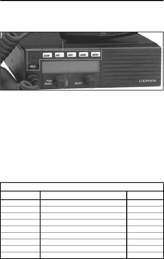
OPTION SWITCH FUNCTIONS
The six option switches with sample labels are shown above. Each
of these switches can control one function in the conventional mode and
another in the SMARTNET®/SmartZone™ mode.
The following tables indicate the functions available in each mode,
the key cap label normally used, and the page in this manual on which the
function is described. Since keys can control two different functions, the
key cap may not always indicate the correct function or a blank key cap
may be used. Consult your system operator to determine if some switches
control two different functions. Refer to page 19 for more option switch
information.
CONVENTIONAL MODE
Key Cap Label Function See Page
BKLHT Backlight On-Off 17
C/S Clear/Secure 26
TG SEL Talk Group Select 37
DISP Displayed Information 33
EMER Emergency 33
-Hardware Key Select 26
TX PWR Transmit Power 32
HOME Home Zone 20
CALL Individual ID Call (or Private Call) 37
Option Switches

OPTION SWITCH FUNCTIONS
10
CONVENTIONAL MODE (Cont’d)
Key Cap Label Function See Page
PROG Keypad Programming 38
MON Monitor 29
SEL SQ Normal/Selective Squelch 30
PRI SEL Priority 34
RWS Radio Wide Scan 22
RTA Repeater Talk-Around 32
SEL SQ Selective (Call Guard) Squelch Select 30
SCAN Scanning On-Off 21
SCN ED Scan List Edit 25
TONES Tones On-Off 20
SMARTNET/SMARTZONE MODE
Key Cap Label Function See Page
BKLHT Backlight 17
ALERT Call Alert 50
RESP Call Response 48
C/S Clear/Secure 26
EMER Emergency 53
-Hardware Key Select 26
HOME Home Zone 20
MSG Message 52
PHONE Phone 48
CALL Private Call (or Individual ID Call) 45
RWS Radio Wide Scan 22
SCAN Scanning On-Off 54
SCN ED Scan List Edit 25
LOCK Site Lock 56
SEARCH Site Search 56
STATUS Status 52
TONES Tones On-Off 20

FEATURES
11
FEATURES
General Features
•Programmable for the following modes of operation:
– Conventional analog
– Conventional Project 25 (digital)
– SMARTNET™/SmartZone® trunked (analog or digital)
•Up to 16 zones with up to 16 channels each programmable
(256 channels total)
•Large liquid crystal display (LCD) with backlight.
•Six programmable option switches
•Standard and radio wide scan modes
•Time-out timer
•SecureNet™ or 460 secure communication available on analog
channels, DES-OFB on digital channels
Conventional Features
•Up to 256 channels or talk groups programmable
•Repeater talk-around
•Monitor mode selected by microphone hanger or option switch
•Carrier or Call Guard® controlled squelch on analog channels
•Penalty and conversation timers
•Priority channel sampling when scanning
•Busy Channel Lockout (Transmit Disable On Busy)
•Individual ID calls on Project 25 channels
•User selectable high and low power output
•Emergency switch (P25 channels only)
•Keypad programming
SMARTNET™ II/SmartZone® Features
•Up to 256 talk groups programmable
•Group, Enhanced Private Conversation™, Private Conversation II™,
and Telephone Calls
•Emergency alarms to alert dispatcher of emergency conditions
•Emergency calling for high priority system access

FEATURES
12
•Failsoft operation on a predefined conventional channel if trunked
system fails
•Priority group calls detected while listening to other group calls
•Call Alert™ (send and receive pages)
•Predefined messages (up to 16) can be sent to a dispatcher
•Predefined status conditions (up to 8) can be sent to a dispatcher
•Dynamic regrouping (dispatcher can automatically gather users on a
channel to receive a message)
•Roaming (SmartZone only)
•SecureNet™ or 460 secure communication available
NOTE: The availability of many of the preceding features is
controlled by dealer programming of your transceiver, installed options,
and the capabilities of the radio system being accessed.
CONTROLS AND DISPLAY
13
CONTROLS AND DISPLAY
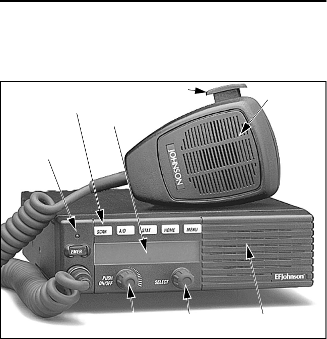
Figure 1 Front Panel Controls
Front Panel Controls
On-Off/Volume - Pressing this control turns power on and off, and
rotating it sets the volume level.
Select Switch - Selects zones/channels and is also used for other functions
such as selecting names from a call list. When selecting zones/channels, a
bar above the zone or channel display (see Figure 3) indicates which is
being changed. This bar is switched between displays by pressing this
switch, and zone or channels are selected by rotating it (see “Zone/Channel
Select” on page 18).
Six Option
Switches
Display
Microphone
PTT Switch
Speaker
Select
Switch
On-Off/
Volume
Multi-function
Indicator
CONTROLS AND DISPLAY
14
Multi-function Indicator - This is a two-color LED that indicates the
following:
Red (constant) - Transmitter keyed (PTT switch pressed).
Green (constant) - Busy condition (carrier detected in receive mode).
Option Switches - Each of the six options switches on the front panel
(including the one located to the left of the display) can be programmed by
your system operator to control some function. The switch functions can
be different for each operating mode (conventional and SMARTNET/
SmartZone). Therefore, up to 12 functions can be controlled by these
switches. Refer to page 9 for more information on option switch functions.
Speaker - An internal speaker is located behind the grille. An optional
external speaker may be used if desired. The internal speaker is disabled
when an external speaker is used.
PTT Switch - This push-button switch on the microphone is pressed to
talk (key the transmitter) and released to listen.
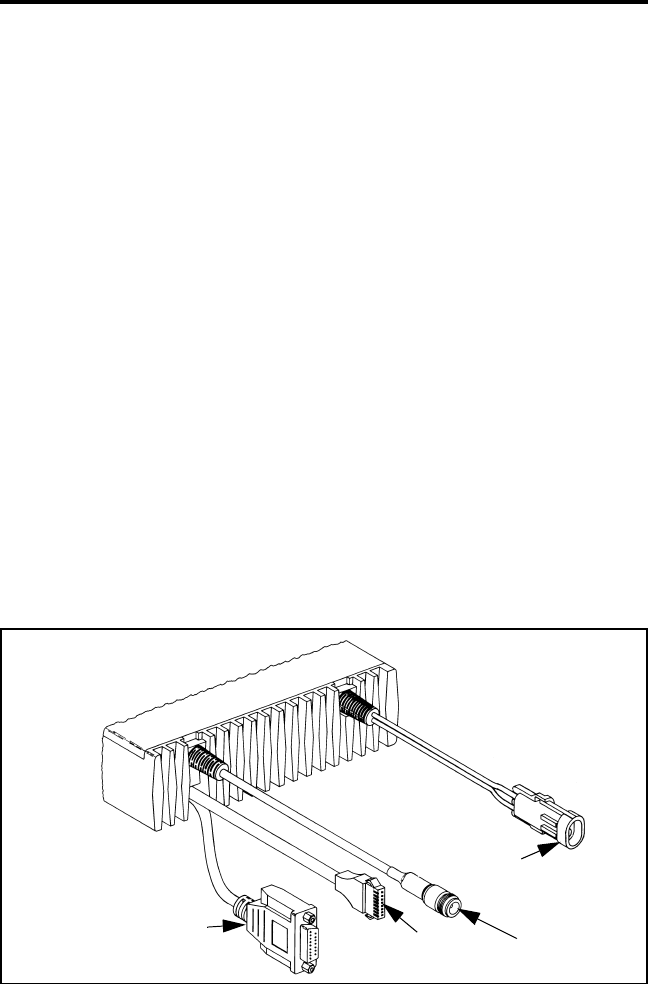
Figure 2 Rear Panel Jacks
Remote Control
Unit Jack Accessory
Jack
Antenna
Jack
DC Power
Jack
Optional

CONTROLS AND DISPLAY
15
Rear Panel Jacks
DC Power Jack - Connection point for the nominal 12-volt, negative
ground power source (see Figure 2).
Antenna Jack - Type N jack for connecting the antenna.
Accessory Jack - Connection point for optional accessories such as an
external speaker (4-ohm, 12-watt) and ignition sense line.
Remote Control Unit Jack - Connection point for a remote control unit if
used. This cable is optional with front-mount models.
Display
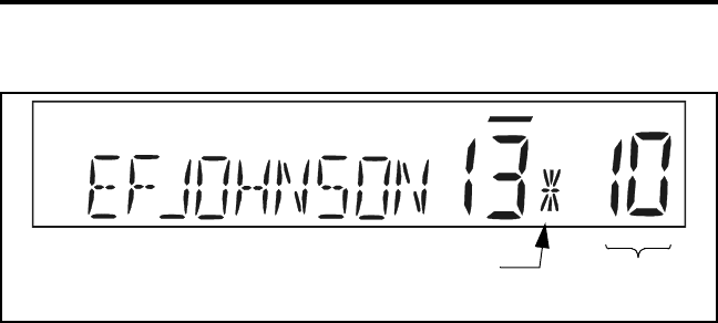
Alphanumeric Display - This 10-character area of the display indicates
the alias (unique identification) for the selected channel. Depending on the
current mode, it may also indicate such things as the channel frequency,
system/group number, and status and error messages.
Zone Number - Indicates the currently selected zone from 1 up to 16. A
zone is a collection of channels that can be any combination of the
conventional and SMARTNET/SmartZone types.
Channel Number - Indicates the currently selected channel.
Figure 3 Front Panel Display
Telephone/Special
Call Channel Encryption
10-Character Alphanumeric Display Zone
No. Status
Display Chnl
No.
Scan Edit
Mode
CONTROLS AND DISPLAY
16
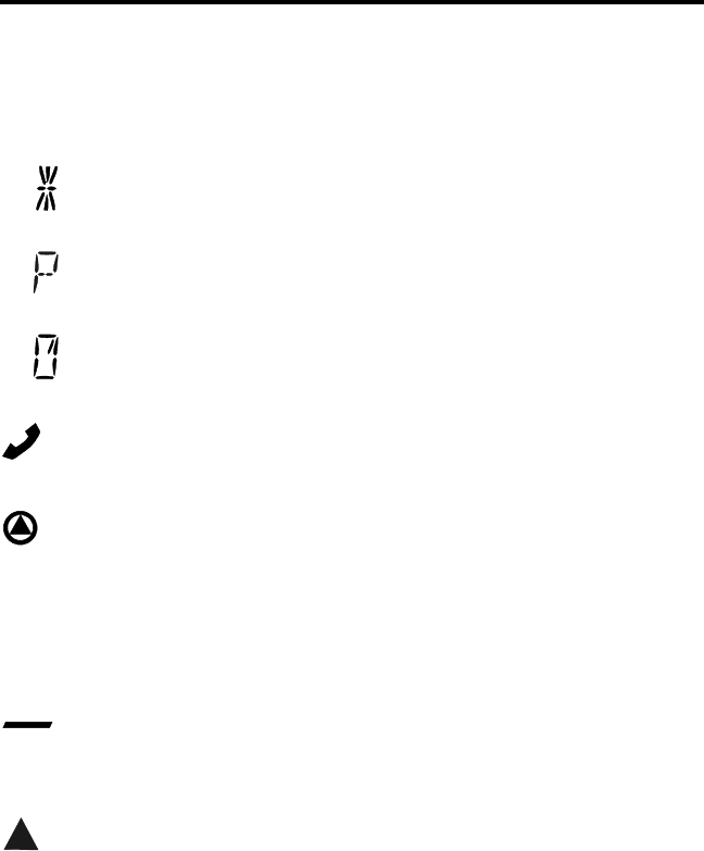
Status Display - These two characters indicate the following status
information:
- This symbol in the left position indicates that the displayed
channel is in the scan list (scanned normally).
- A “P” in the left position indicates that the selected conventional
channel is a priority channel.
- This rotating clock-like symbol in the right position indicates that
scanning is enabled.
- Indicates that the displayed channel (or talk group) is programmed
for telephone calls.
- Indicates that voice encryption is enabled.
MON - Indicates that the monitoring is enabled by the Monitor option
switch (conventional operation only). This switch unsquelches the receiver
so that all messages are heard on the channel. Refer to page 29 for more
information.
- The lines above the zone and channel displays indicate which
display is changed if the Select switch is turned. To switch between
displays, press the Select switch (see page 18).
- When this triangle is displayed, the scan list edit mode is indicated
(see page 25).

GENERAL OPERATION
17
GENERAL OPERATION
Turning Power On
When power is turned on by pressing the On-Off/Volume knob, the
multi-function indicator flashes green, a series of beeps sound, and an
initial greeting and operating mode are indicated by the alphanumeric
display. The zone and channel displays then indicate the currently
selected zone and channel. Programming determines if the last selected or
home zone is selected at power up.
Backlight Control and Display Viewing Angle Adjust
The backlight for the display and option keys can be manually
turned on and off if the BKLHT option switch is programmed. Otherwise,
it is fixed in the on or off mode by programming.
If the display is difficult to read from the angle you normally view it,
the viewing angle can be adjusted. Simply press and hold the last option
switch above the display and then press the first option switch above the
display. Then release both switches and turn the Select switch until the
best contrast is obtained. This function times out in 3-5 seconds.
Setting Volume Level
The relative volume setting can be determined by noting the position
of the index on the On-Off/Volume knob. Otherwise, enable a reference
tone for use in setting the volume as follows:
•If the key press tones are enabled (see page 20), a short tone sounds
when an option switch is pressed or the Select switch is pressed or
rotated.
•If a conventional channel is selected, take the microphone off-hook and
if someone is talking, voice is heard. If the MON (Monitor) option
switch is programmed (see page 29), pressing it unsquelches the trans-
ceiver and either voice or background noise is heard. If a SMARTNET/
SmartZone channel is selected, the transceiver cannot be manually
unsquelched.

GENERAL OPERATION
18
Zone/Channel Display
The selected zone and channel are displayed by the zone and
channel displays shown in Figure 3 on page 15. In addition, a unique
alphanumeric identification tag (alias) is displayed for each channel in the
alphanumeric display area. This unique identification is programmed by
your system operator.
A zone can include any mix of channels. Up to 16 zones can be
programmed, and up to 16 channels can be programmed in each zone for
a total of up to 256 channels. Zones may be used for operation in
different geographical areas or radio systems. Consult your system oper-
ator for more information on how to use the zones and channels that have
been programmed in your transceiver.
Zone/Channel Select
The front panel Select switch is used to change the zone and
channel. Pressing this switch toggles between the zone and channel select
modes, and rotating it changes the zone or channel.
The current mode is indicated by the bar over the zone or channel
display. For example, when the bar is over the zone display (see
following illustration), the zone select mode is enabled. Rotating the
Select switch clockwise increases the zone or channel and rotating it
counterclockwise decreases the zone or channel number. After the
Zone
No.
Chnl
No.
Zone Select Indicator
Channel Select Indicator

GENERAL OPERATION
19
highest zone or channel is displayed, wrap-around to the lowest zone or
channel occurs and vice versa. If an unprogrammed channel is selected,
“UNPROGRAMD” is displayed and a tone sounds. The transceiver may
also be programmed so that only programmed channels are selected.
The transceiver can be programmed so that the bar defaults to either
the zone or channel display when power is turned on and after a change is
made. The delay that occurs before it returns is programmed for 1-15
seconds or infinite (“infinite” causes it to remain in the last selected
mode).
Setting Squelch Control
This transceiver does not have a squelch control. The squelch level
is preset and usually does not require readjustment. However, if the
squelch level needs to be changed on a conventional channel, it can be
changed using keypad programming if available (see page 43).
Option Switches
The six option switches on the front panel (one is located to the left
of the display) can be programmed by your system operator to control a
different set of functions for each of the two different operating modes
(see page 27). Refer to page 9 for more information on these switches.
Time-Out Timer
The time-out timer disables the transmitter if it is keyed for longer
than the programmed time. It can be programmed on each channel for
times from 15 seconds up to 3 minutes, 45 seconds or it can be disabled.
If the transmitter is keyed continuously for longer than the programmed
time, the transmitter is disabled, a continuous tone sounds, and
“TX TIMEOUT” is displayed. Five seconds before time-out occurs, a
warning beep sounds to indicate that time-out is approaching. The timer
and tone are reset by releasing the PTT switch.
One use of this feature is to prevent a channel from being kept busy
for an extended period by an accidentally keyed transmitter. It can also

GENERAL OPERATION
20
prevent possible transmitter damage caused by transmitting for an exces-
sively long period.
Home Zone Select
If the HOME zone option switch is programmed, pressing it selects
the preprogrammed home zone. This provides a quick way of returning to
the home zone. The transceiver may also be programmed so that when-
ever power is turned on, the home or last selected zone is automatically
selected.
Tone Select
The various alert tones that sound are described starting on page 56.
These tones can be enabled and disabled if the TONE option switch is
programmed. To turn all tones off, press this switch and “TONE OFF” is
displayed. Then to turn all tones on again, press it and “TONE ON” is
displayed. If this switch is not programmed, tones are fixed in the on or
off condition by programming.
Power Turn-Off Delay
Your transceiver can be installed so that the vehicle ignition switch
as well as the front panel power switch control transceiver power. If this
is the case, both the ignition switch and the front panel power switch
must be on for transceiver power to turn on.
When the ignition switch controls power, a turn-off delay of up to
254 minutes can be programmed. The delay can be overridden at any
time by turning power off using the front panel power switch or turning
the ignition switch back on. A turn-off delay allows calls to be received
for a time after the ignition switch is turned off. At the same time, advan-
tages of ignition switch control are utilized such as preventing the battery
discharge that may occur if the transceiver is left on for an extended
period (see page 59).

GENERAL OPERATION
21
Scanning
Introduction
Scanning monitors the channels in the scan list for messages your
transceiver is programmed to receive. When a message is detected, scan-
ning stops and the message is received. Shortly after the message is
complete, scanning resumes (unless it has been disabled). The micro-
phone must on-hook for scanning to occur (unless the transceiver is
programmed to not detect the off-hook condition).
There are two scan modes available: Standard and Radio Wide. The
standard type is unique to the type of channel selected, and the Radio
Wide type is the same for all channel types. Only one type of scanning
can be enabled at a time. Therefore, if standard scanning is enabled when
the Radio Wide Scan switch is pressed, standard scanning is automati-
cally disabled and vice versa. Refer to the following for more
information.
Standard Scanning
Standard scanning monitors only channels that are the same type as
that currently selected. For example, if a conventional channel is selected,
only conventional channels are scanned. Standard scanning operates as
follows.
•To turn standard scanning on, press the SCAN option switch. Scanning
is enabled when a rotating is indicated in the right status display as
follows and “SCAN ON” is briefly displayed.
Scan Enable Indicator

GENERAL OPERATION
22
•To turn scanning off, press the SCAN option switch again and is no
longer indicated in the status display and “SCAN OFF” is briefly
displayed.
•If the zone or channel is changed while scanning is selected, scanning
continues on the same or a different scan list (see page 23).
Radio Wide Scanning
Radio wide scanning monitors the channels in the preprogrammed
radio wide scan list. This list may contain up to 16 channels of any type
assigned to any zone (see scan list description on page 23). Radio wide
scanning is turned on and off by the RWS option switch as follows. If
this switch is not programmed, radio wide scanning is not available.
•To turn radio wide scanning on, press the RWS option switch and
“RSCN ON” is briefly displayed. In addition, is displayed the same
as with standard scanning.
•To turn radio wide scanning off, press the RWS option switch again
and “RSCN OFF” is briefly displayed and is no longer displayed.
•If the zone or channel is changed while radio wide scanning,
scanning continues normally.
Scan Resume Delay
When a message is received or transmitted while scanning, there is a
system operator programmed delay before scanning resumes. The delay
after receiving a call prevents another message from being received
before you can make a response, and the delay after transmitting a call
ensures that you hear a response to your call instead of another message
occurring on some other channel.
Transmitting in the Scan Mode
If the transmitter is keyed while scanning is enabled, the transmis-
sion may occur on the receive, selected, or priority channel depending on
the operating mode and programming.

GENERAL OPERATION
23
Standard Mode Scan List
NOTE: The selected channel is always scanned.
With conventional operation, up to three scan lists can be
programmed. The list that is scanned is selected by the SCAN option
switch as described on page 33. Selecting another conventional channel
does not change the current scan list. The scan lists are user program-
mable if the SCN ED (Scan Edit) option switch is programmed (see
page 25).
With SMARTNET/SmartZone operation, each channel can be
programmed so that one of up to three different scan lists is selected or
scanning is disabled. As with conventional channels, the selected scan list
is user programmable if the SCN ED option switch is programmed.
Radio Wide Mode Scan List
With radio wide scanning, there is only one preprogrammed scan list
available regardless of the type of channel selected, and it is not user
programmable.
Determining Which Channels are in Scan List
Channels in the radio wide and conventional standard scan lists are
determined as follows. Channels in the SMARTNET/SmartZone standard
scan lists are indicated only when editing a list (see page 25).
1. Enable Standard scanning to view the standard list or Radio Wide scan-
ning to view the radio wide scan list (the procedure is on page 21). With
conventional standard scanning which can have up to three lists, also
select the scan list if applicable as described on page 33.
2. Select the desired zone and then scroll through the channels by rotating
the Select switch. When the displayed channel is in the scan list
(scanned normally), the symbol is displayed next to the zone number
as shown in the following illustration.
GENERAL OPERATION
24
Nuisance Channel Delete
With standard scanning, channels can be temporarily deleted from
the scan list, for example, if messages on a channel become annoying.
This feature is not available with radio wide scanning. Proceed as
follows:
NOTE: The selected channel and also conventional priority channels
cannot be deleted from the scan list.
1. While receiving a message on the channel to be deleted, press and hold
the SCAN option switch until a tone sounds (approximately 2 seconds).
2. The channel is then deleted and scanning of the remaining channels in
the scan list resumes.
3. Deleted channels are added back into the scan list if any of the
following events occur:
•Scanning is turned off and then on again using the SCAN switch.
•Transceiver power is turned off and then on again.
•The scan list is reselected by changing channels (SMARTNET/
SmartZone) or using the SCAN option switch (conventional).
Scan List Indicator Chnl
No.

GENERAL OPERATION
25
Programming a Scan List
If the SCN ED (Scan Edit) option switch is programmed, conven-
tional and SMARTNET/SmartZone standard scan lists can be user
programmed as follows:
1. Make sure that both standard and radio wide scanning are off (the
rotating icon is not indicated in the right status display). Then press
the SCN ED option switch and the scan edit mode is indicated by a
triangle in the upper left part of the display (see illustration on page 15).
2. With conventional channels, if applicable, select the list to be edited
(1-3) by rotating and then pressing the Select switch. The scan list is
indicated as “SCAN LIST x” (see page 33). If user programming is
disabled on a list, “NO LIST” is momentarily displayed and it cannot
be edited.
With SMARTNET/SmartZone channels, the scan list for the selected
channel is fixed and cannot be changed. Scanning may also be disabled
on the selected channel in which case “NO LIST” is momentarily
displayed and scan list editing is not available.
3. Select the channel you want to add or delete by rotating the Select
switch. After the last channel in the current zone is displayed, the first
valid channel in the next zone is displayed and vice versa.
SMARTNET/SmartZone lists are limited to 16 channels. If an attempt
is made to add more than 16, “LIST FULL” is displayed and a channel
must be deleted before another can be added.
4. If the selected channel is in the scan list (scanned), the symbol is
displayed next to the zone number as described on page 23. To change
the scan list status of the displayed channel, press the Select switch.
NOTE: The priority channel cannot be deleted (see “Priority Channel
Sampling” description which follows).
5. To exit this mode and save the changes, press the SCN ED option
switch again.

GENERAL OPERATION
26
Secure Communication
General
This transceiver may be optionally equipped to provide secure
communication on some or all channels. This feature encrypts your voice
so that it can be understood only by someone using a transceiver
equipped with a similar encryption device and encryption codes. If your
transceiver has this feature, consult your system operator for more infor-
mation on how it functions in your application.
When a secure call is received or transmitted, is indicated in the
display. Secure communication can be programmed on a per channel
basis to operate in various ways. If equipped with the C/S (Clear/Secure)
option switch and the current channel is programmed to allow switch
selection, secure communication can be manually enabled and disabled
by that switch. In the receive mode, secure calls may be autodetected or
only calls coded like the transmit signal may be received.
Hardware Key Select
With SecureNet encryption, up to sixteen hardware keys can be
programmed into the transceiver, and then each encrypted channel is
programmed to select a specific hardware key. The hardware key is actu-
ally the location in the transceiver of the encryption key that is used for a
call. The same encryption key may need to be selected in both the trans-
mitting and receiving transceivers for secure communication to occur.
If multiple keys have been programmed, the Hardware Key Select
option switch (if available) can be used to change the key associated with
a channel. This permanently changes the key for the channel (cycling
power or selecting another channel does not re-select the original key).
Therefore, to switch back to the original key, it must be manually
reselected. Proceed as follows to change a key:
1. Select the desired channel. Then press the Hardware Key Select option
switch and “HWKEY x” is displayed. The “x’ indicates the currently
selected key from 0-15.

GENERAL OPERATION
27
2. To select another key, rotate the Select switch to display the desired key
and then press the Select switch to select it. Press the Hardware Key
Select switch again to return to normal operation.
Transceiver Operating Modes
Each selectable channel can be programmed for either the conven-
tional or SMARTNET/SmartZone operating mode. For example, Zone 1/
Channel 1 could be a conventional channel, Zone 1/Channel 2 a
SMARTNET channel, and so on. Consult your system operator to deter-
mine the type or types of operation programmed in your transceiver.
More information on these modes follows.
Conventional - This is a non-trunked operating mode which accesses
independent radio channels (there is no automatic access to several chan-
nels). Monitoring before transmitting may not be automatic in this mode,
so you may need to manually monitor the channel before transmitting to
make sure that it is not in use. Either analog or digital (Project 25)
signaling may be used. Channel monitoring and other operating features
unique to conventional channels are described starting on page 28.
SMARTNET™/SmartZone® -This is a trunked operating mode that uses
ID codes to select what mobiles are being called and what calls are
received. Monitoring is performed automatically and special messages
and tones indicate busy and out-of-range conditions. Enhanced features
include roaming (SmartZone only), telephone, private, and emergency
calls, Call Alert™, and messaging. Either analog or digital signaling may
be used. Operating features unique to SMARTNET/SmartZone channels
are described starting on page 44.
When a SMARTNET or SmartZone channel is selected or the radio
is powered up on one of those channels, it searches for a control channel
and attempts to register on the radio system. Once a control channel is
found, the alias (name) of the selected channel is displayed. If a control
channel could not be found (because of an out of range condition or the
system ID is not correct, for example), “NO SYS” is displayed and the
radio continues to search for a control channel.

CONVENTIONAL FEATURES
28
The control channel transmits and receives system information to
and from all radios registered on the system. Therefore, once a control
channel is found, it is continuously monitored for incoming call informa-
tion and is used to make call requests. The radio automatically changes to
a traffic channel to place and receive calls and then returns to the control
channel when the call is complete.
CONVENTIONAL FEATURES
Introduction
An overview of the conventional operating mode is located on the
preceding page. The following information describes the features unique
to standard (analog) and Project 25 digital conventional operation. Refer
to the preceding “General Operation” section for information on features
common to all operating modes.
Monitoring Before Transmitting
With conventional operation, you may need to manually monitor the
channel before transmitting to make sure that it is not being used by
someone else. If you were to transmit while someone else was using the
channel, you would probably disrupt their conversation. Monitor conven-
tional channels automatically or manually as follows:
Automatic Channel Monitoring
If the selected channel is programmed for Busy Channel Lockout
feature (consult your system operator), monitoring is performed automat-
ically. Refer to the description of this feature on the next page for more
information.
Manual Channel Monitoring
The automatic monitoring just described may occasionally disable
the transmitter when the channel is not in use. In this case, it may not be
used and the channel must then be monitored manually as follows:

CONVENTIONAL FEATURES
29
Busy Indicator - With scanning disabled, note if the multi-function
indicator on the front panel (see Figure 1 on page 13) is steady green.
If it is not, the channel is not being used and you can transmit your call.
If it is green, the channel may be busy and you should not place your
call (see next paragraph).
Monitor Mode - There may be times when the busy indication is
displayed even though no one is using the channel. Monitoring should
then be performed using the monitor mode which follows.
Monitor Mode
The Monitor Mode temporarily disables squelch control features
(such as Call Guard squelch) so that all messages are heard on the
channel. To enable the monitor mode, briefly press the SEL SQ option
switch (if available) so that “Normal” is briefly displayed. Then to return
to normal operation, press this switch again (see page 30 for more
information).
The monitor mode can also be enabled by taking the microphone
off-hook (if off-hook detection is enabled by programming). This also
temporarily disables scanning if applicable. To return to normal opera-
tion, place the microphone back on-hook.
If the MON option switch is programmed, it can also be used to
enable monitoring and disable scanning. When monitoring is enabled by
this switch, “MON” is indicated in the display (see Figure 3 on page 15).
Pressing it a second time returns to normal operation. This function
unsquelches the receiver so that all activity, including background noise,
is heard. Therefore, it may also be useful during weak signal conditions if
intermittent squelching is making a message difficult to understand.
Pressing and holding the MON switch for at least 2 seconds when
scanning monitors the current scanned channel instead of the selected
channel (which may be different when receiving a call).

CONVENTIONAL FEATURES
30
Busy Channel Lockout
The Busy Channel Lockout feature (also called Transmit Disable On
Busy) automatically disables the transmitter if the channel is busy when
the PTT switch is pressed. When the transmitter is disabled by this
feature, “BUSY” is displayed and a tone sounds. This feature is
programmed to operate for one of the following modes:
Off - The feature is disabled and the transmitter keys even if the channel
is busy.
Noise - The transmitter is disabled if any signal is detected on the
channel.
Tone - The transmitter is disabled if the detected squelch coding is not
correct.
If busy channel override is enabled by programming, it is possible to
transmit when the transmitter is disabled by this feature. Simply release
the PTT switch and then quickly press it again.
Call Guard Squelch
General
Call Guard® squelch (also called CTCSS/DCS or selective
signaling) may be programmed on conventional channels. This feature
eliminates distracting messages intended for others using the channel.
This is accomplished by using a subaudible tone or digital code to control
the squelch. This tone or code is unique to a user or talk group on that
channel. It is transmitted by the mobile placing a call, and if Call Guard
squelch is programmed in the mobile receiving the call, it must detect the
correct tone or code to receive the call.
Call Guard Squelch Enable/Disable
The SEL SQ option switch (if available) can be used to temporarily
disable receive Call Guard squelch on the current channel. When it is
disabled, “NORMAL” is flashed in the display, and when it is enabled,
“SELECTIVE” is flashed. It is automatically re-enabled when another

CONVENTIONAL FEATURES
31
channel is selected or transceiver power is turned off and on. Call Guard
squelch can also be disabled by taking the microphone off-hook or
pressing the MON option switch as described on page 29.
Selective (Call Guard) Code Select
If the Selective Squelch Select option switch is programmed, the
Selective Squelch (Call Guard) code can be temporarily changed. This
switch is used to select a code from a pre-programmed list of up to 16
codes. Proceed as follows to change a code using this switch:
1. Press the Selective Squelch option switch and then rotate the Select
switch to select the desired code. The display indicates “SEL SQ xx”
where, “xx” is the selected code from 1-16.
2. To select the displayed code and return to the normal operation, press
the Selective Squelch switch again.
3. To check which code is selected, press the Selective Squelch switch
once to display the current selection and then again to return to normal
operation.
4. To return to the normal selective squelch codes, select “DEFAULT” in
this mode. The normal codes are also automatically reselected when-
ever transceiver power is cycled or a talk-around channel is selected.
NOTE: Call Guard codes can also be changed using the keypad
programming function described on page 38.
Penalty Timer
A penalty timer may be programmed on conventional channels to
prevent transmissions for a short period of time after the time-out timer
disables the transmitter (see page 19). The penalty timer starts when the
PTT switch is released after the transmitter has been disabled. If the PTT
switch is pressed during the penalty time, the time-out indication occurs
again. When the penalty timer expires, a beep sounds and the transmitter
can then be keyed.

CONVENTIONAL FEATURES
32
Conversation Timer
Besides the time-out timer described on page 19 and the penalty
timer just described, there is also a conversation timer that can be
programmed with conventional channels. This timer limits the total
length of a conversation rather than just the length of each transmission
as with the time-out timer.
If this timer is used, a warning tone sounds 5 seconds before it
expires. Then when it expires, the transmitter is disabled and a warning
tone sounds. The transmitter remains disabled for the length of the
penalty time just described, and a beep sounds when it can be keyed
again.
Repeater Talk-Around
Normally, all your transmissions go through a repeater which
usually increases range. However, if you are out of range of the repeater,
you cannot talk to anyone else on that repeater even though the mobile
you are calling may be only a short distance away. To allow communica-
tion when this situation occurs, repeater talk-around can be selected to
allow direct mobile-to-mobile communication.
Repeater talk-around can be selected if the RTA option switch is
programmed. When talk-around is enabled by this switch, “RTA ON” is
flashed in the display, and when it is disabled, “RTA OFF” is flashed.
This feature remains enabled during scanning, and changing channels or
turning power off does not change the selected mode.
Power Output Select
If the Tx PWR option switch is programmed and selectable power is
permitted on the current channel, high and low transmitter power can be
selected. Generally, the high power setting allows you to transmit longer
distances but uses more battery power. The opposite occurs with the low
power setting.

CONVENTIONAL FEATURES
33
Pressing the TX PWR switch toggles the power setting. The new
level is flashed in the display when this switch is pressed as “HIGH
POWER” or “LOW POWER”. If selectable power is not permitted on the
current channel, the fixed power level is flashed and no power change
occurs.
Displaying Transmit/Receive Frequency
If the DISP option switch is programmed, it can be used to display
the channel frequency in megahertz. Pressing this switch toggles between
displaying the standard channel identification and the frequency. The
receive frequency is displayed while receiving and the transmit frequency
is displayed while transmitting.
Emergency Mode
An EMER option switch may be programmed for use on conven-
tional Project 25 (digital) channels. This function could be used, for
example, to alert your dispatcher of an emergency condition. If you have
this switch, consult your system operator for more information on how it
is used in your application.
Conventional Mode Scanning
General
The following information describes scanning features unique to
conventional operation. Scan operation common to all modes is described
starting on page 21, and scan operation common to SMARTNET/Smart-
Zone operation is described starting on page 54.
Selecting Scan List
Up to three scan lists are available when standard scanning with a
conventional channel selected. These lists are preprogrammed by your
system operator, and the list to be scanned is selected by the SCAN
option switch as follows:

CONVENTIONAL FEATURES
34
1. Press the SCAN option switch to enable scanning and Scan List 1. This
is indicated when “SCAN LIST 1” is momentarily displayed.
2. To select Scan List 2 (if available), press the SCAN option switch again
and “SCAN LIST 2” is momentarily displayed. Repeat to display Scan
List 3 if available.
3. To disable scanning, press the SCAN switch again. Scanning is
disabled when scan indicator is no longer displayed.
Transmitting in Scan Mode
When the transmitter is keyed with scanning enabled, the transceiver
can be programmed so that the transmission always occurs on one of the
following channels:
•Priority channel (see following)
•Selected channel
•Channel of a call if the response is made before scanning resumes
Priority Channel Sampling
General
The priority channel sampling feature ensures that messages on the
priority channel are not missed while listening to a message on some
other channel. Your transceiver can be programmed so that the priority
channel is a fixed channel associated with the current scan list, the
currently selected channel, or not used.
Priority channel sampling occurs only with Standard conventional
scanning. It does not occur with Radio Wide scanning, when listening to
any type of SMARTNET/SmartZone call, or when transmitting. A series
of “ticks” may be heard when the priority channel is sampled while
listening to a message on some other channel. When the selected channel
is a priority channel, “P” is indicated in the left status display next to the
zone number as follows:

CONVENTIONAL FEATURES
35
Changing The Priority Channel
If a specific priority channel is associated with the current scan list,
it can be changed if the PRI SEL option switch is programmed. Proceed
as follows:
1. Make sure that both standard and radio wide scanning are off (the
rotating icon is not indicated in the right status display).
2. Select the channel that you want to be the priority channel using the
Select switch in the normal manner. If the channel is in a different zone,
also select the appropriate zone.
3. Press the PRI SEL option switch and “P” is indicated in the left status
display as just described to indicate that the selected channel is now the
priority channel.
Standard Conventional Calls
Standard conventional calls can be placed to other mobile units
monitoring the selected channel. The proper coded Call Guard squelch
tone or code may need to be transmitted by your transceiver for them to
receive your call (see page 30).
Placing a Standard Conventional Call
1. Turn power on and set the volume as described on page 17. Select the
channel programmed for the mobile you want to call (see “Zone/
Channel Select” on page 18).
Priority Indicator

CONVENTIONAL FEATURES
36
2. Monitor the channel automatically or manually as described on
page 28.
3. Press the PTT switch and the call proceeds as follows:
•If the Busy Channel Lockout feature is programmed on the channel,
the transmitter is automatically disabled if the channel is busy (see
description on page 30).
•Otherwise, busy and out-of-range conditions are not indicated and
speaking can begin after monitoring the channel.
4. Press (and hold) the PTT switch to talk and release it to listen. When the
call is finished, place the microphone back on-hook.
Receiving a Standard Conventional Call
1. Select or scan the channel programmed for the call you want to receive
(refer to pages 21 and 33 for more scanning information).
2. When the call is received, take the microphone off-hook and press the
PTT switch to talk and release it to listen. If scanning, you may have to
respond before scanning resumes to ensure that the response occurs on
the channel of the call.
3. When the call is finished, place the microphone back on-hook.
Project 25 Mode Features
Viewing Individual ID
Each transceiver which operates on Project 25 (digital) channels is
assigned an eight-digit individual ID. When power is turned on with a
Project 25 channel selected, the individual ID of your radio is briefly
displayed.

CONVENTIONAL FEATURES
37
Group IDs
Each Project 25 channel is programmed with a group ID code that
determines the group of mobiles which will receive your call on that
channel and also which calls you can receive.
Coded Squelch
Project 25 conventional channels use a NAC (Network Access
Code) instead of Call Guard squelch (see page 30) to control which calls
are received on a channel. Both the correct group ID and NAC must be
detected to receive a call. However, other operation, such as monitoring,
is similar to when Call Guard squelch is used.
Changing Talk Group Assigned To A Channel
If the TG SEL option switch is programmed, the talk group assigned
to a channel can be changed. This change is permanent (cycling power
does not reselect the old talk group). Proceed as follows:
1. Select the channel to be changed and then press the TG SEL option
switch.
2. Rotate the Select switch to display talk group to be assigned to that
channel. Talk groups are indicated by a unique identification in the
alphanumeric display.
3. To select that talk group and return to normal operation, press the TG
SEL switch again or press the Select switch. If talk group selection has
been disabled on the channel by programming, the talk group does not
change, “NO LIST” is displayed, and a tone sounds.
Individual Calls
If the CALL option switch is programmed, individual calls can be
placed to a specific mobile radio on Project 25 channels. This call differs
from standard group calls in that only one mobile instead of entire groups
of mobiles may receive the call. To respond to an individual call, simply

CONVENTIONAL FEATURES
38
press the PTT switch and begin talking before a call timer expires.
Proceed as follows to place this call:
1. Press the CALL option switch and the identification of the last indi-
vidual call placed is displayed.
2. If required, rotate the Select switch to display the identification of the
mobile you are calling.
3. Press the PTT switch and begin talking.
When individual calls are received, the transceiver may be
programmed to display the selected talk group, the talk group of the call,
or the ID of the calling radio.
Keypad Programming
Introduction
Keypad programming is available if the PROG option switch is
programmed. It is then selected by simply pressing that switch. The
keypad programming mode is indicated by “ZONE CHG” and blanked
Zone and Channel displays as follows:
Keypad programming allows conventional channel parameters such
as the transmit and receive frequency and Call Guard squelch code to be
changed. In addition, several conventional mode timers can be changed.
It cannot be used to reprogram unavailable channels or any SMARTNET/
SmartZone information.
CONVENTIONAL FEATURES
39
Menu Description
A menu system is used to select parameters to be changed in the
keypad programming mode. When the Keypad Programming mode is
selected by pressing the PROG option switch, the first menu parameter
“ZONE CHG” is displayed as just described. Rotate the Select switch to
scroll through the available parameters which are as follows. Additional
information on these parameters is located in the sections which follow.
•ZONE CHG
•CHAN CHG
•SYS PRM
•CHAN PRM
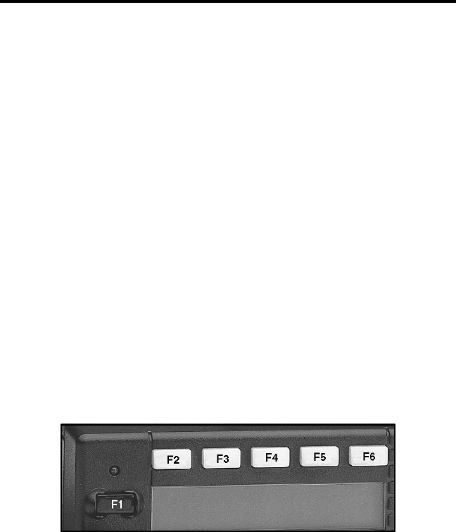
Press the Select switch or F6 key (see following illustration) to
select the displayed parameter. Press the F5 key from one of the main
menus to exit keypad programming. Pressing the F5 key in the other
menus returns to the previous menu. A flowchart showing the keypad
programming mode menu structure follows in Figure 4.
Key Identification For Keypad Programming
Zone Password
Your transceiver may be programmed so that a special password
must be entered before the system and channel parameters of a particular
zone can be changed. A different password may be required for each
zone. The first time a system or channel parameter of a password-
protected zone is selected by keypad programming, “PASSWORD” is
flashed. The eight-digit password must then be entered by rotating and
pressing the Select switch. After the correct password is entered, the
parameters for that zone can be reprogrammed normally.
CONVENTIONAL FEATURES
40
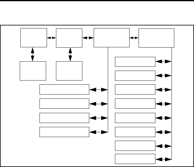
Figure 4 Keypad Programming Menu Flowchart
Zone Change Parameter
The “ZONE CHG” menu parameter selects the zone containing the
conventional channel to be reprogrammed. It does not change the zone
selected for normal operation. Press the Select switch to select the
“ZONE CHG” parameter and then scroll through the programmed zones
by rotating that switch. When the desired zone is displayed, select it by
pressing the Select switch.
Channel Change Parameter
The “CHAN CHG” menu parameter selects the conventional
channel to be reprogrammed. Unavailable or SMARTNET/SmartZone
channels cannot be selected. This does not change the channel selected
for normal operation. Press the Select switch to display “CHAN CHG”
Zone Channel
Change
Change System
Parameters
Channel
Parameters
Select
Zone
Select
Channel
Scan Hold Timer
Transmit Timer
Penalty Timer
Conver. Timer
Rx Freq
Tx Freq
Rx Code/NAC
Tx Code/NAC
Tx Power
Tx Timer
Chan Spacing
Squelch

CONVENTIONAL FEATURES
41
and then scroll through the programmed channels by rotating that switch.
When the desired channel is displayed, select it by pressing the Select
switch.
System Parameters
The “SYS PRM” menu parameter selects the conventional mode
timer to be reprogrammed (see following). Press the Select switch to
select “SYS PRM” and then rotate that switch to display the desired
parameter. Then press the Select switch again to select it. If
“PASSWORD” is briefly displayed, the zone password must be entered
as described on page 39 before parameters can be selected.
SCAN TMR - Selects the Scan Hold timer (see “Scan Resume Delay”
on page 22). Rotate the Select switch to decrement/increment the
timer in 0.5-second steps, and press the F2 key (see illustration on
page 39) to disable the timer (set it to 0 seconds). When the desired
value is displayed, store it by pressing the Select switch.
TX TMR - Selects the transmit time-out timer (see page 19). Rotate
the Select switch to decrement/increment the timer in 15-second steps,
and press the F2 key to disable the timer (set it to 0 seconds). When
the desired value is displayed, store it by pressing the Select switch.
PEN TMR - Selects the penalty timer (see page 31). Rotate the Select
switch to decrement/increment the timer in 15-second steps, and press
the F2 key to disable the timer (set it to 0 seconds). When the desired
value is displayed, store it by pressing the Select switch.
CONV TMR - Selects the conversation timer (see page 32). Rotate
the Select switch to decrement/increment the timer in 30-second steps,
and press the F2 key to disable the timer (set it to 0 seconds). When
the desired value is displayed, store it by pressing the Select switch.

CONVENTIONAL FEATURES
42
Channel Parameters
The “CHAN PRM” menu parameter selects the following conven-
tional channel parameters that can be reprogrammed. Press Select switch
to select the “CHAN PRM” parameter and then rotate that switch to
display the desired parameter. Then press the Select switch again to select
it. If “PASSWORD” is briefly displayed, the zone password must be
entered as described on preceding page before parameters can be
selected. The squelch control parameters are unique to the type of
conventional channel selected (analog or Project 25).
RX FREQ - Selects the receive channel frequency. To select the digit to
change, move the cursor right by pressing the Select switch or F4 key
(see illustration on page 39) and move it left by pressing the F3 key. Then
to display the desired digit, rotate the Select switch. When the desired
frequency is displayed, store it by pressing the F6 key. If an invalid
frequency is entered, a beep sounds, “INVALID” is briefly displayed, and
the frequency editing mode continues to be selected.
TX FREQ - Selects the transmit frequency the same as RX FREQ above.
Squelch Control (Analog Channel)
RX CODE - Selects the receive Call Guard (CTCSS/DCS) code (see
page 30). Rotate the Select switch to scroll through the available
codes. Press the F2 key (see illustration on page 39) once to display
the first available code, and press it again to toggle between types
(CTCSS and DCS). When the desired code is displayed, store it by
pressing the Select switch.
TX CODE - Selects the transmit codes the same as RX CODE above.
Squelch Control (Project 25 Channel)
RX NAC - Selects the Network Access Code (NAC) which can be
any number from 0-4095 (see “Coded Squelch” on page 37). Select

CONVENTIONAL FEATURES
43
the code using the Select switch and F3 and F2 keys the same as when
setting the receive frequency as described above. Press the F2 key (see
illustration on page 39) to reset the NAC to 0. When the desired code
is displayed, store it by pressing the F6 key. If an invalid code is
entered, a beep sounds, “INVALID” is briefly displayed, and the NAC
editing mode continues to be selected.
TX NAC - Selects the transmit NAC the same as RX NAC above.
TX POWER - Selects the desired power output level. Rotate the Select
switch to scroll through the following choices. When the desired setting
is displayed, store it by pressing the Select switch.
•POWER HI - High transmit power
•POWER LO - Low transmit power
•POWER SW - Switchable power selectable by the High/Low power
switch. This choice is not available if that switch is not
programmed.
TX TMR - Enables or disables the time-out timer on the current channel.
Rotate the Select switch to toggle between the on and off mode, and when
the desired setting is displayed, store it by pressing the Select switch.
CHAN SPC - Selects either wide or narrow band channel spacing on
analog channels only. Rotate the Select switch to toggle between
“WIDE” and “NARROW”, and when the desired setting is displayed,
store it by pressing the Select switch.
SQ ADJ - Changes the preset squelch level on the channel. The default
setting is “0” and values of –7 to +7 can be selected. Increasing this setting
causes the squelch to open sooner so that weaker signals can be received,
and decreasing it causes the opposite to occur.

SMARTNET/SMARTZONE FEATURES
44
SMARTNET/SMARTZONE FEATURES
Introduction
An overview of the SMARTNET/SmartZone operating mode is
located on page 27. The following information describes the features
unique to the SMARTNET and SmartZone operation. Refer to the
“General Operation” section starting on page 17 for information on
features common to all operating modes.
Viewing Unit ID
When power is turned on with a SMARTNET/SmartZone channel
selected, the six-digit Unit ID is briefly displayed as IDxxxxxx.
Standard Group Calls
Standard calls are between you and another mobile or control
station. Most calls you make will probably be this type.
Placing a Standard Group Call
1. Turn power on and set the volume as described on page 17. Select the
channel programmed for the talk group you want to call (see “Zone/
Channel Select” on page 18). A regular or announcement talk group
can be selected.
2. If encryption is used, it may be automatically selected. If not, select the
secure mode if desired by pressing the C/S (Clear/Secure) option
switch. Refer to “Secure Communication” on page 26 for more
information.
3. Press the PTT switch and begin talking. A talk permit tone may sound
to indicate when talking can begin. Other indications that may occur are
as follows:

SMARTNET/SMARTZONE FEATURES
45
•If in the secure mode and your transceiver does not have the proper
encryption key, “KEYFAIL” is displayed and the call must be made
in the clear mode.
•If the busy tone sounds and “BUSY” is displayed, the system is busy.
Release the PTT switch and wait for the call back tone to sound. Then
press the PTT switch within 3 seconds.
•If a continuous tone sounds and “NO SYS” is displayed, you may be
out-of-range. Drive closer or away from shielding objects and try
again.
•If your unit ID is invalid, the call is being made to an invalid group
ID, or if the talk group is not programmed for the selected secure
mode, “DISABLED ID” is displayed and an alert tone sounds.
•If an attempt is made to select the secure mode and there is no avail-
able secure channel, “NO SEC” is flashed and the call continues in the
clear mode.
•If an attempt is made to change from the secure to the clear mode and
this is not permitted, “SEC ONLY” is displayed and the call continues
in the secure mode.
Receiving a Standard Call
Group calls are automatically received if a SMARTNET/SmartZone
channel is selected. The display alternates between the selected channel
tag (alias) and the received talk group tag. The transceiver may also be
programmed so that the individual ID of the mobile placing the call is
briefly displayed before this information.
Private (Unit-To-Unit) Calls
General
Private calls allow you to place a call to a specific mobile unit.
Either the Enhanced Private Conversation™ or Private Conversation II™

SMARTNET/SMARTZONE FEATURES
46
mode may be programmed depending on the capabilities of the radio
system. Operation in both modes is described in the following informa-
tion. The CALL option switch is required to place these calls, and either
that switch or the RESP (Response) switch is required to receive them.
Proceed as follows.
Placing an Enhanced Private Conversation Call
1. Momentarily press the CALL (Private Call) option switch. The tag
(alias) of the last called mobile is displayed.
2. To select another mobile, rotate the Select switch until the tag for the
desired mobile is displayed.
3. Press the PTT switch and one of the following events then occurs:
•If the mobile being called is on the air, “WAIT” is displayed and
ringing is heard until the called party answers or for 20 seconds,
whichever occurs first. When the call is answered, the voice of the
called party is heard.
•If the called mobile does not answer within 20 seconds, a continuous
tone sounds and “NO ANS” is displayed.
•If the called mobile is not on the air, a continuous tone sounds instead
of the ringing tone and “NO ACK” is displayed.
•If the busy tone sounds and “BUSY” is displayed, the called mobile
has answered the call but the system is busy. When the system is no
longer busy, the call back tone sounds.
•If your transceiver or the called transceiver is inhibited or not
programmed to make this type of call or for the requested secure
mode, “REJECT” is displayed and an alert tone sounds.
•If your transceiver does not have the proper encryption key,
“KEYFAIL” is displayed and the call must be made in the clear mode

SMARTNET/SMARTZONE FEATURES
47
(selected by pressing the C/S (Clear/Secure) option switch if enabled
on the channel).
4. When the call is finished or is not answered, end it by pressing the
Private Call option switch and placing the microphone back on-hook.
Placing a Private Conversation II Call
1. Momentarily press the CALL (Private Call) option switch. The tag
(alias) of the last called mobile is displayed.
2. To select another mobile, rotate the Select switch until the tag for the
desired mobile is displayed.
3. Press the PTT switch and one of the following events then occurs:
•The called party answers the call.
•The called party does not answer. Press the CALL option switch to
end the call.
•If the selected mobile ID is not valid, “INVALID” is displayed and an
alert tone sounds.
•If the radio system is busy, four low tones sound and “BUSY” is
displayed. When the system is no longer busy, the call back tone (four
beeps) is heard and the channel is automatically acquired. Press the
PTT switch to continue the call.
•If the call is in the secure mode and your transceiver does not have the
proper encryption key, “KEYFAIL” is displayed and the call must be
made in the clear mode (selected by pressing the C/S (Clear/Secure)
option switch if enabled on the channel).
4. When the call is finished or if it is not answered, end it by pressing the
CALL option switch and placing the microphone on-hook.

SMARTNET/SMARTZONE FEATURES
48
Receiving a Private Call (All Types)
1. When a private call is received, “CALL” is displayed and a recurring
call tone sounds.
2. To answer the call, press the CALL (Private Call) option switch and
then the PTT switch and begin speaking. The unit ID of the calling
mobile is displayed. More information follows:
•If the PTT switch is pressed before the CALL switch, the call is
transmitted as a group call.
•If private calls are not permitted (CALL switch not programmed)
press the RESP (Call Response) option switch to respond.
•The call must be answered within 20 seconds or it is automatically
terminated.
•If the system is busy when a response is made, “BUSY” is displayed
and the busy tone sounds.
Telephone Calls
Telephone calls allow you to place and receive calls over the public
telephone system using your transceiver. The type of call (secure/clear) is
determined by the mode selected by the C/S (Clear/Secure) option
switch. Telephone calling is programmed to operate in one of the
following modes:
•Disabled (telephone calls not available)
•Answer-only capability
•Telephone numbers can be recalled from memory only
Placing a Telephone Call by Recalling a Number From Memory
1. With a SMARTNET/SmartZone channel selected, momentarily press
the PHONE option switch. The tag (alias) of the last called telephone
number is displayed.

SMARTNET/SMARTZONE FEATURES
49
2. If required, rotate the Select switch to display the desired number. The
tag of each number is displayed.
3. Press and then release the PTT switch and “DIALING” is displayed.
One of the following conditions then occur:
•If the access is successful, a dial tone sounds and the dialed number
is displayed and sent. Either ringing or a busy signal is then heard as
with a standard telephone call. When the called party answers, press
the PTT switch to talk and release it to listen (since the transceiver
operates half-duplex, it is not possible to talk and listen at the same
time).
Each time the PTT switch is released, a go-ahead tone is sent to the
landside party to indicate when they can respond. To dial a number
after the connection is made, press the PTT switch and dial the
number using the microphone keypad (if available).
•If the selected telephone number is not valid, “INVALID” is
displayed and an alert tone sounds. Select a valid number.
•If the system is busy, “BUSY” is displayed and the busy tone sounds.
The call will automatically proceed when the system becomes
available.
•If you are out-of-range or the radio cannot be accessed for some
reason, “NO PHONE” is displayed and an alert tone sounds.
•If the interconnect call you are making or the selected secure mode is
not authorized, “REJECT” is displayed and an alert tone sounds.
•If your transceiver does not have the proper encryption key,
“KEYFAIL” is displayed and the call must be made in the clear mode
(selected by pressing the C/S (Clear/Secure) option switch if enabled
on the channel).
4. When the telephone call is finished or it could not be completed for
some reason, end it by pressing the PHONE option switch and placing
the microphone back on-hook.

SMARTNET/SMARTZONE FEATURES
50
Answering a Telephone Call
1. When a telephone call is received, “ringing” similar to a standard tele-
phone is heard and “PHONE” is displayed.
2. To answer the call, press the PHONE option switch and press the PTT
switch to talk and release it to listen (since the transceiver operates half
duplex, it is not possible to talk and listen at the same time).
3. When the call is finished, end it by pressing the PHONE option switch
and placing the microphone back on-hook.
Call Alert
The Call Alert™ feature allows pages to be sent and received. Either
the Enhanced Private Conversation™ or Private Conversation II™ mode
may be programmed depending on the capabilities of the radio system.
The operation differences are noted in the procedure which follows.
Answering a Page
1. When a page is received, four beeps sound and “PAGE” is displayed.
The ID of the mobile paging you is stored as the last ID received.
2. To clear or ignore the page, press any option switch. If the PTT switch
is pressed, a group call is placed on the selected channel.
3. To answer the page as a private call (see page 45), press the CALL
(Private Call) option switch and the tag (alias) of the mobile paging you
is displayed. Press the PTT switch and respond. One of the conditions
that follow may also occur:
Enhanced Private Conversation™ Mode
•If the mobile being called is on the air, ringing is heard until the called
party answers or for 20 seconds, whichever occurs first. If no answer
occurs within 20 seconds, “NO ANS” is displayed.

SMARTNET/SMARTZONE FEATURES
51
•If the mobile being called is not on the air, no ringing is heard and
“NO ACK” is displayed.
Private Conversation II™ Mode
•If the mobile being called is not on the air or does not answer, you will
simply not hear a response.
4. When the call is finished or it could not be completed for some
reason, end it by pressing the CALL option switch and placing the
microphone back on-hook.
Initiating a Page
1. With a SMARTNET/SmartZone channel selected, momentarily press
the ALERT option switch. The tag (alias) of the last ID called is
displayed.
2. If required, rotate the Select switch to display the desired mobile. The
tag of each number is displayed.
3. Press the PTT switch and one of the following then occur:
•If a continuous tone sounds, the system received the page but the
called mobile is not on the air. Try again later or cancel the page by
pressing the ALERT switch again.
•If the called mobile does not answer within 6 seconds, a continuous
tone sounds and “NO ACK” is displayed. Try again later or cancel
the page by pressing the ALERT switch again.
•If five beeps sound, the system received the page and the paged
mobile is on the air and received it. The normal mode is automati-
cally reselected.

SMARTNET/SMARTZONE FEATURES
52
Messaging
The messaging feature allows preprogrammed messages to be sent
to your dispatcher. Up to 16 messages can be preprogrammed, and they
are identified by a tag (alias). If an MSG option switch is programmed,
messages are sent as follows:
1. Momentarily press the MSG option switch. The tag of the last message
sent is displayed.
2. If required, rotate the Select switch to display the desired message.
Then send the message by momentarily pressing the PTT switch. One
of the following then occurs:
•If five beeps sound, the message was received and acknowledged by
the dispatcher.
•If after 6 seconds, the message is not acknowledged, a tone sounds,
and “NO ACK” is displayed. Press and release the PTT switch to send
it again or press the Message option switch to exit the messaging
mode.
Sending Status Conditions
The status feature allows you to manually or automatically send
your current status to your dispatcher. Up to eight status conditions can be
preprogrammed, and they are identified by a tag (alias). If the STATUS
option switch is programmed, status conditions are sent as follows:
1. Momentarily press the STATUS option switch. The tag of the current
status condition is displayed.
2. To change the current status, rotate the Select switch until the desired
status is displayed. Then press the Select switch to accept that status.
3. You can wait to send the current status until polled by the dispatcher or
it can be sent immediately by briefly pressing the PTT switch. One of
the following then occurs:

SMARTNET/SMARTZONE FEATURES
53
•If five beeps sound, the status was received and acknowledged by the
dispatcher.
•If after 6 seconds, the message is not acknowledged, a tone sounds
and “NO ACK” is displayed. Press and release the PTT switch to send
it again or press the Status option switch to exit this mode and return
to normal operation.
Emergency Alarm and Emergency Call
Emergency alarms and emergency calls are separate functions that
can be individually programmed on SMARTNET/SmartZone channels.
The EMER option switch is also required to have these functions. An
emergency alarm is a special data transmission to alert your dispatcher of
an emergency situation, and an emergency call is an urgent request for
access to a voice channel. The emergency alarm and call are transmitted
on the programmed emergency talk group. Proceed as follows to initiate
an emergency alarm or call:
1. To transmit an emergency alarm, select a SMARTNET/SmartZone
channel that has that feature enabled and then press the EMER option
switch.
2. The emergency alarm is then transmitted and “EMERGENCY” is
indicated in the display for a short time. Transmitting continues until an
acknowledgment is received (indicated by two beeps) or the
programmed number of attempts have occurred.
3. To transmit an emergency call, press the EMER option switch with a
SMARTNET/SmartZone channel selected that has that feature enabled.
Then manually press the PTT switch and begin speaking as with a stan-
dard call. All calls that follow are then emergency calls and they occur
on the emergency talk group.
4. To exit the emergency mode, power must be turned off and then on
again.

SMARTNET/SMARTZONE FEATURES
54
Failsoft Operation
If a failure occurs in the SMARTNET/SmartZone system so that it
cannot be used, the transceiver automatically enters the failsoft mode.
When in this mode, “FAILSOFT” and the tag (alias) of the selected
channel are alternately displayed.
When in the failsoft mode, operation is in the conventional mode on
a preprogrammed failsoft channel. If a transmission is attempted before a
failsoft channel is located, a continuous tone sounds until the PTT switch
is released. When the radio system returns to normal operation, this
condition is automatically detected and normal operation resumes. The
secure mode is controlled by the C/S (Clear/Secure) option switch and
indicated by in the display. Secure calls are always automatically
detected.
SMARTNET/SmartZone Scanning
Scanning on a SMARTNET/Smartzone channel is similar to the
standard and radio wide scanning described starting on page 21. Each
channel can be programmed with a different scan list that includes up to
16 channels, on of which can be a priority channel. The scan lists are
programmable as described on page 25 if the SCN ED (Scan Edit) option
switch is programmed. In addition, channels can be programmed so that
scanning automatically starts or is disabled whenever the channel is
selected.
Messages on the priority channel are received while listening to
lower priority messages. However, unit-to-unit and telephone calls are
not interrupted by priority messages. Pages, unit-to-unit calls, and tele-
phone calls are received while scanning.
Dynamic Regrouping
The dynamic regrouping feature allows a dispatcher to switch
mobiles to a newly defined channel to receive an important message.
Dynamic regrouping operates as follows:

SMARTNET/SMARTZONE FEATURES
55
1. When this command is received, an alternating tone sounds for 5
seconds, the transceiver automatically changes to that channel, and the
display indicates the tag (alias) of the channel.
2. Manually select the channel corresponding to that tag. If this is not
done, transmission still occurs on the new channel, but an alternating
tone sounds each time the PTT switch is pressed.
3. Talk and listen as usual. The dispatcher will cancel dynamic
regrouping. If a standard channel is not selected after this occurs, an
error tone periodically sounds.
SmartZone Features
Introduction
As described on page 27, the SmartZone® mode provides wide area
coverage by allowing roaming between SMARTNET and conventional
sites. SmartZone operation is the same as SMARTNET with the
following additional features:
Busy Override
The busy override feature allows a call to be placed even if all of the
sites you are calling do not have a free traffic channel. This feature is
enabled and disabled by the system manager, and it operates as follows:
1. Assume that you have attempted to place a call and the system was busy
(“BUSY” displayed and busy tone sounded).
2. Release the PTT switch and then press it for 5 seconds or more. If a
chirp-like tone sounds with the PTT switch pressed, busy override is
occurring.
NOTE: Remember that not all members of the talk group are receiving
your message. Missing members will start receiving your message as
channels become available.

MISCELLANEOUS
56
Determining Current Site and Searching For a New Site
To determine the current radio site and the signal level of that site,
press the SEARCH option switch. The display then alternately indicates
the current site number as “SITE xx” and the signal level as “RSSI xx”.
To exit, press the SEARCH option switch again.
To scroll through the other programmed sites, rotate the Select
switch while “Site xx” or “RSSI xx” is displayed. To select the displayed
site and exit this mode, press the SEARCH option switch again. If site
lock is on when site search is entered (see following), the radio will be
locked on the new site when this function is exited.
Locking/Unlocking a Site
It is sometimes desirable to stay on a site. To prevent the transceiver
from searching for a new site, it can be locked on the current site. To lock
on the current site, press the LOCK option switch. The display momen-
tarily indicates “LOCK x” to indicate that the current site is locked (“x” is
the current site number). To unlock the site, press the LOCK option
switch again and “UNLOCK” is momentarily displayed.
MISCELLANEOUS
Supervisory Tones
Single Beep (Alert Tone)
•Power was turned on and a successful power-up sequence occurred (see
“Turning Power On” on page 17).
•The time-out timer is about to expire or the penalty timer has expired
(page 19).
•The conversation timer is about to expire (page 32).
•The system received your page but the paged mobile is not on the air
(page 50).
•Telephone interconnect is not operational (page 48).

MISCELLANEOUS
57
Continuous Tone (Invalid Condition)
•A transmission is being attempted on a conventional channel
programmed as receive-only.
•The transmitter is disabled by the transmit disable on busy feature
(page 30).
•The transmitter has been disabled by the time-out timer feature
(page 19).
•The transmitter has been disabled by the conversation timer (page 32).
•An out-of-range condition exists (SMARTNET/SmartZone only).
•A transmission is being attempted before the penalty timer has expired
(page 19).
•Dynamic regrouping has been exited but the dynamic regrouping
channel is still selected (page 54).
Single Short Medium-Pitch Tone
•A valid key has been pressed.
Single Short Low-Pitch Tone
•An invalid key has been pressed.
Medium Tone (No Acknowledge)
•The paged mobile did not acknowledge the page (page 50).
•The message that was sent has not been acknowledged (page 52).
•The status condition that was sent has not been acknowledged
(page 52).
Five Beeps (Recurring)
•The page was received (page 50).
Two Short Tones
•A unit-to-unit call was received (page 45).

MISCELLANEOUS
58
Five Beeps
•The paged mobile received the page and acknowledged it (page 50).
•The message that was sent has been received and acknowledged
(page 52).
•The status condition that was sent has been received and acknowledged
(page 52).
Four Beeps
•The emergency alarm condition was acknowledged (page 53).
Gurgle-Like Tone
•Dynamic regrouping has occurred (page 54).
•Dynamic regrouping has occurred but the regrouping channel is not
selected (page 54).
Busy Signal
•The radio system is busy or a busy condition exists when making a tele-
phone call.
Three Medium Pitch Tones
•A channel is available after a busy condition occurred (SMARTNET/
SmartZone only).
System Operator Programming
As noted several times in this manual, programming determines the
availability and specific operation of many features. This usually refers to
the programming performed by your system operator when the radio was
set up, not to any programming that you can perform. If a feature is
controlled by a front panel option switch and that switch is not available,
it is probably not available.

MISCELLANEOUS
59
If you require additional information on the operation of a feature,
contact your system operator. If the Keypad Programming option switch
is available, you can reprogram some conventional channel parameters.
Refer to “Keypad Programming” on page 38 for more information.
Speaking Into Microphone
For best results, hold the microphone about 1-2 inches from your
mouth and speak at a normal conversational level. Do not shout since it
distorts your voice and does not increase range. Make sure that the PTT
(push-to-talk) switch is pressed before you begin to speak and released as
soon as the message is complete.
Operation At Extended Range
When approaching the limits of radio range, the other party may not
be able to hear your transmissions and there may be an increase in back-
ground noise when messages are received. You may still be out of range
even though you can hear a message. The reason for this is that the signal
you are receiving is usually transmitted at a higher power level than the
one transmitted by your transceiver. Communication may be improved by
moving to higher ground or away from shielding objects such as tall
buildings or hills.
Preventing Battery Discharge
In the standby mode (power on, not transmitting), transceiver power
consumption is relatively low. Therefore, you can probably leave the
transceiver on for one or two days without operating the vehicle and the
battery should not become seriously discharged. However, if the outdoor
temperature is low enough to significantly decrease battery capacity, the
transceiver should be turned off when not in use.
Since power consumption is significantly higher when transmitting,
it is good practice to have the vehicle running while transmitting. This
ensures that optimum power is being delivered to the transceiver and that
the battery does not become discharged.

MISCELLANEOUS
60
Licensing
A government license is usually required to operate this transceiver
on the air. Your system operator will normally handle the licensing
requirements.
Transceiver Service
If “UNPROGRAMD” is displayed, the cause could be any of the
following:
•An unprogrammed channel is selected. Select a programmed
channel.
•The selected channel is programmed for an option that is not installed
or an error in programming was detected. Contact your system operator
for service.
If no characters or all characters appear in the display, the viewing
angle may be incorrect. Refer to page 17 for more information. If some
other problem is occurring, turn power off and then on again to reset the
control logic. Also make sure that the controls are properly set and that
the power, external speaker, and accessory cables (if used) are securely
plugged into the back of the transceiver. If the transceiver is completely
inoperative, check the power cable fuse that is usually located near the
vehicle battery. If it is blown, remedy the cause if possible and replace it
with the same type (15A). If the transceiver still does not operate prop-
erly, return it to your system operator for service.
NOTE: There are no user-serviceable components in the transceiver.
Altering internal adjustments can cause illegal emissions, void the
warranty, and result in improper operation that can seriously damage the
transceiver.

INDEX
61
INDEX
A
Alias 18
Alphanumeric Display 15
Antenna 6
B
Backlight 17
Battery Discharge 59
Busy Channel Lockout 29, 36
Busy Indicator 29
Busy Override 55
C
Call Alert (Paging) 50
Call Guard Squelch 30
Channel 15, 18
Conventional Mode 27
Conversation Timer 32
CTCSS Signaling 30
D
DCS Signaling 30
Delay, Scan Resume 22
Display 15
Display View Angle Adjust 17
Dynamic Regrouping 54
E
Emergency Alarms 53
Emergency Calls
Conventional 33
SMARTNET 53
Enh. Priv. Conversation Calls
Placing 46
Receiving 48
Extended Range Operation 59
F
Failsoft Operation 54
FCC Exposure Limits 5
Features
Conventional 11
General 11
Project 25 36
SMARTNET/SmartZone 11, 44
SmartZone 55
G
Group IDs, Project 25 37
H
Hardware Key 26
Home Zone Select 20
I
Indicator
Encryption 16, 26
Monitor 16
Priority Channel 16, 34
Scan 16
Scan List 16
Telephone Call 16
Individual Calls, Project 25 37
Individual ID, Project 25 36
J
Jack
Accessory 15
Antenna 15
DC Power 15
Remote Control Unit 15
K
Keypad Programming 38
L
Licensing 60
M
Messaging 52
Microphone Off-Hook 29

INDEX
62
Mode
Conventional 27
SMARTNET/SmartZone 27
Monitor Mode 29
Monitoring Before Transmitting 28
Multi-function Indicator 14
N
NAC 37
O
On-Off/Volume Control 13
Operating Modes 27
Option Switch
ALERT (Call Alert) 51
BKLHT 17
C/S (Clear/Secure) 26, 44, 47, 49, 54
CALL (Indiv Call) 37
CALL (Private Call) 46, 47, 48, 50
DISP (Displayed Information) 33
EMER (Emergency) 33, 53
Hardware Key Select 26
HOME (Zone) 20
LOCK (Site Lock) 56
MON (Monitor) 29
MSG (Message) 52
PHONE 48, 49, 50
PRI SEL (Priority Select) 35
PROG (Keypad Programming) 38
RESP (Call Response) 48
RTA (Repeater Talk-Around) 32
RWS (Radio Wide Scan) 22
SCAN 21, 23, 24, 33
SCN ED (Scan Edit) 25, 54
SEARCH (Site Search) 56
SEL SQ (Selective Squelch) 29, 30
Selective Squelch Select 31
STATUS 52
TG SEL (Talk Group Select) 37
TONE 20
TX PWR 32
Option Switch Functions 9
Option Switches 14
P
Paging 50
Answering 50
Initiating 51
Password
Zone 39
Penalty Timer 31
Power On-Off 17
Priority Calls
Conv 34
SMARTNET 54
Priority Channel, Changing 35
Priv. Conversation II Calls
Placing 47
Receiving 48
Private (Unit-To-Unit) Calls 45
Programming 58
PTT Switch 14
R
Repeater Talk-Around 32
RF Exposure 4
S
Safety Information 4
Scan List 22
Determining Channels in 23
Nuisance Channel Delete 24
Programming 25
Radio Wide Scan Mode 23
Selecting (Conv) 33
Standard Scan Mode 23
Scanning
Conventional 33
Radio Wide 22
SMARTNET 54
Standard 21
Secure Communication 26
Select Switch 13
Servicing 60
Site
Locking/Unlocking 56
Searching for 56
Site ID (SmartZone) 56

INDEX
63
SMARTNET/SmartZone Mode 27
Speaker 14
Speaking Into Microphone 59
Squelch Control 19, 43
Standard Calls
Placing (Conv) 35
Placing (SMARTNET) 44
Receiving (Conv) 36
Receiving (SMARTNET) 45
Status Display 16
Status Messages 52
Supervisory Tones 56
T
Tag 18
Talk-Around 32
Telephone Calls
Placing (SMARTNET) 48
Receiving (SMARTNET) 50
Time-Out Timer 19
Tone Select 20
Tones 56
Transmit Disable On Busy 30
Transmitting, Scan Mode 22, 34
Troubleshooting 60
U
Unit ID 44
V
Voice Encryption 26
Volume Level 17
Z
Zone 15, 18
Zone Password 39

Part No. 002-5300-005
07-01hph Printed in U.S.A.