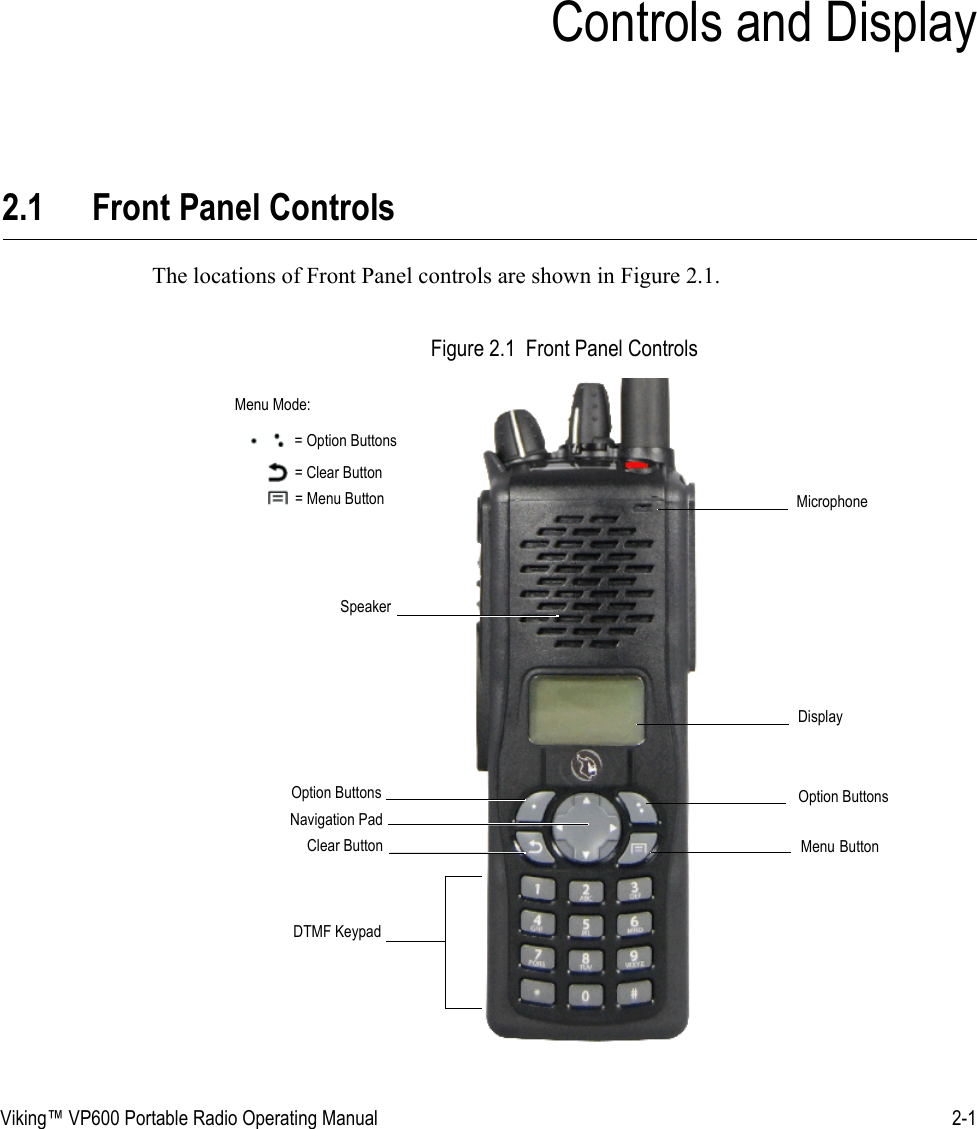
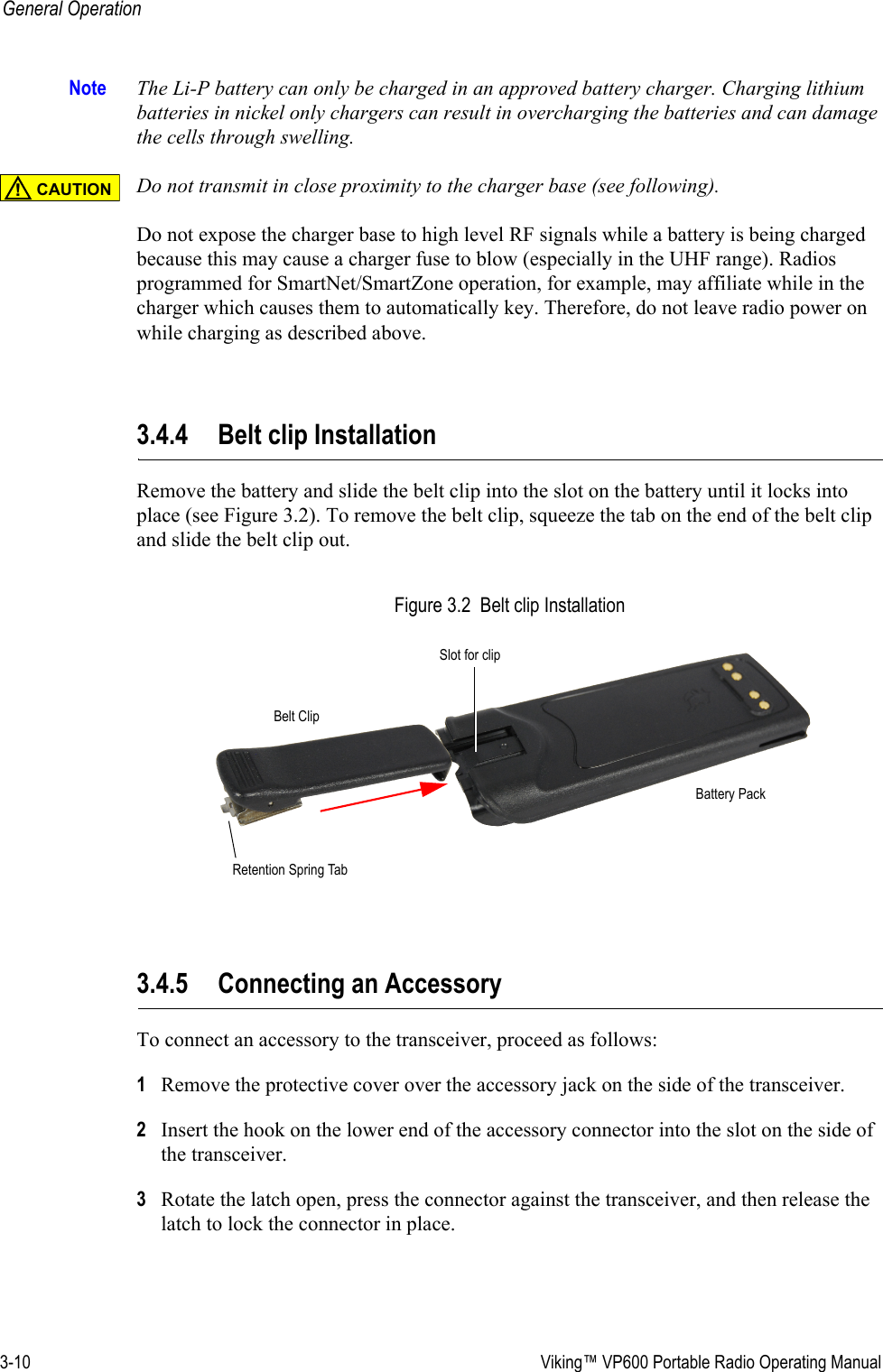
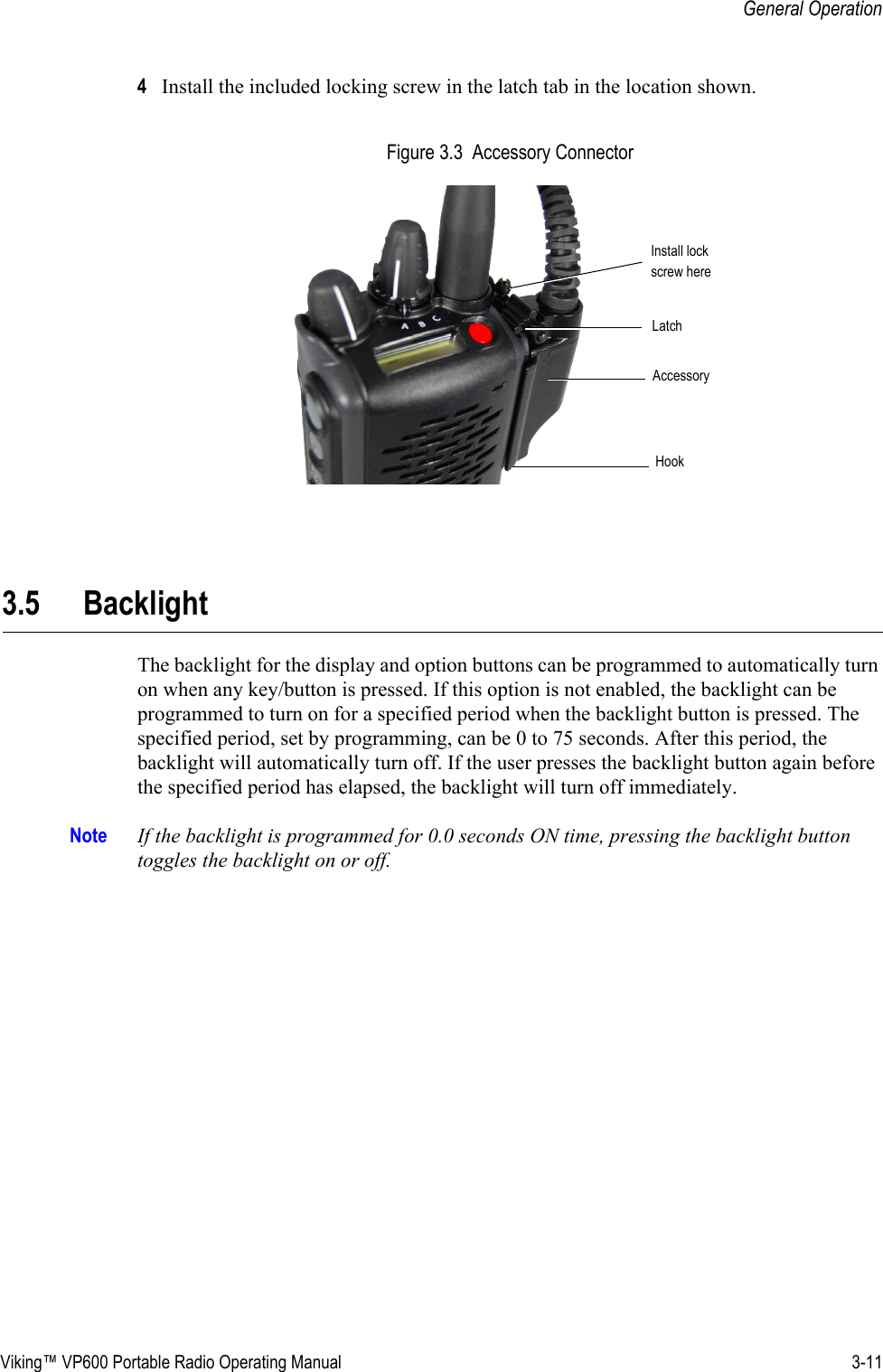
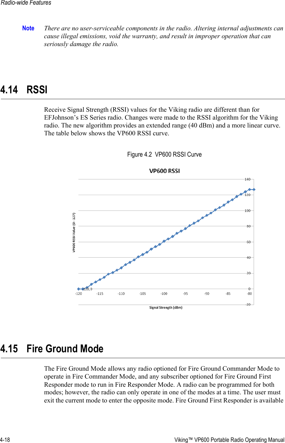
E F Johnson 2425795 VIKING P800 PORTABLE RADIO User Manual Viking VP600 Portable Radio Operating Manual

E. F. Johnson Company VIKING P800 PORTABLE RADIO Viking VP600 Portable Radio Operating Manual

User Manual

Viking™ VP600 Portable Radio Operating Manualfor theViking VP600 Model 3 RadioProject 25 Conventional and TrunkedSmartNet®/SmartZone®Analog and Digital ConventionalPart Number 002-0600-045March 2012
Copyright © 2012 by EF Johnson Technologies, Inc.The EFJohnson Technologies logo, Armada™, Trunked IP25™, and Call Guard® are trademarks of EF Johnson Technologies, Inc. All other company and/or product names used in this manual are trademarks and/or registered trademarks of their respective manufacturers.Software LicenseNon-open source software used in this product is licensed in accordance with EF Johnson Technologies, Inc.’s (“EFJohnson’s”) then current software license agreement.Open Source Software License Software used in this product includes open source software (“Open Source Software”) and is subject to the General Public License (“GPL”) provided at www.efjohnson.com. EFJohnson notifies you (“Licensee”) here-under that Licensee has the rights to obtain, modify and/or redistribute the source code of such software (“Open Source Software”) in accordance with the terms of such GPL. Therefore, if Licensee obtains such Open Source Software, Licensee must strictly adhere to the terms and conditions of the GPL.Information in this manual is subject to change without notice.Viking VP600 Portable Radio Operating ManualMarch 2012
Viking™ VP600 Portable Radio Operating Manual  iTable of ContentsViking VP600 Portable Radio Operating ManualMarch 2012Safety Requirements  ix1 Features 1-1General Features  . . . . . . . . . . . . . . . . . . . . . . . . . . . . . . . . . . . . . . . . . . . . . . . . . . . . . . . . . . . . . . . 1-1Conventional Features . . . . . . . . . . . . . . . . . . . . . . . . . . . . . . . . . . . . . . . . . . . . . . . . . . . . . . . 1-2Project 25 Trunked Features. . . . . . . . . . . . . . . . . . . . . . . . . . . . . . . . . . . . . . . . . . . . . . . . . . . 1-3SmartNet / SmartZone Features. . . . . . . . . . . . . . . . . . . . . . . . . . . . . . . . . . . . . . . . . . . . . . . . 1-4Available Options . . . . . . . . . . . . . . . . . . . . . . . . . . . . . . . . . . . . . . . . . . . . . . . . . . . . . . . . . . . . . . . 1-42 Controls and Display 2-1Front Panel Controls  . . . . . . . . . . . . . . . . . . . . . . . . . . . . . . . . . . . . . . . . . . . . . . . . . . . . . . . . . . . . 2-1Top Panel Controls. . . . . . . . . . . . . . . . . . . . . . . . . . . . . . . . . . . . . . . . . . . . . . . . . . . . . . . . . . . . . . 2-3Side Controls  . . . . . . . . . . . . . . . . . . . . . . . . . . . . . . . . . . . . . . . . . . . . . . . . . . . . . . . . . . . . . . . . . . 2-5Display. . . . . . . . . . . . . . . . . . . . . . . . . . . . . . . . . . . . . . . . . . . . . . . . . . . . . . . . . . . . . . . . . . . . . . . . 2-6Portable Icons . . . . . . . . . . . . . . . . . . . . . . . . . . . . . . . . . . . . . . . . . . . . . . . . . . . . . . . . . . . . . . 2-7RSSI Threshold Indications . . . . . . . . . . . . . . . . . . . . . . . . . . . . . . . . . . . . . . . . . . . . . . 2-10Signaling Tones  . . . . . . . . . . . . . . . . . . . . . . . . . . . . . . . . . . . . . . . . . . . . . . . . . . . . . . . . . . . . . . . 2-103 General Operation 3-1Turning Power On and Setting Volume  . . . . . . . . . . . . . . . . . . . . . . . . . . . . . . . . . . . . . . . . . . . . . 3-1Licensing. . . . . . . . . . . . . . . . . . . . . . . . . . . . . . . . . . . . . . . . . . . . . . . . . . . . . . . . . . . . . . . . . . 3-1Power Up  . . . . . . . . . . . . . . . . . . . . . . . . . . . . . . . . . . . . . . . . . . . . . . . . . . . . . . . . . . . . . . . . . 3-1Standard and Soft Power Down . . . . . . . . . . . . . . . . . . . . . . . . . . . . . . . . . . . . . . . . . . . . . . . . 3-2Persistent Settings  . . . . . . . . . . . . . . . . . . . . . . . . . . . . . . . . . . . . . . . . . . . . . . . . . . . . . . . . . . 3-3Setting Volume Level  . . . . . . . . . . . . . . . . . . . . . . . . . . . . . . . . . . . . . . . . . . . . . . . . . . . . . . . . 3-3Clock . . . . . . . . . . . . . . . . . . . . . . . . . . . . . . . . . . . . . . . . . . . . . . . . . . . . . . . . . . . . . . . . . . . . . . . . . 3-4Zone and Channel Select. . . . . . . . . . . . . . . . . . . . . . . . . . . . . . . . . . . . . . . . . . . . . . . . . . . . . . . . . 3-5Direct Zone / Channel Selection . . . . . . . . . . . . . . . . . . . . . . . . . . . . . . . . . . . . . . . . . . . . . . . . 3-5Zone Edit. . . . . . . . . . . . . . . . . . . . . . . . . . . . . . . . . . . . . . . . . . . . . . . . . . . . . . . . . . . . . . . . . . 3-7
ii Viking™ VP600 Portable Radio Operating ManualContentsBattery and Accessory Connector . . . . . . . . . . . . . . . . . . . . . . . . . . . . . . . . . . . . . . . . . . . . . . . . . 3-8Battery Removal / Installation . . . . . . . . . . . . . . . . . . . . . . . . . . . . . . . . . . . . . . . . . . . . . . . . . . 3-8Low Battery Indication. . . . . . . . . . . . . . . . . . . . . . . . . . . . . . . . . . . . . . . . . . . . . . . . . . . . . . . . 3-9Battery Charging . . . . . . . . . . . . . . . . . . . . . . . . . . . . . . . . . . . . . . . . . . . . . . . . . . . . . . . . . . . . 3-9Belt clip Installation . . . . . . . . . . . . . . . . . . . . . . . . . . . . . . . . . . . . . . . . . . . . . . . . . . . . . . . . . 3-10Connecting an Accessory . . . . . . . . . . . . . . . . . . . . . . . . . . . . . . . . . . . . . . . . . . . . . . . . . . . . 3-10Backlight . . . . . . . . . . . . . . . . . . . . . . . . . . . . . . . . . . . . . . . . . . . . . . . . . . . . . . . . . . . . . . . . . . . . .  3-11Keypad Lock . . . . . . . . . . . . . . . . . . . . . . . . . . . . . . . . . . . . . . . . . . . . . . . . . . . . . . . . . . . . . . . . . . 3-12Radio Inhibit . . . . . . . . . . . . . . . . . . . . . . . . . . . . . . . . . . . . . . . . . . . . . . . . . . . . . . . . . . . . . . . . . . 3-12Setting Squelch  . . . . . . . . . . . . . . . . . . . . . . . . . . . . . . . . . . . . . . . . . . . . . . . . . . . . . . . . . . . . . . . 3-13Transmit Disable. . . . . . . . . . . . . . . . . . . . . . . . . . . . . . . . . . . . . . . . . . . . . . . . . . . . . . . . . . . . . . . 3-13Operation At Extended Range  . . . . . . . . . . . . . . . . . . . . . . . . . . . . . . . . . . . . . . . . . . . . . . . . . . . 3-13Radio Operating Modes . . . . . . . . . . . . . . . . . . . . . . . . . . . . . . . . . . . . . . . . . . . . . . . . . . . . . . . . . 3-14Conventional Mode . . . . . . . . . . . . . . . . . . . . . . . . . . . . . . . . . . . . . . . . . . . . . . . . . . . . . . . . . 3-14SmartNet / SmartZone Mode  . . . . . . . . . . . . . . . . . . . . . . . . . . . . . . . . . . . . . . . . . . . . . . . . . 3-15P25 Trunked Mode . . . . . . . . . . . . . . . . . . . . . . . . . . . . . . . . . . . . . . . . . . . . . . . . . . . . . . . . . 3-15Systems, Channels, and Zones  . . . . . . . . . . . . . . . . . . . . . . . . . . . . . . . . . . . . . . . . . . . . . . . 3-16Conventional, Trunked Systems . . . . . . . . . . . . . . . . . . . . . . . . . . . . . . . . . . . . . . . . . . 3-16Channels . . . . . . . . . . . . . . . . . . . . . . . . . . . . . . . . . . . . . . . . . . . . . . . . . . . . . . . . . . . . 3-16Zones. . . . . . . . . . . . . . . . . . . . . . . . . . . . . . . . . . . . . . . . . . . . . . . . . . . . . . . . . . . . . . . 3-164 Radio-wide Features 4-1Viewing Radio Information  . . . . . . . . . . . . . . . . . . . . . . . . . . . . . . . . . . . . . . . . . . . . . . . . . . . . . . . 4-1Option Keys / Buttons . . . . . . . . . . . . . . . . . . . . . . . . . . . . . . . . . . . . . . . . . . . . . . . . . . . . . . . . . . . 4-2Feature Enable / Disable  . . . . . . . . . . . . . . . . . . . . . . . . . . . . . . . . . . . . . . . . . . . . . . . . . . . . . . . . . 4-4Menu Mode . . . . . . . . . . . . . . . . . . . . . . . . . . . . . . . . . . . . . . . . . . . . . . . . . . . . . . . . . . . . . . . . . . . . 4-5Function Recall. . . . . . . . . . . . . . . . . . . . . . . . . . . . . . . . . . . . . . . . . . . . . . . . . . . . . . . . . . . . . . . . . 4-7Time-Out Timer . . . . . . . . . . . . . . . . . . . . . . . . . . . . . . . . . . . . . . . . . . . . . . . . . . . . . . . . . . . . . . . . . 4-7Home Channel Select. . . . . . . . . . . . . . . . . . . . . . . . . . . . . . . . . . . . . . . . . . . . . . . . . . . . . . . . . . . . 4-8Power Output Select  . . . . . . . . . . . . . . . . . . . . . . . . . . . . . . . . . . . . . . . . . . . . . . . . . . . . . . . . . . . . 4-8Alert Tone Select. . . . . . . . . . . . . . . . . . . . . . . . . . . . . . . . . . . . . . . . . . . . . . . . . . . . . . . . . . . . . . . . 4-9Surveillance Mode  . . . . . . . . . . . . . . . . . . . . . . . . . . . . . . . . . . . . . . . . . . . . . . . . . . . . . . . . . . . . . . 4-9Scanning . . . . . . . . . . . . . . . . . . . . . . . . . . . . . . . . . . . . . . . . . . . . . . . . . . . . . . . . . . . . . . . . . . . . . . 4-9Priority Scanning. . . . . . . . . . . . . . . . . . . . . . . . . . . . . . . . . . . . . . . . . . . . . . . . . . . . . . . . . . . 4-10Radio Wide Scanning . . . . . . . . . . . . . . . . . . . . . . . . . . . . . . . . . . . . . . . . . . . . . . . . . . . . . . .  4-11Scan Hold Time. . . . . . . . . . . . . . . . . . . . . . . . . . . . . . . . . . . . . . . . . . . . . . . . . . . . . . . . . . . .  4-11Nuisance Channel Delete . . . . . . . . . . . . . . . . . . . . . . . . . . . . . . . . . . . . . . . . . . . . . . . . . . . . 4-12Scan Lists . . . . . . . . . . . . . . . . . . . . . . . . . . . . . . . . . . . . . . . . . . . . . . . . . . . . . . . . . . . . . . . . 4-12Group / Priority Scan Lists. . . . . . . . . . . . . . . . . . . . . . . . . . . . . . . . . . . . . . . . . . . . . . . 4-13Radio Wide Scan Lists  . . . . . . . . . . . . . . . . . . . . . . . . . . . . . . . . . . . . . . . . . . . . . . . . . 4-15Global Positioning System (GPS) . . . . . . . . . . . . . . . . . . . . . . . . . . . . . . . . . . . . . . . . . . . . . . . . . 4-16Viewing GPS Data  . . . . . . . . . . . . . . . . . . . . . . . . . . . . . . . . . . . . . . . . . . . . . . . . . . . . . . . . . 4-16
Viking™ VP600 Portable Radio Operating Manual iiiContentsSending GPS Data . . . . . . . . . . . . . . . . . . . . . . . . . . . . . . . . . . . . . . . . . . . . . . . . . . . . . . . . . 4-17Manually Sending GPS Data. . . . . . . . . . . . . . . . . . . . . . . . . . . . . . . . . . . . . . . . . . . . . 4-17Automatically Sending GPS Data . . . . . . . . . . . . . . . . . . . . . . . . . . . . . . . . . . . . . . . . . 4-17Sending GPS Data in Response to System Request . . . . . . . . . . . . . . . . . . . . . . . . . . 4-17Radio Service . . . . . . . . . . . . . . . . . . . . . . . . . . . . . . . . . . . . . . . . . . . . . . . . . . . . . . . . . . . . . . . . . 4-17RSSI . . . . . . . . . . . . . . . . . . . . . . . . . . . . . . . . . . . . . . . . . . . . . . . . . . . . . . . . . . . . . . . . . . . . . . . . . 4-18Fire Ground Mode. . . . . . . . . . . . . . . . . . . . . . . . . . . . . . . . . . . . . . . . . . . . . . . . . . . . . . . . . . . . . . 4-185 Conventional Mode Features 5-1Monitoring Before Transmitting  . . . . . . . . . . . . . . . . . . . . . . . . . . . . . . . . . . . . . . . . . . . . . . . . . . . 5-1Automatic Channel Monitoring . . . . . . . . . . . . . . . . . . . . . . . . . . . . . . . . . . . . . . . . . . . . . . . . . 5-1Manual Channel Monitoring  . . . . . . . . . . . . . . . . . . . . . . . . . . . . . . . . . . . . . . . . . . . . . . . . . . . 5-2Monitor Mode  . . . . . . . . . . . . . . . . . . . . . . . . . . . . . . . . . . . . . . . . . . . . . . . . . . . . . . . . . . . . . . . . . . 5-2Busy Channel Lockout. . . . . . . . . . . . . . . . . . . . . . . . . . . . . . . . . . . . . . . . . . . . . . . . . . . . . . . . . . . 5-3Call Guard Squelch  . . . . . . . . . . . . . . . . . . . . . . . . . . . . . . . . . . . . . . . . . . . . . . . . . . . . . . . . . . . . . 5-3Call Guard Squelch Enable / Disable . . . . . . . . . . . . . . . . . . . . . . . . . . . . . . . . . . . . . . . . . . . . 5-3Tone Call Guard Squelch  . . . . . . . . . . . . . . . . . . . . . . . . . . . . . . . . . . . . . . . . . . . . . . . . . . . . . 5-4Digital Call Guard Squelch . . . . . . . . . . . . . . . . . . . . . . . . . . . . . . . . . . . . . . . . . . . . . . . . . . . . 5-4Call Guard Disable . . . . . . . . . . . . . . . . . . . . . . . . . . . . . . . . . . . . . . . . . . . . . . . . . . . . . . . . . . 5-4Conventional Squelch Adjust  . . . . . . . . . . . . . . . . . . . . . . . . . . . . . . . . . . . . . . . . . . . . . . . . . . 5-5Selective Squelch Code Select (CTCSS / DCS / NAC)  . . . . . . . . . . . . . . . . . . . . . . . . . . . . . . 5-5Penalty Timer  . . . . . . . . . . . . . . . . . . . . . . . . . . . . . . . . . . . . . . . . . . . . . . . . . . . . . . . . . . . . . . . . . . 5-6Conversation Timer . . . . . . . . . . . . . . . . . . . . . . . . . . . . . . . . . . . . . . . . . . . . . . . . . . . . . . . . . . . . . 5-6Repeater Talkaround  . . . . . . . . . . . . . . . . . . . . . . . . . . . . . . . . . . . . . . . . . . . . . . . . . . . . . . . . . . . . 5-7Displaying Transmit / Receive Frequency . . . . . . . . . . . . . . . . . . . . . . . . . . . . . . . . . . . . . . . . . . . 5-7Emergency Alarm and Call  . . . . . . . . . . . . . . . . . . . . . . . . . . . . . . . . . . . . . . . . . . . . . . . . . . . . . . . 5-8Emergency Alarms . . . . . . . . . . . . . . . . . . . . . . . . . . . . . . . . . . . . . . . . . . . . . . . . . . . . . . . . . . 5-8Emergency Call Alert  . . . . . . . . . . . . . . . . . . . . . . . . . . . . . . . . . . . . . . . . . . . . . . . . . . . . . . . . 5-9Emergency Calls. . . . . . . . . . . . . . . . . . . . . . . . . . . . . . . . . . . . . . . . . . . . . . . . . . . . . . . . . . . . 5-9Emergency Hot Mic . . . . . . . . . . . . . . . . . . . . . . . . . . . . . . . . . . . . . . . . . . . . . . . . . . . . 5-10Placing an Emergency Call . . . . . . . . . . . . . . . . . . . . . . . . . . . . . . . . . . . . . . . . . . . . . . 5-10External Emergency Switch  . . . . . . . . . . . . . . . . . . . . . . . . . . . . . . . . . . . . . . . . . . . . . . . . . . 5-10Emergency Talkgroup . . . . . . . . . . . . . . . . . . . . . . . . . . . . . . . . . . . . . . . . . . . . . . . . . . . . . . . 5-11Conventional Mode Scanning . . . . . . . . . . . . . . . . . . . . . . . . . . . . . . . . . . . . . . . . . . . . . . . . . . . .  5-11Selecting a Scan List. . . . . . . . . . . . . . . . . . . . . . . . . . . . . . . . . . . . . . . . . . . . . . . . . . . . . . . .  5-11Transmitting in Scan Mode . . . . . . . . . . . . . . . . . . . . . . . . . . . . . . . . . . . . . . . . . . . . . . . . . . . 5-11Priority Channel Sampling. . . . . . . . . . . . . . . . . . . . . . . . . . . . . . . . . . . . . . . . . . . . . . . . . . . . 5-12Changing the Priority Channel. . . . . . . . . . . . . . . . . . . . . . . . . . . . . . . . . . . . . . . . . . . . 5-13Standard Conventional Calls. . . . . . . . . . . . . . . . . . . . . . . . . . . . . . . . . . . . . . . . . . . . . . . . . . . . . 5-13Placing a Standard Conventional Call. . . . . . . . . . . . . . . . . . . . . . . . . . . . . . . . . . . . . . . . . . . 5-13Receiving a Standard Conventional Call. . . . . . . . . . . . . . . . . . . . . . . . . . . . . . . . . . . . . . . . . 5-14ANI Signaling Options . . . . . . . . . . . . . . . . . . . . . . . . . . . . . . . . . . . . . . . . . . . . . . . . . . . . . . . . . . 5-14DTMF / ANI Signaling . . . . . . . . . . . . . . . . . . . . . . . . . . . . . . . . . . . . . . . . . . . . . . . . . . . . . . . 5-14
iv Viking™ VP600 Portable Radio Operating ManualContentsSingle Tone Encoder . . . . . . . . . . . . . . . . . . . . . . . . . . . . . . . . . . . . . . . . . . . . . . . . . . . . . . . . 5-15MDC1200 Compatibility  . . . . . . . . . . . . . . . . . . . . . . . . . . . . . . . . . . . . . . . . . . . . . . . . . . . . . 5-15Five-Tone Signaling. . . . . . . . . . . . . . . . . . . . . . . . . . . . . . . . . . . . . . . . . . . . . . . . . . . . . . . . . 5-16GE Star . . . . . . . . . . . . . . . . . . . . . . . . . . . . . . . . . . . . . . . . . . . . . . . . . . . . . . . . . . . . . . . . . . 5-16Two Tone Encoding. . . . . . . . . . . . . . . . . . . . . . . . . . . . . . . . . . . . . . . . . . . . . . . . . . . . . . . . . 5-16Project 25 Mode Features . . . . . . . . . . . . . . . . . . . . . . . . . . . . . . . . . . . . . . . . . . . . . . . . . . . . . . . 5-17Digital Unit ID  . . . . . . . . . . . . . . . . . . . . . . . . . . . . . . . . . . . . . . . . . . . . . . . . . . . . . . . . . . . . . 5-17Talkgroup ID  . . . . . . . . . . . . . . . . . . . . . . . . . . . . . . . . . . . . . . . . . . . . . . . . . . . . . . . . . . . . . . 5-17Network Access Code. . . . . . . . . . . . . . . . . . . . . . . . . . . . . . . . . . . . . . . . . . . . . . . . . . . . . . . 5-17Out of Range (EFJohnson Conventional) Indication. . . . . . . . . . . . . . . . . . . . . . . . . . . . . . . . 5-18Automatic (EFJohnson Conventional) Registration  . . . . . . . . . . . . . . . . . . . . . . . . . . . . . . . . 5-19P25 Group Calls . . . . . . . . . . . . . . . . . . . . . . . . . . . . . . . . . . . . . . . . . . . . . . . . . . . . . . . . . . . 5-19Changing a Channel Talkgroup . . . . . . . . . . . . . . . . . . . . . . . . . . . . . . . . . . . . . . . . . . . 5-20Talkgroup Scan . . . . . . . . . . . . . . . . . . . . . . . . . . . . . . . . . . . . . . . . . . . . . . . . . . . . . . . . . . . . 5-20Talkgroup Lock  . . . . . . . . . . . . . . . . . . . . . . . . . . . . . . . . . . . . . . . . . . . . . . . . . . . . . . . 5-20P25 Unit Calls . . . . . . . . . . . . . . . . . . . . . . . . . . . . . . . . . . . . . . . . . . . . . . . . . . . . . . . . . . . . . 5-22P25 Conventional Telephone Calls . . . . . . . . . . . . . . . . . . . . . . . . . . . . . . . . . . . . . . . . . . . . . 5-23Access / De-Access Codes . . . . . . . . . . . . . . . . . . . . . . . . . . . . . . . . . . . . . . . . . . . . . . 5-23Placing a Telephone Call . . . . . . . . . . . . . . . . . . . . . . . . . . . . . . . . . . . . . . . . . . . . . . . . 5-23Answering a Telephone Call  . . . . . . . . . . . . . . . . . . . . . . . . . . . . . . . . . . . . . . . . . . . . . 5-24Call Alert . . . . . . . . . . . . . . . . . . . . . . . . . . . . . . . . . . . . . . . . . . . . . . . . . . . . . . . . . . . . . . . . . 5-25Call History . . . . . . . . . . . . . . . . . . . . . . . . . . . . . . . . . . . . . . . . . . . . . . . . . . . . . . . . . . . . . . . 5-25Messaging. . . . . . . . . . . . . . . . . . . . . . . . . . . . . . . . . . . . . . . . . . . . . . . . . . . . . . . . . . . . . . . . 5-26Status Messaging . . . . . . . . . . . . . . . . . . . . . . . . . . . . . . . . . . . . . . . . . . . . . . . . . . . . . . . . . . 5-26P25 Packet Data . . . . . . . . . . . . . . . . . . . . . . . . . . . . . . . . . . . . . . . . . . . . . . . . . . . . . . . . . . . 5-27Keypad Programming  . . . . . . . . . . . . . . . . . . . . . . . . . . . . . . . . . . . . . . . . . . . . . . . . . . . . . . . . . . 5-27Menu Description  . . . . . . . . . . . . . . . . . . . . . . . . . . . . . . . . . . . . . . . . . . . . . . . . . . . . . . . . . . 5-28Zone Password . . . . . . . . . . . . . . . . . . . . . . . . . . . . . . . . . . . . . . . . . . . . . . . . . . . . . . . . . . . . 5-29Zone Change Parameter. . . . . . . . . . . . . . . . . . . . . . . . . . . . . . . . . . . . . . . . . . . . . . . . . . . . . 5-29Channel Change Parameter . . . . . . . . . . . . . . . . . . . . . . . . . . . . . . . . . . . . . . . . . . . . . . . . . . 5-29System Parameters. . . . . . . . . . . . . . . . . . . . . . . . . . . . . . . . . . . . . . . . . . . . . . . . . . . . . . . . . 5-30Channel Parameters . . . . . . . . . . . . . . . . . . . . . . . . . . . . . . . . . . . . . . . . . . . . . . . . . . . . . . . . 5-30CTCSS / DCS Squelch Control (Analog Channel)  . . . . . . . . . . . . . . . . . . . . . . . . . . . . 5-32NAC Squelch Control (Project 25 Channel). . . . . . . . . . . . . . . . . . . . . . . . . . . . . . . . . . 5-32Text Messaging. . . . . . . . . . . . . . . . . . . . . . . . . . . . . . . . . . . . . . . . . . . . . . . . . . . . . . . . . . . . . . . . 5-32Data Setup for Text Messaging. . . . . . . . . . . . . . . . . . . . . . . . . . . . . . . . . . . . . . . . . . . . . . . . 5-32Sending a Text Message. . . . . . . . . . . . . . . . . . . . . . . . . . . . . . . . . . . . . . . . . . . . . . . . . . . . . 5-33Receiving a Text Message  . . . . . . . . . . . . . . . . . . . . . . . . . . . . . . . . . . . . . . . . . . . . . . . . . . . 5-34Replying to a Received Text Message  . . . . . . . . . . . . . . . . . . . . . . . . . . . . . . . . . . . . . 5-34Viewing Previously Received Messages. . . . . . . . . . . . . . . . . . . . . . . . . . . . . . . . . . . . . . . . . 5-35Fire Ground Mode. . . . . . . . . . . . . . . . . . . . . . . . . . . . . . . . . . . . . . . . . . . . . . . . . . . . . . . . . . . . . . 5-356 SmartNet / SmartZone / P25 Trunked Features 6-1Analog and Digital Operation  . . . . . . . . . . . . . . . . . . . . . . . . . . . . . . . . . . . . . . . . . . . . . . . . . . . . . 6-1Standard Group Calls. . . . . . . . . . . . . . . . . . . . . . . . . . . . . . . . . . . . . . . . . . . . . . . . . . . . . . . . . . . . 6-1Placing a Standard Group Call . . . . . . . . . . . . . . . . . . . . . . . . . . . . . . . . . . . . . . . . . . . . . . . . . 6-2Receiving a Standard Group Call . . . . . . . . . . . . . . . . . . . . . . . . . . . . . . . . . . . . . . . . . . . . . . . 6-3Unit Calls . . . . . . . . . . . . . . . . . . . . . . . . . . . . . . . . . . . . . . . . . . . . . . . . . . . . . . . . . . . . . . . . . . . . . . 6-3Placing an Enhanced Unit Call . . . . . . . . . . . . . . . . . . . . . . . . . . . . . . . . . . . . . . . . . . . . . . . . . 6-4Placing a Standard Unit Call . . . . . . . . . . . . . . . . . . . . . . . . . . . . . . . . . . . . . . . . . . . . . . . . . . . 6-5
Viking™ VP600 Portable Radio Operating Manual vContentsReceiving a Unit Call (All Types). . . . . . . . . . . . . . . . . . . . . . . . . . . . . . . . . . . . . . . . . . . . . . . . 6-6Telephone Calls  . . . . . . . . . . . . . . . . . . . . . . . . . . . . . . . . . . . . . . . . . . . . . . . . . . . . . . . . . . . . . . . . 6-6Placing a Telephone Call. . . . . . . . . . . . . . . . . . . . . . . . . . . . . . . . . . . . . . . . . . . . . . . . . . . . . . 6-7Answering a Telephone Call . . . . . . . . . . . . . . . . . . . . . . . . . . . . . . . . . . . . . . . . . . . . . . . . . . . 6-8Call Alert . . . . . . . . . . . . . . . . . . . . . . . . . . . . . . . . . . . . . . . . . . . . . . . . . . . . . . . . . . . . . . . . . . . . . . 6-8Answering a Page. . . . . . . . . . . . . . . . . . . . . . . . . . . . . . . . . . . . . . . . . . . . . . . . . . . . . . . . . . . 6-8Initiating a Page  . . . . . . . . . . . . . . . . . . . . . . . . . . . . . . . . . . . . . . . . . . . . . . . . . . . . . . . . . . . . 6-9Messaging . . . . . . . . . . . . . . . . . . . . . . . . . . . . . . . . . . . . . . . . . . . . . . . . . . . . . . . . . . . . . . . . . . . . . 6-9Sending Status Conditions . . . . . . . . . . . . . . . . . . . . . . . . . . . . . . . . . . . . . . . . . . . . . . . . . . . . . . 6-10Emergency Alarm and Call  . . . . . . . . . . . . . . . . . . . . . . . . . . . . . . . . . . . . . . . . . . . . . . . . . . . . . . 6-10Emergency Alarms . . . . . . . . . . . . . . . . . . . . . . . . . . . . . . . . . . . . . . . . . . . . . . . . . . . . . . . . .  6-11Emergency Call Alert  . . . . . . . . . . . . . . . . . . . . . . . . . . . . . . . . . . . . . . . . . . . . . . . . . . . . . . .  6-11Emergency Calls. . . . . . . . . . . . . . . . . . . . . . . . . . . . . . . . . . . . . . . . . . . . . . . . . . . . . . . . . . . 6-12Emergency Hot Mic . . . . . . . . . . . . . . . . . . . . . . . . . . . . . . . . . . . . . . . . . . . . . . . . . . . . 6-12Placing an Emergency Call . . . . . . . . . . . . . . . . . . . . . . . . . . . . . . . . . . . . . . . . . . . . . . 6-12External Emergency Feature  . . . . . . . . . . . . . . . . . . . . . . . . . . . . . . . . . . . . . . . . . . . . . . . . . 6-13Failsoft Operation. . . . . . . . . . . . . . . . . . . . . . . . . . . . . . . . . . . . . . . . . . . . . . . . . . . . . . . . . . . . . . 6-13Failsoft Connect Tone . . . . . . . . . . . . . . . . . . . . . . . . . . . . . . . . . . . . . . . . . . . . . . . . . . . . . . . 6-14SmartNet / SmartZone / P25 Trunked Scanning Features  . . . . . . . . . . . . . . . . . . . . . . . . . . . . . 6-14Priority Talkgroup Sampling  . . . . . . . . . . . . . . . . . . . . . . . . . . . . . . . . . . . . . . . . . . . . . . . . . . 6-15Dynamic Regrouping . . . . . . . . . . . . . . . . . . . . . . . . . . . . . . . . . . . . . . . . . . . . . . . . . . . . . . . . . . . 6-16SmartZone and P25 Trunking Unique Features. . . . . . . . . . . . . . . . . . . . . . . . . . . . . . . . . . . . . . 6-16Busy Override . . . . . . . . . . . . . . . . . . . . . . . . . . . . . . . . . . . . . . . . . . . . . . . . . . . . . . . . . . . . . 6-16Site Trunking . . . . . . . . . . . . . . . . . . . . . . . . . . . . . . . . . . . . . . . . . . . . . . . . . . . . . . . . . . . . . . 6-17Determining Current Site and Searching For New Site. . . . . . . . . . . . . . . . . . . . . . . . . . . . . . 6-17Locking / Unlocking a Site. . . . . . . . . . . . . . . . . . . . . . . . . . . . . . . . . . . . . . . . . . . . . . . . . . . . 6-18Auto Site Search . . . . . . . . . . . . . . . . . . . . . . . . . . . . . . . . . . . . . . . . . . . . . . . . . . . . . . . . . . . 6-18ZoneFail Site Lock  . . . . . . . . . . . . . . . . . . . . . . . . . . . . . . . . . . . . . . . . . . . . . . . . . . . . . . . . . 6-18P25 Wide Area Scan. . . . . . . . . . . . . . . . . . . . . . . . . . . . . . . . . . . . . . . . . . . . . . . . . . . . . . . . 6-19Normal P25 and SmartZone Control Channel Hunt  . . . . . . . . . . . . . . . . . . . . . . . . . . . 6-20Talkgroup Steering through System Access Permissions . . . . . . . . . . . . . . . . . . . . . . . 6-20Zone Password . . . . . . . . . . . . . . . . . . . . . . . . . . . . . . . . . . . . . . . . . . . . . . . . . . . . . . . . . . . . . . . . 6-207 Messages 7-18 Secure Communication (Encryption) 8-1Encryption Algorithms. . . . . . . . . . . . . . . . . . . . . . . . . . . . . . . . . . . . . . . . . . . . . . . . . . . . . . . . . . . 8-1Encryption Available With Various Channel Types . . . . . . . . . . . . . . . . . . . . . . . . . . . . . . . . . . 8-1AES (Advanced Encryption Standard) . . . . . . . . . . . . . . . . . . . . . . . . . . . . . . . . . . . . . . . . . . . 8-2FIPS Modes  . . . . . . . . . . . . . . . . . . . . . . . . . . . . . . . . . . . . . . . . . . . . . . . . . . . . . . . . . . . . . . . 8-2Encryption Keys . . . . . . . . . . . . . . . . . . . . . . . . . . . . . . . . . . . . . . . . . . . . . . . . . . . . . . . . . . . . . . . . 8-2Key and Algorithm IDs  . . . . . . . . . . . . . . . . . . . . . . . . . . . . . . . . . . . . . . . . . . . . . . . . . . . . . . . 8-3PID / SLN Key Management Modes . . . . . . . . . . . . . . . . . . . . . . . . . . . . . . . . . . . . . . . . . . . . . 8-3
vi Viking™ VP600 Portable Radio Operating ManualContentsMaintaining Keys in Memory. . . . . . . . . . . . . . . . . . . . . . . . . . . . . . . . . . . . . . . . . . . . . . . . . . . 8-4Encryption Key Select. . . . . . . . . . . . . . . . . . . . . . . . . . . . . . . . . . . . . . . . . . . . . . . . . . . . . . . . 8-4Encryption Key Erase . . . . . . . . . . . . . . . . . . . . . . . . . . . . . . . . . . . . . . . . . . . . . . . . . . . . . . . . 8-5Clear / Secure Strapping . . . . . . . . . . . . . . . . . . . . . . . . . . . . . . . . . . . . . . . . . . . . . . . . . . . . . . . . . 8-5Transmit Mode Options. . . . . . . . . . . . . . . . . . . . . . . . . . . . . . . . . . . . . . . . . . . . . . . . . . . . . . . 8-5Analog Receive Mode Options . . . . . . . . . . . . . . . . . . . . . . . . . . . . . . . . . . . . . . . . . . . . . . . . . 8-6Talkgroup Encryption Override . . . . . . . . . . . . . . . . . . . . . . . . . . . . . . . . . . . . . . . . . . . . . . . . . 8-6Over-The-Air Rekeying (OTAR) . . . . . . . . . . . . . . . . . . . . . . . . . . . . . . . . . . . . . . . . . . . . . . . . . . . . 8-6Motorola Third-Party RNC Registration  . . . . . . . . . . . . . . . . . . . . . . . . . . . . . . . . . . . . . . . . . . 8-7Programming By Keyloader  . . . . . . . . . . . . . . . . . . . . . . . . . . . . . . . . . . . . . . . . . . . . . . . . . . . 8-7Radio OTAR Capabilities . . . . . . . . . . . . . . . . . . . . . . . . . . . . . . . . . . . . . . . . . . . . . . . . . . . . . . . . . 8-8OTAR Option Buttons . . . . . . . . . . . . . . . . . . . . . . . . . . . . . . . . . . . . . . . . . . . . . . . . . . . . . . . . 8-89 Data Features 9-1P25 Trunking Features . . . . . . . . . . . . . . . . . . . . . . . . . . . . . . . . . . . . . . . . . . . . . . . . . . . . . . . . . . . 9-1Interface Connection. . . . . . . . . . . . . . . . . . . . . . . . . . . . . . . . . . . . . . . . . . . . . . . . . . . . . . . . . 9-1Context Activation . . . . . . . . . . . . . . . . . . . . . . . . . . . . . . . . . . . . . . . . . . . . . . . . . . . . . . . . . . . 9-210 Service Information 10-1Product Warranty . . . . . . . . . . . . . . . . . . . . . . . . . . . . . . . . . . . . . . . . . . . . . . . . . . . . . . . . . . . . . . 10-1Online Registration  . . . . . . . . . . . . . . . . . . . . . . . . . . . . . . . . . . . . . . . . . . . . . . . . . . . . . . . . . . . . 10-1Telephone Technical Support . . . . . . . . . . . . . . . . . . . . . . . . . . . . . . . . . . . . . . . . . . . . . . . . . . . . 10-2Factory Customer Service . . . . . . . . . . . . . . . . . . . . . . . . . . . . . . . . . . . . . . . . . . . . . . . . . . . . . . . 10-2Returns for Repairs  . . . . . . . . . . . . . . . . . . . . . . . . . . . . . . . . . . . . . . . . . . . . . . . . . . . . . . . . . . . . 10-3Replacement Parts . . . . . . . . . . . . . . . . . . . . . . . . . . . . . . . . . . . . . . . . . . . . . . . . . . . . . . . . . . . . . 10-4Internet Home Page . . . . . . . . . . . . . . . . . . . . . . . . . . . . . . . . . . . . . . . . . . . . . . . . . . . . . . . . . . . . 10-4
Viking™ VP600 Portable Radio Operating Manual viiList of Figures2.1  Front Panel Controls  . . . . . . . . . . . . . . . . . . . . . . . . . . . . . . . . . . . . . . . . . . . . . . . . . . . . 2-12.2  Top Panel Controls  . . . . . . . . . . . . . . . . . . . . . . . . . . . . . . . . . . . . . . . . . . . . . . . . . . . . . 2-32.3  Side Controls and Jacks  . . . . . . . . . . . . . . . . . . . . . . . . . . . . . . . . . . . . . . . . . . . . . . . . . 2-52.4  Viking VP Front Display   . . . . . . . . . . . . . . . . . . . . . . . . . . . . . . . . . . . . . . . . . . . . . . . . . 2-62.5  Viking VP Top Display   . . . . . . . . . . . . . . . . . . . . . . . . . . . . . . . . . . . . . . . . . . . . . . . . . . 2-73.1  Battery Removal  . . . . . . . . . . . . . . . . . . . . . . . . . . . . . . . . . . . . . . . . . . . . . . . . . . . . . . . 3-83.2  Belt clip Installation  . . . . . . . . . . . . . . . . . . . . . . . . . . . . . . . . . . . . . . . . . . . . . . . . . . . . 3-103.3  Accessory Connector  . . . . . . . . . . . . . . . . . . . . . . . . . . . . . . . . . . . . . . . . . . . . . . . . . . 3-114.1  Menu Mode Buttons  . . . . . . . . . . . . . . . . . . . . . . . . . . . . . . . . . . . . . . . . . . . . . . . . . . . . 4-64.2  VP600 RSSI Curve  . . . . . . . . . . . . . . . . . . . . . . . . . . . . . . . . . . . . . . . . . . . . . . . . . . . . 4-185.1  Keypad Programming Menu Flowchart . . . . . . . . . . . . . . . . . . . . . . . . . . . . . . . . . . . . . 5-288.1  Key Selection Example  . . . . . . . . . . . . . . . . . . . . . . . . . . . . . . . . . . . . . . . . . . . . . . . . . . 8-3
viii Viking™ VP600 Portable Radio Operating ManualList of Figures
Viking™ VP600 Portable Radio Operating Manual viiList of Tables2.1 LED Indicators . . . . . . . . . . . . . . . . . . . . . . . . . . . . . . . . . . . . . . . . . . . . . . . . . . . . . . . . . 2-32.2 LED Startup Failure Indications . . . . . . . . . . . . . . . . . . . . . . . . . . . . . . . . . . . . . . . . . . . . 2-42.3 Display Icons . . . . . . . . . . . . . . . . . . . . . . . . . . . . . . . . . . . . . . . . . . . . . . . . . . . . . . . . . . 2-82.4 RSSI Threshold Indicators. . . . . . . . . . . . . . . . . . . . . . . . . . . . . . . . . . . . . . . . . . . . . . . 2-102.5 Tones for the Viking Portable Radios  . . . . . . . . . . . . . . . . . . . . . . . . . . . . . . . . . . . . . . 2-104.1 Programmable Option Button and Menu Mode Functions. . . . . . . . . . . . . . . . . . . . . . . . 4-24.2 Features which May Be Enabled/Disabled using the Function Button  . . . . . . . . . . . . . . 4-44.3 RSSI Tones (Fire Ground Mode) . . . . . . . . . . . . . . . . . . . . . . . . . . . . . . . . . . . . . . . . . . 4-215.1 RSSI Tones (Fire Ground Mode) . . . . . . . . . . . . . . . . . . . . . . . . . . . . . . . . . . . . . . . . . . 5-377.1 SZ System Reject Messages. . . . . . . . . . . . . . . . . . . . . . . . . . . . . . . . . . . . . . . . . . . . . . 7-57.2 Viking LED Failure Codes . . . . . . . . . . . . . . . . . . . . . . . . . . . . . . . . . . . . . . . . . . . . . . . . 7-5
viii Viking™ VP600 Portable Radio Operating ManualList of Tables
Viking™ VP600 Portable Radio Operating Manual ixSection 0Safety RequirementsRF Energy Exposure Awareness and Control Information, and Operational Instructions for FCC Occupational Use RequirementsBefore using your portable two-way Radio, read this important RF Energy Awareness And Control Information And Operational Instructions to ensure compliance with the FCC’s RF exposure guidelines.Note This radio is intended for use in occupational/controlled conditions where users have full knowledge of their exposure and can exercise control over their exposure to meet FCC limits. This radio device is NOT authorized for general population, consumer, or any other use.This two-way radio uses electromagnetic energy in the radio frequency (RF) spectrum to provide communications between two or more users over a distance. It uses radio frequency (RF) energy or radio waves to send and receive calls. RF energy is one form of electromagnetic energy. Other forms include, but are not limited to, electric power, sunlight and x-rays. RF energy, however, should not be confused with these other forms of electromagnetic energy, which when used improperly can cause biological damage. Very high levels of x-rays, for example, can damage tissues and genetic material.Experts in science, engineering, medicine, health and industry work with organizations to develop standards for exposure to RF energy. These standards provide recommended levels of RF exposure for both workers and the general public. These recommended RF exposure levels include substantial margins of protection. All two-way radios marketed in North America are designed, manufactured and tested to ensure they meet government established RF exposure levels. In addition, manufacturers also recommend specific operating instructions to users of two-way radios. These instructions are important because they inform users about RF energy exposure and provide simple procedures on how to control it. Please refer to the following web sites for more information on what RF energy exposure is and how to control your exposure to assure compliance with established RF exposure limits.• http://www.fcc.gov/oet/rfsafety/rf-faqs.html• http://www.osha.gov/SLTC/radiofrequencyradiation/index.htmlFederal Communications Commission RegulationsThe FCC rules require manufacturers to comply with the FCC RF energy exposure limits for portable two-way radios before they can be marketed in the U.S. When two-way radios are used as a consequence of employment, the FCC requires users to be fully aware of and able to control their exposure to meet occupational requirements. Exposure awareness can be facilitated by the use of a product label directing users to specific user awareness
x Viking™ VP600 Portable Radio Operating ManualSafety Requirementsinformation. Your EFJohnson Technologies two-way radio has a RF exposure product label. Also, your EFJohnson Technologies user manual, or product manual, or separate safety booklet includes information and operating instructions required to control your RF exposure and to satisfy compliance requirements.Compliance with RF Exposure StandardsYour EFJohnson Technologies two-way radio is designed and tested to comply with a number of national and international standards and guidelines (listed below) for human exposure to radio frequency electromagnetic energy. This radio complies with the IEEE and ICNIRP exposure limits for occupational/controlled RF exposure environment at operating duty factors of up to 50% transmitting and is authorized by the FCC for occupational use only. In terms of measuring RF energy for compliance with the FCC exposure guidelines, your radio radiates measurable RF energy only while it is transmitting (during talking), not when it is receiving (listening) or in standby mode.Note The approved batteries supplied with this radio are rated for a 5-5-90 duty factor (5% talk-5% listen - 90% standby), even though this radio complies with the FCC occupational RF exposure limits and may operate at duty factors of up to 50% talk.Your EFJohnson Technologies two-way radio complies with the following RF energy exposure standards and guidelines:• United States Federal Communications Commission, Code of Federal Regulations; 47 CFR §§ 1.1307, 1.1310, 2.1091 and 2.1093• American National Standards Institute (ANSI) / Institute of Electrical and Electronic Engineers (IEEE) C95. 1-1992• Institute of Electrical and Electronic Engineers (IEEE) C95.1-1999 EditionRF Exposure Compliance and Control Guidelines and Operating InstructionsTo control your exposure and ensure compliance with the occupational/controlled environment exposure limits, always adhere to the following procedures.Guidelines• Do not remove the RF Exposure Label from the device.• User awareness instructions should accompany the device when it is transferred to other users.• Do not use this device if the operational requirements described herein are not met.
Viking™ VP600 Portable Radio Operating Manual xiSafety RequirementsOperating Instructions• Transmit no more than the rated duty factor of 50% of the time. To transmit (talk), push the Push-To-Talk (PTT) button. To receive calls, release the PTT button. Transmitting 50% of the time, or less, is important because this radio generates measurable RF energy exposure only when transmitting (in terms of measuring for standards compliance).• Hold the radio in a vertical position in front of face with the microphone (and the other parts of the radio, including the antenna) at least one inch (2.5 cm) away from the nose. Keeping the radio at the proper distance is important because RF exposures decrease with distance from the antenna. The antenna should be kept away from eyes.• When worn on the body, always place the radio in an EFJohnson Technologies approved clip, holder, holster, case, or body harness for this product. Using approved body-worn accessories is important because the use of EFJohnson Technologies or other manufacturer’s non-approved accessories may result in exposure levels which exceed the FCC’s occupational/controlled environment RF exposure limits.• If you are not using a body-worn accessory and are not using the radio in the intended use position in front of the face, then ensure the antenna and the radio are kept at least one inch (2.5 cm) from the body when transmitting. Keeping the radio at the proper distance is important because RF exposures decrease with increasing distance from the antenna.• Use only EFJohnson Technologies approved supplied or replacement antennas, batteries, and accessories. Use of non-EFJohnson Technologies approved antennas, batteries, and accessories may exceed the FCC RF exposure guidelines.• For a list of EFJohnson Technologies approved accessories, see the service manual or marketing accessory lists or contact the E.F. Johnson Company.Contact InformationToll-Free: 1-800-328-3911 Fax: 972-819-0639 E-Mail: customerservice@efji.com.You may also contact the Customer Service Department by mail. Please include all information that may be helpful in solving your problem. The mailing address is as follows:EFJohnson Technologies Customer Service Department  1440 Corporate Drive Irving, TX 75038-2401Battery DisposalDispose of the nickel metal-hydride (NiMH) or Lithium-Ion (Li-Ion) battery used by this radio in accordance with local regulations. Do NOT dispose of it in fire because it can explode. Also, do not short the terminals because it may become very hot.
xii Viking™ VP600 Portable Radio Operating ManualSafety RequirementsUsage CompatibilityDo NOT operate the unit in areas that are sensitive to RF energy such as aircraft, hospitals, blasting sites, and fuel storage sites. Areas with potentially flammable atmospheres are usually, but not always, clearly posted. These may include gas stations, fuel and chemical storage and transfer stations, below deck on boats, and areas where the air contains flammable chemicals or particles such as grain dust or metal powders.Electromagnetic Interference This device complies with Part 15 of the FCC rules. Operation is subject to the condition that this device does not cause harmful interference. In addition, changes or modification to this equipment not expressly approved by the E.F. Johnson Company could void the user’s authority to operate this equipment (FCC Rules, 47CFR Part 15.19).Note This equipment has been tested and found to comply with the limits for a Class B digital device, pursuant to part 15 of the FCC Rules. These limits are designed to provide reasonable protection against harmful interference in a residential installation. This equipment generates, uses and can radiate radio frequency energy and, if not installed and used in accordance with the instructions, may cause harmful interference to radio communications. However, there is no guarantee that interference will not occur in a particular installation. If this equipment does cause harmful interference to radio or television reception, which can be determined by turning the equipment off and on, the user is encouraged to try to correct the interference by one or more of the following measures:• Reorient or relocate the receiving antenna.• Increase the separation between the equipment and receiver.• Connect the equipment into an outlet on a circuit different from that to which the receiver is connected.• Consult the dealer or an experienced radio/TV technician for help.Note IC Notice to Users English/French in accordance with RSS GEN Issue 3: This device complies with Industry Canada license-exempt RSS standard(s). Operation is subject to the following two conditions: (1) this device may not cause interference, and (2) this device must accept any interference, including interference that may cause undesired operation of the device.  Cet appareil est conforme avec Industrie Canada RSS standard exempts de licence(s). Son utilisation est soumise à Les deux conditions suivantes: (1) cet appareil ne peut pas provoquer d'interférences et (2) cet appareil doit accepter Toute interférence, y compris les interférences qui peuvent causer un mauvais fonctionnement du dispositif.  This device complies with Health Canada’s Safety Code 6 / IC RSS-210. The installer of this device should ensure that RF radiation is not emitted in excess of the Health Canada’s requirement. Information can be obtained at: http://www.hc-sc.gc.ca/ewh-semt/pubs/radiation/radio_guide-lignes_direct-eng.php#sc6
Viking™ VP600 Portable Radio Operating Manual xiiiSafety Requirements Cet appareil est conforme avec Santé Canada Code de sécurité 6 / IC RSS-210. Le programme d'installation de cet appareil doit s'assurer que les rayonnements RF n'est pas émis au-delà de l'exigence de Santé Canada. Les informations peuvent être obtenues: http://www.hc-sc.gc.ca/ewh-semt/pubs/radiation/radio_guide-lignes_direct-eng.php#sc6
xiv Viking™ VP600 Portable Radio Operating ManualSafety Requirements
Viking™ VP600 Portable Radio Operating Manual 1-1SECTIONSection 1FeaturesThis manual is applicable to the Viking Portable 600 radios. The availability of many of the following features is controlled by the model of your radio, factory coding of your radio, installed options, firmware version, and field programming.Note As of January 2013, the FCC has mandated all UHF/VHF radios shall not allow wide band (25 kHz) mode. Federal frequencies are not under FCC jurisdiction; therefore, Federal customers can continue to order wide band in VHF and UHF.  This mandate does not affect 800 MHz and can continue to have wide band after January 1, 2013. This option shall prevent UHF/VHF radios bought after January 1, 2013 from operating in wide band mode.1.1 General FeaturesThe following operating modes are programmable:• Conventional analog• Conventional Project 25 (digital)• Trunked Project 25 (digital)• SmartNet™, SmartZone® trunked (analog or digital)The Viking Model 3 radios have the following features:• 255 zones with 255 channels are supported. A maximum of 2048 channels total, depending on the option selected, may be enabled.• Top display• Large graphic display with backlight
1-2  Viking™ VP600 Portable Radio Operating ManualFeatures• 16-position channel select switch• Three-position rotary option switch• Up to nine (limited keypad) or 21 (DTMF keypad) programmable option keys/buttons• Each option key/button programmable with a different function for each operating mode (Conventional, SmartNet/SmartZone, Trunked P25)• Menu mode• AES 256-bit FIPS 140-2 approved encryption available on P25/digital channels.Note Either DES encryption or AES encryption is optional for the 51FIRE Viking radios and may be purchased from EF Johnson Technologies.• DES 64-bit encryption available on analog channels, DES-OFB on digital channels (see Section 8)• Emergency calls for high priority system access• Priority (standard) and Radio Wide scan modes with user programmable scan lists• User selectable high and low power output• Surveillance mode• Time-out timer• Keypad lock to prevent accidental key presses• Power up password to prevent unauthorized use• Programmable and user adjustable tone volume• Programmable minimum volume level• Soft power down to prevent accidental power off• Operates on both wide and narrow band channels• Adjust Contrast values of LCD display• Easy radio programming and feature updating for portable and mobile radiosNote The availability of many features is controlled by field programming and by the options ordered. See the EF Johnson Technologies product description and the following sections in this manual for additional information.1.1.1 Conventional Features• Up to 2048 channels or talkgroups programmable• Repeater talk-around
Viking™ VP600 Portable Radio Operating Manual 1-3Features• Carrier or Call Guard® (CTCSS/DCS) controlled squelch on analog channels, NAC and talkgroup IDs on P25 channels• Normal/selective squelch selectable by option button or menu• Monitor mode selectable by option button or menu• Time out timer penalty and conversation timers• Dual priority channel sampling when scanning (analog and digital channels)• Busy channel lockout (transmit disable on busy)• Unit calls on P25 channels• Telephone calls on P25 channels with over dialing.• Cloning capability using a cable or wireless connection (see Section 5.13)• Emergency alarms and calls to alert a dispatcher of an emergency condition• Single tone encoder controllable by user on analog channels• Five tone encoder on analog channels• Automatic Number Identification (ANI) on analog channels• MDC1200 ANI and Emergency Alert support• GE Star Transmissions• Two Tone Encoder paging on Conventional analog channels• Call Alert™ on P25 channels (send and receive pages)• Predefined messages (up to 255) can be sent to a dispatcher (P25 mode)• Predefined status conditions (up to 255) can be sent to a dispatcher (P25 mode)• Over-The-Air-Rekeying (OTAR) compatible (P25 channels)• Text message send & receive (Project 25 digital)1.1.2 Project 25 Trunked FeaturesThe following P25 Trunked features are available:• Up to 2048 talkgroups programmable (channels select talkgroups)• Group and Unit Calls• Telephone calls with over dialing• Emergency alarms to alert a dispatcher of emergency conditions• Emergency calls for high priority system access
1-4  Viking™ VP600 Portable Radio Operating ManualFeatures• Failsoft operation on a predefined conventional channel if trunked system fails• Priority group calls detected while listening to other group calls when scanning• Call Alert™ (send and receive pages)• Predefined status conditions (up to 255) can be sent to a dispatcher• Dynamic regrouping (dispatcher can automatically gather users on a channel to receive a message)•Roaming1.1.3 SmartNet / SmartZone FeaturesThe following SmartNet/SmartZone features are available:• Up to 2048 talkgroups programmable (channels select talkgroups)• Group, Enhanced Unit, Standard Unit, and Telephone calls• Emergency alarms to alert a dispatcher of emergency conditions• Emergency calls for high priority system access• Failsoft operation on a predefined conventional channel if trunked system fails• Priority group calls detected while listening to other group calls when scanning• Call Alert™ (send and receive pages)• Predefined messages (up to 255) can be sent to a dispatcher• Predefined status conditions (up to 255) can be sent to a dispatcher• Dynamic regrouping (dispatcher can automatically gather users on a channel to receive a message)• Roaming (SmartZone only)1.2 Available OptionsThis manual describes the operation of all features that are currently available for the Viking VP600 radio. However, many of these features are optional and therefore may not be available in your radio. For example, Project 25 trunked operation is optional and may not be available. Model 3 radios have the DTMF keypad.
Viking™ VP600 Portable Radio Operating Manual 1-5FeaturesAvailability of optional features is controlled by factory programming of the control logic. Only those features that are specifically ordered and enabled in a particular radio are available for use and can be programmed. The features controlled by factory programming are as follows:P25 OptionsΟP25 conventional dataΟP25 trunked dataΟP25 conventional operationΟP25 trunked operationTrunking OptionsΟSmartNet analog operationΟSmartZone analog operationΟDigital SmartNet/SmartZoneEncryption OptionsΟDES OFBΟAES OFBOTAR OptionsΟOTAR P25 conventionalΟOTAR P25 trunkedFeature OptionsΟKeypad programming (Federal Government users only)Ο48, 128, 256, 512, 1024, 1536, or 2048 channels/talkgroupsΟDTMF Keypad supportΟFire Ground modeΟZonefail site lockΟMDC 1200/GE StarΟHard Key OnlyCurrently, the only operating mode that is standard with all models is the conventional analog mode. Other variables such as frequency range are hardware dependent instead of software dependent.
1-6  Viking™ VP600 Portable Radio Operating ManualFeaturesRadios in the field may be upgraded with new features. A new feature can be purchased and a special encrypted code string keyed to the Electronic Serial Number (ESN) of the radio is then provided by EF Johnson Technologies. This string is in the form of a computer file which enables the feature, and is downloaded to the radio. With the new option file, the user will also receive a new model number label to be placed on the radio and a new “Model Number tag”.
Viking™ VP600 Portable Radio Operating Manual 2-1SECTIONSection 2Controls and Display2.1 Front Panel ControlsThe locations of Front Panel controls are shown in Figure 2.1.Figure 2.1  Front Panel ControlsSpeakerDisplayDTMF KeypadNavigation PadMicrophoneMenu Button = Option ButtonsMenu Mode: = Menu Button= Clear ButtonClear ButtonOption ButtonsOption Buttons
2-2  Viking™ VP600 Portable Radio Operating ManualControls and DisplayMicrophone - The microphone is located behind the small opening at the top right of the front panel shown in Figure 2.1. For best results, hold the radio 2-3 inches from you mouth and speak at a normal conversational level. Do not shout since it distorts your voice and does not increase range. Make sure that the PTT (push-to-talk) switch is pressed before you begin to speak and released as soon as the message is complete.Display - This is a graphical LCD (Liquid Crystal Display). The display backlight can be programmed to turn on when any key/button is pressed (or pressed and held, depending upon programming), or when the Backlight option button is pressed or menu parameter selected (see Section 3.5, "Backlight"). Nav Pad Up/Down Buttons- Select zones when multiple zones are programmed (see Section 3.3, "Zone and Channel Select"). Pressing the up button selects the next higher number and pressing the down button selects the next lower number. These buttons also provide up/down select in the menu mode and in other modes when up/down select is required. Nav Pad Left/Right - Nav Pad Left cycles through soft buttons to the left and Nav Pad Right cycles through soft buttons to the right, if soft buttons are programmed. If soft buttons are not programmed, then Nav Pad Left/Right can be used as programmable option buttons. (Clear) - In menu mode (see Section 4.4, "Menu Mode"), functions as a step back and exit button. If menu mode is not used, it is a programmable option button. (Menu) - Selects the menu mode when that mode is enabled by programming. Also functions as an Enter or Select button in the menu and other modes. If menu mode is not used, it is a programmable option button. ,  - Programmable option buttons.DTMF Keypad - The full keypad DTMF models include the 12 keys required to dial telephone and unit ID numbers.Speaker - The radio speaker is located at the top of the front panel. When a speaker/microphone is used, it is automatically detected when the Opt Sel 1 line of the accessory connector is pulled low. The logic then automatically disables the internal speaker.
Viking™ VP600 Portable Radio Operating Manual 2-3Controls and Display2.2 Top Panel ControlsFigure 2.2  Top Panel ControlsNote The Viking Portable radios are available with Blade knobs or Round knobs.Multi-Function Indicator - Indicates the following conditions:Note This indicator is disabled if the Surveillance mode is programmed (see Section 4.10).On/OffVolumeOption SwitchChannel/TalkgroupSwitchEmergencyButtonAntennaConnectorTop DisplayTable 2.1 LED IndicatorsLED Color  LED Duration  Description Red ON  Tx: clear Red 125 ms ON  125 ms OFF Tx: CLEAR with low battery Tx: trunking system busy Red 125 ms ON 125 ms OFF  125 ms ON  750 ms OFF Rx: Secure Group Red 750 ms ON  125 ms OFF Rx: Secure individual call Green  ON  Rx: clear conventional or trunking Green 750 ms ON  125 ms OFF Rx: clear individual call Orange  Continuous until Self Test complete Self Test state Orange ON  Tx: Secure Orange 125 ms ON  125 ms OFF Tx: SECURE with low battery Orange Blinking (1 to 10 times) Startup Failure. See Table
2-4  Viking™ VP600 Portable Radio Operating ManualControls and DisplayCertain failures encountered during radio startup are indicated by blinking of the Orange LED. The Type of failure is indicated by the number of times the LED blinks (1 to 10) as described in Table 2.2, “LED Startup Failure Indications”.ON-OFF/Volume - Turning the knob clockwise turns power on and sets the volume level. Turning it counterclockwise to the detent turns power off. The minimum volume level can be set by programming. Soft power down can be programmed as described in Section 3.1.3, "Standard and Soft Power Down", and the volume control can be disabled as described in Section 3.1.5, "Setting Volume Level".Rotary Control - The rotary channel selector on top of the radio. May be set for zone select, channel select or none. Zone select sets the knob to cycle through the first 16 zones. Channel select sets the knob to cycle through the first 16 channels.Navigation Pad - The up and down switches on the front of the radio allow changes to occur as soon as the button is pressed: There is no delay. Channel select allows the user to cycle through all the channels in the profile using the up and down switches. The radio will loop from the last channel to the first and vice versa. The radio will display unprogrammed channels located between other programmed channels. The left and right switches are used to cycle through soft buttons, if enabled with programming. Otherwise, the left and right switches can be used as programmable option buttons.Toggle Control - This three-position switch sets the toggle switch to cycle through the first 3 zones if programmed for zone select. If toggle control is set to Programmable, then this three position switch can be used as a programmable option button.Table 2.2 LED Startup Failure IndicationsOrange LED Blinks Startup Failure Indicated Description 1  Incorrect Software Boot Loader is not the expected version2 Bad File Format Parameter file version doe not match radio’s software3 Parms Fail Invalid backup copy of parameters stored in SPI Flash device4 Bad Band Radio band stored in parameter file does not match the radio band in the tuning parameters5 Corrupt Parms Parameters file contains an error, although parameters checksum is valid6 EEPROM Fail Self test timed out without successful read/verification of parameter file7 DSP Fail PowerPC never received Power-up message from the DSP8 Cycle Power Communication failure between DSP and back-end ADC on the RF Deck9 HC08 Init Fail HC08 was not initialized correctly and cannot be accessed10 Zone Fail Number of zones exceeds the number of zones for which the radio was optioned
Viking™ VP600 Portable Radio Operating Manual 2-5Controls and DisplayAntenna Connector - This is the connection point for the antenna. Make sure the antenna is tight before using the radio.Top Display - Up to one line of 12 characters is displayed, including a Signal Strength indicator, Time, Date, or Battery indicator and Channel ID. Emergency Button- This button or some other option button can be programmed as an Emergency button to alert a dispatcher of an emergency condition. Refer to Sections 5.9 and 6.8 for more information. If not programmed as an Emergency button, this button can also be programmed for other functions.2.3 Side ControlsFigure 2.3  Side Controls and JacksPTT (Push-To-Talk) Switch - This switch is pressed to turn the transmitter on to transmit a message. It is then released to listen. Transmitting is indicated when the top panel indicator is constant red or   is displayed (surveillance mode only, see Section 4.10, "Surveillance Mode").Side Buttons - Each of these buttons can be programmed to control a specific function (see Section 4.2, "Option Keys / Buttons"). In addition, they can be programmed for soft power down (see Section 3.1.3, "Standard and Soft Power Down"). These buttons can also be temporarily disabled by the keypad lock feature (see Section 3.6, "Keypad Lock") or permanently disabled.Battery - To remove the battery, press the release button on the bottom and pivot the bottom of the battery outward.OptionButtons123AccessoryConnectorPTT SwitchBatteryPack
2-6  Viking™ VP600 Portable Radio Operating ManualControls and DisplayAccessory Connector- This is the connection point for optional accessories such as a speaker/microphone or earphone. It is also the connection point for the computer when programming the radio or for data equipment when the P25 Packet Data feature is used (see Section 5.13.14, "P25 Packet Data"). Details of operations through the connector (such as external microphone signal routing, etc.) are determined by programming.2.4 DisplayThe front display format depends on which features the user has enabled. The following can be programmed:•Time•Date• Signal Strength• BatteryNote Even though 16 characters can be programmed, only the first 12 are displayed on portable radios.Note Radios are capable of displaying messages in English, French or Spanish depending upon the language programmed for the radio.The Model 3 portable front display provides three to five rows of 12 characters of text: The top row is a status bar. The second row is icons and the third/fourth rows of text are the selected zone and current event messages. The bottom row shows the soft buttons programmed.Figure 2.4  Viking VP Front DisplayFront Display - Basic Front Display - Status Bar (Inverted Style), Soft Buttons (Inverted Style)
Viking™ VP600 Portable Radio Operating Manual 2-7Controls and DisplayAn option may be programmed to disable the portable LED. If enabled, the radio’s LED will not light for transmit/receive/error code conditions.  During transmit, the Tx icon will be displayed to provide some indication to the user that the radio is transmitting.The top display shows two rows: a single line of text and an optional status bar. The top display is a combination of the two text lines on the front display.• Channel aliases• Signal strength, time, date, and battery usage (optional)Figure 2.5  Viking VP Top DisplayIf the radio is in Menu Mode, the current channel alias is displayed. If not in Menu Mode, the first line temp or flash message, the second line temp or flash message or first line message display in order of priority.The top display, by default faces toward the front of the radio. The user can program the display to face towards the back of the radio, with the Flip Display option. This allows the users to view the top display when attached to a belt.2.4.1 Portable IconsThe layout of the front panel display is shown Figure 2.4. Icons are typically shown in the upper part of the display and text messages in the lower part.LED displays may be disabled by programming. If so programmed, the radio’s LED will not light for transmit/receive/error code conditions. During transmit, the Transmit icon will be displayed to provide some indication to the user that the radio is transmitting.Top Display - Basic Top Display with Status Bar
2-8  Viking™ VP600 Portable Radio Operating ManualControls and DisplayThe icons are as follows: Table 2.3 Display IconsIcon Name protocol(s) DescriptionBUSY Conventional Indicates that the current transmit channel is busy.PRIORITY Conventional/P25/SN/SZIndicates that the current channel is the priority channel in the current scan list.PRIORITY_2 Conventional/P25 Indicates that the current channel is the priority 2 channel in the current scan list.SCAN_LIST Conventional/P25/SN/SZIndicates that the current channel is in the current scan list.EDIT_MODE Conventional/P25/SN/SZIndicates that the user has entered a feature requiring user input.MONITOR Conventional Indicates that the radio is monitoring the receive channel or monitoring the transmit channel. PHONE Conventional/P25/SN/SZIndicates that the radio is in interconnecting mode. UNIT_CALL Conventional/P25/SN/SZIndicates that the radio is in unit call modeREPEATER_TALK_AROUNDConventional Indicates that the radio is in repeater talk around mode.SCAN Conventional/P25/SN/SZIndicates that the radio is scanning. SECURITY Conventional/P25/SN/SZIndicates that the radio is using encryption. TRANSMIT Conventional/P25/SN/SZIndicates transmit when the radio is in surveillance mode or the LED indicator is disabled.DATA_CONTEXT_ ACTIVATEDConventional/P25 Indicates that the radio is registered for data.P25_DATA_CHANNEL_GRANTConventional/P25 Indicates that the radio is on a data channel.SITE_LOCKED P25/SN/SZ Indicates that the radio is locked to a site. This icon flashes.CALL_HISTORY Conventional Indicates that the user is viewing an ID from the radio's call history.GPS Conventional Indicates that the radio has acquired GPS sync.RADIO_WIDE_SCAN Conventional/P25/SN/SZIndicates that the radio is radio wide scanning.TEXT_MESSAGE Conventional Indicates that the radio is using the text message feature.SIGNAL_STRENGTH_0 P25/SN/SZ Indicates that the received signal strength is between 0 and the Acceptable threshold.
Viking™ VP600 Portable Radio Operating Manual 2-9Controls and DisplaySIGNAL_STRENGTH_1 Conventional/P25/SN/SZConventional: Indicates that the received signal strength is between the Out of Range and Fair thresholds.P25, SN/SZ: Indicates that the received signal strength is between the Acceptable and Fair thresholds.SIGNAL_STRENGTH_2 Conventional/P25/SN/SZConventional: Indicates that the received signal strength is between the Fair and Good thresholds.P25, SN/SZ: Indicates that the received signal strength is between the Fair  and Very Good thresholds SIGNAL_STRENGTH_3 Conventional/P25/SN/SZConventional: Indicates that the received signal strength is between the Good and Excellent thresholds.P25, SN/SZ: Indicates that the received signal strength is between the Very Good and Excellent thresholds SIGNAL_STRENGTH_4 Conventional/P25/SN/SZConventional: Indicates that the received signal strength is above the Excellent threshold.P25, SN/SZ: Indicates that the received signal strength is at or above the Excellent threshold. SIGNAL_STRENGTH_OORConventional/P25/SN/SZConventional: Indicates that the received signal strength is at or below the Out of Range threshold.P25, SN/SZ: Indicates that the radio is out of range. BATTERY_LOW Conventional/P25/SN/SZIndicates that the battery is low. BATTERY_0 Conventional/P25/SN/SZIndicates that the battery is between a low state and 20% of its capacity. BATTERY_1 Conventional/P25/SN/SZIndicates that the battery is between and 20% and 40% of its capacity. BATTERY_2 Conventional/P25/SN/SZIndicates that the battery is between 40% and 60% of its capacity.BATTERY_3 Conventional/P25/SN/SZIndicates that the battery is between 60% and  80% of its capacity. BATTERY_4 Conventional/P25/SN/SZIndicates that the battery is between 80% and  100% of its capacity.LOCK_OUT Conventional/P25/SN/SZIndicates that the radio has keypad lockout enabled.SURVEILLANCE Conventional/P25/SN/SZIndicates that the radio has surveillance mode enabled.Table 2.3 Display IconsIcon Name protocol(s) Description
2-10  Viking™ VP600 Portable Radio Operating ManualControls and Display2.4.1.1 RSSI Threshold IndicationsIn conventional mode only if programmed, the user can see the signal strength of the last call displayed as a signal strength indicator icon. At the start of every call, the radio will take an RSSI measurement and set a corresponding signal strength indicator icon. The call must be long enough for a full measurement (40 ms) or the measurement will be ignored. The signal strength indicator icon from the last call will stay displayed until a new call is received. The icon signifies the strength of the last received call not the current signal strength. If the radio goes out of range because it did not receive a beacon within the Inactivity Duration, it will automatically set the signal strength indicator to Out Of Range.2.5 Signaling TonesInformation is communicated to users of the Viking Portable radio using signal tones and alerts and by LED signaling. Table 2.5 shows the information and signaling tones supported by the Viking Portable radio. If you are viewing a PDF of this manual on a computer equipped with a sound card, click on the Message Name to hear the tone.Table 2.4 RSSI Threshold IndicatorsRSSI Range Portable Icon No Measurement Taken< Out of RangeOut of Range > FairFair > GoodGood > Excellent> Excellent Table 2.5 Tones for the Viking Portable RadiosMessage Name Usage Description Audible DescriptionAction Performed Indicates that an action has been performed.1500Hz for 50ms, 0Hz for 50ms, 1000Hz for 50ms, 0Hz for 50ms, 1500Hz for 50msAlert Used for transmit time-out warnings and for failsoft alert.1500Hz for 50msAlert Site Trunking Used to notify the user that they have entered site trunking.1500Hz for 50msAlert Tone Keypress Used to indicate the tone volume during tone volume adjustment.1000Hz for 100msBad Used to indicate a problem with the user’s input.300Hz for 100msBad Condition Indicates loss of sync in roaming diagnostic mode.300Hz for 150ms, 0Hz for 50ms (played 3 times)
Viking™ VP600 Portable Radio Operating Manual 2-11Controls and DisplayCallback Notifies a user waiting in a busy state that their call has started.1500Hz for 50ms, 0Hz for 50ms, 1000Hz for 50ms, 0Hz for 50ms, 1500Hz for 50msChannel Busy Indicates that the channel the user was attempting to transmit on is busy.300Hz for 150ms, 0Hz for 150ms, 300Hz for 150ms, 0Hz for 150ms, 300Hz for 150ms, 0Hz for 150ms, 300Hz for 150ms, 0Hz for 150ms (played every 1200ms)Clear Alert Warns the user that they are transmitting or receiving a clear call.700Hz for 50msClick Indicates that the soft buttons menu has been moved left or right.1500Hz for 3ms, 200Hz for 5msDouble Click Indicates that the soft buttons menu has been moved to its start or end.1500Hz for 3ms, 200Hz for 5ms, 0Hz for 75ms, 1500Hz for 3ms, 200Hz for 5msDTMF Played during buttons presses for DTMF features (Over dial and Keypad DTMF).1000HZ for 100msDynamic Regroup Notifies the user that their radio has been dynamically regrouped.765Hz for 25ms, 0Hz for 25ms (played 6 times)Emergency Played when the user enters emergency (and doesn’t have the radio programmed for silent emergency).1000Hz for 175msEmergency Cancel Played when the user cancels emergency mode (and doesn’t have the radio programmed for silent emergency).1000Hz for 1000msEmergency Status Echo Notifies the user that their emergency alarm was received by the system. Also notifies the user that they have received an emergency call.1000Hz for 175ms, 0Hz for 50ms, 1000Hz for 175ms, 0Hz for 150ms, 1000 for 175ms, 0Hz for 150ms, 1000 for 175ms, 0Hz for 150ms, 1000 for 175msEnter Mode A mode (e.g. Call Alert) has been entered.1000Hz for 50ms, 0Hz for 50ms, 1500Hz for 50msError Indicates that the radio is currently in an error condition.300Hz for 100ms (played forever)Evac Alert Notifies the user that an evacuation command has been received.932Hz for 150ms, 784Hz for 150ms (played forever)Exit Mode A mode (e.g. Call Alert) has been exited.1500Hz for 50ms, 0Hz for 50ms, 1000Hz for 50msFailsoft Notification that the radio is in Failsoft. 1000Hz for 50ms, 0Hz for 50ms (played 2 times)Feature Off A feature (e.g. secure mode) has been turned off.1000Hz for 50ms, 0Hz for 50ms, 500Hz for 50msGood OTAR : Hello ack receivedRoaming Diagnostic Mode: Found control channel.1500Hz for 50msKey Fail Signals an encryption key failure. 1000Hz for 125ms, 0Hz for 75ms (played 6 times)Table 2.5 Tones for the Viking Portable RadiosMessage Name Usage Description Audible Description
2-12  Viking™ VP600 Portable Radio Operating ManualControls and DisplayKey Fail Ptt Indicates denied PTT due to a key failure.1000Hz for 125ms, 0Hz for 75ms (repeater forever)Keypress Played after a keypress. 1000Hz for 100msLow Battery Indicates a low battery. 1000Hz for 50ms, 0Hz for 50ms (played 2 times)Normal Condition Indicates the following conditions: Conventional penalty timer expired, Conventional exit OOR, P25 cancel dynamic regrouping, P25 cancel selector lock, SN cancel dynamic regrouping, SN cancel selector lock, Radio temperature return to normal.1000Hz for 50ms, 0Hz for 50ms, 1500Hz for 50msNot Good Condition Indicates that the Keyloader attach failed.300Hz for 150ms, 0Hz for 150ms (played 2 times)Out Of Range Indicates that the radio has gone out of range.300Hz for 1500msPage Ack Received Indicates that a call alert tx ack has been received.1000Hz for 50ms, 0Hz for 50ms (played 6 times)Page Received Indicates that a call alert has been received.1000Hz for 50ms, 0Hz for 50ms (played 6 times every 6000ms forever)Priority Call Received Priority call alert call received. 600Hz for 50ms, 0Hz for 50ms (played 2 times)Ring Interconnect incoming call or outgoing Unit call.1129Hz for 25ms, 1477Hz for 25ms (played every 1200ms forever)RSSI Above Fair Level RSSI measurement is above the Fair threshold.1000Hz for 100ms, 0Hz for 100ms, 1000Hz for 100ms, 0Hz for 100msRSSI Above OOR Level RSSI measurement is above the Out of Range threshold.1000Hz for 100ms, 0Hz for 100ms (played 4 times)Short Unit Call Conventional: Indicates that a unit call is being received. P25 and SN/SZ Trunking: Indicates that a non-enhanced unit call is being received.1000Hz for 50ms, 0Hz for 50ms, 1000Hz for 50ms, 0Hz for 50msSide Tone Indicates that a single tone encoder tone is being transmitted by the radio.800Hz for 100ms (played forever)Startup Indicates that the radio is powered up and ready for use.1000Hz for 50ms, 0Hz for 50ms, 1500 for 50msStatus Message Echo Conventional: Successful Digital RTT, Message, StatusP25 Trunking: Successful MessageSZ Trunking: Successful Message, Status1000Hz for 50ms, 0Hz for 50ms (played 6 times)System Call RX Tone Indicates a P25 trunking all-call from the system (talkgroup 0xFFFF). 600Hz for 50ms, 0Hz for 50ms, 1200Hz for 50msTable 2.5 Tones for the Viking Portable RadiosMessage Name Usage Description Audible Description
Viking™ VP600 Portable Radio Operating Manual 2-13Controls and DisplaySystem Retry P25, SN/SZ trunking: Warns the user that retries are happening after the second retry if the user is still holding down the PTT.300Hz for 100ms (played forever)Talk Permit Notifies the user that they may begin talking.1000Hz for 50ms, 0Hz for 25ms (played 3 times)Temp Change Indicates that the radio temperature is above the normal range.1000Hz for 50ms, 0Hz for 50ms (played 2 times)Text Message Received Indicates that a text message has been received.800Hz for 50ms, 0Hz for 50ms, 500Hz for 50ms, 0Hz for 50ms (played 2 times)Unit Call Indicates that the radio is receiving an enhanced unit call (P25 and SN/SZ Trunking).1000Hz for 50ms, 0Hz for 50ms, 1000Hz for 50ms, 0Hz for 50ms, 1000Hz for 50ms, 0Hz for 50ms (played every 6000ms 4 times)Unit Call Forever Indicates that the radio is receiving an enhanced unit call (P25 and SN/SZ Trunking).This tone will be used if the call settings are set to ring forever on unit calls.1000Hz for 50ms, 0Hz for 50ms, 1000Hz for 50ms, 0Hz for 50ms, 1000Hz for 50ms, 0Hz for 50ms (played every 6000ms forever)Unprogrammed Channel Indicates an unprogrammed channel. 300Hz for 100ms (played forever)Volume Boundary Indicates that the radio is at a volume boundary.1000Hz for 50ms, 0Hz for 50ms (played 2 times)250 HZ Used in the Test/Tune Mode Tone Test.250Hz for 100ms (played forever)500 HZ Used in the Test/Tune Mode Tone Test.500Hz for 100ms (played forever)750 HZ Used in the Test/Tune Mode Tone Test.750Hz for 100ms (played forever)1000 HZ Used in the Test/Tune Mode Tone Test.1000Hz for 100ms (played forever)1250 HZ Used in the Test/Tune Mode Tone Test.1250Hz for 100ms (played forever)1500 HZ Used in the Test/Tune Mode Tone Test.1500Hz for 100ms (played forever)1750 HZ Used in the Test/Tune Mode Tone Test.1750Hz for 100ms (played forever)2000 HZ Used in the Test/Tune Mode Tone Test.2000Hz for 100ms (played forever)2250HZ Used in the Test/Tune Mode Tone Test.2250Hz for 100ms (played forever)2500HZ Used in the Test/Tune Mode Tone Test.2500Hz for 100ms (played forever) 2750HZ Used in the Test/Tune Mode Tone Test.2750Hz for 100ms (played forever)3000HZ Used in the Test/Tune Mode Tone Test.3000Hz for 100ms (played forever)Table 2.5 Tones for the Viking Portable RadiosMessage Name Usage Description Audible Description
2-14  Viking™ VP600 Portable Radio Operating ManualControls and Display
Viking™ VP600 Portable Radio Operating Manual 3-1SECTIONSection 3General OperationProgramming determines the availability and specific operation of many features. This usually refers to the programming performed by the programmer when the radio was set up, not to any programming a user can perform. If a feature is controlled by a front panel option button and that button is not available, it is probably not available.If the Keypad Programming option button is available, you can reprogram some conventional channel parameters. Refer to Section 5.14 for more information.3.1 Turning Power On and Setting VolumePower is turned on and off by the top panel ON-OFF/Volume switch. 3.1.1 LicensingA government license is usually required to operate this radio on the air.3.1.2 Power UpWhen power is initially turned on, the following events occur:• The EFJohnson Technologies logo is displayed• A self test is performed.• The firmware version number is displayed.
3-2  Viking™ VP600 Portable Radio Operating ManualGeneral Operation• If the Radio ID feature is enabled, the radio will display the (up to twelve-characters) Radio ID alias right below the firmware version after the Self Test message during startup. Radio ID identifies the personality file used to program the radio, the service area for which the radio is programmed, or functional grouping for which the radio is programmed. The Radio ID alias display will be included with the Radio Info display items in both button/scroll and menu modes. If disabled, the Radio ID menu mode will display “N/A”.• The current power up zone is displayed. If you are on a channel without a unit ID (Analog), only the zone is displayed.• The Individual (Unit/Unique) ID programmed for the power up channel is displayed.• A tone sounds (if tones are enabled) and the alias of the selected talkgroup is displayed continuously.Programming determines if the radio powers up on the last selected zone or the pre-programmed home zone. Refer to Section 3.3 for information on the channel that is selected. The minimum volume level may be set by programming. This can prevent missed messages resulting from inadvertently turning the volume to an inaudible level.3.1.3 Standard and Soft Power DownTo turn power off, rotate the ON-OFF/Volume control counterclockwise until a click occurs. Power may remain on for an instant after turn-off occurs.A soft power down feature can be programmed to prevent radio power from being turned off by accidentally turning the on-off/volume control. Any side button can be programmed for this function in addition to its normal function. To turn power off, press this button during or after power is turned off in the normal manner (there is no time out).The enhanced soft power down feature adds a “standby” mode which mutes audio, turns off lights, and can block a combination of buttons and switches.Enhanced Soft Power Down has two modes of operation. The preferred mode can be programmed to determine the power down mode completed by the radio.Normal Mode. If the power/volume knob is turned off nothing happens until the programmed side button is pressed.Standby Mode. When the power/volume knob is turned off, the radio displays “Standby”, audio is muted, and the indicator lights are turned off. The radio remains in “Standby” until the power knob is turned back on or the user presses a button that has not been disabled.Note No hardware is shut down during standby. This means that power savings while in standby are negligible allowing the user to have immediate access to the system since they do not have to power components back up.
Viking™ VP600 Portable Radio Operating Manual 3-3General OperationThe volume is set to half of maximum when the radio exits standby due to a button press or switch change.3.1.4 Persistent SettingsSettings retained through power cycle of the Viking Portable radios include. 3.1.5 Setting Volume LevelThe volume level is adjusted by the top panel volume control knob, soft buttons programmed for the up/down volume function, or by option buttons programmed for the up/down volume function. When the buttons or soft buttons are used, the volume control function of the knob is disabled (it is still used to switch power). Volume buttons or soft buttons may be used instead of the knob, for example, if accidental turning of the volume knob is a problem.Global Persistent SettingsScanRadio Wide ScanSecureTonesTx PowerRadio InhibitKeypad LockoutConventional Persistent SettingsSelective SquelchRepeater Talk AroundDisplay / InformationDisable Call GuardP25 Trunking Persistent SettingsDynamic RegroupingSite LockSmartNet/SmartZone Persistent SettingsDynamic RegroupingSite Lock
3-4  Viking™ VP600 Portable Radio Operating ManualGeneral OperationWhen the volume control buttons or soft buttons are used, the number of steps (ticks) required to change the volume from the minimum level to maximum level is programmable for 10 to 50. For example, if “20” is programmed, there are 20 adjustment steps from minimum to maximum volume. The radio can also be programmed so that volume control is also be disabled by the Keypad Lock feature.The minimum volume level that the volume control can select can be programmed. This can be used to prevent missed messages caused by unintentionally turning the volume down too far. Relative levels of 0-255 can be set in steps of 1 (“0” sets the lowest minimum volume).Note This setting is applicable to Viking Portable radios. The relative volume level can be determined by the position of the index on the volume knob or by a reference signal as follows:• If a key press tone is enabled, a short tone sounds when a key is pressed. Tones and audio can differ depending on how it is programmed.• If a conventional channel is selected and the Monitor option button or menu parameter is programmed, pressing that button unsquelches the receiver and either voice or background noise is heard (see Section 5.2). If a SmartNet/SmartZone or P25 Trunking channel is selected, the receiver cannot be manually unsquelched.3.2 ClockThe Viking Portable Clock feature allows the user to display and set the date and time in the desired format on the radio screen. This feature uses the hardware clock so that updates do not impact radio timing.On the radio, you can activate the “Set Time” feature, allowing you to do the following:• Set time format (AM, PM, 24HR)• Set time (hour, minute)• Set date format (YMD, MDY, DMY)• Set date (year, month, day) (Menu) saves changes made in the set time feature.
Viking™ VP600 Portable Radio Operating Manual 3-5General OperationYou can also activate the “View Time” feature, displaying the month, day, year, and the time, including seconds. Since this feature can be used as a timer, it does not time out after a period of time to return to normal zone/channel display. However, press any button to exit the feature.3.3 Zone and Channel SelectThe Viking Portable radio supports up to 255 zones with up to 255 channels per zone.  The exact number of channels is dependent on the Software channel options.  The total maximum number of channels is 2048.Channel or zone selection may be programmed to either the rotary control or the navigation pad. The zone selection function may also be programmed to the toggle control. Each function may only be programmed to one control. Neither function must be programmed.3.3.1 Direct Zone / Channel SelectionThe Direct Channel Select feature is available if the Channel Select option switch or menu parameter is programmed. This feature allows channels to be directly selected using the DTMF keypad numeric keys (DTMF models only) or Up/Down buttons (all models).Rotary Control The rotary channel selector on top of the radio. May be set for zone select, channel select or none. Zone select sets the knob to cycle through the first 16 zones. Channel select sets the knob to cycle through the first 16 channels.Navigation Pad This is the up, down, left, and right switches on the front of the radio. Zone select allows the user to cycle through all the zones in the profile. This function allows changes to occur as soon as the button is pressed: There is no delay. Channel select allows the user to cycle through all the channels in the profile by pressing the up and down switches. The radio will loop from the last channel to the first and vice versa using the up and down switches. The radio will display unprogrammed channels located between other programmed channels.Toggle Control This three-position switch on the top of the radio sets the toggle switch to cycle through the first 3 zones.
3-6  Viking™ VP600 Portable Radio Operating ManualGeneral OperationFor direct selection purposes, channels are numbered sequentially starting with the lowest zone. Each zone can be programmed with up to 255 channels with up to 2048 channels total. Note The total number of supported channels depends on the number optioned for the radio.Proceed as follows to select channels using this mode:1Enable the direct Channel Select mode by pressing the Channel Select option or selecting the “Chan Selct” menu parameter. The alias and sequential number of the current channel are alternately displayed.2Select the desired channel using the Up/Down buttons or directly enter it using the 0-9 keys (if available). If using the 0-9 keys, the radio attempts to display the entered number after the third digit is entered or approximately two seconds after the last key is pressed.3To exit this mode and select the entered channel, press the Channel Select switch again or the   (Menu) button. To exit without changing the channel, press the   (Clear) button. This mode is also exited automatically without changing the channel after approximately one minute of no activity.Other features of this mode are as follows:• When using the Up/Down buttons, wrap-around to the lowest zone/channel occurs after the last channel in the highest programmed zone is displayed and vice versa. For example, if Zone 1/Channel 5 is the highest programmed channel, wrap-around occurs after Zone 1/Channel 5 is displayed.Seq. Ch. No. Zone Channel111255 255256 2 256510 510511 3 511765 765. .  2048. . .. .  2048*
Viking™ VP600 Portable Radio Operating Manual 3-7General Operation• If an invalid channel number is entered using the 0-9 keys, or the   (Menu) or Channel Select option switch is pressed, an error tones sounds, “Invalid” is briefly displayed, and the displayed channel does not change.• The Rotary Control is programmed for channel select, the switch may not correctly indicate the selected channel after direct channel selection is used. However, if this switch is enabled and rotated, it selects the channel it is indicating. For example, if the switch index is pointing to channel 3 and channel 15 of the current zone is being displayed, rotating it to channel 4 selects channel 4 of the current zone.3.3.2 Zone EditUsers can build a virtual zone consisting of channels already present in the radio. They can add or remove channels from zones while the radio was running is allowed, allowing changes to be made at runtime.The Zone Edit feature can be programmed. It can be toggled on or off on a per-zone basis.  When enabled, it allows you to copy and delete existing channels from a zone.Only channels within Zone Edit enabled zones can be selected for editing.• Zone Edit mode can be entered via button press or the menu.• A momentary button press performs channel copy.• A press-and-hold performs channel delete.To copy a channel: 1Navigate to the channel and select "channel copy".2Select the destination, first the zone and then the channel.3These can be selected by the navigation pad or using direct entry.4If the destination channel exists, it is overwritten without warning.When deleting a channel, first select a zone and then the channel to delete.
3-8  Viking™ VP600 Portable Radio Operating ManualGeneral OperationThere are a number of restrictions in place to prevent you from causing problems with the existing radio configuration.  If you want to copy or delete a channel that is blocked by one of these restrictions, the radio programming software can be used to make the change. (Please contact your system administrator.)3.4 Battery and Accessory ConnectorThe following provides Battery and Accessory Connector information.3.4.1 Battery Removal / InstallationTo remove the battery from the radio for recharging or replacement, press the release button (see Figure 3.1) and then rotate it upward to the approximate point shown and remove it from the radio.Figure 3.1  Battery RemovalConditionCopy Allowed?Delete Allowed?The destination channel is the current channelNo NoThe selected zone is full (255 Channels) No YesThe radio has no free channels No YesThe channel is a fire mode channel No NoThe channel is a scan list channel No NoThe channel is a RWS list channel No NoThe channel is a global emergency channelNo NoBatteryReleaseButtonRelease and rotate upward
Viking™ VP600 Portable Radio Operating Manual 3-9General Operation3.4.2 Low Battery IndicationNote If the radio contains encryption keys and is not programmed for infinite key retention, be sure to reattach a battery within approximately 3 minutes to prevent the loss of these keys (see following). Estimated time for losing keys with infinite key retention unchecked is 3.5 minutes.A low-battery condition is indicated by the   icon in the display. The level of the battery may be indicated in Top Display and/or Front Display of the radio if programmed. The fuel level is indicated by the bar in the icon. (For specific levels for each icon, please refer to Table 2.3, “Display Icons”.) The battery should be recharged or replaced as soon as possible, after this indication appears. Once this indication appears, it stays on until power is cycled.When the battery drains to 10% (the low-battery state), audible and visual low battery indicators (if programmed) are activated. The following additional low battery indications and conditions may be enabled:• A chirp sounds every 60 seconds in the receive standby and transmit modes.• A chirp sounds each time the PTT switch is pressed.• The top panel LED indicator flashes red every 30 seconds in the receive mode.• Low power is selected when transmitting.As previously indicated, the radio may need to be connected to a constant power source to preserve the encryption keys in memory. This is required if “infinite key retention” is not programmed. To allow the battery to be changed without losing the keys with this feature disabled, storage capacitors maintain the supply voltage to memory for approximately 3.5 minutes without a battery attached. Therefore, be sure to reattach a battery within that time. Refer to Section 8 for more information on encryption keys.3.4.3 Battery ChargingNote When a battery is charged while attached to the radio, make sure radio power is off (see following).The battery can be charged separately or while attached to the radio. When it is charged while attached to the radio, radio power should be turned off. If it is not, the battery begins slowly discharging when the charger enters the trickle charge mode. This mode is indicated by a green Ready indication, and it is entered automatically when the battery is nearly fully charged. Gradual discharging occurs in the trickle mode because the charge current is less than the radio standby current (of approximately 200 mA).Be sure to read the instructions for operation of the battery charger, and follow all of them carefully.
3-10  Viking™ VP600 Portable Radio Operating ManualGeneral OperationNote The Li-P battery can only be charged in an approved battery charger. Charging lithium batteries in nickel only chargers can result in overcharging the batteries and can damage the cells through swelling. Do not transmit in close proximity to the charger base (see following).Do not expose the charger base to high level RF signals while a battery is being charged because this may cause a charger fuse to blow (especially in the UHF range). Radios programmed for SmartNet/SmartZone operation, for example, may affiliate while in the charger which causes them to automatically key. Therefore, do not leave radio power on while charging as described above.3.4.4 Belt clip InstallationRemove the battery and slide the belt clip into the slot on the battery until it locks into place (see Figure 3.2). To remove the belt clip, squeeze the tab on the end of the belt clip and slide the belt clip out.Figure 3.2  Belt clip Installation3.4.5 Connecting an AccessoryTo connect an accessory to the transceiver, proceed as follows:1Remove the protective cover over the accessory jack on the side of the transceiver.2Insert the hook on the lower end of the accessory connector into the slot on the side of the transceiver.3Rotate the latch open, press the connector against the transceiver, and then release the latch to lock the connector in place.CAUTION!Belt ClipSlot for clipBattery PackRetention Spring Tab
Viking™ VP600 Portable Radio Operating Manual 3-11General Operation4Install the included locking screw in the latch tab in the location shown. Figure 3.3  Accessory Connector3.5 BacklightThe backlight for the display and option buttons can be programmed to automatically turn on when any key/button is pressed. If this option is not enabled, the backlight can be programmed to turn on for a specified period when the backlight button is pressed. The specified period, set by programming, can be 0 to 75 seconds. After this period, the backlight will automatically turn off. If the user presses the backlight button again before the specified period has elapsed, the backlight will turn off immediately.Note If the backlight is programmed for 0.0 seconds ON time, pressing the backlight button toggles the backlight on or off. Install lockscrew hereLatchAccessoryHook
3-12  Viking™ VP600 Portable Radio Operating ManualGeneral Operation3.6 Keypad LockThe Keypad Lock feature temporarily disables the front panel keys to prevent keys from being accidentally pressed. This feature is available if the Keypad Lock option button is programmed. To lock the keypad, press the Keypad Lock option button. Then to unlock the keypad again, press and hold this button until a tone sounds.Keypad Lockout can also be programmed disabling controls until the radio is reprogrammed. The keypad is permanently disabled and cannot be enabled by the user. Additional information on this feature follows.• The three side buttons and top emergency button can be programmed so that they are locked. (The Emergency function button is never locked out.)• The “Front Keypad” function can be selected by programming. The front panel keys but not the side panel option buttons are then disabled by the preceding Keypad Lock and Permanent Lock functions. If this function is not selected, both the front and side panel buttons are disabled. The PTT switch is usually not disabled. However, if enabled in programming, the radio will ignore PTT attempts when an external microphone is attached.• The Rotary Control, Toggle Control and Volume knob can be programmed so that they are locked by the Keypad Lock function.• The volume control is permanently disabled if Volume Up/Down soft buttons are programmed. Refer to Section 3.1.5, "Setting Volume Level" for more information.• The radio may be programmed to enable the backlight when a key that is currently locked out is pressed. DTMF dialing may be disabled when programming conventional channels.3.7 Radio InhibitThe radio can receive inhibit commands over the air or through the side port. When the radio receives an inhibit command the screen goes blank, audio stops, lights turn off, and most of the controls are disabled. The radio is (from the user's perspective) frozen. Behind the scenes, however, the radio is still running. It is waiting for an uninhibit command. If it receives an uninhibit command, the radio User Interface is enabled and the radio will operate normally. The general idea behind the feature is fairly simple but there are exceptions.• The radio will power down using the power switch even if it is inhibited. The display will show “Powering Down…” until the radio turns off.• The radio will power up using the power switch even if it is inhibited. The display will show the boot image and the "Self Test" message but will be blank thereafter.
Viking™ VP600 Portable Radio Operating Manual 3-13General Operation• If the radio has Soft Power Down mode enabled and the radio gets inhibited, the radio will ignore the Soft Power Down settings and power off normally. 3.8 Setting SquelchThe user can program a menu item, or function button, for squelch adjust. While on a conventional analog channel without emergency or scan active, the user can select the programmed button or menu item for squelch adjust. The current squelch setting will show on the display. Using the up and down buttons on the portable radio, the user can adjust the squelch setting to a desired level from -7 to +7.  Increasing the value towards +7 causes the squelch to open sooner for weaker signals while decreasing towards -7 has the opposite effects. Pressing the select button will store the new squelch setting and return the user to the main display.The squelch level is preset and may not require readjustment. However, if the squelch threshold needs to be changed on a conventional analog channel, it can be changed in the same way as though using keypad programming if available. The squelch level is preset during alignment. If the keypad programming feature is available (see Section 5.14), the squelch threshold can be changed by the user on each conventional analog channel.Note The Keypad Programming feature is available to Federal Government users only.3.9 Transmit DisableTransmitting can be disabled on each conventional, SmartNet, SmartZone, and P25 Trunking channel so that the channel is monitor-only. When transmitting is attempted on a receive-only channel, “Rx Only” is displayed and an error tone sounds. This is programmed for each radio.3.10 Operation At Extended Range When approaching the limits of radio range, the other party may not be able to hear your transmissions and there may be an increase in background noise when messages are received. You may still be out of range even though you can hear a message. The reason for this is that the signal you are receiving is usually transmitted at a higher power level than the one transmitted by your radio. Communication may be improved by moving to higher ground or away from shielding objects such as tall buildings or hills.
3-14  Viking™ VP600 Portable Radio Operating ManualGeneral Operation3.11 Radio Operating ModesEach selectable channel can be programmed for the conventional (analog or Project 25 digital), SmartNet/SmartZone, or Project 25 digital trunking operating mode. For example, Zone 1/Channel 1 could be a conventional channel, Zone 1/Channel 2 a P25 Trunking channel, and so on. More information on these modes follows.Note All operating modes utilize certain functions that are activated/deactivated by pressing and holding a particular key/button or switch. The “hold” interval is preset. When instructed to “press and hold”, do so until the desired action occurs. For other operations (not specified “press and hold”) only momentary pressing is required.  The user has the ability to use two different timers for Emergency mode (Conventional system) - one to enable and one to disable emergency mode, preventing accidental enabling and disabling of emergency mode. With Emergency Press and Hold enabled, emergency mode is enabled when the Button Press/Hold Duration Timer expires. In both cases, emergency mode is cancelled when the Button Press/Hold Emergency Cancel Timer expires. 3.11.1 Conventional ModeThis is a non-trunked operating mode which accesses independent radio channels. There is no automatic access to several channels. Selecting a conventional channel selects a transmit and receive frequency and other channel parameters such as squelch control coding.Conventional channels can be either standard (analog), Project 25 (digital) or mix mode. With digital operation, the Digital Signal Processor (DSP) converts the audio signal to digital data packets. Another difference is that analog channels use Call Guard (CTCSS/DCS) squelch control and Project 25 channels use a Network Access Code (NAC) and talkgroup ID codes.With Project 25 operation, a NAC is transmitted which must match the NAC programmed in the repeater or base station equipment and the radio(s) being called for communication to occur. In addition, to receive standard group calls, the receiving radio must be programmed to detect the transmitted talkgroup ID code.With conventional operation, a busy channel condition is detected automatically if the busy channel lockout (transmit disable on busy) feature is programmed. Otherwise, it must be detected manually. An out-of-range condition is not indicated by special tones or messages as with trunking operation because there is no initial data exchange with the repeater that allows this condition to be detected. Operating features unique to conventional channels are described in Section 5.
Viking™ VP600 Portable Radio Operating Manual 3-15General Operation3.11.2 SmartNet / SmartZone ModeThis is a trunked operating mode in which automatic access is provided to several RF channels. ID codes are used to select what radios are being called and what calls are received. Monitoring is performed automatically and special messages and tones indicate busy and out-of-range conditions.SmartNet and SmartZone operation and programming is very similar. Basically, SmartNet operation is limited to a single repeater site and SmartZone operation allows automatic roaming between sites. Enhanced SmartNet/SmartZone features include roaming (SmartZone only), telephone, private, and emergency calls, Call Alert™, and messaging. Either analog or digital signaling may be used (digital is optional).When a SmartNet or SmartZone channel is selected or the radio is powered up on one of those channels, the alias (name) of the selected channel is displayed as the radio searches for a control channel. Once a control channel is found, the radio attempts to register on the trunked system. If a control channel could not be found (because of an out of range condition or the system ID is not correct, for example), “No Sys” (early units) or “Out Of Rng” (later units) is displayed and the radio continues to search for a control channel.The control channel transmits and receives system information to and from all radios registered on the system. Therefore, once a control channel is found, it is continuously monitored for incoming call information and is used to make call requests. The radio automatically changes to a traffic channel to place and receive calls and then returns to the control channel when the call is complete. Operating features unique to SmartNet/SmartZone channels are described in Section 6.3.11.3 P25 Trunked ModeThe P25 Trunking operating features are very similar to the SmartZone type. Some differences between the P25 Trunking and SmartZone modes are as follows:• Digital signaling is always used with P25 calls. Either analog or digital signaling may be used for SmartZone calls.• Calls made to a specific radio in the P25/SmartZone/SmartNet/P25 Trunked modes are called Unit Calls.• Messaging is not available with P25 calls.• Telephone calls are available.• The P25 control channel data rate is 9600 baud and the digital voice data rate is also 9600 baud. With SmartZone operation, the control channel data rate is 3600 baud (both digital and analog calls) and the narrowband digital voice data rate is 9600 baud.• The P25 mode uses a system ID, Wide Area Communications Network (WACN) ID, and RF Subsystem ID (RFSS). The SmartZone mode does not use the WACN and RFSS IDs.
3-16  Viking™ VP600 Portable Radio Operating ManualGeneral Operation• P25 Unit IDs can be 1-16,777,215 (000001-FFFFFF hex) and SmartZone Unit IDs can be 1-65,535 (0001-FFFF hex).3.11.4 Systems, Channels, and ZonesA zone and channel are selected to place and receive calls. The following describes the relationship between systems, channels, and zones.3.11.4.1 Conventional, Trunked SystemsA system is a collection of channels or talkgroups belonging to the same repeater site. It defines all the parameters and protocol information required to access a site. Up to 255 systems of any type can be programmed depending on the option enabled.The maximum number of channels assignable to a system is limited to 2048. Channels may also be limited by available memory space as described in the following information.3.11.4.2 ChannelsA channel selects a radio (RF) channel or talkgroup as follows:Conventional Analog Mode - A channel selects a specific radio channel, Call Guard (CTCSS/DCS) squelch coding, and other parameters unique to that channel.Conventional Project 25 Mode - A channel selects a specific radio channel, NAC squelch coding, talkgroup ID, and other parameters unique to that channel.Trunked Project 25 Modes - A channel selects a specific talkgroup, announcement group, emergency group, and other parameters unique to that talkgroup.A maximum of up to 2048 channels can be programmed with the preceding modes depending on the option enabled. These channels can belong to a single system or multiple systems.3.11.4.3 ZonesA zone is a collection of up to 255 channels of any type. For example, a zone could include 12 conventional channels and four P25 Trunking channels. One use of zones may be to program the channels used for operation in different geographical areas. The maximum number of zones is 255.
Viking™ VP600 Portable Radio Operating Manual 4-1SECTIONSection 4Radio-wide Features4.1 Viewing Radio Information The Viking Portable radio has a function button for “Radio Info”. When this button is pressed, the following information is displayed.•Band• ESN• SNDCP IP address• Encryption key information• Unit ID (which is tied to the system that is currently active.)•Radio ID• Memory type• Software version• Temperature• Battery capacity (%)As the user cycles through items, they scroll across the display. The user may pause and/or move text back and forth using the same controls as in text messaging.
4-2  Viking™ VP600 Portable Radio Operating ManualRadio-wide Features4.2 Option Keys / ButtonsMost of the keys/buttons on this radio are programmable (see Table 4.1) as follows:• On the side panel, the three buttons above the PTT switch (see Figure 2.3).• On the front panel, buttons   and  , if soft buttons are disabled, and all DTMF buttons (see Figure 2.1).• On the top panel, the rotary three-position switch and the red button (see Figure 2.2).The functions that can be controlled by option buttons are shown in Table 4.1. Each option button can be programmed to control a different function in each of the three operating modes. For example,   (Clear) can control one function when a conventional channel is selected, another when a SmartNet/SmartZone channel is selected, and still another when a Project 25 trunking channel is selected.Table 4.1  Programmable Option Button and Menu Mode Functions FunctionX = Available in Mode:Menu Display DefaultsSoft Button AliasConventionalProject 25 TrunkingSMART NETSmart ZoneAlert tones On-Off XXXXTones TONESAuto Site Search X X Auto Site SITEBacklight On-Off (portable)XXXXBacklightBKLHTCall Alert Select (Paging) XXXX Call Alert ALERTCall Response Select X XX Call Resp RESPCancel Dynamic Regroup XXXCancel DRCANDRChange Keyset (OTAR) XXXXChg KeysetKYSETChannel Select XXXXChan Selct CHANClear/Secure Encryption SelectXXXXSecuritySECRClock X X X X ClockXXXXClockCLOCKContrast (portable only)XXXXContrastCONTRDisable Call Guard X Disable CG DISCGDisplay GPS XXXXGPS GPSDisplay Information Select (frequency or channel display)X Display DISPEmergency Mode Select XXXX Emergency EMEREmergency Clear X X Emerg Clr EMCLRErase Keys, OTAR  (menu only)XXXX Erase Keys KYCLRFire Commander 1 XXXX CDR 1Fire Commander 2 XXXX CDR 2Fire Commander 3 XXXX CDR 3Shaded features support the secondary press and hold function.on the portable radios
Viking™ VP600 Portable Radio Operating Manual 4-3Radio-wide FeaturesFire Commander 4 XXXX CDR 4Fire Evac Alert X FEVACFirst Responder 1 XXXX RSP 1First Responder 2 XXXX RSP 2First Responder 3 XXXX RSP 3First Responder 4 XXXX RSP 4Function Recall XXXXFunc RcallFRCALHi/Lo Power XXXXTx PowerTXPWRHome XXXXHomeHOMEHome 2 XXXX Home 2 HOME2Key Select, OTAR X X Key Select KYSELKeypad Lock Select (portable only)XXX  X (Opt sw only) KPDLKKeypad Programming Select X Keypad Prg KPPRGMessaging Select X X X Message MSGMonitor Mode Select X Monitor MONMute/Unmute XXXXAudio MuteMUTENormal/Selective Squelch SelectX Squelch SQUELOORI Tone On/Off X OORI Tone OORIP25 Packet Data X X P25 Data DATAPhone Call Select XXXX Phone PHONEPriority Channel Select X Priority PRIRadio Information XXXXRadio InfoINFORadio Wide Scan XXXXRW ScanRWSRadio Wide Scan SelectXXXXRWS SelctRWSLSRekey Request X X OTAR Rekey OTARRepeater Talk-Around Select X Talk Arnd RTARequest to Talk  XRTTRTTRWS List Edit XXXXRWS EditSWSEDRWS List Select XXXXRWS SelctRWSSLSScan Mode Select XXXXScanSCANScan List Edit SelectXXXXScan EditSCNEDScan List Select X (portable)XXXScan SelctSCSELSingle Tone Encoder  (portable only)X Sng Tn Enc SNGTNSite Lock Select X X Site Lock LOCKTable 4.1  Programmable Option Button and Menu Mode Functions (Continued)FunctionX = Available in Mode:Menu Display DefaultsSoft Button AliasConventionalProject 25 TrunkingSMART NETSmart ZoneShaded features support the secondary press and hold function.on the portable radios
4-4  Viking™ VP600 Portable Radio Operating ManualRadio-wide Features** Set User Password function is currently not applicable.4.3 Feature Enable / DisableOne of the function buttons may be programmed to enable/disable certain features. These features have binary ON/OFF states, and the programmed button toggles the feature to the alternate state. Figure 4.2 identifies features that may be enabled or disabled using the programmed button. One short beep indicates the feature is ON; two short beeps indicate the feature is OFF. Site Search Select XX Site Srch SSRCHSquelch Adjust X Sql Adj SQLADSquelch (Code) Select List X Sqlch Code SQSELStatus Select XXXXStatusSTSSurveillance Mode Select XXXXSurv ModeSURVTalkgroup Lock X TG Lock TG LKTalkgroup Select X Select TG TGSELText Messaging X Text Msg TEXTTone Volume Edit - Alert XXXXAlert VolAVOLTone Volume Edit - Keypad XXXXKeyprs VolKVOLTwo Tone Encoder X Two Tn Enc TWOTNUnit Call Select XXXX Unit Call UCALLUnprogrammed  (Note The button is not used.)XXXXVolume Down (portable only)XXXX(Opt sw only)VOLDNVolume Up (portable only)XXXX(Opt sw only)VOLUPZone Edit XXXXZone Edit ZONEEZone Select XXXXZone Selct ZONETable 4.1  Programmable Option Button and Menu Mode Functions (Continued)FunctionX = Available in Mode:Menu Display DefaultsSoft Button AliasConventionalProject 25 TrunkingSMART NETSmart ZoneShaded features support the secondary press and hold function.on the portable radiosTable 4.2  Features which May Be Enabled/Disabled using the Function Button  Function ConventionalSmartNet/SmartZone P25 TrunkingAlert Tones x x xBacklight x x x
Viking™ VP600 Portable Radio Operating Manual 4-5Radio-wide FeaturesEnter the feature you wish to use with function buttons or the menu. Features are exited using function buttons or the   (Clear) and   (Menu) buttons. Function button and   (Clear) button exit the feature without saving. The   (Menu) button exits the feature and saves changes. Use the Left and Right buttons in ways that make sense for the specific function.4.4 Menu ModeMost functions that can be controlled by an option button can also be controlled by the menu mode. The functions that can be controlled by the menu mode are shown in Table 4.1. Functions can be controlled by both an option button and a menu parameter if desired.Clear / Secure x x xHigh / Low Power x x xKeypad Lock x x xMonitor xMute / Unmute x x xRadio Wide Scan x x xRepeater Talk Around xScan x x xSelective Squelch (ON) /  Normal Squelch (OFF)xSite Lock x xSurveillance Mode x x xZone Lock x x xTable 4.2  Features which May Be Enabled/Disabled using the Function Button  (Continued)Function ConventionalSmartNet/SmartZone P25 Trunking
4-6  Viking™ VP600 Portable Radio Operating ManualRadio-wide FeaturesWhen the menu mode is used, the   (Clear) and   (Menu) buttons become dedicated menu mode control switches (see following illustration). The   (Clear) button is Back/Clear, and the   (Menu) button is Menu Select/Enter. If the menu mode is disabled, these buttons can be programmed for other functions.Figure 4.1  Menu Mode ButtonsOnly the enabled menu items which apply to the selected channel type are displayed. For example, if a conventional channel is selected, only the enabled functions for conventional channels are displayed.When in the menu mode, messages continue to be received on the selected channel. However, the display does not indicate who is calling. Pressing the PTT switch exits the menu mode and keys the transmitter.The menu mode operates as follows:1To select the menu mode, press the   (Menu) button.2To scroll up or down through the menu parameter list, press the Up/Down buttons. The selected parameter is indicated by a dark bar.3To display the available modes for a highlighted parameter, press the   (Menu) button. The currently selected mode is indicated by an indicator or arrow ( ).4Press the Up/Down buttons to highlight the desired mode. Then press the   (Menu) button to select that mode.5To step back to the previous level or exit the menu mode, press the   (Clear) button.NavigationClear MenuF1 F2Pad
Viking™ VP600 Portable Radio Operating Manual 4-7Radio-wide Features4.5 Function RecallA function recall button or menu item can be programmed so that if the user presses this button or activates its menu item, the radio enters Function Recall mode, and the display flashes “Recall On”. Pressing any button displays the function assigned to that button for a specified period. If that same button is pressed again during the specified period, the radio performs the function assigned to that button and then exits Function Recall mode.Function Recall mode can also be exited by pressing the Function Recall button once (without pressing another function button).Note If the user presses a function button programmed for Emergency while Function Recall is activated, Function Recall is aborted. The radio will proceed to perform the programmed Emergency function.4.6 Time-Out TimerThe time-out timer disables the transmitter if it is keyed continuously for longer than the programmed time. It can be programmed for 0 to 225 seconds or it can be disabled by programming 0 seconds.If the transmitter is keyed for longer than the programmed time, the transmitter is disabled, a continuous tone sounds, and “TX Timeout” is displayed. Five seconds before time-out occurs, a warning beep sounds to indicate that time-out is approaching. The timer and tone are reset by releasing the PTT switch.A different time can be programmed for each system, and the Time Out Alert can be enabled or disabled on each conventional channel. With conventional channels, a penalty time may also be programmed that prevents transmissions for a certain time after the transmitter is disabled (see Section 5.5, "Penalty Timer").One use of this feature is to prevent a channel from being kept busy for an extended period by an accidentally keyed transmitter. It can also prevent possible transmitter damage caused by transmitting for an excessively long period.
4-8  Viking™ VP600 Portable Radio Operating ManualRadio-wide Features4.7 Home Channel SelectIf the Home option button is programmed, pressing it selects the pre-programmed Home channel. This provides a quick way of returning to a frequently used channel. Pressing and holding this button until a tone sounds makes the currently selected channel the new Home. (The radio can be programmed to ignore this press-and-hold function). The radio is also programmed so that either the Home or last selected channel is automatically selected when power is turned on. A secondary Home Zone or Home Channel 2, may also be programmed.Note The radio can be optionally programmed so that pressing and holding the Home option button causes the radio to switch to the existing Home or Home 2 instead of making the current selection the new Home. Home Zone and Home Channel cannot both be set to "Selected" simultaneously. The same applies for Home Zone 2 and Home Channel 2. If Home or Home 2 is set to "Selected," then Home Channel or Home Channel 2, respectively, will populate with channels 1 to 256.If the user programs Home Channel or Home Channel 2 to a channel that is unprogrammed in the "Selected" zone, the display will show "Unprogrammed" and the unprogrammed channel tone will be heard. The radio is not in a locked state. Changing the channel or zone to a valid channel will allow normal radio operation.4.8 Power Output SelectEach conventional channel and SmartNet/SmartZone and P25 Trunked system can be programmed for high, low, or switchable power. If the High/Low Power option button or menu parameter is programmed and selectable power is programmed on the current channel or system, high and low transmitter power can be selected. All models support high and low power. The low power level is typically 1 watt and the high power level the rated power output of the radio (3 - 5 watts, depending on frequency band).The new level is flashed in the display as either “High Power” or “Low Power”. If selectable power is not permitted on the current channel, “Fixed Low” or “Fixed High” is flashed and no change occurs. The selected power level for a channel or system is permanent until it is manually changed again. The low power mode may be automatically selected during a low battery condition (see Section 3.4.2, "Low Battery Indication").
Viking™ VP600 Portable Radio Operating Manual 4-9Radio-wide Features4.9 Alert Tone SelectThe various alert tones that sound are described in Section 2.5. These tones can be turned ON and OFF if the Alert Tone option button or Tones menu parameter is programmed. When all tones are OFF “Tone Off” is momentarily displayed, and when all tones are on, “Tone On” is momentarily displayed. If this button or menu parameter is not programmed, tones are fixed in the on or off mode by programming. If the Surveillance mode is programmed (see following), tones are totally disabled.The Alert Tone volume can be adjusted relative to the volume control setting. This is done by programming and also by the user if the Tone Volume Adjust option button or menu parameter is programmed. Relative levels of –170 to +170 can be set with “0” the default setting. The range is divided into the number of volume ticks set in “Volume Ticks”. For example, if “Volume Ticks” is 10, the tone adjustment on the radio will go from -5 to 5. A minus value decreases the tone volume and a plus value increases it. The user adjusted level permanently overrides the programmed level if applicable.4.10 Surveillance ModeSurveillance mode is a programmable option that can be used to totally disable the backlight, all alert tones, and front panel LED indicator in all operating modes. The radio can be fixed in this mode by programming or it can be turned on and off by the user if the Surveillance Mode option button or menu parameter is programmed. The user selected mode permanently overrides the programmed mode if applicable.The transmit/receive LED indicator, display and keypad backlight, and all alert tones can be programmed to be disabled. When “Enabled on Startup” setting is enabled, the radio will power up in Surveillance mode with the selected options active. A function button can also be assigned which will activate and deactivate surveillance mode at the user’s discretion. It overrides any other programming of these functions such as a Tone or Backlight option button.4.11 ScanningScanning can be performed in the Priority Scan Mode or the Radio Wide Scan Mode. Scanning monitors the channels in the scan list for traffic that the radio is programmed to receive. When traffic is detected, scanning stops and the message is received. Shortly after traffic is complete, scanning resumes.
4-10  Viking™ VP600 Portable Radio Operating ManualRadio-wide FeaturesIf programmed, auto scanning can be enabled on a per channel setting. If enabled for a channel, the radio begins to scan automatically after changing to that channel.The user can enter the scan list edit mode for the selected scan list while the radio is scanning without manually turning scan off. If the user presses the scan edit button while the radio is scanning, the radio shall stop scan and enter directly into scan list edit mode for the selected scan list. The scan edit mode shall timeout after seven seconds of inactivity. If the scan edit mode times out, or the user exits the mode via the exit button or the scan list edit function button, the radio shall save the changes to the scan list and restart scan.There are two basic scan modes available: Priority (Standard) and Radio Wide. The operation of the priority type is unique to the type of channel selected, and the operation of Radio Wide type is the same regardless of the type of channel selected. Only one type can be enabled at a time. For example, if priority scanning is enabled and radio wide scanning is selected, priority scanning is automatically disabled and vice versa. More information on these types of scanning follows.4.11.1 Priority ScanningPriority scanning (also referred to as standard scan) monitors only channels that are the same type as that currently selected. For example, if a conventional channel is selected, only conventional channels are scanned and likewise for SmartNet/SmartZone and Project 25 Trunked channels.More information on how priority scanning operates in the Conventional Mode is located in Section 5.10, "Conventional Mode Scanning", and for the other modes in Section 6.10, "SmartNet / SmartZone / P25 Trunked Scanning Features". Priority scanning is turned on and off by the Scan option button or menu parameter as follows. If this button or menu parameter is not programmed, Priority scanning is not available.• Enable scanning using the Scan option button or menu parameter. Scanning is enabled when “Scan On” is briefly displayed and the   icon is indicated.• To turn scanning off, press the Scan option button again or select “Off” in the scan menu. Scanning is disabled when “Scan Off” is briefly displayed and the   icon is no longer indicated.• If the zone or channel is changed while scanning is selected, scanning continues on the same or a different scan list (see Section 4.11.5.1, "Group / Priority Scan Lists").Note Each Conventional, SmartNet/SmartZone and P25 Trunked channel can be programmed so that scanning is automatically enabled when the channel is selected.
Viking™ VP600 Portable Radio Operating Manual 4-11Radio-wide FeaturesWhen the transmitter is keyed while scanning is enabled, the transmission may occur on various channels as follows.Conventional Operation - Transmissions can be programmed to always occur on the selected or active channel (if applicable). Refer to Section 5.10, "Conventional Mode Scanning" for more information.SmartNet/SmartZone/P25 Trunked Operation - If scanning is halted to receive a message, programming determines if transmissions occur on the selected or active channel. Transmissions at other times occur on the selected channel.4.11.2 Radio Wide Scanning Radio wide scanning monitors the channels in the pre programmed radio-wide scan list. This scan list can include up to 255 channels of any type and assigned to any zone (see Section 4.11.5.2, "Radio Wide Scan Lists"). Radio wide scanning is turned on and off by the Radio Wide Scan option button or menu parameter as follows:• Enable Radio Wide Scanning using the Radio Wide Scan option button or menu parameter. Radio wide scanning is enabled when “RW Scan On” is briefly displayed and the   icon is indicated.• To turn radio wide scanning off, press the Radio Wide Scan option button again or select “Off” in the menu. Scanning is disabled when “RW Scan Off” is briefly displayed and the   icon is no longer indicated.• If the zone or channel is changed while radio wide scanning, scanning continues normally.Priority sampling is not available when using Radio Wide Scan.Note Use radio wide scanning only if two different channel types need to be scanned at the same time such as conventional and SmartNet/SmartZone. Otherwise, use the more efficient “Priority Scan” feature, which has less chance of missed scanned traffic.The radio can be programmed to transmit on the selected or active channel similar to SmartNet/SmartZone and P25 trunked operation just described.4.11.3 Scan Hold TimeWhen traffic is received or transmitted while scanning, there is a delay before scanning resumes. The delay after receiving a call prevents other traffic from being received before a response can be made. The delay after transmitting ensures that a response is heard instead of other traffic from occurring on some other channel.
4-12  Viking™ VP600 Portable Radio Operating ManualRadio-wide FeaturesSeparate delay times are programmable for radio wide and priority scanning. With radio wide scanning, delays of 2-7.5 seconds are programmable in 0.5-second steps. With priority scanning, delays of 0-7.5 seconds are programmable in 0.5-second steps. With SmartNet/SmartZone and P25 Trunked scanning, scan delays of 0-8 seconds can be programmed in 0.5-second steps.4.11.4 Nuisance Channel DeleteWith priority scanning, channels can be temporarily deleted from the scan list, for example, if messages become annoying. This feature is not available with radio wide scanning. Channels can also be permanently added or deleted from a scan list as described in the next sections. Use the following steps to temporarily delete a nuisance channel:Note The selected channel and also priority channels cannot be deleted from the scan list.1While receiving a message on the channel to be deleted, press and hold the Scan option button until a tone sounds (based on radio programming). The channel is deleted and scanning of the remaining channels in the scan list resumes.2Deleted channels are added back into the scan list if any of the following occur:- Scanning is turned off and then on again using the Scan option button or menu parameter.- Radio power is turned off and then on again.- The selected channel is changed.4.11.5 Scan ListsPriority and Radio Wide Scan lists can be programmed.Note With scan disabled by programming, the user can reset the scan lists to their default programmed state. Pressing and holding the Scan Edit button allows the user to access the feature. “Reset Lists” will be displayed. Pressing the select key will reset the lists and “Lists Reset” will be temporarily displayed before returning the user to the main display. Pressing and holding Scan Edit while scan is on will result in a “tone bad” beep. This shall only be accessible through a function button press and hold and won’t be implemented though a menu item.
Viking™ VP600 Portable Radio Operating Manual 4-13Radio-wide Features4.11.5.1 Group / Priority Scan ListsA scan list is the channels that are scanned when scanning is enabled. With all operating modes, as many priority scan lists as are required can usually be programmed (up to 255). The only limitation is the available memory. Each scan list can include up to 255 channels/talkgroups. More information on selecting and editing priority scan lists follows.Note The selected channel is always scanned.4.11.5.1.1 Determining Channels in Priority Scan ListThe channels in conventional priority scan lists are indicated by selecting the scan mode as follows. Channels in SmartNet/SmartZone/P25 Trunked priority scan lists are indicated only when editing a scan list (see “Editing a Priority Scan List” which follows).1Enable priority scanning using the Scan button or menu parameter. Also select the scan list if applicable as described in the following “Selecting a Priority Scan List” description.2Select the desired zone and then scroll through the channels by rotating the channel switch. When the displayed channel is in the scan list (scanned normally), the   icon is displayed.4.11.5.1.2 Selecting a Priority Scan ListNote Only priority scan lists are selectable.Conventional systems can be programmed with a scan list that is normally selected by all channels in that system. However, there is a programmable option to slave a particular conventional scan list to a zone. This then becomes the default list for all conventional channels in that zone (it overrides the system programming).The default scan list (which is to be used by all conventional channels except those belonging to slaved zones), can be temporarily changed by using the Scan List Select option button or the menu parameter. A scan list selected in this manner is retained through radio power down. Conventional, SmartNet/SmartZone and Project 25 Trunked Channels - Each channel (talkgroup) can be programmed so that one of the programmed lists is selected or scanning is disabled (No List). In addition, channels can be programmed so that scanning is automatically enabled (Auto Scan) when they are selected. If the Scan (List) Select option button or menu parameter is programmed, the list that is selected by all talk and announcement groups in the current system can be temporarily changed by the user as follows. “None” (scanning disabled) or “Programmed” (default list) can also be selected if desired. The temporary programmed scan list is retained through radio power down.
4-14  Viking™ VP600 Portable Radio Operating ManualRadio-wide FeaturesThe scan list is user selectable by the SCAN option switch. The scan list can also be temporarily changed if the Scan List Select option switch is programmed or by pressing/holding the scan button. Refer to Section 5.10.1 for more information.To change the currently selected scan list (all channel types), proceed as follows:1With scanning disabled ( ) icon not displayed), press the Scan List option button or select the Scan Selct menu parameter.2The currently selected list is displayed as “List x”, where “x” is the currently selected list. To exit without changing the selected list, press the Scan List option button again or the  (Clear) button.3To select another list, press the Up/Down buttons. When the desired list is displayed, press  (Menu) to select it and   (Clear) to exit this mode.4.11.5.1.3 Editing a Priority Scan ListIf the Scan Edit option button or menu parameter is programmed, conventional, SmartNet/SmartZone, and P25 Trunked priority (standard) scan lists can be user programmed. Changes are permanent (cycling power does not reselect a default condition). Proceed as follows:1Make sure that both priority and radio wide scanning are off (  and   icons not displayed). Select a conventional or SmartNet/SmartZone/P25 Trunked channel corresponding to the scan list being programmed.2Select the scan edit mode using the Scan Edit option button or menu parameter. This mode is indicated by   in the display.3If applicable, select the list to be edited by pressing the Up/Down buttons. Select the desired list by pressing the   (Menu) button. The selected list is indicated as “List x”. If user programming is disabled on a list, (conventional only) “No Edit” is momentarily displayed and it cannot be edited.4Select the channel you want to add or delete by pressing the Left or Right buttons. After the last channel in the current zone is displayed, the first valid channel in the next zone is displayed and vice versa. Lists are limited to 256. If an attempt is made to add more than that, “List Full” is displayed and a channel must be deleted before another can be added.Note Priority channels can be deleted.5If the selected channel is in the scan list (scanned), the   icon is displayed. To change the status of the displayed channel, press the Left or Right button. Then, press   (Menu) to save the changes to the scan listWith conventional channels only, if the selected scan list is programmed with fixed priority channel(s), the next press of the Right button makes the current channel the priority channel indicated by  . If dual priority channels are used, pressing the Right button again makes it the second priority channel indicated by  . Then pressing the
Viking™ VP600 Portable Radio Operating Manual 4-15Radio-wide FeaturesRight button again takes the channel out of the scan list. Refer to Sections 5.10.3 and 6.10.1 for more information on priority channel sampling.6To exit this mode and save the changes, press the  (Menu) button.4.11.5.2 Radio Wide Scan ListsWith radio wide scanning, up to 255 scan lists can be programmed. This list is user programmable, and can contain up to 255 channels of any type. More information on selecting and editing radio wide scan lists follows.Each scan list can be selected as User Editable. With this option selected, the user can edit the active scan list only from their radio. The user can also select which scan list is active through a programmed function button or menu function selection. This active scan list is retained through power down.4.11.5.2.1 Determining Channels in Radio Wide Scan List The channels in radio wide scan lists are determined by selecting the scan list edit mode (see “Editing Radio Wide Scan List” which follows). When the displayed channel is in the radio wide scan list (scanned normally), the   icon is displayed.4.11.5.2.2 Editing a Radio Wide Scan ListIf the RWS Edit option button or menu parameter is programmed, the radio wide scan list can be edited. Changes are permanent (cycling power does not reselect a default condition). Proceed as follows:1Make sure that both priority and radio wide scanning are off (  or   not displayed). Select the scan edit mode using the RWS Edit option button or menu parameter. This mode is indicated by the   (Radio Wide Scan) and   (Edit) icons in the display.2Select the channel you want to add or delete by pressing the Left/Right buttons. After the last channel in the current zone is displayed, the first valid channel in the next zone is displayed and vice versa. The list is limited to 255 channels. If an attempt is made to add more than 255, “List Full” is displayed and a channel must be deleted before another can be added.3If the selected channel is in the scan list (scanned), the   icon is displayed. To change the status of the displayed channel, press the Left or Right button.4To exit this mode and save the changes, press the  (Menu) button.
4-16  Viking™ VP600 Portable Radio Operating ManualRadio-wide Features4.12 Global Positioning System (GPS)If this feature is enabled, GPS data can be received from satellites when a GPS receiver is attached to the side port of the radio. This can include accessories such as the Discover™ GPS Speaker Microphone, if the side port is so configured (see the microphone’s user manual for operational details). GPS data can be viewed using P25 Trunked, Conventional, and SmartNet/SmartZone Systems. The radio can send the data as P25 data on properly configured digital conventional systems.4.12.1 Viewing GPS DataTo use the GPS feature (on a properly configured radio):1Connect the cable from the GPS receiver to the Accessory Connector on the side of the radio.2Wait until the GPS receiver acquires enough satellites to obtain a valid position fix. This will be indicated by the appearance of the satellite icon   on the display.Note It may take up to 10 minutes, depending upon signal conditions, for the GPS receiver to obtain a position fix. Failure of the icon to appear indicates that the receiver was unable to obtain a fix.3When the satellite icon appears, press the assigned GPS button (or select GPS from the menu). “GPS” will display briefly, and will be followed by one of the GPS data items:- Latitude (e.g., 40o55.32’N)- Longitude (e.g., 90o23.41’W)- Altitude in meters (e.g., 390.2)- Speed (e.g., 55.5 MPH)- Bearing (e.g., 183.4°)- Time (e.g., 14:23:15) - Date (e.g., 2011/11/26)- Number of satellites that the receiver is currently receiving4You can cycle through the data items using the “Up” and “Down” buttons. If data is not available for an item, the display shows “NA”.Note The GPS viewing mode remains active for 60 seconds after the last user input.5To exit GPS viewing, press the assigned GPS button or press the   (Clear) button.
Viking™ VP600 Portable Radio Operating Manual 4-17Radio-wide Features4.12.2 Sending GPS DataIf the radio is setup for operation with a GPS receiver, GPS data can be sent to a properly configured repeater (digital conventional only).GPS data can be sent manually, automatically, or on system request, depending upon the options enabled.4.12.2.1 Manually Sending GPS DataIf so configured, the radio will send GPS data (to a properly configured repeater) when the assigned GPS button is pressed and held.4.12.2.2 Automatically Sending GPS DataIf the radio’s GPS “Auto Transmit” option is enabled, the radio will automatically send GPS data at predetermined intervals.4.12.2.3 Sending GPS Data in Response to System RequestIf so configured, the radio accepts P25 data requests for GPS data, and responds (over the air) with the current GPS data.4.13 Radio Service If the radio is not responding to any button/key presses, the keypad may be locked. Refer to Section 3.6, "Keypad Lock" for more information.If “Unprogrammed” is displayed, the cause could be any of the following:• An unprogrammed channel is selected. Select a programmed channel.• The selected channel is programmed for an option that is not installed or an error in programming was detected. Reprogram the radio.If no characters appear in the display, the battery may be discharged or defective. Try another battery. If some other problem is occurring, turn power off and then on again to reset the control logic. Also make sure that the controls are properly set. If it still does not operate correctly, return it for service.
4-18  Viking™ VP600 Portable Radio Operating ManualRadio-wide FeaturesNote There are no user-serviceable components in the radio. Altering internal adjustments can cause illegal emissions, void the warranty, and result in improper operation that can seriously damage the radio.4.14 RSSI Receive Signal Strength (RSSI) values for the Viking radio are different than for EFJohnson’s ES Series radio. Changes were made to the RSSI algorithm for the Viking radio. The new algorithm provides an extended range (40 dBm) and a more linear curve. The table below shows the VP600 RSSI curve.Figure 4.2  VP600 RSSI Curve4.15 Fire Ground ModeThe Fire Ground Mode allows any radio optioned for Fire Ground Commander Mode to operate in Fire Commander Mode, and any subscriber optioned for Fire Ground First Responder mode to run in Fire Responder Mode. A radio can be programmed for both modes; however, the radio can only operate in one of the modes at a time. The user must exit the current mode to enter the opposite mode. Fire Ground First Responder is available
Viking™ VP600 Portable Radio Operating Manual 4-19Radio-wide Featureson P25 Trunking and SmartNet/SmartZone channels. The Fire Commander Mode is limited to the Conventional System. If the Fire Ground Channel is not a Conventional channel and the user tries to enter Commander Mode on that channel, the radio will bad beep. The only Fire Mode feature currently offered on the P25Trunking and Smartnet/Smartzone protocols is the Lock Keypad/Volume option.The intended set up is to have one radio running in Fire Commander Mode, and remain outside the emergency site. The remaining radios operating at, and inside, the emergency site should operate in Fire Responder Mode. The Fire Commander can issue Evacuation Alerts to notify the First Responders they must evacuate. The Fire First Responders can perform a Communication Check to determine their signal strength to ensure they are in range of the Fire Commander.Each radio can be programmed for up to four Fire Commander buttons (Fire Commander 1 through Fire Commander 4), and up to four Fire First Responder buttons (Fire Responder 1 through Fire Responder 4). Each Fire Mode can be selectively programmed for specific Fire Commander and Fire Responder options. Each Fire Mode can also be programmed to operate on a designated channel or the current selected channel. If a designated channel is chosen, the radio will automatically switch to the designated channel when that Fire Mode is entered.There are times when P25 digital voice is better than analog voice. Under these circumstances it is best to operate in the P25 digital voice mode. If programmed, the radio will change its transmit mode, based on signal strength, from analog to P25 Digital. If the radio receives carrier with a RSSI below the Fair RSSI threshold, the radio will automatically switch its transmit type from analog to P25 Digital. This will be evident as the received audio should sound suddenly clear without background static as heard on an analog channel.Locked Radio Option - The user can choose to have different radio controls locked while in Fire Mode and is set by programming. If this option is enabled, the radio will lock the front and side buttons. Additionally, the radio can be programmed to lock the Channel Selector, Volume Knob, Front Only Keypad, and Toggle switch. No matter the keypad lockout options programmed, in Fire Mode the subscriber will always allow the buttons for Emergency, Comm Check, Evac Alert, and the button programmed to initiate Fire Mode, as it will be used to cancel Fire Mode. The radio will not power down while in Fire Mode. Fire Mode must manually be exited for power down to occur.Out of Range - When programmed, the Fire Commander will send out a beacon at the programmed beacon time interval. If the Fire Responder does not receive a carrier event, with an RSSI above the OOR threshold, within its programmed OOR Inactivity Duration time, it will go OOR to notify the user they are no longer in receiving range of the Fire Commander radio.
4-20  Viking™ VP600 Portable Radio Operating ManualRadio-wide FeaturesAn Out of Range Beacon can be programmed for the Fire Commander in five second intervals from 5 – 80 seconds. When programmed, the Fire Commander will send out a beacon at the programmed interval. An Out of Range Indicator can be programmed for the First Responder in five second intervals from 7 - 82 seconds. When programmed, if the First Responder fails to receive a beacon from the Commander for the programmed duration, the First Responder will emit an OOR tone and display “Out of Range” on the display until a carrier event with an RSSI level above the OOR RSSI threshold is received. Note The slight offset between timers is necessary to avoid the radio momentarily going out of range and then back in range. Communications Check can be programmed to any radio, but is intended for, and only works with Fire Mode radios. Only radios that are optioned for Fire Ground First Responder, and currently in Fire Responder mode, can issue a “Comm Check.” When pressed, the responder will sound one of several tones to indicate the RSSI range the Responder radio is currently in. This feature will only work on digital channels and can only be programmed as a function button. When the “Comm Check” button is pressed on a Responder radio, the Responder requests the current RSSI level from the Commander radio. If in range, the Commander radio will respond with the RSSI level. If the RSSI level is Excellent or Good, the Responder will sound a Talk Permit Tone. If the RSSI level is Fair, the Responder radio will sound two beeps. If the RSSI level is Poor or OOR, the Responder radio will sound four beeps.  Please refer to the Conventional RSSI Guide for a list of RSSI thresholds to use when programming this feature.This feature makes use of the P25 Signaling Retry Attempts and Retry Response Timer settings defined for the radio. If the Comm Check retries to completion and the Responder Out of Range Indicator feature is enabled, the radio will go Out of Range. If not enabled it will display No Ack for two seconds. Comm Check works in either simplex mode or through a repeater configured for data repeat mode, both of which require a Responder and Commander radio. Currently the EFJohnson infrastructure does not support the process of Comm Checks so a Commander radio is required.Evacuation Alert can be programmed to any radio, but is intended for, and only works with Fire Mode radios. The Evac Alert is sent by the Fire Commander radio and received by the Fire First Responder. The Fire First Responder radio will warn the user with an Evac Alert tone and message to notify the user to evacuate. This feature will only work on digital channels and can only be programmed as a function button.Any radio can program an Evac Alert button; however, only subscribers that are optioned for Fire Ground Commander, and currently in Fire Commander Mode, can issue an Evac Alert. A press and hold is required for activation. If an Evacuation Alert message is received by the Fire Responder radio, the subscriber will flash “Evac Alert” on the display and sound the Evacuation Alert tone.
Viking™ VP600 Portable Radio Operating Manual 4-21Radio-wide FeaturesAny button press will silence the Evac Alert tone but only a PTT press will cancel the Evac Alert display message and exit the Evac Alert state.  A Fire Responder subscriber will only process one Evac Alert message every 60 seconds to avoid multiple Evac Alert tones sounding. This feature makes use of the P25 Signaling Retry Attempts and Retry Response Timer settings defined for the radio.Evac Alert works in either simplex mode or through a repeater configured for data repeat mode, both of which require a Responder and Commander radio. Currently the EFJohnson infrastructure does not support the sending of Evac Alert messages so a Commander radio is required.The Audible RSSI can be programmed to provide the Fire First Responder an audible indication when the RSSI drops below certain thresholds indicating a poor coverage area. When enabled, the First Responder radio will measure RSSI at the beginning of a call and may provide tone notifications after the call is over. The following provides the tones heard in each RSSI range. Table 4.3  RSSI Tones (Fire Ground Mode)RSSI Level RSSI Indicator Bars Tone HeardAbove Good 3 or 4 bars No toneAbove Fair, Below Good  2 bars 2 beepsAbove OOR, Below Fair 1 bar 4 beepsBelow OOR “X” 4 beeps
4-22  Viking™ VP600 Portable Radio Operating ManualRadio-wide Features
Viking™ VP600 Portable Radio Operating Manual 5-1SECTIONSection 5Conventional Mode FeaturesAn overview of the conventional operating mode is located in Section 3.11.1. The following information describes the features unique to analog and digital (Project 25) conventional operation.5.1 Monitoring Before TransmittingWith conventional operation, you may need to manually monitor the channel before transmitting to make sure that it is not being used by someone else. If you transmit while someone else is using the channel, you will disrupt their conversation. With SmartNet/SmartZone and P25 Trunked operation, monitoring is performed automatically. You can monitor conventional channels automatically or manually.5.1.1 Automatic Channel MonitoringIf the selected channel is programmed for Busy Channel Lockout (also called Transmit Disable On Busy), monitoring is automatic. Refer to Section 5.3, "Busy Channel Lockout" for more information on this feature.
5-2  Viking™ VP600 Portable Radio Operating ManualConventional Mode Features5.1.2 Manual Channel MonitoringThe automatic monitoring may occasionally disable the transmitter when the channel is not in use, such as if the repeater has extended hang time. In this case, you may not want to use automatic monitoring, but monitor the channel manually as follows:Busy Indicator - With scanning disabled, note if the multi-function indicator on the front panel is steady green. If it is steady green, a carrier is being detected, so the channel may be busy (see Monitor Mode, following). If it is not, the channel is not being used and a call can be transmitted. Monitor Mode - There may be times when a busy condition is indicated even though no one is using the channel. Monitoring should then be performed by disabling Call Guard squelch (or talkgroup ID detect on Project 25 channels). This is usually done by selecting the Monitor Mode (see following) or by the Normal/Selective option button or menu parameter (see Section 5.4.6, "Selective Squelch Code Select (CTCSS / DCS / NAC)").5.2 Monitor ModeThe monitor mode unsquelches the receiver and monitors the channel even if a carrier is not detected. Other features of this mode are as follows:• Call Guard (CTCSS/DCS) squelch is disabled on analog channels and NAC and talkgroup ID detect are disabled on P25 (conventional) channels.• Signaling-dependent Busy Channel Lockout options for Tone/NAC and P25 status are overridden (see next section). (Noise option is not overridden: Monitor mode disables the protocol-signaling events that the Busy Channel Lockout option Tone/NAC/Status depend on, but not carrier events.)• Scanning temporarily halts.The Monitor Mode operates as follows:1To monitor the transmit frequency for activity before transmitting, briefly press the Monitor option button or select the Monitor menu “Tx Channel” parameter. The   icon is then displayed to indicate the monitor mode. The receiver unsquelches and noise is heard even if carrier not present.2To monitor the receive frequency instead, press and hold the Monitor option button until a tone sounds (based on programming). This can be used, for example, to improve reception if intermittent squelching is making a weak message difficult to understand.3To disable the monitor mode and return to normal operation, press the Monitor option button again or select the Monitor menu “Off” parameter.
Viking™ VP600 Portable Radio Operating Manual 5-3Conventional Mode FeaturesThe Normal/Selective function disables Call Guard squelch and P25 group ID detect but not scanning and P25 NAC detect (see Section 5.4.6, "Selective Squelch Code Select (CTCSS / DCS / NAC)").5.3 Busy Channel LockoutThe Busy Channel Lockout feature (also called Transmit Disable on Busy) automatically disables the transmitter if the channel is busy when the PTT switch is pressed. When the transmitter is disabled by this feature, “Busy” is displayed, a busy tone sounds, and the transmitter is disabled.If Busy Channel Override is permitted by programming, it is possible to transmit even when the transmitter is disabled by this feature. Release the PTT switch and then quickly press it again (within one second).5.4 Call Guard SquelchTone or digital Call Guard squelch (also called CTCSS/DCS signaling) can be programmed on each conventional analog transmit and receive channel in any order desired. The reverse burst and turn-off code are always transmitted and also detected on channels programmed with Call Guard squelch.The Call Guard squelch feature eliminates distracting messages intended for others using the channel. This is done by using a subaudible tone or digital code to control the squelch. This tone or code is unique to a user or a group on that channel. This tone or code is transmitted with the voice signal but is not heard because it is in the subaudible range and is attenuated by a filter. Call Guard squelch must be used in both the transmitting and receiving radio to be functional.5.4.1 Call Guard Squelch Enable / DisableThe Normal/Selective option button (if programmed) or menu parameter can be used to disable receive Call Guard squelch on analog channels or talkgroup ID code detection on P25 channels. When selective squelch is disabled, “Squ Normal” is flashed in the display, and when it is enabled, “Squ Selectiv” is flashed.
5-4  Viking™ VP600 Portable Radio Operating ManualConventional Mode FeaturesWhen “Normal” is selected, the receiver unsquelches only if a carrier is detected. Scanning and Project 25 NAC detection are not disabled with this mode selected. The selected mode is in effect until it is manually changed again. Selecting another channel or cycling power does not reselect a default condition. There is a programmable option to display the monitor   icon when the “Normal” mode is selected.5.4.2 Tone Call Guard SquelchTone-type Call Guard squelch uses subaudible CTCSS tones from 67-254.1 Hz. Although there are 42 tones assigned, those above 33 (210.7 Hz) are normally not used because of their close proximity to the voice band which starts at 300 Hz. In addition, tones 11 (97.4 Hz), 39 (69.3 Hz), 40 (206.5 Hz), 41 229.1 Hz), and 42 (254.1 Hz) are normally not used because they may cause interference with adjacent tones.A reverse burst is transmitted when the push-to-talk switch is released and also detected when calls are received. It is a 180-degree phase reversal for a period of time determined by the tone frequency, and it eliminates the squelch tail (noise burst) in the receiving radio. Both the transmitting and receiving radio must be equipped with this feature for it to be used. The radio can be programmed to turn OFF the reverse burst feature so that the squelch tail is not eliminated.If the user would like to hear the squelch tail, then the reverse burst transmission can be disabled by programming.5.4.3 Digital Call Guard SquelchDigitally Coded Squelch (DCS) uses digital data instead of subaudible tones to control the squelch. When the push-to-talk switch is released, a turn-off code is transmitted which eliminates the squelch tail similar to the reverse burst. 5.4.4 Call Guard DisableA programmed option lets the radio disregard any CTCSS/DCS or NAC/Talkgroup information on the current channel. This feature is best described as a monitor mode with no white noise. In analog it is functionally the same as turning the squelch mode to “normal.” In digital mode it is analogous to checking the “digital squelch” box when programming the radio. The function can be programmed to any button or the ABC toggle switch, and the menu. The mode will stay active through channel changes (between conventional channels) and during scan. While the feature is active the monitor icon will be displayed.
Viking™ VP600 Portable Radio Operating Manual 5-5Conventional Mode Features5.4.5 Conventional Squelch AdjustSquelch settings on a conventional analog channel can be changed by the user from -7 to +7. A menu item or function button can be programmed for squelch adjust. While on a conventional analog channel without emergency or scan active, the user can select the programmed button or menu item for squelch adjust. The current squelch setting will show on the display.Using the up and down buttons on the portable, the user can adjust the squelch setting to a desired level from -7 to +7. Increasing the value towards +7 causes the squelch to open sooner for weaker signals while decreasing towards -7 has the opposite effects. Pressing the select button will store the new squelch setting and return the user to the main display.5.4.6 Selective Squelch Code Select (CTCSS / DCS / NAC)This feature allows the normal transmit and receive Call Guard (CTCSS/DCS/NAC) programming to be temporarily overridden with a code selected from a pre programmed list. It is available if the Squelch Select List option button or menu parameter and a CTCSS/NAC code list have been programmed.Note Call Guard codes can be permanently reprogrammed by keypad programming described in Section 5.14, "Keypad Programming".In addition, conventional systems can be programmed for the Keypad CTCSS/DSC feature. Codes can then be selected directly from the table by pressing the key for the code. For example, to select code 3 from the table, press the “3” key. No other conventional mode functions can then be assigned to these keys.The CTCSS/DCS/NAC list is programmed with up to 255 tone (CTCSS) or digital (DCS) Call Guard codes. Different codes can be programmed for the transmit and receive modes, and carrier squelch (selective squelch disabled) can be programmed if desired. In addition, each position can be programmed with a NAC code for use with P25 operation.When the Call Guard code is changed using this feature, it remains selected even if other channels are selected. However, if radio power is cycled or a talk-around channel is selected, the normal codes are reselected. When scanning, the selected code also applies to all scanned channels. Each channel can also be programmed to always ignore the code selected from this list and use the default code instead.If both analog and digital (Project 25) channels can be selected or scanned, the CTCSS/DCS code for the selected position is used for analog channels and the NAC code for the selected position is used for P25 channels. If a channel is programmed for mixed mode operation, the selective squelch type (analog or digital) programmed for the transmit mode determines the selective squelch type used.Proceed as follows to select a code using the Squelch Select List option button or menu parameter:
5-6  Viking™ VP600 Portable Radio Operating ManualConventional Mode Features1Press the Squelch Select List option button or select the Sqlch Code menu mode parameter. Then press the Up/Down buttons to select the desired code. The display indicates “SQxx” where, “xx” is the selected code from 1-255. The code number and actual code are alternately displayed (NACs are displayed in hexadecimal).2To select the displayed code and return to the normal display, press the   (Menu) button.3To check which code is selected, press the Squelch Select List button once to display the current selection and then again to return to normal operation.4To return to the normal selective squelch codes, select “Default” in this mode. As previously described, the normal codes are also automatically reselected whenever radio power is cycled or a talk-around channel is selected.5.5 Penalty TimerA penalty timer may be programmed on conventional systems to prevent transmissions for the programmed time after the time-out timer disables the transmitter (see Section 4.6, "Time-Out Timer"). The penalty timer can be programmed for the same times as the time-out timer, and timing starts when the PTT switch is released. If the PTT switch is pressed while the timer is running the timer stops, and continues when the PTT switch is released. When the penalty timer expires, a beep sounds and the transmitter can then be keyed.5.6 Conversation TimerA conversation timer can be programmed on conventional systems in addition to the time-out timer (see Section 4.6, "Time-Out Timer"). This timer limits the total length of a conversation rather than just the length of each transmission as with the time-out timer. The following is more information on this timer.• It can be programmed for times up to 7.5 minutes.• It is reset when the time between transmissions exceeds the time programmed for the penalty timer.• A warning beep sounds five seconds before this timer disables the transmitter.• When this timer disables the transmitter, a continuous tone sounds and the red transmit indicator turns off. The PTT switch must then be released until the penalty timer expires (indicated by a beep).
Viking™ VP600 Portable Radio Operating Manual 5-7Conventional Mode Features5.7 Repeater TalkaroundNormally, all transmissions go through a repeater which usually increases range. However, there may be times when a user is out of range of the repeater and therefore unable to talk to anyone even though the user being called is only a short distance away. To allow communication in this situation, repeater talk-around can be selected. Transmissions then occur on the receive frequency which permits direct radio-to-radio communication.Repeater talkaround can be selected if the TA option button or “Talk Arnd” menu parameter is programmed. When talk-around is enabled by this button,   is displayed. This feature remains enabled during scanning, and changing channels or turning power off does not change the selected condition. Talkaround is available on conventional channels only.A function button can be programmed to the “Repeater Talkaround” function. With a button programmed as “Repeater Talkaround”, the user can press this button while on any conventional frequency, shifting the radio from operation through a repeater, to simplex operation on the repeater transmit frequency.With a “Repeater Talkaround” button enabled, there is no restriction as to which channels the user can transmit (in simplex mode) on the repeater transmit frequency. A user can switch to talkaround mode on a busy dispatch channel, and his transmissions could prevent nearby users from hearing the repeater transmissions.5.8 Displaying Transmit / Receive FrequencyIf the Displayed Information option button or menu parameter is programmed (see Section 4.2, "Option Keys / Buttons"), it can be used to display the channel frequency in megahertz. Pressing this button toggles between displaying the standard channel alias and the channel frequency. The receive frequency is displayed when receiving and the transmit frequency is displayed when transmitting. This feature is available on conventional channels only.
5-8  Viking™ VP600 Portable Radio Operating ManualConventional Mode Features5.9 Emergency Alarm and CallEmergency Alarms and Calls are separate functions that can be individually enabled or disabled on each analog and P25 conventional system. The Emergency option button or menu parameter is required for these functions. Emergency Alarms and Calls are transmitted on the global (radio wide) emergency zone/channel if one is programmed. If it is not programmed, the emergency is transmitted on the selected channel. The emergency programming of the system to which that channel is linked controls the emergency operation. Up to 255 Emergency Lists may be programmed. A specific list may be selected for each channel.5.9.1 Emergency AlarmsAn emergency alarm is a special transmission that alerts a dispatcher of an emergency situation. It is sent automatically by pressing the Emergency option button or selecting the Emergency menu parameter. The system to which the emergency channel is linked must have Emergency Alarms enabled.In the P25 conventional mode, a special P25 emergency data transmission is sent, and in the conventional analog mode, an analog signalling packet is sent (both are programmed). Refer to Section 5.12.3, "MDC1200 Compatibility" for information on MDC1200 Emergency Alert.For an Emergency Alarm:• The DTMF Emergency ID is sent.• The MDC ID is sent with the emergency bit set.• The Five Tone ID is sent with the fifth tone being status type emergency.• GE Star ANI is sent.• Two Tone Encoder is sent.• No special action is done with the single tone.Proceed as follows to send an emergency alarm: 1If required, select a channel of a system on which Emergency Alarms are enabled and then press the Emergency option button or select that menu parameter. The radio then automatically transmits the emergency alarm.2Either Normal or Silent operation can be programmed. With Normal operation, the red LED lights, the emergency tone sounds, and “EMERGENCY” flashes in the display. “EMERGENCY” continues to flash until the alarm ends. If “Silent” is programmed, none of these indications occur. If “No Receive Activity During Emergency” is programmed, receive audio, the front panel LED, and receive icons are disabled in the receive mode.
Viking™ VP600 Portable Radio Operating Manual 5-9Conventional Mode Features3When the emergency alarm is acknowledged by the dispatcher, “Ack Rcvd” is briefly displayed and the emergency acknowledge tone (two beeps) sounds. This alert tone can be disabled if desired, and does not occur if Silent operation is programmed. Retries will occur automatically for conventional analog and MDC. No emergency acknowledgement is expected from the system. Retries will continue until a programmed count of retries is reached.4The emergency alarm mode is exited when radio power is cycled or by pressing and holding the Emergency option button.5.9.2 Emergency Call AlertThis feature notifies a user when an emergency call is being made on their selected P25 Conventional Talkgroup.If an emergency call is received by the radio on the selected channel, the emergency alarm ACK tone will sound (five consecutive tones), and the “Emerg Rcvd” message will display, followed by the unit ID of the emergency radio. If any other emergency calls are made after this initial one using a different radio, the tone will not sound, but the unit ID will be updated to reflect the most recent emergency call. To exit this state, press the button programmed for “Emergency Clear”. The radio should return to its normal display, and the Emergency Received message should no longer show.5.9.3 Emergency CallsThe Emergency Call feature allows a user to place an emergency voice call by pressing the PTT switch after pressing the Emergency option button or selecting the Emergency menu parameter. If the Emergency Hot Mic feature is enabled, the emergency call is automatically transmitted without having to press the PTT switch (see following description). The system to which the emergency channel is linked must have Emergency Calls enabled. Analog and Digital (P25) calls can be individually enabled.If the emergency call is sent on a P25 channel, an emergency indication is sent. If it is sent on an analog channel, the DTMF Emergency ID is sent in place of the ANI DTMF PTT ID if applicable.Note The DTMF Emergency ID is sent only if pre- or post- DTMF ANI is enabled on the channel by programming.MDC, Five Tone Signaling, Single Tone Signaling, Two Tone Encoding or GE Star are sent for Analog Emergency Calls, depending on programming.
5-10  Viking™ VP600 Portable Radio Operating ManualConventional Mode Features5.9.3.1 Emergency Hot MicIf Emergency Hot Mic has been enabled for emergency calls, automatic transmitting occurs with microphone audio unmuted without having to manually press the PTT switch. The automatic transmit period is programmed for 10-120 seconds in 10-second steps. If this feature or emergency calls are not enabled by programming, automatic transmitting does not occur. This feature is initiated only on the first press of the Emergency button. Subsequent presses do not trigger automatic transmissions. To reset this function, cycle power or press and hold the Emergency button.5.9.3.2 Placing an Emergency Call1If required, select a channel of a system on which Emergency Calls are enabled and press the Emergency option button or select that menu parameter. The Emergency Call is then sent as described in Section 5.9.1, "Emergency Alarms" if applicable.2If the preceding Emergency Hot Mic feature is enabled, the call is automatically transmitted without pressing the PTT switch. If it is disabled, press the PTT switch and begin speaking as with a standard call. If the channel is changed, operation continues on the new channel in the emergency mode.3With analog calls, subsequent presses of the PTT switch cause the DTMF emergency ID to be sent according to the ANI programming (if DTMF ANI is enabled on the channel). With digital calls, the calls continue to have the emergency bit set.4If the Surveillance Mode is enabled (see Section 4.10, "Surveillance Mode"), all indicators, lights, and tones are disabled. If “No Receive Activity During Emergency” is programmed, receive audio, the front panel LED, and receive icons are disabled in the receive mode.5To exit this mode, cycle radio power or press and hold the Emergency button.5.9.4 External Emergency SwitchViking VP600 radio models support the External Emergency feature. A special man-down switch (currently available only from third-party vendors) can be attached to the accessory connector of the radio. If this feature is enabled by programming and the radio is in a horizontal position for longer than the programmed time (0-63 seconds), an emergency condition is triggered the same as if the Emergency button was pressed. The emergency can be canceled by a press and release of the Emergency button. Note Accessories, such as speaker-microphones, cannot be used with this feature.
Viking™ VP600 Portable Radio Operating Manual 5-11Conventional Mode Features5.9.5 Emergency TalkgroupA user may program an Emergency Talkgroup. If Emergency is activated, the radio uses the Emergency Talkgroup instead of the programmed talkgroup. If programmed, the Emergency Talkgroup has priority. Please refer to 5.13.7.1, “Talkgroup Lock” for more information about this feature.5.10 Conventional Mode ScanningChannel scanning features common to all operating modes are described in Sections 4.11 and 4.11.5. The following information describes features unique to conventional operation.5.10.1 Selecting a Scan ListConventional systems are programmed with a default scan list that is normally selected by all channels in that system. However, there is a programmable option to slave a particular conventional scan list to a zone. This then becomes the default list for all conventional channels in that zone (it overrides the system programming). This slave feature is programmed.The default scan list (which is to be used by all conventional channels except those belonging to slaved zones), can be temporarily changed by using the SCAN option switch or menu parameters. A scan list selected in this manner is retained through radio power down.Currently if the user presses and holds the Scan button, the Scan List Select feature is activated. This function may be disabled on a per-system basis by programming.5.10.2 Transmitting in Scan ModeEach conventional scan list can be programmed for one of the following modes. These modes determine if priority sampling occurs and also the channel on which transmissions occur while scanning. Refer to the next section for more information on priority sampling.No Priority - No priority channel sampling occurs when the list is selected. The radio transmits on the selected channel.Priority on Selected - Priority sampling occurs and the priority channel is programmed in the selected scan list. The radio transmits on the selected channel if selected group is
5-12  Viking™ VP600 Portable Radio Operating ManualConventional Mode Featureschosen as the talk back type. The radio transmits on the received channel if active group is chosen as the talk back type.Priority on Programmed - Priority sampling occurs and the priority channel or channels are those programmed in the selected scan list. The radio transmits on the selected channel if selected group is chosen as the talkback type. The radio transmits on the received channel if active group is chosen as the talkback type.Talkgroup - Monitors a single digital conventional channel. When a call is received, the radio searches the scan list for a talkgroup that matches the received talkgroup. Returns calls on the selected talkgroup if selected group is chosen as talkback type and returns calls on the received talkgroup if active group is chosen as talkback type.Vote Scan - Analog - Scan based on received signal strength (analog channels).Vote Scan - Digital - Scan based on received signal strength (digital channels).5.10.3 Priority Channel SamplingThe following describes priority sampling when scanning conventional channels. Note Priority sampling when scanning SmartNet/SmartZone/P25 Trunked channels is described in Section 6.10.The priority channel sampling feature ensures that when priority scanning, messages on the priority channel are not missed while listening to a message on some other channel. The radio can be programmed as just described so that the priority channel is a fixed channel programmed in the current scan list, the currently selected channel, or not used.Note Priority channel sampling is not available when receiving analog encrypted (DES) calls, nor when receiving unit calls. In addition, the priority channel is not scanned if the active channel is an analog channel on the same frequency as the priority channel and is programmed with CTCSS/DCS squelch control.Either a single or dual priority channels can be programmed if desired. With dual priority, a call on the second priority channel is interrupted by a call on the first priority channel but not vice versa. When scanning and the selected channel is a single or first priority channel,  is indicated in the display. This indication is displayed regardless of whether the priority channel is fixed or always the selected channel. When it is a second priority channel,  is displayed.The priority channel sampling frequency is determined by the programmed Priority Lookback Time A (see description which follows). For example, if 2.0 seconds is programmed, the priority channel is sampled every 2.0 seconds when listening to a message on a non-priority channel. When not listening to a message, the priority channels are scanned in the normal scan sequence. With dual priority, the first and second priority channels are alternately sampled at the Lookback Time.The priority sampling times are set by programming.
Viking™ VP600 Portable Radio Operating Manual 5-13Conventional Mode Features5.10.3.1 Changing the Priority ChannelIf a fixed priority channel is associated with the current scan list, it can be changed if the Priority option button or menu parameter is programmed. With dual priority, this function changes only the first priority channel. To change both priority channels, use the Scan List Edit function described in Section 4.11.5.1, "Group / Priority Scan Lists".Proceed as follows to change the priority channel using the Priority option button/menu parameter:1Make sure scanning is disabled (  icon not displayed) and the desired scan list is selected (see Section 4.11.5, "Scan Lists").2Select the channel you want to be the priority channel and then press the Priority option button or select that menu parameter. “Priority” is then flashed to indicate that the current channel is now the priority channel when scanning that list. Other indications that may occur are as follows:- If “No Priority” is displayed, priority sampling may not be enabled on the scan list.- If “Sel Chan” is displayed, the priority channel is always the selected channel and cannot be changed.- If “No Edit” is displayed, the scan list is not be user editable. If no indication is displayed, the channel may not be in the scan list.5.11 Standard Conventional CallsStandard conventional calls are placed to other radio units monitoring the selected channel. The proper coded Call Guard squelch tone or code or P25 NAC may need to be transmitted by your radio for them to receive a call (see Sections 5.4 and 5.13.3).5.11.1 Placing a Standard Conventional Call1Turn power on and set the volume as described in Section 3.1. Select the channel programmed for the radio you want to call as described in Section 3.3, "Zone and Channel Select".2Monitor the channel automatically or manually as described in Section 5.1, "Monitoring Before Transmitting".3Press the PTT switch and if the Busy Channel Lockout feature is programmed on the channel (see Section 5.3, "Busy Channel Lockout"), the transmitter is automatically disabled if the channel is busy. Otherwise, busy and out-of-range conditions are not indicated.
5-14  Viking™ VP600 Portable Radio Operating ManualConventional Mode Features4Press (and hold) the PTT switch to talk and release it to listen.5.11.2 Receiving a Standard Conventional Call1Select or scan the channel programmed for the call you want to receive (refer to Sections 4.11 and 4.11.5 for more scanning information).2When the call is received, press the PTT switch to talk and release it to listen. If scanning, responses may occur on the selected or receive channel as described in Section 5.10.2, "Transmitting in Scan Mode".5.12 ANI Signaling OptionsFive types of analog signaling are offered: • Single Tone Encoding• Five Tone Encoding•DTMF•MDC•GE Star• Two Tone EncodingThree features use analog signaling:• Pre and Post ANI• Emergency Alarm•RTT5.12.1 DTMF / ANI SignalingDual Tone Multi-Frequency (DTMF) tones can be generated for Automatic Number Identification (ANI) and other purposes on conventional analog channels. One of the following options may be enabled on each channel:Pre-Tx ANI - A pre programmed ANI sequence is automatically sent each time the PTT switch is pressed.
Viking™ VP600 Portable Radio Operating Manual 5-15Conventional Mode FeaturesPost-Tx ANI - A pre programmed ANI sequence is automatically sent each time the PTT switch is released.When an emergency alarm or call is placed, this ANI signaling is replaced by the Emergency DTMF ID (see Section 5.9). Refer to Section 5.12.3 for information on MDC1200 ANI.5.12.2 Single Tone EncoderThis feature allows the user to transmit a single tone by pressing the Single Tone Encoder option button or selecting that menu parameter. Each conventional system can be programmed for a tone of 500-2500 Hz in 1 Hz increments with a duration of 0.5-2.5 seconds in 0.1 second increments.This feature can be activated with a button press or can be used for Pre and Post ANI, Emergency Alarm, or RTT.5.12.3 MDC1200 CompatibilityMDC1200 is a signaling protocol designed and implemented by Motorola for analog channels only. The following features of this protocol are supported. Either MDC1200 or standard DTMF ANI/Emergency signaling can be programmed on each conventional system.Note This feature is hardware dependent and therefore cannot be added to others by upgrading firmware).MDC1200 ANI - Both pre and post ANI are supported.MDC1200 Decode - MDC1200 decode functionality is supported so that the radio can handle the following MDC1200 features:• Process the system acknowledgement of emergency transmissions – so that the user knows that the emergency has been received • PTT ID Decode - Display the ID / Alias of a calling radio on all other radios • Selective Radio Inhibit – Allow the dispatcher to inhibit a radio • Call Alert – Alerts the user to call the dispatcher • Radio Check – Verify that the unit is within the operating area MDC1200 Emergency Alarm - The radio continues trying its emergency transmission until the emergency is acknowledged by the system.
5-16  Viking™ VP600 Portable Radio Operating ManualConventional Mode Features5.12.4 Five-Tone SignalingA single transmission consists of five separate tones transmitted sequentially with an optional inter-tone pause between tones. If Five-Tone is selected as the RTT type, then Five-tone shall also be used as the signaling type for conventional analog emergencies. The first four tones are used for unit identification and the fifth tone is used for status.No two adjacent tones shall be the same frequency. When two identical digits follow each other, the second shall be transmitted as the “Repeat” tone.Five Tone signaling can also be used for Pre Post ANI and Emergency Alarm Signaling. Fifth Tone Status values are:Tone 1 – Normal CallTone 9 – Emergency CallTone 2 – Normal Secure CallTone 8 – Emergency Secure Call5.12.5 GE StarGE Star signaling is implemented for transmit functionality. Two programming modes are available: Standard format (normal ANI for pre- and post- ANI and RTT and emergency).NYSP format (emergency)5.12.6 Two Tone EncodingThe Two Tone Encoder operates the same as the Single Tone Encoder except that it sends two tones back-to-back. A maximum of 255 tones can be programmed. Each tone will send two tones, each of its own frequency and duration.The user can activate Two Tone in several manners. The first is to program a button for Two Tone and press it. This will give the user the option to choose the desired tone in the list.The second is to program Two Tone to the menu, select it from the menu, scroll to the desired tone in the list, and press PTT or the   (Menu) button on the portable. Pressing PTT or the   (Menu) button will send the tone and store it as the active Two Tone. The Two Tone List is exited if the Menu Mode Timer expires, if the user presses the exit button,   (Clear), or if the user presses the button programmed for Two Tone while in the Two Tone List. Exiting the menu will not save the current Two Tone as the active Two Tone.
Viking™ VP600 Portable Radio Operating Manual 5-17Conventional Mode FeaturesThe third is pressing and holding a button programmed for Two Tone. This will send the current, active Two Tone, which is defaulted to the first tone in the Two Tone list upon profile download.Two Tone can be activated by using Emergency Analog Signaling, ANI Analog Signaling, or RTT Analog Signaling. Direct activation (through button press or PTT/Menu Button press in the Two Tone List) must be programmed. If not programmed and the user tries to send a Two Tone Page directly, the subscriber will bad beep.5.13 Project 25 Mode FeaturesThe following features are unique to conventional P25 channels.5.13.1 Digital Unit IDEach radio that operates on Project 25 (digital) channels is programmed with an eight-digit unit ID. This ID is unique for each radio and can be any number from 1-16,777,215. When power is turned on with a Project 25 channel selected, this ID is briefly displayed.5.13.2 Talkgroup IDEach Project 25 channel is programmed with a talkgroup ID that determines which group of radios will receive the call. A call is received on a channel if a selected or scanned channel is programmed with that ID and the correct NAC is detected (see following). Talkgroup IDs can be any number from 0-65,535. Talkgroup ID detect can be disabled by the Normal/Selective squelch function described in Section 5.4.1 or the monitor mode described in Section 5.25.13.3 Network Access CodeProject 25 conventional channels also use a NAC (Network Access Code) to control which calls are received on a channel. The NAC can be 0-4095, and each transmit and receive channel can be programmed for a different code. Other operation, such as monitoring before transmitting, is similar to that of analog channels. NAC (and talkgroup ID) detect can be disabled by the monitor mode described in Section 5.2.
5-18  Viking™ VP600 Portable Radio Operating ManualConventional Mode Features5.13.4 Out of Range (EFJohnson Conventional) IndicationIn an EFJohnson P25 conventional infrastructure radio system, a predefined beacon can be programmed for transmission from the system at preset intervals. If the radio remains idle and does not receive the beacon or a voice call from the system within a specified time period (as programmed) an “Out of Rng” indication is displayed to inform the radio user of the condition. If the beacon is received, the timer is automatically restarted, and no out-of range condition is indicated. If an Out of Range condition exists, the user can still transmit and receive, but the condition will not exit until the beacon is received.Note This Out-of-Range indication applies only to EFJohnson P25 conventional infrastructure systems.If programmed, Out-of-Range (OOR) monitoring and indicators to the user are provided. The out-of-Range function operates on conventional analog and digital channels that have been programmed for the feature. This feature is supported only on EFJ Infrastructure.Scanning Mode - the same as aboveUnit and Interconnect Calls - OOR operates in the background. Tone indicators will sound, but the OOR message is not displayed.PTT Operation - Pressing the PTT does not reset the inactivity timer. If the timer expires while the radio is transmitting, no indication will be provided to the user until they release the PTT. When the PTT is released, the radio will flash “Out of Rng” and beep, if applicable.If the user is in a fringe area or is entering an area that is has poor coverage such as a building and wishes to disable the tone, an Out-of-Range Indication Tone feature can be programmed to the menu or to a button. In the menu, the feature is labeled “OORI Tone”. The feature will allow the user to disable / enable the Out-of-Range Indication tone from the radio. The Out of Range display messages will not be affected. If the OORI tone is disabled in programming, pressing the OORI Tone button results in “Disabled” on the display.If the OORI Tone is active, pressing the OORI Tone button disables the tone and the display will flash “OOR Tn Off” for one second.If the OOR tone is not active, pressing the OOR Tone button enables the tone and the display will flash “OOR Tn On” for one second.Both the Entering OOR and Exiting OOR Tones will be disabled to avoid excess tones from fringe areas where the radio is toggling in and out of coverage.Tones are restored on power cycle.
Viking™ VP600 Portable Radio Operating Manual 5-19Conventional Mode Features5.13.5 Automatic (EFJohnson Conventional) RegistrationWhen used in an EFJohnson P25 conventional infrastructure radio system, an option on the radio can be programmed to provide additional identifying information to the system upon receipt of a dynamic data registration request. If the “EFJ Affiliation” option is enabled, the radio will transmit its current talkgroup to the system in addition to its unit ID during a dynamic data registration request. EF Johnson Technologies also supports conventional standardized IP data context activation registration without the EFJ affiliation checked.The radio will attempt a data registration on channel change. If the radio does not receive a registration response after the programmed number of retries it will display “Reg Failed”. If the radio is out of range and then returns to within range of a site where it had not yet registered, it will initiate another registration.Note This Automatic registration applies only to EFJohnson P25 conventional infrastructure systems.5.13.6 P25 Group CallsP25 group calls are placed by selecting the channel programmed for the desired group, monitoring the channel if required, and transmitting.The radio can be programmed so that the following are also displayed for 0.5 to 7.0 seconds or continuously during the call.On Rx Options:PTT ID- The unit ID of the radio placing the call is displayed.P25 Talkgroup - The alias of the talkgroup on which the call is being received is displayed.User Group ID - If the group ID of the call being received is included in a pre programmed User Group ID list, the alias programmed in that list for that group is displayed.Received Key ID- The Key ID (or the alias, if programmed) of the key used to decode the call is displayed.On Tx Options:P25 Talkgroup - The radio displays the number or alias of the talkgroup on which the call is being transmitted.
5-20  Viking™ VP600 Portable Radio Operating ManualConventional Mode Features5.13.6.1 Changing a Channel TalkgroupIf the Digital Talk Group Select option button or Select TG menu parameter is programmed, the talkgroup assigned to a channel can be changed by the user. The new talkgroup continues to be assigned to the channel until it is manually changed again (cycling radio power or selecting another channel does not reselect a default talkgroup). Change the talkgroup assigned to a channel as follows:1Select the channel to be changed.2To select the talkgroup from the list of programmed talkgroups, briefly press the Talk Group Select option button or select the Select TG → ID List menu parameter. Then press the Up/Down buttons until the alias of the desired talkgroup is displayed. If talkgroup selection has been disabled on the channel by programming, “NO LIST” is displayed, a tone sounds, and no change occurs. Press the   (Menu) button to select the talkgroup and return to normal operation.3To enter a new talkgroup number from 1-65,535, press and hold the Talk Group Select option button or select the Select TG → Enter ID menu parameter. Enter the desired talkgroup directly using the keypad. If less than five digits are entered, press the   (Menu) button to select the talkgroup and return to normal operation. The talkgroup entered using the keypad must be listed in the talkgroups list, otherwise the display will flash "Invalid TG".5.13.7 Talkgroup ScanThis feature allows users to scan for a list of talkgroups on a single P25 Conventional frequency. When a call is received on the frequency, the radio searches the scan list for a talkgroup that matches the received talkgroup, and opens audio if a match is found. The Talkgroup Scan, with talkback type set to active group option (if programmed), will return calls on the received talkgroup if the user talks back during scan hold time. The Talkgroup Scan, with talkback type set to selected group option (if programmed), will always return calls on the talkgroup from the selected channel. The radio can be programmed to display the talkgroup being transmitted at the beginning of a conventional digital call. After the display time has passed, the radio displays the selected channel alias.5.13.7.1 Talkgroup LockOften a user wishes to stay on one specific talkgroup when traveling from site to site. The Talkgroup Lock feature allows users to store the current active talkgroup to memory and the radio will use this talkgroup until the Talkgroup Lock feature has been disabled. The feature can be enabled / disabled with a programmable button or menu item.
Viking™ VP600 Portable Radio Operating Manual 5-21Conventional Mode Features1The Talkgroup Lock Feature can be enabled / disabled from a programmable button or menu. The radio must be on a P25 Conventional Channel or else the radio will bad beep.2Feature Entry/Exit: The Talkgroup Lock Feature can be enabled / disabled from a programmable function button or from the menu. - Pressing the function button or selecting the “Lock” option under the “TG Lock” menu item will lock the talkgroup. ΟIf the radio is already locked, the bad beep tone will sound. If the radio is not already locked the feature entry tone will sound and the radio will be locked to the current talkgroup. In either case the radio will display “TG Locked” for 1 second followed by the alias of the lock talkgroup (or the talkgroup number if no alias is defined) for 1 second. - Pressing and holding the function button or selecting the “Unlock” option under the “TG Lock” menu item will unlock the talkgroup. ΟIf the radio is already unlocked, the bad beep tone will sound. If the radio is not already unlocked the feature exit tone will sound and the radio will unlock and return to the programmed talkgroup. In either case the radio will display “TG Unlocked” for 1 second followed by the alias of the programmed talkgroup (or the talkgroup number if no alias is defined) for 1 second. - The menu will display “Lock” and “Unlock” options. The current state will be marked with the   indicator.3Talkgroup Select If Talkgroup Lock is enabled, the Talkgroup Select feature will have the following new functionality - If a Talkgroup is entered via Direct Entry and the Talkgroup resides in the talkgroup list of the radio profile, the radio will store the Talkgroup as the Lock Talkgroup and will exit menu mode. - If a Talkgroup is entered via Direct Entry and the Talkgroup does not reside in the talkgroup list of the radio profile, the radio will display “Invalid TG” and bad beep. ΟIf the Talkgroup is selected from the list, the radio will store the Talkgroup as the Lock Talkgroup and will exit menu mode.ΟIf Talkgroup Lock is enabled, no permanent changes will be made to the selected Talkgroup, only the Lock Talkgroup will be affected. ΟTalkgroup Lock will be retained through power down.  Downloading a profile through Armada will erase all Talkgroup Lock settings.  Talkgroup select feature exit will operate as follows - The   (Clear) button will cause the feature to exit without saving any talkgroup changes.
5-22  Viking™ VP600 Portable Radio Operating ManualConventional Mode Features- The   (Menu) button will cause the feature to exit after saving the new talkgroup. 4Talkgroup Strapping Talkgroup strapping will have priority over talkgroup lock. This means that a channel with a strapped talkgroup will use its programmed talkgroup even if talkgroup lock is turned on. Locking the talkgroup on a channel with a strapped talkgroup will set the strapped talkgroup as the lock talkgroup. 5Encryption The radio will use the key that is assigned to the active TalkGroup unless the Override Talkgroup Security Settings is active. In that case it will use the security parameters that are defined in the security section on the Channels page. 6ScanIf Talkgroup Lock is enabled, the radio will only use the Lock Talkgroup for the selected channel.  The rest of the channels will use the programmed Talkgroup. This is necessary so that the radio will not only monitor a single TG for all scan channels. 7Emergency If emergency is declared while the talkgroup is locked, the radio will use the Emergency Talkgroup first if it is defined.  If no emergency Talkgroup is defined it will use the Lock Talkgroup. 5.13.8 P25 Unit CallsUnit Calls (also called Individual Calls) can be placed to a specific radio on a Project 25 channel if the Unit Call option button or menu parameter is programmed. Only the individual ID of the target radio is sent (a talkgroup ID is not sent). The radios that can be called are pre programmed in the Unit Call list.To receive a Unit Call, the RF channel of the call must be selected or scanned and the correct NAC and unit ID must be detected. The ID of the calling radio is then transmitted back. To respond to the call, the radio must be programmed with the Unit ID option button or menu parameter, and have a Unit Call programmed for the ID of the calling radio.Place and receive a Unit Call as follows:1To transmit a Unit Call, press the Unit Call option button or select the Unit Call menu parameter. The alias (tag) of the last Unit Call is displayed.2If required, press the Up/Down buttons to display the desired alias/ID. The alias and ID of the calls that have been programmed are alternately displayed.3Press and release the PTT switch. The display indicates the Unit Call ID. If no answer, the system times out after 20 seconds.
Viking™ VP600 Portable Radio Operating Manual 5-23Conventional Mode Features4When a Unit Call is received, “Call Recvd” and the alias of the unit ID are alternately flashed.5To respond, select the Unit Call mode by pressing the Unit Call option button or selecting the menu parameter.If the call timer times out (set by programming) then “Timeout” is displayed and error tone sounds. If the channel is changed before a response is made, the unit call mode is exited.5.13.9 P25 Conventional Telephone CallsTelephone calls can be placed and received on P25 conventional channels. For P25 Trunked/Conventional/Smartnet/SmartZone Telephone Calls, the Land Mobile Radio System must be connected to a telephone system. Users should check with the System Administrator to see if Telephone Calls are allowed on their system. Telephone calls are programmed to operate in one of the following modes:• Disabled.• Answer-only capability.• List only - Telephone numbers can be selected from a pre programmed list only (direct entry using the keypad is not allowed).• Unlimited - Telephone numbers can be selected from a list and also dialed directly using the keypad.Both limited and DTMF keypad models can place telephone calls by recalling the telephone number from a pre programmed list as just described. However, only DTMF keypad models can directly dial telephone numbers using the keypad.5.13.9.1 Access / De-Access CodesP25 conventional telephone calls use an access code to access the system when placing a telephone call, and a de-access code to terminate the call when it is finished. These codes are pre programmed in pairs, and up to 255 pairs can be programmed. Each conventional P25 channel can be programmed to automatically select one of these code pairs. They must match the system codes, and the default code is *1P# (the P represents a pause).5.13.9.2 Placing a Telephone CallTo recall from a list:1Select the conventional channel that is programmed to select the desired access and de-access codes.
5-24  Viking™ VP600 Portable Radio Operating ManualConventional Mode Features2Momentarily press the Phone option button or select the Phone > Num List menu parameter. The display indicates the last number dialed by alternately displaying “Last Num” and the telephone number. In addition, the phone mode is indicated by the   icon.3If required, press the Up/Down buttons to display the desired number. The alias is displayed below the telephone number.4Briefly press the PTT switch to send the access code. A dial tone sound can then be heard. Briefly press the PTT switch again to send the digits. Proceed to Step 5.To make a direct entry using DTMF keypad:1Select the conventional channel that is programmed to select the desired access and de-access codes.2Press and hold the Phone option button until a tone sounds or select the Phone > Enter Num menu parameter. The alias of the last called telephone number is displayed if it is in the phone number list. Otherwise, only the last eight digits are displayed. In addition, the phone mode is indicated by the   icon.3Enter the telephone number using the 0 to 9, *, and # keys. To enter a pause (indicated by “P”), press * #. The number scrolls to the left in the display so that the eight right-most digits are always displayed. Numbers up to sixteen digits (including pauses) can be entered.4Briefly press the PTT switch to send the access code. A dial tone sound can be heard. Briefly press the PTT switch again to send the digits.5Press the PTT switch to talk and release it to listen. Since the radio operates half duplex, it is not possible to talk and listen at the same time.6When the telephone call is finished or if it could not be completed for some reason, end it by pressing the Phone option button or   (Clear) button. This sends the de-access code which tells the system that the call is finished and that the repeater can be released.5.13.9.3 Answering a Telephone Call1When a telephone call is received, “ringing” similar to a standard telephone is heard and “Phone” is displayed.2To answer the call, press the Phone option button or select that menu parameter and press the PTT switch to talk and release it to listen.3When the call is finished, end it as in the preceding Step 6.
Viking™ VP600 Portable Radio Operating Manual 5-25Conventional Mode Features5.13.10 Call AlertThe Call Alert™ feature allows pages to be sent and received on P25 conventional channels. The Call Alert Encode and Decode options must be enabled to send or receive an alert. Operation is similar to SmartNet/SmartZone and P25 Trunked channels.To answer a page:1When a page is received, five beeps sound and “Page Receive” is displayed. The ID of the radio paging you is stored as the last ID received.2To clear or ignore the page, press any option button. If the PTT switch is pressed, a group call is placed on the selected channel.3To answer the page as a unit call, press the Unit Call option button or select that menu parameter and the alias of the radio paging you is displayed. Press the PTT switch and respond. One of the following conditions then occur:- If the radio being called is on the air, ringing is heard until the called party answers.- If the radio being called is not on the air, “No Ack” is displayed.4When the call is finished, end it by pressing the Unit Call option button or the   (Clear) button.To initiate a page:1With a P25 conventional channel selected, momentarily press the Call Alert option button or select that menu parameter. The alias of the last ID called is displayed.2If required, press the Up/Down buttons to display the desired radio. The alias of each number is displayed.3Press the PTT switch and one of the following occur:- If five beeps sound, the system received the page and the paged radio is on the air and received it. The page mode is automatically exited.- If the system received the page but the called radio is not on the air, a single beep sounds and “No Ack” is displayed after six attempts after the PTT switch is pressed.5.13.11 Call HistoryIf programmed, the Call History feature stores the IDs of the last five radios that have made talkgroup calls, unit calls, or call alerts to the user’s radio. To view the Call History list:1Access Call Alert or Unit Call List History from the menu. The first call displayed is the most recent call received. Call History entries are indicated by an “M” icon.
5-26  Viking™ VP600 Portable Radio Operating ManualConventional Mode Features2Scroll through the list to view up to 5 calls, in order from most recent to least recent.5.13.12 MessagingThe messaging feature allows pre programmed messages to be sent to a dispatcher on P25 channels. Up to 255 messages can be pre programmed, and they are identified by an alias. If a Message option button or menu parameter is programmed, messages are sent as follows:1Momentarily press the Message option button or select that menu parameter. The alias of the last message sent is displayed.2If required, press the Up/Down buttons to display the desired message. Then send the message by pressing the   (Menu) button or momentarily pressing the PTT switch. One of the following events then occurs:- If five beeps sound and “Ack Received” is displayed, the message was received and automatically acknowledged by the system.- If after five tries the message is not acknowledged, a tone sounds and “Msg Failed” is displayed.Note A smart console with message receiving capabilities must be used to receive messages.5.13.13 Status MessagingThe status messaging feature allows you to manually or automatically send your current status to your dispatcher on P25 channels. Up to 255 status conditions can be pre programmed, and they are identified by an alias. If the Status option button or menu parameter is programmed, status conditions are sent as follows:1Momentarily press the Status option button or select that menu parameter. The alias of the current status condition is displayed.2To change the current status, press the Up/Down buttons until the desired status is displayed. Then to send the status, press the   (Menu) button or momentarily press the PTT switch. One of the following events then occurs:- If five beeps sound and “Ack Received” is displayed, the status was received and acknowledged by the system.- If after five tries the message is not acknowledged, a tone sounds and “Status Fail” is displayed.Note A smart console with message receiving capabilities must be used to receive status messages.
Viking™ VP600 Portable Radio Operating Manual 5-27Conventional Mode Features5.13.14 P25 Packet DataP25 packet data transmission capability is available with Viking VP600 radios. A P25 Packet Data option button (if programmed) or menu parameter can be used to toggle the data mode on and off. See Section 9, "Data Features" for details.The P25 Packet Data mode allows a subscriber unit to act as a packet data modem for a remote application connected to the subscriber unit through an RS-232. The standard programming cable provides the RS-232 port (female DB9 connector) for connecting the external data equipment to a Viking Portable 600 radio.5.14 Keypad ProgrammingKeypad programming can be enabled only if it has been enabled at the factory and a conventional mode option button or menu parameter is programmed for the Keypad Programming function. The keypad programming mode is indicated by “Change Zone” and   in the display.Note The Keypad programming feature is available to Federal Government users only. Users regulated by the Federal Communications Commission are not allowed to have this feature.
5-28  Viking™ VP600 Portable Radio Operating ManualConventional Mode FeaturesKeypad programming allows conventional channel parameters such as the transmit and receive frequency, Call Guard squelch code, and encryption key to be changed. In addition, several conventional mode timers can be changed. It cannot be used to reprogram disabled channels or any SmartNet/SmartZone/P25 Trunked information.Figure 5.1  Keypad Programming Menu Flowchart 5.14.1 Menu DescriptionA menu system is used to select parameters in the keypad programming mode. A flowchart showing the keypad programming mode menu structure is located in Figure 5.1. When the keypad programming mode is selected by the Keypad Programming option button or menu parameter, the first menu parameter “Change Zone” is displayed as just described. Press the Up/Down buttons to scroll through the available parameters which are as follows.• CHANGE ZONE• CHANGE CHAN• SYSTEM PARMS• CHAN PARMSZone ChannelChangeChangeSystem ParametersChannelParametersSelectZoneSelectChannelScan Hold TimerTx TimerPenalty TimerConver. TimerRx FreqTx FreqRx Code/NACTx Code/NACTx PowerTx Tmr On-OffSquelch Adj*Chan Spacing* = (Clear) = (Menu)Up/Down = ScrollTalk Grp ID*** Analog Only** Digital OnlyTx Type Sel****** Mixed Mode Ch OnlyKey SelectStrappingChan Alias
Viking™ VP600 Portable Radio Operating Manual 5-29Conventional Mode FeaturesPress the   (Clear) button to select a highlighted parameter, and press the   (Menu) button from one of the main menus to exit keypad programming. Pressing it in the other menus returns to the previous menu. The Up/Down buttons are also used in several menus to scroll through available selections. Additional information on this parameters is located in the following sections.5.14.2 Zone PasswordEach zone can be programmed with a password to prevent unauthorized reprogramming of zone by keypad programming. When this password is programmed, it must be entered before system or channel parameters in that zone can be changed by keypad programming. The zone password is programmed. A different password can be programmed for each zone.Note Ensure that the zone passwords are not lost because they cannot be overridden in the field.When an attempt is made to select a system or channel parameter in a password protected zone, “Enter Pswd” is flashed. The password is always eight digits long and is entered using the same procedure as used for the power-up password described below. After the password is entered, system and channel parameters for that zone can be reprogrammed normally.The password can be 1 to 8 digits in length, and consists of digits 0 to 9. It is entered as follows: If an incorrect password is entered, “Incorrect” is displayed and it must be re-entered. A password of 0 deactivates the feature.5.14.3 Zone Change ParameterThe “Change Zone” menu parameter selects the zone containing the conventional channel to be reprogrammed. It does not change the zone selected for normal operation.Press the   (Menu) button to select the “Change Zone” parameter and then scroll through the programmed zones by pressing the Up/Down buttons. When the desired zone is displayed, select it by pressing the   (Menu) button.5.14.4 Channel Change ParameterThe “Change Chan” menu parameter selects the conventional channel to be reprogrammed. Disabled or SmartNet/SmartZone/P25 Trunked channels cannot be selected. This does not change the channel selected for normal operation.
5-30  Viking™ VP600 Portable Radio Operating ManualConventional Mode FeaturesPress the Select switch to select the “Change Chan” parameter and then scroll through the programmed channels by pressing the Up/Down buttons. When the desired channel is displayed, select it by pressing the   (Menu) button.5.14.5 System ParametersThe “System Parms” menu parameter selects the conventional mode timers to be reprogrammed (see following). Press the   (Menu) button to select the “System Parms” parameter and then press the Up/Down buttons to display the desired parameter. Then press the   (Menu) button again to select it.Note If “Password” is briefly displayed when attempting to select a parameter, see Section 5.14.2, "Zone Password".Scan Timer - Selects the Scan Hold timer. Press the Up/Down buttons to increment/decrement the timer in 0.5-second increments from 0 to 7.5 or set it to 0 seconds to disable it. When the desired value is displayed, store it by pressing the   (Menu) button.Tx Timer - Selects the transmit time-out timer. Press the Up/Down buttons to increment/decrement the timer in 5-second increments from 0 to 225 or disable it by selecting 0 seconds. When the desired value is displayed, store it by pressing the   (Menu) button.Penalty Time - Selects the penalty timer. Press the Up/Down buttons to increment/decrement the timer in 15-second increments from 0 to 225 or disable it by selecting 0 seconds. When the desired value is displayed, store it by pressing the   (Menu) button.Conv Timer - Selects the conversation timer. Press the Up/Down buttons to increment/decrement the timer in 30-second increments from 0 to 450 or disable it by selecting 0 seconds. When the desired value is displayed, store it by pressing the   (Menu) button.5.14.6 Channel ParametersThe “Chan Parms” menu parameter selects the following conventional channel parameters that can be reprogrammed. Press   (Menu) to select the “Chan Parms” parameter and then press the Up/Down buttons to display the desired parameter. Then press the   (Menu) button to select it. The squelch control parameters are unique to the type of conventional channel selected (analog or Project 25).Note If “PASSWORD” is briefly displayed when attempting to select a parameter, see Section 5.14.2, "Zone Password".
Viking™ VP600 Portable Radio Operating Manual 5-31Conventional Mode FeaturesNote If a mixed mode channel is selected, both the Rx Code (analog) and Rx NAC (P25) can be programmed. In addition, if the Tx Type is Analog, a Tx Code is programmed, and if it is Digital (P25), a Tx NAC is programmed.Tx Freq - Programs the transmit channel frequency. The digit being changed flashes, and press the Up/Down buttons to select the desired number for that digit or enter it using the keypad. Then press the Right button to move to the next digit if applicable. If an invalid frequency is entered, a beep sounds, “Invalid” is briefly displayed, and the number must be re-entered.Rx Freq - Programs the receive frequency the same as the preceding Tx Freq.Squelch Adj (Analog Only) - Changes the preset squelch setting on that channel. The default setting is “0” and values of –7 to +7 can be selected. Increasing this setting toward +7 causes the squelch to open sooner so that weaker signals can be received, and decreasing it toward –7 causes the opposite to occur.Note The channel spacing is not set with P25 channels because it is always narrow, and the squelch cannot be changed because the setting is critical for proper receiver operation.Chan Space (Analog Only) - Selects either wide or narrow band channel spacing on analog channels only. Press the Up/Down buttons to select “Wide” or “Narrow”, and when the desired setting is displayed, store it by pressing the   (Menu) button.Note The next two parameters are programmed only if the radio is programmed for encryption.Key Select - Selects the encryption key for the channel if applicable. The key storage location of 0 to 125 or 1 to 126 is displayed. If no keys are programmed, “No Keys” is displayed. Refer to Section 8.2, "Encryption Keys" for more information.Strapping - Selects the encryption strapping mode for the channel as Clear, Secure, or Switched. Refer to Section 8.3, "Clear / Secure Strapping" for more information.TG ID (P25 Only) - Selects the talkgroup for the selected channel. Press   (Menu) to display the current talkgroup ID and then press   (Menu) again to enter a different ID from 0 to 65,535. This number must be entered directly using the DTMF keypad.Channel Alias - Programs the alias for the channel (DTMF keypad models only). Up to twelve characters can be entered. Press   (Menu) once to display the current alias and then press it again to program a new alias. Alphanumeric characters are programmed using the 0-9 keys. Pressing a key once enters the first letter on the key and then pressing it successive times enters the letters and the number on the key. For example, press the “2” key twice to enter “B”. Press the Right button to move to the next position or press it twice to enter a space.Tx Timer - Enables or disables the time-out timer on the current channel. Press the   (Menu) button to select the on and off mode.Tx Power - Selects the desired power output level. Press the Up/Down buttons to scroll through the following choices. When the desired setting is displayed, store it by pressing the   (Menu) button.- Power High - Select High transmit power.
5-32  Viking™ VP600 Portable Radio Operating ManualConventional Mode Features- Power Low - Select Low transmit power.- Power Switch - Switchable power selectable by the High/Low power button. This choice is not available if that button is not programmed.5.14.6.1 CTCSS / DCS Squelch Control (Analog Channel)Tx Code - Programs the transmit Call Guard (CTCSS/DCS) code. The currently selected code and is initially displayed. Press the Up/Down buttons to select the desired code type (CTCSS analog or DCS digital). Then press   (Menu) to select it and enter the code number similar to programming a channel frequency.Rx Code - Selects the receive codes the same as Tx Code above.5.14.6.2 NAC Squelch Control (Project 25 Channel)TX NAC - Programs the transmit Network Access Code (NAC) which can be any number in hexadecimal from 000-FFF. The procedure is similar to programming a TX FREQ just described. If an invalid code is entered, a beep sounds, “Invalid” is briefly displayed, and the code must be re-entered.RX NAC - Selects the receive NAC the same as RX NAC above.Transmit Type (P25 Mixed Mode Only) - If the selected channel is a mixed mode, analog and P25 channel, this selects the transmit type. Either Analog or Digital (P25) can be selected. This then determines if a Tx Code or Tx NAC is programmed above.5.15 Text MessagingIf enabled, portable radios have full two-way text messaging capability (digital conventional mode only).Note Text messaging requires a full (DTMF) keypad. All text messages, either sent or received, are limited to 200 characters.5.15.1 Data Setup for Text MessagingA portable radio can send a text message to another radio on a digital conventional channel regardless of whether the channel uses a repeater.The radio’s text message menu contains the item “Set R to R”. The default for this setting is enabled, in which the following capabilities are operable:
Viking™ VP600 Portable Radio Operating Manual 5-33Conventional Mode Features• A text message can be sent between radios on a simplex digital channel.• A text message can be sent between radios on a digital channel with a repeater (if repeater talk-around is enabled).• The repeater in use is programmed for Repeated Data mode (not supported by EFJ 2600 repeaters).If “Set R to R” is disabled:• A text message can be sent between radios on a digital channel with a repeater if PCTextMessage is connected to that repeater (all radios must be dynamically registered to the repeater).• A text message can be sent between a radio and PCTextMessage on a digital conventional channel (if PCTextMessage is connected to that repeater).5.15.2 Sending a Text MessageA text message can be sent to another radio or to a user of PCTextMessage, depending upon the setup described in paragraph Section 5.15.1, "Data Setup for Text Messaging".To send a text message:1Press the assigned text messaging button, or select text messaging from the menu. The Messaging Entry list appears.2Select the desired message destination from the list:- “Dispatcher” - the message will be sent to a user of PCTextMessage.- Unit ID - the message will be sent to the radio with the unit ID selected from the list.- “Dir Entry” - the message will be sent to the unit ID entered manually by the user.3When the destination is selected, press the   (Menu) button (or the PTT button). The Text Entry screen appears.4Enter the text of the message:- The “2” through “9” bu.ttons scroll through the letters shown on their respective nameplates- The “1” button scrolls through symbols that can be inserted in the text string.- The Right button inserts a space.- The Left button is backspace.5When the text message is fully entered, press PTT to send it.
5-34  Viking™ VP600 Portable Radio Operating ManualConventional Mode FeaturesIf the message is to be routed via PCTextMessage, a message will be received that acknowledges that the message has been forwarded.If “R to R” is enabled (paragraph Section 5.15.1, "Data Setup for Text Messaging"), an acknowledgement message is not received. Instead, the display will show “Msg Sent”.5.15.3 Receiving a Text MessageWhen a text message is received, a short alternating tone is sounded and the display flashes “Text Msg”.To view the message, press the assigned text message function button. The sender’s Unit ID (or alias, if programmed) will be displayed for approximately one second. Following this, the text of the message is shown.If the message is 12 characters or less in length, the text will remain stationary on the display.If the message is longer than 12 characters, the text will scroll across the display.• To pause scrolling, press the   (Menu) button.• If desired, adjust the message position using the left/right buttons.• To resume scrolling, press the   (Menu) button again.Note The message displayed is the message most recently received. To view messages received earlier, refer to paragraph Section 5.15.4, "Viewing Previously Received Messages".5.15.3.1 Replying to a Received Text MessageTo send a reply to a received text message:1While viewing the received message, press the   (Menu) button. The unit enters the text message sending mode of paragraph Section 5.15.2, "Sending a Text Message".2Send the text of the reply according to the instructions of paragraph Section 5.15.2, "Sending a Text Message".
Viking™ VP600 Portable Radio Operating Manual 5-35Conventional Mode Features5.15.4 Viewing Previously Received MessagesTo view previously received messages:1Press and hold the text message button, or select the text message menu item, and select “View Msg”. The display will show “Message 1”, which is the most recent message received.2Use the up/down buttons to move through the list to the desired message.3To view the message text, press   (Menu).If you wish to reply to the message, refer to paragraph Section 5.15.3.1, "Replying to a Received Text Message".Note Text messages are retained only while the radio is powered up. If power is removed, all text message data is lost.5.16 Fire Ground ModeFire Ground Mode allows any radio optioned for Fire Ground Commander Mode to operate in Fire Commander Mode, and any subscriber optioned for Fire Ground First Responder mode to run in Fire Responder Mode. A radio can be programmed for both modes; however, the radio can only operate in one of the modes at a time. The user must exit the current mode to enter the opposite mode. Limited Fire Ground First Responder options are available on P25 Trunking and SmartNet/SmartZone channels. The Fire Commander Mode is limited to the Conventional System. If the Fire Ground Channel is not a Conventional channel and the user tries to enter Commander Mode on that channel, the radio will bad beep. The only Fire Mode feature currently offered on the P25Trunking and Smartnet/Smartzone protocols is the Lock Keypad/Volume option.The intended set up is to have one radio running in Fire Commander Mode, and remain outside the emergency site. The remaining radios operating at, and inside, the emergency site should operate in Fire Responder Mode. The Fire Commander can issue Evacuation Alerts to notify the First Responders they must evacuate. The Fire First Responders can perform a Communication Check to determine their signal strength to ensure they are in range of the Fire Commander.Each radio can be programmed for up to four Fire Commander buttons (Fire Commander 1 through Fire Commander 4), and up to four Fire First Responder buttons (Fire Responder 1 through Fire Responder 4). Each Fire Mode can be selectively programmed for specific Fire Commander and Fire Responder options. Each Fire Mode can also be programmed to operate on a designated channel or the current selected channel. If a designated channel is chosen, the radio will automatically switch to the designated channel when that Fire Mode is entered.
5-36  Viking™ VP600 Portable Radio Operating ManualConventional Mode FeaturesThere are times when P25 digital voice is better than analog voice. Under these circumstances it is best to operate in the P25 digital voice mode. If programmed, the radio will change its transmit mode, based on signal strength, from analog to P25 Digital. If the radio receives carrier with a RSSI below the Fair RSSI threshold, the radio will automatically switch its transmit type from analog to P25 Digital. This will be evident as the received audio should sound suddenly clear without background static as heard on an analog channel.Locked Radio Option - The user can choose to have different radio controls locked while in Fire Mode and is set by programming. If this option is enabled, the radio will lock the front and side buttons. Additionally, the radio can be programmed to lock the Channel Selector, Volume Knob, Front Only Keypad, and Toggle switch. No matter the keypad lockout options programmed, in Fire Mode the subscriber will always allow the buttons for Emergency, Comm Check, Evac Alert, and the button programmed to initiate Fire Mode, as it will be used to cancel Fire Mode. The radio will not power down while in Fire Mode. Fire Mode must manually be exited for power down to occur.Out of Range - When programmed, the Fire Commander will send out a beacon at the programmed beacon time interval. If the Fire Responder does not receive a carrier event, with an RSSI above the OOR threshold, within its programmed OOR Inactivity Duration time, it will go OOR to notify the user they are no longer in receiving range of the Fire Commander radio.An Out of Range Beacon can be programmed for the Fire Commander in five second intervals from 5 – 80 seconds. When programmed, the Fire Commander will send out a beacon at the programmed interval. An Out of Range Indicator can be programmed for the First Responder in five second intervals from 7 - 82 seconds. When programmed, if the First Responder fails to receive a beacon from the Commander for the programmed duration, the First Responder will emit an OOR tone and display “Out of Range” on the display until a carrier event with an RSSI level above the OOR RSSI threshold is received. Note The slight offset between timers is necessary to avoid the radio momentarily going out of range and then back in range. Communications Check can be programmed to any radio, but is intended for, and only works with Fire Mode radios. Only radios that are optioned for Fire Ground First Responder, and currently in Fire Responder mode, can issue a “Comm Check.” When pressed, the responder will sound one of several tones to indicate the RSSI range the Responder radio is currently in. This feature will only work on digital channels and can only be programmed as a function button. When the “Comm Check” button is pressed on a Responder radio, the Responder requests the current RSSI level from the Commander radio. If in range, the Commander radio will respond with the RSSI level. If the RSSI level is Excellent or Good, the Responder will sound a Talk Permit Tone. If the RSSI level is Fair, the Responder radio will sound two beeps. If the RSSI level is Poor or OOR, the Responder radio will sound four beeps.  Please refer to the Conventional RSSI Guide for a list of RSSI thresholds to use when programming this feature.
Viking™ VP600 Portable Radio Operating Manual 5-37Conventional Mode FeaturesThis feature makes use of the P25 Signaling Retry Attempts and Retry Response Timer settings defined for the radio. If the Comm Check retries to completion and the Responder Out of Range Indicator feature is enabled, the radio will go Out of Range. If not enabled it will display No Ack for two seconds. Comm Check works in either simplex mode or through a repeater configured for data repeat mode, both of which require a Responder and Commander radio. Currently the EFJohnson infrastructure does not support the process of Comm Checks so a Commander radio is required. Evacuation Alert can be programmed to any radio, but is intended for, and only works with Fire Mode radios. The Evac Alert is sent by the Fire Commander radio and received by the Fire First Responder. The Fire First Responder radio will warn the user with an Evac Alert tone and message to notify the user to evacuate. This feature will only work on digital channels and can only be programmed as a function button.Any radio can program an Evac Alert button; however, only subscribers that are optioned for Fire Ground Commander, and currently in Fire Commander Mode, can issue an Evac Alert. A press and hold is required for activation. If an Evacuation Alert message is received by the Fire Responder radio, the subscriber will flash “Evac Alert” on the display and sound the Evacuation Alert tone.Any button press will silence the Evac Alert tone but only a PTT press will cancel the Evac Alert display message and exit the Evac Alert state.  A Fire Responder subscriber will only process one Evac Alert message every 60 seconds to avoid multiple Evac Alert tones sounding. This feature makes use of the P25 Signaling Retry Attempts and Retry Response Timer settings defined for the radio.Evac Alert works in either simplex mode or through a repeater configured for data repeat mode, both of which require a Responder and Commander radio. Currently the EFJohnson infrastructure does not support the sending of Evac Alert messages so a Commander radio is required. The Audible RSSI can be programmed to provide the Fire First Responder an audible indication when the RSSI drops below certain thresholds indicating a poor coverage area. When enabled, the First Responder radio will measure RSSI at the beginning of a call and may provide tone notifications after the call is over. The following provides the tones heard in each RSSI range. Table 5.1 RSSI Tones (Fire Ground Mode)RSSI Level RSSI Indicator Bars Tone HeardAbove Good 3 or 4 bars No toneAbove Fair, Below Good  2 bars 2 beepsAbove OOR, Below Fair 1 bar 4 beepsBelow OOR “X” 4 beeps
5-38  Viking™ VP600 Portable Radio Operating ManualConventional Mode Features
Viking™ VP600 Portable Radio Operating Manual 6-1SECTIONSection 6SmartNet / SmartZone / P25 Trunked FeaturesAn overview of the SmartNet®/SmartZone® and P25 Trunked operating modes is located in Section 3.11, Radio Operating Modes. The following information describes the features unique to these modes of operation. Refer to Section 4, Radio-wide Features for information on features common to all operating modes.6.1 Analog and Digital OperationEither analog or digital operation can be selected for communication on SmartZone traffic channels. Operation for each talkgroup is based on system programming. Digital operation is an optional feature. SmartNet/SmartZone can be either analog or digital operation, P25 Trunked operation is digital.6.2 Standard Group CallsStandard group calls may be placed to another radio, group of radios, or a dispatcher, depending on programming. Most calls are probably this type. Proceed as follows to place and receive group calls.
6-2  Viking™ VP600 Portable Radio Operating ManualSmartNet / SmartZone / P25 Trunked Features6.2.1 Placing a Standard Group CallTo place a Standard Group call:1Turn power on and set the volume as described in Section 3.1, Turning Power On and Setting Volume. Select the channel programmed for the talkgroup you want to call (see Section 3.3, Zone and Channel Select).2If the talkgroup is programmed for encryption and is not strapped to Clear or Secure, select the desired mode by pressing the Clear/Secure option button or selecting that menu parameter. The status cannot be changed if the talkgroup is strapped to Clear or Secure. When you change to Secure mode, the display will briefly display the Key Alias assigned to this encryption key. Refer to Section 8.3, Clear / Secure Strapping for more information.3Press the PTT switch and begin talking. An optional talk permit tone may sound to indicate when talking can begin. Events that may occur are as follows:- If in the secure mode and your radio is not programmed with the proper encryption key, “Key Fail” is displayed and the call must be made in the clear mode or the proper key must be programmed.The user hears the key fail tone, and will not be allowed to transmit until secure mode is disabled or the proper key is loaded to the radio.- If the busy tone sounds and “Busy” is displayed, the system is busy. Release the PTT switch and wait for the call back tone to sound. Then press the PTT switch within three seconds.- If a continuous tone sounds and “Out of Rng” is displayed, you may be out-of-range. Drive closer or away from shielding objects and try again.- If your unit ID is denied, the radio will not affiliate and is denied system access. The Unit ID is not programmed on the system.- If an attempt is made to change an analog call from the clear to secure mode and there is no available secure channel, “No Secure” is flashed, an error tone sounds, and the call is terminated. (SmartNet Only)- If an attempt is made to change an analog channel from the secure to clear mode, “Secure Only” is displayed, an error tone sounds, and the call is terminated.- If the secure mode is selected by the Secure/Clear option button or menu parameter and an attempt is made to transmit on a channel strapped as clear, “Clear Only” is displayed and the transmission is denied. Likewise, if the clear mode is selected and the channel is strapped as secure, “Secure Only” is displayed and the transmission is denied.
Viking™ VP600 Portable Radio Operating Manual 6-3SmartNet / SmartZone / P25 Trunked Features6.2.2 Receiving a Standard Group CallCalls are received on only the talkgroup and/or announcement group programmed for the selected channel (with scanning disabled). When the selected channel is programmed with Talk or Announcement groups, only the Talk or Announcement group IDs is detected. Other IDs in the Announcement group are detected only if no talkgroup is programmed.When a group call is received, the alias of the selected channel is displayed. The radio can be programmed so that the following are also displayed for 0.5 to 7.0 seconds or continuously during the call.PTT ID- The unit ID of the radio placing the call is displayed.TG on Rx - The alias of the talkgroup on which the call is being received is displayed (typically for use by technicians).User Group ID - If the group ID of the call being received is included in a pre programmed User Group ID list, the alias programmed in that list for that group is displayed.Receive Key ID- The Key ID (or the alias, if programmed) of the key used to decode the call is displayed.6.3 Unit CallsUnit calls allow calls to be placed to a specific radio unit. Either the Enhanced or Standard modes may be programmed depending on the capabilities of the radio system. One difference between these call types is that the Enhanced type provides an indication that the called radio is not on the air and the standard version does not. Operation in each of these modes is described in the following information.The Unit Call option button is required to place these calls, and either that key or the Call Response option button is required to receive them. Unit calls are programmed to operate in one of the following modes:• Disabled.• Response-only capability.• List only - Unit IDs can be selected from a pre-programmed list only (direct entry using the keypad is not allowed).• Unlimited - Unit IDs can be selected from a list and also dialed directly using the keypad.
6-4  Viking™ VP600 Portable Radio Operating ManualSmartNet / SmartZone / P25 Trunked Features6.3.1 Placing an Enhanced Unit CallTo recall from a list:1Momentarily press the Unit Call option button or select that menu parameter and the alias of the last called radio is displayed. The unit call mode is indicated by   in the display.2If required, select another radio by pressing the Up/Down buttons until the alias of the desired radio is displayed.3Press the PTT switch to initiate the call.(Proceed to the bulleted list which follows Item 3 in the next section for events that may occur next.)To make a direct entry using the DTMF keypad:1Press and hold the Unit Call option button until a tone sounds. The last ID called is displayed, and the unit call mode is indicated by   in the display.2Using the 0-9 keys, dial the ID of the radio you are calling (eight digits for Unit calls). To erase the last digit, press the Left button, and to cancel the call, press the   (Clear) button.3Press the PTT switch to initiate the call. If the entered number is valid, the display indicates the alias of the ID if it matches an ID in the call list. Otherwise, the ID you entered continues to be displayed.Events that then may occur are as follows:- If the radio being called is on the air, “Wait” is displayed and ringing is heard until the called party answers or until the system terminates the call, whichever occurs first. When the call is answered, the voice of the called party is heard.- If the called radio does not answer, a continuous tone sounds and “No Answer” is displayed.- If the called radio is not on the air, a continuous tone sounds instead of the ringing tone and “Deny” is displayed.- If the busy tone sounds and “Busy” is displayed, the called radio has answered the call but the system is busy. When the system is no longer busy, the call back tone sounds.- If your radio or the called radio is inhibited or not programmed to make this type of call or for the requested secure mode, “Resp Only” is displayed and an alert tone sounds.- If your radio does not have the proper encryption key, “Key Fail” is displayed and the call must be made in the clear mode by pressing the Clear/Secure option button. Otherwise, load the correct key.
Viking™ VP600 Portable Radio Operating Manual 6-5SmartNet / SmartZone / P25 Trunked Features4When the call is finished or is not answered, end it by pressing the Unit Call option button or the   (Clear) button.6.3.2 Placing a Standard Unit CallTo recall from a list:1Momentarily press the Unit Call option button or select that menu parameter. The alias of the last called radio is displayed, and the unit call mode is indicated by   in the display.2If required, select another radio by pressing the Up/Down buttons until the alias of the desired radio is displayed.3Press the PTT switch to initiate the call.(Proceed to the bulleted list which follows Item 3 in the next section for events that may occur next.) To make a direct entry using DTMF keypad:1Press and hold the Unit Call option button until a tone sounds (approximately one second). The last ID called is displayed, and the unit call mode is indicated by   in the display.2Using the 0-9 keys, dial the ID of the radio you are calling (eight digits for Unit calls). To erase the last digit, press the Left button, and to cancel the call, press the   (Clear) button.3Press the PTT switch to initiate the call. If the entered number is valid, the display indicates the alias of the ID if it matches an ID in the call list. Otherwise, the ID you entered continues to be displayed.Events that then may occur are as follows:- The called party answers the call.- The called party does not answer. Press the   (Clear) button to end the call.- If the selected radio ID is not valid, “Invalid ID” is displayed and an alert tone sounds.- If the radio system is busy, four low tones sound and “Busy” is displayed. When the system is no longer busy, the call back tone (four beeps) is heard and the channel is automatically acquired. Press the PTT switch to continue the call.- If the call is in the secure mode and the radio does not have the proper encryption key, “Key Fail” is displayed and the call must be made in the clear mode by pressing the Clear/Secure option button or selecting that menu parameter. Otherwise, load the correct key.
6-6  Viking™ VP600 Portable Radio Operating ManualSmartNet / SmartZone / P25 Trunked Features4When the call is finished or if it is not answered, end it by pressing the   (Clear) button.6.3.3 Receiving a Unit Call (All Types)When a unit call is received, “Call Recvd” is displayed and the call tone sounds once.To answer the call, press the Unit Call option button or select that menu parameter and then press the PTT switch and begin speaking. The unit ID of the calling radio is displayed. More information follows:- If the PTT switch is pressed before the Unit Call option button, the call is transmitted as a group call.- If unit calls are not permitted (the Unit Call option button/menu parameter is not programmed), press the Call Response option button or select that menu parameter to answer the call.- Ring times for both Tx and Rx radios are programmable in P25 Trunking, which sets the maximum ring time of the target radio when receiving phone and unit-to-unit calls. When this time expires, the call is automatically discontinued. Times of 61 to 120 seconds can be programmed.- The Unit Call Initiate Ring parameter sets the maximum time the initiating radio rings when placing a unit call (phone calls not included). Ringing stops if the target radio answers before this timer expires. Times of 1 to 255 seconds can be programmed.- If the system is busy when a response is made, the busy tone sounds.6.4 Telephone CallsThe telephone call feature allows telephone calls to be placed and received over the public telephone system using your radio. For P25 Trunked/Conventional/Smartnet/SmartZone Telephone Calls, the Land Mobile Radio System must be connected to a telephone system. Users should check with the System Administrator to see if Telephone Calls are allowed on their system. Telephone calls are programmed to operate in one of the following modes:• Disabled.• Answer-only capability.• List only - Telephone numbers can be selected from a pre programmed list only (direct entry using the keypad is not allowed).
Viking™ VP600 Portable Radio Operating Manual 6-7SmartNet / SmartZone / P25 Trunked Features• Unlimited - Telephone numbers can be selected from a list and also dialed directly using the keypad.6.4.1 Placing a Telephone CallTo recall from a list:1Momentarily press the Phone option key or select that menu parameter. The alias of the last called telephone number is displayed. The interconnect call mode is indicated by  in the display.2If required, press the Up/Down buttons to display the desired number. The alias of each number is displayed.3Press and release the PTT switch and “Dialing” is displayed. Refer to the bulleted list following Step 3 below for events that may then occur.To make direct entry using DTMF keypad:1Select the menu parameter or press and hold the Phone option button until a tone sounds. The alias of the last called telephone number is displayed if it is in the phone number list. Otherwise, the last eight digits of the last called telephone number are displayed. The interconnect call mode is indicated by   in the display.2Enter the telephone number using the 0-9, *, and # keys. To enter a pause (indicated by “P”), press * and then #. To erase the last digit, press the Left button. The number scrolls to the left in the display so that the eight right-most digits are always displayed. Numbers up to 16 digits (including pauses) can be entered. Press the   (Clear) button to cancel the call.3Press and release the PTT switch and “Dialing” is displayed. Events that may occur are as follows:- If the access is successful, a dial tone sounds and the dialed number is displayed and sent. Either ringing or a busy signal is then heard as with a standard telephone call. When the called party answers, press the PTT switch to talk and release it to listen (since the radio is half-duplex, it is not possible to talk and listen at the same time). Each time the PTT switch is released, a go-ahead tone is sent to the land side party to indicate when they can respond. To dial a number after the connection is made, press the PTT switch and dial the number using the microphone keypad.- If the selected telephone number is not valid, “Invalid” is displayed and an alert tone sounds. Select a valid number.4When the telephone call is finished or if it could not be completed, end it by pressing the Phone option button or   (Clear) button.
6-8  Viking™ VP600 Portable Radio Operating ManualSmartNet / SmartZone / P25 Trunked Features6.4.2 Answering a Telephone CallTo answer a telephone call:1When a telephone call is received, “ringing” similar to a standard telephone is heard. What is displayed on an incoming call depends on the protocol you are in and if the number came over the air and if phone number aliases are defined in the codeplug.2To answer the call, press the Phone option button or select that menu parameter and press the PTT switch to talk and release it to listen. Since the radio operates half duplex, it is not possible to talk and listen at the same time.3When the call is finished, end it by pressing the Phone option button or   (Clear) button.6.5 Call Alert The Call Alert™ feature allows pages to be sent and received. With SmartNet/SmartZone operation, either the Enhanced or Standard mode may be programmed depending on the capabilities of the radio system.6.5.1 Answering a PageTo answer a page:1When a page is received, five beeps sound and “Page Receive” is displayed. The ID of the radio paging you is stored as the last ID received.2To clear or ignore the page, press any option button. If the PTT switch is pressed, a group call is placed on the selected channel.3To answer the page as an unit call (see Section 6.3), press the Unit Call option button or select that menu parameter. If the ID of the radio paging you is in the call list, the display will toggle between the Calling ID and the alias. If not, only the Calling ID is displayed. Press the PTT switch and respond. One of the conditions that follow may also occur:Enhanced Mode• If the radio being called is on the air, ringing is heard until the called party answers or until the system terminates the call; whichever occurs first.
Viking™ VP600 Portable Radio Operating Manual 6-9SmartNet / SmartZone / P25 Trunked FeaturesStandard Mode• If the radio being called is not on the air or does not answer, you will not hear a response.• When the call is finished or it could not be completed for some reason, end it by pressing the   (Clear) button.6.5.2 Initiating a PageTo initiate a page:1With a SmartNet/SmartZone or P25 Trunked channel selected, momentarily press the Call Alert option button or select that menu parameter. The alias of the last ID called is displayed.2If required, press the Up/Down buttons to display the desired radio. The alias of each number is displayed.3Press the PTT switch and one of the following occur:- If five beeps sound, the system received the page and the paged radio is on the air and received it. The page mode is automatically exited.- If the system received the page but the called radio is not on the air, a single beep sounds and “No Ack” is displayed six seconds after the PTT switch is pressed. Auto exit then occurs.6.6 MessagingThe messaging feature allows pre-programmed messages to be sent to a dispatcher. Up to 255 messages, identified by an alias, can be pre programmed. If a Message option button or menu parameter is programmed, messages are sent as follows:Note This feature is not available with P25 trunked operation.1Momentarily press the Message option button or select that menu parameter. The alias of the last message sent is displayed.2If required, press the Up/Down buttons to display the desired message. Then send the message by pressing the   (Menu) button or momentarily pressing the PTT switch. One of the following events then occurs:- If five beeps sound and “Ack Received” is displayed, the message was received and automatically acknowledged by the system.
6-10  Viking™ VP600 Portable Radio Operating ManualSmartNet / SmartZone / P25 Trunked Features- If after five tries the message is not acknowledged, a tone sounds and “Msg Failed” is displayed.Note Only the message number assigned to the alias is sent – not the actual text of the alias. For example, if MSG 1 is assigned to alias “In Service”, “MSG 1” is sent – not “In Service”.6.7 Sending Status ConditionsThe status feature allows the user to send his/her current status to the dispatcher. Up to 255 status conditions, identified by an alias, can be pre programmed. If the Status option button or menu parameter is programmed, status conditions are sent as follows:1Momentarily press the Status option button or select that menu parameter. The alias of the current status condition is displayed.2To change the current status, press the Up/Down buttons until the desired status is displayed. Then to send the status, press the   (Menu) button or momentarily press the PTT switch. One of the following events then occurs:- If five beeps sound and “Ack Received” is displayed, the status was received and acknowledged by the system.- If after five tries the message is not acknowledged, a tone sounds and “Status Fail” is displayed.Note Only the status number assigned to the alias is sent – not the actual text of the status condition alias itself.6.8 Emergency Alarm and CallEmergency Alarms and Calls are separate functions that can be individually enabled or disabled on each SmartNet/SmartZone and P25 Trunked system. The Emergency option button (or menu parameter) is required for these functions. Other emergency features are as follows:• Emergency Alarms are transmitted on the selected talkgroup if emergency calls are disabled, and on the emergency talkgroup if emergency calls are enabled.• Emergency Call talkgroup selection priority is as follows. For example, if a global emergency channel is not programmed, the emergency talkgroup of the selected channel is used.- Global (radio wide) emergency channel
Viking™ VP600 Portable Radio Operating Manual 6-11SmartNet / SmartZone / P25 Trunked Features- Emergency group of the selected channel- Talkgroup of the selected channel- Announcement group of the selected channelUp to 255 Emergency Lists may be programmed. A specific list may be selected for each channel.6.8.1 Emergency AlarmsAn emergency alarm is a special transmission that alerts a dispatcher of an emergency situation. It is sent automatically by pressing the Emergency option button or selecting the Emergency menu parameter. The system to which the emergency channel is linked must have Emergency Alarms enabled. The alarm is sent on the control channel.Proceed as follows to send an emergency alarm:1If required, press the Emergency option button or select that menu parameter. The radio then automatically transmits the emergency alarm.2Either Normal or Silent operation can be programmed. With the Normal mode, the red LED lights, the emergency tone sounds, and “EMERGENCY” flashes in the display. This indication continues to flash until the alarm mode is ended (see Step 4). If silent programmed or the Surveillance mode is selected (see Section 4.10), none of these indications occur. If “No Rx Activity During Emergency” is programmed, receive audio, the front panel LED, and receive icons are disabled in the receive mode.3When the emergency alarm is acknowledged, “Ack Received” is briefly displayed and the emergency acknowledge tone (five beeps) sounds. Silent operation may also be programmed in which case no tone sounds and there is no indication that an acknowledgment occurred.4The radio continues to transmit this message until an acknowledgment is received or the programmed number of attempts have been made. The emergency alarm mode is exited when radio power is cycled or by pressing and holding the Emergency option button.6.8.2 Emergency Call AlertThis feature notifies a user when an emergency call is being made on their selected P25 Trunking Talkgroup.
6-12  Viking™ VP600 Portable Radio Operating ManualSmartNet / SmartZone / P25 Trunked FeaturesIf an emergency call is received by the radio on the selected channel, the emergency alarm ACK tone will sound (five consecutive tones), and the “Emerg Rcvd” message is displayed, followed by the unit ID of the emergency radio. If any other emergency calls are made after this initial one using a different radio, the tone will not sound, but the unit ID will be updated to reflect the most recent emergency call. To exit this state, press the button programmed for “Emergency Clear”. The radio returns to its normal display, and the “Emerg Rcvd” message no longer displays.6.8.3 Emergency CallsAn emergency call urgently requests access to a voice channel (an emergency tone usually does not sound at the console unless the call is combined with an Emergency Alarm). An emergency call is placed by pressing the PTT switch after pressing the Emergency option button or selecting the Emergency menu parameter. If the Emergency Hot Mic feature is enabled, the emergency call is automatically transmitted without having to press the PTT switch (see following description).6.8.3.1 Emergency Hot MicIf Emergency Hot Mic has been enabled for emergency calls, automatic transmitting occurs with microphone audio unmuted without having to manually press the PTT switch. The automatic transmit period is programmed for 0 to 120 seconds in one-second intervals. If this feature or emergency calls are not enabled by programming, automatic transmitting does not occur. This feature is initiated only on the first press of the Emergency button. Subsequent presses do not trigger automatic transmissions. To reset this function, cycle power or press and hold the Emergency button.6.8.3.2 Placing an Emergency Call1If required, select a channel of a system on which Emergency Calls are enabled and press the Emergency option button or select that menu parameter. The Emergency Alarm is then sent as described in Section 5.9.1, Emergency Alarms if applicable.2Emergency Alarm entry is displayed upon the pressing of the Emergency button. Console Ack is displayed when an ack is received back from the console for an Emergency Alarm, indicating that the dispatcher acknowledges the emergency. Emergency Exit is displayed when the user presses and holds the emergency button. Below are the tones for Emergency.
Viking™ VP600 Portable Radio Operating Manual 6-13SmartNet / SmartZone / P25 Trunked Features3If the preceding Emergency Hot Mic feature is enabled, the call is automatically transmitted without pressing the PTT switch. If it is disabled, press the PTT switch and begin speaking as with a standard call.4All group calls which follow are then emergency calls (unit, telephone, and call alert calls are not allowed). If the channel is changed, the call is made on the emergency talkgroup programmed for the new channel. If the Surveillance Mode is enabled (see Section 4.10, Surveillance Mode), the radio will behave in accordance to the individual surveillance mode options. If “No Rx Activity During Emergency” is programmed, receive audio and the front panel LED are disabled in the receive mode.5To exit this mode, cycle radio power or press and hold the Emergency button.6.8.4 External Emergency FeatureA special man-down switch (currently available only from third-party vendors) is attached to the accessory connector of the radio. If this feature is enabled by programming and the radio is in a horizontal position for longer than the programmed time (0 to 63 seconds), an emergency condition is triggered the same as if the Emergency button was pressed. The emergency can be canceled by pressing and holding the Emergency button. Note that accessories such as speaker-microphones cannot be used with this feature.6.9 Failsoft OperationIf a failure occurs in the SmartNet/SmartZone or P25 Trunked system so that system traffic cannot be centrally managed, the system directs the radio to automatically enter the failsoft mode. When in this mode, “Failsoft” is displayed. A failsoft tone may also be heard, depending on how the repeater is programmed.When in the failsoft mode, operation is in the conventional mode on the pre-programmed failsoft channel (a different failsoft channel can be programmed on each talkgroup). If a transmission is attempted before a failsoft channel is located, a continuous tones sounds until the PTT switch is released. When the radio system returns to normal operation, this is automatically detected and normal operation resumes.Console AcknowledgementEmergency Alarm AckEmergency Alarm Acknowledged SuccessfulTwo 1000 Hz 175 ms tones with 50 ms spacing followed by Three 1000 Hz 175 ms tones with 150 ms spacingEmergency Alarm EntryEmergency Button PressEmergency button has been Pressed1000 Hz continuous tone for 175 ms.Emergency Exit Emergency Canceled Emergency is Canceled1000 Hz continuous tone for 1 sec.
6-14  Viking™ VP600 Portable Radio Operating ManualSmartNet / SmartZone / P25 Trunked Features6.9.1 Failsoft Connect ToneWhen using this radio with SmartNet or SmartZone trunking system(s), a different connect tone during failsoft operation can be programmed. The failsoft connect tone setting will normally be selected to “Default.” This means that the connect tone used during failsoft will be the connect tone setting the system sends over the air, or the programmed connect tone if no over the air value is received. If it is known, the connect tone during failsoft operation can be programmed. If a value other than “Default” is programmed, the radio will always use this connect tone setting during failsoft operation.6.10 SmartNet / SmartZone / P25 Trunked Scanning FeaturesScanning on a SmartNet/SmartZone and P25 Trunked systems is called Priority Monitor Scan. The following are unique features of this type of scanning. For general scanning information applicable to all operating modes, refer to Sections 4.11 and 4.11.5.• Scanning is turned on and off by the Scan option button or menu parameter. Talkgroups (channels) can be programmed so that scanning automatically starts when the talkgroup is selected (Autoscan).• When responding to calls in the scan mode, the programming of the Talkback Type parameter determines if a response always occurs on the talkgroup of the call (Active Group) or the Selected Group if they are different. Transmissions at other times always occur on the selected talkgroup.• Each talkgroup can be programmed to select one of the programmed scan lists or “No List” (scanning is disabled). If scanning is enabled and the selected channel does not permit scanning, it is automatically enabled again when a channel is selected that permits scanning.• Up to 255 scan lists, each with up to 255 talkgroups from the same system can be programmed. The selected scan list can be temporarily changed and edited as described in Section 4.11.5.1, Group / Priority Scan Lists.• In addition to calls on channels in the scan list, pages, unit calls, and telephone calls are received while scanning. Unit and telephone calls are not interrupted by priority messages.Every radio on the system has to register with the Zone or Site Controller so that the system knows where everyone is and if traffic from one site needs to be sent to another site. This is determined by the list of talkgroups associated with the radio.
Viking™ VP600 Portable Radio Operating Manual 6-15SmartNet / SmartZone / P25 Trunked FeaturesWhen a call needs to be passed to a radio at another site, the traffic from one site to another is sent out over the control channel to the radios. When a radio is scanning, it is monitoring the call information being sent out over the control channel. The radio compares the call information (talkgroup and voice channel handling the talkgroup) to the scan list to see if any of the talkgroups it is scanning are receiving a call. If it finds a match, the radio moves to the voice channel for this call. If no one is registered on a talkgroup on the site being scanned, the call information for the call is not sent out by the Control Channel (because the Zone or Site Controller did not see a requirement to pass the information for this call) and the call will not be received.For example: Radio 1 is on a call on talkgroup 1 on Site 1, Radio 2 is on talkgroup 2 on Site 2 and scanning. The call on talkgroup 1 from radio 1 is not heard by radio 2. Then, if radio 3 registers on talkgroup 1 on site 2, the call from radio 1 on site 1 will go to site 2. Radio 2, radio 3, and any other radios on site 2 and scanning, will hear the call.6.10.1 Priority Talkgroup SamplingThe Viking VP600 Portable radio supports Dual Priority talkgroups in all trunking and conventional formats. One talkgroup in the scan list can be designated a priority talkgroup by programming or it can be the selected talkgroup. When scanning, messages on a non-priority talkgroup are interrupted by messages on the priority talkgroup. Priority scanning must also be supported at the system level for it to occur as programmed in the radio. P25 trunking supports dual priority scan, therefore two priority talkgroups can be selected.The Control Channel handles all traffic for the radios and communicates which talkgroups are using which channels. If the radio “receives” the ID for one of its talkgroups, it can go to that channel and hear the talkgroup. When the radio is on the voice channel, it cannot receive information about which talkgroups are on which channel. The radio will not know about any new talkgroup activity until it finishes the voice channel and returns to the Control Channel. If a talkgroup is set as a Priority Monitor talkgroup on the system, the system sends the talkgroup’s call information over a voice channel so it can be detected and move to this priority call. So even if the radio cannot hear the Control Channel, it will receive the call information and switch to the channel with the priority call.Note The Priority Monitor must not be confused with Transmit Priority, which is used when a call is placed in Queue when all the Voice Channels are busy.
6-16  Viking™ VP600 Portable Radio Operating ManualSmartNet / SmartZone / P25 Trunked Features6.11 Dynamic RegroupingThe dynamic regrouping feature allows a dispatcher to change the current talkgroup or button radios to a predefined regrouping channel to receive a new talkgroup. When the console issues a regroup order, the radio switches to the designated regroup talkgroup.Note For certain SmartNet/ SmartZone dynamic regrouping operations (such as pre-recorded messages) to function properly, the regroup talkgroup must be defined in the system talkgroup table. Otherwise the radio cannot determine whether the regroup talkgroup is analog or digital.If the Cancel Dynamic Regrouping option button or menu parameter is programmed, it can be used to exit the dynamic regrouping mode if desired.Otherwise, if the lock mode was not specified, the selected talkgroup can be manually changed and the previous talkgroup is reselected. If a locked regroup command is received, the displayed talkgroup cannot be changed manually or by cycling power. It can be changed only after a clear order is received from the console.Dynamic regrouping operates as follows:1When this command is received, a 765 Hz tone sounds every 25 ms for 300 ms and the radio automatically changes to the regrouping channel. “Dyn Regrp” is displayed.2Talk and listen as usual. When dynamic regrouping is canceled by the dispatcher, a short tone sounds. If a standard channel is not selected after this occurs, transmission is not allowed if the talkgroup is assigned as a dynamic regrouping talkgroup only. If it is assigned as a normal talkgroup, normal transmissions are allowed.6.12 SmartZone and P25 Trunking Unique FeaturesP25 Trunked and SmartZone modes can provide access to single or multi-site systems. The P25 Trunked mode can provide access to a single trunked site or roaming between several trunked sites.6.12.1 Busy OverrideThe busy override feature is enabled at the system level by the system manager and is not a programmable radio feature. It allows a call to be placed even if not all sites you are calling have a free traffic channel. The only sites guaranteed to be included are the Critical Sites and the sites where a Critical User is located. This feature operates as follows:
Viking™ VP600 Portable Radio Operating Manual 6-17SmartNet / SmartZone / P25 Trunked Features1Assume that you have attempted to place a call and the system was busy (“Busy” displayed and busy tone sounded). The regroup group is automatically selected and displayed.2Release the PTT switch and then press it for five seconds or more. If a chirp tone sounds with the PTT switch pressed, busy override is occurring.Note Remember that not all members of the talkgroup are receiving your message. Missing members will start receiving your message as channels become available.6.12.2 Site TrunkingSite trunking occurs when a site can no longer participate in wide area trunking. It is disconnected from other sites and only supports calls with other radios on that site and cannot route audio to other sites. When site trunking is occurring, the radio searches for other sites that may provide wide area coverage.Site trunking ends when a wide area coverage site is located, the current site is operating again as a wide area coverage site, an out-of-range condition occurs, or the failsoft mode is entered. The radio can be programmed so that “Site Trnking” is displayed and/or an alert tone sounds when site trunking occurs.SmartZone and P25 trunked systems can be programmed for “Disable Site Trunking Operation”. The radio is then not allowed to start or operate on a site trunking site. If a site goes into site trunking, the radio leaves that site’s control channel and attempts to find another valid wide area site. If no wide area site is available, the radio will continue searching for another wide area control channel or check for failsoft if failsoft is enabled and displays “Out-of-Rng”. If a site adjacent to the current Home Site was in site trunking but then enters wide area trunking, it is evaluated to determine if it should move to that site as a better site.6.12.3 Determining Current Site and Searching For New SiteTo display the RSSI level of the current site, press the Site Search option button or select that menu parameter. The display then indicates the current site number as “Site x-x” and the RSSI level as “RSSI xx”. This mode is then automatically exited.To scroll through the other programmed sites, press and hold the Site Search option button while “Site x-x” or “RSSI xx” is displayed. If site lock is on when site search is entered (see following), the radio will be locked on the new site when this function is exited.Note If a site failure occurs, the radio will automatically leave the failed site and register on another site (after a predetermined delay). When the failed site recovers, the radio will (after a predetermined delay) return to the site.
6-18  Viking™ VP600 Portable Radio Operating ManualSmartNet / SmartZone / P25 Trunked Features6.12.4 Locking / Unlocking a SiteIt is sometimes desirable to stay on a site. To prevent the radio from searching for a new site, lock it on the current site by pressing the Site Lock option button or selecting that menu parameter. The display shows the flashing   icon to indicate that the site is locked. To unlock the site, press the Site Lock button again until “Unlock” is momentarily displayed.6.12.5 Auto Site SearchAuto site search automatically searches sites and ranks them in a “Best Sites” list. The list is made up of all sites in the site list that share the highest site rank or have a site rank of less than the highest site rank. Sites are sorted by RFSS ID/Zone and then by Site ID.Auto Site search is selected by the Auto Site Search option button or by menu selection.1Press the Auto Site Search option button (or select the menu parameter) to display the current site number and RSSI level of the current site.2Press and hold the Auto Site Search option button (or use the menu) to move from the current site and scroll through the “Best Sites” list.If menu selection is used, two items can be displayed:- “Site Disp” displays the current site number or alias and RSSI indicator.- “Auto Site” moves from the current site to the next (or first) site in the Best Sites list.Note Sites on the “Best Sites” list are constantly re-ranked by the roaming algorithm, so changes to the list are not uncommon.6.12.6 ZoneFail Site LockThis is an optional feature that can be enabled only by factory programmed. It does not require any special inputs from the infrastructure to operate. This feature is intended to prevent some of the confusion resulting from a site controller failure. When this occurs, all sites go into the Site Trunking mode and radios will be unable to roam normally. The result is that the various radios selected by a particular talkgroup may be operating on different sites and are unable to talk to each other (see Section 6.12.2, Site Trunking for more Site Trunking information).
Viking™ VP600 Portable Radio Operating Manual 6-19SmartNet / SmartZone / P25 Trunked FeaturesWith the ZoneFail Site Lock feature enabled, the radio continues to roam normally when the system zone controller is active. However, if the zone controller fails, this is detected and the ZoneFail Site Lock mode is entered. The only site the radio is then allowed to operate on is its home site. If its home site is not available, “Out-of-Rng” is displayed. A zone controller failure is detected by determining that every site in the dynamic site list is in Site Trunking. Currently, this condition must be detected for at least one minute for the ZoneFail Site Lock mode to be selected.The result of this operation is that all radios with the same programmed home site are forced to the home site to communicate which ensures that they can continue to communicate. If the home site is not available, the Out-of-Range condition tells the user to attempt communication on another system or by some other means.6.12.7 P25 Wide Area ScanThis feature is intended to enhance roaming performance, especially when system level steering through radio or talkgroup permissions is used.With this option enabled on a talkgroup, as the talkgroup affiliates with a site, that site is saved if the radio is changed to a new talkgroup. When the radio moves back to the Wide Area Scan talkgroup, it will attempt to affiliate on the saved site before looking for a new site.The Wide Area Scan can be programmed to minimize the problem just outlined. The Wide Area Scan feature functions as follows:1Assume TG1 is selected. If it is the first time this talkgroup is selected, normal searching for a control channel occurs according to the hunt methods previously described.2When another talkgroup is selected, the active valid site for TG1 is stored in memory.3The next time TG1 is selected, the following procedure is performed before performing the normal hunt methods previously described.aThe last valid site ID and its receive and transmit channel numbers are loaded from memory.bThe dynamic site list is checked to see if any newer receive/transmit channel information is available for the last site ID.cThe best receive/transmit information is used and the radio checks to see if this control channel is available.The result of the preceding operation is that the radio has a reasonable chance of finding a valid site, usually on the first try. This greatly reduces access time, even on systems which have highly restricted talkgroup based access.
6-20  Viking™ VP600 Portable Radio Operating ManualSmartNet / SmartZone / P25 Trunked FeaturesWith this option enabled on a talkgroup, as the talkgroup affiliates with a site that site is saved if the radio is changed to a new talkgroup. When the radio moves back to the Wide Area Scan talkgroup, it will attempt to affiliate on the saved site before looking for a new site.6.12.7.1 Normal P25 and SmartZone Control Channel HuntThe following control channel search methods are normally used to find a control channel:Short Hunt - The dynamic array of 7 (or 15) adjacent sites is searched. This list is saved on power down and loaded again at power up. It is erased whenever parameters are downloaded to the radio.Long Hunt - If no valid control channel is located by the preceding short hunt method, the radio searches the list of control channels programmed into the radio.Full Spectrum CC Scan - If the two preceding methods do not locate a control channel, every channel available to the radio is searched.6.12.7.2 Talkgroup Steering through System Access PermissionsTo use system channel resources more efficiently, some system operators are using system access permissions to steer certain talkgroups to particular sites. For example, a police department may be allowed to use only Site 1, and a public works department may be allowed to use only Site 2.The problem with this operation is that every time a different talkgroup is selected, the access permission may be different and a different site may need to be accessed. This could result, in a worst case, in a delay of up to 30 seconds in finding a new site. This could occur if there are no valid sites for the new talkgroup in the dynamic site list.6.13 Zone PasswordA zone password can be programmed with the Viking VP600 portable radio. It prevents unauthorized reprogramming of zones by keypad programming. When this password is used, it must be entered before system or channel parameters in that zone can be changed.Note The programming and usage of this password is independent from the preceding passwords.
Viking™ VP600 Portable Radio Operating Manual 6-21SmartNet / SmartZone / P25 Trunked FeaturesA different password can be programmed for each zone. When a password protected zone is selected during keypad programming, “Password” is flashed the first time an attempt is made to select a system or channel parameter in that zone. Each digit of the password is then entered as previously described. The password is always eight digits long, and after the eighth digit is entered, system and channel parameters for that zone can be reprogrammed normally.
6-22  Viking™ VP600 Portable Radio Operating ManualSmartNet / SmartZone / P25 Trunked Features
Viking™ VP600 Portable Radio Operating Manual 7-1SECTIONSection 7MessagesThe following are definitions of the various error messages that may be used for the Viking radio.Aff Deny - This error indicates that a group affiliation attempt has received a DENIED response from the system. The precise reason for a DENIED response is manufacturer dependent. One common cause is that the group is disallowed on the site/RFSS that the radio is attempting to affiliate on.Aff Failed - This error indicates that a group affiliation attempt has received a FAILED response from the system. The precise reason for a FAILED response is manufacturer dependent.Analog - This error indicates than an operation was attempted that is not allowed on analog channels.Aff Refusd - This error indicates that a group affiliation attempt has received a REFUSED response from the system. The precise reason for a REFUSED response is manufacturer dependent.Answer Only - This error indicates that the user has attempted to initiate a unit call or interconnect call and the feature is programmed for answer only.Attach GPS - This error indicates that the user has tried to enter GPS mode without attaching the GPS receiver to the radio.Bad Band - The radio band in the parameter file does not match the radio band in the tuning parameters. You will see this message if a parameter file for the wrong band is downloaded to the radio. This error is also indicated with 4 orange blinks of the LED.Bad ESN - This error indicates that the ESN of the radio is not valid. This error is usually only seen in the factory when first programming brand new logic boards. This error is also indicated with 12 orange blinks of the LED.Bad File Fmt - The parameter file has a newer file format version than what matches the software in the radio. This error is indicated with 2 orange blinks of the LED.
7-2  Viking™ VP600 Portable Radio Operating ManualMessagesBusy - This error indicates that a call has been attempted and the system has responded that no channels are available for assignment.Busy Tmout - This error indicates that the radio previously received a busy response from the system and it has not received a channel grant before the busy time-out timer has expired.Chnl Limit - If seen upon startup, this error indicates that the radio has been programmed with more channels than what it is optioned for. This error is also indicated with 10 orange blinks of the LED.Clear Only - This error indicates that the selected channel or group is strapped clear only and that a secure call cannot be made.Cold Battery - This error indicates that at the current voltage and temperature conditions, the radio predicts that transmitting at high power will cause the voltage to drop below 6 volts and perhaps cause the radio to reset.Corrupt Parm - The parameters checksum or other data is corrupted. This error will also be indicated with 5 orange blinks of the LED.Cycle Power - There is a communication failure between the DSP and the back end ADC on the RF deck. This error will also be indicated with 8 orange blinks of the LED.Denied - This error indicates that a group call attempt has received a DENIED response from the system.Deny - This error indicates that a unit or interconnect call attempt has received a DENIED response from the system.Disabled - This error indicates that the feature that the user is attempting to use has been disabled on the radio either by programming or by factory options.DSP Failed - This error indicates that the DSP failed to complete its startup procedure at power up. This is also indicated with 7 orange blinks of the LED.Encrypt Bad - This error indicates that the main processor and the encryption module have failed to complete their startup procedure at power up. This error is also indicated with 11 orange blinks of the LED.Fixed Auto - This error indicates that the selected channel or group is strapped to auto power and thus high/low power cannot be selected.Fixed High - This error indicates that the selected channel or group is strapped to high power and thus low power cannot be selected.Fixed Low - This error indicates that the selected channel or group is strapped to low power and thus high power cannot be selected.HC08 Failure - The HCO8 was not initialized correctly and cannot be accessed for flash reads and writes, etc. This error will also be indicated with 9 orange blinks of the LED.Hot - This error indicates that the radio has passed the hot temperature threshold. Under these conditions the radio will only transmit in low power.
Viking™ VP600 Portable Radio Operating Manual 7-3MessagesInvalid  - This error indicates that the received input from the user does not fit the criteria necessary for the feature.Invalid Chan - This error indicates that the channel entered by the user in keypad programming is not valid.Invalid ID - This error indicates that the ID entered by the user (e.g. for a Unit Call) is not valid.Invalid Key - This error occurs when the user attempts to select an invalid key or transmit is aborted due to an invalid key.Invalid TG - This error indicates that the talkgroup entered into the radio during Talkgroup Select or Keypad Programming is invalid.Invalid User - This error indicates that the user’s radio ID was rejected by the system. This message is primarily related to data registrations.Key Fail - This error indicates that the encryption key required by the current selected group / channel is not valid or does not exist.Kypd Lockd - This error indicates that the keypad lock function is active and key presses are not accepted in this mode.Kset Fail - This error indicates that the radio was not able to activate the encryption keyset chosen by the user.Locked - This error indicates that the dynamic regrouping selector lock command has been received and zone and channel changes are not accepted.List Full - This error occurs during Scan Edit when a user attempts to add too many channels to the scan list.List Only - This error occurs when the user attempts to do direct entry of a unit ID/phone number for Call Alert/Units Calls/ or Interconnect but the call setting is set for list only.Lost Signal - This error indicates that signal from the infrastructure has been lost during an interconnect call or a P25 Trunking unit call.Msg Failed - This error indicates that the message the user was trying to send failed. This applies to conventional messaging.No Ack - This error indicates that the radio did not receive an ACK for the current signaling attempt, such as trunking units calls.No Answer - This error occurs when the user initiates a trunking unit/interconnect call but the call was not answered before being canceled by the system.No Data - This error occurs when the user attempts to use the gps feature but the radio is not receiving gps data.No Edit - This error indicates that the current list is not able to be edited. Applies to conventional and radio wide scan edit.
7-4  Viking™ VP600 Portable Radio Operating ManualMessagesNo Encrypt - This error occurs when attempting to use or load keys but the radio is not optioned for encryption.Menu Empty - The menu the user tried to access does not have any items.No Keys - This error indicates that no keys are available for the key select function.No List - This error indicates that no list is available for the selected feature.No Message - This error occurs when attempting to activate the Message feature but no messages are programmed.No Priority - This error occurs when attempting to use the conventional Priority feature on a non-priority scan list.No Service - This error indicates that OTAR service is not available.No Site - This error indicates that no site with a verified ID is yet on the dynamic site list.No UKEK - This error occurs when attempting to rekey with no UKEK.Out of Rng - This error indicates no control channel has been found for trunking operation.Parms Fail - There is no parameter file in the radio. This error will also be indicated with 3 orange blinks of the LED.Rx Only - This error indicates that the selected channel is Rx only. This can occur if transmit disabled is selected or a conventional channel is configured with talkgroup 0.Reg Deny - This error indicates that a unit registration attempt has received a DENY response from the system. The precise reason for a DENY response is manufacturer dependent. One common cause is that the unit ID is disallowed on the site/RFSS that the radio is attempting to register on.Reg Failed - This error indicates that a unit registration attempt has received a FAILED response from the system. The precise reason for a FAILED response is manufacturer dependent.Reg Refusd - This error indicates that a unit registration attempt has received a REFUSED response from the system. The precise reason for a REFUSED response is manufacturer dependent.Rekey Fail - This error indicates a failure in a rekeying process.Resp Only - This error indicates that the Unit Call/Call Alert setting to set to Response Only.Secure Only - The user is attempting to transmit Clear on a Strapped Secure channel.Status Fail - This error indicates that no acknowledgement was received while sending a status report.Tx Timeout - This error indicates that the Tx timeout timer has expired and Tx has been terminated.
Viking™ VP600 Portable Radio Operating Manual 7-5MessagesZone Fail - If Site Trunking and Display Site Trunking are enabled, this will be displayed if the zone controller goes down.The following messages are defined in the radio. Other messages are displayed as a number (Table 7.2). Contact EFJ Customer Service for more information about a numbered reject message.Table 7.1 SZ System Reject MessagesMessage DescriptionID Invalid The ID of the subscriber is invalid.Target Invalid The ID of the target is invalid.ID Disabled The ID of the subscriber is disabled or not allowed to access the system.Target Disabled The target ID is disabled or not allowed to access the system.Invalid Group The takgroup is not valid.Disabled Group The talkgroup is disabled or not allowed on the system.Feature Disabled The attempted feature is not allowed on the system.Clear Only Secure calls are not allowed for the target ID or are not allowed for the current group.Secure Only Clear calls are not allowed for the target ID or are not allowed for the current group.Over Budget Interconnect dollar limit exceeded by user.Not Allowed Site The subscriber’s ID is not allowed or the current talkgroup is not allowed on the site.Override Invalid There is not call busy override.Analog ID The user tried to use a radio with an analog ID on a digital talkgroup.Trespass Denied A site has rejected the subscribers request to trespass.Table 7.2 Viking LED Failure CodesOrange LED BlinksStartup Failure Description2  Bad File Format  The parameter file has a newer file format version than what matches the software in the radio.3  Parms Fail  There is no parameter file in the radio.4  Bad Band  The radio band in the parameter file does not match the radio band in the tuning parameters. You will see this message if a parameter file for the wrong band is downloaded to the radio.5  Corrupt Parms  The parameters checksum or other data is corrupted.6  EEPROM Fail  The self test timed out and the parameter file has not yet been read and verified.7  DSP Fail  This error indicates that the DSP failed to complete its startup procedure at power up.
7-6  Viking™ VP600 Portable Radio Operating ManualMessages8  RX Backend Fail  There is a communication failure between the DSP and the back end ADC on the RF deck.9  HC08 Init Fail  The HCO8 was not initialized correctly and cannot be accessed for flash reads and writes,  etc.10  Channel Fail  The radio has been programmed with more channels than it optioned for.11  Encryption Fail  This error indicates that the main processor and the encryption module have failed to complete their startup procedure at power up.12  Bad ESN  This error indicates that the ESN of the radio is not valid. This error is usually only seen in the factory when first programming brand new logic boards.Table 7.2 Viking LED Failure CodesOrange LED BlinksStartup Failure Description
Viking™ VP600 Portable Radio Operating Manual 8-1SECTIONSection 8Secure Communication (Encryption)This radio may be equipped to provide secure communication on some or all channels. This feature encrypts the voice so that it can be understood only by someone using a radio equipped with a similar encryption device and encryption codes.When a secure call is received, the LED flashes Red. If equipped with the Clear/Secure option button and the current channel is programmed to allow button selection, secure communication can be manually enabled and disabled by that button. Otherwise, channels are strapped to Clear or Secure operation (see Section 8.3). Secure communication can be programmed on a per channel or per talkgroup basis to operate in various ways. More information follows.8.1 Encryption AlgorithmsThis section provides information about encryption options for the Viking Portable 600 radio.8.1.1 Encryption Available With Various Channel TypesAnalog Channels - On analog conventional and SmartNet/SmartZone channels, DES encryption provides secure communication.Digital Channels - On conventional P25, SmartNet/Smart Zone, and P25 Trunking channels, the DES-OFB or AES-OFB protocol is used.
8-2  Viking™ VP600 Portable Radio Operating ManualSecure Communication (Encryption)8.1.2 AES (Advanced Encryption Standard)The encryption standard “AES” is replacing DES-OFB encryption on digital (P25) channels. It uses a 128-, 192-, or 256-bit encryption key instead of the 64-bit key used with DES. EFJohnson Technologies radios currently support only 256-bit AES keys. The type of encryption (DES or AES) is determined by the type of encryption key that is loaded. AES encryption, like DES encryption, is an optional radio feature that must be purchased and then enabled at the factory (or by a factory-created option file).Note Either DES encryption or AES encryption is optional for the 51FIRE Viking VP600 radio.8.1.3 FIPS ModesFIPS 140-2 is a Federal Information Processing Standard for encrypted radios used by the Federal Government. This standard specifies Federal security requirements for cryptographic modules for a wide range of applications and environments.8.2 Encryption KeysAn encryption key is a cryptographic variable that is required by the encryption algorithm to encrypt and decrypt voice or data. To maintain system security, these keys must be protected from disclosure and also periodically replaced or updated.With the AES and DES encryption used by EFJohnson Technologies radios (see Section 8.1, "Encryption Algorithms"), the same encryption key is used by both the encrypting (sending) and decrypting (receiving) radio. AES encryption keys are generated from a string of 64 hexadecimal characters, and DES keys are generated from a string of 16 hexadecimal characters. Another four hexadecimal characters are used to specify the key ID. Multiple keys can be loaded into a radio using OTAR or manual loading.When an encrypted message is transmitted, the encryption Algorithm ID (ALID) and key ID (KID) are usually included in the message. This tells the receiving radio which key and algorithm must be used to decrypt the message.If an attempt is made to transmit a secure message without loading the corresponding key, “Key Fail” is displayed. The message must then be transmitted in the clear mode (this is possible only if the channel is strapped to “switchable”) or the key must be loaded.
Viking™ VP600 Portable Radio Operating Manual 8-3Secure Communication (Encryption)8.2.1 Key and Algorithm IDsEach encryption key is programmed with a Key ID (also called Logical ID). This ID plus the algorithm ID (ALGID) is transmitted in the message on digital channels. The radio receiving the message must have a key with the same IDs in order to decrypt it.8.2.2 PID / SLN Key Management ModesNote The term “SLN” from the Project 25 specification is equivalent to “CKR” (Common Key Reference) also used to define this parameter.When PID mode is selected, keys are loaded using a Motorola KVL-3000 or KVL 3000 plus. When SLN mode is selected, keys are loaded using a SMA (System Management Assistant) or Motorola KVL-3000 and 3000 plus optioned for Astro 25. OTAR can then be achieved by loading the corresponding UKEKs. The PID range 0-125 in the Keys Table must then be programmed to link channel PIDs to a specific SLN (Storage Location Number) or CKR (Common Key Reference). The range for SLNs is 1-4095 (see Figure 8.1). The Viking Portable supports two keysets, allowing for a total of 252 keys in two keysets.Figure 8.1Key Selection Example More information on the PID or SLN key management modes follows.PID Mode - When this mode is selected, keys are loaded directly into a PID of 0 to 125 that corresponds to the PID programmed for each channel (if applicable). Since the EFJohnson Technologies System Management Assistant (SMA) does not support PID mode: PID mode can be used only when keys are loaded using the Motorola KVL-3000 or KVL-3000 Plus keyloader. Algorithm IDKeyset Name (Opt)SLN 23SLN 25Algorithm IDKeyset Name (Opt)Key #21: Key ID 54SLN 24SLN 22SLN 21Keys Table35421PIDKey #22: Key ID 65Key #23: Key ID 67Key #24: Key ID 69Key #25: Key ID 73 Key #25: Key ID 90Key #24: Key ID 91Key #23: Key ID 99Key #22: Key ID 98Key #21: Key ID 94Keyset 1Keyset 2Zone 1, Chan 2Zone 2, Chan 4Zone 2, Chan 5Zone 3, Chan 1Zone 3, Chan 2
8-4  Viking™ VP600 Portable Radio Operating ManualSecure Communication (Encryption)SLN Mode - The SLN mode must be selected when either OTAR (Over-The-Air-Rekeying) or the EFJohnson Technologies System Management Assistant (PDA keyloader) is used. It can also be used if OTAR is not used. SLN mode is digital encryption, and can also be used with the Motorola KVL-3000 and KVL-3000 Plus, if optioned for Astro 25. With this mode, keys are loaded into a SLN (Storage Location Number), typically from 0 to 4095. The Keys Table must then be programmed to link channel PIDs to a specific SLN.The use of this type of indirect linking allows keysets and key IDs to be changed through OTAR while keeping the mapping from the channel or talkgroup the same. For example, as shown in Figure 8.1, PID 4 selects SLN 24 which selects key slot 24 in both keysets. This slot contains Key ID 69 in Keyset 1 and Key ID 91 in Keyset 2. Only one keyset is active at a time. The actual key, chosen between these two to transmit with, will depend on which keyset is active, Keyset 1 or Keyset2.8.2.3 Maintaining Keys in MemoryThe radio may need to be connected to a constant power source to preserve the encryption keys in memory. The radio may be programmed to determine if keys are permanently stored in memory or erased soon after power is removed.If programmed for infinite key retention, keys are stored in memory and are not lost when power is removed. If it is disabled, they are maintained only until the storage capacitance discharges. Estimated time for losing keys with infinite key retention unchecked is 3.5 minutes with 4.7 uF cap.8.2.4 Encryption Key SelectNote This feature is available on P25 trunking and conventional channels.When multiple encryption keys are programmed (see preceding information), the Key Select option button can be programmed to allow selection of another key for the current channel. This feature changes the PID (hardware location) of the key, and the change is permanent (cycling power or selecting a different channel does not reselect the original key). Therefore, to switch back to the original key, it must be manually reselected. Proceed as follows to select a key:1Press the Key Select button or select that menu parameter.2Press the Up/Down buttons to display the desired key and then press the   (Menu) button to select it. Press the   (Clear) button again to return the display to normal operation.
Viking™ VP600 Portable Radio Operating Manual 8-5Secure Communication (Encryption)8.2.5 Encryption Key EraseAn Erase Key menu item can be programmed that allows the user to permanently erase all stored keys. If OTAR TEK and KEK keys are stored, all keys of both types are erased. This function can be used to ensure that unauthorized encrypted calls can no longer be placed or received by a radio.8.3 Clear / Secure Strapping8.3.1 Transmit Mode OptionsThe following transmit options are available when encryption is selected:“Clear” - All calls are in the clear mode unless responding to a secure call. If the response is then made within the delay time, it occurs in the secure mode.“Secure” - All calls are made in the selected secure mode.“Switched” - The mode is selected by the Clear/Secure button. When the clear mode is selected by this button and a secure call is received, or vice versa, you will hear a beep. Press the programmed option button to change to the appropriate mode.If the channel has been strapped “Clear” and the option button selects the “Secure” mode on power up and a transmission is attempted, transmitting is disabled. Likewise, if the channel is strapped “Secure” and the option button selects the “Clear” mode on power up and a transmission is attempted, the transmitter is disabled.The radio can be programmed to ignore the “Clear” or “Secure” button setting. These preceding indications then do not occur and transmissions always occur in the strapped mode.Note If all channels/talkgroups are strapped clear or secure and no Clear/Secure option button or menu parameter is programmed, this parameter must always be selected (see following).If the Clear/Secure button or menu parameter are not programmed, the radio is always in the last known state (usually Clear) and there is no way to change it. For example, if the last known state is Clear and this parameter is not selected, it is never possible to transmit a Secure message on a channel strapped Secure. An error tone sounds.
8-6  Viking™ VP600 Portable Radio Operating ManualSecure Communication (Encryption)8.3.2 Analog Receive Mode OptionsThe following receive options can be programmed with conventional operation. With SmartNet/SmartZone and P25 Trunked operation, encrypted calls are received if the proper key is programmed.No Autodetect - Only signals coded like the transmit signals are received.Proper Key Autodetect - (Analog Channels) When this feature is disabled and a message is received with the wrong key, the audio unmutes and garbled (encrypted) audio is heard. However, if this occurs with this feature enabled, the audio remains muted.8.3.3 Talkgroup Encryption OverrideConventional digital (P25), Smartnet/Smartzone and P25 Trunking encryption strapping is programmed on a “per talkgroup” basis. However conventional digital and P25 trunking talkgroup encryption strapping can be overridden on a “per channel” basis.Therefore, if desired on Conventional Digital and P25 Trunking channels, encryption can be programmed differently for each channel. Conventional analog channel encryption is always programmed on a per-channel basis.8.4 Over-The-Air Rekeying (OTAR)Over-The Air-Rekeying (OTAR) is the process of sending encryption keys and related key management messages over-the-air to specific radios. The advantage of OTAR is that it allows these keys to be quickly and conveniently updated when necessary. It is no longer necessary to periodically travel to the radio location or bring the radio into a maintenance facility to load new keys.The actual OTAR rekeying functions are performed by a Key Management Facility (KMF) that sends Key Management Messages (KMM) to the radios. These messages are themselves encrypted using an encryption key. Radios must be OTAR-compatible and programmed for OTAR for this type of rekeying to occur.Note The RSI is enabled in the KMF and must be assigned to the radio by programming.OTAR is available only on P25 conventional and trunked channels, and only to program DES-OFB and AES keys. It is not used on SmartNet/SmartZone channels or to load DES keys.
Viking™ VP600 Portable Radio Operating Manual 8-7Secure Communication (Encryption)8.4.1 Motorola Third-Party RNC RegistrationThe Viking VP600 radio supports Motorola dynamic data registration. However, if desired, the radio can be programmed to perform MOT 3rd Party data registration instead of dynamic registration on the OTAR and Data parameters page. If MOT 3rd Party registration is selected, the radio must be manually registered on the Motorola RNC Console by entering the following command:LCRD 03 06 00 1234 7F xx xx xx 0A 0A 00 07 00 yyWhere, “xx xx xx” is the hex value of the Digital Unit ID programmed. Refer to the console documentation for the value of “yy” or use “00”. This registration needs to be done only once.8.4.2 Programming By KeyloaderThe following are the minimum parameters that need to be programmed in the radio to perform OTAR. It is not necessary to program a TEK to perform OTAR. If the radio does not contain a TEK, the KMF initiates a warm start sequence in which a temporary TEK is transferred to the radio to perform the key transfer.UKEK - This key normally has SLN (CKR) 61440 and Key ID 62880 (F5A0 hex). Create a key (either AES or DES type as required) and download it to the radio. AES UKEKs typically use an SLN of 61442 and a Key ID of 62880 (0xF5A0).Unit RSI - This is normally initially the same as the P25 Unit ID and is set by programming.KMF RSI - This RSI is normally 9,999,999 and should not need to be loaded since it defaults to this number.MNP (Message Number Period) - Load the proper message number period into the radio (typically 1000).Verify that the above information was properly stored in the radio by viewing it using the keyloader.
8-8  Viking™ VP600 Portable Radio Operating ManualSecure Communication (Encryption)8.5 Radio OTAR CapabilitiesThe OTAR capabilities of the SEM equipped VP600 radio are as follows. •Keysets- Up to three keysets are used and it is assumed all three are always present. Keyset IDs 1 and 2 are for TEKs and only one is active at a time. Keyset ID 255 is for KEKs and is considered active all the time.- Each keyset can have up to 126 keys. However, 16 or less are normally used.8.5.1 OTAR Option ButtonsThe following additional option buttons can be programmed with the VP600 to control OTAR functions. They are also available as Viking Portable radio menu parameters unless noted otherwise.Change Keyset - Toggles the active keyset between Keyset 1 and Keyset 2. The new active keyset is briefly displayed and then normal operation resumes. When the Viking Portable menu is used, the current active keyset is indicated by an indicator icon. To change to the other keyset, highlight it and press the   (Menu) button.Clear/Secure Select - This enables and disables encryption regardless of whether OTAR is used. Refer to Section 8.3 for more information.Erase Keys - Erases all TEK and KEK keys contained in the radio.Key Select - This allows a different key to be selected for the current channel or group (conventional channels only). Refer to Section 8.2.4, "Encryption Key Select" for more information.
Viking™ VP600 Portable Radio Operating Manual 9-1SECTIONSection 9Data FeaturesAdvances in digital communication allow for new data features and services using the radio link. This section discusses data features and services available for Viking VP600 radios.9.1 P25 Trunking FeaturesP25 Trunking supports data service on a P25 Trunking system using an EFJohnson radio and a portable computer. The radio communicates with the computer over the P25 Mobile Data Peripheral (MDP) Interface, which uses an RS232 hardware interface at 9600 bits/s. The following protocols are supported across the interface: • Point To Point Protocol (PPP) • Internet Protocol (IP) • Universal Datagram Protocol (UDP)• Transmission Control Protocol (TCP)The radio must be programmed for data operations on the Trunked IV & D system.9.1.1 Interface ConnectionThe radio connects from its MDP Interface to the RS232 COM port of the computer using the P25 Mobile Data Peripheral (MDP) Interface cable. The radio Accessory Connector (side port) functions as the MDP Interface connection point.
9-2  Viking™ VP600 Portable Radio Operating ManualData Features9.1.2 Context ActivationFor the radio to access data service on a trunking system, it must be a valid user on the system and it must be affiliated to an RF site. Once this is accomplished, the radio must request data services from the trunked system through the process of context activation; a data registration of the radio with the system. Context activation is initiated from the radio. In an EFJohnson radio, context activation is automatically initiated when the user selects a P25 trunking system with either data registration enabled or OTAR enabled. During a context activation, the radio attempts to access a packet data channel (PDCH) at the site and send it its request for data services. If the context activation is successful, the radio will receive a response containing a IP address. This IP address will be used by the radio as a source IP address for all inbound data messages sent, and is used by the host application as the destination IP address for all outbound data messages. If for some reason the context activation fails, the radio will not be allowed to use data services on the trunked system. If a PPP link is established between the portable computer and radio without the radio context activated, any data transmitted by the computer to the radio is ignored.
Viking™ VP600 Portable Radio Operating Manual 10-1SECTIONSection 10Service InformationThis section describes how to obtain authorized service for the Viking VP600 radio.10.1 Product WarrantyThe warranty statement for this equipment is available from your product supplier or from:Warranty Department EF Johnson Technologies 1440 Corporate Drive Irving, TX 75038-2401This information may also be requested from the Warranty Department by phone at the numbers listed in Section 10.4, "Factory Customer Service". The Warranty Department may also be contacted for warranty service reports, claim forms, or any other questions concerning warranties or warranty service.10.2 Online RegistrationEF Johnson Technologies offers greater convenience through online product warranty registration. Registering EFJohnson Technologies products online allows customers to receive warranty service and field service notices more quickly.
10-2  Viking™ VP600 Portable Radio Operating ManualService InformationTo register EFJohnson Technologies products online, visit www.EFJohnsonTechnologies.com. Click the link for Service and Support, then follow the instructions for Warranty Registration.10.3 Telephone Technical SupportTechnical support personnel can help resolve many issues over the telephone, such as display, volume, software, programming. Please refer to Section 10.4, "Factory Customer Service" for information to contact the Customer Service Department.10.4 Factory Customer ServiceThe EFJohnson Technologies Customer Service Department provides customer assistance on technical problems and the availability of local and factory repair facilities. Regular customer service hours are 8:00 a.m. - 5:00 p.m. Central Time, Monday- Friday. A technical support subscription service is available or support can be purchased on an as-needed basis. The Customer Service Department can be reached using the following telephone numbers:Toll-Free: (800) 328-3911 Fax: (972) 819-0639 E-Mail: customerservice@efji.comNote Emergency 24-hour technical support is also available at the preceding numbers during off hours, holidays, and weekends.When your call is answered at EF Johnson Technologies, you will hear a brief message informing you of numbers that can be entered to reach various departments. This number may be entered during or after the message using a tone-type telephone. If you have a pulse-type telephone, wait until the message is finished and an operator will come on the line to assist you. When you enter some numbers, another number is requested to further categorize the type of information you need.You may also contact the Customer Service Department by mail. Please include all information that may be helpful in solving your problem. The mailing address is as follows:Customer Service Department EF Johnson Technologies 1440 Corporate Drive Irving, TX 75038-2401
Viking™ VP600 Portable Radio Operating Manual 10-3Service Information10.5 Returns for RepairsBefore returning equipment for repair, contact the EFJohnson Technologies Customer Service Department as described in the preceding section. They may be able to suggest a solution to the problem, making return of the equipment unnecessary.Repair service is normally available through local authorized EFJohnson Technologies land mobile radio service centers. If local service is not available, the equipment can be returned to the EFJohnson Technologies repair depot for repair. However, before returning equipment, contact the Customer Service Department Repair Depot for the correct “Ship To” address.Be sure to fill out a Factory Repair Request Form #271 for each unit to be repaired, whether it is in or out of warranty. You can obtain it in any of three ways:• Download from the EFJohnson Technologies Web site’s Service & Support” section.• Call the EFJohnson Technologies Customer Service Department and request it. See Section 10.4.• Request when you send a unit in for repair.Clearly describe the difficulty experienced in the space provided and also note any prior physical damage to the equipment. Include this form in the shipping container with each unit. Your telephone number and contact name are important as there are times when the technicians may have specific questions that need to be answered to completely identify and repair a problem.When returning equipment for repair, it is also recommended that you use a PO number or some other reference number on your paperwork in case you need to call the repair lab about your unit. These numbers are referenced on the repair order and make it easier and faster to locate your unit in the lab.Return Authorization (RA) numbers are not necessary unless you have been given one by the Field Service Department. RA numbers are required for exchange units or if the Field Service Department wants to be aware of a specific problem. If you have been given an RA number, reference this number on the Factory Repair Request Form sent with the unit. The repair lab will then contact the Field Service Department when the unit arrives. For additional information on factory service, the Depot Service Department can be contacted at the following e-mail address:depotrepair@efji.com
10-4  Viking™ VP600 Portable Radio Operating ManualService Information10.6 Replacement PartsReplacement parts can be ordered directly from the Service Parts Department. To order parts by phone, dial the toll-free number as described in Section 10.4. When ordering, please supply the part number and quantity of each part ordered. EFJohnson Technologies dealers also need to give their account number. If there is uncertainty about the part number, include the designator (C512, for example) and the model number of the equipment which contains the part.You may also send your order by mail or fax. The mailing address is as follows and the fax number is shown in Section 10.4, "Factory Customer Service".Service Parts Department EF Johnson Technologies 1440 Corporate Drive Irving, TX 75038-240110.7 Internet Home PageEF Johnson Technologies has a site on the World Wide Web that can be accessed for information on the company about such things as products, systems, and regulations. The address is http://www.EFJohnsonTechnologies.com
Viking™ VP600 Portable Radio Operating Manual   Index-1Index- A -Accessory Connector  . . . . . . . . . . . . . . . . . . . . . . . . . . . .2-6AES Encryption . . . . . . . . . . . . . . . . . . . . . . . . . . . . .8-1, 8-2Alert Tones  . . . . . . . . . . . . . . . . . . . . . . . . . . . . . . . . . . . .4-9Analog and Digital Operation . . . . . . . . . . . . . . . . . . . . . . .6-1ANI Signaling . . . . . . . . . . . . . . . . . . . . . . . . . . . . . . . . . .5-14Antenna Connector  . . . . . . . . . . . . . . . . . . . . . . . . . . . . . .2-5Autodetect . . . . . . . . . . . . . . . . . . . . . . . . . . . . . . . . . . . . .8-6- B -Battery . . . . . . . . . . . . . . . . . . . . . . . . . . . . . . . . . . . . . . . .2-5Battery Charging  . . . . . . . . . . . . . . . . . . . . . . . . . . . . . . . .3-9Busy Indicator  . . . . . . . . . . . . . . . . . . . . . . . . . . . . . . . . . .5-2Busy Override  . . . . . . . . . . . . . . . . . . . . . . . . . . . . . . . . .6-16- C -Call Alert  . . . . . . . . . . . . . . . . . . . . . . . . . . . . . . . . . . . . . .6-8Call Alert (P25 Conv) . . . . . . . . . . . . . . . . . . . . . . . . . . . .5-25Call Guard Squelch . . . . . . . . . . . . . . . . . . . . . . . . . . . . . .5-3Channels . . . . . . . . . . . . . . . . . . . . . . . . . . . . . . . . . . . . .3-16Clear button . . . . . . . . . . . . . . . . . . . . . . . . . . . . . . . . . . . .2-2Clear/Secure Strapping . . . . . . . . . . . . . . . . . . . . . . . . . . .8-5Conventional Mode  . . . . . . . . . . . . . . . . . . . . . . . . . . . . .3-14Conversation Timer . . . . . . . . . . . . . . . . . . . . . . . . . . . . . .5-6CTCSS/DCS Signaling  . . . . . . . . . . . . . . . . . . . . . . . . . . .5-3- D -Delay, Scan Resume . . . . . . . . . . . . . . . . . . . . . . . . . . . .4-11Digitally Coded Squelch  . . . . . . . . . . . . . . . . . . . . . . . . . .5-4Direct Channel Selection . . . . . . . . . . . . . . . . . . . . . . . . . .3-5Display . . . . . . . . . . . . . . . . . . . . . . . . . . . . . . . . . . . . . . . .2-7DTMF Keypad . . . . . . . . . . . . . . . . . . . . . . . . . . . . . . . . . .2-2Dynamic Regrouping . . . . . . . . . . . . . . . . . . . . . . . . . . . .6-16- E -Emergency Alarms (Conv)  . . . . . . . . . . . . . . . . . . . . . . . .5-8Emergency Alarms (SN/SZ)  . . . . . . . . . . . . . . . . . . . . . .6-11Emergency Calls . . . . . . . . . . . . . . . . . . . . . . . . . . . . . . .6-12Emergency Calls (Conv)  . . . . . . . . . . . . . . . . . . . . . . . . . .5-9Emergency Hot Mic . . . . . . . . . . . . . . . . . . . . . . . .5-10, 6-12Emergency Man-Down  . . . . . . . . . . . . . . . . . . . . .5-10, 6-13Emergency Talkgroup . . . . . . . . . . . . . . . . . . . . . . . . . . .5-11Encryption  . . . . . . . . . . . . . . . . . . . . . . . . . . . . . . . . . . . . .8-1Encryption Key  . . . . . . . . . . . . . . . . . . . . . . . . . . . . . . . . .8-2Encryption Key Select . . . . . . . . . . . . . . . . . . . . . . . . . . . .8-4Encryption Keys . . . . . . . . . . . . . . . . . . . . . . . . . . . . . . . . .8-2Enhanced Private Conversation Mode  . . . . . . . . . . . . . . .6-3Extended Range Operation . . . . . . . . . . . . . . . . . . . . . . .3-13External Emergency Switch . . . . . . . . . . . . . . . . . .5-10, 6-13- F -F1, F2  . . . . . . . . . . . . . . . . . . . . . . . . . . . . . . . . . . . . . . . .2-2Failsoft Operation  . . . . . . . . . . . . . . . . . . . . . . . . . . . . . .6-13FeaturesConventional  . . . . . . . . . . . . . . . . . . . . . . . . . . . . . . .1-2General  . . . . . . . . . . . . . . . . . . . . . . . . . . . . . . . . . . .1-1Project 25 . . . . . . . . . . . . . . . . . . . . . . . . . . . . . . . . .5-17Project 25 Trunked  . . . . . . . . . . . . . . . . . . . . . .1-3, 6-1SMARTNET/SmartZone  . . . . . . . . . . . . . . . . . . . . . .1-4SmartZone . . . . . . . . . . . . . . . . . . . . . . . . . . . .6-16, 9-1FIPS 140-2  . . . . . . . . . . . . . . . . . . . . . . . . . . . . . . . . . . . .8-2Five-Tone Signaling . . . . . . . . . . . . . . . . . . . . . . . . . . . . .5-16Frequency Display . . . . . . . . . . . . . . . . . . . . . . . . . . . . . . .5-7Front Display . . . . . . . . . . . . . . . . . . . . . . . . . . . . . . . . . . .2-2- G -Group Calls  . . . . . . . . . . . . . . . . . . . . . . . . . . . . . . . . . . . .6-1P25  . . . . . . . . . . . . . . . . . . . . . . . . . . . . . . . . . . . . .5-19Group ID Code  . . . . . . . . . . . . . . . . . . . . . . . . . . . . . . . .5-17- H -Home Zone Select . . . . . . . . . . . . . . . . . . . . . . . . . . . . . . .4-8Hot Mic  . . . . . . . . . . . . . . . . . . . . . . . . . . . . . . . . .5-10, 6-12- I -IndicatorPriority Channel . . . . . . . . . . . . . . . . . . . . . . . . . . . .5-12Top Panel  . . . . . . . . . . . . . . . . . . . . . . . . . . . . . . . . .2-3Individual Calls  . . . . . . . . . . . . . . . . . . . . . . . . . . . . . . . .5-22Infinite Key Retention  . . . . . . . . . . . . . . . . . . . . . . . .3-9, 8-4- K -Key Erase Menu Parameter  . . . . . . . . . . . . . . . . . . . . . . .8-5Key ID  . . . . . . . . . . . . . . . . . . . . . . . . . . . . . . . . . . . . . . . .8-3
Index-2 Viking™ VP600 Portable Radio Operating ManualIndex (continued)Keypad Lock  . . . . . . . . . . . . . . . . . . . . . . . . . . . . . . . . . .3-12Keypad Programming  . . . . . . . . . . . . . . . . . . . . . . . . . . .5-27- L -Licensing . . . . . . . . . . . . . . . . . . . . . . . . . . . . . . . . . . . . . .3-1Low Battery Indicator . . . . . . . . . . . . . . . . . . . . . . . . . . . . .3-9- M -Man-down feature  . . . . . . . . . . . . . . . . . . . . . . . . . . . . . .5-10MDC1200 Decode . . . . . . . . . . . . . . . . . . . . . . . . . . . . . .5-15Menu button . . . . . . . . . . . . . . . . . . . . . . . . . . . . . . . . . . . .2-2Menu Mode  . . . . . . . . . . . . . . . . . . . . . . . . . . . . . . . . . . . .4-5Messaging . . . . . . . . . . . . . . . . . . . . . . . . . . . . . . . . . . . . .6-9Messaging (Conv P25)  . . . . . . . . . . . . . . . . . . . . . . . . . .5-26Microphone  . . . . . . . . . . . . . . . . . . . . . . . . . . . . . . . . . . . .2-2ModeConventional  . . . . . . . . . . . . . . . . . . . . . . . . . . . . . .3-14Project 25 Conv . . . . . . . . . . . . . . . . . . . . . . . . . . . .3-14Project 25 Trunked  . . . . . . . . . . . . . . . . . . . . . . . . .3-15SMARTNET/SmartZone  . . . . . . . . . . . . . . . . . . . . .3-15Monitor Mode . . . . . . . . . . . . . . . . . . . . . . . . . . . . . . . . . . .5-2Monitoring Before Transmitting . . . . . . . . . . . . . . . . . . . . .5-1- N -NAC . . . . . . . . . . . . . . . . . . . . . . . . . . . . . . . . . . . . . . . . .5-17Navigation Pad  . . . . . . . . . . . . . . . . . . . . . . . . . . . . . . . . .2-4Network Access Code . . . . . . . . . . . . . . . . . . . . . . . . . . .5-17Nuisance Channel Delete  . . . . . . . . . . . . . . . . . . . . . . . .4-12- O -ON-OFF Switch/Volume  . . . . . . . . . . . . . . . . . . . . . . . . . .2-4On-Off/Volume Control  . . . . . . . . . . . . . . . . . . . . . . . . . . .2-4Operating Modes . . . . . . . . . . . . . . . . . . . . . . . . . . . . . . .3-14Option ButtonKey Select . . . . . . . . . . . . . . . . . . . . . . . . . . . . . . . . .8-4Option Button/Menu Parameter Table . . . . . . . . . . . . . . . .4-2Option Switch(Repeater) Talk-Around . . . . . . . . . . . . . . . . . . . . . . .5-7Alert Tones  . . . . . . . . . . . . . . . . . . . . . . . . . . . . . . . .4-9Call Alert  . . . . . . . . . . . . . . . . . . . . . . . . . . . . .5-25, 6-9Call Response . . . . . . . . . . . . . . . . . . . . . . . . . . . . . .6-6Change Keyset  . . . . . . . . . . . . . . . . . . . . . . . . . . . . .8-8Channel Select  . . . . . . . . . . . . . . . . . . . . . . . . .3-5, 3-6Clear/Secure  . . . . . . . . . . . . . . . . . . . . . . . . . . .6-2, 8-8Digital Talk Group Select . . . . . . . . . . . . . . . . . . . . .5-20Display Information . . . . . . . . . . . . . . . . . . . . . . . . . . 5-7Emergency  . . . . . . . . . . . . .  2-5, 5-8, 5-10, 6-11, 6-12Erase Keys  . . . . . . . . . . . . . . . . . . . . . . . . . . . . . . . . 8-8High/Low Power  . . . . . . . . . . . . . . . . . . . . . . . . . . . . 4-8Home  . . . . . . . . . . . . . . . . . . . . . . . . . . . . . . . . . . . . 4-8Home2  . . . . . . . . . . . . . . . . . . . . . . . . . . . . . . . . . . . 4-8Key Select . . . . . . . . . . . . . . . . . . . . . . . . . . . . . 8-4, 8-8Keypad Lock . . . . . . . . . . . . . . . . . . . . . . . . . . . . . . 3-12Keypad Programming . . . . . . . . . . . . . . . . . . . . . . . 5-28Message . . . . . . . . . . . . . . . . . . . . . . . . . . . . . 5-26, 6-9Monitor Mode  . . . . . . . . . . . . . . . . . . . . . . . . . . . . . . 5-2Normal/Selective . . . . . . . . . . . . . . . . . . . . . . . . . . . . 5-3P25 Packet Data . . . . . . . . . . . . . . . . . . . . . . . . . . . 5-27Phone  . . . . . . . . . . . . . . . . . . . . . . . . . . . . . . . 5-24, 6-7Priority Select  . . . . . . . . . . . . . . . . . . . . . . . . . . . . . 5-13Private Call  . . . . . . . . . . . . . . . . . . . . . . . . 6-4, 6-5, 6-6Private Call (SmartNet) . . . . . . . . . . . . . . . 6-4, 6-5, 6-8Radio Wide Scan  . . . . . . . . . . . . . . . . . . . . . . . . . . 4-11RWS List Edit  . . . . . . . . . . . . . . . . . . . . . . . . . . . . . 4-15Scan  . . . . . . . . . . . . . . . . . . . . . . . . . . . . . . . . . . . . 4-10Scan List Edit  . . . . . . . . . . . . . . . . . . . . . . . . . . . . . 4-14Selective Squelch . . . . . . . . . . . . . . . . . . . . . . . . . . . 5-6Single Tone Encoder  . . . . . . . . . . . . . . . . . . . . . . . 5-15Site Lock . . . . . . . . . . . . . . . . . . . . . . . . . . . . . . . . . 6-18Site Search . . . . . . . . . . . . . . . . . . . . . . . . . . 6-17, 6-18Squelch Select List . . . . . . . . . . . . . . . . . . . . . . . . . . 5-5Status  . . . . . . . . . . . . . . . . . . . . . . . . . . . . . . 5-26, 6-10Surveillance Mode  . . . . . . . . . . . . . . . . . . . . . . . . . . 4-9Talk Group Select . . . . . . . . . . . . . . . . . . . . . . . . . . 5-20Tone Volume . . . . . . . . . . . . . . . . . . . . . . . . . . . . . . . 4-9Unit Call  . . . . . . . . . . . . . . . . . . . . . . . . . . . . 5-22, 5-25Volume Up/Down  . . . . . . . . . . . . . . . . . . . . . . . . . . . 3-3Option Switches  . . . . . . . . . . . . . . . . . . . . . . . . . . . . . . . . 4-2Option Upgrading  . . . . . . . . . . . . . . . . . . . . . . . . . . . . . . . 1-6Optional Features . . . . . . . . . . . . . . . . . . . . . . . . . . . . . . . 1-5- P -P25 Packet Data . . . . . . . . . . . . . . . . . . . . . . . . . . . . . . . 5-27Pad Up/Down buttons . . . . . . . . . . . . . . . . . . . . . . . . . . . . 2-2Paging . . . . . . . . . . . . . . . . . . . . . . . . . . . . . . . . . . . 5-25, 6-8Answering . . . . . . . . . . . . . . . . . . . . . . . . . . . . . . . . . 6-8Answering (Conv P25)  . . . . . . . . . . . . . . . . . . . . . . 5-25Initiating . . . . . . . . . . . . . . . . . . . . . . . . . . . . . . 5-25, 6-9PasswordZone  . . . . . . . . . . . . . . . . . . . . . . . . . . . . . . . . . . . . 6-20Penalty Timer  . . . . . . . . . . . . . . . . . . . . . . . . . . . . . . . . . . 5-6PID Mode  . . . . . . . . . . . . . . . . . . . . . . . . . . . . . . . . . . . . . 8-3Power On-Off  . . . . . . . . . . . . . . . . . . . . . . . . . . . . . . . . . . 3-1Power Output Select . . . . . . . . . . . . . . . . . . . . . . . . . . . . . 4-8Power Up Sequence . . . . . . . . . . . . . . . . . . . . . . . . . . . . . 3-1Priority Channel
Viking™ VP600 Portable Radio Operating Manual   Index-3Index (continued)Changing . . . . . . . . . . . . . . . . . . . . . . . . . . . . . . . . .5-13Priority SamplingConv  . . . . . . . . . . . . . . . . . . . . . . . . . . . . . . . . . . . .5-12P25 Trunked  . . . . . . . . . . . . . . . . . . . . . . . . . . . . . .6-15SMARTNET/SmartZone  . . . . . . . . . . . . . . . . . . . . .6-15Project 25Group ID Code . . . . . . . . . . . . . . . . . . . . . . . . . . . . .5-17Unit Calls . . . . . . . . . . . . . . . . . . . . . . . . . . . . . . . . .5-22Unit ID  . . . . . . . . . . . . . . . . . . . . . . . . . . . . . . . . . . .5-17Project 25 Mode  . . . . . . . . . . . . . . . . . . . . . . . . . .3-15, 5-17PTT ID . . . . . . . . . . . . . . . . . . . . . . . . . . . . . . . . . . .5-19, 6-3PTT Switch  . . . . . . . . . . . . . . . . . . . . . . . . . . . . . . . . . . . .2-5- R -Radio Wide Mode Scan List  . . . . . . . . . . . . . . . . . . . . . .4-15Radio Wide Scan . . . . . . . . . . . . . . . . . . . . . . . . . . . . . . .4-11Receive Only . . . . . . . . . . . . . . . . . . . . . . . . . . . . . . . . . .3-13Repeater Talk-Around . . . . . . . . . . . . . . . . . . . . . . . . . . . .5-7Repeater Talkaround . . . . . . . . . . . . . . . . . . . . . . . . . . . . .5-7Rotary Control . . . . . . . . . . . . . . . . . . . . . . . . . . . . . . . . . .2-4RS-232 Port . . . . . . . . . . . . . . . . . . . . . . . . . . . . . . . . . . .5-27RW Scan ListDetermining Channels in . . . . . . . . . . . . . . . . . . . . .4-15Editing  . . . . . . . . . . . . . . . . . . . . . . . . . . . . . . . . . . .4-15- S -Scan Hold Time . . . . . . . . . . . . . . . . . . . . . . . . . . . . . . . .4-11Scan List  . . . . . . . . . . . . . . . . . . . . . . . . . . . . . . . . . . . . .4-12Channel Delete  . . . . . . . . . . . . . . . . . . . . . . . . . . . .4-12Conventional Mode  . . . . . . . . . . . . . . . . . . . . . . . . .5-11Determining Channels in . . . . . . . . . . . . . . . . . . . . .4-13Editing  . . . . . . . . . . . . . . . . . . . . . . . . . . . . . . . . . . .4-14Selecting  . . . . . . . . . . . . . . . . . . . . . . . . . . . . . . . . .4-13Scanning  . . . . . . . . . . . . . . . . . . . . . . . . . . . . . . . . . . . . . .4-9Conv  . . . . . . . . . . . . . . . . . . . . . . . . . . . . . . . . . . . .5-11P25 Trunked  . . . . . . . . . . . . . . . . . . . . . . . . . . . . . .6-14Priority  . . . . . . . . . . . . . . . . . . . . . . . . . . . . . . . . . . .4-10Radio Wide  . . . . . . . . . . . . . . . . . . . . . . . . . . . . . . .4-11SMARTNET/SmartZone  . . . . . . . . . . . . . . . . . . . . .6-14Servicing  . . . . . . . . . . . . . . . . . . . . . . . . . . . . . . . . . . . . .4-17Side Buttons  . . . . . . . . . . . . . . . . . . . . . . . . . . . . . . . . . . .2-5Silent Mode  . . . . . . . . . . . . . . . . . . . . . . . . . . . . . . . . . . . .5-8Single Tone Encoder . . . . . . . . . . . . . . . . . . . . . . . . . . . .5-15Site ID (SmartZone) . . . . . . . . . . . . . . . . . . . . . . . . . . . . .6-17Site Locking/Unlocking  . . . . . . . . . . . . . . . . . . . . . . . . . .6-18Site Trunking . . . . . . . . . . . . . . . . . . . . . . . . . . . . . . . . . .6-17SLN Mode  . . . . . . . . . . . . . . . . . . . . . . . . . . . . . . . . . . . . .8-3SMARTNET/SmartZone Mode  . . . . . . . . . . . . . . . . . . . .3-15Soft Power Down . . . . . . . . . . . . . . . . . . . . . . . . . . . . . . . .3-2Speaker . . . . . . . . . . . . . . . . . . . . . . . . . . . . . . . . . . . . . . . 2-2Squelch Adjust  . . . . . . . . . . . . . . . . . . . . . . . . . . . . . . . . 3-13Squelch Code Select  . . . . . . . . . . . . . . . . . . . . . . . . . . . . 5-5Standard CallsPlacing (Conv)  . . . . . . . . . . . . . . . . . . . . . . . . . . . . 5-13Receiving (Conv)  . . . . . . . . . . . . . . . . . . . . . . . . . . 5-14Receiving (SMARTNET) . . . . . . . . . . . . . . . . . . . . . . 6-3Status Messages  . . . . . . . . . . . . . . . . . . . . . . . . . 5-26, 6-10Surveillance Mode  . . . . . . . . . . . . . . . . . . . . . . . . . . . . . . 4-9Systems  . . . . . . . . . . . . . . . . . . . . . . . . . . . . . . . . . . . . . 3-16- T -Talkaround Enable/Disable . . . . . . . . . . . . . . . . . . . . . . . . 5-7Telephone Calls  . . . . . . . . . . . . . . . . . . . . . . . . . . . . . . . . 6-6Telephone Calls) . . . . . . . . . . . . . . . . . . . . . . . . . . . 5-24, 6-7TG on Rx . . . . . . . . . . . . . . . . . . . . . . . . . . . . . . . . . . . . . . 6-3Time-Out Timer . . . . . . . . . . . . . . . . . . . . . . . . . . . . . . . . . 4-7Toggle Control  . . . . . . . . . . . . . . . . . . . . . . . . . . . . . . . . . 2-4Tone Select . . . . . . . . . . . . . . . . . . . . . . . . . . . . . . . . . . . . 4-9Transmit Disable . . . . . . . . . . . . . . . . . . . . . . . . . . . . . . . 3-13Transmit Disable On Busy  . . . . . . . . . . . . . . . . . . . . . . . . 5-3Transmit Type . . . . . . . . . . . . . . . . . . . . . . . . . . . . . . . . . 5-32Transmitting in Scan Mode . . . . . . . . . . . . . . . . . . . . . . . 5-11Troubleshooting  . . . . . . . . . . . . . . . . . . . . . . . . . . . . . . . 4-17- U -Unit Calls . . . . . . . . . . . . . . . . . . . . . . . . . . . . . . . . . . . . . . 6-3P25  . . . . . . . . . . . . . . . . . . . . . . . . . . . . . . . . . . . . . 5-22Unit IDProject 25 Conv  . . . . . . . . . . . . . . . . . . . . . . . . . . . 5-17Up/Down buttons  . . . . . . . . . . . . . . . . . . . . . . . . . . . . . . . 2-2User Group ID . . . . . . . . . . . . . . . . . . . . . . . . . . . . . . . . . . 6-3- V -Volume Adjust . . . . . . . . . . . . . . . . . . . . . . . . . . . . . . . . . . 3-2Volume Control Disable  . . . . . . . . . . . . . . . . . . . . . . . . . . 3-4Volume Up/Down  . . . . . . . . . . . . . . . . . . . . . . . . . . . . . . . 3-3- Z -Zone Password . . . . . . . . . . . . . . . . . . . . . . . . . . . 5-29, 6-20Zones  . . . . . . . . . . . . . . . . . . . . . . . . . . . . . . . . . . . . . . . 3-16
Index-4 Viking™ VP600 Portable Radio Operating ManualIndex (continued)

Navigation menu