E F Johnson 2427240 UHF FM Handheld Transceiver Held-to-face User Manual W Omarks for FCC
E. F. Johnson Company UHF FM Handheld Transceiver Held-to-face W Omarks for FCC
Contents
User Manual
LTR-Net™
MANUAL
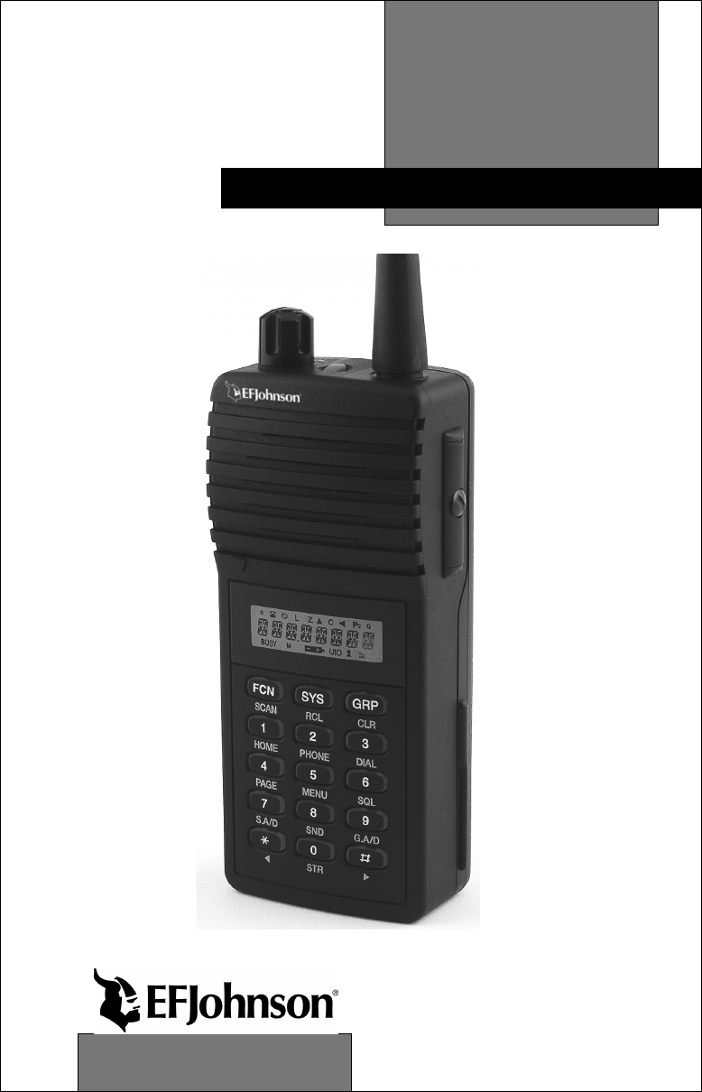
7200 Series
Trunked Portable Radio
OPERATING
PRELIMINARY

LAND MOBILE PRODUCT WARRANTY - The manufacturer’s
warranty statement for this product is available from your product
supplier or from EFJohnson, 299 Johnson Avenue, Box 1249,
Waseca, MN 56093-0514. Phone (507) 835-6222.
Copyright© 2000 by the E.F. Johnson Company
The E.F. Johnson Company, which was founded in 1923,
provides wireless communication systems solutions for public
safety, government, and commercial customers. The company
designs, manufactures, and markets conventional and trunked radio
systems, mobile and portable subscriber radios, repeaters, and
Project 25 digital radio products. E.F. Johnson is a wholly owned
subsidiary of Transcrypt International, Inc.
Viking Head/EFJohnson logo, LTR®, LTR-Net™, and Call Guard®
are trademarks of the E.F. Johnson Company. All other company
and/or product names used in this manual are trademarks and/or
registered trademarks of their respective manufacturer.

SAFETY INFORMATION
4
SAFETY INFORMATION
The FCC has adopted a safety standard for human exposure to RF energy.
Proper operation of this radio under normal conditions results in user
exposure to RF energy below the Occupational Safety and Health Act and
Federal Communication Commission limits.
TO COMPLY WITH FCC R.F. EXPOSURE REQUIREMENTS
Minimum Safe Distance: 2.5 cm (1.0 in)
ANTENNA MOUNTING - Antenna as supplied by manufacturer must
not be placed at a location such that any person or persons can come
closer than the above-indicated mimimum safe distance to the antenna
(2.5 cm).
ANTENNA SUBSTITUTION - Do not substitute any antenna for the
one supplied by manufacturer. You may be exposing person(s) to harmful
radiation. Contact supplier or manufacturer for further instructions.
WARNING
Maintain separation distance from antenna of 2.5 cm (1.0 in) or more.
DO NOT allow the antenna to touch or to come in very close prox-
imity with the eyes, face, or any exposed body parts while the radio is
transmitting.
DO NOT operate the radio in explosive or flammable atmospheres.
The transmitted radio energy could trigger blasting caps or cause an
explosion.
DO NOT operate the radio without the proper antenna installed.
DO NOT allow children to operate or play with this transceiver.

SAFETY INFORMATION
5
DO NOT dispose of the nickel metal-hydride battery pack used by this
radio in fire because it can explode. Dispose of it in accordance with
local regulations. Also, do not short the terminals because it may
become very hot.
NOTE: The above warning list is not intended to include all hazards
that may be encountered when using this radio.
This device complies with Part 15 of the FCC rules. Operation is
subject to the condition that this device does not cause harmful inter-
ference. In addition, changes or modifications to this equipment not
expressly approved by the E.F. Johnson Company could void the
user’s authority to operate this equipment (FCC rules, 47CFR Part
15.19).
OTHER IMPORTANT OPERATING INFORMATION
Usage in Blasting Areas - To avoid interference with blasting operations,
be sure to turn the transceiver off in areas posted “Blasting Area” or
“Turn Off Two-Way Radio”. Remote controlled RF devices are some-
times used to set off explosives.
Operation in Explosive Atmospheres - Turn the transceiver off when in
an area with a potentially explosive atmosphere. Although rare, the trans-
ceiver could generate a spark or a hot surface that could cause an explo-
sion or fire resulting in bodily injury or even death.
Operation in Flammable Atmospheres - Areas with potentially flam-
mable atmospheres are usually, but not always, clearly posted. These
areas may include fueling areas such as gas stations, fuel or chemical
storage and transfer stations, below deck on boats, and areas where the air
contains flammable chemicals or particles such as grain dust or metal
powders. Do not use or transport the transceiver in any atmosphere or
compartment potentially containing flammable gas, liquids, or
explosives.

TABLE OF CONTENTS
6
TABLE OF CONTENTS
SAFETY INFORMATION . . . . . . . . . . . . . . . . . . . . . . . . . . . . . . . . . . 2
IMPORTANT OPERATING INFORMATION . . . . . . . . . . . . . . . . . . 4
QUICK REFERENCE GUIDE . . . . . . . . . . . . . . . . . . . . . . . . . . . . . . . 9
FEATURES . . . . . . . . . . . . . . . . . . . . . . . . . . . . . . . . . . . . . . . . . . . . . 10
General Features . . . . . . . . . . . . . . . . . . . . . . . . . . . . . . . . . . . . . . . . 10
LTR-Net Features . . . . . . . . . . . . . . . . . . . . . . . . . . . . . . . . . . . . . . . 10
LTR Features . . . . . . . . . . . . . . . . . . . . . . . . . . . . . . . . . . . . . . . . . . 10
Conventional Features . . . . . . . . . . . . . . . . . . . . . . . . . . . . . . . . . . . 10
CONTROLS AND DISPLAY. . . . . . . . . . . . . . . . . . . . . . . . . . . . . . . 11
Top Panel Controls. . . . . . . . . . . . . . . . . . . . . . . . . . . . . . . . . . . . . . 11
Side Controls . . . . . . . . . . . . . . . . . . . . . . . . . . . . . . . . . . . . . . . . . . 12
Display . . . . . . . . . . . . . . . . . . . . . . . . . . . . . . . . . . . . . . . . . . . . . . . 13
Front Panel Keys . . . . . . . . . . . . . . . . . . . . . . . . . . . . . . . . . . . . . . . 15
BASIC OPERATION . . . . . . . . . . . . . . . . . . . . . . . . . . . . . . . . . . . . . 20
Power-Up Sequence . . . . . . . . . . . . . . . . . . . . . . . . . . . . . . . . . . . . . 20
Backlight Operation . . . . . . . . . . . . . . . . . . . . . . . . . . . . . . . . . . . . . 20
Setting Volume Levels . . . . . . . . . . . . . . . . . . . . . . . . . . . . . . . . . . . 20
System/Group Display Mode . . . . . . . . . . . . . . . . . . . . . . . . . . . . . . 20
System and Group Select . . . . . . . . . . . . . . . . . . . . . . . . . . . . . . . . . 21
Keypad Disable . . . . . . . . . . . . . . . . . . . . . . . . . . . . . . . . . . . . . . . . 22
Transceiver Lock . . . . . . . . . . . . . . . . . . . . . . . . . . . . . . . . . . . . . . . 22
Low Battery Indication. . . . . . . . . . . . . . . . . . . . . . . . . . . . . . . . . . . 23
Option Switches . . . . . . . . . . . . . . . . . . . . . . . . . . . . . . . . . . . . . . . . 23
LTR-Net, LTR, and Conventional Operation. . . . . . . . . . . . . . . . . . 23
GENERAL FEATURES . . . . . . . . . . . . . . . . . . . . . . . . . . . . . . . . . . . 25
Bank Select. . . . . . . . . . . . . . . . . . . . . . . . . . . . . . . . . . . . . . . . . . . . 25
Call Indicator . . . . . . . . . . . . . . . . . . . . . . . . . . . . . . . . . . . . . . . . . . 25
Emergency Switch . . . . . . . . . . . . . . . . . . . . . . . . . . . . . . . . . . . . . . 26
Encryption . . . . . . . . . . . . . . . . . . . . . . . . . . . . . . . . . . . . . . . . . . . . 26
Home System/Group Select . . . . . . . . . . . . . . . . . . . . . . . . . . . . . . . 27
Option Select . . . . . . . . . . . . . . . . . . . . . . . . . . . . . . . . . . . . . . . . . . 27
Power Select . . . . . . . . . . . . . . . . . . . . . . . . . . . . . . . . . . . . . . . . . . . 27
Proceed (Clear-To-Talk) Tone . . . . . . . . . . . . . . . . . . . . . . . . . . . . . 27
Receive-Only Groups . . . . . . . . . . . . . . . . . . . . . . . . . . . . . . . . . . . . 28
Stealth Mode. . . . . . . . . . . . . . . . . . . . . . . . . . . . . . . . . . . . . . . . . . . 28
Time-Out Timer . . . . . . . . . . . . . . . . . . . . . . . . . . . . . . . . . . . . . . . . 28
Tone Select . . . . . . . . . . . . . . . . . . . . . . . . . . . . . . . . . . . . . . . . . . . . 29

TABLE OF CONTENTS
7
STANDARD GROUP CALLS. . . . . . . . . . . . . . . . . . . . . . . . . . . . . . 29
General . . . . . . . . . . . . . . . . . . . . . . . . . . . . . . . . . . . . . . . . . . . . . . . 29
Placing a Standard Group Call . . . . . . . . . . . . . . . . . . . . . . . . . . . . . 29
Receiving a Standard Group Call . . . . . . . . . . . . . . . . . . . . . . . . . . . 31
TELEPHONE CALLS. . . . . . . . . . . . . . . . . . . . . . . . . . . . . . . . . . . . . 31
General . . . . . . . . . . . . . . . . . . . . . . . . . . . . . . . . . . . . . . . . . . . . . . . 31
Placing Telephone Calls . . . . . . . . . . . . . . . . . . . . . . . . . . . . . . . . . . 31
Receiving a Telephone Call . . . . . . . . . . . . . . . . . . . . . . . . . . . . . . . 33
Landside-Originate Telephone Calls . . . . . . . . . . . . . . . . . . . . . . . . 33
LTR-NET AUXILIARY CALLS . . . . . . . . . . . . . . . . . . . . . . . . . . . . . 33
General . . . . . . . . . . . . . . . . . . . . . . . . . . . . . . . . . . . . . . . . . . . . . . . 33
Placing LTR-Net Auxiliary Calls. . . . . . . . . . . . . . . . . . . . . . . . . . . 34
Receiving Auxiliary Calls . . . . . . . . . . . . . . . . . . . . . . . . . . . . . . . . 35
OPTION SWITCHES AND MENU MODE . . . . . . . . . . . . . . . . . . . 35
Option Switches . . . . . . . . . . . . . . . . . . . . . . . . . . . . . . . . . . . . . . . . 35
Menu Mode . . . . . . . . . . . . . . . . . . . . . . . . . . . . . . . . . . . . . . . . . . . 36
DIAL MODE. . . . . . . . . . . . . . . . . . . . . . . . . . . . . . . . . . . . . . . . . . . . . 38
Introduction . . . . . . . . . . . . . . . . . . . . . . . . . . . . . . . . . . . . . . . . . . . 38
Selecting Dial Mode . . . . . . . . . . . . . . . . . . . . . . . . . . . . . . . . . . . . . 38
Dialing a Number . . . . . . . . . . . . . . . . . . . . . . . . . . . . . . . . . . . . . . . 39
Sending the Number . . . . . . . . . . . . . . . . . . . . . . . . . . . . . . . . . . . . . 39
Storing Numbers in Memory . . . . . . . . . . . . . . . . . . . . . . . . . . . . . . 39
Recalling Numbers From Memory. . . . . . . . . . . . . . . . . . . . . . . . . . 40
Exiting Dial Mode . . . . . . . . . . . . . . . . . . . . . . . . . . . . . . . . . . . . . . 40
Placing Calls Without Selecting Dial Mode. . . . . . . . . . . . . . . . . . . 40
SYSTEM AND GROUP SCANNING. . . . . . . . . . . . . . . . . . . . . . . . 41
General . . . . . . . . . . . . . . . . . . . . . . . . . . . . . . . . . . . . . . . . . . . . . . . 41
Scan List Programming . . . . . . . . . . . . . . . . . . . . . . . . . . . . . . . . . . 43
Scan Delay and Continue Timers . . . . . . . . . . . . . . . . . . . . . . . . . . . 44
Transmitting In The Scan Mode. . . . . . . . . . . . . . . . . . . . . . . . . . . . 45
LTR-NET AND LTR FEATURES. . . . . . . . . . . . . . . . . . . . . . . . . . . 46
Transmit Inhibit . . . . . . . . . . . . . . . . . . . . . . . . . . . . . . . . . . . . . . . . 46
Priority Calls. . . . . . . . . . . . . . . . . . . . . . . . . . . . . . . . . . . . . . . . . . . 46
LTR-NET FEATURES . . . . . . . . . . . . . . . . . . . . . . . . . . . . . . . . . . . . 47
LTR-Net Standard Calls . . . . . . . . . . . . . . . . . . . . . . . . . . . . . . . . . . 47
LTR-Net Special Calls . . . . . . . . . . . . . . . . . . . . . . . . . . . . . . . . . . . 47
Busy Queuing . . . . . . . . . . . . . . . . . . . . . . . . . . . . . . . . . . . . . . . . . . 47
Roaming . . . . . . . . . . . . . . . . . . . . . . . . . . . . . . . . . . . . . . . . . . . . . . 48

TABLE OF CONTENTS
8
LTR FEATURES . . . . . . . . . . . . . . . . . . . . . . . . . . . . . . . . . . . . . . . . . 49
Standard Group Calls . . . . . . . . . . . . . . . . . . . . . . . . . . . . . . . . . . . . 49
Telephone Calls . . . . . . . . . . . . . . . . . . . . . . . . . . . . . . . . . . . . . . . . 49
CONVENTIONAL FEATURES. . . . . . . . . . . . . . . . . . . . . . . . . . . . . 49
Squelch Adjust . . . . . . . . . . . . . . . . . . . . . . . . . . . . . . . . . . . . . . . . . 49
Monitoring Before Transmitting . . . . . . . . . . . . . . . . . . . . . . . . . . . 50
Transmit Disable On Busy . . . . . . . . . . . . . . . . . . . . . . . . . . . . . . . . 51
Talk-Around . . . . . . . . . . . . . . . . . . . . . . . . . . . . . . . . . . . . . . . . . . . 52
Call Guard Squelch. . . . . . . . . . . . . . . . . . . . . . . . . . . . . . . . . . . . . . 52
MISCELLANEOUS. . . . . . . . . . . . . . . . . . . . . . . . . . . . . . . . . . . . . . . 53
Supervisory Tones . . . . . . . . . . . . . . . . . . . . . . . . . . . . . . . . . . . . . . 53
LTR-Net Special Call Tones . . . . . . . . . . . . . . . . . . . . . . . . . . . . . . 54
LTR Telephone Call Tones . . . . . . . . . . . . . . . . . . . . . . . . . . . . . . . 55
Display Messages . . . . . . . . . . . . . . . . . . . . . . . . . . . . . . . . . . . . . . . 55
Menu Mode Messages . . . . . . . . . . . . . . . . . . . . . . . . . . . . . . . . . . . 57
Rechargeable Battery Pack. . . . . . . . . . . . . . . . . . . . . . . . . . . . . . . . 58
Speaking Into Microphone . . . . . . . . . . . . . . . . . . . . . . . . . . . . . . . . 60
Operation At Extended Range . . . . . . . . . . . . . . . . . . . . . . . . . . . . . 60
Licensing . . . . . . . . . . . . . . . . . . . . . . . . . . . . . . . . . . . . . . . . . . . . . 60
Transceiver Service . . . . . . . . . . . . . . . . . . . . . . . . . . . . . . . . . . . . . 60
INDEX . . . . . . . . . . . . . . . . . . . . . . . . . . . . . . . . . . . . . . . . . . . . . . . . . . 61
QUICK REFERENCE GUIDE
9
QUICK REFERENCE GUIDE
Change system number - Press SYS or or SYS (1-99) [pg 21]
Change group number - Press GRP or or GRP (1-99) [pg 21]
System scan on/off - FCN SCAN ( indicates scanning is enabled) [pg 41]
Change scan list status of displayed system - FCN S.A/D ( indicates that
the system is in the scan list and scanned normally) [pg 43]
Change scan list status of displayed group - FCN G.A/D ( indicates that the
group is in the scan list and scanned normally) [pg 43]
Change between alpha and numeric display modes - FCN STR [pg 20]
Display home or last active system/group - FCN HOME [pg 27]
Select/Exit Menu Mode - FCN MENU [pg 36]
Lock/Unlock Keypad - FCN ( indicates locked keypad) [pg 22]
Adjust Squelch (conventional only) - FCN SQL then and [pg 49]
NUMBER DIALING
Select dial mode without changing system/group - FCN DIAL [pg 38]
Select dial mode and telephone system/group) - FCN PHONE [pg 38]
Transmit number in display - FCN SND [pg 39]
Erase last number in display - CLR [pg 39]
Erase entire number in display - RCL CLR [pg 39]
Display overflow digits - FCN [pg 39]
Enter a pause - FCN [pg 39]
Store a number in memory - Enter no., then FCN STR (0-9) [pg 39]
Display numbers in memory - RCL (hold down to repeat) [pg 40]
Recall number from a memory location - FCN RCL (0-9) [pg 40]
Recall last number dialed - FCN RCL [pg 40]
Recall last number dialed from memory - FCN RCL [pg 40]
Exit dial mode and terminate call - FCN PHON [pg 40]
Exit dial mode without terminating call - FCN DIAL [pg 40]
BUSY
M
G
S
UID Tx
P
2
C
L
O
System
Scan List
Phone
Group
Group Scan
List
Scan Call
8-Character
Alphanumeric
MonitorEncryption
Keypad
Dial
Mode
Low
Power
Stealth
Mode
Priority
Tr a n s mi t t e r
Keyed
Lock
UID/Aux
Group
Low
Battery
Unread
Message
Conv Ch
Busy
Display
S
G
For more information on a function, refer to the page number in brackets [xx].

FEATURES
10
FEATURES
General Features
•Up to approximately 99 systems with up to 99 groups per system
•Up to 16 banks selectable
•LTR-Net™, LTR®, and conventional operating modes
•Unique 8-character system identification tags
•System and group scan
•User programmable system and group scan lists
•Menu mode to select various functions
•User selectable high and low power output
•Three programmable option switches
•Call progress tones
•Call indicator
•Receive-only groups
•Companding (optional)
•Encryption (optional)
LTR-Net Features
•Roaming (automatic locality search)
•Standard group (mobile-to-mobile) calls
•Special calls including telephone, unique ID, and directed group
•Busy queuing of special calls by radio system
•Transmit inhibit
•Receive priority calls
LTR Features
•Standard group and telephone calls
•Transmit inhibit
•Receive priority calls
Conventional Features
•Busy indicator
•Talk-around
•User-adjustable squelch level
•Monitor mode
•Call Guard® squelch control
•Transmit disable on busy
NOTE: System operator programming determines the availability of many of the
preceding features.
CONTROLS AND DISPLAY
11
CONTROLS AND DISPLAY
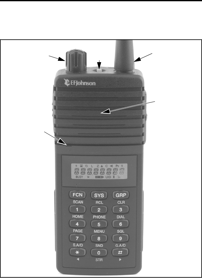
Top Panel Controls
On-Off Volume - Turning this knob clockwise turns power on and sets
the volume level. Turning it counterclockwise to the detent turns power
off. Power is on when information appears in the display. For more infor-
mation on setting the volume, refer to page 20.
Antenna Jack
On-Off/Volume
Microphone
Speaker
Option
Switch
CONTROLS AND DISPLAY
12
Option Switch 1 - This switch can be system operator programmed to
control a specific function (see page 35).
Antenna Jack - Connection point for the antenna.
Battery Release Button (Not shown) - This button is located on the
bottom end of the transceiver, and it is pressed to release the battery so
that it can slide downward and removed from the radio.
NOTE: Turn transceiver power off before removing or installing the
battery.
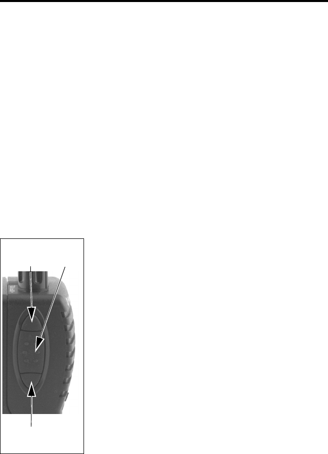
Side Controls
Option Switch 2 - This switch can be system oper-
ator programmed to control a specific function (see
page 35).
PTT (Push-To-Talk) - Keys the transmitter so that a
message can be transmitted. The “Tx” icon in the
display indicates when the transmitter is keyed.
Option Switch 3 - This switch can be system oper-
ator programmed to control a specific function (see
page 35).
Accessory Connector (not shown) - This connector
is on the other side of the transceiver, and it is used
for connecting optional accessories such as a speaker-
microphone.
Option
Switch 2
PTT
Switch
Option
Switch 3
CONTROLS AND DISPLAY
13
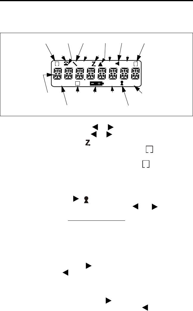
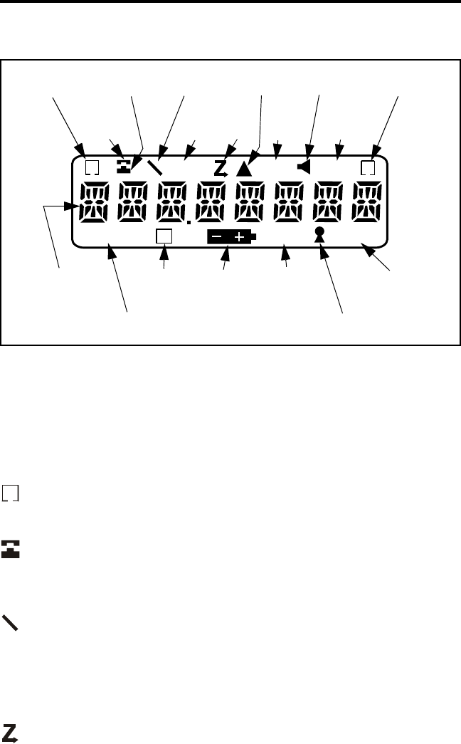
Display
8-Character Alphanumeric Display - This area of the display indicates
the selected system/group (see “System/Group Display Mode” on
page 20), the dialed number (see “Dial Mode” on page 38), error condi-
tions, and other information.
- Indicates that the displayed system is in the scan list and scanned
normally (see “Scan List Programming” on page 43).
- The base portion of this icon is displayed when the displayed group
is programmed for telephone calls. The top portion (receiver) is displayed
when the dial mode is selected (see page 38).
- Indicates that the optional encryption feature is enabled (see
page 26).
L - Indicates that the low-power mode is selected by the menu mode or a
low-battery condition (see page 27).
- Indicates that the scan mode is selected (see page 41).
BUSY M
G
S
UID Tx
P2
C
L
O
System
Scan List
Phone
Group
Group Scan
List
Scan Call
8-Character
Alphanumeric
Monitor
Encryption
Keypad
Dial
Mode
Low
Power
Stealth
Mode
Priority
Transmitter
Keyed
Lock
UID/Aux
Group
Low
Battery
Unread
Message
Conv Ch
Busy
Display
S
O

CONTROLS AND DISPLAY
14
- Indicates that the stealth mode is selected (see page 28) or that an
optional accessory is enabled (see page 27).
C - Indicates that a call has been received on a group programmed for a
call indicator (see page 25). Press any key to turn this indication off.
- Indicates that the conventional monitor mode has been enabled by
the Monitor option switch (see page 50).
- “P” indicates that the displayed group is an LTR-Net/LTR priority
1 group, and “P2” indicates that it is a priority 2 group (see page 46).
- Indicates that the displayed group is in the scan list and scanned
normally (see page 43).
BUSY - Indicates that the selected conventional channel is currently busy
with voice or other traffic.
- Indicates a low battery condition. The battery should be
recharged or replaced as soon as practical (see page 23).
UID - Indicates that the displayed group is programmed for an LTR-Net
Unique ID or Directed Group call (see page 47).
- Indicates that the keypad has been locked by pressing FCN
(page 22).
Tx - Indicates that the transmitter is keyed (push-to-talk switch pressed).
P
2
G
CONTROLS AND DISPLAY
15
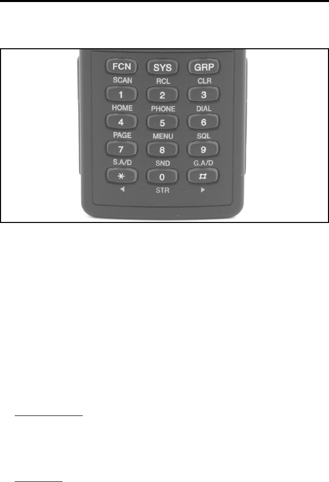
Front Panel Keys
Most front panel keys have two or more functions. The function on
the key is usually selected by simply pressing the key, and the function
under the key is usually selected by first pressing another key such as the
FCN key. In addition, some key functions may be available in the stan-
dard mode and others in the dial mode (see page 38). Holding the key
down causes repeating when applicable. The front panel keys operate as
follows:
FCN (SCAN)
Standard Mode
FCN - Enables the alternate function of the next key that is pressed.
This alternate function is active for 2 seconds or until another key
is pressed.
FCN SCAN - Turns scanning on and off.
Dial Mode
FCN - Selects the alternate function of various keys as described in
the following information.

CONTROLS AND DISPLAY
16
SYS (RCL)
Standard Mode
SYS - Selects the next higher system.
SYS - Selects the next lower system.
SYS (xx) - Directly selects specified system.
FCN SYS - Momentarily displays the revert (selected) system if it
is not already being displayed.
Dial Mode
RCL - Scrolls through the numbers programmed in memory.
FCN RCL (0-9) - Recalls the number stored in the specified
memory location.
FCN RCL - Recalls the last number dialed from memory.
FCN RCL - Recalls the last number dialed.
GRP (CLR)
Standard Mode
The GRP key functions the same as “SYS” just described to change
or display the selected group.
Dial Mode
CLR - Erases the last digit in the display.
FCN CLR - Erases the entire number in the display.
1 (HOME)
Standard Mode
FCN HOME - Selects the preprogrammed home system/group.
1 - Pressing this key with the PTT switch pressed transmits the “1”
digit.
Dial Mode
1 - Dials the “1” digit.
2 (PHONE)
Standard Mode
FCN PHONE - Selects the dial mode and a telephone group in the
current system.
2 - Pressing this key with the PTT switch pressed transmits the “2”
digit.

CONTROLS AND DISPLAY
17
Dial Mode
2 - Dials the “2” digit.
FCN PHONE - Exits the dial mode and sends the call termination
code.
3 (DIAL)
Standard Mode
FCN DIAL - Selects the dial mode without changing the currently
selected group.
3 - Pressing this key with the PTT switch pressed transmits the “3”
digit.
Dial Mode
3 - Dials the “3” digit.
FCN DIAL - Exits the dial mode without sending the call
termination code.
4 (PAGE)
Standard Mode
FCN PAGE - The page function is currently not available.
4 - Pressing this key with the PTT switch pressed transmits the “4”
digit.
Dial Mode
4 - Dials the “4” digit.
5 (MENU)
Standard Mode
FCN MENU - Selects the menu mode.
5 - Pressing this key with the PTT switch pressed transmits the “5”
digit.
Dial Mode
5 - Dials the “5” digit.
6 (SQL)
Standard Mode
FCN SQL - Selects the squelch adjust mode for conventional chan-
nels.
6 - Pressing this key with the PTT switch pressed transmits the “6”
digit.

CONTROLS AND DISPLAY
18
Dial Mode
6 - Dials the “6” digit.
7 (S.A/D)
Standard Mode
FCN S.A/D - Changes the scan list status of the currently displayed
system. The system is in the scan list and scanned normally if
“ ” is displayed when not scanning.
7 - Pressing this key with the PTT switch pressed transmits the “7”
digit.
Dial Mode
7 - Dials the “7” digit.
8 (SEND)
Standard Mode
8 - Pressing this key with the PTT switch pressed transmits the “8”
digit.
Dial Mode
8 - Dials the “8” digit.
FCN SEND - Automatically accesses the radio system and trans-
mits the number in the display.
9 (G.A/D)
Standard Mode
FCN G.A/D - Changes the scan list status of the currently displayed
group. The group is in the scan list and scanned normally if “ ”
is displayed when not scanning.
9 - Pressing this key with the PTT switch pressed transmits the “9”
digit.
Dial Mode
9 - Dials the “9” digit.
0 (STR)
Standard Mode
FCN STR - Changes between the numeric and alpha display
modes.
0 - Pressing this key with the PTT switch pressed transmits the “0”
digit.
S
G
CONTROLS AND DISPLAY
19
Dial Mode
0 - Dials the “0” digit.
FCN STR (0-9) - Stores the displayed number in the specified
memory location.
()
Standard Mode
- Pressing this key with the PTT switch pressed transmits the
“ ” digit.
SYS - Selects the next lower system (see preceding “SYS” key
description).
GRP - Selects the next lower group (see preceding “GRP” key
description).
Dial Mode
- Dials the “ ” digit.
FCN - Enters a pause when dialing a telephone number.
FCN RCL - Recalls the last number dialed from memory.
()
Standard Mode
FCN - Enables and disables the keypad lock feature.
- Pressing this key with the PTT switch pressed transmits the “ ”
digit.
SYS - Selects the next higher system (see preceding “SYS” key
description).
GRP - Selects the next higher group (see preceding “GRP” key
description).
Dial Mode
- Dials the “ ” digit.
FCN - Displays the overflow digits for a short time.
FCN RCL - Recalls the last number dialed.
#
##
##

BASIC OPERATION
20
BASIC OPERATION
Power-Up Sequence
When power is turned on using the top panel on-off/volume control,
the backlight turns on, all segments and icons in the display are momen-
tarily enabled, and the last seven digits of the transceiver part number are
very briefly displayed. A beep then sounds (if tones are enabled) and the
transceiver is operational.
Backlight Operation
The display and keypad backlight automatically turns on for 3
seconds whenever any key is pressed.
Setting Volume Levels
The relative volume level can be determined by noting the position
of the index on the volume knob. You may also be able to enable a tone
or background noise for use in setting the volume as follows:
•If key press tones are enabled, a short tone sounds whenever any key is
pressed.
•If a conventional system is selected and the monitor option switch is
programmed (see page 50), press this switch and if someone is talking
on the channel, voice is heard. If no one is talking, the squelch can be
adjusted as described on page 49 and noise is heard. It is not possible to
manually unsquelch the transceiver when an LTR-Net or LTR system
is selected.
System/Group Display Mode
Two system/group display modes can be selected. One is a numeric
format and the other is an alpha tag format. To switch between these
modes, press FCN STR. Turning power off does not change the selected
mode. These modes operate as follows:
BASIC OPERATION
21
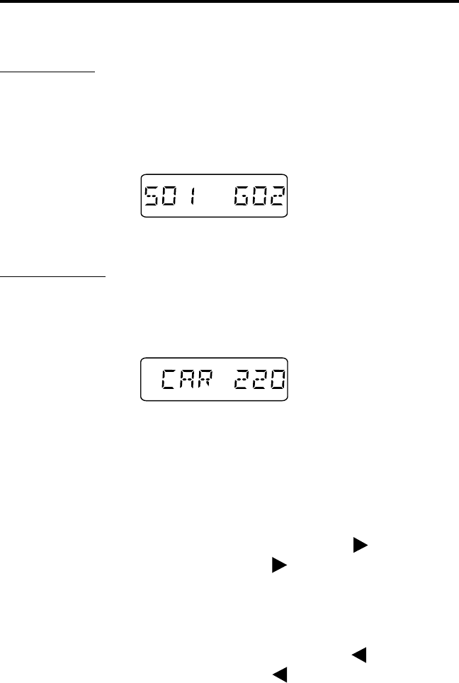
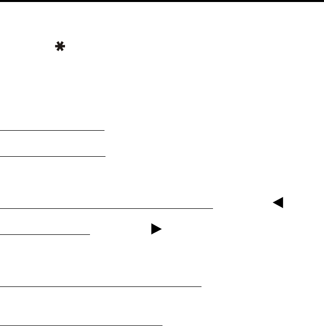
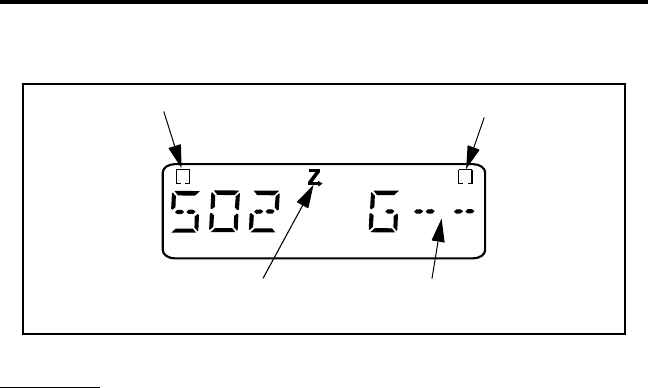
Numeric Mode - The system and group numbers are displayed as “Sxx
Gxx” and the group alpha tag is not displayed. For example, System 1
and Group 2 are displayed as follows. When only group scanning is
occurring, the group number is replaced by dashes and the system
number continues to be displayed (see page 41).
Numeric Display Mode
Alpha Tag Mode - The group alpha tag is displayed and the system and
group numbers are not displayed. For example, the “CAR 220” system is
displayed as follows. There is no special group scan indication when only
group scanning is occurring.
Alpha Tag Display Mode
System and Group Select
Systems and groups are selected by the keypad SYS and GRP keys
and one or more other keys as follows:
•To increase the selected system, press SYS and then . Likewise, to
increase the selected group, press GRP . Holding the key down
causes the function to repeat. After the highest system or group is
selected, a tone sounds and wrap-around to the lowest system or group
occurs.
•To decrease the selected system, press SYS and then . Likewise, to
decrease the selected group, press GRP . Holding the key down
causes the function to repeat. After the lowest system or group is
selected, a tone sounds and wrap-around to the highest system or group
occurs.

BASIC OPERATION
22
•To directly select a system or group number, press SYS or GRP and
then the number of the desired system or group. For example, to select
Group 9, press GRP, 0, 9 (two digits must also be entered for numbers
0-9).
Keypad Disable
Occasionally, the front panel keys may be accidentally pressed, for
example, if you carry the transceiver on your belt and it brushes against
an object. To prevent this from happening, the front panel keys can be
disabled by the keypad lock feature. To lock and unlock the keypad, press
FCN . The locked condition is indicated by the icon and LOCK in
the display. If a key is pressed with the keypad locked, all that happens is
“LOCKED” is displayed. The top and side panel controls remain func-
tional with this feature selected, and turning power off and then on again
does not unlock the keypad.
Transceiver Lock
The transceiver can be locked to prevent unauthorized usage. To
lock the transceiver, press FCN and “PASSWORD” is then displayed
to indicate that a four-digit unlock password must be entered. This pass-
word can be any four-digit number except “0000”. The password must be
re-entered to confirm it and the transceiver is then locked as indicated by
“LOCKED” in the display.
When the transceiver is in the lock mode, calls cannot be received or
transmitted. In addition, all controls except FCN and the on-off/
volume control are disabled. To unlock the transceiver, the four-digit
password must be re-entered. The transceiver then remains unlocked until
it is locked again by repeating this sequence.
Since the password is not preprogrammed, a different password can
be entered each time this feature is used. If the password is forgotten, the
transceiver must be returned to your system operator for reprogramming
to make it operational again.

BASIC OPERATION
23
Low Battery Indication
When the battery voltage drops to the point where recharging is
required, the icon is indicated in the bottom part of the display,
and a beep sounds when this indication initially appears and when the
push-to-talk switch is released (if the key press tone is enabled). The
battery should be recharged as soon as possible after this indication
appears (see page 58).
The low-battery indication is turned off by turning power off and
then on again. Current settings of switches and other parameters are
saved in memory during a low-battery condition, and low transmit power
is automatically selected (indicated by “L” in display). If the battery
voltage drops to the point where the transceiver no longer operates, all
segments in the display are enabled.
Option Switches
This transceiver has three option switches that can be programmed
by your system operator to control various functions (see table on
page 36). They are the push-button switch on the top panel and the switch
immediately above and the switch immediately below the PTT switch on
the side panel (see page 12).
LTR-Net, LTR, and Conventional Operation
Introduction
Each selectable system can be programmed for LTR-Net, LTR, or
conventional operation. The type of operation that is programmed is
determined by the radio equipment being used by your system operator.
There are a few differences in operation that are described in the
following information and also noted elsewhere in this manual as
required.

BASIC OPERATION
24
LTR-Net and LTR Operation
The LTR-Net and LTR modes provide automatic channel selection
and monitoring before transmitting. Special tones and display messages
indicate busy and out-of-range conditions, and telephone calls can be
placed almost as conveniently as with your home
telephone.
Selecting a system selects a collection of up to 99 groups, and
selecting one of these groups selects an ID code which determines the
type of call (standard group, telephone, or special) and the specific
mobile or mobiles is being called (if applicable) and what calls are
received. In addition, higher priority calls may be received (see page 46).
The LTR-Net operating mode provides the most operating features.
Exclusive LTR-Net features include roaming and Unique ID and Directed
Group calls. When operating in LTR-Net sites, calls may be made to
mobiles in other sites as well as the current site. LTR-Net and LTR
features are described starting on page 46.
Conventional Operation
In the conventional mode, selecting a system selects a conventional
channel, and selecting a group selects the special Call Guard squelch
coding (if used) and other unique parameters on that channel such as call
indicator operation. The Call Guard coding determines the mobile or group
of mobiles being called and also the mobiles from which calls are received
(see “Call Guard Squelch” on page 52).
In the conventional mode, a busy condition is detected automatically
if the Transmit Disable On Busy feature is used. Otherwise, it must be
detected manually as described in “Monitoring Before Transmitting” on
page 50. Unsuccessful access conditions cannot be detected with conven-
tional signaling, so are not indicated by special tones or display
messages. Refer to “Operation At Extended Range” on page 60 for infor-
mation on how to determine if an out-of-range condition may exist.

GENERAL FEATURES
25
GENERAL FEATURES
Bank Select
A bank is a collection of selectable systems that have been set up for
a specific application. For example, one bank could be programmed for
operation in Minneapolis and another for operation in Milwaukee. Up to
sixteen banks can be programmed, and each bank is identified by a
unique alpha tag.
Banks are selected by the BANK SEL menu parameter or BANK
option switch. In the menu mode select the “BANK SEL” parameter and
then the desired bank (refer to page 36 for more menu mode informa-
tion). If using the Bank option switch, press the and keys to
select the desired bank. If neither the menu parameter nor the option
switch is available, banks are not selectable.
Call Indicator
The call indicator is “C” in the upper part of the display (see
following illustration). The purpose of this indication is to show that a
call was received while you were away from the radio. Individual groups
can be programmed for this feature and it then turns on when a call is
received on one of those groups.
This indicator is turned off by pressing any button or cycling power.
If scanning and the “Last Received” configuration is programmed (see
“Transmitting In The Scan Mode” on page 45), the system and group of
the last call are displayed. Otherwise, the currently selected system/group
is displayed.
C
Call
Indicator

GENERAL FEATURES
26
Emergency Switch
If the EMER option switch is programmed (see page 35), it is used
to quickly select the emergency system/group that has been programmed
in the current bank. The emergency call must then be manually trans-
mitted by pressing the PTT switch (automatic transmissions do not
occur). Scanning continues if it is enabled, and calls are received
normally on other systems and groups if applicable.
Encryption
Encryption is an optional feature that prevents conversations from
being monitored by casual eavesdropping and analog scanners. It does
this by encrypting your voice so that it can be understood only by
someone using a transceiver equipped with a similar encryption device.
Encryption is enabled and disabled by the ENCRYPT menu param-
eter or Encryption option switch (see page 35). If equipped with encryp-
tion and neither the menu parameter nor the option switch is available,
encryption is always enabled. When encryption is enabled, is indi-
cated in the display as shown below.
To transmit an encrypted call, encryption must be enabled as just
described and the selected group must be programmed for encryption.
Encrypted calls are always received regardless of the currently selected
encryption mode and group programming (if the radio is equipped with
encryption). When transmitting an encrypted call, wait approximately 1
second before speaking. This gives the receiving transceiver time to
establish synchronization which ensures that all of the first word is
received. If the proceed tone is used and an encrypted call is transmitted,
two beeps instead of one sound and the tone is automatically delayed for
the required time.
O
Encryption
Indicator

GENERAL FEATURES
27
Home System/Group Select
To select the preprogrammed Home system/group, simply press the
FCN HOME. The Home system/group is then displayed and it becomes
the selected system/group. If no home system/group has been
programmed, this function is not available. A different home system/
group can be programmed for each bank.
Option Select
The Auxiliary option switch or OPTION menu parameter can be
used to control an accessory that may have been installed by your system
operator. The enabled condition is indicated by in the display.
Power Select
High and low transmit power output is selectable if the “TX
POWER” menu parameter is available. Select either “LO POWER” or
“HI POWER” as described on page 36. When low power output is
selected manually or automatically, “L” is indicated in the display (see
page 13). Turning power off and then on again does not change the
selected power output level. Selecting low power may increase battery
life and decrease range, and selecting high power may cause the opposite
to occur. The low power mode is automatically selected during a low
battery condition (see page 23).
Proceed (Clear-To-Talk) Tone
This is a short tone that sounds shortly after the PTT switch is
pressed to indicate that the radio system has been accessed and speaking
can begin. This tone can be programmed to be a single or distinctive (3-
beep) tone. With encrypted calls, a special double beep sounds.
This tone always sounds with LTR-Net and LTR standard calls if
tones are enabled by the TONES menu parameter (see “Tone Select” on
page 29) or system operator programming. It can also be programmed to

GENERAL FEATURES
28
sound with conventional calls and/or LTR-Net and LTR auxiliary and
telephone calls (first access only).
On LTR-Net and LTR systems, if the radio system is busy when
making a call, the busy tone sounds instead of the proceed tone and
“BUSY” is indicated in the display. If an access attempt is unsuccessful,
such as because of an out-of-range condition, the intercept tone sounds
and “NO ACCES” is indicated in the display. Refer to page 53 for more
information on these conditions.
If the proceed tone is enabled on conventional systems and the
Transmit Disable On Busy feature is used to automatically perform moni-
toring (see page 51), the proceed tone does not sound if the channel is
busy. Otherwise, it sounds even if the channel is busy.
Receive-Only Groups
Any group can be programmed for monitoring only (transmitting
disabled). If the PTT switch is pressed with one of these groups selected,
the intercept tone sounds and “TX DISBL” is displayed.
Stealth Mode
The stealth mode disables all tones and the display backlight so that
they do not reveal you are transmitting or otherwise indicate your pres-
ence. The speaker audio and display remain enabled. The stealth mode
can be selected by the STEALTH menu parameter (see page 35) or it can
be fixed in the on or off mode by dealer programming. There is no special
indication that this mode is selected except that “On” is briefly displayed
when it is selected by the menu parameter.
Time-Out Timer
The time-out timer disables the transmitter if it is keyed continu-
ously for longer than the programmed time. It can be programmed for 0.5
- 5.0 minutes or disabled entirely. If the transmitter is keyed continuously
for longer than the programmed time, the transmitter is disabled,
“TIMEOUT” is indicated in the display and the intercept tone sounds.
The timer and tone are reset by releasing the PTT switch.

STANDARD GROUP CALLS
29
One use of the time-out timer feature is to prevent a repeater from
being kept busy for an extended period by an accidentally keyed trans-
mitter. It can also prevent possible damage to the transmitter caused by
transmitting for an excessively long period.
Tone Select
If the TONES menu parameter is selectable, the tones that sound can
be selected. Otherwise, the tones that sound are fixed by programming.
The following choices are available. Refer to page 36 for more informa-
tion on using the menu mode.
Silent - All tones are disabled.
Keys - Only the key press tones are enabled.
Alerts - All tones except the preceding key press tones are enabled.
All - Both the key press and alert tones are enabled.
STANDARD GROUP CALLS
General
Most calls you make are probably the standard group type described
in this section. These calls are between you and another mobile or control
station. The main difference between these calls and the other types is
that no number is dialed using a keypad. The following procedure applies
to all three types of operation (LTR-Net, LTR, and conventional).
Placing a Standard Group Call
1. Turn transceiver power on and set the volume as described starting on
page 20. With conventional operation, also make sure that the squelch
is properly set as described on page 49.
2. Select the system and group of the mobile being called as described on
page 21.
3. If a conventional call is being placed, monitor the channel manually or
automatically as described on page 50.

STANDARD GROUP CALLS
30
4. Press (and hold) the microphone PTT (push-to-talk) switch to talk and
release it to listen. Operation with LTR-Net, LTR, and conventional
calls is as follows:
LTR-Net and LTR Operation
•If tones are enabled, the proceed tone sounds shortly after the PTT
switch is pressed if the radio system was successfully accessed (see
page 27). If tones are not enabled, no tone sounds when the system
is successfully accessed.
•If the radio system is busy, the busy tone sounds (see page 53) and
“BUSY” is indicated in the display. Additional access attempts as
long as you continue pressing the PTT switch.
•If the radio system could not be accessed because of an out-of-range
condition or some other reason, the intercept tone sounds (see
page 53) and “NO ACCES” is indicated in the display. The PTT
switch must then be released and pressed again to make another
access attempt.
•When responding, busy or no access conditions may also occur the
same as when placing a call because the system is re-accessed for
each transmission with these calls.
Conventional Operation
•If the channel is busy and the Transmit Disable On Busy feature is
programmed (see page 51), “DSBL BSY” is indicated in the display
and the transmitter is disabled. Any channel activity is heard while
the PTT switch is pressed.
•Otherwise, busy and out-of-range conditions are not indicated and
speaking can begin when the PTT switch is pressed (if the channel is
not busy). If the proceed tone is enabled on conventional systems, it
indicates when speaking can begin but does not indicate that the
channel is free or has been successfully accessed.

TELEPHONE CALLS
31
Receiving a Standard Group Call
1. Select or scan the system and group programmed for the call you want
to receive (see page 41 for scan information).
2. When the message is received, the display changes to the system and
group of the call. Press the PTT switch to talk and release it to listen. If
scanning, a response may not automatically occur on the group of the
call. Refer to “Transmitting In The Scan Mode” on page 45 for more
information.
TELEPHONE CALLS
General
NOTE: Telephone calls can be placed and received only if that service is
available to you and your transceiver has been programmed appropri-
ately.
The telephone calling feature allows you to place and receive tele-
phone calls using your transceiver. The following information describes
how these calls are made with LTR-Net and LTR operation. If you can
make telephone calls with conventional operation, the procedure may be
somewhat different and your system operator may provide additional
information. Proceed as follows:
Placing Telephone Calls
1. Turn transceiver power on and set the volume as described starting on
page 20.
2. Select the dial mode and a telephone group as follows. When the dial
mode is selected, the handset portion of the telephone icon is
displayed, and then when a telephone group is selected, the base portion
is displayed.

TELEPHONE CALLS
32
•To select the dial mode and a preprogrammed telephone group, press
FCN PHONE.
•To select the dial mode without changing the selected group, press
FCN DIAL. Then manually select a telephone group if required.
3. Dial the desired number using the keypad or recall it from memory by
pressing FCN RCL and the location number (0-9). Refer to the dial
mode description starting on page 38 for more information.
4. To automatically access the radio system and send the telephone
number, press FCN SND. Landside ringing (or a landside busy condi-
tion) should then be heard.The following conditions may also occur:
•If the radio system is busy or could not be accessed, busy or no
access conditions may be indicated the same as described for stan-
dard group calls on page 30.
•With LTR-Net operation, a short tone sounds to indicate that the
number was accepted by the system.
5. When the other party answers, press the PTT switch and respond. The
PTT switch must be pressed to talk and released to listen the same as
with standard group calls.
6. When the call is finished, it should be terminated and the dial mode
exited. The call is usually terminated by transmitting either the or
characters.
To automatically send these characters and exit the dial mode, press
FCN PHONE. To exit the dial mode without sending these characters,
press FCN DIAL. Termination is indicated by three beeps. Terminating
the call in this manner prevents extra billing that may occur while the
system automatically detects the end of the call.
#
#

LTR-NET AUXILIARY CALLS
33
Receiving a Telephone Call
1. Select or scan the system and group programmed for telephone calls.
When a telephone group is selected, the base portion of the tele-
phone icon is displayed.
2. When “ringing” is heard, press the PTT switch and respond. The PTT
switch must be pressed to talk and released to listen the same as with
standard calls.
3. When the call is finished, it should be terminated as in step 6 of the
preceding section.
Landside-Originate Telephone Calls
If telephone calls can be placed, it is usually possible to receive tele-
phone calls from a landside telephone. With some radio systems, each
mobile is assigned a unique telephone number so that it can be dialed
directly. With others, the number of the radio system is dialed and then
when a tone sounds, the number specifying the mobile being called is
dialed. The mobile user hears “ringing” when a telephone call is received.
Contact your system operator for the number to dial and other informa-
tion on how to place these calls.
LTR-NET AUXILIARY CALLS
General
The LTR-Net auxiliary calls are Unique ID and Directed Group
calls. Unique ID calls are placed to specific mobiles, and Directed Group
calls are placed to specific talk groups. These calls can be made to other
mobiles in your site or some other site that is part of your radio network.
As with telephone calls, a special number must be dialed to place
these calls. The number dialed is 1-10 digits long, and is provided by
your system operator. Other requirements to place these calls are they

LTR-NET AUXILIARY CALLS
34
must be authorized on the radio system and your transceiver must be
properly programmed. Refer to page 47 for more information on LTR-
Net calls.
Placing LTR-Net Auxiliary Calls
1. Turn transceiver power on and set the volume as described starting on
page 20.
2. Select the LTR-Net system and group programmed for auxiliary calls.
When an auxiliary call group is selected, “UID” is indicated in the
lower part of the display. If the group alpha tag is displayed, it may also
indicate when one of these groups is selected.
3. Select the dial mode by pressing FCN DIAL. This mode is indicated
when the handset portion of the telephone icon is displayed.
4. Dial the desired number which specifies the mobile or group of mobiles
being called. If it has been previously stored, this number can be
recalled from memory by pressing FCN RCL and the location number
(0-9). Refer to the dial mode description starting on page 38 for more
information.
5. To automatically access the radio system and send the number, press
FCN SND. A tone then sounds to indicate that the call was accepted by
the system. The call then proceeds as follows. If this tone does not
sound, an unauthorized or incorrect number may have been dialed. If
all system resources are busy, the call is placed in a queue as described
in “Busy Queuing” on page 47.
Unique ID Call - Ringing is heard to indicate that the other transceiver
is being rung. If there is no answer, ringing automatically stops after
several rings and the call is terminated. When the other party answers,
respond as with a standard call.
Directed Group Call - A second tone sounds to indicate that the path
is complete and speaking should begin. No ringing occurs.

OPTION SWITCHES AND MENU MODE
35
6. When the call is complete, it should be terminated the same as
described in step 6 on page 32. Three beeps indicate that the call has
been terminated.
Receiving Auxiliary Calls
To receive a Unique ID call, all that is required is that an LTR-Net
system containing a group programmed for those calls be selected. To
receive a Directed Group call, the group of the call usually needs to be
selected or scanned. A Unique ID call is indicated by a “ringing” tone
similar to telephone calls, and a Directed Group call is indicated by the
caller’s voice the same as with standard group calls.
The transceiver may be programmed so that responses always occur
on the last selected group. In this case, the group may need to be manu-
ally changed to respond to these calls (see “Transmitting In The Scan
Mode” on page 45). Unique ID and Directed Group calls can also be
placed from a landside telephone. The same numbers are dialed as when
the call is mobile originated. Contact your system operator for more
information on how to place these calls.
OPTION SWITCHES AND MENU
MODE
Option Switches
The push-button switch on the top panel (see page 11) and the
switch immediately above and and the switch immediately below the PTT
switch on the side panel (see page 12) are programmable by your system
operator. The functions which can be controlled by these three switches
are indicated by an “X” in the “Option Switch” column of the following
table. More information on each function can be found on the page indi-
cated in this table. Some functions may be controlled by both the menu
mode and an option switch, and some or all option switches may not be
used.

OPTION SWITCHES AND MENU MODE
36
Menu Mode
Introduction
The menu mode is selected by pressing FCN MENU. Functions
which can be controlled by the menu mode are indicated by an entry in
the “Menu Items” column of the preceding table. More information on
each function can be found on the page indicated in this table. Parameters
are not displayed in the menu mode if they are not used, in a fixed state,
or controlled by only an option switch. Calls cannot be received or trans-
mitted while the menu mode is selected.
Using Menu Mode
A flowchart of the menu mode is shown on the next page. Proceed
as follows to select functions using the menu mode:
1. Select the menu mode by pressing FCN MENU. The first menu param-
eter is then displayed.
Menu Mode and Option Switch Functions
Function Menu Items Option
Switch
See Descrip.
on Page
Bank select BANK SEL X 25
Emergency sys/grp select X 26
Encryption on-off ENCRYPT X 26
Option select OPTION X 27
Roaming on-off [1] ROAMING X 48
Scan type select SCN TYPE 41
Scan continue on-off SCN CONT 44
Scan list save mode SCN SAVE 43
Stealth mode select STEALTH 28
Tone type select TONES 29
NOTES: Functions left blank are not available.
[1] Available with LTR-Net operation only.
OPTION SWITCHES AND MENU MODE
37
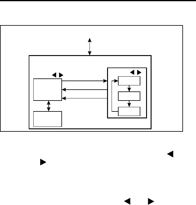
Menu Mode Flowchart
2. To scroll through the available menu parameters, press the (scroll
down) and (scroll up) keys. Then to display and change the selected
option for an parameter, proceed as follows:
•To display the selected option for a parameter, press the STR key.
•To change the selected option, press the and keys.
•To exit back to the parameter and save the selected option, press FCN
STR.
•To exit back to the parameter without changing the selected option,
press STR.
3. When the desired condition of each menu parameter is selected, exit the
menu mode by pressing FCN MENU again. The menu mode is also
automatically exited 2 seconds after a change is made or 8 seconds after
no changes are made.
Enter/Exit
Menu Mode
Press FCN MENU
BANK
SEL
Other Menu
Parameters
MENU
PARAMETERS
PARAMETER
OPTIONS
STR
FCN STR (Chg)
Bank 1
Bank 2
Bank x
Select by Press
STR (No Chg)
pressing

DIAL MODE
38
DIAL MODE
Introduction
When placing calls that require a number be dialed (telephone and
auxiliary), using the dial mode allows the number to be dialed at any
convenient rate, dialing errors to be corrected, and then the radio system
to be automatically accessed and number transmitted when desired. The
dial mode also allows up to ten 16-digit numbers to be stored in memory
and later recalled.
When in the dial mode, the SYS and GRP keys become RCL
(Recall) and CLR (Clear) keys. Therefore, the selected system and group
cannot be changed when the dial mode is selected. The information
which follows describes how the dial mode is used.
Selecting Dial Mode
Selecting Dial Mode and Telephone Group - To select the dial mode and a
telephone group in the current system, press FCN PHONE. If there is more
than one group programmed for telephone calls in the current system, the
first high numbered telephone group is selected. If there is no telephone
group or a conventional system is selected, “NO PHONE” is displayed and
an error tone sounds.
Selecting Dial Mode Without Changing Selected Group - To select the dial
mode without changing the currently selected group, press FCN DIAL.
This method should be used when placing auxiliary calls because the
auxiliary call group and not the telephone group must be selected.
The dial mode is indicated when the handset portion of the tele-
phone icon is displayed. The base portion is displayed when a tele-
phone group is selected, and “UID” is displayed when an auxiliary call
group is selected.

DIAL MODE
39
Dialing a Number
Enter the desired number by pressing the 0-9, , and keys. Other
dialing functions are as follows:
•Only the last 8 digits dialed are displayed. To momentarily display
the upper 8 digits, press FCN .
•To erase the last digit, press the CLR key (hold it down to repeat). To
erase the entire number, press FCN CLR.
•To enter a pause, press FCN (each pause equals one character).
Sending the Number
To automatically access the radio system and send the number in the
display, press FCN SND. The keypad remains active while in a conversa-
tion to allow additional numbers to be dialed. Simply press the PTT
switch and dial the number. The number in the display does not change
when a number is dialed in this manner. If you want to save the number in
the display (see following information), make sure you do so before the
dial mode is exited.
Storing Numbers in Memory
Up to ten 16-digit numbers can be stored in memory and later
recalled. Proceed as follows to store a number:
1. Enter the number as described in the preceding “Dialing a Number”
section.
2. To store the number, press FCN RCL and the memory location from
0-9.
3. If there is already a number in the selected location, it is replaced by the
new number. To clear a memory location, simply store a blank display.
#
DIAL MODE
40
NOTE: The character is stored and sent normally (no pause occurs),
and the character should not be stored because it may terminate the
call when it is sent.
Recalling Numbers From Memory
From Specific Location - FCN RCL 0-9 (location number)
Stored in Next Location - RCL (hold down to repeat). If a number is
already displayed, the number in the next higher location is indicated; if
display is blank, the number in location 1 is indicated first.
Last Number Dialed by Recalling from Memory - FCN RCL
Last Number Dialed - FCN RCL
Exiting Dial Mode
Without Sending Call Termination Characters - To exit the dial mode
without sending the call termination characters, press FCN DIAL.
Sending Call Termination Characters - To exit the dial mode and send the
characters which automatically terminate the call, press FCN PHONE.
Terminating a call in this manner prevents any additional billing for the
time required to automatically detect the end of a call.
Placing Calls Without Selecting Dial Mode
Telephone and Auxiliary calls can also be placed without selecting
the dial mode by using the procedure which follows:
1. Access the radio system by briefly pressing the PTT switch.
2. When a dial tone is heard, dial the desired number while pressing the
PTT switch. If too much time elapses between digits, the call is auto-
matically terminated.
NOTE: When receiving telephone or auxiliary calls, the selection of the
dial mode is optional because it does not enhance operation.
#

SYSTEM AND GROUP SCANNING
41
SYSTEM AND GROUP SCANNING
General
Introduction
The scan feature monitors, in sequence, the systems and/or groups in
the scan list. When a message is detected that the transceiver is
programmed to receive, scanning stops and the message is received.
Shortly after the message is complete, scanning resumes (unless it has
been disabled). System and group scanning or group scanning only may
be used (see next page), and the operation of each type is as follows.
Refer to page 23 for more information on systems and groups.
System Scanning - Detects calls on all systems in the system scan list.
If system scanning is not used, calls are detected on only the currently
selected system.
Group Scanning - Detects calls on all groups in the group scan list.
These groups are from the selected system and also from scanned
systems if system scanning. If group scanning is not used, calls are
detected on only the selected group. In addition, calls may be detected
on higher priority LTR-Net and LTR groups (see “Priority Calls” on
page 46).
Scan On-Off
System and/or group scanning are turned on and off by pressing
FCN SCAN. When either type of scanning is enabled, is indicated in
the display (see following illustration). Then when group scanning is
actually occurring, dashes are displayed instead of a group number (if the
numeric display mode described on page 20 is selected). Group scanning
is not indicated if the alpha display mode is selected, and system scanning
is never indicated. The monitor mode must be disabled for scanning to
occur (see page 50).
SYSTEM AND GROUP SCANNING
42
Scan Types
The type of scanning selected is determined by the menu mode SCN
TYPE parameter (see page 36). If it is not selectable, the scan type is
fixed by system operator programming. The available scan types are as
follows.
SYSTEMS - Both system and group
GROUPS - Group scanning only
OFF - Both types disabled (scanning not selectable)
If the scan on-off key (FCN SCAN) is disabled, the selected mode is
always enabled. If both this key and the SCN TYPE menu parameter are
disabled, the scan mode and type are fixed by programming. The selected
system and group can be changed while scanning using the SYS and GRP
keys in the normal manner. Scanning resumes shortly after the change is
made.
When a call is received in the scan mode, the display changes to the
system and group of the call. Programming determines if this change is
temporary or permanent, and if a response occurs on the system/group of
the call or the selected system/group. Refer to “Transmitting In The Scan
Mode” on page 45 for more information.
G
S
System Scan List Group Scan List
System or Group
Scanning Selected
Group
Scanning Occurring

SYSTEM AND GROUP SCANNING
43
LTR-Net Mode Scanning
When system scanning with an LTR-Net system selected and
roaming disabled, only the LTR-Net systems in the scan list that access the
site of the selected system are scanned (any LTR and conventional
systems are not scanned). If roaming is enabled, registration on other sites
occurs normally and scanning of LTR-Net systems occurs as just
described.
However, if the current LTR-Net site is lost and no other LTR-Net
site can be located, the LTR and conventional systems in the scan list are
also scanned. Searching for an LTR-Net site continues and if one is again
detected, registration on that site occurs and the LTR and conventional
systems are no longer scanned. This operation can provide uninterrupted
operation in areas which have not been converted to LTR-Net operation.
LTR and Conventional Mode Scanning
When an LTR or conventional system is selected with system scan-
ning enabled and roaming disabled, scanning is sequential through only
the LTR and conventional systems in the scan list (LTR-Net systems are
not scanned). If roaming is enabled, all three system types or only LTR-
Net systems may be scanned as described in the preceding LTR-Net
description.
Scan List Programming
General
NOTE: The selected (displayed) system and group are always scanned
even if they have been deleted from the scan list.
The scan list status of the displayed system is changed by pressing
FCN S.A/D, and the status of the displayed group is changed by pressing
FCN G.A/D. The displayed system is in the scan list and scanned
normally when is displayed, and the displayed group is scanned when
is displayed (see preceding illustration). Deleting a system only
temporarily deletes the groups associated with that system because when

SYSTEM AND GROUP SCANNING
44
a system is added back into the scan list, the original group scan list is
again active.
Systems and groups can be deleted from the scan list in the normal
manner while listening to a message on the system or group by simply
pressing the S.A/D or G.A/D key. Scanning resumes shortly after the
system or group is deleted. The S.A/D and/or G.A/D functions can also be
disabled by programming. The scan list programming function performed
by that switch is then not available.
Saving Scan List
If the menu mode SCN SAVE parameter is available (see page 36),
you can select if scan list changes are saved. If “On” is selected, changes
are saved as they are made and the scan list does not change when power is
turned off. Conversely, if “Off” is selected, they are not saved and the
default status of all systems and groups is reselected when power is turned
on. If the menu SCN SAVE parameter is not selectable, the scan list save
mode is fixed in one of these states.
Scan Delay and Continue Timers
When a message is received or transmitted while scanning, there is a
short delay before scanning resumes. The delay after receiving a call
prevents another message from being received before a response can be
made. Likewise, the delay after transmitting a call ensures that you hear a
response to your call instead of another message occurring on some other
system or group. Note that scanning does not resume if it has been
disabled, such as by selecting the monitor mode.
There is also a scan continue timer that may be programmed. This
timer controls the maximum time that a call is received before scanning
resumes. Times up to 60 seconds can be programmed. This prevents scan-
ning from being delayed for long periods by lengthy calls. If the menu
SCN CONT parameter is selectable (see page 36), this feature can be
turned on and off.

SYSTEM AND GROUP SCANNING
45
Transmitting In The Scan Mode
General
When messages are received while scanning, programming deter-
mines if the selected system/group does not change, changes permanently
to the new system/group, or changes temporarily. This in turn affects the
system/group on which responses occur. The display always indicates the
system/group on which a call is received, but this may not be the system/
group on which a response occurs. The three programmable configura-
tions operate as follows:
Last Selected - Transmissions always occur on the system/group that
was selected manually by the SYS and GRP keys or automatically by
roaming. Therefore, to respond to a message that is not on the selected
system/group, the selected system/group must be changed using one of
these methods:
•Select the system/group of the call manually using the SYS and GRP
keys.
•Before scanning resumes, exit the scan mode by pressing FCN SCAN.
The system/group of the call then becomes the selected system/group
and it is not necessary to change it manually.
Last Received - The selected system/group changes to the system/group
of a call. Therefore, you can always respond to a call without having to
manually change the system/group. To return to the previously selected
system/group, it must be manually selected using the SYS and GRP keys.
Temporary Last Received - The system/group changes to the system/
group of a call for only the duration of the scan delay period (see
page 44.) Then when the delay expires and scanning resumes (if it is not
disabled), the selected system/group is again displayed. Therefore, you
can respond to a call without changing the selected system/group as long
as you do so before scanning resumes.

LTR-NET AND LTR FEATURES
46
LTR-NET AND LTR FEATURES
Transmit Inhibit
The Transmit Inhibit feature prevents the transmitter from keying if
the mobile you are calling is busy with another call. When the transmitter
is disabled by this feature, the intercept tone sounds and “TX INHIB” is
displayed (see following illustration). To make another call attempt, the
PTT switch must be released and pressed again. However, you may want
to wait a few seconds before making another attempt because a timer
must time out before another attempt will be successful. A similar
Transmit Disable On Busy feature is available on conventional systems
(see page 51).
Priority Calls
Each LTR-Net and LTR group is programmed with a receive priority
number. If a call is detected on a group in the group scan list that has a
higher priority than the selected group, it is received (even if scanning is
not enabled). If another call is in progress when the higher priority call is
detected, the current call is immediately dropped. Some groups, such as
those used to make telephone calls, may be programmed as not interrupt-
ible to prevent other calls from interrupting a call in progress.
The system/group of the priority call is displayed while it is
received. The programming described on page 45 determines if the
change is temporary or permanent and if a response occurs on the last
selected or received system/group.

LTR-NET FEATURES
47
LTR-NET FEATURES
NOTE: Other LTR-Net features are described starting on page 46.
LTR-Net Standard Calls
Standard group calls are between two mobiles or between a mobile
and a control station. To place these calls in the LTR-Net or LTR mode,
simply select the desired group and press the PTT switch (no number is
dialed) as described starting on page 29.
LTR-Net Special Calls
The LTR-Net Special calls are as follows:
Telephone Calls - These calls allow you to place and receive telephone
calls using your transceiver. They are described starting on page 31.
Auxiliary Calls - As shown in the preceding illustration, these calls include
Unique ID and Directed Group calls. Unique ID calls are to specific
mobiles, and Directed Group calls are to specific talk groups. Refer to
page 33 for information on placing and receiving Auxiliary calls.
Busy Queuing
If system resources are not available when placing special calls,
queuing may be provided by the radio system. Standard group calls are
not queued. When a call is placed in a queue, a voice message informs
you that this has occurred. Then when resources become available, the
call is automatically placed and the normal ringing or other tones are
heard if applicable. If the call cannot be placed in the allotted time, it is
terminated and another message informs you that this has occurred.
Special
Telephone
Auxiliary
Directed Group
Unique ID

LTR-NET FEATURES
48
Roaming
LTR-Net radio localities (sites) can be linked together to provide
wide area coverage. Calls can then be automatically routed to your
current location as you travel from locality to locality. Both standard
group and special calls may be routed in this manner. If your transceiver
is programmed for roaming, this feature is utilized as follows:
1. Enable roaming using the Roam option switch or ROAMING menu
parameter (see page 35) if available. When roaming is enabled and
disabled by the option switch, “ROAM ON” and “ROAM OFF” are
momentarily displayed. If neither the menu parameter nor option
switch is available, roaming is fixed in the on or off mode by program-
ming.
2. If scanning is disabled, an LTR-Net system must be selected. If system
scanning is enabled, any system can be selected if the LTR-Net systems
are in the system scan list (see page 43).
When roaming is enabled as just described and the signal from the
current locality becomes weak, the transceiver automatically begins
searching for another locality. While searching is occurring, “LCL
SRCH” is displayed as shown below. Then when a new locality is
located, registration occurs and “LCL SRCH” is no longer displayed. The
displayed system is then the next LTR-Net system programmed with a
different locality that could be accessed, and the displayed group is
usually the group that was displayed before roaming occurred.

LTR FEATURES
49
LTR FEATURES
NOTE: Other LTR features are described starting on page 46.
Standard Group Calls
Standard group calls are between two mobiles or between a mobile
and a control station. To place these calls in the LTR or LTR-Net mode,
simply select the desired group and press the PTT switch (no number is
dialed). The procedure for placing and receiving these calls is described
starting on page 29.
Telephone Calls
Telephone calls allow you to place and receive calls over the public
telephone system using your transceiver. LTR and LTR-Net telephone
calls are described starting on page 31.
CONVENTIONAL FEATURES
Squelch Adjust
This function sets the squelch level used for conventional calls.
Since the squelch level for LTR-Net and LTR calls is preset and cannot be
changed, this adjustment needs to be made only if you make conventional
calls (refer to page 23 for more information on operating modes). Proceed
as follows:
1. Select a conventional system and a group that is not busy. If the selected
channel is programmed for Call Guard squelch, press the Monitor
option switch to enable monitoring (see page 50).
2. Press FCN SQL to select the squelch adjust mode. The currently
selected squelch level is then indicated by “SQ xxx” in the display.

CONVENTIONAL FEATURES
50
3. Press the key until receiver noise is heard and then press until
the noise just mutes. To decrease or increase the selected level in steps
of 10 (or select the minimum or maximum level if this is not posssible),
press FCN or FCN , respectively.
NOTE: Slight readjustment may be required if weak messages are not
heard or unsquelching occurs when no messages are present.
4. To exit this mode, press the FCN SQL again. Exiting also occurs auto-
matically after 2 seconds of no activity.
5. If both narrow and wide band channels are used, perform this adjust-
ment for each type because separate settings are maintained.
Monitoring Before Transmitting
General
Regulations require that conventional channels (groups) be moni-
tored before transmitting to make sure that they are not being used by
someone else. If you were to transmit when someone else is talking, you
would probably disrupt their conversation. Proceed as follows to auto-
matically or manually monitor conventional channels. In the LTR-Net
and LTR modes, monitoring is always performed automatically.
Automatic Channel Monitoring
If the selected group is programmed with the Transmit Disable On
Busy feature (see page 51), monitoring is performed automatically. If not,
it must be monitored manually using one of the methods which follow.
Busy Indicator
With scanning disabled and the squelch properly adjusted (see
page 49), note if “BUSY” is indicated in the display (see following illus-
tration). If it is, a signal is being detected on the selected group (channel)
and you should not transmit a message until it turns off.
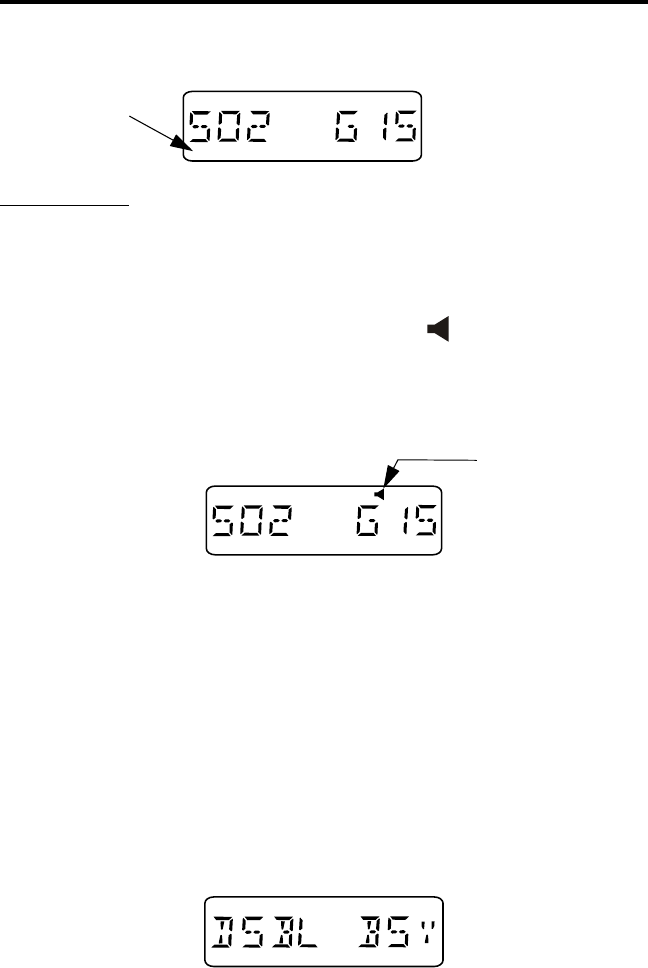
CONVENTIONAL FEATURES
51
Monitor Mode
There may be times when the Busy indication is displayed even
though no one is using the channel. Monitoring should then be performed
using the monitor mode. This mode is enabled by pressing the Monitor
option switch (see page 35), and is indicated by in the display as
shown in the following illustration. While this switch is pressed, both
Call Guard squelch (see page 52) and scanning are disabled so that any
activity on the group is heard.
A conventional system must be selected to enable monitoring. If the
Monitor option switch is pressed with an LTR-Net or LTR system
selected, scanning halts but monitoring is not enabled.
Transmit Disable On Busy
The Transmit Disable On Busy feature automatically disables the
transmitter if the selected group (channel) is busy and it has not been
monitored when the PTT switch is pressed. When the transmitter is
disabled by this feature, the busy tone sounds briefly and “DSBL BSY” is
indicated in the display as follows:
While the PTT switch is pressed, the receiver is enabled so that
activity on the channel can be monitored. The PTT switch must be
BUSY
Busy
Indicator
Monitor Mode
Selected

CONVENTIONAL FEATURES
52
released and then pressed again to make another call attempt. Occasion-
ally, a busy condition may be detected even though no one is talking. To
key the transmitter in this case, release the PTT switch and then immedi-
ately press it again.
There is also a programmable option with this feature to allow trans-
mitting with a busy channel if the correct Call Guard signal is detected.
The Transmit Disable On Busy feature is enabled or disabled on each
conventional group by system operator programming. If this feature is
disabled or if monitoring has been performed by taking the microphone
off-hook, the transmitter keys even if the group is busy.
Talk-Around
Normally, all transmissions go through a repeater which usually
increases range because the repeater transmits at a higher power level and
has a higher antenna. However, this means that if you are out of radio
range of the repeater, you cannot talk to anyone even if the mobile you
are calling is only a short distance away. To allow communication if this
occurs, talk-around groups can be programmed which enable direct
mobile-to-mobile communication without going through a repeater.
Talk-around is then automatically enabled by selecting one of these
groups. There is no special talk-around option switch or indicator.
However, the group alpha tag on the lower line of the display may be
used to indicate groups programmed for this feature. Talk-around is not
available on LTR-Net and LTR systems.
Call Guard Squelch
The Call Guard squelch feature eliminates distracting messages
intended for others using the channel. This is done by using a subaudible
tone or digital code to control the squelch. This tone or code is unique to
a user or a group on that channel. It is transmitted with the voice signal
but is not heard because it is in the subaudible range and attenuated by a
filter. Call Guard squelch can be programmed on each conventional
group. LTR-Net and LTR operation uses ID codes to perform a similar
function.

MISCELLANEOUS
53
MISCELLANEOUS
Supervisory Tones
The following tones are heard at various times when operating this
transceiver. Some or all of these tones can be disabled by the TONES
menu parameter or programming (see “Tone Select” on page 29).
Busy Tone
This tone is similar to the standard telephone busy tone, and it indi-
cates that the radio system is currently busy. The display also indicates
“BUSY” while this tone is sounding. Repeated access attempts are made
while the PTT switch pressed with this tone sounding. Therefore, it is not
necessary to release the PTT switch to access the system. This tone
sounds only with LTR-Net and LTR calls.
Intercept Tone
This is a siren-like tone (alternating high and low tones) which indi-
cates the following no access and error conditions:
•No Access - If this tone sounds shortly after pressing the PTT switch
and “NO ACCES” is displayed, the radio system could not be
accessed, perhaps because of an out-of-range condition (see “Opera-
tion At Extended Range” on page 60). Once this tone sounds, no
more access attempts are made until the PTT switch is released and
then pressed again. This condition is indicated only with LTR-Net
and LTR calls.
•Time-Out Timer - If this tone sounds after the transmitter has been
keyed for an extended period and “TIMEOUT” is displayed, the
transmitter has been disabled by the Time-Out Timer feature (see
page 28).
•Transmit Inhibit - If this tone sounds as soon as the PTT switch is
pressed with an LTR-Net or LTR system selected and “TX INHIB”

MISCELLANEOUS
54
is displayed, the transmitter has been disabled by the Transmit
Inhibit feature (see page 46).
•Receive-Only Group - If this tone sounds as soon as the push-to-talk
switch is pressed and “TX DISBL” is displayed, the group is receive-
only (see page 28).
Proceed (Clear-To-Talk) Tone - This is a short single or double tone
which sounds after the push-to-talk switch is pressed to indicate when
talking can begin (see page 27).
Key Press Tone - This is a short tone that indicates when an option switch
is pressed.
Wrap-Around Tone - This is a two-pitch tone that indicates that the highest
or lowest channel was displayed and that wrap-around has occurred.
Error Tone - This is a two-pitch tone that indicates that an error condition
has occurred.
LTR-Net Special Call Tones
The following tones are generated by the LTR-Net equipment and
are heard when making a telephone, unique ID, or directed group special
call on an LTR-Net system.
Confirmation Tone - This is a short tone that sounds when the number
just dialed has been accepted by the system.
Call Proceed Tone - With LTR-Net directed group calls (see page 34),
ringing does not occur after the number is dialed. Instead, another short
tone sounds after the confirmation tone to indicate that the audio path is
complete and speaking can begin.
End Call Tone - Three beeps which indicate that the end of the call has
been detected by the system.

MISCELLANEOUS
55
Proceed Dialing Tone - When placing a landside-to-mobile telephone
call (see page 33), the landside caller may enter a special number which
specifies the mobile being called. This tone indicates when that number
should be dialed.
LTR Telephone Call Tones
The following tones are generated by LTR interconnect equipment
and are heard when making LTR telephone calls.
Reorder Tone - Three beeps which indicate that the call has been termi-
nated by the system.
Return Time Warning Tone - Two beeps which warn that you have not
transmitted for an extended period. If you do not transmit within 5
seconds, the call is automatically terminated by the system. The time
between transmissions is one of the parameters used by the system to
detect the end of a call when the # character is not sent.
Conversation Time-Out Tone - Calls are limited to a certain length by
the system. Thirty seconds before this time is reached, a “tick” begins
sounding each second. When the 30-second time expires, the call is auto-
matically terminated by the system.
Turn-Around Tone - This is a single beep which may be used to indicate
to the landside party when to respond to your transmission. It sounds
when you release the PTT switch, and you may partially hear this tone.
Proceed Tone - This tone consists of two beeps and it tells the landside
caller when to enter the five-digit number specifying the mobile being
called. Dialing of this number must be started within 5 sec. of hearing this
tone, and a tone-type telephone must be used.
Display Messages
The following messages appear in the display to indicate various
operating modes and error conditions.

MISCELLANEOUS
56
BUSY - Indicates that the LTR-Net or LTR radio system is currently busy
(see “Busy Tone” on page 53).
CALL SVC - Indicates that the transceiver is inoperative. Contact your
system operator for service.
DSBL BSY - Indicates that the transmitter is disabled by the conven-
tional Transmit Disable On Busy feature (see page 51). It also indicates
that the transmitter was keyed while receiving an LTR-Net or LTR call.
FCN - Indicates that the function select mode is selected by the FCN
option switch (see page 15).
LCL SRCH - Indicates that the transceiver is currently searching for a
new locality (site) on which to register (see page 48).
Model - The last seven digits of the transceiver part number are indicated
very briefly in the display when transceiver power is turned on. This
number indicates such things as frequency band, power output, and tier of
the transceiver. The eighth digit is reserved and always “0”.
NO ACCES - Indicates that the radio system could not be accessed,
perhaps because of an out-of-range condition. Refer to “Operation At
Extended Range” on page 60 for more information.
NO PHONE - Indicates that there is no telephone group programmed in
the current system when the dial mode is selected by pressing FCN
PHONE (see page 38).
NOT AUTH - Indicates that an attempt was made to register on a site
where service was not authorized (see page 48).
NOT CONV - Indicates that an attempt was made to enable a conven-
tional mode feature on an LTR-Net or LTR system.
NOT LNET - Indicates that an attempt was made to enable an LTR-Net
mode feature on an LTR or conventional system.

MISCELLANEOUS
57
OUT-LOCK - Indicates that the synthesizer is unlocked. Refer to
“Transceiver Service” on page 60 for more information.
PROG ERR - Indicates an EEPROM read error. Refer to “Transceiver
Service” on page 60 for more information.
SLEEPING - Indicates that the transceiver has been temporarily disabled
by the system operator. It will be automatically enabled again when oper-
ation can be resumed.
SQUELCH - Indicates that the conventional squelch adjust mode is
selected (see page 49).
TIMEOUT - Indicates that the transmitter has been disabled by the
Time-Out Timer (see page 28).
TX DISBL - Indicates that the transmitter has been disabled because the
selected group is receive-only (see page 28).
TX INHIB - Indicates that the transmitter has been disabled by the
Transmit Inhibit feature (see page 46).
Menu Mode Messages
The following messages are displayed in the menu mode that is
described starting on page 35. The enabled or “yes” condition is indicated
by “ON”, and the disabled or “no” condition by “OFF”.
BANK SEL - Bank select
•Bank alpha tag
ENCRYPT - Encryption select
•ON or OFF
OPTION - Option on-off
•ON or OFF

MISCELLANEOUS
58
ROAMING - LTR-Net roaming on-off
•ON or OFF
SCN CONT - Scan continue on-off
•ON or OFF
SCN SAVE - Scan list save
•ON = save, OFF = not saved
SCN TYPE - Selects type of scanning
•SYSTEM - Both system and group
•GROUPS - Group scanning only
•OFF - All scanning disabled
STEALTH - Stealth mode select
•ON or OFF
TONES - Beep tones select
•SILENT - All tones disabled
•KEYS - Only Select switch and key press tones sound
•ALERTS - All tones sound except preceding Key Beeps sound
•ALL - All the preceding tones sound
Rechargeable Battery Pack
WARNING
Do not dispose of the battery pack in fire because it may explode. The
battery pack contains nickel metal-hydride (NiMH) cells which must be
disposed of in accordance with local regulations. Do not short the termi-
nals because the battery may become very hot.
Battery Life
With proper care, the nickel metal-hydride (NiMH) battery pack
used by this transceiver should provide excellent service. When the pack
no longer holds a charge or provides only a very short operating time, it
must be replaced with a new unit.

MISCELLANEOUS
59
Typical operating time before recharging is required is 8 hours. This
assumes that the transceiver is transmitting at high power 5% of the time,
receiving and producing audio 5% of the time, and in the standby mode
(receive with audio muted) 90% of the time. If the low-power mode is
selected or different times are spent in these modes, operating time varies
accordingly. The charge of the battery and ambient temperature also
affect operating time.
NOTE: Be sure to turn transceiver power off before removing the battery
pack. Failure to do so may result in current settings not being saved in
memory.
Recharging
Recharging is required when the icon is displayed as
described on page 23. The pack can be recharged while still on the trans-
ceiver or it can be charged separately. To remove the battery pack from
the transceiver, press the spring-loaded release button on the bottom and
slide the battery off. A new battery pack must be charged before use.
Battery Care
One cause of shortened battery life is repeated deep discharge.
Therefore, it is recommended that the battery be recharged as soon as
practical after the low-battery indication appears (see preceding informa-
tion). Do not continue using the transceiver until the battery is completely
discharged. Another cause of reduced battery life is operation at tempera-
ture extremes. It is also good practice not to regularly leave a pack in the
charger for extended periods after it is completely charged.
It is possible that the pack could develop a characteristic called
“memory” although these packs are designed to minimize that problem.
When a pack has this problem, it acts as if it is totally discharged even
though it has greater capacity. This can be caused by discharging a pack
only slightly before recharging, charging at too high a temperature, or
extended storage. If a pack develops this problem, it can usually be
corrected by performing three discharge/charge cycles.

MISCELLANEOUS
60
Speaking Into Microphone
For best results, hold the speaker grille about 1-2 inches from you
mouth and speak at a normal conversational level. Do not shout since it
distorts you voice and does not increase range. Make sure that the PTT
(push-to-talk) switch is pressed before you begin to speak and released as
soon as the message is complete.
Operation At Extended Range
When approaching the limits of radio range, the other party may not
be able to hear your transmissions and there may be an increase in back-
ground noise when messages are received.
Even though you can hear messages, you may still be out of radio
range. The reason for this is that the signal being received is normally
transmitted by a repeater which usually has a much higher power level
than is produced by your transmitter. Communication may be improved
by moving to higher ground or away from shielding objects such as tall
buildings or hills.
Licensing
A government license is usually required to operate this transceiver
on the air. Your system operator will normally handle the licensing
requirements.
Transceiver Service
If your transceiver is not operating properly, “OUT-LOCK”, “PROG
ERR”, “SLEEPING”, or “CALL SVC” may be displayed. It may be
possible to clear the first two conditions by turning power off and then on
again to reset the control logic. Also make sure that the controls are prop-
erly set and that the battery is fully charged. If the transceiver still does
not operate properly, return it to your system operator for service.

INDEX
61
The “SLEEPING” message indicates the transceiver is temporarily
disabled as described on page 57. If the CALL SVC message is
displayed, the transceiver must always be returned to your system oper-
ator for service.
NOTE: There are no user-serviceable components in the transceiver.
Altering internal adjustments can cause illegal emissions, void the
warranty, and result in improper operation that can seriously damage the
transceiver.
INDEX
A
Accessory Connector 12
Alpha Tag Display Mode 21
Alphanumeric Display 13
Antenna Care 4
Antenna Jack 12
Auxiliary Call 47
Placing 33
Receiving 35
B
Backlight 20
Battery Pack 58
Battery Release Button 12
Busy Queuing 47
Busy Tone 53
C
Call Guard Squelch 52
Call Indicator 14, 25
Clear-to-Talk Tone 27
CLR Key 16
Controls
On-Off/Volume 11
Option Switch 12
PTT Switch 12
Top Panel 11
Conventional Mode 24
Conventional Mode Scanning 43
D
DIAL Key 17
Dial Mode 38
Exiting 40
Selecting 38
Dialing a Number 39
Directed Group Call 33
Directed Group Calls 47
Disabling Keypad 22
Display 13
Display Messages 55
Display Mode
Alpha Tag 21
Numeric 21
Display Modes 20
E
Emergency Switch 26
F
FCC Rules 2
FCN Key 15
Features
Conventional 10
General 10
LTR 10
LTR- N et 10
Front Panel Keys 15

INDEX
62
G
G.A/D Key 18
Group Call 29, 47
Group Scanning 41
GRP Key 16
H
HOME Key 16
Home System/Group Select 27
I
Important Operating Information 4
Indicator
Auxiliary Call Group 14
Busy 14, 50
Call 14, 25
Directed Group Call 14
Encryption 13, 26
Group Scan List 14
Keypad Lock 14
Low Battery 14
Low Power 13
Monitor Mode 14
Priority 14
Scan 13
Stealth Mode 14
System Scan List 13
Telephone Group 13
Transmit 14
Unique ID Call Group 14
Intercept Tone 53
Interference 4
K
Keypad Disable 22
L
Landside-Originate Telephone
Call 33
Licensing 60
Low Battery 23, 27
LTR Mode 23
LTR Mode Scanning 43
LTR-Net Mode 24
LTR-Net Mode Scanning 43
M
MENU Key 17
Menu Mode 36
Bank Select 25
Encryption 26
Messages 57
Option Select 27
Power Select 27
Roam 48
Stealth 28
Tone 27, 29
Messages 55
Mobile-to-Mobile Call 29
Monitor Mode 51
Monitoring Before Transmitting 50
N
Numeric Display Mode 21
O
On-Off/Volume Control 11
Operating Modes 23
Operation at Extended Range 60
Option Select 27
Option Switch 12, 23, 35
Auxiliary 27
Emergency 26
Encryption 26
Roam 48
P
PAGE K e y 17
PHONE Key 16
Power Select 27
Power-Up Sequence 20
Priority Calls 46
Proceed Tone 27
Push-to-Talk Switch 12

INDEX
63
Q
Quick Reference Guide 9
R
RCL Key 16
Recalling a Number 40
Receive-Only Groups 28
Rechargeable Battery Pack 58
Roaming 48
S
S.A/D Key 18
Safety Information 2
Scan Delay and Continue Timers 44
SCAN key 15
Scan List
Programming 43
Saving 44
Scan Mode 41
Transmitting 45
Scan Types 42
Selecting System/Group 21
SEND Key 18
Sending a Number 39
Service 60
Speaking Into Microphone 60
Special Calls 47
SQL Key 17
Squelch Adjust 49
Standard Group Call 47, 49
Placing 29
Receiving 31
Stealth Mode 28
Storing a Number 39
STR Key 18
Supervisory Tones 53
SYS Key 16
System and Group Select 21
System Scanning 41
T
Talk-Around 52
Telephone Call 49
Landside Originate 33
Placing 31
Receiving 33
Telephone Calls 47
Time-Out Timer 28
Tone Select 29
Tones
LTR Telephone Call 55
LTR-Net Special Call 54
Supervisory 53
Transmit Disable On Busy 51
Transmit Inhibit 46
U
Unique ID Call 33, 47
Usage
Blasting Areas 4
Children 4
Explosive Atmospheres 5
Flammable Atmospheres 5
V
Volume Level Adjust 20
W
Warranty 3

Part No. 002-7200-600
9-00hph Printed in U.S.A.