E F Johnson 2427240 UHF FM Handheld Transceiver Held-to-face User Manual W Omarks for FCC
E. F. Johnson Company UHF FM Handheld Transceiver Held-to-face W Omarks for FCC
UserManual.wiki
>
E F Johnson
>
2427240 User Manual
>
User Manual
Contents
1.
User Manual
2.
Revised Manual
3.
Revised User Manual
4.
Revised Page of Manual
5.
users manual
User Manual
Navigation menu
Upload a User Manual
Namespaces
Wiki Guide
HTML
PDF
Info
Views
User Manual
Discussion / Help
Navigation
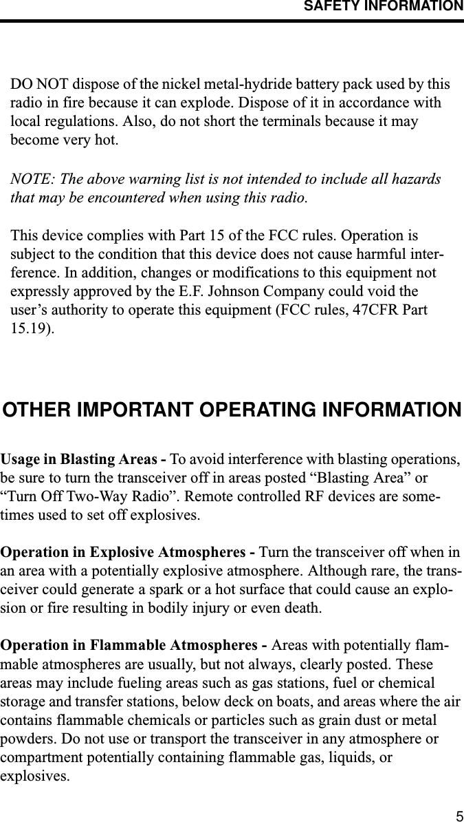
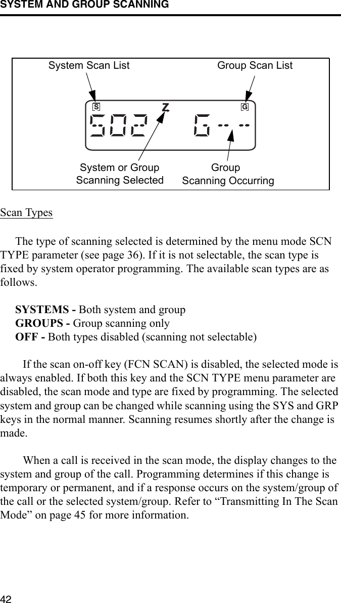
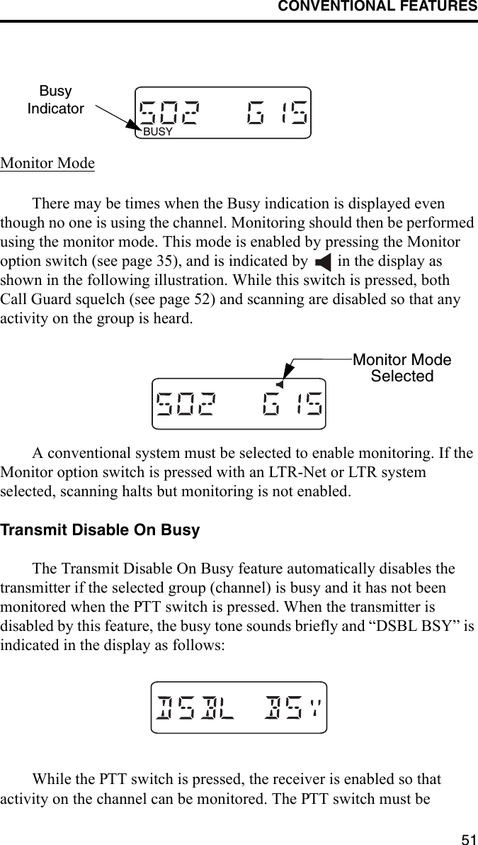
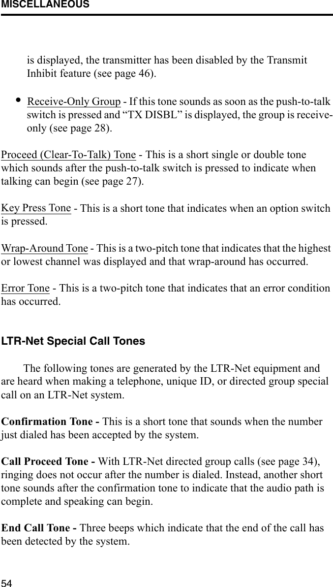
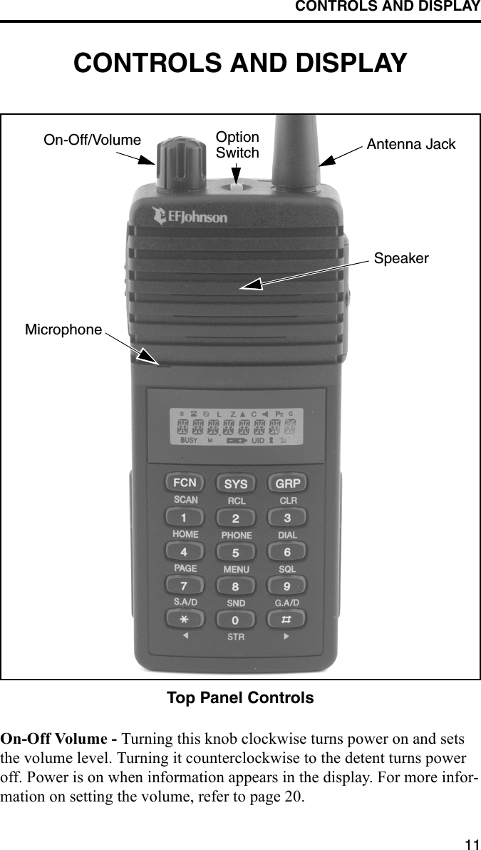
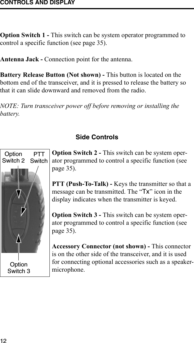
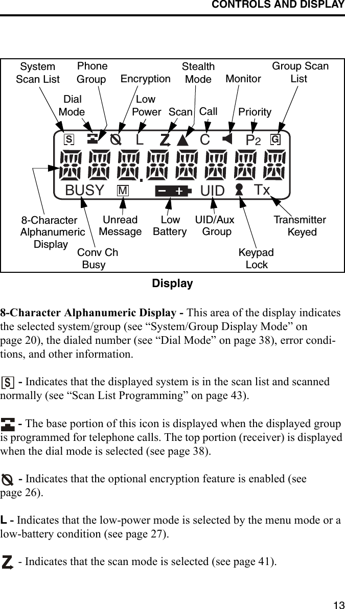
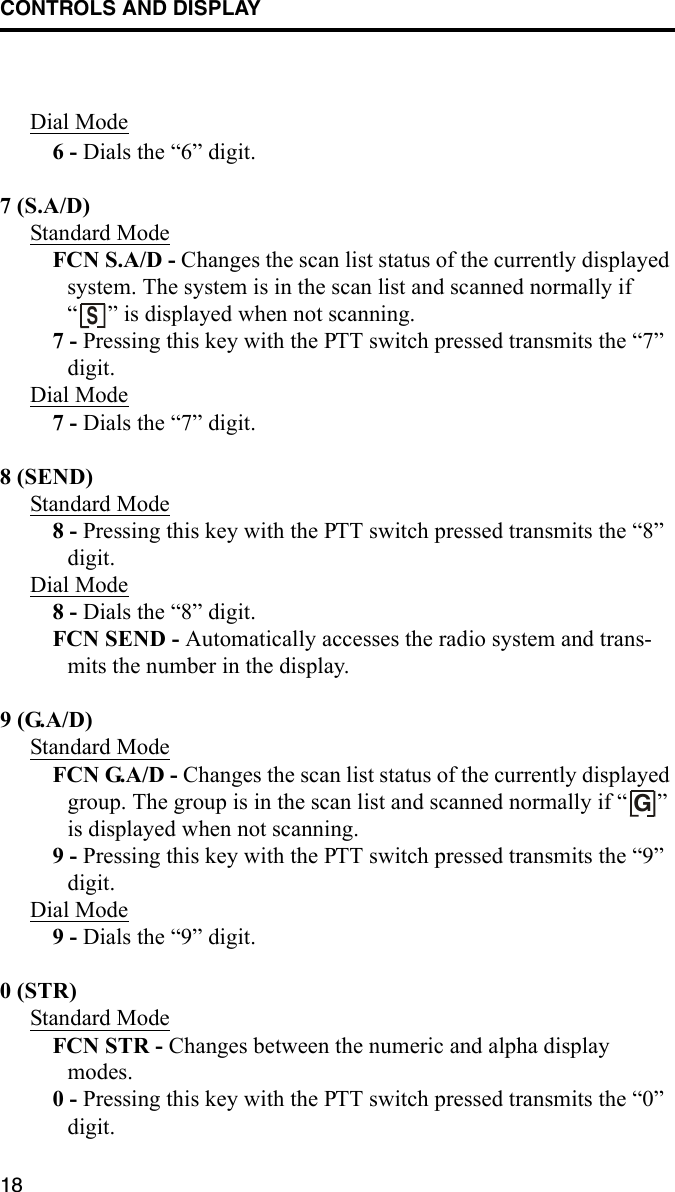
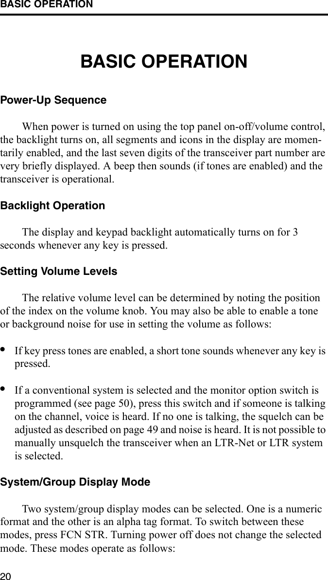
![QUICK REFERENCE GUIDE9QUICK REFERENCE GUIDEChange system number - Press SYS or or SYS (1-99) [pg 21]Change group number - Press GRP or or GRP (1-99) [pg 21]System scan on/off - FCN SCAN ( indicates scanning is enabled) [pg 41]Change scan list status of displayed system - FCN S.A/D ( indicates that the system is in the scan list and scanned normally) [pg 43]Change scan list status of displayed group - FCN G.A/D ( indicates that the group is in the scan list and scanned normally) [pg 43]Change between alpha and numeric display modes - FCN STR [pg 20]Display home or last active system/group - FCN HOME [pg 27]Select/Exit Menu Mode - FCN MENU [pg 36]Lock/Unlock Keypad - FCN ( indicates locked keypad) [pg 22]Adjust Squelch (conventional only) - FCN SQL then and [pg 49]NUMBER DIALINGSelect dial mode without changing system/group - FCN DIAL [pg 38]Select dial mode and telephone system/group) - FCN PHONE [pg 38]Transmit number in display - FCN SND [pg 39]Erase last number in display - CLR [pg 39]Erase entire number in display - RCL CLR [pg 39]Display overflow digits - FCN [pg 39]Enter a pause - FCN [pg 39]Store a number in memory - Enter no., then FCN STR (0-9) [pg 39]Display numbers in memory - RCL (hold down to repeat) [pg 40]Recall number from a memory location - FCN RCL (0-9) [pg 40]Recall last number dialed - FCN RCL [pg 40]Recall last number dialed from memory - FCN RCL [pg 40]Exit dial mode and terminate call - FCN PHON [pg 40]Exit dial mode without terminating call - FCN DIAL [pg 40]BUSYMGSUID TxP2CLOSystemScan ListPhoneGroupGroup ScanListScan Call8-CharacterAlphanumericMonitorEncryptionKeypadDialModeLowPowerStealthModePriorityTr a n s mi t t e rKeyedLockUID/AuxGroupLowBatteryUnreadMessageConv ChBusyDisplaySGFor more information on a function, refer to the page number in brackets [xx].](https://usermanual.wiki/E-F-Johnson/2427240.User-Manual/User-Guide-120296-Page-9.png)
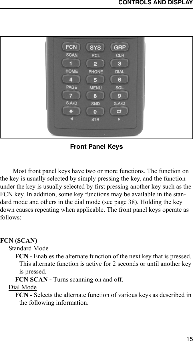
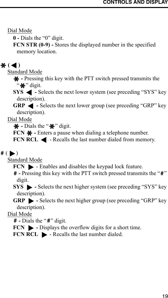
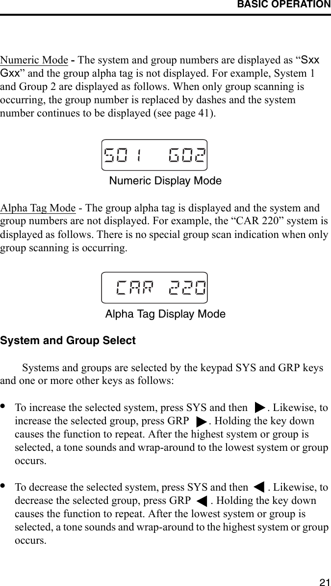
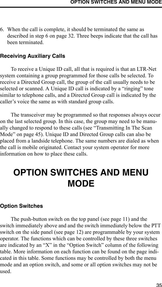
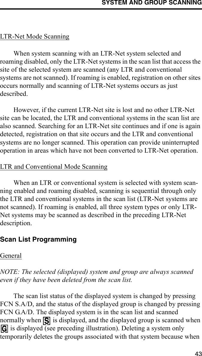
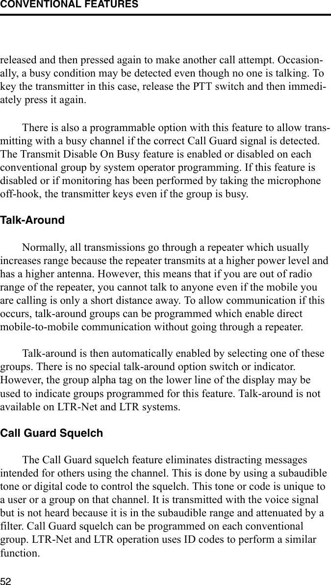
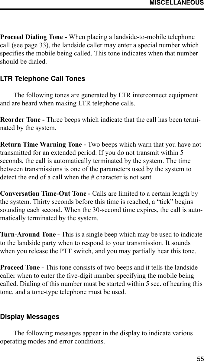
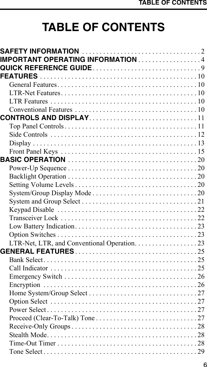
![OPTION SWITCHES AND MENU MODE36Menu ModeIntroductionThe menu mode is selected by pressing FCN MENU. Functions which can be controlled by the menu mode are indicated by an entry in the “Menu Items” column of the preceding table. More information on each function can be found on the page indicated in this table. Parameters are not displayed in the menu mode if they are not used, in a fixed state, or controlled by only an option switch. Calls cannot be received or trans-mitted while the menu mode is selected.Using Menu ModeA flowchart of the menu mode is shown on the next page. Proceed as follows to select functions using the menu mode:1. Select the menu mode by pressing FCN MENU. The first menu param-eter is then displayed.Menu Mode and Option Switch FunctionsFunction Menu Items Option SwitchSee Descrip. on PageBank select BANK SEL X 25Emergency sys/grp select X 26Encryption on-off ENCRYPT X 26Option select OPTION X 27Roaming on-off [1] ROAMING X 48Scan type select SCN TYPE 41Scan continue on-off SCN CONT 44Scan list save mode SCN SAVE 43Stealth mode select STEALTH 28Tone type select TONES 29NOTES: Functions left blank are not available.[1] Available with LTR-Net operation only.](https://usermanual.wiki/E-F-Johnson/2427240.User-Manual/User-Guide-120296-Page-36.png)