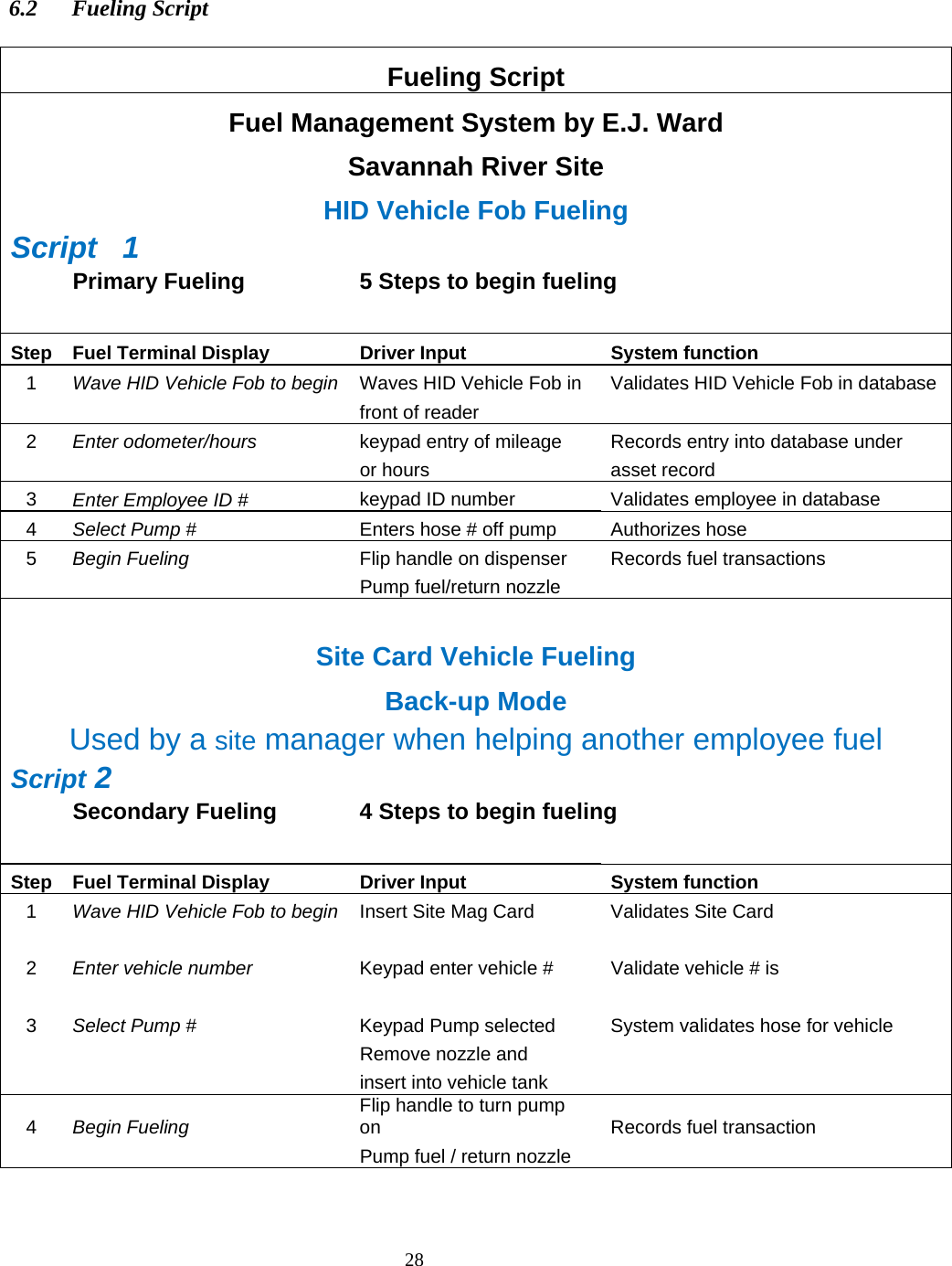
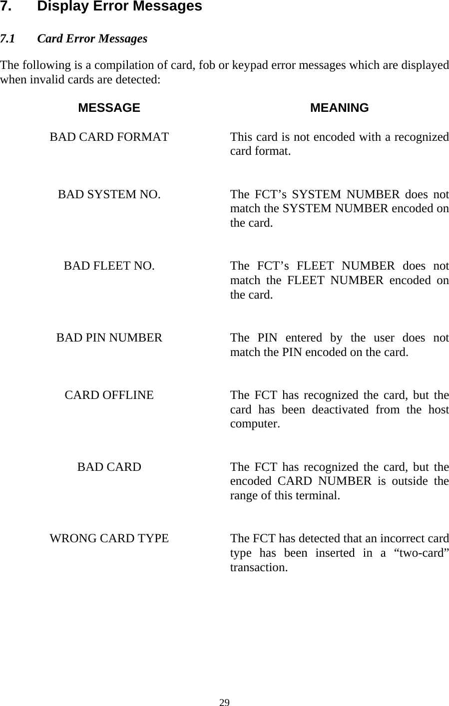
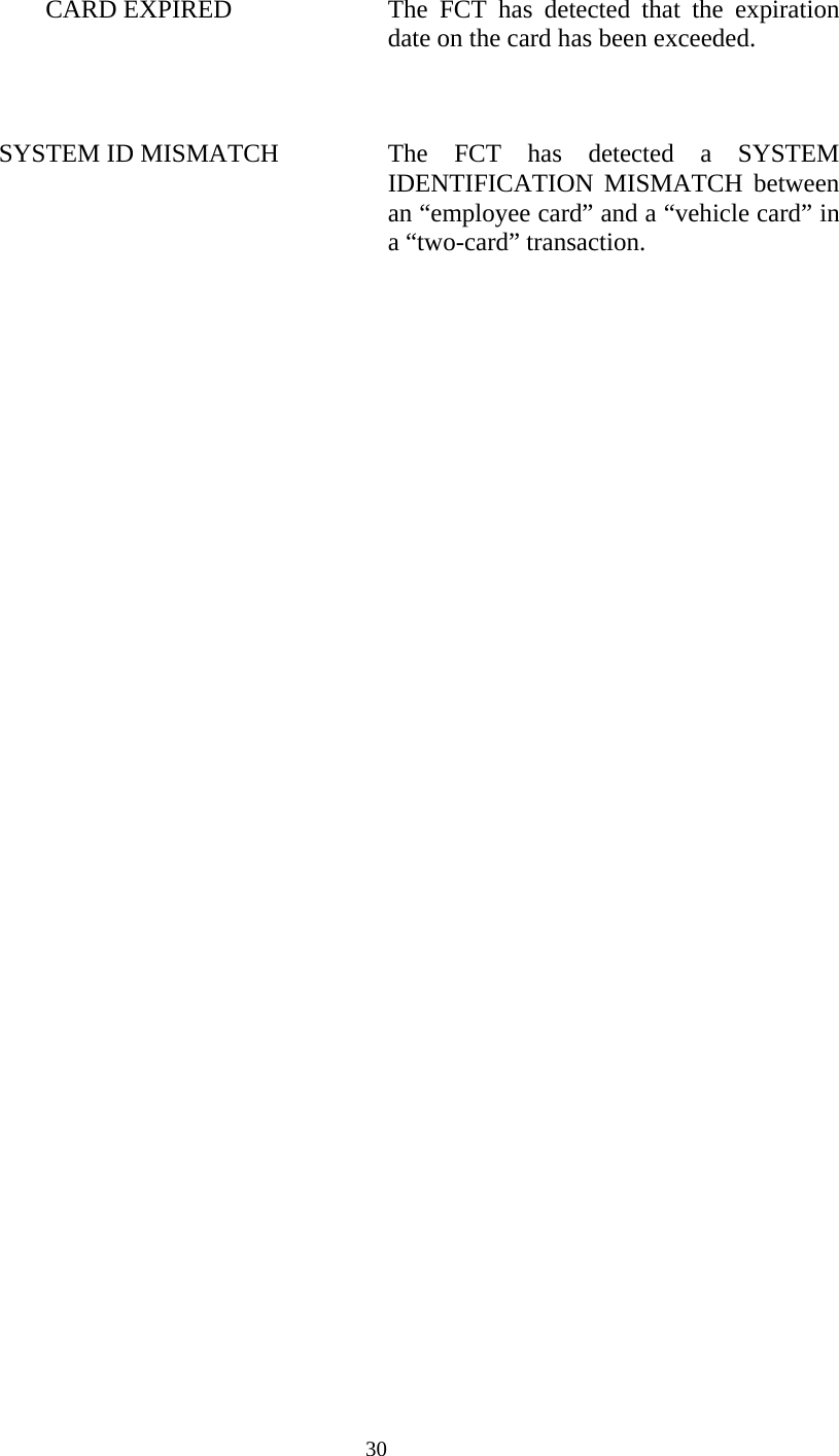
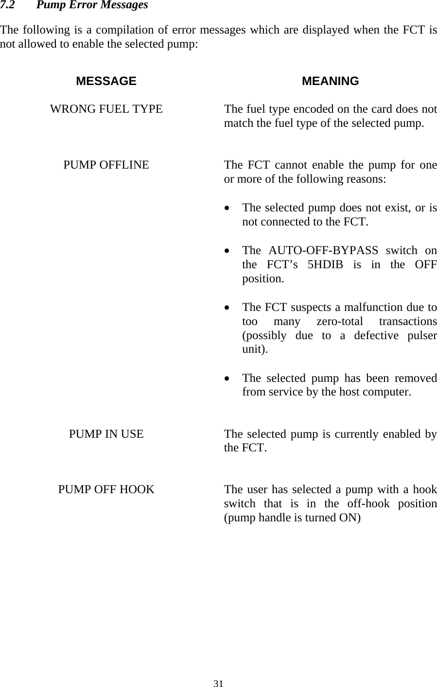
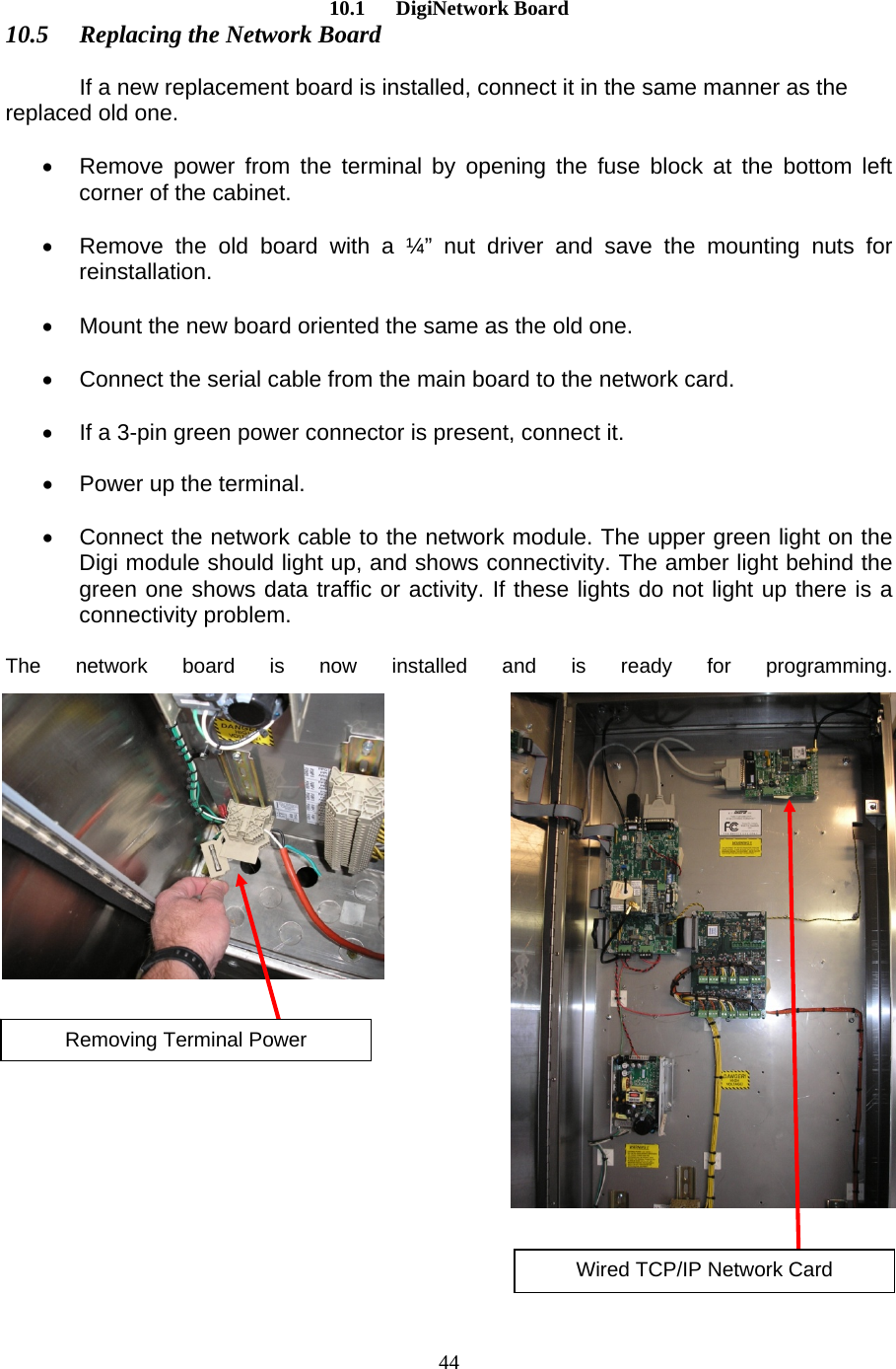
E J Ward FCT-900M RF fuel control terminal User Manual FCT Terminal Guidex

E.J. Ward, Inc. RF fuel control terminal FCT Terminal Guidex

User manual

 E.J.WARDINC.FuelControlTerminalServiceGuideAdvancedTechnologywithProvenPerformance7/28/2010
 1-1
 NOTICE     The following terms are used throughout this service guide to call attention to the presence of hazards of various risk levels, or to other important information concerning the product:    DANGER   indicates the presence of a hazard which will cause death,           severe personal injury, or substantial property damage if         ignored.   WARNING   indicates the presence of a hazard which can cause death,           severe personal injury, or substantial property damage if         ignored.   CAUTION    indicates the presence of a hazard which will or can cause         minor personal injury or substantial property damage if         ignored.   NOTICE    indicates special instructions not related to personal injury        hazards.    It is important that this service guide be thoroughly read and understood before attempting any service on the FUEL CONTROL TERMINAL (FCT). THESE TERMS ARE IMPORTANT AND ARE TO BE TAKEN SERIOUSLY - READ THEM!    FAILURE TO FOLLOW THESE GUIDELINES CAN RESULT IN DEATH, SEVERE PERSONAL INJURY, OR SUBSTANTIAL PROPERTY DAMAGE!
 1-3IMPORTANT    This device complies with part 15 of the FCC Rules.  Operation is subject to the following two conditions: (1) this device may not cause harmful interference, and (2) this device must accept any interference received, including interference which may cause undesired operation.  NOTE  This equipment has been tested and found to comply with the limits for a Class A digital device, pursuant to Part 15 of the FCC Rules.  These limits are designed to provide reasonable protection against harmful interference in a commercial environment.  This equipment generates, uses, and can radiate radio frequency energy and, if not installed and used in accordance with the instructions, may cause harmful interference to radio communications.  Operation of this equipment in a residential area is likely to cause harmful interference in which case the user will be required to correct the interference at owner’s own expense.  DANGER  Hazardous voltages are present inside the FCT cabinet.  Remove all power    before servicing!  WARNING Consult this service manual before attempting any service procedures on    the FCT.  Any servicing of the FCT must be performed solely by personnel who are trained and qualified to do so.  WARNING Take all necessary precautions when working around hazardous materials      and in hazardous areas.  Follow applicable electrical codes. Do not use      electrically powered tools or equipment when in a hazardous location.  If      you are unsure of actions, consult local authorities.  WARNING Failure to comply with all safety requirements can result in death, severe      personal injury, or substantial property damage.  NOTICE  Specifications and/or installation instructions are subject to change.
 1-4 TableofContents1.INTRODUCTION.................................................................................................................................62.FUEL CONTROL TERMINAL WARRANTY..................................................................................73.FUEL SYSTEM OVERVIEW .............................................................................................................8THE FUELING SYSTEM......................................................................................................................................83.1HOST COMPUTER .................................................................................................................................93.2FUEL SITE.............................................................................................................................................93.3ELECTRONIC ACCESS MEDIA .............................................................................................................103.4COMMUNICATIONS.............................................................................................................................103.5DOWNLOAD PARAMETERS .................................................................................................................113.6FUELING PROCESS..............................................................................................................................123.7FUELING AUTHORIZATION .................................................................................................................133.8PUMP LOGIC.......................................................................................................................................143.9THE FUEL CONTROL TERMINAL .........................................................................................................164.FCT POWER REQUIREMENTS .....................................................................................................194.1FCT POWER SPECIFICATION - 120VAC .............................................................................................194.2GROUND.............................................................................................................................................194.3AC VOLTAGE CHECK PROCEDURE.....................................................................................................214.4DC VOLTAGE CHECK PROCEDURE.....................................................................................................224.5POWER SUPPLY TROUBLESHOOTING ..................................................................................................235.FCT START-UP..................................................................................................................................245.1START-UP MESSAGES ON FCT’S WITHOUT AN OPERATING SYSTEM...........................................245.2DOWNLOADING AN OPERATING SYSTEM.....................................................................................266.CARD TYPES......................................................................................................................................276.1E.J. WARD INC. FORMATTED CARDS...................................................................................................276.2FUELING SCRIPT.................................................................................................................................287.DISPLAY ERROR MESSAGES........................................................................................................297.1CARD ERROR MESSAGES....................................................................................................................297.2PUMP ERROR MESSAGES....................................................................................................................318.BYPASS OPERATION.......................................................................................................................328.1SWITCHING TO BYPASS ......................................................................................................................329.REPLACING FCT HARDWARE.....................................................................................................349.1MAIN PROCESSOR BOARD REPLACEMENT .........................................................................................359.2SWITCHING POWER SUPPLY ...............................................................................................................37
 1-5.......................................................................................................................379.35-HOSE INTERFACE BOARD................................................................................................................399.4FRONT PANEL ALPHA NUMERIC KEYBOARD REPLACEMENT .............................................................409.5MAGNETIC CARD READER REPLACEMENT.........................................................................................4110.TCP/IP DIGINETWORK CARD (VERSION 1.00 9/25/2009) ...................................................4210.1PURPOSE.............................................................................................................................................4210.2FACTORY PROGRAMMED....................................................................................................................4210.3WHEN TO CLEAR THE NETWORK SETTINGS IN THE TERMINAL...........................................................4210.4RT TERMINAL TCP/IP NETWORK CARD ............................................................................................4310.5REPLACING THE NETWORK BOARD....................................................................................................4411.E.J. WARD, INC. SERVICE..........................................................................................................45
 61. Introduction  Proven Performance E.J. Ward Inc. has been the national leader in automated systems for energy management since 1974.  E.J. Ward Inc. systems are in operation all across the United States, building a solid reputation by providing technological answers to the challenge of fleet fuel management problems.   Advanced Technology E.J. Ward Inc. product development is enhanced by combining vast experience with new technologies.  Recent advances permit ever increasing amounts of information to be handled with increased speed and accuracy.  Multiple access options (cards, data keys, etc.) allow varying degrees of security and convenience.  A modular design approach allows easier installation and maintenance, as well as the ability to add options and upgrades as desired.  Today, E.J. Ward Inc. continues to focus research and development efforts on new ideas and equipment for fuel dispensing and data collection systems.   The Next Generation E.J. Ward Inc. now introduces its new advanced FCT that contains a 32-bit microprocessor with the capability to address 4000 megabytes, an optional graphics display or character display, and a full alphanumeric keypad. This new state of the art FCT communicates with based host computer systems via high speed modems.
 72.  Fuel Control Terminal Warranty  WARRANTY PERIOD: E. J. Ward Inc. (WARD) warranties the FUEL CONTROL TERMINAL and associated hardware for a period of one year from date of installation, or fifteen months from date of shipment (whichever occurs first).  The date of installation is defined as the date of Final Wiring Terminations and Operational Verification Testing (FWTOVT).     PARTS AND LABOR: WARD will replace or repair parts that have proven to be defective in material or workmanship during the warranty period, provided the parts are returned to Corporate Headquarters with transportation charges prepaid.  The replacement parts will be shipped to the customer or authorized service agent without charge.   All electronic parts and circuit boards must be individually enclosed inside of an anti-static bag and then carefully placed into a cardboard box filled with protective foam.  Damage incurred in transit is not the responsibility of WARD and is not covered under warranty.    LIMITATIONS AND EXCLUSIONS: This warranty is specifically limited to equipment which has been installed in accordance with WARD installation instructions.  This warranty is void if any unauthorized alterations or any additions are made to the equipment, or if it has been subjected to damage caused by abuse, misapplication, improper operation, accident, or acts of nature.  This warranty does not cover any indirect or consequential damages or loss of product incurred by the user.  WARD assumes no other liabilities in connection with this equipment and assumes no responsibility for any action or representation made by others.
 8 3.  Fuel System Overview  The Fueling System  A typical fueling system consists of the following configuration:  3.1  Host Computer – Contains the operating system database on which the fueling programs operate. 3.2  Fuel Sites –  Where automated FCTs authorize and record fueling transactions 3.3  Electronic Access Media –  Magnetic stripe cards, HID’s Fob & Keypad Entry 3.4 Communications – TCP/IP, Network connection through Verizon 3.5  Download Parameters –  FCT and site specific data 3.6 Fueling Process   Basic fueling Procedure 3.7  Fuel Authorization –    Creating a fuel transaction 3.8  Pump Enable Logic  Enable, Hook, Pulse Logic & time outs 3.9  The Fuel Control Terminal –  Description of FCT components
 9 3.1 Host Computer  The E.J. Ward, Inc. fueling and communication programs operate under all versions of Windows operating systems. These operating systems provide the necessary multitasking environment that gives the software the ability to monitor hundreds of locations and thousands of users.  The E.J. Ward, Inc. software packages provide comprehensive file handling to keep track of fuel inventory by site, tank, and product. The software also tracks the status of access media, storage tanks, fuel sites, pumps, and FCTs in the system as well as provides a variety of up-to-date management reports any time they are needed. The host computer communicates with all remote FCTs through a TCP/IP network interface.  The Ward Fuel System Software contains an OS, (Operating System) and configuration files that are downloaded to the FCT’s on the fuel islands. The OS defines how the FCT will operate and interface with the user. The OS for SRS is the same for all fuel site FCT’s. The configuration files contain the specific site information for each site. This consist of the number of tanks, fuel types, number of hoses and which tank each hose is  connected to, enable and between pulse timers, etc. The configuration file also contains the vehicle and employee data base that is downloaded to each FCT.   3.2 Fuel Site  Each fuel site has one FCT that communicates with the Host Computer through a network connection. The host computer down loads the FCT with an OS and configuration files specific for that FCT. The front door of the FCT also has a magnetic stripe card reader, HID Fob reader and front panel keypad for manual data entry by the user.  The FCT also interfaces with the Bennett dispensers and pumps through control and pulse wiring to authorize and account for each fueling transaction.  The SRS fuel sites consist of the following hardware:  • E.J. Ward, Inc. automated RT-FCT. • Bennett Mod. 3711 unleaded and diesel dispensers and ethanol suction pumps. • Fuel storage tanks, in-ground for undead and diesel, above ground for ethanol. • TCP/IP network communications. • Veeder-Root TLS-350, Tank Monitoring System, (Stand alone).
 10 3.3 Electronic Access Media  As mentioned above the host computer contains a vehicle data base and an employee data base. Each of these data bases can contain thousands of records. These records start with the number (1), and will go as high as the number of vehicles and employees as needed. The number of records can be increased in the future as needed.    SRS does not use vehicle cards with this new system, the vehicles use a “Fob”, sometimes referred to as a “Key Fob”. Each fob has a specific number assigned to it which represents a record number in the vehicle data base. Vehicle data, such as vehicle number, fuel type, gallons limit, etc. are entered in the record for that vehicle. The fob number representing the record number the vehicle is assigned to.  Employees do not use cards or fobs. However, their employee information is entered into a record in the employee data base, just as vehicle information is entered in a record in the vehicle data base. When fueling a vehicle they will enter their employee number through the front panel keypad using a keypad entry.  The host computer also contains a “Site Card” file. This is a very small file. The site cards are assigned to fueling attendants or supervisors. They are used for authorizing a fuel transaction for a vehicle that has a fob that doesn’t work or has been lost or misplaced. (The vehicle has to be on-line for this operation)  On the front panel of the FCT there is a digital display for displaying operating instructions, a magnetic stripe card reader, an HID fob reader, an alpha numeric keypad for data entry and a beeper for audio acknowledgement of data entry.   3.4 Communications  The fuel system computer communicates to the RT-FCT’s on the fuel islands through a TCP/IP network interface. Verizon provides the communication link from end to end. Verizon provides a DSL box and a network switch in the FCT cabinet that interfaces with the network card in the FCT. The fuel system computer initiates all communication from the computer to the FCT’s on the fuel islands.
 11 3.5 Download Parameters  Download parameters are the parameters sent to the FCT from the host computer. These parameters consist of an Operating System (OS) and a configuration file (config file).  The “OS” is a program that defines the operation of the FCT. How the FCT handles a fueling transaction, user prompt’s etc.  The config file contains some of these following parameters. • Sys ID, (System Identification Number)  • Fleet number • Time • Date • Maximum transaction limit • Transaction call in amount • Vehicle HID key fob data file • Employee data file • Administrative (site) card data file • Number of active hoses, fuel type, ON & OFF line status • Dispenser pulse rates (10:1, ten pulses per gal) • Enable and between pulse time outs  The host computer communicates with the FCT with either a Full Connect or a Quick Connect procedure.  Full Connect: The fuel system computer performs a full connect with the FCT during the startup procedure when an FCT is first put into service, or whenever a complete down load is required by the FCT. The OS & “config file are both down loaded to the FCT at this time.  Quick Connect: The fuel system computer retrieves any transactions that may be stored in the FCT and then sends any changes in the config files.
 12 3.6 Fueling Process  The FCT is designed to interface to all electro-mechanical fuel dispensers and pumps including the Bennett Model 3711 as installed at SRS.  The FCT controls the authorize circuit to the Bennett Model 3711 through the FCT 5-HPIB. When a user has entered valid data and qualifies for fuel authorization, the FCT activates a relay on the 5-HDIB which turns on the pump enables circuit in the FCT.  The user then takes the hose off of the dispenser/pump and puts it in the tank fill of the vehicle and turns the handle on. This sends an off hook logic to the FCT. This logic is sent back to the dispenser/pump authorization circuit which causes the register to go through reset. After the reset is complete the hose is turned on and ready for fueling.   As fuel flows through the nozzle, the dispenser pulser transmits quantity information to the FCT’s 5-HDIB in the form of electrical pulses. The dispenser/pump sends pulses to the FCT at a 10:1 ratio, (Ten pulses per gallon).  When fueling is complete the user turns the hose lever off and hangs the hose up. This turns off the dispenser/pump and the off hook logic to the FCT. The FCT detects that the transaction is complete and turns off enable and stores that transaction.
 13 3.7 Fueling Authorization  The FCT interfaces with the Bennett Mod 3711 dispenser and pump to control the authorization and accounting of a fueling transaction. The following criteria are typically required by the FCT to authorize a fueling transaction.    There are two ways to authorize a vehicle fueling transaction.  Vehicle “Fob” Authorization: The driver must use a valid key-fob from the vehicle being fueled. 1. To began, wave the vehicle fob in front of the HID reader on the front door of the FCT.  (Follow directions on display) 2. Enter odometer reading, then push enter 3. Enter employee number, then push enter 4. Select pump, then push enter 5. Remove hose from dispenser/pump, insert in tank fill 6. Turn dispenser/pump handle on and begin fueling 7. When finished fueling, turn dispenser/pump handle off and hang nozzle up  Site Card Authorization: Used by supervisors to fuel a vehicle that has a fob that is not working or lost. The vehicle data must be in the vehicle data base and turned on for this process. 1. To begin, insert site card into mag card reader on the front door of the FCT.  (Follow directions on display) 2. Enter vehicle number, then push enter 3. Enter odometer number, then push enter 4. Select pump, then push enter  5. Remove hose from dispenser/pump, insert in tank fill 6. Turn dispenser/pump handle on begin fueling 7. When finished fueling, turn dispenser/pump handle off and hang nozzle up  If the above criteria have been met, the selected hose will be turned on (enabled) and the user will have up to one (1) minute to begin fueling.  If there were any problems with the information collected by the FCT, an appropriate error message will be displayed to inform the user why authorization was not granted.  When the user has finished fueling, the FCT will attach the current time and date to the transaction data that was collected from the user, along with the total amount of fuel that was dispensed.  The FCT will then store this fueling transaction until it is transferred to the host computer.  The FCT will continue to accumulate fueling transactions until the maximum transaction limit has been reached (1,000 transactions by default unless otherwise modified by the system administrator).
 14 3.8 Pump Logic  To process a fueling transaction there are three signals, or logics that are required between the RT-FCT and Bennett Mod. 3711. from each hose for each transaction.  Logic    =  AKA Enable   =   Authorize Hook    =   Off  Hook, ARS (After Reset) Pulse     =   Just known as pulse  The FCT interfaces with the Bennett 3711 through two terminal barriers in the FCT.   TB-2 is for control wiring interface. There are 4 wire terminal connections for each hose. PPO = Pump Power Out  This comes from the N/O contact of the enable relay on the 5-HPIB and goes to the Bennett 3711 hose authorize circuit.  PPI = Pump Power Inn  PPI & ARS are jumped together. PPI also goes to the common contact of the enable relay on the 5-HPIB. ARS = After Reset  Jumped from PPI to ARS. This provides power to the hook logic on the  5-HPIB. P/N = Pump Neutral  Return neutral from ARS to neutral in the Bennett 3711  TB-3 is for pulser wiring interface. There are 3 wire terminal connections for each hose. +12 A D/C = Not used at SRS Pulse        = +12 V D/C, Through a pull up resistor DCC        = DC Common  Enable:  After the Fueling Authorization has been approved, (see 1.7 above) the enable relay is turned on. This closes the contact between PPI & PPO allowing authorization of that hose in the Bennett 3711.    Hook: The user will remove the nozzle and place it in the vehicle tank fill and turn on the hose lever. When the hose lever is turned on the hose lever switch will send a 120 V A/C signal to PPI & ARS for that hose in the FCT. The ARS logic tells the FCT that the hose has been turned on and to start counting pulses. This 120 V also goes from PPI through the closed contact of the enable relay on the 5-HPIB to PPO and out to authorize in the Bennett 3711 for that hose. This causes the register to go through reset. After the reset function is complete the pump motor and ESV are turned on and fueling can begin. If the FCT does not see the Off Hook/After Reset logic turned on it will not count pulses and will turn off in one minute.
 15Pulse: As fuel is being dispensed the Bennett 3711 pulse circuit will close sending a pulse to the FCT at a rate of 10:1 or ten pulses per gallon.  End of Transaction: When fueling is complete and the dispenser handle is turned off. The terminal looses the Hook signal and ends the transaction by turning off the Enable and building the transaction to be sent in to the computer.  Timer Logic: There are two timers involved in a fueling transaction. An enable timer and a between pulse timer. These timers are normally set at one minute, but can be changed at the fuel system computer for any individual hose on any terminal by the fuel system operator.  Enable Timer: This timer is normally set for one minute. The enable timer stars when a fueling request is approved and the FCT displays that the pump is ready. If the FCT sees a pulse within the one minute time it will abandon, or end the enable timer and start the between pulse timer. If the terminal does not see a pulse within one minute it will turn the enable off and build a no total transaction.  Between Pulse Timer: The between pulse timer starts when the FCT sees the first pulse. This timer resets to zero after each pulse the FCT sees. If the FCT does not see a pulse within 60 second it will turn off the enable and end the transaction. This means that the fueling can be stopped at any given time any number of times as long as the 60 seconds between pulse timer does not elapse. Each time fueling starts again within the 60 seconds timer and the FCT sees a pulse the timer is reset to zero.  No Total Transaction: If the FCT sees three no totals in a row it will take that hose “Offline”. This transaction will be sent to the fuel system computer the next time the computer communicates with the FCT. The computer will take the hose off line in the terminal file a will remain “Offline” until the problem is corrected and it is turned on by the fuel system operator.   .
 163.9  The Fuel Control Terminal  The SRS configuration of the RT-FCT consists of the following hardware:  • RT-FCT Cabinet • Main Processor Board (MPB) • 5-Hose  Dispenser  Interface  Board  (5HDIB) • TCP/IP Network Board • Front Panel With Alpha Numeric Keypad • Liquid Crystal Display (LCD) With Back Light. • Front Panel Beeper • Magnetic Card Reader • HID ProxPro Proximity Fob Reader • Switching Power Supply  • TB-1: 120 V A/C, Power For RT-FCT And Duplex Plug • TB-2: RT-FCT To Dispenser/Pump Control Wiring Interface • TB-3: RT-FCT To Dispenser/Pump Pulser Wiring Interface • Network Switch, Provided By Verizon • DSL, Provided By Verizon
 17                       Figure 3-1     FCT Front Door, Out Side  Liquid Crystal Display With Back Light      Front Panel With Alpha Numeric Keypad Magnetic Stripe Card Reader HID Key Fob Card Reader Beeper
 18           Figure 3-2     FCT Front Door, Inside                         Display Cable Front Panel Cable Display Adapter Board Mag Card Reader Cable HID Card Reader Cable Beeper Cable
 19 4.  FCT Power Requirements    4.1  FCT Power Specification - 120VAC  The AC power source supplied to the FCT is recommended to be from a dedicated 120VAC, 60 Hz, 15 AMP circuit breaker.  Recommended wiring colors are as follows:       1 Black wire for HOT      1 White wire for NEUTRAL      1 Green wire for GROUND  4.2 Ground The ground wire for the FCT should be a true ground and not tied to a load carrying neutral bar. In the breaker panel that feeds the fuel island there should be a neutral bar and a ground bar. The ground bar should be fed with a separate ground wire from the main service panel, not tied in with the neutral bar. In the main breaker panel at the meter loop service there is a neutral bar and a ground bar. At this point the neutral bar, ground bar and cabinet are bonded together to a ground wire going to the ground rod for the meter service so at this point neutral and ground are the same. From the main service to the remote panel at the fuel island there should be a neutral wire tied to the neutral bar in both panels and a separate ground wire tied to the ground bar in both panels.  At the remote panel the neutral bar should not be bonded to the ground bar or the panel, (this is a load carrying neutral from this point back to the main panel). At the remote panel the ground bar should only be bonded to the panel for safety ground. The ground wire from this panel to the FCT on the fuel island should be tied to the ground lug on the relay panel.  WARNING All electrical wiring, conduit, etc. must comply with all governing local,      state, and national electrical codes.  WARNING Before applying power, the following FCT power specifications must be      observed.  Any other AC power configuration can produce dangerous and    unpredictable results. WARNING Proper conduit access into the enclosure must be observed in order to maintain a safe operating environment.  Failure to maintain proper conduit access could result in serious personal injury, death, property loss, and equipment damage through explosions, fire, or electrical shock.
 20 TB-1 is for incoming 120 V A/C power to the FCT. It is located in the lower left corner of the FCT. There are two separate fused circuits on TB-1. One circuit is for power to the FCT and the other is for power to the GFIC duplex plug which provides power to the communication equipment. The two fused circuits include barriers for the “Hot & Neutral” wires from the breaker panel.             Accessory PowerTo Duplex Plug120 VACGNDTB1RT-FCTBack PanelNEUHOTMain PowerFor RT-FCT120 VACRT-FCTCabinetNEUHOT   • Figure 4.1     TB-1: 120 V A/C, Power For FCT And Duplex Plug
 214.3  AC Voltage Check Procedure     When the FCT’s AC power is turned on, the 120VAC supply can be measured on the field terminals labeled HOT, NEU, and GND.  The AC supply should read as follows:  • Between HOT and NEUTRAL = 110VAC to 125VAC. • Between HOT and GROUND = 110VAC to 125VAC. • Between GROUND and NEUTRAL = 0VAC (nominal).       DANGER  The following procedure requires access to hazardous voltages.  Only    trained and qualified personnel should attempt this procedure.  WARNING The FCT door must be completely closed whenever fuel is being      dispensed.  Do not dispense fuel when the FCT cabinet is open. WARNING If the voltage readings are outside of the specified ranges, turn the FCT’s      AC power off and contact the proper authorities.  WARNING GROUND from the breaker serves to prevent the cabinet from becoming      an electrical shock hazard.  Do not remove this connection or otherwise    impair it’s function.
 22  4.4  DC Voltage Check Procedure   When AC power is applied to the FCT, The DC supply voltages can be measured using a hand-held multimeter.  Identify JP9, a 4-pin connector located on the bottom edge of the MPB. There are (4) test points located, just to the left of JP9 labeled to identify corresponding DC voltage assignments. With a voltmeter check the DC levels as follows: 1) Between the GND (BLK) TP and the +5V (RED) TP =  +5VDC, +/-0.1V. 2) Between the GND (BLK) TP and the +12V FUSED (YEL) TP =  +12VDC, +/-0.1V. 3) Between the GND (BLK) TP and the +12 V IN TP  = +12VDC, +/-0.1V                                      TEST POINTS                                GND              BLK                                +5V               RED                                                                                     JP9                          JP10                 +12V FUSED             YEL                           +12V IN              WHT    Figure 4.3  Edge of Main Processor Board where power connectors are located.   DANGER  The following procedure must be performed with power applied to the      FCT, therefore hazardous voltages will be present. Only trained and      qualified personnel should attempt this procedure.  WARNING The FCT door must be completely closed whenever fuel is being      dispensed.  Do not dispense fuel when the FCT cabinet is open. NOTICE  If DC voltages are not within the specified ranges there could be a power      supply problem on the MPB or a malfunction in one of the interface      boards.  All problems associated with the power supply must be resolved      before continuing with normal FCT operations.  Faulty operation may      result if power supply problems are ignored.
 23 4.5  Power Supply Troubleshooting     The DC power supply that provides the source of DC voltage for the MPB is an open frame ‘SWITCHING’ supply  All interface boards and associated external devices receive their power from the MPB via cables.  If applied AC voltage is within specification, the power supply should produce nominal DC voltages.  If the DC voltages are not within their specified ranges (refer to “DC Voltage Check Procedure”), perform the following process of elimination procedure:  1) Disconnect AC power to the FCT by opening the MAIN FUSE BLOCK (see Figure 4.1). 2) Disconnect the RED / BLK wire harness between JP9 of the MPB and the power supply. 3) Close the MAIN FUSE BLOCK and check the DC voltages at the disconnected power supply connector. 4) If the DC voltage is not within the specified range, replace the Power Supply (Refer to “Replacing FCT Hardware” section). 5) If the DC voltage is within specs, the problem interface board or peripheral device must then be identified. 6) Disconnect AC power by opening the MAIN FUSE BLOCK. 7) Reconnect the RED/BLK wire harness and disconnect all other cables between the MPB and each interface board and peripheral device. 8) Close the MAIN FUSE BLOCK and check the DC voltages at the TEST POINTS. 9) If the DC voltage is within specs, disconnect AC power. 10) Reconnect one interface board or peripheral device. 11) Close the MAIN FUSE BLOCK and check the DC voltages again.  Repeat steps 6 through 11 (each time reconnecting one additional interface board or peripheral device) until the DC voltage check FAILS. 12) If the device causing the DC voltage failure is an interface board which has additional cables connecting it to other peripheral devices, the problem must then be isolated to either the interface board itself or a connected peripheral device.  Repeat this elimination procedure on the interface board to further isolate the problem. Replace the interface board or peripheral device that forces the DC voltages out of nominal operating range. (Refer to the “Replacing FCT Hardware” section).  DANGER  Parts of the following procedure must be performed with power applied to the FCT, therefore hazardous voltages will be present. Only trained and qualified personnel should attempt this procedure.  WARNING Power to the FCT must be disconnected before performing any installation or removal of FCT hardware.  Do not connect or disconnect cables when power is applied.
 24  5. FCT Start-Up  5.1  Start-Up Messages on FCT’s without an OPERATING SYSTEM  An FCT needs to have an OPERATING SYSTEM loaded into its memory from the host computer before it can begin normal operation.  This OPERATING SYSTEM is the actual program that the FCT’s computer uses to control and record fueling transactions.  Two different start-up message modes are available on an FCT that does not have an OPERATING SYSTEM loaded.  DIP SWITCH #8 (on the MPB) controls the startup message mode.  For normal operation, DIP SWITCH #8 should be set to OFF.  If DIP SWITCH #8 is in the ON position, the following start-up messages will be displayed immediately after applying power to the FCT:  MESSAGE (DIP SWITCH #8 = ON)  MEANING  Verifying EEprom  The FCT is checking its Electrically Erasable Programmable Read Only Memory.  The basic system parameters needed for the terminal to identify itself and communicate with the host computer are stored here (this memory is also referred to as “non-volatile” memory because it stays intact when power is removed).   Terminal ID ->1  This is the FCT IDENTIFICATION NUMBER.  Enter a new IDENTIFICATION NUMBER (1 to 255), or press ENTER to keep the one which is displayed.    System # -> 2  This is the FCT’s SYSTEM NUMBER.  Enter a new SYSTEM NUMBER (0 to 9), or press ENTER to keep the one which is displayed.   Fleet # -> 34  This is the FCT’s assigned FLEET NUMBER.  Enter a new FLEET NUMBER (1 to 99), or press  ENTER to keep the one which is displayed.
 25Protocol = 1 0: UNIX     1:WIN95  This setting informs the FCT of what type of operating system the host computer is using.  Enter “0” if the FCT will be communicating with a UNIX based system, or “1” if it will be communicating with a WINDOWS 95 based system. Press ENTER to keep the setting which is displayed.     WAITING FOR A CALL FROM THE HOST...    *  This message will be displayed only if the “Term dials out?” setting is set to “N”.  It signifies that the FCT is ready and is waiting to receive a call from the host computer.           MESSAGE (DIP SWITCH #8 = OFF)  MEANING  Verifying EEprom  The  FCT  is checking its Electrically Erasable Programmable Read Only Memory.  The basic system parameters needed for the terminal to identify itself and communicate with the host computer are stored here (this memory is also referred to as “non-volatile” memory because it stays intact when power is removed).     WAITING FOR A CALL FROM THE HOST...    *  This message will be displayed only if the “Term dials out?” setting is set to “N”.  It signifies that the FCT is ready and is waiting to receive a call from the host computer.
 265.2  Downloading an OPERATING SYSTEM  The FCT is ready to receive an OPERATING SYSTEM when the “WAITING FOR A CALL FROM THE HOST...” or “CALLING HOST.....” message is displayed.  When communication with the host computer is established, the FCT will request an OPERATING SYSTEM DOWNLOAD.  The host computer will acknowledge by transmitting the OPERATING SYSTEM to the FCT.  Below is a typical OPERATING SYSTEM DOWNLOAD sequence.  MESSAGE MEANING  RECEIVED CALL FROM THE HOST.....  This message indicates that the FCT has established communication with the host computer.   DOWNLOADING SYSTEM PLEASE WAIT.....  The FCT is in the process of receiving the OPERATING SYSTEM from the host computer.  It will take a few minutes to complete this operation.   DOWNLOADING COMPLETE WAITING REBOOT  The FCT has received the OPERATING SYSTEM and is preparing to start normal operation.  The display will go blank for a few seconds following this message while the FCT’s computer resets.   TERMINAL OFFLINE Reason: CONFIGURATION  This message indicates that the FCT has started the OPERATING SYSTEM, but is still missing some necessary configuration data.  The FCT will now request this data from the host computer.  Normal operation will begin immediately after the data is received.   WAVE HID VEHICLE FOB TO BEGIN  The FCT is now ready for normal operation.   Refer to the TROUBLESHOOTING SECTION of this manual if there are any problems DOWNLOADING the OPERATING SYSTEM.
 276. Card Types  6.1  E.J. Ward Inc. formatted cards  As stated in section 1.4, SRS uses three different card types. The fuel system computer contains the three types of card files and downloads this data to the RT-FCT’s.   • Card Type 1 is a “Vehicle FOB”. The Fob contains the system ID and the card number in the vehicle data file that the vehicle is assigned to. All other information associated with the vehicle is stored in the vehicle card file in the fuel system computer and is downloaded to the terminal stored in the terminal vehicle data base. This information consists of the fuel type, gallons limit, odometer reading, etc. that is associated with the vehicle.  • Card Type 4 is a “Sight Card” which is assigned only to authorized personnel (such as site Managers, etc.) who are allowed to access fueling for a vehicle with a missing or defective fob. The vehicle must be in the system and must be authorized for fueling.  • Card Type 6 is a “Employee Card” which is assigned to an employee who is authorized to fuel a vehicle that has a vehicle fob. This concept is known as a “two-card” system.  In a “two-card” system, the employee is required to enter both the “Employee Number in the RT-FCT keypad” and wave the “Vehicle Fob” before authorization will be granted.  (See Fueling Script Below)
 28  6.2  Fueling Script  Fueling Script Fuel Management System by E.J. Ward Savannah River Site HID Vehicle Fob Fueling Script   1  Primary Fueling  5 Steps to begin fueling     Step  Fuel Terminal Display  Driver Input  System function 1  Wave HID Vehicle Fob to begin  Waves HID Vehicle Fob in  Validates HID Vehicle Fob in database       front of reader    2  Enter odometer/hours  keypad entry of mileage  Records entry into database under       or hours  asset record 3  Enter Employee ID #  keypad ID number  Validates employee in database 4  Select Pump #  Enters hose # off pump  Authorizes hose 5  Begin Fueling  Flip handle on dispenser  Records fuel transactions       Pump fuel/return nozzle      Site Card Vehicle Fueling Back-up Mode Used by a site manager when helping another employee fuel Script 2  Secondary Fueling  4 Steps to begin fueling     Step  Fuel Terminal Display  Driver Input  System function 1  Wave HID Vehicle Fob to begin  Insert Site Mag Card   Validates Site Card            2  Enter vehicle number  Keypad enter vehicle #  Validate vehicle # is       3  Select Pump #  Keypad Pump selected  System validates hose for vehicle    Remove nozzle and        insert into vehicle tank    4  Begin Fueling  Flip handle to turn pump on Records fuel transaction       Pump fuel / return nozzle
 297. Display Error Messages  7.1  Card Error Messages   The following is a compilation of card, fob or keypad error messages which are displayed when invalid cards are detected:  MESSAGE MEANING  BAD CARD FORMAT  This card is not encoded with a recognized card format.   BAD SYSTEM NO.  The  FCT’s  SYSTEM NUMBER does not match the SYSTEM NUMBER encoded on the card.   BAD FLEET NO.  The FCT’s FLEET NUMBER does not match the FLEET NUMBER encoded on the card.   BAD PIN NUMBER  The PIN entered by the user does not match the PIN encoded on the card.   CARD OFFLINE  The FCT has recognized the card, but the card has been deactivated from the host computer.   BAD CARD  The FCT has recognized the card, but the encoded CARD NUMBER is outside the range of this terminal.   WRONG CARD TYPE  The FCT has detected that an incorrect card type has been inserted in a “two-card” transaction.
 30CARD EXPIRED  The FCT has detected that the expiration date on the card has been exceeded.   SYSTEM ID MISMATCH  The FCT has detected a SYSTEM IDENTIFICATION MISMATCH between an “employee card” and a “vehicle card” in a “two-card” transaction.
 317.2  Pump Error Messages  The following is a compilation of error messages which are displayed when the FCT is not allowed to enable the selected pump:   MESSAGE MEANING  WRONG FUEL TYPE  The fuel type encoded on the card does not match the fuel type of the selected pump.   PUMP OFFLINE                 The FCT cannot enable the pump for one or more of the following reasons:  • The selected pump does not exist, or is not connected to the FCT.  • The AUTO-OFF-BYPASS switch on the FCT’s 5HDIB is in the OFF position.  • The FCT suspects a malfunction due to too many zero-total transactions (possibly due to a defective pulser unit).  • The selected pump has been removed from service by the host computer.   PUMP IN USE  The selected pump is currently enabled by the FCT.   PUMP OFF HOOK  The user has selected a pump with a hook switch that is in the off-hook position (pump handle is turned ON)
 328. Bypass Operation  Unexpected problems may develop that interrupt the automatic processes of the fuel site, which can range anywhere from worn out parts in a fuel dispenser to user entry errors at the host computer. In the event that a FCT is unable to automatically enable a fuel dispenser due to some sort of malfunction, a temporary solution is provided by the use of internal AUTO-OFF-BYPASS switches.  8.1  Switching to Bypass  Locate the miniature 3-position AUTO-OFF-BYPASS switch for the desired pump number and move the switch from the AUTO position, through the OFF position, to the BYPASS position.  When the AUTO-OFF-BYPASS switch has been placed into the BYPASS position, the small red “pump enable” light will illuminate, indicating that the PUMP ENABLE RELAY is energized for that particular pump.  Be sure to close the door before resuming fueling operations.  The FCT will generate a BYPASS TRANSACTION and record the amount of fuel dispensed in order to maintain fuel reconciliation. Although the FCT will continue to account for fuel usage during a BYPASS operation, it is highly recommended that the original problem that prompted the BYPASS operation be resolved as soon as possible. It is also recommended that a fuel attendant should be assigned to the fuel site to manually record all fueling transactions.   Each manual fueling transaction should contain:  • Time & date • Pump # • Vehicle # and/or vehicle card # • Odometer • Total  gallons  Manually recorded fueling transactions can be entered into the host computer at a later date to reconcile the fueling system programs and tank balances.   DANGER  If the following procedure is performed with power applied to the FCT,  hazardous voltages will be present. Only trained and qualified personnel should attempt this procedure.  WARNING The FCT door must be completely closed whenever fuel is being dispensed.  Do not dispense fuel when the FCT cabinet is open.
 33                               Figure 8.1- The Five Hose Dispenser Interface Board (5HDIB) has a dedicated BYPASS switch for each pump. Pulse Wire Connector  Hose 1 & 2 Hook Wire Connector Hose 1 & 2 Enable Wire Connectors Hose 1 & 2 Pulser LED’s Hose 1 & 2 Hook Led’s Hose 1 & 2 Enable Relay Hose 1 & 2 Enable LED’s Hose 1 & 2 Bypass Switch Hose 1 & 2 1  2 3  4 5
 34 9.  Replacing FCT Hardware   WARNING Power to the FCT must be disconnected before performing any installation or removal of FCT hardware. Do not restore AC power until procedure is complete and all connections have been verified.  WARNING AC power may also be supplied to the 5HDIB and solid state relay assembly (if equipped) from the dispensers.  Turn off dispenser circuit breakers before servicing.  WARNING The FCT door must be completely closed whenever fuel is being dispensed.  Do not dispense fuel when the FCT cabinet is open.  CAUTION As with most modern electronic hardware, the devices used in the construction of the FCT circuit boards are subject to damage by static electricity.  Always keep circuit boards inside anti-static bags when not in use.  It is recommended that personnel working with the FCT “ground” themselves by touching an electrically grounded object just prior to handling circuit boards.
 359.1  Main Processor Board Replacement         Figure 9.1  Main Processor Board    JP-2 JP-20 JP-3 JP-5 JP-13 JP-8 JP-10 JP-9 JP-19 JP-6 JP-16 JP-18 JP-15 JP-22 JP-25 JP-14 JP-26 JP-21 Reset Button Dip Switch LED Heart Beat Test Points             Gnd - Blk            +5V - Red  +12V Fused - Yel    +12 V In - Wht JP-9 & JP-10 Pin Out’s
 36• JP3 Dispenser Interface - connects to 5HDIB.   • JP5 VIT Interface - connects to the FCTI. • JP6 Network Interface - connects to the Network Interface Board. • JP16 LCD - connects to the Front Panel display.  • JP18 KEYBOARD - Connects to the Front Panel keypad. • JP19 CARD READER-– Connects to the Front Panel MAGNETIC CARD reader. • JP20 KEY READER – Connects to the Front Panel DATA KEY reader. • JP8 Dry Contact Inputs - connects to the Intrusion Switch. • JP9 +12VDC input to MPB. • JP10 (+12VDC) – This is a fused AUXILLARY output that can be connected to Interface Boards, which are not powered directly thru the MBD. • JP21 Used as a programming port for the Front Panel Interface IC – U24. • JP15 TLS - connects to an external Tank Monitor (TLS) using support RS- 232 communications.  • JP22 Jumper - Used to select state of PIN 9 of JP15. • JP13 Auxiliary Outputs - use for controlling optional devices. • JP2 Modem Port - serial RS232 DB9 port connects to an OEM modem. • JP25 Jumper – Used to select state of PIN 22of JP2. • JP26 CSI ENABLE – Install jumper for NORMAL operations.  • JP14 - JP13 power source - INT = +12VDC from MPB,  EXT = external DC voltage supply. • LED - Flashing red light indicates that the MPB is operating properly. • Reset Button - press to clear unusual problems and to restart the FCT program. • Dip Switch - Positions 1,2,3 & 4 configure the FCT’s Network Address for multiple FCTs.  Normal setup is #1=OFF, #2=ON,#3=ON ,#4=ON.  Switch #8 is used only for debug purposes and should be kept OFF.   1) Disconnect AC power to the FCT by opening the MAIN FUSE BLOCK. 2) Carefully unpack the new MPB and check for shipping damage. Inspect the edge connectors and straighten any bent connector pins. 3) Set the dip switches on the new MPB to the same setting as the dip switch settings on the old MPB. 4) Set JP22, JP25, JP14, and JP26 to same position as on the old MPB. 5) Disconnect all cables and all interface boards from the old MPB . It is not necessary to disconnect cables that are plugged into the interface boards. Allow the interface boards to hang by the device cables they are connected to while changing out the MPB. 6) Transfer mounting hardware from the old MPB to the new MPB as required.  Do not omit any mounting hardware. 7) Place the old MPB into the anti static bag that came with the new MPB. 8) Install the new MPB into the FCT cabinet.  Reconnect all cables and interface cards.  9) Perform a final inspection of all the cable connections, interface boards, jumpers, switches, etc.. 10) Restore AC power and check for proper operation.
 37  9.2  Switching Power Supply   1) Disconnect AC power to the FCT by opening the Main Fuse Block. 2) Disconnect the wiring harness connector on the Power Supply from the MPB. 3) Disconnect the wiring harness connector on the Power Supply from the AC Power. 4) Unscrew the mounting screws from the Power Supply and remove it from the back panel. 5) Install the new Power Supply on the back panel, in exactly the same position. 6) Reconnect the new Power Supply wiring harness connectors. 7) Verify correct installation of the Power Supply before continuing. 8) Restore AC power and check for proper operation.          Figure 9.2 Switching Power Supply WARNING Incorrect installation of the POWER TRANSFORMER may result in faulty operation in addition to possible explosion, fire, and electrical shock hazards. Switching Power Supply Wiring Harness Connector from MPB Wiring Harness Connector  Main Fuse Block RT-FCT AC Power
 38      Figure 9.3      Five Hose Dispenser Interface Board  WARNING AC power may also be supplied to the 5HDIB and solid state relay assembly (if equipped) from the dispensers.  Turn off dispenser circuit breakers before servicing.
 399.3  5-Hose Interface Board  1) Disconnect AC power to the FCT by opening the MAIN FUSE BLOCK. 2) Turn off the circuit breaker(s) supplying power to the dispensers. 3) Carefully unpack the new 5HDIB from the anti-static bag and check for shipping damage.  Inspect each of the edge connectors and straighten any bent connector pins. 4) Identify the jumper JP2, JP13, JP14, JP23, JP24, JP29 on the new 5HDIB and configure them the same as on the 5HDIB to be replaced.  Note that JP29 will be installed on the 5HDIB that controls dispensers 1-5, and omitted on the 5HDIB that controls dispenser 6-10. 5) All dip switches should be in the OFF position. 6) Disconnect the MPB interface cable. 7) Carefully disconnect each of the dispenser cable plugs from their sockets. Do not stretch or reshape any of the wiring harnesses to the 5HDIB. 8) Remove the old 5HDIB from the stand-offs and insert it directly into the anti-static bag that the new 5HDIB came in. 9) Mount the new 5HDIB onto the stand-offs and reconnect all cables.  Match the labels on each dispenser cable connector to the silk screen labeling located on the 5HDIB next to each JP socket. 10) Place each Auto-Off-Bypass switch into the AUTO position. 11) Verify correct installation of the 5HDIB and all cables, connectors, jumpers and switches before continuing. 12) Restore AC power to the FCT and the dispensers.  Check for the proper operation of each dispenser.
 40 9.4  Front Panel Alpha Numeric Keyboard Replacement      Figure 9.4      Front view of the Front Panel Alphanumeric Keyboard with graphic LCD and magnetic card reader.       Figure 9.5      Rear view of the Front Panel Alphanumeric Keyboard with an alphanumeric LCD.  1) Disconnect AC power to the FCT by opening the MAIN FUSE BLOCK. 2) Disconnect the beeper cable.  If the replacement keyboard panel does not have a beeper installed, transfer the beeper from the old keyboard to the new keyboard. 3) Disconnect the keyboard cable from the keyboard cable extension.
 414) Refer to the section on “Magnetic Card Reader Replacement” and remove the card reader from the keyboard panel. 5) Refer to the section on “Display Replacement” to remove the display assembly from the keyboard panel. 6) Remove all 10 mounting nuts from each of the studs on the keyboard panel.  Remove the old keyboard from the cabinet door. 7) Transfer any necessary hardware from the old keyboard panel to the new keyboard panel (stand-offs, display bezel, etc.). 8) Mount the new keyboard onto the FCT cabinet door. 9) Re-install the display assembly and card reader.  Do not omit any hardware.  Re-connect all cables, maintaining proper cable routing to prevent cables from becoming “pinched” in the cabinet door. 10) Verify correct installation of all hardware.  Make sure all cables are plugged into their sockets correctly.   11) Restore AC power to the FCT and check for proper operation.   9.5  Magnetic Card Reader Replacement   1) Disconnect AC power to the FCT by opening the MAIN FUSE BLOCK. 2) Before disconnecting the card reader ribbon cable, observe the cable orientation. 3) Remove all 4 screws from the card reader and pull the card reader out from the front of the keyboard panel. 4) Mount the new card reader into the keyboard panel. 5) Connect the card reader ribbon cable to the new card reader, taking care to maintain proper cable orientation. 6) Restore AC power to the FCT and check for proper operation.
 42 10.  TCP/IP DigiNetwork Card (Version 1.00 9/25/2009)  10.1 Purpose  This guide is for the installation of replacement RT terminal Digi network cards and programming new RT terminals equipped with a Digi Network card. This network board may communicate at either 10/T or 10/100 speed and will auto select the speed in accordance with the router it is connected to.  10.2 Factory Programmed  The RT terminal and replacement network boards come from the Ward factory “set up and ready to program” with the customers IP address. If this is a new terminal, skip to the configuration section of these instructions. If the customer’s IP address settings are known at the time the equipment or replacement board is ordered, Ward will program these settings at the factory for a setup fee.  10.3  When to Clear the Network Settings in the Terminal  Normally clearing the network card is not needed. The network settings are cleared by holding the reset button down on the network module while powering up the terminal. The directions for clearing the network settings are outlined at the end of this guide starting at page 13. If the network card is new or refurbished from the Ward factory, it is ready for programming and will not need to be cleared. The only case where a network card should be cleared is when it will not communicate to the Digi Device Discovery program.
 43  10.4  RT Terminal TCP/IP Network Card  The parts of the network card are labeled in the photo above. Refer to this photo to identify different parts of the network board as they are mentioned in the guide below. The network card consists of a communications carrier board with a wired Digi network module mounted to it. The Digi Device Discovery software identifies this card by the MAC address on the label attached to the module. The Network status lights show the status of the network connections and the modem/serial lights show the actual communication status to the main board. Some terminals use the green power connector to power the terminal while newer terminals power the card through the serial cable. The black carrier board reset button resets the carrier board but does not reset the Digi module. Therefore pressing the black reset button on the carrier board will not erase the network card’s settings. The Digi module’s settings can only be reset to default by depressing the tiny button on the module itself while powering up the board.                   Network Module Reset Button Network Module Communication Carrier Board Green 12-VDC power connector Black Carrier Board Reset Button MAC Address Label Serial Port to Main Board Network Port Network Status Lights Modem/Serial Status Lights
 4410.1      DigiNetwork Board 10.5  Replacing the Network Board   If a new replacement board is installed, connect it in the same manner as the replaced old one.   •  Remove power from the terminal by opening the fuse block at the bottom left corner of the cabinet.  •  Remove the old board with a ¼” nut driver and save the mounting nuts for reinstallation.  •  Mount the new board oriented the same as the old one.  •  Connect the serial cable from the main board to the network card.   •  If a 3-pin green power connector is present, connect it.  •  Power up the terminal.  •  Connect the network cable to the network module. The upper green light on the Digi module should light up, and shows connectivity. The amber light behind the green one shows data traffic or activity. If these lights do not light up there is a connectivity problem.  The network board is now installed and is ready for programming.Removing Terminal Power Wired TCP/IP Network Card
 45 11.  E.J. Ward, Inc. Service   For any questions related to:  • Troubleshooting malfunctions • Ordering new replacement hardware • Upgrading existing hardware or firmware • Installation of new FCTs • Host computer related problems    Please call or write to:  E.J. Ward, Inc. 8801 Tradeway San Antonio, Texas 78217  1-800-580-9273 (24 Hour Service) (210)-824-2031 (Fax)                                         support@ejward.com

Navigation menu