E Measuring Device USB01 DIGITAL MEASURING TAPE WITH USB RF RECEIVER User Manual USERS MANUAL
E Measuring Device Limited DIGITAL MEASURING TAPE WITH USB RF RECEIVER USERS MANUAL
USERS MANUAL

Garment Inspection and Reporting System
成衣检测及报表系统 GS-188
用戶手冊
1
Warning:
Changes or modifications to this equipment and/or program not expressly approved by the party
responsible for compliance could void the user authority to operate the equipment.
NOTE:
T HIS DEVICE COMPLIES WITH PART 15 OF THE FCC RULES. OPERATION IS SUBJECT TO THE
FOLLOWING TWO CONDITIONS: (1) THIS DEVICE MAY NOT CAUSE HARMFUL INTERFERENCE, AND
(2) THIS DEVICE MUST ACCEPT ANY INTERFERENCE RECEIVED, INCLUDING INTERFERENCE THAT
MAY CAUSE UNDESIRED OPERATION.
This equipment has been tested and found to comply with the limits for a Class B digital device,
pursuant to Part 15 of the FCC Rules. These limits are designed to provide reasonable protection
against harmful interference in a residential installation. This equipment generates, uses and can
radiate radio frequency energy and, if not installed and used in accordance with the instructions,
may cause harmful interference to radio communications.
However, there is no guarantee that interference will not occur in a particular installation. If this
equipment does cause harmful interference to radio or television reception, which can be
determined by turning the equipment off and on, the user is encouraged to try to correct the
interference by one or more of the following measures:
Reorient or relocate the equipment and/or the USB receiver
Increase the separation between the equipment and USB receiver.
Connect the equipment into an outlet on a circuit different from that to which the receiver is
connected.
Consult the dealer or an experienced radio/TV technician for help.

2
Table of Content Page no.
1. Introduction………………………………………………………………………………………………… 4
2. Getting Started……………………………………………………………………………………………. 5
3. Digital Measuring Tape Illustrations……………………………………………………………. 6
4. Use your Measuring Tape………………………………………………………………..…………. 7
4.1 Power On……………………………………………………………………………………………… 7
4.2 Measure, Lock and Unlock………………………………………..………………………….. 7
4.3 Unit Conversion……………………………………………………………………………………. 7
4.4 Set Zero………………………………………………………………………………………………… 8
4.5 USB Receiver…………………………………………………………………………….............. 8
4.6 Data Transfer……………………………………………………………………………………….. 9
4.7 Power Off…………………………………………………………………………………………..... 9
4.8 Battery Replacement…………………………………………………………………............ 9
5. Program Installation………………………………………………………………………..….......... 10
5.1 Computer System Requirements..………………………………………………………… 10
5.2 Installation of Database Server…………………………………….………………………. 11
5.3 SQL Server Setting……………………………………………………….………………………. 25
5.4 Installation of GIRS Program..……………………………………………………………….. 36

3
Table of Content Page no.
6. How to Use GIRS………………………………………………………………………………………….. 40
6.1 GIRS Supervisor……………………………………………………………………………………. 42
6.1.1 User Setup…………………………………………………………………………………. 44
6.1.2 Specification………………………………………………………………………………. 49
6.1.3 Inspection Result……………………………………………………………………….. 56
6.2 GIRS Inspector………………………………………………………………………………………. 59
6.2.1 Specification………………………………………………………………………………. 61
6.2.2 Inspection Record………………………………………………………………………. 63
6.2.3 Report………………………………………………………………………………………… 65
7. Network Application…………………………………………………………………………………….. 67
7.1 Client Station Setting …………………………………………………………………………….. 69
8. Data Maintenance………………………………………………………………………………………… 71
9. Trouble Shooting and Services……………………………………………………………………… 72
10. Warranty……………………………………………………………………………………………........... 74
11. Product Specifications………………………………………………………………………………….. 75

4
1. Introduction
Thank you for purchase of our GIRS model GS-188 Garment Inspection and Reporting
System. Our product and software is intended to be used in the inspection process of
manufactured garments. For the best result of our system, please read this manual
carefully and follow the instructions step by step.
The product can be used on a stand-alone or networked multi-user environment.
The application software is designed to be simple and user-friendly. However, as it
involves selection of proper computer configuration and installation of software
programs, it would require relevant computer knowledge. It is strongly
recommended for you to consult your computer or IT staff to select and set-up the
correct network and hardware configuration so that the system can achieve the best
efficiency.
The digital measuring tape and software program are specially and uniquely designed
for this system. The manufacturer does not guarantee proper function and
performance of this system if other measuring device or software program were
being used.

5
2. Getting Started
The following items should come with your purchased package:
Digital measuring tape
Software diskette
USB receiver
User manual
Lanyard holder
Quick start guide
Make available the desktop or laptop computer, with appropriate operating system
and configuration as specified in Chapter 5.
(Note : The measuring tape and USB receiver are matched one-to-one before leaving
factory. If you have more than one set of this product used in your site, do not mix
the USB receiver with another measuring tape. The label on the USB receiver and the
label inside the battery compartment of the measuring tape carry the same serial
number)

6
3. Digital Measuring Tape Illustrations

7
4. Use Your Measuring Tape
4.1 Power On
Install two AAA size batteries into the battery compartment (7). The measuring tape
will be powered on by pressing any one of the key switches (4, 5 or 6).
4.2 Measure, Lock and Unlock
Start measuring by pulling out the tape (1).
When stop pulling, the tape will be locked automatically at that position.
To unlock the tape, press the unlock button (3), the tape will be retracted.
4.3 Unit Conversion
Measured dimensions will be shown on the display unit (2) in CM or INCH.
By pressing the IN-CM key switch (4), the dimension on the display unit can be
converted from CM to INCH or from INCH to CM.

8
4.4 Set Zero
When the tape is fully retracted, the reading on the display unit should be “0.0”. In
case, when the tape is fully retracted and the reading on the display unit is not
“0.0”, you should press the ZERO key switch (5). The reading on the display unit will
be set to “0.0”.
4.5 USB Receiver
Plug in the USB receiver (8) into any USB port of your computer. The LED on the
receiver will light on.
Note : The measuring tape and USB receiver are one-to-one matching pair before
leaving factory. If you have more than one set of this product used in your site, do
not mix the USB receiver with another measuring tape. The label on the USB
receiver and the label inside the battery compartment of the measuring tape
should carry the same serial number)
Install and startup your database program as per Chapter 5. Select the subject you
want to inspect and measure.

9
4.6 Data Transfer
When a dimension is measured, by pressing the “TRANSFER” key switch (6), the
reading on the display unit will be transferred to your computer via the USB
receiver (8). You should hear a “DING” sound from your computer to confirm the
data has been transferred and received.
4.7 Power Off
When the measuring tape is left idle for 60 seconds, the equipment will be
automatically powered off.
4.8 Battery Replacement
When the battery level of the measuring tape drops to the pre-set low limit, the
battery-low warning signal (9) on the display unit will flash. The measuring tape can
be used for a few more hours. However, you should prepare to replace the old
batteries with new batteries.

10
5. Program Installation
5.1 Computer System Requirement
GIRS is designed to operate in Microsoft Windows under a database platform MS
SQL Server 2012 Express. (SQL Server 2012 Express can be downloaded freely from
MS Download Center, please read the system requirement therein)
Note : Please install SQL Server 2012 Express before installation of GIRS
The following Window Operating System and computer configuration is required :
Windows 7, Windows Vista SP2, Windows Server 2008 R2 or Windows Server 2008 SP2
For 32-bit systems
Computer with Intel or compatible 1GHz or faster processor (2 GHz or faster is
recommended.)
For 64-bit systems
Computer with Intel or compatible 1.4 GHz or faster processor
Minimum of 512 MB of RAM (2 GB or more is recommended.)
2.2 GB of available hard disk space

11
5.2 Installation of Database Server
SQL Server 2012 Express can be downloaded freely from the following site :
Microsoft Download Center :
English version :
http://www.microsoft.com/en-us/download/details.aspx?id=29062
SQL Server 2012 Express installation needs the Windows foundation program,
Microsoft .Net Framework 3.5 SP1, which is normally pre-installed during
installation of MS Windows. If the foundation program is missing in your Windows
system, you will be notified to install it during SQL Server installation. Please follow
the on-screen instruction.
Remark: Only one computer installed with SQL Server is needed in multi-PC network
environment, also refer to Chapter 7
12
5.2 Installation of Database Server (cont.)
Please follow the instruction of MS Download Center to install :

13
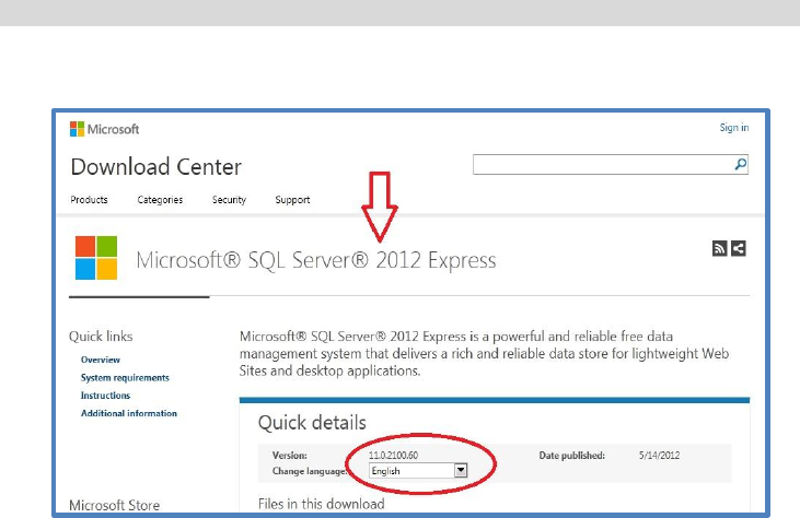
5.2 Installation of Database Server (cont.)
Select Language, download “SQLEXPRWT_x86” (for 32bit/64 bit systems) to install
SQL Server 2012 Express.

14
5.2 Installation of Database Server (cont.)
Select “New Installation”

15
5.2 Installation of Database Server (cont.)
Accept the License Terms, then click “Next”

16
5.2 Installation of Database Server (cont.)
Installation will check for product updates when internet service is connected.
Click “Next” to continue…
17
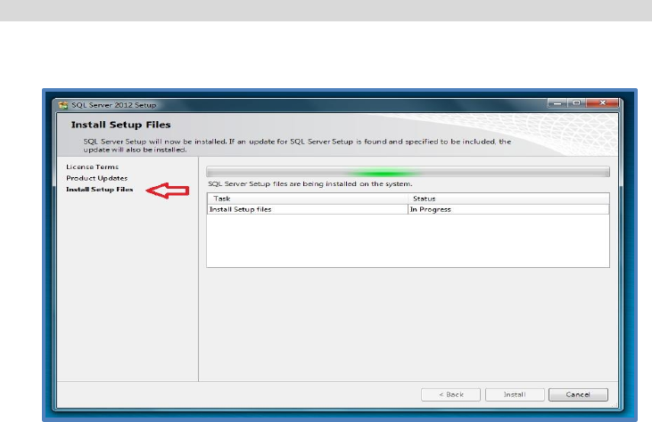
5.2 Installation of Database Server (cont.)
Installation in progress…

18
5.2 Installation of Database Server (cont.)
Click “Next” to continue…

19
5.2 Installation of Database Server (cont.)
Click “Next” to continue…
20
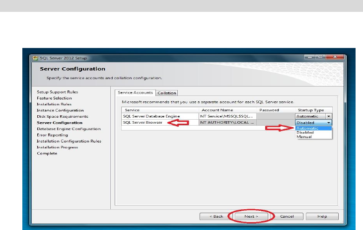
5.2 Installation of Database Server (cont.)
Set “SQL Server Browser” to Automatic and click “Next” to continue…

21
5.2 Installation of Database Server (cont.)
Set “Authentication Mode” to “Mixed Mode”, then enter and confirm password.
E.g. Password = GIRSAdmin, but can choose another password.
Click “Next” to continue…

22
5.2 Installation of Database Server (cont.)
Click “Next” to continue…

23
5.2 Installation of Database Server (cont.)
Installation in progress…

24
5.2 Installation of Database Server (cont.)
Installation of SQL Server is completed.
“Close” SQL Server 2012 Setup.

25
5.3 SQL Server Setting
Place the GIRS program disc in the CD-Rom tray. Open file folder to view.
Copy the folder D:\database to C:\Temp\

26
5.3 SQL Server Setting (cont.)
Double click to run “restoreDB” at C:\Temp\database

27
5.3 SQL Server Setting (cont.)
Press ‘Y’ to continue…

28
5.3 SQL Server Setting (cont.)
Press any key to continue…
Now the database of SQL Server is restored.

29
5.3 SQL Server Setting (cont.)
Use administrator mode to run D:\utility\OpenSqlServerPort in GIRS program disc
(open SQL server port)
30
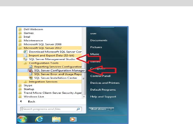
5.3 SQL Server Setting (cont.)
Open SQL Server Configuration Manager
31
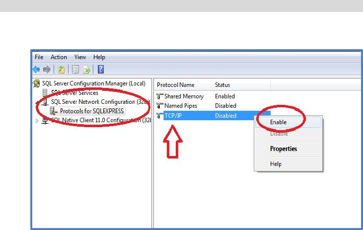
5.3 SQL Server Setting (cont.)
Enable TCP/IP from SQL Server Configuration Manager

32
5.3 SQL Server Setting (cont.)
Open Properties of TCP/IP

33
5.3 SQL Server Setting (cont.)
Under Protocol, “Listen All” is set to ‘Yes’;
For “IPAll” under ‘IP Addresses’, delete any data in TCP Dynamic Ports
and set TCP Port to 1433.
34
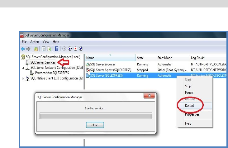
5.3 SQL Server Setting (cont.)
Restart the SQL Server…

35
5.3 SQL Server Setting (cont.)
Exit the SQL Server Configuration Manager
Now continue with the installation of GIRS program…

36
5.4 Installation of GIRS
Place GIRS Program Disc into CD-Rom drive of your computer
The autoplay dialogue box will pop up; (The GIRS version no. may not be the same
since the most update version will be included)
Select “setup.exe”

37
5.4 Installation of GIRS (cont.)
Click “Next” to continue…

38
5.4 Installation of GIRS (cont.)
Select “Everyone”, then click “Next” to complete GIRS installation
“Close” to complete installation of GIRS.

39
5.4 Installation of GIRS (cont.)
The following icons will be setup at computer’s desktop:
GIRS Supervisor GIRS Inspector

40
6. How to Use GIRS
There are two main parts of the GIRS program : the “Supervisor” and the
“Inspector”, for different groups of user.
The Supervisor program is to be used by the System Administrator, management
and supervisor.
The Inspector program is to be used by the internal Inspectors or customer
representatives.
The program defines three groups of users :
1. Admin (system administrator, management)
2. Supervisor
3. Not a Supervisor
For ”Not a Supervisor”, there are sub-groups of :
1. Not an inspector
2. In-line inspector
3. Final inspector
4. Customer
41
6. How to Use GIRS (cont.)
The rights of different groups of user are listed in the table below:
User’s Right
Admin
Supervisor
Not a Supervisor
Login to GIRS
Supervisor
Yes
Yes
No
Add, Edit, Delete
User
Yes
No
No
Add, Edit, Delete
Specification
Yes
Yes
No
Edit, Delete
Inspection Results
Yes
Yes
No
View, Print
Inspection Results
Yes
Yes
Yes

42
6.1 GIRS Supervisor
Login GIRS Supervisor
For the first time, use the preset Administrator to login :
Username : Admin
Password : Admin
Administrator can change the password after first time login
Click the Supervisor icon to
start GIRS Supervisor
43
6.1 GIRS Supervisor (cont.)
There are three major functions of GIRS Supervisor :
User Setup
Specification (add, edit, delete)
Inspection Result (view, edit, delete, print)
By selecting the User Setup, the Administrator can add, edit or delete users.

44
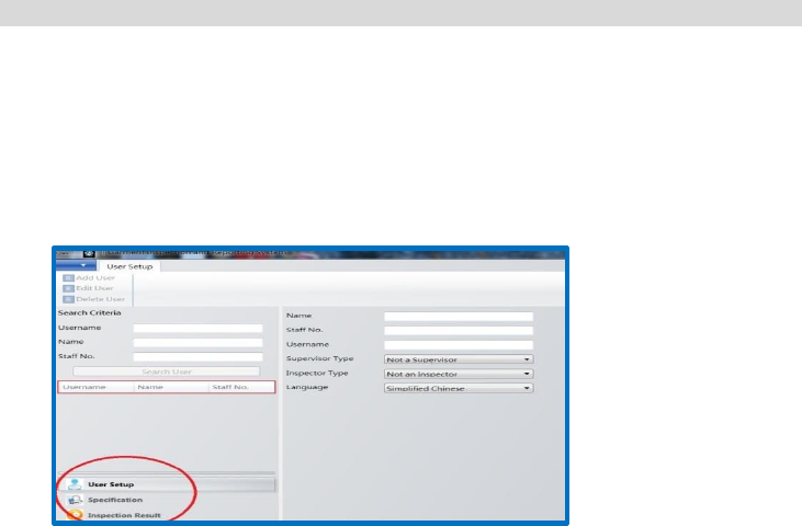
6.1.1 User Setup
Add User (Only the Administrator has the right to add, edit or delete user)
Select “Add User” under “User Setup”
Input details of new user
Create Password for new user
User password can be changed anytime by administrator as required

45
6.1.1 User Setup (cont.)
Select “User Type”, “Language” and then save
46
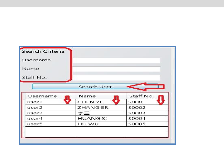
6.1.1 User Setup (cont.)
Search registered users:
Input search criteria, or
Click “Search User” to view, list can be sort to order under different tabs

47
6.1.1 User Setup (cont.)
Edit User
Select “Edit User” under “User Setup”
Edit user details and password
Click “Save” and confirm update

48
6.1.1 User Setup (cont.)
Delete User
Pick the user you want to delete
Select “Delete User” under “User Setup”
Make sure before you confirm the “Delete” action

49
6.1.2 Specification
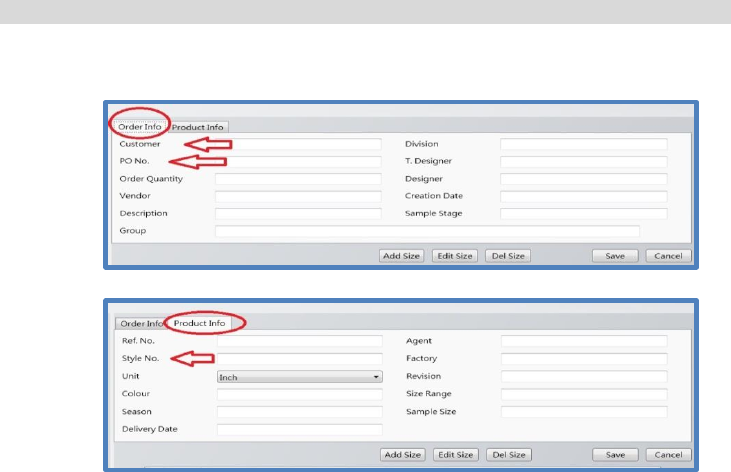
Add Specification
Select “Add Spec” under “Specification”
Input “Order Info” and “Product Info”
50
6.1.2 Specification (cont.)
Customer, PO No. and Style No. are compulsory entries for all specifications
51
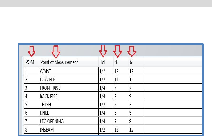
6.1.2 Specification (cont.)
Add “Size”, “POM”(Abbrev. for Point of Measurement), “Point of
Measurement” and “Tol”(Tolerance)
“Save” and confirm adding a new specification

52
6.1.2 Specification (cont.)
Edit Specification
Input Search criteria to look for registered specification, or
Click “Search Specification” to view, list can be sort to order under different
tabs
“Save” to confirm update

53
6.1.2 Specification (cont.)
Copy Specification : to reproduce a similar specification
Input Search criteria to look for registered specification, or
Select “Search Specification” to view, list can be sort to order under different
tabs
Click “Copy Spec” under “Specification”
Input new details for “Order Info” and “Product Info” to replace the old
details
Save to add a new specification

54
6.1.2 Specification (cont.)
Delete Specification
Select the spec to be deleted
Click “Delete Spec” under “Specification”
Double check before you confirm to delete specification
Specifications already performed inspection measurement cannot be
deleted
55
6.1.2 Specification (cont.)
Print Specification
Select the spec to be printed
Click “Print Spec” under “Specification”
56
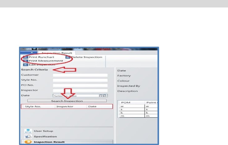
6.1.3 Inspection Result
Print Inspection Result
Search and select the inspection result
Click Print “Runchart” or “Measurement“
57
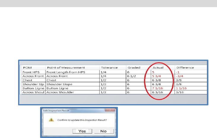
6.1.3 Inspection Result
Edit Inspection
Search and select inspection result
Click “Edit Inspection” under Inspection Result”
Only the actual measurement data can be edited
Save and confirm to update the inspection result
58
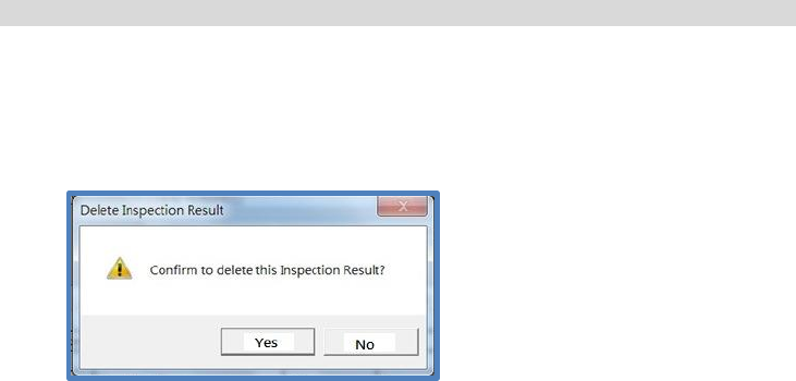
6.1.3 Inspection Result (cont.)
Delete Inspection
Search and select inspection result
Click “Delete Inspection” under “Inspection Result”
Make sure before your confirm to “delete” the inspection result

59
6.2 GIRS Inspector
Login GIRS Inspector
Use the Username and Password as assigned by Administrator to login GIRS
Inspector.
Click the Inspector icon to start
GIRS Inspector
60
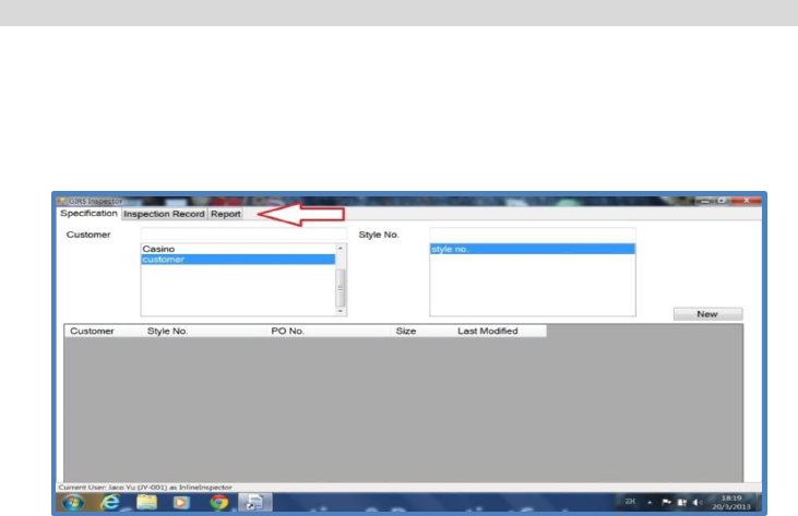
6.2 GIRS Inspector (cont.)
There are three major functions of GIRS Inspector :
Specification : to select specification and start new inspection
Inspection Record : to search and view inspection record
Report : to search and print inspection report

61
6.2.1 Specification
Start New Inspection :
Plug in the USB receiver into any USB port of your computer. The LED on the
receiver will light on
Power on the measuring tape by pressing any one of the key switches
Select Specification and start New Inspection
When a POM is measured, by pressing the “TRANSFER” key switch, the
reading on the display unit will be transferred to your computer via the USB
receiver. You should hear either a “DING” or a warning sound from your
computer to confirm the data has been transferred and received.
62
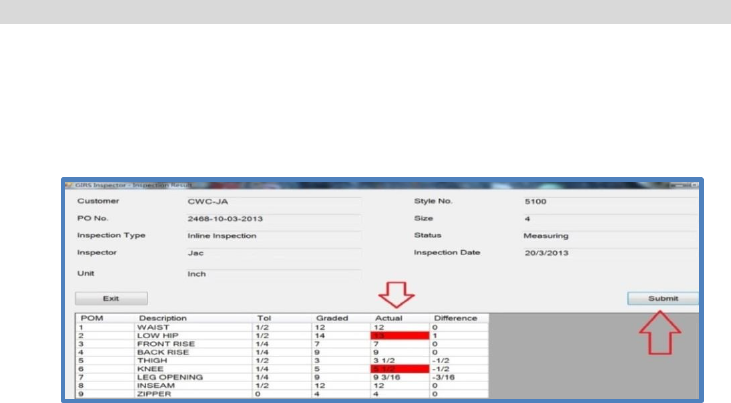
6.2.1 Specification (cont.)
Strictly follow the order of POM in taking measurement
The measurement data and difference to TOL will be recorded
Data out of tolerance will be shown in red with “warning sound”
“Submit” after each inspection; click “Start” to take new inspection
“Exit” when all inspections of each batch completed
Remark : In case the working environment is too noisy to hear the “DING” or warning
sound, user can consider to connect external powered speakers to the computer.
63
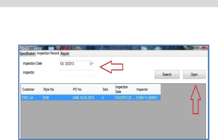
6.2.2 Inspection Record
Search Inspection Records
Inspection records can be searched by date of inspection
Open to view records
64
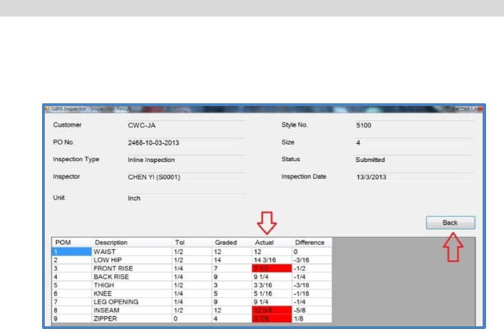
6.2.2 Inspection Record (cont.)
View Inspection Records
Data out of tolerance is shown in red
“Back” to close the current inspection record, search to view other records
65
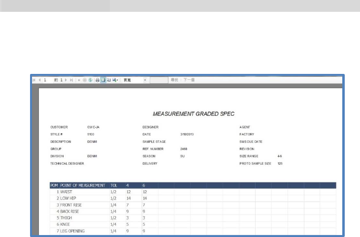
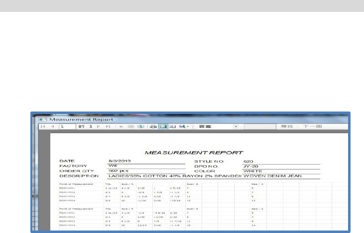
6.2.3 Report
Search or Print Measurement Reports / Runchart Reports
Reports can be searched by date of inspection
View or Print Measurements / Runchart Reports
Logout GIRS Inspector when finish
Sample of Measurement Report
66
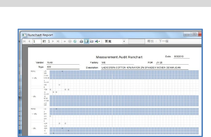
6.2.3 Report
Sample of Runchart Report

67
7. Network Application
GIRS is designed to run on both stand-alone and multi-user networked
environment.
In case of a networked environment, two or more computers can be linked up by
LAN (Local Area Network) through a HUB or a wireless router. All GIRS data will be
saved in the hard disk of the host Server computer, and can be accessed and
viewed from any one of the computers.
Only one computer (the host Server) need to install the SQL Server and the GIRS
program. The other computers (Inspection stations) need only to install the GIRS
program; and the data in the host Server can be shared among computers in the
same network.
Please consult your IT staff or external IT experts to support in setting up the
network.

68
7. Network Application (cont.)
A typical example of network setup is shown below.

69
7.1 Client Station Setting
Login the computer used at the Inspection Station (Client)
Double click the GIRS “Supervisor” icon to start program and you will see the
screen below.

70
7.1 Client Station Setting (cont.)
Input name of remote SQL Server
Select SQL Server Authentication :
Input :
User ID = GIRSAdmin
Password = GIRSAdmin
Reconfirm Password = GIRSAdmin
Save the settings
Client Station setting is completed and the communication with the Host Server is
activated.

71
8. Data Maintenance
All GIRS data (users, specifications, measurement reports) are stored in the hard disk
drive of your computer (stand-alone) or the server (networked). In order to protect
your data, we strongly advise you to back up your data by an external hard disk drive
at a regular period.
Please consult your IT staff or external IT experts on how to back up your data.

72
9. Trouble Shooting and Services
Cannot power on your measuring tape
Check if the batteries are placed into the battery compartment correctly.
Make sure the batteries are at correct polarity and with good contact to the
metal terminals.
Replace the batteries with new ones.
Reading on display unit is not correct
Check if there is any residual value on the display unit when tape is fully
retracted. If not, set the residual reading to “0.0” by pressing the ZERO key
switch.
Data cannot be transferred to your computer
Check if the USB receiver is correctly plugged onto your computer.
Check if the LED on the USB receiver lights on. If not, you may need to
replace your USB receiver.
Check if you have used another USB receiver of another measuring tape.
Check the serial number on the labels of the USB receiver and inside the
battery compartment of the measuring tape. The two serial numbers should

73
9. Trouble Shooting and Services (cont.)
be the same. If not, you must have mixed up the USB receiver and you have
to find the correct USB receiver.
Return the measuring tape to your agent or distributor if the above steps cannot
solve your problem.
Do not attempt to open up the measuring tape and repair by yourself. This will
void the warranty as provided by the manufacturer.

74
10. Warranty
One Year Warranty
E Measuring Device Limited or its authorized agent or distributor warrant all products
against defects in materials and workmanship for a period of one (1) Year from the
date of original consumer purchase. If a defect exists during the warranty period,
EMD or its option will either repair or replace the product at no charge.
The warranty will not apply to the product if it has been damaged by misuse,
alternation, accident, improper handling or operation, or if unauthorized repairs are
attempted or made. Some example of damages not covered by warranty include, but
not limited to, battery leakage, bending of steel tape, visible cracking of the LCD
display or plastic casing, which are presumed to be damages resulting from misuse or
abuse.

75
11. Product Specification
Specification is subject to change without prior notice. The illustrated product may differ
form that supplied.
System Model No. GS-188
Device Model No. DT-138 (measuring tape)
Tape Length 1.6 M
Tape Width 13 mm
Tape Print In both British and Metric standand
LCD Display In INCH, fractions, 1/16 resolution
In CM, 1 decimal
Dimension 110 x 55 x 25 mm (LxHxD)
Weight 105 gm excluding battery
Power Source 3V, DC, 2 x AAA Battery
Battery Life 80-100 working hours
Data Output Interface Wireless RF output through an USB receiver
Protocol: SDTP (Short Distance Digital Transceiving Protocol)
RF: SFP (Static Frequency Pair)
Range: 2.4-2.4835 GHz
Control Buttons IN-CM Unit conversion (inch/cm)
ZERO Set zero
TRANSFER Data transfer
Power Management Power on by any button
Auto power off after 60 seconds idle
Battery low warning
76
77
78

79
E Measuring Device Limited
3/F, Fook Cheong Building,
63 Hoi Yuen Road, Kwun Tong,
Kowloon, Hong Kong
Tel : (852) 2152 6063
Fax : (852) 2151 1155
Email : enquiry@emeasuring.com.hk
裕明電子有限公司
地址 : 香港九龍官塘開源道 63 號
福昌大廈 3樓
電話 : (852) 2152 6063
傳真 : (852) 2151 1155
電郵 : enquiry@emeasuring.com.hk
© 2013 E Measuring Device Limited
All rights reserved
©2013 裕明電子有限公司
保留所有权利